
WEB-ADMIN CONFIGURATION - Altai · Altai Technologies Ltd. All rights reserved C1n Web-admin...
77
Altai Technologies Ltd. All rights reserved ALTAI C1N SUPER WIFI AP/CPE WEB-ADMIN CONFIGURATION MANUAL Version 1.0 Date: September, 2013
Transcript of WEB-ADMIN CONFIGURATION - Altai · Altai Technologies Ltd. All rights reserved C1n Web-admin...
Altai Technologies Ltd. All rights reserved
ALTAI C1N SUPER WIFI AP/CPE
WEB-ADMIN
CONFIGURATION
MANUAL
Version 1.0
Date: September, 2013
Altai Technologies Ltd. All rights reserved
C1n Web-admin Configuration Manual
TPS13-001_rev1.0
Copyright © 2007Altai Technologies Limited
ALL RIGHTS RESERVED.
Altai Technologies Limited
Unit 209, 2/Floor,
East Wing, Building 17
Hong Kong Science Park,
Sha Tin, New Territories,
Hong Kong
Telephone: +852 3758 6000
Fax: +852 2607 4021
Web: www.altaitechnologies.com
Customer Support Centre:
Email: [email protected]
Radio Frequency Interference Requirements
This device complies with Part 15 of FCC Rules.
Operation is subject to the following conditions:
1. This device may not cause harmful interference.
2. This device must accept any interference received, including interference
that may cause undesired operation.
3. This device should not be co-located or operating in conjunction with any
other antenna or transmitter.
Interference Statement
This equipment has been tested and found to comply with the limits for a Class B
digital device, pursuant to Part 15 of the FCC Rules. These limits are designed to
provide reasonable protection against harmful interference in a residential installation.
This equipment generates uses and can radiate radio frequency energy. If it is not
installed and used in accordance with the instructions, harmful interference to radio
communications may be caused.
However, there is no guarantee that interference will not occur in a particular
installation. If this equipment does cause harmful interference to radio or television
reception, which can be determined by turning the equipment off and on, the user is
encouraged to try to correct the interference by one of the following measures:
Altai Technologies Ltd. All rights reserved
C1n Web-admin Configuration Manual
TPS13-001_rev1.0
- Reorient or relocate the receiving antenna.
- Increase the separation between the equipment and receiver.
- Connect the equipment into an outlet on a circuit different from that
to which the receiver is connected.
- Consult the dealer or an experienced radio/TV technician for help.
FCC Caution: To assure continued compliance, (example – use only shielded
interface cables when connecting to computer or peripheral devices) any changes
or modifications not expressly approved by the party responsible for compliance
could void the user’s authority to operate this equipment.
Warning
The user is advised to keep away from the base-station and antenna with at least
45cm when the base-station is in operation.
Please install a lightning arrestor to protect the base station from lightning dissipation
during rainstorms. Lightning arrestors are mounted outside the structure and must be
grounded by means of a ground wire to the nearest ground rod or item that is
grounded.
Disclaimer
All specifications are subject to changes without prior notice. Altai Technologies
assumes no responsibilities for any inaccuracies in this document or for any obligation
to update information in this document. This document is provided for information
purposes only. Altai Technologies reserves the right to change, modify, transfer, or
otherwise revise this publication without notice.
Altai Technologies Ltd. All rights reserved
C1n Web-admin Configuration Manual
TPS13-001_rev1.0
Contents
1. Introduction ..................................................................................................................................... 7
2. C1n Model and Firmware Version .................................................................................................... 7
3. Getting Started ................................................................................................................................ 7
3.1. Setup Local Area Connection on Your PC ................................................................................... 7 3.2. Check Access .............................................................................................................................. 10 3.3. Configuration with Web-Admin ................................................................................................ 10 3.4. Interface Introduction ............................................................................................................... 12 3.5. Logout from C1n Interface ........................................................................................................ 13
4. System Status ................................................................................................................................ 13
4.1. Interface ..................................................................................................................................... 14 4.1.1. 2.4G Interface Status ............................................................................................................ 15
4.1.1.1. Status .......................................................................................................................................... 15 4.1.1.2. Statistic ....................................................................................................................................... 16 4.1.1.3. Channel Usage ........................................................................................................................... 16 4.1.1.4. WLAN .......................................................................................................................................... 18 4.1.1.5. Association List .......................................................................................................................... 19
4.1.2. Ethernet Interface ................................................................................................................ 20 4.1.2.1. Status .......................................................................................................................................... 20 4.1.2.2. Statistic ....................................................................................................................................... 21
4.1.3. Logs ........................................................................................................................................ 21 4.1.3.1. System Log ................................................................................................................................. 21 4.1.3.2. Panic Log .................................................................................................................................... 23 4.1.3.3. Alarm Log ................................................................................................................................... 23
5. System Configuration ..................................................................................................................... 24
5.1. C1n Configuration Procedures .................................................................................................. 24 5.2. Basic Configuration .................................................................................................................... 26
5.2.1. Basic System Configuration .................................................................................................. 26 5.2.2. Network Configuration ......................................................................................................... 27
5.2.2.1. General Network Configuration ................................................................................................ 27 5.2.2.1.1. Network Setting—Switch Mode ......................................................................................... 29 5.2.2.1.2. Network Setting—Gateway Mode ...................................................................................... 30 5.2.2.1.3. WAN Setting (IPv4) ............................................................................................................... 31 5.2.2.1.4. Static IP (IPv4) ....................................................................................................................... 31 5.2.2.1.5. DHCP (IPv4)........................................................................................................................... 32 5.2.2.1.6. Ethernet Mode ..................................................................................................................... 34
5.2.2.2. VLAN ........................................................................................................................................... 36 5.2.2.3. DHCP Server ............................................................................................................................... 36 5.2.2.4. Port Forwarding ......................................................................................................................... 38 5.2.2.5. Safe Mode .................................................................................................................................. 40
6. Wireless ......................................................................................................................................... 41
6.1. 2.4G Radio .................................................................................................................................. 41 6.1.1. 2.4G General Configuration ................................................................................................. 42
6.1.1.1. 2.4G WLAN ................................................................................................................................. 43 6.1.1.1.1. WLAN X (0-7) WLAN Setting ................................................................................................ 44 6.1.1.1.2. WLAN X (0-7) Security .......................................................................................................... 45 6.1.1.1.3. WLAN X (0-7) Rogue Station List ......................................................................................... 53 6.1.1.1.4. WLAN X (0-7) QoS ................................................................................................................ 54 6.1.1.1.5. WLAN X (0-7) Bandwidth Control ........................................................................................ 55
6.1.1.2. 2.4G Advanced Configuration ................................................................................................... 55 6.1.1.3. 2.4G Wireless QoS Configuration ............................................................................................. 59 6.1.1.4. 2.4G WEP Key ............................................................................................................................ 60
6.2. Thin AP Configuration ................................................................................................................ 60
Altai Technologies Ltd. All rights reserved
C1n Web-admin Configuration Manual
TPS13-001_rev1.0
7. Administration Configuration ......................................................................................................... 61
7.1. Administration General Setting ................................................................................................ 61 7.2. Web Admin ................................................................................................................................ 62 7.3. SNMP Setting ............................................................................................................................. 63 7.4. Certificate Management ........................................................................................................... 64 7.5. Firmware Update ....................................................................................................................... 65 7.6. Reset Back to Factory Default via User Interface..................................................................... 68 7.7. Backup/Restore.......................................................................................................................... 68
8. Tools .............................................................................................................................................. 70
8.1. Channel Scan .............................................................................................................................. 70 8.2. Diagnosis .................................................................................................................................... 73
8.2.1. Ping to Host ........................................................................................................................... 74 8.2.2. Traceroute to Host ............................................................................................................... 74
8.3. Watchdog ................................................................................................................................... 75
9. C1n Information ............................................................................................................................. 76
Altai Technologies Ltd. All rights reserved
C1n Web-admin Configuration Manual
TPS13-001_rev1.0
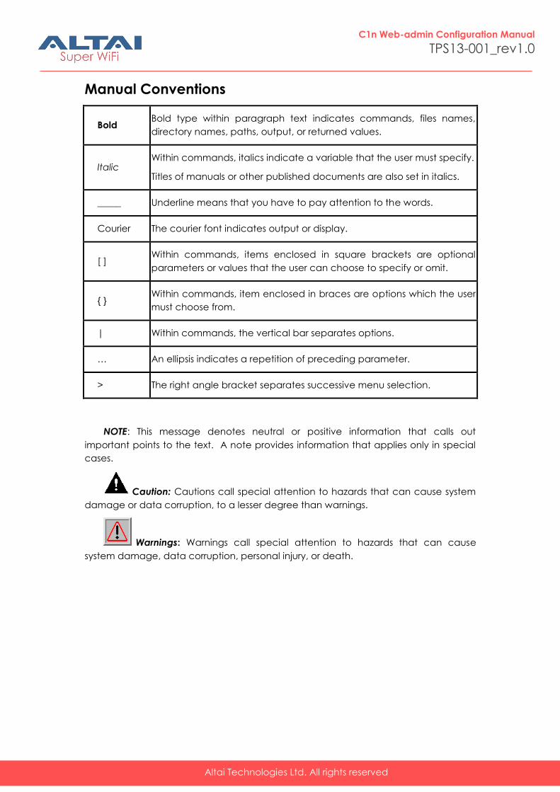
Manual Conventions
Bold Bold type within paragraph text indicates commands, files names,
directory names, paths, output, or returned values.
Italic Within commands, italics indicate a variable that the user must specify.
Titles of manuals or other published documents are also set in italics.
_____ Underline means that you have to pay attention to the words.
Courier The courier font indicates output or display.
[ ] Within commands, items enclosed in square brackets are optional
parameters or values that the user can choose to specify or omit.
{ } Within commands, item enclosed in braces are options which the user
must choose from.
| Within commands, the vertical bar separates options.
… An ellipsis indicates a repetition of preceding parameter.
> The right angle bracket separates successive menu selection.
NOTE: This message denotes neutral or positive information that calls out
important points to the text. A note provides information that applies only in special
cases.
Caution: Cautions call special attention to hazards that can cause system
damage or data corruption, to a lesser degree than warnings.
Warnings: Warnings call special attention to hazards that can cause
system damage, data corruption, personal injury, or death.
Altai Technologies Ltd. All rights reserved
C1n Web-admin Configuration Manual
TPS13-001_rev1.0
1. Introduction
This manual is to summarize how to perform basic configuration for the Altai C1n
AP/CPE through web-admin interface.
2. C1n Model and Firmware Version
This manual is applicable for the following models, hardware and firmware versions:
Product name : C1n AP/CPE
Hardware
Platform Firmware Version
V1.0 1.2.4.x
Table 2-1 C1n Model
3. Getting Started
3.1. Setup Local Area Connection on Your PC
C1n AP/CPE can be connected to your PC in wired mode or in wireless mode. In the
following, wired mode will be introduced. This is because the configurations are
similar in wireless mode, except SSID has to be configured in both C1n AP/CPE and
PC.
C1n AP/CPE can be connected to your PC directly or by a switch or a hub.
Start Network Configuration on your PC.
For Windows XP user,
1. Click the “Start” menu and choose “Control Panel”.
2. Click “Network Connections”.
Altai Technologies Ltd. All rights reserved
C1n Web-admin Configuration Manual
TPS13-001_rev1.0
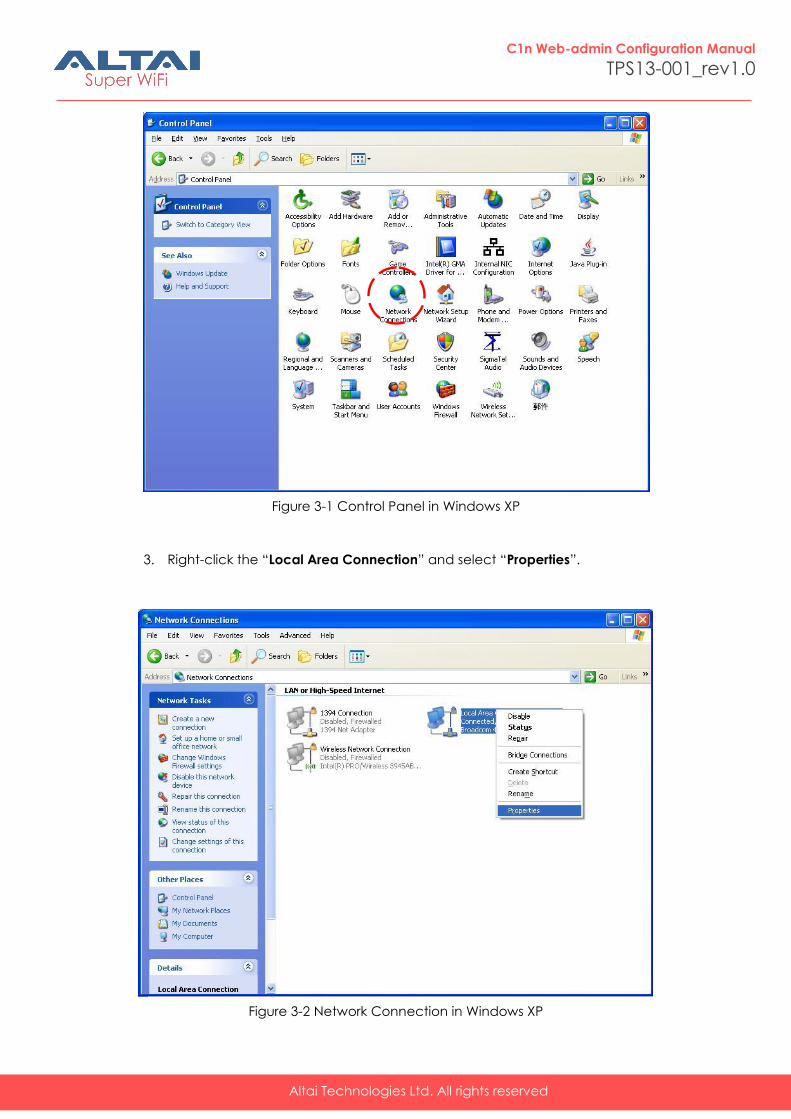
Figure 3-1 Control Panel in Windows XP
3. Right-click the “Local Area Connection” and select “Properties”.
Figure 3-2 Network Connection in Windows XP
Altai Technologies Ltd. All rights reserved
C1n Web-admin Configuration Manual
TPS13-001_rev1.0
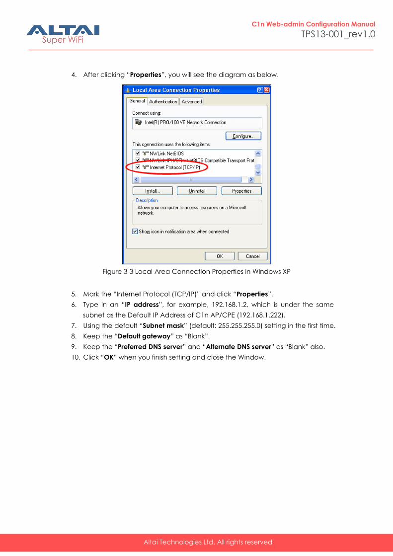
4. After clicking “Properties”, you will see the diagram as below.
Figure 3-3 Local Area Connection Properties in Windows XP
5. Mark the “Internet Protocol (TCP/IP)” and click “Properties”.
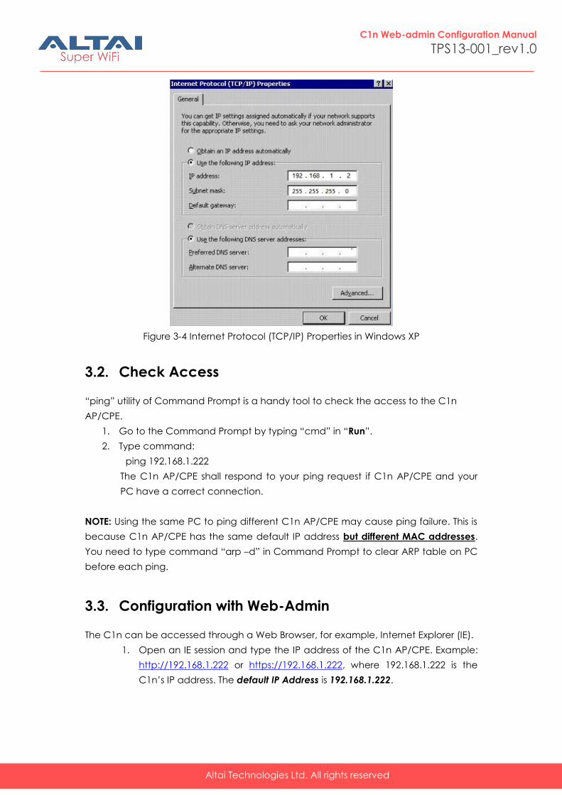
6. Type in an “IP address”, for example, 192.168.1.2, which is under the same
subnet as the Default IP Address of C1n AP/CPE (192.168.1.222).
7. Using the default “Subnet mask” (default: 255.255.255.0) setting in the first time.
8. Keep the “Default gateway” as “Blank”.
9. Keep the “Preferred DNS server” and “Alternate DNS server” as “Blank” also.
10. Click “OK” when you finish setting and close the Window.
Altai Technologies Ltd. All rights reserved
C1n Web-admin Configuration Manual
TPS13-001_rev1.0
Figure 3-4 Internet Protocol (TCP/IP) Properties in Windows XP
3.2. Check Access
“ping” utility of Command Prompt is a handy tool to check the access to the C1n
AP/CPE.
1. Go to the Command Prompt by typing “cmd” in “Run”.
2. Type command:
ping 192.168.1.222
The C1n AP/CPE shall respond to your ping request if C1n AP/CPE and your
PC have a correct connection.
NOTE: Using the same PC to ping different C1n AP/CPE may cause ping failure. This is
because C1n AP/CPE has the same default IP address but different MAC addresses.
You need to type command “arp –d” in Command Prompt to clear ARP table on PC
before each ping.
3.3. Configuration with Web-Admin
The C1n can be accessed through a Web Browser, for example, Internet Explorer (IE).
1. Open an IE session and type the IP address of the C1n AP/CPE. Example:
http://192.168.1.222 or https://192.168.1.222, where 192.168.1.222 is the
C1n’s IP address. The default IP Address is 192.168.1.222.
Altai Technologies Ltd. All rights reserved
C1n Web-admin Configuration Manual
TPS13-001_rev1.0
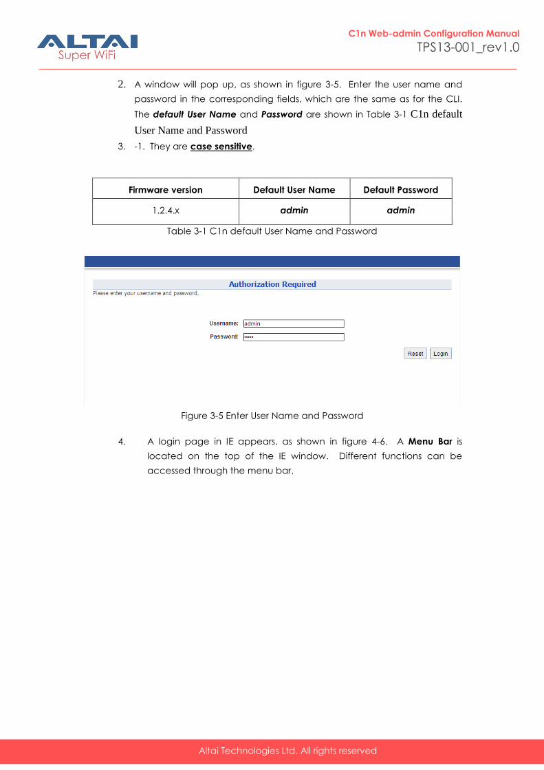
2. A window will pop up, as shown in figure 3-5. Enter the user name and
password in the corresponding fields, which are the same as for the CLI.
The default User Name and Password are shown in Table 3-1 C1n default
User Name and Password
3. -1. They are case sensitive.
Firmware version Default User Name Default Password
1.2.4.x admin admin
Table 3-1 C1n default User Name and Password
Figure 3-5 Enter User Name and Password
4. A login page in IE appears, as shown in figure 4-6. A Menu Bar is
located on the top of the IE window. Different functions can be
accessed through the menu bar.
Altai Technologies Ltd. All rights reserved
C1n Web-admin Configuration Manual
TPS13-001_rev1.0
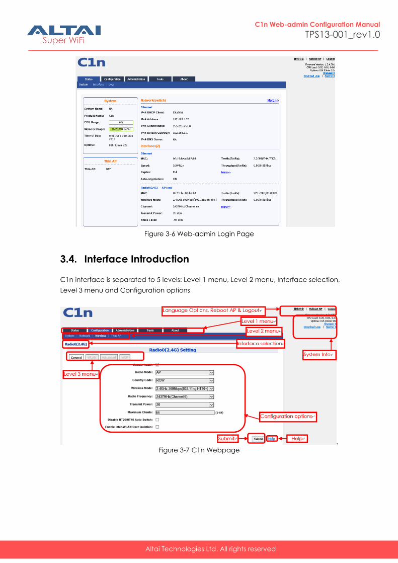
Figure 3-6 Web-admin Login Page
3.4. Interface Introduction
C1n interface is separated to 5 levels: Level 1 menu, Level 2 menu, Interface selection,
Level 3 menu and Configuration options
Figure 3-7 C1n Webpage
Altai Technologies Ltd. All rights reserved
C1n Web-admin Configuration Manual
TPS13-001_rev1.0
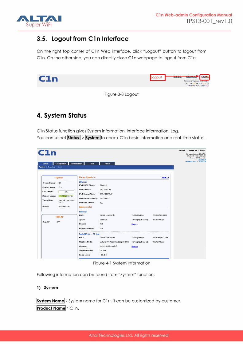
3.5. Logout from C1n Interface
On the right top corner of C1n Web interface, click “Logout” button to logout from
C1n. On the other side, you can directly close C1n webpage to logout from C1n.
Figure 3-8 Logout
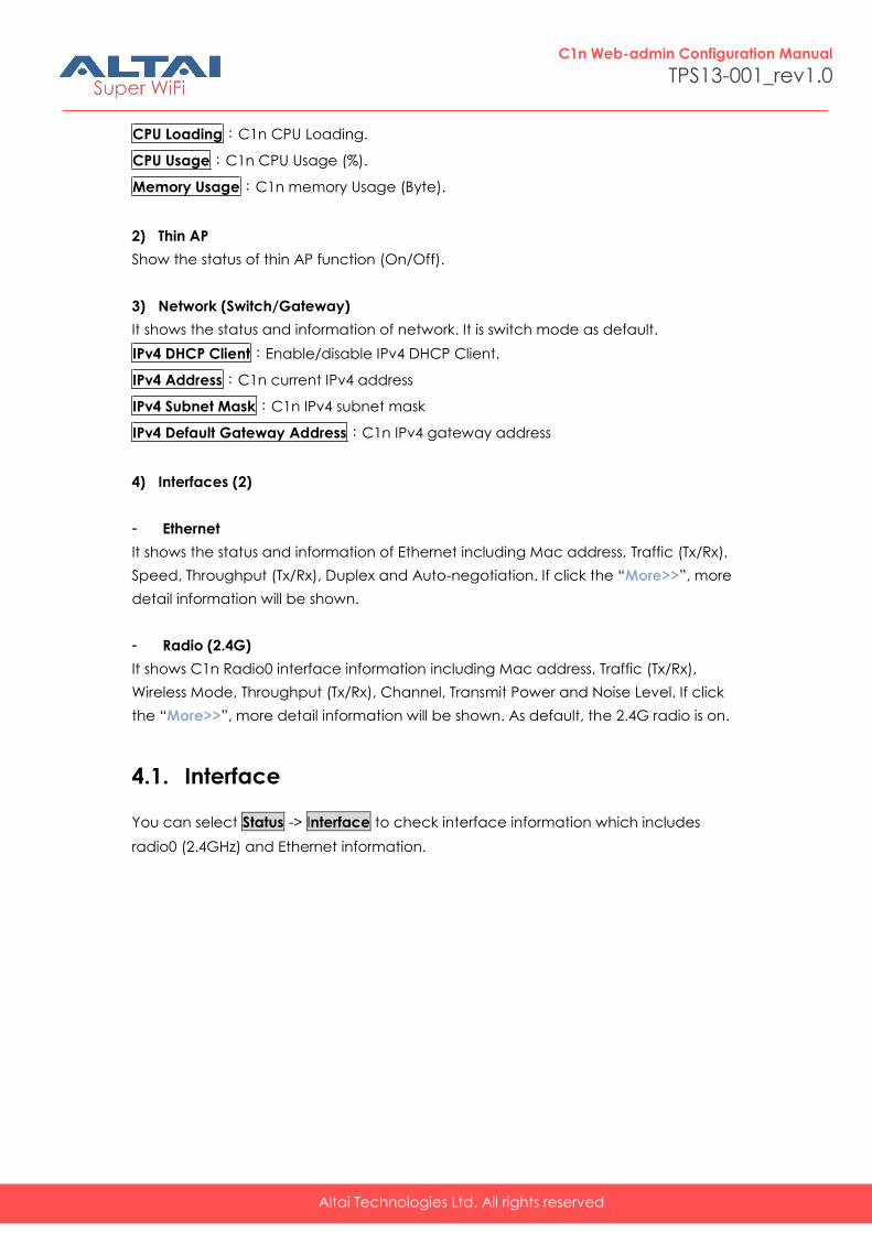
4. System Status
C1n Status function gives System information, interface information, Log.
You can select Status -> System to check C1n basic information and real-time status.
Figure 4-1 System Information
Following information can be found from “System” function:
1) System
System Name:System name for C1n, it can be customized by customer.
Product Name:C1n.
Logout
Altai Technologies Ltd. All rights reserved
C1n Web-admin Configuration Manual
TPS13-001_rev1.0
CPU Loading:C1n CPU Loading.
CPU Usage:C1n CPU Usage (%).
Memory Usage:C1n memory Usage (Byte).
2) Thin AP
Show the status of thin AP function (On/Off).
3) Network (Switch/Gateway)
It shows the status and information of network. It is switch mode as default.
IPv4 DHCP Client:Enable/disable IPv4 DHCP Client.
IPv4 Address:C1n current IPv4 address
IPv4 Subnet Mask:C1n IPv4 subnet mask
IPv4 Default Gateway Address:C1n IPv4 gateway address
4) Interfaces (2)
- Ethernet
It shows the status and information of Ethernet including Mac address, Traffic (Tx/Rx),
Speed, Throughput (Tx/Rx), Duplex and Auto-negotiation. If click the “More>>”, more
detail information will be shown.
- Radio (2.4G)
It shows C1n Radio0 interface information including Mac address, Traffic (Tx/Rx),
Wireless Mode, Throughput (Tx/Rx), Channel, Transmit Power and Noise Level. If click
the “More>>”, more detail information will be shown. As default, the 2.4G radio is on.
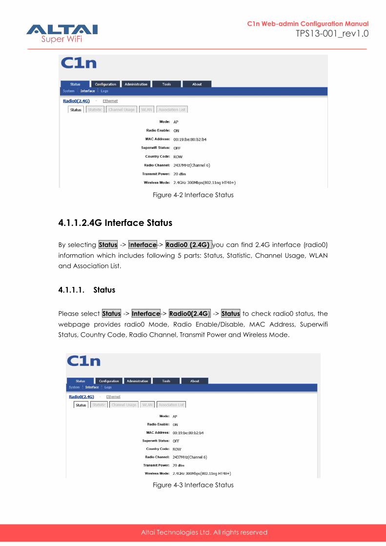
4.1. Interface
You can select Status -> Interface to check interface information which includes
radio0 (2.4GHz) and Ethernet information.
Altai Technologies Ltd. All rights reserved
C1n Web-admin Configuration Manual
TPS13-001_rev1.0
Figure 4-2 Interface Status
4.1.1. 2.4G Interface Status
By selecting Status -> Interface-> Radio0 (2.4G) you can find 2.4G interface (radio0)
information which includes following 5 parts: Status, Statistic, Channel Usage, WLAN
and Association List.
4.1.1.1. Status
Please select Status -> Interface-> Radio0(2.4G) -> Status to check radio0 status, the
webpage provides radio0 Mode, Radio Enable/Disable, MAC Address, Superwifi
Status, Country Code, Radio Channel, Transmit Power and Wireless Mode.
Figure 4-3 Interface Status
Altai Technologies Ltd. All rights reserved
C1n Web-admin Configuration Manual
TPS13-001_rev1.0
Mode: Operation mode
Radio Enable:Radio0 (2.4G) status (ON/OFF)
MAC Address:Radio0 (2.4G) MAC address.
Superwifi Status:Superwifi Status (ON/OFF), as default, it is on.
Country Code:Country Code.
Radio Channel:Radio0 (2.4G) current channel
Transmit Power:Radio0 (2.4G) transmit power
Wireless Mode:Radio0 (2.4G) wireless mode
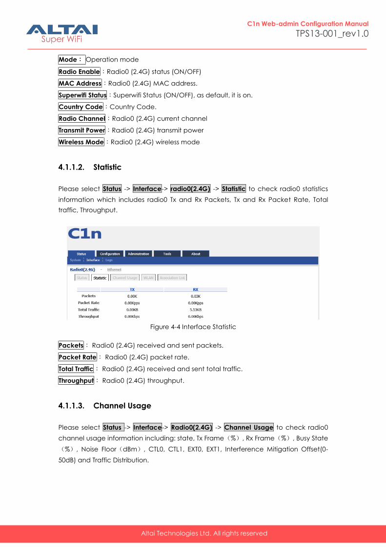
4.1.1.2. Statistic
Please select Status -> Interface-> radio0(2.4G) -> Statistic to check radio0 statistics
information which includes radio0 Tx and Rx Packets, Tx and Rx Packet Rate, Total
traffic, Throughput.
Figure 4-4 Interface Statistic
Packets: Radio0 (2.4G) received and sent packets.
Packet Rate: Radio0 (2.4G) packet rate.
Total Traffic: Radio0 (2.4G) received and sent total traffic.
Throughput: Radio0 (2.4G) throughput.
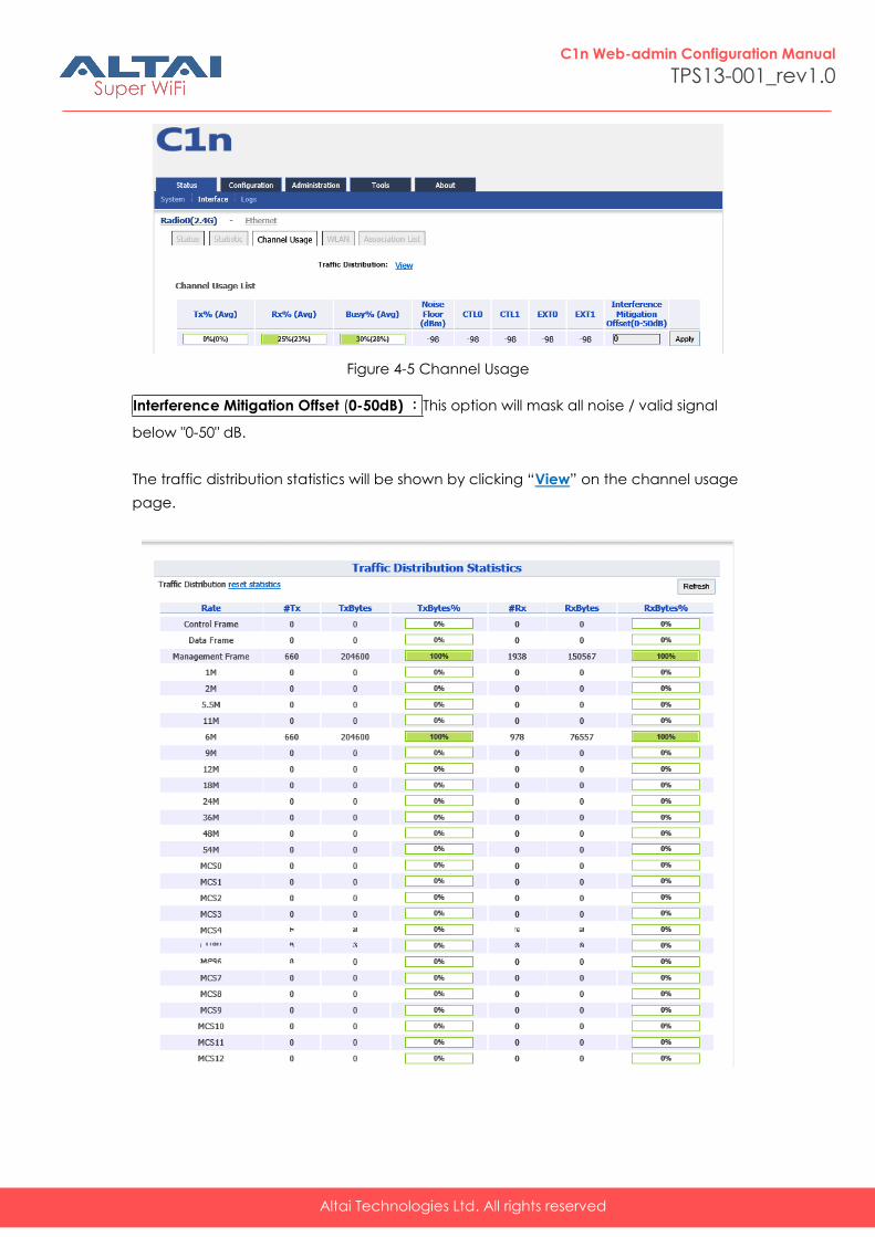
4.1.1.3. Channel Usage
Please select Status -> Interface-> Radio0(2.4G) -> Channel Usage to check radio0
channel usage information including: state, Tx Frame(%), Rx Frame(%), Busy State
(%), Noise Floor(dBm), CTL0, CTL1, EXT0, EXT1, Interference Mitigation Offset(0-
50dB) and Traffic Distribution.
Altai Technologies Ltd. All rights reserved
C1n Web-admin Configuration Manual
TPS13-001_rev1.0
Figure 4-5 Channel Usage
Interference Mitigation Offset (0-50dB) :This option will mask all noise / valid signal
below "0-50" dB.
The traffic distribution statistics will be shown by clicking “View” on the channel usage
page.
Altai Technologies Ltd. All rights reserved
C1n Web-admin Configuration Manual
TPS13-001_rev1.0
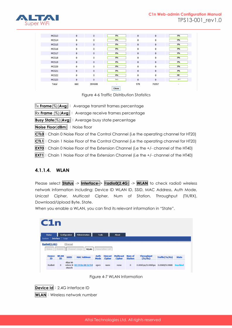
Figure 4-6 Traffic Distribution Statistics
Tx Frame(%)(Avg): Average transmit frames percentage
Rx Frame (%)(Avg): Average receive frames percentage
Busy State(%)(Avg):Average busy state percentage
Noise Floor(dBm) :Noise floor
CTL0:Chain 0 Noise Floor of the Control Channel (i.e the operating channel for HT20)
CTL1:Chain 1 Noise Floor of the Control Channel (i.e the operating channel for HT20)
EXT0:Chain 0 Noise Floor of the Extension Channel (i.e the +/- channel of the HT40)
EXT1:Chain 1 Noise Floor of the Extension Channel (i.e the +/- channel of the HT40)
4.1.1.4. WLAN
Please select Status -> Interface-> Radio0(2.4G) -> WLAN to check radio0 wireless
network information including: Device ID WLAN ID, SSID, MAC Address, Auth Mode,
Unicast Cipher, Multicast Cipher, Num of Station, Throughput (TX/RX),
Download/Upload Byte, State.
When you enable a WLAN, you can find its relevant information in “State”.
Figure 4-7 WLAN Information
Device Id:2.4G interface ID
WLAN:Wireless network number
Altai Technologies Ltd. All rights reserved
C1n Web-admin Configuration Manual
TPS13-001_rev1.0
SSID: C1n default SSID is Superwifi Network x (x is from 0 to 7)
MAC Address: 2.4G wireless network MAC address (BSSID)
Auth Mode: Authentication mode for each wireless network
Unicast Cipher :Unicast cipher mode for each wireless network
Multicast Cipher : Multicast cipher mode for each wireless network
Num of Station: Associated client number
Throughput(TX/RX):Real Throughput of transmitted and received packets for
each wireless network
Download/Upload Byte:Download and Upload packets for each wireless network
State:Wireless network state
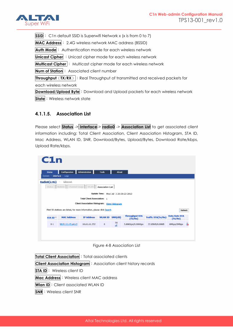
4.1.1.5. Association List
Please select Status -> Interface-> radio0 -> Association List to get associated client
information including: Total Client Association, Client Association Histogram, STA ID,
Mac Address, WLAN ID, SNR, Download/Bytes, Upload/Bytes, Download Rate/kbps,
Upload Rate/kbps.
Figure 4-8 Association List
Total Client Association:Total associated clients
Client Association Histogram:Association client history records
STA ID: Wireless client ID
Mac Address:Wireless client MAC address
Wlan ID:Client associated WLAN ID
SNR:Wireless client SNR

Altai Technologies Ltd. All rights reserved
C1n Web-admin Configuration Manual
TPS13-001_rev1.0
Throughput (Rx/Tx) :Wireless client real throughput received and transmitted traffic
(kbps)
Download/Upload Byte :Wireless client download and upload traffic (Bytes)
Download/Upload Rate :Wireless client download and upload rate (kbps)
Click this icon, below prompt will pop up. If choice the yes, the associated client
will be disconnected and added into rogue station list.
4.1.2. Ethernet Interface
Please select Status -> Interface-> Ethernet to check Ethernet interface information
including Status and Statistic.
4.1.2.1. Status
Please select Status -> Interface-> Ethernet -> Status to check Ethernet interface
status which includes Ethernet MAC Address, Speed, Duplex, Auto-negotiation and
Link Detected.
Figure 4-9 Ethernet Interface State
MAC Address: C1n Ethernet MAC address
Altai Technologies Ltd. All rights reserved
C1n Web-admin Configuration Manual
TPS13-001_rev1.0
Speed: C1n Ethernet speed
Duplex:C1n Ethernet duplex mode (Full/Half)
Auto-negotiation:C1n Ethernet auto-negotiation mode ON or OFF, by default it is
“ON”.
Link Detected:Whether C1n Ethernet do link detection, by default it is “yes”.
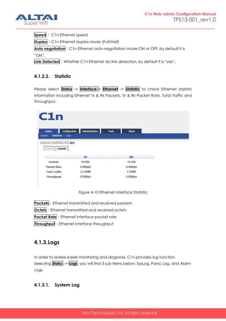
4.1.2.2. Statistic
Please select Status -> Interface-> Ethernet -> Statistic to check Ethernet statistic
information including Ethernet Tx & Rx Packets, Tx & Rx Packet Rate, Total Traffic and
Throughput.
Figure 4-10 Ethernet Interface Statistic
Packets:Ethernet transmitted and received packets
Octets:Ethernet transmitted and received octets
Packet Rate:Ethernet interface packet rate
Throughput:Ethernet interface throughput
4.1.3. Logs
In order to realize easier monitoring and diagnosis, C1n provides log function.
Selecting Status -> Logs, you will find 3 sub-items below: SysLog, Panic Log, and Alarm
Logs.
4.1.3.1. System Log
Altai Technologies Ltd. All rights reserved
C1n Web-admin Configuration Manual
TPS13-001_rev1.0
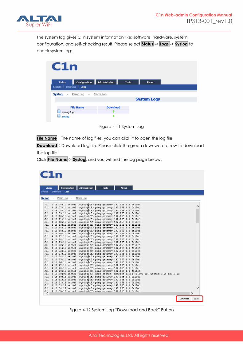
The system log gives C1n system information like: software, hardware, system
configuration, and self-checking result. Please select Status -> Logs -> Syslog to
check system log:
Figure 4-11 System Log
File Name:The name of log files, you can click it to open the log file.
Download:Download log file. Please click the green downward arrow to download
the log file.
Click File Name-> Syslog, and you will find the log page below:
Figure 4-12 System Log “Download and Back” Button
Altai Technologies Ltd. All rights reserved
C1n Web-admin Configuration Manual
TPS13-001_rev1.0
Please click Download to download the system log file and click Back at the end of
log to come back the previous page:
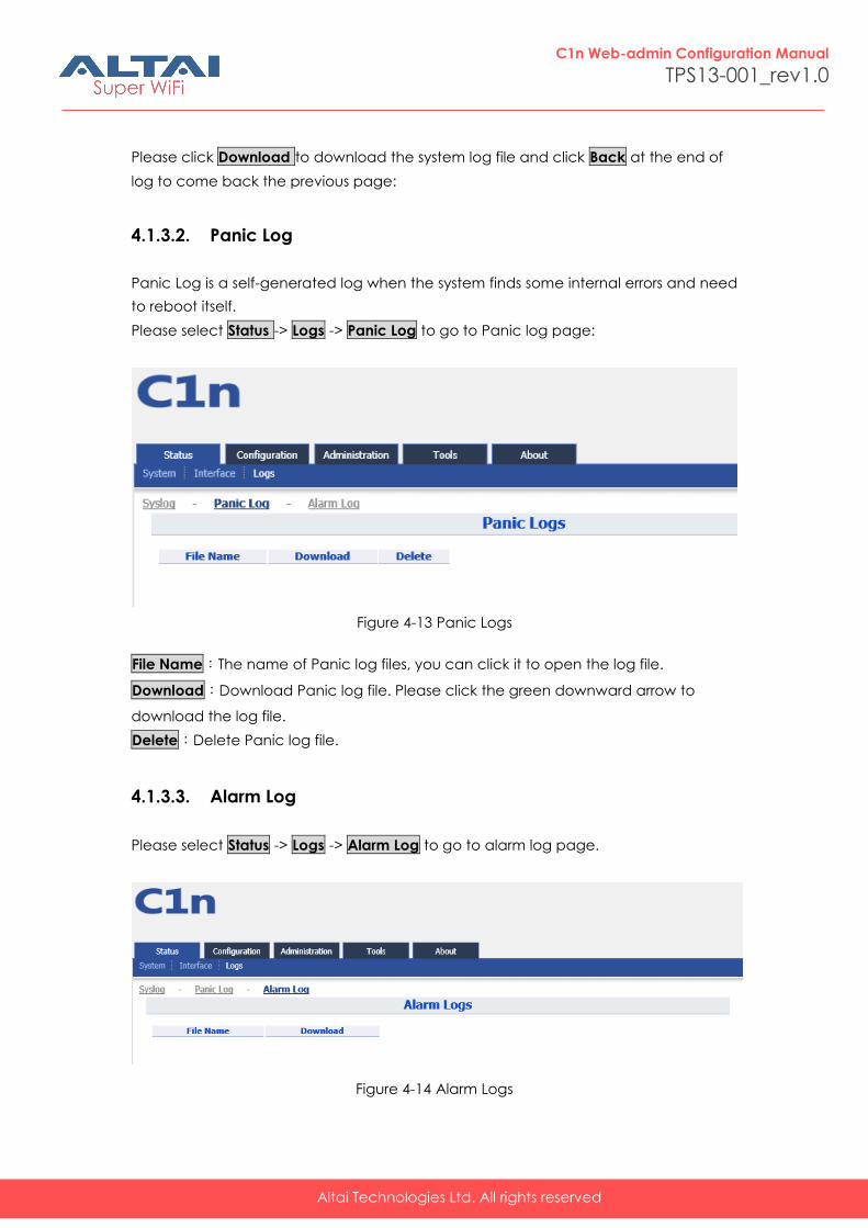
4.1.3.2. Panic Log
Panic Log is a self-generated log when the system finds some internal errors and need
to reboot itself.
Please select Status -> Logs -> Panic Log to go to Panic log page:
Figure 4-13 Panic Logs
File Name:The name of Panic log files, you can click it to open the log file.
Download:Download Panic log file. Please click the green downward arrow to
download the log file.
Delete:Delete Panic log file.
4.1.3.3. Alarm Log
Please select Status -> Logs -> Alarm Log to go to alarm log page.
Figure 4-14 Alarm Logs
Altai Technologies Ltd. All rights reserved
C1n Web-admin Configuration Manual
TPS13-001_rev1.0
File Name:The name of log files, you can click it to open the log file.
Download:Download log file. Please click the green downward arrow to download
the log file.
5. System Configuration
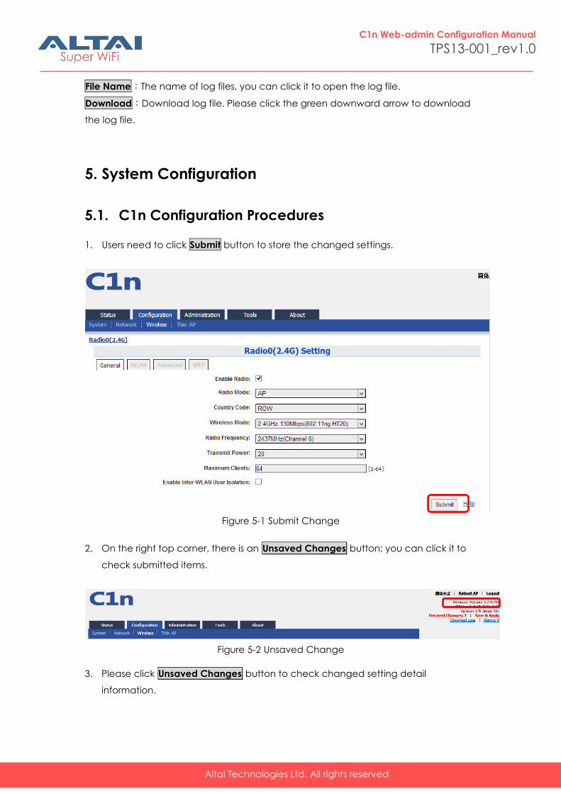
5.1. C1n Configuration Procedures
1. Users need to click Submit button to store the changed settings.
Figure 5-1 Submit Change
2. On the right top corner, there is an Unsaved Changes button; you can click it to
check submitted items.
Figure 5-2 Unsaved Change
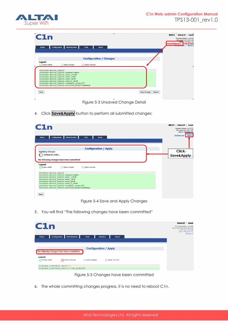
3. Please click Unsaved Changes button to check changed setting detail
information.
Altai Technologies Ltd. All rights reserved
C1n Web-admin Configuration Manual
TPS13-001_rev1.0
Figure 5-3 Unsaved Change Detail
4. Click Save&Apply button to perform all submitted changes:
Figure 5-4 Save and Apply Changes
5. You will find “The following changes have been committed”
Figure 5-5 Changes have been committed
6. The whole committing changes progress, it is no need to reboot C1n.
Altai Technologies Ltd. All rights reserved
C1n Web-admin Configuration Manual
TPS13-001_rev1.0
5.2. Basic Configuration
5.2.1. Basic System Configuration
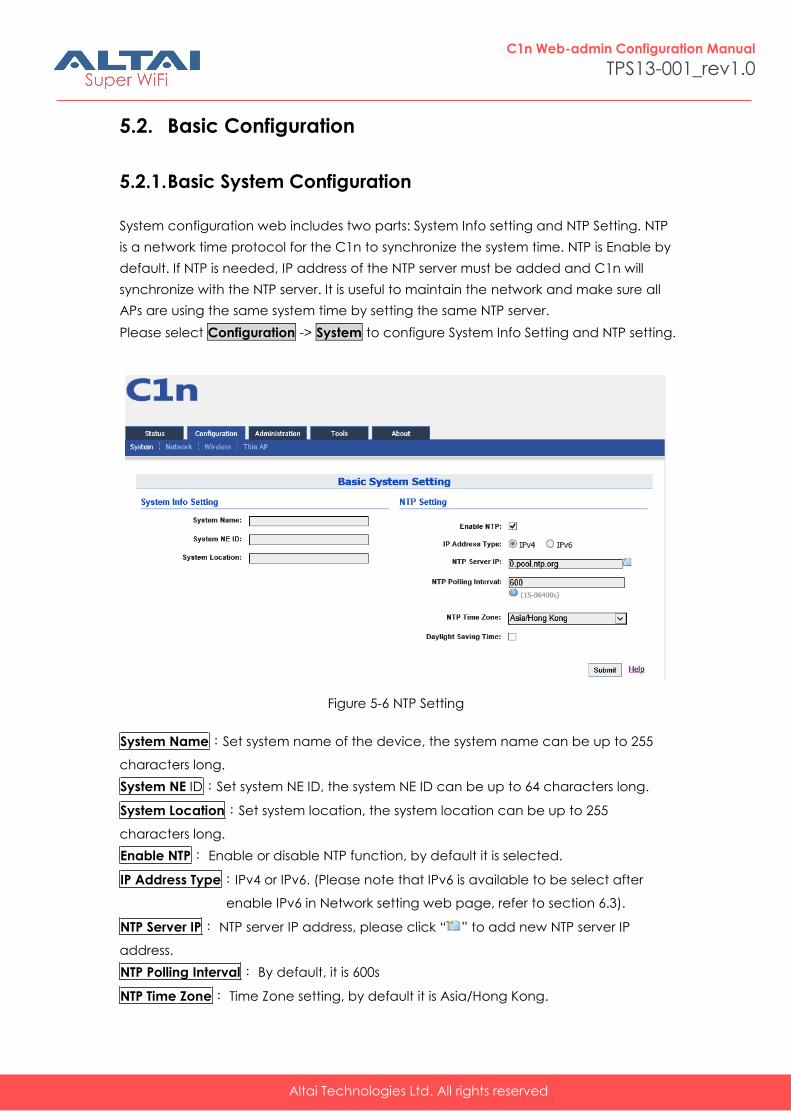
System configuration web includes two parts: System Info setting and NTP Setting. NTP
is a network time protocol for the C1n to synchronize the system time. NTP is Enable by
default. If NTP is needed, IP address of the NTP server must be added and C1n will
synchronize with the NTP server. It is useful to maintain the network and make sure all
APs are using the same system time by setting the same NTP server.
Please select Configuration -> System to configure System Info Setting and NTP setting.
Figure 5-6 NTP Setting
System Name:Set system name of the device, the system name can be up to 255
characters long.
System NE ID:Set system NE ID, the system NE ID can be up to 64 characters long.
System Location:Set system location, the system location can be up to 255
characters long.
Enable NTP: Enable or disable NTP function, by default it is selected.
IP Address Type:IPv4 or IPv6. (Please note that IPv6 is available to be select after
enable IPv6 in Network setting web page, refer to section 6.3).
NTP Server IP: NTP server IP address, please click “ ” to add new NTP server IP
address.
NTP Polling Interval: By default, it is 600s
NTP Time Zone: Time Zone setting, by default it is Asia/Hong Kong.
Altai Technologies Ltd. All rights reserved
C1n Web-admin Configuration Manual
TPS13-001_rev1.0
Daylight Saving Time: By default, it is not selected.
Procedures:
1. Select Configuration->System, to go to system setting page.
2. Type in the system information if it is needed.
3. Add NTP IP address in NTP Server IP.
4. Set NTP Polling Interval
5. Choose local NTP Time Zone
6. Set Daylight Saving Time(Optional)
7. Click Submit
8. Click Save&Apply to commit changes.
5.2.2. Network Configuration
Please select Configuration -> Network to go to Network configuration page.
5.2.2.1. General Network Configuration
Please select Configuration -> Network -> General and start to configure general
settings.
Altai Technologies Ltd. All rights reserved
C1n Web-admin Configuration Manual
TPS13-001_rev1.0
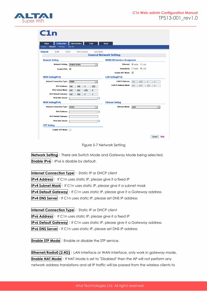
Figure 5-7 Network Setting
Network Setting:There are Switch Mode and Gateway Mode being selected.
Enable IPv6:IPv6 is disable by default.
Internet Connection Type: Static IP or DHCP client
IPv4 Address: If C1n uses static IP, please give it a fixed IP
IPv4 Subnet Mask:If C1n uses static IP, please give it a subnet mask
IPv4 Default Gateway:If C1n uses static IP, please give it a Gateway address
IPv4 DNS Server:If C1n uses static IP, please set DNS IP address
Internet Connection Type: Static IP or DHCP client
IPv6 Address: If C1n uses static IP, please give it a fixed IP
IPv6 Default Gateway:If C1n uses static IP, please give it a Gateway address
IPv6 DNS Server:If C1n uses static IP, please set DNS IP address
Enable STP Mode:Enable or disable the STP service.
Ethernet/Radio0 (2.4G):LAN interface or WAN interface, only work in gateway mode.
Enable NAT Mode:If NAT Mode is set to "Disabled" then the AP will not perform any
network address translations and all IP traffic will be passed from the wireless clients to
Altai Technologies Ltd. All rights reserved
C1n Web-admin Configuration Manual
TPS13-001_rev1.0
the DS (Ethernet) port or wireless bridge (802.11a radio) without any modification. If
NAT Mode is set to "Enabled" then the AP will perform network address translations on
all traffic being passed from the wireless clients to the DS ( Ethernet) port or wireless
bridge (802.11a radio). The NAT will translate IP traffic address's between the wireless
client subnet and the DS subnet.
LAN IP Address:IP address of local area network.
LAN IP Address Mask:IP address mask of local area network.
Ethernet Mode:Auto/manual mode.
Ethernet Duplex:AP Ethernet duplex mode (Full/Half).
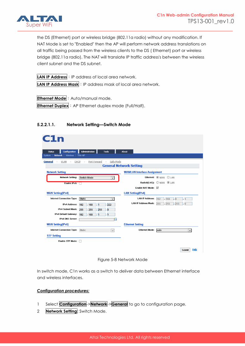
5.2.2.1.1. Network Setting—Switch Mode
Figure 5-8 Network Mode
In switch mode, C1n works as a switch to deliver data between Ethernet interface
and wireless interfaces.
Configuration procedures:
1 Select Configuration->Network->General to go to configuration page.
2 Network Setting: Switch Mode.
Altai Technologies Ltd. All rights reserved
C1n Web-admin Configuration Manual
TPS13-001_rev1.0
3 Click Submit.
4 Click Save&Apply to apply changes.
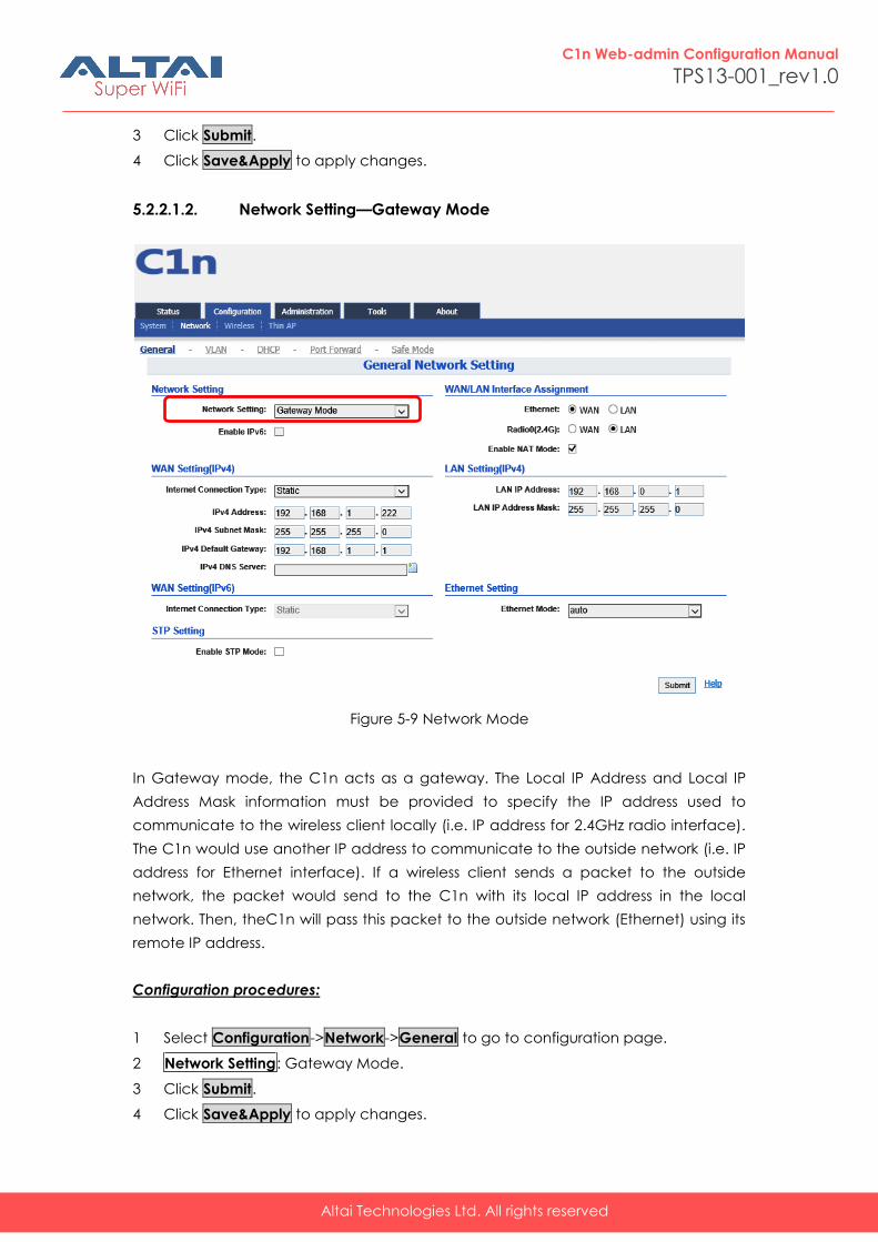
5.2.2.1.2. Network Setting—Gateway Mode
Figure 5-9 Network Mode
In Gateway mode, the C1n acts as a gateway. The Local IP Address and Local IP
Address Mask information must be provided to specify the IP address used to
communicate to the wireless client locally (i.e. IP address for 2.4GHz radio interface).
The C1n would use another IP address to communicate to the outside network (i.e. IP
address for Ethernet interface). If a wireless client sends a packet to the outside
network, the packet would send to the C1n with its local IP address in the local
network. Then, theC1n will pass this packet to the outside network (Ethernet) using its
remote IP address.
Configuration procedures:
1 Select Configuration->Network->General to go to configuration page.
2 Network Setting: Gateway Mode.
3 Click Submit.
4 Click Save&Apply to apply changes.
Altai Technologies Ltd. All rights reserved
C1n Web-admin Configuration Manual
TPS13-001_rev1.0
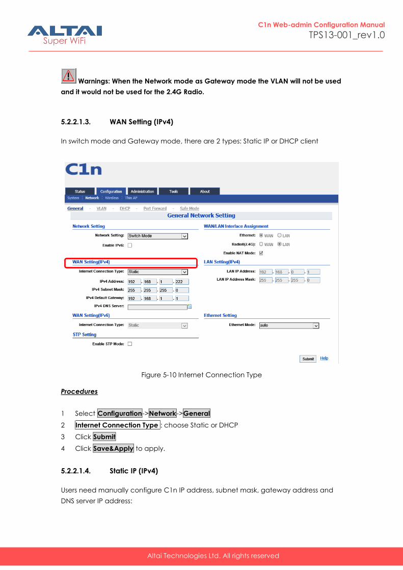
Warnings: When the Network mode as Gateway mode the VLAN will not be used
and it would not be used for the 2.4G Radio.
5.2.2.1.3. WAN Setting (IPv4)
In switch mode and Gateway mode, there are 2 types: Static IP or DHCP client
Figure 5-10 Internet Connection Type
Procedures
1 Select Configuration->Network->General
2 Internet Connection Type : choose Static or DHCP
3 Click Submit
4 Click Save&Apply to apply.
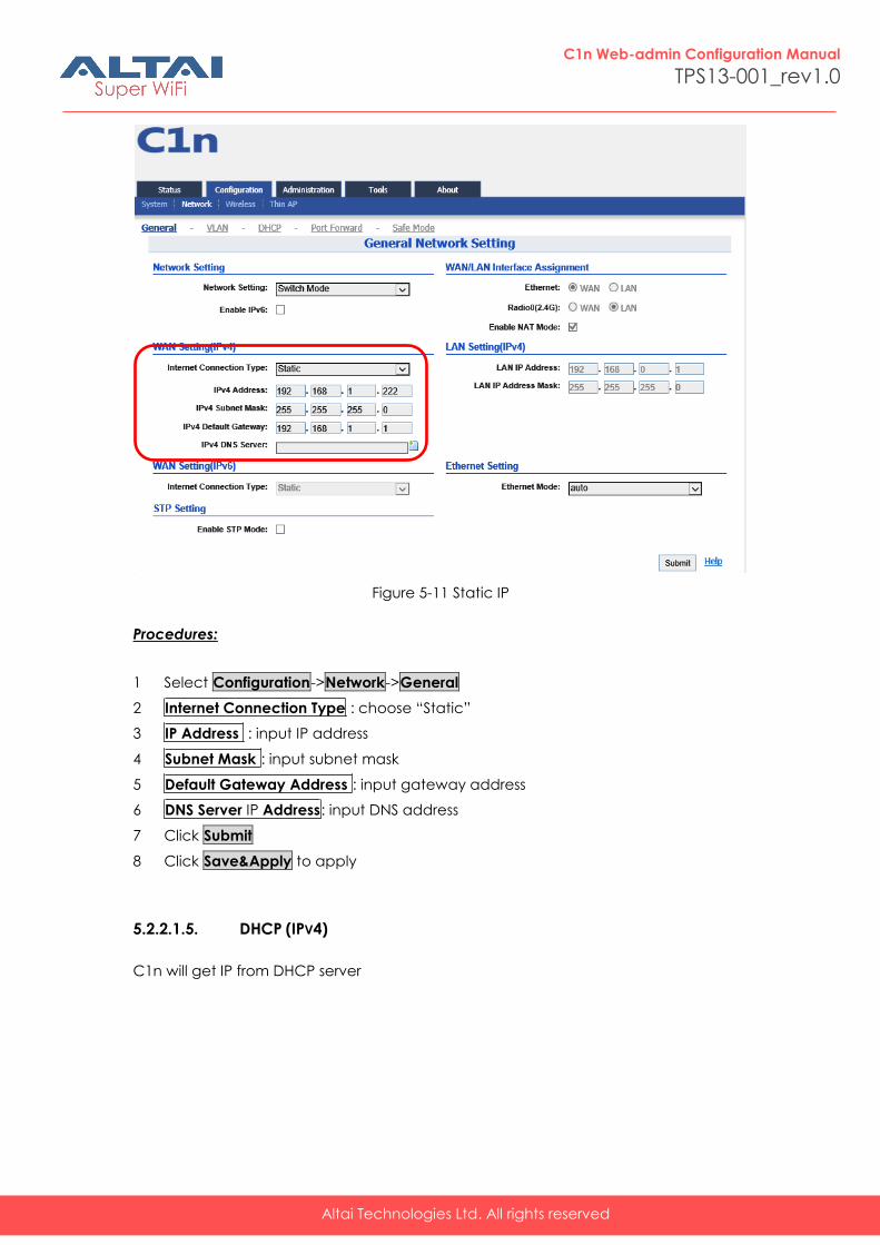
5.2.2.1.4. Static IP (IPv4)
Users need manually configure C1n IP address, subnet mask, gateway address and
DNS server IP address:
Altai Technologies Ltd. All rights reserved
C1n Web-admin Configuration Manual
TPS13-001_rev1.0
Figure 5-11 Static IP
Procedures:
1 Select Configuration->Network->General
2 Internet Connection Type : choose “Static”
3 IP Address : input IP address
4 Subnet Mask : input subnet mask
5 Default Gateway Address : input gateway address
6 DNS Server IP Address: input DNS address
7 Click Submit
8 Click Save&Apply to apply
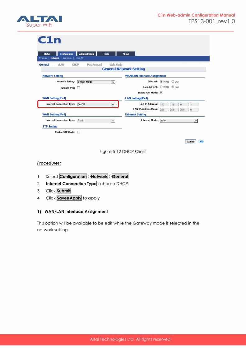
5.2.2.1.5. DHCP (IPV4)
C1n will get IP from DHCP server
Altai Technologies Ltd. All rights reserved
C1n Web-admin Configuration Manual
TPS13-001_rev1.0
Figure 5-12 DHCP Client
Procedures:
1 Select Configuration->Network->General
2 Internet Connection Type : choose DHCP;
3 Click Submit
4 Click Save&Apply to apply
1) WAN/LAN Interface Assignment
This option will be available to be edit while the Gateway mode is selected in the
network setting.
Altai Technologies Ltd. All rights reserved
C1n Web-admin Configuration Manual
TPS13-001_rev1.0
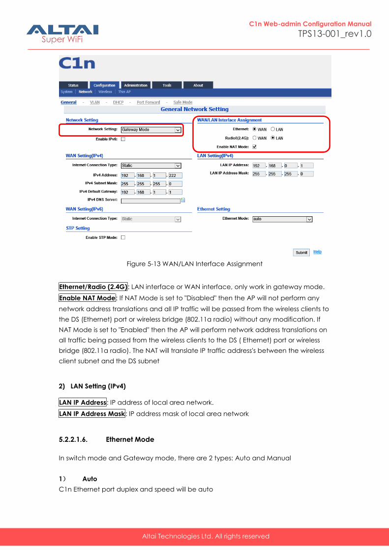
Figure 5-13 WAN/LAN Interface Assignment
Ethernet/Radio (2.4G): LAN interface or WAN interface, only work in gateway mode.
Enable NAT Mode: If NAT Mode is set to "Disabled" then the AP will not perform any
network address translations and all IP traffic will be passed from the wireless clients to
the DS (Ethernet) port or wireless bridge (802.11a radio) without any modification. If
NAT Mode is set to "Enabled" then the AP will perform network address translations on
all traffic being passed from the wireless clients to the DS ( Ethernet) port or wireless
bridge (802.11a radio). The NAT will translate IP traffic address's between the wireless
client subnet and the DS subnet
2) LAN Setting (IPv4)
LAN IP Address: IP address of local area network.
LAN IP Address Mask: IP address mask of local area network
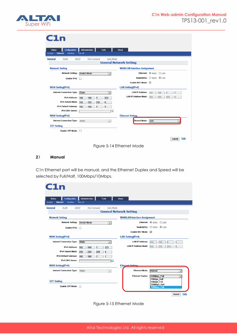
5.2.2.1.6. Ethernet Mode
In switch mode and Gateway mode, there are 2 types: Auto and Manual
1) Auto
C1n Ethernet port duplex and speed will be auto
Altai Technologies Ltd. All rights reserved
C1n Web-admin Configuration Manual
TPS13-001_rev1.0
Figure 5-14 Ethernet Mode
2) Manual
C1n Ethernet port will be manual, and the Ethernet Duplex and Speed will be
selected by Full/Half, 100Mbps/10Mbps.
Figure 5-15 Ethernet Mode
Altai Technologies Ltd. All rights reserved
C1n Web-admin Configuration Manual
TPS13-001_rev1.0
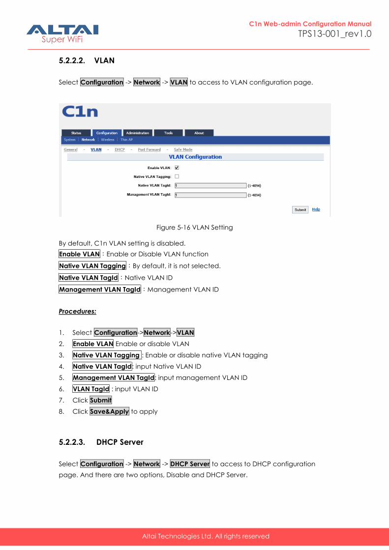
5.2.2.2. VLAN
Select Configuration -> Network -> VLAN to access to VLAN configuration page.
Figure 5-16 VLAN Setting
By default, C1n VLAN setting is disabled.
Enable VLAN:Enable or Disable VLAN function
Native VLAN Tagging:By default, it is not selected.
Native VLAN TagId:Native VLAN ID
Management VLAN TagId:Management VLAN ID
Procedures:
1. Select Configuration->Network->VLAN
2. Enable VLAN Enable or disable VLAN
3. Native VLAN Tagging : Enable or disable native VLAN tagging
4. Native VLAN TagId: input Native VLAN ID
5. Management VLAN TagId: input management VLAN ID
6. VLAN TagId : input VLAN ID
7. Click Submit
8. Click Save&Apply to apply
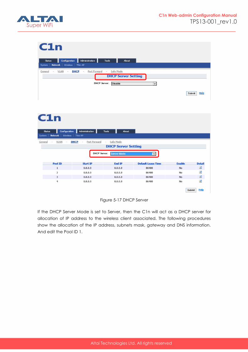
5.2.2.3. DHCP Server
Select Configuration -> Network -> DHCP Server to access to DHCP configuration
page. And there are two options, Disable and DHCP Server.
Altai Technologies Ltd. All rights reserved
C1n Web-admin Configuration Manual
TPS13-001_rev1.0
Figure 5-17 DHCP Server
If the DHCP Server Mode is set to Server, then the C1n will act as a DHCP server for
allocation of IP address to the wireless client associated. The following procedures
show the allocation of the IP address, subnets mask, gateway and DNS information.
And edit the Pool ID 1.
Altai Technologies Ltd. All rights reserved
C1n Web-admin Configuration Manual
TPS13-001_rev1.0
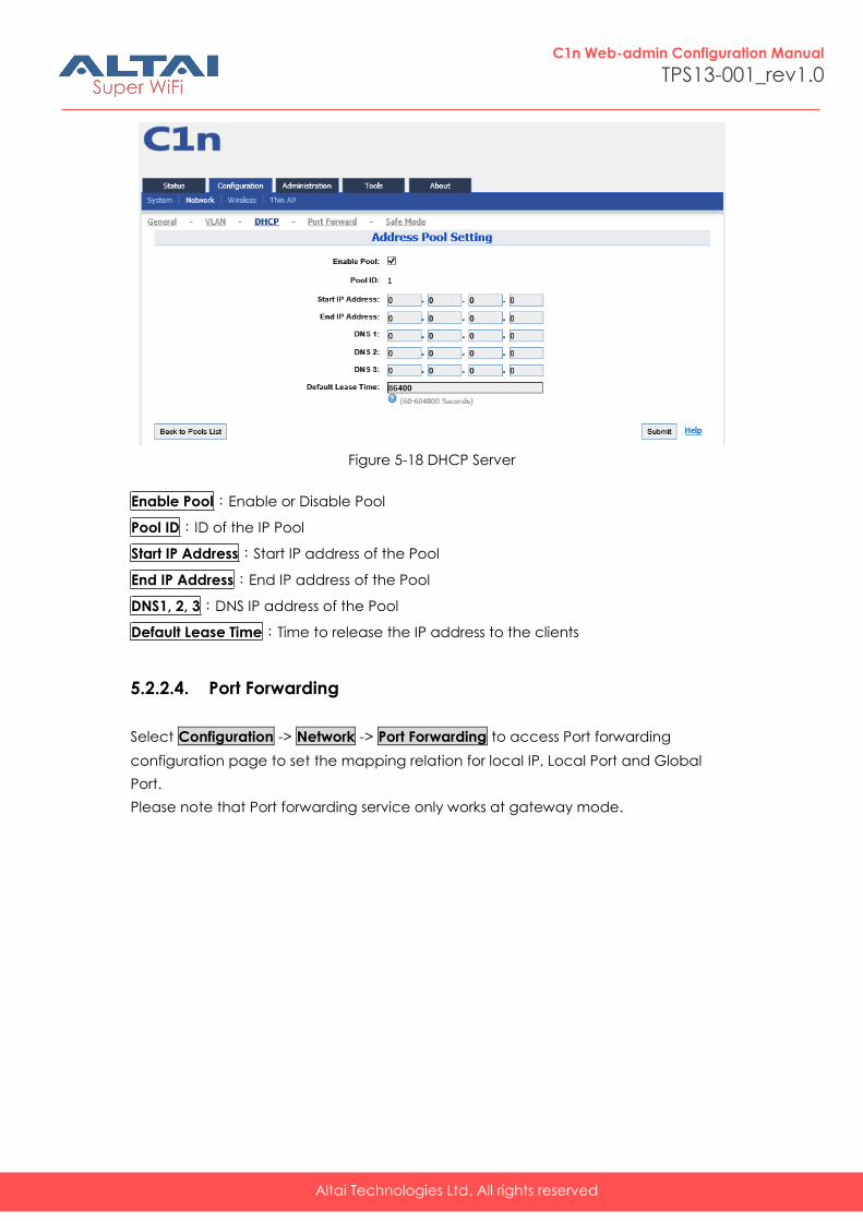
Figure 5-18 DHCP Server
Enable Pool:Enable or Disable Pool
Pool ID:ID of the IP Pool
Start IP Address:Start IP address of the Pool
End IP Address:End IP address of the Pool
DNS1, 2, 3:DNS IP address of the Pool
Default Lease Time:Time to release the IP address to the clients
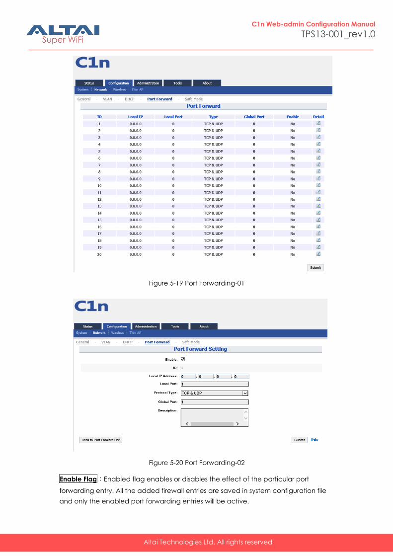
5.2.2.4. Port Forwarding
Select Configuration -> Network -> Port Forwarding to access Port forwarding
configuration page to set the mapping relation for local IP, Local Port and Global
Port.
Please note that Port forwarding service only works at gateway mode.
Altai Technologies Ltd. All rights reserved
C1n Web-admin Configuration Manual
TPS13-001_rev1.0
Figure 5-19 Port Forwarding-01
Figure 5-20 Port Forwarding-02
Enable Flag:Enabled flag enables or disables the effect of the particular port
forwarding entry. All the added firewall entries are saved in system configuration file
and only the enabled port forwarding entries will be active.
Altai Technologies Ltd. All rights reserved
C1n Web-admin Configuration Manual
TPS13-001_rev1.0
Local IP Address:This control is used to specify the host which is connected to the
internal network and needs to be accessible from the external network.
Local Port:This control is used to specify the TCP/UDP port of the application running
on the host which is connected to the internal network. The specified port will be
accessible from the external network.
Protocol Type:This control is used to specify the L3 protocol (IP) type which need to
be forwarded from the internal network.
Global Port:This control is used to specify the TCP/UDP port of the C1n Wi-Fi Access
Point/Bridge based device which will accept and forward the connections from the
external network to the host connected to the internal network.
Description:This control is used to specify informal field for the comment of the
particular port forwarding entry. Few words about the particular port forwarding entry
purpose are saved there usually.
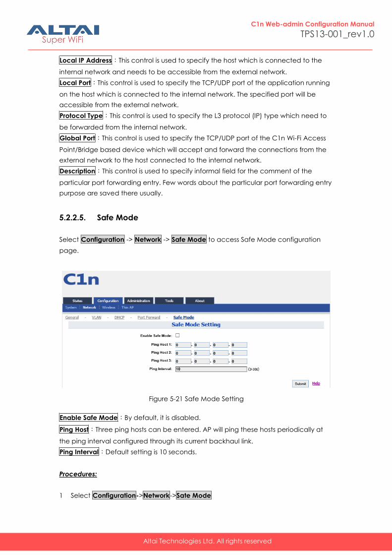
5.2.2.5. Safe Mode
Select Configuration -> Network -> Safe Mode to access Safe Mode configuration
page.
Figure 5-21 Safe Mode Setting
Enable Safe Mode:By default, it is disabled.
Ping Host:Three ping hosts can be entered. AP will ping these hosts periodically at
the ping interval configured through its current backhaul link.
Ping Interval:Default setting is 10 seconds.
Procedures:
1 Select Configuration->Network->Sate Mode
Altai Technologies Ltd. All rights reserved
C1n Web-admin Configuration Manual
TPS13-001_rev1.0
2 Enable Safe Mode: Select it to enable safe mode function. By default, it is
disabled.
3 Ping Host: at least input one host
4 Ping Interval: input the interval of ping
5 Click Submit
6 Click Save&Apply to apply
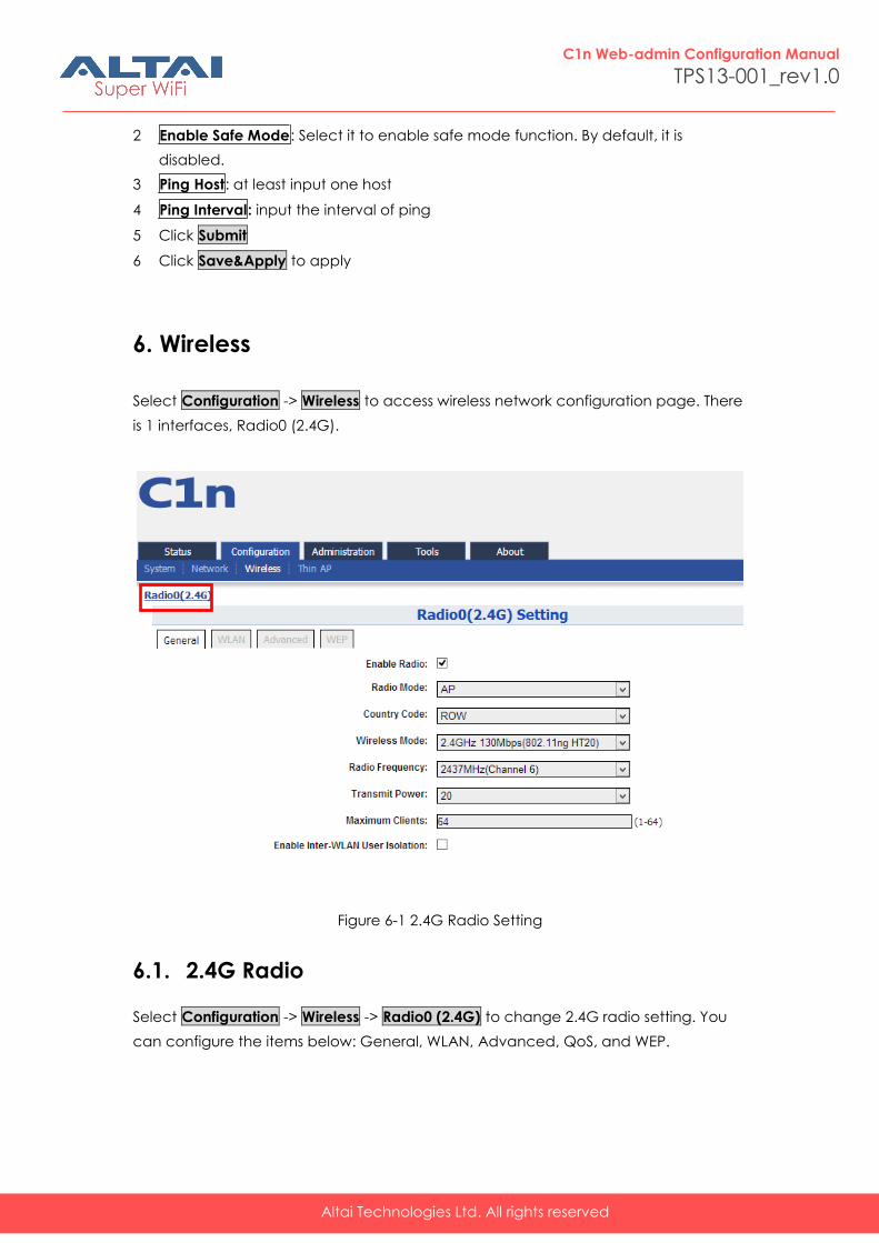
6. Wireless
Select Configuration -> Wireless to access wireless network configuration page. There
is 1 interfaces, Radio0 (2.4G).
Figure 6-1 2.4G Radio Setting
6.1. 2.4G Radio
Select Configuration -> Wireless -> Radio0 (2.4G) to change 2.4G radio setting. You
can configure the items below: General, WLAN, Advanced, QoS, and WEP.
Altai Technologies Ltd. All rights reserved
C1n Web-admin Configuration Manual
TPS13-001_rev1.0
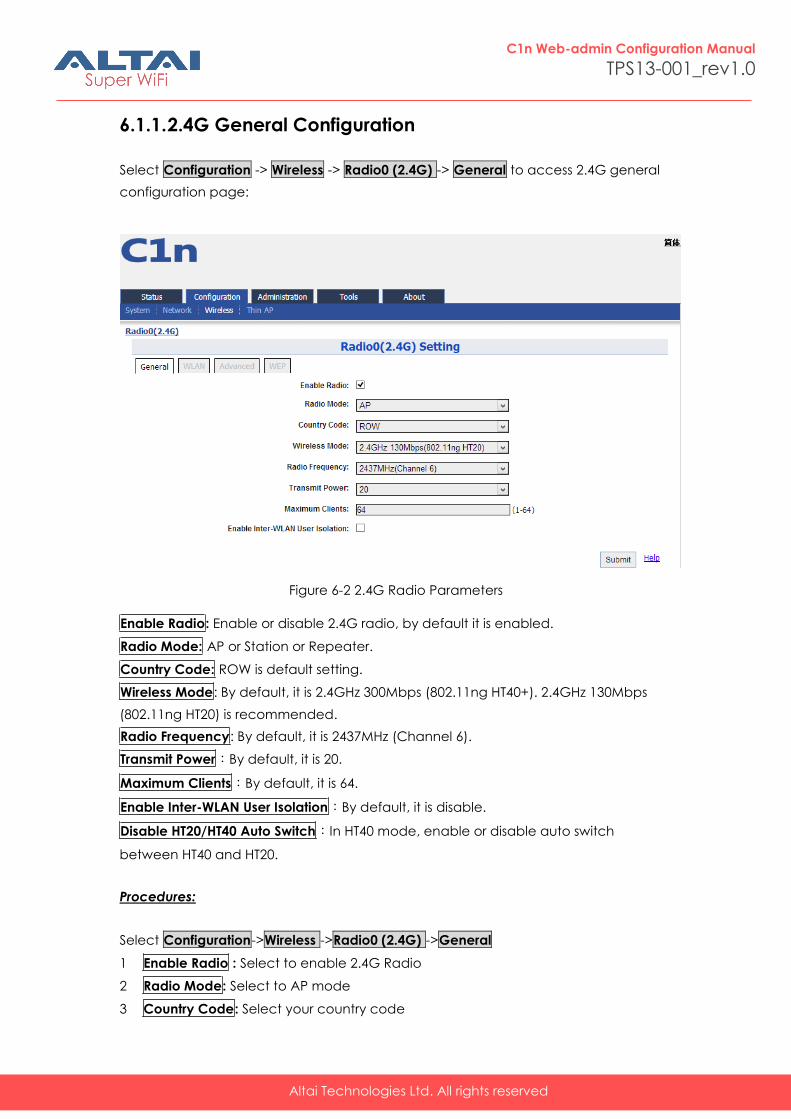
6.1.1. 2.4G General Configuration
Select Configuration -> Wireless -> Radio0 (2.4G) -> General to access 2.4G general
configuration page:
Figure 6-2 2.4G Radio Parameters
Enable Radio: Enable or disable 2.4G radio, by default it is enabled.
Radio Mode: AP or Station or Repeater.
Country Code: ROW is default setting.
Wireless Mode: By default, it is 2.4GHz 300Mbps (802.11ng HT40+). 2.4GHz 130Mbps
(802.11ng HT20) is recommended.
Radio Frequency: By default, it is 2437MHz (Channel 6).
Transmit Power:By default, it is 20.
Maximum Clients:By default, it is 64.
Enable Inter-WLAN User Isolation:By default, it is disable.
Disable HT20/HT40 Auto Switch:In HT40 mode, enable or disable auto switch
between HT40 and HT20.
Procedures:
Select Configuration->Wireless ->Radio0 (2.4G) ->General
1 Enable Radio : Select to enable 2.4G Radio
2 Radio Mode: Select to AP mode
3 Country Code: Select your country code
Altai Technologies Ltd. All rights reserved
C1n Web-admin Configuration Manual
TPS13-001_rev1.0
4 Wireless Mode Select wireless mode
5 Transmit Power Set transmit power
6 Maximum Clients Set 2.4G maximum clients
7 Click Submit
8 Click Save&Apply to apply
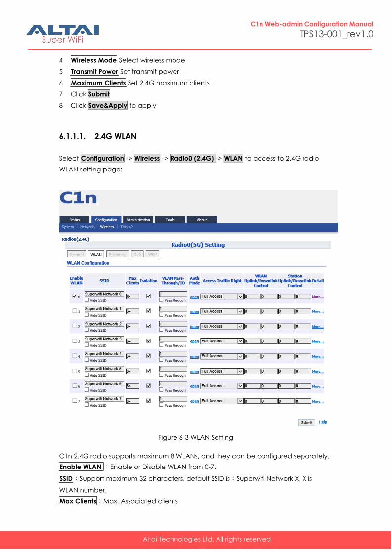
6.1.1.1. 2.4G WLAN
Select Configuration -> Wireless -> Radio0 (2.4G) -> WLAN to access to 2.4G radio
WLAN setting page:
Figure 6-3 WLAN Setting
C1n 2.4G radio supports maximum 8 WLANs, and they can be configured separately.
Enable WLAN :Enable or Disable WLAN from 0-7.
SSID:Support maximum 32 characters, default SSID is:Superwifi Network X, X is
WLAN number.
Max Clients:Max. Associated clients
Altai Technologies Ltd. All rights reserved
C1n Web-admin Configuration Manual
TPS13-001_rev1.0
Isolation: Enable or Disable inter-WLAN communication isolation. By default, it is
enable.
VLAN Pass-Through/ID: Set VLAN pass through or VLAN TagID this WLAN
Access Traffic Right:Access traffic right controls associated stations the
ability to permit or deny AP management.
WLAN Uplink/Downlink Control: This option control the uplink and downlink speed for
this WLAN.
Station Uplink/Downlink Control: This option control the uplink and downlink speed
for the stations which associate to this WLAN.
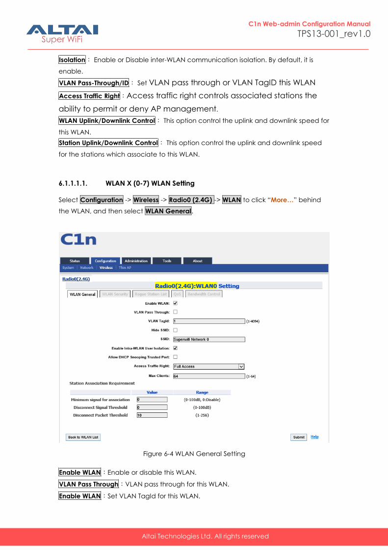
6.1.1.1.1. WLAN X (0-7) WLAN Setting
Select Configuration -> Wireless -> Radio0 (2.4G) -> WLAN to click “More…” behind
the WLAN, and then select WLAN General.
Figure 6-4 WLAN General Setting
Enable WLAN:Enable or disable this WLAN.
VLAN Pass Through:VLAN pass through for this WLAN.
Enable WLAN:Set VLAN TagId for this WLAN.
Altai Technologies Ltd. All rights reserved
C1n Web-admin Configuration Manual
TPS13-001_rev1.0
Hide SSID:Hide this SSID or not.
SSID:Set SSID name.
Allow Intra-WLAN User Isolation:Allow or block intra-WLAN user communication. By
default, it is enable.
Allow DHCP Snooping Trusted Port:DHCP snooping prevents illegal DHCP servers
from offering IP address on untrusted wireless port.
Access Traffic Right:Access traffic right controls associated stations the ability to
permit or deny AP management.
Max Clients:Maximum value is 64.
Minimum signal for association: Set the minimum signal value (SNR) for client can
associate to this WLAN. The range is 0~100dB, and 0 means disable.
Disconnect Signal Threshold:Set the signal threshold value (SNR) for client to
disconnect to this WLAN.
Disconnect Packet Threshold:Set the packet threshold value (SNR) for client to
disconnect to this WLAN.
Back to WLAN List:Go back to previous page
Procedures:
1. Select Configuration -> Wireless -> Radio0 (2.4G) -> WLAN to click “More…”
behind the WLAN, and then select WLAN General.
2. Enable WLAN select to enable this WLAN
3. VLAN Pass Through allow or don’t allow VLAN pass through
4. VLAN TagId Set VLAN ID
5. SSID set SSID
6. Allow Intra-WLAN User Isolation: Allow or block intra-WLAN User communication.
7. Max Clients Maximum is 64
8. Click Submit
9. Click Save&Apply to apply
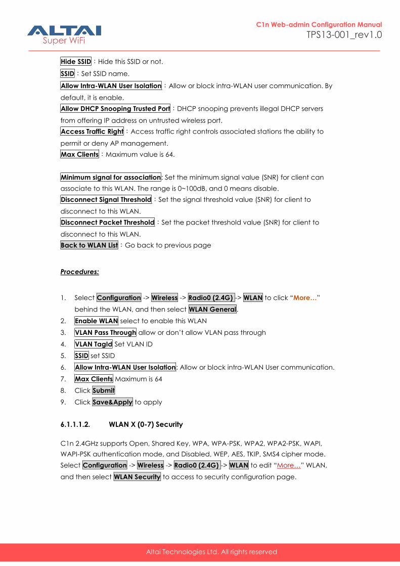
6.1.1.1.2. WLAN X (0-7) Security
C1n 2.4GHz supports Open, Shared Key, WPA, WPA-PSK, WPA2, WPA2-PSK, WAPI,
WAPI-PSK authentication mode, and Disabled, WEP, AES, TKIP, SMS4 cipher mode.
Select Configuration -> Wireless -> Radio0 (2.4G) -> WLAN to edit “More…” WLAN,
and then select WLAN Security to access to security configuration page.
Altai Technologies Ltd. All rights reserved
C1n Web-admin Configuration Manual
TPS13-001_rev1.0
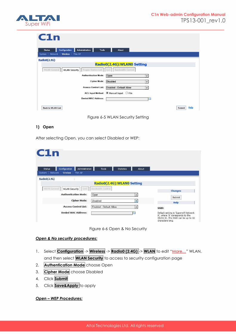
Figure 6-5 WLAN Security Setting
1) Open
After selecting Open, you can select Disabled or WEP:
Figure 6-6 Open & No Security
Open & No security procedures:
1. Select Configuration -> Wireless -> Radio0 (2.4G) -> WLAN to edit “More…” WLAN,
and then select WLAN Security to access to security configuration page
2. Authentication Mode choose Open
3. Cipher Mode choose Disabled
4. Click Submit
5. Click Save&Apply to apply
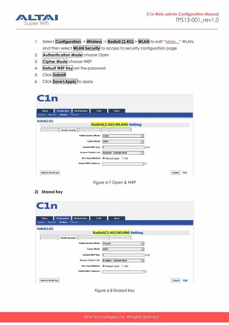
Open – WEP Procedures:
Altai Technologies Ltd. All rights reserved
C1n Web-admin Configuration Manual
TPS13-001_rev1.0
1. Select Configuration -> Wireless -> Radio0 (2.4G)-> WLAN to edit “More…” WLAN,
and then select WLAN Security to access to security configuration page
2. Authentication Mode choose Open
3. Cipher Mode choose WEP
4. Default WEP Key set the password
5. Click Submit
6. Click Save&Apply to apply
Figure 6-7 Open & WEP
2) Shared Key
Figure 6-8 Shared Key
Altai Technologies Ltd. All rights reserved
C1n Web-admin Configuration Manual
TPS13-001_rev1.0
Shared key Procedures:
1. Select Configuration -> Wireless -> Radio0 (2.4G)-> WLAN to edit “More…” WLAN,
and then select WLAN Security to access to security configuration page
2. Authentication Mode choose Shared
3. Cipher Mode choose WEP
4. Default WEP Key set the password
5. Click Submit
6. Click Save&Apply to apply
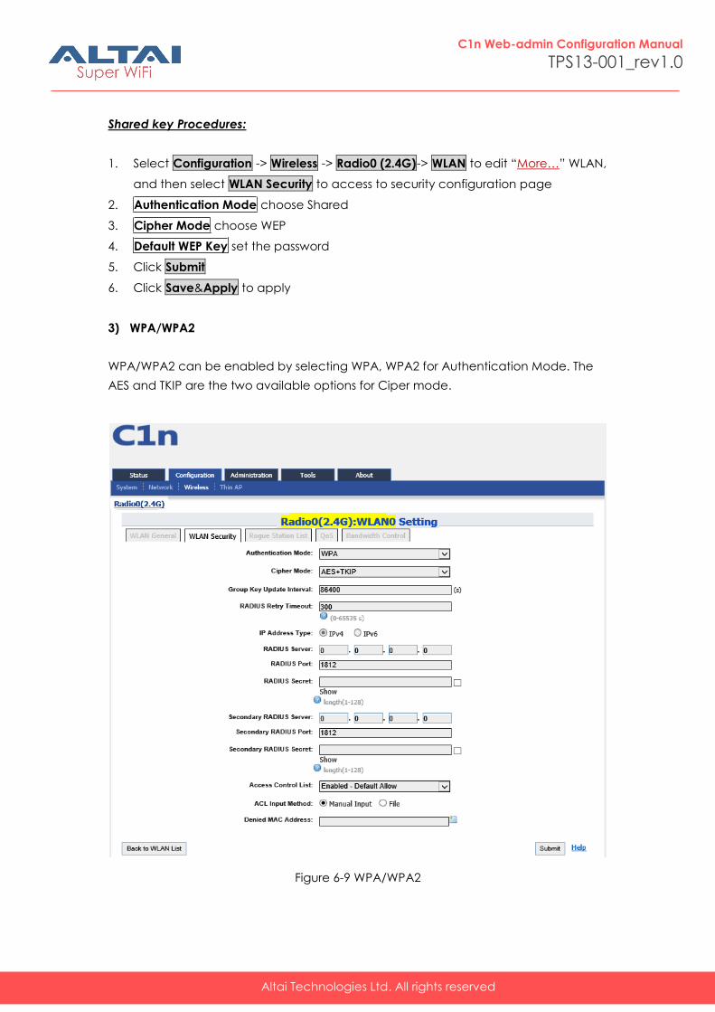
3) WPA/WPA2
WPA/WPA2 can be enabled by selecting WPA, WPA2 for Authentication Mode. The
AES and TKIP are the two available options for Ciper mode.
Figure 6-9 WPA/WPA2
Altai Technologies Ltd. All rights reserved
C1n Web-admin Configuration Manual
TPS13-001_rev1.0
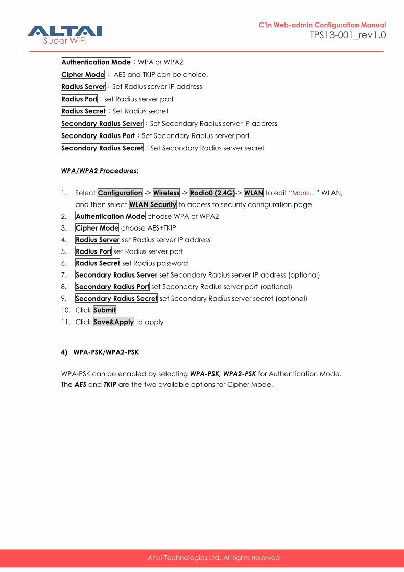
Authentication Mode:WPA or WPA2
Cipher Mode: AES and TKIP can be choice.
Radius Server:Set Radius server IP address
Radius Port:set Radius server port
Radius Secret:Set Radius secret
Secondary Radius Server:Set Secondary Radius server IP address
Secondary Radius Port:Set Secondary Radius server port
Secondary Radius Secret:Set Secondary Radius server secret
WPA/WPA2 Procedures:
1. Select Configuration -> Wireless -> Radio0 (2.4G)-> WLAN to edit “More…” WLAN,
and then select WLAN Security to access to security configuration page
2. Authentication Mode choose WPA or WPA2
3. Cipher Mode choose AES+TKIP
4. Radius Server set Radius server IP address
5. Radius Port set Radius server port
6. Radius Secret set Radius password
7. Secondary Radius Server set Secondary Radius server IP address (optional)
8. Secondary Radius Port set Secondary Radius server port (optional)
9. Secondary Radius Secret set Secondary Radius server secret (optional)
10. Click Submit
11. Click Save&Apply to apply
4) WPA-PSK/WPA2-PSK
WPA-PSK can be enabled by selecting WPA-PSK, WPA2-PSK for Authentication Mode.
The AES and TKIP are the two available options for Cipher Mode.
Altai Technologies Ltd. All rights reserved
C1n Web-admin Configuration Manual
TPS13-001_rev1.0
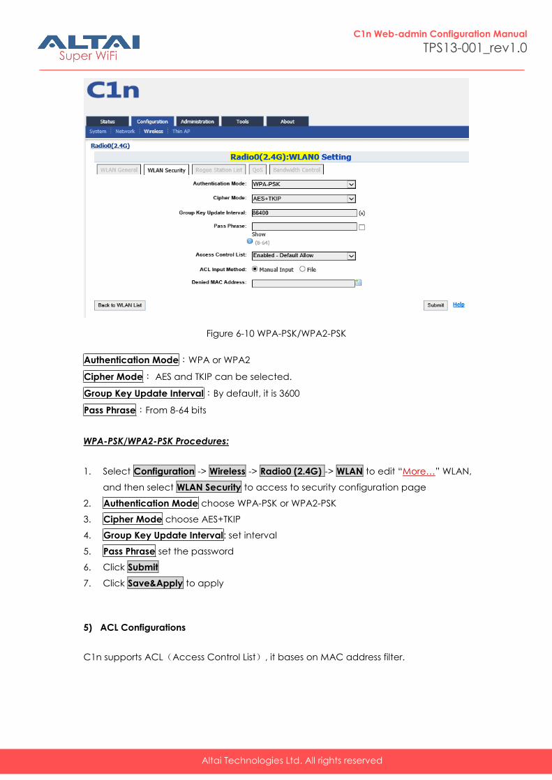
Figure 6-10 WPA-PSK/WPA2-PSK
Authentication Mode:WPA or WPA2
Cipher Mode: AES and TKIP can be selected.
Group Key Update Interval:By default, it is 3600
Pass Phrase:From 8-64 bits
WPA-PSK/WPA2-PSK Procedures:
1. Select Configuration -> Wireless -> Radio0 (2.4G) -> WLAN to edit “More…” WLAN,
and then select WLAN Security to access to security configuration page
2. Authentication Mode choose WPA-PSK or WPA2-PSK
3. Cipher Mode choose AES+TKIP
4. Group Key Update Interval: set interval
5. Pass Phrase set the password
6. Click Submit
7. Click Save&Apply to apply
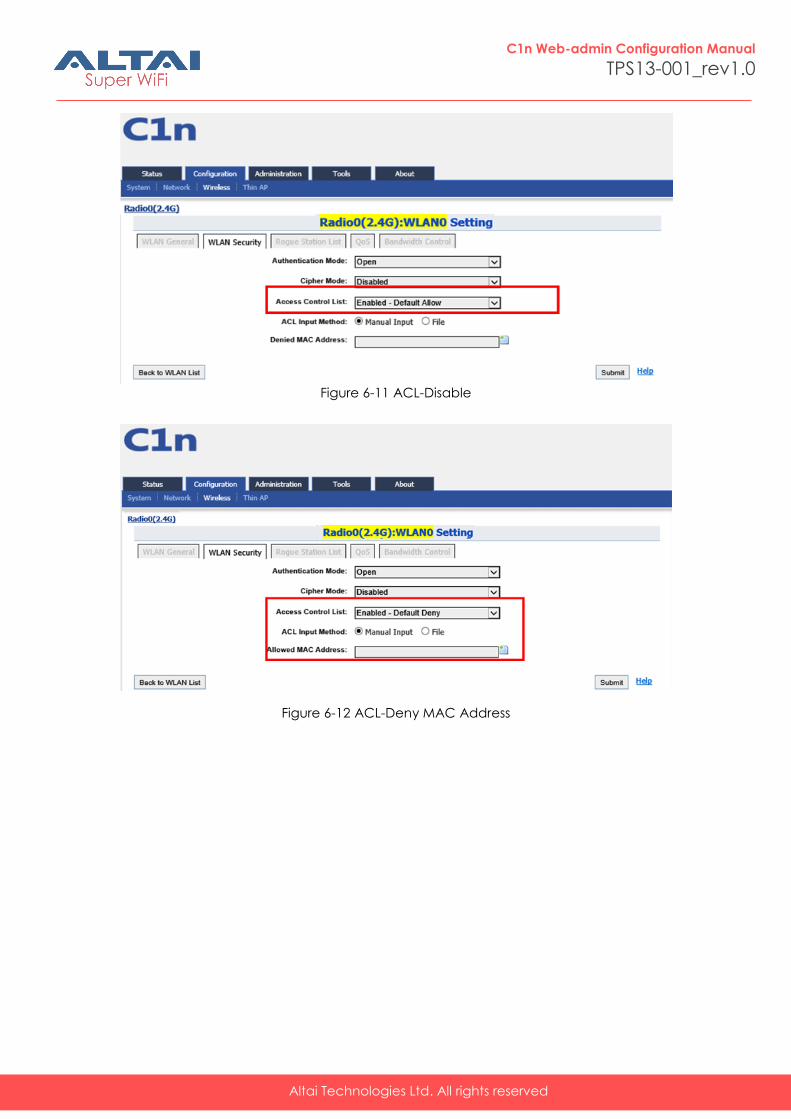
5) ACL Configurations
C1n supports ACL(Access Control List), it bases on MAC address filter.
Altai Technologies Ltd. All rights reserved
C1n Web-admin Configuration Manual
TPS13-001_rev1.0
Figure 6-11 ACL-Disable
Figure 6-12 ACL-Deny MAC Address
Altai Technologies Ltd. All rights reserved
C1n Web-admin Configuration Manual
TPS13-001_rev1.0
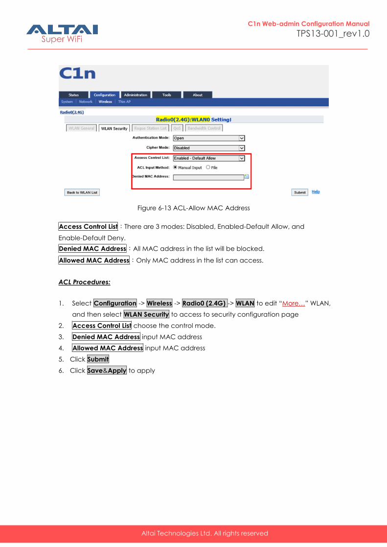
Figure 6-13 ACL-Allow MAC Address
Access Control List:There are 3 modes: Disabled, Enabled-Default Allow, and
Enable-Default Deny.
Denied MAC Address:All MAC address in the list will be blocked.
Allowed MAC Address:Only MAC address in the list can access.
ACL Procedures:
1. Select Configuration -> Wireless -> Radio0 (2.4G) -> WLAN to edit “More…” WLAN,
and then select WLAN Security to access to security configuration page
2. Access Control List choose the control mode.
3. Denied MAC Address input MAC address
4. Allowed MAC Address input MAC address
5. Click Submit
6. Click Save&Apply to apply
Altai Technologies Ltd. All rights reserved
C1n Web-admin Configuration Manual
TPS13-001_rev1.0
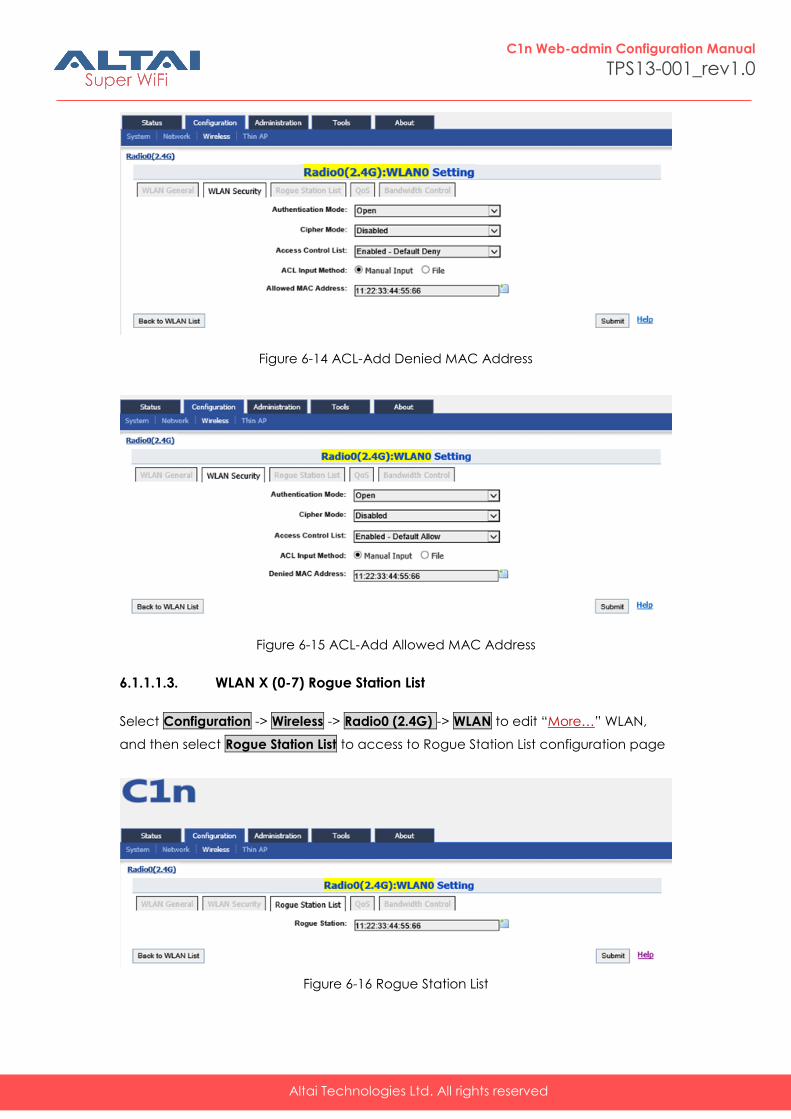
Figure 6-14 ACL-Add Denied MAC Address
Figure 6-15 ACL-Add Allowed MAC Address
6.1.1.1.3. WLAN X (0-7) Rogue Station List
Select Configuration -> Wireless -> Radio0 (2.4G) -> WLAN to edit “More…” WLAN,
and then select Rogue Station List to access to Rogue Station List configuration page
Figure 6-16 Rogue Station List
Altai Technologies Ltd. All rights reserved
C1n Web-admin Configuration Manual
TPS13-001_rev1.0
Rogue Station:Type in the MAC address of rogue station.
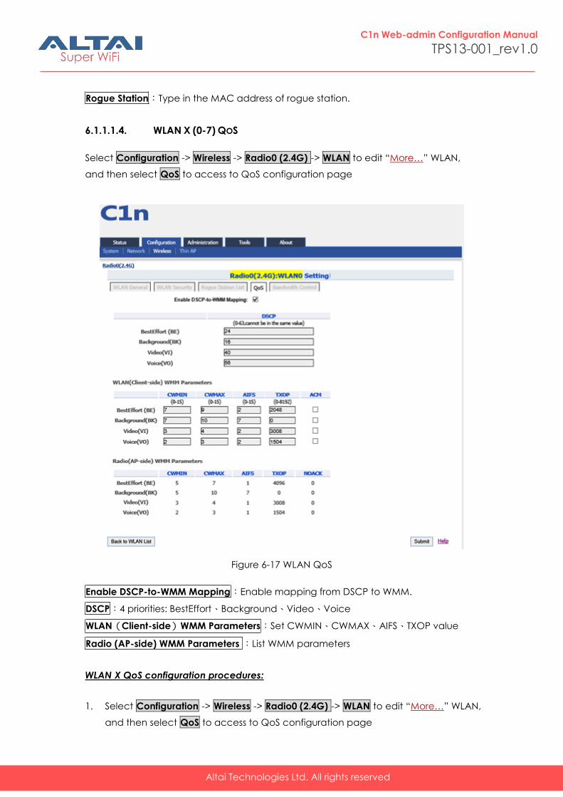
6.1.1.1.4. WLAN X (0-7) QOS
Select Configuration -> Wireless -> Radio0 (2.4G) -> WLAN to edit “More…” WLAN,
and then select QoS to access to QoS configuration page
Figure 6-17 WLAN QoS
Enable DSCP-to-WMM Mapping:Enable mapping from DSCP to WMM.
DSCP:4 priorities: BestEffort、Background、Video、Voice
WLAN(Client-side)WMM Parameters:Set CWMIN、CWMAX、AIFS、TXOP value
Radio (AP-side) WMM Parameters :List WMM parameters
WLAN X QoS configuration procedures:
1. Select Configuration -> Wireless -> Radio0 (2.4G) -> WLAN to edit “More…” WLAN,
and then select QoS to access to QoS configuration page
Altai Technologies Ltd. All rights reserved
C1n Web-admin Configuration Manual
TPS13-001_rev1.0
2. Enable DSCP-to-WMM Mapping (optional)
3. DSCP choose one of priorities
4. WLAN(Client-side)WMM Parameters Set CWMIN、CWMAX、AIFS、TXOP value
5. Click Submit
6. Click Save&Apply to apply
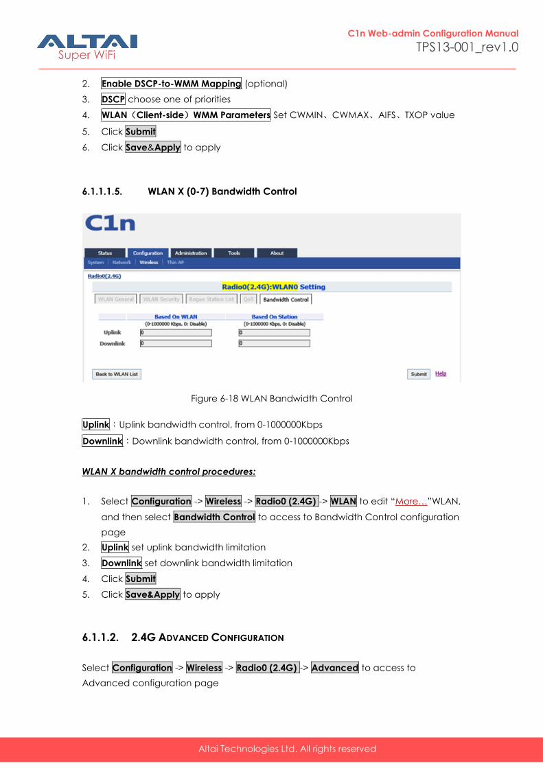
6.1.1.1.5. WLAN X (0-7) Bandwidth Control
Figure 6-18 WLAN Bandwidth Control
Uplink:Uplink bandwidth control, from 0-1000000Kbps
Downlink:Downlink bandwidth control, from 0-1000000Kbps
WLAN X bandwidth control procedures:
1. Select Configuration -> Wireless -> Radio0 (2.4G) -> WLAN to edit “More…”WLAN,
and then select Bandwidth Control to access to Bandwidth Control configuration
page
2. Uplink set uplink bandwidth limitation
3. Downlink set downlink bandwidth limitation
4. Click Submit
5. Click Save&Apply to apply
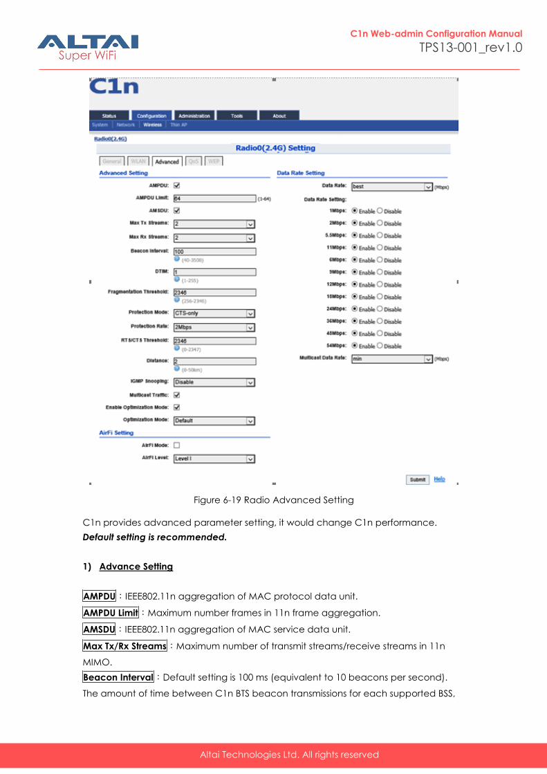
6.1.1.2. 2.4G ADVANCED CONFIGURATION
Select Configuration -> Wireless -> Radio0 (2.4G) -> Advanced to access to
Advanced configuration page
Altai Technologies Ltd. All rights reserved
C1n Web-admin Configuration Manual
TPS13-001_rev1.0
Figure 6-19 Radio Advanced Setting
C1n provides advanced parameter setting, it would change C1n performance.
Default setting is recommended.
1) Advance Setting
AMPDU:IEEE802.11n aggregation of MAC protocol data unit.
AMPDU Limit:Maximum number frames in 11n frame aggregation.
AMSDU:IEEE802.11n aggregation of MAC service data unit.
Max Tx/Rx Streams:Maximum number of transmit streams/receive streams in 11n
MIMO.
Beacon Interval:Default setting is 100 ms (equivalent to 10 beacons per second).
The amount of time between C1n BTS beacon transmissions for each supported BSS,
Altai Technologies Ltd. All rights reserved
C1n Web-admin Configuration Manual
TPS13-001_rev1.0
with each BSS using the same beacon interval. The beacon interval can be
configured between 20 and 1000 ms.
DTIM:Default setting is 1. DTIM Interval, always a multiple of the beacon period,
determines how often the beacon contains a traffic indicator map (TIM). The TIM
alerts clients in sleep state to stay awake long enough to receive their data frames.
The value range is from 1 to 255.
Fragmentation Threshold:Default setting is 2346 bytes. The fragmentation threshold,
specified in bytes, determines whether data packets will be fragmented and at what
size. Frames that are smaller than the specified fragmentation threshold value will not
be fragmented. Frames that are larger than the fragmentation threshold will be
fragmented into smaller packets and transmitted a piece at a time instead of all at
once. The setting must be within the range of 256 to 2346 bytes. It is recommended
to use the default value or only minor reductions of this default value.
Protection Mode:Default setting is "None". If set to "CTS-Only" then when protection is
turned on and prior to the transmission of an 802.11g frame, the AP sends out a CTS
frame (also known as CTS-to-Self) to set the NAV in all the clients so that they will not
transmit during the time period of the subsequent data packet from the AP. If set to
"RTS-CTS" then the AP sends a RTS frame, waits for the clients CTS frame and then
sends the data packet. Setting "RTS-CTS" will allow more robust operation, but at the
expense of additional overheads.
RTS/CTS Threshold:If a frame is smaller than the RTS/CTS threshold, it will be sent by
the AP without modification. If a frame is larger than the RTS/CTS threshold, then two
frames will be sent by the AP. The first frame is an RTS (request to send) frame. After
the RTS frame is sent, the AP listens for the corresponding CTS from the target client.
Upon reception of the CTS, the AP then sends the data frame. There are trade-offs
when considering what value you should set for the RTS/CTS threshold. Smaller values
will cause RTS to be sent more often, increasing overheads. However, the more often
RTS packets are sent, the sooner the system can recover from collisions. It is
recommended to use the default value or only minor reductions of this default value.
The value range is from 0 to 2347.
Distance:Target area distance.
IGMP Snooping:AP is a Layer 2 device when it is configured as Switch mode.
However, IGMP Snooping implementation on AP is a little bit different than that of
standard Layer 2 Switch.
Each Virtual AP (VAP) port is similar to a Layer 2 switch port. With IGMP Snooping
enabled in the AP, clients associated to a VAP will only receive multicast packets if
there is at least one client joined the multicast group in that VAP. Unlike ordinary IGMP
Snooping implementation, where Layer 2 switch converts multicast to unicast and
delivers them to devices registered with the multicast group, AP should simply send
out the multicast packets from the VAP which has at least one client joined the
Altai Technologies Ltd. All rights reserved
C1n Web-admin Configuration Manual
TPS13-001_rev1.0
multicast group. This is done because the wireless media is a broadcast media. It
does not need to be sent multiple times when there are more than one registered
clients.
When IGMP Snooping is turned on, multicast packets should be dropped at the VAP
exit if there is no client from the VAP who has joined the corresponding multicast
group.
The IGMP snooping forwarding table (port and multicast MAC address mapping table)
should support aging mechanism to age out the entry which has no multicast traffic
for a period of time (120 seconds in C1n).
The default setting of the IGMP Snooping is “Disabled”.
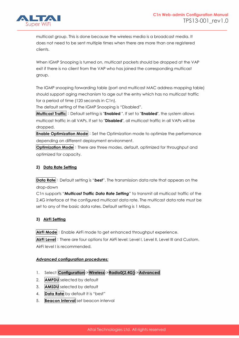
Multicast Traffic:Default setting is "Enabled ". If set to "Enabled", the system allows
multicast traffic in all VAPs. If set to "Disabled", all multicast traffic in all VAPs will be
dropped.
Enable Optimization Mode:Set the Optimization mode to optimize the performance
depending on different deployment environment.
Optimization Mode:There are three modes, default, optimized for throughput and
optimized for capacity.
2) Data Rate Setting
Data Rate:Default setting is “best”. The transmission data rate that appears on the
drop-down
C1n supports “Multicast Traffic Data Rate Setting” to transmit all multicast traffic of the
2.4G interface at the configured multicast data rate. The multicast data rate must be
set to any of the basic data rates. Default setting is 1 Mbps.
3) AirFi Setting
AirFi Mode:Enable AirFi mode to get enhanced throughput experience.
AirFi Level:There are four options for AirFi level: Level I, Level II, Level III and Custom.
AirFi level I is recommended.
Advanced configuration procedures:
1. Select Configuration ->Wireless ->Radio0(2.4G) ->Advanced
2. AMPDU selected by default
3. AMSDU selected by default
4. Data Rate by default it is “best”
5. Beacon Interval set beacon interval
Altai Technologies Ltd. All rights reserved
C1n Web-admin Configuration Manual
TPS13-001_rev1.0
6. Distance set target area distance
7. IGMP Snooping choose IGMP snooping mode if need
8. Multicast Traffic allow or block multicast traffic
9. Multicast Data Rate set multicast data rate
10. Click Submit
11. Click Save&Apply to apply
Warnings: The default setting for advance is recommended.
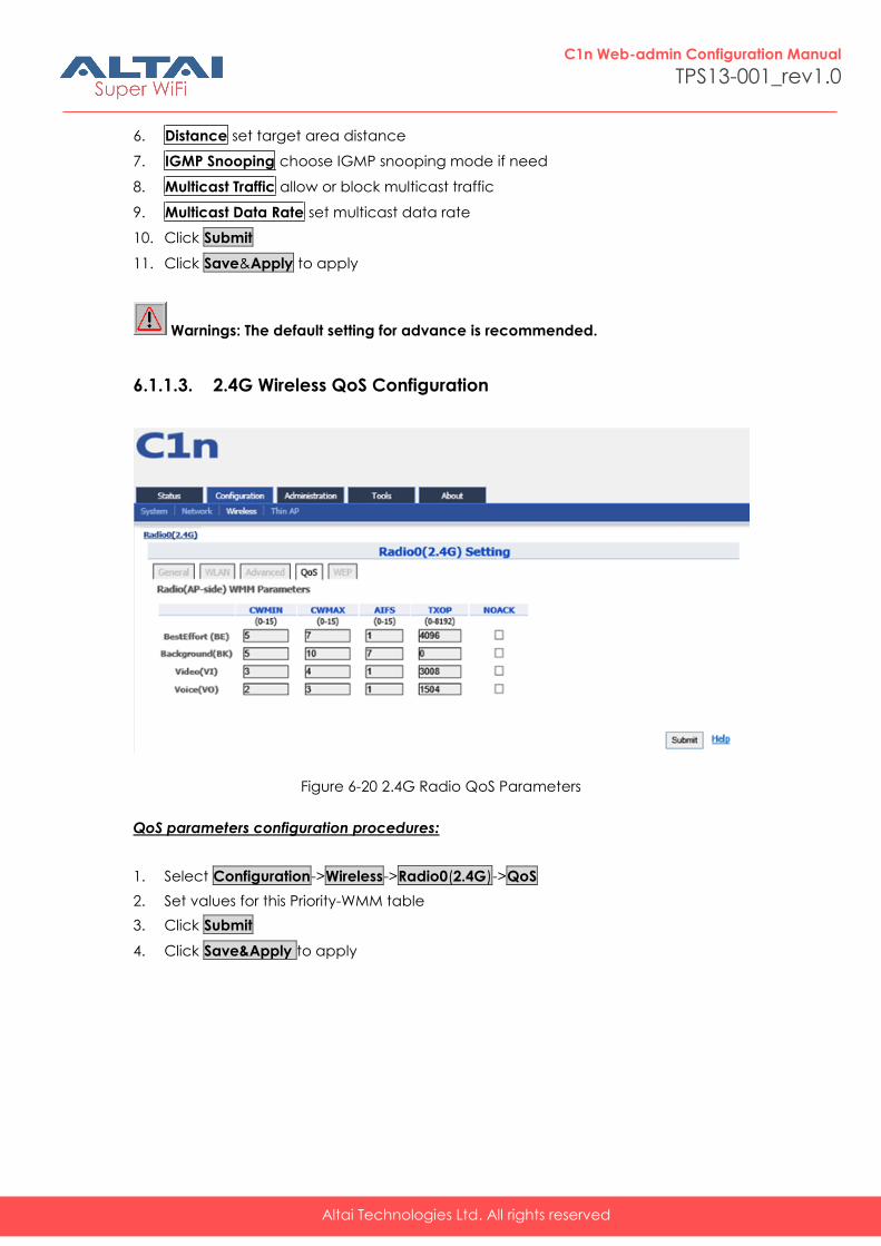
6.1.1.3. 2.4G Wireless QoS Configuration
Figure 6-20 2.4G Radio QoS Parameters
QoS parameters configuration procedures:
1. Select Configuration->Wireless->Radio0(2.4G)->QoS
2. Set values for this Priority-WMM table
3. Click Submit
4. Click Save&Apply to apply

Altai Technologies Ltd. All rights reserved
C1n Web-admin Configuration Manual
TPS13-001_rev1.0
6.1.1.4. 2.4G WEP Key
Figure 6-21 2.4G Radio WEP Key
Procedures:
1. Select Configuration->Wireless->Radio0(2.4G)->WEP
2. Key Entry Method select the key format
3. Input key phrase in related WEP Key
4. Click Submit
5. Click Save&Apply to apply
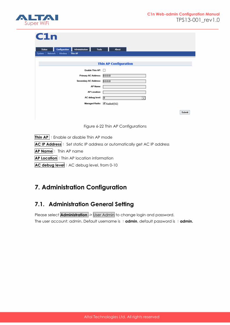
6.2. Thin AP Configuration
Altai Technologies Ltd. All rights reserved
C1n Web-admin Configuration Manual
TPS13-001_rev1.0
Figure 6-22 Thin AP Configurations
Thin AP :Enable or disable Thin AP mode
AC IP Address: Set static IP address or automatically get AC IP address
AP Name: Thin AP name
AP Location:Thin AP location information
AC debug level:AC debug level, from 0-10
7. Administration Configuration
7.1. Administration General Setting
Please select Administration -> User Admin to change login and password.
The user account: admin. Default username is :admin, default password is :admin.
Altai Technologies Ltd. All rights reserved
C1n Web-admin Configuration Manual
TPS13-001_rev1.0
Figure 7-1 User Admin
Procedures:
1. Select Administration -> User Admin,
2. Password set password
3. Confirm Password input password again to confirm
4. Click Submit
5. Click Save&Apply to apply
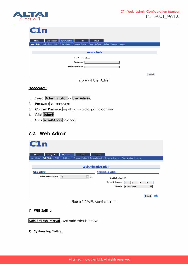
7.2. Web Admin
Figure 7-2 WEB Administration
1) WEB Setting
Auto Refresh Interval:Set auto refresh interval
2) System Log Setting
Altai Technologies Ltd. All rights reserved
C1n Web-admin Configuration Manual
TPS13-001_rev1.0
Enable Syslog:Enable or disable Syslog.
Server IP Address:Type in the IP address of syslog server.
Severity:There are eight kinds of severities: Emergency, Alert, Critical, Error, Warning,
Notice, Information and Debug.
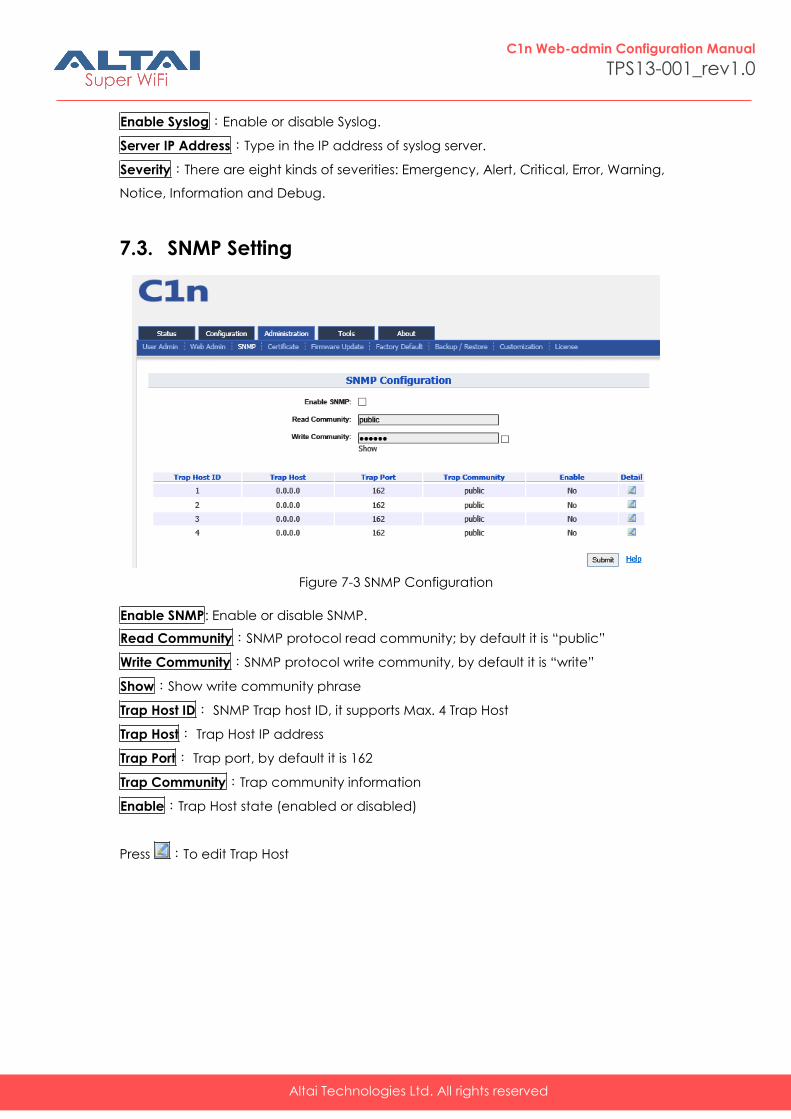
7.3. SNMP Setting
Figure 7-3 SNMP Configuration
Enable SNMP: Enable or disable SNMP.
Read Community:SNMP protocol read community; by default it is “public”
Write Community:SNMP protocol write community, by default it is “write”
Show:Show write community phrase
Trap Host ID: SNMP Trap host ID, it supports Max. 4 Trap Host
Trap Host: Trap Host IP address
Trap Port: Trap port, by default it is 162
Trap Community:Trap community information
Enable:Trap Host state (enabled or disabled)
Press :To edit Trap Host
Altai Technologies Ltd. All rights reserved
C1n Web-admin Configuration Manual
TPS13-001_rev1.0
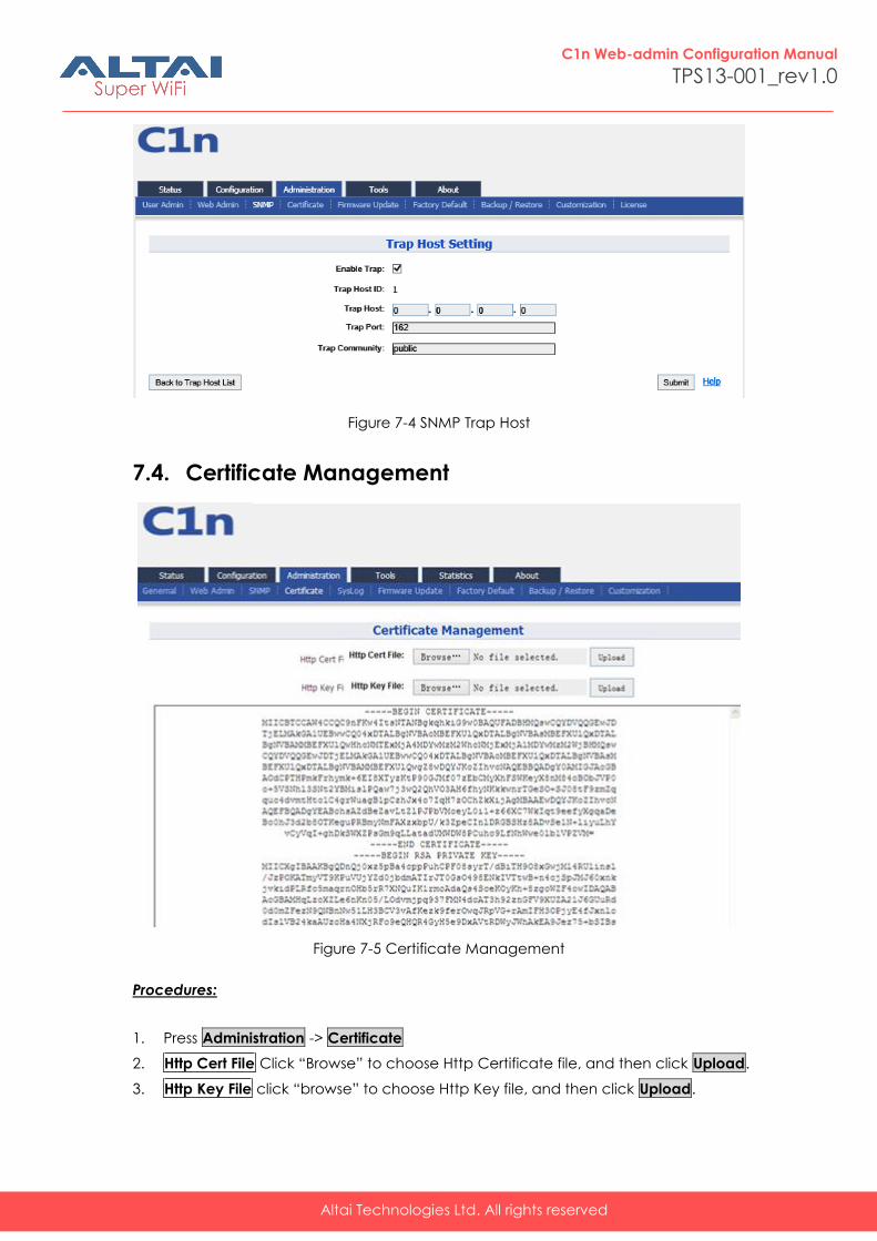
Figure 7-4 SNMP Trap Host
7.4. Certificate Management
Figure 7-5 Certificate Management
Procedures:
1. Press Administration -> Certificate
2. Http Cert File Click “Browse” to choose Http Certificate file, and then click Upload.
3. Http Key File click “browse” to choose Http Key file, and then click Upload.
Altai Technologies Ltd. All rights reserved
C1n Web-admin Configuration Manual
TPS13-001_rev1.0
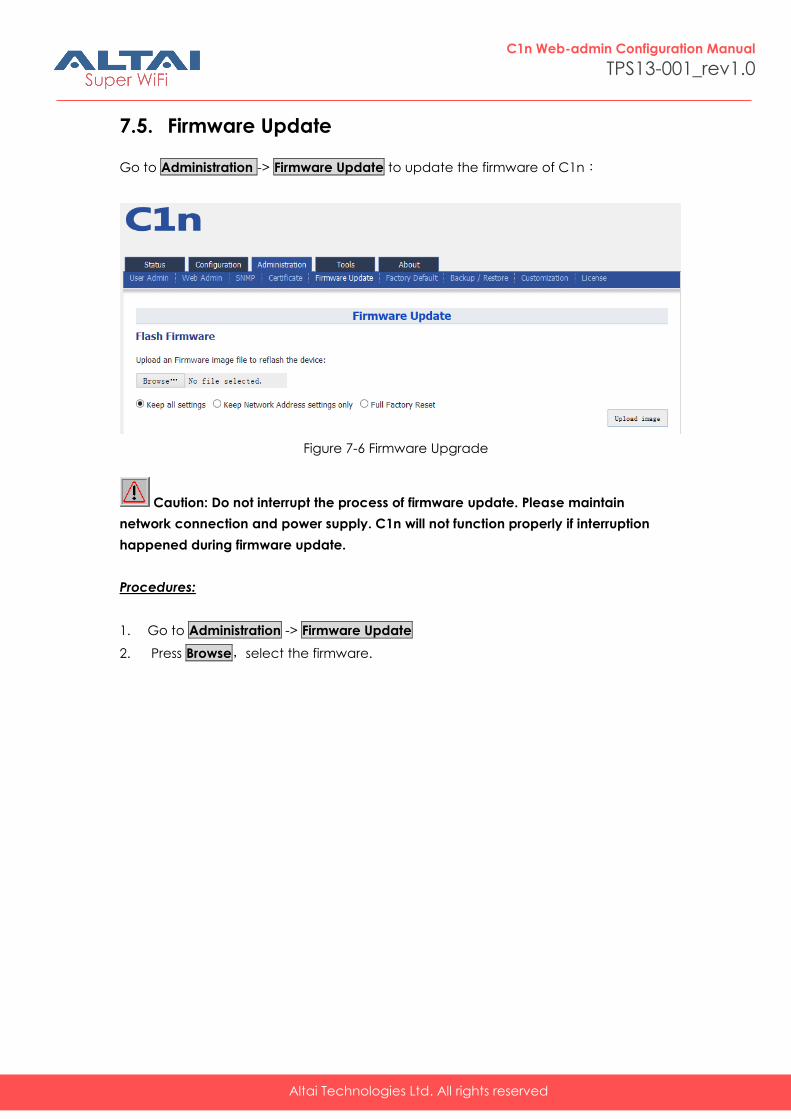
7.5. Firmware Update
Go to Administration -> Firmware Update to update the firmware of C1n:
Figure 7-6 Firmware Upgrade
Caution: Do not interrupt the process of firmware update. Please maintain
network connection and power supply. C1n will not function properly if interruption
happened during firmware update.
Procedures:
1. Go to Administration -> Firmware Update
2. Press Browse,select the firmware.
Altai Technologies Ltd. All rights reserved
C1n Web-admin Configuration Manual
TPS13-001_rev1.0
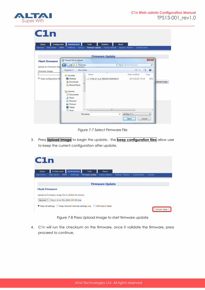
Figure 7-7 Select Firmware File
3. Press Upload image to begin the update,the keep configuration files allow user
to keep the current configuration after update.
Figure 7-8 Press Upload Image to start firmware update
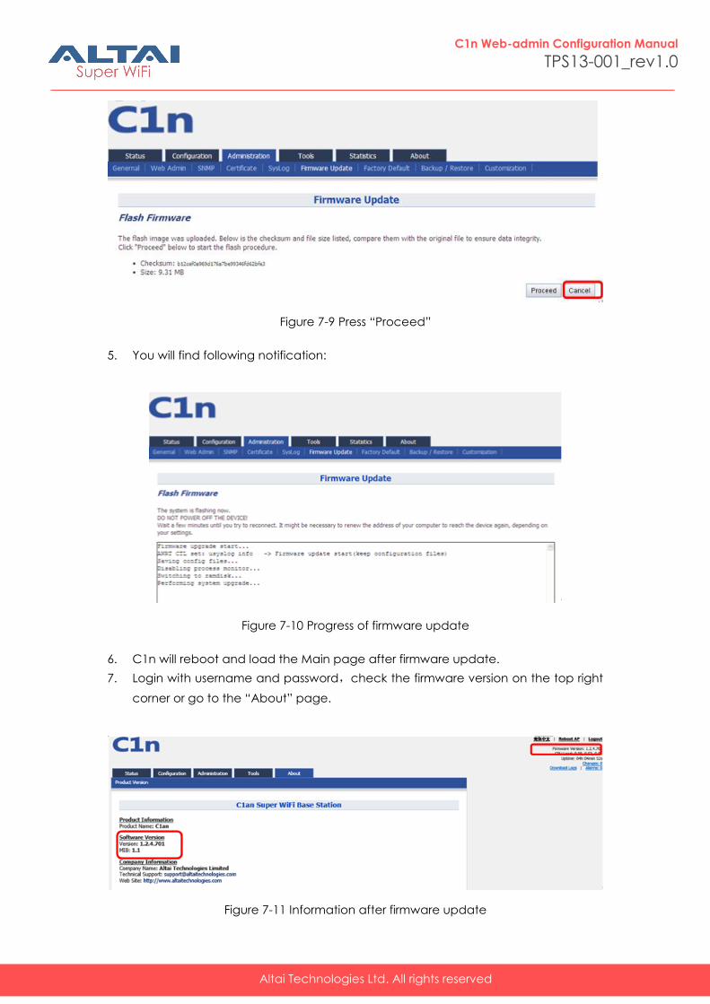
4. C1n will run the checksum on the firmware, once it validate the firmware, press
proceed to continue,
Altai Technologies Ltd. All rights reserved
C1n Web-admin Configuration Manual
TPS13-001_rev1.0
Figure 7-9 Press “Proceed”
5. You will find following notification:
Figure 7-10 Progress of firmware update
6. C1n will reboot and load the Main page after firmware update.
7. Login with username and password,check the firmware version on the top right
corner or go to the “About” page.
Figure 7-11 Information after firmware update
Altai Technologies Ltd. All rights reserved
C1n Web-admin Configuration Manual
TPS13-001_rev1.0
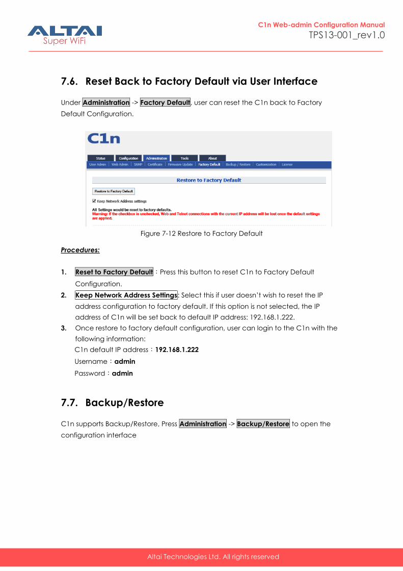
7.6. Reset Back to Factory Default via User Interface
Under Administration -> Factory Default, user can reset the C1n back to Factory
Default Configuration.
Figure 7-12 Restore to Factory Default
Procedures:
1. Reset to Factory Default:Press this button to reset C1n to Factory Default
Configuration.
2. Keep Network Address Settings: Select this if user doesn’t wish to reset the IP
address configuration to factory default. If this option is not selected, the IP
address of C1n will be set back to default IP address: 192.168.1.222.
3. Once restore to factory default configuration, user can login to the C1n with the
following information:
C1n default IP address:192.168.1.222
Username:admin
Password:admin
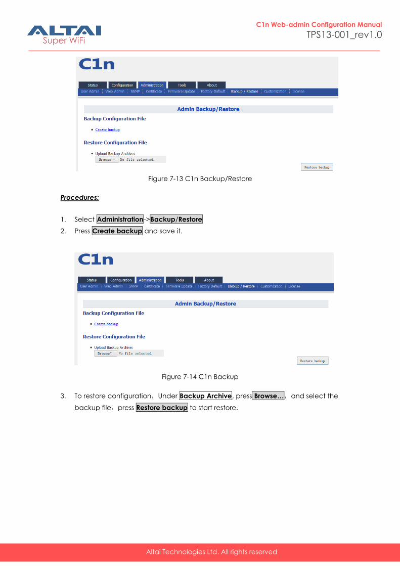
7.7. Backup/Restore
C1n supports Backup/Restore, Press Administration -> Backup/Restore to open the
configuration interface
Altai Technologies Ltd. All rights reserved
C1n Web-admin Configuration Manual
TPS13-001_rev1.0
Figure 7-13 C1n Backup/Restore
Procedures:
1. Select Administration->Backup/Restore
2. Press Create backup and save it.
Figure 7-14 C1n Backup
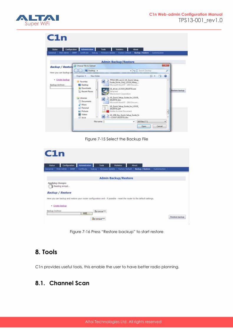
3. To restore configuration,Under Backup Archive, press Browse…,and select the
backup file,press Restore backup to start restore.
Altai Technologies Ltd. All rights reserved
C1n Web-admin Configuration Manual
TPS13-001_rev1.0
Figure 7-15 Select the Backup File
Figure 7-16 Press “Restore backup” to start restore
8. Tools
C1n provides useful tools, this enable the user to have better radio planning.
8.1. Channel Scan
Altai Technologies Ltd. All rights reserved
C1n Web-admin Configuration Manual
TPS13-001_rev1.0
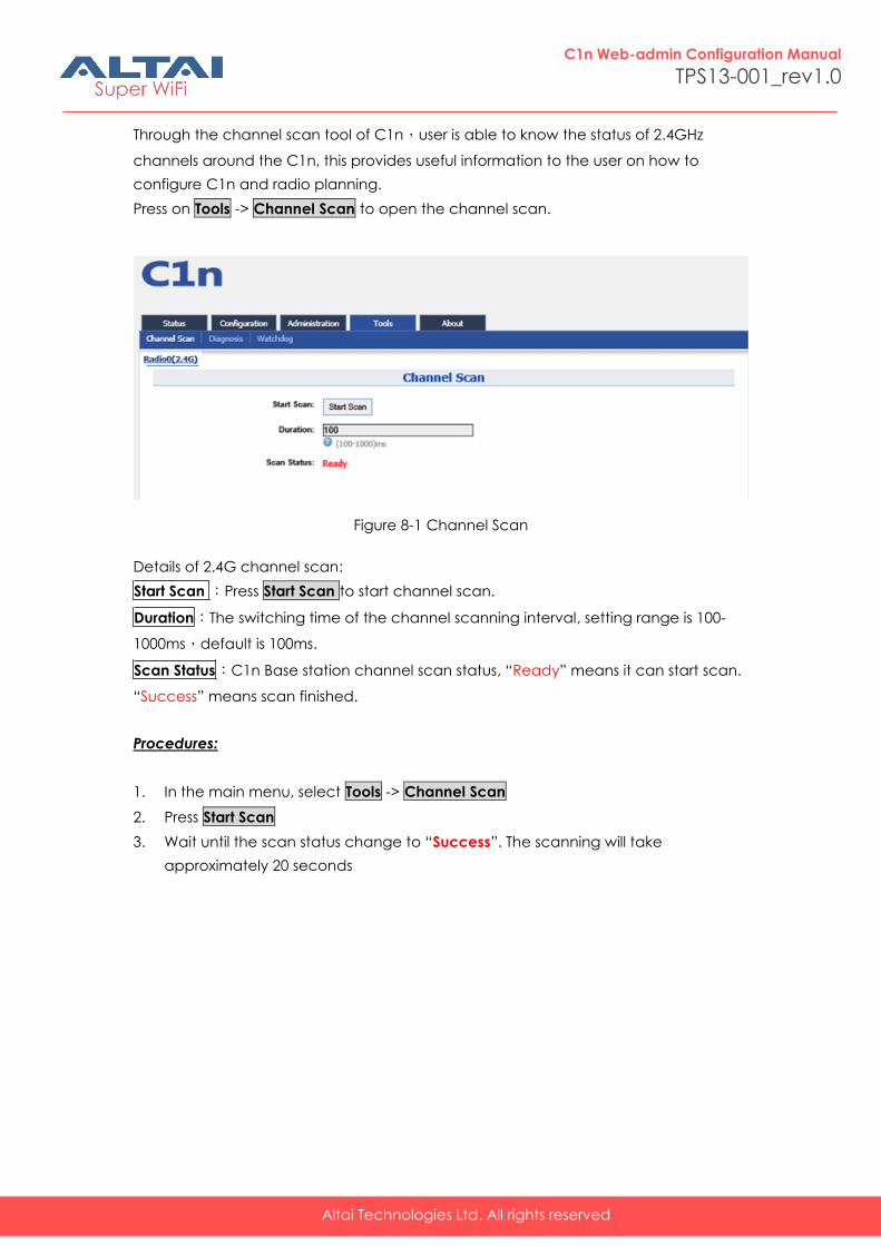
Through the channel scan tool of C1n,user is able to know the status of 2.4GHz
channels around the C1n, this provides useful information to the user on how to
configure C1n and radio planning.
Press on Tools -> Channel Scan to open the channel scan.
Figure 8-1 Channel Scan
Details of 2.4G channel scan:
Start Scan :Press Start Scan to start channel scan.
Duration:The switching time of the channel scanning interval, setting range is 100-
1000ms,default is 100ms.
Scan Status:C1n Base station channel scan status, “Ready” means it can start scan.
“Success” means scan finished.
Procedures:
1. In the main menu, select Tools -> Channel Scan
2. Press Start Scan
3. Wait until the scan status change to “Success”. The scanning will take
approximately 20 seconds
Altai Technologies Ltd. All rights reserved
C1n Web-admin Configuration Manual
TPS13-001_rev1.0
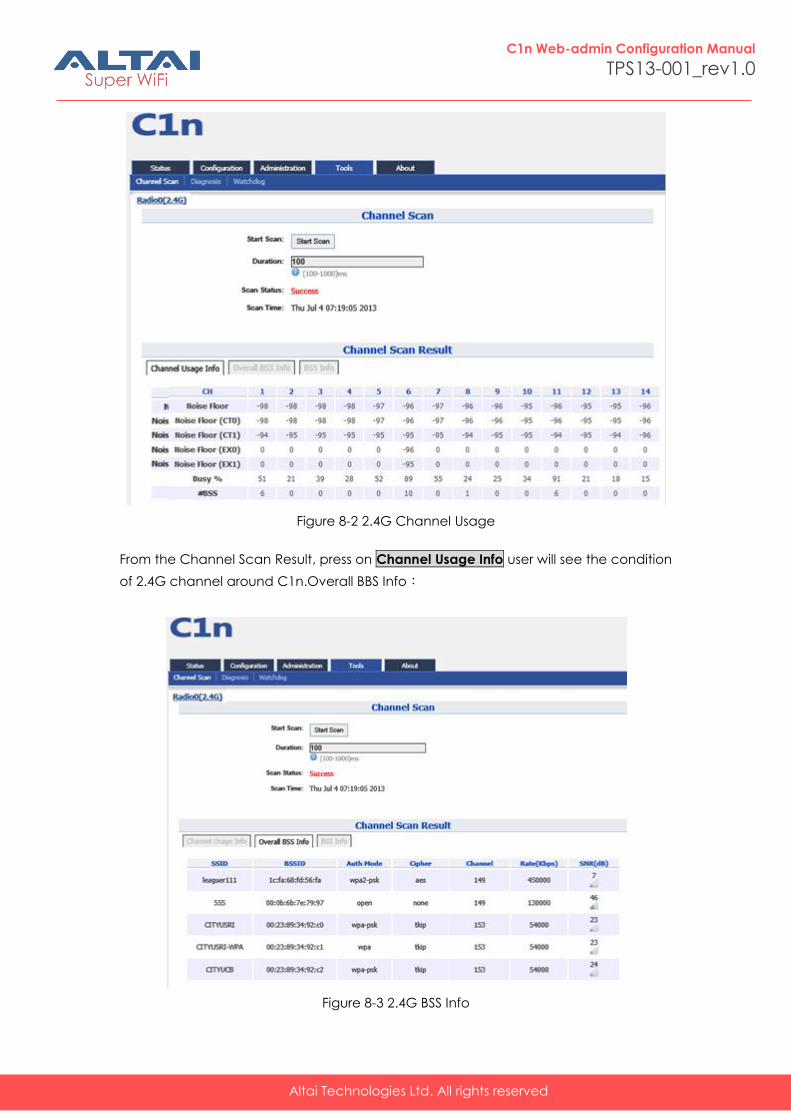
Figure 8-2 2.4G Channel Usage
From the Channel Scan Result, press on Channel Usage Info user will see the condition
of 2.4G channel around C1n.Overall BBS Info:
Figure 8-3 2.4G BSS Info
Altai Technologies Ltd. All rights reserved
C1n Web-admin Configuration Manual
TPS13-001_rev1.0
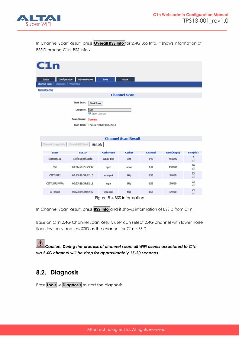
In Channel Scan Result, press Overall BSS Info for 2.4G BSS Info, it shows information of
BSSID around C1n. BSS Info:
Figure 8-4 BSS information
In Channel Scan Result, press BSS Info and it shows information of BSSID from C1n.
Base on C1n 2.4G Channel Scan Result, user can select 2.4G channel with lower noise
floor, less busy and less SSID as the channel for C1n’s SSID.
Caution: During the process of channel scan, all WiFi clients associated to C1n
via 2.4G channel will be drop for approximately 15-20 seconds.
8.2. Diagnosis
Press Tools -> Diagnosis to start the diagnosis.
Altai Technologies Ltd. All rights reserved
C1n Web-admin Configuration Manual
TPS13-001_rev1.0
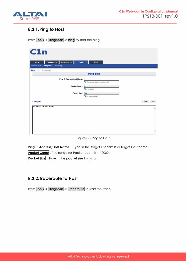
8.2.1. Ping to Host
Press Tools -> Diagnosis -> Ping to start the ping.
Figure 8-5 Ping to Host
Ping IP Address/Host Name :Type in the target IP address or target Host name.
Packet Count:The range for Packet count is 1-10000.
Packet Size:Type in the packet size for ping.
8.2.2. Traceroute to Host
Press Tools -> Diagnosis -> Traceroute to start the trace.
Altai Technologies Ltd. All rights reserved
C1n Web-admin Configuration Manual
TPS13-001_rev1.0
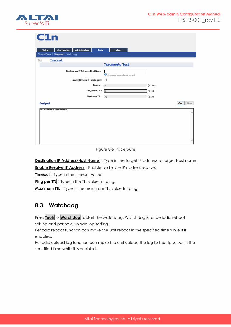
Figure 8-6 Traceroute
Destination IP Address/Host Name :Type in the target IP address or target Host name.
Enable Resolve IP Address:Enable or disable IP address resolve.
Timeout:Type in the timeout value.
Ping per TTL:Type in the TTL value for ping.
Maximum TTL:Type in the maximum TTL value for ping.
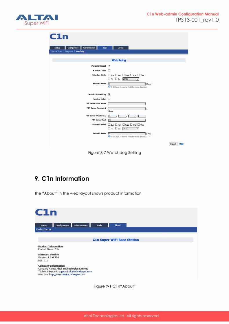
8.3. Watchdog
Press Tools -> Watchdog to start the watchdog. Watchdog is for periodic reboot
setting and periodic upload log setting.
Periodic reboot function can make the unit reboot in the specified time while it is
enabled.
Periodic upload log function can make the unit upload the log to the ftp server in the
specified time while it is enabled.
Altai Technologies Ltd. All rights reserved
C1n Web-admin Configuration Manual
TPS13-001_rev1.0
Figure 8-7 Watchdog Setting
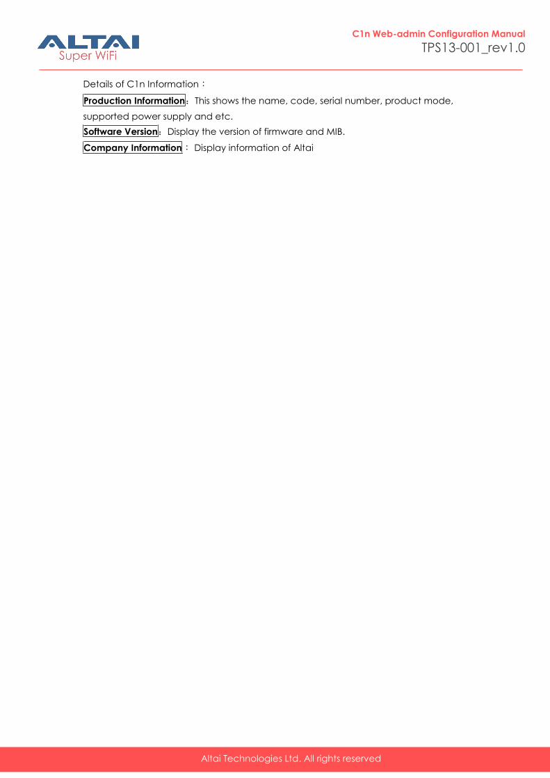
9. C1n Information
The “About” in the web layout shows product information
Figure 9-1 C1n“About”
Altai Technologies Ltd. All rights reserved
C1n Web-admin Configuration Manual
TPS13-001_rev1.0
Details of C1n Information:
Production Information:This shows the name, code, serial number, product mode,
supported power supply and etc.
Software Version:Display the version of firmware and MIB.
Company Information: Display information of Altai