Students will understand global water resources, use, and pollution, including:

We understand water.
Filters | GENO-fine filter FM
Operation manual

General Contact Germany
International Sales Phone +49 9074 41-145
Technical Service Phone +49 9074 41-333 Fax +49 9074 41-120
Availability Monday to Thursday 7:00 am - 6:00 pm
Friday 7:00 am - 4:00 pm
Copyright The manufacturer reserves the copyright to this operation manual. Without the written consent of Grünbeck Wasseraufbereitung GmbH, no part of this manual may be reproduced in any way, nor may any part be processed, duplicated or distributed using electronic systems. Non-compliance with the aforementioned stipulations shall be subject to compensation for damages.
We reserve the right to technical modifications. © by Grünbeck Wasseraufbereitung GmbH
Translation of the original operation manual Edition of the operation manual: August 2019 Order no.: TD3-AF001en_004

Table of contents
3 | 40
Table of contents
1 About this manual ..................................................... 4
1.1 Other applicable documents ...................................... 4 1.2 Target group .............................................................. 4 1.3 Storage of documents ................................................ 4 1.4 Symbols used ............................................................ 4 1.5 Typographical conventions ........................................ 5 1.6 Validity of the manual ................................................ 5 1.7 Type plate .................................................................. 6
2 Safety ......................................................................... 7
2.1 Safety measures ........................................................ 7 2.2 Technical safety instructions ...................................... 8 2.3 Regulations ................................................................ 8 2.4 Responsibilities of the specialist installer and/or
the specialist company .............................................. 8 2.5 Responsibilities of the owner/user ............................. 9 2.6 Product-specific safety instructions ........................... 9 2.7 Shipping and storage ................................................. 9
3 Product description ................................................ 10
3.1 Intended use ............................................................ 10 3.2 Foreseeable misuse ................................................ 10 3.3 Product components ................................................ 11 3.4 Functional description .............................................. 12 3.5 Accessories ............................................................. 12
4 Installation ............................................................... 13
4.2 Requirements regarding the installation site ............ 15 4.3 Checking the scope of supply .................................. 16 4.4 Installing the product ................................................ 17
5 Start-up .....................................................................19
5.1 Starting up the product .............................................19 5.2 Handing over the product to the owner/user ............20
6 Cleaning, inspection, maintenance ........................21
6.1 Cleaning ...................................................................21 6.2 Intervals ....................................................................21 6.3 Inspection .................................................................22 6.4 Maintenance .............................................................22 6.5 Consumables ............................................................27 6.6 Spare parts ...............................................................27 6.7 Wearing parts ...........................................................27
7 Troubleshooting .......................................................28
8 Disposal ....................................................................29
8.1 Packaging .................................................................29 8.2 Product .....................................................................29
9 Technical specifications .........................................30
9.1 Pressure loss curves ................................................31
10 Operation log ............................................................32
10.1 Start-up log ...............................................................32 10.2 Maintenance .............................................................33
Index ...................................................................................37

About this manual
4 | 40 BA
_T
D3
-AF
00
1e
n_
00
4_F
ein
filter-
FM
.do
cx
1 About this manual
1.1 Other applicable documents
The following documents shall be deemed as applicable documents for the
GENO-fine filters FM:
● The manuals of all accessories used.
1.2 Target group
This manual is intended for specialist installers and owners/users.
1.3 Storage of documents
Keep this manual and all other applicable documents, so that they are available when
needed. Make sure that your specialist installer enters the proper start-up and annual
maintenance in chapter 10 of the operation log.
1.4 Symbols used
This symbol identifies instructions that you must comply with for your own personal safety
as well as to avoid damage to property.
This symbol identifies instructions that you must comply with in order to avoid damage to
property.
This symbol identifies important information about the product or its handling.
This symbol identifies work that may only be carried out by a specialist installer. In
Germany, the installation company must be registered in an installation directory of a water
supply company acc. to §12(2) AVB Wasser V (German Ordinance on General Conditions
for the Supply of Water).
This symbol identifies work that may only be performed by Grünbeck's technical
service/authorised service company or by specialist installers trained by Grünbeck.
About this manual
5 | 40
BA
_T
D3
-AF
00
1e
n_
00
4_F
ein
filter-
FM
.do
cx
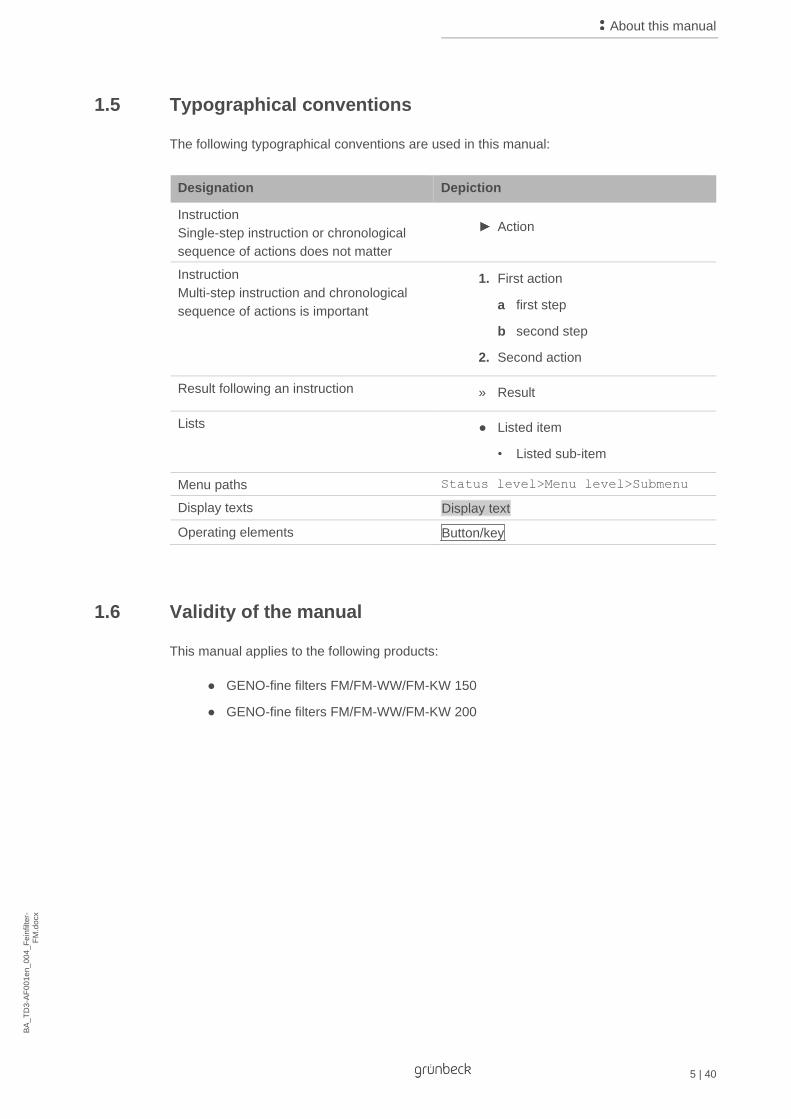
1.5 Typographical conventions
The following typographical conventions are used in this manual:
Designation Depiction
Instruction
Single-step instruction or chronological
sequence of actions does not matter
Action
Instruction
Multi-step instruction and chronological
sequence of actions is important
1. First action
a first step
b second step
2. Second action
Result following an instruction » Result
Lists ● Listed item
• Listed sub-item
Menu paths Status level>Menu level>Submenu
Display texts Display text
Operating elements Button/key
1.6 Validity of the manual
This manual applies to the following products:
● GENO-fine filters FM/FM-WW/FM-KW 150
● GENO-fine filters FM/FM-WW/FM-KW 200

About this manual
6 | 40 BA
_T
D3
-AF
00
1e
n_
00
4_F
ein
filter-
FM
.do
cx
1.7 Type plate
The type plate is located on the side of the inlet pipe (raw water inlet).
Please specify the data shown on the type plate in order to speed up the processing of your
inquiries or orders.
► Enter the necessary information in the table below to have it readily available
whenever necessary.
Item Designation Item Designation
1 EAC mark 2 Product designation
3 Nominal connection diameter 4 Max. water temperature
5 Nominal flow 6 Approved filter elements
7 Pore size 8 Order no.
9 Nominal pressure 10 Serial no.
● Product designation: GENO-fine filter ________________
● Order no.: 102_____________
● Serial no.: ________________

Safety
7 | 40
BA
_T
D3
-AF
00
1e
n_
00
4_F
ein
filter-
FM
.do
cx
2 Safety
WARNING: Contamination of drinking water due to improper handling.
● Risk of infectious diseases.
► Have the installation, start-up and annual maintenance carried out by specialist
installers only.
2.1 Safety measures
● Carefully read this manual before operating your product.
● Only operate the product if all components are installed properly.
● Only have persons working on your product that have read and understood the
present manual and that are qualified to do such work due to their vocational
training.
● Comply with the hygiene instructions in chapter 6. Failure to comply can result in
microbiological contamination of your drinking water installation.
● Keep your product permanently connected to the water supply.
● Safety equipment must never be removed, bridged or otherwise tampered with.
● Observe the maintenance intervals (refer to chapter 6.2). Failure to comply can
result in microbiological contamination of your drinking water installation.
● Children are not allowed to play with the product.
● This product can be used by children over 8 years of age and persons with limited
abilities or lack of experience if they are supervised or instructed in the safe use of
the product and understand the resulting hazards.
● Cleaning and maintenance must not be carried out by children.
Safety
8 | 40 BA
_T
D3
-AF
00
1e
n_
00
4_F
ein
filter-
FM
.do
cx
2.2 Technical safety instructions
This manual contains instructions that you must comply with for your own personal safety as
well as to avoid damage to property. The instructions are highlighted by a warning triangle
and have the following structure:
CAUTION: Type and source of danger.
● Possible consequences
► Preventive measures
The following signal words were defined subject to the degree of danger and may be used in
the present document:
● DANGER means that death or serious injury will result.
● WARNING means that death or serious injury may result.
● CAUTION means that minor bodily injuries may occur.
● NOTE (without warning triangle) means that damage to property may occur.
2.3 Regulations
When installing and starting up the system, amongst others, comply with the following
regulations and guidelines:
● Statutory regulations on environmental protection
● Provisions of the employers' liability insurance companies
● DIN EN 806 Specifications for installations inside buildings conveying water for
human consumption
● VDI 6023 Part 5 - 7 Specifications for installations inside buildings conveying water
for human consumption
2.4 Responsibilities of the specialist installer and/or the specialist company
Comply with the following instructions to ensure the proper and safe functioning of the
product:
● Only perform activities described in this manual.
● Perform all activities in accordance with all applicable standards and regulations.
● Brief the owner/user on the function and operation of the product.
● Advise the owner/user of the maintenance of the product.

Safety
9 | 40
BA
_T
D3
-AF
00
1e
n_
00
4_F
ein
filter-
FM
.do
cx
● Inform the owner/user about possible dangers that can arise during the operation
of the product.
● Fill in the operation log (refer to chapter 10).
2.5 Responsibilities of the owner/user
Comply with the following instructions to ensure the proper and safe functioning of the
product:
● Arrange for a specialist installer to carry out installation, start-up and maintenance.
● Have the product explained to you by the specialist installer.
● Only perform activities described in this manual.
● Do not carry out any activities that are explicitly designated for a specialist installer.
● Only use this product as intended.
● Make sure that the required inspection and maintenance work is carried out.
● Keep this manual.
2.6 Product-specific safety instructions
WARNING: If the intervals for inspection and replacement are not observed, the filter
element will become excessively polluted.
● Health risk due to contamination of the drinking water.
► Observe the intervals and recommendations for inspection and replacement of
the filter elements.
2.7 Shipping and storage
Transport
► Only transport the filters in their original packaging.
Storage
► Protect the product from:
● Damp, moisture, environmental impacts such as wind, rain, snow, etc.
● Frost, direct sunlight, severe heat exposure
● Chemicals, dyes, solvents and their vapours

Product description
10 | 40 BA
_T
D3
-AF
00
1e
n_
00
4_F
ein
filter-
FM
.do
cx
3 Product description
3.1 Intended use
● The GENO-fine filters FM are designed for the filtration of drinking and well water.
● The FM-WW filters are suitable for the filtration of process and boiler feed water - in
partial flow only - and as warm water filters for water temperatures up to 90 ºC.
● The FM-KW filters are suitable for the filtration of cooling and air conditioning water
– in partial flow only - and for water temperatures up to 90 °C.
● The filters can be used for positive and negative pressure applications.
● The filters are designed according to the stipulations of DIN EN 13443-1 and
DIN 19628 and are intended for installation into drinking water pipes according to
DIN EN 806-2.
● The filters protect the water pipes and connected water-carrying system parts from
malfunctions and corrosion damage due to undissolved impurities (particles), such
as rust particles, sand, etc.
3.2 Foreseeable misuse
● The filters are not suitable for circulation water that has been treated with
chemicals.
● The filters are neither suitable for oils, greases, solvents, soaps and other
lubricating media, nor for the separation of water-soluble substances.
● The filters must not be installed in vertical water pipes.

Product description
11 | 40
BA
_T
D3
-AF
00
1e
n_
00
4_F
ein
filter-
FM
.do
cx
3.3 Product components
Item Designation Item Designation
1 Deaerator 2 Cover
3 Cover ring 4 O-ring
5 Screws 6 Filter housing
7 Pressure gauge for inlet pressure 8 Flange
9 Draining valve 10 Pressure gauge for outlet pressure
11 Cap nut 12 Filter element
13 Support mesh 14 Retaining plate

Product description
12 | 40 BA
_T
D3
-AF
00
1e
n_
00
4_F
ein
filter-
FM
.do
cx
3.4 Functional description
The unfiltered drinking water flows into the filter from the inlet side and then passes through
the filter elements to the pure water outlet.
In the course of this process, foreign particles > 80 µm in size (standard) for FM 150,
> 50 µm (standard) for FM 200 and > 500 µm for FM-KW are retained.
Depending on their size and weight, the foreign particles either stick to the filter element or
fall straight down where they accumulate at the lowest point of the filter.
Due to the growing load of the filter elements, the differential pressure between the raw
water inlet and the pure water outlet increases.
If the differential pressure of 0.8 bar at the flow rate of the filter is exceeded, the filter
elements must be replaced.
3.5 Accessories
You can retrofit your product with additional accessories. Please contact your local
Grünbeck representative or Grünbeck’s headquarters in Hoechstaedt for more details
(refer to www.gruenbeck.com).
Designation Order no. Order no.
DN 150 DN 200
5 µm filter element 103 083
100 µm filter element 103 110 103 150
Quantity 2 14
Illustration Product Order no.
Differential pressure switch With electric contactor, continuously adjustable for visual or acoustic remote signal.
102 870
Hose extension kit for differential pressure switch 102 850
Parallel piping of two GENO-fine filters Subject to project

Installation
13 | 40
BA
_T
D3
-AF
00
1e
n_
00
4_F
ein
filter-
FM
.do
cx
4 Installation
The installation of a filter represents a major intervention into the drinking water system and
may only be performed by a specialist installer.
Installation in the drinking water system
In accordance with DIN EN 806-2 and DIN EN 1717, the product is installed in the water pipe
downstream of the water meter and upstream of distribution pipes or the systems to be
protected.
Item Designation Item Designation
1 Inlet shut-off valve 2 Outlet shut-off valve
Install shut-off valves upstream and downstream of the filter.
Installation
14 | 40 BA
_T
D3
-AF
00
1e
n_
00
4_F
ein
filter-
FM
.do
cx
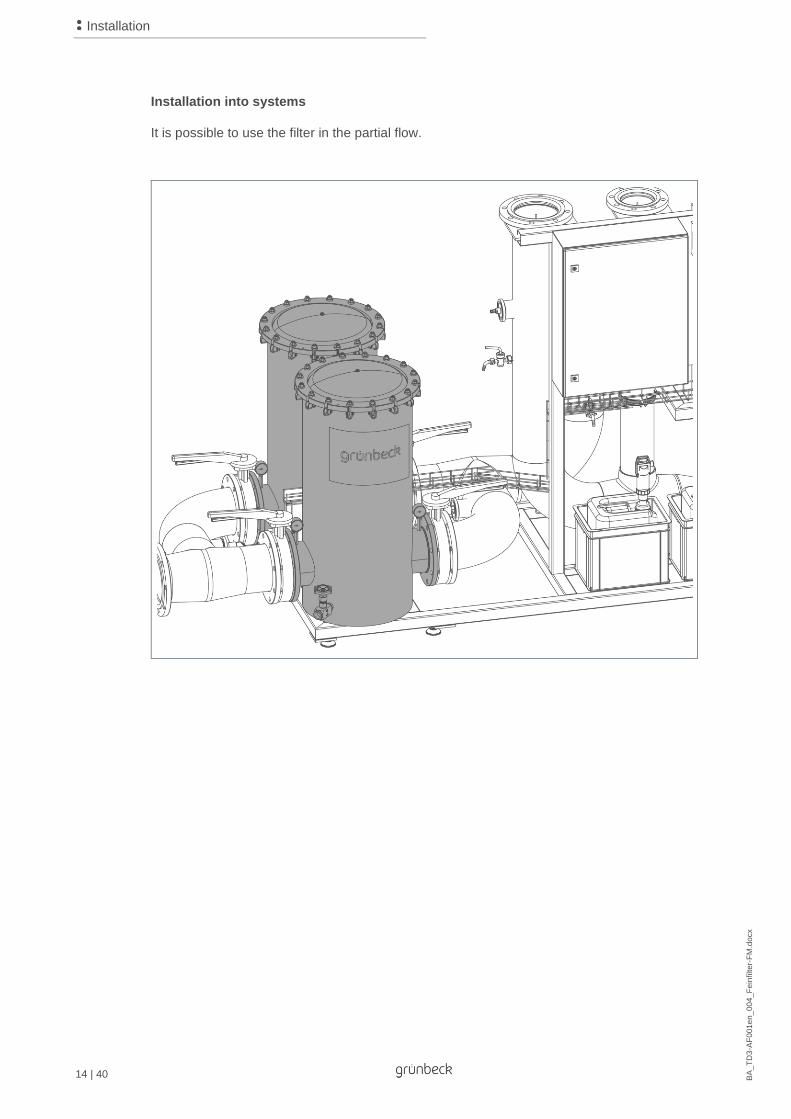
Installation into systems
It is possible to use the filter in the partial flow.

Installation
15 | 40
BA
_T
D3
-AF
00
1e
n_
00
4_F
ein
filter-
FM
.do
cx
Parallel piping
Parallel piping of 2 GENO-fine filters for the filtration of process, boiler feed, cooling and air
conditioning water in order to ensure an uninterrupted operation even during the
replacement of filter elements.
Item Designation Item Designation
1 Inlet shut-off valve 2 Outlet shut-off valve
4.2 Requirements regarding the installation site
Observe local installation directives, general guidelines and technical specifications.
● The installation site must be frost-proof and ensure the filter's protection from
chemicals, dyes, solvents, vapours and direct sunlight.
● The installation room must provide an adequately dimensioned floor drain. If no
floor drain is available, an appropriate safety device must be installed in order to
prevent water damage. We recommend using a protectliQ:A.
● The installation site must be easily accessible for maintenance purposes.

Installation
16 | 40 BA
_T
D3
-AF
00
1e
n_
00
4_F
ein
filter-
FM
.do
cx
4.3 Checking the scope of supply
Item Designation Item Designation
1 Deaerator 2 GENO-fine filter with flange connection according to DIN EN 1092-1
3 Operation manual 4 Draining valve
5 Pressure gauge (2 pieces) 6 Filter elements
► Check the scope of supply for completeness and damage.

Installation
17 | 40
BA
_T
D3
-AF
00
1e
n_
00
4_F
ein
filter-
FM
.do
cx
4.4 Installing the product
The filter comes with loose parts. These individual parts must be installed on site by the
client according to the area of application.
► Check the flow direction prior to assembling the individual parts.
► Install the individual parts in accordance with the direction of flow.
NOTE: Seal loose parts during assembly.
● Leakage at the filter.
► Seal the pressure gauge components on site with e.g. hemp; Teflon tape.
Only install the GENO-fine filter FM horizontally and without mechanical stress.
4.4.1 Installing the pressure gauges
1. Screw the pressure gauges to the flanges at the top of the support pipe.

Installation
18 | 40 BA
_T
D3
-AF
00
1e
n_
00
4_F
ein
filter-
FM
.do
cx
4.4.2 Installation of the filter in the pipe
1. Prepare the pipe with flange connection according to DIN EN 1092-1
(the distance between the two seals must be 690 mm).
2. Check the flow direction given on site.
3. By way of the screw connections, screw the filter to the flanges without any
mechanical stress.

Start-up
19 | 40
BA
_T
D3
-AF
00
1e
n_
00
4_F
ein
filter-
FM
.do
cx
5 Start-up
5.1 Starting up the product
► Carry out the following steps after installation and any maintenance.
In order to drain the filter, a hose fitting with male thread must be mounted at the draining
valve by the client on site (female thread of draining valve 1 inch).
► Make sure that the draining valve is closed.
1. Open the deaerator.
2. Slowly open shut-off valve 1 (inlet).
3. Close the deaerator when no more air is escaping.
» The filter is vented.
4. Slowly open shut-off valve 2 (outlet).
5. Check the filter for tightness.
» The filter is in operation.
Start-up
20 | 40 BA
_T
D3
-AF
00
1e
n_
00
4_F
ein
filter-
FM
.do
cx
5.2 Handing over the product to the owner/user
► Explain to the owner/user how the product works.
► Use the manual to brief the owner/user and answer any questions.
► Inform the owner/user about the need for inspections and maintenance.
► Hand over all documents to the owner/user for keeping.
► Enter the initial start-up in the operation log (refer to chapter 10.1).

Cleaning, inspection, maintenance
21 | 40
BA
_T
D3
-AF
00
1e
n_
00
4_F
ein
filter-
FM
.do
cx
6 Cleaning, inspection, maintenance
WARNING: Danger of contaminated drinking water if the work is not carried out properly.
● Risk of infectious diseases.
► Pay attention to hygiene when working on the product.
Inspection and maintenance of a filter is prescribed in the DIN EN 806-5 standard. Regular
maintenance ensures trouble-free and hygienic operation.
By concluding a maintenance contract, you ensure that all maintenance work is carried out
on time.
► Only use genuine spare and wearing parts from Grünbeck.
6.1 Cleaning
► Only clean the outside of the product.
► Do not use any strong or abrasive cleaning agents.
► Wipe the housing with a damp cloth.
NOTE: Do not clean the filter with cleaning agents that contain alcohol or solvents.
● These substances will damage components.
► Use a mild/pH-neutral soap solution.
6.2 Intervals
Task Interval Execution
Inspection 2 months Visual/functional check, reading off the pressure
Maintenance 6 months Replacing the filter elements
Annually Checking the O-ring for wear and tear,
checking for tight fit
Maintenance 2 years Recommended: replacing the O-ring

Cleaning, inspection, maintenance
22 | 40 BA
_T
D3
-AF
00
1e
n_
00
4_F
ein
filter-
FM
.do
cx
6.3 Inspection
According to DIN EN 806-5, the owner/user must inspect the filters every 2 months.
To conduct an inspection, proceed as follows:
1. Check the installation for leaks.
2. Open several water withdrawal points (generate max. flow).
3. Read off the inlet and outlet pressure at the pressure gauges.
4. Calculate the differential pressure: inlet pressure (upper pressure gauge) outlet
pressure (lower pressure gauge) = differential pressure (max. 0.8 bar).
5. Replace the filter elements if the differential pressure is > 0.8 bar.
6. If the differential pressure of the device cannot be reduced by replacing the filter
elements, there is a malfunction.
6.4 Maintenance
WARNING: If the intervals for inspection and replacement are not observed, the filter
elements will become excessively polluted.
● Health risk due to contamination of the drinking water.
► Observe the intervals for inspection and replacement of the filter elements.
Some regular work is necessary in order to ensure the proper functioning of the product in
the long term. For this purpose, DIN EN 806-5 recommends a semi-annual and an annual
maintenance.
The filter elements must be replaced every 6 months for hygiene reasons, in line with DIN
EN 806-5. We recommend replacing the O-ring of the cover every 2 years.

Cleaning, inspection, maintenance
23 | 40
BA
_T
D3
-AF
00
1e
n_
00
4_F
ein
filter-
FM
.do
cx
6.4.1 Semi-annual maintenance
Preparations for the replacement of the filter elements
1. Install a hose fitting with male thread at the draining valve on site.
2. Direct a waste water pipe towards the sewer.
3. Close shut-off valves 1 inlet and 2 outlet.
4. Open the deaerator.
5. Open the handle of the draining valve and allow the water to drain completely.
» The filter is drained.

Cleaning, inspection, maintenance
24 | 40 BA
_T
D3
-AF
00
1e
n_
00
4_F
ein
filter-
FM
.do
cx
1. Loosen the nuts.
2. Remove the washers.
3. Remove the cover ring.
4. Remove the cover.
5. Flush the sunk dirt particles from the filter housing via the draining valve.
» The filter is open and flushed.

Cleaning, inspection, maintenance
25 | 40
BA
_T
D3
-AF
00
1e
n_
00
4_F
ein
filter-
FM
.do
cx
Hygienic replacement of the filter element
1. Unscrew the cap nut.
2. Remove the dirty filter element from the support mesh.
3. Dispose of the used filter element in accordance with local regulations.
For hygienic reasons, the new filter element must not be touched with bare hands.
4. Slide the new filter element in its foil packaging over the support mesh.
5. Pull off the foil without touching the filter element.
6. Repeat the process for all filter elements.
7. Screw the cap nuts on again.
8. Check the sealing surfaces and the O-ring for cleanliness.

Cleaning, inspection, maintenance
26 | 40 BA
_T
D3
-AF
00
1e
n_
00
4_F
ein
filter-
FM
.do
cx
9. Put on the filter cover.
10. Put on the cover ring.
11. Evenly and gradually screw on the nuts with washers crosswise.
» The cover is fully tightened.
12. Put the filter into operation – refer to chapter 5.
» The filter is ready to use.
Cleaning, inspection, maintenance
27 | 40
BA
_T
D3
-AF
00
1e
n_
00
4_F
ein
filter-
FM
.do
cx
6.4.2 Annual maintenance
Carrying out annual maintenance work requires specialist knowledge. This kind of
maintenance work may only be carried out by Grünbeck's technical service/authorised
service company or by specialist installers trained by Grünbeck.
In addition to the semi-annual maintenance, the following work needs to be done:
1. Check the O-ring for wear and tear.
2. Check the filter for tight fit and leaks.
6.5 Consumables
Designation Order no.:
FM 150 filter element 80 μm (2 pieces) 103 077
FM 200 filter element 50 μm (28 pieces) 103 153
Number of filter elements subject to size of filter.
6.6 Spare parts
For spare parts and consumables please contact your local Grünbeck representation which
you may find on the Internet at www.gruenbeck.com.
6.7 Wearing parts
Although these parts are wearing parts, we grant a limited warranty period of 6 months.
Wearing parts are listed below.
Designation Order no.:
O-ring 102 166

Troubleshooting
28 | 40 BA
_T
D3
-AF
00
1e
n_
00
4_F
ein
filter-
FM
.do
cx
7 Troubleshooting
WARNING: Danger of contaminated drinking water due to stagnation.
● Risk of infectious diseases.
► Have malfunctions remedied immediately.
► If you cannot remedy malfunctions with the instructions given below, contact
Grünbeck's technical service/authorised service company.
► Have your system data (refer to chapter 1.7) handy.
Troubleshooting may only be carried out by a specialist installer.
Malfunction
Explanation/Cause of
error Troubleshooting
The differential pressure
exceeds 0.8 bar at flow
capacity.
The filter elements are dirty. Replace the filter elements.
The shut-off valves are not
open completely.
Completely open the shut-
off valves.
Water escapes at the screw
connections of the filter
housing.
The screw connections are
leaky.
Have the screw connections
at the filter housing replaced
by a specialist installer.
Water escapes at the cover. The nuts have not been
tightened enough.
Tighten the nuts.
The O-ring has not been
inserted correctly into the
groove.
Completely/properly insert
the O-ring into the groove.
Solids in the filtered water. Inappropriately high flow
through the filter.
Check the support mesh
and the filter elements for
damage or leaks.
Filter element/support mesh
damaged or not installed
properly.
Check the installation of the
filter elements / the filter
mesh and if necessary,
replace them with new filter
elements / support mesh /
seals

Disposal
29 | 40
BA
_T
D3
-AF
00
1e
n_
00
4_F
ein
filter-
FM
.do
cx
8 Disposal
Comply with the applicable national regulations.
8.1 Packaging
Dispose of the packaging in an environmentally sound manner.
8.2 Product
If this symbol (crossed out waste bin) is on the product, this product is subject to the
European Directive 2012/19/EU. This means that this product and the electrical and
electronic components must not be disposed of as household waste.
Find out about the local regulations on the separate collection of electrical and
electronic products.
Make use of the collection points available to you for the disposal of your product.
For information on collection points for your product, contact your municipality, the public
waste management authority, an authorised body for the disposal of electrical and
electronic products or your waste disposal service.

Technical specifications
30 | 40 BA
_T
D3
-AF
00
1e
n_
00
4_F
ein
filter-
FM
.do
cx
9 Technical specifications
Dimensions and weights GENO-fine filters FM/FM-WW/FM-KW
Nominal connection diameter DN 150 DN 200
A Total height [mm] 830 1190
B Overall height above centre of connection [mm] 597 956
C Overall height lower edge of filter to centre of connection [mm] 233 234
D Installation length without counter-flanges
acc. to DIN EN 1092-1 [mm] 690 690
E Min. distance from wall to centre of connection [mm] 300 300
F Clearance required for replacement of filter element [mm] 600 900
Filter elements, quantity piece(s) 14 28
Operating weight, approx. [kg] 255 327
Empty weight [kg] 100 124
General data
Max. water temperature FM [°C] 30
Max. water temperature FM-WW/FM-KW [°C] 90
Max. ambient temperature [°C] 5 – 40
Order no. (cold water version) 102 400 102 500
Order no. (warm water version) 102 401 102 501
Order no. (cooling water version) 102 470 102 570
Performance data
Flow rate at Δp 0.2 bar [m3/h] 150 280
Pore size cold water/warm water [µm] 80/500 50/500
Nominal pressure cold water/warm water PN 10/PN 6
Max. admissible differential pressure [bar] 0.8

Technical specifications
31 | 40
BA
_T
D3
-AF
00
1e
n_
00
4_F
ein
filter-
FM
.do
cx
9.1 Pressure loss curves
Item Designation Item Designation
1 Pressure difference [bar] 2 Flow rate [m3/h]

Operation log
32 | 40 BA
_T
D3
-AF
00
1e
n_
00
4_F
ein
filter-
FM
.do
cx
10 Operation log
Filters | GENO-fine filter__________________
Serial no.: _____________________________
10.1 Start-up log
Customer
Name:
Address:
Installation/Accessories
Floor drain available yes no
Safety device yes no
Operating values
Water pressure at raw water inlet [bar]
Water pressure downstream of pressure
reducer
[bar]
Remarks
Start-up
Company:
Service technician:
Work time certificate (no.):
Date/signature:

Operation log
33 | 40
BA
_T
D3
-AF
00
1e
n_
00
4_F
ein
filter-
FM
.do
cx
10.2 Maintenance
Date Work performed Signature
Operation log
34 | 40 BA
_T
D3
-AF
00
1e
n_
00
4_F
ein
filter-
FM
.do
cx
Date Work performed Signature
Operation log
35 | 40
BA
_T
D3
-AF
00
1e
n_
00
4_F
ein
filter-
FM
.do
cx
Date Work performed Signature

Operation log
36 | 40 BA
_T
D3
-AF
00
1e
n_
00
4_F
ein
filter-
FM
.do
cx
Date Work performed Signature
Notes
37 | 40
Notes
Index
38 | 40
Index
A
Accessories ....................................................................... 12
C
Consumables .................................................................... 27
H
Hygienic replacement of the filter element ......................... 25
I
Inspection .......................................................................... 22
Installation of the filter in the pipe. ..................................... 18
Installing the product ......................................................... 17
M
Maintenance ..................................................................... 22
P
Pressure loss curves ......................................................... 31
S
Spare parts ....................................................................... 27
Start-up ............................................................................. 19
T
Technical specifications .................................................... 30
Type plate ........................................................................... 6


Grünbeck Wasseraufbereitung GmbH Josef-Grünbeck-Str. 1 89420 Hoechstaedt/Germany
For more information go to www.gruenbeck.com
+49 9074 41-0
+49 9074 41-100
[email protected] www.gruenbeck.com