WCDMA Performance - Radio Access Network KPI Definition Manual for UMTS6.1(V1.0)
For internal use only1 © Nokia Siemens Networks
WCDMA : KPI ANALYSIS & OPTIMIZATION Nitin Agarwal
Network Planning& Optimization
For internal use only2 © Nokia Siemens Networks Presentation / Author / Date
Illustration on RAN KPI-RU20
SRNC Relocation
RNC
UEBTS2
BTS1
RNCAccessibility:RRC Setup & Access RateRAB Setup & Access Rate
Call Setup Success Rate
PS setup success rate (NRT,HSDPA,
HSUPA)
XRetainability:RRC Drop RateRAB Drop RatePS success rate (NRT, HSDPA,
HSUPA)
Mobility:SHO/ISHO Success
RateSHO Overhead
HDSPA/HSUPA SCC success rate
Usage:Cell Availability
Ave. Uplink Load
Ave. Downlink Load
HSDPA Throughput
Cell Throughput
X Pre-emption
SRNC
For internal use only3 © Nokia Siemens Networks
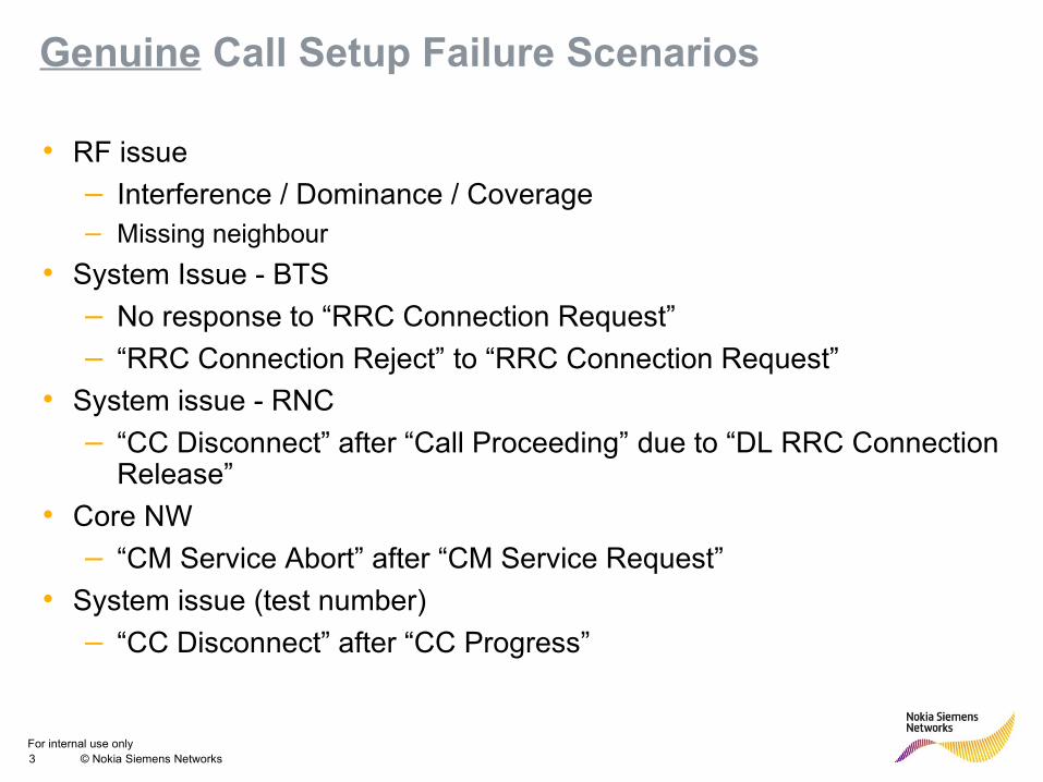
Genuine Call Setup Failure Scenarios
• RF issue
– Interference / Dominance / Coverage– Missing neighbour
• System Issue - BTS
– No response to “RRC Connection Request”
– “RRC Connection Reject” to “RRC Connection Request”
• System issue - RNC
– “CC Disconnect” after “Call Proceeding” due to “DL RRC Connection Release”
• Core NW
– “CM Service Abort” after “CM Service Request”
• System issue (test number)
– “CC Disconnect” after “CC Progress”
For internal use only4 © Nokia Siemens Networks
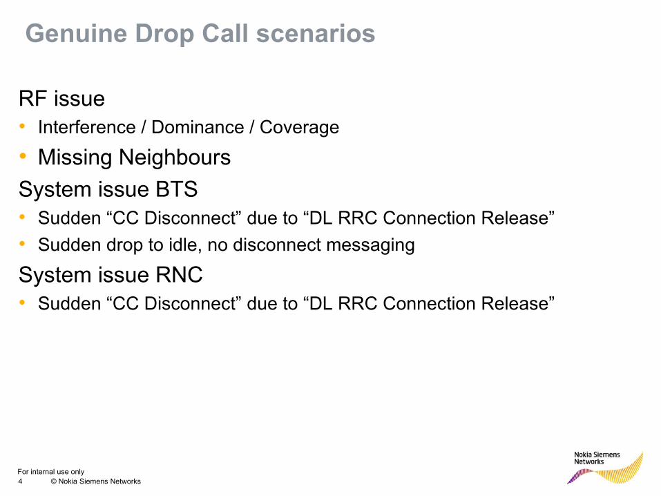
Genuine Drop Call scenarios
RF issue• Interference / Dominance / Coverage
• Missing Neighbours
System issue BTS• Sudden “CC Disconnect” due to “DL RRC Connection Release”
• Sudden drop to idle, no disconnect messaging
System issue RNC• Sudden “CC Disconnect” due to “DL RRC Connection Release”
For internal use only5 © Nokia Siemens Networks Presentation / Author / Date
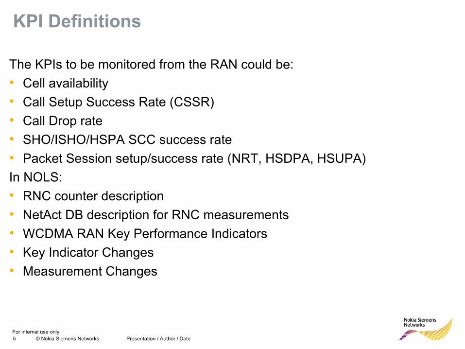
KPI Definitions
The KPIs to be monitored from the RAN could be:
• Cell availability
• Call Setup Success Rate (CSSR)
• Call Drop rate
• SHO/ISHO/HSPA SCC success rate
• Packet Session setup/success rate (NRT, HSDPA, HSUPA)
In NOLS:
• RNC counter description
• NetAct DB description for RNC measurements
• WCDMA RAN Key Performance Indicators
• Key Indicator Changes
• Measurement Changes
For internal use only6 © Nokia Siemens Networks
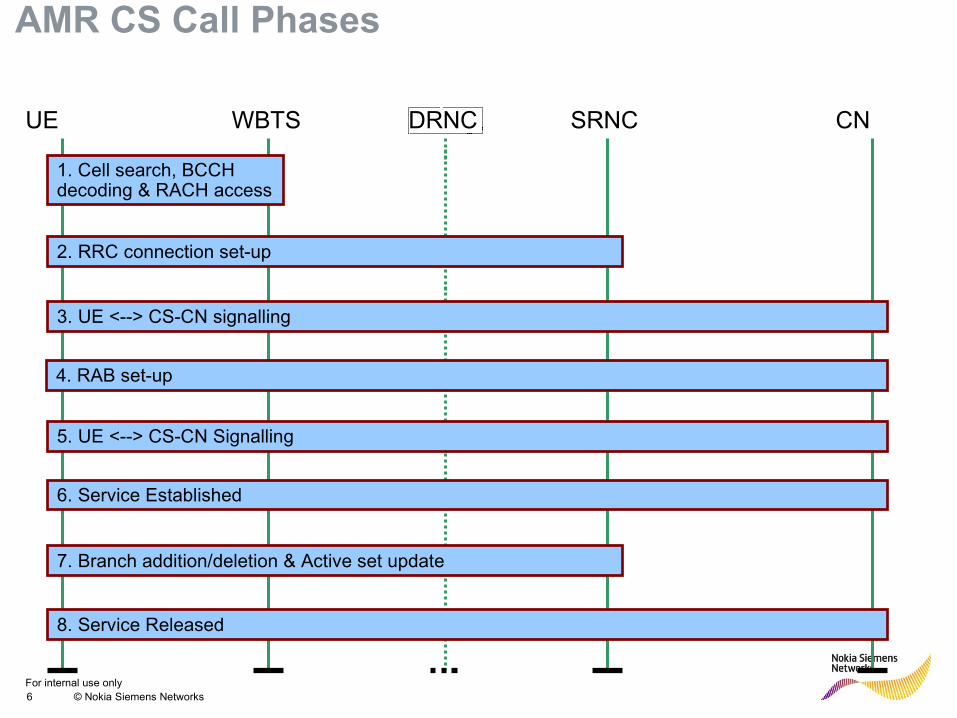
DRNCUE CNSRNCWBTS
2. RRC connection set-up
6. Service Established
7. Branch addition/deletion & Active set update
1. Cell search, BCCH decoding & RACH access
3. UE <--> CS-CN signalling
4. RAB set-up
8. Service Released
5. UE <--> CS-CN Signalling
AMR CS Call Phases
For internal use only7 © Nokia Siemens Networks
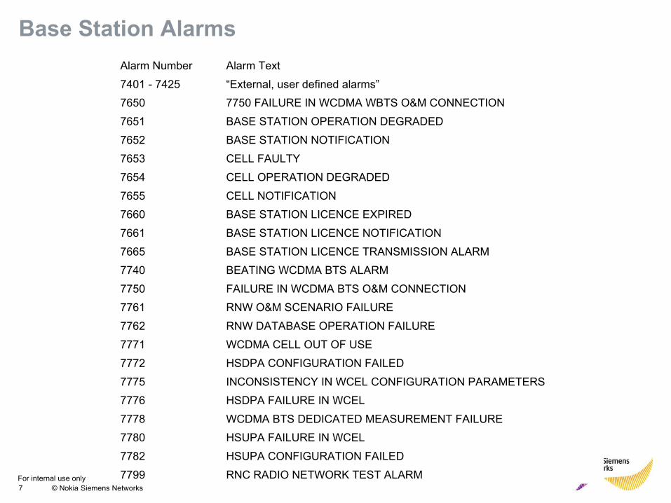
Base Station Alarms
Alarm Number Alarm Text
7401 - 7425 “External, user defined alarms”
7650 7750 FAILURE IN WCDMA WBTS O&M CONNECTION
7651 BASE STATION OPERATION DEGRADED
7652 BASE STATION NOTIFICATION
7653 CELL FAULTY
7654 CELL OPERATION DEGRADED
7655 CELL NOTIFICATION
7660 BASE STATION LICENCE EXPIRED
7661 BASE STATION LICENCE NOTIFICATION
7665 BASE STATION LICENCE TRANSMISSION ALARM
7740 BEATING WCDMA BTS ALARM
7750 FAILURE IN WCDMA BTS O&M CONNECTION
7761 RNW O&M SCENARIO FAILURE
7762 RNW DATABASE OPERATION FAILURE
7771 WCDMA CELL OUT OF USE
7772 HSDPA CONFIGURATION FAILED
7775 INCONSISTENCY IN WCEL CONFIGURATION PARAMETERS
7776 HSDPA FAILURE IN WCEL
7778 WCDMA BTS DEDICATED MEASUREMENT FAILURE
7780 HSUPA FAILURE IN WCEL
7782 HSUPA CONFIGURATION FAILED
7799 RNC RADIO NETWORK TEST ALARM
For internal use only8 © Nokia Siemens Networks
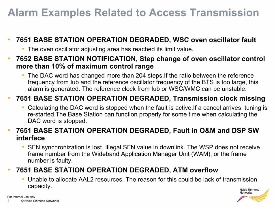
Alarm Examples Related to Access Transmission
• 7651 BASE STATION OPERATION DEGRADED, WSC oven oscillator fault• The oven oscillator adjusting area has reached its limit value.
• 7652 BASE STATION NOTIFICATION, Step change of oven oscillator control more than 10% of maximum control range
• The DAC word has changed more than 204 steps.If the ratio between the reference frequency from Iub and the reference oscillator frequency of the BTS is too large, this alarm is generated. The reference clock from Iub or WSC/WMC can be unstable.
• 7651 BASE STATION OPERATION DEGRADED, Transmission clock missing• Calculating the DAC word is stopped when the fault is active.If a cancel arrives, tuning is
re-started.The Base Station can function properly for some time when calculating the DAC word is stopped.
• 7651 BASE STATION OPERATION DEGRADED, Fault in O&M and DSP SW interface
• SFN synchronization is lost. Illegal SFN value in downlink. The WSP does not receive frame number from the Wideband Application Manager Unit (WAM), or the frame number is faulty.
• 7651 BASE STATION OPERATION DEGRADED, ATM overflow• Unable to allocate AAL2 resources. The reason for this could be lack of transmission
capacity.
For internal use only9 © Nokia Siemens Networks
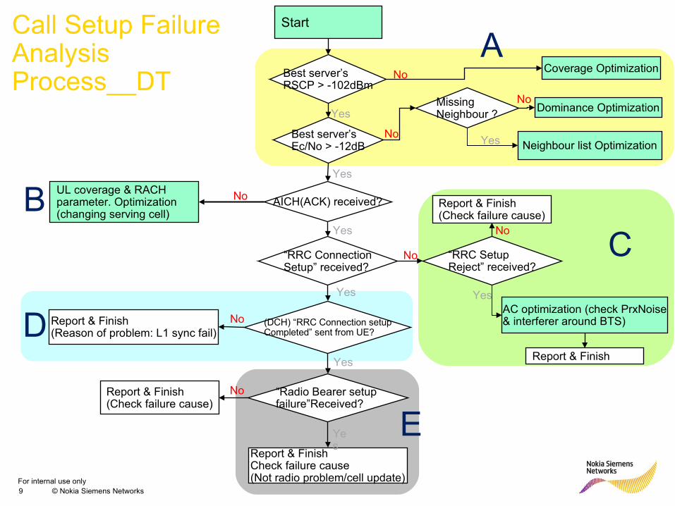
Start
Best server’s RSCP > -102dBm
Best server’s Ec/No > -12dB
Coverage Optimization
Dominance Optimization
AICH(ACK) received?
YesMissing Neighbour ?
Neighbour list Optimization
No
No
No
Yes
UL coverage & RACH parameter. Optimization(changing serving cell)
“RRC ConnectionSetup” received?
(DCH) “RRC Connection setupCompleted” sent from UE?
“Radio Bearer setup failure”Received?
Report & FinishCheck failure cause (Not radio problem/cell update)
Report & Finish(Check failure cause)
AC optimization (check PrxNoise& interferer around BTS)
Report & Finish
“RRC Setup Reject” received?
Yes
No
Yes
Yes
Yes
Report & Finish (Reason of problem: L1 sync fail)
Report & Finish(Check failure cause)
Call Setup Failure Analysis Process__DT
A
BC
D
E
Yes
Yes
No
No
No
No
For internal use only10 © Nokia Siemens Networks
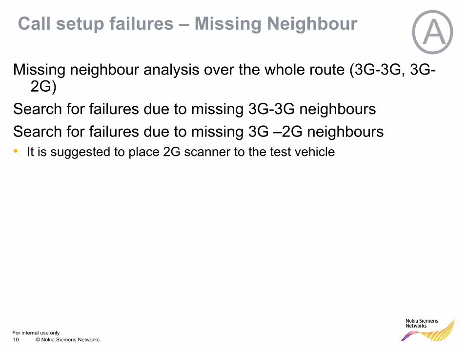
Call setup failures – Missing Neighbour AMissing neighbour analysis over the whole route (3G-3G, 3G-
2G)
Search for failures due to missing 3G-3G neighbours
Search for failures due to missing 3G –2G neighbours• It is suggested to place 2G scanner to the test vehicle
For internal use only11 © Nokia Siemens Networks
Call Setup Failure Analysis- Block B -
The purpose of this activity is to check the Random Access Process is working adequately by investigating whether AI (Acquisition Indicator) has been received through DL AICH
If AICH was not received by UE, the cause of the problem can be classified into:
• Inadequate RAN parameter related to Random Access: RAN parameter settings for pre-amble transmission or open loop power control information is not correct.
• UL Coverage limit: UL coverage of UE is smaller compared to serving cells DL coverage so that UE’s Tx power cannot reach serving cell.
B
For internal use only12 © Nokia Siemens Networks
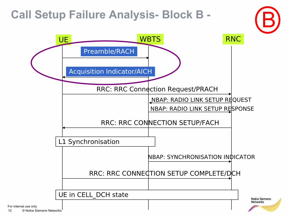
Call Setup Failure Analysis- Block B -
UE WBTS RNC
Preamble/RACH
Acquisition Indicator/AICH
RRC: RRC Connection Request/PRACH
NBAP: RADIO LINK SETUP REQUEST
RRC: RRC CONNECTION SETUP/FACH
L1 Synchronisation
NBAP: SYNCHRONISATION INDICATOR
RRC: RRC CONNECTION SETUP COMPLETE/DCH
UE in CELL_DCH state
NBAP: RADIO LINK SETUP RESPONSE
B
For internal use only13 © Nokia Siemens Networks
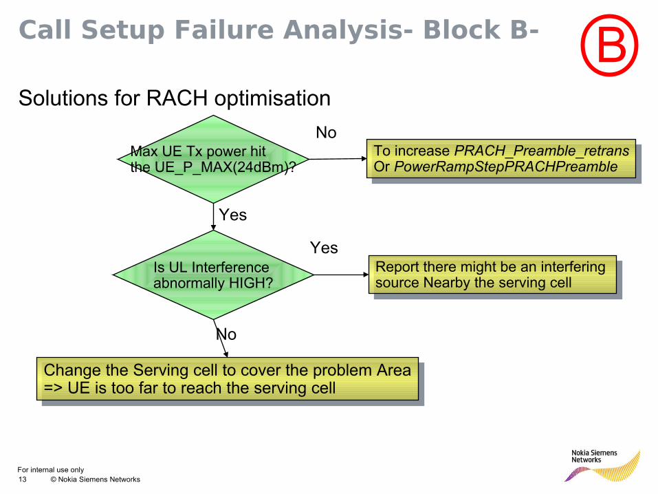
Call Setup Failure Analysis- Block B-
Solutions for RACH optimisation
Max UE Tx power hit the UE_P_MAX(24dBm)?
To increase PRACH_Preamble_retransOr PowerRampStepPRACHPreamble
To increase PRACH_Preamble_retransOr PowerRampStepPRACHPreamble
No
Yes
Is UL Interference abnormally HIGH?
Yes
No
Report there might be an interfering source Nearby the serving cell
Report there might be an interfering source Nearby the serving cell
Change the Serving cell to cover the problem Area=> UE is too far to reach the serving cell
Change the Serving cell to cover the problem Area=> UE is too far to reach the serving cell
B
For internal use only14 © Nokia Siemens Networks
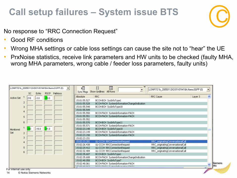
Call setup failures – System issue BTS
No response to “RRC Connection Request”
• Good RF conditions
• Wrong MHA settings or cable loss settings can cause the site not to “hear” the UE
• PrxNoise statistics, receive link parameters and HW units to be checked (faulty MHA, wrong MHA parameters, wrong cable / feeder loss parameters, faulty units)
C
For internal use only15 © Nokia Siemens Networks
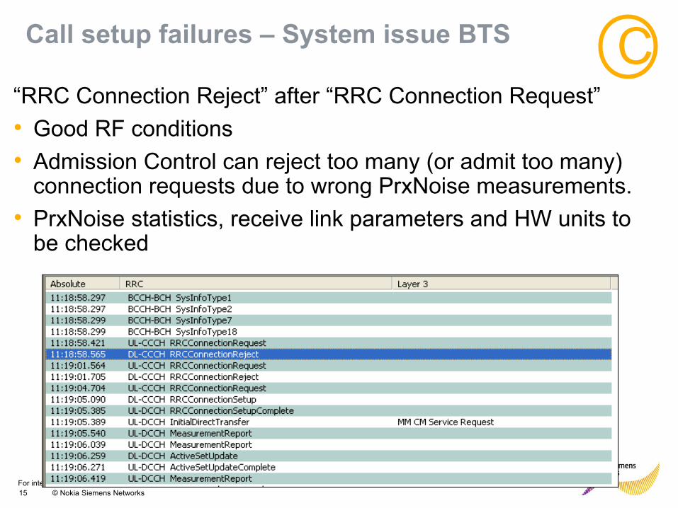
Call setup failures – System issue BTS
“RRC Connection Reject” after “RRC Connection Request”
• Good RF conditions
• Admission Control can reject too many (or admit too many) connection requests due to wrong PrxNoise measurements.
• PrxNoise statistics, receive link parameters and HW units to be checked
C
For internal use only16 © Nokia Siemens Networks
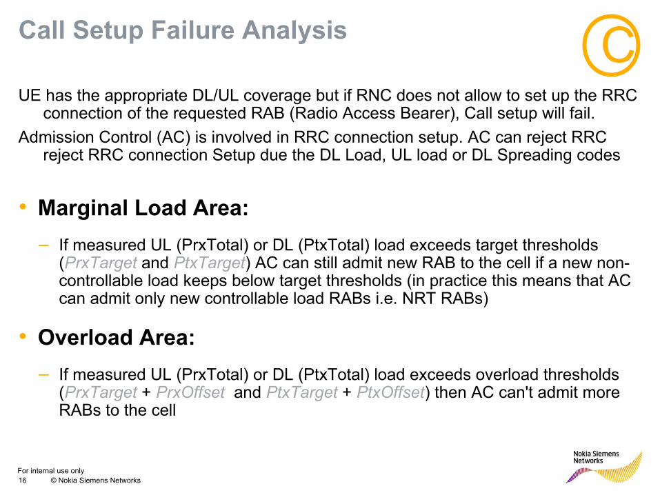
Call Setup Failure Analysis
UE has the appropriate DL/UL coverage but if RNC does not allow to set up the RRC connection of the requested RAB (Radio Access Bearer), Call setup will fail.
Admission Control (AC) is involved in RRC connection setup. AC can reject RRC reject RRC connection Setup due the DL Load, UL load or DL Spreading codes
• Marginal Load Area:
– If measured UL (PrxTotal) or DL (PtxTotal) load exceeds target thresholds (PrxTarget and PtxTarget) AC can still admit new RAB to the cell if a new non-controllable load keeps below target thresholds (in practice this means that AC can admit only new controllable load RABs i.e. NRT RABs)
• Overload Area:
– If measured UL (PrxTotal) or DL (PtxTotal) load exceeds overload thresholds (PrxTarget + PrxOffset and PtxTarget + PtxOffset) then AC can't admit more RABs to the cell
C
For internal use only17 © Nokia Siemens Networks
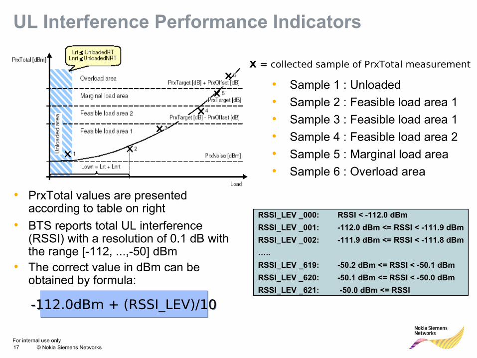
• PrxTotal values are presented according to table on right
• BTS reports total UL interference (RSSI) with a resolution of 0.1 dB with the range [-112, ...,-50] dBm
• The correct value in dBm can be obtained by formula:
-112.0dBm + (RSSI_LEV)/10-112.0dBm + (RSSI_LEV)/10
UL Interference Performance Indicators
• Sample 1 : Unloaded
• Sample 2 : Feasible load area 1
• Sample 3 : Feasible load area 1
• Sample 4 : Feasible load area 2
• Sample 5 : Marginal load area
• Sample 6 : Overload area
X = collected sample of PrxTotal measurement
RSSI_LEV _000: RSSI < -112.0 dBm
RSSI_LEV _001: -112.0 dBm <= RSSI < -111.9 dBm
RSSI_LEV _002: -111.9 dBm <= RSSI < -111.8 dBm
…..
RSSI_LEV _619: -50.2 dBm <= RSSI < -50.1 dBm
RSSI_LEV _620: -50.1 dBm <= RSSI < -50.0 dBm
RSSI_LEV _621: -50.0 dBm <= RSSI
For internal use only18 © Nokia Siemens Networks
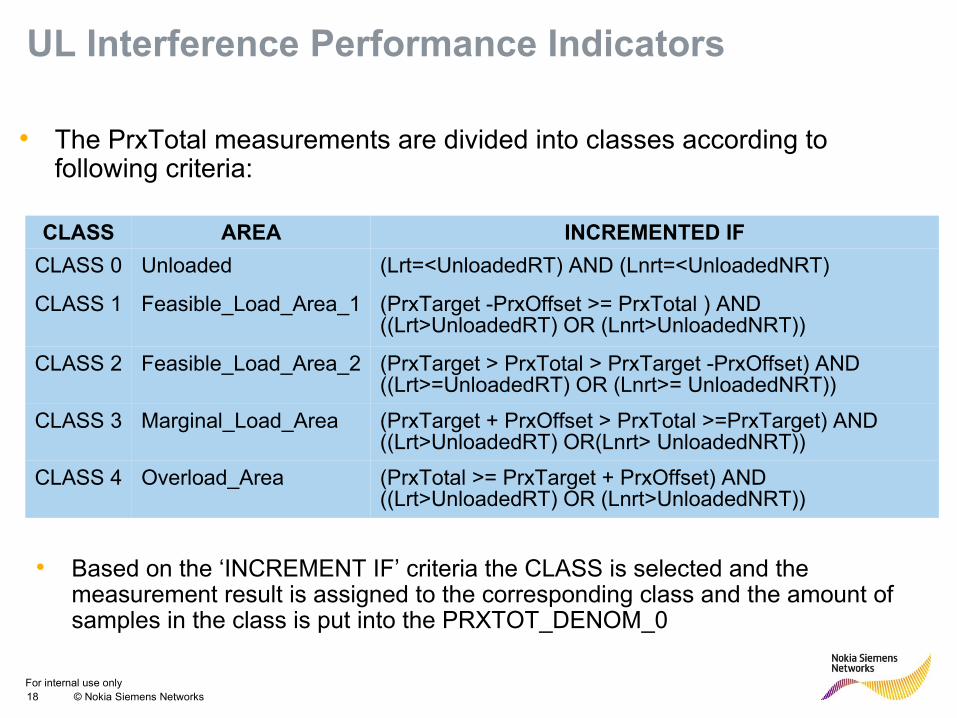
UL Interference Performance Indicators
• The PrxTotal measurements are divided into classes according to following criteria:
CLASS AREA INCREMENTED IF
CLASS 0 Unloaded (Lrt=<UnloadedRT) AND (Lnrt=<UnloadedNRT)
CLASS 1 Feasible_Load_Area_1 (PrxTarget -PrxOffset >= PrxTotal ) AND ((Lrt>UnloadedRT) OR (Lnrt>UnloadedNRT))
CLASS 2 Feasible_Load_Area_2 (PrxTarget > PrxTotal > PrxTarget -PrxOffset) AND ((Lrt>=UnloadedRT) OR (Lnrt>= UnloadedNRT))
CLASS 3 Marginal_Load_Area (PrxTarget + PrxOffset > PrxTotal >=PrxTarget) AND ((Lrt>UnloadedRT) OR(Lnrt> UnloadedNRT))
CLASS 4 Overload_Area (PrxTotal >= PrxTarget + PrxOffset) AND ((Lrt>UnloadedRT) OR (Lnrt>UnloadedNRT))
• Based on the ‘INCREMENT IF’ criteria the CLASS is selected and the measurement result is assigned to the corresponding class and the amount of samples in the class is put into the PRXTOT_DENOM_0
For internal use only19 © Nokia Siemens Networks
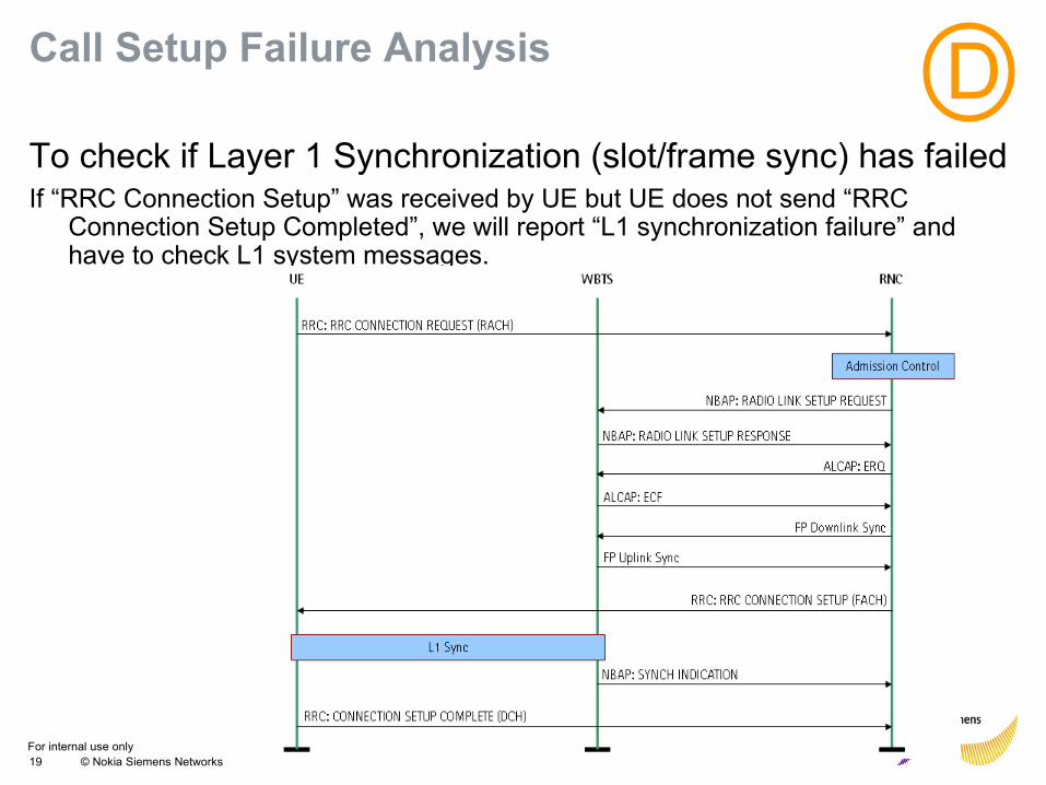
Call Setup Failure Analysis
To check if Layer 1 Synchronization (slot/frame sync) has failedIf “RRC Connection Setup” was received by UE but UE does not send “RRC
Connection Setup Completed”, we will report “L1 synchronization failure” and have to check L1 system messages.
D
For internal use only20 © Nokia Siemens Networks
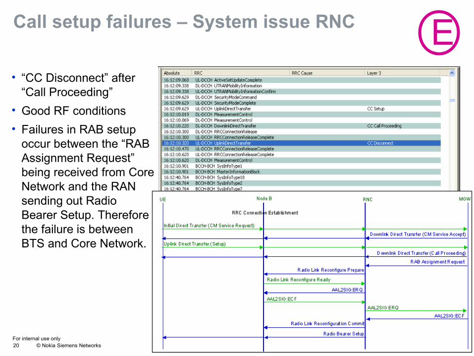
• “CC Disconnect” after “Call Proceeding”
• Good RF conditions
• Failures in RAB setup occur between the “RAB Assignment Request” being received from Core Network and the RAN sending out Radio Bearer Setup. Therefore the failure is between BTS and Core Network.
ECall setup failures – System issue RNC
For internal use only21 © Nokia Siemens Networks
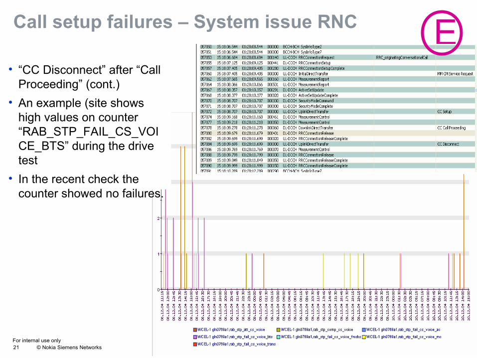
• “CC Disconnect” after “Call Proceeding” (cont.)
• An example (site shows high values on counter “RAB_STP_FAIL_CS_VOICE_BTS” during the drive test
• In the recent check the counter showed no failures.
ECall setup failures – System issue RNC
For internal use only22 © Nokia Siemens Networks
Call setup failures – Core NW
Security Mode Command
Common ID
UE RNC MGWNode B
RRC Connection Establishment
Initial Direct Transfer (CM Service Request) SCCP: Connection Request
SCCP: Connection ConfirmLocation Reporting Control
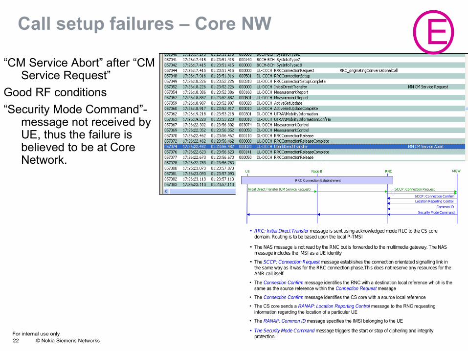
• RRC: Initial Direct Transfer message is sent using acknowledged mode RLC to the CS core domain. Routing is to be based upon the local P-TMSI
• The NAS message is not read by the RNC but is forwarded to the multimedia gateway. The NAS message includes the IMSI as a UE identity
• The SCCP: Connection Request message establishes the connection orientated signalling link in the same way as it was for the RRC connection phase.This does not reserve any resources for the AMR call itself.
• The Connection Confirm message identifies the RNC with a destination local reference which is the same as the source reference within the Connection Request message
• The Connection Confirm message identifies the CS core with a source local reference
• The CS core sends a RANAP: Location Reporting Control message to the RNC requesting information regarding the location of a particular UE
• The RANAP: Common ID message specifies the IMSI belonging to the UE
• The Security Mode Command message triggers the start or stop of ciphering and integrity protection.
“CM Service Abort” after “CM Service Request”
Good RF conditions
“Security Mode Command”-message not received by UE, thus the failure is believed to be at Core Network.
E
For internal use only24 © Nokia Siemens Networks Presentation / Author / Date
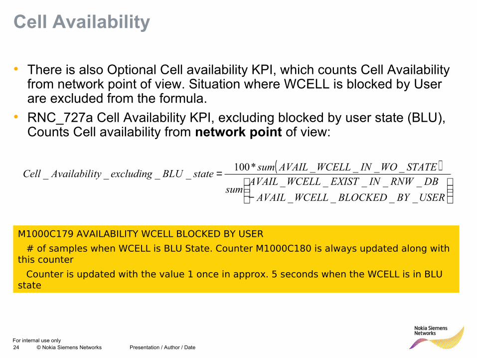
Cell Availability
• There is also Optional Cell availability KPI, which counts Cell Availability from network point of view. Situation where WCELL is blocked by User are excluded from the formula.
• RNC_727a Cell Availability KPI, excluding blocked by user state (BLU), Counts Cell availability from network point of view:
( )
−
=
USERBYBLOCKEDWCELLAVAIL
DBRNWINEXISTWCELLAVAILsum
STATEWOINWCELLAVAILsumstateBLUexcludingtyAvailabiliCell
____
_________*100
____
M1000C179 AVAILABILITY WCELL BLOCKED BY USER
• # of samples when WCELL is BLU State. Counter M1000C180 is always updated along with this counter
• Counter is updated with the value 1 once in approx. 5 seconds when the WCELL is in BLU state
For internal use only25 © Nokia Siemens Networks DNO Optimization Processes / JC Ejarque
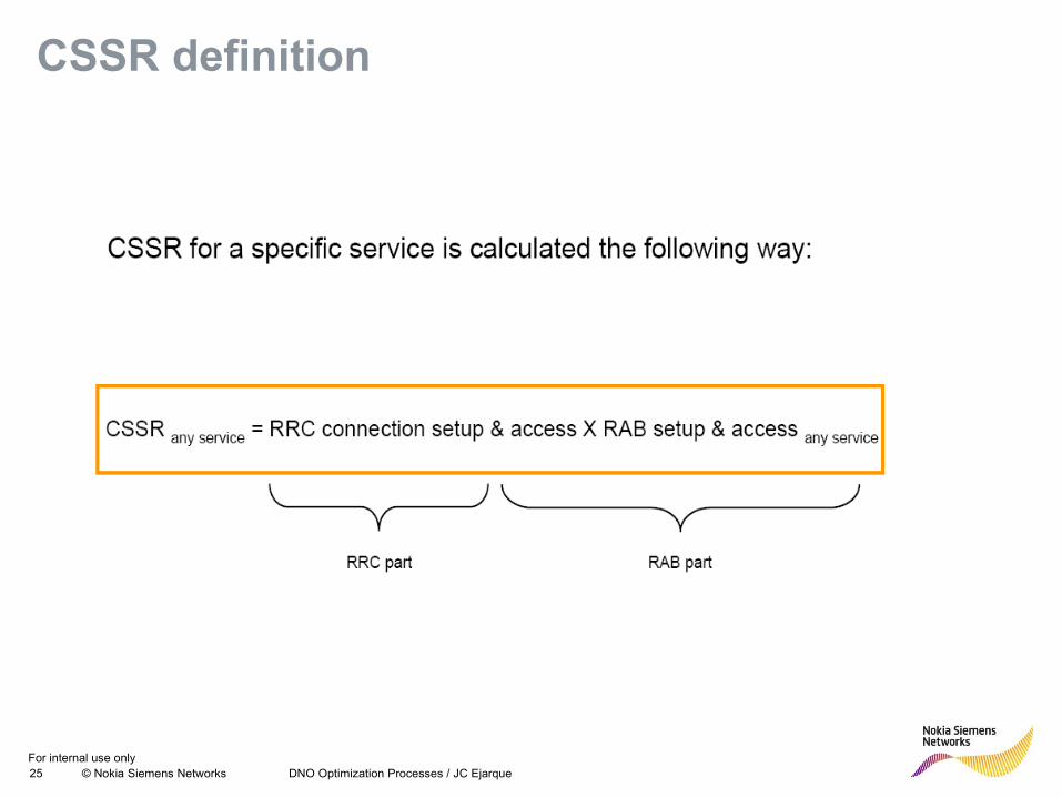
CSSR definition
For internal use only26 © Nokia Siemens Networks DNO Optimization Processes / JC Ejarque
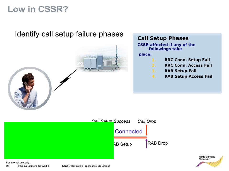
Low in CSSR?
Identify call setup failure phasesCall Setup PhasesCSSR affected if any of the
followings take place.
1. RRC Conn. Setup Fail2. RRC Conn. Access Fail3. RAB Setup Fail4. RAB Setup Access Fail
Call Setup Phase
RRC
Conn. Req
RRC
Conn. Setup
RRC
Conn. Acc
RRC
Conn. ActRAB Setup RAB Drop
Call Setup Success Call Drop
Connected
For internal use only27 © Nokia Siemens Networks DNO Optimization Processes / JC Ejarque
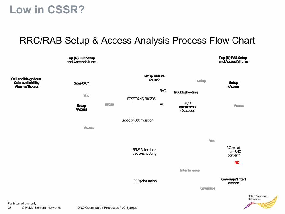
Low in CSSR?
RRC/RAB Setup & Access Analysis Process Flow Chart
Sites OK ? Cell and Neighbour
Cells availabilityAlarms/Tickets
Setup /Access
Yes
Setup /Access
Setup Failure Cause?
Capacity Optimisation
BTS/TRANS/FROZBSUL/DL
Interference (DL codes)
AC
TroubleshootingRNC
RF Optimisation
Top (N) RRC Setup and Access failures
Top (N) RAB Setup and Access failures
Coverage/Interference
setup
setup
Interference
Coverage
3G cell at inter-RNC border ?
SRNS Relocation troubleshooting
Yes
NO
Access
Access
For internal use only28 © Nokia Siemens Networks Presentation / Author / Date
Call Setup Success Rate (CSSR)
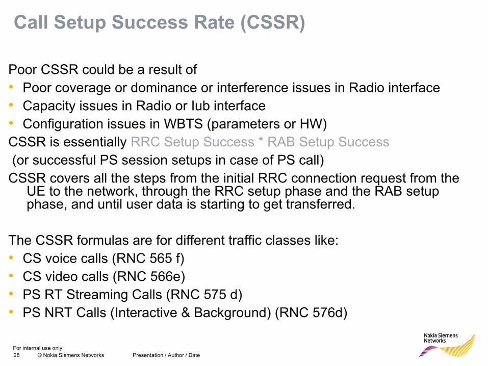
Poor CSSR could be a result of• Poor coverage or dominance or interference issues in Radio interface• Capacity issues in Radio or Iub interface• Configuration issues in WBTS (parameters or HW)CSSR is essentially RRC Setup Success * RAB Setup Success (or successful PS session setups in case of PS call)CSSR covers all the steps from the initial RRC connection request from the
UE to the network, through the RRC setup phase and the RAB setup phase, and until user data is starting to get transferred.
The CSSR formulas are for different traffic classes like: • CS voice calls (RNC 565 f)• CS video calls (RNC 566e)• PS RT Streaming Calls (RNC 575 d) • PS NRT Calls (Interactive & Background) (RNC 576d)
For internal use only29 © Nokia Siemens Networks Presentation / Author / Date
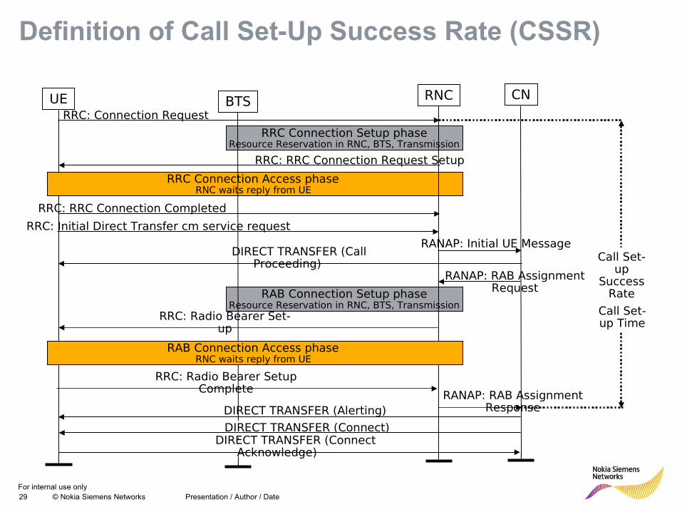
UERRC: Connection Request
RRC Connection Setup phaseResource Reservation in RNC, BTS, Transmission
RRC: RRC Connection Request Setup
RRC Connection Access phase RNC waits reply from UE
RRC: RRC Connection Completed
RRC: Initial Direct Transfer cm service request
RANAP: Initial UE MessageDIRECT TRANSFER (Call
Proceeding)RANAP: RAB Assignment
Request
RRC: Radio Bearer Set-up
RRC: Radio Bearer Setup Complete
RAB Connection Setup phaseResource Reservation in RNC, BTS, Transmission
RANAP: RAB Assignment ResponseDIRECT TRANSFER (Alerting)
BTS RNC CN
DIRECT TRANSFER (Connect)DIRECT TRANSFER (Connect
Acknowledge)
RAB Connection Access phase RNC waits reply from UE
Call Set-up
Success Rate
Call Set-up Time
Definition of Call Set-Up Success Rate (CSSR)
For internal use only30 © Nokia Siemens Networks
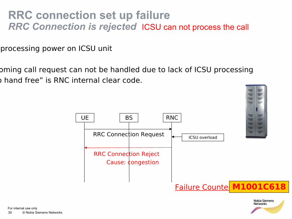
RRC connection set up failureRRC Connection is rejected ICSU can not process the call
No processing power on ICSU unit
Incoming call request can not be handled due to lack of ICSU processing
“No hand free” is RNC internal clear code.
RRC Connection Reject
Cause: congestion
UE BS RNC
RRC Connection RequestICSU overload
Failure CounterM1001C618
For internal use only31 © Nokia Siemens Networks Presentation / Author / Date
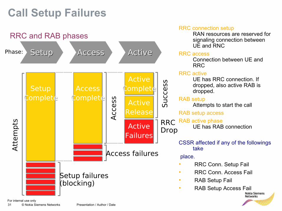
Call Setup FailuresRRC connection setup
RAN resources are reserved for signaling connection between UE and RNC
RRC accessConnection between UE and RRC
RRC activeUE has RRC connection. If dropped, also active RAB is dropped.
RAB setupAttempts to start the call
RAB setup access
RAB active phaseUE has RAB connection
CSSR affected if any of the followings take
place.
• RRC Conn. Setup Fail
• RRC Conn. Access Fail
• RAB Setup Fail
• RAB Setup Access Fail
SetupComplete
SetupComplete
AccessComplete
AccessComplete
ActiveComplete
ActiveComplete
SetupSetup AccessAccess ActiveActive
Att
em
pts
Setup failures(blocking)
Access failures
Acc
ess Active
ReleaseActive
Release
ActiveFailuresActive
Failures
RRCDrop
Succ
ess
Phase:
RRC and RAB phases
For internal use only32 © Nokia Siemens Networks
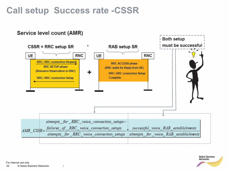
Call setup Success rate -CSSR
/
For internal use only33 © Nokia Siemens Networks Presentation / Author / Date
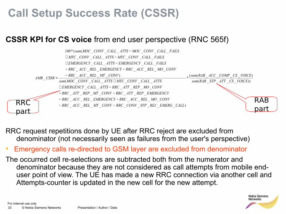
Call Setup Success Rate (CSSR)
CSSR KPI for CS voice from end user perspective (RNC 565f)
RRC request repetitions done by UE after RRC reject are excluded from denominator (not necessarily seen as failures from the user's perspective)
• Emergency calls re-directed to GSM layer are excluded from denominator
The occurred cell re-selections are subtracted both from the numerator and denominator because they are not considered as call attempts from mobile end-user point of view. The UE has made a new RRC connection via another cell and Attempts-counter is updated in the new cell for the new attempt.
))____(
)____((*
)_________
_______
_______
______
______(
)____
_______
____
______
______((*100
_VOICECSATTSTPRABsum
VOICECSCOMPACCRABsum
CALLEMERGREJSTPCONNRRCCONVMTRELACCRRC
CONVMORELACCRRCEMERGENCYRELACCRRC
EMERGENCYREPATTRRCCONVMTREPATTRRC
CONVMOREPATTRRCATTSCALLEMERGENCY
ATTSCALLCONVMTCATTSCALLCONVMOCsum
CONVMTRELACCRRC
CONVMORELACCRRCEMERGENCYRELACCRRC
FAILSCALLEMERGENCYATTSCALLEMERGENCY
FAILSCALLCONVMTCATTSCALLCONVMTC
FAILSCALLCONVMOCATTSCALLCONVMOCsum
CSSRAMR
−−−−
−−−+
+−
−−−+
−+−
=
RRC part
RAB part
For internal use only34 © Nokia Siemens Networks
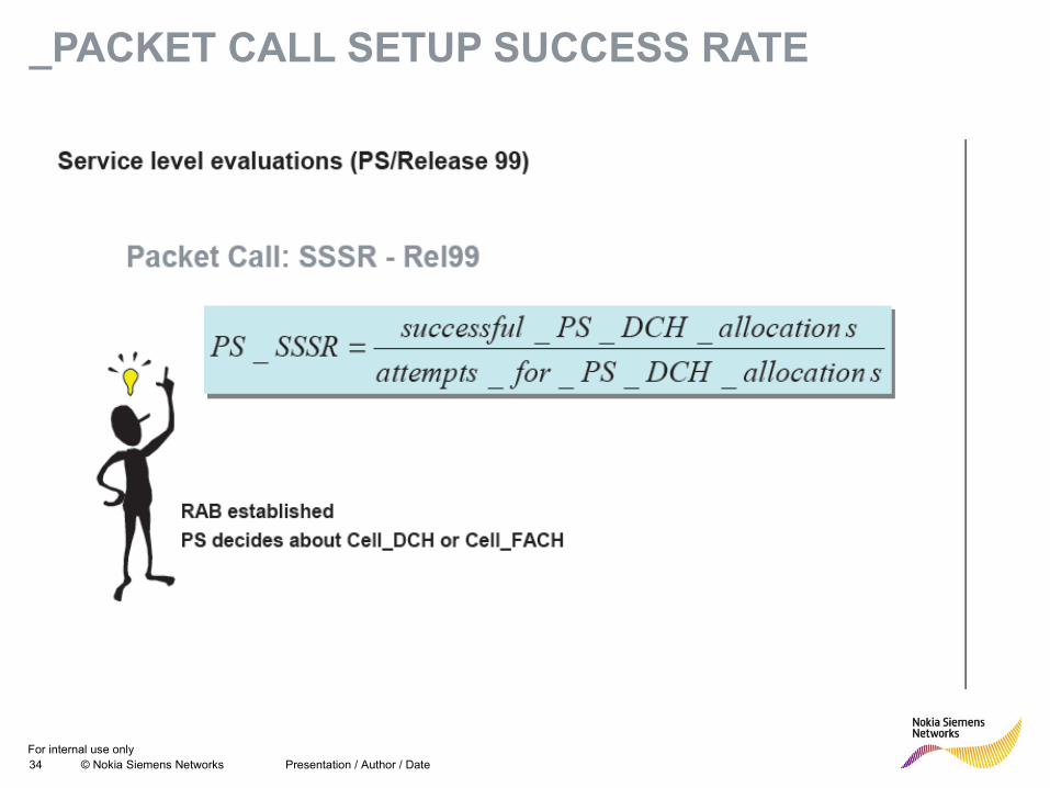
_PACKET CALL SETUP SUCCESS RATE
Presentation / Author / Date
For internal use only35 © Nokia Siemens Networks Presentation / Author / Date
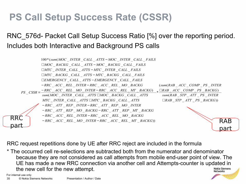
PS Call Setup Success Rate (CSSR)
RNC_576d- Packet Call Setup Success Ratio [%] over the reporting period.
Includes both Interactive and Background PS calls
RRC request repetitions done by UE after RRC reject are included in the formula
* The occurred cell re-selections are subtracted both from the numerator and denominator because they are not considered as call attempts from mobile end-user point of view. The UE has made a new RRC connection via another cell and Attempts-counter is updated in the new cell for the new attempt.
))____
____(
)____
____((
*
))________
_______
________
_______
______
______(
)________
_______
____
______
______
______
______((*100
_
BACKGPSATTSTPRAB
INTERPSATTSTPRABsum
BACKGPSCOMPACCRAB
INTERPSCOMPACCRABsum
BACKGMTRELACCRRCINTERMORELACCRRC
BACKGMORELACCRRCINTERRELACCRRC
BACKGMTREPATTRRCBACKGMOREPATTRRC
INTERMOREPATTRRCINTERREPATTRRC
ATTSCALLBACKGMTCATTSCALLINTERMTC
ATTSCALLBACKGMOCATTSCALLINTERMOCsum
BACKGMTRELACCRRCINTERMORELACCRRC
BACKGMORELACCRRCINTERRELACCRRC
FAILSCALLEMERGENCYATTSCALLEMERGENCY
FAILSCALLBACKGMTCATTSCALLBACKGMTC
FAILSCALLINTERMTCATTSCALLINTERMTC
FAILSCALLBACKGMOCATTSCALLBACKGMOC
FAILSCALLINTERMOCATTSCALLINTERMOCsum
CSSRPS
+
+
−−−−
−−−−+
+−−
−−−+−+
−+−+
−
=
RRC part
RAB part
For internal use only36 © Nokia Siemens Networks DNO Optimization Processes / JC Ejarque
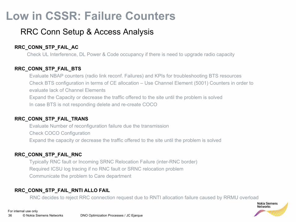
Low in CSSR: Failure CountersRRC Conn Setup & Access Analysis
RRC_CONN_STP_FAIL_AC
Check UL Interference, DL Power & Code occupancy if there is need to upgrade radio capacity
RRC_CONN_STP_FAIL_BTS
Evaluate NBAP counters (radio link reconf. Failures) and KPIs for troubleshooting BTS resources
Check BTS configuration in terms of CE allocation – Use Channel Element (5001) Counters in order to
evaluate lack of Channel Elements
Expand the Capacity or decrease the traffic offered to the site until the problem is solved
In case BTS is not responding delete and re-create COCO
RRC_CONN_STP_FAIL_TRANS
Evaluate Number of reconfiguration failure due the transmission
Check COCO Configuration
Expand the capacity or decrease the traffic offered to the site until the problem is solved
RRC_CONN_STP_FAIL_RNC
Typically RNC fault or Incoming SRNC Relocation Failure (inter-RNC border)
Required ICSU log tracing if no RNC fault or SRNC relocation problem
Communicate the problem to Care department
RRC_CONN_STP_FAIL_RNTI ALLO FAIL
RNC decides to reject RRC connection request due to RNTI allocation failure caused by RRMU overload
For internal use only37 © Nokia Siemens Networks DNO Optimization Processes / JC Ejarque
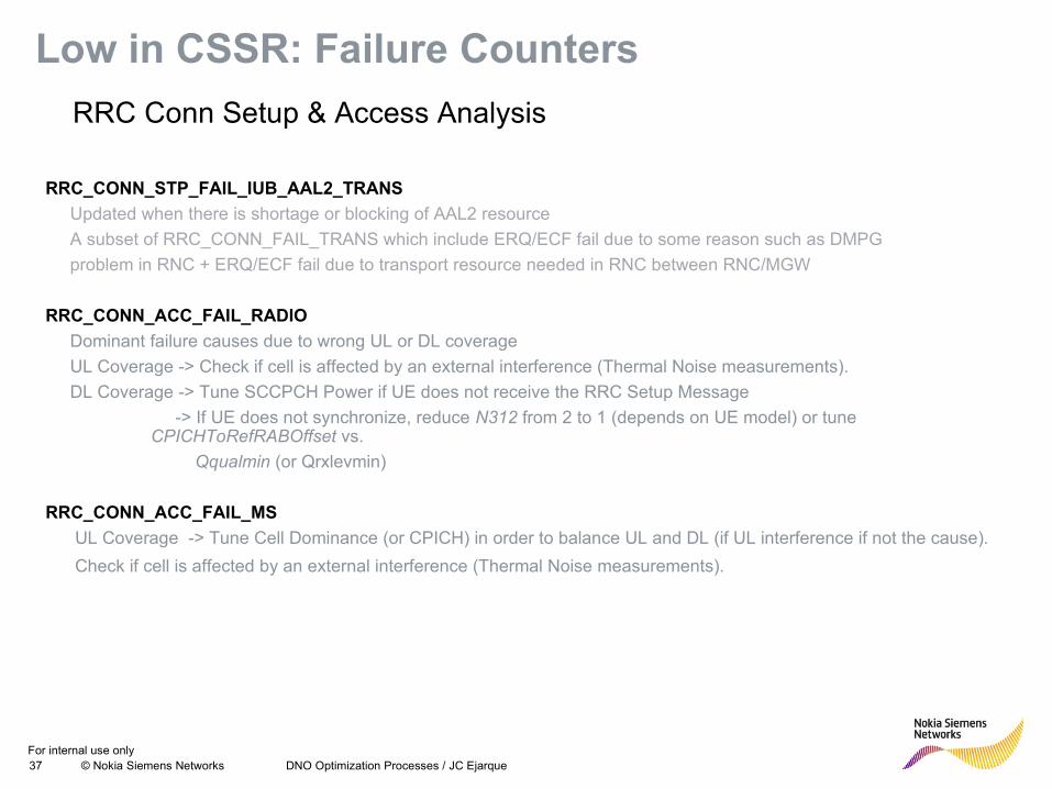
Low in CSSR: Failure Counters
RRC Conn Setup & Access Analysis
RRC_CONN_STP_FAIL_IUB_AAL2_TRANS
Updated when there is shortage or blocking of AAL2 resource
A subset of RRC_CONN_FAIL_TRANS which include ERQ/ECF fail due to some reason such as DMPG
problem in RNC + ERQ/ECF fail due to transport resource needed in RNC between RNC/MGW
RRC_CONN_ACC_FAIL_RADIO
Dominant failure causes due to wrong UL or DL coverage
UL Coverage -> Check if cell is affected by an external interference (Thermal Noise measurements).
DL Coverage -> Tune SCCPCH Power if UE does not receive the RRC Setup Message
-> If UE does not synchronize, reduce N312 from 2 to 1 (depends on UE model) or tune CPICHToRefRABOffset vs.
Qqualmin (or Qrxlevmin)
RRC_CONN_ACC_FAIL_MS
UL Coverage -> Tune Cell Dominance (or CPICH) in order to balance UL and DL (if UL interference if not the cause).
Check if cell is affected by an external interference (Thermal Noise measurements).
For internal use only38 © Nokia Siemens Networks DNO Optimization Processes / JC Ejarque
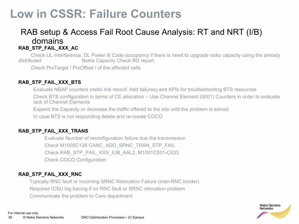
Low in CSSR: Failure Counters
RAB setup & Access Fail Root Cause Analysis: RT and NRT (I/B) domains
RAB_STP_FAIL_XXX_AC
Check UL Interference, DL Power & Code occupancy if there is need to upgrade radio capacity using the already distributed Nokia Capacity Check BO report.
Check PrxTarget / PrxOffset / of the affected cells
RAB_STP_FAIL_XXX_BTS
Evaluate NBAP counters (radio link reconf. Add failures) and KPIs for troubleshooting BTS resources
Check BTS configuration in terms of CE allocation – Use Channel Element (5001) Counters in order to evaluate lack of Channel Elements
Expand the Capacity or decrease the traffic offered to the site until the problem is solved.
In case BTS is not responding delete and re-create COCO
RAB_STP_FAIL_XXX_TRANS
Evaluate Number of reconfiguration failure due the transmission
Check M1005C128 CANC_ADD_SRNC_TRAN_STP_FAIL
Check RAB_STP_FAIL_XXX_IUB_AAL2, M1001C531-C533
Check COCO Configuration
RAB_STP_FAIL_XXX_RNC
Typically RNC fault or Incoming SRNC Relocation Failure (inter-RNC border)
Required ICSU log tracing if no RNC fault or SRNC relocation problem
Communicate the problem to Care department
For internal use only39 © Nokia Siemens Networks DNO Optimization Processes / JC Ejarque
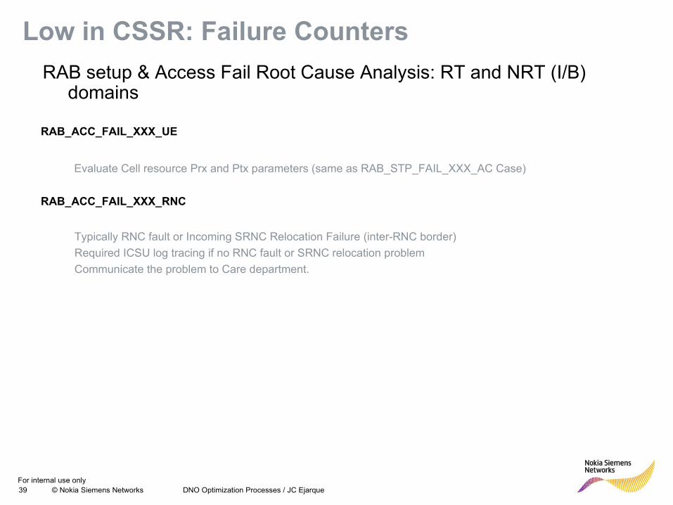
Low in CSSR: Failure Counters
RAB setup & Access Fail Root Cause Analysis: RT and NRT (I/B) domains
RAB_ACC_FAIL_XXX_UE
Evaluate Cell resource Prx and Ptx parameters (same as RAB_STP_FAIL_XXX_AC Case)
RAB_ACC_FAIL_XXX_RNC
Typically RNC fault or Incoming SRNC Relocation Failure (inter-RNC border)
Required ICSU log tracing if no RNC fault or SRNC relocation problem
Communicate the problem to Care department.
For internal use only40 © Nokia Siemens Networks DNO Optimization Processes / JC Ejarque
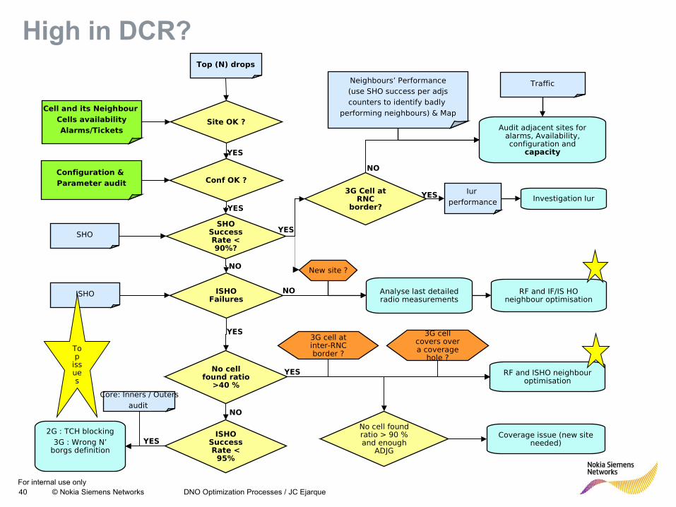
Top (N) drops
Cell and its Neighbour Cells availabilityAlarms/Tickets
Configuration & Parameter audit
SHO Success Rate < 90%?
Conf OK ?
Site OK ?
ISHO Failures
Iur performance Investigation Iur
Audit adjacent sites for alarms, Availability, configuration and
capacity
TrafficNeighbours’ Performance (use SHO success per adjs counters to identify badly
performing neighbours) & Map
3G Cell at RNC
border?
NO
YES
New site ?
Analyse last detailed radio measurements
RF and IF/IS HO neighbour optimisation
No cell found ratio
>40 %
ISHO Success Rate < 95%
RF and ISHO neighbour optimisation
3G cell covers over a coverage
hole ?
3G cell at inter-RNC border ?
Coverage issue (new site needed)
No cell found ratio > 90 % and enough
ADJG
Core: Inners / Outersaudit
2G : TCH blocking3G : Wrong N’
borgs definition
NO
YES
YES
YES
NO
YES
NO
YES
YES
SHO
ISHO
Top
issues
High in DCR?
For internal use only41 © Nokia Siemens Networks Presentation / Author / Date
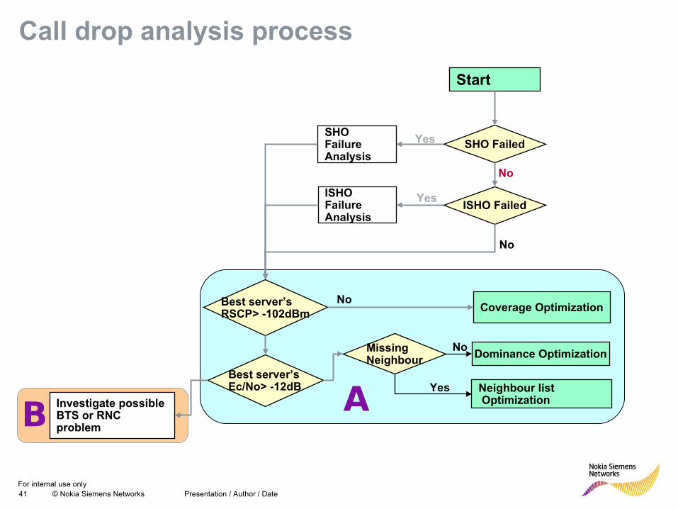
Call drop analysis process
Start
Best server’s RSCP> -102dBm
Best server’s Ec/No> -12dB
Coverage Optimization
Dominance Optimization
Yes Neighbour list Optimization
Missing Neighbour
Yes
SHO Failed
Investigate possible BTS or RNC problem
NoISHO Failed
No
ISHO Failure Analysis
YesSHO Failure Analysis
No
No
No
AB
For internal use only42 © Nokia Siemens Networks Presentation / Author / Date
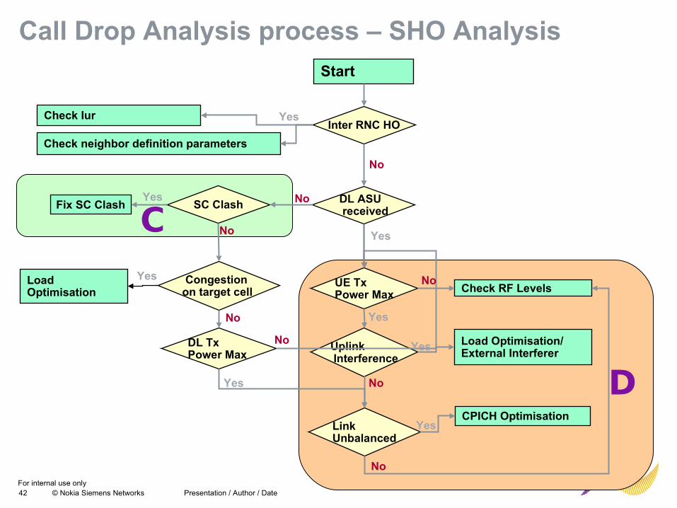
Call Drop Analysis process – SHO Analysis
DL ASU received
SC Clash
UE Tx Power Max
Fix SC Clash
CPICH Optimisation
Uplink Interference
Load Optimisation/ External Interferer
Link Unbalanced
Inter RNC HOCheck Iur
Congestion on target cell
Load Optimisation
Check neighbor definition parameters
Check RF Levels
DL Tx Power Max
Start
Yes
No
Yes
No
No
No
Yes
Yes
Yes
Yes
Yes
No
No
No
Yes
No
C
D
For internal use only43 © Nokia Siemens Networks Presentation / Author / Date
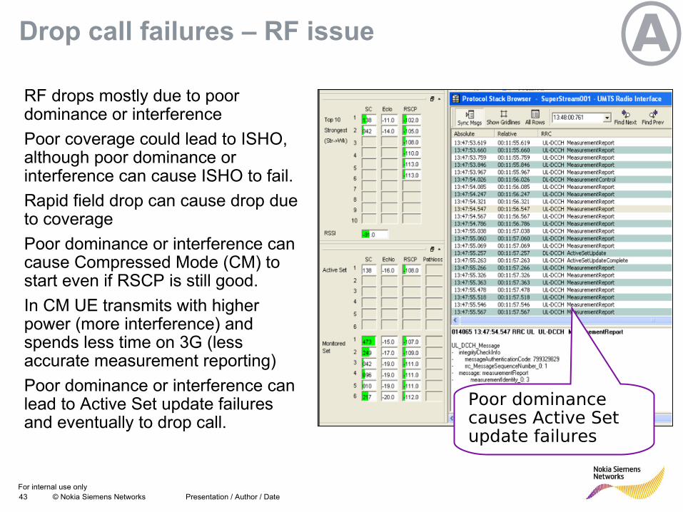
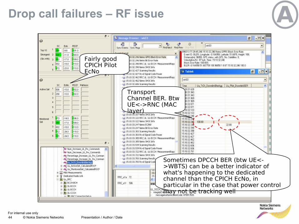
Drop call failures – RF issue
RF drops mostly due to poor dominance or interference
Poor coverage could lead to ISHO, although poor dominance or interference can cause ISHO to fail.
Rapid field drop can cause drop due to coverage
Poor dominance or interference can cause Compressed Mode (CM) to start even if RSCP is still good.
In CM UE transmits with higher power (more interference) and spends less time on 3G (less accurate measurement reporting)
Poor dominance or interference can lead to Active Set update failures and eventually to drop call.
Poor dominance causes Active Set update failures
A
For internal use only44 © Nokia Siemens Networks Presentation / Author / Date
Transport Channel BER. Btw UE<->RNC (MAC layer)
Sometimes DPCCH BER (btw UE<->WBTS) can be a better indicator of what's happening to the dedicated channel than the CPICH EcNo, in particular in the case that power control may not be tracking well
Fairly good CPICH Pilot EcNo
ADrop call failures – RF issue
For internal use only45 © Nokia Siemens Networks Presentation / Author / Date
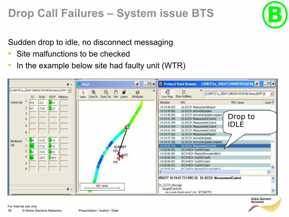
Drop Call Failures – System issue BTS BSudden drop to idle, no disconnect messaging
• Site malfunctions to be checked
• In the example below site had faulty unit (WTR)
Drop to IDLE
For internal use only46 © Nokia Siemens Networks Presentation / Author / Date
Sudden “RRC Connection Release”
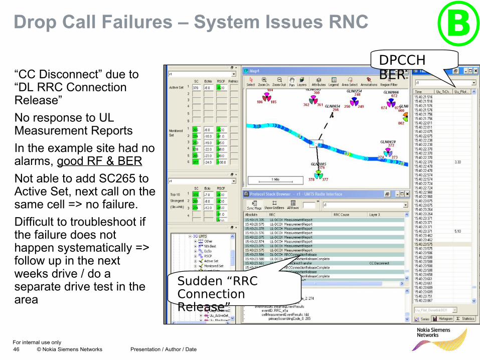
DPCCH BER“CC Disconnect” due to
“DL RRC Connection Release”
No response to UL Measurement Reports
In the example site had no alarms, good RF & BER
Not able to add SC265 to Active Set, next call on the same cell => no failure.
Difficult to troubleshoot if the failure does not happen systematically => follow up in the next weeks drive / do a separate drive test in the area
BDrop Call Failures – System Issues RNC
For internal use only47 © Nokia Siemens Networks Presentation / Author / Date
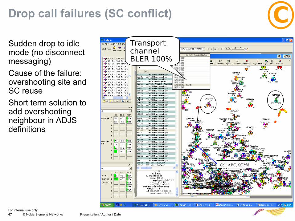
Drop call failures (SC conflict)
Sudden drop to idle mode (no disconnect messaging)
Cause of the failure: overshooting site and SC reuse
Short term solution to add overshooting neighbour in ADJS definitions
Cell ABC, SC258
Transport channel BLER 100%
C
For internal use only48 © Nokia Siemens Networks Presentation / Author / Date
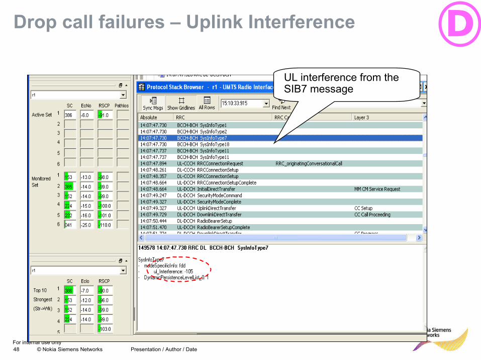
Drop call failures – Uplink Interference DUL interference from the SIB7 message
For internal use only49 © Nokia Siemens Networks Presentation / Author / Date
Drop call failures – System issue RNC or BTS ?
“CC Disconnect” due to “DL RRC Connection Release” is just a consequence of failure which can be due to different reasons
• From UE point of view L3-messaging does not identify the point of failure distinctly
• BTS or RNC failure? => Suspect BTS first, then RNC
Rule out BTS failures• Check the site performance from Counters (Iub, Service level, cell resources SHO,
etc) and that site is carrying traffic
• PrxNoise, receive link parameters, alarms
• SC–reuse
• UE performance ?
Identified causes for Active Set Update failure• “Deaf” sites (PrxNoise)
• Faulty HW
• SC-reuse
For internal use only50 © Nokia Siemens Networks DNO Optimization Processes / JC Ejarque
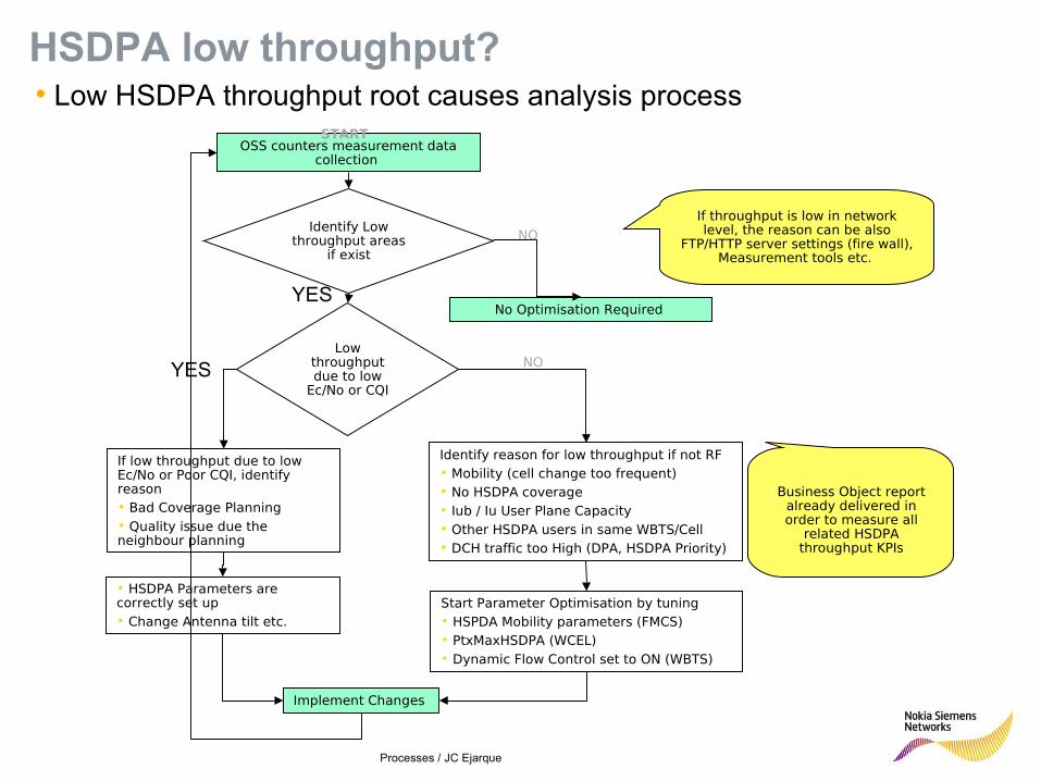
OSS counters measurement data collection
Identify Low throughput areas
if exist
Low throughput due to low
Ec/No or CQI
Identify reason for low throughput if not RF• Mobility (cell change too frequent)• No HSDPA coverage• Iub / Iu User Plane Capacity• Other HSDPA users in same WBTS/Cell• DCH traffic too High (DPA, HSDPA Priority)
Start Parameter Optimisation by tuning• HSPDA Mobility parameters (FMCS)• PtxMaxHSDPA (WCEL)• Dynamic Flow Control set to ON (WBTS)
If low throughput due to low Ec/No or Poor CQI, identify reason • Bad Coverage Planning• Quality issue due the neighbour planning
No Optimisation Required
Implement Changes
NO
• HSDPA Parameters are correctly set up• Change Antenna tilt etc.
START
NO
If throughput is low in network level, the reason can be also
FTP/HTTP server settings (fire wall), Measurement tools etc.
• Low HSDPA throughput root causes analysis process
HSDPA low throughput?
Business Object report already delivered in order to measure all
related HSDPA throughput KPIs
YES
YES
For internal use only51 © Nokia Siemens Networks
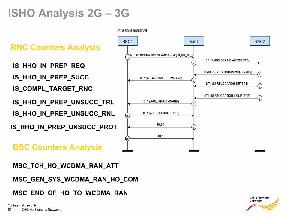
ISHO Analysis 2G – 3G
MSC_TCH_HO_WCDMA_RAN_ATT
IS_HHO_IN_PREP_SUCC
IS_HHO_IN_PREP_REQ
IS_COMPL_TARGET_RNC
BSC Counters Analysis
RNC Counters Analysis
MSC_END_OF_HO_TO_WCDMA_RAN
MSC_GEN_SYS_WCDMA_RAN_HO_COM
IS_HHO_IN_PREP_UNSUCC_TRL
IS_HHO_IN_PREP_UNSUCC_RNL
IS_HHO_IN_PREP_UNSUCC_PROT
For internal use only52 © Nokia Siemens Networks
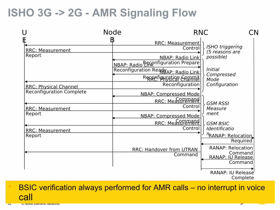
ISHO 3G -> 2G - AMR Signaling Flow
• BSIC verification always performed for AMR calls – no interrupt in voice call
CNUE
Node B
RNC
RRC: Measurement Report
RRC: Measurement Control
NBAP: Radio Link Reconfiguration PrepareNBAP: Radio Link
Reconfiguration ReadyNBAP: Radio Link Reconfiguration CommitRRC: Physical Channel
ReconfigurationRRC: Physical Channel Reconfiguration Complete NBAP: Compressed Mode
Command
RRC: Measurement Report
RRC: Measurement Control
NBAP: Compressed Mode Command
RRC: Measurement Report
RRC: Measurement Control
RRC: Handover from UTRAN Command
GSM BSIC Identification
GSM RSSI Measurement
ISHO triggering (5 reasons are possible)
Initial Compressed Mode Configuration
RANAP: Relocation Required
RANAP: Relocation Command
RANAP: IU Release Command
RANAP: IU Release Complete
For internal use only53 © Nokia Siemens Networks
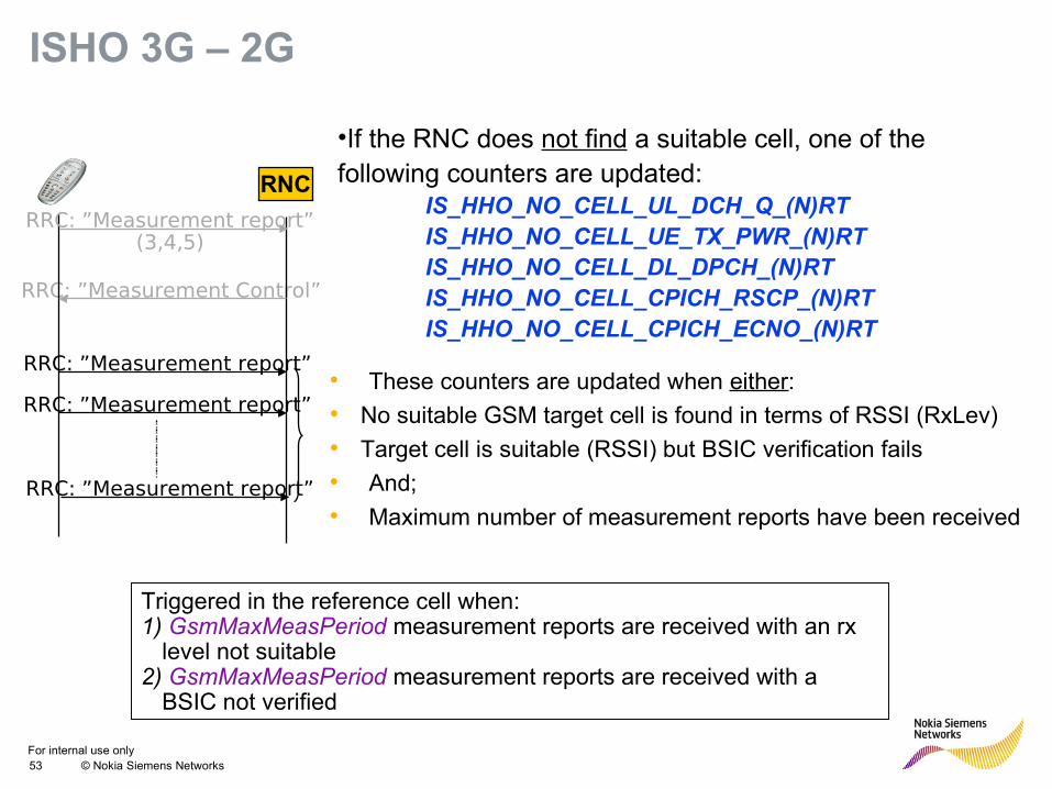
•If the RNC does not find a suitable cell, one of the following counters are updated:
IS_HHO_NO_CELL_UL_DCH_Q_(N)RTIS_HHO_NO_CELL_UE_TX_PWR_(N)RTIS_HHO_NO_CELL_DL_DPCH_(N)RTIS_HHO_NO_CELL_CPICH_RSCP_(N)RTIS_HHO_NO_CELL_CPICH_ECNO_(N)RT
Triggered in the reference cell when:1) GsmMaxMeasPeriod measurement reports are received with an rx
level not suitable 2) GsmMaxMeasPeriod measurement reports are received with a
BSIC not verified
RRC: ”Measurement Control”
RNC
RRC: ”Measurement report”
RRC: ”Measurement report”
RRC: ”Measurement report”
RRC: ”Measurement report”(3,4,5)
ISHO 3G – 2G
• These counters are updated when either:
• No suitable GSM target cell is found in terms of RSSI (RxLev)
• Target cell is suitable (RSSI) but BSIC verification fails
• And;
• Maximum number of measurement reports have been received
For internal use only54 © Nokia Siemens Networks Presentation / Author / Date
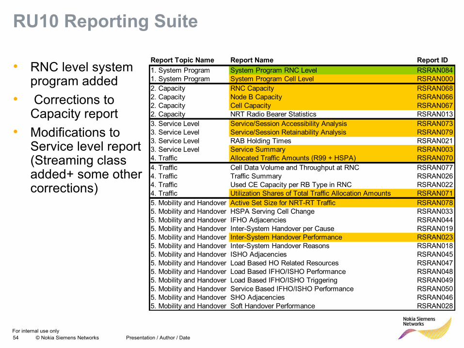
RU10 Reporting Suite
• RNC level system program added
• Corrections to Capacity report
• Modifications to Service level report (Streaming class added+ some other corrections)
Report Topic Name Report Name Report ID
1. System Program System Program RNC Level RSRAN0841. System Program System Program Cell Level RSRAN0002. Capacity RNC Capacity RSRAN0682. Capacity Node B Capacity RSRAN0662. Capacity Cell Capacity RSRAN0672. Capacity NRT Radio Bearer Statistics RSRAN0133. Service Level Service/Session Accessibility Analysis RSRAN0733. Service Level Service/Session Retainability Analysis RSRAN0793. Service Level RAB Holding Times RSRAN0213. Service Level Service Summary RSRAN0034. Traffic Allocated Traffic Amounts (R99 + HSPA) RSRAN0704. Traffic Cell Data Volume and Throughput at RNC RSRAN0774. Traffic Traffic Summary RSRAN0264. Traffic Used CE Capacity per RB Type in RNC RSRAN0224. Traffic Utilization Shares of Total Traffic Allocation Amounts RSRAN0715. Mobility and Handover Active Set Size for NRT-RT Traffic RSRAN0785. Mobility and Handover HSPA Serving Cell Change RSRAN0335. Mobility and Handover IFHO Adjacencies RSRAN0445. Mobility and Handover Inter-System Handover per Cause RSRAN0195. Mobility and Handover Inter-System Handover Performance RSRAN0235. Mobility and Handover Inter-System Handover Reasons RSRAN0185. Mobility and Handover ISHO Adjacencies RSRAN0455. Mobility and Handover Load Based HO Related Resources RSRAN0475. Mobility and Handover Load Based IFHO/ISHO Performance RSRAN0485. Mobility and Handover Load Based IFHO/ISHO Triggering RSRAN0495. Mobility and Handover Service Based IFHO/ISHO Performance RSRAN0505. Mobility and Handover SHO Adjacencies RSRAN0465. Mobility and Handover Soft Handover Performance RSRAN028
For internal use only55 © Nokia Siemens Networks Presentation / Author / Date
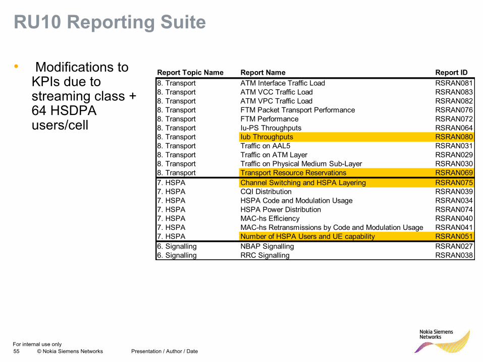
RU10 Reporting Suite
• Modifications to KPIs due to streaming class + 64 HSDPA users/cell
Report Topic Name Report Name Report ID
8. Transport ATM Interface Traffic Load RSRAN0818. Transport ATM VCC Traffic Load RSRAN0838. Transport ATM VPC Traffic Load RSRAN0828. Transport FTM Packet Transport Performance RSRAN0768. Transport FTM Performance RSRAN0728. Transport Iu-PS Throughputs RSRAN0648. Transport Iub Throughputs RSRAN0808. Transport Traffic on AAL5 RSRAN0318. Transport Traffic on ATM Layer RSRAN0298. Transport Traffic on Physical Medium Sub-Layer RSRAN0308. Transport Transport Resource Reservations RSRAN0697. HSPA Channel Switching and HSPA Layering RSRAN0757. HSPA CQI Distribution RSRAN0397. HSPA HSPA Code and Modulation Usage RSRAN0347. HSPA HSPA Power Distribution RSRAN0747. HSPA MAC-hs Efficiency RSRAN0407. HSPA MAC-hs Retransmissions by Code and Modulation Usage RSRAN0417. HSPA Number of HSPA Users and UE capability RSRAN0516. Signalling NBAP Signalling RSRAN0276. Signalling RRC Signalling RSRAN038
For internal use only56 © Nokia Siemens Networks
Summary• An understanding of the various signalling flows together with
the information contained in different messages and counters is an essential element in the optimisation engineers’ toolbox