WCDMA Basicss64f148b4acc3f5a3.jimcontent.com/download/version/1363761648/mod… · SPREADING...
22
WCDMA Basics Chapter 2 This chapter is designed to give the students a brief review of the WCDMA basics of the WCDMA Experimental System. This is meant as a review only as the WCDMA basics have already been covered in the WCDMA Overview course, LZU 108 3877, which is a prerequisite to this course. OBJECTIVES: Upon completion of this chapter the student will be able to: • Have access to reference information on the multiple access technologies TDMA, FDMA and CDMA • Have access to reference information on spreading and coding in the WCDMA Experimental System • Have access to reference information on DS-CDMA aspects such as:- power control, cell breathing, RAKE receiver and handover
-
Upload
nguyencong -
Category
Documents
-
view
220 -
download
3
Transcript of WCDMA Basicss64f148b4acc3f5a3.jimcontent.com/download/version/1363761648/mod… · SPREADING...

WCDMA Basics
Chapter 2
This chapter is designed to give the students a brief review ofthe WCDMA basics of the WCDMA Experimental System.This is meant as a review only as the WCDMA basics havealready been covered in the WCDMA Overview course, LZU108 3877, which is a prerequisite to this course.
OBJECTIVES:Upon completion of this chapter the student will be able to:
• Have access to reference information on the multiple accesstechnologies TDMA, FDMA and CDMA
• Have access to reference information on spreading andcoding in the WCDMA Experimental System
• Have access to reference information on DS-CDMA aspectssuch as:- power control, cell breathing, RAKE receiver andhandover

WCDMA Experimental System Survey
EN/LZT 123 4613 R2A
ll aa nn kkBB
iioonnaall llyy
ttnneettnnII

2 WCDMA Basics
EN/LZT 123 4613 R2A – i –
2 WCDMA Basics
Table of Contents
Topic Page
MULTIPLE ACCESS TECHNOLOGIES OVERVIEW..........................17
TRANSMISSION.......................................................................................................... 17
FDMA........................................................................................................................... 18
TDMA........................................................................................................................... 19
CDMA........................................................................................................................... 20
SPREADING ........................................................................................22
SPREADING PRINCIPLES ......................................................................................... 22
DS-CDMA ASPECTS...........................................................................29
POWER CONTROL..................................................................................................... 29
CELL BREATHING ...................................................................................................... 30
RAKE RECEIVER........................................................................................................ 30
HANDOVER (HARD, SOFT, SOFTER)....................................................................... 31
SUMMARY DESCRIPTION OF THE WCDMA EXPERIMENTALSYSTEM ACCESS TECHNIQUE.........................................................33

WCDMA Experimental System Survey
– ii – EN/LZT 123 4613 R2A
ll aa nn kkBB
iioonnaall llyy
ttnneettnnII

2 WCDMA Basics
EN/LZT 123 4613 R2A – 17 –
MULTIPLE ACCESS TECHNOLOGIES OVERVIEW
As an introduction to the radio access technology used in theWCDMA Experimental System, that is DS-CDMA (DirectSequence Code Division Multiple Access), a brief overview oftransmission and the following radio access technologies will begiven:
• Transmission
• Frequency Division Multiple Access (FDMA)
• Time Division Multiple Access (TDMA)
• Code Division Multiple Access (CDMA) in general andDirect Sequence CDMA (DS-CDMA) in particular
TRANSMISSION
Before introducing the multiple access methods as listed above,transmission will be discussed briefly. Modern digital mobilecommunication systems are full-duplex capable. Bi-directionalcommunication, that is (quasi-) simultaneous transmission andreceiving is possible.
Transmission can be in the Uplink (UL) direction and theDownlink (DL) direction. The UL is the transmission directionfrom the Mobile Station (MS) to the Base Transceiver Station(BTS). The DL designates the transmission direction from theBTS to the MS. In the United States this is usually called the‘reverse’ and ‘forward’ direction.
There are two different duplex transmission principles, i.e.Frequency Division Duplex (FDD) and Time Division Duplex(TDD).
In FDD, the UL and DL transmission takes place in differentfrequency bands which are separated from each other by aduplex distance.
In TDD, the UL and DL transmission are implemented in thesame frequency band and this band is divided into Time Slots(TSs). The UL and DL are separated by time and occur indifferent TSs.
In the following discussion on the access methods we will onlydiscuss the FDD duplex technique.

WCDMA Experimental System Survey
– 18 – EN/LZT 123 4613 R2A
FDMA
Frequency Division Multiple Access (FDMA) is very commonin the first generation of mobile communication systems, that isanalogue systems. The available spectrum in FDMA is dividedinto physical channels of equal bandwidth.
One physical channel is allocated per subscriber. The physicalchannel required for the transmission of one subscriber’sinformation uses FDD.
In pure FDMA systems different speech/data/signallingtransmissions can take place (per subscriber) at the same time ondifferent frequencies.
The physical channel allocated to the subscriber is used duringthe entire duration of the call and is unavailable for use byanother subscriber during that time. The physical channel isreleased at the end of the call where it is then made available forthe next subscriber who needs to make a call.
In summary, in FDMA narrow bandwidth is used as iscontinuous transmission and reception. There is orthogonality infrequency within the cell, that is different users use differentfrequencies in the cell. See Figure 2-1.
Frequency Division Multiple Access (FDMA)
Orthogonal in frequency within cell
Narrow bandwidth per carrier
Continuous transmission and reception
No synchronisation in time
f
t
Power
Figure 2-1 Frequency Division Multiple Access (FDMA)

2 WCDMA Basics
EN/LZT 123 4613 R2A – 19 –
TDMA
Note: When discussing Time Division Multiple Access(TDMA) in this section, it is the access technique that isdiscussed and not the standard.
TDMA is used in some digital systems and is normally used incombination with the FDMA method described above, forexample GSM and TDMA/D-AMPS) which uses FDD.
In TDMA, the available spectrum is divided in time into TimeSlots (TSs). The subscriber is allocated a TS and only that TScan be used during the time that is assigned to that subscriber. Aphysical channel in TDMA is defined as one TS and thesubscriber has cyclical access to it. The subscriber information(speech/ data/ signalling) is divided up and transmitted, bit bybit, via the assigned TS. The high frequency transmission ofeach TS is called a burst. A TS is typically in the order of amillisecond. TDMA requires strict timing of the bursttransmission in order to avoid overlapping of adjacent TSs. Thetime delay caused by the transmission of bursts (which have thefinite speed of light) is a problem in cellular systems with largecells. A very precise synchronization between the MS and theBTS is required. ‘Timing Advance’ information and ‘GuardPeriods’ between adjacent time slots prevent interference ofbursts of adjacent TSs. In summary, in TDMA there issyncronisation, increased bandwidth and increased peak power.The transmission and reception is discontinuous. There is alsoorthogonality in time within the cell, that is different users usethe spectrum at different times. See Figure 2-2.
Time Division Multiple Access (TDMA)
Orthogonal in time within cell
Increased bandwidth per carrier
Discontinuous transmission and reception
Increased peak power
Synchronisation in time
Power
t
f
Figure 2-2 Time Division Multiple Access (TDMA)

WCDMA Experimental System Survey
– 20 – EN/LZT 123 4613 R2A
CDMA
Code Division Multiple Access (CDMA) is used in some digitalsystems whereby many subscribers use the same frequency atthe same time. As all subscribers are using the same frequencyat the same time within the cell, there needs to be a way for eachsubscriber to find the information that is destined for him/her.In Direct Sequence CDMA (DS-CDMA), uniquely identifyinginformation for a particular subscriber is achieved by spreadingthe information. By spreading the information we mean we‘multiply’ the information with short and long codes. Spreadingand short and long codes will be explained in more detail in thesection on spreading below. The term WCDMA used in theWCDMA Experimental System means that CDMA is used as anaccess method.
CDMA is also known as a Spread Spectrum Technology.Spread Spectrum Technologies have been used since the 1940s,so it is not a new technology. In the 1940s it was mainly used bythe military so that the radio communication between differentmilitary groups could not be monitored or jammed by outsiders.More information on the usage of this technology by themilitary can be found in Appendix A.
CDMA can be further divided into Time Hopping CDMA (TH-CDMA), Frequency Hopping CDMA (FH-CDMA) and DirectSequence CDMA DS-CDMA. The main difference betweenthese CDMA methods is in the modulation techniques used togenerate the spread-spectrum signal. Modulation will bediscussed in more detail under the section QPSK below.
The difference between TH-CDMA and FH-CDMA is that inTH-CDMA the information-bearing signal is not transmitted ina continuous manner, but rather in short bursts and the time ofthe short bursts is decided by the spreading codes. In FH-CDMA, depending on the spreading codes used, the carrierfrequency at which the information-bearing signal is transmittedis changed rapidly. TH-DCMA and FH-CDMA are not used inthe WCDMA Experimental System.
As only DS-CDMA is used the Experimental System, only thistechnology and aspects relating to this technology will bediscussed further in the following sections.

2 WCDMA Basics
EN/LZT 123 4613 R2A – 21 –
Direct Sequence Code Division Multiple Access (DS-CDMA)
Separates users through different codes
Large bandwidth
Continuous transmission and reception
f
Power
t
Figure 2-3 Direct Sequence Code Division Multiple Access (DS-CDMA)
As transmission and multiple access techniques have beenbriefly discussed, an explanation of spreading (giving theadvantages and disadvantages) in the WCDMA ExperimentalSystem is given in the following section.

WCDMA Experimental System Survey
– 22 – EN/LZT 123 4613 R2A
SPREADING
By using the spread spectrum technology in the WCDMAExperimental System, the advantages of using such as systemare gained. In summary some of the many advantages are asfollows:
• The wideband transmission has the advantage of being lesssensitive to frequency selective interference and fading.
• The power density of the spectrum is decreased severaltimes and the transfer of information is still possible evenbelow background noise.
• Radio Network planning is much easier compared tonetworks using FDMA or TDMA as all the availablefrequencies can be used in all cells.
• CDMA is very spectrum efficient due to the possibility ofusing each carrier in each cell.
• There is no fixed capacity limit (number of users at the sametime). The main limit is the increase in the level ofbackground noise from other subscribers and this reducesthe quality of service.
• The possibility of having soft handover in the WCDMAExperimental System is an advantage. Soft handover isexplained in more detail in the section on ‘Handover’.
Some of the disadvantages associated with WCDMA are:
• The power levels of all MS transmissions received at theBTS must be equal if the bit rates are equal and thereforefast power control is necessary. This will be discussed infurther detail in the DS-CDMA concepts’ section.
• As MSs in soft handover mode require the resources of morethan one cell, the system capacity is reduced.
SPREADING PRINCIPLES
Spreading in the WCDMA Experimental System involves theuse of short and long codes. In this section the following will bediscussed:
• Spreading code groups
• Modulation
• Spreading with short and long codes

2 WCDMA Basics
EN/LZT 123 4613 R2A – 23 –
Spreading Code Groups
Spreading codes can be divided into two groups as follows:
• Orthogonal Codes - Orthogonal codes are typically used forchannel separation because there is a minimum ofinterference between different users if they are using anorthogonal code. An example of orthogonal codes are theshort codes called Walsh Codes. More information onWalsh coding is given below.
• Pseudo Noise (PN) Codes - These are generated by a shiftregister with a feedback arrangement. In Direct Sequencesystems PN codes are generated using linear or shiftregisters. Codes can be divided into a number of PN codefamilies such as Gold codes, Gold like codes, S-Kasamicodes, L-Kasami codes, VL-Kasami codes and so on. Thelong codes used in the WCDMA Experimental System arethe long codes of Gold type. More information on Goldcoding is given below.
Spreading of the subscriber information is achieved by“multiplying” the transmitted information with short andlong codes. On the DL, synchronisation is easy (short codesare only orthogonal if synchronised). On the UL it is notsufficiently easy from an implementation point of view, tosynchronise, so different long codes are required.
More information on short and long codes is given after thefollowing section on modulation.
Modulation
Quadrature Phase Shift Keying (QPSK) is the modulationmethod used in the WCDMA Experimental System. Howeverthere are several modulation techniques, of which Binary PhaseShift Keying (BSPK) is another example. As only QPSK isused in the WCDMA Experimental System, that is themodulation scheme which will be discussed in this section.
The simplest method of producing QPSK is when two phasemodulators are operated in parallel as shown in Figure 2-4.

WCDMA Experimental System Survey
– 24 – EN/LZT 123 4613 R2A
Oscillatorfc
Phasedivider
+/- 180° Phasemodulator
+/- 180° Phasemodulator
ΣXY
S(t) = X(t)sin ( ωc +/- 180) +
Y(t)cos (ωc +/- 180)
Y=0
0°
Y=1
180°
sin ωct
cos ωct
X(t)
Y(t)
X=1270°
X=090°
fc
Y=0Y=1
135° 45°
315°225°
X=0
X=1
0001
11 10
0 0 1 0
Figure 2-4 Block diagram of a QPSK modulator
The effect of phase shifts of a multiple of 90° can be achievedby modulating every second bit with cos ωct and the next withsin ωct. In this way there are two streams of digital data, X(t)and Y(t) which are modulated in parallel and the sum of theresults produces a multiple of 90°. See the vector diagram inFigure 2-4 above.
The result of the modulation is that the bit data rate is double themodulation rate. The two bits of each modulation state can bein any of the four phases, i.e. 45°, 135°, 225° and 315°. This iswhy this type of modulation is referred to as Quadrature PhaseShift Keying.
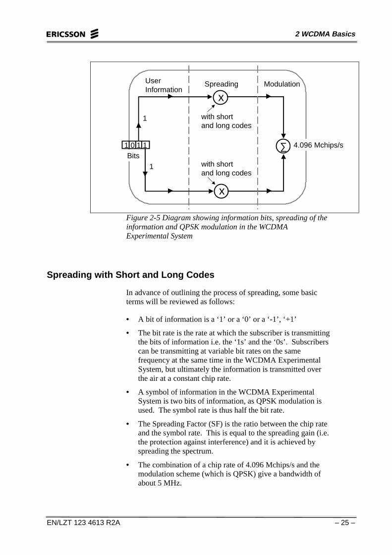
In the WCDMA Experimental System spreading is done aftersplitting the bits of information into two branches. The diagrambelow shows QPSK modulation of data. The spreading is the“multiplication” of the information by short and long codes andthis can be done simultaneously, or by the short code first andthen the long code. More details on spreading are given afterFigure 2-5 below.
2 WCDMA Basics
EN/LZT 123 4613 R2A – 25 –
x
∑
x
UserInformation
Spreading Modulation
with short and long codes
with short and long codes
1
1
Bits1 0 1 1 4.096 Mchips/s
Figure 2-5 Diagram showing information bits, spreading of theinformation and QPSK modulation in the WCDMAExperimental System
Spreading with Short and Long Codes
In advance of outlining the process of spreading, some basicterms will be reviewed as follows:
• A bit of information is a ‘1’ or a ‘0’ or a ‘-1’, ‘+1’
• The bit rate is the rate at which the subscriber is transmittingthe bits of information i.e. the ‘1s’ and the ‘0s’. Subscriberscan be transmitting at variable bit rates on the samefrequency at the same time in the WCDMA ExperimentalSystem, but ultimately the information is transmitted overthe air at a constant chip rate.
• A symbol of information in the WCDMA ExperimentalSystem is two bits of information, as QPSK modulation isused. The symbol rate is thus half the bit rate.
• The Spreading Factor (SF) is the ratio between the chip rateand the symbol rate. This is equal to the spreading gain (i.e.the protection against interference) and it is achieved byspreading the spectrum.
• The combination of a chip rate of 4.096 Mchips/s and themodulation scheme (which is QPSK) give a bandwidth ofabout 5 MHz.

WCDMA Experimental System Survey
– 26 – EN/LZT 123 4613 R2A
When information from various subscribers is sent over the airthis information can be sent at different bit rates depending onwhat service the subscriber is using at the time, that isspeech/video conferencing and so on.
1. If subscriber A transmits data at a symbol rate of 128 kspsthe Spreading Factor (SF) becomes 32.
2. If subscriber B is transmitting data at a bit rate of 64 ksps theSF becomes 64.
The following is valid for QPSK modulation:
SymbolRate*
Bit Rate ‘Multiply’by SF
ProcessingGain (dB)
Chip Rate
256 ksps 512 kbps 16 12 4.096Mchips/s
128 ksps 256 kbps 32 15 4.096Mchips/s
64 ksps 128 kbps 64 18 4.096Mchips/s
32 ksps 64 kbps 128 21 4.096Mchips/s
16 ksps 32 kbps 256 24 4.096Mchips/s
ksps =Kilosymbols per second
kbps=Kilobits per second
Mchips/s=Megachips per second
Note: In the example above 16 ksps is the lowest rateshown as this is the lowest symbol rate chosen for use inthe WCDMA Experimental System.
*Symbol Rate is 2 bits of information.

2 WCDMA Basics
EN/LZT 123 4613 R2A – 27 –
Short and Long Codes
Long codes are allocated in UL and DL from Gold sequences ofdifferent lengths. All BTSs and all MSs have unique longcodes.
The short codes are allocated from layered orthogonal Walshcodes. Each code is used to distinguish an individual channel.An allocation method is used that does not block codes in thecode tree unnecessarily. Depending on the SF used a certainWalsh code will be picked from the Walsh tree as seen in Figure2-6 below.
SF = 1 SF = 2 SF = 4
c1 = {1}
c2,1 = {1 1}
c2,2 = {1 -1}
c4,1 = {1 1 1 1}
c4,2 = {1 1 -1 -1}
c4,3 = {1 -1 1 -1}
c4,4 = {1 -1 -1 1}
Figure 2-6 Diagram showing Spreading Factor 1, 2 and 4 andhow the Walsh tree is built.
The primary function of the long codes in the WCDMAExperimental System is to distinguish between all BTSs and allMSs.
Good long codes should have low out-of –phase auto-correlation peaks to maximize the probability of correctsynchronization. The long codes should also have low cross-correlation peaks in order to minimize the interference betweendifferent BTSs and different MSs.
The short codes are used for channelization, i.e. to separatedifferent logical channels that are transmitted using the samelong code. These short codes are mutually orthogonal whichmeans that it is theoretically possible to separate the logicalchannels at the receiver. Unfortunately, due to multipathpropagation it is not possible to do this fully.
Figure 2-7 shows the generation of PN sequences (long codes).

WCDMA Experimental System Survey
– 28 – EN/LZT 123 4613 R2A
Modulus addition: 0 0=0, 0 1=1, 1 0=1, 1 1=0,+ + +
Maximum-length (ML) and Pseudo-noise (pn) shift-register sequences
10+ 0 00 0 1 1 1 1 0 1 0 1 1 00 1 00
+1 -1+1 +1+1 +1 -1 -1 -1 -1 +1 -1 +1 -1 -1 +1 +1 -1 +1 +1
• A shift register with n stages can assume (2 -1) states (excluding the "0" state)• A shift register with a suitable feedback passes all states and generates a periodic ML sequence with a period of 2n -1.
n
• Example: n=4
Modulus-2addition
Binary p-nsequence
Binary sequence
Bipolar sequence
1 2 3 4 5 6 7 8 9 10 11 12 13 14 15 16 17 18 19 20
Period= M=4 -1=152
• CharacteristicsBipolar ML sequence ("1"→ -1, "0" → +1) hasan autocorrelation function in the form of apulse train (see Fig. B1-2).This corresponds to an almost white spectrum.
The sequence contains a random train of "0"and "1"s.(e.g. Number of "1"s minus number of "0"s =1)(a) and b) explain the term "pseudo-noisesequence".)
a)
b)
+
Modulus-2 addition of two ML sequencesof the same classproduces another MLsequence of the same class.(Of the same class means from the sameshift registerarrangement but withdifferent starting states.)
c)
Figure 2-7 Generating binary maximum length PN sequences(long codes)
Long and short codes are combined in the WCDMAExperimental System and are thereafter used to spread the userdata. See Figure 2-5. The rate of both the long and short codegenerators is 4.096 Mchips/s while the rate of the data variesbetween 16 ksps and 256 ksps.
The short code generator is restarted after each data symbol (i.e.the period of the short code is always adapted to the user datarate) but the period of the long code generator is longer. Forexample on traffic channels DL, the long code is repeated everyradio frame (i.e. every 10 ms).
2 WCDMA Basics
EN/LZT 123 4613 R2A – 29 –
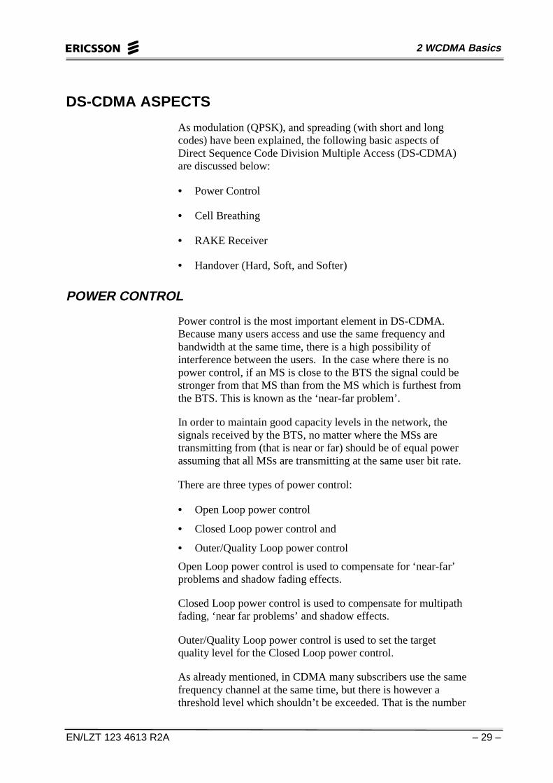
DS-CDMA ASPECTS
As modulation (QPSK), and spreading (with short and longcodes) have been explained, the following basic aspects ofDirect Sequence Code Division Multiple Access (DS-CDMA)are discussed below:
• Power Control
• Cell Breathing
• RAKE Receiver
• Handover (Hard, Soft, and Softer)
POWER CONTROL
Power control is the most important element in DS-CDMA.Because many users access and use the same frequency andbandwidth at the same time, there is a high possibility ofinterference between the users. In the case where there is nopower control, if an MS is close to the BTS the signal could bestronger from that MS than from the MS which is furthest fromthe BTS. This is known as the ‘near-far problem’.
In order to maintain good capacity levels in the network, thesignals received by the BTS, no matter where the MSs aretransmitting from (that is near or far) should be of equal powerassuming that all MSs are transmitting at the same user bit rate.
There are three types of power control:
• Open Loop power control
• Closed Loop power control and
• Outer/Quality Loop power control
Open Loop power control is used to compensate for ‘near-far’problems and shadow fading effects.
Closed Loop power control is used to compensate for multipathfading, ‘near far problems’ and shadow effects.
Outer/Quality Loop power control is used to set the targetquality level for the Closed Loop power control.
As already mentioned, in CDMA many subscribers use the samefrequency channel at the same time, but there is however athreshold level which shouldn’t be exceeded. That is the number
WCDMA Experimental System Survey
– 30 – EN/LZT 123 4613 R2A
of subscribers that can be added should not exceed a certainlevel. If this level is exceeded then other subscribers will beaffected by excessive interference. The threshold level isdecided and set by the operator. If the threshold level is veryhigh then the service quality offered to the subscriber will belower. What is required is a sufficiently high threshold level tomake efficient use of the network, but also a level which willprovide good service quality to the subscribers
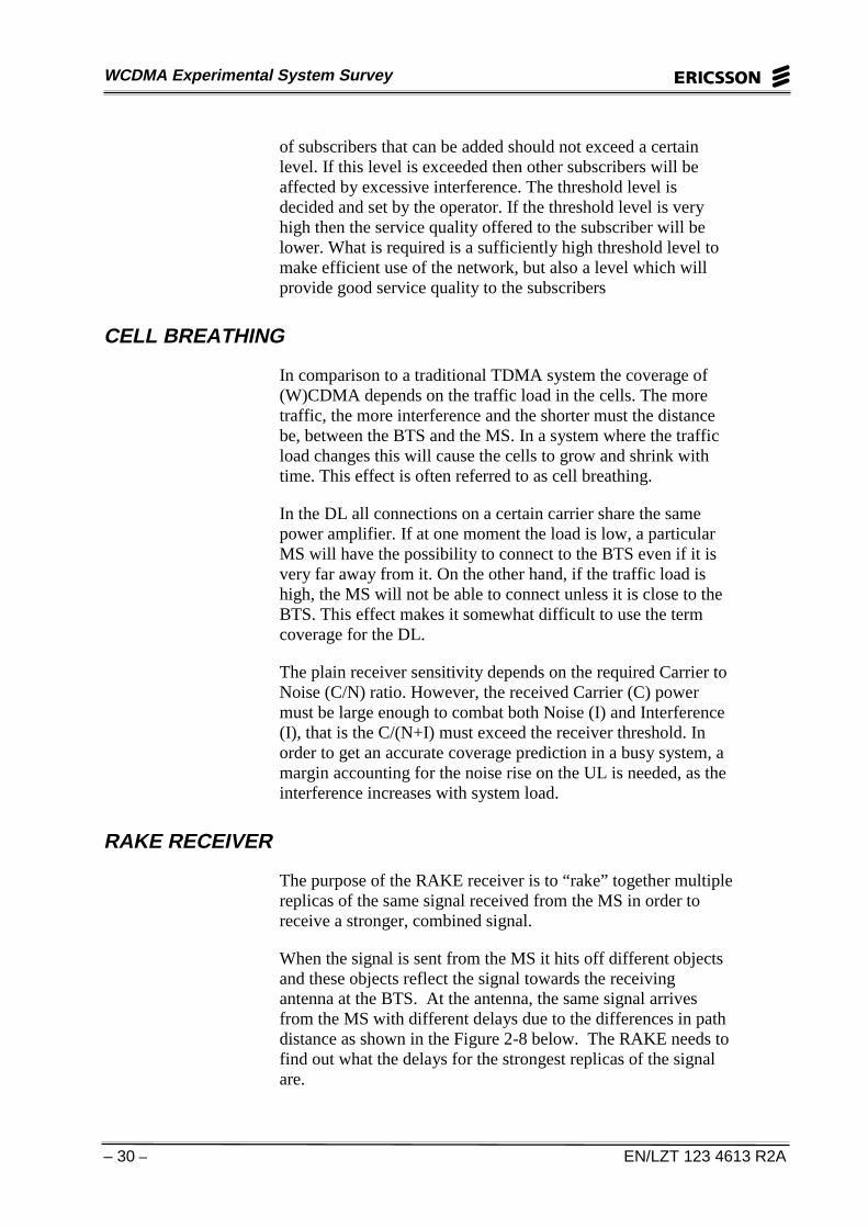
CELL BREATHING
In comparison to a traditional TDMA system the coverage of(W)CDMA depends on the traffic load in the cells. The moretraffic, the more interference and the shorter must the distancebe, between the BTS and the MS. In a system where the trafficload changes this will cause the cells to grow and shrink withtime. This effect is often referred to as cell breathing.
In the DL all connections on a certain carrier share the samepower amplifier. If at one moment the load is low, a particularMS will have the possibility to connect to the BTS even if it isvery far away from it. On the other hand, if the traffic load ishigh, the MS will not be able to connect unless it is close to theBTS. This effect makes it somewhat difficult to use the termcoverage for the DL.
The plain receiver sensitivity depends on the required Carrier toNoise (C/N) ratio. However, the received Carrier (C) powermust be large enough to combat both Noise (I) and Interference(I), that is the C/(N+I) must exceed the receiver threshold. Inorder to get an accurate coverage prediction in a busy system, amargin accounting for the noise rise on the UL is needed, as theinterference increases with system load.
RAKE RECEIVER
The purpose of the RAKE receiver is to “rake” together multiplereplicas of the same signal received from the MS in order toreceive a stronger, combined signal.
When the signal is sent from the MS it hits off different objectsand these objects reflect the signal towards the receivingantenna at the BTS. At the antenna, the same signal arrivesfrom the MS with different delays due to the differences in pathdistance as shown in the Figure 2-8 below. The RAKE needs tofind out what the delays for the strongest replicas of the signalare.

2 WCDMA Basics
EN/LZT 123 4613 R2A – 31 –
τ1 τ2 τ3 τ4 τ5
h(t)
Delay Power Spectrum
Figure 2-8 Multipath delays in the RAKE Receiver
The delays are then used to adjust the code sequence as seen inthe Figure 2-9.
Summation of allRAKE fingercontributors
τ1
τ2
τ3
Code SequenceGenerator
ThresholdDetector
Phase compensationof local oscillator
Weighting symbol.Depending on the
combining method, thistap has different values
AmplificationMultiplication symbol
Figure 2-9 RAKE Receiver with three fingers
HANDOVER (HARD, SOFT, SOFTER)
The main reasons for handover are connectivity and modechanges.
Due to the movements of the MS, radio links and connectionsneed to be changed from one or several sectors or BTSs toanother or several others, without dropping the call. Regardingmode changes, a change of a connection from a commonchannel to a dedicated channel and vice versa is required.
In soft handover an MS is connected to two or more BTSs at thesame time. In softer handover an MS is connected to two ormore sectors belonging to the same BTS.
WCDMA Experimental System Survey
– 32 – EN/LZT 123 4613 R2A
The purpose of soft and softer handover is to make use ofmacrodiversity. Macrodiversity is a powerful method ofcombating radio fading, and the soft/softer handover makes itpossible to take advantage of macrodiversity especially duringmobility.
The purpose of hard handover is the relocation of DL shortcodes(non-interrupted hard handover) or to realize a new active set oflogical sectors (re-synchronization hard handover). The mainreason for re-synchronization hard handover is to perform aninterfrequency handover.
Hard handover is for the relocation of DL short codes and forinterfrequency handover. Soft handover is for intrafrequencyhandover and softer handover is for intra frequency, intersectorhandover.

2 WCDMA Basics
EN/LZT 123 4613 R2A – 33 –
SUMMARY DESCRIPTION OF THE WCDMA EXPERIMENTALSYSTEM ACCESS TECHNIQUE
A summary of the WCDMA Experimental System accesstechnique is given below:
• A cell is a geographical area served by one BTS.
• The cell is further divided into sectors.
• A sector is a geographical area served by one sector antenna.
• The sector antenna is used for transmission and reception.
• In the WCDMA Experimental System the cell can bedivided into a maximum of six sectors.
• The spreading codes used are both short and long. A cell hasa cell specific long code. Sectors in the cell are separated byusing the long codes. Each physical channel in a specificsector has its own short code.
• The carrier symbol rate in the WCDMA ExperimentalSystem is 16, 32, 64, 128 or 256 ksymbols per second.
• One modulated symbol in the WCDMA ExperimentalSystem is 2 bits of information.
• The modulation method used is QPSK.
• The main reasons for handover are connectivity and modechanges.
• The access method used in the Experimental System is –DS-CDMA with a chiprate of 4.096 Mchips/sec.

WCDMA Experimental System Survey
– 34 – EN/LZT 123 4613 R2A
ll aa nn kkBB
iioonnaall llyy
ttnneettnnII