
WaveRunner Oscilloscope Remote Control Manual - Teledyne LeCroy
286
R R EMOTE C C ONTROL M M ANUAL J ANUARY 2002
Transcript of WaveRunner Oscilloscope Remote Control Manual - Teledyne LeCroy

RR EE MM OO TT EE CC OO NN TT RR OO LL MM AA NN UUAA LL
JJAA NN UUAA RRYY 22 00 0022

LeCroy Corporation 700 Chestnut Ridge Road Chestnut Ridge, NY 10977–6499 Tel: (845) 578 6020, Fax: (845) 578 5985
Internet: www.lecroy.com
© 2002 by LeCroy Corporation. All rights reserved. Information in this publication supersedes all earlier versions. Specifications subject to change.
LeCroy, ProBus and SMART Trigger are registered trademarks, and ActiveDSO, ScopeExplorer, WaveAnalyzer and Waverunner are trademarks, of LeCroy Corporation. Centronics is a registered trademark of Data Computer Corp. Epson is a registered trademark of Epson America Inc. Mathcad is a registered trademark of MATHSOFT Inc. MATLAB is a registered trademark of The MathWorks, Inc. Microsoft, MS and Microsoft Access are registered trademarks, and Windows and NT trademarks, of Microsoft Corporation. PowerPC is a registered trademark of IBM Microelectronics. DeskJet, ThinkJet, QuietJet, LaserJet, PaintJet, HP 7470 and HP 7550 are registered trademarks of Hewlett-Packard Company.
Manufactured under an ISO 9000 Registered Quality Management System
Visit www.lecroy.com to view the certificate.
This electronic product is subject to disposal and recycling regulations that vary by country and region. Many countries prohibit the disposal of waste electronic equipment in standard waste receptacles.
For more information about proper disposal and recycling of your LeCroy product, please visit www.lecroy.com/recycle.
LTXXX-RCM-E Rev B

LTXXX-RCM-E Rev B ISSUED: January 2002 iii
T A B L E O F C O N T E N T S
INTRODUCTION ........................................................................................................1
PPAARRTT OONN EE :: AABBOOUUTT RREE MMOOTTEE CCOONN TTRROOLL ............... 3
CHAPTER ONE: OVERVIEW....................................................................................5
Operate Waverunner by Remote Control......................................................................................... 5STANDARDS............................................................................................................................................................6PROGRAM MESSAGES ........................................................................................................................................6COMMANDS AND QUERIES............................................................................................................................7HEADERS .................................................................................................................................................................8HEADER PATHS.....................................................................................................................................................8DATA...........................................................................................................................................................................9CHARACTER DATA ..............................................................................................................................................9NUMERIC DATA ....................................................................................................................................................9STRING DATA.......................................................................................................................................................10BLOCK DATA........................................................................................................................................................10RESPONSE MESSAGES .....................................................................................................................................10USE SCOPEEXPLORER ...........................................................................................................................................11
CHAPTER TWO: CONTROL BY GPIB ................................................................... 13
Talk, Listen or Control....................................................................................................................13TALK, LISTEN OR CONTROL ........................................................................................................................13INTERFACE............................................................................................................................................................13ADDRESS ................................................................................................................................................................14GPIB SIGNALS......................................................................................................................................................14I/O BUFFERS.........................................................................................................................................................14USE IEEE 488.1 STANDARD MESSAGES ...................................................................................................15DEVICE CLEAR....................................................................................................................................................15GROUP EXECUTE TRIGGER.........................................................................................................................15REMOTE ENABLE ..............................................................................................................................................15INTERFACE CLEAR............................................................................................................................................16CONFIGURE THE GPIB-DRIVER SOFTWARE .......................................................................................16MAKE SIMPLE TRANSFERS............................................................................................................................17USE ADDITIONAL DRIVER CALLS.............................................................................................................19MAKE SERVICE REQUESTS ...........................................................................................................................19
Take Instrument Polls ....................................................................................................................21DO CONTINUOUS POLLING ........................................................................................................................21TAKE A SERIAL POLL .......................................................................................................................................21DO A PARALLEL POLL .....................................................................................................................................22

T A B L E O F C O N T E N T S
iv ISSUED: January 2002 LTXXX-RCM-E Rev B
PERFORM AN *IST POLL ..............................................................................................................................24Drive Hard-copy Devices on the GPIB ..........................................................................................25
READ DATA BY CONTROLLER....................................................................................................................25SEND DATA TO BOTH .....................................................................................................................................25TALK DIRECTLY TO PRINTER.....................................................................................................................26
CHAPTER THREE: CONTROL BY RS232............................................................. 29
Communicate through the RS-232-C Port .....................................................................................29HANDSHAKE CONTROL ................................................................................................................................29EDITING FEATURES.........................................................................................................................................30MESSAGE TERMINATORS..............................................................................................................................30SRQ MESSAGE ......................................................................................................................................................31LONG LINE SPLITTING ..................................................................................................................................31REMARKS...............................................................................................................................................................32
Simulate GPIB Messages...............................................................................................................33
CHAPTER FOUR: UNDERSTAND AND MANAGE WAVEFORMS ................... 35
Know Your Waveform.....................................................................................................................35LOGICAL DATA BLOCKS................................................................................................................................35INSPECT WAVEFORM CONTENTS .............................................................................................................36USE THE WAVEFORM QUERY......................................................................................................................37INTERPRET VERTICAL DATA ......................................................................................................................39CALCULATE A DATA POINT’S HORIZONTAL POSITION ...............................................................40USE THE WAVEFORM COMMAND.............................................................................................................42
Transfer Waveforms at High Speed................................................................................................43
CHAPTER FIVE: CHECK WAVEFORM STATUS ................................................. 45
Use Status Registers.......................................................................................................................45OVERVIEW............................................................................................................................................................45STATUS BYTE REGISTER (STB)....................................................................................................................47STANDARD EVENT STATUS REGISTER (ESR) ......................................................................................47STANDARD EVENT STATUS ENABLE REGISTER (ESE)...................................................................48SERVICE REQUEST ENABLE REGISTER (SRE).....................................................................................48PARALLEL POLL ENABLE REGISTER (PRE)..........................................................................................48INTERNAL STATE CHANGE STATUS REGISTER (INR).....................................................................48INTERNAL STATE CHANGE ENABLE REGISTER (INE) ..................................................................49COMMAND ERROR STATUS REGISTER (CMR).....................................................................................49DEVICE DEPENDENT ERROR STATUS REGISTER (DDR)..............................................................49EXECUTION ERROR STATUS REGISTER (EXR)...................................................................................49USER REQUEST STATUS REGISTER (URR) .............................................................................................49
T A B L E O F C O N T E N T S
LTXXX-RCM-E Rev B ISSUED: January 2002 v
PPAARRTT TTWWOO:: CCOOMMMMAANN DDSS .......................................... 53Use Waverunner Commands and Queries..................................................................................... 53
COMMAND NOTATION...................................................................................................................................53Table of Commands and Queries – By Short Form... ................................................................... 55Table of Commands and Queries – By Subsystem... .................................................................... 59
APPENDIX I, GPIB PROGRAM EXAMPLES ....................................................... 255
Example 1.....................................................................................................................................255USE THE INTERACTIVE GPIB PROGRAM “IBIC” ..............................................................................255
Example 2.....................................................................................................................................256USE THE GPIB PROGRAM FOR IBM PC (HIGH-LEVEL FUNCTION CALLS)..........................256
Example 3.....................................................................................................................................260USE GPIB PROGRAM FOR IBM PC (LOW-LEVELFUNCTION CALLS)........................................260
APPENDIX II, WAVEFORM TEMPLATE ............................................................ 263
Waveform Template......................................................................................................................263
INDEX....................................................................................................................... 275

vi ISSUED: January 2002 LTXXX-RCM-E Rev B
BLANK PAGE

LTXXX-RCM-E Rev B ISSUED: January 2002 1
I N T R O D U C T I O N
About this Manual
This manual explains howto remotely control the oscilloscope, using commands keyed into the externalcontroller. This controller will normally be a computer, although it could be a simple terminal.
The manual includes a complete list of the commands you’ll need to perform most Waverunner operations(you can find commands for a fewspecial, optional functions in the software option’s dedicated manual). Themanual has two main parts:
Part One, “About Remote Control,” covers the principles of remote control, and offers practicalexamples.
Part Two, “Commands,” describes each of the remote control commands and queries for Waverunneroperations. It starts with two special indexes that list the commands by short name and by category. Use theseto find the command or query you wish to use.
See also the table of contents and the index at the back of the manual.
As an additional guide, each chapter is prefaced by a summary of its contents.
Watch for these icons and the information they signal:
TTIIPPss offer additional hints on howto get the most out of Waverunner actions or features.
NNOOTTEEss bring to your attention important information you should know.
See also Chapter 12, “Use Waverunner with PC,” in the Operator’s Manual.

2 ISSUED: January 2002 LTXXX-RCM-E Rev B
BLANK PAGE

LTXXX-RCM-E Rev B ISSUED: January 2002 3
PPAARRTT OONN EE
AA BB OO UU TT
RR EE MM OO TT EE CC OO NN TT RR OO LLPart One of the manual explains how Waverunner operates under remote control. It covers GPIB andRS-232-C interfaces, the transfer and formatting of waveforms, and the use of status bytes in reportingerrors.

4 ISSUED: January 2002 LTXXX-RCM-E Rev B
C H A P T E R O N E : Overview
In this chapter, see how
To construct program messages
To use commands and queries
To include data, and make data strings
To use ScopeExplorer for remote control

LT3XX-RCM-E Rev B ISSUED: January 2002 5
C H A P T E R O N E Overview
Operate WaverunnerbyRemoteControlYou can fully control your Waverunner oscilloscope remotely by using either the GPIB (General PurposeInterface Bus) port or the RS-232-C communication port on the scope rear panel, shown below. The onlyactions for which you must use the front panel controls are the powering up of the scope and the setting ofremote addresses. Use LeCroy’s ScopeExplorer software as the ideal interface between scope and PC (see page11).
RS-232-C Port GPIB PortCentronics Port
Power InputBN C Signal Output
External Monitor Port PC Card Slot(Memory/Hard-Disk card )
Waverunner back panel, including the GPIB and R S -232-C ports used in remote control.
TTIIPP:: Use Waverunner Remote Control Assistant to monitor all your remote control operations. See theCOMM_HELP command in Part Two of this manual, and Chapter 12 of the Operator’s Manual, “UseWaverunner with PC”.

P A R T O N E : A B O U T R E M O T E C O N T R O L
6 ISSUED: January 2002 LTXXX-RCM-E Rev B
STANDARDS
LeCroy remote control commands conform to the GPIB IEEE 488.2* standard. This may be considered anextension of the IEEE 488.1 standard, which deals mainly with electrical and mechanical issues. The IEEE488.2 recommendations have also been adopted for RS-232-C communications wherever appropriate.
PROGRAM MESSAGES
You control the oscilloscope remotely using program messages that consist of one or several commands orqueries. The program messages you send from the external controller to the Waverunner oscilloscope mustconform to precise format structures. The oscilloscope will execute all program messages sent in the correctform, but will ignore those with errors.
You can use upper- or lower-case characters, or both, in program messages.
Warning or error messages are normally not reported unless the controller explicitly examines the relevant statusregister, or if the status-enable registers have been set so that the controller can be interrupted when an erroroccurs. If you connect an external monitor to the Waverunner’s RS-232-C port, however, you will be able toobserve all your remote control transactions, including error messages, as they happen. See the commandCOMM_HELP in Part Two, “Commands.”
Program messages are separated by semicolons ; and end in a terminator:<command/query>;.........;<command/query> <terminator> .
The oscilloscope will not decode an incoming program message before receiving its terminator. The exception iswhen the program message is longer than the 256 byte input buffer; then the oscilloscope will start analyzing themessage when the buffer is full. Commands and queries are executed in the order in which they are transmitted.
In GPIB mode, the following are valid terminators:
<NL> New-line character (i.e. the ASCII new-line character, whose decimal value is 10).
<NL><EOI> New-line character with a simultaneous <EOI> signal.
<EOI><EOI> Signal together with the last character of the program message.
The <NL> <EOI> terminator is always used in response messages sent by the oscilloscope to the controller.
In RS-232-C communications, you can define the terminator with the command COMM_RS232. The defaultvalue is <CR>, which is the ASCII carriage return character, whose decimal value is 13.
NN OOTTEE :: The <EOI> signal is a dedicated GPIB interface line, which canbe set with a special call to the GPIB interface driver. Refer to the GPIBinterface manufacturer’s manual and support programs.
*ANSI/IEEE Std. 488.2–1987, IEEE Standard Codes, Formats, Protocols, and Common Commands. The Institute of Electrical and Electronics EngineersInc., 345 East 47th Street, NewYork, NY 10017 USA.

C H A P T E R O N E : Overview
LT3XX-RCM-E Rev B ISSUED: January 2002 7
COMMANDS AND QUERIES
Program messages are made up of one or more commands or queries. While the command directs theoscilloscope to change its state (for example, its timebase or vertical sensitivity) the query asks the oscilloscopeabout that state. Very often, you will use the same mnemonic for a command and a query, the query beingidentified by a ? after the last character.
For example, to change the timebase to 2 ms/div, send this command to the oscilloscope:TIME_DIV 2 M
Or, to ask the oscilloscope about its timebase, send this query:TIME_DIV?
A query causes the oscilloscope to send a response message. The control program should read this message witha ‘read’ instruction to the GPIB or RS-232-C interface of the controller.
The response message to the above query might be:TIME_DIV 10 NS
The portion of the query preceding the question mark is repeated as part of the response message. If desired,this text can be suppressed with the command COMM_HEADER.
Depending on the state of the oscilloscope and the computation to be done, several seconds may pass before aresponse is received. Command interpretation does not have priority over other oscilloscope activities.
The general form of a command or a query consists of a command header, <header>, optionally followed byone or several parameters, <data>, separated by commas:
<header>[?] <data>,...,<data>
The notation [?] shows that the question mark is optional (turning the command into a query).
There is a space between the header and the first parameter.
There are commas between parameters.
The following are examples of howprogrammessages are made up of commands and queries...
GRID DUAL: This program message consists of asingle command that instructs the oscilloscope todisplay a dual grid.
TTIIPP:: Set the controller I/O timeout conditionsto three or more seconds to give the scope timeto respond. An incorrect query will not get aresponse; and, if Remote Control Assistant isenabled, a beep will sound.
The terminator is not shown, as it is usually automatically added by the interface driver routine writing to GPIBor RS232.
DZOM ON; DISPLAY OFF; DATE?:This program message consists of two commands, followed by aquery. They instruct the oscilloscope to turn on the multi-zoom mode, turn off the display, and then ask for thecurrent date. Again, the terminator is not shown.
DATE 15,JAN,1993,13,21,16: This command instructs the oscilloscope to set its date and time to 15JAN 1993, 13:21:16. The command header DATE indicates the action, the 6 data values specify it in detail.

P A R T O N E : A B O U T R E M O T E C O N T R O L
8 ISSUED: January 2002 LTXXX-RCM-E Rev B
HEADERS
The header is the mnemonic form of the operation to be performed by the oscilloscope. Most command andquery headers have a long form, which allows them to be read more easily, and a short form for better transferand decoding speed. The two are fully equivalent and you can use them interchangeably. For example,TRIG_MODE AUTO and TRMD AUTO are two separate but equivalent commands for switching to theautomatic trigger mode.
Some command or query mnemonics are imposed by the IEEE 488.2 standard. They are standardized so thatdifferent oscilloscopes will present the same programming interface for similar functions. All these mnemonicsbegin with an asterisk * . For example, the command *RST is the IEEE 488.2 imposed mnemonic for resettingthe oscilloscope, whereas *TST? instructs the oscilloscope to perform an internal self-test and report theoutcome.
HEADER PATHS
Certain commands or queries apply to a sub-section of the oscilloscope; for example, a single input channel or atrace on the display. In such cases, you must prefix the header by a path name that indicates the channel or traceto which the command applies. The header path normally consists of a two-letter path name followed by acolon : immediately preceding the command header. One of the waveform traces can usually be specified in theheader path:
H E AD E R PAT H N AM E WAV E F O R M T R AC E
C1, C2 Channels 1 and 2
C3, C4 Channels 3 and 4 (on four-channel models)
M1, M2, M3, M4 Memories 1, 2, and 3 and 4
TA, TB, TC, TD Traces A, B, C and D
EX, EX10, EX5 External trigger
LINE LINE source for trigger
Example: C1:OFST -300 MV Command to set the offset of Channel 1 to −300 mV.
You need only specify a header path once. Subsequent commands with header destinations not indicated areassumed to refer to the last defined path. For example, the queries C2:VDIV?; C2:OFST? ask: What is thevertical sensitivity and the offset of channel 2? While the queries C2:VDIV?; OFST? ask exactly the samequestion without repeating the path.

C H A P T E R O N E : Overview
LT3XX-RCM-E Rev B ISSUED: January 2002 9
DATA
Whenever a command or query uses additional data values, the values are expressed as ASCII characters. Thereis a single exception: the transfer of waveforms with the command/queryWAVEFORM, where the waveform canbe expressed as a sequence of binary data values. See Chapter 4, “Waveform Structure.” ASCII data canhave the form of character, numeric, string, or block data.
CHARACTER DATA
These are simple words or abbreviations to indicate a specific action.
Example: DUAL_ZOOM ON
In this example, the data valueON commands the dual zoom mode to be turned on (the data valueOFF willhave the opposite effect).
However, this can become more complex. In some commands, where you can specify as many as a dozendifferent parameters, or where not all the parameters are applicable at the same time, the format requires pairs ofdata values. The first value names the parameter to be modified, while the second gives its value. Only thoseparameter pairs changed need to be indicated.
Example: HARDCOPY_SETUP DEV,EPSON,PORT,GPIB
In this example, two pairs of parameters have been used. The first specifies the device as an EPSON (orcompatible) printer, while the second indicates the GPIB port. While the command HARDCOPY_SETUP allowsmany more parameters, either they are not relevant for printers or they are left unchanged.
NUMERIC DATA
The numeric data type is used to enter quantitative information. Numbers can be entered as integers orfractions, or in exponential representation:
TA:VPOS -5 Move the displayed trace of Trace A downwards by five divisions.C2:OFST 3.56 Set the DC offset of Channel 2 to 3.56 V.TDIV 5.0E-6 Adjust the timebase to 5 µsec/div.
Example: There are many ways of setting the timebase of the oscilloscope to 5 µsec/div:
TDIV 5E-6 Exponential notation, without any suffix.TDIV 5 US Suffix multiplier U for 1E−6, with the (optional) suffix S for seconds.orTDIV 5000 NSTDIV 5000E-3 US
You can follownumeric values with multipliers and units, to modify the value of the numerical expression. Thefollowing mnemonics are recognized:

P A R T O N E : A B O U T R E M O T E C O N T R O L
10 ISSUED: January 2002 LTXXX-RCM-E Rev B
M U L T I PL I E R E XP. N O T E . SU F F I X M U L T I PL I E R E XP. N O T E . SU F F I X
EX 1E18 Exa- PE 1E15 Peta-
T 1E12 Tera- G 1E9 Giga-
MA 1E6 Mega- K 1E3 kilo-
M 1E−3 milli- U 1E−6 micro-
N 1E−9 nano- PI 1E−12 pico-
F 1E−15 femto- A 1E−18 atto-
STRING DATA
This data type enables you to transfer a (long) string of characters as a single parameter. Simply enclose anysequence of ASCII characters between single or double quotation marks:
MESSAGE ‘Connect probe to point J3’
The oscilloscope displays this message in the Message field above the grid.
BLOCK DATA
These are binary data values coded in hexadecimal ASCII: four-bit nibbles translated into the digits 0 through 9or A through F, and transmitted as ASCII characters. They are used only for the transfer of waveforms fromWaverunner to controller (WAVEFORM) and for Waverunner panel setups (PANEL_SETUP)
RESPONSE MESSAGES
The oscilloscope sends a response message to the controller in answer to a query. The format of such messagesis the same as that of program messages: individual responses in the format of commands, separated bysemicolons ; and ending in terminators. These messages can be sent back to the oscilloscope in the form inwhich they were received, to be accepted as valid commands. In GPIB response messages, the <NL> <EOI>terminator is always used.
Example: The controller sends the program message:TIME_DIV?;TRIG_MODE NORM;C1:COUPLING? (terminator not shown).
The oscilloscope might respond to this with:TIME_DIV 50 NS;C1:COUPLING D50 (terminator not shown).
The response message refers only to the queries: TRIG_MODE is left out. If this response is sent back to theoscilloscope, it is a valid program message for setting its timebase to 50 ns/div and the input coupling ofChannel 1 to 50 Ω.
Whenever you expect a response from the oscilloscope, you must have the control program instruct the GPIBor RS-232-C interface to read from the oscilloscope. If the controller sends another program message withoutreading the response to the previous one, the response message in the output buffer of the oscilloscope will be

C H A P T E R O N E : Overview
LT3XX-RCM-E Rev B ISSUED: January 2002 11
discarded. The oscilloscope keeps to stricter rules for response messages than for acceptance of programmessages. While you can send program messages from the controller in upper- or lower-case characters,response messages are always returned in upper-case. Program messages may contain extraneous spaces or tabs(white space), but response messages will not. And while program messages may contain a mixture of short andlong command or query headers, response messages always use short headers by default.
However, you can use the command COMM_HEADER to force the oscilloscope to use long headers, or none atall. If the response header is omitted, the response transfer time will be minimized. But the response will not beable to be sent back to the oscilloscope. Suffix units are also suppressed in the response.
If you were to set the trigger slope of Channel 1 to negative, the queryC1:TRSL? might yield the followingresponses:
C1:TRIG_SLOPE NEG header format: long
C1:TRSL NEG header format: short
NEG header format: off
TTIIPP:: Waveforms you obtain from theoscilloscope using the queryWAVEFORM? area special kind of response message. Controltheir exact format by using theCOMM_FORMAT and COMM_ORDERcommands.
USE SCOPEEXPLORER
ScopeExplorer is an easy-to-use and practical software tool for interfacing your Waverunner oscilloscope with aPC running Windows:
1. Connect the scope to a PC using either the GPIB (you’ll need a PC with GPIB card installed) or PC-standard RS-232-C port on the scope’s rear panel.
2. Download ScopeExplorer free of charge at http://www.lecroy.com/scopeexplorer. Or inquire at yourLeCroy customer service center.
3. Having installed ScopeExplorer, open it as you would any Windows program. Use its on-line help to do thefollowing:
Use the teletype-like terminal to send standard remote control commands from computer tooscilloscope, and to display the Waverunner response on the PC.
Control the scope by means of an interactive, virtual scope front panel.
Pipe sequences of commands from a file to the scope, then send the scope’s responses to another file.
Transfer pixel-for-pixel copies of your Waverunner display to PC, then view them, print them, or bothfrom the computer. With a single press of a button or key, you can copy bitmap waveform images tothe Windows Clipboard, ready to paste into any Windows application.
Capture Waverunner front panel setups and, using a long filename, store them on the computer. Youcan then transfer them back into the scope to reproduce an identical setup.
Transfer your waveforms to PC, and store them in either the compact LeCroy Binary format, or anASCII version compatible with PC-based analysis products.

12 ISSUED: January 2002 LTXXX-RCM-E Rev B
C H A P T E R T W O : Control byGPIB
In this chapter, see how
To address your Waverunner scope for GPIB
To configure GPIB software
To enable remote or local control
To make transfers of data
To make service requests
To poll Waverunner
To drive hardcopy devices

LTXXX-RCM-E Rev B ISSUED: January 2002 13
C H A P T E R T W O Control byGPIB
Talk, Listen, orControl
You can remotely control your Waverunner oscilloscope, using the General Purpose Interface Bus (GPIB).GPIB is similar to a standard computer bus. But while the computer interconnects circuit cards by means of abackplane bus, the GPIB interconnects independent devices (oscilloscopes and computers, for example) bymeans of a cable bus. GPIB also carries both program and interface messages.
Program messages, often called device dependent messages, contain programming instructions, measurementresults, and oscilloscope status and waveform data.
Interface messages manage the bus itself. They perform functions such as initialization, addressing and“unaddressing” of devices, and the setting of remote and local modes.
TALK, LISTEN, OR CONTROL
On the one hand, devices connected by GPIB to your Waverunner oscilloscope can be listeners, talkers, orcontrollers. A talker sends program messages to one or more listeners, while a controller manages the flowofinformation on the bus by sending interface messages to the devices. The host computer must be able to playall three roles. For details of how the controller configures the GPIB for specific functions, refer to the GPIBinterface manufacturer’s manual.
On the other hand, the Waverunner can be a talker or listener, but NOT a controller.
INTERFACE
Waverunner interface capabilities include the following IEEE 488.1 definitions:
AH1 Complete Acceptor Handshake DC1 Complete Device Clear Function
SH1 Complete Source Handshake DT1 Complete Device Trigger
L4 Partial Listener Function PP1 Parallel Polling: remote configurable
T5 Complete Talker Function C0 No Controller Functions
SR1 Complete Service Request Function E2 Tri-state Drivers
RL1 Complete Remote/Local Function

P A R T O N E : A B O U T R E M O T E C O N T R O L
14 ISSUED: January 2002 LTXXX-RCM-E Rev B
ADDRESS
Every device on the GPIB has an address. To address Waverunner, set the remote control port to GPIB bymeans of the scope’s front panel UTILITIES button and on-screen menus. If you select “RS-232” in the sameway, the oscilloscope will execute over the GPIB solely “talk-only” operations, such as driving a printer. SettingWaverunner to “RS-232” enables the oscilloscope to be controlled through the RS-232-C port. See Chapter 12of the Operator’s Manual for howto do this.
If you address Waverunner to talk, it will remain in that state until it receives a universal untalk command(UNT), its own listen address (MLA), or another oscilloscope’s talk address.
If you address Waverunner to listen, it will remain configured to listen until a universal unlisten command(UNL), or its own talker address (MTA), is received.
GPIB SIGNALS
The GPIB bus system consists of 16 signal lines and eight ground or shield lines. The signal lines are dividedinto three groups:
Data Lines: These eight lines, usually called DI01 through DI08, carry both program and interface messages.Most of the messages use the 7-bit ASCII code, in which case DI08 is unused.
Handshake Lines: These three lines control the transfer of message bytes between devices. The process iscalled a three-wire interlocked handshake, and it guarantees that the message bytes on the data lines are sentand received without transmission error.
Interface Management Lines: These five lines manage the flowof information across the interface:
ATN (ATteNtion): The controller drives the ATN line true when it uses the data lines to send interfacemessages such as talk and listen addresses or a device clear (DCL) message. When ATN is false, the bus is indata mode for the transfer of program messages from talkers to listeners.
IFC (InterFace Clear): The controller sets the IFC line true to initialize the bus.
REN (Remote ENable): The controller uses this line to place devices in remote or local program mode.
SRQ (Service ReQuest): Any device can drive the SRQ line true to asynchronously request service from thecontroller. This is the equivalent of a single interrupt line on a computer bus.
EOI (End Or Identify): This line has two purposes: The talker uses it to mark the end of a message string.The controller uses it to tell devices to identify their response in a parallel poll (discussed later in this section).
I/O BUFFERS
The oscilloscope has 256-byte input and output buffers. An incoming program message is not decoded beforea message terminator has been received. However, if the input buffer becomes full (because the programmessage is longer than the buffer), the oscilloscope starts analyzing the message. In this case data transmissionis temporarily halted, and the controller may generate a timeout if the limit was set too low.

C H A P T E R T W O : Control byGPIB
LTXXX-RCM-E Rev B ISSUED: January 2002 15
USE IEEE 488.1STANDARD MESSAGES
The IEEE 488.1 standard specifies not only the mechanical and electrical aspects of the GPIB, but also thelow-level transfer protocol. For instance, it defines howa controller addresses devices, turns them into talkersor listeners, resets them or puts them in the remote state. Such interface messages are executed with theinterface management lines of the GPIB, usually with ATN true.
All these messages except GET are executedimmediately upon receipt.
The command list in Part Two of this manual doesnot contain a command for clearing the input oroutput buffers, nor for setting the oscilloscope to theremote state.
NOTE: In addition to the IEEE 488.1interfacemessage standards, the IEEE 488.2 standardspecifies certain standardized program messages,i.e., command headers. They are identified with aleading asterisk * and are listed in the SystemCommands section.
This is because such commands are already specified as IEEE 488.1 standard messages. Refer to the GPIBinterface manual of the host controller as well as to its support programs, which should contain special calls forthe execution of these messages.
The following description covers those IEEE 488.1 standard messages that go beyond mere reconfiguration ofthe bus and that have an effect on Waverunner operation.
DEVICE CLEAR
In response to a universal Device CLear (DCL) or a Selected Device Clear message (SDC), Waverunner clearsthe input or output buffers, cancels the interpretation of the current command (if any) and clears pendingcommands. However, status registers and status-enable registers are not cleared. Although DCL will have animmediate effect, it can take several seconds to execute if the oscilloscope is busy.
GROUP EXECUTE TRIGGER
The Group Execute Trigger message (GET) causes Waverunner to arm the trigger system, and is functionallyidentical to the*TRG command.
REMOTE ENABLE
This interface message is executed when the controller holds the Remote ENable control line (REN) true,allowing you to configure the oscilloscope as a listener. All the front panel controls except the menu buttonsare disabled. The menu indications on the right-hand side of the screen no longer appear, since menus cannotnowbe operated manually. Instead, the text REMOTE ENABLE appears at the top of the menu field toindicate that the oscilloscope is set in the remote mode. Whenever the controller returns the REN line to false,all oscilloscopes on the bus return to GO TO LOCAL.
When you press the GO TO LOCAL menu button, the scope returns to front panel control, unless you haveplaced the oscilloscope in Local LOckout (LLO) mode (see below).

P A R T O N E : A B O U T R E M O T E C O N T R O L
16 ISSUED: January 2002 LTXXX-RCM-E Rev B
The Go To Local message (GTL) causes the oscilloscope to return to local mode. All front panel controlsbecome active and the normal menus reappear. Thereafter, whenever the oscilloscope is addressed as a listenerit will be immediately reset to the remote state, except when the LLO command has been sent.
When you activate Local Lockout the scope can only be returned to its local state by returning the LLO tofalse. Whenever you return the oscilloscope to the remote state the local lockout mode will immediatelybecome effective again.
The Local LOckout message (LLO) causes the GO TO LOCAL menu to disappear. You can send this messagein local or remote mode. But it only becomes effective once you have set the oscilloscope in remote mode.
INTERFACE CLEAR
The InterFace Clear message (IFC) initializes the GPIB but has no effect on the operation of the Waverunner.
NN OOTTEE :: To illustrate the GPIB programming concepts a number of examples written in BASICA areincluded here. It is assumed that the controller is IBM-PC compatible, running under DOS, and thatit is equipped with a National Instruments GPIB interface card. Nevertheless, GPIB programmingwith other languages such as C or Pascal is quite similar. If you’re using another type of computer orGPIB interface, refer to the interface manual for installation procedures and subroutine calls.
CONFIGURE THE GPIB DRIVER SOFTWARE
1. Verify that the GPIB interface is properly installed in the computer. If it is not, follow the interfacemanufacturer’s installation instructions. In the case of the National Instruments interface, it is possible tomodify the base I/O address of the board, the DMA channel number, and the interrupt line setting usingswitches and jumpers. In the program examples below, default positions are assumed.
2. Connect Waverunner to the computer with a GPIB interface cable.
3. Set the GPIB address to the required value. The program examples assume a setting of 4.
The host computer requires an interface driver that handles the transactions between the operator’s programsand the interface board.
In the case of the National Instruments interface, the installation procedure will:
a. Copy the GPIB handler GPIB.COM into the boot directory.
b. Modify the DOS system configuration file CONFIG.SYS to declare the presence of the GPIB handler.
c. Create a sub-directory called GPIB-PC, and install in GPIB-PC a number of files and programs useful fortesting and reconfiguring the system, and for writing user programs.
The following files in the sub-directory GPIB-PC are particularly useful:
IBIC.EXE allows interactive control of the GPIB by means of functions entered at the keyboard. Use of thisprogram is highly recommended to anyone unfamiliar with GPIB programming or with Waverunner’s remotecommands.

C H A P T E R T W O : Control byGPIB
LTXXX-RCM-E Rev B ISSUED: January 2002 17
DECL.BAS is a declaration file that contains code to be included at the beginning of any BASICA applicationprogram. Simple application programs can be quickly written by appending the operator’s instructions toDECL.BAS and executing the complete file.
IBCONF.EXE is an interactive program that allows inspection or modification of the current settings of theGPIB handler. To run IBCONF.EXE, refer to the National Instruments manual.
NN OOTTEE :: In the program examples in this section, it is assumed that the National Instruments GPIBdriver GPIB.COM is in its default state, i.e., that the user has not modified it with IBCONF.EXE.This means that the interface board can be referred to by the symbolic name ‘GPIB0’ and that deviceson the GPIB bus with addresses between 1and 16 can be called by the symbolic names ‘DEV1’ to‘DEV16’. If you have a National Instruments PC2 interface card rather than PC2A, you must runIBCONF to declare the presence of this card rather than the default PC2A.
MAKE SIMPLE TRANSFERS
For a large number of remote control operations it is sufficient to use just three different subroutines(IBFIND, IBRD and IBWRT) provided by National Instruments. The following complete program reads thetimebase setting of Waverunner and displays it on the terminal:
1–99 <DECL.BAS>
100 DEV$=“DEV4”
110 CALL IBFIND(DEV$,SCOPE%)
120 CMD$=“TDIV?”
130 CALL IBWRT(SCOPE%,CMD$)
140 CALL IBRD(SCOPE%,RD$)
150 PRINT RD$
160 END
Lines 1–99 are a copy of the file DECL.BAS supplied by National Instruments. The first six lines are requiredfor the initialization of the GPIB handler. The other lines are declarations which may be useful for largerprograms, but are not really required code. The sample program above only uses the strings CMD$ and RD$,which are declared in DECL.BAS as arrays of 255 characters.
Lines 100 and 110 open the deviceDEV4 and associate with it the descriptor SCOPE%. All I/O calls after thatwill refer to SCOPE%. The default configuration of the GPIB handler recognizes DEV4 and associates with it adevice with the GPIB address 4.
Lines 120 and 130 prepare the command stringTDIV? and transfer it to the oscilloscope. The commandinstructs the oscilloscope to respond with the current setting of the timebase.

P A R T O N E : A B O U T R E M O T E C O N T R O L
18 ISSUED: January 2002 LTXXX-RCM-E Rev B
Lines 140 and 150 read the response of the oscilloscope and place it into the character stringRD$.
L ine 170 displays the response on the terminal.
NOTE: DECL.BAS requires access to the file BIB.M during the GPIB initialization. BIB.Mis one of the files supplied by National Instruments, and it must exist in the directorycurrently in use.
The first two lines of DECL.BAS both contain a string XXXXX, which must be replaced by the number ofbytes that determine the maximum workspace for BASICA (computed by subtracting the size of BIB.M fromthe space currently available in BASICA). For example, if the size of BIB.M is 1200 bytes, and when BASICAis loaded it reports “60200 bytes free,” you should replace “XXXXX” by the value 59 000 or less.
When running this sample program, Waverunner will automatically be set to the remote state when IBWRT isexecuted, and will remain in that state. Pressing the LOCAL menu button will return Waverunner to local modeif the GPIB handler was modified to inhibit Local LOckout (LLO). Here is a slightly modified version of thesample program that checks if any error occurred during GPIB operation:
1–99 <DECL.BAS>
100 DEV$=“DEV4”
110 CALL IBFIND(DEV$,SCOPE%)
120 CMD$=“TDIV?”
130 CALL IBWRT(SCOPE%,CMD$)
140 IF ISTA% < 0 THEN GOTO 200
150 CALL IBRD(SCOPE%,RD$)
160 IF ISTA% < 0 THEN GOTO 250
170 PRINT RD$
180 IBLOC(SCOPE%)
190 END
200 PRINT “WRITE ERROR =”;IBERR%
210 END
250 PRINT “READ ERROR =”;IBERR%
260 END
The GPIB status word ISTA%, the GPIB error variableIBERR% and the count variableIBCNT% are definedby the GPIB handler and are updated with every GPIB function call. Refer to the National Instruments manualfor details. The sample program above would report if the GPIB address of the oscilloscope was set to a valueother then 4. Line 180 resets the oscilloscope to local with a call to the GPIB routine IBLOC.

C H A P T E R T W O : Control byGPIB
LTXXX-RCM-E Rev B ISSUED: January 2002 19
USE ADDITIONAL DRIVER CALLS
IBLOC is used to execute the IEEE 488.1 standard message Go To Local (GTL), i.e. it returns theoscilloscope to the local state. The programming example above illustrates its use.
IBCLR executes the IEEE 488.1 standard message Selected Device Clear (SDC).
IBRDF and IBWRTF, respectively, allowdata to be read from GPIB to a file, and written from a file toGPIB. Transferring data directly to or from a storage device does not limit the size of the data block, butmay be slower than transferring to the computer memory.
IBRDI and IBWRTI allowdata to be read from GPIB to an integer array, and written from integer arrayto GPIB. Since the integer array allows storage of up to 64 kilobytes (in BASIC), IBRDI and IBWRTIshould be used for the transfer of large data blocks to the computer memory, rather than IBRD orIBWRT, which are limited to 256 bytes by the BASIC string length. Note that IBRDI and IBWRTI onlyexist for BASIC, since for more modern programming languages, such as C, the functions called IBRDand IBWRT are far less limited in data block size.
IBTMO can be used to change the timeout value during program execution. The default value of theGPIB driver is 10 seconds — for example, if the oscilloscope does not respond to an IBRD call, IBRDwill return with an error after the specified time.
IBTRG executes the IEEE 488.1 standard message Group Execute Trigger (GET), which causesWaverunner to arm the trigger system.
National Instruments supply a number of additional function calls. In particular, it is possible to use the so-called board level calls, which allowa very detailed control of the GPIB.
NOTE: The SRQ bit is latched until the controller reads the STatus Byte Register (STB). The actionof reading the STB with the command *STB? clears the register contents except the MAV bit (bit 4)until a new event occurs. Service requesting can be disabled by clearing the SRE registerwith the *SRE 0 command.
MAKE SERVICE REQUESTS
When a Waverunner is used in a remote application, events often occur asynchronously, i.e., at times that areunpredictable for the host computer. The most common example of this is a trigger wait after the oscilloscopeis armed: the controller must wait until the acquisition is finished before it can read the acquired waveform.The simplest way of checking if a certain event has occurred is by either continuously or periodically readingthe status bit associated with it until the required transition is detected. Continuous status bit polling isdescribed in more detail below. For a complete explanation of status bits refer to Chapter 5.
Perhaps a more efficient way of detecting events occurring in the oscilloscope is the use of the Service Request(SRQ). This GPIB interrupt line can be used to interrupt program execution in the controller. The controllercan then execute other programs while waiting for the oscilloscope. Unfortunately, not all interfacemanufacturers support the programming of interrupt service routines. In particular, National Instrumentssupports only the SRQ bit within the ISTA% status word. This requires you to continuously or periodically

P A R T O N E : A B O U T R E M O T E C O N T R O L
20 ISSUED: January 2002 LTXXX-RCM-E Rev B
check this word, either explicitly or with the function call IBWAIT. In the absence of real interrupt serviceroutines the use of SRQ may not be very advantageous.
In the default state, after power-on, the Service ReQuest is disabled. You enable SRQ by setting the ServiceRequest Enable register with the command “*SRE” and by specifying which event should generate an SRQ.Waverunner will interrupt the controller as soon as the selected event(s) occur by asserting the SRQ interfaceline. If several devices are connected to the GPIB, you may be required to identify which oscilloscope causedthe interrupt by serial polling the various devices.
Example: To assert SRQ in response to the events “newsignal acquired” or “return-to-local” (pressing thesoft key/menu button for GO TO LOCAL).These events are tracked by the INR register, which is reflected inthe SRE register as the INB summary bit in position 0. Since bit position 0 has the value 1, the command*SRE 1 enables the generation of SRQ whenever the INB summary bit is set.
In addition, the events of the INR register that may be summarized in the INB bit must be specified. Theevent “newsignal acquired” corresponds to INE bit 0 (value 1) while the event “return-to-local” is assigned toINE bit 2 (value 4). The total sum is 1 + 4 = 5. Thus the command INE 5 is needed:
CMD$=“INE 5;*SRE 1”
CALL IBWRT(SCOPE%,CMD$)
Example: To assert SRQ when soft key 4 (fourth menu button from top of screen) is pressed. The event “softkey 4 pressed” is tracked by the URR register. Since the URR register is not directly reflected in STB but only inthe ESR register (URR, bit position 6), the ESE enable register must be set first with the command *ESE 64to allow the URQ setting to be reported in STB. An SRQ request will nowbe generated provided that the ESBsummary bit (bit position 5) in the SRE enable register is set (*SRE 32):
CMD$=“*ESE 64;*SRE 32”
CALL IBWRT(SCOPE%,CMD$)
NN OOTTEE :: The term “soft-key,” used here in reference to remote operations, is synonymous with “menubutton,” used in the accompanying Operator’s Manual to mean front panel operations. Both termsrefer to the column of seven buttons running parallel to the screen on the Waverunner front panel andthe menu functions they control.

C H A P T E R T W O : Control byGPIB
LTXXX-RCM-E Rev B ISSUED: January 2002 21
Take Instrument Polls
You can regularly monitor state transitions within the oscilloscope by polling selected internal status registers.There are four basic polling methods you can use to detect the occurrence of a given event: continuous, serial,parallel, and *IST. By far the simplest of these is continuous polling. The others are appropriate only wheninterrupt-service routines (servicing the SRQ line) are supported, or multiple devices on GPIB require constantmonitoring. To emphasize the differences between the methods, described below, the same example(determining whether a newacquisition has taken place) is used in each case.
DO CONTINUOUS POLLING
A status register is continuously monitored until a transition is observed. This is the most straightforwardmethod for detecting state changes, but may not be practical in certain situations, especially with multipledevice configurations.
In the following example, the event “newsignal acquired” is observed by continuously polling the INternalstate change Register (INR) until the corresponding bit (in this case bit 0, i.e., value 1) is non-zero, indicating anewwaveform has been acquired. Reading INR clears this at the same time, so that there is no need for anadditional clearing action after a non-zero value has been detected. The command CHDR OFF instructs theoscilloscope to omit any command headers when responding to a query, simplifying the decoding of theresponse. The oscilloscope will then send “1” instead of “INR 1”:
CMD$=“CHDR OFF”
CALL IBWRT(SCOPE%,CMD$)
MASK% = 1‘New Signal Bit has value 1’
LOOP% = 1
WHILE LOOP%
CMD$=“INR?”
CALL IBWRT(SCOPE%,CMD$)
CALL IBRD(SCOPE%,RD$)
NEWSIG% = VAL(RD$) AND MASK%
IF NEWSIG% = MASK% THEN LOOP% = 0
WEND
TAKE A SERIAL POLL
Serial polling takes place once the SRQ interrupt line has been asserted, and is only advantageous when you areusing several oscilloscopes at once. The controller finds which oscilloscope has generated the interrupt byinspecting the SRQ bit in the STB register of each. Because the service request is based on an interrupt

P A R T O N E : A B O U T R E M O T E C O N T R O L
22 ISSUED: January 2002 LTXXX-RCM-E Rev B
mechanism, serial polling offers a reasonable compromise in terms of servicing speed in multiple-deviceconfigurations.
In the following example, the command INE 1 enables the event “newsignal acquired” to be reported in theINR to the INB bit of the status byte STB. The command *SRE 1 enables the INB of the status byte togenerate an SRQ whenever it is set. The function call IBWAIT instructs the computer to wait until one ofthree conditions occurs: &H8000 in the mask (MASK%) corresponds to a GPIB error, &H4000 to a timeouterror, and &H0800 to the detection of RQS (ReQuest for Service) generated by the SRQ bit.
Whenever IBWAIT detects RQS it automatically performs a serial poll to find out which oscilloscope generatedthe interrupt. It will only exit if there was a timeout or if the oscilloscope (SCOPE%) generated SRQ. Theadditional function call IBRSP fetches the value of the status byte, which may be further interpreted. For thisto work properly the value of “Disable Auto Serial Polling” must be set to “off ” in the GPIB handler (useIBCONF.EXE to check):
CMD$=“*CLS; INE 1; *SRE 1”
CALL IBWRT(SCOPE%,CMD$)
MASK% = &HC800
CALL IBWAIT(SCOPE%,MASK%)
IF (IBSTA% AND &HC000) <> 0 THEN PRINT “GPIB or Timeout Error” : STOP
CALL IBRSP(SCOPE%,SPR%)
PRINT “Status Byte =.”, SPR%
Board-level function calls can deal simultaneously with several oscilloscopes attached to the same interfaceboard. Refer to the National Instruments manual.
NOTE: After the serial poll is completed, the RQS bit in the STB status register is cleared. Note thatthe other STB register bits remain set until they are cleared by means of a “* CLS” command or theoscilloscope is reset. If these bits are not cleared, they cannot generate another interrupt.
DO A PARALLEL POLL
Like serial polling, this is only useful with several oscilloscopes. The controller simultaneously reads theIndividual STatus bit (IST) of all oscilloscopes to determine which one needs service. This method allows upto eight different oscilloscopes to be polled at the same time.
When a parallel poll is initiated, each oscilloscope returns a status bit over one of the DIO data lines. Devicesmay respond either individually, using a separate DIO line, or collectively on a single data line. Data-lineassignments are made by the controller using a Parallel Poll Configure (PPC) sequence.
In the following example, the command INE 1 enables the event “newsignal acquired” in the INR to bereported to the INB bit of the status byte STB. The PaRallel poll Enable register (PRE) determines whichevents will be summarized in the IST status bit. The command *PRE 1 enables the INB bit to set the IST bit

C H A P T E R T W O : Control byGPIB
LTXXX-RCM-E Rev B ISSUED: January 2002 23
whenever it is itself set. Once parallel polling has been established, the parallel-poll status is examined until achange on data bus line DI02 takes place.
Stage 1
1. Enable the INE and PRE registers
2. Configure the controller for parallel poll
3. Instruct Waverunner to respond on data line 2 (DI02) with these commands:
CMD1$=“?_@$”
CALL IBCMD(BRD0%,CMD1$)
CMD$=“INE 1;*PRE 1”
CALL IBWRT(BRD0%,CMD$)
CMD4$=CHR$(&H5)+CHR$(&H69)+“?”
CALL IBCMD(BRD0%,CMD4$)
Stage 2
4. Parallel poll the oscilloscope until DI02 is set with these commands:
LOOP% = 1
WHILE LOOP%
CALL IBRPP(BRD0%,PPR%)
IF (PPR% AND &H2) = 2 THEN LOOP% = 0
WEND
Stage 3
5. Disable parallel polling (hex 15) and clear the parallel poll register with these commands:
CMD5$=CHR$(&H15)
CALL IBCMD(BRD0%,CMD5$)
CALL IBCMD(BRD0%,CMD1$)
CMD$=“*PRE 0”CALL IBWRT(BRD0%,CMD$):
In the above example, board-level GPIB function calls are used. It is assumed that the controller (board) andWaverunner (device) are respectively located at addresses 0 and 4.

P A R T O N E : A B O U T R E M O T E C O N T R O L
24 ISSUED: January 2002 LTXXX-RCM-E Rev B
The listener and talker addresses for the controller and Waverunner are:
L O GI C D E V I CE L I ST E N E R ADDR E SS T AL KE R ADDR E SS
External Controller 32 ASCII<space>) 64 (ASCII @ )
Waverunner 32+4=36 (ASCII $) 64+4=68 (ASCII D)
PERFORM AN *IST POLL
You can also read the state of the Individual STatus bit (IST) returned in parallel polling by sending the*IST? query. To enable this poll mode, you must intialize Waverunner as for parallel polling by writing intothe PRE register. Since*IST emulates parallel polling, apply this method wherever parallel polling is notsupported by the controller. In the following example, the command INE 1 enables the event “newsignalacquired” in the INR to be reported to the INB bit of the status byte STB. The command *PRE 1 enablesthe INB bit to set the IST bit whenever it is set. The command CHDR OFF suppresses the command headerin the oscilloscope’s response, simplifying the interpretation. The status of the IST bit is then continuouslymonitored until set by the oscilloscope:
CMD$=“CHDR OFF; INE 1; *PRE 1”
CALL IBWRT(SCOPE%,CMD$)
LOOP% = 1
WHILE LOOP%
CMD$=“*IST?”
CALL IBWRT(SCOPE%,CMD$)
CALL IBRD(SCOPE%,RD$)
IF VAL(RD$) = 1 THEN LOOP% = 0
WEND
NOTE: The characters “?” and “_” appearing in the command strings stand for unlisten and untalkrespectively. They are used to set the devices to a “known” state. To shorten the size of the programexamples, device talking and listening initialization instructions have been grouped into characterchains. They are: CMD1$ = “?_@$” Unlisten, Untalk, PC talker, DSO listener.The remote message code for executing a parallel response in binary form is 01101PPP, where PPPspecifies the data line. Because data line 2 is selected, the identification code is 001, which results inthe code 01101001(binary) or &H69 (hex). See Table 38 of the IEEE 488-1978 Standardfor further details.

C H A P T E R T W O : Control byGPIB
LTXXX-RCM-E Rev B ISSUED: January 2002 25
Drive Hard-copyDevices ontheGPIB
You can interface your Waverunner oscilloscope with a wide range of hard-copy devices, such as printers andplotters, and copy the screen contents to them. List the devices supported using the commandHARDCOPY_SETUP.
With a hard-copy device connected to the GPIB, you can use either of two basic configurations. When onlyWaverunner and a hardcopy device such as a printer are connected, you must configure the oscilloscope astalker-only, and the hardcopy device as listener-only, to ensure proper data transfer. However, when an externalcontroller is connected to the GPIB, you must use this controller to supervise the data transfers. You can thenuse a variety of schemes to transfer Waverunner screen contents.
Configure Waverunner as talker-only with its front panel controls. The hardcopy device manufacturer usuallyspecifies an address that forces the oscilloscope into listening mode, and you can select this as well as the othernecessary settings using the same menus. See Chapter 6, “Document Your Work” of the Operator’sManual .
Use the following schemes for driving hard copy devices by remote control using GPIB.
READ DATA BY CONTROLLER
The controller reads the data into internal memory, then sends them to the printer. You can arrange this withsimple high-level GPIB function calls. The controller stores the full set of printer instructions and afterwardssends them to the graphics device. This method is the most straightforward way to transfer screen contents,but requires a large amount of buffer storage:
CMD$ = “SCDP”
CALL IBWRT(SCOPE%,CMD$)
FILE$=“PRINT.DAT”
CALL IBRDF(SCOPE%,FILE$)
CALL IBWRTF(PRINTER%,FILE$)
SEND DATA TO BOTH
Waverunner sends data to both controller and printer. The oscilloscope puts the printer instructions onto thebus. The data is directly put out and saved in scratch memory in the controller. The contents of the scratch filecan be deleted later:
Stage 1: Controller talker, Waverunner listener.
1. Issue the screen dump command
CMD1$=“? @$”: CALL IBCMD(BRD0%,CMD1$)
CMD$=“SCDP”: CALL IBWRT(BRD0%,CMD$)

P A R T O N E : A B O U T R E M O T E C O N T R O L
26 ISSUED: January 2002 LTXXX-RCM-E Rev B
Stage 2: Waverunner talker, controller and printer listeners.
2. Print data while storing data in scratch file SCRATCH.DAT with the commands
CMD2$=“? D%”: CALL IBCMD(BRD0%,CMD2$)
FILE$=“SCRATCH.DAT”: CALL IBRDF(BRD0%,FILE$)
TALK DIRECTLY TO PRINTER
a. The controller goes into a standby state.
b. Waverunner becomes a talker and sends data directly to the printer.
c. The controller goes into standby and resumes GPIB operations once the data have been printed, i.e., whenan EOI is detected:
Stage 1: Controller talker, Waverunner listener.
1. Issue the screen dump command
CMD1$=“?_@$”: CALL IBCMD(BRD0%,CMD1$)
CMD$=“SCDP”: CALL IBWRT(BRD0%,CMD$)
Stage 2: Waverunner talker, printer or plotter listener.
2. Put controller in standby:
CMD2$=“?_D%”: CALL IBCMD(BRD0%,CMD2$)
V%=1: CALL IBGTS(BRD0%,V%):
In the second and third schemes presented above, board-level GPIB function calls are used. It is assumed thatthe controller (board), Waverunner and the printer are respectively located at addresses 0, 4, and 5.
The listener and talker addresses for the controller, Waverunner, and printer are as follows:
L O GI C D E V I CE L I ST E N E R ADDR E SS T AL KE R ADDR E SS
Controller 32 (ASCII<space>) 64 (ASCII @ )
Waverunner 32+4=36 (ASCII $) 64+4=68 (ASCII D)
Printer 32+5=37 (ASCII %) 64+5=69 (ASCII E)
The characters “?” and “_” appearing in the command strings stand for unlisten and untalk respectively. Theyare used to set the devices to a “known” state.

C H A P T E R T W O : Control byGPIB
LTXXX-RCM-E Rev B ISSUED: January 2002 27
To shorten the size of the program examples, device talking and listening initialization instructions have beengrouped into character chains. They are:
CMD1$ = “?_@$” Unlisten, Untalk, Controller talker, Waverunner listener
CMD2$ = “?_ D” Unlisten, Untalk, Controller listener, Waverunner talker
28 ISSUED: January 2002 LTXXX-RCM-E Rev B
C H A P T E R T H R E E : Control byRS232
In this chapter, see how
To control Waverunner by RS-232-C
To simulate GPIB messages using RS-232-C

LTXXX-RCM-E Rev B ISSUED: January 2002 29
C H A P T E R T H R E E Control byRS232
Communicate throughtheRS-232-C Port
Your Waverunner oscilloscope can also be controlled remotely through the RS-232-C port, which supports thetransfer of all commands for its operation. Nevertheless, RS-232 waveform transfer is only possible in HEXmode, using the default value for COMM_FORMAT, and with the syntax of the response to WF? identical tothat for GPIB.
RS-232-C connector pin assignments for connecting Waverunner to an external controller are given in Chapter12, “Use Waverunner with PC” of the Waverunner Operator’s Manual.
The RS-232-C port is full-duplex configured. This means that both sides — Waverunner oscilloscope andexternal controller — can send and receive messages at the same time. However, the oscilloscope stopsoutputting when it receives a newcommand.
You should transmit long messages to the oscilloscope while it is in a trigger mode, and not while anacquisition is in progress. This is especially important when sending waveforms or front panel setups.
Characters that cannot be printed in ASCII are here represented by their mnemonics. For example:
<LF> ASCII line feed character whose decimal value is 10.
<BS> ASCII backspace character whose decimal value is 8.
CTRL_U The control key and the U key are pressed simultaneously.
Set RS-232-C behavior according to your needs. In addition to the basic setup on the front panel menu, thereare “immediate commands,” as well as the special command COMM_RS232 for this. Immediate commandsconsist of the ASCII ESCape character <ESC> (whose decimal value is 27), followed by another character.These commands are interpreted as soon as the second character has been received.
You can have the serial port echo the received characters. This is useful when the oscilloscope is connected to aterminal. Echoing can be turned on or off by sending the two-character sequence <ESC>] or <ESC>[.Echoing is on by default, but the host must not echo characters received from the oscilloscope.
HANDSHAKE CONTROL
When the oscilloscope intake buffer becomes nearly full, the instrument sends a handshake signal to the hosttelling it to stop transmitting. When this buffer has enough room to receive more characters, anotherhandshake signal is sent. These signals are either theCTRL-S (or <XOFF>) and CTRL-Q (<XON>)characters, or a signal level on the RTS line. They are selected by sending the two-character sequence <ESC>)for XON/XOFF handshake (the default), or <ESC> for the RTS handshake.
You can control the flowof characters coming from the oscilloscope by either a signal level on the CTS line orthe <XON>/<XOFF> pair of characters.

P A R T O N E : A B O U T R E M O T E C O N T R O L
30 ISSUED: January 2002 LTXXX-RCM-E Rev B
NN OOTTEE :: The RS-232-C baud rate, parity, character length, and number of stop bits are among theparameters saved or recalled by the front panel SAVE or RECALL buttons, and by the remotecommands *SAV, *RCL, orPANEL_SETUP. When recalling by remote, ensure that these parametersare set at the same value on both controller and oscilloscope. Otherwise, the host may no longer beable to communicate with the oscilloscope and a manual reconfiguration would be necessary.
EDITING FEATURES
When the oscilloscope is directly connected to a terminal, the following will make correction of typing errorseasier:
<BS> or <DELETE> Delete the last character.
CTRL_U Delete the last line.
MESSAGE TERMINATORS
Message terminators are markers that indicate to the receiver that a message has been completed. The ProgramMessage Terminator is a character you could select when you input to the oscilloscope. Choose a characternever used for anything else, using the command COMM_RS232 and the keyword EI. The default ProgramMessage Terminator is the ASCII character <CR>, whose decimal value is 13.
The oscilloscope appends a Response Message Terminator to the end of each of its responses. This is a string,similar to a computer prompt, which you also choose. This string must not be empty. The default ResponseMessage Terminator is \n\r, which is the same as <LF><CR>.
Example: COMM_RS232 EI,3This command informs the oscilloscope that each message it receives will be terminated with the ASCIIcharacter <ETX>, whose decimal value is 3.
Example: COMM_RS232 EO,”\r\nEND\r\n”This command indicates to the oscilloscope that it must append the string “\r\nEND\r\n” to each response.
After you make these settings, a host command will look like this:
TDIV?<ETX>
And the oscilloscope will respond with:
TDIV 1.S
END

C H A P T E R T H R E E : Control byRS232
LTXXX-RCM-E Rev B ISSUED: January 2002 31
TTIIPP:: After it sends a COMM_RS232 command, the host must wait for the oscilloscope to change itsbehavior before it can send a command in the new mode. Ensure this by including a query on the linethat contains the COMM_RS232 command (for example, COMM_RS232 EI,3;*STB?) and waitinguntil the response is received.
SRQ MESSAGE
Each time the Master Summary Status (MSS) bit of the STatus Byte (STB) is set, the SRQ message (a string ofcharacters) is sent to the host to indicate that the oscilloscope requests service. The RS-232-C SRQ messagehas the same meaning as the GPIB SRQ message. If the string is empty, no message will be sent. This is thedefault setting. Note that no response message terminator is added at the end of the SRQ message.
Example: COMM_RS232 SRQ, “\r\n\nSRQ\r\n\a”
When the MSS bit is set, the oscilloscope will send a <CR> followed by two <LF>SRQ, and a <CR> followedby a <LF>. The buzzer will sound.
LONG LINE SPLITTING
Line splitting is a feature provided for hosts that cannot accept lines with more than a certain number ofcharacters. The oscilloscope may be configured to split responses into many lines. This feature is very useful forwaveform or front panel setup transfers although it is applicable to all response messages. Two parameterscontrol this feature:
Line Separator:Off- messages will not be split into lines.
<CR>,<LF> or <CR><LF>- possible line terminators.
Line Length:the maximum number of characters to a line.
Example: COMM_RS232 LS,LF,LL,40
The line separator is the ASCII character <LF>, the line is a maximum of 40 characters long (excluding theline separator).
If the oscilloscope receives the command PNSU?, it may answer with:
PNSU#9000001496
AAAA5555000655AA403000580019000000000001
000000000000000000000000000C1B0100580000
0000000000000000000000000000000000000000
...

P A R T O N E : A B O U T R E M O T E C O N T R O L
32 ISSUED: January 2002 LTXXX-RCM-E Rev B
REMARKS
Long commands sent to the oscilloscope may not be split into lines. If a command sent to the oscilloscope isthe response to a previous query, the line-split characters (<LF>, <CR>) must be removed. This also applies toline-split characters inside strings sent to the oscilloscope.
However, hex-ASCII data sent to the oscilloscope may contain line-split characters. If you wish to use linesplitting, ensure that neither the input message terminator characters nor the line-split characters occur in thedata.
C H A P T E R T H R E E : Control byRS232
LTXXX-RCM-E Rev B ISSUED: January 2002 33
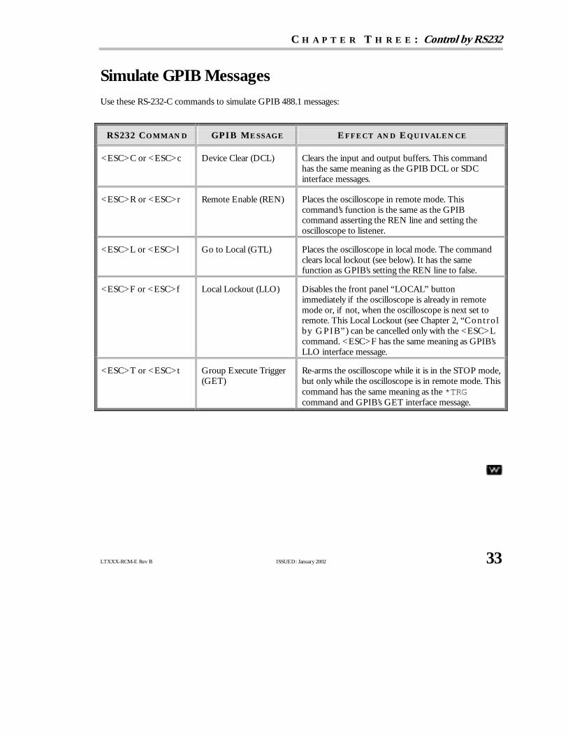
SimulateGPIB Messages
Use these RS-232-C commands to simulate GPIB 488.1 messages:
RS232 CO M M AN D GPI B M E SSAG E E F F E CT AN D E Q U I V AL E N CE
<ESC>C or <ESC>c Device Clear (DCL) Clears the input and output buffers. This commandhas the same meaning as the GPIB DCL or SDCinterface messages.
<ESC>R or <ESC>r Remote Enable (REN) Places the oscilloscope in remote mode. Thiscommand’s function is the same as the GPIBcommand asserting the REN line and setting theoscilloscope to listener.
<ESC>L or <ESC>l Go to Local (GTL) Places the oscilloscope in local mode. The commandclears local lockout (see below). It has the samefunction as GPIB’s setting the REN line to false.
<ESC>F or <ESC>f Local Lockout (LLO) Disables the front panel “LOCAL” buttonimmediately if the oscilloscope is already in remotemode or, if not, when the oscilloscope is next set toremote. This Local Lockout (see Chapter 2, “Controlby GPIB” ) can be cancelled only with the <ESC>Lcommand. <ESC>F has the same meaning as GPIB’sLLO interface message.
<ESC>T or <ESC>t Group Execute Trigger(GET)
Re-arms the oscilloscope while it is in the STOP mode,but only while the oscilloscope is in remote mode. Thiscommand has the same meaning as the*TRGcommand and GPIB’s GET interface message.

34 ISSUED: January 2002 LTXXX-RCM-E Rev B
C H A P T E R F O U R : Understand and Manage Waveforms
In this chapter, see how
To learn how waveforms are structured
To inspect waveform contents
To transfer waveforms rapidly
LTXXX-RCM-E Rev B ISSUED: January 2002 35
C H A P T E R F O U R Understand and Manage Waveforms
KnowYourWaveform
A waveform can be said to have two main parts. The first is its basic data array: rawdata values from theoscilloscope’s ADCs (Analog-to-Digital Converters) obtained in the waveform’s capture. The second is thedescription that accompanies this rawdata: the vertical and horizontal scale or time of day, for example,necessary for a full understanding of the information contained in the waveform.
You can access this information by remote control using theINSPECT? query (see page 36), which interpretsit in an easily understood ASCII text form. And you can rapidly transfer the information using theWAVEFORM? query (see page 37). Or write it back into the oscilloscope with theWAVEFORM command (page42).
Your Waverunner oscilloscope contains a data structure, or template (see Appendix II), which provides adetailed description of howwaveform information is organized. Although a sample template is provided withthis manual, we suggest you use theTEMPLATE? query to access the Waverunner template in the oscilloscopeitself (the template may change as your oscilloscope’s firmware is enhanced).
You can also store waveforms in preformatted ASCII output, for popular spreadsheet and math processingpackages, using the STORE and STORE_SETUP commands. Also see Chapter 12, “Use Waverunnerwith PC ,” of the Operator’s Manual.
LOGICAL DATA BLOCKS
Each of your waveforms will normally contain at least a waveform descriptor and data array block. However,other blocks may also be present in more complex waveforms.
Waveform Descriptor block (WAVEDESC): This includes all the information necessary to reconstitute thedisplay of the waveform from the data, including: hardware settings at the time of acquisition, the exact time ofthe event, kinds of processing performed, your oscilloscope name and serial number, the encoding format usedfor the data blocks, and miscellaneous constants.
Optional User-provided Text block (USERTEXT): Use theWFTX command to put a title or description ofa waveform into this block, and theWFTX? query for an alternative way to read it. This text block can hold upto 160 characters. Display them as four lines of 40 characters by selecting “Text & Times” from the statusmenu, using Waverunner front panel controls (see the Operator’s Manual).
Sequence Acquisition Times block (TRIGTIME): This is needed for sequence acquisitions to record theexact timing information for each segment. It contains the time of each trigger relative to the trigger of thefirst segment, as well as the time of the first data point of each segment relative to its trigger.
Random interleaved sampling times block (RISTIME): This is required for RIS acquisitions to record theexact timing information for each segment.

P A R T O N E : A B O U T R E M O T E C O N T R O L
36 ISSUED: January 2002 LTXXX-RCM-E Rev B
First data array block (SIMPLE or DATA_ARRAY_1): This is the basic integer data of the waveform. Itcan be rawor corrected ADC data or the integer result of waveform processing.
Second data array block (DATA_ARRAY_2): This is a second data array, needed to hold the results ofprocessing functions such as Extrema or FFT math functions:
E XT R E M A F F T
DATA_ARRAY_1 Roof trace Real part
DATA_ARRAY_2 Floor trace Imaginary part
NOTE: The Waverunner templatealso describes an array named DUAL.But this is simply a way to allow theINSPECT? command to examine thetwo data arrays together.
INSPECT WAVEFORM CONTENTS
Use theINSPECT? query to examine the contents of your waveform. You can use it on both of the mainwaveform parts. Its most basic form is: INSPECT? “name”, the template giving you the name of adescriptor item or data block. The answer is returned as a single string, but may cover many lines. Some typicaldialogue follows:
Question C1:INSPECT? “VERTICAL_OFFSET”
Response C1:INSP “VERTICAL_OFFSET: 1.5625e−03”
Question C1:INSPECT? “TRIGGER_TIME”
Response C1:INSP “TRIGGER_TIME: Date = FEB 17, 1994, Time = 4: 4:29.5580”
You can also use INSPECT? to provide a readable translation of the full waveform descriptor block usingINSPECT? “WAVEDESC”. Again, the template will give you the details for interpretation of each of theparameters. Use, too, INSPECT? “SIMPLE” to examine the measured data values of a waveform. For anacquisition with 52 points, for example:
INSPECT? “SIMPLE”C1:INSP “0.0005225 0.0006475 −0.00029 −0.000915 2.25001E−0 0.0008350.0001475 −0.0013525 −0.00204 −4E−05 0.0011475 0.0011475
−0.000915 −0.00179 −0.0002275 0.0011475 0.001085 −0.00079−0.00179 −0.0002275 0.00071 0.00096 −0.0003525 −0.001040.0002725 0.0007725 0.00071 −0.0003525 −0.00129 −0.00022750.0005225 0.00046 −0.00104 −0.00154 0.0005225 0.00127250.001335 −0.0009775 −0.001915 −0.000165 0.0012725 0.00096
−0.000665 −0.001665 −0.0001025 0.0010225 0.00096 −0.0003525−0.000915 8.50001E−0 0.000835 0.0005225“

C H A P T E R F O U R : Understand and Manage Waveforms
LTXXX-RCM-E Rev B ISSUED: January 2002 37
The numbers in the table above are the fully converted measurements in volts. When the data block containsthousands of items the string will contain a great many lines.
Depending on the application, you may prefer the data in its raw form, with either a BYTE (8 bits) or aWORD (16 bits) for each data value. In that case, use the relations INSPECT? “SIMPLE”,BYTE withWAVEFORM?. The examination of data values for waveforms with two data arrays can be performed asfollows:
INSPECT? “DUAL” to get pairs of data values on a single line
INSPECT? “DATA_ARRAY_1” to get the values of the first data array
INSPECT? “DATA_ARRAY_2” to get the values of the second data array.
INSPECT? has its limitations; it is useful, but also wordy. As a query only, INSPECT? cannot be used to senda waveform back to the oscilloscope. If you want to do this and you want the information quickly, you shouldinstead useWAVEFORM. With WAVEFORM_SETUP it is possible to examine just a part of the waveform or asparsed form of it. See the following pages.
If you’re a BASIC user you might also find it convenient to useINSPECT? and WAVEFORM? together toconstruct files containing a version of the waveform descriptor that both you and BASIC can read. Using astored waveform, this can be done in a format suitable for retransfer to Waverunner with MC:INSPECT?“WAVEDESC”;WAVEFORM?, and then placing the response directly into a disk file.
USE THE WAVEFORM QUERY
Use theWAVEFORM? query to transfer waveform data in block formats defined by the IEEE-488.2 standard.You can then download the response back to your Waverunner by using theWAVEFORM command. All yourwaveform’s logical blocks can be read with the queryC1:WAVEFORM? Completeness, as well as time andspace are the advantages of this approach when you have to read many waveforms with the same acquisitionconditions, or when you are interested only in large amounts of raw integer data. Moreover, you can chooseany single block for reading with a query such as C1:WAVEFORM? DAT1. See Part Two for the various blocknames.
You can place the binary response to a query of theform C1:WAVEFORM? or C1:WAVEFORM? ALLin a disk file, then dump it using the GPIB bus. Dothis with default settings to showthe hexadecimaland ASCII form, as on the following page.
NN OOTTEE :: A waveform query response can easily bea block containing over 16 million bytes if it is inbinary format, and twice as much if the HEXoption is used.

P A R T O N E : A B O U T R E M O T E C O N T R O L
38 ISSUED: January 2002 LTXXX-RCM-E Rev B
B YT E O F F SE T
N U M B E RB I N AR Y CO N T E N T S I N H E XAD E CI M AL
ASCI I T R AN SL AT I O N
(.... = U N I N T E R E ST I N G)
C1:WFALL,#9000000450
WAVEDESC........LECROY_2_2..................................................LECROYLT344....
016
3248648096112128144160176192208224240256272288304320336352
367368384400416432448464
0112743597591107123139155171187203219235251267283299315331
01173349658197
43 31 3A 57 46 20 41 4C 4C 2C 23 39 30 30 30 3030 30 34 35 30
57 41 56 45 44 45 53 43 00 00 0000 00 00 00 00 4C 45 43 52 4F 59 5F 32 5F 32 0000 00 00 00 00 00 01 00 00 00 00 01 5A 00 00 0000 00 00 00 00 00 00 00 00 00 00 00 00 00 00 0000 00 00 00 68 00 00 00 00 00 00 00 00 00 00 0000 4C 45 43 52 4F 59 39 33 37 34 4C 00 00 00 0000 37 84 09 40 00 00 00 00 00 00 00 00 00 00 0000 00 00 00 00 00 00 00 34 00 00 00 34 00 00 0032 00 00 00 00 00 00 00 33 00 00 00 00 00 00 0001 00 00 00 00 00 00 00 01 00 00 00 01 00 00 0000 34 83 12 6F 3A 0D 8E C9 46 FE 00 00 C7 00 0000 00 08 00 01 32 2B CC 77 BE 6B A4 BB 51 A0 69BB BE 6A D7 F2 A0 00 00 00 56 00 00 00 00 00 0000 00 00 00 00 00 00 00 00 00 00 00 00 00 00 0000 00 00 00 00 00 00 00 00 00 00 00 00 00 00 0000 00 00 00 00 00 00 00 00 53 00 00 00 00 00 0000 00 00 00 00 00 00 00 00 00 00 00 00 00 00 0000 00 00 00 00 00 00 00 00 00 00 00 00 00 00 0000 00 00 00 00 00 00 00 00 00 00 00 00 40 3B 0000 00 00 00 00 17 0A 05 02 07 C8 00 00 00 00 0000 00 00 00 00 00 00 00 01 00 0E 00 04 3F 80 0000 00 0A 00 00 3F 80 00 00 3A 0D 8E C9 00 00
1100 13 00 04 00 FA 00 09 00 16 00 0B 00 F3 00 E800 08 00 1B 00 1B 00 FA 00 EC 00 05 00 1B 00 1A00 FC 00 EC 00 05 00 14 00 18 00 03 00 F8 00 0D00 15 00 14 00 03 00 F4 00 05 00 11 00 10 00 F800 F0 00 11 00 1D 00 1E 00 F9 00 EA 00 06 00 1D00 18 00 FE 00 EE 00 07 00 19 00 18 00 03 00 FA00 0A 00 16 00 11 00
471 (Terminator) 0A
A bove: To illustrate the contents of the logical block s, the relevant parts have been separated. Tomake counting easier, the corresponding Byte Offset numbering has been restarted each time a newblock begins. The A S CI I translation, only part of which is shown, has been similarly split andhighlighted, showing how its parts correspond to the binary contents.

C H A P T E R F O U R : Understand and Manage Waveforms
LTXXX-RCM-E Rev B ISSUED: January 2002 39
On the facing page... The first 10 bytes translate into ASCII and resemble the simple beginning of a queryresponse. These are followed by the string#9000000450, the beginning of a binary block in which nineASCII integers are used to give the length of the block (450 bytes). The waveform itself starts immediatelyafter this, at Byte 21. The very first byte is 0, as it is for the first byte in each block.
The first object is a DESCRIPTOR_NAME, a string of 16 characters with the valueWAVEDESC.
Then, 16 bytes after the beginning of the descriptor, at Byte 37, we find the beginning of the next string: theTEMPLATE_NAME with the valueLECROY_2_2.
Several other parameters follow. The INSTRUMENT_NAME, LECROYLT344, 76 bytes from the descriptorstart (Byte 97), is easily recognizable. On the preceding line, 38 bytes after the descriptor (Byte 59), a four-byteinteger gives the length of the descriptor: WAVE_DESCRIPTOR = 00 00 01 5A (hex) = 346.
At 60 bytes from the descriptor start (Byte 81) we find another four-byte integer giving the length of the dataarray: WAVE_ARRAY_1 = 00 00 00 68 (hex) = 104.
And at 116 bytes after the descriptor (Byte 137), yet another four-byte integer gives the number of data points:WAVE_ARRAY_COUNT = 00 0000 34 (hex) = 52.
Nowwe knowthat the data will start at 346 bytes from the descriptor’s beginning (Byte 367), and that each ofthe 52 data points will be represented by two bytes. The waveform has a total length of 346 + 104, which is thesame as the ASCII string indicated at the beginning of the block. The final 0A at Byte 471 is the NL characterassociated with the GPIB message terminator <NL><EOI>.
As the example was taken using an oscilloscope with an eight-bit ADC, we see the eight bits followed by a 0byte for each data point. However, for many other kinds of waveform this second byte will not be zero and willcontain significant information. The data is coded in signed form (two’s complement) with values ranging from−32768 = 8000 (hex) to 32767 = 7FFF (hex). If we had chosen to use the BYTE option for the data format,the values would have been signed integers in the range −128 = 80 (hex) to 127 = 7F (hex). The ADC valuesare mapped to the display grid in the following way:
0 is located on the grid’s center axis
127 (BYTE format) or 32767 (WORD format) is located at the top of the grid
−128 (BYTE format) or −32768 (WORD format) is located at the bottom of the grid.
INTERPRET VERTICAL DATA
Knowing nowhowto decipher the data, you may wish to convert it to the appropriate measured values. Thevertical reading for each data point depends on the vertical gain and the vertical offset given in the descriptor.For acquisition waveforms, this corresponds to the volts/div and voltage offset selected after conversion forthe data representation being used. The template tells us that the vertical gain and offset can be found at Bytes156 and 160 and that they are stored as floating point numbers in the IEEE 32-bit format. An ASCII stringgiving the vertical unit is to be found in VERTUNIT, Byte 196. The vertical value is given by the relationship:value = VERTICAL_GAIN × data − VERTICAL_OFFSET, where:

P A R T O N E : A B O U T R E M O T E C O N T R O L
40 ISSUED: January 2002 LTXXX-RCM-E Rev B
VERTICAL_GAIN 2.44141e−07 from the floating point number 3483 126f at Byte 177
VERTICAL_OFFSET 0.00054 from the floating point number 3A0D 8EC9 at Byte 181
VERTICAL_UNIT V = volts from the string 5600 ... at Byte 217
Therefore:
since data[4] = FA00 = 64000 from the hexadecimal word FA00 at byte 371. Overflowsthe maximum. 16 bit value of 32767, so must be a negative value. Usingthe two’s complement conversion 64000−216 = −1536
value[4] = −0.000915 V as stated in the inspect command.
If the computer or the software available is not able to understand the IEEE floating point values, use thedescription in the template.
The data values in a waveform may not all correspond to measured points. FIRST_VALID_PNT andLAST_VALID_PNT give the necessary information. The descriptor also records the SPARSING_FACTOR,the FIRST_POINT, and the SEGMENT_INDEX to aid interpretation if the options of theWAVEFORM_SETUP command have been used.
For sequence acquisitions the data values for each segment are given in their normal order and the segmentsare read out one after the other. The important descriptor parameters are the WAVE_ARRAY_COUNT andthe SUBARRAY_COUNT, giving the total number of points and the number of segments.
For waveforms such as the extrema and the complex FFT there will be two arrays — one after the other — forthe two of the result.
CALCULATE A DATA POINT’S HORIZONTAL POSITION
Each vertical data value has a corresponding horizontal position, usually measured in time or frequency units.The calculation of this position depends on the type of waveform. Each data value has a position, i, in theoriginal waveform, with i = 0 corresponding to the first data point acquired. The descriptor parameterHORUNIT gives a string with the name of the horizontal unit.
Single Sweep waveforms: x[i] = HORIZ_INTERVAL × i + HORIZ_OFFSET. For acquisition waveformsthis time is from the trigger to the data point in question. It will be different from acquisition to acquisitionsince the HORIZ_OFFSET is measured for each trigger. In the case of the data shown above this means:
HORIZ_INTERVAL = 1e−08 from the floating point number 322b cc77 at Byte 194
HORIZ_OFFSET = −5.149e−08 from the double precision floating point number be6b a4bb51a0 69bb at Byte 198
HORUNIT = S = seconds from the string 5300 ... at Byte 262
This gives: x[0] = −5.149e−08 Sx[1] = −4.149e−08 S.

C H A P T E R F O U R : Understand and Manage Waveforms
LTXXX-RCM-E Rev B ISSUED: January 2002 41
Sequence waveforms: are really many independent acquisitions, so each segment will have its own horizontaloffset. These can be found in the TRIGTIME array.
For the n’th segment:
x[i,n] = HORIZ_INTERVAL × i + TRIGGER_OFFSET[n].
The TRIGTIME array can contain up to 200 segments of timing information with two eight-byte doubleprecision floating point numbers for each segment.
RIS (Random Interleaved Sampling) waveforms: are composed of many acquisitions interleaved together.The descriptor parameter, RIS_SWEEPS gives the number of acquisitions. The i’th point will belong to them’th segment where:
m = i modulo (RIS_SWEEPS) will have a value between 0 and RIS_SWEEPS −1.
Then with: j = i − m
x[i] = x[j,m] = HORIZ_INTERVAL × j + RIS_OFFSET[m],
where the RIS_OFFSETs can be found in the RISTIME array. There can be up to 100 eight-byte doubleprecision floating point numbers in this block. The instrument tries to get segments with times such that:RIS_OFFSET[i] ≅ PIXEL_OFFSET + (i − 0.5) × HORIZ_INTERVAL.
Thus, taking as an example a RIS with RIS_SWEEPS = 10, HORIZ_INTERVAL = 1 ns, andPIXEL_OFFSET = 0.0, we might find for a particular event that:
RIS_OFFSET[0] = −0.5 ns RIS_OFFSET[1] = 0.4 ns
RIS_OFFSET[2] = 1.6 ns RIS_OFFSET[3] = 2.6 ns
RIS_OFFSET[4] = 3.4 ns RIS_OFFSET[5] = 4.5 ns
RIS_OFFSET[6] = 5.6 ns RIS_OFFSET[7] = 6.4 ns
RIS_OFFSET[8] = 7.6 ns RIS_OFFSET[9] = 8.5 ns
and therefore:
x[0] = RIS_OFFSET[0] = −0.5 ns
x[1] = RIS_OFFSET[1] = 0.4 ns...
x[9] = RIS_OFFSET[9] = 8.5 ns
x[10] = 1 ns × 10 + (−0.5) = 9.5 ns
x[11] = 1 ns × 10 + 0.4 = 10.4 ns...
x[19] = 1 ns ´ 10 + 8.5 = 18.5 ns
x[20] = 1 ns ´ 20 + (−0.5) = 19.5 ns....

P A R T O N E : A B O U T R E M O T E C O N T R O L
42 ISSUED: January 2002 LTXXX-RCM-E Rev B
USE THE WAVEFORM COMMAND
Waveforms you read with the WAVEFORM? query (page 37)can be sent back into your Waverunner oscilloscope usingWAVEFORM and related commands. Since the descriptorcontains all of the necessary information, you need not beconcerned with any of the communication format parameters.The oscilloscope will learn all it needs to knowfrom thewaveform.
TTIIPP:: Because waveforms can only be sentback to Waverunner memory traces (M1,M2, M3, M4), consider removing orchanging the prefix (C1 orCHANNEL_1)in the response to the WF? query. SeePart Two for examples.
To ensure that the descriptor is coherent, however, when you synthesize waveforms for display or comparisonread out a waveform of the appropriate size and then replace the data with the desired values.
Here are among the many ways to useWAVEFORM and its related commands to simplify or speed up work:
Partial Waveform Readout: UseWAVEFORM_SETUP to specify a short part of a waveform for readout, aswell as to select a sparsing factor for reading every n’th data point only.
Byte Swapping: TheCOMM_ORDER command allows you to swap two bytes of data presented in 16-bit wordformat, in the descriptor or in the the data/ time arrays, when sending the data via GPIB or RS-232-C ports.Depending on the computer system used, this will alloweasier data interpretation. For Intel-based computers,you should send the data with the LSB first; the command should beCORD LO. For Motorola-basedcomputers, send the data with the MSB first (CORD HI) — the default at power-up.
NN OOTTEE :: Data written to Waverunner hard disk or floppy drive, or to the optional PC memory carddrive, will always remain in LSB first, the default DOS format. Thus you cannot use the CORDcommand in these cases, as it is only for data sent via the GPIB and RS-232-C ports.
Data Length, Block Format, and Encoding: COMM_FORMAT gives you control over these parameters.If you do not need the extra precision of the lower order byte of the standard data value, the BYTE optionwill enable you to save by a factor of two the amount of data transferred or stored. If the computer you areusing cannot read binary data, the HEX option allows a response form in which the value of each byte is givenby a pair of hexadecimal digits.
Data-Only Transfers: COMM_HEADER OFF enables a response to WF? DAT1 with data only (theC1:WFDAT1 will disappear). If you have also specified COMM_FORMAT OFF,BYTE,BIN, the response will bedata bytes only (the#90000nnnnn will disappear — see page 38).
Formatting for RS-232-C Users: The COMM_RS232 command can assist by splitting the very long WF?response into individual lines.

C H A P T E R F O U R : Understand and Manage Waveforms
LTXXX-RCM-E Rev B ISSUED: January 2002 43
TransferWaveforms at HighSpeed
You must take several important factors into account if you wish to achieve maximum, continuous datatransfer rates from your Waverunner oscilloscope to the external controller. The single most important ofthese is to limit the amount of work done in the computer. This means that you should avoid writing data todisk wherever possible, minimize operations such as per-data-point computations, and reduce the number ofcalls to the I/O system. To do this, you can try the following:
Reduce the number of points to be transferred and the number of data bytes per point. The pulseparameter capability and the processing functions can save a great deal of computing and a lot of datatransfer time if employed creatively.
Attempt to overlap waveform acquisition with waveform transfer. The oscilloscope is capable oftransferring an already acquired or processed waveform after a newacquisition has been started. The totaltime that Waverunner takes to acquire events will be considerably increased if it is obliged to wait fortriggers (livetime).
Minimize the number of waveform transfers by using Sequence mode to accumulate many triggersfor each transfer. This is preferable to usingWAVEFORM_SETUP to reduce the number of data points fortransfer. It also significantly reduces oscilloscope transfer overhead. For example, you could useARM; WAIT;C1:WF? (wait for the event, transfer the data, and then start a newacquisition). Youcould also “loop” this line in the program as soon as it has finished reading the waveform.

44 ISSUED: January 2002 LTXXX-RCM-E Rev B
C H A P T E R F I V E : CheckWaveformStatus
In this chapter, see how
To use status registers

LTXXX-RCM-E Rev B ISSUED: January 2002 45
C H A P T E R F I V E CheckWaveformStatus
Use Status Registers
A wide range of status registers allows you to quickly determine Waverunner internal processing status at anytime. These registers and the oscilloscope’s status reporting system, which group related functions together, aredesigned to comply with IEEE 488.2 recommendations. Some, such as the Status Byte Register (STB) or theStandard Event Status Register (ESR), are required by the IEEE 488.2 Standard. Others are device specific,including the Command Error Register (CMR) and Execution Error Register (EXR). Those commandsassociated with IEEE 488.2 mandatory status registers are preceded by an asterisk (*).
OVERVIEW
The Standard Event Status Bit (ESB) and the Internal Status Change Bit (INB) in the SBR are summary bits ofthe ESR and the Internal State Change Register (INR). The Message Available Bit (MAV) is set whenever thereare data bytes in the output queue. The Value Adapted Bit (VAB) indicates that a parameter value was adaptedduring a previous command interpretation. For example, if the command TDIV 2.5 US was received, thetimebase would be set to 2 ms/div along with the VAB bit.
The Master Summary Status bit (MSS) indicates a request for service from the oscilloscope. You can only setthe MSS bit if you have enabled one or more of the other STB bits with the Service Request Enable Register(SRE).
All Enable registers (SRE, ESE and INE) are used to generate a bit-wise AND with their associated statusregisters. The logical OR of this operation is reported to the STB register. At power-on, all Enable registers arezero, inhibiting any reporting to the STB.
The ESR primarily summarizes errors, whereas the INR reports internal changes to the instrument. Additionaldetails of errors reported by ESR can be obtained with the queries CMR?, DDR?, EXR? and URR?.
The register structure contains one additional register, not shown on the next page (Fig.1). This is the ParallelPoll Enable Register (PRE), which behaves exactly like the SRE, but sets the “ist” bit used in the Parallel Poll.Read the “ist” bit with the*IST? query.
Example: If you were to send the erroneous command TRIG_MAKE SINGLE to your Waverunner, theoscilloscope would reject it and set the Command Error Register (CMR) to the value 1 (unrecognizedcommand/query header). The non-zero value of CMR would be reported to Bit 5 of the Standard EventStatus Register (ESR), which is then set. Nothing further would occur unless the corresponding Bit 5 of theStandard Event Status Enable Register (ESE) was set with the command *ESE 32, enabling Bit 5 of ESR tobe set for reporting to the summary bit ESB of the STB.

46 ISSUED: January 2002 LTXXX-RCM-E Rev B
0
0
0
1
1
11
2
2
2
3
3
33
4
4
415 12 11 10 9
5
5
67
7
7
3 0124567
&
&
&
&
&
&
&
&
&
&
&&
&&
&
&
&
&
Logi
calO
R
Logi
calO
R
ServiceRequestGeneration
E SB MAV VAB INB
Standard E ventStatus RegisterRead by *ESR?
See command for the interpretation of the bits.INR
Power ONUser request ( )URR?Command error found ( )CMR?E xecution errordetected ( )EXR?Device specific error ( )DDR?Query errorRequest control (unused)Operation complete
Internal StateChange RegisterRead byINR?
Internal State ChangeE nable RegisterSet byRead by
INE nINE?
Service RequestE nable RegisterSet byRead by
*SRE n*SRE?
Standard E ventStatus E nable RegisterSet byRead by
*ESE n*ESE?
Status Byte RegisterRead by Serial PollRead by *STB?
012315 12 11 10 9 4
RQSMSS
&&
&
&&
Logi
calO
R
F igure 1.S tatus R egister S tructure
C H A P T E R F I V E : CheckWaveformStatus
LTXXX-RCM-E Rev B ISSUED: January 2002 47
If you enabled the setting of the ESB summary bit in STB, again nothing would occur unless you enabledfurther reporting by setting the corresponding bit in the Service Request Enable Register with the command*SRE 32. The generation of a non-zero value of CMR would ripple through to MSS, generating a ServiceRequest (SRQ).
You can read the value of CMR and simultaneously reset to zero at any time with the command CMR?. Theoccurrence of a command error can also be detected by analyzing the response to *ESR?. However, if youmust survey several types of potential errors, it is usually far more efficient to enable propagation of the errorsof interest into the STB with the enable registers ESE and INE.
To summarize: a command error (CMR) sets Bit 5 of ESR if
a. Bit 5 of ESE is set, ESB of STB is also set, or
b. Bit 5 of SRE is set, MSS/RQS of STB is also set and a Service Request is generated.
STATUS BYTE REGISTER (STB)
STB is the Waverunner central reporting structure. It is made up of eight single-bit summary messages, threeof which are unused, that reflect the current status of the oscilloscope’s associated data structures:
Bit 0 is the INB summary bit of the Internal State Change Register. It is set if any INR bits are set,provided they are enabled by the corresponding bit of the INE register.
Bit 2 is the VAB bit, indicating that a parameter value was adapted during a previous commandinterpretation.
Bit 4 is the MAV bit, indicating that the interface output queue is not empty.
Bit 5 is the summary bit ESB of the ESR. It is set if any of the bits of the ESR are set, provided they areenabled by the corresponding bit of the ESE register.
Bit 6 is either the MSS or RQS (Request for Service) bit.
You can read the STB using the*STB? query. It reads and clears the STB, in which case Bit 6 is the MSS bit,And it indicates whether the oscilloscope has any reason to request service. The response to the queryrepresents the binary weighted sum of the register bits. The register is cleared by*STB?, ALST?, *CLS, orwith Waverunner powering up.
Another way to read the STB is using the serial poll (see Chapter 2). In this case, Bit 6 is the RQS bit, indicatingthat the instrument has activated the SRQ line on the GPIB. The serial poll clears only the RQS bit. And theSTB’s MSS bit, and any other bits which caused MSS to be set, will remain set after the poll. These bits must bereset.
STANDARD EVENT STATUS REGISTER (ESR)
ESR is a 16-bit register reflecting the occurrence of events. ESR bit assignments have been standardized byIEEE 488.2. Only the lower eight bits are currently in use.

48 ISSUED: January 2002 LTXXX-RCM-E Rev B
Read ESR using*ESR?. The response is the binary weighted sum of the register bits. The register is clearedwith *ESR? or ALST?, or with *CLS or powering on the scope.
Example: The response message*ESR 160 tells you that a command error occurred and that the ESR isbeing read for the first time after power-on. The value 160 can be broken down into 128 (Bit 7) plus 32 (bit 5).See the table with theESR command description in Part Two for the conditions corresponding to the bits set.
The Power ON bit appears only on the first *ESR? query after power-on, as the query clears the register. Youcan determine this type of command error by reading the CMR with CMR?. It is not necessary that you read,or simultaneously clear, this register in order to set the CMR bit in the ESR on the next command error.
STANDARD EVENT STATUS ENABLE REGISTER (ESE)
This register allows you to report one or more events in the ESR to the ESB summary bit in the STB.
Modify ESE with *ESE and clear it with *ESE 0, or with power-on. Read it with *ESE?.
Example: Use*ESE 4 to set bit 2 (binary 4) of the ESE Register, and enable query errors to be reported.
SERVICE REQUEST ENABLE REGISTER (SRE)
SRE specifies which Status Byte Register summary bit or bits will bring about a service request. This registerconsists of eight bits. Setting a bit allows the summary bit located at the same bit position in the SBR togenerate a service request, provided that the associated event becomes true. Bit 6 (MSS) cannot be set and isalways reported as zero in response to *SRE?.
Modify SRE with *SRE and clear it with *SRE 0, or with power-on. Read it using*SRE?.
PARALLEL POLL ENABLE REGISTER (PRE)
This specifies which Status Byte Register summary bit or bits will set the “ist” individual local message. PRE issimilar to SRE, but is used to set the parallel poll “ist” bit rather than MSS.
The value of the “ist” may also be read without a Parallel Poll via the query*IST?. The response indicateswhether or not the “ist” message has been set (values are 1 or 0).
Modify PRE *PRE and clear it with *PRE 0, or with power-on. Read this register with *PRE?.
Example: Use *PRE 5 to set the register’s bits 2 and 0 (decimal 4 and 1).
INTERNAL STATE CHANGE STATUS REGISTER (INR)
INR reports the completion of a number of internal operations (the events tracked by this 16-bit-wide registerare listed with theINR? description in Part Two).
Read the register usingINR?. The response is the binary weighted sum of the register bits. Clear the registerwith INR? or ALST?, a *CLS command, or with power-on.

C H A P T E R F I V E : CheckWaveformStatus
LTXXX-RCM-E Rev B ISSUED: January 2002 49
INTERNAL STATE CHANGE ENABLE REGISTER (INE)
INE allows one or more events in the Internal State Change Status Register to be reported to the INBsummary bit in the STB.
Modify INE with INE and clear it with INE 0, or after power-on. Read it with INE?.
COMMAND ERROR STATUS REGISTER (CMR)
This register contains the code of the last command error detected by the oscilloscope. List these error codesusingCMR?.
Read CMR with CMR?. The response is the error code. Clear the register with a CMR? or ALST? query, a*CLS command, or with power-on.
DEVICE DEPENDENT ERROR STATUS REGISTER (DDR)
DDR indicates the type of hardware errors affecting your Waverunner. Individual bits in this register reportspecific hardware failures. List them usingDDR?.
Also read this register using theDDR? query. The response is the binary weighted sum of the error bits. Clearit with another DDR? or with ALST?, a *CLS command, or with power-on.
EXECUTION ERROR STATUS REGISTER (EXR)
EXR contains the code of the last execution error detected by the oscilloscope. List these error codes withEXR?.
Read the register, again using theEXR? query. The response is the error code. Clear with another EXR? orwith ALST?, a *CLS command, or with power-on.
USER REQUEST STATUS REGISTER (URR)
Finally, URR contains the identification code of the last menu button pressed. List these codes with URR?.
Read URR using the same query. The response is the decimal code associated with the selected menu button.And clear the register with another URR?, or with ALST?, a *CLS command, or with power-on.

50 ISSUED: January 2002 LTXXX-RCM-E Rev B
BLANK PAGE

C H A P T E R F I V E : CheckWaveformStatus
LTXXX-RCM-E Rev B ISSUED: January 2002 51
BLANK PAGE
LTXXX-RCM-E Rev B ISSUED: January 2002 51
PPAARRTT TT WWOO
CC OO MM MM AA NN DD SSPart Two lists and describes the commands and queries you will need to remotely operate yourWaverunner oscilloscope.

52 ISSUED: January 2002 LTXXX-RCM-E Rev B
P A R T T W O : C O M M A N D S
In this part of the manual, you’ll find the commands and queries.
To run Waverunner remotely.

LTXXX-RCM-E Rev B ISSUED: January 2002 53
P A R T T W O : C O M M A N D S
Use WaverunnerCommands and Queries
This part of the manual lists and describes the remote control commands and queries recognized byWaverunner. You can execute all of them in either local or remote state. Where commands or queries forspecial options are not included, you will find them in those options’ dedicated Operator’s Manuals.
The commands and queries are listed in alphabetical order according to the long form of their name. Forexample, the description of ATTENUATION, whose short form is ATTN, is listed before that of AUTOSETUP, whose short form is ASET. Each command or query description starts on a newpage. The name(header) is given in both long and short form at the top of the first page of each description.
Queries perform actions such as obtaining information. They are recognized by? following their headers.Many commands can be used as queries with the question mark added.
A brief explanation of the operation performed by the command or query is followed the formal syntax, withthe full-name header given in lower-case characters and the short form derived from it in upper-case characters(e.g., DoT_JoiN for DTJN). Where applicable, the syntax of the query is given with the format of itsresponse. A short example illustrating a typical use is also presented. The GPIB examples assume that thecontroller is equipped with a National Instruments interface board, which calls to the related interfacesubroutines in BASIC. The device name of the oscilloscope is defined as SCOPE%.
Use the two tables that precede the descriptions to quickly find a command or query. The first of these lists thecommands and queries in alphabetical order according to their short form. The second table groups themaccording to the subsystem or category they belong to.
COMMAND NOTATION
The following notation is used in the commands:
<< >> Angular brackets enclose words that are used as placeholders, of which there are two types: the headerpath and the data parameter of a command.
:: == A colon followed by an equals sign separates a placeholder from the description of the type and rangeof values that can be used in a command instead of the placeholder.
Braces enclose a list of choices, one of which must be made.
[[ ]] Square brackets enclose optional items.
…… An ellipsis indicates that the items left and right of it can be repeated any number of times.

P A R T T W O : C O M M A N D S
54 ISSUED: January 2002 LTXXX-RCM-E Rev B
Example: consider the syntax notation for the command to set the vertical input sensitivity:
1. <channel> : VOLT_DIV <v_gain>
2. <channel> : = C1, C2
3. <v_gain> : = 5.0 mV to 2.5 V
The first line shows the formal appearance of the command: <channel> denotes the placeholder for theheader path; <v_gain> is the placeholder for the vertical gain value.
The second line indicates that either C1 or C2 must be chosen for the header path.
The third line means that the actual vertical gain can be set to any value from 5 mV to 2.5 V.

Remote Control Commands and Queries
LTXXX-RCM-E Rev B ISSUED: January 2002 55
Table of Commands and Queries — By Short Form...PAGE
NO.SHORT
FORM
LONG FORM SUBSYSTEM
(CATEGORY)WHAT THE COMMAND OR QUERY DOES
66 ACAL AUTO_CALIBRATE MISCELLANEOUS Enables or disables automatic calibration.
63 ALST? ALL_STATUS? STATUS Reads and clears the contents of all status registers.
64 ARM ARM_ACQUISITION ACQUISITION Changes acquisition state from “stopped” to “single”.
67 ASCR AUTO_SCROLL DISPLAY Controls theAuto Scroll viewing feature.
68 ASET AUTO_SETUP ACQUISITION Adjusts vertical, timebase and trigger parameters.
65 ATTN ATTENUATION ACQUISITION Selects the vertical attenuation factor of theprobe.
71 BUZZ BUZZER MISCELLANEOUS Controls the built-in piezo-electric buzzer.
69 BWL BANDWIDTH_LIMIT ACQUISITION Enables/disables bandwidth-limiting low-pass filter.
72 *CAL? *CAL? MISCELLANEOUS Performs complete internal calibration of oscilloscope.
84 CFMT COMM_FORMAT COMMUNICATION Selects the format for sending waveform data.
86 CHDR COMM_HEADER COMMUNICATION Controls formatting of query responses.
87 CHLP COMM_HELP COMMUNICATION Controls operational level of theRC Assistant.
88 CHL COMM_HELP_LOG COMMUNICATION Returns the contents of theRC Assistant log.
74 CHST CALL_HOST DISPLAY Allows manual generation of a service request (SRQ).
75 CLM CLEAR_MEMORY FUNCTION Clears the specified memory.
77 *CLS *CLS STATUS Clears all status data registers.
76 CLSW CLEAR_SWEEPS FUNCTION Restarts the cumulative processing functions.
78 CMR? CMR? STATUS Reads and clears theCommand error Register (CMR).
80 COLR COLOR DISPLAY Selects color of individual on-screen objects.
89 CORD COMM_ORDER COMMUNICATION Controls the byte order of waveform data transfers.
91 CORS COMM_RS232 COMMUNICATION Sets remote control parameters of the RS-232-C port.
73 COUT CAL_OUTPUT MISCELLANEOUS Sets signal typeput out at theCAL connector.
94 CPL COUPLING ACQUISITION Selects the specified input channel’s coupling mode.
95 CRMS CURSOR_MEASURE CURSOR Specifies the type of cursor/parameter measurement.
98 CRST? CURSOR_SET? CURSOR Allows positioning of any one of eight cursors.
100 CRVA? CURSOR_VALUE? CURSOR Returns trace values measured by specified cursors.
83 CSCH COLOR_SCHEME DISPLAY Selects the display color scheme.
103 DATE DATE MISCELLANEOUS Changes the date/timeof the internal real-time clock.
104 DDR? DDR? STATUS Reads, clears theDeviceDependent Register (DDR).
106 DEF DEFINE FUNCTION Specifies math expression for function evaluation.
112 DELF DELETE_FILE MASS STORAGE Deletes files from mass storage.
113 DIR DIRECTORY MASS STORAGE Creates and deletes file directories.
216 DISP DISPLAY DISPLAY Controls the display screen.
102 DPNT DATA_POINTS DISPLAY Controls bold/single pixel display of sample points.
116 DTJN DOT_JOIN DISPLAY Controls the interpolation lines between data points.
117 DZOM DUAL_ZOOM DISPLAY Sets horizontal magnification and positioning.
118 EKEY ENABLE_KEY DISPLAY Allows use of theKEY command in local mode.

P A R T T W O : C O M M A N D S
56 ISSUED: January 2002 LTXXX-RCM-E Rev B
PAGE
NO.SHORT
FORM
LONG FORM SUBSYSTEM
(CATEGORY)WHAT THE COMMAND OR QUERY DOES
119 *ESE *ESE STATUS Sets the Standard Event Status Enable register(ESE).
120 *ESR? *ESR? STATUS Reads, clears the Event Status Register (ESR).
123 EXR? EXR? STATUS Reads, clears the EXecution error Register (EXR).
125 FATC FAT_CURSOR DISPLAY Controls width of cursors.
127 FCR FIND_CTR_RANGE FUNCTION Automatically sets the center and width of a histogram.
128 FCRD FORMAT_CARD MISCELLANEOUS Formats thememory card.
130 FFLP FORMAT_FLOPPY MISCELLANEOUS Formats a floppydisk.
132 FHDD FORMAT_HDD MASS STORAGE Formats the removable hard disk.
126 FLNM FILENAME MASS STORAGE Changes default filenames.
135 FRST FUNCTION_RESET FUNCTION Resets a waveform-processing function.
134 FSCR FULL_SCREEN DISPLAY Selects magnified viewformat for the grid.
136 GBWL GLOBAL_BWL ACQUISITION Enables/disables theGlobal Bandwidth Limit.
137 GRID GRID DISPLAY Specifies single-, dual- or quad-modegrid display.
138 HCSU HARDCOPY_SETUP HARD COPY Configures the hardcopydriver.
141 HCTR HARDCOPY_TRANSMIT HARD COPY Sends string of ASCII characters to hardcopyunit.
142 HMAG HOR_MAGNIFY DISPLAY Horizontally expands the selected expansion trace.
143 HPOS HOR_POSITION DISPLAY Horizontally positions intensified zone’s center.
145 *IDN? *IDN? MISCELLANEOUS For identification purposes.
152 ILVD INTERLEAVED ACQUISITION Enables/disables random interleaved sampling (RIS).
146 INE INE STATUS Sets the Internal state change Enable register (INE).
147 INR? INR? STATUS Reads, clears INternal state change Register (INR).
149 INSP? INSPECT? WAVEFORMTRANSFER
Allows acquired waveform parts to be read.
151 INTS INTENSITY DISPLAY Sets the grid or trace/text intensity level.
153 IST? IST? STATUS Reads the current state of the IEEE 488.
154 KEY KEY DISPLAY Displays a string in themenu field.
155 LOGO LOGO DISPLAY Displays LeCroy logo at top of grid.
156 MASK MASK CURSOR Invokes Polymask drawand fill tools.
158 MGAT MEASURE_GATE DISPLAY Controls highlighting of themeasurement gate region.
160 MSG MESSAGE DISPLAY Displays a string of characters in the message field.
159 MSIZ MEMORY_SIZE ACQUISITION Selects max. memory length.
161 MZOM MULTI_ZOOM DISPLAY Sets horizontal magnification and positioning.
162 OFST OFFSET ACQUISITION Allows output channel vertical offset adjustment.
163 *OPC *OPC STATUS Sets the OPC bit in the Event Status Register (ESR).
164 *OPT? *OPT? MISCELLANEOUS Identifies oscilloscope options.
167 PACL PARAMETER_CLR CURSOR Clears all current parameters in Custom, Pass/Fail.
168 PACU PARAMETER_CUSTOM CURSOR Controls parameters with customizable qualifiers.
171 PADL PARAMETER_DELETE CURSOR Deletes a specified parameter in Custom, Pass/Fail.
172 PAST? PARAMETER_STATISTICS? CURSOR Returns current statistics parameter values.
173 PAVA? PARAMETER_VALUE? CURSOR Returns current parameter, mask test values.

Remote Control Commands and Queries
LTXXX-RCM-E Rev B ISSUED: January 2002 57
PAGE
NO.SHORT
FORM
LONG FORM SUBSYSTEM
(CATEGORY)WHAT THE COMMAND OR QUERY DOES
183 PECS PER_CURSOR_SET CURSOR Positions independent cursors.
185 PECV? PER_CURSOR_VALUE? CURSOR Returns values measured by cursors.
188 PELT PERSIST_LAST DISPLAY Shows the last trace drawn in a persistencedata map.
186 PERS PERSIST DISPLAY Enables or disables the persistencedisplay mode.
187 PECL PERSIST_COLOR DISPLAY Controls color rendering method of persistence traces.
189 PESA PERSIST_SAT DISPLAY Sets the color saturation level in persistence.
190 PESU PERSIST_SETUP DISPLAY Selects display persistenceduration.
176 PFCO PASS_FAIL_CONDITION CURSOR Adds a Pass/Fail test condition or custom parameter.
178 PFCT PASS_FAIL_COUNTER CURSOR Resets the Pass/Fail acquisition counters.
179 PFDO PASS_FAIL_DO CURSOR Defines desired outcome, actions after Pass/Fail test.
181 PFMS PASS_FAIL_MASK CURSOR Generates tolerancemask on a trace and stores it.
182 PFST? PASS_FAIL_STATUS? CURSOR Returns the Pass/Fail test for a given line number.
166 PNSU PANEL_SETUP SAVE/RECALL Complements the *SAV/*RST commands.
191 *PRE *PRE STATUS Sets the PaRallel poll Enable register (PRE).
192 PRCA? PROBE_CAL? PROBES Performs auto-calibration of connected current probe.
193 PRDG? PROBE_DEGAUSS? PROBES Degausses, calibrates connected current probe.
194 PRNA PROBE_NAME? PROBES Names the probe connected to the oscilloscope.
195 *RCL *RCL SAVE/RECALL Recalls one of five non-volatile panel setups.
198 RCPN RECALL_PANEL SAVE/RECALL Recalls a front panel setup from mass storage.
197 REC RECALL WAVEFORMTRANSFER
Recalls a file from mass storage to internal memory.
196 ROUT REAR_OUTPUT MICELLANEOUS Sets the type of signal put out at rear BNC connector.
199 *RST *RST SAVE/RECALL Initiates a device reset.
201 *SAV *SAV SAVE/RECALL Stores current state in non-volatile internal memory.
202 SCDP SCREEN_DUMP HARD COPY Causes a screen dump to the hardcopydevice.
200 SCLK SAMPLE_CLOCK ACQUISITION Allows control of an external timebase.
203 SCSV SCREEN_SAVE DISPLAY Controls the automatic screen saver.
204 SEL SELECT DISPLAY Selects the specified trace for manual display control.
205 SEQ SEQUENCE ACQUISITION Sets the conditions for the sequencemode acquisition.
207 SLEEP SLEEP MICELLANEOUSMakes the scope wait before it interprets newcommands
208 *SRE *SRE STATUS Sets the Service Request Enable register (SRE).
209 *STB? *STB? STATUS Reads the contents of the IEEE 488.
212 STO STORE WAVEFORMTRANSFER
Stores a trace in internal memory or mass storage.
211 STOP STOP ACQUISITION Immediately stops signal acquisition.
213 STPN STORE_PANEL SAVE/RECALL Stores front panel setup to mass storage.
214 STST STORE_SETUP WAVEFORMTRANSFER
Controls theway in which traces are stored.
215 STTM STORE_TEMPLATE WAVEFORMTRANSFER
Stores thewaveform template to mass storage.

P A R T T W O : C O M M A N D S
58 ISSUED: January 2002 LTXXX-RCM-E Rev B
PAGE
NO.SHORT
FORM
LONG FORM SUBSYSTEM
(CATEGORY)WHAT THE COMMAND OR QUERY DOES
218 TDIV TIME_DIV ACQUISITION Modifies the timebase setting.
216 TDISP TDISP MISCELLANEOUS Changes timedisplay from current to trigger or none.
217 TMPL? TEMPLATE? WAVEFORMTRANSFER
Produces a complete waveform template copy.
219 TRA TRACE DISPLAY Enables or disables the display of a trace.
220 TOPA TRACE_OPACITY DISPLAY Controls the opacity of the trace color.
222 TRCP TRIG_COUPLING ACQUISITION Sets the coupling mode of the specified trigger source.
223 TRDL TRIG_DELAY ACQUISITION Sets the time at which the trigger is to occur.
221 *TRG *TRG ACQUISITION Executes an ARM command.
225 TRLV TRIG_LEVEL ACQUISITION Adjusts the trigger level of the specified trigger source.
226 TRMD TRIG_MODE ACQUISITION Specifies the trigger mode.
227 TRSE TRIG_SELECT ACQUISITION Selects the condition that will trigger acquisition.
230 TRSL TRIG_SLOPE ACQUISITION Sets the trigger slope of the specified trigger source.
231 TRWI TRIG_WINDOW ACQUISITION Sets windowamplitudeon current Edge trigger source.
232 *TST? *TST? MISCELLANEOUS Performs an internal self-test.
233 URR? URR? STATUS Reads, clears User Request status Register (URR).
237 VDIV VOLT_DIV ACQUISITION Sets the vertical sensitivity.
235 VMAG VERT_MAGNIFY DISPLAY Vertically expands the specified trace.
236 VPOS VERT_POSITION DISPLAY Adjusts the vertical position of the specified trace.
238 *WAI *WAI STATUS Required by the IEEE 488.
239 WAIT WAIT ACQUISITION Prevents newanalysis until current is completed.
240 WF WAVEFORM WAVEFORMTRANSFER
Transfers a waveform from controller to scope.
243 WFSU WAVEFORM_SETUP WAVEFORMTRANSFER
Specifies amount of waveform data to go to controller.
245 WFTX WAVEFORM_TEXT WAVEFORMTRANSFER
Documents acquisition conditions.
246 XYAS? XY_ASSIGN? DISPLAY Returns traces currently assigned to theXY display.
247 XYCO XY_CURSOR_ORIGIN CURSOR Sets origin position of absolute cursor measurements.
248 XYCS XY_CURSOR_SET CURSOR Allows positioning of XY voltage cursors.
250 XYCV? XY_CURSOR_VALUE? CURSOR Returns the current values of theX vs Y cursors.
252 XYDS XY_DISPLAY DISPLAY Enables or disables theXY display mode.
253 XYRD XY_RENDER DISPLAY Controls XY plot: smooth or disconnected points.
254 XYSA XY_SATURATION DISPLAY Sets persistence color saturation level in XY display.
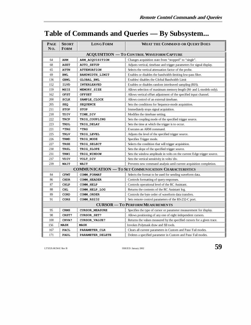
Remote Control Commands and Queries
LTXXX-RCM-E Rev B ISSUED: January 2002 59
Table of Commands and Queries — By Subsystem...PAGE
NO.SHORT
FORM
LONG FORM WHAT THE COMMAND OR QUERY DOES
ACQUISITION — TO CONTROL WAVEFORM CAPTURE
64 ARM ARM_ACQUISITION Changes acquisition state from “stopped” to “single”.
68 ASET AUTO_SETUP Adjusts vertical, timebase and trigger parameters for signal display.
65 ATTN ATTENUATION Selects the vertical attenuation factor of theprobe.
69 BWL BANDWIDTH_LIMIT Enables or disables the bandwidth-limiting low-pass filter.
136 GBWL GLOBAL_BWL Enables/disables theGlobal Bandwidth Limit
152 ILVD INTERLEAVED Enables or disables random interleaved sampling (RIS).
159 MSIZ MEMORY_SIZE Allows selection of maximum memory length (M- and L-models only).
162 OFST OFFSET Allows vertical offset adjustment of the specified input channel.
200 SCLK SAMPLE_CLOCK Allows control of an external timebase.
205 SEQ SEQUENCE Sets the conditions for Sequence-mode acquisition.
211 STOP STOP Immediately stops signal acquisition.
218 TDIV TIME_DIV Modifies the timebase setting.
222 TRCP TRIG_COUPLING Sets the coupling mode of the specified trigger source.
223 TRDL TRIG_DELAY Sets the time at which the trigger is to occur.
221 *TRG *TRG Executes an ARM command.
225 TRLV TRIG_LEVEL Adjusts the level of the specified trigger source.
226 TRMD TRIG_MODE Specifies Trigger mode.
227 TRSE TRIG_SELECT Selects the condition that will trigger acquisition.
230 TRSL TRIG_SLOPE Sets the slope of the specified trigger source.
231 TRWI TRIG_WINDOW Sets thewindowamplitude in volts on the current Edge trigger source.
237 VDIV VOLT_DIV Sets the vertical sensitivity in volts/div.
239 WAIT WAIT Prevents newcommand analysis until current acquisition completion.
COMMUNICATION — TO SET COMMUNICATION CHARACTERISTICS
84 CFMT COMM_FORMAT Selects the format to beused for sending waveform data.
86 CHDR COMM_HEADER Controls formatting of query responses.
87 CHLP COMM_HELP Controls operational level of theRC Assistant.
88 CHL COMM_HELP_LOG Returns the contents of theRC Assistant log.
89 CORD COMM_ORDER Controls the byte order of waveform data transfers.
91 CORS COMM_RS232 Sets remote control parameters of the RS-232-C port.
CURSOR — TO PERFORM MEASUREMENTS
95 CRMS CURSOR_MEASURE Specifies the type of cursor or parameter measurement for display.
98 CRST? CURSOR_SET? Allows positioning of any one of eight independent cursors.
100 CRVA? CURSOR_VALUE? Returns the values measured by the specified cursors for a given trace.
156 MASK MASK Invokes Polymask drawand fill tools.
167 PACL PARAMETER_CLR Clears all current parameters in Custom and Pass/Fail modes.
171 PADL PARAMETER_DELETE Deletes a specified parameter in Custom and Pass/Fail modes.

P A R T T W O : C O M M A N D S
60 ISSUED: January 2002 LTXXX-RCM-E Rev B
PAGE
NO.SHORT
FORM
LONG FORM WHAT THE COMMAND OR QUERY DOES
172 PAST? PARAMETER_STATISTICS? Returns current statistics values for the specified pulse parameter.
173 PAVA? PARAMETER_VALUE? Returns current value(s) of parameter(s) and mask tests.
183 PECS PER_CURSOR_SET Allows positioning of any one of six independent cursors.
185 PECV? PER_CURSOR_VALUE? Returns the values measured by specified cursors for a given trace.
176 PFCO PASS_FAIL_CONDITION Adds a Pass/Fail test condition or custom parameter to display.
178 PFCT PASS_FAIL_COUNTER Resets the Pass/Fail acquisition counters.
179 PFDO PASS_FAIL_DO Defines the desired outcome and actions following a Pass/Fail test.
181 PFMS PASS_FAIL_MASK Generates a tolerancemask around a chosen trace and stores it.
182 PFST? PASS_FAIL_STATUS? Returns the Pass/Fail test for a given line number.
247 XYCO XY_CURSOR_ORIGIN Sets position of origin for absolute cursor measurements on XY display.
248 XYCS XY_CURSOR_SET Allows positioning of any one of six independent XY voltage cursors.
250 XYCV? XY_CURSOR_VALUE? Returns current values of X vs Y cursors.
DISPLAY — TO DISPLAY WAVEFORMS
67 ASCR AUTO_SCROLL Controls theAuto Scroll viewing feature.
74 CHST CALL_HOST Allows manual generation of a service request (SRQ).
80 COLR COLOR Selects color of individual objects such as traces, grids or cursors.
83 CSCH COLOR_SCHEME Selects the display color scheme.
102 DPNT DATA_POINTS Controls display of sample points in single display pixels or bold.
216 DISP DISPLAY Controls the oscilloscope display screen.
116 DTJN DOT_JOIN Controls the interpolation lines between data points.
117 DZOM DUAL_ZOOM Sets horizontal magnification and positioning for all expanded traces.
118 EKEY ENABLE_KEY Allows use of theKEY command in local mode.
125 FATC FAT_CURSOR Controls width of cursors.
134 FSCR FULL_SCREEN Selects magnified viewformat for the grid.
137 GRID GRID Specifies grid display in single, dual or quad mode.
142 HMAG HOR_MAGNIFY Horizontally expands the selected expansion trace.
143 HPOS HOR_POSITION Horizontally positions the intensified zone’s center on the source trace.
151 INTS INTENSITY Sets grid or trace/text intensity level.
154 KEY KEY Displays a string in themenu field.
155 LOGO LOGO Displays LeCroy logo at top of grid.
158 MGAT MEASURE_GATE Controls highlighting of the region between the parameter cursors.
160 MSG MESSAGE Displays a string of characters in the message field.
161 MZOM MULTI_ZOOM Sets horizontal magnification and positioning for all expanded traces.
186 PERS PERSIST Enables or disables the PersistenceDisplay mode.
187 PECL PERSIST_COLOR Controls color rendering method of persistence traces.
188 PELT PERSIST_LAST Shows the last trace drawn in a persistencedata map.
189 PESA PERSIST_SAT Sets the color saturation level in persistence.
190 PESU PERSIST_SETUP Selects display persistenceduration in Persistencemode.
203 SCSV SCREEN_SAVE Controls the automatic screen saver.

Remote Control Commands and Queries
LTXXX-RCM-E Rev B ISSUED: January 2002 61
PAGE
NO.SHORT
FORM
LONG FORM WHAT THE COMMAND OR QUERY DOES
204 SEL SELECT Selects the specified trace for manual display control.
219 TRA TRACE Enables or disables the display of a trace.
220 TOPA TRACE_OPACITY Controls the opacity of the trace color.
235 VMAG VERT_MAGNIFY Vertically expands the specified trace.
236 VPOS VERT_POSITION Adjusts the vertical position of the specified trace.
246 XYAS? XY_ASSIGN? Returns the traces currently assigned to theXY display.
252 XYDS XY_DISPLAY Enables or disables theXY display mode.
253 XYRD XY_RENDER Controls XY plot: smooth or disconnected points.
254 XYSA XY_SATURATION Sets persistence color saturation level in XY display.
FUNCTION — TO PERFORM WAVEFORM MATHEMATICAL OPERATIONS
75 CLM CLEAR_MEMORY Clears the specified memory.
76 CLSW CLEAR_SWEEPS Restarts the cumulative processing functions.
106 DEF DEFINE Specifies themathematical expression to be evaluated by a function.
127 FCR FIND_CTR_RANGE Automatically sets the center and width of a histogram.
135 FRST FUNCTION_RESET Resets a waveform processing function.
HARD COPY — TO PRINT THE CONTENTS OF THE DISPLAY
138 HCSU HARDCOPY_SETUP Configures the hardcopydriver.
141 HCTR HARDCOPY_TRANSMIT Sends a string of unmodified ASCII characters to the hardcopyunit.
202 SCDP SCREEN_DUMP Causes a screen dump to the hardcopydevice.
MASS STORAGE — TO CREATE AND DELETE FILE DIRECTORIES
112 DELF DELETE_FILE Deletes files from the currently selected directory on mass storage.
113 DIR DIRECTORY Creates and deletes file directories on mass-storagedevices.
128 FCRD FORMAT_CARD Formats thememory card.
130 FFLP FORMAT_FLOPPY Formats a floppydisk in theDouble- or High-Density format.
132 FHDD FORMAT_HDD Formats the removable hard disk.
126 FLNM FILENAME Changes the default filenameof any stored trace, setup or hard copy.
MISCELLANEOUS — TO CALIBRATE AND TEST
66 ACAL AUTO_CALIBRATE Enables or disables automatic calibration.
71 BUZZ BUZZER Controls the built-in piezoelectric buzzer.
72 *CAL? *CAL? Performs a complete internal calibration of the oscilloscope.
73 COUT CAL_OUTPUT Sets the type of signal put out at theCAL connector.
103 DATE DATE Changes the date/timeof the oscilloscope’s internal real-time clock.
145 *IDN? *IDN? Used for identification purposes.
164 *OPT? *OPT? Identifies oscilloscope options.
196 ROUT REAR_OUTPUT Sets the type of signal put out at rear BNC connector.
207 SLEEP SLEEP Makes the scope wait before it interprets newcommands
216 TDISP TDISP Changes timedisplay from current to trigger or none.
232 *TST? *TST? Performs an internal self-test.

P A R T T W O : C O M M A N D S
62 ISSUED: January 2002 LTXXX-RCM-E Rev B
PAGE
NO.SHORT
FORM
LONG FORM WHAT THE COMMAND OR QUERY DOES
PROBES — TO USE PROBES
192 PRCA? PROBE_CAL? Performs a complete calibration of the connected current probe.
193 PRDG PROBE_DEGAUSS? Degausses and calibrates the connected current probe.
194 PRNA PROBE_NAME? Gives an identification of the probe connected to the oscilloscope.
SAVE/RECALL SETUP — TO PRESERVE AND RESTORE FRONT PANEL SETTINGS
166 PNSU PANEL_SETUP Complements the *SAV/*RST commands.
195 *RCL *RCL Recalls one of five non-volatile panel setups.
198 RCPN RECALL_PANEL Recalls a front panel setup from mass storage.
199 *RST *RST Initiates a device reset.
201 *SAV *SAV Stores the current state in non-volatile internal memory.
213 STPN STORE_PANEL Stores the complete front panel setup on a mass-storage file.
STATUS — TO OBTAIN STATUS INFORMATION AND SET UP SERVICE REQUESTS
63 ALST? ALL_STATUS? Reads and clears the contents of all (but one) of the status registers.
77 *CLS *CLS Clears all the status data registers.
78 CMR? CMR? Reads and clears the contents of theCoMmand error Register (CMR).
104 DDR? DDR? Reads and clears theDevice-Dependent error Register (DDR).
119 *ESE *ESE Sets the standard Event Status Enable (ESE) register.
120 *ESR? *ESR? Reads and clears the Event Status Register (ESR).
123 EXR? EXR? Reads and clears the EXecution error Register (EXR).
146 INE INE Sets the INternal state changeEnable register (INE).
147 INR? INR? Reads and clears the INternal state changeRegister (INR).
153 IST? IST? Individual STatus reads the current state of IEEE 488.
163 *OPC *OPC Sets to true the OPC bit (0) in the Event Status Register (ESR).
191 *PRE *PRE Sets the PaRallel poll Enable register (PRE).
208 *SRE *SRE Sets the Service Request Enable register (SRE).
209 *STB? *STB? Reads the contents of IEEE 488.
233 URR? URR? Reads and clears the User Request status Register (URR).
238 *WAI *WAI WAIt to continue— required by IEEE 488.
WAVEFORM TRANSFER — TO PRESERVE AND RESTORE WAVEFORMS
149 INSP? INSPECT? Allows acquired waveform parts to be read.
197 REC RECALL Recalls a waveform file from mass storage to internal memories M1–4.
212 STO STORE Stores a trace in one of the internal memories M1–4 or mass storage.
214 STST STORE_SETUP Controls theway in which traces are stored.
215 STTM STORE_TEMPLATE Stores thewaveform template in a mass-storagedevice.
217 TMPL? TEMPLATE? Produces a copyof the template describing a completewaveform.
240 WF WAVEFORM Transfers a waveform from the controller to the oscilloscope.
243 WFSU WAVEFORM_SETUP Specifies amount of waveform data for transmission to controller.
245 WFTX WAVEFORM_TEXT Documents the conditions under which a waveform has been acquired

Remote Control Commands and Queries
LTXXX-RCM-E Rev B ISSUED: January 2002 63
STATUS ALL_STATUS?, ALST?Query
DESCRIPTION TheALL_STATUS? query reads and clears the contents of all statusregisters: STB, ESR, INR, DDR, CMR, EXR and URR except for theMAV bit (bit 6) of the STB register. For an interpretation of thecontents of each register, refer to the appropriate status register.
The query is useful in a complete overviewof the state of yourWaverunner oscilloscope.
QUERY SYNTAX ALl_STatus?
RESPONSE FORMAT ALl_STatus STB,<value>,ESR,<value>,INR,<value>,DDR,<value>,CMR,<value>,EXR,<value>,URR,<value>
<value> : = 0 to 65535
EXAMPLE (GPIB) The following reads the contents of all the status registers:
CMD$=“ALST?”: CALL IBWRT(SCOPE%,CMD$):
CALL IBRD(SCOPE%,RSP$): PRINT RSP$
Response message:
ALSTTB,000000,ESR,000052,INR,000005,DDR,000000,CMR,000004,EXR,000024,URR,000000
RELATED COMMANDS *CLS, CMR?, DDR?, *ESR?, EXR?, *STB?, URR?

P A R T T W O : C O M M A N D S
64 ISSUED: January 2002 LTXXX-RCM-E Rev B
ACQUISITION ARM_ACQUISITION, ARMCommand
DESCRIPTION TheARM_ACQUISITION command enables the signal acquisitionprocess by changing the acquisition state (trigger mode) from“stopped” to “single”.
COMMAND SYNTAX ARM_acquisition
EXAMPLE The following enables signal acquisition:
CMD$=“ARM”: CALL IBWRT(SCOPE%,CMD$)
RELATED COMMANDS STOP, *TRG, TRIG_MODE, WAIT

Remote Control Commands and Queries
LTXXX-RCM-E Rev B ISSUED: January 2002 65
ACQUISITION ATTENUATION, ATTNCommand/Query
DESCRIPTION TheATTENUATION command selects the vertical attenuation factor ofthe probe. Values of 1, 2, 5, 10, 20, 25, 50, 100, 200, 500, 1000 or 10000can be specified.
TheATTENUATION? query returns the attenuation factor of thespecified channel.
COMMAND SYNTAX <channel> : ATTeNuation <attenuation>
<channel> : = C1, C2, C3, C4, EX, EX10<attenuation> : = 1, 2, 5, 10, 20, 25, 50, 100, 200, 500,1000, 10000
QUERY SYNTAX <channel> : ATTeNuation?
RESPONSE FORMAT <channel> : ATTeNuation <attenuation>
AVAILABILITY<channel> : C3, C4 available only on four-channel Waverunneroscilloscopes.
EXAMPLE (GPIB) The following sets to 100 the attenuation factor of Channel 1:
CMD$=“C1:ATTN 100”: CALL IBWRT(SCOPE%,CMD$)

P A R T T W O : C O M M A N D S
66 ISSUED: January 2002 LTXXX-RCM-E Rev B
MISCELLANEOUS AUTO_CALIBRATE, ACALCommand/Query
DESCRIPTION TheAUTO_CALIBRATE command is used to enable or disable theautomatic calibration of your Waverunner oscilloscope. At power-up,auto-calibration is turned ON, i.e. all input channels are periodicallycalibrated for the current input amplifier and timebase settings.
The automatic calibration can be disabled by issuing the commandACAL OFF. Whenever convenient, a *CAL? query may be issued tofully calibrate the oscilloscope. When the oscilloscope is returned tolocal control, the periodic calibrations are resumed.
The response to theAUTO_CALIBRATE? query indicates whetherauto-calibration is enabled.
COMMAND SYNTAX Auto_CALibrate <state>
<state> : = ON, OFF
QUERY SYNTAX Auto_CALibrate?
RESPONSE FORMAT Auto_CALibrate <state>
EXAMPLE (GPIB) The following disables auto-calibration:
CMD$=“ACAL OFF”: CALL IBWRT(SCOPE%,CMD$)
RELATED COMMANDS *CAL?

Remote Control Commands and Queries
LTXXX-RCM-E Rev B ISSUED: January 2002 67
DISPLAY AUTO_SCROLL, ASCRCommand/Query
DESCRIPTION TheAUTO_SCROLL command and query controls the Auto Scrollfeature, accessed through the front panel using the MATH SETUPbutton and ZOOM + MATH menus. This automatically moves theselected trace (or all traces if multi-zoom is on) across the screen. Thecommand turns the scroll on and off and sets the scrolling speed indivisions per second, and the query returns the current scroll rate.
COMMAND SYNTAX Auto_SCRoll <action>,<mode>,<speed>
<action> : = PLAY, REVERSE, STOP
<mode> : = DIV_S, DIV_U
<speed> : = 0.01 to 10.00 for DIV_U mode;0.10 to 10.00 for DIV_S mode.
QUERY SYNTAX Auto_SCRoll?
RESPONSE FORMAT Auto_SCRoll <action>,<mode>,<speed>
EXAMPLE (GPIB) The following activates Auto Scroll and start scrolling the data to theright at a rate of 2 s/div.:
CMD$=“ASCR PLAY,DIV_S,2”: CALL IBWRT(SCOPE%,CMD$)
RELATED COMMANDS MULTI_ZOOM, HOR_MAGNIFY, HOR_POSITION

P A R T T W O : C O M M A N D S
68 ISSUED: January 2002 LTXXX-RCM-E Rev B
ACQUISITION AUTO_SETUP, ASETCommand
DESCRIPTION TheAUTO_SETUP command attempts to display the input signal(s) byadjusting the vertical, timebase and trigger parameters. AUTO-SETUPoperates only on the channels whose traces are currently turned on. If notraces are turned on, AUTO_SETUP operates on all channels and turnson all of the traces.
If signals are detected on several channels, the lowest numberedchannel with a signal determines the selection of the timebase andtrigger source.
If only one input channel is turned on, the timebase will be adjustedfor that channel.
The <channel> : AUTO_SETUP FIND command adjusts gain andoffset only for the specified channel.
COMMAND SYNTAX <channel> : Auto_SETup [FIND]
<channel> : = C1, C2, C3, C4
If the FIND keyword is present, gain and offset adjustments will beperformed only on the specified channel. In this case, if no <channel>prefix is added, then an auto-setup will be performed on the channelused on the last ASET FIND remote command. In the absence of theFIND keyword, the normal auto-setup will be performed, regardless ofthe <channel> prefix.
AVAILABILITY <channel> : = C3, C4 only on four-channel Waverunneroscilloscopes.
EXAMPLE The following instructs the oscilloscope to perform an auto-setup:
CMD$=“ASET”: CALL IBWRT(SCOPE%,CMD$)

Remote Control Commands and Queries
LTXXX-RCM-E Rev B ISSUED: January 2002 69
ACQUISITION BANDWIDTH_LIMIT, BWLCommand/Query
DESCRIPTION BANDWIDTH_LIMIT enables or disables the bandwidth-limiting low-pass filter. When Global_BWL (see page 136) is on, the BWL commandapplies to all channels; when off, the command is used to set thebandwidth individually for each channel. The response to theBANDWIDTH_LIMIT? query indicates whether the bandwidth filtersare on or off.
COMMAND SYNTAX BandWidth_Limit <mode>
Or, alternatively, to choose the bandwidth limit of an individualchannel or channels when Global_BWL is off:
BandWidth_Limit <channel>,<mode>[,<channel>,<mode>
[,<channel>,<mode>[,<channel>,<mode> ]]]
<mode> : = OFF, ON, 200MHZ
<channel> : = C1, C2, C3, C4
QUERY SYNTAX BandWidth_Limit?
RESPONSE FORMAT When Global_BWL is on, or if Global_BWL is off and all four channelshave the same bandwidth limit, the response is:
BandWidth_Limit <mode>
Or, alternatively, if at least two channels have their bandwidth limitfilters set differently from one another, the response is:
BandWidth_Limit <channel>,<mode>[,<channel>,<mode>
[,<channel>,<mode>[,<channel>,<mode> ]]]
AVAILABILITY C3, C4 : Available only on four-channel models.
EXAMPLE The following turns on the bandwidth filter for all channels, whenGlobal_BWL is on (as it is by default):
CMD$=“BWL ON”: CALL IBWRT(SCOPE%,CMD$)

P A R T T W O : C O M M A N D S
70 ISSUED: January 2002 LTXXX-RCM-E Rev B
The following turns the bandwidth filter on for Channel 1 only (the firstturns off Global_BWL):
CMD$=“GBWL OFF”: CALL IBWRT(SCOPE%,CMD$)
CMD$=“BWL C1,ON”: CALL IBWRT(SCOPE%,CMD$)
CMD$=“GBWL OFF”: CALL IBWRT(SCOPE%,CMD$)
CMD$=“BWL C1,ON”: CALL IBWRT(SCOPE%,CMD$)
RELATED COMMANDS GLOBAL_BWL

Remote Control Commands and Queries
LTXXX-RCM-E Rev B ISSUED: January 2002 71
MISCELLANEOUS BUZZER, BUZZCommand
TheBUZZER command controls the built-in piezo-electric buzzer.This is useful for attracting the attention of a local operator in aninteractive working application. The buzzer can either be activated forshort beeps (about 400 ms long in BEEP mode) or continuously for acertain time interval you select by turning the buzzer ON or OFF.
DESCRIPTION
NN OOTTEE :: This command is only able to be used in oscilloscopesfitted with the CLBZ hard option.
COMMAND SYNTAX BUZZer <state>
<state> : = BEEP, ON, OFF
EXAMPLE (GPIB) Sending the following will cause the oscilloscope to sound two shorttones.
CMD$=“BUZZ BEEP;BUZZ BEEP”:
CALL IBWRT(SCOPE%,CMD$)

P A R T T W O : C O M M A N D S
72 ISSUED: January 2002 LTXXX-RCM-E Rev B
MISCELLANEOUS *CAL?Query
DESCRIPTION The*CAL? query causes the oscilloscope to perform an internal self-calibration and generates a response that indicates whether or not yourWaverunner oscilloscope completed the calibration without error. Thisinternal calibration sequence is the same as that which occurs at power-up. At the end of the calibration, after the response has indicated howthe calibration terminated, the oscilloscope returns to the state it was injust prior to the calibration cycle.
QUERY SYNTAX *CAL?
RESPONSE FORMAT *CAL <diagnostics>
<diagnostics> : = 0 or other
0 = Calibration successful
EXAMPLE (GPIB) The following forces a self-calibration:
CMD$=“*CAL?”: CALL IBWRT(SCOPE%,CMD$):
CALL IBRD(SCOPE%,RD$): PRINT RD$
Response message (if no failure): *CAL 0
RELATED COMMANDS AUTO_CALIBRATE

Remote Control Commands and Queries
LTXXX-RCM-E Rev B ISSUED: January 2002 73
MISCELLANEOUS CAL_OUTPUT, COUTCommand/Query
DESCRIPTION TheCAL_OUTPUT command is used to set the type of signal put out atthe Waverunner front panel CAL connector.
COMMAND SYNTAX Cal_OUTput <mode>[,<level>[,<rate>]]
<mode> : = CALSQ, LEVEL
< level> : = −1.0 to 1.00 V into 1 MΩ<rate> : = 500 Hz to 1 MHz.
QUERY SYNTAX Cal_OUTput?
RESPONSE FORMAT Cal_OUTput <mode>,<level>[,<rate>]
EXAMPLE (GPIB) The following sets the calibration signal to give a 0–0.2 volt pulse of25 ns width at a 10 kHz rate:
CMD$=“COUT PULSE,0.2 V,10 kHz”:
CALL IBWRT(SCOPE%,CMD$)
ADDITIONAL INFORMATION
NOTATION
CALSQ Provides a square signal
LEVEL Provides a DC signal at the requested level

P A R T T W O : C O M M A N D S
74 ISSUED: January 2002 LTXXX-RCM-E Rev B
DISPLAY CALL_HOST, CHSTCommand/Query
DESCRIPTION TheCALL_HOST command allows you to manually generate a servicerequest (SRQ). Once the CALL_HOST command has been received,the message “Call Host” will be displayed next to the lowest button onthe menu-button column immediately next to the screen. Pressing thisbutton while in the root menu sets the User Request status Register(URR) and the URQ bit of the Event Status Register. This can generatea SRQ in local mode, provided the service request mechanism has beenenabled.
The response to theCALL_HOST? query indicates whether CALLHOST is enabled (on) or disabled (off).
COMMAND SYNTAX Call_HoST <state>
<state> : = ON, OFF
QUERY SYNTAX Call_HoST?
RESPONSE FORMAT Call_HoST <state>
EXAMPLE (GPIB) After executing the following an SRQ request will be generatedwhenever the button is pressed (it is assumed that SRQ servicing hasalready been enabled):
CMD$=“CHST ON”: CALL IBWRT(SCOPE%,CMD$)
RELATED COMMANDS URR

Remote Control Commands and Queries
LTXXX-RCM-E Rev B ISSUED: January 2002 75
FUNCTION CLEAR_MEMORY, CLMCommand
DESCRIPTION TheCLEAR_MEMORY command clears the specified memory. Datapreviously stored in this memory are erased and memory space isreturned to the free memory pool.
COMMAND SYNTAX CLear_Memory < memory>
<memory> : = M1, M2, M3, M4
EXAMPLE (GPIB) The following clears the memory M2.
CMD$=“CLM M2”: CALL IBWRT(SCOPE%,CMD$)
RELATED COMMANDS STORE

P A R T T W O : C O M M A N D S
76 ISSUED: January 2002 LTXXX-RCM-E Rev B
FUNCTION CLEAR_SWEEPS, CLSWCommand
DESCRIPTION TheCLEAR_SWEEPS command restarts the cumulative processingfunctions: summed or continuous average, extrema, FFT poweraverage, histogram, pulse parameter statistics, Pass/Fail counters, andpersistence.
COMMAND SYNTAX CLear SWeeps
EXAMPLE (GPIB) The following example will restart the cumulative processing:
CMD$=“CLSW”: CALL IBWRT(SCOPE%,CMD$)
RELATED COMMANDS DEFINE, INR

Remote Control Commands and Queries
LTXXX-RCM-E Rev B ISSUED: January 2002 77
STATUS *CLSCommand
DESCRIPTION The*CLS command clears all status data registers.
COMMAND SYNTAX *CLS
EXAMPLE (GPIB) The following causes all the status data registers to be cleared:
CMD$=“*CLS”: CALL IBWRT(SCOPE%,CMD$)
RELATED COMMANDS ALL_STATUS, CMR, DDR, *ESR, EXR, *STB, URR

P A R T T W O : C O M M A N D S
78 ISSUED: January 2002 LTXXX-RCM-E Rev B
STATUS CMR?Query
DESCRIPTION TheCMR? query reads and clears the contents of the CoMmand errorRegister (CMR) — see table next page — which specifies the last syntaxerror type detected by your Waverunner oscilloscope.
QUERY SYNTAX CMR?
RESPONSE FORMAT CMR <value><value> : = 0 to 13
EXAMPLE (GPIB) The following reads the contents of the CMR register:
CMD$=“CMR?”: CALL IBWRT(SCOPE%,CMD$):
CALL IBRD(SCOPE%,RSP$): PRINT RSP$
RELATED COMMANDS ALL_STATUS?, *CLS

Remote Control Commands and Queries
LTXXX-RCM-E Rev B ISSUED: January 2002 79
ADDITIONAL INFORMATION
COMMAND ERROR STATUS REGISTER STRUCTURE (CMR)
Value Description
1 Unrecognized command/query header
2 Illegal header path
3 Illegal number
4 Illegal number suffix
5 Unrecognized keyword
6 String error
7 GET embedded in another message
10 Arbitrary data block expected
11 Non-digit character in byte count field of arbitrary data block
12 EOI detected during definite length data block transfer
13 Extra bytes detected during definite length data block transfer

P A R T T W O : C O M M A N D S
80 ISSUED: January 2002 LTXXX-RCM-E Rev B
DISPLAY COLOR, COLRCommand/Query
DESCRIPTION TheCOLOR command is used to select the color of an individualdisplay object such as text, trace, grid or cursor.
The response to the COLOR? query indicates the color assigned toeach display object, whether or not it is currently displayed.
NN OOTTEE :: This command is only effective if the color scheme(CSCH) is chosen from the user schemes U1, U2, U3 or U4.
COMMAND SYNTAX COLoR <object, color>[,...<object>,<color>]
<object> : = BACKGND, C1, C2, C3, C4, TA, TB, TC, TD, GRID,TEXT, CURSOR, NEUTRAL, WARNING ,
<color> : = WHITE, CYAN, YELLOW, GREEN, MAGENTA,BLUE, RED, LTGRAY, GRAY, SLGRAY, CHGRAY, DKCYAN,CREAM, SAND, AMBER, OLIVE, LTGEEN, JADE, LMGREEN,APGREEN, EMGREEN, GRGREEN, OCSPRAY, ICEBLUE,PASTBLUE, PALEBLUE, SKYBLUE, ROYLBLUE, DEEPBLUE,NAVY, PLUM, PURPLE, AMETHYST, FUCHSIA, RASPBRY,NEONPINK, PALEPINK, PINK, VERMIL, ORANGE, CERISE,KHAKI, BROWN, BLACK
QUERY SYNTAX COLoR?
RESPONSE FORMAT COLoR <object>,<color>[,...<object>,<color>]
EXAMPLE (GPIB) The following selects color scheme U1, and then red as the color ofChannel 1:
CMD$=“CSCH U1”: CALL IBWRT(SCOPE%,CMD$)CMD$=“COLR C1,RED”: CALL IBWRT(SCOPE%,CMD$)
RELATED COMMANDS COLOR_SCHEME, PERSIST_COLOR

Remote Control Commands and Queries
LTXXX-RCM-E Rev B ISSUED: January 2002 81
ADDITIONAL INFORMATION
NOTATION
<color> Color <color> Color
WHITE White OCSPRAY Ocean Spray
CYAN Cyan ICEBLUE Ice Blue
YELLOW Yellow PASTBLUE Pastel Blue
GREEN Green PALEBLUE Pale Blue
MAGENTA Magenta SKYBLUE Sky Blue
BLUE Blue ROYLBLUE Royal Blue
RED Red DEEPBLUE Deep Blue
LTGRAY Light Gray NAVY Navy
GRAY Gray PLUM Plum
SLGRAY Slate Gray PURPLE Purple
CHGRAY Charcoal Gray AMETHYST Amethyst
DKCYAN Dark Cyan FUCHSIA Fuchsia
CREAM Cream RASPB Raspberry
SAND Sand NEONPINK Neon Pink
AMBER Amber PALEPINK Pale Pink
OLIVE Olive PINK Pink
LTGREEN Light Green VERMIL Vermilion
JADE Jade ORANGE Orange
LMGREEN Lime Green CERISE Cerise
APGREEN Apple Green KHAKI Khaki

P A R T T W O : C O M M A N D S
82 ISSUED: January 2002 LTXXX-RCM-E Rev B
EMGREEN Emerald Green BROWN Brown
GRGREEN Grass Green BLACK Black
<object> Display Object <object> Display Object
BACKGND Background CURSOR cursors
C1..C4 Channel Traces WARNING Warning Messages
TA..TD Function Traces NEUTRAL Neutral color
GRID Grid lines OVERLAYSMenu background colorin FULL SCREEN

Remote Control Commands and Queries
LTXXX-RCM-E Rev B ISSUED: January 2002 83
DISPLAY COLOR_SCHEME, CSCHCommand/Query
DESCRIPTION TheCOLOR_SCHEME command is used to select the color scheme forthe display.
The response to theCOLOR_SCHEME? query indicates the colorscheme in use.
COMMAND SYNTAX Color_SCHeme <scheme>
<scheme > : = 1, 2, 3, 4, 5, 6, 7, U1, U2, U3, U4
QUERY SYNTAX Color_SCHeme?
RESPONSE FORMAT Color_SCHeme <scheme>
EXAMPLE (GPIB) The following selects the user color scheme U2:
CMD$=“CSCH U2”: CALL IBWRT(SCOPE%,CMD$)
RELATED COMMANDS COLOR, PERSIST_COLOR
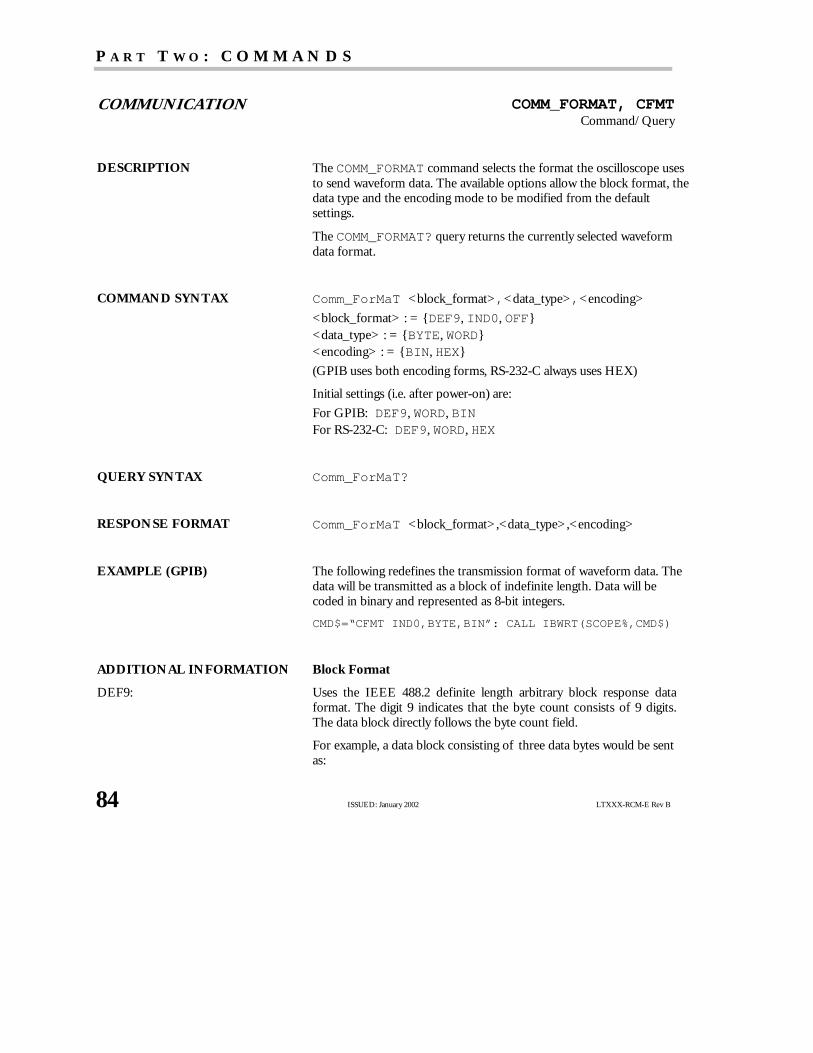
P A R T T W O : C O M M A N D S
84 ISSUED: January 2002 LTXXX-RCM-E Rev B
COMMUNICATION COMM_FORMAT, CFMTCommand/Query
DESCRIPTION TheCOMM_FORMAT command selects the format the oscilloscope usesto send waveform data. The available options allow the block format, thedata type and the encoding mode to be modified from the defaultsettings.
TheCOMM_FORMAT? query returns the currently selected waveformdata format.
COMMAND SYNTAX Comm_ForMaT <block_format>,<data_type>,<encoding>
<block_format> : = DEF9, IND0, OFF<data_type> : = BYTE, WORD<encoding> : = BIN, HEX
(GPIB uses both encoding forms, RS-232-C always uses HEX)
Initial settings (i.e. after power-on) are:
For GPIB: DEF9, WORD, BINFor RS-232-C: DEF9, WORD, HEX
QUERY SYNTAX Comm_ForMaT?
RESPONSE FORMAT Comm_ForMaT <block_format> ,<data_type>,<encoding>
EXAMPLE (GPIB) The following redefines the transmission format of waveform data. Thedata will be transmitted as a block of indefinite length. Data will becoded in binary and represented as 8-bit integers.
CMD$=“CFMT IND0,BYTE,BIN”: CALL IBWRT(SCOPE%,CMD$)
ADDITIONAL INFORMATION Block Format
DEF9: Uses the IEEE 488.2 definite length arbitrary block response dataformat. The digit 9 indicates that the byte count consists of 9 digits.The data block directly follows the byte count field.
For example, a data block consisting of three data bytes would be sentas:

Remote Control Commands and Queries
LTXXX-RCM-E Rev B ISSUED: January 2002 85
WF DAT1,#9000000003<DAB><DAB><DAB>
where <DAB> represents an eight-bit binary data byte.
IND0: Uses the IEEE 488.2 indefinite length arbitrary block response dataformat.
A <NL^END> (newline with EOI) signifies that block transmissionhas ended.
The same data bytes as above would be sent as:
WF DAT1,#0<DAB><DAB><DAB><NL^END>
OFF: Same as IND0. In addition, the data block type identifier and theleading # 0 of the indefinite length block will be suppressed. The datapresented above would be sent as:
WF <DAB><DAB><DAB><NL^END>
NN OOTTEE :: The format OFF does not conform to the IEEE 488.2standard and is only provided for special applications where theabsolute minimum of data transfer may be important.
Data Type
BYTE: Transmits the waveform data as eight-bit signed integers (one byte).
WORD: Transmits the waveform data as 16-bit signed integers (two bytes).
NN OOTTEE :: The data type BYTE transmits only the high-order bitsof the internal 16-bit representation. The precision contained inthe low-order bits is lost.
Encoding
BIN: Binary encoding (GPIB only)
HEX: Hexadecimal encoding (bytes are converted to 2 hexadecimal ASCIIdigits (0, ...9, A, ...F))
RELATED COMMANDS WAVEFORM

P A R T T W O : C O M M A N D S
86 ISSUED: January 2002 LTXXX-RCM-E Rev B
COMMUNICATION COMM_HEADER, CHDRCommand/Query
DESCRIPTION TheCOMM_HEADER command controls the way the oscilloscopeformats responses to queries. There are three response formats:LONG, in which responses start with the long form of the headerword; SHORT, where responses start with the short form of theheader word; and OFF, for which headers are omitted from theresponse and suffix units in numbers are suppressed.
Unless you request otherwise, the SHORT response format is used.
This command does not affect the interpretation of messages sentto the oscilloscope. Headers can be sent in their long or shortform regardless of theCOMM_HEADER setting.
NN OOTTEE :: The default format, i.e.that just after power-on, is SHORT.
Querying the vertical sensitivity of Channel 1 may result in one ofthe following responses:
COMM_HEADER RESPONSE
LONG C1:VOLT_DIV 200E-3 V
SHORT C1:VDIV 200E-3 V
OFF 200E-3
COMMAND SYNTAX Comm_HeaDeR <mode>
<mode> : = SHORT, LONG, OFF
QUERY SYNTAX Comm_HeaDeR?
RESPONSE FORMAT Comm_HeaDeR <mode>
EXAMPLE (GPIB) The following code sets the response header format to SHORT:
CMD$=“CHDR SHORT”: CALL IBWRT(SCOPE%,CMD$)
RELATED COMMANDS COMM_HELP_LOG
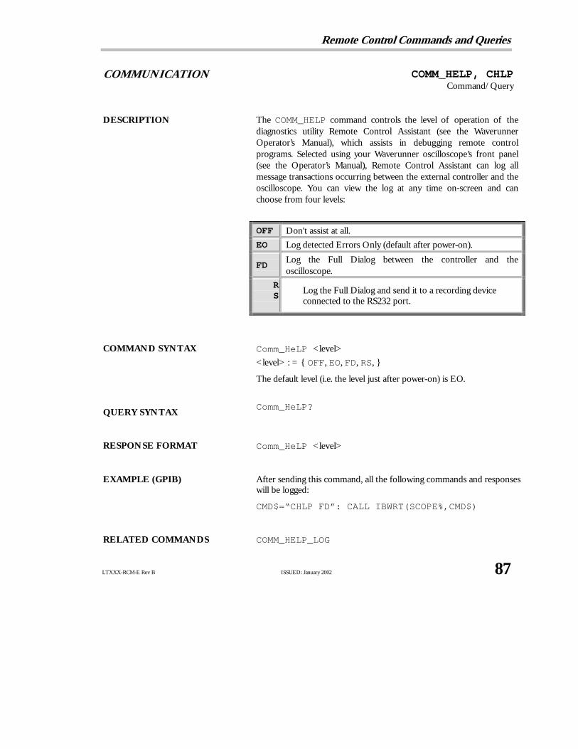
Remote Control Commands and Queries
LTXXX-RCM-E Rev B ISSUED: January 2002 87
COMMUNICATION COMM_HELP, CHLPCommand/Query
DESCRIPTION The COMM_HELP command controls the level of operation of thediagnostics utility Remote Control Assistant (see the WaverunnerOperator’s Manual), which assists in debugging remote controlprograms. Selected using your Waverunner oscilloscope’s front panel(see the Operator’s Manual), Remote Control Assistant can log allmessage transactions occurring between the external controller and theoscilloscope. You can view the log at any time on-screen and canchoose from four levels:
OFF Don't assist at all.
EO Log detected Errors Only (default after power-on).
FDLog the Full Dialog between the controller and theoscilloscope.
RS
Log the Full Dialog and send it to a recording deviceconnected to the RS232 port.
COMMAND SYNTAX Comm_HeLP <level>
<level> : = OFF, EO, FD, RS,
The default level (i.e. the level just after power-on) is EO.
QUERY SYNTAXComm_HeLP?
RESPONSE FORMAT Comm_HeLP <level>
EXAMPLE (GPIB) After sending this command, all the following commands and responseswill be logged:
CMD$=“CHLP FD”: CALL IBWRT(SCOPE%,CMD$)
RELATED COMMANDS COMM_HELP_LOG

P A R T T W O : C O M M A N D S
88 ISSUED: January 2002 LTXXX-RCM-E Rev B
COMMUNICATION COMM_HELP_LOG?, CHL?Query
DESCRIPTION TheCOMM_HELP_LOG query returns the current contents of the loggenerated by the Remote Control Assistant (seeCHLP description). Ifthe optional parameter CLR is specified, the log will be cleared after thetransmission. Otherwise, it will be kept.
QUERY SYNTAX Comm_HeLP_Log? [CLR]
RESPONSE FORMAT Comm_Help_Log <string containing the logged text>
EXAMPLE (GPIB) The following reads the remote control log and prints it:
CMD$=“CHL?”: CALL IBWRT(SCOPE%,CMD$)PRINT
RELATED COMMANDS COMM_HELP

Remote Control Commands and Queries
LTXXX-RCM-E Rev B ISSUED: January 2002 89
COMMUNICATION COMM_ORDER, CORDCommand/Query
DESCRIPTION TheCOMM_ORDER command controls the byte order of waveformdata transfers. Waveform data can be sent with the most significant byte(MSB) or the least significant byte (LSB) in the first position. Thedefault mode is to send the MSB first. COMM_ORDER applies equally tothe waveform’s descriptor and time blocks. In the descriptor somevalues are 16 bits long (“word”), 32 bits long (“long” or “float”), or 64bits long (“double”). In the time block all values are floating values, i.e.32 bits long. When COMM_ORDER HI is specified, the MSB is sentfirst; when COMM_ORDER LO is specified, the LSB is sent first.
TheCOMM_ORDER? query returns the byte transmission order incurrent use.
COMMAND SYNTAX Comm_ORDer <mode>
<mode> : = HI, LO
NN OOTTEE :: The initial mode, i.e. the mode after power-on, is HI.
QUERY SYNTAX Comm_ORDer?
RESPONSE FORMAT Comm_ORDer <mode>
EXAMPLE The order of transmission of waveform data depends on the data type.The following table illustrates the different possibilities:

P A R T T W O : C O M M A N D S
90 ISSUED: January 2002 LTXXX-RCM-E Rev B
TYPE CORD HI CORD LO
Word <MSB><LSB> <LSB><MSB>
Long or Float <MSB><byte2><byte3><LSB> <LSB><byte3><byte2><MSB>
Double <MSB><byte2>...<byte7><LSB> <LSB><byte7>...<byte2><MSB>
RELATED COMMANDS WAVEFORM

Remote Control Commands and Queries
LTXXX-RCM-E Rev B ISSUED: January 2002 91
COMMUNICATION COMM_RS232, CORSCommand/Query
DESCRIPTION TheCOMM_RS232 command sets the parameters of the RS-232-Cport for remote control.
TheCOMM_RS232? query reports the settings of the parameters.
NN OOTTEE :: This command and query is only valid when you controlthe oscilloscope remotely using the Waverunner RS-232-C port.
PARAMETERS
End Input character: When received by the oscilloscope, this character is interpreted as theEND-of-a-command message marker. The commands received willbe parsed and executed.
End Output string: The oscilloscope adds this string at the end of a response message.When the host computer receives this string, it knows that theoscilloscope has completed its response.
Line Length: This parameter defines the maximum number of characters sent to thehost in a single line. Remaining characters of the response are outputin separate additional lines. This parameter is only applicable if a lineseparator has been selected.
Line Separator: This parameter is used to select the line-splitting mechanism and todefine the characters used to split the oscilloscope response messagesinto many lines. Possible line separators are: CR, LF, CRLF. <CR>,<LF> or <CR> followed by <LF>. These are sent to the hostcomputer after <line_length> characters.
SRQ string: This string is sent each time the oscilloscope signals an SRQ to thehost computer.
Some COMM_RS232 parameters require ASCII strings as actualarguments. In order to facilitate theembeddingof non-printable charactersinto such strings, escape sequences can be used. The back-slash character(‘\’) is used as an escape character. The following escape sequences arerecognized:
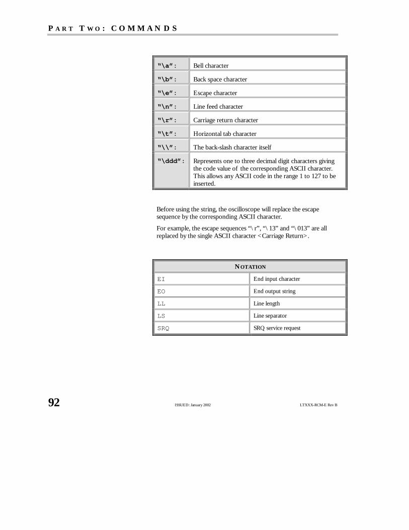
P A R T T W O : C O M M A N D S
92 ISSUED: January 2002 LTXXX-RCM-E Rev B
“\a”: Bell character
“\b”: Back space character
“\e”: Escape character
“\n”: Line feed character
“\r”: Carriage return character
“\t”: Horizontal tab character
“\\”: The back-slash character itself
“\ddd”: Represents one to three decimal digit characters givingthe code value of the corresponding ASCII character.This allows any ASCII code in the range 1 to 127 to beinserted.
Before using the string, the oscilloscope will replace the escapesequence by the corresponding ASCII character.
For example, the escape sequences “\r”, “\13” and “\013” are allreplaced by the single ASCII character <Carriage Return>.
NOTATION
EI End input character
EO End output string
LL Line length
LS Line separator
SRQ SRQ service request

Remote Control Commands and Queries
LTXXX-RCM-E Rev B ISSUED: January 2002 93
COMMAND SYNTAX COmm_RS232 EI,<ei_char>,EO,‘<eo_string>’,LL,<line_length>,LS,<Line_sep>,SRQ,‘<srq_string>’
<ei_char> : = 1 to 126 (default: 13 = Carriage Return)
<eo_string> : = A non-empty ASCII string of up to 20 characters(default: “\n\r”)
<line_length> : = 40 to 1024 (default: 256)
<line_sep> : = OFF, CR, LF, CRLF (default: OFF)
<srq_string> : = An ASCII string of up to 20 characters which maybe empty (default: empty string)
QUERY SYNTAX COmm_RS232?
RESPONSE FORMAT COmm_RS232 EI,<ei_char>,EO,“p <eo_string>”,LL,<line_length>,LS,<line_sep>,SRQ,“<srq_string>”
EXAMPLE After executing the command
COMM_RS232 EI,3,EO, “\r\nEND\r\n”
the oscilloscope will assume that it has received a complete messageeach time the <ETX> (decimal value 3) is detected. Responsemessages will be terminated by sending the character sequence“<CR><LF>END<CR><LF>”.

P A R T T W O : C O M M A N D S
94 ISSUED: January 2002 LTXXX-RCM-E Rev B
ACQUISITION COUPLING, CPLCommand/Query
DESCRIPTION The COUPLING command selects the coupling mode of thespecified input channel.
The COUPLING? query returns the coupling mode of the specifiedchannel.
COMMAND SYNTAX <channel> : CouPLing <coupling>
<channel> : = C1, C2, C3, C4, EX, EX10
<coupling> : = A1M, D1M, D50, GND
QUERY SYNTAX <channel> : CouPLing?
RESPONSE FORMAT <channel> : CouPLing <coupling>
<coupling> : = A1M, D1M, D50, GND, OVL
<coupling> : OVL is returned in the event of signal overload while inDC 50 Ω coupling. In this condition, the oscilloscope will disconnectthe input.
AVAILABILITY<channel> : = C3, C4 only on four-channel Waverunneroscilloscopes.
EXAMPLE (GPIB) The following sets the coupling of Channel 2 to 50 Ω DC:
CMD$=“C2:CPL D50”: CALL IBWRT(SCOPE%,CMD$)
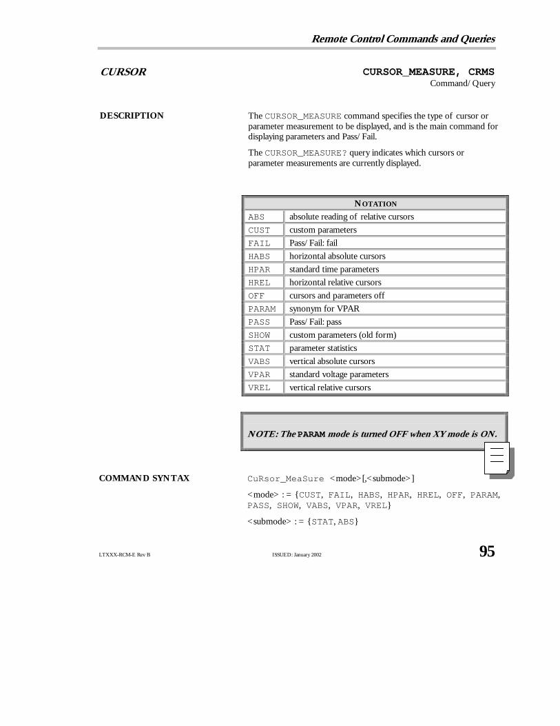
Remote Control Commands and Queries
LTXXX-RCM-E Rev B ISSUED: January 2002 95
CURSOR CURSOR_MEASURE, CRMSCommand/Query
DESCRIPTION TheCURSOR_MEASURE command specifies the type of cursor orparameter measurement to be displayed, and is the main command fordisplaying parameters and Pass/Fail.
TheCURSOR_MEASURE? query indicates which cursors orparameter measurements are currently displayed.
NOTATION
ABS absolute reading of relative cursors
CUST custom parameters
FAIL Pass/Fail: fail
HABS horizontal absolute cursors
HPAR standard time parameters
HREL horizontal relative cursors
OFF cursors and parameters off
PARAM synonym for VPAR
PASS Pass/Fail: pass
SHOW custom parameters (old form)
STAT parameter statistics
VABS vertical absolute cursors
VPAR standard voltage parameters
VREL vertical relative cursors
NN OOTTEE :: The PARAM mode is turned OFF when XY mode is ON.
COMMAND SYNTAX CuRsor_MeaSure <mode>[,<submode>]
<mode> : = CUST, FAIL, HABS, HPAR, HREL, OFF, PARAM,PASS, SHOW, VABS, VPAR, VREL
<submode> : = STAT, ABS

P A R T T W O : C O M M A N D S
96 ISSUED: January 2002 LTXXX-RCM-E Rev B
NN OOTTEE :: The keyword STAT is optional with modes CUST, HPAR, and VPAR. If present, STAT turnsparameter statistics on. Absence of STAT turns parameter statistics off.
The keyword ABS is optional with mode HREL. If it is present, ABS chooses absolute amplitudereading of relative cursors. Absence of ABS selects relative amplitude reading of relative cursors.
QUERY SYNTAX CuRsor_MeaSure?
RESPONSE FORMAT CuRsor_MeaSure <mode>
EXAMPLE (GPIB) The following switches on the vertical relative cursors:
CMD$=“CRMS VREL”: CALL IBWRT(SCOPE%,CMD$)
The following determines which cursor is currently turned on:
CMDS$=“CRMS?”: CALL IBWRT(SCOPE%,CMD$):
CALL IBRD(SCOPE%,RD$): PRINT RD$
Example of response message:
CRMS OFF
RELATED COMMANDS CURSOR_SET, PARAMETER_STATISTICS,PARAMETER_VALUE, PASS_FAIL_CLEAR,PASS_FAIL_CONDITION, PASS_FAIL_DELETE,PASS_FAIL_MASK,
ADDITIONAL INFORMATION To turn off the cursors, parameter measurements or Pass/Fail tests,use:
CURSOR_MEASURE OFF
To turn on a cursor display, use one of these four forms:
CURSOR_MEASURE HABS
CURSOR_MEASURE HREL
CURSOR_MEASURE VABS
CURSOR_MEASURE VREL

Remote Control Commands and Queries
LTXXX-RCM-E Rev B ISSUED: January 2002 97
To turn on a cursor display, use one of these four forms:
CURSOR_MEASURE HABS
CURSOR_MEASURE HREL
CURSOR_MEASURE VABS
CURSOR_MEASURE VREL
CURSOR_MEASURE FAIL
To select parameters in the Custom mode, and to modify the testconditions in the Pass/Fail mode, use the command:
PASS_FAIL_CONDITION

P A R T T W O : C O M M A N D S
98 ISSUED: January 2002 LTXXX-RCM-E Rev B
CURSOR CURSOR_SET, CRSTCommand/Query
DESCRIPTION The CURSOR_SET command allows you to position any one of theeight independent cursors at a given screen location. The positionsof the cursors can be modified or queried even if the required cursoris not currently displayed on the screen.
When setting a cursor position, a trace must be specified, relative towhich the cursor will be positioned.
NN OOTTEE :: If the parameter display is turned on (or the Pass/Faildisplay or the extended parameters display), the parameters ofthe specified trace will be shown unless the newly chosen traceis not displayed or has been acquired in sequence mode; theseconditions will produce an environment error (see table onpage 124). To change only the trace without repositioning thecursors, the CURSOR_SET command can be given with noargument (for example, TB:CRST).
The CURSOR_SET? query indicates the current position ofthe cursor(s). The values returned depend on the grid type selected.
NOTATION
HABS horizontal absolute PREF parameter reference
HDIF horizontal difference VABS vertical absolute
HREF horizontal reference VDIF vertical difference
PDIF parameter difference VREF vertical reference
COMMAND SYNTAX <trace> : CuRsor_SeT <cursor>,<position>[,<cursor>,<position>,<cursor> ,<position>]
<trace> : = TA, TB, TC, TD, C1, C2, C3,C4
<cursor> : = HABS, VABS, HREF, HDIF, VREF, VDIF,PREF, PDIF
<position> : = 0 to 10 DIV (horizontal)

Remote Control Commands and Queries
LTXXX-RCM-E Rev B ISSUED: January 2002 99
<position> : = −29.5 to 29.5 DIV (vertical)
NN OOTTEE :: Parameters are grouped in pairs. The first parameter specifies the cursor to be modified andthe second one indicates its new value. Parameters can be grouped in any order and restricted tothose items to be changed.
The suffixDIV is optional.
QUERY SYNTAX <trace> : CuRsor_SeT? [<cursor> ,...<cursor>]
<cursor> : = HABS, VABS, HREF, HDIF, VREF, VDIF,PREF, PDIF, ALL
RESPONSE FORMAT <trace> : CuRsor_SeT<cursor>,<position> [,<cursor>,<position>,...<cursor>,<position> ]
If <cursor> is not specified, ALL will be assumed. If the position ofa cursor cannot be determined in a particular situation, its positionwill be indicated as UNDEF.
AVAILABILITY <trace> : C3, C4 available only on four-channel oscilloscopes.
EXAMPLE (GPIB) The following positions the VREF and VDIF cursors at +3 DIV and−7 DIV respectively, using Trace A as a reference:
CMD$=“TA:CRST VREF,3DIV,VDIF,−7DIV”:
CALL IBWRT(SCOPE%,CMD$)
RELATED COMMANDS CURSOR_MEASURE, CURSOR VALUE,PARAMETER_VALUE, PER_CURSOR_SET,XY_CURSOR_SET
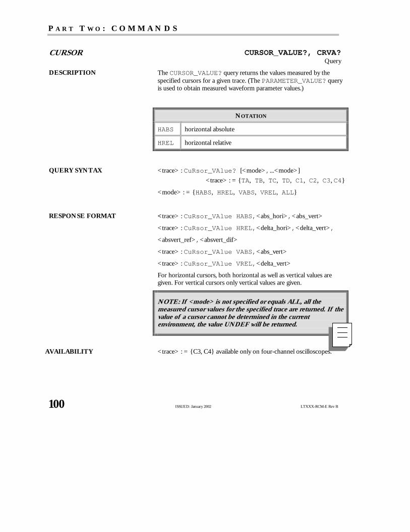
P A R T T W O : C O M M A N D S
100 ISSUED: January 2002 LTXXX-RCM-E Rev B
CURSOR CURSOR_VALUE?, CRVA?Query
DESCRIPTION TheCURSOR_VALUE? query returns the values measured by thespecified cursors for a given trace. (ThePARAMETER_VALUE? queryis used to obtain measured waveform parameter values.)
NOTATION
HABS horizontal absolute
HREL horizontal relative
QUERY SYNTAX <trace> : CuRsor_VAlue? [<mode>,...<mode>]
<trace> : = TA, TB, TC, TD, C1, C2, C3, C4
<mode> : = HABS, HREL, VABS, VREL, ALL
RESPONSE FORMAT < trace> : CuRsor_VAlue HABS,<abs_hori>,<abs_vert>
<trace> : CuRsor_VAlue HREL,<delta_hori>,<delta_vert>,
<absvert_ref>,<absvert_dif>
<trace> : CuRsor_VAlue VABS,<abs_vert>
<trace> : CuRsor_VAlue VREL,<delta_vert>
For horizontal cursors, both horizontal as well as vertical values aregiven. For vertical cursors only vertical values are given.
NN OOTTEE :: If <mode> is not specified or equals ALL, all themeasured cursor values for the specified trace are returned. If thevalue of a cursor cannot be determined in the currentenvironment, the value UNDEF will be returned.
AVAILABILITY <trace> : = C3, C4 available only on four-channel oscilloscopes.

Remote Control Commands and Queries
LTXXX-RCM-E Rev B ISSUED: January 2002 101
EXAMPLE (GPIB) The following query reads the measured absolute horizontal value ofthe cross-hair cursor (HABS) on Channel 2:
CMD$=“C2:CRVA? HABS”: CALL IBWRT(SCOPE%,CMD$):
CALL IBRD(SCOPE%,RSP$): PRINT RSP$
Response message:
C2:CRVA HABS,34.2E−6 S, 244 E−3 V
RELATED COMMANDS CURSOR_SET, PARAMETER_VALUE, PER_CURSOR_VALUE,XY_CURSOR_VALUE
P A R T T W O : C O M M A N D S
102 ISSUED: January 2002 LTXXX-RCM-E Rev B
DISPLAY DATA_POINTS, DPNTCommand/Query
DESCRIPTION TheDATA_POINTS command is used to control whether thewaveform sample points are shown as single display pixels or aremade bold.
The response to theDATA_POINTS? query indicates whether thewaveform sample points are being displayed as single display pixels orin bold face.
COMMAND SYNTAX Data_PoiNTs <state>
<state> : = NORMAL, BOLD
QUERY SYNTAX Data_PoiNTs?
RESPONSE FORMAT Data_PoiNTs <state>
EXAMPLE (GPIB) The following highlights the waveform sample points:
CMD$=“DPNT BOLD”: CALL IBWRT(SCOPE%,CMD$)

Remote Control Commands and Queries
LTXXX-RCM-E Rev B ISSUED: January 2002 103
MISCELLANEOUS DATECommand/Query
DESCRIPTION TheDATE command changes the date/ time of the oscilloscope’sinternal real-time clock.
TheDATE? query returns the current date/ time setting.
COMMAND SYNTAX DATE <day>,<month>,<year>,<hour>,<minute>,<second>
<day> : = 1 to 31
<month> : = JAN, FEB, MAR, APR, MAY, JUN, JUL, AUG, SEP,OCT, NOV, DEC
<year> : = 1990 to 2089
<hour> : = 0 to 23
<minute> : = 0 to 59
<second> : = 0 to 59
TTIIPP:: You need only specify those DATE parameters up to andincluding the parameter to be changed in order to change theyear setting: day, month and year. The time settings willremain unchanged. But to change the second setting, all theDATE parameters must be specified with the required settings.
QUERY SYNTAX DATE?
RESPONSE FORMAT DATE <day>,<month>,<year>,<hour>,<minute>,<second>
EXAMPLE (GPIB) This will change the date to January 1, 1997 and the time to 1:21:16p.m. (13:21:16 in 24-hour notation):
CMD$=“DATE 1,JAN,1997,13,21,16”: CALLIBWRT(SCOPE%,CMD$)

P A R T T W O : C O M M A N D S
104 ISSUED: January 2002 LTXXX-RCM-E Rev B
STATUS DDR?Query
DESCRIPTION TheDDR? query reads and clears the contents of the DeviceDependent or device specific error Register (DDR). In the case of ahardware failure, the DDR register specifies the origin of the failure.The following table gives details.
BIT BIT VALUE DESCRIPTION
15...14 0 Reserved
13 8192 1 Timebase hardware failure detected
12 4096 1 Trigger hardware failure detected
11 2048 1 Channel 4 hardware failure detected
10 1024 1 Channel 3 hardware failure detected
9 512 1 Channel 2 hardware failure detected
8 256 1 Channel 1 hardware failure detected
7 128 1 External input overload condition detected
6...4 0 Reserved
3 8 1 Channel 4 overload condition detected
2 4 1 Channel 3overload condition detected
1 2 1 Channel 2 overload condition detected
0 1 1 Channel 1 overload condition detected
QUERY SYNTAX DDR?
RESPONSE FORMAT DDR <value>
<value> : = 0 to 65535

Remote Control Commands and Queries
LTXXX-RCM-E Rev B ISSUED: January 2002 105
AVAILABILITY<value> : Bit 2, 3, 10, 11 only on four-channel Waverunneroscilloscopes.
EXAMPLE (GPIB) The following reads the contents of the DDR register:
CMD$=“DDR?”: CALL IBWRT(SCOPE%,CMD$):
CALL IBRD(SCOPE%,RSP$): PRINT RSP$
Response message:
DDR 0
RELATED COMMANDS ALL_STATUS, *CLS

P A R T T W O : C O M M A N D S
106 ISSUED: January 2002 LTXXX-RCM-E Rev B
FUNCTION DEFINE, DEFCommand/Query
DESCRIPTION TheDEFINE command specifies the mathematical expression tobe evaluated by a function. This command is used to control allmath tools and zoom in the standard oscilloscope as well as those inthe Extended Math and WaveAnalyzer options. See the Operator’sManual for more about Waverunner Math Tools.
COMMAND SYNTAX <function> : DEFine EQN,‘<equation>’[,<param_name>,<value>,...]
NN OOTTEE :: Function parameters are grouped in pairs. The first in the pair names the variable to bemodified, <param_name>, while the second one gives the new value to be assigned. Pairs can be givenin any order and restricted to the variables to be changed.
Space (blank) characters inside equations are optional.
QUERY SYNTAX <function> : DEFine?
RESPONSE FORMAT <function> : DEFine EQN,‘<equation>’[,MAXPTS,<max_points>][,SWEEPS,<max_sweeps>][,WEIGHT,<weight>][,BITS,<bits> ]
FUNCTION PARAMETERS
<param_name> <value> Description
BITS <bits> Number of ERES bits
CENTER <center> Horizontal center position for histogram display.
EQN ‘<equation>’ Function equation as defined below
LENGTH <length> Number of points to use from first waveform
MAX_EVENTS <max_values> Maximum number of values in histogram
MAXBINS <bins> Number of bins in histogram
MAXPTS <max_points> Maximum number of points to compute

Remote Control Commands and Queries
LTXXX-RCM-E Rev B ISSUED: January 2002 107
START <start> Starting point in second waveform
SWEEPS <max_sweeps> Maximum number of sweeps
UNITS <units> Physical units
VERT <vert_scale> Vertical scaling type
WEIGHT <weight> Continuous Average weight
WIDTH <width> Width of histogram display
WINDOW <window_type> FFT windowfunction
FUNCTION EQUATIONS AND NAMES
NN OOTTEE :: These are available according to the options installed in your Waverunner oscilloscope. SeeChapter 5 of the Operator’s Manual for math and waveform processing options.
−<source> Negation
+<source>
<source>Identity
<source1> - <source2> Subtraction
<source1> + <source2> Addition
<source1>/<source2> Ratio
<source1><source2> Multiplication
1/<source> Reciprocal
ABS(<source>) Absolute Value
AVGC(<source>) Continuous Average
AVGS(<source>) Average Summed
DERI(<source>) Derivative
ERES(<source>) Enhanced Resolution
EXP(<source>) Exponential (power of e)
EXP10(<source>) Exponential (power of 10)
EXTR(<source>) Extrema (Roof and Floor)

P A R T T W O : C O M M A N D S
108 ISSUED: January 2002 LTXXX-RCM-E Rev B
NN OOTTEE :: For FFT functions, the source must be a time-domain, single-segment waveform.
FFT(<source>) Fast Fourier Transform (complex result)
FLOOR(EXTR(<source>)) Floor (Extrema source only)
HIST(<custom_line>) Histogram of parameter on custom line
IMAG(FFT(<source>)) Imaginary part of complex result
INTG(<source>[+,− <addend>]) Integral
LN(<source>) Logarithm base e
LOG10(<source>) Logarithm base 10
MAG(AVGP(<function>)) FFT power average of magnitude
NN OOTTEE :: For FFT Average functions, the source waveform must also be defined as an FFT function.
MAG(FFT(<source>)) Magnitude of complex result
PHASE(FFT(<source>)) Phase angle (degrees) of complex result
PS(AVGP(<function>)) FFT Average of power spectrum
PS(FFT(<source>)) Power spectrum
PSD(AVGP(<function>)) FFT power average of power density
PSD(FFT(<source>)) Power density
REAL(FFT(<source>)) Real part of complex result
RESC([+,−][<multiplier>*]<source>[+,−<addend>])
Rescale
ROOF(EXTR(<source>)) Roof (Extrema source only)
SINX(<source>) Sin(x)/x interpolator
SQR(<source>) Square
SQRT(<source>) Square Root
ZOOMONLY (<extended_source>) Zoom only (No Math)

Remote Control Commands and Queries
LTXXX-RCM-E Rev B ISSUED: January 2002 109
NN OOTTEE :: The numbers in CUST1, CUST2, CUST3, CUST4, and CUST5 refer to the line numbers of theselected custom parameters.
SOURCE VALUES <sourceN> : = TA, TB, TC, TD, M1, M2, M3, M4, C1,C2, C3, C4
<function> : = TA, TB, TC, TD
<custom_line> : = CUST1, CUST2, CUST3, CUST4,CUST5
<extended_source> : = C1, C2, C3,C4, TA, TB, TC,TD, M1, M2, M3, M4
VALUES TO DEFINE NUMBEROF POINTS/SWEEPS: <max_points> : = 50 to 10 000 000
<max sweeps> : = 1 to 1000
<max_sweeps> : = 1 to 1 000 000 (with WaveAnalyzer only)
<max_sweeps> : = 1 to 50 000
VALUES FOR RESCALEFUNCTION: <addend> : = 0.0 to 1e15
<multiplier> : = 0.0 to 1e15
<units> : = UNCHANGED, A, CEL, C, HZ, K, N, OHM, PAL, V, W, DB,DEG, PCT, RAD, S
RESCALE PHYSICAL UNITS VALUE NOTATION
UNCHANGED The unit remains unchanged. PAL Pascal
A Amperes V Volt
CEL Celcius W Watt
C Coulomb DB decibel
HZ Hertz DEG degree
K Kelvin PCT percent
N Newton RAD radian
OHM Ohm S second

P A R T T W O : C O M M A N D S
110 ISSUED: January 2002 LTXXX-RCM-E Rev B
VALUES FOR SUMMATIONAVERAGE AND ERES: <weight> : = 1, 3, 7, 15, 31, 63, 127, 255, 511, 1023
<bits> : = 0.5, 1.0, 1.5, 2.0, 2.5, 3.0
VALUES FOR FFT WINDOWS: <window_type> : = BLHA, FLTP, HAMM, HANN, RECT
FFT WINDOW FUNCTION NOTATION
LHA Blackman–Harris window
FLTP Flat Top window
HABMM Hamming window
HANN von Hann window
RECT Rectangular window
HISTOGRAM VALUES <max bins> : = 20, 50, 100, 200, 500, 1000, 2000
<max_events> : = 20 to 2e9 (in a 1–2–5 sequence)
<center> : = −1e15 to 1e15
<width> : = 1e−30 to 1e30 (in a 1–2–5 sequence)
<vert_scale> : = LIN, LOG, CONSTMAX
HISTOGRAM NOTATION
LIN Use linear vertical scaling for histogram display
LOG Use log vertical scaling for histogram display
CONSTMAX Use constant maximum linear scaling for histogramdisplay
PRML CORRELATION VALUES <length> : = 0 to 10 divisions
<start> : = 0 to 10 divisions
AVAILABILITY <sourceN> : = C3, C4 only on four-channel oscilloscopes.
<extended_source> : = C3, C4 only on four-channel oscilloscopes
SWEEPS is the maximum number of sweeps (Average and Extremaonly).

Remote Control Commands and Queries
LTXXX-RCM-E Rev B ISSUED: January 2002 111
NN OOTTEE :: The pair SWEEPS,<max_sweeps> applies only to thesummed averaging (AVGS).
EXAMPLES (GPIB) The following defines Trace A to compute the summed average ofChannel 1 using 5000 points over 200 sweeps:
CMD$=“TA:DEFEQN,‘AVGS(C1)’,MAXPTS,5000,SWEEPS,200”:
CALL IBWRT(SCOPE%,CMD$)
The following defines Trace A to compute the product of Channel 1and Channel 2, using a maximum of 10 000 input points:
CMD$=“TA:DEF EQN,‘C1*C2’,MAXPTS,10000”: CALLIBWRT(SCOPE%,CMD$)
The following defines Trace A to compute the Power Spectrum of theFFT of Channel 1. A maximum of 1000 points will be used for theinput. The windowfunction is Rectangular.
CMD$=“TA:DEF EQN,‘PS(FFT(C1))’,MAXPTS,1000,WINDOW,RECT”: CALL IBWRT(SCOPE%,CMD$)
The following defines Trace B to compute the Power Spectrum of thePower Average of the FFT being computed by Trace A, over amaximum of 244 sweeps.
CMD$=“TB:DEF EQN,‘PS(AVGP(TA))’,SWEEPS,244”:CALL IBWRT(SCOPE%,CMD$)
The following defines Trace C to construct the histogram of the all risetime measurements made on source Channel 1. The rise timemeasurement is defined on custom line 2. The histogram has a linearvertical scaling and the rise time parameter values are binned into 100bins.
CMD$=“PACU 2,RISE,C1”:CALL IBWRT(SCOPE%,CMD$)
CMD$=“TC:DEFEQN,‘HIST(CUST2)’,VERT,LIN,MAXBINS,100”:
CALL IBWRT(SCOPE%,CMD$)
RELATED COMMANDSFIND_CTR_RANGE, FUNCTION_RESET, INR?,PARAMETER_CUSTOM, PARAMETER_VALUE?,PASS_FAIL_CONDITION

P A R T T W O : C O M M A N D S
112 ISSUED: January 2002 LTXXX-RCM-E Rev B
MASS STORAGE DELETE_FILE, DELFCommand
DESCRIPTION TheDELETE_FILE command deletes files from the currentlyselected directory on mass storage.
COMMAND SYNTAX DELete_File DISK,<device>,FILE,‘<filename>’
<device> : = CARD, FLPY, HDD<filename> : = An alphanumeric string of up to eight characters,followed by a dot and an extension of up to three characters.
AVAILABILITY <device> : CARD available only when Memory Card option is fitted.
<device> : HDD available only when removable Hard Disk Driveoption is fitted.
EXAMPLE (GPIB) The following deletes a front panel setup from the memory card:
CMD$=“DELF DISK,CARD,FILE,‘P001.PNL’”:
CALL IBWRT(SCOPE%,CMD$)
RELATED COMMANDS DIRECTORY, FORMAT_CARD, FORMAT_FLOPPY,FORMAT_HDD

Remote Control Commands and Queries
LTXXX-RCM-E Rev B ISSUED: January 2002 113
MASS STORAGE DIRECTORY, DIRCommand/Query
DESCRIPTION TheDIRECTORY command is used to manage the creation anddeletion of file directories on mass storage devices. It also allowsselection of the current working directory and listing of files in thedirectory.
The query response consists of a double-quoted string containing aDOS-like listing of the directory. If no mass storage device ispresent, or if it is not formatted, the string will be empty.
COMMAND SYNTAX DIRectoryDISK,<device>, ACTION,<action>,‘<directory>’
QUERY SYNTAX DIRectory? DISK,<device> [,‘<directory>’]
<device> : = CARD, FLPY, HDD
<action> : = CREATE, DELETE, SWITCH
<directory> : = A legal DOS path or filename. (This can include the‘\’ character to define the root directory.)
NN OOTTEE :: The query DIRectory_list? is also accepted for backwardcompatibility but may not be supported in the future.
RESPONSE FORMAT DIRectory DISK,<device> “<directory> ”
<directory> : = A variable length string detailing the file content ofthe memory card, floppy disk or hard disk.
AVAILABILITY
<device> : CARD available only with the Memory Card option installed.
<device> : HDD available only with the removable Hard Disk optioninstalled.

P A R T T W O : C O M M A N D S
114 ISSUED: January 2002 LTXXX-RCM-E Rev B
EXAMPLE (GPIB) The following asks for a listing of the directory of the memory card:
CMD$=“DIR? DISK,CARD”: CALLIBWRT(SCOPE%,CMD$):CALL IBRD (SCOPE%,RSP$): PRINT RSP$
Response message:
DIR “
Directory LECROY 1 DIR of04-MAR-199410:46:20 on Memory Card
SC1 000 2859 19-DEC-199416:33:06
SC1 001 2859 19-DEC-199416:34:32
TEST5 002 20359 12-MAR-199413:34:12
3 File(s) 1948672 bytes free
”

Remote Control Commands and Queries
LTXXX-RCM-E Rev B ISSUED: January 2002 115
DISPLAY DISPLAY, DISPCommand/Query
DESCRIPTION TheDISPLAY command controls the display screen of theoscilloscope. When remotely controlling the oscilloscope and you donot need to use the display, it can be useful to switch off the displayvia theDISPLAY OFF command. This improves oscilloscoperesponse time, since the waveform graphic generation procedure issuppressed.
The response to theDISPLAY? query indicates the display state ofthe oscilloscope.
NN OOTTEE :: When you set the display to OFF, the real-time clockand the message field are updated. But waveforms andassociated texts remain unchanged.
COMMAND SYNTAX DISPlay <state>
<state> : = ON, OFF
QUERY SYNTAX DISPlay?
RESPONSE FORMAT DISPlay <state>
EXAMPLE (GPIB) The following turns off the display:
CMD$=“DISP OFF”: CALL IBWRT(SCOPE%,CMD$)

P A R T T W O : C O M M A N D S
116 ISSUED: January 2002 LTXXX-RCM-E Rev B
DISPLAY DOT_JOIN, DTJNCommand/Query
DESCRIPTION TheDOT_JOIN command controls the interpolation lines betweendata points.
COMMAND SYNTAX DoT_JoiN <state>
<state> : = ON, OFF
QUERY SYNTAX DoT_JoiN?
RESPONSE FORMAT DoT_JoiN <state>
EXAMPLE (GPIB) The following turns off the interpolation lines:
CMD$=“DTJN OFF”: CALL IBWRT(SCOPE%,CMD$)

Remote Control Commands and Queries
LTXXX-RCM-E Rev B ISSUED: January 2002 117
DISPLAY DUAL_ZOOM, DZOMCommand/Query
DESCRIPTION By setting DUAL_ZOOM ON, the horizontal magnification andpositioning controls are applied to all expanded tracessimultaneously. This command is useful if the contents of allexpanded traces are to be examined at the same time.
The DUAL_ZOOM? query indicates whether multiple zoom is enabledor not.
NN OOTTEE :: This command has the same effect as MULTI_ZOOM.
COMMAND SYNTAX Dual_ZOoM <mode>
<mode> : = ON, OFF
QUERY SYNTAX Dual_ZOoM?
RESPONSE FORMAT Dual_ZOoM <mode>
EXAMPLE (GPIB) The following turns dual zoom on:
CMD$=“DZOM ON”: CALL IBWRT(SCOPE%,CMD$)
RELATED COMMANDS HOR_MAGNIFY, HOR_POSITION, MULTI_ZOOM

P A R T T W O : C O M M A N D S
118 ISSUED: January 2002 LTXXX-RCM-E Rev B
STATUS ENABLE_KEYCommand/Query
DESCRIPTION The ENABLE_KEY command allows you to assign menus to thelower six menu buttons for use in local mode.
COMMAND SYNTAX ENABLE_KEY <state>
<state> : = ON, OFF
QUERY SYNTAX ENABLE_KEY?
RESPONSE FORMAT ENABLE_KEY <state>
EXAMPLE (GPIB)
CMD$=“ENABLE_KEY”: CALL IBWRT(SCOPE%,CMD$)
RELATED COMMANDS KEY

Remote Control Commands and Queries
LTXXX-RCM-E Rev B ISSUED: January 2002 119
STATUS *ESECommand/Query
DESCRIPTION The*ESE command sets the Standard Event Status Enable register(ESE). This command allows one or more events in the ESR registerto be reflected in the ESB summary message bit (bit 5) of the STBregister. For an overviewof the ESB defined events refer to the ESRtable on page 121.
The*ESE? query reads the contents of the ESE register.
COMMAND SYNTAX *ESE <value>
<value> : = 0 to 255
QUERY SYNTAX *ESE?
RESPONSE FORMAT *ESE <value>
EXAMPLE (GPIB) The following allows the ESB bit to be set if a user request (URQ bit6, i.e. decimal 64) and/or a device dependent error (DDE bit 3, i.e.decimal 8) occurs. Summing these values yields the ESE registermask 64+8=72.
CMD$=“*ESE 72”: CALL IBWRT(SCOPE%,CMD$)
RELATED COMMANDS *ESR

P A R T T W O : C O M M A N D S
120 ISSUED: January 2002 LTXXX-RCM-E Rev B
STATUS *ESR?Query
DESCRIPTION The*ESR? query reads and clears the contents of the Event StatusRegister (ESR). The response represents the sum of the binary valuesof the register bits 0 to 7. The table belowgives an overviewof theESR register structure.
QUERY SYNTAX *ESR?
RESPONSE FORMAT *ESR <value>
<value> : = 0 to 255
EXAMPLE (GPIB) The following reads and clears the contents of the ESR register:
CMD$=“*ESR?”: CALL IBWRT(SCOPE%,CMD$):
CALL IBRD(SCOPE%,RSP$): PRINT RSP$
Response message:
*ESR 0
RELATED COMMANDS ALL_STATUS, *CLS, *ESE
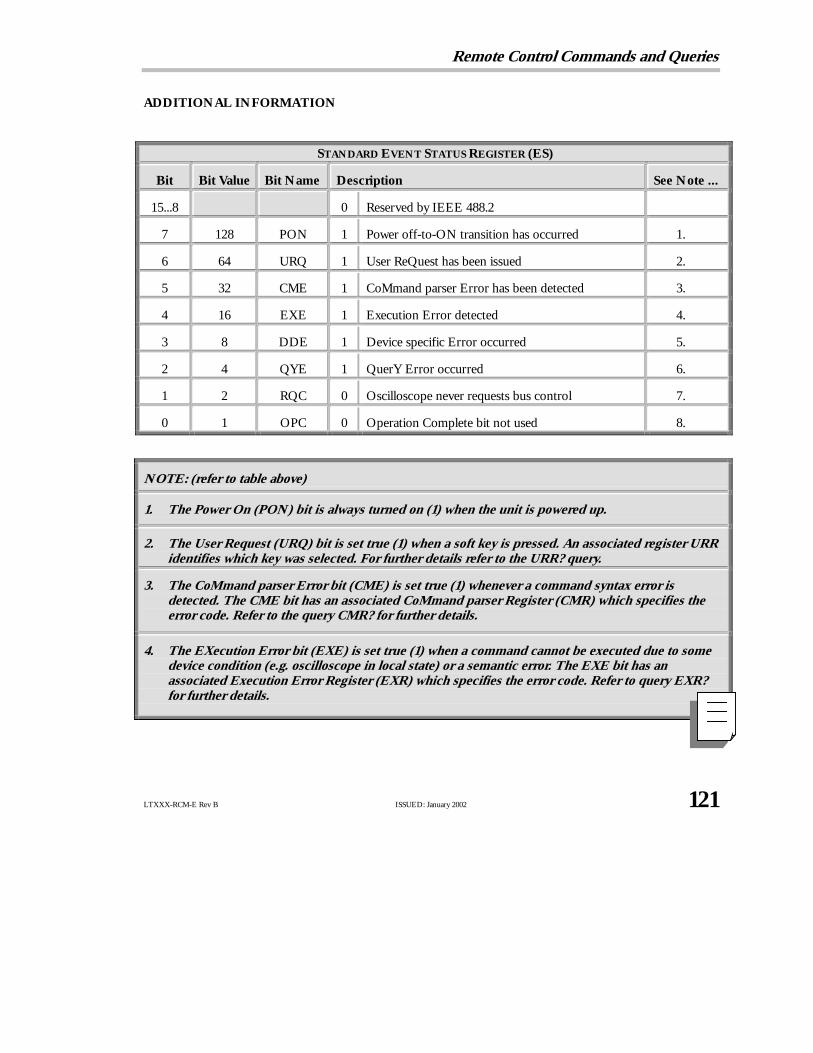
Remote Control Commands and Queries
LTXXX-RCM-E Rev B ISSUED: January 2002 121
ADDITIONAL INFORMATION
STANDARD EVENT STATUS REGISTER (ES)
Bit Bit Value Bit Name Description See Note ...
15...8 0 Reserved by IEEE 488.2
7 128 PON 1 Power off-to-ON transition has occurred 1.
6 64 URQ 1 User ReQuest has been issued 2.
5 32 CME 1 CoMmand parser Error has been detected 3.
4 16 EXE 1 Execution Error detected 4.
3 8 DDE 1 Device specific Error occurred 5.
2 4 QYE 1 QuerY Error occurred 6.
1 2 RQC 0 Oscilloscope never requests bus control 7.
0 1 OPC 0 Operation Complete bit not used 8.
NN OOTTEE :: (refer to table above)
1. The Power On (PON) bit is always turned on (1) when the unit is powered up.
2. The User Request (URQ) bit is set true (1) when a soft key is pressed. An associated register URRidentifies which key was selected. For further details refer to the URR? query.
3. The CoMmand parser Error bit (CME) is set true (1) whenever a command syntaxerror isdetected. The CME bit has an associated CoMmand parser Register (CMR) which specifies theerror code. Refer to the query CMR? for further details.
4. The EXecution Error bit (EXE) is set true (1) when a command cannot be executed due to somedevice condition (e.g. oscilloscope in local state) or a semantic error. The EXE bit has anassociated Execution Error Register (EXR) which specifies the error code. Refer to query EXR?for further details.

P A R T T W O : C O M M A N D S
122 ISSUED: January 2002 LTXXX-RCM-E Rev B
5. The Device specific Error (DDE) is set true (1) whenever a hardware failure has occurred atpower-up, or execution time, such as a channel overload condition, a trigger or a timebase circuitdefect. The origin of the failure can be localized via the DDR? or the self test * TST? query.
6. The Query Error bit (QYE) is set true (1) whenever (a) an attempt is made to read data from theOutput Queue when no output is either present or pending, (b) data in the Output Queue hasbeen lost, (c) both output and input buffers are full (deadlock state), (d) an attempt is made by thecontroller to read before having sent an <END>, (e) a command is received before the response tothe previous query was read (output buffer flushed).
7. The ReQuest Control bit (RQC) is always false (0), as the oscilloscope has no GPIB controllingcapability.
8. The OPeration Complete bit (OPC) is set true (1) whenever * OPC has been received, sincecommands and queries are strictly executed in sequential order. The oscilloscope starts processinga command only when the previous command has been entirely executed.

Remote Control Commands and Queries
LTXXX-RCM-E Rev B ISSUED: January 2002 123
STATUS EXR?Query
DESCRIPTION TheEXR? query reads and clears the contents of the EXecution errorRegister (EXR). The EXR register specifies the type of the last errordetected during execution. Refer to the table next page.
QUERY SYNTAX EXR?
RESPONSE FORMAT EXR <value>
<value> : = 21 to 64
EXAMPLE (GPIB) The following reads the contents of the EXR register:
CMD$=“EXR?”: CALL IBWRT(SCOPE%,CMD$):
CALL IBRD(SCOPE%,RSP$): PRINT RSP$
Response message (if no fault):
EXR 0
RELATED COMMANDS ALL_STATUS, *CLS

P A R T T W O : C O M M A N D S
124 ISSUED: January 2002 LTXXX-RCM-E Rev B
ADDITIONAL INFORMATION
EXECUTION ERROR STATUS REGISTER STRUCTURE (EXR)
Value Description
21 Permission error. The command cannot be executed in local mode.
22 Environment error. The oscilloscope is not configured to correctly process a command. Forinstance, the oscilloscope cannot be set to RIS at a slow timebase.
23 Option error. The command applies to an option which has not been installed.
24 Unresolved parsing error.
25 Parameter error. Too many parameters specified.
26 Non-implemented command.
30 Hex data error. A non-hexadecimal character has been detected in a hex data block.
31 Waveform error. The amount of data received does not correspond to descriptor indicators.
32 Waveform descriptor error. An invalid waveform descriptor has been detected.
33 Waveform text error. A corrupted waveform user text has been detected.
34 Waveform time error. Invalid RIS or TRIG time data has been detected.
35 Waveform data error. Invalid waveform data have been detected.
36 Panel setup error. An invalid panel setup data block has been detected.
50 No mass storage present when user attempted to access it. *
51 Mass storage not formatted when user attempted to access it. *
53 Mass storage was write protected when user attempted to create, or a file, to delete a file, or toformat the device. *
54 Bad mass storage detected during formatting. *
55 Mass storage root directory full. Cannot add directory. *
56 Mass storage full when user attempted to write to it. *
57 Mass storage file sequence numbers exhausted (999 reached). *
58 Mass storage file not found. *
59 Requested directory not found. *
61 Mass storage filename not DOS compatible, or illegal filename. *
62 Cannot write on mass storage because filename already exists. *
* Only with memory card or removable hard disk option.

Remote Control Commands and Queries
LTXXX-RCM-E Rev B ISSUED: January 2002 125
DISPLAY FAT_CURSOR, FATCCommand/Query
DESCRIPTION FAT_CURSOR controls the width of the cursors.
COMMAND SYNTAX FAT_CURSOR,FATC <state>
<state> : = ON, OFF
QUERY SYNTAX FAT_CURSOR?
RESPONSE FORMAT FAT_CURSOR <state>
EXAMPLE (GPIB) The following sets the cursor appearance to fat:
CMD$=“FAT_CURSOR ON”: CALL IBWRT(SCOPE%,CMD$)

P A R T T W O : C O M M A N D S
126 ISSUED: January 2002 LTXXX-RCM-E Rev B
MASS STORAGE FILENAME, FLNMCommand/Query
DESCRIPTION TheFILENAME command is used to change the default filename givento any traces, setups and hard copies when they are being stored to amass storage device.
COMMAND SYNTAX FiLeNaMe TYPE,<type>,FILE,‘<filename>’
<type> : = C1, C2, C3, C4, TA, TB, TC, TD, SETUP, HCOPY
<filename> : = For C1 to TD, an alphanumeric string of up to eightcharacters forming a legal DOS filename. Up to five characters forSETUP and HCOPY.
NN OOTTEE :: No extension can be specified, as the oscilloscopeautomatically does this.
QUERY SYNTAX FiLeNaMe? TYPE,<type><type> : = ALL, C1, C2, C3, C4, TA, TB, TC, TD, SETUP,HCOPY
RESPONSE FORMAT FiLeNaMeTYPE,<type>,FILE,”<filename>“[,TYPE,<type>,FILE,”<filename>“...]
AVAILABILITY <trace> : = C3, C4 available only on four-channel oscilloscopes.
EXAMPLE (GPIB) The following designates channel 1 waveform files as TESTPNT6.xxx”where xxx is a numeric extension assigned by the scope:
CMD$=“FLNM TYPE,C1, FILE, ‘TESTPNT6’”:
CALL IBWRT(SCOPE%,CMD$)
RELATED COMMANDS DIRECTORY, FORMAT_CARD, FORMAT_FLOPPY,FORMAT_HDD, DELETE_FILE

Remote Control Commands and Queries
LTXXX-RCM-E Rev B ISSUED: January 2002 127
FUNCTION FIND_CTR_RANGE, FCRCommand
DESCRIPTION TheFIND_CTR_RANGE command automatically sets the center andwidth of a histogram to best display the accumulated events.
COMMAND SYNTAX <function> : Find_Ctr_Range
<function> : = TA,TB,TC,TD
AVAILABILITYOnly available with an option installed that includes Histograms.
EXAMPLE (GPIB) Assuming that Trace A (TA) has been defined as a histogram of one ofthe custom parameters, the following example will determine the bestcenter and width and then rescale the histogram:
CMD$=“TA:FCR”: CALL IBWRT(SCOPE%,CMD$)
RELATED COMMANDS DEFINE, PACU

P A R T T W O : C O M M A N D S
128 ISSUED: January 2002 LTXXX-RCM-E Rev B
MASS STORAGE FORMAT_CARD, FCRDCommand/Query
DESCRIPTION TheFORMAT_CARD command formats the memory card according tothe PCMIA/JEIDA standard with a DOS partition.
TheFORMAT_CARD? query returns the status of the card.
COMMAND SYNTAX Format_CaRD
QUERY SYNTAX Format_CaRD?
RESPONSE FORMAT Format_CaRD <card_status>[,<read/write>,<free_space>,<card_size>,<battery_status>]
<card_status> : = NONE, BAD, BLANK, DIR_MISSING, OK<read/write> : = WP, RW<free_space> : = A decimal number giving the number of bytes stillavailable on the card<card_size> : = A decimal number giving the total number of bytes onthe card.<battery_status> : = BAT_OK, BAT_LOW, BAT_BAD
AVAILABILITY Available only with the Memory Card option installed.
EXAMPLE (GPIB) The following will first format a memory card and then verify its status:
CMD$=“FCRD”: CALL IBWRT(SCOPE%,CMD$)
CMD$=“FCRD?”: CALL IBWRT(SCOPE%,CMD$):
CALL IBRD(SCOPE%,RSP$): PRINT RSP$
Response message:
FCRD OK,RW,130048,131072,BAT_OK
RELATED COMMANDS DIRECTORY

Remote Control Commands and Queries
LTXXX-RCM-E Rev B ISSUED: January 2002 129
ADDITIONAL INFORMATION
NOTATION
BAD Bad card after formatting
BAT_BAD Bad battery or no battery
BAT_LOW Battery should be replaced
BAT_OK Battery is in order
BLANK Current directory empty
DIR_MISSING No subdirectory present. The directory “LECROY1_DIR” will beautomatically created with the next “store” command
NONE No card
OK Card is correctly formatted
RW Read/Write authorized
WP Write protected

P A R T T W O : C O M M A N D S
130 ISSUED: January 2002 LTXXX-RCM-E Rev B
MASS STORAGE FORMAT_FLOPPY, FFLPCommand/Query
DESCRIPTION TheFORMAT_FLOPPY command formats a floppy disk in the DoubleDensity or High Density format.
TheFORMAT_FLOPPY? query returns the status of the floppy disk.
COMMAND SYNTAX Format_FLoPpy [< type>]
<type> : = DD, HD
If no argument is supplied, HD is used by default.
QUERY SYNTAX Format_FLoPpy?
RESPONSE FORMAT Format_FloPpy <floppy_status>[,<read/write>,<free_space>,<floppy_size>]
<floppy_status> : = NONE, BAD, BLANK, DIR_MISSING, OK
<read/write> : = WP, RW
<free_space> : = A decimal number giving the number of bytes stillavailable on the floppy.
<floppy_size> : = A decimal number giving the total number of byteson the floppy.
EXAMPLE (GPIB) The following will first format a floppy in the Double Density (720 kB)format and then verify its status:
CMD$=“FFLP DD”:IBWRT(SCOPE%,CMD$)CMD$=“FFLP?”:CALL IBWRT(SCOPE%,CMD$):
CALL IBRD(SCOPE%,RSP$): PRINT RSP$
Response message:
FFLP OK,RW,728064,737280,
RELATED COMMANDS DIRECTORY

Remote Control Commands and Queries
LTXXX-RCM-E Rev B ISSUED: January 2002 131
ADDITIONAL INFORMATION
NOTATION
BAD Bad floppy after formatting
BLANK Current directory empty
DD Double Density 720 kB formatted
DIR_MISSING No subdirectory present. The directory “LECROY1_DIR” will beautomatically created with the next “store” command.
HD High Density 1.44 MB formatted
NONE No floppy
OK Floppy is correctly formatted
RW Read/Write authorized
WP Write protected

P A R T T W O : C O M M A N D S
132 ISSUED: January 2002 LTXXX-RCM-E Rev B
MASS STORAGE FORMAT_HDD, FHDDCommand/Query
DESCRIPTION TheFORMAT_HDD command formats the removable hard diskaccording to the PCMIA/JEIDA standard with a DOS partition.
TheFORMAT_HDD? query returns the status of the hard disk.
COMMAND SYNTAX Format_HDD <type>
<type> : = QUICK, FULL . If no argument is given, QUICK isused.
QUERY SYNTAX Format_HDD?
RESPONSE FORMAT Format_HDD <hdd_status>[,<read/write>,<free_space>,
<hdd_size>]
<hdd_status> : = NONE, BAD, BLANK, DIR_MISSING, OK<read/write> : = WP, RW<free_space> : = A decimal number giving the number of byte stillavailable on the hard disk<hdd_size> : = A decimal number giving the total number of byteson the hard disk.
AVAILABILITY Available only when the removable hard disk option is fitted.
EXAMPLE (GPIB) The following will first format a hard disk and then verify its status:
CMD$=“FHDD”: CALL IBWRT(SCOPE%,CMD$)CMD$=“FHDD?”: CALL IBWRT(SCOPE%,CMD$):CALL IBRD(SCOPE%,RSP$): PRINT RSP$
Response message:
FHDD OK,RW,3076096,105744896
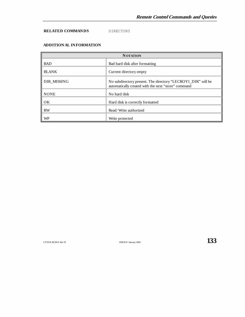
Remote Control Commands and Queries
LTXXX-RCM-E Rev B ISSUED: January 2002 133
RELATED COMMANDS DIRECTORY
ADDITIONAL INFORMATION
NOTATION
BAD Bad hard disk after formatting
BLANK Current directory empty
DIR_MISSING No subdirectory present. The directory “LECROY1_DIR” will beautomatically created with the next “store” command
NONE No hard disk
OK Hard disk is correctly formatted
RW Read/Write authorized
WP Write protected

P A R T T W O : C O M M A N D S
134 ISSUED: January 2002 LTXXX-RCM-E Rev B
DISPLAY FULL_SCREEN, FSCRCommand/Query
DESCRIPTION TheFULL_SCREEN command is used to control whether the currentlyselected grid style is displayed in normal presentation format or with afull-screen grid. In Full Screen format, the waveform display areas areenlarged to the maximum possible size.
The response to theFULL_SCREEN? query indicates whether or notthe display is operating in Full Screen presentation format.
COMMAND SYNTAX FullSCReen <state>
<state> : = ON, OFF
QUERY SYNTAX FullSCReen?
RESPONSE FORMAT FullSCReen <state>
EXAMPLE (GPIB) The following enables the Full Screen presentation format:
CMD$=“FSCR ON”: CALL IBWRT(SCOPE%,CMD$)

Remote Control Commands and Queries
LTXXX-RCM-E Rev B ISSUED: January 2002 135
FUNCTION FUNCTION_RESET, FRSTCommand
DESCRIPTION TheFUNCTION_RESET command resets a waveform processingfunction. The number of sweeps will be reset to zero and the processrestarted.
COMMAND SYNTAX <function> : Function_ReSeT
EXAMPLE (GPIB) <function> : = TA,TB,TC,TD
Assuming that Trace A (TA) has been defined as the summed averageof Channel 1, the following will restart the averaging process:
CMD$=“TA:FRST”: CALL IBWRT(SCOPE%,CMD$)
RELATED COMMANDS DEFINE, INR

P A R T T W O : C O M M A N D S
136 ISSUED: January 2002 LTXXX-RCM-E Rev B
ACQUISITION GLOBAL_BWL, GBWLCommand/Query
DESCRIPTION The GLOBAL_BWL command turns on or off the Global BandwidthLimit. When on, the selected bandwidth limit will apply to all channels;when off, a bandwidth limit can be set individually for each channel (seeBWL, page 69). The response to theGLOBAL_BWL? query indicateswhether the Global Bandwidth Limit is on or off.
COMMAND SYNTAX Global_BWL <mode>
<mode> : = OFF, ON
QUERY SYNTAX Global_BWL?
RESPONSE FORMAT Global_BWL <mode>
EXAMPLE The following deactivates the Global Bandwidth Limit, allowing aBandwidth Limit to be set individually for each channel (using the BWLcommand syntax for individual channels):
CMD$=“GBWL OFF”: CALL IBWRT(SCOPE%,CMD$)
RELATED COMMANDS BANDWIDTH_LIMIT

Remote Control Commands and Queries
LTXXX-RCM-E Rev B ISSUED: January 2002 137
DISPLAY GRIDCommand/Query
DESCRIPTION TheGRID command defines the style of the grid used in the display.
TheGRID? query returns the grid style currently in use.
COMMAND SYNTAX GRID <grid>
In standard display:
<grid> : = SINGLE, DUAL, QUAD, OCTAL
In XY display:
<grid> : = SINGLE, DUAL, XYONLY
QUERY SYNTAX GRID?
RESPONSE FORMAT GRID <grid>
EXAMPLE (GPIB) The following sets the screen display to dual grid mode:
CMD$=“GRID DUAL”: CALL IBWRT(SCOPE%,CMD$)

P A R T T W O : C O M M A N D S
138 ISSUED: January 2002 LTXXX-RCM-E Rev B
HARD COPY HARDCOPY_SETUP, HCSUCommand/Query
DESCRIPTION TheHARDCOPY_SETUP command configures the oscilloscope’shardcopy driver. It enables you to specify the device type andtransmission mode of the hardcopy unit connected to the oscilloscope.One or more individual settings can be changed by specifying theappropriate keyword(s), together with the newvalue(s). See followingpages for command notation and printer or plotter model availability.
COMMAND SYNTAX HardCopy_SetUp DEV, <device>,PORT,<port>,PFEED,
<page_feed>,PENS,<plot_pens>, PSIZE,<paper_size> CMDIV,
<cmdiv>,AUTO,<auto>,FORMAT,<format>, BCKG,<bckg>
<device> : = BMP, BMPCOMP,CANONCOL, EPSON, EPSONCOL,HPDJ, HPDJBW, HPPJ, HPTJ, HPLJ, HP7470A, HP7550A,TIFF, TIFFCOL TIFFCOMP
<port> : = GPIB, RS, CENT, FLPY, CARD, HDD, PRT
<page_feed> : = OFF, ON
<plot_pens> : = 1 to 8
<paper_size> : = A5, A4
<cmdiv> : = 1, 2, 5, 10, 20, 50, 100, 200
<auto> : = OFF, ON
<format> : = PORTRAIT, LANDSCAPE
<bckg> : = BLACK, WHITE
QUERY SYNTAX HardCopy_SetUp?
RESPONSE FORMAT HardCopy_SetUp DEV,<device>, PORT,<port>,PFEED,<page_feed>, PENS,<plot_pens>, PSIZE,<paper_size>,CMDIV,<cmdiv>,AUTO,<auto>,FORMAT,<format>, BCKG,<bckg>
AVAILABILITY<card> : CARD only with Memory Card option installed.

Remote Control Commands and Queries
LTXXX-RCM-E Rev B ISSUED: January 2002 139
<port> : HDD only with removable Hard Disk option installed.<port> : PRT only with internal graphics printer installed.<cmdiv> only with internal graphics printer installed.<auto> only with internal graphics printer installed.<device> See table below.
EXAMPLE (GPIB) The following example selects an EPSON printer connected via theRS232 port:
CMD$=“HCSU PORT,RS,DEV,EPSON”
CALL IBWRT(SCOPE%,CMD$)
RELATED COMMANDS HARDCOPY_TRANSMIT, SCREEN_DUMP
ADDITIONAL INFORMATION Hardcopy command parameters are grouped in pairs. The first in thepair names the variable to be modified, while the second gives the newvalue to be assigned. Pairs can be given in any order and restricted tothose variables to be changed.
The table below lists the printer and graphic formats you can use forproducing hardcopies remotely using <device>.
NOTATION PRINTER, PLOTTER OR PROTOCOL
BMP BMP
BMPCOMP BMP compressed
CANONCOL Canon 200/600/800 Series color printers
EPSON Epson b & w
EPSONCOL Epson color
HPLJ HP LaserJet
HPDJ HP Desk Jet color
HPDJBW HP Desk Jet b & w
HP7470A HP 7470A plotter
HP7550A HP 7550A plotter
HPGL Vector screen file
TIFF TIFF
TIFFCOL TIFF color
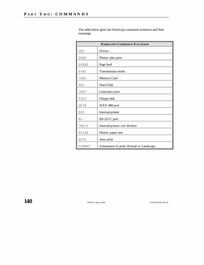
P A R T T W O : C O M M A N D S
140 ISSUED: January 2002 LTXXX-RCM-E Rev B
The table belowgives the Hardcopy command notations and theirmeanings.
HARDCOPY COMMAND NOTATION
DEV Device
PENS Plotter: plot pens
PFEED Page feed
PORT Transmission mode
CARD Memory Card
HDD Hard Disk
CENT Centronics port
FLPY Floppy disk
GPIB IEEE-488 port
PRT Internal printer
RS RS-232-C port
CMDIV Internal printer: cm/division
PSIZE Plotter: paper size
AUTO Auto print
FORMAT Orientation of print: Portrait or Landscape

Remote Control Commands and Queries
LTXXX-RCM-E Rev B ISSUED: January 2002 141
HARD COPY HARDCOPY_TRANSMIT, HCTRCommand
DESCRIPTION The HARDCOPY_TRANSMIT command sends a string of ASCIIcharacters without modification to the hardcopy unit. This allows youto control the hardcopy unit by sending device-specific controlcharacter sequences. It also allows placing of additional text on ascreen dump for documentation purposes.
COMMAND SYNTAX HardCopy_TRansmit ‘<string>’
<string> : = Any sequence of ASCII characters or escape sequences.
NN OOTTEE :: This command accepts the escape sequences asdescribed under the command COMM_RS232. Before sendingthe string to the hardcopy unit the escape sequence is convertedto the ASCII character code.
EXAMPLE (GPIB) The following sends documentation data to a printer:
CMD$=“HCTR ‘Data from Oct.15\r\n’” CALLIBWRT(SCOPE%,CMD$)
RELATED COMMANDS HARDCOPY_SETUP, SCREEN_DUMP

P A R T T W O : C O M M A N D S
142 ISSUED: January 2002 LTXXX-RCM-E Rev B
DISPLAY HOR_MAGNIFY, HMAGCommand/Query
DESCRIPTION TheHOR_MAGNIFY command horizontally expands the selectedexpansion trace by a specified factor. Magnification factors not withinthe range of permissible values will be rounded off to the closest legalvalue.
If multiple zoom is enabled, the magnification factor for all expansiontraces is set to the specified factor. If the specified factor is too largefor any of the expanded traces (depending on their current source), itis reduced to an acceptable value and only then applied to the traces.
The VAB bit (bit 2) in the STB register (see table on page 210) is setwhen a factor outside the legal range is specified.
TheHOR_MAGNIFY? query returns the current magnification factorfor the specified expansion function.
COMMAND SYNTAX <exp_trace> : Hor_MAGnify <factor>
<exp_trace> : = TA, TB, TC, TD<factor> : = 1 to 20000
QUERY SYNTAX <exp_source> : Hor_MAGnify?
RESPONSE FORMAT <exp_source> : Hor_MAGnify <factor>
EXAMPLE (GPIB) The following horizontally magnifies Trace A (TA) by a factor of 5:
CMD$=“TA:HMAG 5”: CALL IBWRT(SCOPE%,CMD$)
RELATED COMMANDS DUAL_ZOOM, MULTI_ZOOM
Remote Control Commands and Queries
LTXXX-RCM-E Rev B ISSUED: January 2002 143
DISPLAY HOR_POSITION, HPOSCommand/Query
DESCRIPTION TheHOR_POSITION command horizontally positions the geometriccenter of the intensified zone on the source trace. Allowed positionsrange from division 0 through 10. If the source trace was acquired insequence mode, horizontal shifting will only apply to a single segmentat a time.
If the multiple zoom is enabled, the difference between the specifiedand the current horizontal position of the specified trace is applied toall expanded traces. If this would cause the horizontal position of anyexpanded trace to go outside the left or right screen boundaries, thedifference of positions is adapted and then applied to the traces.
If the sources of expanded traces are sequence waveforms, and themultiple zoom is enabled, the difference between the specified and thecurrent segment of the specified trace is applied to all expandedtraces. If this would cause the segment of any expanded trace to gooutside the range of the number of source segments, the difference isadapted and then applied to the traces.
The VAB bit (bit 2) in the STB register (see table on page 210) is set ifa value outside the legal range is specified.
TheHOR_POSITION? query returns the position of the geometriccenter of the intensified zone on the source trace.
NN OOTTEE :: Segment number 0 has the special meaning “Show AllSegments Unexpanded”.
COMMAND SYNTAX <exp_trace> : Hor_POSition <hor_position>,<segment><exp_trace> : = TA, TB, TC, TD
<hor_position> : = 0 to 10 DIV<segment> : = 0 to max segments
NN OOTTEE :: The segment number is only relevant for waveformsacquired in sequence mode; it is ignored in single waveformacquisitions. When the segment number is set to 0, all segmentswill be shown.
The suffixDIV is optional.

P A R T T W O : C O M M A N D S
144 ISSUED: January 2002 LTXXX-RCM-E Rev B
QUERY SYNTAX <exp_trace> : Hor_POSition?
RESPONSE FORMAT <exp_trace> : Hor_POSition <hor_position>[,<segment>]
NN OOTTEE :: The segment number is only given for sequencewaveforms.
EXAMPLE (GPIB) The following positions the center of the intensified zone on the tracecurrently viewed by Trace A (TA) at division 3:
CMD$=“TA:HPOS 3”: CALL IBWRT(SCOPE%,CMD$)
RELATED COMMANDS DUAL_ZOOM, MULTI_ZOOM

Remote Control Commands and Queries
LTXXX-RCM-E Rev B ISSUED: January 2002 145
MISCELLANEOUS *IDN?Query
DESCRIPTION The*IDN? query is used for identification purposes. The responseconsists of four different fields providing information on themanufacturer, the scope model, the serial number and the firmwarerevision level.
QUERY SYNTAX *IDN?
RESPONSE FORMAT *IDN LECROY,<model>,<serial_number>,<firmware_level>
<model> : = A six- or seven-character model identifier<serial_number> : = A nine- or 10-digit decimal code<firmware_level> : = two digits giving the major release levelfollowed by a period, then one digit giving the minor release levelfollowed by a period and a single-digit update level (xx.y.z)
EXAMPLE (GPIB) This issues an identification request to the scope:
CMD$=“*IDN?”: CALL IBWRT(SCOPE%,CMD$):CALL IBRD(SCOPE%,RSP$): PRINT RSP$
Response message:
*IDN LECROY,9314CM,931401000,7.7.0

P A R T T W O : C O M M A N D S
146 ISSUED: January 2002 LTXXX-RCM-E Rev B
STATUS INECommand/Query
DESCRIPTION TheINE command sets the Internal state change Enable register(INE). This command allows one or more events in the INRregister to be reflected in the INB summary message bit (bit 0) ofthe STB register. For an overviewof the INR defined events, referto the table next page.
TheINE? query reads the contents of the INE register.
COMMAND SYNTAX INE <value>
<value> : = 0 to 65535
QUERY SYNTAX INE?
RESPONSE FORMAT INE <value>
EXAMPLE (GPIB) The following allows the INB bit to be set whenever a screen dumphas finished (bit 1, i.e. decimal 2), or a waveform has been acquired(bit 0, i.e. decimal 1), or both of these. Summing these two valuesyields the INE mask 2+1=3.
CMD$=“INE 3”: CALL IBWRT(SCOPE%,CMD$)
RELATED COMMANDS INR?

Remote Control Commands and Queries
LTXXX-RCM-E Rev B ISSUED: January 2002 147
STATUS INR?Query
DESCRIPTION TheINR? Query reads and clears the contents of the Internal statechange Register (INR). The INR register (table below) records thecompletion of various internal operations and state transitions.
INTERNAL STATE REGISTER STRUCTURE (INR)
Bit Bit Value Description
15 0 Reserved for future use.
14 16384 1 Probe was changed.
13 8192 1 Trigger is ready.
12 4096 1 Pass/Fail test detected desired outcome.
11 2048 1 Waveform processing has terminated in Trace D.
10 1024 1 Waveform processing has terminated in Trace C.
9 512 1 Waveform processing has terminated in Trace B.
8 256 1 Waveform processing has terminated in Trace A.
7 128 1 A memory card, floppy or hard disk exchange has been detected.
6 64 1 Memory card, floppy or hard disk has become full in AutoStore Fill mode.
5 32 0 Reserved for LeCroy use.
416
1 A segment of a sequence waveform has been acquired in acquisitionmemory but not yet read out into the main memory.
3 8 1 A time-out has occurred in a data block transfer.
2 4 1 A return to the local state is detected.
1 2 1 A screen dump has terminated.
01
1 A newsignal has been acquired in acquisition memory and read out into themain memory.

P A R T T W O : C O M M A N D S
148 ISSUED: January 2002 LTXXX-RCM-E Rev B
QUERY SYNTAX INR?
RESPONSE FORMAT INR <state>
<state> : = 0 to 65535
EXAMPLE (GPIB) The following reads the contents of the INR register:
CMD$=“INR?”: CALL IBWRT(SCOPE%,CMD$)
Response message:
INR 1026
i.e. waveform processing in Function C and a screen dump have bothterminated.
RELATED COMMANDS ALL_STATUS, *CLS, INE

Remote Control Commands and Queries
LTXXX-RCM-E Rev B ISSUED: January 2002 149
WAVEFORM TRANSFER INSPECT?, INSP?Query
DESCRIPTION TheINSPECT? query allows you to read parts of an acquiredwaveform in intelligible form. The command is based on theexplanation of the format of a waveform given by the template (usetheTEMPLATE? query to obtain an up-to-date copy).
Any logical block of a waveform can be inspected using this query bygiving its name enclosed in quotes as the first (string) parameter (seethe template itself).
The special logical block named WAVEDESC can also be inspected inmore detail. By giving the name of a variable in the block WAVEDESC,enclosed in quotes as the first (string) parameter, it is possible to inspectonly the actual value of that variable. See Chapter 4 for more onINSPECT?.
NOTATION
BYTE rawdata as integers (truncated to 8 most significant bits)
FLOAT normalized data (gain, offset applied) as floating pointnumbers (gives measured values in volts or units)
WORD rawdata as integers (truncated to 16 most significant bits)
QUERY SYNTAX <trace> : INSPect? ‘<string>’[,<data_type>]
<trace> : = TA, TB, TC, TD, M1, M2, M3, M4, C1, C2, C3,C4
<string> : =
<data_type> : = BYTE, WORD, FLOAT
NN OOTTEE :: The optional parameter <data_type> applies only forinspecting the data arrays. It selects the representation of thedata. The default <data_type> is FLOAT.

P A R T T W O : C O M M A N D S
150 ISSUED: January 2002 LTXXX-RCM-E Rev B
RESPONSE FORMAT <trace> : INSPect “<string>“
<string> : = A string giving name(s) and value(s) of a logical block or avariable.
AVAILABILITY <trace> : = C3, C4 only on four-channel oscilloscopes.
EXAMPLES (GPIB) The following reads the value of the timebase at which the lastwaveform in Channel 1 was acquired:
CMD$=“C1:INSP? ‘TIMEBASE’”
CALL IBWRT(SCOPE%,CMD$)
CALL IBRD(SCOPE%,RSP$)
PRINT RSP$
Response message:
C1:INSP “TIMEBASE: 500 US/DIV”
The following reads the entire contents of the waveform descriptorblock:
CMD$=“C1:INSP? ‘WAVEDESC’”
RELATED COMMANDS TEMPLATE, WAVEFORM_SETUP

Remote Control Commands and Queries
LTXXX-RCM-E Rev B ISSUED: January 2002 151
DISPLAY INTENSITY, INTSCommand/Query
DESCRIPTION TheINTENSITY command sets the intensity level of the grid, or thetrace or text.
The intensity level is expressed as a percentage (PCT). A level of 100PCT corresponds to the maximum intensity while a level of 0 PCTsets the intensity to its minimum value.
The response to theINTENSITY? query indicates the grid andtrace intensity levels.
COMMAND SYNTAX INTenSity GRID,<value>,TRACE,<value>
<value> : = 0 to 100 [PCT]
NN OOTTEE :: Parameters are grouped in pairs. The first of the pairnames the variable to be modified, while the second gives thenew value to be assigned. Pairs can be given in any order and berestricted to those variables to be changed.
The suffixPCT is optional.
QUERY SYNTAX INTenSity?
RESPONSE FORMAT INTenSity TRACE,<value>,GRID,<value>
EXAMPLE (GPIB) The following enables remote control of the intensity, and changesthe grid intensity level to 75 %:
CMD$=“INTS GRID,75”: CALL IBWRT(SCOPE%,CMD$)

P A R T T W O : C O M M A N D S
152 ISSUED: January 2002 LTXXX-RCM-E Rev B
ACQUISITION INTERLEAVED, ILVDCommand/Query
DESCRIPTION TheINTERLEAVED command enables or disables randominterleaved sampling (RIS) for timebase settings where both singleshot and RIS mode are available. See the specifications in theOperator’s Manual.
RIS is not available for sequence mode acquisitions.
The response to theINTERLEAVED? query indicates whether theoscilloscope is in RIS mode.
COMMAND SYNTAX InterLeaVeD <mode>
<mode> : = ON, OFF
QUERY SYNTAX InterLeaVeD?
RESPONSE FORMAT InterLeaVeD <mode>
EXAMPLE The following instructs the oscilloscope to use RIS mode:
CMD$=“ILVD ON”: CALL IBWRT(SCOPE%,CMD$)
RELATED COMMANDS TIME_DIV, TRIG_MODE, MEMORY_SIZE

Remote Control Commands and Queries
LTXXX-RCM-E Rev B ISSUED: January 2002 153
STATUS *IST?Query
DESCRIPTION The*IST? (Individual STatus) query reads the current state of theIEEE 488.1-defined “ist” local message. The “ist” individual statusmessage is the status bit sent during a parallel poll operation.
QUERY SYNTAX *IST?
RESPONSE FORMAT *IST <value>
<value> : = 0 or 1
EXAMPLE (GPIB) The following cause the contents of the IST bit to be read:
CMD$=“*IST?”: CALL IBWRT(SCOPE%,CMD$):
CALL IBRD(SCOPE%,RSP$): PRINT RSP$
Response message
*IST 0
RELATED COMMANDS *PRE

P A R T T W O : C O M M A N D S
154 ISSUED: January 2002 LTXXX-RCM-E Rev B
DISPLAY KEYCommand
DESCRIPTION TheKEY command allows control of a program from theWaverunner front panel. You can display one or two lines of 13characters each in menus corresponding to the lower six menubuttons (soft keys). The top menu is reserved for GO TO LOCAL.
You can also assign an executable file, such as AUTOEXEC.DSO, to amenu button. AUTOEXEC.DSO is a text file containing remotecommands. If the file is present, the scope will read the file from thefloppy or memory card and execute the remote commands containedin it.
String text that you assign to these menus disappears when youswitch to local, but reappears when you switch back to the remotestate. Text is cleared at power-up, whenever you reset theoscilloscope, or when you assign an empty string to a location. Forexample: KEY 2, ‘ ’.
Pressing any one of the menu buttons in remote mode causes theUser Request status Register (URR) and the URQ bit of the EventStatus Register to be set. This can generate an SRQ, provided thatthe service request mechanism has been enabled.
COMMAND SYNTAX KEY <button>,‘<string>’,‘<string>’
KEY <button>,’<string>’,’<string>’,’<file_name>’<button> : = 1 to 5<string> : = Up to two 13-character strings (any ASCII code)<file_name> : = autoexec.dso
EXAMPLE (GPIB) The menus illustrated this page were created by issuing the following:
CMD$=“KEY 2, ‘Pause’; KEY 3,‘Continue’,‘Measurement’;
KEY 4, ‘ ’, ‘GO’”: CALL IBWRT(SCOPE%,CMD$)
RELATED COMMANDS URR

Remote Control Commands and Queries
LTXXX-RCM-E Rev B ISSUED: January 2002 155
DISPLAY LOGOCommand/Query
DESCRIPTION The LOGO command controls the placement of the LeCroy logo atthe top left corner of the time grid or the XY grid.
COMMAND SYNTAX LOGO <state>
<state> : = ON, OFF
QUERY SYNTAX LOGO?
RESPONSE FORMAT LOGO <state>
EXAMPLE (GPIB) The following turns on the logo:
CMD$=“LOGO ON”: CALL IBWRT(SCOPE%,CMD$)
P A R T T W O : C O M M A N D S
156 ISSUED: January 2002 LTXXX-RCM-E Rev B
MASKCommand/Query
DESCRIPTION For PolyMask:
MASK COLOR allowyou to select two colors: one for the mask andone for displaying circles around sample points outside the mask.
MASK DISP_FILLED selects whether the mask is filled or not.During testing, the mask will always be filled, regardless of the stateof this selection.
MASK DRAWTO draws a line from the current position to a newposition. It is a command only.
MASK ERASE erases the current mask.
MASK FILL fills the enclosed polygram from starting position. It isa command only.
MASK MOVETO Moves the cursor to a newposition withoutdrawing a line. It is a command only.
SHOW_FAIL determines if errors inside or outside the mask shouldbe circled.
COMMAND SYNTAX <destination>:MASK COLOR <mask colors>,<error color>
See the table of color choices under COLOR command
<destination>:MASK DISP_FILLED <state>
<state> : = YES,NO
<destination>:MASK DRAWTO <x_value>,<y_value>
<x_value> : = 0 to 10 divisions (–4 to +4 divisions for XY Plot)
<y_value> : = –4 to +4 divisions
<destination>:MASK ERASE
<destination>:MASK FILL <x_value>,<y_value>
<x_value> : = 0 to 10 divisions
<y_value> : = –4 to +4 divisions

Remote Control Commands and Queries
LTXXX-RCM-E Rev B ISSUED: January 2002 157
<destination>:MASK MOVETO <x_value>,<y_value>
<x_value> : = 0 to 10 divisions
<y_value> : = –4 to +4 divisions
<destination>:SHOW_FAIL <state>,<count><state> : = OFF, INSIDE, OUTSIDE<count> : = 1 to 1000
<destination> : = C1, C2, C3, C4, TA, TB, TC, TD, TXY, PMXY
QUERY SYNTAX MASK? COLOR
MASK? DISP_FILLED
EXAMPLE (GPIB) TA:MASK COLOR,BLUE,RED
P A R T T W O : C O M M A N D S
158 ISSUED: January 2002 LTXXX-RCM-E Rev B
DISPLAY MEASURE_GATE, MGATCommand/Query
DESCRIPTION TheMEASURE_GATE command is used to control whether or notthe parameter measurement gate region (the region between theparameter cursors) is highlighted. Highlighting is performed bymaking the trace area outside the measurement gate region a neutralcolor.
The response to theMEASURE_GATE? query indicates whether ornot the parameter measurement gate region is highlighted.
COMMAND SYNTAX Measure_GATe <state>
<state> : = ON, OFF
QUERY SYNTAX Measure_GATe?
RESPONSE FORMAT Measure_GATe <state>
EXAMPLE (GPIB) The following highlights the measurement gate region:
CMD$=“MGAT ON”: CALL IBWRT(SCOPE%,CMD$)

Remote Control Commands and Queries
LTXXX-RCM-E Rev B ISSUED: January 2002 159
ACQUISITION MEMORY_SIZE, MSIZCommand/Query
DESCRIPTION On most models where this command/query is available,MEMORY_SIZE allows selection of the maximum memory lengthused for acquisition. See the specifications in the Operator’s Manual.
TTIIPP:: Reduce the number of data points for faster throughput.
TheMEMORY_SIZE? query returns the current maximum memorylength used to capture waveforms. When the optional suffix NUM isused with the query, the response will be returned in standard numericformat.
COMMAND SYNTAX Memory_SIZe <size>
<size> : = 500, 1e+3, …, 2e+6, 4e+6, 8e+6 , for example, instandard numeric format.
Or, alternatively:
NN OOTTEE :: The oscilloscope willadapt to the closest valid <size> ornumerical <value> according toavailable channel memory. = 500, 1000, 2500, 5000, 10K, 25K, 50K, 100K, 250K,
500K, 1M, 2.5M, 5M, 10M
However, values not absolutely identical to those listed immediatelyabove will be recognized by the scope as numerical data (see the tableunder this heading in Chapter 1). For example, the scope will recognize1.0M as 1 millisample. But it will recognize 1.0MA as 1 megasample.
QUERY SYNTAX Memory_SIZe? [NUM]
RESPONSE FORMAT Memory_SIZe <size>
EXAMPLE The following will set the oscilloscope to acquire at most 10 000 datasamples per single-shot or RIS acquisition:
CMD$=“MSIZ 10K”: CALL IBWRT(SCOPE%,CMD$)
or CMD$=“MSIZ 10e+3”: CALL IBWRT(SCOPE%,CMD$)
RELATED COMMANDS TDIV

P A R T T W O : C O M M A N D S
160 ISSUED: January 2002 LTXXX-RCM-E Rev B
DISPLAY MESSAGE, MSGCommand/Query
DESCRIPTION TheMESSAGE command displays a string of characters in theMessage Field above the grid. The string can be up to 49 characters inlength. The string is displayed as long as the oscilloscope is in remotemode and no internal status message is generated. Turning theoscilloscope back to local mode deletes the message. After the nexttransition from local to remote the message will be redisplayed. Themessage is cleared at power-up, when the oscilloscope is reset, or if anempty string is sent (MSG “ ”).
The MESSAGE? query allows you to read the last message sent.
COMMAND SYNTAX MeSsaGe ‘<string>’
<string> : = A string of a maximum of 49 characters
QUERY SYNTAX MeSsaGe?
RESPONSE FORMAT MeSsaGe “<string>“
EXAMPLE (GPIB) The following causes the messageConnect Probe 1 to appear inthe message field:
CMD$=“MSG ‘*Connect Probe 1*’”: CALLIBWRT(SCOPE%,CMD$)

Remote Control Commands and Queries
LTXXX-RCM-E Rev B ISSUED: January 2002 161
DISPLAY MULTI_ZOOM, MZOMCommand/Query
DESCRIPTION With MULTI_ZOOM ON, the horizontal magnification andpositioning controls apply to all expanded traces simultaneously.This command is useful if the contents of all expanded traces are tobe examined at the same time.
TheMULTI_ZOOM? query indicates whether multiple zoom isenabled or not.
NN OOTTEE :: This command has the same effect as DUAL_ZOOM.
COMMAND SYNTAX Multi_ZOoM <mode>
<mode> : = ON, OFF
QUERY SYNTAX Multi_ZOoM?
RESPONSE FORMAT Multi_ZOoM <mode>
EXAMPLE (GPIB) The following example turns the multiple zoom on:
CMD$=“MZOM ON”: CALL IBWRT(SCOPE%,CMD$)
RELATED COMMANDS HOR_MAGNIFY, HOR_POSITION, DUAL_ZOOM

P A R T T W O : C O M M A N D S
162 ISSUED: January 2002 LTXXX-RCM-E Rev B
ACQUISITION OFFSET, OFSTCommand/Query
DESCRIPTION TheOFFSET command allows adjustment of the vertical offset of thespecified input channel.
The maximum ranges depend on the fixed sensitivity setting. See theOperator’s Manual.
If an out-of-range value is entered, the oscilloscope is set to theclosest possible value and the VAB bit (bit 2) in the STB register is set.
NN OOTTEE :: The probe attenuation factor is not taken into accountfor adjusting the offset.
The suffixV is optional.
TheOFFSET? query returns the DC offset value of the specifiedchannel.
COMMAND SYNTAX <channel> : OFfSeT <offset>
<channel> : = C1, C2, C3, C4
<offset> : = See the Operator’s Manual for specifications.
QUERY SYNTAX <channel> : OFfSeT?
RESPONSE FORMAT <channel> : OFfSeT <offset>
AVAILABILITY <channel> : C3, C4 only on four-channel oscilloscopes.
EXAMPLE (GPIB) The following sets the offset of Channel 2 to −3 V:
CMD$=“C2:OFST −3V”: CALL IBWRT(SCOPE%,CMD$)

Remote Control Commands and Queries
LTXXX-RCM-E Rev B ISSUED: January 2002 163
STATUS *OPCCommand/Query
DESCRIPTION The*OPC (OPeration Complete) command sets to true the OPCbit (bit 0) in the standard Event Status Register (ESR). Thiscommand has no other effect on the operation of the oscilloscopebecause the oscilloscope starts parsing a command or query onlyafter it has completely processed the previous command or query.
The*OPC? query always responds with the ASCII character “1”because the oscilloscope only responds to the query when theprevious command has been entirely executed.
COMMAND SYNTAX *OPC
QUERY SYNTAX *OPC?
RESPONSE FORMAT *OPC 1
RELATED COMMANDS *WAI

P A R T T W O : C O M M A N D S
164 ISSUED: January 2002 LTXXX-RCM-E Rev B
MISCELLANEOUS *OPT?Query
DESCRIPTION The*OPT? query identifies oscilloscope options: installed firmware orhardware that is additional to the standard Waverunner configuration.The response consists of a series of response fields listing all theinstalled options.
QUERY SYNTAX *OPT?
RESPONSE FORMAT *OPT <option_1>,<option_2>,..,<option_N>
<option_n> : = A three- or four-character ASCII string
NN OOTTEE :: If no option is present, the character 0 will be returned.
EXAMPLE (GPIB) The following queries the installed options:
CMD$=“*OPT?”: CALL IBWRT(SCOPE%,CMD$):
CALL IBRD(SCOPE%,RSP$): PRINT RSP$
If, for example, the waveform processing options EMM, GP02, JTA,MC04 and WAVA and are installed, the response will be returned as:
* EMM, GP02, JTA, MC04, WAVA
Response message if no options are installed:
*OPT 0

Remote Control Commands and Queries
LTXXX-RCM-E Rev B ISSUED: January 2002 165
ADDITIONAL INFORMATION
NOTATION
GP02 Internal Printer/Centronics Option
HD02 Hard Disk Option
JTA Jitter and Timing Analysis Option
MC02 PC Card Slot
EMM Extended Math and Measurement Option
WAVA WaveAnalyzer Option (includes histograms)

P A R T T W O : C O M M A N D S
166 ISSUED: January 2002 LTXXX-RCM-E Rev B
SAVE/RECALL SETUP PANEL_SETUP, PNSUCommand/Query
DESCRIPTION ThePANEL_SETUP command complements the*SAV or *RSTcommands. PANEL_SETUP allows you to archive panel setups inencoded form on external storage media.
Only setup data read by thePNSU? query can be recalled into theoscilloscope. A panel setup error (see table on page 124) will begenerated if the setup data block contains invalid data.
NN OOTTEE :: The communication parameters (those modified bycommands CFMT, CHDR, CHLP, CORD and WFSU) and theenable registers associated with the status reporting system(SRE, PRE, ESE, INE) are not saved by this command.
COMMAND SYNTAX PaNel_SetUp <setup>
<setup> : = A setup data block previously read by PNSU?
QUERY SYNTAX PaNel_SetUp?
RESPONSE SYNTAX PaNel_SetUp <setup>
EXAMPLE (GPIB) The following saves the oscilloscope’s current panel setup in the filePANEL.SET:
FILE$ = “PANEL.SET”: CMD$=“PNSU?”:
CALL IBWRT(SCOPE%,CMD$): CALL IBRDF(SCOPE%,FILE$)
Whereas the following recalls the front panel setup, stored previouslyin the file PANEL.SET, into the oscilloscope:
CALL IBWRTF(SCOPE%,FILE$)
RELATED COMMANDS *RCL, *SAV

Remote Control Commands and Queries
LTXXX-RCM-E Rev B ISSUED: January 2002 167
CURSOR PARAMETER_CLR, PACLCommand
DESCRIPTION ThePARAMETER_CLR command clears all the current parametersfrom the five-line list used in the Custom and Pass/Fail modes.
NN OOTTEE :: This command has the same effect as the commandPASS_FAIL_CONDITION, given without any arguments.
COMMAND SYNTAX PArameter_CLear
RELATED COMMANDS PARAMETER_DELETE, PARAMETER_VALUE,PASS_FAIL_CONDITION

P A R T T W O : C O M M A N D S
168 ISSUED: January 2002 LTXXX-RCM-E Rev B
CURSOR PARAMETER_CUSTOM, PACUCommand/Query
DESCRIPTION ThePARAMETER_CUSTOM command controls the parameters thathave customizable qualifiers and can also be used to assign anyparameter for histograms.
TIP: Use PAVA? to read the measured value of a parametersetup withPACU.
COMMAND SYNTAX PArameter_Custom<line>,<parameter>,<qualifier> [,<qualifier>,...]
< line> : = 1 to 5<parameter> : = a parameter from the table belowor any parameterlisted in the PAVA? command<qualifier> : = Measurement qualifier(s) specific to each <param>.See below.
<param> Definition <qualifier> list
CUSTOMIZABLE PARAMETERS ON ALL MODELS
DDLY delta delay <source1>,<source2>
PHASE phase difference <source1>,<edge1>,<level1>,<source2>,<edge2>,<level2> ,<hysteresis>,<angular unit>
CUSTOMIZABLE PARAMETERS WITH EXTENDED MATH OPTION
DTLEV delta time at level <source1>,<slope1>,<level1>,<source2>,<slope2>,<level2>,<hysteresis>
FLEV fall at level <source>,<high>,<low>
RLEV rise at level <source>,<low>,<high>
TLEV time at level <source>,<slope>,<level>,<hysteresis>
CUSTOMIZABLE PARAMETERS WITH WAVEANALYZER OPTION
CALCx calculated parameter results <source1>,<optional setup of source1>,<operator>,<source2>
FWXX full width at xx % of max <source>,<threshold>
PCTL percentile <source>,<threshold>
XAPK x position at peak <source>,<rank>

Remote Control Commands and Queries
LTXXX-RCM-E Rev B ISSUED: January 2002 169
Where:
<sourceN> : = C1, C2, C3, C4, TA, TB, TC, TD
<slopeN> : = POS, NEG, FIRST
<edgeN> : = POS, NEG
<clock edge> : = POS, NEG, ALL
< levelN>, <low>, <high> : = 1 to 99 if level is specified in percent(PCT), or
<levelN>, <low>, <high> : = Level in <sourceN> in the units of thewaveform.
<delay> : = −100 PCT to 100 PCT
<freq> : = 10 to 1e9 Hz (NarrowBand center frequency)
<hysteresis> : = 0.01 to 8 divisions
<length> : = 1e−9 to 0.001 seconds
<operator> : = ADD, SUB, MUL, DIV *
<rank> : = 1 to 100
<threshold> : = 0 to 100 percent
<angular unit> = PCT, DEG, RAD
QUERY SYNTAX PArameter_CUstom? <line>
RESPONSE FORMAT PArameter_Custom <line>,<parameter>,<qualifier> [,<qualifier>,...]
AVAILABILITY <sourceN> : = C3, C4 only on four-channel oscilloscopes.
EXAMPLE 1 DTLEV
Command Example: PACU 2,DTLEV,C1,POS,345E−3,C2,NEG,−789E−3
Query/Response Examples: PACU? 2 returns:
PACU 2,DTLEV,C1,POS,345E−3,C2,NEG,−789E−3PAVA? CUST2 returns:C2:PAVA CUST2,789 NS
* For Parameter Math option

P A R T T W O : C O M M A N D S
170 ISSUED: January 2002 LTXXX-RCM-E Rev B
EXAMPLE 2 DDLY
Command Example: PACU 2,DDLY,C1,C2
Query/Response Examples: PACU? 2 returns:PACU 2,DDLY,C1,C2
PAVA? CUST2 returns:C2:PAVA CUST2,123 NS
EXAMPLE 3 RLEV
Command Example: PACU 3,RLEV,C1,2PCT,67PCT
Query/Response Examples: PACU? 3 returns:PACU 3,RLEV,C1,2PCT,67PCT
PAVA? CUST3 returns:C1:PAVA CUST3,23 MS
EXAMPLE 4 FLEV
Command Example: PACU 3,FLEV,C1,345E−3,122E−3
Query/Response Examples: PACU? 3 returns:
PACU 3,FLEV,C1,345E−3,122E−3PAVA? CUST3 returns:C1:PAVA CUST3,23 MS
EXAMPLE 5 (Parameter Math) CALCx
Command Example: PACU 5,CALC1,AMPL,C3,DIV,AMPL,C2
Query/Response Examples: PACU? 5 returns:
PACU 5,CALC1,AMPL,C3,DIV,AMPL,C2
PAVA? CUST5 returns:
C2:PAVA CUST1,4.884,OK
RELATED COMMANDS PARAMETER_DELETE, PARAMETER_VALUE,PASS_FAIL_CONDITION

Remote Control Commands and Queries
LTXXX-RCM-E Rev B ISSUED: January 2002 171
CURSOR PARAMETER_DELETE, PADLCommand
DESCRIPTION ThePARAMETER_DELETE command deletes a parameter at aspecified line from the list of parameters used in the Custom andPass/Fail modes.
NOTATION
1 line 1 of Custom or Pass/Fail display
2 line 2 of Custom or Pass/Fail display
3 line 3 of Custom or Pass/Fail display
4 line 4 of Custom or Pass/Fail display
5 line 5 of Custom or Pass/Fail display
COMMAND SYNTAX PArameter_DeLete <line>
<line> : = 1, 2, 3, 4, 5
NN OOTTEE :: This command has the same effect as the commandPASS_FAIL_CONDITION <line>, given without any furtherarguments.
EXAMPLE (GPIB) The following deletes the third test condition in the list:
CMD$=“PADL 3”: CALL IBWRT(SCOPE%,CMD$)
RELATED COMMANDS PARAMETER_CLR, PARAMETER_VALUE,PASS_FAIL_CONDITION

P A R T T W O : C O M M A N D S
172 ISSUED: January 2002 LTXXX-RCM-E Rev B
CURSOR PARAMETER_STATISTICS?, PAST?Query
DESCRIPTION ThePARAMETER_STATISTICS? query returns the currentvalues of statistics for the specified pulse parameter mode and theresult type, for all five lines of the pulse parameters display.
NOTATION
AVG average
CUST custom parameters
HIGH highest value
HPAR horizontal standard parameters
LOW lowest value
PARAM parameter definition for each line
SIGMA sigma (standard deviation)
SWEEPS number of sweeps accumulated for each line
VPAR vertical standard parameters
QUERY SYNTAX PArameter_STatistics? <mode>, <result>
<mode> : = CUST, HPAR, VPAR
<result> : = AVG, LOW, HIGH, SIGMA, SWEEPS, PARAM
NN OOTTEE :: If keyword PARAM is specified, the query returns thelist of the five pairs <parameter_name>,<source>.
EXAMPLE (GPIB) The following query reads the average values of the fivestandard vertical parameters:
CMD$=“PAST? VPAR, AVG”: CALLIBWRT(SCOPE%,CMD$):
CALL IBRD(SCOPE%,RD$): PRINT RD%
RESPONSE FORMAT PAST VPAR, AVG, 13V, 26V, 47V, 1V, 0V
RELATED COMMANDS PARAMETER_VALUE
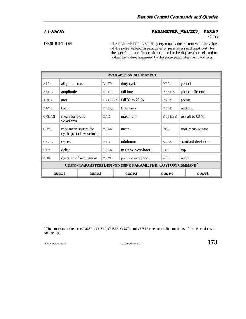
Remote Control Commands and Queries
LTXXX-RCM-E Rev B ISSUED: January 2002 173
CURSOR PARAMETER_VALUE?, PAVA?Query
DESCRIPTION ThePARAMETER_VALUE query returns the current value or valuesof the pulse waveform parameter or parameters and mask tests forthe specified trace. Traces do not need to be displayed or selected toobtain the values measured by the pulse parameters or mask tests.
AVAILABLE ON ALL MODELS
ALL all parameters DUTY duty cycle PER period
AMPL amplitude FALL falltime PHASE phase difference
AREA area FALL82 fall 80 to 20 % PNTS points
BASE base FREQ frequency RISE risetime
CMEAN mean for cyclicwaveform
MAX maximum RISE28 rise 20 to 80 %
CRMS root mean square forcyclic part of waveform
MEAN mean RMS root mean square
CYCL cycles MIN minimum SDEV standard deviation
DLY delay OVSN negative overshoot TOP top
DUR duration of acquisition OVSP positive overshoot WID width
CUSTOM PARAMETERS DEFINED USING PARAMETER_CUSTOM COMMAND*
CUST1 CUST2 CUST3 CUST4 CUST5
* The numbers in the terms CUST1, CUST2, CUST3, CUST4 and CUST5 refer to the line numbers of the selected customparameters.

P A R T T W O : C O M M A N D S
174 ISSUED: January 2002 LTXXX-RCM-E Rev B
AVAILABLE WITH EXTENDED MATH OR WAVEANALYZER OPTION
AVG average of distribution HRMS histogram rms value PKS number of peaks
CMEDI median for cyclicwaveform
HTOP histogram top value RANGE range of distribution
CSDEV standard deviation forcyclic part of waveform
LAST last point SIGMA sigma of distribution
FRST first point MAXP maximum population TOTP total population
HIGH high of histogram MEDI median value
HMEDI median of a histogram MODE mode of distribution
PARAMETER COMPUTATION STATES
AV averaged over several (up to 100) periods OF signal partially in overflow
GT greater than given value OK deemed to be determined without problem
IV invalid value (insufficient data provided) OU signal partially in overflowand underflow
LT less than given value PT windowhas been period truncated
NP no pulse waveform UF signal partially in underflow
MASK TEST NAMES
ALL_IN all points of waveform insidemask (TRUE = 1, FALSE = 0)
SOME_IN some points of waveform inside mask(TRUE = 1, FALSE = 0)
ALL_OUT all points of waveform outsidemask (TRUE = 1, FALSE = 0)
SOME_OUT some points of waveform outside mask(TRUE = 1, FALSE = 0)
QUERY SYNTAX <trace> : PArameter_VAlue? [<parameter>,...,<parameter>]
<trace> : = TA, TB, TC, TD, C1, C2, C3, C4
<parameter> : = See table of parameters.
Alternative forms of query for mask tests:

Remote Control Commands and Queries
LTXXX-RCM-E Rev B ISSUED: January 2002 175
<trace> : PArameter_VAlue? <mask_test>, <mask>
<mask_test> : = ALL_IN, SOME_IN, ALL_OUT, SOME_OUT
<mask> : = TA, TB, TC, TD
RESPONSE FORMAT <trace> : PArameter_VAlue <parameter>,<value>,
<state> [,...,<parameter>,<value>,<state>]
<value> : = A decimal numeric value
<state> : = OK, AV, PT, IV, NP, GT, LT, OF, UF, OU
NN OOTTEE :: If <parameter> is not specified, or is equal to ALL, allstandard voltage and time parameters are returned followed bytheir values and states.
AVAILABILITY <trace> : C3, C4 only available on four-channel oscilloscopes.
EXAMPLE (GPIB) The following query reads the risetime of Trace B (TB):
CMD$=“TB:PAVA? RISE”: CALL IBWRT(SCOPE%,CMD$):
CALL IBRD (SCOPE%,RD$): PRINT RD$
Response message:
TB:PAVA RISE,3.6E−9S,OK
RELATED COMMANDS CURSOR_MEASURE, CURSOR_SET, PARAMETER_CUSTOM,PARAMETER_STATISTICS

P A R T T W O : C O M M A N D S
176 ISSUED: January 2002 LTXXX-RCM-E Rev B
CURSOR PASS_FAIL_CONDITION, PFCOCommand/Query
DESCRIPTION ThePASS_FAIL_CONDITION command adds a Pass/Fail testcondition or a custom parameter at the specified line on the Pass/Failor Custom Parameter display.
ThePASS_FAIL_CONDITION? query indicates the currentPass/Fail test setup or the current selection of custom parameters atthe specified line.
NN OOTTEE :: Up to five test conditions (or custom parameters) can bespecified at five different display lines on the screen. Thecommand PASS_FAIL_CONDITION deals with one lineat a time.
N O T AT I O N
GT greater than LT lower than
COMMAND SYNTAX Pass_Fail_Condition[< line>,<trace>,<parameter>[,<rel_op> [,<ref_value>]]]
< line> : = 1,2,3,4,5
<trace> : = TA, TB, TC, TD, C1, C2, C3, C4
<parameter> : = See tables of parameters on pages 168 and 173.
<rel_op> : = GT, LT
<ref_value> : = −1e15 to +1e15
NN OOTTEE :: The PFCO command with no arguments (i.e. “PFCO”)deletes all conditions. The PFCO command with a singleargument (i.e. “PFCO <line>” ) deletes the condition at<line>.
Alternative form of command for mask tests:Pass_Fail_COndition [< line>,<trace>,<mask_test>,<mask>]
<mask_test> : = ALL_IN, SOME_IN, ALL_OUT, SOME_OUT
Remote Control Commands and Queries
LTXXX-RCM-E Rev B ISSUED: January 2002 177
<mask> : = TA, TB, TC, TDQUERY SYNTAX PFCO? <line>
RESPONSE FORMAT PFCO <line>,<trace>,<parameter>,<rel_op>,<ref_value>
Alternative form of response for mask tests:
PFCO <line>,<trace>,<mask_test>,<mask>
AVAILABILITY <trace> : = C3, C4 only on four-channel oscilloscopes.
EXAMPLE (GPIB) The following sets the first test condition in the list to be “frequency onChannel 1 lower than 10 kHz”:
CMD$=“PFCO 1,C1,FREQ,LT,10000”:
CALL IBWRT(SCOPE%,CMD$)
RELATED COMMANDS CURSOR_MEASURE, CURSOR_SET, PASS_FAIL_COUNTER,PASS_FAIL_DO, PASS_FAIL_MASK, PARAMETER_VALUE

P A R T T W O : C O M M A N D S
178 ISSUED: January 2002 LTXXX-RCM-E Rev B
CURSOR PASS_FAIL_COUNTER, PFCTCommand/Query
DESCRIPTION ThePASS_FAIL_COUNTER command resets the Passed/Failedacquisitions counters. The PASS_FAIL_COUNTER? queryreturns the current counts.
COMMAND SYNTAX Pass_Fail_CounTer
QUERY SYNTAX Pass_Fail_CounTer?
RESPONSE FORMAT Pass_Fail_CounTer <pass/fail>,<value>,OF,<value>
<value> : = 0 to 999999
<pass/fail> : = PASS, FAIL
EXAMPLE (GPIB) The following query reads the counters:
CMD$=“PFCT?”: CALL IBWRT(SCOPE%,CMD$)
Response message:
PFCT PASS, 8, OF, 9
RELATED COMMANDS CURSOR_MEASURE, CURSOR_SET, PASS_FAIL_DO,PASS_FAIL_MASK, PARAMETER_VALUE
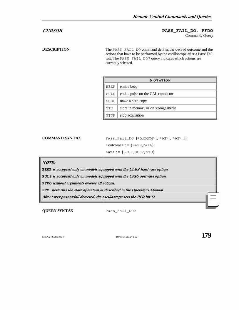
Remote Control Commands and Queries
LTXXX-RCM-E Rev B ISSUED: January 2002 179
CURSOR PASS_FAIL_DO, PFDOCommand/Query
DESCRIPTION ThePASS_FAIL_DO command defines the desired outcome and theactions that have to be performed by the oscilloscope after a Pass/Failtest. ThePASS_FAIL_DO? query indicates which actions arecurrently selected.
N O T AT I O N
BEEP emit a beep
PULS emit a pulse on the CAL connector
SCDP make a hard copy
STO store in memory or on storage media
STOP stop acquisition
COMMAND SYNTAX Pass_Fail_DO [<outcome>[,<act>[,<act>...]]]
<outcome> : = PASS,FAIL
<act> : = STOP, SCDP, STO
NN OOTTEE ::
BEEP is accepted only on models equipped with the CLBZ hardware option.
PULS is accepted only on models equipped with the CKIO software option.
PFDO without arguments deletes all actions.
STO performs the store operation as described in the Operator’s Manual.
After every pass or fail detected, the oscilloscope sets the INR bit 12.
QUERY SYNTAX Pass_Fail_DO?

P A R T T W O : C O M M A N D S
180 ISSUED: January 2002 LTXXX-RCM-E Rev B
RESPONSE FORMAT Pass_Fail_DO [<pass_fail> [,<act>[,<act>...]]]
EXAMPLE (GPIB) This following forces the oscilloscope to stop acquiring when the testpasses:
CMD$=“PFDO PASS,STOP”: CALL IBWRT(SCOPE%,CMD$)
RELATED COMMANDS BUZZER, CURSOR_MEASURE, CURSOR_SET, INR,PARAMETER_VALUE, PASS_FAIL_COUNTER,PASS_FAIL_MASK

Remote Control Commands and Queries
LTXXX-RCM-E Rev B ISSUED: January 2002 181
CURSOR PASS_FAIL_MASK, PFMSCommand
DESCRIPTION ThePASS_FAIL_MASK command generates a tolerance mask arounda chosen trace and stores the mask in the selected memory.
COMMAND SYNTAX Pass_Fail_MaSk [< trace>[,<htol>[,<vtol>[,<mask>]]]]
<trace> : = TA, TB, TC, TD, M1, M2, M3, M4, C1, C2, C3,C4
<htol> : = 0.0 to 5.0
<vtol> : = 0.0 to 4.0
<mask> : = M1, M2, M3, M4
NN OOTTEE :: if any arguments are missing, the previous settings willbe used.
The alternative form of command:
Pass_Fail_MaSk INVT [,<mask>]
inverts the mask in the selected mask memory. If <mask> is missing,M4 is implied.
AVAILABILITY <trace> : = C3, C4 only on four-channel oscilloscopes.
EXAMPLE (GPIB) The following generates a tolerance mask around the Channel 1 traceand stores it in M2:
CMD$=“PASS_FAIL_MASK C1,0.2,0.3,M2”:
CALL IBWRT(SCOPE%,CMD$)
RELATED COMMANDS PASS_FAIL_DO, PARAMETER_VALUE

P A R T T W O : C O M M A N D S
182 ISSUED: January 2002 LTXXX-RCM-E Rev B
CURSOR PASS_FAIL_STATUS?, PFST?Query
DESCRIPTION ThePASS_FAIL_STATUS query returns the status of the Pass/Failtest for a given line number.
QUERY SYNTAX Pass_Fail_STatus? <line>
<line> : = 1, 2, 3, 4, 5
RESPONSE FORMAT Pass_Fail_STatus <line>,<state>
<state> : = TRUE, FALSE
EXAMPLE (GPIB) The following queries the state of the Pass/Fail test conditionspecified for line 3.
CMD$=“PFST? 3”: CALL IBWRT(SCOPE%,CMD$)
RELATED COMMANDS PASS_FAIL_DO, PASS_FAIL_CONDITION,PARAMETER_VALUE

Remote Control Commands and Queries
LTXXX-RCM-E Rev B ISSUED: January 2002 183
CURSOR PER_CURSOR_SET, PECSCommand/Query
DESCRIPTION ThePER_CURSOR_SET command allows you to position any one ofthe six independent cursors at a given screen location. The position ofthe cursor can be modified or queried even if the cursor is not currentlydisplayed on the screen.
ThePER_CURSOR_SET? query indicates the current position of thecursor or cursors.
The vertical cursor positions are the same as those controlled by theCURSOR_SET command.
N O T AT I O N
HABS horizontal absolute VABS vertical absolute
HDIF horizontal difference VDIF vertical difference
HREF horizontal reference VREF vertical reference
COMMAND SYNTAX <trace> : PEr_Cursor_Set <cursor>,<position>[,<cursor>,<position>,...,<cursor>,<position>
trace> : = TA, TB, TC, TD, C1, C2, C3, C4
<cursor> : = HABS, HDIF, HREF, VABS, VDIF, VREF
<position> : = 0 to 10 DIV (horizontal), −29.5 to 29.5 DIV (vertical)
NN OOTTEE :: Parameters are grouped in pairs. The first of the pair names the variable to be modified, whilethe second gives the new value to be assigned. Pairs can be in any order and limited to those variables tobe changed.
The suffixDIV is optional.
If <cursor> is not specified, ALL will be assumed. If the position of a cursor cannot be determined ina particularsituation, its position will be indicated as UNDEF.
QUERY SYNTAX <trace> : PEr_Cursor_Set? <cursor>[,<cursor,...,<cursor> ]
<cursor> : = HABS, HDIF, HREF, VABS, VDIF, VREF, ALL

P A R T T W O : C O M M A N D S
184 ISSUED: January 2002 LTXXX-RCM-E Rev B
RESPONSE FORMAT PEr_Cursor_Set <cursor>,<position> [,<cursor> ,<position>,...,<cursor>,<position>
AVAILABILITY <trace> : = C3, C4 only available on four-channel oscilloscopes.
EXAMPLE (GPIB) The following positions the HREF and HDIF cursors at +2.6 DIV and+7.4 DIV respectively, using Channel 2 as a reference:
CMD$=“C2:PECS HREF,2.6 DIV,HDIF,7.4DIV”
RELATED COMMANDS CURSOR_MEASURE, CURSOR_SET, PERSIST,PER_CURSOR_VALUE

Remote Control Commands and Queries
LTXXX-RCM-E Rev B ISSUED: January 2002 185
CURSOR PER_CURSOR_VALUE?, PECV?Query
DESCRIPTION ThePER_CURSOR_VALUE? query returns the values measured bythe cursors specified belowwhile in Persistence mode.
N O T AT I O N
HABS horizontal absolute VABS vertical absolute
HREL horizontal relative VREL vertical relative
QUERY SYNTAX < trace> : PEr_Cursor_Value? <cursor>[,<cursor>,...,<cursor>]
<trace> : = TA, TB, TC, TD, C1, C2, C3, C4<cursor> : = HABS, HREL, VABS, VREL, ALL
Note: If <cursor> is not specified, AL L will beassumed.
RESPONSE FORMAT <trace> : PEr_Cursor_Value <cursor>,<value>[,<cursor>,<value>,...,<cursor>,<value>]
AVAILABILITY <trace> : = C3, C4 only on four-channel oscilloscopes.
EXAMPLE (GPIB) The following returns the value measured with the vertical relativecursor on Channel 1:
CMD$=“C1:PECV? VREL”: CALL IBWRT(SCOPE%,CMD$):
CALL IBRD(SCOPE%,RSP$): PRINT RSP$
Response message:
C1:PECV VREL,56 MV
RELATED COMMANDS CURSOR_MEASURE, PERSIST, PER_CURSOR_SET
P A R T T W O : C O M M A N D S
186 ISSUED: January 2002 LTXXX-RCM-E Rev B
DISPLAY PERSIST, PERSCommand/Query
DESCRIPTION ThePERSIST command enables or disables the persistence displaymode.
COMMAND SYNTAX PERSist <mode>
<mode> : = ON, OFF
QUERY SYNTAX PERSist?
RESPONSE FORMAT PERSist <mode>
EXAMPLE (GPIB) The following turns the persistence display ON:
CMD$=“PERS ON”: CALL IBWRT(SCOPE%,CMD$)
RELATED COMMANDS PERSIST_COLOR, PERSIST_LAST, PERSIST_SAT,PERSIST_SETUP

Remote Control Commands and Queries
LTXXX-RCM-E Rev B ISSUED: January 2002 187
DISPLAYPERSIST_COLOR, PECL
Command/Query
DESCRIPTION ThePERSIST_COLOR command controls the color renderingmethod of persistence traces.
The response to thePERSIST_COLOR? query indicates the colorrendering method, Analog Persistence or Color Graded Persistence.
See the Operator’s Manual.
COMMAND SYNTAX PErsist_CoLor <state>
<state> : = ANALOG, COLOR_GRADED
QUERY SYNTAX PErsist_CoLor?
RESPONSE FORMAT PErsist_CoLor <state>
EXAMPLE (GPIB) The following sets the persistence trace color to an intensity-gradedrange of the selected trace color:
CMD$=“PECL ANALOG”: CALL IBWRT(SCOPE%,CMD$)
RELATED COMMANDS COLOR, COLOR_SCHEME, PERSIST, PERSIST_LAST,PERSIST_SAT, PERSIST_SETUP
P A R T T W O : C O M M A N D S
188 ISSUED: January 2002 LTXXX-RCM-E Rev B
DISPLAY PERSIST_LAST, PELTCommand/Query
DESCRIPTION ThePERSIST_LAST command controls whether or not the lasttrace drawn in a persistence data map is shown.
The response to thePERSIST_LAST? query indicates whetherthe last trace is shown within its persistence data map.
COMMAND SYNTAX PErsist_LasT <state>
<state> : = ON, OFF
QUERY SYNTAX PErsist_LasT?
RESPONSE FORMAT PErsist_LasT <state>
EXAMPLE (GPIB) The following ensures the last trace is visible within its persistencedata map:
CMD$=“PELT ON”: CALL IBWRT(SCOPE%,CMD$)
RELATED COMMANDS PERSIST, PERSIST_COLOR, PERSIST_SAT,PERSIST_SETUP
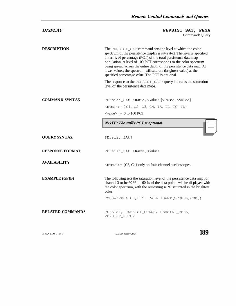
Remote Control Commands and Queries
LTXXX-RCM-E Rev B ISSUED: January 2002 189
DISPLAY PERSIST_SAT, PESACommand/Query
DESCRIPTION ThePERSIST_SAT command sets the level at which the colorspectrum of the persistence display is saturated. The level is specifiedin terms of percentage (PCT) of the total persistence data mappopulation. A level of 100 PCT corresponds to the color spectrumbeing spread across the entire depth of the persistence data map. Atlower values, the spectrum will saturate (brightest value) at thespecified percentage value. The PCT is optional.
The response to thePERSIST_SAT? query indicates the saturationlevel of the persistence data maps.
COMMAND SYNTAX PErsist_SAt <trace>,<value> [< trace>,<value>]
<trace> : = C1, C2, C3, C4, TA, TB, TC, TD
<value> : = 0 to 100 PCT
NN OOTTEE :: The suffixPCT is optional.
QUERY SYNTAX PErsist_SAt?
RESPONSE FORMAT PErsist_SAt <trace>,<value>
AVAILABILITY<trace> : = C3, C4 only on four-channel oscilloscopes.
EXAMPLE (GPIB) The following sets the saturation level of the persistence data map forchannel 3 to be 60 % — 60 % of the data points will be displayed withthe color spectrum, with the remaining 40 % saturated in the brightestcolor:
CMD$=“PESA C3,60”: CALL IBWRT(SCOPE%,CMD$)
RELATED COMMANDS PERSIST, PERSIST_COLOR, PERSIST_PERS,PERSIST_SETUP

P A R T T W O : C O M M A N D S
190 ISSUED: January 2002 LTXXX-RCM-E Rev B
DISPLAY PERSIST_SETUP, PESUCommand/Query
DESCRIPTION ThePERSIST_SETUP command selects the persistence duration ofthe display, in seconds, in persistence mode. In addition, thepersistence can be set either to all traces or only the top two on thescreen.
ThePERSIST_SETUP? query indicates the current status of thepersistence.
COMMAND SYNTAX PErsist_SetUp <time>,<mode>
<time> : = 0.5, 1, 2, 5, 10, 20, infinite<mode> : = TOP2, ALL
QUERY SYNTAX PErsist_SetUp?
RESPONSE FORMAT PErsist_SetUp <time>,<mode>
EXAMPLE (GPIB) The following sets the variable persistence at 10 seconds on the top twotraces:
CMD$=“PESU 20,TOP2”: CALL IBWRT(SCOPE%,CMD$)
RELATED COMMANDS PERSIST, PERSIST_COLOR, PERSIST_PERS,PERSIST_SAT
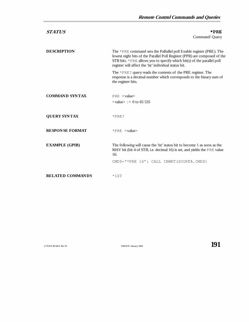
Remote Control Commands and Queries
LTXXX-RCM-E Rev B ISSUED: January 2002 191
STATUS *PRECommand/Query
DESCRIPTION The*PRE command sets the PaRallel poll Enable register (PRE). Thelowest eight bits of the Parallel Poll Register (PPR) are composed of theSTB bits. *PRE allows you to specify which bit(s) of the parallel pollregister will affect the ‘ist’ individual status bit.
The*PRE? query reads the contents of the PRE register. Theresponse is a decimal number which corresponds to the binary sum ofthe register bits.
COMMAND SYNTAX PRE <value>
<value> : = 0 to 65 535
QUERY SYNTAX *PRE?
RESPONSE FORMAT *PRE <value>
EXAMPLE (GPIB) The following will cause the ‘ist’ status bit to become 1 as soon as theMAV bit (bit 4 of STB, i.e. decimal 16) is set, and yields thePRE value16:
CMD$=“*PRE 16”: CALL IBWRT(SCOPE%,CMD$)
RELATED COMMANDS *IST

P A R T T W O : C O M M A N D S
192 ISSUED: January 2002 LTXXX-RCM-E Rev B
PROBES PROBE_CAL?, PRCA?Query
DESCRIPTION ThePROBE_CAL? query performs a complete auto-calibrationof a current probe connected to your Waverunner oscilloscope.At the end of this calibration, the response indicates howthecalibration has terminated, and the oscilloscope then returns tothe state it was in prior to the query.
QUERY SYNTAX <channel> : PROBE_CAL?
RESPONSE FORMAT PROBE_CAL <diagnostics>
<diagnostics> : = 0 or 1
0 = Calibration successful
EXAMPLE (GPIB) The following forces a self-calibration:
CMD$=“PROBE_CAL?”: CALLIBWRT(SCOPE%,CMD$):
CALL IBRD(SCOPE%,RD$): PRINT RD$
Response message (if no failure): PROBE_CAL 0
RELATED COMMANDS AUTO_CALIBRATE, *CAL?, PROBE_DEGAUSS?

Remote Control Commands and Queries
LTXXX-RCM-E Rev B ISSUED: January 2002 193
PROBES PROBE_DEGAUSS?, PRDG?Query
DESCRIPTION ThePROBE_DEGAUSS? query performs the automatic degaussingof the current probe connected to your Waverunner oscilloscope. Thiseliminates core saturation by use of a backing current and applicationof an alternating field, reduced in amplitude over time from an initialhigh value. After the degaussing, a probe calibration is performed.
QUERY SYNTAX <channel> : PROBE_DEGAUSS?
RESPONSE FORMAT PROBE_DEGAUSS <diagnostics>
<diagnostics> : = 0 or 1
0 = Degaussing and calibration successful
(Note: If coupling is not DC, probe calibration will not be performed,and the <diagnostics> response will be 1.)
EXAMPLE (GPIB) The following degausses and calibrates the connected probe:
CMD$=“PROBE_DEGAUSS?”: CALLIBWRT(SCOPE%,CMD$):
CALL IBRD(SCOPE%,RD$): PRINT RD$
Response message (if no failure):
PROBE_DEGAUSS 0
RELATED COMMANDS PROBE_CAL?, PROBE_NAME?

P A R T T W O : C O M M A N D S
194 ISSUED: January 2002 LTXXX-RCM-E Rev B
PROBES PROBE_NAME?, PRNA?Query
DESCRIPTION ThePROBE_NAME? query returns the name of a probe connected toyour Waverunner oscilloscope. Passive probes are identified by theirattenuation factor.
QUERY SYNTAX <channel> : PROBE_NAME?
RESPONSE FORMAT PROBE_NAME <name>
<diagnostics> : = 0 or 1
0 = successful
EXAMPLE (GPIB) The following obtains an identification of the connected probe:
CMD$=“PROBE_NAME?”: CALL IBWRT(SCOPE%,CMD$):
CALL IBRD(SCOPE%,RD$): PRINT RD$
RELATED COMMANDS PROBE_CAL?, PROBE_DEGAUSS?

Remote Control Commands and Queries
LTXXX-RCM-E Rev B ISSUED: January 2002 195
SAVE/RECALL SETUP *RCLCommand
DESCRIPTION The*RCL command sets the state of your Waverunneroscilloscope, using one of the five non-volatile panel setups, byrecalling the complete front panel setup of the oscilloscope. Panelsetup 0 corresponds to the default panel setup.
The*RCL command produces an effect the opposite of the *SAVcommand.
If the desired panel setup is not acceptable, the EXecution errorstatus Register (EXR) is set and the EXE bit of the standard EventStatus Register (ESR) is set.
COMMAND SYNTAX *RCL <panel_setup>
<panel_setup> : = 0 to 4
EXAMPLE (GPIB) The following recalls your Waverunner oscilloscope setup previouslystored in panel setup 3:
CMD$=“*RCL 3”: CALL IBWRT(SCOPE%,CMD$)
RELATED COMMANDS PANEL_SETUP, *SAV, EXR

P A R T T W O : C O M M A N D S
196 ISSUED: January 2002 LTXXX-RCM-E Rev B
MISCELLANEOUS REAR_OUTPUT, ROUTCommand/Query
DESCRIPTION TheREAR_OUTPUT command is used to set the type of signal put outat the Waverunner rear panel BNC connector. TheREAR_OUTPUT?Query returns the current mode of the connector.
COMMAND SYNTAX Rear_OUTput <mode>[,<level>[,<rate>]]
<mode> : = OFF, PF, TRIG, TRDY, PULSE
QUERY SYNTAX Rear_OUTput?
RESPONSE FORMAT Rear_OUTput <mode>,<level>[,<rate>]
EXAMPLE (GPIB) The following turns off the BNC rear output:
CMD$=“ROUT OFF”:
CALL IBWRT(SCOPE%,CMD$)
RELATED COMMANDS PASS_FAIL_DO, CAL_OUTPUT
ADDITIONAL INFORMATION
NOTATION
OFF Turns off rear output
PF PASS/FAIL mode
PULSE Provides a single pulse
TRIG Trigger Out mode
TRDY Trigger is ready for a newacquisition

Remote Control Commands and Queries
LTXXX-RCM-E Rev B ISSUED: January 2002 197
WAVEFORM TRANSFER RECALL, RECCommand
DESCRIPTION The RECALL command recalls a waveform file from the currentdirectory on mass storage into any or all of the internal memories M1to M4.
NN OOTTEE :: only waveforms stored in BINARY format can berecalled.
COMMAND SYNTAX <memory> : RECall DISK,<device>,FILE,‘<filename>’
<memory> : = M1, M2, M3, M4, ALL<device> : = CARD, FLPY, HDD<filename> : = An alphanumeric string of up to eight characters,followed by a dot and an extension of up to three digits.
AVAILABILITY<device> : CARD only available with Memory Card option installed.
<device> : HDD only available with removable Hard Disk optioninstalled.
EXAMPLE (GPIB) The following recalls a waveform file called “SC1.001” from thememory card into Memory M1:
CMD$=“M1:REC DISK,CARD,FILE,‘SC1.001’”: CALLIBWRT(SCOPE%,CMD$)
RELATED COMMANDS STORE, INR?
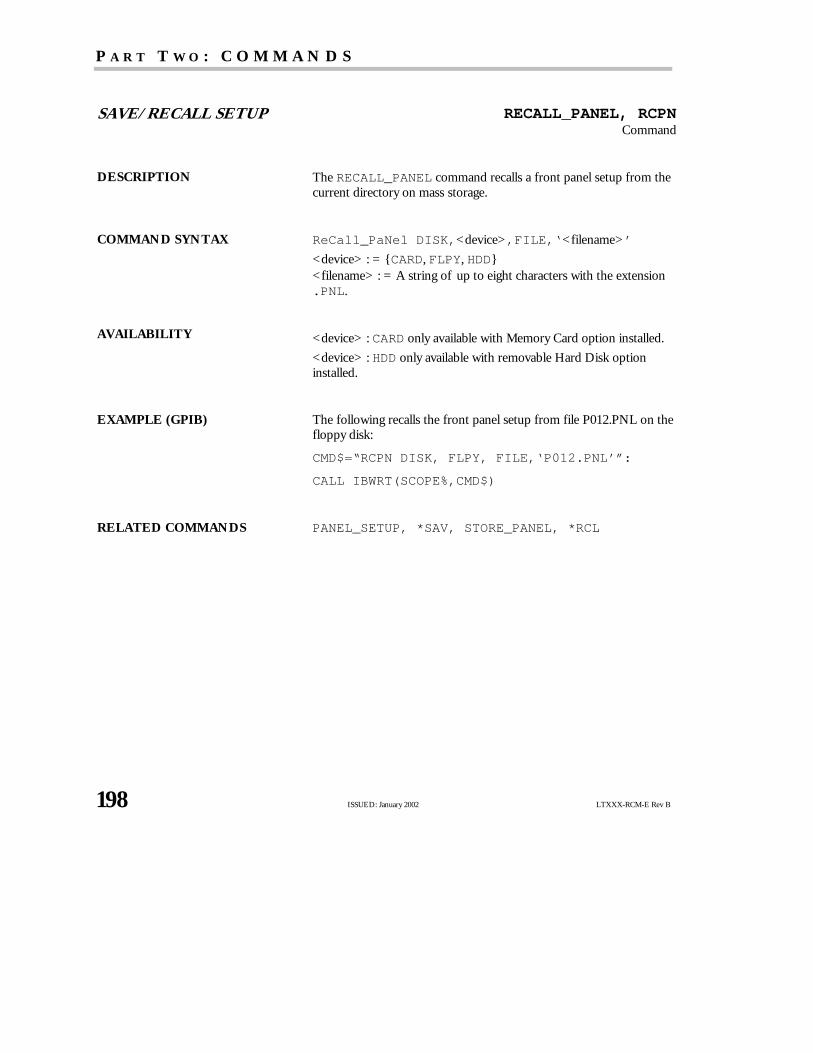
P A R T T W O : C O M M A N D S
198 ISSUED: January 2002 LTXXX-RCM-E Rev B
SAVE/RECALL SETUP RECALL_PANEL, RCPNCommand
DESCRIPTION TheRECALL_PANEL command recalls a front panel setup from thecurrent directory on mass storage.
COMMAND SYNTAX ReCall_PaNel DISK,<device>,FILE,‘<filename>’
<device> : = CARD, FLPY, HDD<filename> : = A string of up to eight characters with the extension.PNL.
AVAILABILITY <device> : CARD only available with Memory Card option installed.
<device> : HDD only available with removable Hard Disk optioninstalled.
EXAMPLE (GPIB) The following recalls the front panel setup from file P012.PNL on thefloppy disk:
CMD$=“RCPN DISK, FLPY, FILE,‘P012.PNL’”:
CALL IBWRT(SCOPE%,CMD$)
RELATED COMMANDS PANEL_SETUP, *SAV, STORE_PANEL, *RCL

Remote Control Commands and Queries
LTXXX-RCM-E Rev B ISSUED: January 2002 199
SAVE/RECALL SETUP *RSTCommand
DESCRIPTION The*RST command initiates a device reset. *RST sets all eight tracesto the GND line and recalls the default setup.
COMMAND SYNTAX *RST
EXAMPLE (GPIB) The following resets the oscilloscope:
CMD$=“*RST”: CALL IBWRT(SCOPE%,CMD$)
RELATED COMMANDS *CAL, *RCL

P A R T T W O : C O M M A N D S
200 ISSUED: January 2002 LTXXX-RCM-E Rev B
ACQUISITION SAMPLE_CLOCK, SCLKCommand/Query
DESCRIPTION TheSAMPLE_CLOCK command allows you to control an externaltimebase. Set the number of data points that will be acquired when yourWaverunner oscilloscope is using the external clock. When the optionalsuffix NUM is used with the query, the response will be returned instandard numeric format.
COMMAND SYNTAX Sample_CLocK <state>[,<recordlength>][,<coupling>]
<state> : = INT, ECL, LV0, TTL
<recordlength> : = 10e+3, 10.0e+3, 11e+3… , for example,in standard numeric format.
Or, alternatively:= 50, 100, 200, 500, 1K, 2K, 5K, 10K, 20K, 50K, 100K,200K, 500K, 1M, 2M
However, values not absolutely identical to those listed immediatelyabove will be recognized by the scope as numerical data (see the tableunder this heading in Chapter 1). For example, the scope will recognize1.0M as 1 millisample. But it will recognize1.0MA as 1 megasample.
<coupling> : = D1M or D50
TTIIPP:: You cannot have the record length larger than the maximumavailable memory of your oscilloscope. Waverunner will adapt tothe closest valid <recordlength>. See the Operator’s Manual formaximums.
QUERY SYNTAX Sample_CLocK? [NUM]
RESPONSE FORMAT Sample_CLocK <state>,<recordlength>
EXAMPLE The following sets the oscilloscope to use the external clock with 1000-data-point records.
CMD$=“SCLK ECL,1000”: CALL IBWRT(SCOPE%,CMD$)

Remote Control Commands and Queries
LTXXX-RCM-E Rev B ISSUED: January 2002 201
SAVE/RECALL SETUP *SAVCommand
DESCRIPTION The*SAV command stores the current state of your Waverunneroscilloscope in non-volatile internal memory. The *SAV commandstores the complete front panel setup of the oscilloscope at the timethe command is issued.
NN OOTTEE :: Neither communication parameters (those modified bythe commands COMM_FORMAT, COMM_HEADER, COMM_HELP,COMM_ORDER and WAVEFORM_SETUP), nor enable registers ofthe status reporting system (*SRE, *PRE, *ESE, INE), are savedwhen*SAV is used.
COMMAND SYNTAX *SAV <panel_setup>
<panel_setup> : = 1 to 4
EXAMPLE (GPIB) The following saves the current Waverunner oscilloscope setup inpanel setup 3:
CMD$=“*SAV 3”: CALL IBWRT(SCOPE%,CMD$)
RELATED COMMANDS PANEL_SETUP, *RCL

P A R T T W O : C O M M A N D S
202 ISSUED: January 2002 LTXXX-RCM-E Rev B
HARD COPY SCREEN_DUMP, SCDPCommand/Query
DESCRIPTION TheSCREEN_DUMP command causes the oscilloscope to dump thescreen contents onto the hardcopy device. This command will haltyour Waverunner oscilloscope’s activities.
The time/date stamp which appears on the print-out corresponds tothe time at which the command was executed.
COMMAND SYNTAX SCreen_DumP
QUERY SYNTAX SCreen_DumP?
RESPONSE FORMAT SCreen_DumP <status>
<status> : = OFF
EXAMPLE (GPIB) The following initiates a screen dump:
CMD$=“SCDP”: CALL IBWRT(SCOPE%,CMD$)
RELATED COMMANDS INR, HARDCOPY_SETUP, HARDCOPY_TRANSMIT

Remote Control Commands and Queries
LTXXX-RCM-E Rev B ISSUED: January 2002 203
DISPLAY SCREEN_SAVE, SCSVCommand/Query
DESCRIPTION TheSCREEN_SAVE command controls the automatic Screen Saver,which automatically shuts down the internal color monitor after apreset time.
The response to theSCREEN_SAVE? query indicates whether theautomatic screen saver feature is on or off.
NN OOTTEE :: When the screen save is in effect, the oscilloscope is stillfully functional.
COMMAND SYNTAX SCreen_SaVe <enabled>
<enabled> : = YES, NO
QUERY SYNTAX SCreen_SaVe?
RESPONSE FORMAT SCreen_SaVe <state>
EXAMPLE (GPIB) The following enables the automatic screen saver:
CMD$=“SCSV YES”: CALL IBWRT(SCOPE%,CMD$)

P A R T T W O : C O M M A N D S
204 ISSUED: January 2002 LTXXX-RCM-E Rev B
DISPLAY SELECT, SELCommand/Query
DESCRIPTION TheSELECT command selects the specified trace for manual displaycontrol. An environment error (see table on page 124) is generated ifthe specified trace is not displayed.
TheSELECT? query returns the selection status of the specifiedtrace.
COMMAND SYNTAX <trace> : SELect
<trace> : = TA, TB, TC, TD
QUERY SYNTAX <trace> : SELect?
RESPONSE FORMAT <trace> : SELect <mode>
<mode> : = ON, OFF
EXAMPLE (GPIB) The following selects Trace B (TB):
CMD$=“TB:SEL”: CALL IBWRT(SCOPE%,CMD$)
RELATED COMMANDS TRACE

Remote Control Commands and Queries
LTXXX-RCM-E Rev B ISSUED: January 2002 205
ACQUISITION SEQUENCE, SEQCommand/Query
DESCRIPTION TheSEQUENCE command sets the conditions for the sequencemode acquisition. The response to theSEQUENCE? query gives theconditions for the sequence mode acquisition. The argument<max_size> can be expressed either as numeric fixed point,exponential or using standard suffixes. When the optional suffix NUMis used with the query, the response will be returned in standardnumeric format.
COMMAND SYNTAX SEQuence <mode>[,<segments>[,<max_size>]]
<mode> : = OFF, ON
<segments> : = the right-hand column in the table below:
M AX. M E M O R Y L E N GT H
PE R CH AN N E L
M AX. N U M B E R O F
SE GM E N T S
10 000 50
25 000 50
50 000 200
100 000 500
200 000 500
250 000 500
500 000 2000
1 000 000 2000
2 000 000 2000
<max_size> : = …10e+3, 10.0e+3,…11e+3,… , for example, instandard numeric format.

P A R T T W O : C O M M A N D S
206 ISSUED: January 2002 LTXXX-RCM-E Rev B
Or, alternatively:
= 50, 100, 250, 500, 1000, 2500, 5K, 10K, 25K, 50K, 100K,250K, 500K, 1M
However, values not absolutely identical to those listed immediatelyabove will be recognized by the scope as numerical data (see the tableunder this heading in Chapter 1). For example, the scope will recognize1.0M as 1 millisample. But it will recognize 1.0MA as 1 megasample.
NN OOTTEE :: The oscilloscope will adapt the requested <max_size> tothe closest valid value.
QUERY SYNTAX SEQuence? [NUM]
RESPONSE FORMAT SEQuence <mode>,<segments>,<max_size>
<mode> : = ON, OFF
EXAMPLE (GPIB) The following sets the segment count to 43, the maximum segment sizeto 250 samples, and turns the sequence mode ON:
CMD$=“SEQ ON,43,250”: CALL IBWRT(SCOPE%,CMD$)
RELATED COMMANDS TRIG_MODE

Remote Control Commands and Queries
LTXXX-RCM-E Rev B ISSUED: January 2002 207
MISCELLANEOUS SLEEPCommand
DESCRIPTION The SLEEP command makes the scope’s remote commandinterpreter wait the time specified in the argument before interpretingany remote commands that follow. It is typically used to let anexternal signal settle before the scope performs newacquisitions andprocessing defined by the remote commands that follow.
COMMAND SYNTAX SLEEP <n>
<n> : = time in seconds (0 to 1000.0)
EXAMPLE (GPIB) The following command causes the scope to sleep for 3.2 seconds.
CMSD$=“SLEEP 3.2”;: CALL IBWRT(SCOPE%,CMD$)
RELATED COMMANDS *TRG,WAIT

P A R T T W O : C O M M A N D S
208 ISSUED: January 2002 LTXXX-RCM-E Rev B
STATUS *SRECommand/Query
DESCRIPTION The*SRE command sets the Service Request Enable register (SRE).This command allows you to specify which summary message bit orbits in the STB register will generate a service request. Refer to thetable on page 210 for an overviewof the available summary messages.
A summary message bit is enabled by writing a ‘1’ into thecorresponding bit location. Conversely, writing a ‘0’ into a given bitlocation prevents the associated event from generating a servicerequest (SRQ). Clearing the SRE register disables SRQ interrupts.
The *SRE? query returns a value that, when converted to a binarynumber, represents the bit settings of the SRE register. Note that bit 6(MSS) cannot be set and its returned value is always zero.
COMMAND SYNTAX *SRE <value>
<value> : = 0 to 255
QUERY SYNTAX *SRE?
RESPONSE FORMAT *SRE <value>
EXAMPLE (GPIB) The following allows an SRQ to be generated as soon as the MAVsummary bit (bit 4, i.e. decimal 16) or the INB summary bit (bit 0, i.e.decimal 1) in the STB register, or both, are set. Summing these twovalues yields the SRE mask 16+1 = 17.
CMD$=“*SRE 17”: CALL IBWRT(SCOPE%,CMD$)

Remote Control Commands and Queries
LTXXX-RCM-E Rev B ISSUED: January 2002 209
STATUS *STB?Query
DESCRIPTION The*STB? query reads the contents of the 488.1 defined statusregister (STB), and the Master Summary Status (MSS). Theresponse represents the values of bits 0 to 5 and 7 of the StatusByte register and the MSS summary message.
The response to a *STB? query is identical to the response of aserial poll except that the MSS summary message appears in bit 6in place of the RQS message. Refer to the table on page 210 forfurther details of the status register structure.
QUERY SYNTAX *STB?
RESPONSE FORMAT *STB <value>
<value> : = 0 to 255
EXAMPLE (GPIB) The following reads the status byte register:
CMD$=“*STB?”: CALL IBWRT(SCOPE%,CMD$):
CALL IBRD(SCOPE%,RSP$): PRINT RSP$
Response message:
*STB 0
RELATED COMMANDS ALL_STATUS, *CLS, *PRE, *SRE
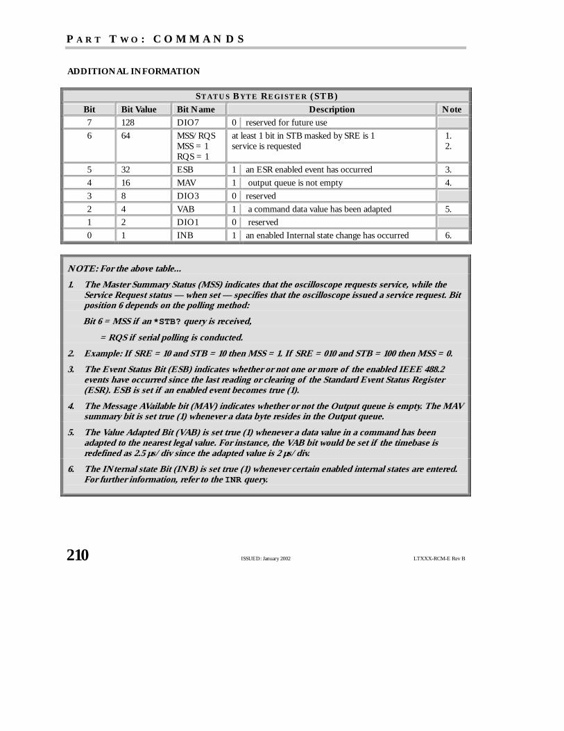
P A R T T W O : C O M M A N D S
210 ISSUED: January 2002 LTXXX-RCM-E Rev B
ADDITIONAL INFORMATION
ST AT U S B YT E R E GI ST E R (ST B )
Bit Bit Value Bit Name Description Note
7 128 DIO7 0 reserved for future use
6 64 MSS/RQSMSS = 1RQS = 1
at least 1 bit in STB masked by SRE is 1service is requested
1.2.
5 32 ESB 1 an ESR enabled event has occurred 3.
4 16 MAV 1 output queue is not empty 4.
3 8 DIO3 0 reserved
2 4 VAB 1 a command data value has been adapted 5.
1 2 DIO1 0 reserved
0 1 INB 1 an enabled Internal state change has occurred 6.
NN OOTTEE :: For the above table...
1. The Master Summary Status (MSS) indicates that the oscilloscope requests service, while theService Request status — when set — specifies that the oscilloscope issued a service request. Bitposition 6 depends on the polling method:
Bit 6 = MSS if an*STB? query is received,
= RQS if serial polling is conducted.
2. Example: If SRE = 10 and STB = 10 then MSS = 1. If SRE = 010 and STB = 100 then MSS = 0.
3. The Event Status Bit (ESB) indicates whether or not one or more of the enabled IEEE 488.2events have occurred since the last reading or clearing of the Standard Event Status Register(ESR). ESB is set if an enabled event becomes true (1).
4. The Message AVailable bit (MAV) indicates whether or not the Output queue is empty. The MAVsummary bit is set true (1) whenever a data byte resides in the Output queue.
5. The Value Adapted Bit (VAB) is set true (1) whenever a data value in a command has beenadapted to the nearest legal value. For instance, the VAB bit would be set if the timebase isredefined as 2.5 µs/div since the adapted value is 2 µs/div.
6. The INternal state Bit (INB) is set true (1) whenever certain enabled internal states are entered.For further information, refer to the INR query.

Remote Control Commands and Queries
LTXXX-RCM-E Rev B ISSUED: January 2002 211
ACQUISITION STOPCommand
DESCRIPTION TheSTOP command immediately stops the acquisition of a signal. Ifthe trigger mode is AUTO or NORM, STOP will place theoscilloscope in STOPPED trigger mode to prevent furtheracquisition.
COMMAND SYNTAX STOP
EXAMPLE The following stops the acquisition process:
CMD$ =“STOP”: CALL IBWRT(SCOPE%,CMD$)
RELATED COMMANDS ARM_ACQUISITION, TRIG_MODE, WAIT

P A R T T W O : C O M M A N D S
212 ISSUED: January 2002 LTXXX-RCM-E Rev B
WAVEFORM TRANSFER STORE, STOCommand
DESCRIPTION TheSTORE command stores the contents of the specified traceinto one of the internal memories M1 to M4 or to the currentdirectory on mass storage.
COMMAND SYNTAX STOre [< trace>,<dest>]
<trace> : = TA, TB, TC, TD, C1, C2, C3, C4, ALL_DISPLAYED
<dest> : = M1, M2, M3, M4, CARD, FLPY, HDD
TIP: If you send the STORE command without an argument,all traces currently enabled in the Store Setup will be stored.Modify this setup using STORE_SETUP.
AVAILABILITY<trace> : = C3, C4 only available on four-channel oscilloscopes.
<dest> : CARD only available with Memory Card option installed.
<dest> : HDD only available with removable Hard Disk optioninstalled.
EXAMPLE (GPIB) The following stores the contents of Trace A (TA) into Memory 1(M1):
CMD$=“STO TA,M1”: CALL IBWRT(SCOPE%,CMD$)
The following stores all currently displayed waveforms onto thememory card:
CMD$=“STO ALL_DISPLAYED, CARD”:
CALL IBWRT(SCOPE%,CMD$)
The following executes the storage operation currently defined inthe Storage Setup (see command STORE_SETUP):
CMD$=“STO”: CALL IBWRT(SCOPE%,CMD$)
RELATED COMMANDS STORE_SETUP, RECALL
Remote Control Commands and Queries
LTXXX-RCM-E Rev B ISSUED: January 2002 213
SAVE/RECALL SETUP STORE_PANEL, STPNCommand
DESCRIPTION TheSTORE_PANEL command stores the complete front panelsetup of your Waverunner oscilloscope, at the time the command isissued, into a file on the current directory on mass storage.
NN OOTTEE :: The communication parameters (the parameters modified by commands COMM_FORMAT,COMM_HEADER, COMM_HELP, COMM_ORDER and WAVEFORM_SETUP) and the enable registersassociated with the status reporting system (commands *SRE, *PRE, *ESE, INE) are not saved bythis command.
If no filename (or an empty string) is supplied, the oscilloscope generates a filename according to itsinternal rules.
COMMAND SYNTAX STore_PaNel DISK, <device>, FILE,‘<filename>’
<device> : = CARD, FLPY, HDD<filename> : = A string of up to eight characters with the extension.PNL.
AVAILABILITY <device> : CARD only available with Memory Card option installed.
<device> : HDD only available with removable Hard Disk optioninstalled.
EXAMPLE (GPIB) The following saves the current Waverunner oscilloscope setup tothe memory card in a file called “DIODE.PNL”:
CMD$=“STPN DISK, CARD, FILE,‘DIODE.PNL’”:
CALL IBWRT(SCOPE%,CMD$)
RELATED COMMANDS PNSU, *SAV, RECALL_PANEL, *RCL

P A R T T W O : C O M M A N D S
214 ISSUED: January 2002 LTXXX-RCM-E Rev B
WAVEFORM TRANSFER STORE_SETUP, STSTCommand/Query
DESCRIPTION TheSTORE_SETUP command controls the way in which traces willbe stored. A single trace or all displayed traces can be enabled forstorage. This applies to both auto-storing and to theSTORE command.Traces can be auto-stored to mass storage after each acquisition untilthe mass storage device becomes full (FILL), or continuously (WRAP),replacing the oldest traces by newones.
TheSTORE_SETUP? query returns the current mode of operation ofAutostore, the current trace selection, and the current destination.
NN OOTTEE :: You can recall into the oscilloscope only waveformsstored in BINARY format.
COMMAND SYNTAX STore_SeTup [< trace> , <dest> ] [, AUTO, <mode>] [, FORMAT, < type> ]
<trace> : = TA, TB, TC, TD, C1, C2, C3, C4, ALL_DISPLAYED<dest> : = M1, M2, M3, M4, CARD, FLPY, HDD<mode> : = OFF, WRAP, FILL<type> : BINARY, SPREADSHEET, MATHCAD, MATLAB
QUERY SYNTAX STore_SeTup?
RESPONSE FORMAT STore_SeTup <trace>,<dest>,AUTO,<mode>
AVAILABILITY <trace> : = C3, C4 only available on four-channel oscilloscopes.
<dest> : CARD only available with Memory Card option installed.
<dest> : HDD only available with removable Hard Disk option installed.
EXAMPLE (GPIB) The following Channel 1 for storage. It enables an “autostore” to thecard until no more space is left on the memory card (AUTO, FILL).
CMD$=“STST C1, CARD, AUTO,FILL”:
CALL IBWRT(SCOPE%,CMD$)
RELATED COMMANDS STORE, INR

Remote Control Commands and Queries
LTXXX-RCM-E Rev B ISSUED: January 2002 215
WAVEFORM TRANSFER STORE_TEMPLATE, STTMCommand
DESCRIPTION TheSTORE_TEMPLATE command stores your Waverunneroscilloscope’s waveform template on a mass-storage device. Afilename is automatically generated in the form of LECROYvv.TPLwherevv is the two-digit revision number.
For example, for revision 2.1, the file name generated will beLECROY21.TPL.
See Chapter 4 for more on the waveform template, and Appendix IIfor a copy of the template itself.
COMMAND SYNTAX STore_TeMplate DISK,<device>
<device> : = CARD, FLPY, HDD
AVAILABILITY<device> : CARD only available with the Memory Card option installed.
<device> : HDD only available with removable Hard Disk optioninstalled.
EXAMPLE (GPIB) The following stores the current waveform template on the memorycard for future reference:
CMD$=“STTM DISK, CARD”: CALL IBWRT
(SCOPE%,CMD$)
RELATED COMMANDS TEMPLATE

P A R T T W O : C O M M A N D S
216 ISSUED: January 2002 LTXXX-RCM-E Rev B
MISCELLANEOUS TDISPCommand/Query
DESCRIPTION The TDISP command controls the presence and format of the timeand date display on the oscilloscope screen. The keywordCURRENT selects the current time and date for display. Thekeyword NONE removes both time and date. The keywordTRIGGER selects the trigger time of the uppermost waveformcurrently displayed.
COMMAND SYNTAX TDISP <state>
<state> : = CURRENT,NONE,TRIGGER
QUERY SYNTAX TDISP?
RESPONSE FORMAT TDISP <state>
EXAMPLE (GPIB) The following turns off the time and date display on the oscilloscopescreen:
CMD$=“TDISP NONE”: CALL IBWRT(SCOPE%,CMD$)

Remote Control Commands and Queries
LTXXX-RCM-E Rev B ISSUED: January 2002 217
WAVEFORM TRANSFER TEMPLATE?, TMPL?Query
DESCRIPTION TheTEMPLATE? query produces a copy of the template whichformally describes the various logical entities making up a completewaveform. In particular, the template describes in full detail thevariables contained in the descriptor part of a waveform.
See Chapter 4 for more on the waveform template, and Appendix IIfor a copy of the template itself.
QUERY SYNTAX TeMPLate?
RESPONSE FORMAT TeMPLate “<template>”
<template> : = A variable length string detailing the structure of awaveform.
RELATED COMMANDS INSPECT
P A R T T W O : C O M M A N D S
218 ISSUED: January 2002 LTXXX-RCM-E Rev B
ACQUISITION TIME_DIV, TDIVCommand/Query
DESCRIPTION TheTIME_DIV command modifies the timebase setting. The newtimebase setting can be specified with suffixes: NS for nanoseconds,US for microseconds, MS for milliseconds, S for seconds, or KS forkiloseconds. An out-of-range value causes the VAB bit (bit 2) in theSTB register (see table on page 210) to be set.
TheTIME_DIV? query returns the current timebase setting.
COMMAND SYNTAX Time_DIV <value>
<value> : = See the Operator’s Manual for specifications.
The suffix S (seconds) is optional.
QUERY SYNTAX Time_DIV?
RESPONSE FORMAT Time_DIV <value>
EXAMPLE (GPIB) The following sets the time base to 500 µsec/div:
CMD$=“TDIV 500US”: CALL IBWRT(SCOPE%,CMD$)
The following sets the time base to 2 msec/div:
CMD$=“TDIV 0.002”: CALL IBWRT(SCOPE%,CMD$)
RELATED COMMANDS TRIG_DELAY, TRIG_MODE

Remote Control Commands and Queries
LTXXX-RCM-E Rev B ISSUED: January 2002 219
DISPLAY TRACE, TRACommand/Query
DESCRIPTION TheTRACE command enables or disables the display of a trace. Anenvironment error (see table on page 124) is set if an attempt is madeto display more than four waveforms.
TheTRACE? query indicates whether the specified trace is displayedor not.
COMMAND SYNTAX <trace> : TRAce <mode>
<trace> : = C1, C2, C3, C4, TA, TB, TC, TD<mode> : = ON, OFF
QUERY SYNTAX <trace> : TRAce?
RESPONSE FORMAT <trace> : TRAce <mode>
AVAILABILITY<trace> : = C3, C4 only on four-channel Waverunner oscilloscopes.
EXAMPLE (GPIB) The following displays Trace A (TA):
CMD$=“TA:TRA ON”: CALL IBWRT(SCOPE%,CMD$)

P A R T T W O : C O M M A N D S
220 ISSUED: January 2002 LTXXX-RCM-E Rev B
DISPLAY TRACE_OPACITY, TOPACommand/Query
DESCRIPTION TheTRACE_OPACITY command controls the opacity and thetransparency of the trace color. The trace can be made either opaque(traces will overwrite and obscure each other) or transparent(overlapping traces can be distinguished from one another).
The response to theTRACE_OPACITY? query indicates whetherthe traces are opaque or transparent.
COMMAND SYNTAX Trace_OPAcity <type>
<type> : = OPAQUE, TRANSPARENT
QUERY SYNTAX Trace_OPAcity?
RESPONSE FORMAT Trace_OPAcity <type>
EXAMPLE (GPIB) The following allows traces to be distinguished even when they overlap:
CMD$=“TOPA TRANSPARENT”: CALLBWRT(SCOPE%,CMD$)

Remote Control Commands and Queries
LTXXX-RCM-E Rev B ISSUED: January 2002 221
ACQUISITION *TRGCommand
DESCRIPTION The*TRG command executes an ARM command. *TRG is theequivalent of the 488.1 GET (Group Execute Trigger) message.
COMMAND SYNTAX *TRG
EXAMPLE (GPIB) The following enables signal acquisition:
CMD$=“*TRG”: CALL IBWRT(SCOPE%,CMD$)
RELATED COMMANDS ARM_ACQUISITION, STOP, WAIT

P A R T T W O : C O M M A N D S
222 ISSUED: January 2002 LTXXX-RCM-E Rev B
ACQUISITION TRIG_COUPLING, TRCPCommand/Query
DESCRIPTION TheTRIG_COUPLING command sets the coupling mode of thespecified trigger source.
TheTRIG_COUPLING? query returns the trigger coupling of theselected source.
NN OOTTEE :: The oscilloscope automatically determines triggerslope when in HFDIV coupling. The TRIG_SLOPE commandis not used in HFDIV coupling mode.
HFDIV is indicated as HF in the trigger setup menus.
COMMAND SYNTAX <trig_source> : TRig_CouPling <trig_coupling>
<trig_source> : = C1, C2, C3, C4, EX, EX10<trig_coupling> : = AC, DC, HFREJ, LFREJ
QUERY SYNTAX <trig_source> : TRig_CouPling?
RESPONSE FORMAT <trig_source> : TRig_CouPling <trig_coupling>
AVAILABILITY <trig_source> : = C3, C4 only on four-channel Waverunneroscilloscopes.
EXAMPLE (GPIB) The following sets the coupling mode of the trigger source Channel2 to AC:
CMD$=“C2:TRCP AC”: CALL IBWRT(SCOPE%,CMD$)
RELATED COMMANDS TRIG_COUPLING, TRIG_DELAY, TRIG_LEVEL,TRIG_MODE, TRIG_SELECT, TRIG_SLOPE,TRIG_WINDOW

Remote Control Commands and Queries
LTXXX-RCM-E Rev B ISSUED: January 2002 223
ACQUISITION TRIG_DELAY, TRDLCommand/Query
DESCRIPTION TheTRIG_DELAY command sets the time at which the trigger is tooccur in respect of the first acquired data point (displayed at the left-hand edge of the screen).
Positive trigger delays are to be expressed as a percentage of the fullhorizontal screen. This mode is called pre-trigger acquisition, as dataare acquired before the trigger occurs. Negative trigger delays mustbe given in seconds. This mode is called post-trigger acquisition, asthe data are acquired after the trigger has occurred.
If a value outside the range −10 000 div × time/div and 100 % isspecified, the trigger time will be set to the nearest limit and the VABbit (bit 2) will be set in the STB register.
The response to theTRIG_DELAY? query indicates the trigger timewith respect to the first acquired data point. Positive times areexpressed as a percentage of the full horizontal screen and negativetimes in seconds.
COMMAND SYNTAX TRig_DeLay <value>
<value> : = 0.00 PCT to 100.00 PCT (pretrigger)
−20 PS to −10 MAS (post-trigger)
NN OOTTEE :: The suffix is optional. For positive numbers the suffixPCT is assumed. For negative numbersthe suffixS is assumed. MAS is the suffix for Ms (megaseconds), useful only for extremely large delaysat very slow timebases.

P A R T T W O : C O M M A N D S
224 ISSUED: January 2002 LTXXX-RCM-E Rev B
QUERY SYNTAX TRig_DeLay?
RESPONSE FORMAT TRig_DeLay <value>
EXAMPLE (GPIB) The following sets the trigger delay to −20 s (post-trigger):
CMD$=“TRDL −20S”: CALL IBWRT(SCOPE%,CMD$)
RELATED COMMANDS TIME_DIV, TRIG_COUPLING, TRIG_LEVEL,TRIG_MODE, TRIG_SELECT, TRIG_SLOPE,TRIG_WINDOW

Remote Control Commands and Queries
LTXXX-RCM-E Rev B ISSUED: January 2002 225
ACQUISITION TRIG_LEVEL, TRLVCommand/Query
DESCRIPTION TheTRIG_LEVEL command adjusts the trigger level of thespecified trigger source. An out-of-range value will be adjusted to theclosest legal value and will cause the VAB bit (bit 2) in the STBregister to be set.
TheTRIG_LEVEL? query returns the current trigger level.
COMMAND SYNTAX <trig_source> : TRig_LeVel <trig_level>
<trig_source> : = C1, C2, C3, C4, EX, EX10<trig_level> : =
NN OOTTEE :: The suffixV is optional.
QUERY SYNTAX <trig_source> : TRig_LeVel?
RESPONSE FORMAT <trig_source> : TRig_LeVel <trig_level>
AVAILABILITY <trig_source> : = C3, C4 only on four-channel Waverunneroscilloscopes.
EXAMPLE (GPIB) The following adjusts the trigger level of Channel 2 to −3.4 V:
CMD$=“C2:TRLV −3.4V”: CALL IBWRT(SCOPE%,CMD$)
RELATED COMMANDS TRIG_COUPLING, TRIG_DELAY, TRIG_MODE,TRIG_SELECT, TRIG_SLOPE, TRIG_WINDOW

P A R T T W O : C O M M A N D S
226 ISSUED: January 2002 LTXXX-RCM-E Rev B
ACQUISITION TRIG_MODE, TRMDCommand/Query
DESCRIPTION TheTRIG_MODE command specifies the trigger mode.
TheTRIG_MODE? query returns the current trigger mode.
COMMAND SYNTAX TRig_MoDe <mode>
<mode> : = AUTO, NORM, SINGLE, STOP
QUERY SYNTAX TRig_MoDe?
RESPONSE FORMAT TRig_MoDe <mode>
EXAMPLE (GPIB) The following selects the normal mode:
CMD$=“TRMD NORM”: CALL IBWRT(SCOPE%,CMD$)
RELATED COMMANDS ARM_ACQUISITION, STOP, TRIG_SELECT, SEQUENCE,TRIG_COUPLING, TRIG_LEVEL, TRIG_SLOPE,TRIG_WINDOW

Remote Control Commands and Queries
LTXXX-RCM-E Rev B ISSUED: January 2002 227
ACQUISITION TRIG_SELECT, TRSECommand/Query
DESCRIPTION TheTRIG_SELECT command selects the condition that will triggerthe acquisition of waveforms. Depending on the trigger type,additional parameters must be specified. These additional parametersare grouped in pairs. The first in the pair names the variable to bemodified, while the second gives the newvalue to be assigned. Pairscan be given in any order and restricted to those variables to bechanged.
TheTRIG_SELECT? query returns the current trigger condition.
T R I GGE R N O T AT I O N
DROP Dropout QL Qualifier
EDGE Edge SNG Single source
EV Event SQ State-Qualified
GLIT Glitch SR Source
HT Hold type STD *Standard (Edge Trigger)
HV Hold value TEQ Edge-Qualified
HV2 Second hold value TI Time
IL Interval larger TL Time within
INTV Interval TV TV
IS Interval smaller CHAR Characteristics
I2 Interval-width window FLD Field
OFF No hold-off on wait FLDC Field count
PL Pulse larger ILAC Interlace
PS Pulse smaller LINE Line
P2 Pulse-width window LPIC Lines per picture
COMMAND SYNTAXFor all but TV Trigger TRig_SElect<trig_type>,SR,<source>,QL,<source>,
HT,<hold_type>,HV,<hold_value>,HV2,<hold value>
* HT and HV do not apply to the Standard Trigger.

P A R T T W O : C O M M A N D S
228 ISSUED: January 2002 LTXXX-RCM-E Rev B
<trig_type> : = DROP, EDGE, GLIT, INTV, STD, SNG, SQ,TEQ
<source> : = C1, C2, C3, C4, LINE, EX, EX10, PA
<hold_type> : = TI, TL, EV, PS, PL, IS, IL, P2, I2, OFF
<hold_value> : = See Operator’s Manual for valid values
NN OOTTEE :: The suffixS (seconds) is optional.
QUERY SYNTAX TRig_SElect?
RESPONSE FORMAT TRig_SElect<trig_type>,SR,<source>,HT,<hold_type>,HV,
<hold_value>,<hold_value>
HV2 only returned if <hold_type> is P2 or I2
AVAILABILITY<source> : C3, C4 only available on four-channel Waverunneroscilloscopes.
EXAMPLE (GPIB) The following selects the single-source trigger with Channel 1 as triggersource. Hold type and hold value are chosen as “pulse smaller” than20 ns:
CMD$=“TRSE SNG,SR,C1,HT,PS,HV,20 NS”:
CALL IBWRT(SCOPE%,CMD$)

Remote Control Commands and Queries
LTXXX-RCM-E Rev B ISSUED: January 2002 229
TV COMMAND SYNTAX TRig_SElect<trig_type>,SR,<source>,FLDC,<field_count>,FLD,<field>,CHAR,<characteristics>,LPIC,<lpic>,ILAC,<ilace>,LINE,<line>
<trig_type> : = TVP,TVN TVP=TV Pos, TVN=TV Neg
<source> : = C1, C2, C3, C4, NE, EX, EX10
<field_count> : = 1, 2
<field> : = 1 to field_count
<characteristics> : = NTSC, PALSEC, CUST50, CUST60
< lpic> : = 1 to 1500
<ilace> : = 1, 2
< line> : = 1 to 1500 or 0 for any line
The FLD value is interpreted with the current FLDC value. The LINEvalue is interpreted with the current FLD and CHAR values.
QUERY SYNTAX TRig_SElect?
RESPONSE FORMAT TRig_SElectTVP,SR,<source>,FLDC,<field_count>,FLD,<field>,
CHAR,<characteristic>,LINE,<line>
AVAILABILITY <source> : = C3, C4 only on four-channel Waverunneroscilloscopes.
EXAMPLE (GPIB) The following sets up the trigger system to trigger on the 3rd field, line17, of the eight-field PAL/SECAM TV signal applied to the externalinput.
CMD$=“TRSE TVN,SR,EX,FLDC,8,FLD,3,CHAR,PALSEC,
LINE,17”: CALL IBWRT(SCOPE%,CMD$)
RELATED COMMANDS TRIG_COUPLING, TRIG_DELAY, TRIG_LEVEL,TRIG_MODE, TRIG_SLOPE, TRIG_WINDOW

P A R T T W O : C O M M A N D S
230 ISSUED: January 2002 LTXXX-RCM-E Rev B
ACQUISITION TRIG_SLOPE, TRSLCommand/Query
DESCRIPTION TheTRIG_SLOPE command sets the trigger slope of the specifiedtrigger source. An environment error (see table on page 124) will begenerated when an incompatible TRSL order is received while thetrigger coupling is set to HFDIV (seeTRIG_COUPLING).
TheTRIG_SLOPE? query returns the trigger slope of the selectedsource.
COMMAND SYNTAX <trig_source> : TRig_SLope <trig_slope>
<trig_source> : = C1, C2, C3, C4, LINE, EX, EX10
<trig_slope> : = NEG, POS, WINDOW
QUERY SYNTAX <trig_source> : TRig_SLope?
RESPONSE FORMAT <trig_source> : TRig_SLope <trig_slope>
AVAILABILITY <trig_source> : = C3, C4 only available on four-channeloscilloscopes.
EXAMPLE (GPIB) The following sets the trigger slope of Channel 2 to negative:
CMD$=“C2:TRSL NEG”: CALL IBWRT(SCOPE%,CMD$)
RELATED COMMANDS TRIG_COUPLING, TRIG_DELAY, TRIG_LEVEL,TRIG_MODE, TRIG_SELECT, TRIG_SLOPE,TRIG_WINDOW
Remote Control Commands and Queries
LTXXX-RCM-E Rev B ISSUED: January 2002 231
ACQUISITION TRIG_WINDOW, TRWICommand/Query
DESCRIPTION The TRIG_WINDOW command sets the windowamplitude in voltson the current Edge trigger source. The windowis centered aroundthe Edge trigger level.
The TRIG_WINDOW? query returns the current windowamplitude.
COMMAND SYNTAX TRig_WIndow <value>
<value> : = 0 to 25 V (maximum range)
NN OOTTEE :: The suffixV is optional.
QUERY SYNTAX TRig_WIndow?
RESPONSE FORMAT TRig_WIndow <trig_level>
EXAMPLE The following adjusts the windowsize to +0.5 V:
CMD$=“TRWI 0.5V”: CALL IBWRT(SCOPE%,CMD$)
RELATED COMMANDS TRIG_COUPLING, TRIG_DELAY, TRIG_LEVEL,TRIG_MODE, TRIG_SELECT, TRIG_SLOPE

P A R T T W O : C O M M A N D S
232 ISSUED: January 2002 LTXXX-RCM-E Rev B
MISCELLANEOUS *TST?Query
DESCRIPTION The*TST? query performs an internal self-test, the responseindicating whether the self-test has detected any errors. The self-testincludes testing the hardware of all channels, the timebase and thetrigger circuits.
Hardware failures are identified by a unique binary code in thereturned <status> number. A “0” response indicates that no failuresoccurred.
QUERY SYNTAX *TST?
RESPONSE FORMAT *TST <status>
<status> : = 0 self-test successful
EXAMPLE (GPIB) The following causes a self-test to be performed:
CMD$=“*TST?”: CALL IBWRT(SCOPE%,CMD$):
CALL IBRD(SCOPE%,RD$): PRINT RD$
Response message (if no failure):
*TST 0
RELATED COMMANDS *CAL

Remote Control Commands and Queries
LTXXX-RCM-E Rev B ISSUED: January 2002 233
STATUS URR?Query
DESCRIPTION The URR? query reads and clears the contents of the User Requeststatus Register (URR). The URR register specifies which button inthe menu field was pressed.
In remote mode, the URR register indicates the last button waspressed, provided it was activated with a KEY command (see page154). In local mode, the URR register indicates whether the CALLHOST button has been pressed. If no menu button has been pressedsince the last URR? query, the value 0 is returned.
U SE R R E Q U E ST ST AT U S R E GI ST E R ST R U C T U R E (U R R )
Value Description
0 No button has been pressed
1 The top menu button has been pressed
2 The second-from-top menu button has been pressed
3 The third-from-top menu button has been pressed
4 The fourth-from-top menu button has been pressed
5 The fifth-from-top menu button has been pressed
100When the “Call Host” command is “On” (the bottom buttonfor the root, or primary, menu has been pressed)
QUERY SYNTAX URR?
RESPONSE FORMAT URR <value>
<value> : = 0 to 5, 100
EXAMPLE (GPIB) The following reads the contents of the URR register:
CMD$=“URR?”: CALL IBWRT(SCOPE%,CMD$):

P A R T T W O : C O M M A N D S
234 ISSUED: January 2002 LTXXX-RCM-E Rev B
CALL IBRD(SCOPE%,RSP$): PRINT RSP$
Response message:URR 0
RELATED COMMANDS CALL_HOST, KEY, ALL_STATUS, *CLS

Remote Control Commands and Queries
LTXXX-RCM-E Rev B ISSUED: January 2002 235
DISPLAY VERT_MAGNIFY, VMAGCommand/Query
DESCRIPTION TheVERT_MAGNIFY command vertically expands the specified trace.The command is executed even if the trace is not displayed.
The maximum magnification allowed depends on the number ofsignificant bits associated with the data of the trace.
TheVERT_MAGNIFY? query returns the magnification factor of thespecified trace.
COMMAND SYNTAX <trace> : Vert_MAGnify <factor>
<trace> : = TA, TB, TC, TD
<factor> : = 4.0E-3 to 50 (maximum)
QUERY SYNTAX <trace> : Vert_MAGnify?
RESPONSE FORMAT <trace> : Vert_MAGnify <factor>
EXAMPLE The following enlarges the vertical amplitude of Trace A by a factor of3.45 with respect to its original amplitude:
CMD$=“TA:VMAG 3.45”: CALL IBWRT(SCOPE%,CMD$)
RELATED COMMANDS VERT_POSITION

P A R T T W O : C O M M A N D S
236 ISSUED: January 2002 LTXXX-RCM-E Rev B
DISPLAY VERT_POSITION, VPOSCommand/Query
DESCRIPTION TheVERT_POSITION command adjusts the vertical position ofthe specified trace on the screen. It does not affect the original offsetvalue obtained at acquisition time.
TheVERT_POSITION? query returns the current vertical positionof the specified trace.
COMMAND SYNTAX <trace> : Vert_POSITION <display_offset>
<trace> : = TA, TB, TC, TD
<display_offset> : = −5900 to +5900 DIV
NN OOTTEE :: The suffixDIV is optional. The limits depend on thecurrent magnification factor, the number of grids on the display,and the initial position of the trace.
QUERY SYNTAX <trace> : Vert_POSition?
RESPONSE FORMAT <trace> : Vert_POSITION <display_offset>
EXAMPLE The following shifts Trace A (TA) upwards by +3 divisions relative tothe position at the time of acquisition:
CMD$=“TA:VPOS 3DIV”: CALL IBWRT(SCOPE%,CMD$)
RELATED COMMANDS VERT_MAGNIFY

Remote Control Commands and Queries
LTXXX-RCM-E Rev B ISSUED: January 2002 237
ACQUISITION VOLT_DIV, VDIVCommand/Query
DESCRIPTION TheVOLT_DIV command sets the vertical sensitivity in Volts/div.The VAB bit (bit 2) in the STB register (see table on page 210) is setif an out-of-range value is entered.
The probe attenuation factor is not taken into account for adjustingvertical sensitivity.
TheVOLT_DIV? query returns the vertical sensitivity of thespecified channel.
COMMAND SYNTAX <channel> : Volt_DIV <v_gain>
<channel> : = C1, C2, C3, C4<v_gain> : = See Operator’s Manual for specifications.
NN OOTTEE :: The suffixV is optional.
QUERY SYNTAX <channel> : Volt_DIV?
RESPONSE FORMAT <channel> : Volt_DIV <v_gain>
AVAILABILITY<channel> : = C3, C4 only available on four-channel oscilloscopes.
EXAMPLE The following sets the vertical sensitivity of channel 1 to 50 mV/div:
CMD$=“C1:VDIV 50MV”: CALL IBWRT(SCOPE%,CMD$)

P A R T T W O : C O M M A N D S
238 ISSUED: January 2002 LTXXX-RCM-E Rev B
STATUS *WAICommand
DESCRIPTION The*WAI (WAIt to continue) command, required by the IEEE488.2 standard, has no effect on the oscilloscope, as Waverunneronly starts processing a command when the previous command hasbeen entirely executed.
COMMAND SYNTAX *WAI
RELATED COMMANDS *OPC

Remote Control Commands and Queries
LTXXX-RCM-E Rev B ISSUED: January 2002 239
ACQUISITION WAITCommand
DESCRIPTION TheWAIT command prevents your Waverunner oscilloscope fromanalyzing newcommands until the oscilloscope has completed thecurrent acquisition. The optional argument specifies the timeout (inseconds) after which the scope will stop waiting for newacquisitions. If<t> is not given, or if <t> = 0.0, the scope will wait indefinitely.
COMMAND SYNTAX WAIT [<t>]
<t> :=timeout in seconds (0.0 to 1000.0, default is indefinite)
EXAMPLE (GPIB) send: “TRMD SINGLE”loop send:”ARM;WAIT;C1:PAVA?MAX”read responseprocess response
This example finds the maximum amplitudes of several signalsacquired one after another. ARM starts a newdata acquisition. TheWAIT command ensures that the maximum is evaluated for thenewly acquired waveform.
C1:PAVA?MAX instructs the oscilloscope to evaluate the maximumdata value in the Channel 1 waveform.
RELATED COMMANDS *TRG SLEEP

P A R T T W O : C O M M A N D S
240 ISSUED: January 2002 LTXXX-RCM-E Rev B
WAVEFORM TRANSFER WAVEFORM, WFCommand/Query
DESCRIPTION A WAVEFORM command transfers a waveform from the controller tothe oscilloscope, whereas a WAVEFORM? query transfers a waveformfrom the oscilloscope to the controller.
WAVEFORM stores an external waveform back into the oscilloscope’sinternal memory. A waveform consists of several distinct entities:
the descriptor (DESC)
the user text (TEXT)
the time (TIME) descriptor
the data (DAT1) block, and, optionally
a second block of data (DAT2).
See Chapter 4 for further information on waveform structure.
NN OOTTEE :: You can restore to the oscilloscope only completewaveforms queried with WAVEFORM? ALL.
TheWAVEFORM? query instructs the oscilloscope to transmit awaveform to the controller. The entities can be queried independently.If the “ALL” parameter is specified, all four or five entities aretransmitted in one block in the order enumerated above.
NN OOTTEE :: The format of the waveform data depends on the currentsettings specified by the last WAVEFORM_SETUP, COMM_ORDERand COMM_FORMAT commands.
COMMAND SYNTAX <memory> : WaveForm ALL <waveform_data_block>
<memory> : = M1, M2, M3, M4
<waveform_data_block> : = Arbitrary data block (see Chapter 5).

Remote Control Commands and Queries
LTXXX-RCM-E Rev B ISSUED: January 2002 241
QUERY SYNTAX <trace> : WaveForm? <block><trace> : = TA, TB, TC,TD, M1, M2, M3, M4, C1, C2, C3, C4
<block> : = DESC, TEXT, TIME, DAT1, DAT2, ALL
If you do not give a parameter, ALL will be assumed.
RESPONSE FORMAT <trace> : WaveForm <block>,<waveform_data_block>
TTIIPP:: It may be convenient to disable the response header if thewaveform is to be restored. See the COMM_HEADER command forfurther details.
AVAILABILITY<trace> : = C3, C4 only available on four-channel oscilloscopes.
EXAMPLES (GPIB) The following reads the block DAT1 from Memory 1 and saves it inthe file “MEM1.DAT”. The path header “M1:” is saved together withthe data.
FILE$ = “MEM1.DAT”CMD$ = “M1:WF? DAT1”CALL IBWRT(SCOPE%,CMD$)CALL IBRDF(SCOPE%,FILE$)
In the following example, the entire contents of Channel 1 are saved inthe file “CHAN1.DAT”. The path header “C1:” is skipped to ensurethat the data can later be recalled into the oscilloscope.
FILE$=“CHAN1.DAT”:RD$=SPACE$(3)CMD$=“CHDR SHORT; C1:WF?”CALL IBWRT(SCOPE%,CMD$)CALL IBRD(SCOPE%,RD$) Skip first 3 characters “C1:”CALL IBRDF(SCOPE%,FILE$) Save data in file “CHAN1.DAT”
The following illustrates howthe waveform data saved in the precedingexample can be recalled into Memory 1:
FILE$ = “CHAN1.DAT”CMD$ =“M1:”CALL IBEOT(SCOPE%,0)disable EOICALL IBWRT(SCOPE%,CMD$)CALL IBEOT(SCOPE%,1)re-enable EOICALL IBWRTF(SCOPE%,FILE$)

P A R T T W O : C O M M A N D S
242 ISSUED: January 2002 LTXXX-RCM-E Rev B
The “M1:” command ensures that the active waveform is “M1”.When the data file is sent to the oscilloscope, it first sees the header“WF” (the characters “C1:” having been skipped when reading thefile) and assumes the default destination “M1”.
RELATED COMMANDS INSPECT, COMM_FORMAT, COMM_ORDER,FUNCTION_STATE, TEMPLATE, WAVEFORM_SETUP,WAVEFORM_TEXT

Remote Control Commands and Queries
LTXXX-RCM-E Rev B ISSUED: January 2002 243
WAVEFORM TRANSFER WAVEFORM_SETUP, WFSUCommand/Query
DESCRIPTION The WAVEFORM_SETUP command specifies the amount of data ina waveform to be transmitted to the controller. The command controlsthe settings of the parameters listed below.
N O T AT I O N
FP first point NP number of points
SN segment number SP sparsing
Sparsing (SP): The sparsing parameter defines the interval between data points. Forexample:
SP = 0 sends all data points
SP = 1 sends all data points
SP = 4 sends every 4th data point
Number of points (NP): The number of points parameter indicates howmany points should betransmitted. For example:
NP = 0 sends all data points
NP = 1 sends 1 data point
NP = 50 sends a maximum of 50 data points
NP = 1001 sends a maximum of 1001 data points
First point (FP): The first point parameter specifies the address of the first data point tobe sent. For waveforms acquired in sequence mode, this refers to therelative address in the given segment. For example:
FP = 0 corresponds to the first data point
FP = 1 corresponds to the second data point
FP = 5000 corresponds to data point 5001

P A R T T W O : C O M M A N D S
244 ISSUED: January 2002 LTXXX-RCM-E Rev B
Segment number (SN): The segment number parameter indicates which segment should besent if the waveform was acquired in sequence mode. This parameter isignored for non-segmented waveforms. For example:
SN = 0 all segments
SN = 1 first segment
SN = 23 segment 23
TheWAVEFORM_SETUP? query returns the transfer parameterscurrently in use.
COMMAND SYNTAX WaveForm_SetUpSP,<sparsing>,NP,<number>,FP,<point>,SN,<segment>
NN OOTTEE :: After power-on, all values are set to 0 (i.e. entire waveforms will be transmitted withoutsparsing).
Parameters are grouped in pairs. The first of the pair names the variable to be modified, while thesecond gives the new value to be assigned. Pairs can be given in any order and restricted to thosevariables to be changed.
QUERY SYNTAX WaveForm_SetUp?
RESPONSE FORMAT WaveForm_SetUpSP,<sparsing>,NP,<number>,FP,<point> ,SN, <segment>
EXAMPLE (GPIB) The following instructs every 3rd data point (SP=3) starting at address200 to be transferred:
CMD$=“WFSU SP,3,FP,200”: CALLIBWRT(SCOPE%,CMD$)
RELATED COMMANDS INSPECT, WAVEFORM, TEMPLATE

Remote Control Commands and Queries
LTXXX-RCM-E Rev B ISSUED: January 2002 245
WAVEFORM TRANSFER WAVEFORM_TEXT, WFTXCommand/Query
DESCRIPTION TheWAVEFORM_TEXT command is used to document theconditions under which a waveform has been acquired. The textbuffer is limited to 160 characters.
TheWAVEFORM_TEXT? query returns the text section of thespecified trace.
COMMAND SYNTAX <trace> : WaveForm_TeXt ‘<text>’
<trace> : = TA, TB, TC, TD, M1, M2, M3, M4, C1, C2, C3,C4<text> : = An ASCII message (max. 160 characters long)
QUERY SYNTAX <trace> : WaveForm_TeXt?
RESPONSE FORMAT <trace> : WaveForm_TeXt “<text>“
AVAILABILITY<trace> : = C3, C4 only on four-channel Waverunner oscilloscopes.
EXAMPLE (GPIB) The following documents Trace A (TA):
MSG$= “‘Averaged pressure signal. Experimentcarried out Jan.15, 98’”
CMD$= “TA:WFTX”+ MSG$: CALL IBWRT(SCOPE%,CMD$)
RELATED COMMAND INSPECT, WAVEFORM, TEMPLATE

P A R T T W O : C O M M A N D S
246 ISSUED: January 2002 LTXXX-RCM-E Rev B
DISPLAY XY_ASSIGN?, XYAS?Query
DESCRIPTION TheXY_ASSIGN? query returns the traces currently assigned to theXY display. If there is no trace assigned to the X or Y axis the valueUNDEF will be returned instead of the trace name.
QUERY SYNTAX XY_ASsign?
RESPONSE FORMAT XY_ASsign <X_source>,<Y_source>
<X_source> : = UNDEF, TA, TB, TC, TD, C1, C2, C3, C4<Y_source> : = UNDEF, TA, TB, TC, TD, C1, C2, C3, C4
AVAILABILITY <X_source> : = C3, C4 only available on four-channel oscilloscopes.
<Y_source> : = C3, C4 only available on four-channel oscilloscopes.
EXAMPLE (GPIB) The following query finds the traces assigned to the X axis and theY axis respectively:
CMDS$=“XYAS?”: CALL IBWRT(SCOPE%,CMDS$)
Example of response message:
XYAS C1,C2
RELATED COMMANDS TRACE

Remote Control Commands and Queries
LTXXX-RCM-E Rev B ISSUED: January 2002 247
CURSOR XY_CURSOR_ORIGIN, XYCOCommand/Query
DESCRIPTION TheXY_CURSOR_ORIGIN command sets the position of theorigin for absolute cursor measurements on the XY display.
Absolute cursor values can be measured either with respect to thepoint (0,0) volts (OFF) or with respect to the center of the XY grid(ON).
TheXY_CURSOR_ORIGIN? query returns the current assignmentof the origin for absolute cursor measurements.
COMMAND SYNTAX XY_Cursor_Origin <mode>
<mode> : = ON, OFF
QUERY SYNTAX XY_Cursor_Origin?
RESPONSE FORMAT XY_Cursor_Origin <mode>
EXAMPLE (GPIB) The following sets the origin for absolute cursor measurements tothe center of the XY grid.
CMDS$=“XYCO ON”: CALL IBWRT(SCOPE%,CMDS$)
RELATED COMMANDS XY_CURSOR_VALUE

P A R T T W O : C O M M A N D S
248 ISSUED: January 2002 LTXXX-RCM-E Rev B
CURSOR XY_CURSOR_SET, XYCSCommand/Query
DESCRIPTION TheXY_CURSOR_SET command allows you to position any one ofthe six independent XY voltage cursors at a given screen location.The positions of the cursors can be modified or queried even if therequired cursor is not currently displayed or if the XY display modeis OFF.
TheXY_CURSOR_SET? query indicates the current position of thecursor or cursors.
TheCURSOR_SET command is used to position the time cursors.
N O T AT I O N
XABS vertical absolute on X axis
XREF vertical reference on X axis
XDIF vertical difference on X axis
YABS vertical absolute on Y axis
YREF vertical reference on Y axis
YDIF vertical difference on Y axis
COMMAND SYNTAX XY_Cursor_Set<cursor>,<position>[,<cursor>,<position>,...<cursor>,<position>]
<cursor> : = XABS, XREF, XDIF, YABS, YREF, YDIF
<position> : = −4 to 4 DIV
NN OOTTEE :: The suffixDIV is optional.
Parameters are grouped in pairs. The first of the pair names thecursor to be modified, while the second indicates its new value.Pairs can be given in any order and restricted to those items to bechanged.

Remote Control Commands and Queries
LTXXX-RCM-E Rev B ISSUED: January 2002 249
QUERY SYNTAX XY_Cursor_Set? [<cursor,...<cursor>]
<cursor> : = XABS, XREF, XDIF, YABS, YREF, YDIF, ALL
If <cursor> is not specified, ALL will be assumed.
RESPONSE FORMAT XY_Cursor_Set<cursor>,<position>[,<cursor>,<position>...,<cursor>,<position>]
EXAMPLE (GPIB) The following positions the XREF and YDIF at +3 DIV and −2 DIVrespectively.
CMDS$=“XYCS XREF,3DIV,YDIF,−2DIV”: CALLIBWRT(SCOPE%,CMDS$)
RELATED COMMANDS XY_CURSOR_VALUE, CURSOR_MEASURE, CURSOR_SET

P A R T T W O : C O M M A N D S
250 ISSUED: January 2002 LTXXX-RCM-E Rev B
CURSOR XY_CURSOR_VALUE?, XYCV?Query
DESCRIPTION TheXY_CURSOR_VALUE? query returns the current values of the Xversus Y cursors. The X versus Y trace does not need to be displayed toobtain these parameters, but valid sources must be assigned to the Xand Y axes.
N O T AT I O N
<cursor type> : = [HABS, HREL, VABS, VREL]
<cursor type>_X X
<cursor type>_Y Y
<cursor type>_RATIO ∆Y/∆X
<cursor type>_PROD ∆Y*∆X
<cursor type>_ANGLE arc tan(∆Y/∆X)
<cursor type>_RADIUS sqrt(∆X*∆X + ∆Y*∆Y)
QUERY SYNTAX XY_Cursor_Value? [<parameter>,...<parameter>]
<parameter> : = HABS_X, HABS_Y, HABS_RATIO, HABS_PROD,HABS_ANGLE, HABS_RADIUS, HREL_X, HREL_Y, HREL_RATIO,HREL_PROD, HREL_ANGLE, HREL_RADIUS, VABS_X, VABS_Y,VABS_RATIO, VABS_PROD, VABS_ANGLE, VABS_RADIUS,VREL_X, VREL_Y, VREL_RATIO, VREL_PROD, VREL_ANGLE,VREL_RADIUS, ALL
NN OOTTEE :: If <parameter> is not specified or equals ALL, all themeasured cursor values are returned. If the value of a cursorcould not be determined in the current environment, the valueUNDEF will be returned. If no trace has been assigned to eitherthe X axis or the Y axis, an environment errorwill begenerated.
Remote Control Commands and Queries
LTXXX-RCM-E Rev B ISSUED: January 2002 251
RESPONSE FORMAT XY_Cursor_Value <parameter>,<value>[,...<parameter>,<value>]
<value> : = A decimal value or UNDEF
EXAMPLE (GPIB) The following query reads the ratio of the absolute horizontal cursor,the angle of the relative horizontal cursor, and the product of theabsolute vertical cursors:
CMDS$=“XYCV? HABS_RATIO,HREL_ANGLE,VABS_PROD:
CALL IBWRT(SCOPE%,CMDS$)
RELATED COMMANDS CURSOR_MEASURE, CURSOR_VALUE, XY_CURSOR_ORIGIN
P A R T T W O : C O M M A N D S
252 ISSUED: January 2002 LTXXX-RCM-E Rev B
DISPLAY XY_DISPLAY, XYDSCommand/Query
DESCRIPTION TheXY_DISPLAY command turns the XY display mode on or off.(When off, the scope will be in standard display mode.)
TheXY_DISPLAY? query returns the current mode of the XYdisplay.
COMMAND SYNTAX XY_DiSplay <mode>
<mode> : = ON, OFF
QUERY SYNTAX XY_DiSplay?
RESPONSE FORMAT XY_DiSplay <mode>
EXAMPLE (GPIB) The following turns on the XY display:
CMDS$=“XYDS ON”: CALL IBWRT(SCOPE%,CMDS$)
RELATED COMMANDS GRID

Remote Control Commands and Queries
LTXXX-RCM-E Rev B ISSUED: January 2002 253
DISPLAY XY_RENDER, XYRDCommand/Query
DESCRIPTION The XY_RENDER command controls the rendering of the XY plot onscreen. In Smooth mode, the dots representing XY pairs are connected.In Sharp mode, they are unconnected.
COMMAND SYNTAX XY_RENDER <state>
<state> : = SHARP,SMOOTH
QUERY SYNTAX XY_RENDER?
RESPONSE FORMAT XY_RENDER <state>
EXAMPLE (GPIB) The following sets the rendering to sharp:
CMD$=“XY_RENDER SHARP”: CALLIBWRT(SCOPE%,CMD$)

P A R T T W O : C O M M A N D S
254 ISSUED: January 2002 LTXXX-RCM-E Rev B
DISPLAY XY_SATURATION, XYSACommand/Query
DESCRIPTION TheXY_SATURATION command sets the level at which the colorspectrum of the persistence display is saturated in XY display mode.The level is specified in terms of percentage (PCT) of the totalpersistence data map population. A level of 100 PCT corresponds tothe color spectrum being spread across the entire depth of the XYpersistence data map. At lower values, the spectrum will saturate(brightest value) at the specified percentage value. The PCT is optional.
The response to theXY_SAT? query indicates the saturation level ofthe XY persistence data map.
COMMAND SYNTAX XY_SAturation <value>
<value> : = 0 to 100 PCT
NN OOTTEE :: The suffixPCT is optional.
QUERY SYNTAX XY_SAturation?
RESPONSE FORMAT XY_SAturation <value>
EXAMPLE (GPIB) The following sets the saturation level of the XY persistence data mapat 60 % — 60 % of the data points will be displayed with the colorspectrum, with the remaining 40 % saturated in the brightest color:
CMD$=“XYSA 60”: CALL IBWRT(SCOPE%,CMD$)
RELATED COMMANDS PERSIST_SAT

LTXXX-RCM-E Rev B ISSUED: January 2002 255
A P P E N D I X I GPIB ProgramExamples
Example1
USE THE INTERACTIVE GPIB PROGRAM “IBIC”
This example assumes the use of an IBM PC or compatible equipped with a National Instruments GPIBinterface card. The GPIB driver is left in default state so that the device name “dev4” corresponds to the GPIBaddress 4, the oscilloscope address. All text is entered by the user.
IBIC<cr>
program announces itself
: ibfind<CR>
enter board/device name: dev4<CR>
dev4: ibwrt<CR>
enter string: “tdiv?”<CR>
[0100] ( cmpl )
count: 5
dev4: ibrd<CR>
enter byte count: 10<CR>
[0100] ( cmpl )
count: 10
54 44 49 56 20 35 30 45 T D I V 5 0 E
2D 39 − 9
dev4: ibwrt<CR>
enter string: “c1:cpl?”<CR>
[0100] ( cmpl )
count: 7
dev4: ibrd<CR>
enter byte count: 20<CR>
[2100] ( end cmpl )
count: 11
43 31 3A 43 50 4C 20 44 C 1 : C P L D
35 30 0A 5 0 z
dev4: q<CR> to quit the program.

A P P E N D I X I : GPIB ProgramExamples
256 ISSUED: January 2002 LTXXX-RCM-E Rev B
Example2
USE THE GPIB PROGRAM FOR IBM PC (HIGH-LEVEL FUNCTION CALLS)
The following BASICA program allows full interactive control of the oscilloscope using an IBM PC as GPIBcontroller. As in Example 1, it is assumed that the controller is equipped with a National Instruments GPIBinterface card. All commands can be used following this example simply by entering the text string of thecommand. For example, “C1:VDIV 50 MV”, without the quotation marks. The program automaticallydisplays the information sent back by the oscilloscope in response to queries.
In addition, a fewutilities have been provided for convenience. The commands ST and RC enable waveformdata to be stored on, or retrieved from, a disk if the correct drive and file names are provided. The commandLC returns the oscilloscope to local mode. Responses sent back by the oscilloscope are interpreted as characterstrings and are thus limited to a maximum of 255 characters.
1-99<DECL.BAS>
100CLS
110PRINT "Control of the 9300 via GPIB and IBM PC"
115PRINT ""
120PRINT "Options :EX to exitLC local mode"
125PRINT "ST store dataRC recall data"
130PRINT ""
140LINE INPUT "GPIB-address of oscilloscope (1...16)? :",ADDR$
145DEV$ = "DEV" + ADDR$
150CALL IBFIND(DEV$,SCOPE%)
155IF SCOPE% < 0 THEN GOTO 830
160TMO% = 10 'timeout = 300 msec (rather than default 10 sec)
165CALL IBTMO(SCOPE%,TMO%)
170'
200LOOP% = 1
205WHILE LOOP%
210LINE INPUT "Enter command (EX --> Exit) : ",CMD$
220IF CMD$ = "ex" OR CMD$ = "EX" THEN LOOP% = 0 : GOTO 310
230IF CMD$ = "st" OR CMD$ = "ST" THEN GOSUB 600 : GOTO 300
240IF CMD$ = "rc" OR CMD$ = "RC" THEN GOSUB 700 : GOTO 300
250IF CMD$ = "lc" OR CMD$ = "LC" THEN GOSUB 400 : GOTO 300

GPIB ProgramExamples
LTXXX-RCM-E Rev B ISSUED: January 2002 257
260IF CMD$ = "" THEN GOTO 300
270CALL IBWRT(SCOPE%,CMD$)
275IF IBSTA% < 0 THEN GOTO 840
280GOSUB 500
300WEND
310GOSUB 400
320END
400'
405'SUBROUTINE LOCAL_MODE
410'
420CALL IBLOC(SCOPE%)
425PRINT ""
430RETURN
500'
505'SUBROUTINE GET_DATA
510'If there are no data to read, simply wait until timeout occurs
515'
520CALL IBRD(SCOPE%,RD$)
525I = IBCNT% 'IBCNT% is the number of characters read
530FOR J = 1 TO I
535PRINT MID$(RD$,J,1);
540NEXT J
545PRINT ""
550RETURN
600'
605'SUBROUTINE STORE_DATA
610'
615RD1$=SPACE$(3)
620LINE INPUT "Specify trace (TA...TD,M1...M4,C1...C4): ",TRACE$
625LINE INPUT "Enter filename : ",FILE$
630CMD$="WFSU NP,0,SP,0,FP,0,SN,0; CHDR SHORT"

A P P E N D I X I : GPIB ProgramExamples
258 ISSUED: January 2002 LTXXX-RCM-E Rev B
640CALL IBWRT(SCOPE%,CMD$)
645CMD$=TRACE$+":WF?"
650CALL IBWRT(SCOPE%,CMD$)
660CALL IBRD(SCOPE%,RD1$) 'Discard first 3 chars of response
665CALL IBRDF(SCOPE%,FILE$)
670IF IBSTA% < 0 THEN GOTO 840
675PRINT ""
680RETURN
700'
705'SUBROUTINE RECALL_DATA
710'
715LINE INPUT "Specify target memory (M1...M4):",MEM$
720LINE INPUT "Enter filename : ",FILE$
730CMD$=MEM$+":"
735CALL IBWRT(SCOPE%,CMD$)
740CALL IBWRTF(SCOPE%,FILE$)
745IF IBSTA% < 0 THEN GOTO 840
750PRINT ""
755RETURN
800'
810'ERROR HANDLER
820'
830PRINT "IBFIND ERROR"
835END
840PRINT "GPIB ERROR -- IBERR: ";IBERR%;"IBSTA: ";HEX$(IBSTA%)
END

GPIB ProgramExamples
LTXXX-RCM-E Rev B ISSUED: January 2002 259
NNOOTTEE::
It is assumed that the National Instruments GPIB driverGPIB.COM is in its default state. Thismeans that the interface board can be referred to by its symbolic name ‘GPIB0’ and that deviceson the GPIB with addresses 1to 16 can be called by the symbolic name ‘DEV1’ to ‘DEV16’.
Lines 1–99 are a copy of the file DECL.BAS supplied by National Instruments. The first six linesare required for the initialization of the GPIB handler. DECL.BAS requires access to the fileBIB.M during the GPIB initialization. BIB.M is one of the files supplied by NationalInstruments, and must exist in the directory currently in use.
The first two lines of DECL.BAS each contain a string “XXXXX” which must be replaced by thenumber of bytes which determine the maximum workspace for BASICA (computed bysubtracting the size of BIB.M from the currently available space in BASICA). For example, if thesize of BIB.M is 1200 bytes and when BASICA is loaded it reports “60200 bytes free”, “XXXXX”would be replaced by the value 59000 or less.
The default timeout of 10 seconds is modified to 300 ms during the execution of this program.However, the default value of the GPIB handler remains unchanged. Whenevera remotecommand is entered by the user, the program sends it to the instrument with the function callIBWRT. Afterwards, it always executes an IBRD call, regardless of whether or not a response isexpected. If a response is received it is immediately displayed. If there is no response, theprogram waits until time-out and then asks for the next command.

A P P E N D I X I : GPIB ProgramExamples
260 ISSUED: January 2002 LTXXX-RCM-E Rev B
Example3
USE GPIB PROGRAM FOR IBM PC (LOW-LEVEL FUNCTION CALLS)
This example has the same function as Example 2, but is written with low-level function calls. The programassumes that the controller (board) and oscilloscope (device) are at addresses 0 and 4, respectively, and thedecimal addresses are:
Listener Address Talker Address
CO N T R O L L E R 32(ASCII <space>) 64 (ASCII @ )
DE V I C E 32+4=36 (ASCII $) 64+4=68 (ASCII D)
1–99<DECL.BAS>
100CLS
110PRINT "Control of the 9300 (address 4) via GPIB and IBM PC"
115PRINT "": PRINT "Options : EX to exit LC local mode"
120PRINT " ST store data RC recall data": PRINT""
125LOOP=1
130CMD1$ = "?_@$" 'Unlisten, Untalk, Board talker, Device listener
135CMD2$ = "?_ D" 'Unlisten, Untalk, Board listener, Device talker
140BDNAME$= "GPIB0": CALL IBFIND(BDNAME$,BRD0%)
145IF BRD0% < 0 THEN GOTO 420
150CALL IBSIC(BRD0%): IF IBSTA% < 0 THEN GOTO 425
155WHILE LOOP
160LINE INPUT "Enter command (EX --> Exit) : ",CMD$
165V% = 1: CALL IBSRE(BRD0%,V%)
170IF CMD$ = "ex" OR CMD$ = "EX" THEN LOOP = FALSE: GOTO 205
175IF CMD$ = "st" OR CMD$ = "ST" THEN GOSUB 285: GOTO 200
180IF CMD$ = "rc" OR CMD$ = "RC" THEN GOSUB 365: GOTO 200
185IF CMD$ = "lc" OR CMD$ = "LC" THEN GOSUB 240: GOTO 200
190IF CMD$ = "" THEN GOTO 200
195CALL IBCMD(BRD0%,CMD1$): CALL IBWRT(BRD0%,CMD$): GOSUB 270
200WEND

GPIB ProgramExamples
LTXXX-RCM-E Rev B ISSUED: January 2002 261
205CALL IBSIC(BRD0%): V%=0: CALL IBSRE(BRD0%,V%)
210CALL IBSIC(BRD0%)
215END
220'
230'LOCAL MODE
235'
240V% = 0: CALL IBSRE(BRD0%,V%): PRINT ""
245RETURN
250'
260'SUBROUTINE GET_DATA
265'
270CALL IBCMD(BRD0%,CMD2$): CALL IBRD(BRD0%,RD$): I=IBCNT%
275FOR J=1 TO I: PRINT MID$(RD$,J,1);: NEXT J: PRINT ""
280RETURN
285'
290'SUBROUTINE STORE_DATA
295'
300RD1$=SPACE$(3)
305LINE INPUT "Specify trace (TA...TD,M1...M4,C1...C4): ",TRACE$
310LINE INPUT "Enter filename : ",FILE$
315CALL IBCMD(BRD0%,CMD1$)
320CMD$="WFSU NP,0,SP,0,FP,0,SN,0;CHDR SHORT"
321CALL IBWRT(BRD0%,CMD$)
325CMD$=TRACE$+":WF?": CALL IBWRT(BRD0%,CMD$)
330CALL IBCMD(BRD0%,CMD2$): CALL IBRD(BRD0%,RD1$)
335CALL IBRDF(BRD0%,FILE$)
340IF IBSTA% < 0 THEN GOTO 430
345PRINT ""
350RETURN
355'
360'SUBROUTINE RECALL_DATA

A P P E N D I X I : GPIB ProgramExamples
262 ISSUED: January 2002 LTXXX-RCM-E Rev B
365'
370LINE INPUT "Specify target memory (M1...M4): ",MEM$
375LINE INPUT "Enter filename : ",FILE$
380CALL IBCMD(BRD0%,CMD1$)
385CMD$=MEM$+":": CALL IBWRT(BRD0%,CMD$)
390CALL IBWRTF(BRD0%,FILE$)
395IF IBSTA% < 0 THEN GOTO 430
400PRINT ""
405RETURN
410'
415'ERROR HANDLER
420'
425PRINT "IBFIND ERROR": STOP
430PRINT "GPIB ERROR -- IBERR : ";IBERR%;"IBSTA : ";HEX$(IBSTA%)
435STOP
440END
NN OOTTEE :: The Template also describes an array named DUAL This issimply a way to allow you to use the INSPECT? query to examinethe two data arrays together.
.

LTXXX-RCM-E Rev B ISSUED: January 2002 263
A P P E N D I X I I WaveformTemplate
WaveformTemplate
This template is the oscilloscope’s response to a TMPL? query:
/00000000 LECROY_2_3: TEMPLATE
8 66 111;; Explanation of the formats of waveforms and their descriptors on the; LeCroy Digital Oscilloscopes,; Software Release 8.1.0, 98/09/29.;; A descriptor and/or a waveform consists of one or several logical data blocks; whose formats are explained below.; Usually, complete waveforms are read: at the minimum they consist of; the basic descriptor block WAVEDESC; a data array block.; Some more complex waveforms, e.g. Extrema data or the results of a Fourier; transform, may contain several data array blocks.; When there are more blocks, they are in the following sequence:; the basic descriptor block WAVEDESC; the history text descriptor block USERTEXT (may or may not be present); the time array block (for RIS and sequence acquisitions only); data array block; auxiliary or second data array block;; In the following explanation, every element of a block is described by a; single line in the form;; <byte position> <variable name>: <variable type> ; <comment>;; where;; <byte position> = position in bytes (decimal offset) of the variable,; relative to the beginning of the block.;; <variable name> = name of the variable.;; <variable type> = string up to 16-character name; terminated with a null byte; byte 08-bit signed data value; word 16-bit signed data value; long 32-bit signed data value; float 32-bit IEEE floating point value; with the format shown below

A P P E N D I X I I : WaveformTemplate
264 ISSUED: January 2002 LTXXX-RCM-E Rev B
; 31 30 .. 23 22 ... 0 bit position; s exponent fraction; where; s = sign of the fraction; exponent = 8 bit exponent e; fraction = 23 bit fraction f; and the final value is; (-1)**s * 2**(e-127) * 1.f; double 64-bit IEEE floating point value; with the format shown below; 63 62 .. 52 51 ... 0 bit position; s exponent fraction; where; s = sign of the fraction; exponent = 11 bit exponent e; fraction = 52 bit fraction f; and the final value is; (-1)**s * 2**(e-1023) * 1.f; enum enumerated value in the range 0 to N; represented as a 16-bit data value.; The list of values follows immediately.; The integer is preceded by an _.; time_stamp double precision floating point number,; for the number of seconds and some bytes; for minutes, hours, days, months and year.;; double seconds (0 to 59); byte minutes (0 to 59); byte hours (0 to 23); byte days (1 to 31); byte months (1 to 12); word year (0 to 16000); word unused; There are 16 bytes in a time field.; data byte, word or float, depending on the; read-out mode reflected by the WAVEDESC; variable COMM_TYPE, modifiable via the; remote command COMM_FORMAT.; text arbitrary length text string; (maximum 160); unit_definition a unit definition consists of a 48 character; ASCII string terminated with a null byte; for the unit name.;;==========================================================================;WAVEDESC: BLOCK;; Explanation of the wave descriptor block WAVEDESC;;

WaveformTemplate
LTXXX-RCM-E Rev B ISSUED: January 2002 265
;< 0> DESCRIPTOR_NAME: string ; the first 8 chars are always WAVEDESC;< 16> TEMPLATE_NAME: string;< 32> COMM_TYPE: enum ; chosen by remote command COMM_FORMAT
_0 byte_1 wordendenum
;< 34> COMM_ORDER: enum
_0 HIFIRST_1 LOFIRSTendenum
;;; The following variables of this basic wave descriptor block specify; the block lengths of all blocks of which the entire waveform (as it is; currently being read) is composed. If a block length is zero, this; block is (currently) not present.;; Blocks and arrays that are present will be found in the same order; as their descriptions below.;;BLOCKS :;< 36> WAVE_DESCRIPTOR: long ; length in bytes of block WAVEDESC< 40> USER_TEXT: long ; length in bytes of block USERTEXT< 44> RES_DESC1: long ;;;ARRAYS :;< 48> TRIGTIME_ARRAY: long ; length in bytes of TRIGTIME array;< 52> RIS_TIME_ARRAY: long ; length in bytes of RIS_TIME array;< 56> RES_ARRAY1: long ; an expansion entry is reserved;< 60> WAVE_ARRAY_1: long ; length in bytes of 1st simple
; data array. In transmitted waveform,; represent the number of transmitted; bytes in accordance with the NP; parameter of the WFSU remote command; and the used format (see COMM_TYPE).
;< 64> WAVE_ARRAY_2: long ; length in bytes of 2nd simple
; data array;< 68> RES_ARRAY2: long< 72> RES_ARRAY3: long ; 2 expansion entries are reserved

A P P E N D I X I I : WaveformTemplate
266 ISSUED: January 2002 LTXXX-RCM-E Rev B
;; The following variables identify the instrument;< 76> INSTRUMENT_NAME: string;< 92> INSTRUMENT_NUMBER: long;< 96> TRACE_LABEL: string ; identifies the waveform.;<112> RESERVED1: word<114> RESERVED2: word ; 2 expansion entries;; The following variables describe the waveform and the time at; which the waveform was generated.;<116> WAVE_ARRAY_COUNT: long ; number of data points in the data
; array. If there are two data; arrays (FFT or Extrema), this number; applies to each array separately.
;<120> PNTS_PER_SCREEN: long ; nominal number of data points
; on the screen;<124> FIRST_VALID_PNT: long ; count of number of points to skip
; before first good point; FIRST_VALID_POINT = 0; for normal waveforms.
;<128> LAST_VALID_PNT: long ; index of last good data point
; in record before padding (blanking); was started.; LAST_VALID_POINT = WAVE_ARRAY_COUNT-1; except for aborted sequence; and rollmode acquisitions
;<132> FIRST_POINT: long ; for input and output, indicates
; the offset relative to the; beginning of the trace buffer.; Value is the same as the FP parameter; of the WFSU remote command.
;<136> SPARSING_FACTOR: long ; for input and output, indicates
; the sparsing into the transmitted; data block.; Value is the same as the SP parameter; of the WFSU remote command.
;<140> SEGMENT_INDEX: long ; for input and output, indicates the
; index of the transmitted segment.; Value is the same as the SN parameter

WaveformTemplate
LTXXX-RCM-E Rev B ISSUED: January 2002 267
; of the WFSU remote command.;<144> SUBARRAY_COUNT: long ; for Sequence, acquired segment count,
; between 0 and NOM_SUBARRAY_COUNT;<148> SWEEPS_PER_ACQ: long ; for Average or Extrema,
; number of sweeps accumulated; else 1
;<152> POINTS_PER_PAIR: word ; for Peak Dectect waveforms (whichalways
; include data points in DATA_ARRAY_1and
; min/max pairs in DATA_ARRAY_2).; Value is the number of data points
for; each min/max pair.
;<154> PAIR_OFFSET: word ; for Peak Dectect waveforms only
; Value is the number of data points by; which the first min/max pair in; DATA_ARRAY_2 is offset relative to
the; first data value in DATA_ARRAY_1.
;<156> VERTICAL_GAIN: float;<160> VERTICAL_OFFSET: float ; to get floating values from raw data:
; VERTICAL_GAIN * data -VERTICAL_OFFSET;<164> MAX_VALUE: float ; maximum allowed value. It corresponds
; to the upper edge of the grid.;<168> MIN_VALUE: float ; minimum allowed value. It corresponds
; to the lower edge of the grid.;<172> NOMINAL_BITS: word ; a measure of the intrinsic precision
; of the observation: ADC data is 8 bit; averaged data is 10-12 bit, etc.
;<174> NOM_SUBARRAY_COUNT: word ; for Sequence, nominal segment count
; else 1;<176> HORIZ_INTERVAL: float ; sampling interval for time domain
; waveforms;<180> HORIZ_OFFSET: double ; trigger offset for the first sweep of
; the trigger, seconds between the
A P P E N D I X I I : WaveformTemplate
268 ISSUED: January 2002 LTXXX-RCM-E Rev B
; trigger and the first data point;<188> PIXEL_OFFSET: double ; needed to know how to display the
; waveform;<196> VERTUNIT: unit_definition ; units of the vertical axis;<244> HORUNIT: unit_definition ; units of the horizontal axis;<292> HORIZ_UNCERTAINTY: float ; uncertainty from one acquisition to the
; next, of the horizontal offset in seconds;<296> TRIGGER_TIME: time_stamp ; time of the trigger;<312> ACQ_DURATION: float ; duration of the acquisition (in sec)
; in multi-trigger waveforms.; (e.g. sequence, RIS, or averaging)
;<316> RECORD_TYPE: enum
_0 single_sweep_1 interleaved_2 histogram_3 graph_4 filter_coefficient_5 complex_6 extrema_7 sequence_obsolete_8 centered_RIS_9 peak_detectendenum
;<318> PROCESSING_DONE: enum
_0 no_processing_1 fir_filter_2 interpolated_3 sparsed_4 autoscaled_5 no_result_6 rolling_7 cumulativeendenum
;<320> RESERVED5: word ; expansion entry;<322> RIS_SWEEPS: word ; for RIS, the number of sweeps
; else 1;; The following variables describe the basic acquisition; conditions used when the waveform was acquired;

WaveformTemplate
LTXXX-RCM-E Rev B ISSUED: January 2002 269
<324> TIMEBASE: enum_0 1_ps/div_1 2_ps/div_2 5_ps/div_3 10_ps/div_4 20_ps/div_5 50_ps/div_6 100_ps/div_7 200_ps/div_8 500_ps/div_9 1_ns/div_10 2_ns/div_11 5_ns/div_12 10_ns/div_13 20_ns/div_14 50_ns/div_15 100_ns/div_16 200_ns/div_17 500_ns/div_18 1_us/div_19 2_us/div_20 5_us/div_21 10_us/div_22 20_us/div_23 50_us/div_24 100_us/div_25 200_us/div_26 500_us/div_27 1_ms/div_28 2_ms/div_29 5_ms/div_30 10_ms/div_31 20_ms/div_32 50_ms/div_33 100_ms/div_34 200_ms/div_35 500_ms/div_36 1_s/div_37 2_s/div_38 5_s/div_39 10_s/div_40 20_s/div_41 50_s/div_42 100_s/div_43 200_s/div_44 500_s/div_45 1_ks/div_46 2_ks/div_47 5_ks/div_100 EXTERNAL

A P P E N D I X I I : WaveformTemplate
270 ISSUED: January 2002 LTXXX-RCM-E Rev B
endenum;<326> VERT_COUPLING: enum
_0 DC_50_Ohms_1 ground_2 DC_1MOhm_3 ground_4 AC,_1MOhmendenum
;<328> PROBE_ATT: float;<332> FIXED_VERT_GAIN: enum
_0 1_uV/div_1 2_uV/div_2 5_uV/div_3 10_uV/div_4 20_uV/div_5 50_uV/div_6 100_uV/div_7 200_uV/div_8 500_uV/div_9 1_mV/div_10 2_mV/div_11 5_mV/div_12 10_mV/div_13 20_mV/div_14 50_mV/div_15 100_mV/div_16 200_mV/div_17 500_mV/div_18 1_V/div_19 2_V/div_20 5_V/div_21 10_V/div_22 20_V/div_23 50_V/div_24 100_V/div_25 200_V/div_26 500_V/div_27 1_kV/divendenum
;<334> BANDWIDTH_LIMIT: enum
_0 off_1 onendenum
;<336> VERTICAL_VERNIER: float;

WaveformTemplate
LTXXX-RCM-E Rev B ISSUED: January 2002 271
<340> ACQ_VERT_OFFSET: float;<344> WAVE_SOURCE: enum
_0 CHANNEL_1_1 CHANNEL_2_2 CHANNEL_3_3 CHANNEL_4_9 UNKNOWNendenum
;/00 ENDBLOCK;;==========================================================================;USERTEXT: BLOCK;; Explanation of the descriptor block USERTEXT at most 160 bytes long.;;< 0> TEXT: text ; a list of ASCII characters;/00 ENDBLOCK;;==========================================================================;TRIGTIME: ARRAY;; Explanation of the trigger time array TRIGTIME.; This optional time array is only present with SEQNCE waveforms.; The following data block is repeated for each segment which makes up; the acquired sequence record.;< 0> TRIGGER_TIME: double ; for sequence acquisitions,
; time in seconds from first; trigger to this one
;< 8> TRIGGER_OFFSET: double ; the trigger offset is in seconds
; from trigger to zeroth data point;/00 ENDARRAY;;==========================================================================;RISTIME: ARRAY;; Explanation of the random-interleaved-sampling (RIS) time array RISTIME.; This optional time array is only present with RIS waveforms.; This data block is repeated for each sweep which makes up the RIS record;< 0> RIS_OFFSET: double ; seconds from trigger to zeroth

A P P E N D I X I I : WaveformTemplate
272 ISSUED: January 2002 LTXXX-RCM-E Rev B
; point of segment;/00 ENDARRAY;;==========================================================================;DATA_ARRAY_1: ARRAY;; Explanation of the data array DATA_ARRAY_1.; This main data array is always present. It is the only data array for; most waveforms.; The data item is repeated for each acquired or computed data point; of the first data array of any waveform.;< 0> MEASUREMENT: data ; the actual format of a data is
; given in the WAVEDESC descriptor; by the COMM_TYPE variable.
;/00 ENDARRAY;;==========================================================================;DATA_ARRAY_2: ARRAY;; Explanation of the data array DATA_ARRAY_2.; This is an optional secondary data array for special types of waveforms:; Complex FFT imaginary part (real part in DATA_ARRAY_1); Extrema floor trace (roof trace in DATA_ARRAY_1); Peak Detect min/max pairs (data values in DATA_ARRAY_1); In the first 2 cases, there is exactly one data item in DATA_ARRAY_2 for; each data item in DATA_ARRAY_1.; In Peak Detect waveforms, there may be fewer data values in DATA_ARRAY_2,; as described by the variable POINTS_PER_PAIR.;< 0> MEASUREMENT: data ; the actual format of a data is
; given in the WAVEDESC descriptor; by the COMM_TYPE variable.
;/00 ENDARRAY;;==========================================================================;SIMPLE: ARRAY;; Explanation of the data array SIMPLE.; This data array is identical to DATA_ARRAY_1. SIMPLE is an accepted; alias name for DATA_ARRAY_1.;< 0> MEASUREMENT: data ; the actual format of a data is
; given in the WAVEDESC descriptor
WaveformTemplate
LTXXX-RCM-E Rev B ISSUED: January 2002 273
; by the COMM_TYPE variable.;/00 ENDARRAY;;==========================================================================;DUAL: ARRAY;; Explanation of the DUAL array.; This data array is identical to DATA_ARRAY_1, followed by DATA_ARRAY_2.; DUAL is an accepted alias name for the combined arrays DATA_ARRAY_1 and; DATA_ARRAY_2 (e.g. real and imaginary parts of an FFT).;< 0> MEASUREMENT_1: data ; data in DATA_ARRAY_1.;< 0> MEASUREMENT_2: data ; data in DATA_ARRAY_2.;/00 ENDARRAY;;000000 ENDTEMPLATE

A P P E N D I X I I : WaveformTemplate
274 ISSUED: January 2002 LTXXX-RCM-E Rev B
BLANK PAGE

LTXXX-RCM-E Rev B ISSUED: January 2002 275
I N D E X
AA
Addresses, 13ALL_STATUS?, ALST?, Query, 63ARM_ACQUISITION, ARM, Command, 64ASCII
waveform storage, 11ATTENUATION, ATTN, Command/Query, 65AUTO_CALIBRATE, ACAL, Command/Query,66AUTO_SCROLL, ASCR, Command/Query, 67AUTO_SETUP, ASET, Command, 68
BB
BANDWIDTH_LIMIT, BWL, Command/Query,69BASICA, 15, 37Binary blocks, 39Block Data, 10Buffers, 14BUZZER, BUZZ, Command, 71
CC
CAL?, Query, 72CAL_OUTPUT, COUT, Command/Query, 73CALL_HOST, CHST, Command/Query, 74Character data, 9CLEAR_MEMORY, CLM, Command, 75CLEAR_SWEEPS, CLSW, Command, 76*CLS, Command, 77CMR (Command Error Status Register), 47, 49CMR?, Query, 78COLOR, COLR, Command/Query, 80COLOR_SCHEME, CSCH, Command/Query,83Colors
list of colors and their short form names, 81COMM_FORMAT, CFMT, Command/Query, 84
COMM_HEADER, CHDR, Command/Query,86COMM_HELP, CHLP, Command/Query, 87COMM_HELP_LOG?, CHL?, Query, 88COMM_ORDER, CORD, Command/Query, 89COMM_RS232, CORS, Command/Query, 91Commands and Queries, 6
How they are described, 52Notation, 52Overview, 52
ConfiguringPrinting, 22
Continuous Polling, 19Controller Timeout, 7, 14, 18, 20, 258COUPLING, CPL, Command/Query, 94CURSOR_MEASURE, CRMS, Command/Query,95CURSOR_SET, CRST, Command/Query, 98CURSOR_VALUE?, CRVA?, Query, 100
DD
DataArrays, 35Formatting, 37, 51HEX mode, 29, 31, 51Horizontal position, 40Interpretation, 37, 39Sparsing, 51Values, 36, 39Vertical reading, 39
DATA_POINTS, DPNT, Command/Query, 102DATE, Command/Query, 103DDR (Device Dependent Error Status Register),50DDR?, Query, 104DEFINE, DEF, Command/Query, 106DELETE_FILE, DELF, Command, 112Descriptor
Block, 35Values, 36, 39
Device Dependent Error Status Register. see DDR

I N D E X
276 ISSUED: January 2002 LTXXX-RCM-E Rev B
DIRECTORY, DIR, Command/Query, 113DISPLAY, DISP, Command/Query, 115DOT_JOIN, DTJN, Command/Query, 116DUAL Array, 35DUAL_ZOOM, DZOM, Command/Query, 117
EE
ENABLE_KEY, Command/Query, 118Error Messages, 6ESE (Standard Event Status Enable Register), 19,47, 49*ESE, Command/Query, 119ESR (Standard Event Status Register), 19, 47, 49*ESR?, Query, 120Execution Error Status Register. see EXREXR (Execution Error Status Register), 47, 50EXR?, Query, 123External Monitor port, 5, 6
FF
FAT_CURSOR, FATC, Command/Query, 125FILENAME, FLNM, Command/Query, 126FIND_CTR_RANGE, FCR, Command, 127FORMAT_CARD, FCRD, Command/Query, 128FORMAT_FLOPPY, FFLP, Command/Query,130FORMAT_HDD, FHDD, Command/Query, 132FULL_SCREEN, FSCR, Command/Query, 134FUNCTION_RESET, FRST, Command, 135
GG
GLOBAL_BWL, GBWL, Command/Query, 136GPIB
Addresses, 13ATN (ATteNtion), 14Data lines, 13DCL (Device CLear), 14EOI (End Or Identify), 6, 14GET (Group Execute Trigger), 15, 18GTL (Go To Local), 15, 18Handshake lines, 14Hard copies, 22Hardcopy, 22, 23
Hardware configuration, 15IEEE 488.1, 14IEEE 488.2, 14IFC (InterFace Clear), 14, 15INE (Internal State Change Enable Register), 19INR (Internal State Change Status Register), 19Listener address, 23LLO (Local LOckout), 15MLA (Listen address), 13MTA (Talker address), 13Polling, 19port, 5PRE (Parallel Poll Enable Register), 21Printing, 23Program for IBM PC, 256, 258, 256, 258Programming service requests, 18Programming transfers, 15REN (Remote ENable), 14, 15RQS (ReQuest for Service), 20SDC (Selected Device CLear), 14, 18Signals, 13Software configuration, 15SRE (Service Request Enable Register), 18SRQ (Service Request), 18, 19SRQ (Service ReQuest), 14Standard, 6Structure, 13Talker address, 23Transfers, 15UNL (Universal unlisten), 13, 22, 23UNT (Universal untalk), 13, 22, 23
GRID, Command/Query, 137
HH
Hard copies. see GPIBHARDCOPY_SETUP, HCSU, 138HARDCOPY_TRANSMIT, HCTR, Command,141Header, 7Header Path, 7Help Messages, 6HOR_MAGNIFY, HMAG, Command/Query,142HOR_POSITION, HPOS, Command/Query, 143

I N D E X
LTXXX-RCM-E Rev B ISSUED: January 2002 277
II
*IDN?, Query, 145IEEE 488.1, 5IEEE 488.2, 6, 47, 49IEEE Standards. see GPIBINE (Internal State Change Enable Register), 19,49, 50INE (INternal State Change Enable Register), 47INE, Command/Query, 146INR (Internal State Change Status Register, 19INR (Internal State Change Status Register), 19, 50INR?, Query, 147INSPECT? Queries, 36INSPECT?, INSP?, Query, 149INTENSITY, INTS, Command/Query, 151Interface Capabilities, 13Interface messages, 13INTERLEAVED, ILVD, Command/Query, 152Internal State Change Enable Register. see INEInternal State Change Status Register. see INRIST Polling, 22, 47, 50*IST?, Query, 153
KK
KEY, Command, 154
LL
Line Splitting. see RS-232-CLogical Data Blocks, 35LOGO, Command/Query, 155
MM
MASK, Command/Query, 156Math functions
CLEAR_ SWEEPS, CLSW, Command, 76CLEAR_MEMORY, CLM, Command, 75DEFINE, DEF, Command/Query, 106FIND_CTR_RANGE, FCR, Command, 127FUNCTION_RESET, FRST, Command, 135
MathCad, 11MEASURE_GATE, MGAT, Command/Query,158
MEMORY_SIZE, MSIZ, Command/Query, 159MESSAGE, MSG, Command/Query, 160MULTI_ZOOM, MZOM, Command/Query, 161Multipliers, 9
NN
Numeric Data, 9
OO
OFFSET, OFST, Command/Query, 162*OPC, Command/Query, 163*OPT?, Query, 164
PP
PANEL_SETUP, PNSU, Command/Query, 166Parallel Poll Enable Register. see PREParallel Polling, 21Parameter measurements, 87PARAMETER_CLR, PACL, Command, 167PARAMETER_CUSTOM, PACU,Command/Query, 168PARAMETER_DELETE, PADL, Command,171PARAMETER_STATISTICS?, PAST?, Query,172PARAMETER_VALUE?, PAVA?, Query, 173PASS_FAIL_CONDITION, PFCO,Command/Query, 176PASS_FAIL_COUNTER, PFCT,Command/Query, 178PASS_FAIL_DO, PFDO, Command/Query, 179PASS_FAIL_MASK, PFMS, Command, 181PASS_FAIL_STATUS?, PFST?, Query, 182PER_CURSOR_SET, PECS, Command/Query,183PER_CURSOR_VALUE?, PECV?, Query, 185PERSIST, PERS, Command/Query, 186PERSIST_COLOR, PECL, Command/Query,187PERSIST_LAST, PELT, Command/Query, 188PERSIST_SAT, PESA, Command/Query, 189PERSIST_SETUP, PESU, Command/Query, 190
I N D E X
278 ISSUED: January 2002 LTXXX-RCM-E Rev B
Polling, 19Continuous, 19IST Polling, 22Parallel, 21Serial, 20
PRE (Parallel Poll Enable Register), 21, 47, 50*PRE, Command/Query, 191PROBE_CAL?, PRCA?, Query, 192PROBE_DEGAUSS?, PRDG?, Query, 193PROBE_NAME?, PRNA?, Query, 194Program Messages, 6
Quotation markstheir use in command notation, 10
RR
*RCL, Command, 195REAR_OUTPUT, ROUT, Command/Query, 196RECALL, REC, Command, 197RECALL_PANEL, RCPN, Command, 198Response Messages, 10RIS Acquisition Times (RISTIME), 35RISTIME, 35, 40RQS (ReQuest for Service), 20RS-232-C
Configuration, 29Echo, 29Editing, 29Handshake control, 29Immediate commands, 29Line splitting, 30Message terminators, 30port, 5, 6Simulating GPIB Commands, 31SRQ (Service ReQuest), 30
RS-232-C computer cabling, 11*RST, Command, 199
SS
SAMPLE_CLOCK, SCLK, Command/Query,200*SAV, Command, 201
ScopeExplorer, 11SCREEN_DUMP, SCDP, Command/Query, 202SCREEN_SAVE, SCSVG, Command/Query, 203SELECT, SEL, Command/Query, 204SEQUENCE, SEQ, Command/Query, 205Serial Polling, 20Service Request Enable Register. see SREService Request Reporting, 47Service requests, 30SIMPLE, 35SLEEP, Command, 207SRE (Service Request Enable Register), 18, 47, 49,50*SRE, Command/Query, 208SRQ (Service Request), 18, 19, 30, 49Standard Event Status Register. see ESRStatus Byte Register. see STBStatus Register Reporting, 47STB (Status Byte Register), 18, 49*STB?, Query, 209STOP, Command, 211STORE, STO, Command, 212STORE_PANEL, STPN, Command, 213STORE_SETUP, STST, Command/Query, 214STORE_TEMPLATE, STTM, Command, 215String Data, 10
TT
Talker, 22TDISP, Command/Query, 216Template, 35, 36, 39, 40, 263TEMPLATE?, TMPL?, Query, 217Terminators, 6, 30, 39TIME_DIV, TDIV, Command/Query, 218TRACE, TRA, Command/Query, 219TRACE_OPACITY, TOPA, Command/Query,220*TRG, Command, 221TRIG_COUPLING, TRCP, Command/Query,222TRIG_DELAY, TRDL, Command/Query, 223TRIG_LEVEL, TRLV, Command/Query, 225TRIG_MODE, TRMD, Command/Query, 226TRIG_SELECT TRSE, Command/Query, 227

I N D E X
LTXXX-RCM-E Rev B ISSUED: January 2002 279
TRIG_SLOPE, TRSL, Command/Query, 230TRIG_WINDOW, TRWI, Command/Query, 231Trigger Times (TRIGTIME), 35TRIGTIME, 35, 40*TST?, Query, 232
UU
URR (User Request Status Register), 50URR?, Query, 233User Request Status Register. see URRUSERTEXT, 35
VV
VERT_MAGNIFY, VMAG, Command/Query,235VERT_POSITION, VPOS, Command/Query,236VOLT_DIV, VDIV, Command/Query, 237
WW
*WAI, Command, 238WAIT, Command, 239Warning Messages, 6WAVEDESC. see DescriptorWAVEFORM
Command, 41Query, 37, 41Transfer optimization, 41
Waveform Template, 263WAVEFORM, WF, Command/Query, 240WAVEFORM_SETUP, WFSU,Command/Query, 243WAVEFORM_TEXT, WFTX, Command/Query,245
XX
XY_ASSIGN?, XYAS?, Query, 246XY_CURSOR_ORIGIN, XYCO,Command/Query, 247XY_CURSOR_SET, XYCS, Command/Query,248XY_CURSOR_VALUE?, XYCV?, Query, 250XY_DISPLAY, XYDS, Command/Query, 252XY_RENDER, Command/Query, 253XY_SATURATION, XYSA, Command/Query,254