Waverley Park 220kV Transmission Line - City of … Waverley Park 220kV Transmission Line...
60
08-Aug-2014 Prepared for – Mirvac Victoria Pty ltd – ABN: N/A Mirvac Victoria Pty ltd 08-Aug-2014 Waverley Park 220kV Transmission Line Expert Witness Statement EMF and Earth Potential Rise
Transcript of Waverley Park 220kV Transmission Line - City of … Waverley Park 220kV Transmission Line...

08-Aug-2014 Prepared for – Mirvac Victoria Pty ltd – ABN: N/A
Mirvac Victoria Pty ltd
08-Aug-2014
Waverley Park 220kV Transmission Line Expert Witness Statement EMF and Earth Potential Rise

AECOM Waverley Park 220kV Transmission Line
08-Aug-2014 Prepared for – Mirvac Victoria Pty ltd – ABN: N/A
Waverley Park 220kV Transmission Line
Client: Mirvac Victoria Pty ltd
ABN: N/A
Prepared by
Stephen Boyle, AECOM Australia
08-Aug-2014
Job No.: 60327503
© AECOM Australia Pty Ltd (AECOM). All rights reserved.
AECOM has prepared this document for the sole use of the Client and for VCAT, each as expressly stated in the document. No other party should
rely on this document without the prior written consent of AECOM. AECOM undertakes no duty, nor accepts any responsibility, to any third party
who may rely upon or use this document. This document has been prepared based on the Client’s description of its requirements and AECOM’s
experience, having regard to assumptions that AECOM can reasonably be expected to make in accordance with sound professional principles.
AECOM may also have relied upon information provided by the Client and other third parties to prepare this document, some of which may not
have been verified. Subject to the above conditions, this document may be transmitted, reproduced or disseminated only in its entirety

AECOM Waverley Park 220kV Transmission Line
08-Aug-2014 Prepared for – Mirvac Victoria Pty ltd – ABN: N/A
Table of Contents 1.0 Expert Witness Information 1 2.0 Scope of the Statement 2 3.0 Documents Referenced in this Statement 3 4.0 Background 4 5.0 General Assumptions 6 6.0 Electromagnetic Field Issues 7
6.1 Guidelines and Standards 7 6.2 Electric Fields 7 6.3 Magnetic Fields 8 6.4 Magnetic Fields and Health 9 6.5 Reducing Magnetic Fields 9 6.6 Options and EMF 10
6.6.1 Overhead Transmission Lines 10 6.6.2 Underground Transmission Cables 11 6.6.3 Transition Enclosures 14 6.6.4 Precautions for the General Public 14
6.7 EMF Conclusions 14 7.0 Earth Potential Rise 15
7.1 Standards for Earth Potential Rise 15 7.2 Earth Potential Rise Guidelines 16
7.2.1 Standard AS/NZS 3851 16 7.2.2 Standard AS/NZS 7000 16 7.2.3 IEEE Std 80 17
7.3 Earth Potential Rise – Overhead Lines 18 7.4 Earth Potential Rise – Underground Cables 18 7.5 Earthing System Design 18 7.6 EPR Conclusion 19
8.0 Conclusion 20
Appendix A Assumptions A
Appendix B Safearth Report B
List of Tables
Table 1 Typical magnetic field values for household appliances 8 Table 2 AS/NZS 3851 EPR hazard limits 16 Table 3 AS/NZS 7000 EPR hazard limits 16 Table 4 AS/NZS 7000 basis of EPR hazard limits 17 Table 5 Allowable voltages for persons (Safearth Report) 17
List of Figures
Figure 1 220kV Transmission Line Towers, Dinah Parade East Keilor, Victoria 5 Figure 2 ROTS-SVTS load duration curve 6 Figure 3 Magnetic field strength across easement for overhead option with various levels of
current 10 Figure 4 Magnetic field strength at structure 11A 11 Figure 5 Trefoil Cable Arrangement 11 Figure 6 Magnetic Flux Density profile for 220KV UG cable 12 Figure 7 Comparison of EMF between overhead line and underground cable at Mid Span 13 Figure 8 Comparison of EMF between overhead line and underground cable at pole 13

AECOM Waverley Park 220kV Transmission Line
08-Aug-2014 Prepared for – Mirvac Victoria Pty ltd – ABN: N/A
1
1.0 Expert Witness Information
Name: Stephen Boyle
Work Address: L9 8 Exhibition Street Melbourne Vic 3000
Qualifications Bachelor of Engineering (Electrical), University of Melbourne (1978)
Master of Business Administration (Technology Management), Deakin University (2001)
Affiliations Chartered Professional Engineer MIE Aust
Expertise and Experience
Stephen is presently a technical Director with AECOM. He has had 35 years’ experience in the high voltage transmission and distribution industry working in design and review for terminal stations, zone substations and lines. His work has included earthing of lines and HV substations and EMF studies of lines and cables. Notable projects include the engineering review of the EHV supply options for the Desalination Plant at Wonthaggi and feasibility study work for SP AusNet on the Mirvac underground cable options.
Relationship With Mirvac AECOM has performed a number of studies for both SP AusNet and Mirvac considering the options for power lines at the site. The projects in which Stephen Boyle has had a direct involvement are:-
- Underground Cable at Waverley Park – Engineering Study and Preliminary Design (2007) : Role – reviewer
- Waverley Park 220KV Cable Project – Report for Above ground Pole Option (2009) Role:- Authoriser
- Waverly Park 220kV 220 kV Overhead Transmission Line Project (2009): Role – Authoriser
- EMF Modelling 220 kV Overhead Options ( 2012): Role – Authoriser
Those AECOM reports that Stephen Boyle has not been involved with are:-
- Mirvac Line Diversion – Cost Plan (2013) - Mirvac Line Diversion – Cost Plan (2014)

AECOM Waverley Park 220kV Transmission Line
08-Aug-2014 Prepared for – Mirvac Victoria Pty ltd – ABN: N/A
2
2.0 Scope of the Statement An overhead 220kV transmission line of lattice tower construction traverses the Waverley Park development site and Mirvac, the site developer, is required by its planning permit to replace the towers with an underground cable across the site. Mirvac is seeking to vary its planning permit so as to retain the existing overhead transmission line mounted on poles instead of the underground cable.
The engagement is to prepare an expert witness statement considering the Electromagnetic Field (EMF) and Earth Potential Rise (EPR) outcomes of the alternate comparators, being:
- The undergrounding of the power lines with the required transition enclosures: and
- Retaining the power lines above ground mounted on poles, with the slight realignment of the easement and the movement of the poles.

AECOM Waverley Park 220kV Transmission Line
08-Aug-2014 Prepared for – Mirvac Victoria Pty ltd – ABN: N/A
3
3.0 Documents Referenced in this Statement The documents referenced and relied upon in this statement are as follows:
- Electromagnetic Fields
Interim Guidelines on Limits of Exposure to 50/60Hz Electric and Magnetic Fields (1989) National Health and Medical Research Council.
Public Consultation Draft Radiation Protection Standard: Exposure Limits for Electric & magnetic Fields – 0 Hz to 3 kHz (ARPANSA Dec 06)
Inquiry into Community Needs and High Voltage Transmission Line Development. (Sir Harry Gibbs 1991)
- Earth Potential Rise
AS/NZS 60479 Effects of current on human beings and livestock
ENA EG0 Power system earthing guide, Part 1: Management principles
ENA EG1 Substation earthing guide
IEEE Std80 IEEE guide for safety in AC substation grounding
IEEE Std81 IEEE Guide for measuring earth resistivity, ground impedance, and earth surface potentials of a grounding system
AS 2067 Substations and high voltage installations exceeding 1kV a.c.
AS/NZS 3000 Electrical installations (known as the Australian/New Zealand Wiring Rules)
AS/NZS 3835 Earth potential rise – Protection of telecommunications network users, personnel and plant
AS/NZS 7000 Overhead line design detailed procedures.
Waverley Park Cable Termination Station – Earthing System Design (Safe Earth Consulting Dec 2010)

AECOM Waverley Park 220kV Transmission Line
08-Aug-2014 Prepared for – Mirvac Victoria Pty ltd – ABN: N/A
4
4.0 Background A double circuit 220kV transmission lines presently crosses the Mirvac development site at Waverley Park in Melbourne. The lines form part of the transmission network that runs from Rowville Terminal Station near the corners of Stud and Wellington Roads to Springvale Terminal Station near the corner of the Princess Highway and Westall Road. The lines are owned and operated by SP AusNet.
The lines supply power to the south east suburbs via both Springvale and Heatherton Terminal Stations. The existing lines are of overhead construction and the conductors are strung either side of a single lattice structured tower. Each line is on one side of the tower and consist of three phase with each phase consisting of a bundle of two conductors.
The lines also have two conductors on the top of the towers (called earth wires) that do not carry current but act to shield the line from lightning strikes.
Mirvac’s planning permit as part of the redevelopment of the Waverley Park site requires it to reconstruct the lines replacing it with underground cables. Mirvac is seeking to vary its planning permit to provide an overhead transmission line mounted on poles instead of the underground cable.
The transmission line will not be above any houses and the easement will occupy public space and parkland.

AECOM Waverley Park 220kV Transmission Line
08-Aug-2014 Prepared for – Mirvac Victoria Pty ltd – ABN: N/A
5
Figure 1 220kV Transmission Line Towers, Dinah Parade East Keilor, Victoria
It is not uncommon for transmission towers to be located in public spaces such as road reserves and parks and for them to operate safely, with negligible risk to the general public.
The above picture shows the transmission line in Dinah Parade East Keilor
AECOM Waverley Park 220kV Transmission Line
08-Aug-2014 Prepared for – Mirvac Victoria Pty ltd – ABN: N/A
6
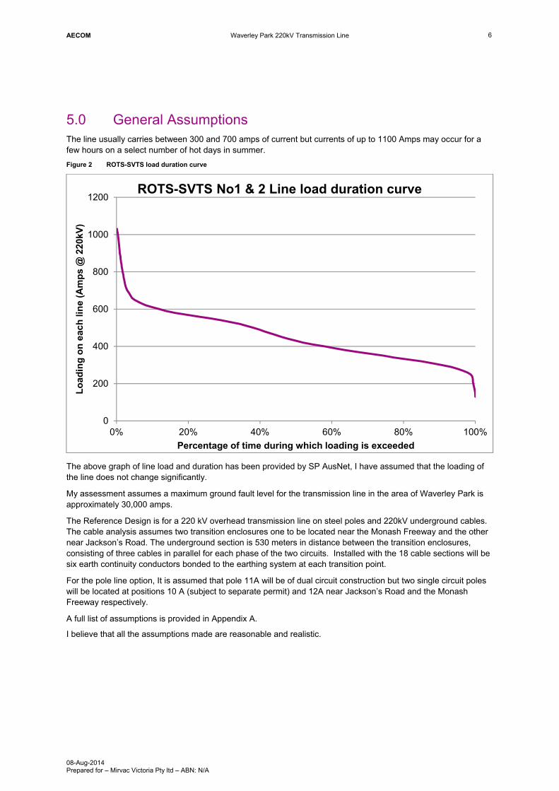
5.0 General Assumptions The line usually carries between 300 and 700 amps of current but currents of up to 1100 Amps may occur for a few hours on a select number of hot days in summer.
Figure 2 ROTS-SVTS load duration curve
The above graph of line load and duration has been provided by SP AusNet, I have assumed that the loading of the line does not change significantly.
My assessment assumes a maximum ground fault level for the transmission line in the area of Waverley Park is approximately 30,000 amps.
The Reference Design is for a 220 kV overhead transmission line on steel poles and 220kV underground cables. The cable analysis assumes two transition enclosures one to be located near the Monash Freeway and the other near Jackson’s Road. The underground section is 530 meters in distance between the transition enclosures, consisting of three cables in parallel for each phase of the two circuits. Installed with the 18 cable sections will be six earth continuity conductors bonded to the earthing system at each transition point.
For the pole line option, It is assumed that pole 11A will be of dual circuit construction but two single circuit poles will be located at positions 10 A (subject to separate permit) and 12A near Jackson’s Road and the Monash Freeway respectively.
A full list of assumptions is provided in Appendix A.
I believe that all the assumptions made are reasonable and realistic.
0
200
400
600
800
1000
1200
0% 20% 40% 60% 80% 100%
Lo
adin
g o
n e
ach
lin
e (A
mp
s @
220
kV)
Percentage of time during which loading is exceeded
ROTS-SVTS No1 & 2 Line load duration curve

AECOM Waverley Park 220kV Transmission Line
08-Aug-2014 Prepared for – Mirvac Victoria Pty ltd – ABN: N/A
7
6.0 Electromagnetic Field Issues
6.1 Guidelines and Standards
Electric and magnetic fields caused by power use are present in relatively small amounts in our general working and living environments. The main sources of these fields are electrical wiring, power line conductors and cables and electrical appliances. In general, higher levels of these fields are recorded near to high voltage transmission lines and terminal station lines.
In Australia, the Australian Radiation Protection and Nuclear Safety Agency (ARPANSA) is the federal government agency responsible for protection the health and safety of people and the environment from the effects of EMF. ARPANSA has advised that the “Interim Guidelines on Limits of Exposure to 50/60 HZ Electric and Magnetic Fields (1989)” issued by the National Health and Medical research Council (NHMRC) are the guidelines currently applicable in Australia.
The Australian Radiation Protection and Nuclear Safety Agency (ARPANSA) has also published a Public Consultation Draft for the Radiation Protection Standard for Exposure Limits for Electric and Magnetic Fields 0 Hz to 3K Hz. This also sets out the guidelines for extremely low frequency fields, both for occupational and general public exposure. It also sets out the scientific basis for the electric and magnetic field exposure limits in Schedule 1 of the Standard. Limits of safe exposure are the same in both documents.
The Interim Guidelines on Limits of Exposure to 50/60 HZ Electric and Magnetic Fields (1989) provides the following recommended exposure level for EMF.
Magnetic Fields
Long Term Exposure Few hours/day
Occupational Exposure 500 μT 1 (per working day) 5000 μT
General Public 100 μT 1000 μT
For open spaces in which the general public might be reasonably expected to spend a substantial part of the day, such as in recreational areas an exposure level of 100 μT applies.
Electric Fields
Long Term Exposure Few hours/day
Occupational Exposure 10 kV/m ( per working day) 30 kV/m
General Public 5 kV/m 10 kV/m
6.2 Electric Fields
Electric fields are created by the electric charges on high voltage equipment. They diminish rapidly with distance and are shielded by common materials such as trees or buildings. Electric fields have not been identified as a public health issue, however, they can potentially cause a number of effects such as audible noise, RF noise and interference and sparks and shocks.
According to the IEEE at the level proscribed at for general exposure, around 7% of adults would experience a spark in a 5KV electric field. The ARPANSA draft standard states “ …since this sensation is similar to that experienced from sparks when touching, for example a door handle after acquiring static from crossing a carpet or getting out of a car seat, this is deemed tolerable.”
1 Magnetic fields are measured in units of Teslas and Gauss and the strength of fields associated with High Voltage power lines is in the micro Tesla (μT) and milligauss range (mG) where 1 μT = 10 mG. Tesla is the unit used in the standards and in the scientific community and has been used in this report.

AECOM Waverley Park 220kV Transmission Line
08-Aug-2014 Prepared for – Mirvac Victoria Pty ltd – ABN: N/A
8
Electric field strengths associated with 220 KV transmission lines typically are in the range of 1 to 3 kV/m under the power lines - well below that of the recommended safe levels - and, at these levels, it is very uncommon for contact shocks to occur. At the edge of the transmission line easement, typically 20 to 30 metres from the power line poles, the electric fields are typically in the range of 0.1 to 1.0 kV/m.
It is also possible for voltages to be induced in long metallic structures that are aligned so that they run parallel to the transmission lines. The induction is small and structures need to be continuous for hundreds of metres for voltage large enough to be felt by humans to be developed. However, it can occur in long metal fences (for example farm fences) and other structures. I am not aware that structures of sufficient length are planned for the Mirvac development and if it were to occur it can be addressed simply by proper earthing practices.
The ground itself provides an effective shield for electric fields associated with underground cables and as a result they effectively do not produce electric fields that would be experienced by the general public.
Because there is no evidence that electric fields at the strengths associated with an overhead transmission line cause harm to humans and because the fields can be readily shielded, electric fields do not pose risks to the general public.
6.3 Magnetic Fields
Magnetic fields arise from the moving electric charges – current. These fields are not shielded by most common materials and easily pass through them. In a similar way to electric fields, magnetic fields also diminish with distance from the source. However, the fields do readily pass through the ground so magnetic fields are associated with underground cables.
The size of the magnetic field will vary during the day as the amount of current varies with the power requirements of the transmission system. Typically current for the lines that cross the Mirvac property will vary from a minimum of about 300 Amps to a maximum of 700 Amps. The magnetic field is proportional to the current carried by the line.
SP AusNet’s publications report that the level of magnetic field created by a transmission line is typically 1– 8 µT under a transmission line and 0.2 – 2.0 µT at the edge of the transmission easement. These levels conform with the modelling I have done for the Mirvac transmission lines.
The level of magnetic fields from above ground and underground transmission lines is similar to that created by some common household appliances such as hair dryers, electric stoves and electric blankets. In fact, magnetic fields produced by appliances which are held close to the body, such as hair dryers, electric shavers and can sometimes exceed those found in transmission line easements.
Table 1 Typical magnetic field values for household appliances
Device Typical Value (µT) Range of Measurements (µT)
Hair Dryer 2.5 1.0 – 7.0
Electric Blanket 2.0 0.5 – 3.0
Electric Stove 0.6 0.2 – 3.0
Computer Screen 0.5 0.2 – 2.0
Toaster 0.3 0.2 – 1.0
Electric Jug 0.3 0.2 – 1.0
Refrigerator 0.2 0.2 – 0.5
Television 0.1 0.02 – 0.2
Electric Fan 0.1 0.02 – 0.2

AECOM Waverley Park 220kV Transmission Line
08-Aug-2014 Prepared for – Mirvac Victoria Pty ltd – ABN: N/A
9
6.4 Magnetic Fields and Health
A number of studies have been conducted investigating the association between magnetic fields and certain medical conditions. Around 20 epidemiological studies have been performed just looking at a possible link between leukaemia and EMFs. Some of these have shown an association between an increase in childhood leukaemia and magnetic fields at low levels but some have found no association. The evidence supporting the association is not conclusive. Animal and in vitro experiments have not provided evidence to support the epidemiological studies nor have they established a biophysical induction mechanism for the development of cancer. A causal relationship has not been established.
Electric Utilities have adopted a policy of “prudent avoidance” to avoid and manage perceived health risks. This means taking simple, easily achievable, low cost measures to reduce exposure to EMF, even in the absence of demonstrable risk. Mirvac has adopted this principal by providing an additional buffer outside the easement as shown in their Waverley Park Propose Power Line Plan drawing No TL TP1000a revision D.
6.5 Reducing Magnetic Fields
There are a number of ways to reduce EMF effects: Firstly, as the magnitude of the EMF is inversely proportional to the distance from the current carrying elements, one can increase the distance of the public from the conductors. Hence by increasing the width of an easement, increasing the height of a transmission line or increasing the distance to the boundary of the terminal station will reduce the magnetic field strength magnitude. Higher transmission poles will produce a lower EMF, so there is a potential trade-off between the height of a transmission pole and its effect on visual amenity and the reduction in EMF. There are practical limits to the physical height of poles and size of the easements and substation sites so this solution, whilst generally practical, does not suit every situation.
Cancellation of magnetic fields between different conductors is possible because of the phase relationship between the conductors. This means that the spatial arrangement of conductors can be used to reduce the EMF. Cancellation offers the best opportunity to cost effectively reduces EMF and is commonly applied as part of a utilities prudent avoidance practice.
More compact structures have lower EMF as better cancellation of the fields occurs if the conductors are close together but there are engineering limits to how close conductors can be place to each other. Generally speaking, construction is more compact at lower voltages so less EMF will be produced for a 66kV transmission line than a 220kV transmission line for a given current.
EMF shielding is possible using materials of high magnetic permeability. However, this solution is expensive and usually only used to solve specific local problems.
Other solutions, such as current cancellation loops may offer alternative, but less proven options for addressing magnetic field problems.
The various solutions are applied during detailed design. Generally speaking physical separation will provide appropriate EMF levels and this particularly applies to transmission lines through rural areas where the lines are well away from areas frequented by people. Special design can be applied for local problems.

AECOM Waverley Park 220kV Transmission Line
08-Aug-2014 Prepared for – Mirvac Victoria Pty ltd – ABN: N/A
10
6.6 Options and EMF
6.6.1 Overhead Transmission Lines
The magnetic field strengths across the transmission line easement have been modelled.
For both overhead lines and underground cables, the magnetic field strengths are highest at the closest points to the current carrying conductor. For overhead lines, the field strengths vary with the height of the conductor and are largest at the mid span point between the poles where the conductors are closest to the ground but much smaller at the poles.
The field strengths will also vary depending on the amount of current flowing through the conductors. This is demonstrated in the following graphs.
Figure 3 Magnetic field strength across easement for overhead option with various levels of current
The magnetic field strength varies considerably between the poles and the midpoint span – at 700 Amps line current from about 10 µT at the mid span to less than 1µT at the pole 11A. This compares with the level allowed by the Guidelines of 100ut.
Typical field strengths for mid-span and pole locations are shown in figures 3 and 4 respectively, plotted on the same scale.

AECOM Waverley Park 220kV Transmission Line
08-Aug-2014 Prepared for – Mirvac Victoria Pty ltd – ABN: N/A
11
Figure 4 Magnetic field strength at structure 11A
6.6.2 Underground Transmission Cables
Magnetic fields are not shielded by being buried and fields will remain and be at their maximum especially directly above the cables and within the cable easement. As magnetic fields are caused by the current flowing in the cable, EMF produced will be determined by the current and not by the voltage of the cable. Underground cables are generally laid quite close to one another so good cancellation between the fields created by each cable phase is achieved which reduces EMF
A trefoil arrangement, where three cables are laid in a triangular group will have a lower EMF than those laid flat in a row. This is the arrangement proposed for the Mirvac cable.
Figure 5 Trefoil Cable Arrangement
AECOM Waverley Park 220kV Transmission Line
08-Aug-2014 Prepared for – Mirvac Victoria Pty ltd – ABN: N/A
12
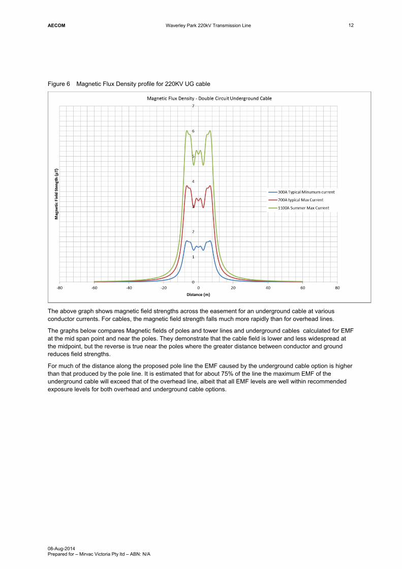
Figure 6 Magnetic Flux Density profile for 220KV UG cable
The above graph shows magnetic field strengths across the easement for an underground cable at various conductor currents. For cables, the magnetic field strength falls much more rapidly than for overhead lines.
The graphs below compares Magnetic fields of poles and tower lines and underground cables calculated for EMF at the mid span point and near the poles. They demonstrate that the cable field is lower and less widespread at the midpoint, but the reverse is true near the poles where the greater distance between conductor and ground reduces field strengths.
For much of the distance along the proposed pole line the EMF caused by the underground cable option is higher than that produced by the pole line. It is estimated that for about 75% of the line the maximum EMF of the underground cable will exceed that of the overhead line, albeit that all EMF levels are well within recommended exposure levels for both overhead and underground cable options.

AECOM Waverley Park 220kV Transmission Line
08-Aug-2014 Prepared for – Mirvac Victoria Pty ltd – ABN: N/A
13
Figure 7 Comparison of EMF between overhead line and underground cable at Mid Span
Figure 8 Comparison of EMF between overhead line and underground cable at pole

AECOM Waverley Park 220kV Transmission Line
08-Aug-2014 Prepared for – Mirvac Victoria Pty ltd – ABN: N/A
14
6.6.3 Transition Enclosures
The underground cable requires transition enclosures at each end of the cable. The electric and magnetic fields within the underground to overhead transition enclosure are a function of the geometry of the transition equipment, the voltages at which the equipment is energised and the current that passes through it.
The transition enclosures are a working environment and they are designed so that the occupational guidelines of the Radiation Protection Standard are met. Equipment within the transition enclosures is located far enough from the enclosure fence so that field exposure to the general public is well within recommended levels. .
As the proposed design of the two enclosure stations for this project have been previously completed, it is possible to model the compound for EMF. This modelling has shown that the public exposure to fields will be similar to at those experienced at the edge of the transmission line easement.
6.6.4 Precautions for the General Public
Where public exposure exceeds the reference exposure levels, the ARPANSA standard recommends that the precautions taken to protect the public might include:
- Determination of the boundaries of the areas where general public exposure limits may be exceeded.
- Restriction of public access to those areas where general public exposure limits may be exceeded.
- Appropriate provision of warning signs or notices
- Taking measures, as appropriate to the risk involved to limit or eliminate the fields.
However, as the likely exposure levels are significantly less than the reference levels, these measures are not required.
A prudent avoidance philosophy has been implemented during the preliminary design of both the cables and overhead lines. In particular, Mirvac has chosen to allow an additional buffer between the transmission line and cable easements and the nearest houses. The pole line buffer proposed by Mirvac is shown on Waverley Park Proposed Power Line Plan drawing number TL-TP1100a rev D. Prudent avoidance reflects the Electricity Industry’s desire to err on the side of safety even in the absence of demonstrable risk.
6.7 EMF Conclusions
For both the underground cable option and the overhead line options, the line routes will pass through public space. For both options the electric and magnetic field strengths experienced by the public are well within those recommended by the Standard and Guidelines.
For electric fields, the underground cable option will not produce electric fields as the ground provides an effective shield.
For the overhead line option, the field strengths are at a maximum within the transmission easement and will have a level of approximately 1-3kV/m, about half the recommended level. At the edge of the transmission line easement, typically 20 to 30 metres from the power line poles, the electric fields will be even smaller and are typically in the range of 0.1 to1.0 kV/m. In my opinion, these electric fields will not pose a risk to the public.
For magnetic fields, the standards recommend a safe level of exposure of 100µT for constant exposure, 24 hours per day and 100µT is also the recommended exposure level for public areas such as parks and recreational areas. The magnetic field strength will vary from day to day and throughout the day as the power flow in the transmission line increase.
For overhead lines, the maximum values will occur at the lowest conductor point, mid span between the poles. Typically these values will be between 4 and 10 µT. At the poles, the conductors are higher above the ground and the fields experienced by the public will be much less, typically in the range 0.4 to 1.6 µT.
For the underground cable option, the ground will not shield the magnetic field. The cable is buried at a constant depth and magnetic field will be constant across the cable length except varying with the power flow. Typically the magnetic field strength from cables will be in the range 1.6 – 3.8 µT.
All the magnetic fields are at least an order of magnitude lower than the safe levels provided by the standard. In my opinion, magnetic fields associated with the transmission line do not pose a risk to the public.

AECOM Waverley Park 220kV Transmission Line
08-Aug-2014 Prepared for – Mirvac Victoria Pty ltd – ABN: N/A
15
7.0 Earth Potential Rise During a fault on a transmission line, current may flow into the local earthing system on its way back to the source. These current can cause the potential (or voltage) rise on the local earthing systems and earthing systems must be properly designed to deal with the hazards.
It is impossible to prevent the presence of hazardous voltages at all times. However with careful earthing design acceptable solutions can be found that reduce risks to a negligible amount.
Overhead lines have earth wires that run above the power carrying conductors. The purpose of the earth wire is both to provide shielding from lightning and to form part of an extended earthing system along the pole line. These earth wires are connected through the pole structures to a local earthing point. Current will flow into local earthing points for earth faults that occur on the line and for earth faults that occur elsewhere, but whose current flow through the line earth wires. This current will flow through the earth wires to the local earthing point at the base of poles.
For the proposed underground cable options, transition enclosures will be required at the end of the cables where the cables are attached to the transmission line. An extensive earth grid is provided at the transition enclosure to provide safe operating conditions for SP AusNet staff. The earth grid at each transition enclosure is connected to the other by earthing cables running underground with the power cables. The transition enclosure earths will also be connected to the overhead line earthing conductors on the poles.
7.1 Standards for Earth Potential Rise
There are a number of standards that address the requirement for safe earthing. Some of the standards are:-
- AS/NZS 60479 Effects of current on human beings and livestock
- ENA EG0 Power system earthing guide, Part 1: Management principles
- ENA EG1 Substation earthing guide
- IEEE Std80 IEEE guide for safety in AC substation grounding
- IEEE Std81 IEEE Guide for measuring earth resistivity, ground impedance, and earth surface potentials of a grounding system
- AS 2067 Substations and high voltage installations exceeding 1kV a.c.
- AS/NZS 3000 Electrical installations (known as the Australian/New Zealand Wiring Rules)
- AS/NZS 3835 Earth potential rise – Protection of telecommunications network users, personnel and plant
- AS/NZS 7000 Overhead line design detailed procedures.
The documents all have the same basis but the recommended allowable EPR does differ between standards used for terminal stations and substations on the one hand and transmission lines on the other. The earth grids of terminal and substations are generally designed in accordance with IEEE Std 80 guidelines which are generally more onerous than the transmission line standard AN/NZS 7000. This is because the substations inherently are exposed to more fault events than lines. The potential of their station earth grids will rise for each fault on all transmission lines connected to it whereas a transmission line earthing caters for fewer faults, only those associated with the line itself.
SP AusNet has indicated that, for the underground cable option, it would like the transition enclosure’s earthing system to be designed to the IEEE Std 80. In addition SP AusNet’s rule of thumb design criteria is to keep the 1000V EPR contour within the boundary of the terminal station ( in this case transition enclosure) fence. This meets the requirements for earth potential rise in AS/NZS 3835 table 2.
Another Standard, ENA EG-0, was released in August 2010 and it introduces a direct, probabilistic development of earthing system safety criteria. The criteria are derived by assessing the probability of the coincidence (of a subject being placed in a reasonably foreseeable contact scenario during a fault) and the probability of the fibrillation (the voltage hazard leading to a ventricular fibrillation). By considering probability the standard seeks to provide a better engineering solution for very rare events that may pose an earthing hazard.

AECOM Waverley Park 220kV Transmission Line
08-Aug-2014 Prepared for – Mirvac Victoria Pty ltd – ABN: N/A
16
The probability of a fatality is compared to the likelihood of occurrence, with a risk below 1 x 10⁻⁶ being referred to as negligible risk. A risk determined to be in the negligible range does not negate the need to undertake reasonable practical risk reduction measures.
Standard AS/NZS 7000 for overhead line design has also adopted a risk based approach based on ENA EG0.
7.2 Earth Potential Rise Guidelines
7.2.1 Standard AS/NZS 3851
Standard AS/NZS 3851 applies to the telecommunication network users and defines EPR hazard limits of 1500V, 1000V and 430V as per the table below:
Table 2 AS/NZS 3851 EPR hazard limits
Limit category
Category A Category B Category C
Reliability High High Not High
Fault Duration ≤ 0.35 sec ≤ 0.5 sec Any
EPR Hazard Voltage Limit 1500 V or 1000V 1000 V 430 V
The Rowville to Springvale transmission line can be considered as category A. – A high reliability circuit with a fault duration ≤ 0.35 sec. For category A circuits, the HV line structures > 200KV, the 1500V limit applies except where telecommunication equipment cannot with stand 1500V, when 1000V should be used.
7.2.2 Standard AS/NZS 7000
Standard AS/NZS 7000 applies to overhead line design. It recommends the following EPR limits. This standard provides curves of acceptable voltage touch criteria plotted against fault clearance times. Data points in the following table are used to generate that curve.
Table 3 AS/NZS 7000 EPR hazard limits
Curve Voltage (V) Clearance Time (s)
Transmission Urban < 1S TU 8000 0.2
Transmission Urban > 1 TU 800 1
Distribution Urban DU 800 1
Transmission Distribution Backyard TDB 181 1
Transmission Distribution MEN TDMEN 121 1
Under this standard the Rowville to Springvale transmission line would be considered category TU. The recommended EPR voltage is 8000V.
The standard also indicates the basis of each curve and scenarios used in developing the curves. These are shown in the table below.

AECOM Waverley Park 220kV Transmission Line
08-Aug-2014 Prepared for – Mirvac Victoria Pty ltd – ABN: N/A
17
Table 4 AS/NZS 7000 basis of EPR hazard limits
Curve Fault Frequency/Y
Contact scenario Footwear
Transmission Urban TU 0.1 Urban – 100 contacts per year for 4 s for clearing times to 1sec >66kV
Standard
135 contacts per year for 4 s clearing times above 1 s (<66kV)
Distribution Urban DU 0.1 135 contacts/y for 4 s Standard
Transmission Distribution backyard
TDB 0.1 Back yard – 416 contacts per year for 4 s
Standard
Transmission Distribution MEN
TDMEN 0.1 Men – 2000 contacts/year for 4 sec
Standard
Remote N/A 0.1 Less than 60 off (4 s) contacts for 1 S fault duration, or less than 75 off (4 s) contacts of 0.2 s fault duration
Standard
7.2.3 IEEE Std 80
The IEEE std 80 defines the method of calculation of allowable step and touch voltage in terms of clearing time, body weight, the resistivity of both earth and surface layer and surface layer thickness.
The table below was produced by Safearth Consulting for transition enclosure associated with undergrounding the line in accordance with IEEE std 80. It provides the allowable voltages for a 50kg (child) and a 70KG (adult) person. Soil resistivity level of 20 Ωm and 2000 Ωm represent typical resistivities of soil and crushed rock surface respectively with crushed rock typically being used in substations.
Table 5 Allowable voltages for persons (Safearth Report)
Fault Scenario
Clearing time
Body weight Local Soil Resistivity (Ωm)
Allowable Limits (V)
Touch Voltage
Step Voltage Hand to Hand
220KV Earth Fault
0.1 50kg 20 378 V 411 V 367 V
2000 944 V 2676 V
70kg 20 511 V 556 V 405 V
2000 1280 V 3622 V
The three examples above provide an example of the varying EPR requirements of the various standards. Standard AS/NZS 3851 address the needs of the communications industry. Standard AS/NZS 7000 is for overhead lines and considers the likelihood of a hazard in determining the practical voltage level. IEEE Std 80 calculates the EPR that will cause a hazard.
For overhead pole line design, SP AusNet will typically use the Standard AS/NZS 7000 and earthing at the pole will be sufficient to provide an EPR of < 8000 V. At this EPR a hazard may exist but it would be very rare and the likelihood of serious harm from a fault is negligible.
SP AusNet’s approach is to use the IEEE Std 80 for calculations within the station and to then check that the 1000V contour does not go outside the station boundary, effectively meeting Standard AS/NZS 3851 outside the station.
I believe these approaches are reasonable and will produce a safe earthing design in accordance with the Standards and with negligible risk to the public.

AECOM Waverley Park 220kV Transmission Line
08-Aug-2014 Prepared for – Mirvac Victoria Pty ltd – ABN: N/A
18
7.3 Earth Potential Rise – Overhead Lines
Pole structures are connected to an earth grid at their base. When earth current flows through the pole to the earth grid, an earth potential will be caused by the current flowing into the ground. It is expected that these transmission lines would have been designed to the criteria in AS/NZS 7000 with an allowable touch voltage of not more than 8000 V. The standard recognises that high voltages only occur in very rare circumstances and that the danger occurs only in the immediate vicinity of the pole. Dangerous voltages generally do not extend beyond the transmission line easements and circumstances that would expose a person to these voltages very unlikely. If poles are built, they too would be designed to comply with the standard.
Typical fault rates for overhead transmission lines occur at the rate of less than one fault per 100km of line length per year. Hazardous voltage on the pole line caused by earth potential rise will only occur for local faults – those within three spans or about 750m of the pole. These faults will be isolated and cleared with 0.1 seconds. The exposure to a hazardous event is in the order of 0.1 seconds every 100 years.
In my opinion, the risk associated with hazardous EPR for power lines is negligible.
7.4 Earth Potential Rise – Underground Cables
Earth potential rise hazards in the underground cable options occur at the transition enclosures. A larger earth grid is required to control the EPR so that it is safe to work within the transition enclosure. The effect of the larger earth grid is to extend dangerous EPR beyond the enclosure boundary, and perhaps into the surrounding houses where it may cause a hazard.
In addition, the larger earth grid means that faults that occur in a wider area will cause an earth potential rise large enough to cause a hazard at the transition enclosures. Faults that occur anywhere along the transmission line between Rowville and Springvale as well as faults that occur on the transmission lines between Springvale and Heatherton Terminal station will cause EPR at the enclosures.
In my opinion, the combined effects of the EPR occurrence being more likely and the number of people being exposed to EPR being greater means that the risk of an EPR hazard for the transition enclosures will not be negligible.
7.5 Earthing System Design
SP AusNet commissioned an earthing design for the two transition enclosures from Safearth Consulting in 2010 (see Appendix B). The report provided an analysis of the proposed earthing design for the two transition enclosures. It considered the earth potential rise for both through faults (beyond the Waverley Park section of line which cause EPR) and faults within the Mirvac Waverley Park section of the line.
Their report states that the proposed installation met the requirements for AN/SZS 7000 for transmission lines but “that the touch voltages in the nearby MEN area may be present during a fault that does not satisfy the criteria of ENA EG-1”.
The report also performed a probabilistic assessment of the installation in accordance with ENA EG-0 and found that for a through fault, the risk of fatality exceeded 1.0 x 10⁻⁶ at both the Jacksons Road and Monash Freeway transition points and recommended that further mitigation should be taken to reduce the risk.
The mitigation measures proposed by Safearth Consulting were to improve the earthing resistance around four adjacent towers. The measures are at a reasonable cost and have the effect of reducing the EPR by a further factor of 10. Once this mitigation is carried out, Safearth Consulting has estimated that the risk will be reduced and fall into the negligible risk category. In my opinion, the mitigation measures recommended by Safearth Consulting will meet the ENA EG0 guidelines in a probabilistic sense but the danger remains in an absolute sense. Even with mitigation measures applied at the transition enclosures, the overhead line option provides an EPR safety outcome that is an order of magnitude less likely to occur that for the underground cable option and for that reason is safer.

AECOM Waverley Park 220kV Transmission Line
08-Aug-2014 Prepared for – Mirvac Victoria Pty ltd – ABN: N/A
19
7.6 EPR Conclusion
Earth potential rise hazards are associated with both overhead line and underground cable options. For the overhead line options, the hazards will occur in vicinity of the poles and will occur for earth faults that occur within a few spans of the pole.
For the underground cable option, the hazards are associated with EPR emanating from the transition enclosures. Hazards will occur more often and will affect a wider area, with the hazards area extending to residential houses near the enclosures. For the transition enclosures, it is possible to meet the requirements of the ENA EG-0 guidelines with mitigation measures but they will continue to pose a higher risk. All other things being equal, I would recommend the pole line option over that of the underground cable option on the basis of safety risk.

AECOM Waverley Park 220kV Transmission Line
08-Aug-2014 Prepared for – Mirvac Victoria Pty ltd – ABN: N/A
20
8.0 Conclusion For both overhead pole line and underground cable construction options for Mirvac’s Waverley Park development there are two issues where members of public may have concern about the health and safety risks. These are Electromagnetic Fields (EMF) and Earth Potential Rise (EPR).
For both EMF and EPR there are Australian Standards and Guidelines for safe levels of exposure and proper design. For both overhead and underground line options, the requirements of these standards and guidelines can be met.
Power lines produce both electric and magnetic fields but only magnetic fields have been associated with health risks. Recommended safe field strength for public exposure to magnetic fields is 100 μT. Across the Mirvac development site, maximum field strengths are typically in the range of 3 – 7 μT directly under overhead lines and 4 μT for underground cables - both well within safe limits.
The issue posed for EPR is that it is possible for dangerous voltages to arise around the poles and transition enclosure during earth fault conditions. The levels of EPR recommended by the standards and guidelines vary depending on the location of the fault and higher levels are permitted for lines than for terminal stations. The underground cable option requires the establishment of transition enclosures at the end of the cables, where the overhead line is connected to the underground cable. Without mitigation measures the EPR at these transition enclosures meet the criteria set out in the standards for overhead lines, but not those for terminal stations.
In recent years, some Australian Standards and guidelines for earthing have been changed to incorporate probabilistic safety criteria. They provide a methodology for assessing risk and if the likelihood of a fatality is less than 1 x 10⁻⁶ the risk is referred to as negligible and regarded as acceptable.
Engineering solutions exist that will mitigate the risk associated with both underground and pole options to negligible values at moderate incremental cost. However the risk associated with a pole line will remain an order of magnitude less likely to occur than the underground option because
- hazardous voltages do not occur outside the power line easement with pole line whereas with the underground cable solution they are likely to extend into residential areas and hence expose more people to risk.
- hazardous voltage will be produced at the transition enclosures by faults on the wider transmission network and will therefore be more likely to occur.
For this reason the pole line option, is in my opinion, inherently safer than the underground cable option.
In producing this statement, for the EMF assessment, I relied on my own calculations and have performed modelling of line and cable EMF. However, for the EPR calculations, I have relied on the report produced by Safearth Consulting in 2010.
I have made all the inquiries that I believe are desirable and appropriate and that no matters of significance which I regard as relevant have to my knowledge been withheld from the Tribunal.
Signed
Date: 08/08/2014

AECOM Waverley Park 220kV Transmission Line
08-Aug-2014 Prepared for – Mirvac Victoria Pty ltd – ABN: N/A
Appendix A
Assumptions

AECOM Waverley Park 220kV Transmission Line
08-Aug-2014 Prepared for – Mirvac Victoria Pty ltd – ABN: N/A
Appendix A Assumptions Required Power
It is assumed that the Rowville – Springvale 220kV transmission line will transmit on average 300 – 700A of power supply between terminal station ends, but that its ultimate load capacity will be 1100A (which equates to approx. 420MVA assuming a 0.9 power factor). This assumption is based on real time currents receive from SP AusNet for the transmission line load over the last 365 days.
Based on actual ratings received from SP AusNet, maximum current will be carried along the line for short periods of a few hours per day, amounting to a total of 24hrs per calendar year. The durations of “maximum load” usually occur for a few hours on the hottest days of the year, when daytime temperatures are at their peak.
For modelling purposes, we have assumed that current, up to a line rating of 1100Amps will be carried.
Power (assumed 0.9 power factor)
Current in each circuit Maximum current (one circuit out of service)
115 MVA (average low) 300 Amps 600 Amps
265 MVA (average high) 700 Amps 1100 Amps
380 MVA (maximum demand) 1100 Amps Not Applicable
1) 220kV Underground Transmission Line Option
Underground cables are capable of carrying approx. 900 Amps. In a 220KV cable option, three cables per phase would are required.
2) 220kV Overhead Transmission Line Option
The proposed option is to maintain an overhead line across the Mirvac development using steel poles in place of existing tower structures. The overhead solution would include two new spans of conductor along the diversion and maintain the same current rating as the existing line.
Conductor Height and Transmission Line Dimensions
EMF is affected both by the spatial relationship of the conductors to each other and the distance from the conductors to the ground. The following assumptions have been assumed in our calculations.
Line Description
Minimum Conductor Height Above/Below Ground
Vertical distance between conductors
Cross Arm Width (Double Circuit)
Easement Width
220KV Lattice 10m 4.9m 9.4m 40m
220KV Pole 9.5m 5.6m 9.5m 40m
220kV U/G cable 1.2m Trefoil formation 2.8m between cable groups
17m
3) Other Assumptions
- Ground currents have been ignored. This is a valid assumption as they will have negligible effects on the EMF for distances less that 100m from the centre line.
- Earth wire currents and their effect on EMF have not been considered for the overhead lines. These may increase EMF.
- The locations of terminations and transpositions along the line will also affect and vary EMF.
- Zero sequence currents will also affect EMF. They should not be present under normal conditions if lines have been well designed and load is balanced.
- The above issues need to be addressed in the detailed design phase so that a low EMF result is achieved.

AECOM Waverley Park 220kV Transmission Line
08-Aug-2014 Prepared for – Mirvac Victoria Pty ltd – ABN: N/A
Appendix B
Safearth Report