WaveMapper Manual 1.0
50
PPG WaveMapper User Manual
-
Upload
sam-miller -
Category
Documents
-
view
229 -
download
0
Transcript of WaveMapper Manual 1.0

8/13/2019 WaveMapper Manual 1.0
http://slidepdf.com/reader/full/wavemapper-manual-10 1/50
PPG WaveMapper
User Manual
8/13/2019 WaveMapper Manual 1.0
http://slidepdf.com/reader/full/wavemapper-manual-10 2/50
Concept & Programming:Wolfgang Palm
GUI Design:
Cornel Hecht
Sound Design:
Boele Gerkes, Jay de Miceli, Peter Gorges,
nachtsmeer
Marketing, Press & Artist Relations:Russ Hughes
Manual:
Boele Gerkes
Credits:
David Israel, Drew Pearson, Geert Bevin,
Bjørn Eilertson, Kenneth Abildgaard,
Nahuel Mijalovsky, Steve Harrington,
Jesse Juup, Russ Hughes, Sean Cooper
© 2013 PPG, Wolfgang Palm, Hamburg,
Germany
PPG on Facebook:
http://www.facebook/ppgwavegenerator
Wolfgang Palm website:
http://www.wolfgangpalm.com
8/13/2019 WaveMapper Manual 1.0
http://slidepdf.com/reader/full/wavemapper-manual-10 3/50
Contents
Introduction 5
PPG WaveMapper 5
Mapping 5
New analysis/synthesis system 5
User interface 6
Before you read on 7
Let’s play 8
Root and preset programs 9
Oscillator resources 9
MAPPING module 10
PARAMETERS module 13
OSCILLATORS sub module 13
PITCH section 14
ENVELOPE/WAVE section 15
Overall envelope usage 18
Wave envelopes: paths 19
WAVE section 21
NOISE+FILTER sub module 23
FILTER INPUT MIX section 23
NOISE COLOR section 24
ENVELOPE and RINGMODULATOR
section 25
FILTER section 25
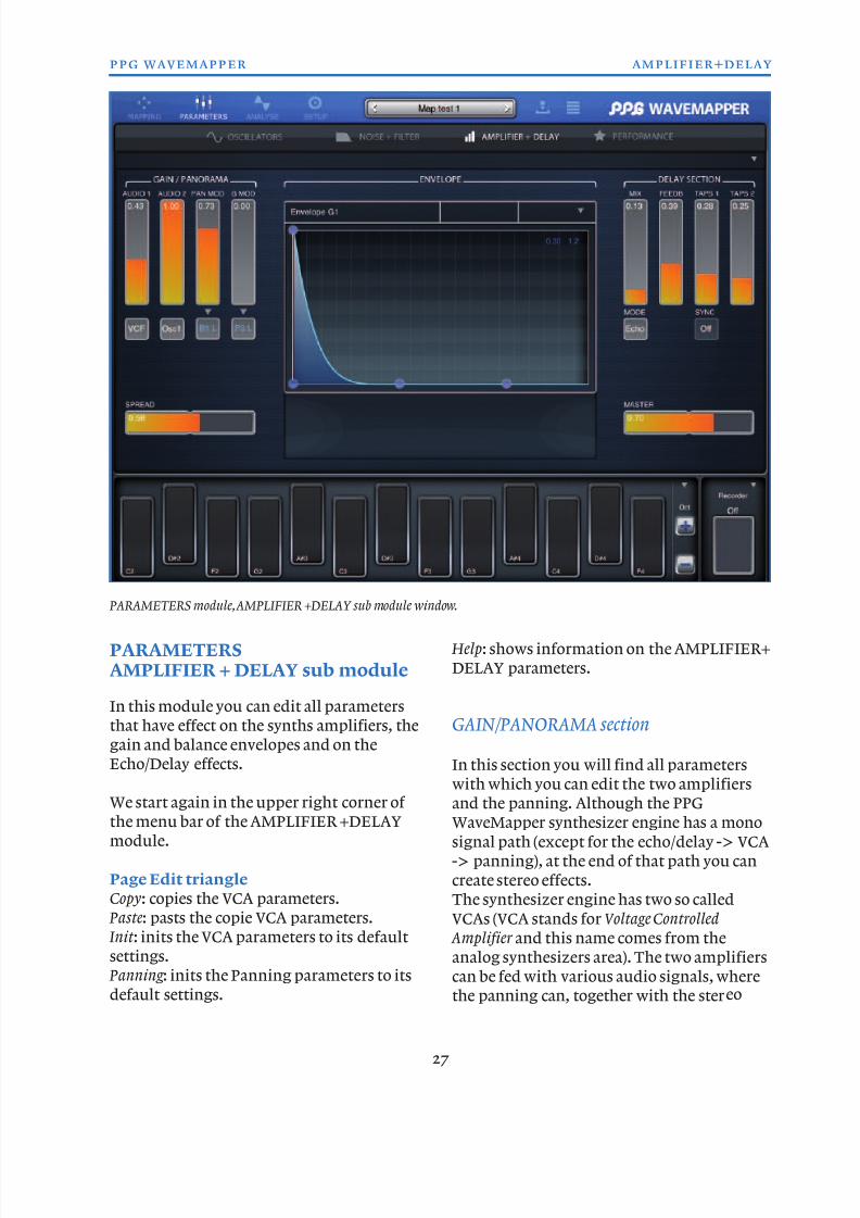
AMPLIFIER+DELAY sub module 27
GAIN/PANORAMA section 27
ENVELOPE section 28
DELAY section 29
PEFORMANCE sub module 30
ARPTOR section 30
KEYBOARD section 32
ENVELOPE section 32
LFO section 33
SOUND CATEGORY section 34
ANALYSE page 36
SETUP module 39
SYSTEM section 39
SYNTHESIZER section 40
MIDI IN/OUT section 41
PROGRAM EDIT 43
PROGRAM BROWSER module 43PROGRAM MANAGER section 43
BANK MANAGER section 44
PROGRAM BROWSER section 44
KEYBOARD 46
RECORDER 48
VARIOUS 48
Interaction between PPG WaveMapper andPPG WaveGenerator 48
AudioBus 48
MIDI CCs 48
Full MIDI CC list 49
8/13/2019 WaveMapper Manual 1.0
http://slidepdf.com/reader/full/wavemapper-manual-10 4/50
8/13/2019 WaveMapper Manual 1.0
http://slidepdf.com/reader/full/wavemapper-manual-10 5/50
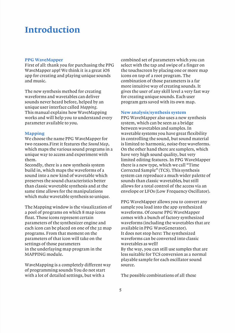
Introduction
PPG WaveMapper
First of all: thank you for purchasing the PPG
WaveMapper app! We think it is a great iOS
app for creating and playing unique sounds
and music.
The new synthesis method for creating
waveforms and wavetables can deliver
sounds never heard before, helped by an
unique user interface called Mapping .This manual explains how WaveMapping
works and will help you to understand every
parameter available to you.
Mapping
We choose the name PPG WaveMapper for
two reasons.First it features the Sound Map,
which maps the various sound programs in a
unique way to access and experiment with
them.
Secondly, there is a new synthesis system
build in, which maps the waveforms of a
sound into a new kind of wavetable which
preserves the sound characteristics better
than classic wavetable synthesis and at the
same time allows for the manipulations
which make wavetable synthesis so unique.
The Mapping window is the visualization of
a pool of programs on which 8 map icons
float. Those icons represent certainparameters of the synthesizer engine and
each icon can be placed on one of the 32 map
programs. From that moment on the
parameters of that icon will take on the
settings of those parameters
in the underlaying map program in the
MAPPING module.
WaveMapping is a completely different way
of programming sounds You do not startwith a lot of detailed settings, but with a
combined set of parameters which you can
select with the tap and swipe of a finger on
the touchscreen by placing one or more map
icons on top of a root program. The
combination of those parameters is a far
more intuitive way of creating sounds. It
gives the user of any skill level a very fast way
for creating unique sounds. Each user
program gets saved with its own map.
New analysis/synthesis system
PPG WaveMapper also uses a new synthesis
system, which can be seen as a bridge
between wavetables and samples. In
wavetable systems you have great flexibility
in controlling the sound, but sound material
is limited to harmonic, noise-free waveforms.
On the other hand there are samplers, which
have very high sound quality, but very
limited editing features. In PPG WaveMapper
there is a new type, which we call “Time
Corrected Sample” (TCS). This synthesis
system can reproduce a much wider palette of
sounds than classic wavetables, but still
allows for a total control of the access via an
envelope or LFOs (Low Frequency Oscillator).
PPG WaveMapper allows you to convert any
sample you load into the app synthesized
waveforms. Of course PPG WaveMapper
comes with a bunch of factory synthesizedwaveforms (including the wavetables that are
available in PPG WaveGenerator).
It does not stop here: The synthesized
waveforms can be converted into classic
wavetables as well!
By the way, you can still use samples that are
less suitable for TCS conversion as a normal
playable sample for each oscillator sound
source.
The possible combinations of all these
5
8/13/2019 WaveMapper Manual 1.0
http://slidepdf.com/reader/full/wavemapper-manual-10 6/50
different waveforms make PPG WaveMapper
capable of achieving limitless sounds.
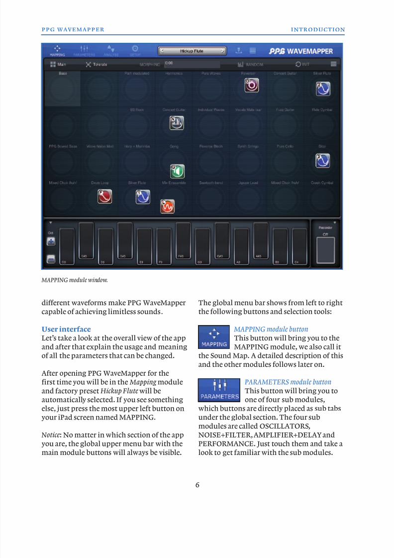
User interface
Let’s take a look at the overall view of the app
and after that explain the usage and meaning
of all the parameters that can be changed.
After opening PPG WaveMapper for the
first time you will be in the Mapping module
and factory preset Hickup Flute will be
automatically selected. If you see something
else, just press the most upper left button on
your iPad screen named MAPPING.
Notice: No matter in which section of the app
you are, the global upper menu bar with the
main module buttons will always be visible.
The global menu bar shows from left to right
the following buttons and selection tools:
MAPPING module button
This button will bring you to the
MAPPING module, we also call it
the Sound Map. A detailed description of this
and the other modules follows later on.
PARAMETERS module button
This button will bring you to
one of four sub modules,
which buttons are directly placed as sub tabs
under the global section. The four sub
modules are called OSCILLATORS,
NOISE+FILTER, AMPLIFIER+DELAY and
PERFORMANCE. Just touch them and take a
look to get familiar with the sub modules.
6
ppg wavemapper introduction
MAPPING module window.
8/13/2019 WaveMapper Manual 1.0
http://slidepdf.com/reader/full/wavemapper-manual-10 7/50
ANALYSE page button
This button will bring up the
ANALYSIS module window,
where you can import samples, convert them
into synthesized waveforms, convert those
waveforms into waves and wavetables etc.
SETUP module button
This brings you to a module
window with global user settings
like audio quality, MIDI settings etc.
Left and right PROGRAM SELECTION buttons These buttons will select the program before
and after the actual selected program, which
name is visible in between the program
selection buttons.
Notice: you can always change the name of a
program by tapping in the name field. You
have to save the program to save the new
name.
PROGRAM TOOLS symbol
Tapping this button will bring up a
popup menu with program save,
init and copy parameters as well as
a randomize parameter and a help menu
selection with a short description of these
program editing parameters.
PROGRAM BROWSER module button
Touching this button will bring you
to the browser module window withthree sections where you can select,
order and edit programs, edit program
banks, edit program categories etc.
Touching the PPG WaveMapper logo will
show the apps version number and some
other related info.
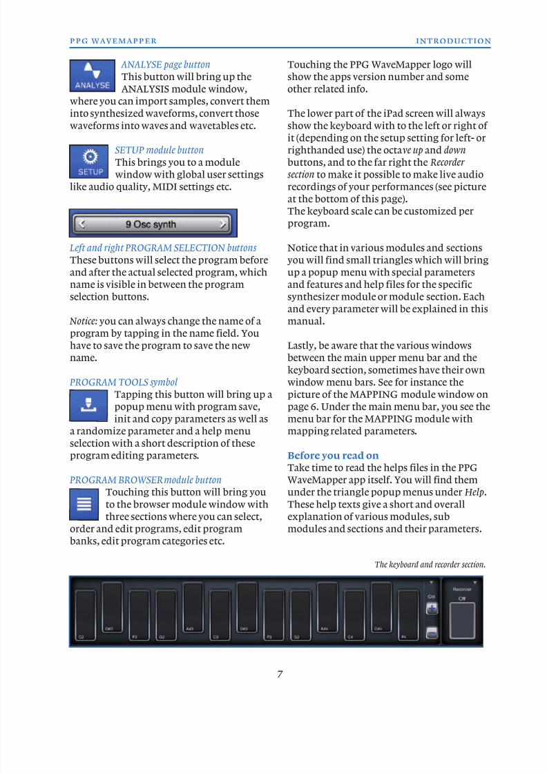
The lower part of the iPad screen will always
show the keyboard with to the left or right of it (depending on the setup setting for left- or
righthanded use) the octave up and down
buttons, and to the far right the Recorder
section to make it possible to make live audio
recordings of your performances (see picture
at the bottom of this page).
The keyboard scale can be customized per
program.
Notice that in various modules and sectionsyou will find small triangles which will bring
up a popup menu with special parameters
and features and help files for the specific
synthesizer module or module section. Each
and every parameter will be explained in this
manual.
Lastly, be aware that the various windows
between the main upper menu bar and the
keyboard section, sometimes have their own
window menu bars. See for instance the
picture of the MAPPING module window on
page 6. Under the main menu bar, you see the
menu bar for the MAPPING module with
mapping related parameters.
Before you read on
Take time to read the helps files in the PPG
WaveMapper app itself. You will find them
under the triangle popup menus under Help.
These help texts give a short and overallexplanation of various modules, sub
modules and sections and their parameters.
7
ppg wavemapper introduction
The keyboard and recorder section.
8/13/2019 WaveMapper Manual 1.0
http://slidepdf.com/reader/full/wavemapper-manual-10 8/50
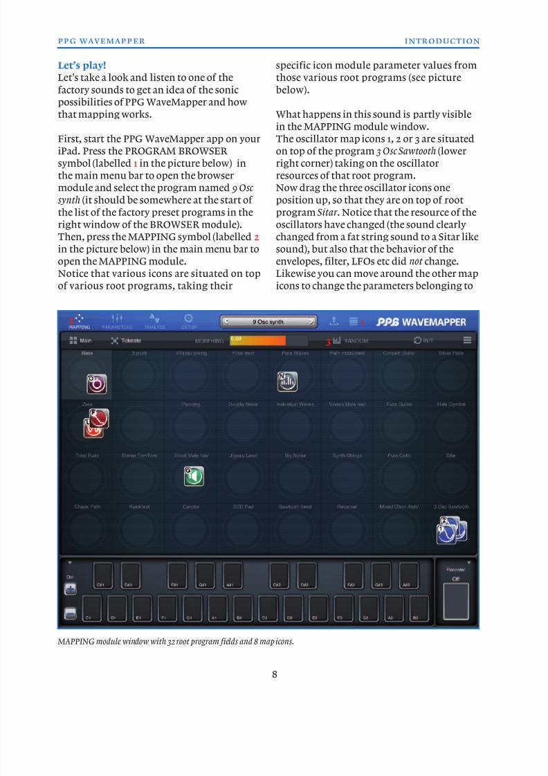
Let’s play!
Let’s take a look and listen to one of the
factory sounds to get an idea of the sonic
possibilities of PPG WaveMapper and how
that mapping works.
First, start the PPG WaveMapper app on your
iPad. Press the PROGRAM BROWSER
symbol (labelled 1 in the picture below) in
the main menu bar to open the browser
module and select the program named 9 Osc
synth (it should be somewhere at the start of
the list of the factory preset programs in the
right window of the BROWSER module).
Then, press the MAPPING symbol (labelled 2
in the picture below) in the main menu bar toopen the MAPPING module.
Notice that various icons are situated on top
of various root programs, taking their
specific icon module parameter values from
those various root programs (see picture
below).
What happens in this sound is partly visible
in the MAPPING module window.The oscillator map icons 1, 2 or 3 are situated
on top of the program 3 Osc Sawtooth (lower
right corner) taking on the oscillator
resources of that root program.
Now drag the three oscillator icons one
position up, so that they are on top of root
program Sitar . Notice that the resource of the
oscillators have changed (the sound clearly
changed from a fat string sound to a Sitar like
sound), but also that the behavior of theenvelopes, filter, LFOs etc did not change.
Likewise you can move around the other map
icons to change the parameters belonging to
8
ppg wavemapper introduction
1
3
2
MAPPING module window with 32 root program fields and 8 map icons.

8/13/2019 WaveMapper Manual 1.0
http://slidepdf.com/reader/full/wavemapper-manual-10 9/50
8/13/2019 WaveMapper Manual 1.0
http://slidepdf.com/reader/full/wavemapper-manual-10 10/50
MAPPING module
This is the place where you can
start building sounds, by
dragging map icons (representing
sets of parameters belonging to that icon) onroot programs which are specially designed
to give logical results that represent their
names.
The first of the 32 map programs (the upper
left field) is the so-called Base program. It
always holds the last saved parameter set of
the current preset program.
When you drag an icon from the Base
program on one of the other 31 map programpositions it will take on the icon specific
parameters of that map program. When you
move it back onto the base field, the
parameters will go back to the last saved state
of your program. If a map program position
is empty, it will have the same settings as the
base program.
The programs that can be loaded in the 31
map slots are so-called root programs.
There are two root banks active inside PPG
WaveMapper, which hold these programs.
One bank is always available and is protected,
so you cannot accidentally delete ore modify
those root programs. The second bank is the
user-Root bank. You can setup this bank as
you like, and also prepare many of them,
however only one at a time is available.
Which one of these user-root banks is used, is
defined in the program manager inside theBrowser page (more on that in the browser
chapter).
Map icons
There are 8 map icons available as starting
building blocks for your new sounds.
Each icon has a different set of parameters
attached (see also the Main, All, Tolerate and
Force parameters for extended map icon
behavior).
Icon 1. This is a map icon that has
parameters attached to it that
represent the synths oscillator 1
section: oscillator resource, gain if it is zero,
wave envelope amount, octave setting and
the wave envelope.
Icon 2. This is a map icon that has
parameters attached to it that
represent the synths oscillator 2
section: oscillator resource, gain if it is zero,
wave envelope amount, octave setting and
the wave envelope.
Icon 3. This is a map icon that has
parameters attached to it thatrepresent the synths oscillator 3
section: oscillator resource, gain if it is zero,
wave envelope amount, octave setting and
the wave envelope.
Icon O. This map icon has
parameters attached that represent a
larger selection of the synthesizers
oscillator parameters: fine tune, glide,
keyboard-tracking, wave-switch blend, ring
modulation, all modulation intensities, all 12
modulation routings, the 3 wave envelopes,
the 3 pitch envelopes and the audio modes
for all 3 oscillators.
Some of those parameters are also attached to
the map icons 1, 2 and 3. The last moved icon
(be it O, 1, 2 or 3) will override those settings
from the former one.
It may be clear that moving the O icon will
most of the time have a greater impact on the
sound than moving the 1, 2 or 3 icons. Theicons 1, 2 and 3 are mainly meant to change
the “waveshape” of the oscillators, while the
O icon is mainly meant to change all the
pitch and wave modulations.
Icon F. This map icon has parameters
attached that represent the synths
filter section. The parameters are:
Mod1 (source and amount), Mod2 (source and
amount), filter cutoff, resonance, filterenvelope F1, keyboard-tracking and drive.
10
ppg wavemapper mapping
8/13/2019 WaveMapper Manual 1.0
http://slidepdf.com/reader/full/wavemapper-manual-10 11/50
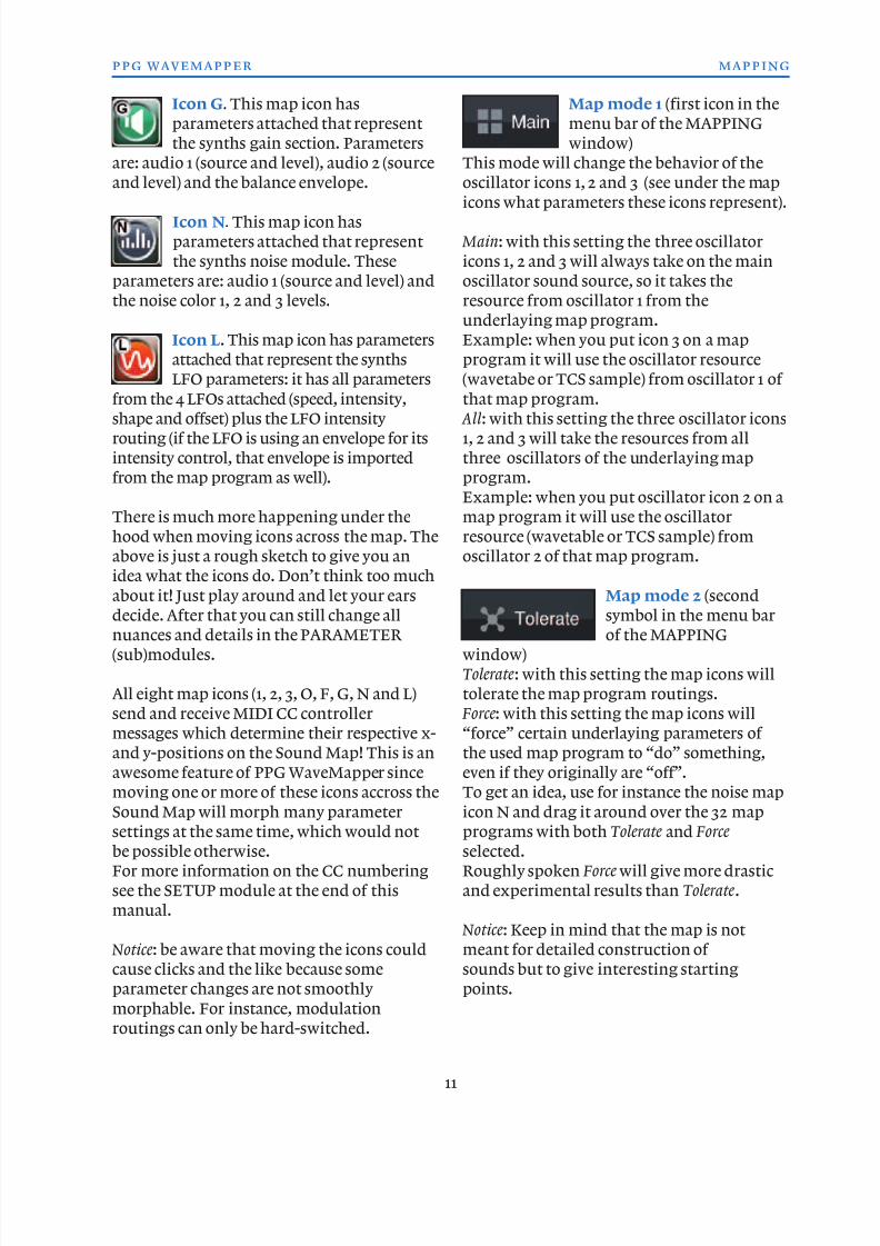
Icon G. This map icon has
parameters attached that represent
the synths gain section. Parameters
are: audio 1 (source and level), audio 2 (source
and level) and the balance envelope.
Icon N. This map icon has
parameters attached that represent
the synths noise module. These
parameters are: audio 1 (source and level) and
the noise color 1, 2 and 3 levels.
Icon L. This map icon has parameters
attached that represent the synths
LFO parameters: it has all parameters
from the 4 LFOs attached (speed, intensity,shape and offset) plus the LFO intensity
routing (if the LFO is using an envelope for its
intensity control, that envelope is imported
from the map program as well).
There is much more happening under the
hood when moving icons across the map. The
above is just a rough sketch to give you an
idea what the icons do. Don’t think too much
about it! Just play around and let your ears
decide. After that you can still change all
nuances and details in the PARAMETER
(sub)modules.
All eight map icons (1, 2, 3, O, F, G, N and L)
send and receive MIDI CC controller
messages which determine their respective x-
and y-positions on the Sound Map! This is an
awesome feature of PPG WaveMapper since
moving one or more of these icons accross the
Sound Map will morph many parametersettings at the same time, which would not
be possible otherwise.
For more information on the CC numbering
see the SETUP module at the end of this
manual.
Notice: be aware that moving the icons could
cause clicks and the like because some
parameter changes are not smoothly
morphable. For instance, modulationroutings can only be hard-switched.
Map mode 1 (first icon in the
menu bar of the MAPPING
window)
This mode will change the behavior of the
oscillator icons 1, 2 and 3 (see under the map
icons what parameters these icons represent).
Main: with this setting the three oscillator
icons 1, 2 and 3 will always take on the main
oscillator sound source, so it takes the
resource from oscillator 1 from the
underlaying map program.
Example: when you put icon 3 on a map
program it will use the oscillator resource
(wavetabe or TCS sample) from oscillator 1 of
that map program. All: with this setting the three oscillator icons
1, 2 and 3 will take the resources from all
three oscillators of the underlaying map
program.
Example: when you put oscillator icon 2 on a
map program it will use the oscillator
resource (wavetable or TCS sample) from
oscillator 2 of that map program.
Map mode 2 (second
symbol in the menu bar
of the MAPPING
window)
Tolerate: with this setting the map icons will
tolerate the map program routings.
Force: with this setting the map icons will
“force” certain underlaying parameters of
the used map program to “do” something,
even if they originally are “off”.
To get an idea, use for instance the noise map
icon N and drag it around over the 32 mapprograms with both Tolerate and Force
selected.
Roughly spoken Force will give more drastic
and experimental results than Tolerate.
Notice: Keep in mind that the map is not
meant for detailed construction of
sounds but to give interesting starting
points.
11
ppg wavemapper mapping
8/13/2019 WaveMapper Manual 1.0
http://slidepdf.com/reader/full/wavemapper-manual-10 12/50
Morphing slider: With
this slider you can set the
strength with which values
of parameters change when you drag a map
icon from one program to the other. Low
settings will give the smoothest morphingresults, while high settings will give more
abrupt transitions.
Random button
pressing this button will
spread the icons
randomly over the 32 map program
positions. Note that Main, All, Tolerate and
Force will be active as well.
Init root types 1
With this popup menu you
can select and place various
root program flavors on the map.
Init Atmos: will place atmospheric root
programs on the Sound Map.
Init Bass: will place bass root programs on the
Sound Map.
Init Efx: will place effect root programs on the
Sound Map.
Init Keys: will place key root programs on the
Sound Map.
Init Lead: will place lead root programs on the
Sound Map.
Init Pad: will place pad root programs on the
Sound Map.
Init Perc: will place percussion root programs
on the Sound Map.
Init Poly: will place poly root programs on the
Sound Map.
Init Vocal: will place vocal root programs onthe Sound Map.
Init Wave: will place wave root programs on
the Sound Map.
Init root types 2 and map editing
Init Synthetics: this will place some
synthetic root programs on the
Sound Map.
Init Instruments: this will place some
instrument root programs on the SoundMap.
Init Modulat: this will place some modulation
root programs on the Sound Map.
Init Splits : this wil place some split root
programs on the Sound Map.
Clear: clear all fields except the Base program
(upper left progam on the Sound Map).Copy: copy the Sound Map with 32 programs
from the selected preset program.
Paste: paste the copied Sound Map with 32
programs into the selected preset program.
Help: show info about the MAPPING module.
Map field options (double tap on one of the
32 map fields)
Load Root: will load a root program. Root
programs must be seen as exciters for thepreset program you are using or creating: its
not so important how the root program
sounds, but how useful it is on the map. The
names of the root programs always hints at
its goal: be it the resource of the oscillator,
the modulation settings etc.
Load Synt: this command loads the synthetic
root programs from the roots bank.
Load Inst: this command loads the analysed
instrument root programs from the roots
bank.
Load User: this gives the opportunity to load a
user (or factory) preset program as root
program.
Notice: since it is possible to use a preset
program as root program, it would be wise to
somehow mark those programs yourself (in
their names) for future clarity, so that you do
not accidently alter or delete them. Because
they could be used by more than one preset
program as root program a change or deletionwill change those preset programs as well!
Clear: this will clear the selected program
field on the map. When you put an icon on an
empty map program field it will use the
parameter settings from the base program
field (upper left map program field).
Bundle: a shortcut to make a selected map
program (being it a root- or preset program)
the source for all map icons.
Notice: the Main, All, Tolerate and Forceparameters are active too.
12
ppg wavemapper mapping
8/13/2019 WaveMapper Manual 1.0
http://slidepdf.com/reader/full/wavemapper-manual-10 13/50
Map icon shortcuts
When you press and hold a map icon, the app
will jump directly to the synthesizer module
section with the parameters that are
important for that map icon. I.e. if you press
and hold map icon 2 you will end up in the
PARAMETERS module -> oscillators sub
module -> Osc 2 section from where you can
directly edit its parameters in detail.
13
ppg wavemapper oscillators
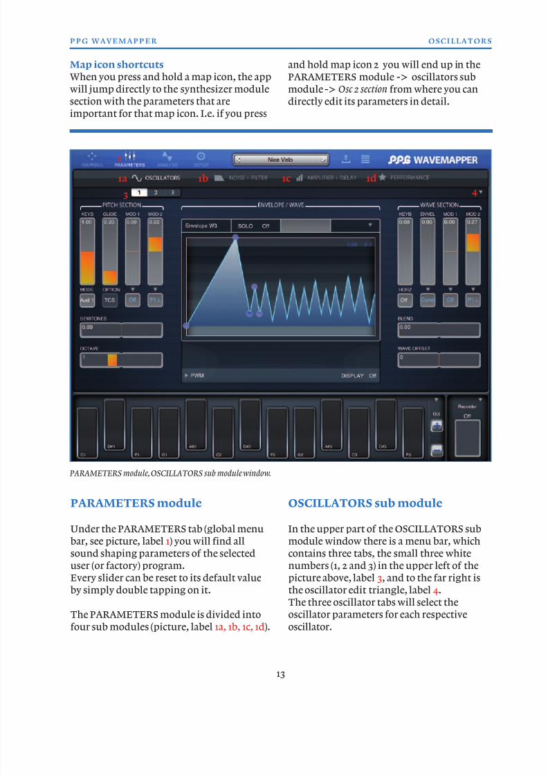
PARAMETERS module
Under the PARAMETERS tab (global menu
bar, see picture, label 1) you will find all
sound shaping parameters of the selected
user (or factory) program.
Every slider can be reset to its default value
by simply double tapping on it.
The PARAMETERS module is divided into
four sub modules (picture, label 1a, 1b, 1c, 1d).
OSCILLATORS sub module
In the upper part of the OSCILLATORS sub
module window there is a menu bar, which
contains three tabs, the small three white
numbers (1, 2 and 3) in the upper left of the
picture above, label 3, and to the far right is
the oscillator edit triangle, label 4.
The three oscillator tabs will select the
oscillator parameters for each respective
oscillator.
1
3 4
1a 1b 1c 1d
PARAMETERS module, OSCILLATORS sub module window.
8/13/2019 WaveMapper Manual 1.0
http://slidepdf.com/reader/full/wavemapper-manual-10 14/50
Edit triangle (label 4 in the picture on page
13)
Copy: this parameter let you make a copy of
the oscillator parameters (this is a “per
oscillator” copy function: you copy the
parameters of oscillator 1, 2 or 3. Paste: this parameter let you paste the copied
parameters into the selected oscillator.
Init : this parameter let you initialize the
parameters of the selected oscillator.
So the copy, paste and init parameter work on
one of the three oscillators (the one that is
selected).
Help: shows info about the OSCILLATORS
module.
The oscillator window is divided into three
sections: the Pitch section, the Envelope/Wave
section and the Wave section.
PITCH section
KEYB slider: this slider
controls the keyboard
tracking for the selected
oscillator. A value of zero gives no tracking.
This means that each
pressed key on the
keyboard will produce
the same oscillator
pitch. This can be
desirable when creating
FX sounds or when
using an oscillator as
LFO.A value of 1.00 will give
normal keyboard tracking.
Notice: the area around 1.00 is very sensible,
letting you define very fine detuning to the
keyboard scaling. This way it is is possible to
get a closer emulation of (old) analog
synthesizer behavior where for instance
keyboard tracking for the pitch could drift a
little because voltage controlled signals arenot like digital signals: they tend to fluctuate
over time due to various reasons
(temperature, tolerance of used components
etc.).
MODE select: with the MODE selector under
the KEYB slider you can choose one of threesettings:
Aud 1: suitable for playing lower pitched
sounds.
Aud 2: suitable for playing higher pitched
sounds.
The difference between these two settings is
that Aud 1 includes more overtones, than Aud 2,
so when playing high pitches, this may lead to
unwanted aliasing effects. In such a case Aud 2
may give better results. But its all up to yourtaste of course!
Sub: this setting makes the oscillator act on a
low frequency (even below audio, hence the
name Sub). With this setting you can use the
oscillator as a very sophisticated LFO in
modulation slots, since you can also modulate
the waveshape of the oscillator itself.
GLIDE speed slider: the glide speed slider
does exactly what it says: it changes the speed
of the glide effect. Low settings give a fast
glide effect, higher settings give a slower glide
effect. Notice that the glide works when
sliding horizontally over the keyboard when
touching and holding a key (legato). It also
works in mono MIDI mode when using an
external controller (see SETUP module
chapter for more info on MIDI settings).
OPTION select: the option select parameter
let you choose between TCS and Smpl.TCS: the oscillator resource will be played back
as TCS and can be modulated like a wavetable.
Smpl: the oscillator resource will be played
back like a normal sample, so with a 1:1
depency between the playback speed of the
sample and its frequency. This may be
preferable when the audio is too complex for
the TCS system or for creating sound effects.
The option select parameter is diconnected
when a wavetable is the resource for theoscillator.
14
ppg wavemapper oscillators
8/13/2019 WaveMapper Manual 1.0
http://slidepdf.com/reader/full/wavemapper-manual-10 15/50
MOD 1 modulation level slider: with this
slider you set the amount (positive or
negative) of pitch modulation by the selected
modulation source MOD 1 under the slider.
MOD 1 source select: here you select thepitch modulation source.
For oscillator 1 the modulation sources for
MOD 1 are:
N2: the noise from noise generator 2;
O3: the audio from oscillator 3 (remember,
when setting the oscillator MODE to Sub, this
source can act like a sophisticated LFO which
waveshape can be modulated itself as well);
N2 E: the envelope from noise generator 2;
N3 E: the envelope from noise generator 3;Off : no selection.
For oscillator 2 the modulation sources for
MOD 1 are:
N2: the noise from noise generator 2;
O3: the audio from oscillator 3 (remember,
when setting the oscillator MODE to Sub, this
source can act like a sophisticated LFO which
waveshape can be modulated itself as well);
N2 E: the envelope from noise generator 2;
N3 E: the envelope from noise generator 3;
Off : no selection.
For oscillator 3 the modulation sources for
MOD 1 are:
N2: the noise from noise generator 2;
O2: the audio from oscillator 2 (remember,
when setting the oscillator MODE to Sub, this
source can act like a sophisticated LFO which
waveshape can be modulated itself as well);
N2 E: the envelope from noise generator 2;
N3 E: the envelope from noise generator 3;
Off : no selection.
MOD 2 modulation level slider: with this
slider you set the amount (positive or
negative) of pitch modulation by the selected
modulation source MOD 2 under the slider.
MOD 2 source select: here you select the
pitch modulation source.
For oscillator 1 the modulation sources for
MOD 2 are: P1 L: the LFO from oscillator 1 pitch;
P1 E: the envelope from oscillator 1 pitch;
CX : controller from keyboard: horizontal
swipe after a key press;
CY : controller from keyboard: vertical swipe
after a key press;
Off , no selection.For oscillator 2 the modulation sources for
MOD 2 are:
P2 L: the LFO from oscillator 2 pitch;
P2 E: the envelope from oscillator 2 pitch;
CX : controller from keyboard: horizontal
swipe after a key press;
CY : controller from keyboard: vertical swipe
after a key press;
Off : no selection.
For oscillator 3 the modulation sources forMOD 2 are:
P3 L: the LFO from oscillator 3 pitch;
P3 E: the envelope from oscillator 3 pitch;
CX : controller from keyboard: horizontal
swipe after a key press;
CY : controller from keyboard: vertical swipe
after a key press;
Off : no selection.
SEMITONES slider: with this slider you can
fine tune the pitch of the selected oscillator.
The slider has a total range of -7/+7
semitones.
OCTAVE select slider: With this slider you
can change the octave setting of the selected
oscillator. It has a range of 9 octaves.
ENVELOPE / WAVE section
In the middle of the oscillators module
window we have the visualization of
envelopes, waveshapes (be it wavetables or
TCS files) and wave paths. See the picture on
the next page.
This is an important section for editing the
wavetable-, noise- and pitch-envelopes as
well for editing the wavetable paths.
You can also visualize the shape of the used
oscillator resource here.
15
ppg wavemapper oscillators
8/13/2019 WaveMapper Manual 1.0
http://slidepdf.com/reader/full/wavemapper-manual-10 16/50
Let’s take a closer look at the available
parameters.
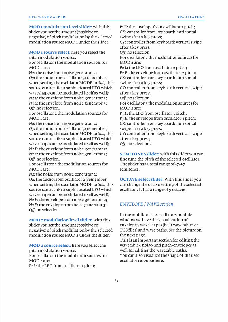
Envelope indication: in the upper left
corner of this middle section, you will see the
abbreviated name of the envelope that is
shown underneath it (upper left picture,
label 1). The envelope shown depends on thelast touched modulation source. For
instance, if you select N2 E as modulation
source in the MOD 1 slot of the pitch section,
the envelope of the noise 2 generator is
shown. In the picture above you see envelope
W3, being the wavetable envelope for
oscillator 3.
SOLO on/off : a handy shortcut to have only
the selected oscillator sounding. Notice: the setting will always reset to “off”
when changing the preset program or when
changing map icons in the MAPPING
module window.
Envelope edit triangle (upper left picture 2)
Here we find edit parameters for the selected
envelope.
Copy: copies the envelope parameters.
Paste: will paste the copied envelopeparameters.
Set Loop/Kill Loop: will set a default loop for the
selected envelope or will kill the loop when it
is on.
Notice: gain envelopes can not have a loop.
Default Init : will set default envelope settings
for the selected envelope. Spread Points : will spread the envelope points
more each time it is selected.
Help: shows information about the envelopes.
Oscillator resource selection triangle
(picture on the left, label 3)
In the ENVELOPE/WAVE window in the
oscillator section we find on the lower left
corner a popup menu where the name of the
selected oscillator resource is printed andwhere you can choose different resources for
each oscillator. All available factory and user
wavetables and TCS files can be selected here.
Each oscillator can have a different resource
selected.
Newly created wavetables and/or TCS files in
the ANALYSE page will also become available
here. The various sections in the popup menu
are:
WTS: factory wavetables;
TCS: factory TCS files; SndD: Sound Designer wavetables and TCS
files;
User : User wavetables and TCS files.
You can jump directly to one of those sections
by tapping on the grey abbreviations on the
right side of the popu menu.
Notice: by selecting a new wavetable the
eventual existing wavetable path will be reset
to its default, being a linear path from the firstto the last wave in the selected wavetable. More
on wavetable paths later.
Display on/off
Off: In off-mode the shape of the envelope is
shown in the window.
On: when set to on, the waveshape of the
wavetable or TCS is drawn.
Notice: when Display is set to on and theoscillator has a wavetable as resource that is
16
ppg wavemapper oscillators
Envelope points with which you can change the shape of the
envelope. In this case it is a looped envelope.
1 2
3
8/13/2019 WaveMapper Manual 1.0
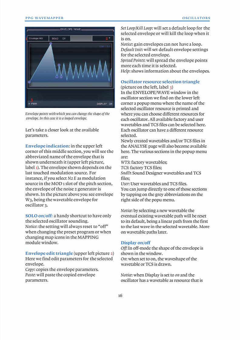
http://slidepdf.com/reader/full/wavemapper-manual-10 17/50
played with a linear path, you will see this path
under the wave drawing (yellow to orange bar,
upper left picture on this page). You can edit
the start and end point of this path by tapping
and holding and then sliding the start or end
point of the bar to the left or the right.
When you do not see that bar, the oscillator isplaying a non-linear path. This is also visible in
the grey rectangle above the wave drawing: it
reads complex in that last situation (upper right
picture, label 1). Otherwise it reads linear , or
when it is a TCS resource it reads TCS. The
number in the grey rectangle shows the
number of periodes or waves.
Between the grey info-rectangle and wave
wave(table) drawing there is another grey bar,where you might see a green point moving
horizontally when you play the keys (see
picture to the right, label 1).
The green point represents the position of the
wave envelope of the selected oscillator within
the selected part of of the wavetable or TCS
file. Per default the grey bar and the
yellow/orange bar defining the wave path have
the same position. However, the grey bar can
have an offset by a changed wave offset settingor changed wave keyboard setting.
For the following explanations please change
to the preset Vocals . Oscillator 3 is selected,
and you see that it uses the Vowel aa bg
resource. Now set the SOLO switch to On and
also the DISPLAY switch. The gray info field
on top of the wave-display shows 64 / linear ,
which means the wavetable contains 64
single waves and uses a linear path. This pathis shown by the orange bar in the lower part
of the display. Please swipe the wave to the
left, to see that bar. The bar covers a range
from wave 50 to 60. This is the range which
the envelope controls.
17
ppg wavemapper oscillators
1
Wavetable drawing with lineair path from wave point 1 to 12
(the grey/yellow bar under the drawing)
Wavetable with complex path (1).
1
8/13/2019 WaveMapper Manual 1.0
http://slidepdf.com/reader/full/wavemapper-manual-10 18/50
But now the parameter KEYB (inside the
wave section) comes into play. This allows for
an additional offset for the envelope
control. If you set this para to zero, and play
some notes, you see, that the gray frame in
the upper part of the display stays at thesame position as the yellow bar. Now if you
increase the KEYB value, you will find that
the gray frame shifts to different positions
according to the keys you play. This in fact
is important to get the feeling of a constant
vowel /aa/ to sound.
You may have already noticed, the green
light point inside the gray frame is an
indicator for the envelope position. Theenvelope is always limited inside the frame.
But the frame itself maybe offset by the
KEYB parameter and also by the WAVE
OFFSET parameter.
Overall envelope usage
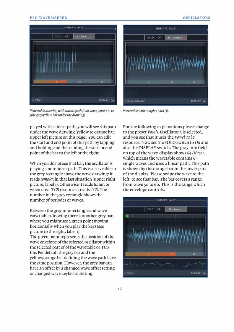
When an envelope is shown in the view
window, you can edit the envelope points
(picture below, label 1) by tapping and
holding those points and slide them over
the screen. You can also change the shape of
various envelope stages (attack, decay and
release) by touching and holding the lines
between the envelope points and then drag
them up or down (picture below, label 2).
Notice: This feature should not be
underestimated! The character of a sound
depends a lot on how various levels of amplifier-, filter cutoff-, or pitch-modulation
rise or decay.
For instance: a linear pitch or amplifier level
modulation in the attack phase of the
modulating envelope can give very different
results compared to a non-linear shape.
We recommend experimenting with it a lot.
It can make or break your sound.
The small blue numbers in the upper right of the envelope drawing window (picture below,
label 3) give some information about the
velocity attenuation (you can change the value
by tapping on the first number and sliding
up/down the value) and information about
the duration of the selected envelope, which is
the right number (this value will change when
you drag one of the envelope time-points to
the right out of the window or to the left).
There are 13 different envelopes available in
PPG WaveMapper, which are accessable in
the various synth modules. Each envelope
has a main target destination, but some of
them also appear in modulation slots as a
modulation source for other destinations.
The 13 envelopes are:
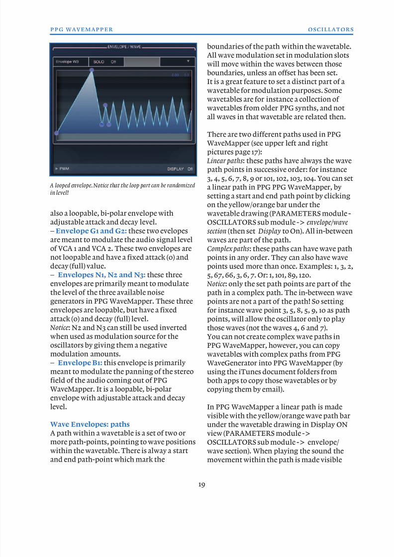
– Envelope W1, W2 and W3: the so-called
wave envelopes, because they are primarily
meant to modulate the wavetable or TCSwaveshape of each oscillator. These are
loopable, bi-polar envelopes with an
adjustable attack and decay level.
– Envelope P1, P2 and P3: the so-called
pitch envelopes, because they are primarily
meant to modulate the pitch of each of the
three oscillators. These are also loopable, bi-
polar envelopes with an adjustable attack
and decay level.
– Envelope F1: the filter envelope, primarilymeant to modulate the filter cutoff. This is
18
ppg wavemapper oscillators
Envelope points with which you can change the shape of theenvelope.
1
1
1 1
2
3
8/13/2019 WaveMapper Manual 1.0
http://slidepdf.com/reader/full/wavemapper-manual-10 19/50
also a loopable, bi-polar envelope with
adjustable attack and decay level.
– Envelope G1 and G2: these two evelopes
are meant to modulate the audio signal level
of VCA 1 and VCA 2. These two envelopes are
not loopable and have a fixed attack (0) and
decay (full) value.
– Envelopes N1, N2 and N3: these three
envelopes are primarily meant to modulate
the level of the three available noise
generators in PPG WaveMapper. These three
envelopes are loopable, but have a fixed
attack (0) and decay (full) level.
Notice: N2 and N3 can still be used inverted
when used as modulation source for the
oscillators by giving them a negative
modulation amounts.
– Envelope B1: this envelope is primarilymeant to modulate the panning of the stereo
field of the audio coming out of PPG
WaveMapper. It is a loopable, bi-polar
envelope with adjustable attack and decay
level.
Wave Envelopes: paths
A path within a wavetable is a set of two or
more path-points, pointing to wave positions
within the wavetable. There is alway a startand end path-point which mark the
boundaries of the path within the wavetable.
All wave modulation set in modulation slots
will move within the waves between those
boundaries, unless an offset has been set.
It is a great feature to set a distinct part of a
wavetable for modulation purposes. Somewavetables are for instance a collection of
wavetables from older PPG synths, and not
all waves in that wavetable are related then.
There are two different paths used in PPG
WaveMapper (see upper left and right
pictures page 17):
Linear paths : these paths have always the wave
path points in successive order: for instance
3, 4, 5, 6, 7, 8, 9 or 101, 102, 103, 104. You can seta linear path in PPG PPG WaveMapper, by
setting a start and end path point by clicking
on the yellow/orange bar under the
wavetable drawing (PARAMETERS module -
OSCILLATORS sub module -> envelope/wave
section (then set Display to On). All in-between
waves are part of the path.
Complex paths : these paths can have wave path
points in any order. They can also have wave
points used more than once. Examples: 1, 3, 2,
5, 67, 66, 3, 6, 7. Or: 1, 101, 89, 120.
Notice: only the set path points are part of the
path in a complex path. The in-between wave
points are not a part of the path! So setting
for instance wave point 3, 5, 8, 5, 9, 10 as path
points, will allow the oscillator only to play
those waves (not the waves 4, 6 and 7).
You can not create complex wave paths in
PPG WaveMapper, however, you can copy
wavetables with complex paths from PPG
WaveGenerator into PPG WaveMapper (byusing the iTunes document folders from
both apps to copy those wavetables or by
copying them by email).
In PPG WaveMapper a linear path is made
visible with the yellow/orange wave path bar
under the wavetable drawing in Display ON
view (PARAMETERS module ->
OSCILLATORS sub module -> envelope/
wave section). When playing the sound themovement within the path is made visible
19
ppg wavemapper oscillators
A looped envelope. Notice that the loop part can be randomized
in level!
8/13/2019 WaveMapper Manual 1.0
http://slidepdf.com/reader/full/wavemapper-manual-10 20/50
with the bar above the wavetable drawing in
Display ON view: you will see a green dot
move around the wave path according to the
wave modulation set for that wavetable
So, the green light point inside the gray
frame is an indicator for the envelopeposition. The envelope is always limited
inside the frame. But the frame itself may be
offset by the KEYB parameter and/or by the
WAVE OFFSET parameter.
You can reset a complex path in a selected
wavetable into a linear path by simply
editing the wave path bar.
When you think a wave modulation is notacting as expected, or even not working at all,
it is almost certain that the set wavepath for
that oscillator is the cause of that.
A newly selected wavetable in the
PARAMETERS module ->OSCILLATORS
sub module > envelope/wave section under
the Resource selection triangle popup menu
will always set the wavetable path to its
default, being a linear path from the start
wave to the end wave of that wavetable.
Envelope points: envelope G1, G2, N1, N2,
N3
These envelopes have three envelope points
that can be moved:
The first envelope point sets the attack time;
The second envelope point sets the decay;
time and the sustain level;
The third envelope point sets the release time.
Envelope points in non-looped
envelopes: W1, W2, W3, P1, P2, P3, F1, B1
These envelopes have four envelope points
that can be moved.
The first envelope point: sets the base level
for the complete envelope starting without
changing the peak level;
The second envelope point sets the attack
time and the decay start level;
The third envelope point sets the decay timeand the sustain level;
The fourth envelope point sets the release
time and the base level while maintaining
the overall level range.
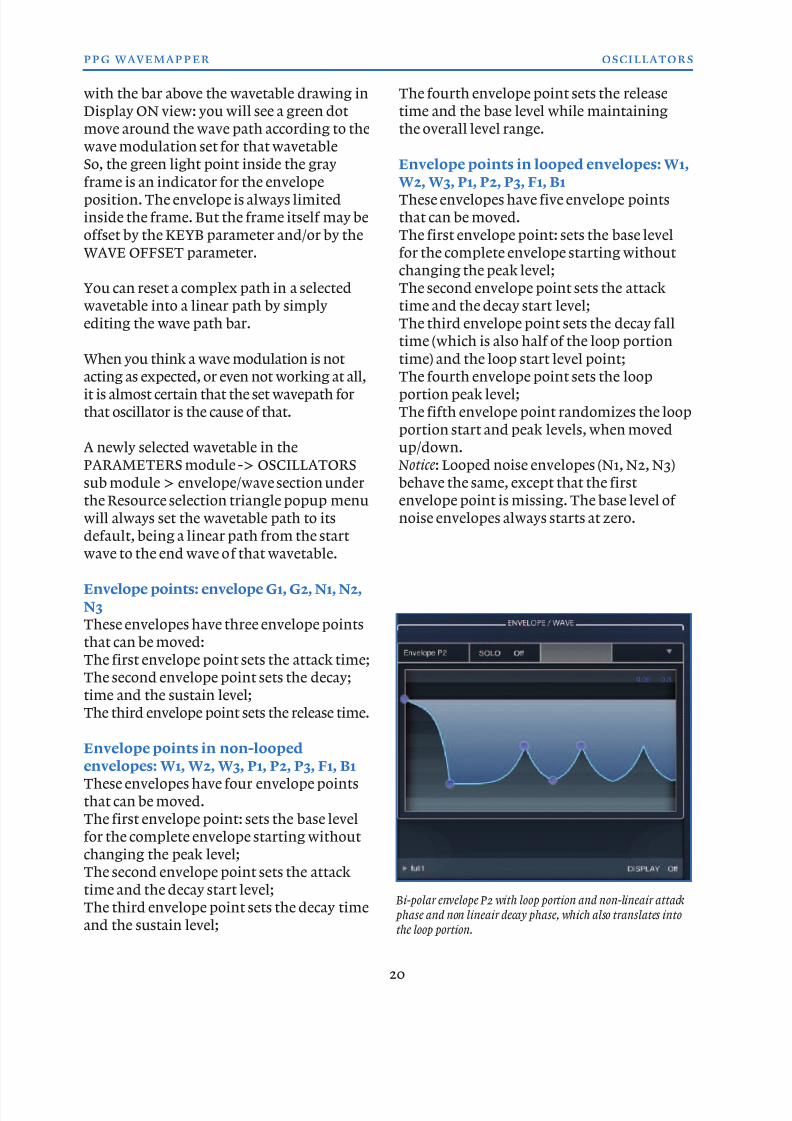
Envelope points in looped envelopes: W1,
W2, W3, P1, P2, P3, F1, B1These envelopes have five envelope points
that can be moved.
The first envelope point: sets the base level
for the complete envelope starting without
changing the peak level;
The second envelope point sets the attack
time and the decay start level;
The third envelope point sets the decay fall
time (which is also half of the loop portion
time) and the loop start level point;The fourth envelope point sets the loop
portion peak level;
The fifth envelope point randomizes the loop
portion start and peak levels, when moved
up/down.
Notice: Looped noise envelopes (N1, N2, N3)
behave the same, except that the first
envelope point is missing. The base level of
noise envelopes always starts at zero.
20
ppg wavemapper oscillators
Bi-polar envelope P2 with loop portion and non-lineair attack
phase and non lineair decay phase, which also translates intothe loop portion.
8/13/2019 WaveMapper Manual 1.0
http://slidepdf.com/reader/full/wavemapper-manual-10 21/50
WAVE section
In thise section of the
oscillator window you
will find parameters
that influence the waya wavetable or TCS is
played back.
KEYB slider: this
slider sets the
keyboard tracking for
the wavetable or TCS
position.
HORZ: this paremetersets a lock for 16 steps
each time when you change the WAVE
OFFSET parameter value. When HORZ is set
to on the wavetable keeps the path start
position until the WAVE OFFSET value
reaches 17, 33, 49 (or -17, -33, -49). Then it
jumps forth (or back) 16 positions in the
wavetable. This is for instance handy when
dealing with wavetables that are build up out
of sets of 16 and/or 32 and/or 48 and/or 64
waves. take for instance a look at the wave
drawings of wavetable full1 or full2: you can
clearly see big changes between wave 16/17
( full1), wave 48/49 ( full1) or wave 32/33 ( full2).
This parameter makes switching between
those positions easier.
ENVEL slider: this slider sets the amount of
wave envelope modulation (ENVEL select
checkbox under the slider is set to W1 E) or
the amount of a fixed level on the waveposition of the selected oscillator (ENVEL
select is Const ).
Zero means no modulation (ENVEL select is
W1 E) or first wave of the wavetable (ENVEL
select is Const ), 1.00 means full modulation
(ENVEL select is W1 E) or the last wave of the
wavetable (ENVEL select is Const ).
ENVEL select: E1 W or Const . See the
description of the ENVEL slider above.
MOD 1 bi-level slider: with this slider you
set the amount (positive or negative) of wave
position modulation by the selected
modulation source MOD 1.
MOD 1 source select: here you select thewave position modulation source.
For oscillator 1 the modulation sources for
MOD 1 are:
O3: the audio from oscillator 3 (remember,
when setting the oscillator MODE to Sub, this
source can act like a sophisticated LFO which
waveshape can be modulated itself as well)
CX : controller from keyboard: horizontal
swipe after a key press.
CY : controller from keyboard: vertical swipeafter a key press.
CV : controller from velocity: the vertical
position on the key you play.
Off ,: no selection.
For oscillator 2 the modulation sources for
MOD 1 are:
O3: the audio from oscillator 3 (remember,
when setting the oscillator MODE to Sub,
this source can act like a sophisticated LFO
which waveshape can be modulated itself as
well)
CX : controller from keyboard: horizontal
swipe after a key press.
CY : controller from keyboard: vertical swipe
after a key press.
CV : controller from velocity: the vertical
position on the key you play.
Off : no selection.
For oscillator 3 the modulation sources for
MOD 1 are:
O2: the audio from oscillator 2 (remember,when setting the oscillator MODE to Sub,
this source can act like a sophisticated LFO
which waveshape can be modulated itself as
well).
CX : controller from keyboard: horizontal
swipe after a key press.
CY : controller from keyboard: vertical swipe
after a key press.
CV : controller from velocity: the vertical
position on the key you play.Off : no selection.
21
ppg wavemapper oscillators
8/13/2019 WaveMapper Manual 1.0
http://slidepdf.com/reader/full/wavemapper-manual-10 22/50
MOD 2 bi-level slider: with this slider you
set the amount (positive or negative) of wave
position modulation by the selected
modulation source MOD 2.
MOD 2 source select: here you select thewave position modulation source.
For oscillator 1 the modulation sources for
MOD 2 are:
P1 L: the LFO from oscillator 1 pitch.
CX : Controller from keyboard: horizontal
swipe after a key press.
CY : Controller from keyboard: vertical swipe
after a key press.
CV : Controller from velocity: the vertical
position on the key you play.Off : no selection.
For oscillator 2 the modulation sources for
MOD 2 are:
P2 L: the LFO from oscillator 2 pitch.
CX : Controller from keyboard: horizontal
swipe after a key press.
CY : Controller from keyboard: vertical swipe
after a key press.
CV : Controller from velocity: the vertical
position on the key you play.
Off : no selection.
For oscillator 3 the modulation sources for
MOD 2 are:
P3 L: the LFO from oscillator 3 pitch.
CX : Controller from keyboard: horizontalswipe after a key press.
CY : Controller from keyboard: vertical swipe
after a key press.
CV : Controller from velocity: the vertical
position on the key you play.
Off : no selection.
BLEND: this parameter set the morphing
amount between waves in a wavetable. When
zero the transitions between the waves willbe smooth, when set to 1.00 the transition
will be much more abrupt. Higher settings
will emulate the first PPG hardware
synthesizers more acurately.
WAVE OFFSET: this parameter sets an offset
for the wave start position. See also the
HORIZ parameter described earlier. The
range goes from -50 to +50.
22
ppg wavemapper oscillators
8/13/2019 WaveMapper Manual 1.0
http://slidepdf.com/reader/full/wavemapper-manual-10 23/50
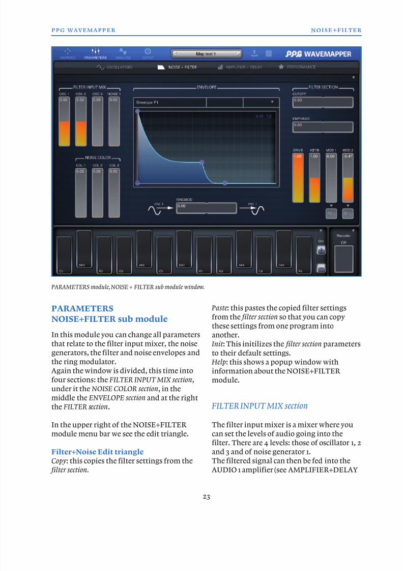
PARAMETERS
NOISE+FILTER sub module
In this module you can change all parameters
that relate to the filter input mixer, the noise
generators, the filter and noise envelopes and
the ring modulator.
Again the window is divided, this time intofour sections: the FILTER INPUT MIX section,
under it the NOISE COLOR section, in the
middle the ENVELOPE section and at the right
the FILTER section.
In the upper right of the NOISE+FILTER
module menu bar we see the edit triangle.
Filter+Noise Edit triangle
Copy: this copies the filter settings from the
filter section.
Paste: this pastes the copied filter settings
from the filter section so that you can copy
these settings from one program into
another.
Init : This initilizes the filter section parameters
to their default settings.
Help: this shows a popup window with
information about the NOISE+FILTER module.
FILTER INPUT MIX section
The filter input mixer is a mixer where you
can set the levels of audio going into the
filter. There are 4 levels: those of oscillator 1, 2
and 3 and of noise generator 1.
The filtered signal can then be fed into the
AUDIO 1 amplifier (see AMPLIFIER+DELAY
23
ppg wavemapper noise+filter
PARAMETERS module, NOISE + FILTER sub module window.
8/13/2019 WaveMapper Manual 1.0
http://slidepdf.com/reader/full/wavemapper-manual-10 24/50
module). This is the
most common way for
the audio path of a
synthesizer: oscs ->
mixer - filter ->
amplifier.
Notice: all audio
(filtered or not) goes through the echo/delay
FX before it reaches the amplifiers.
Notice: the summed audio signal that is
coming out of the filter input mixer section
can also be taken directly, without going
through the filter, and be fed into VCA 1
and/or VCA 2. You should select Mix then asaudio source for VCA 1 and/or VCA 2. See the
AMPLIFIER+DELAY module for more
information.
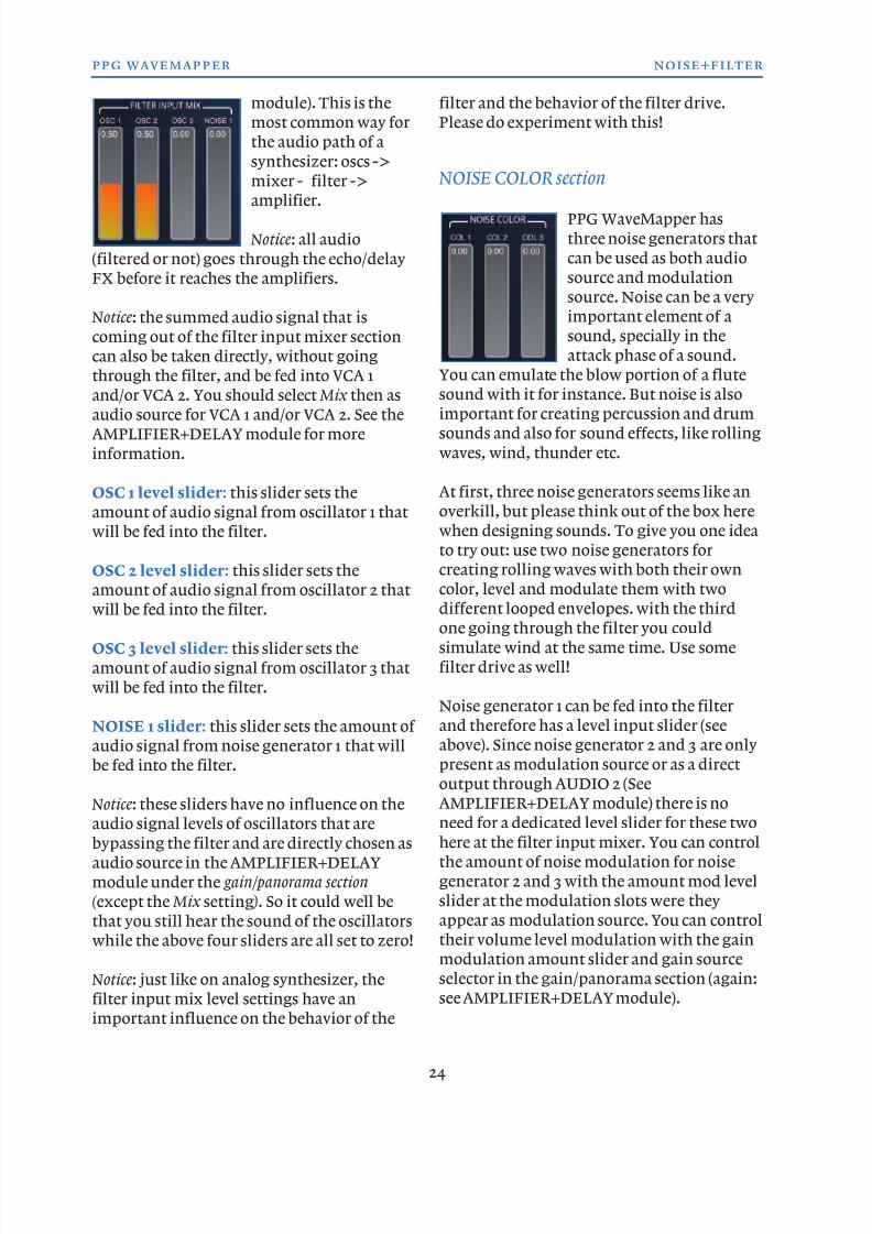
OSC 1 level slider: this slider sets the
amount of audio signal from oscillator 1 that
will be fed into the filter.
OSC 2 level slider: this slider sets the
amount of audio signal from oscillator 2 that
will be fed into the filter.
OSC 3 level slider: this slider sets the
amount of audio signal from oscillator 3 that
will be fed into the filter.
NOISE 1 slider: this slider sets the amount of
audio signal from noise generator 1 that will
be fed into the filter.
Notice: these sliders have no influence on theaudio signal levels of oscillators that are
bypassing the filter and are directly chosen as
audio source in the AMPLIFIER+DELAY
module under the gain/panorama section
( except the Mix setting ). So it could well be
that you still hear the sound of the oscillators
while the above four sliders are all set to zero!
Notice: just like on analog synthesizer, the
filter input mix level settings have animportant influence on the behavior of the
filter and the behavior of the filter drive.
Please do experiment with this!
NOISE COLOR section
PPG WaveMapper has
three noise generators that
can be used as both audio
source and modulation
source. Noise can be a very
important element of a
sound, specially in the
attack phase of a sound.
You can emulate the blow portion of a flute
sound with it for instance. But noise is alsoimportant for creating percussion and drum
sounds and also for sound effects, like rolling
waves, wind, thunder etc.
At first, three noise generators seems like an
overkill, but please think out of the box here
when designing sounds. To give you one idea
to try out: use two noise generators for
creating rolling waves with both their own
color, level and modulate them with two
different looped envelopes. with the thirdone going through the filter you could
simulate wind at the same time. Use some
filter drive as well!
Noise generator 1 can be fed into the filter
and therefore has a level input slider (see
above). Since noise generator 2 and 3 are only
present as modulation source or as a direct
output through AUDIO 2 (See
AMPLIFIER+DELAY module) there is noneed for a dedicated level slider for these two
here at the filter input mixer. You can control
the amount of noise modulation for noise
generator 2 and 3 with the amount mod level
slider at the modulation slots were they
appear as modulation source. You can control
their volume level modulation with the gain
modulation amount slider and gain source
selector in the gain/panorama section (again:
see AMPLIFIER+DELAY module).
24
ppg wavemapper noise+filter
8/13/2019 WaveMapper Manual 1.0
http://slidepdf.com/reader/full/wavemapper-manual-10 25/50
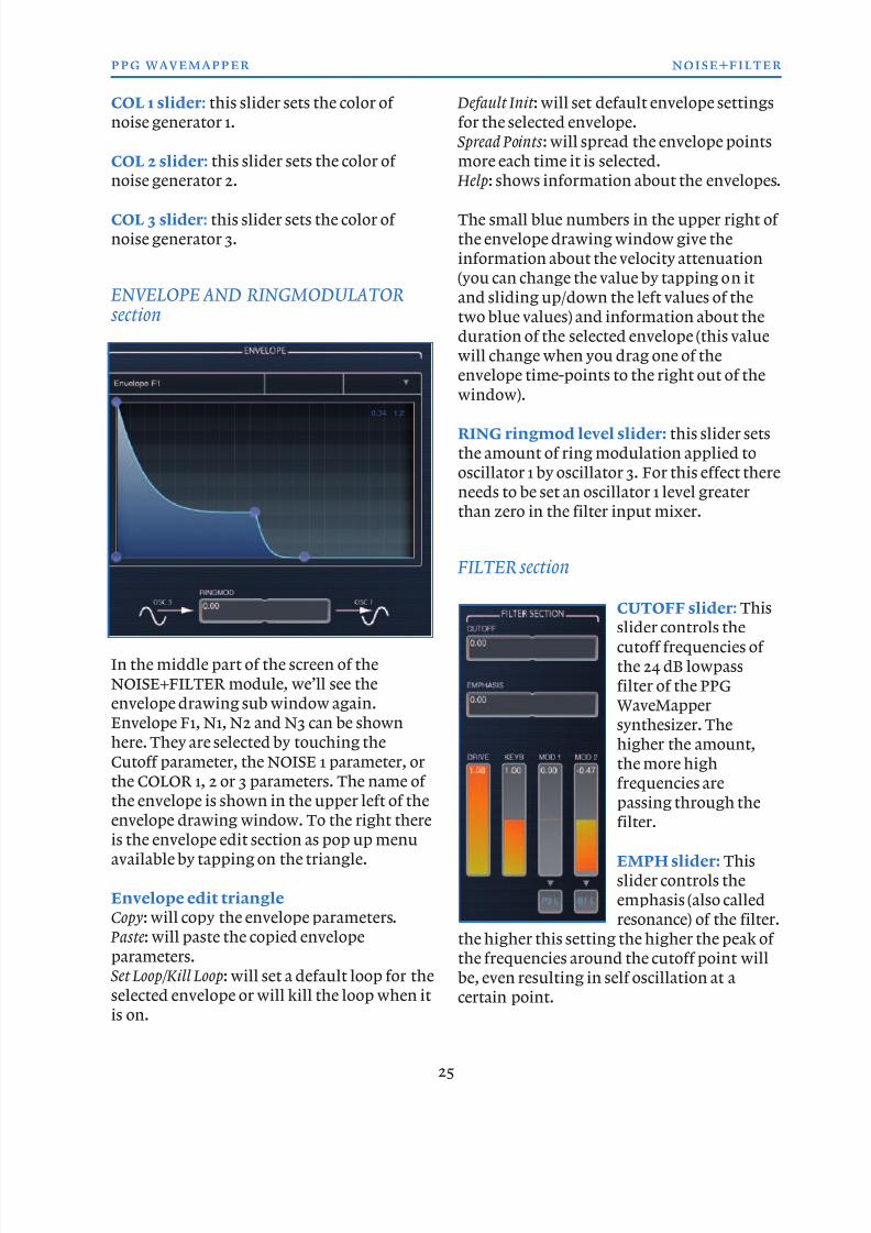
COL 1 slider: this slider sets the color of
noise generator 1.
COL 2 slider: this slider sets the color of
noise generator 2.
COL 3 slider: this slider sets the color of
noise generator 3.
ENVELOPE AND RINGMODULATORsection
In the middle part of the screen of the
NOISE+FILTER module, we’ll see the
envelope drawing sub window again.
Envelope F1, N1, N2 and N3 can be shown
here. They are selected by touching the
Cutoff parameter, the NOISE 1 parameter, or
the COLOR 1, 2 or 3 parameters. The name of
the envelope is shown in the upper left of theenvelope drawing window. To the right there
is the envelope edit section as pop up menu
available by tapping on the triangle.
Envelope edit triangle
Copy: will copy the envelope parameters.
Paste: will paste the copied envelope
parameters.
Set Loop/Kill Loop: will set a default loop for the
selected envelope or will kill the loop when it
is on.
Default Init : will set default envelope settings
for the selected envelope.
Spread Points : will spread the envelope points
more each time it is selected.
Help: shows information about the envelopes.
The small blue numbers in the upper right of
the envelope drawing window give the
information about the velocity attenuation
(you can change the value by tapping on it
and sliding up/down the left values of the
two blue values) and information about the
duration of the selected envelope (this value
will change when you drag one of the
envelope time-points to the right out of the
window).
RING ringmod level slider: this slider sets
the amount of ring modulation applied to
oscillator 1 by oscillator 3. For this effect there
needs to be set an oscillator 1 level greater
than zero in the filter input mixer.
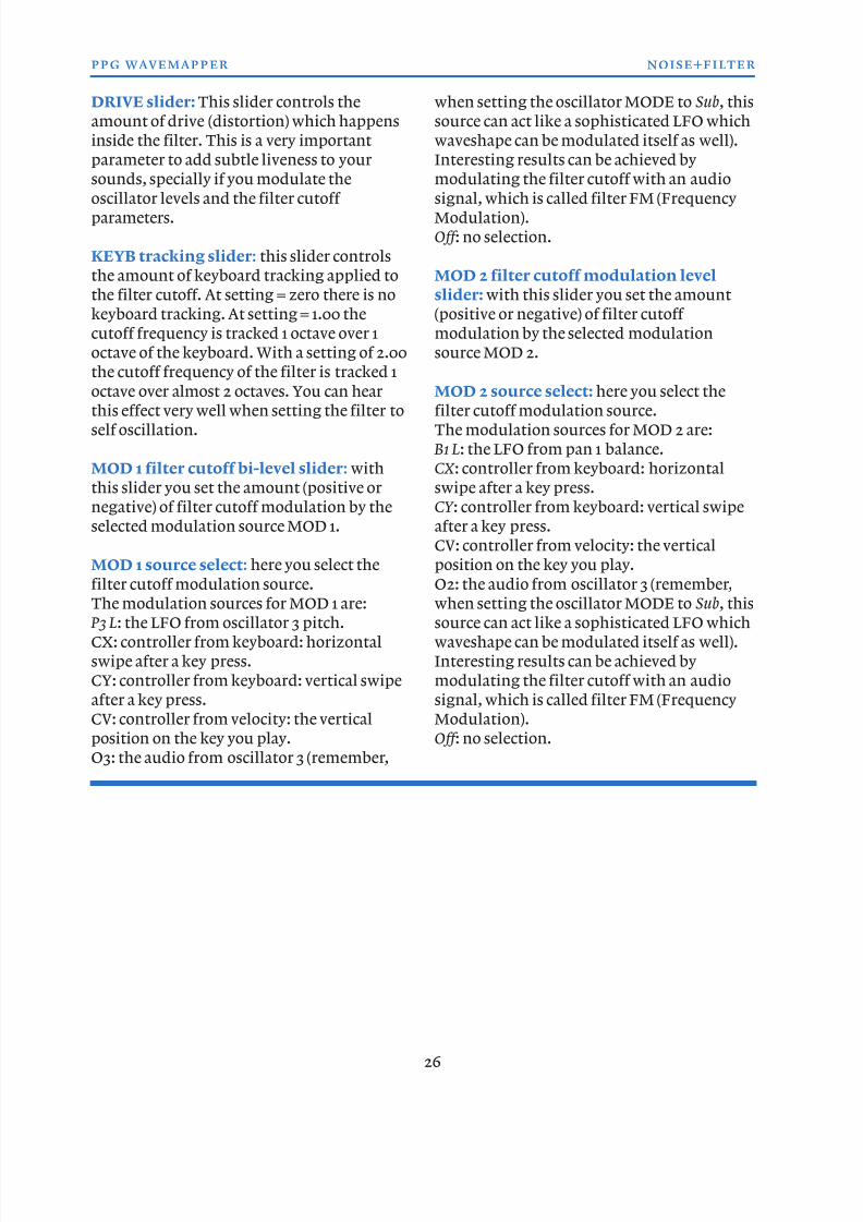
FILTER section
CUTOFF slider: Thisslider controls the
cutoff frequencies of
the 24 dB lowpass
filter of the PPG
WaveMapper
synthesizer. The
higher the amount,
the more high
frequencies are
passing through thefilter.
EMPH slider: This
slider controls the
emphasis (also called
resonance) of the filter.
the higher this setting the higher the peak of
the frequencies around the cutoff point will
be, even resulting in self oscillation at a
certain point.
25
ppg wavemapper noise+filter
8/13/2019 WaveMapper Manual 1.0
http://slidepdf.com/reader/full/wavemapper-manual-10 26/50
DRIVE slider: This slider controls the
amount of drive (distortion) which happens
inside the filter. This is a very important
parameter to add subtle liveness to your
sounds, specially if you modulate the
oscillator levels and the filter cutoff parameters.
KEYB tracking slider: this slider controls
the amount of keyboard tracking applied to
the filter cutoff. At setting = zero there is no
keyboard tracking. At setting = 1.00 the
cutoff frequency is tracked 1 octave over 1
octave of the keyboard. With a setting of 2.00
the cutoff frequency of the filter is tracked 1
octave over almost 2 octaves. You can hearthis effect very well when setting the filter to
self oscillation.
MOD 1 filter cutoff bi-level slider: with
this slider you set the amount (positive or
negative) of filter cutoff modulation by the
selected modulation source MOD 1.
MOD 1 source select: here you select the
filter cutoff modulation source.
The modulation sources for MOD 1 are:
P3 L: the LFO from oscillator 3 pitch.
CX: controller from keyboard: horizontal
swipe after a key press.
CY: controller from keyboard: vertical swipe
after a key press.
CV: controller from velocity: the vertical
position on the key you play.
O3: the audio from oscillator 3 (remember,
when setting the oscillator MODE to Sub, this
source can act like a sophisticated LFO which
waveshape can be modulated itself as well).
Interesting results can be achieved by
modulating the filter cutoff with an audio
signal, which is called filter FM (FrequencyModulation).
Off : no selection.
MOD 2 filter cutoff modulation level
slider: with this slider you set the amount
(positive or negative) of filter cutoff
modulation by the selected modulation
source MOD 2.
MOD 2 source select: here you select thefilter cutoff modulation source.
The modulation sources for MOD 2 are:
B1 L: the LFO from pan 1 balance.
CX : controller from keyboard: horizontal
swipe after a key press.
CY : controller from keyboard: vertical swipe
after a key press.
CV: controller from velocity: the vertical
position on the key you play.
O2: the audio from oscillator 3 (remember,
when setting the oscillator MODE to Sub, this
source can act like a sophisticated LFO which
waveshape can be modulated itself as well).
Interesting results can be achieved by
modulating the filter cutoff with an audio
signal, which is called filter FM (Frequency
Modulation).
Off : no selection.
26
ppg wavemapper noise+filter
8/13/2019 WaveMapper Manual 1.0
http://slidepdf.com/reader/full/wavemapper-manual-10 27/50
PARAMETERSAMPLIFIER + DELAY sub module
In this module you can edit all parameters
that have effect on the synths amplifiers, the
gain and balance envelopes and on the
Echo/Delay effects.
We start again in the upper right corner of
the menu bar of the AMPLIFIER +DELAY
module.
Page Edit triangle
Copy: copies the VCA parameters.
Paste: pasts the copie VCA parameters.
Init : inits the VCA parameters to its default
settings.
Panning : inits the Panning parameters to its
default settings.
Help: shows information on the AMPLIFIER+
DELAY parameters.
GAIN/PANORAMA section
In this section you will find all parameters
with which you can edit the two amplifiers
and the panning. Although the PPG
WaveMapper synthesizer engine has a mono
signal path (except for the echo/delay ->VCA
-> panning), at the end of that path you can
create stereo effects.
The synthesizer engine has two so called
VCAs (VCA stands for Voltage Controlled
Amplifier and this name comes from the
analog synthesizers area). The two amplifiers
can be fed with various audio signals, where
the panning can, together with the stereo
27
ppg wavemapper amplifier+delay
PARAMETERS module, AMPLIFIER +DELAY sub module window.
8/13/2019 WaveMapper Manual 1.0
http://slidepdf.com/reader/full/wavemapper-manual-10 28/50
echo/delay processor
create nice stereo
effects.
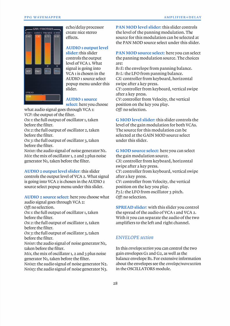
AUDIO 1 output level
slider: this slidercontrols the output
level of VCA 1. What
signal is going into
VCA 1 is chosen in the
AUDIO 1 source select
popup menu under this
slider.
AUDIO 1 source
select: here you choosewhat audio signal goes through VCA 1:
VCF: the output of the filter.
Osc 1: the full output of oscillator 1, taken
before the filter.
Osc 2: the full output of oscillator 2, taken
before the filter.
Osc 3: the full output of oscillator 3, taken
before the filter.
Noise1: the audio signal of noise generator N1.
Mix : the mix of oscillator 1, 2 and 3 plus noise
generator N1, taken before the filter.
AUDIO 2 output level slider: this slider
controls the output level of VCA 2. What signal
is going into VCA 2 is chosen in the AUDIO 2
source select popup menu under this slider.
AUDIO 2 source select: here you choose what
audio signal goes through VCA 2:
Off : no selection.
Osc 1: the full output of oscillator 1, takenbefore the filter.
Osc 2: the full output of oscillator 2, taken
before the filter.
Osc 3: the full output of oscillator 3, taken
before the filter.
Noise1: the audio signal of noise generator N1,
taken before the filter.
Mix , the mix of oscillator 1, 2 and 3 plus noise
generator N1, taken before the filter.
Noise2: the audio signal of noise generator N2. Noise3: the audio signal of noise generator N3.
PAN MOD level slider: this slider controls
the level of the panning modulation. The
source for this modulation can be selected at
the PAN MOD source select under this slider.
PAN MOD source select: here you can selectthe panning modulation source. The choices
are:
B1 E: the envelope from panning balance.
B1 L: the LFO from panning balance.
CX: controller from keyboard, horizontal
swipe after a key press.
CY: controller from keyboard, vertical swipe
after a key press.
CV: controller from Velocity, the vertical
position on the key you play.Off: no selection.
G MOD level slider: this slider controls the
level of the gain modulation for both VCAs.
The source for this modulation can be
selected at the GAIN MOD source select
under this slider.
G MOD source select: here you can select
the gain modulation source.
CX : controller from keyboard, horizontal
swipe after a key press.
CY : controller from keyboard, vertical swipe
after a key press.
CV : controller from Velocity, the vertical
position on the key you play.
P3 L: the LFO from oscillator 3 pitch.
Off : no selection.
SPREAD slider: with this slider you control
the spread of the audio of VCA 1 and VCA 2.With it you can separate the audio of the two
amplifiers to the left and right channel.
ENVELOPE section
In this envelope section you can control the two
gain envelopes G1 and G2, as well as the
balance envelope B1. For extensive information
about the envelopes see the envelope/wave sectionin the OSCILLATORS module.
28
ppg wavemapper amplifier+delay
8/13/2019 WaveMapper Manual 1.0
http://slidepdf.com/reader/full/wavemapper-manual-10 29/50
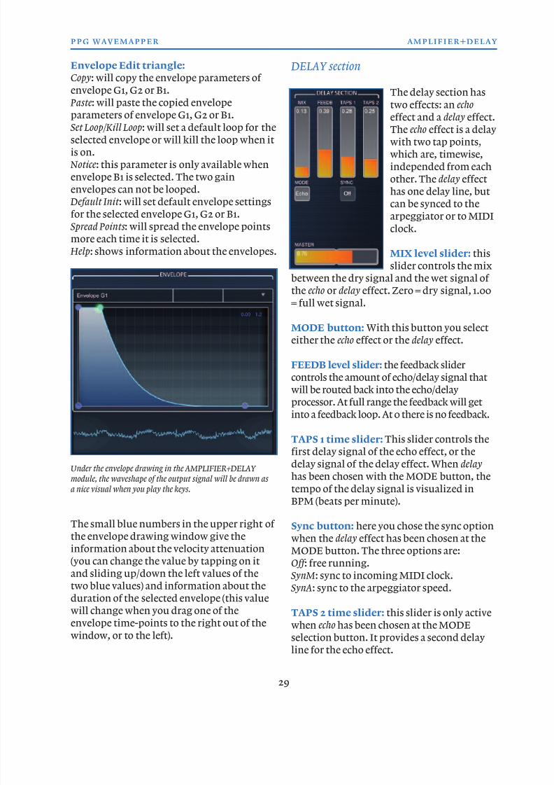
Envelope Edit triangle:
Copy: will copy the envelope parameters of
envelope G1, G2 or B1.
Paste: will paste the copied envelope
parameters of envelope G1, G2 or B1.
Set Loop/Kill Loop: will set a default loop for theselected envelope or will kill the loop when it
is on.
Notice: this parameter is only available when
envelope B1 is selected. The two gain
envelopes can not be looped.
Default Init : will set default envelope settings
for the selected envelope G1, G2 or B1.
Spread Points : will spread the envelope points
more each time it is selected.
Help: shows information about the envelopes.
The small blue numbers in the upper right of
the envelope drawing window give the
information about the velocity attenuation
(you can change the value by tapping on it
and sliding up/down the left values of the
two blue values) and information about the
duration of the selected envelope (this value
will change when you drag one of the
envelope time-points to the right out of the
window, or to the left).
DELAY section
The delay section has
two effects: an echo
effect and a delay effect.
The echo effect is a delaywith two tap points,
which are, timewise,
independed from each
other. The delay effect
has one delay line, but
can be synced to the
arpeggiator or to MIDI
clock.
MIX level slider: thisslider controls the mix
between the dry signal and the wet signal of
the echo or delay effect. Zero = dry signal, 1.00
= full wet signal.
MODE button: With this button you select
either the echo effect or the delay effect.
FEEDB level slider: the feedback slider
controls the amount of echo/delay signal that
will be routed back into the echo/delay
processor. At full range the feedback will get
into a feedback loop. At 0 there is no feedback.
TAPS 1 time slider: This slider controls the
first delay signal of the echo effect, or the
delay signal of the delay effect. When delay
has been chosen with the MODE button, the
tempo of the delay signal is visualized in
BPM (beats per minute).
Sync button: here you chose the sync option
when the delay effect has been chosen at the
MODE button. The three options are:
Off : free running.
SynM: sync to incoming MIDI clock.
SynA: sync to the arpeggiator speed.
TAPS 2 time slider: this slider is only active
when echo has been chosen at the MODE
selection button. It provides a second delayline for the echo effect.
29
ppg wavemapper amplifier+delay
Under the envelope drawing in the AMPLIFIER+DELAY
module, the waveshape of the output signal will be drawn as
a nice visual when you play the keys.
8/13/2019 WaveMapper Manual 1.0
http://slidepdf.com/reader/full/wavemapper-manual-10 30/50
Notice: The echo effect is better suited for
creating reverb-like echoes while the delay
effect can be used to create rhythmical
patterns of the notes you play.
MASTER level slider: this slider controls
the master volume of the PPG WaveMapper
app. It will be saved per preset program. This
way you can easily set a normalized volume
for a set of programs, for instance necessairy
when playing live with the app.
30
ppg wavemapper amplifier+delay
PARAMETERS module, AMPLIFIER +DELAY sub module window.
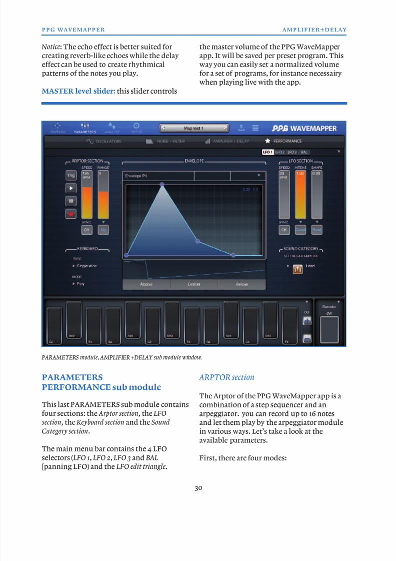
PARAMETERSPERFORMANCE sub module
This last PARAMETERS sub module contains
four sections: the Arptor section, the LFO
section, the Keyboard section and the Sound
Category section.
The main menu bar contains the 4 LFO
selectors ( LFO 1, LFO 2, LFO 3 and BAL[panning LFO) and the LFO edit triangle.
ARPTOR section
The Arptor of the PPG WaveMapper app is a
combination of a step sequencer and an
arpeggiator. you can record up to 16 notes
and let them play by the arpeggiator module
in various ways. Let’s take a look at the
available parameters.
First, there are four modes:
8/13/2019 WaveMapper Manual 1.0
http://slidepdf.com/reader/full/wavemapper-manual-10 31/50
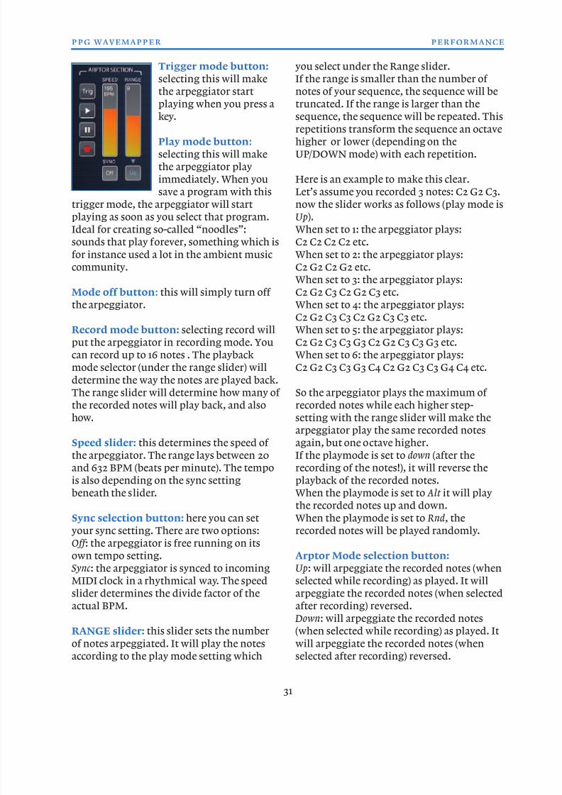
Trigger mode button:
selecting this will make
the arpeggiator start
playing when you press a
key.
Play mode button:
selecting this will make
the arpeggiator play
immediately. When you
save a program with this
trigger mode, the arpeggiator will start
playing as soon as you select that program.
Ideal for creating so-called “noodles”:
sounds that play forever, something which is
for instance used a lot in the ambient musiccommunity.
Mode off button: this will simply turn off
the arpeggiator.
Record mode button: selecting record will
put the arpeggiator in recording mode. You
can record up to 16 notes . The playback
mode selector (under the range slider) will
determine the way the notes are played back.
The range slider will determine how many of
the recorded notes will play back, and also
how.
Speed slider: this determines the speed of
the arpeggiator. The range lays between 20
and 632 BPM (beats per minute). The tempo
is also depending on the sync setting
beneath the slider.
Sync selection button: here you can setyour sync setting. There are two options:
Off : the arpeggiator is free running on its
own tempo setting.
Sync : the arpeggiator is synced to incoming
MIDI clock in a rhythmical way. The speed
slider determines the divide factor of the
actual BPM.
RANGE slider: this slider sets the number
of notes arpeggiated. It will play the notesaccording to the play mode setting which
you select under the Range slider.
If the range is smaller than the number of
notes of your sequence, the sequence will be
truncated. If the range is larger than the
sequence, the sequence will be repeated. This
repetitions transform the sequence an octavehigher or lower (depending on the
UP/DOWN mode) with each repetition.
Here is an example to make this clear.
Let’s assume you recorded 3 notes: C2 G2 C3.
now the slider works as follows (play mode is
Up).
When set to 1: the arpeggiator plays:
C2 C2 C2 C2 etc.
When set to 2: the arpeggiator plays:C2 G2 C2 G2 etc.
When set to 3: the arpeggiator plays:
C2 G2 C3 C2 G2 C3 etc.
When set to 4: the arpeggiator plays:
C2 G2 C3 C3 C2 G2 C3 C3 etc.
When set to 5: the arpeggiator plays:
C2 G2 C3 C3 G3 C2 G2 C3 C3 G3 etc.
When set to 6: the arpeggiator plays:
C2 G2 C3 C3 G3 C4 C2 G2 C3 C3 G4 C4 etc.
So the arpeggiator plays the maximum of
recorded notes while each higher step-
setting with the range slider will make the
arpeggiator play the same recorded notes
again, but one octave higher.
If the playmode is set to down (after the
recording of the notes!), it will reverse the
playback of the recorded notes.
When the playmode is set to Alt it will play
the recorded notes up and down.
When the playmode is set to Rnd, therecorded notes will be played randomly.
Arptor Mode selection button:
Up: will arpeggiate the recorded notes (when
selected while recording) as played. It will
arpeggiate the recorded notes (when selected
after recording) reversed.
Down: will arpeggiate the recorded notes
(when selected while recording) as played. It
will arpeggiate the recorded notes (whenselected after recording) reversed.
31
ppg wavemapper performance
8/13/2019 WaveMapper Manual 1.0
http://slidepdf.com/reader/full/wavemapper-manual-10 32/50
Alt : this will arpeggiate the recorded notes
up and down.
Rnd: this will arpeggiate the recorded notes
randomly.
Notice: the Arptor in record mode alwayesrecords what you play. The Mode parameter
modifies the playback function of the Arptor.
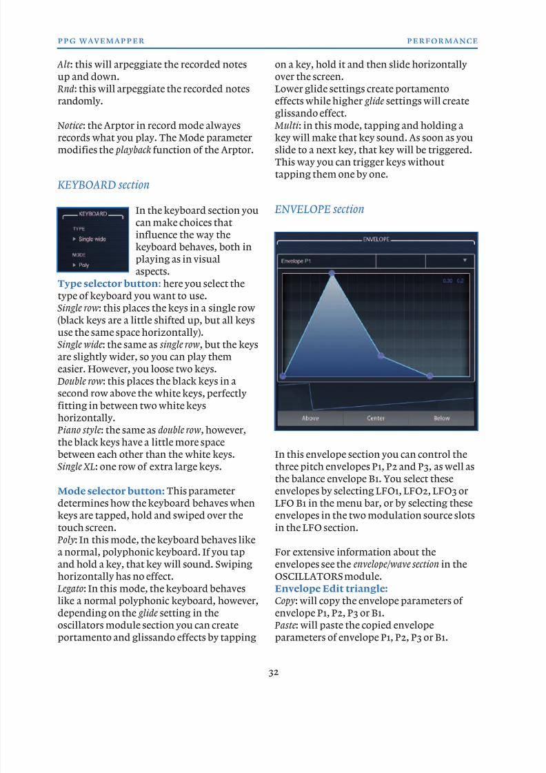
KEYBOARD section
In the keyboard section you
can make choices that
influence the way the
keyboard behaves, both inplaying as in visual
aspects.
Type selector button: here you select the
type of keyboard you want to use.
Single row: this places the keys in a single row
(black keys are a little shifted up, but all keys
use the same space horizontally).
Single wide: the same as single row, but the keys
are slightly wider, so you can play them
easier. However, you loose two keys.
Double row: this places the black keys in asecond row above the white keys, perfectly
fitting in between two white keys
horizontally.
Piano style: the same as double row, however,
the black keys have a little more space
between each other than the white keys.
Single XL: one row of extra large keys.
Mode selector button: This parameter
determines how the keyboard behaves whenkeys are tapped, hold and swiped over the
touch screen.
Poly: In this mode, the keyboard behaves like
a normal, polyphonic keyboard. If you tap
and hold a key, that key will sound. Swiping
horizontally has no effect.
Legato: In this mode, the keyboard behaves
like a normal polyphonic keyboard, however,
depending on the glide setting in the
oscillators module section you can createportamento and glissando effects by tapping
on a key, hold it and then slide horizontally
over the screen.
Lower glide settings create portamento
effects while higher glide settings will create
glissando effect.
Multi : in this mode, tapping and holding akey will make that key sound. As soon as you
slide to a next key, that key will be triggered.
This way you can trigger keys without
tapping them one by one.
ENVELOPE section
In this envelope section you can control the
three pitch envelopes P1, P2 and P3, as well as
the balance envelope B1. You select these
envelopes by selecting LFO1, LFO2, LFO3 or
LFO B1 in the menu bar, or by selecting theseenvelopes in the two modulation source slots
in the LFO section.
For extensive information about the
envelopes see the envelope/wave section in the
OSCILLATORS module.
Envelope Edit triangle:
Copy: will copy the envelope parameters of
envelope P1, P2, P3 or B1.
Paste: will paste the copied envelopeparameters of envelope P1, P2, P3 or B1.
32
ppg wavemapper performance
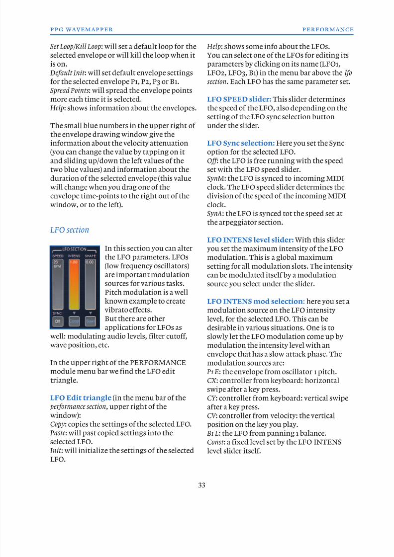
8/13/2019 WaveMapper Manual 1.0
http://slidepdf.com/reader/full/wavemapper-manual-10 33/50
Set Loop/Kill Loop: will set a default loop for the
selected envelope or will kill the loop when it
is on.
Default Init : will set default envelope settings
for the selected envelope P1, P2, P3 or B1.
Spread Points : will spread the envelope pointsmore each time it is selected.
Help: shows information about the envelopes.
The small blue numbers in the upper right of
the envelope drawing window give the
information about the velocity attenuation
(you can change the value by tapping on it
and sliding up/down the left values of the
two blue values) and information about the
duration of the selected envelope (this valuewill change when you drag one of the
envelope time-points to the right out of the
window, or to the left).
LFO section
In this section you can alter
the LFO parameters. LFOs
(low frequency oscillators)
are important modulationsources for various tasks.
Pitch modulation is a well
known example to create
vibrato effects.
But there are other
applications for LFOs as
well: modulating audio levels, filter cutoff,
wave position, etc.
In the upper right of the PERFORMANCEmodule menu bar we find the LFO edit
triangle.
LFO Edit triangle (in the menu bar of the
performance section, upper right of the
window):
Copy: copies the settings of the selected LFO.
Paste: will past copied settings into the
selected LFO.
Init : will initialize the settings of the selectedLFO.
Help: shows some info about the LFOs.
You can select one of the LFOs for editing its
parameters by clicking on its name (LFO1,
LFO2, LFO3, B1) in the menu bar above the lfo
section. Each LFO has the same parameter set.
LFO SPEED slider: This slider determines
the speed of the LFO, also depending on the
setting of the LFO sync selection button
under the slider.
LFO Sync selection: Here you set the Sync
option for the selected LFO.
Off : the LFO is free running with the speed
set with the LFO speed slider.
SynM: the LFO is synced to incoming MIDIclock. The LFO speed slider determines the
division of the speed of the incoming MIDI
clock.
SynA: the LFO is synced tot the speed set at
the arpeggiator section.
LFO INTENS level slider: With this slider
you set the maximum intensity of the LFO
modulation. This is a global maximum
setting for all modulation slots. The intensity
can be modulated itself by a modulation
source you select under the slider.
LFO INTENS mod selection: here you set a
modulation source on the LFO intensity
level, for the selected LFO. This can be
desirable in various situations. One is to
slowly let the LFO modulation come up by
modulation the intensity level with an
envelope that has a slow attack phase. The
modulation sources are: P1 E: the envelope from oscillator 1 pitch.
CX : controller from keyboard: horizontal
swipe after a key press.
CY : controller from keyboard: vertical swipe
after a key press.
CV : controller from velocity: the vertical
position on the key you play.
B1 L: the LFO from panning 1 balance.
Const : a fixed level set by the LFO INTENS
level slider itself.
33
ppg wavemapper performance
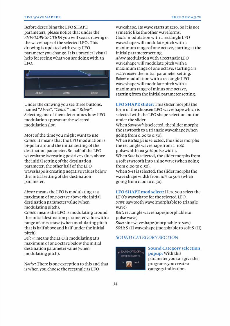
8/13/2019 WaveMapper Manual 1.0
http://slidepdf.com/reader/full/wavemapper-manual-10 34/50
Before describing the LFO SHAPE
parameters, please notice that under the
ENVELOPE SECTION you will see a drawing of
the waveshape of the selected LFO. This
drawing is updated with every LFO
parameter you change. It is a practical visualhelp for seeing what you are doing with an
LFO.
Under the drawing you see three buttons,named “ Above”, “Center ” and “ Below”.
Selecting one of them determines how LFO
modulation appears at the selected
modulation slot.
Most of the time you might want to use
Center . It means that the LFO modulation is
bi-polar around the initial setting of the
destination parameter. So half of the LFO
waveshape is creating positive values above
the initial setting of the destination
parameter, the other half of the LFO
waveshape is creating negative values below
the initial setting of the destination
parameter.
Above: means the LFO is modulating at a
maximum of one octave above the initial
destination parameter value (when
modulating pitch).
Center : means the LFO is modulating aroundthe initial destination parameter value with a
range of one octave (when modulating pitch
that is half above and half under the initial
pitch).
Below: means the LFO is modulating at a
maximum of one octave below the initial
destination parameter value (when
modulating pitch).
Notice: There is one exception to this and thatis when you choose the rectangle as LFO
waveshape. Its wave starts at zero. So it is not
symetric like the other waveforms.
Center modulation with a rectangle LFO
waveshape will modulate pitch with a
maximum range of one octave, starting at the
initial parameter setting. Above modulation with a rectangle LFO
waveshape will modulate pitch with a
maximum range of one octave, starting one
octave above the initial parameter setting.
Below modulation with a rectangle LFO
waveshape will modulate pitch with a
maximum range of minus one octave,
starting from the initial parameter setting.
LFO SHAPE slider: This slider morphs theform of the choosen LFO waveshape which is
selected with the LFO shape selection button
under the slider.
When Sawtooth is selected, the slider morphs
the sawtooth to a triangle waveshape (when
going from 0.00 to 0.50).
When Rectangle is selected, the slider morphs
the rectangle waveshape from a 10%
pulsewidth toa 50% pulse width.
When Sine is selected, the slider morphs from
a soft sawtooth into a sine wave (when going
from 0.00 to 0.50).
When S+H is selected, the slider morphs the
wave shape width from 10% to 50% (when
going from 0.00 to 0.50).
LFO SHAPE mod select: Here you select the
LFO’s waveshape for the selected LFO.
Sawt : sawtooth wave (morphable to triangle
wave)
Rect : rectangle waveshape (morphable topulse wave)
Sine: sine waveshape (morphable to saw)
S&H : S+H waveshape (morphable to soft S+H)
SOUND CATEGORY SECTION
Sound Category selection
popup: With this
parameter you can give the
programs you create acategory indication.
34
ppg wavemapper performance
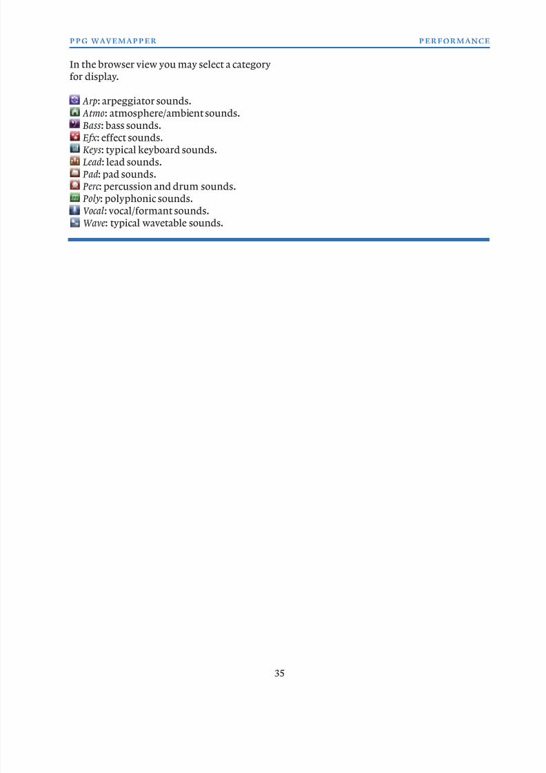
8/13/2019 WaveMapper Manual 1.0
http://slidepdf.com/reader/full/wavemapper-manual-10 35/50
In the browser view you may select a category
for display.
Arp: arpeggiator sounds.
Atmo: atmosphere/ambient sounds.
Bass : bass sounds. Efx : effect sounds.
Keys : typical keyboard sounds.
Lead: lead sounds.
Pad: pad sounds.
Perc : percussion and drum sounds.
Poly: polyphonic sounds.
Vocal: vocal/formant sounds.
Wave: typical wavetable sounds.
35
ppg wavemapper performance
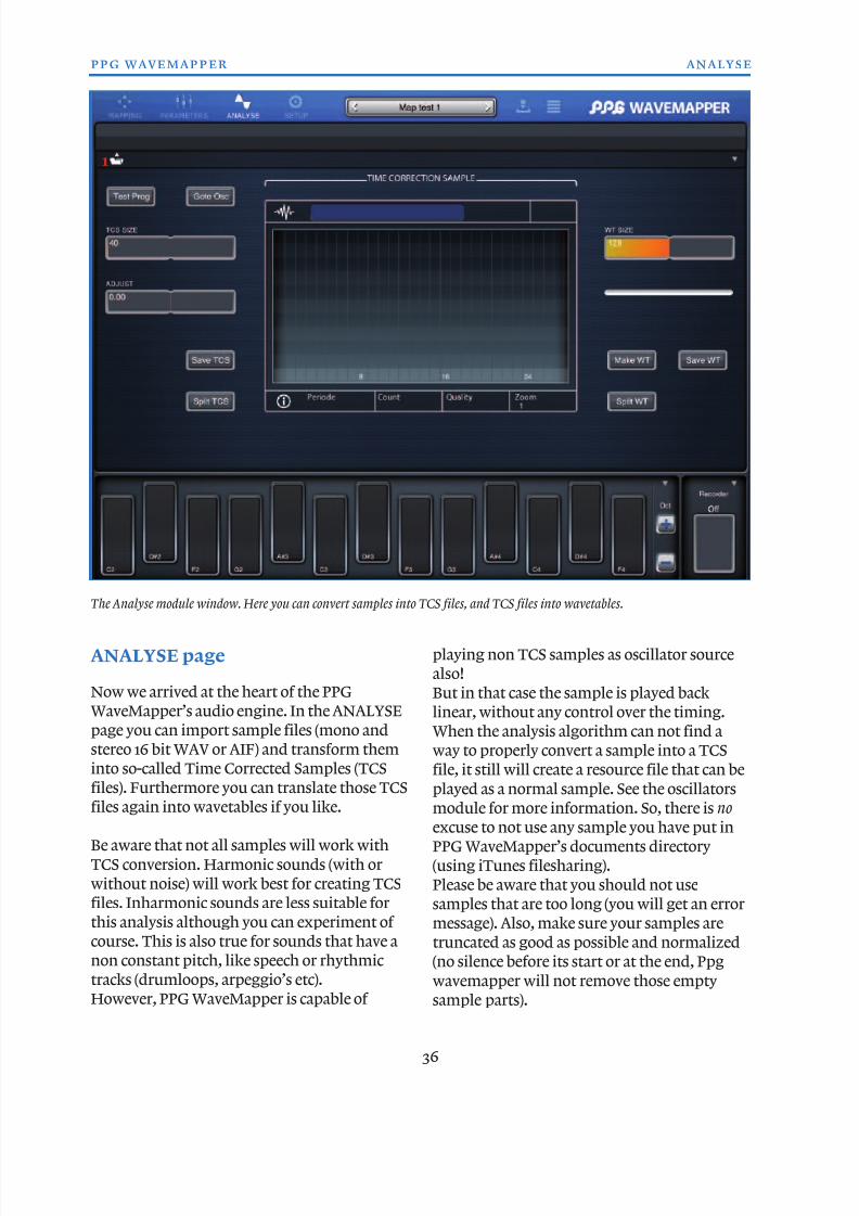
8/13/2019 WaveMapper Manual 1.0
http://slidepdf.com/reader/full/wavemapper-manual-10 36/50
ANALYSE page
Now we arrived at the heart of the PPG
WaveMapper’s audio engine. In the ANALYSE
page you can import sample files (mono and
stereo 16 bit WAV or AIF) and transform them
into so-called Time Corrected Samples (TCS
files). Furthermore you can translate those TCSfiles again into wavetables if you like.
Be aware that not all samples will work with
TCS conversion. Harmonic sounds (with or
without noise) will work best for creating TCS
files. Inharmonic sounds are less suitable for
this analysis although you can experiment of
course. This is also true for sounds that have a
non constant pitch, like speech or rhythmic
tracks (drumloops, arpeggio’s etc).
However, PPG WaveMapper is capable of
playing non TCS samples as oscillator source
also!
But in that case the sample is played back
linear, without any control over the timing.
When the analysis algorithm can not find a
way to properly convert a sample into a TCS
file, it still will create a resource file that can be
played as a normal sample. See the oscillatorsmodule for more information. So, there is no
excuse to not use any sample you have put in
PPG WaveMapper’s documents directory
(using iTunes filesharing).
Please be aware that you should not use
samples that are too long (you will get an error
message). Also, make sure your samples are
truncated as good as possible and normalized
(no silence before its start or at the end, Ppg
wavemapper will not remove those empty
sample parts).
36
ppg wavemapper analyse
The Analyse module window. Here you can convert samples into TCS files, and TCS files into wavetables.
1
8/13/2019 WaveMapper Manual 1.0
http://slidepdf.com/reader/full/wavemapper-manual-10 37/50
When you are in the ANALYSE page, it might
be best to start with a special test program to
hear how your samples translate into TCS
files. The test program has a looping wave
envelope set for oscillator 1 (to which the new
TCS file will be assigned).However, you may use any program to try out
the TCS files. If you do not use the test
program, the last program selected before
you switched to the ANALYSE page, will be
the program used. The newly created TCS file
will be assigned to oscillator 1 of that
program.
First of all, you need to copy one or more
samples into the document folder of the PPGWaveMapper app. You do that in iTunes on
your desktop or laptop computer.
Then those samples will appear under the
folder icon in the menu bar of the ANALYSE
page.
Then you might want to choose first which
program to use to play the TCS file: that could
be the program you had selected before you
switched to the ANALYSE page (do nothing)
or it could be the special test program: if so
press Test Prog first. You will then use a
program with a looped wave envelope for
oscillator 1 to which the TCS file will be
assigned.
After that, tap on the folder icon in the menu
bar and select the sample of your choice. Now
the audio engine will analyse the sample and
create a TCS file for you which you can
directly play on the keyboard (or not, but
then it will create a special TCS file that can beused as a normal sample for the oscillators).
Now let’s take a closer look at all the available
parameters to see what else you can do with
the TCS file.
Sample selection folder (upper left in the
ANALYSE page’s menu bar, label 1): as said
before, here you select the sample of your
choice for TCS conversion. Selecting a samplewill immediately start the TCS conversion.
Test Prog button: pressing this button will
initialize the program that will play the TCS
file. The test program uses one oscillator and
has a wave envelope in loop mode assigned, so
you can judge the result of the TCS
conversion. Press this before analysing thesample.
TCS size slider: With this slider you can make
the TCS file smaller by decreasing the number
of periods the sound file has. It would be good
practice to always use this slider to see if you
could decrease its size. Remember that the
iPad has limited memory so the shorter the
oscillator resources the better it is. Sometimes,
decreasing the number of periods with thisslider can also solve unwanted artifacts from
the TCS conversion. When adjusting the slider
you can still play the keyboard and hear
directly the results of your actions.
Adjust slider: this slider helps in correcting
the pitch of a TCS file, which might be “off”
for instance when noise is in the original
sample, or by a little pitch shifting in the
original sample. This can make the TCS file
detuned, specially when the resource file is
looped. Again, also this slider updates the file
directly so you can hear the results
immediately when playing the keyboard
while adjusting.
In the middle of the window you see a Time
Correction Sample section. Here, the TCS wave is
visualized in the grid-window plus some
information about the just created TCS file
that is shown under the drawing window: thenumber of periods (for a TCS file), the number
of waves (for a wavetable), the quality (how
well the original sample could be analyzed by
the TCS algorithm) and finally the zoom
factor (which may be changed by tapping on it
and selecting your choice).
Above the view window you can change the
name for the newly created TCS file.
Save TCS button: After translating a sampleinto a TCS file you might want to save it.
37
ppg wavemapper analyse
8/13/2019 WaveMapper Manual 1.0
http://slidepdf.com/reader/full/wavemapper-manual-10 38/50
Pressing this button will save the TCS file in
the PPG WaveMapper documents folder. It
will be named sample.c.wts (where “sample”
stands for the name of your original audio
file) when you look at it in the iTunes PPG
WaveMapper documents folder. In theoscillator resource selection popup menu it
will appear as sample.c.
Split TCS button: this is a special feature you
can assign to a TCS file. It will split the TCS
file into two different files with different
spectral contents:
sample.cl.wts which contains the low spectral
content of the original TCS file.
sample.ch.wts which contains the highspectral content of the original TCS file.
You could use these three TCS files for
instance in a three oscillator setup to have a
better level control of the spectral content of
the TCS file. But you are of course free to
experiment with just one of them!
When using Split TCS the sample.ch file will
become the oscillator 1 resource for the
selected program.
To the right of the TCS wave drawing window
you will find the parameters with which you
can translate a TCS file into a wavetable, or
split an existing wavetable into three
wavetable files with various spectral content.
WT Size slider: with this slider you set the
number of wavetable waves that should be
used for the translated wavetable. the simpler
the content of the wavetable, the less waves
should be used. More complex wavetablescould use the maximum of 256 waves.
Make WT button: pressing this button will
start the conversion of the TCS file into a
wavetable. The progress bar above it will
indicate the progress of the conversion.
When that process is finished you can play
the wavetable directly with the keyboard(again, the newly created wavetable will be
assigned as oscillator 1 resource of the
selected program).
Save WT button: this will save the
wavetable or split wavetable (see below) into
the PPG WaveMapper’s document folder, and
will become available in the resource popup
menu in the oscillator section.
Split WT button: this will split the
wavetable into three wavetable files, again
with different spectral content.
wavetable.l.wts which contains the low
spectral content of the original wavetable.
wavetable.h.wts which contains the high
spectral content of the original wavetable.
After splitting a wavetable the wavetable.h
file (the one with the high spectral content)
will be the selected oscillator resource for the
selected program.
ANALYSE page edit triangle
Expanding : when you want to split a existing
TCS or wavetable file at a later time, you can
do so by first selecting the program with the
TCS file or wavetable assigned to oscillator 1
you want to expand. Then select Expanding in
the popup menu when tapping the edit
triangle (upper right corner of the menu bar).
Help: this shows additional informationabout the Analyses module.
38
ppg wavemapper analyse
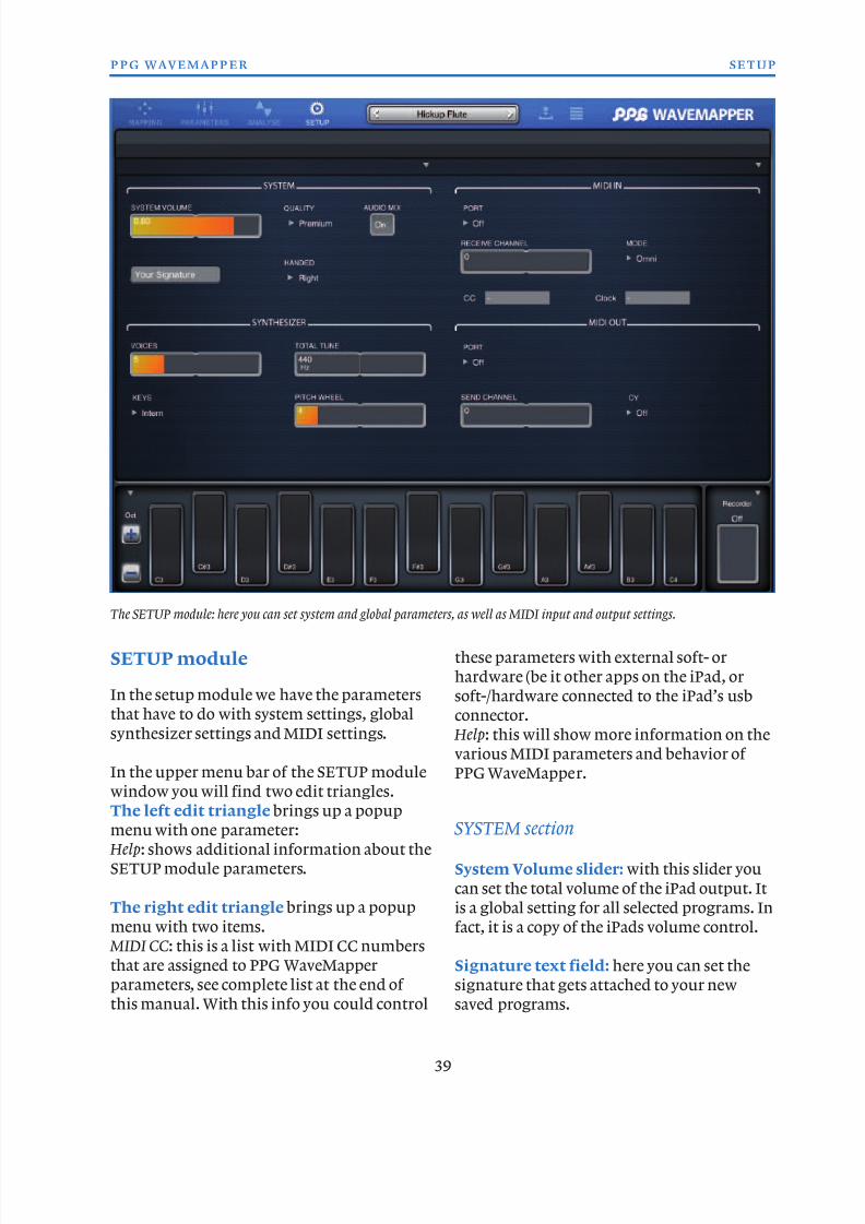
8/13/2019 WaveMapper Manual 1.0
http://slidepdf.com/reader/full/wavemapper-manual-10 39/50
SETUP module
In the setup module we have the parameters
that have to do with system settings, global
synthesizer settings and MIDI settings.
In the upper menu bar of the SETUP module
window you will find two edit triangles.The left edit triangle brings up a popup
menu with one parameter:
Help: shows additional information about the
SETUP module parameters.
The right edit triangle brings up a popup
menu with two items.
MIDI CC: this is a list with MIDI CC numbers
that are assigned to PPG WaveMapper
parameters, see complete list at the end of
this manual. With this info you could control
these parameters with external soft- or
hardware (be it other apps on the iPad, or
soft-/hardware connected to the iPad’s usb
connector.
Help: this will show more information on the
various MIDI parameters and behavior of
PPG WaveMapper.
SYSTEM section
System Volume slider: with this slider you
can set the total volume of the iPad output. It
is a global setting for all selected programs. In
fact, it is a copy of the iPads volume control.
Signature text field: here you can set the
signature that gets attached to your new
saved programs.
39
ppg wavemapper setup
The SETUP module: here you can set system and global parameters, as well as MIDI input and output settings.
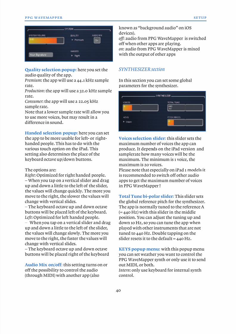
8/13/2019 WaveMapper Manual 1.0
http://slidepdf.com/reader/full/wavemapper-manual-10 40/50
Quality selection popup: here you set the
audio quality of the app.
Premium: the app will use a 44.1 kHz sample
rate.
Production: the app will use a 32.0 kHz sample
rate.
Consumer : the app will use a 22.05 kHz
sample rate.Note that a lower sample rate will allow you
to use more voices, but may result in a
difference in sound.
Handed selection popup: here you can set
the app to be more usable for left- or right-
handed people. This has to do with the
various touch option on the iPad. This
setting also determines the place of the
keyboard octave up/down buttons.
The options are:
Right : Optimized for right handed people.
– When you tap on a vertical slider and drag
up and down a little to the left of the slider,
the values will change quickly. The more you
move to the right, the slower the values will
change with vertical slides.
– The keyboard octave up and down octave
buttons will be placed left of the keyboard.
Left : Optimized for left handed people.– When you tap on a vertical slider and drag
up and down a little to the left of the slider,
the values will change slowly. The more you
move to the right, the faster the values will
change with vertical slides.
– The keyboard octave up and down octave
buttons will be placed right of the keyboard
Audio Mix on/off : this setting turns on or
off the possibility to control the audio(through MIDI) with another app (also
known as “background audio” on iOS
devices).
off : audio from PPG WaveMapper is switched
off when other apps are playing.
on: audio from PPG WaveMapper is mixed
with the output of other apps
SYNTHESIZER section
In this section you can set some global
parameters for the synthesizer.
Voices selection slider: this slider sets the
maximum number of voices the app can
produce. It depends on the iPad version and
samplerate how many voices will be the
maximum. The minimum is 1 voice, the
maximum is 20 voices.Please note that especially on iPad 1 models it
is recommended to switch off other audio
apps to get the maximum number of voices
in PPG WaveMapper !
Total Tune bi-polar slider: This slider sets
the global reference pitch for the synthesizer.
The app is normally tuned to the reference A
(= 440 Hz) with this slider in the middle
position. You can adjust the tuning up anddown 10 Hz, so you can tune the app when
played with other instruments that are not
tuned to 440 Hz. Double tapping on the
slider resets it to the default = 440 Hz.
KEYS popup menu: with this popup menu
you can set weather you want to control the
PPG WaveMapper synth or only use it to send
out MIDI, or both.
Intern: only use keyboard for internal synthcontrol.
40
ppg wavemapper setup
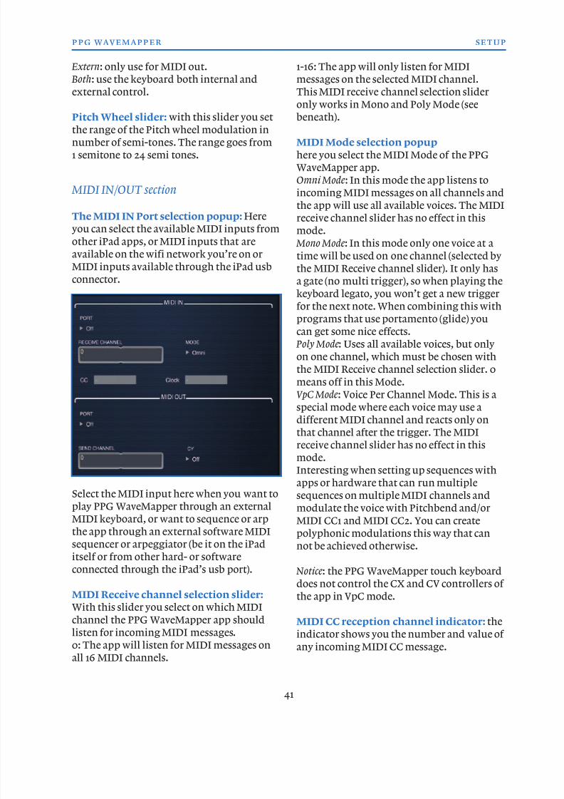
8/13/2019 WaveMapper Manual 1.0
http://slidepdf.com/reader/full/wavemapper-manual-10 41/50
Extern: only use for MIDI out.
Both: use the keyboard both internal and
external control.
Pitch Wheel slider: with this slider you set
the range of the Pitch wheel modulation innumber of semi-tones. The range goes from
1 semitone to 24 semi tones.
MIDI IN/OUT section
The MIDI IN Port selection popup: Here
you can select the available MIDI inputs from
other iPad apps, or MIDI inputs that are
available on the wifi network you’re on or
MIDI inputs available through the iPad usb
connector.
Select the MIDI input here when you want to
play PPG WaveMapper through an external
MIDI keyboard, or want to sequence or arpthe app through an external software MIDI
sequencer or arpeggiator (be it on the iPad
itself or from other hard- or software
connected through the iPad’s usb port).
MIDI Receive channel selection slider:
With this slider you select on which MIDI
channel the PPG WaveMapper app should
listen for incoming MIDI messages.
0: The app will listen for MIDI messages on
all 16 MIDI channels.
1-16: The app will only listen for MIDI
messages on the selected MIDI channel.
This MIDI receive channel selection slider
only works in Mono and Poly Mode (see
beneath).
MIDI Mode selection popup
here you select the MIDI Mode of the PPG
WaveMapper app.
Omni Mode: In this mode the app listens to
incoming MIDI messages on all channels and
the app will use all available voices. The MIDI
receive channel slider has no effect in this
mode.
Mono Mode: In this mode only one voice at a
time will be used on one channel (selected bythe MIDI Receive channel slider). It only has
a gate (no multi trigger), so when playing the
keyboard legato, you won’t get a new trigger
for the next note. When combining this with
programs that use portamento (glide) you
can get some nice effects.
Poly Mode: Uses all available voices, but only
on one channel, which must be chosen with
the MIDI Receive channel selection slider. 0
means off in this Mode.
VpC Mode: Voice Per Channel Mode. This is a
special mode where each voice may use a
different MIDI channel and reacts only on
that channel after the trigger. The MIDI
receive channel slider has no effect in this
mode.
Interesting when setting up sequences with
apps or hardware that can run multiple
sequences on multiple MIDI channels and
modulate the voice with Pitchbend and/or
MIDI CC1 and MIDI CC2. You can createpolyphonic modulations this way that can
not be achieved otherwise.
Notice: the PPG WaveMapper touch keyboard
does not control the CX and CV controllers of
the app in VpC mode.
MIDI CC reception channel indicator: the
indicator shows you the number and value of
any incoming MIDI CC message.
41
ppg wavemapper setup
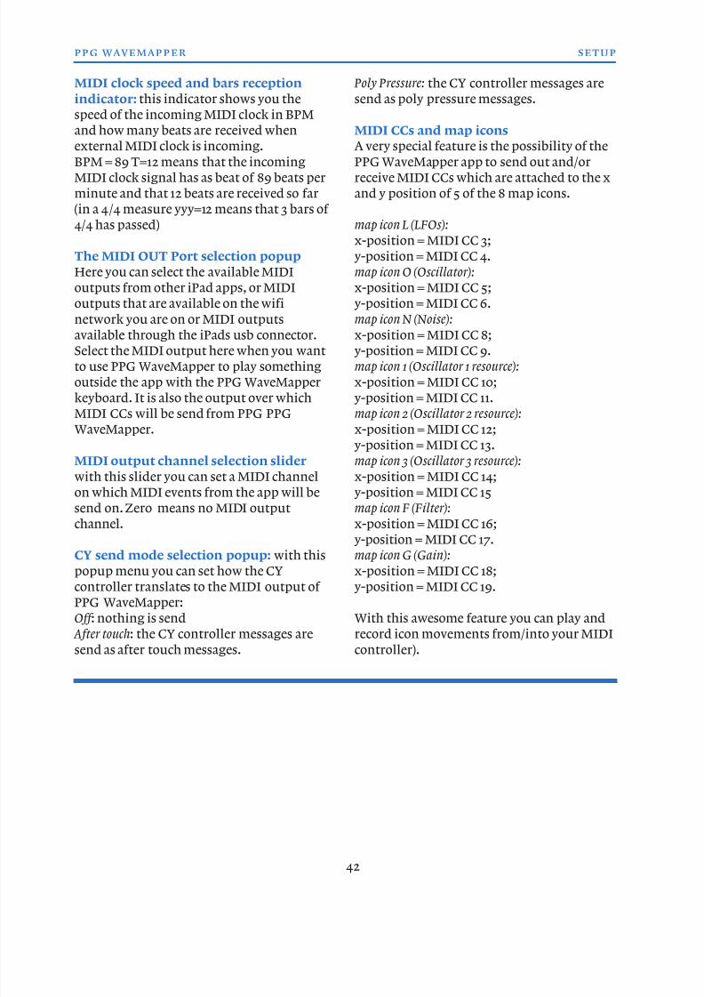
8/13/2019 WaveMapper Manual 1.0
http://slidepdf.com/reader/full/wavemapper-manual-10 42/50
MIDI clock speed and bars reception
indicator: this indicator shows you the
speed of the incoming MIDI clock in BPM
and how many beats are received when
external MIDI clock is incoming.
BPM = 89 T=12 means that the incomingMIDI clock signal has as beat of 89 beats per
minute and that 12 beats are received so far
(in a 4/4 measure yyy=12 means that 3 bars of
4/4 has passed)
The MIDI OUT Port selection popup
Here you can select the available MIDI
outputs from other iPad apps, or MIDI
outputs that are available on the wifi
network you are on or MIDI outputsavailable through the iPads usb connector.
Select the MIDI output here when you want
to use PPG WaveMapper to play something
outside the app with the PPG WaveMapper
keyboard. It is also the output over which
MIDI CCs will be send from PPG PPG
WaveMapper.
MIDI output channel selection slider
with this slider you can set a MIDI channel
on which MIDI events from the app will be
send on. Zero means no MIDI output
channel.
CY send mode selection popup: with this
popup menu you can set how the CY
controller translates to the MIDI output of
PPG WaveMapper:
Off : nothing is send
After touch: the CY controller messages are
send as after touch messages.
Poly Pressure: the CY controller messages are
send as poly pressure messages.
MIDI CCs and map icons
A very special feature is the possibility of the
PPG WaveMapper app to send out and/orreceive MIDI CCs which are attached to the x
and y position of 5 of the 8 map icons.
map icon L (LFOs):
x-position = MIDI CC 3;
y-position = MIDI CC 4.
map icon O (Oscillator):
x-position = MIDI CC 5;
y-position = MIDI CC 6.
map icon N (Noise):x-position = MIDI CC 8;
y-position = MIDI CC 9.
map icon 1 (Oscillator 1 resource):
x-position = MIDI CC 10;
y-position = MIDI CC 11.
map icon 2 (Oscillator 2 resource):
x-position = MIDI CC 12;
y-position = MIDI CC 13.
map icon 3 (Oscillator 3 resource):
x-position = MIDI CC 14;
y-position = MIDI CC 15
map icon F (Filter):
x-position = MIDI CC 16;
y-position = MIDI CC 17.
map icon G (Gain):
x-position = MIDI CC 18;
y-position = MIDI CC 19.
With this awesome feature you can play and
record icon movements from/into your MIDI
controller).
42
ppg wavemapper setup
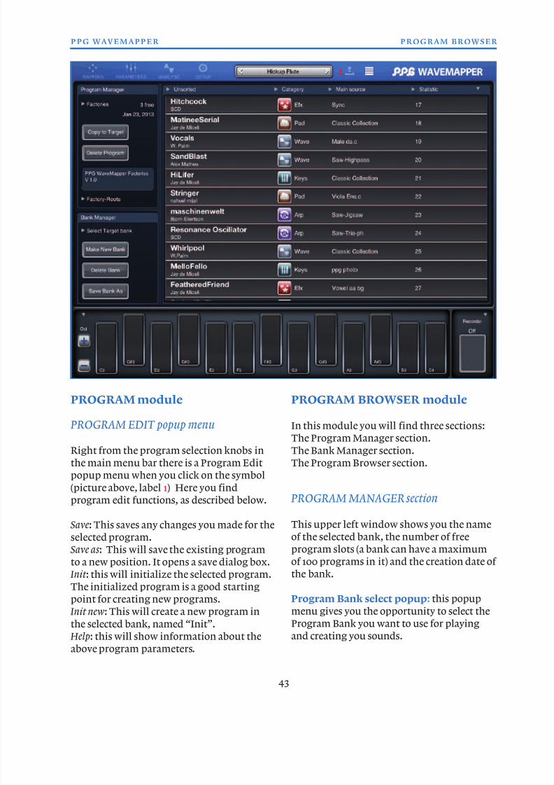
8/13/2019 WaveMapper Manual 1.0
http://slidepdf.com/reader/full/wavemapper-manual-10 43/50
PROGRAM module
PROGRAM EDIT popup menu
Right from the program selection knobs in
the main menu bar there is a Program Edit
popup menu when you click on the symbol
(picture above, label 1) Here you find
program edit functions, as described below.
Save: This saves any changes you made for the
selected program.
Save as : This will save the existing program
to a new position. It opens a save dialog box.
Init : this will initialize the selected program.
The initialized program is a good starting
point for creating new programs.
Init new: This will create a new program in
the selected bank, named “Init”.
Help: this will show information about theabove program parameters.
PROGRAM BROWSER module
In this module you will find three sections:
The Program Manager section.
The Bank Manager section.
The Program Browser section.
PROGRAM MANAGER section
This upper left window shows you the name
of the selected bank, the number of free
program slots (a bank can have a maximum
of 100 programs in it) and the creation date of
the bank.
Program Bank select popup: this popup
menu gives you the opportunity to select the
Program Bank you want to use for playing
and creating you sounds.
43
ppg wavemapper program browser
1
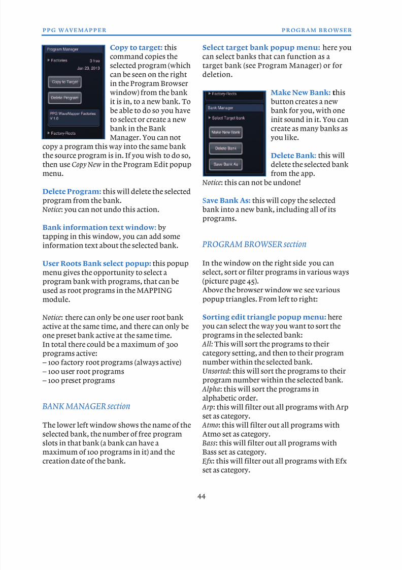
8/13/2019 WaveMapper Manual 1.0
http://slidepdf.com/reader/full/wavemapper-manual-10 44/50
Copy to target: this
command copies the
selected program (which
can be seen on the right
in the Program Browser
window) from the bankit is in, to a new bank. To
be able to do so you have
to select or create a new
bank in the Bank
Manager. You can not
copy a program this way into the same bank
the source program is in. If you wish to do so,
then use Copy New in the Program Edit popup
menu.
Delete Program: this will delete the selected
program from the bank.
Notice: you can not undo this action.
Bank information text window: by
tapping in this window, you can add some
information text about the selected bank.
User Roots Bank select popup: this popup
menu gives the opportunity to select a
program bank with programs, that can be
used as root programs in the MAPPING
module.
Notice: there can only be one user root bank
active at the same time, and there can only be
one preset bank active at the same time.
In total there could be a maximum of 300
programs active:
– 100 factory root programs (always active)
– 100 user root programs– 100 preset programs
BANK MANAGER section
The lower left window shows the name of the
selected bank, the number of free program
slots in that bank (a bank can have a
maximum of 100 programs in it) and the
creation date of the bank.
Select target bank popup menu: here you
can select banks that can function as a
target bank (see Program Manager) or for
deletion.
Make New Bank: thisbutton creates a new
bank for you, with one
init sound in it. You can
create as many banks as
you like.
Delete Bank: this will
delete the selected bank
from the app.
Notice: this can not be undone!
Save Bank As: this will copy the selected
bank into a new bank, including all of its
programs.
PROGRAM BROWSER section
In the window on the right side you can
select, sort or filter programs in various ways
(picture page 45).Above the browser window we see various
popup triangles. From left to right:
Sorting edit triangle popup menu: here
you can select the way you want to sort the
programs in the selected bank:
All: This will sort the programs to their
category setting, and then to their program
number within the selected bank.
Unsorted: this will sort the programs to theirprogram number within the selected bank.
Alpha: this will sort the programs in
alphabetic order.
Arp: this will filter out all programs with Arp
set as category.
Atmo: this will filter out all programs with
Atmo set as category.
Bass : this will filter out all programs with
Bass set as category.
Efx : this will filter out all programs with Efxset as category.
44
ppg wavemapper program browser
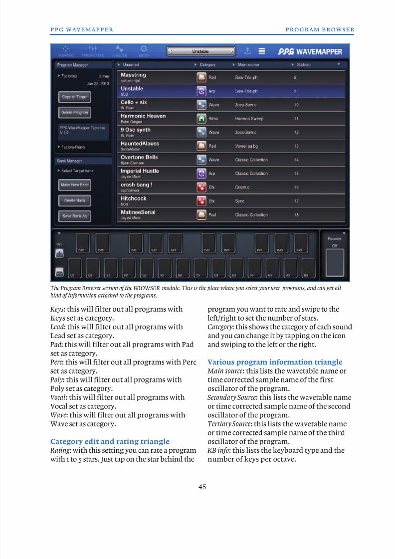
8/13/2019 WaveMapper Manual 1.0
http://slidepdf.com/reader/full/wavemapper-manual-10 45/50
Keys : this will filter out all programs with
Keys set as category.
Lead: this will filter out all programs with
Lead set as category.
Pad: this will filter out all programs with Pad
set as category.
Perc : this will filter out all programs with Percset as category.
Poly: this will filter out all programs with
Poly set as category.
Vocal: this will filter out all programs with
Vocal set as category.
Wave: this will filter out all programs with
Wave set as category.
Category edit and rating triangle
Rating : with this setting you can rate a program
with 1 to 5 stars. Just tap on the star behind the
program you want to rate and swipe to the
left/right to set the number of stars.
Category: this shows the category of each sound
and you can change it by tapping on the icon
and swiping to the left or the right.
Various program information triangle Main source: this lists the wavetable name or
time corrected sample name of the first
oscillator of the program.
Secondary Source: this lists the wavetable name
or time corrected sample name of the second
oscillator of the program.
Tertiary Source: this lists the wavetable name
or time corrected sample name of the third
oscillator of the program.
KB info: this lists the keyboard type and the
number of keys per octave.
45
ppg wavemapper program browser
The Program Browser section of the BROWSER module. This is the place where you select your user programs, and can get all
kind of information attached to the programs.
8/13/2019 WaveMapper Manual 1.0
http://slidepdf.com/reader/full/wavemapper-manual-10 46/50
KEYBOARD
The keyboard in the lower section of the screen
will always be visible, no matter what module,
page or section you are viewing. This way you
can always play your (edited) sounds, no
matter what.
They keyboard is customizable in various
ways.
To the right or left of the keyboard (depending
on the “Handed” setting in the SETUP
module) there are two buttons to shift the
keyboard up and down per octave. The total
up/down range of the keyboard is 5 octaves
this way. You can make that range even wider
by using the oscillators octave settings in the
OSCILLATORS module.Above these octave up/down buttons you will
find the keyboard edit triangle with some
more keyboard controls.
+/- octave buttons: these two button will shift
up/down the keyboard 1 octave each time you
tap on them.
keyboard edit triangle (label 1 in the upper
picture next page): here you will find some edit
options for the keyboard.
Reset : Will reset the keyboard to 12 semitones.
Copy: will copy the keyboard settings to the
clipboard.
Paste: will past the copied keyboard settings
into the selected preset program.
Modes: this is a shortcut to the KEYBOARD
section in the PERFORMANCE sub module.
There you can edit the keyboard type, modeand scale to taste.
Extend/Reduce stage: this is a nice feature for live
performance. It toggles between the reduced
and extended keys (vertical length), see lower
picture on page 47. This will obviously only
work with a single row keyboard view. The CY
and CV controller will be extended vertically
as well when chosen. You can not save this
setting.
Notice: a shortcut for the Extend/Reduce
function is tapping on the lower half of the
Recorder field (lower picture page 47, label 2)
Edit : when selecting this setting, each key you
touch on the keyboard will disappear. This way
you can create custom keyboard scales which
can be saved per program.
Help: extra information about the keyboard.
Notice: The keyboard settings here work
together with the KEYBOARD section (see
page 32).
Envelopes : this lists the number of used
envelopes in the program.
Arptor : this lists info for the Arptor setting
of the program.
Program date/update and programnumber lising popup triangle
Created: this will show the creation date of
each program.
Updated: this will show the latest
modification date of each program.
Statistic : this will list the program number
of each program.
Bank edit triangle
Export : this will let you export the selected
bank with all its programs from the app
through email. After selecting Export you
will be asked if you would like to include the
user resources you might have added to the
factory ones. After that, an email will be
composed with the backup-data which youthen can send to the email address of your
choice. This is a very convenient way to
make backups of your sounds, or to share
them with other users.
Reset Presets : this command will reset all
factory presets to its original state.
Notice: this can not be undone! Make a copy
Help: this shows more info on the Program
Browser module.
46
ppg wavemapper program browser
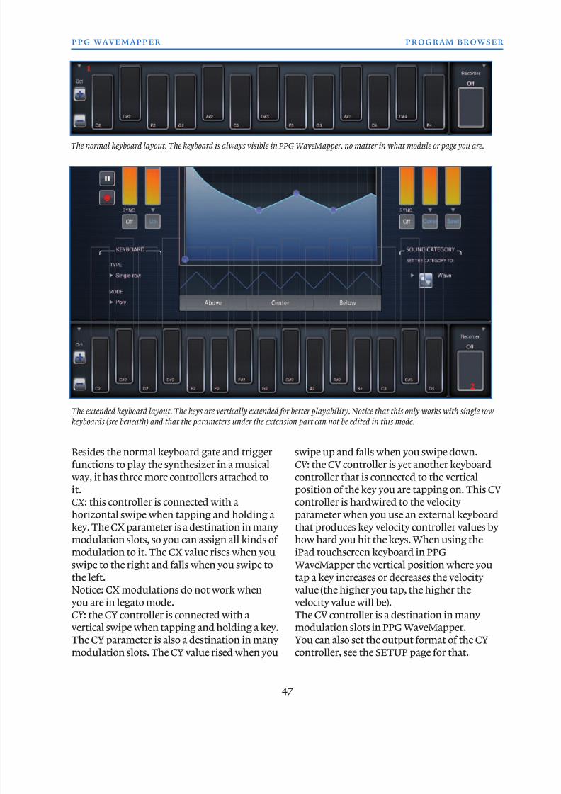
8/13/2019 WaveMapper Manual 1.0
http://slidepdf.com/reader/full/wavemapper-manual-10 47/50
47
ppg wavemapper program browser
Besides the normal keyboard gate and trigger
functions to play the synthesizer in a musical
way, it has three more controllers attached to
it.
CX : this controller is connected with a
horizontal swipe when tapping and holding akey. The CX parameter is a destination in many
modulation slots, so you can assign all kinds of
modulation to it. The CX value rises when you
swipe to the right and falls when you swipe to
the left.
Notice: CX modulations do not work when
you are in legato mode.
CY : the CY controller is connected with a
vertical swipe when tapping and holding a key.
The CY parameter is also a destination in many
modulation slots. The CY value rised when you
swipe up and falls when you swipe down.
CV : the CV controller is yet another keyboard
controller that is connected to the vertical
position of the key you are tapping on. This CV
controller is hardwired to the velocity
parameter when you use an external keyboardthat produces key velocity controller values by
how hard you hit the keys. When using the
iPad touchscreen keyboard in PPG
WaveMapper the vertical position where you
tap a key increases or decreases the velocity
value (the higher you tap, the higher the
velocity value will be).
The CV controller is a destination in many
modulation slots in PPG WaveMapper.
You can also set the output format of the CY
controller, see the SETUP page for that.
1
The normal keyboard layout. The keyboard is always visible in PPG WaveMapper, no matter in what module or page you are.
The extended keyboard layout. The keys are vertically extended for better playability. Notice that this only works with single row
keyboards (see beneath) and that the parameters under the extension part can not be edited in this mode.
2
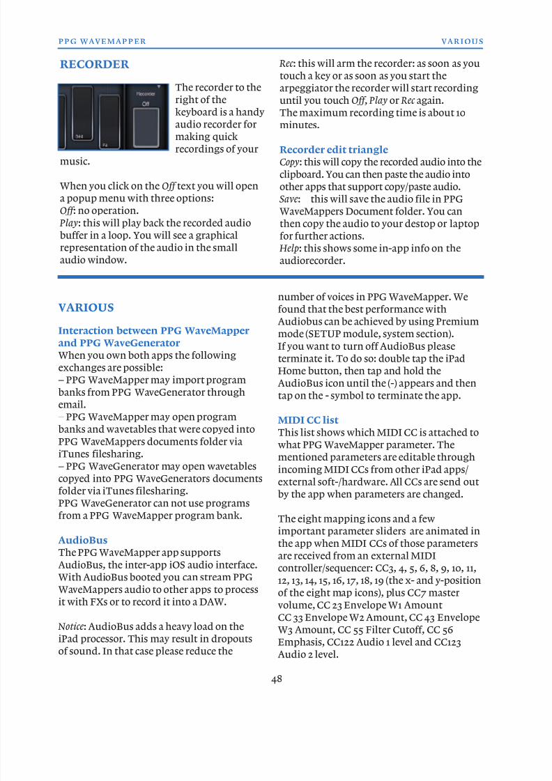
8/13/2019 WaveMapper Manual 1.0
http://slidepdf.com/reader/full/wavemapper-manual-10 48/50
VARIOUS
Interaction between PPG WaveMapper
and PPG WaveGenerator
When you own both apps the following
exchanges are possible:
– PPG WaveMapper may import programbanks from PPG WaveGenerator through
email.
– PPG WaveMapper may open program
banks and wavetables that were copyed into
PPG WaveMappers documents folder via
iTunes filesharing.
– PPG WaveGenerator may open wavetables
copyed into PPG WaveGenerators documents
folder via iTunes filesharing.
PPG WaveGenerator can not use programs
from a PPG WaveMapper program bank.
AudioBus
The PPG WaveMapper app supports
AudioBus, the inter-app iOS audio interface.
With AudioBus booted you can stream PPG
WaveMappers audio to other apps to process
it with FXs or to record it into a DAW.
Notice: AudioBus adds a heavy load on the
iPad processor. This may result in dropoutsof sound. In that case please reduce the
number of voices in PPG WaveMapper. We
found that the best performance with
Audiobus can be achieved by using Premium
mode (SETUP module, system section).
If you want to turn off AudioBus please
terminate it. To do so: double tap the iPad
Home button, then tap and hold the
AudioBus icon until the (-) appears and thentap on the - symbol to terminate the app.
MIDI CC list
This list shows which MIDI CC is attached to
what PPG WaveMapper parameter. The
mentioned parameters are editable through
incoming MIDI CCs from other iPad apps/
external soft-/hardware. All CCs are send out
by the app when parameters are changed.
The eight mapping icons and a few
important parameter sliders are animated in
the app when MIDI CCs of those parameters
are received from an external MIDI
controller/sequencer: CC3, 4, 5, 6, 8, 9, 10, 11,
12, 13, 14, 15, 16, 17, 18, 19 (the x- and y-position
of the eight map icons), plus CC7 master
volume, CC 23 Envelope W1 Amount
CC 33 Envelope W2 Amount, CC 43 Envelope
W3 Amount, CC 55 Filter Cutoff, CC 56
Emphasis, CC122 Audio 1 level and CC123
Audio 2 level.
48
ppg wavemapper various
RECORDER
The recorder to the
right of the
keyboard is a handy
audio recorder formaking quick
recordings of your
music.
When you click on the Off text you will open
a popup menu with three options:
Off : no operation.
Play: this will play back the recorded audio
buffer in a loop. You will see a graphical
representation of the audio in the small
audio window.
Rec : this will arm the recorder: as soon as you
touch a key or as soon as you start the
arpeggiator the recorder will start recording
until you touch Off , Play or Rec again.
The maximum recording time is about 10
minutes.
Recorder edit triangle
Copy: this will copy the recorded audio into the
clipboard. You can then paste the audio into
other apps that support copy/paste audio.
Save: this will save the audio file in PPG
WaveMappers Document folder. You can
then copy the audio to your destop or laptop
for further actions.
Help: this shows some in-app info on the
audiorecorder.
8/13/2019 WaveMapper Manual 1.0
http://slidepdf.com/reader/full/wavemapper-manual-10 49/50
Full MIDI CC list
CC 1 CY controller
CC 2 CX controller
CC 3 LFO Map Icon X
CC 4 LFO Map Icon Y
CC 5 Oscillator Map Icon XCC 6 Oscillator Map Icon Y
CC 7 Master Volume
CC 8 Noise Map Icon X
CC 9 Noise Map Icon Y
CC 10 Osc 1 Map Icon X
CC 11 Osc 1 Map Icon Y
CC 12 Osc 2 Map Icon Y
CC 13 Osc 2 Map Icon Y
CC 14 Osc 3 Map Icon X
CC 15 Osc 3 Map Icon YCC 16 Filter Map Icon X
CC 17 Filter Map Icon Y
CC 18 Gain Map Icon X
CC 19 Gain Map Icon Y
CC 20 Osc 1 Glide rate
CC 21 Osc 1 Pitch Mod 1 level
CC 22 Osc 1 Pitch Mod 2 level
CC 23 Osc 1 Pitch Envelope intensity level
CC 24 Osc 1 Wave Mod 1 level
CC 25 Osc 1 Wave Mod 2 level
CC 26 Osc 1 Wave Offset
CC 27 Osc 1 Wave Blending level
CC 28 Osc 1 Volume level
CC 29
CC 30 Osc 2 Glide rate
CC 31 Osc 2 Pitch Mod 1 level
CC 32 Osc 2 Pitch Mod 2 level
CC 33 Osc 2 Pitch Envelope intensity level
CC 34 Osc 2 Wave Mod 1 level
CC 35 Osc 2 Wave Mod 2 level
CC 36 Osc 2 Wave OffsetCC 37 Osc 2 Wave Blending level
CC 38 Osc 2 Volume level
CC 39
CC 40 Osc 3 Glide rate
CC 41 Osc 3 Pitch Mod 1 level
CC 42 Osc 3 Pitch Mod 2 level
CC 43 Osc 3 Pitch Envelope intensity level
CC 44 Osc 3 Wave Mod 1 level
CC 45 Osc 3 Wave Mod 2 level
CC 46 Osc 3 Wave OffsetCC 47 Osc 3 Wave Blending level
CC 48 Osc 3 Volume level
CC 49
CC 50 Noise1 Audio Gain level
CC 51 Noise1 Color
CC 52
CC 53CC 54
CC 55 Filter Cutoff
CC 56 Filter Emphasis
CC 57 Filter Modulation 1 Level
CC 58 Filter Modulation 2 Level
CC 59
CC 60
CC 61
CC 62
CC 63CC 64
CC 65
CC 66
CC 67
CC 68
CC 69
CC 70 LFO 1 Intensity
CC 71 LFO 1 Waveshape morph
CC 72 LFO 1 Speed
CC 73 LFO 2 Intensity
CC 74 LFO 2 Waveshape morph
CC 75 LFO 2 Speed
CC 76 LFO 3 Intensity
CC 77 LFO 3 Waveshape morph
CC 78 LFO 3 Speed
CC 79 LFO 4 Intensity
CC 80 LFO 4 Waveshape morph
CC 81 LFO 4 Speed
CC 82
CC 83
CC 84CC 85
CC 86
CC 87
CC 88
CC 89
CC 90 Envelope 1 (wave osc 1) Attack
CC 91 Envelope 1 (wave osc 1) Decay
CC 92 Envelope 1 (wave osc 1) Sustain
CC 93 Envelope 1 (wave osc 1) Release
CC 94 Envelope 1 (wave osc 1) base levelCC 95 Envelope 1 (wave osc 1) peak level
49
ppg wavemapper various
8/13/2019 WaveMapper Manual 1.0
http://slidepdf.com/reader/full/wavemapper-manual-10 50/50
CC 96 Envelope 2 (gain audio 1) Attack
CC 97 Envelope 2 (gain audio 1) Decay
CC 98 Envelope 2 (gain audio 1) Sustain
CC 99 Envelope 2 (gain audio 1) Release
CC 100 Envelope 3 (filter) Attack
CC 101 Envelope 3 (filter) DecayCC 102 Envelope 3 (filter) Sustain
CC 103 Envelope 3 (filter) Release
CC 104 Envelope 3 (filter) base level
CC 105 Envelope 3 (filter) peak level
CC 106 Envelope 4 (wave osc 2) Attack
CC 107 Envelope 4 (wave osc 2) Decay
CC 108 Envelope 4 (wave osc 2) Sustain
CC 109 Envelope 4 (wave osc 2) Release
CC 110 Envelope 4 (wave osc 2) base level
CC 111 Envelope 4 (wave osc 2) peak level
CC 112 Envelope 5 (wave osc 3) Attack
CC 113 Envelope 5 (wave osc 3) Decay
CC 114 Envelope 5 (wave osc 3) Sustain
CC 115 Envelope 5 (wave osc 3) Release
CC 116 Envelope 5 (wave osc 3) base level
CC 117 Envelope 5 (wave osc 3) peak levelCC 118 Envelope 6 (noise 1) Attack
CC 119 Envelope 6 (noise 1) Decay
CC 120 Envelope 6 (noise 1) Sustain
CC 121 Envelope 6 (noise 1) Release
CC 122 Audio 1 gain level
CC 123 Audio 2 gain level
CC 124 Spread
CC 125 Gain Mod level
CC 126 Panning Mod level
CC 127 VCA 2 envelope gain level
ppg wavemapper various