Waveform Coder - University of California, Berkeleyee225b/sp14/lectures/waveform_codin… ·...
10
Waveform Coder PCl\1 Coding - . - - -- . --- -I I ~I A)OI1-LaJti;/",.? 1--7 ;1 .f.(n~n~) . very simple . typically requires over 5-6 bits/pixel for good quality . false contours for low-bit rate case
Transcript of Waveform Coder - University of California, Berkeleyee225b/sp14/lectures/waveform_codin… ·...

Waveform Coder
PCl\1 Coding-
. - - -- . ---
-II
~I A)OI1-LaJti;/",.? 1--7;1
.f.(n~n~)
. very simple
. typically requires over 5-6 bits/pixel for good quality
. false contours for low-bit rate case

Improvements of PCM (cont.)
2. RobeI1s~Pseudo-Noise Technique with Noise Reduction:Trlnsmltter
II
Uniform I +qUlntiur I +
+ 1 IIIIII
win,. n2) _.-- - - -~ ~ win,. n2)II
Noisereduction
- - -- ~----
~\\ Roberts' Pseudo-Noise Technique and HighpasslLowpa~s"/'F:ptering: / /.
, , [ r I. ., I . I
\ I 1/\ ~..,.I,.., /
\ f~-)\Oi$.2. ...
\ ...1=:, ~ k. ////
/
///
'''./~
/ """'"
./ '-'"
If there w.=re~~p(HighPass~wpass Filtering:. ~/ ~ F
/i-..'"'--.- .
Improvements of PCM
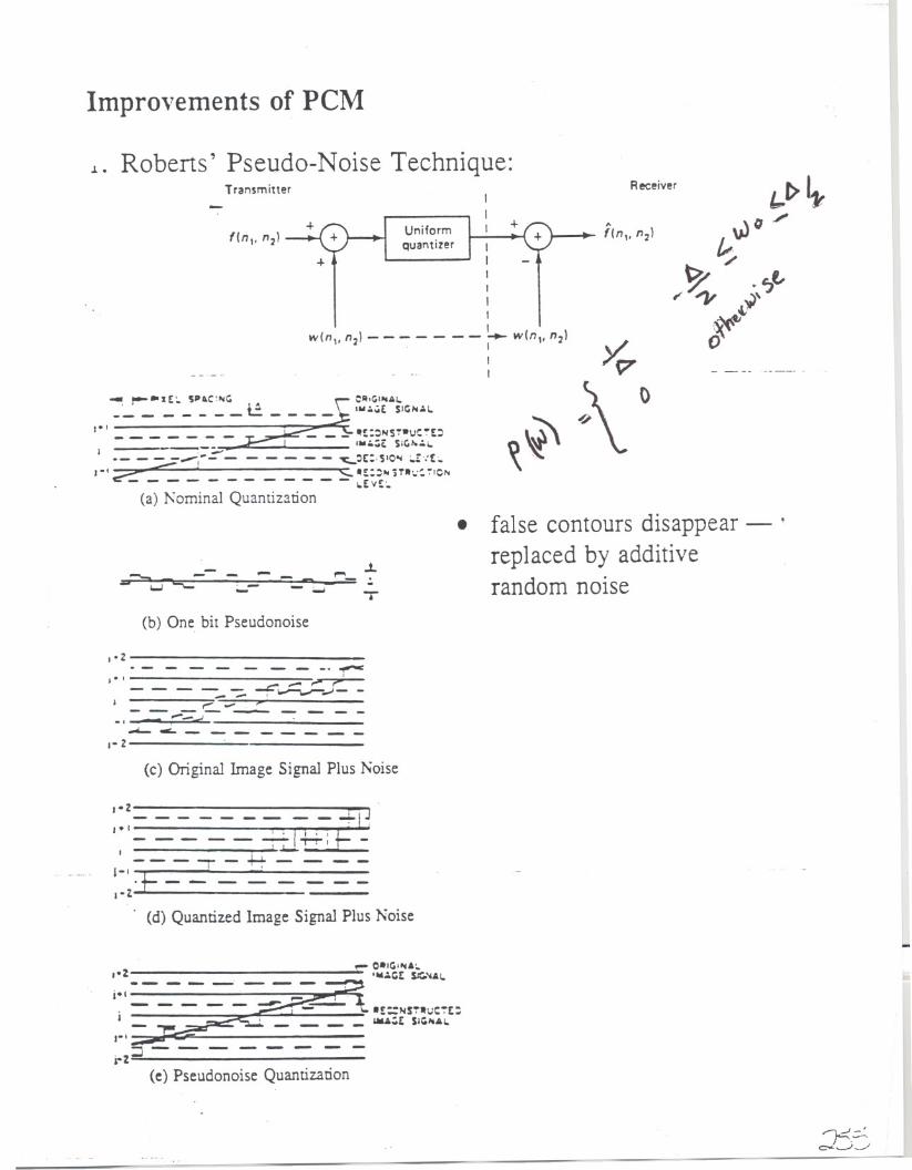
~. Roberts' Pseudo-Noise Technique:Transmitter
III +
IIIIIII
w(n,. n2)- - - - - - - ~ w(n,. n2). I1I
UniformQuantizer
+
- r-~zE:' SP~C:"'G r'".
OlllGI"'''1..'_ _ _ _ _ _ _ t.:._ _ _ _ L I...~..E $110 1.1.
,e, ~ ~'- r- _.~__ _ _ _ _ _ _ _ _ _ -_.:)"'$.u_.E;:)~_; '''..:;E su.,.~i.
-- - ~_(- - - - - - - ~:)C:;"OOj;.!.:t~,-t~ ""- "E::..)TIt..~ ~IC""- - - - - - - - - - - - ..Evt:..(a) Nominal Quantization
- .L..-= :.-"""= --- -.,. -- T
(b) One. bit Pseudonoise
I' Z - - - - - - .. .,...-,-' ",.,.,,- ,-- - - -- -:;.~ "..,-..;- -J "-""" ,------------_I -- ; J~c.________,-z
(c) Original Image Signal Plus Noise
,.z4IJ
I.',-l
----------
(d) QuantizedImage SignalPlus Noise
-- - --'.E::N~ItUc:~t:_ _ _ _ lIiIA;t $1''''''1.
,-,:::r---i-Z-
(e) PseudonoiseQuantization
+
Receiver
false contours disappear - .replaced by additiverandom noise
.
~~~~TO~Cal
Ii \flMr; '~, m. _dj""""""'HlhIi"'" TO~
Cbl
~~~~~~~TI.'I
~TI.'
Ce
Cd)
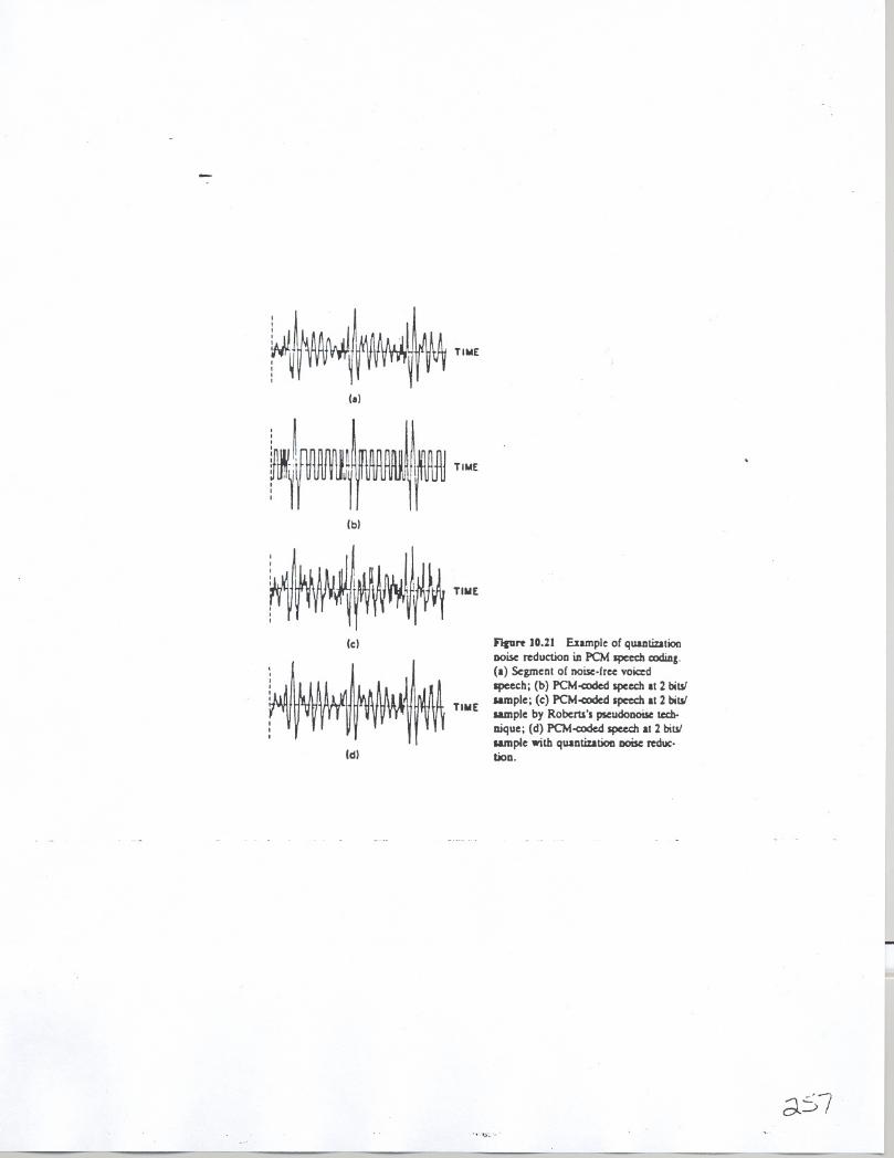
FIp" 10.21 Eumple of quanUulionnoise reduction ill PCM speech codiDl.(a) Segmenl of noise.free voiced
speech; (b) PCM-c:oded speech It 2 bilSlumple; (c:) PCM<Oded speech It 2 bilSlsample by Roberu's pseudonoisc tech-
aique; (d) PCM-c:oded speech II 2 bilSl
umple with qUlnUutioD DOise reduc.bon.
L..

" ';
. "
. ,
lal Ib)
Ic) (d)
fiKUrf 10.22 Example of quantization noise reduction in PC~I image codin~. (a) Ori~inalIma~~ of 51~ y ~l::: pixels: (bl PC~I-coded ima~.: at ~ bits pixel: Icl PC~I.coded Image al
::: tom pixel b\ Roberts's pseudonoi'e technique: Idl PC\I-coded ima~e at ::: bits piXel withquanuzatlon nOIse reduction.
Sec. 10.3 Waveform Coding 623
--"---, .~.t{~~:...-.
_. - _0 ..... ....

Delta l\1odulation (DM)
coded signal
Transmitte-rTrensminer
fin)
" A A~(n). - or - -
1 bit I 2 2quentiZ8tion
-- --;( n - 1) . r +
+II "L - __- _ - - - - - - fin)
- - -- ---_.
Receiver
Receiver
+"-
fin),II
" . ,fin -1)~ '
Slope overload
Fi~ure 10.26 Granular noise and slope-n overload distortion in delta modulation_
. needs over 2-3 bits/pixel to get good quality
. .':=..'-10: -..; i

.. .
Slope overload
- --- ------
Figure 10.26 Granular noise and ~I(lr'~'n 0\ erload dIstortion in delta modubl'vr.
quirements. and the step size ~ is chosen through some compromise between thetwo requirements.
Figure 10.:7 il!ustratesthe performance of a DM system. Figures'JU.2":"(J)and (b) show the results of D:-.t with step sizes of ~ = 80Cand lSr:c. respecti\el: .of the o\erall dynamic range of f(I1). ,,:). The original image used is the 512 0"
512-pixe1image in Figure 1O.22(a). When ~ is small [Figure 1O.2i(a.l).the granularnoise is reduced. but the slope o\'erload distortion problem is severe and theresulting image appears blurred. As we increase ~ IFigure 1O.2i(b)). the slopeoverload distortion is reduced. but the graininess in the regions where the signJIvaries slowly is more pronounced.
la) (b)
Fil1urt 10.27 E\ample of d.:lta.modulatlnn ID\I"Cl\J~d image. The onginal imag~ u,ed "the Image 10 FIgure 1U.221JI. IJI D\I..:od.:d Im..~.: \\lIh ..\ = :;r; oi th.: o\.:rall d\"naml"range. ~~fSE = IJ.~c;. S~R = 1\.3 dB: (hI D\kod.:d image \\ith ..\ = I~( (. ~\fSE ,.9.iri. S~R = IO.J dB.
626 Image Coding Chap. 10
...." . _.~'.""J:-.".
.'.~." ..:'.:~:.'.: :~~~:,:,"~... ,.-_0. .
l

I
II
j
Figurt 10.28 D:>"-coded Image al :bns'plxel. The ongmal Image u~ed I~theimage m Figure 1O.::lal. I'MSE =2,.I<;C.S!':R = 16.:!dB.
To obtain good quality image reconstruction using DM without significantgraininess or slope overload distortion. 3-4 bits/pixel is typically required. A bitrate higher than 1 bit/pixel can be obtained in DM by oversampling the originalanalog signal relative to the sampling rate used in obtainingf(nl. 1I~). Oversam-piing reduces the slope of the digital signal f(n) so a smaller .l can be used withoutincreasing the slope overload distortion. An example of an image coded by DMat 2 bits.'pixel is shown in Figure 10.28. To obtain the image in Figure 10.28. thesize of the original digital image in Figure 10.22(a) was increased by a factor oftwo by interpolating the original digital image by a factor of two along the horizontaldirection. The interpolateddigitalimagewascoded by DM with ~ = 12C;:Cofthedynamic range of the image and the reconstructed image was undersampled by afactor of two along the horizontal direction. The size of the resulting image is thesame as the image in Figure 10.27. but the bit rate in this case is 2 bits/pixel.
10.3.3 DifferentialPulseCode Modulation
Differential pulse code modulation (DPCM)'can be viewed as a generalization ofDM. In DM. the difference signal e(n) = f(n) - l(n - 1) is quantized. Themost recently coded l(n - 1) can be viewed as a prediction of f(n) and e(n) canbe viewed as the error between f(n) and a prediction of f(n). In DCPM. aprediction of the current pixel intensity is obtained from more than one previouslycoded pixel intensity. In DM. only one bit is used to code e(n). In DPCM. morethan one bit can be used in coding the error.
A DPC~1 system is shown in Figure 10.29. To code the current pixel intensityf(lIl. n~).f(n:. n!) is predicted from previously reconstructed pixel intensities. Thepredicted value is denoted by /'(nl. n!). In the figure. we have assumed thatj(nl - 1. n~)./(nl. n: - 1).j(1I1- 1. n2 - 1). ... were reconstructedpriorto coding f(nl. 11:). We are attempting to reduce the variance of
Sec. 10.3 627Waveform Coding
"" I l-z'-P

Differential Pulse Code Modulation (DPCM)
f (n 1-' 112): original image-"
f (n 1' 112): reconstructed image
Transmitter
+-
"(n" n2)
+ . - - -- ... . ..-...-
,.fIn"~ n2}
Previously coded pixel intensities" ,.fIn, - 1, n21. fIn"~ n2 - 11.
fIn, -1,n2-1),...
4,L ~
· the Auto-regressive Model parameters are obtainedfrom the image by solving a linear set of equationsor by a Markov process assumption
ReceiverfIn,. n2)
" ',.fIn, - 1, n2}' fIn"~ n2 - 1),
fIn, - 1, n2 - 1),...
4,L '
· requires 2-3 bits/pixel for g09d quality image
....

. .
-where R. is the region of (kl. k,J over which a(kl. k~) is nonzero. Typically.{(III' 11~)is obtained by linearly combining j(1I1 - 1, n2)' j(III' II: - 1), and[(II) - 1.n: - 1). Since the prediction of [(II}. II:) is made in order to reducethe variance of e(l1l. n~). it is reasonable to estimate a(kl. k2) by minimizing
E[e:U'I' II:)] = E[([(III. II:) - 2:2: a(kl. k:)j(1I1- kl. n: - k:»:]. (10.40)(k..k:,~R.
Since /(111,II~)is a function of a(kl. k:) and depends on the specific quantizer used.solving (lOAO)is a nonlinear problem. Since j(lIl. 11:)is the quantized version off(I1:. II:). and is therefore a reasonable representation of [(111.11:).the predictioncoefficients alk\. kJ are estimated by minimizing
E[
(f(lll' 11:)- 2:I a(kl. k:)[(1I1- k\. 11:- k:»;]
.,.,.k:),R.
(lO.,U)
Since the function in (lOA!) minimized is a quadratic form of arkl. k:). soh'ing(l 0..1] ) im'olves solving a linear set of equations in the form of
R,(ll' I:) = 2:2: a(k!. k:)RjU)- k]. I: - k:) (10.42),k..k:" R.
where fIll:. II;) is assumed to be a stationary random process with the correlationfunction R,(III. II;). The linear equations in (l0.4:) are the same as those usedin the estimation of the autoregressive model parameters discussed in Chapters 5and 6.
Figure 10.30 illustrates the performance of a DPCM system. Figure 10.30shows the result of a DPC:--tsystem at 3 bits'pixel. The original image used is theimage in Figure 10.22(a). The PCM system used in Figure 10.30 is a nonuniformquantizer. The prediction coefficients a(k.. k;) used to generate the example are
--. .:J.J'
'.., "f
figure 10.30 Example of differenllalpulse code modulallon (DPC~1).codedimage at 3 biwpixel. Onginal imageused is (he Image in Figure IO.:!:!(al.SMSE = :!.:!'iC. S:'\R = 16.6 dB.
~~.. ..~.,...
Sec.,0.3 Waveform Coding 629
".--,_. --- - .. -_.--.~., ~.lV""r~<O,.I.'~'~;..". _e:. :... . ", .. .. - ..
.~. . .:.;:..;; '0;:: ": .... .--.
.:."':...... .' .". ..