
Wave Optics of Synchrotron Radiation - IntechOpen · synchrotron radiation as the radiation from...
28
8 Wave Optics of Synchrotron Radiation Nikolay Smolyakov National Research Center “Kurchatov Institute”, Moscow, Russia 1. Introduction Synchrotron radiation is a unique source of infrared radiation being highly polarized, pulsed, with the broad emission band and about thousand times brighter than standard thermal source. All just mentioned synchrotron radiation adventures apply to a large choice of experimental techniques and investigations. Among them are high-pressure studies, earth science and biology, microspectroscopy, reflectance and absorption spectroscopy for surface study, time-resolved spectroscopy and ellipsometry. Interest in infrared synchrotron radiation goes back to the 1980s (Duncan & Williams, 1983). At present numerous infrared beamlines have been developed at synchrotron radiation facilities throughout the world, see, e. g., (Bocci et al., 2008; Carr & Dumas, 1999; Guidi et al., 2005; H. Kimura et al., 2001; S. Kimura et al., 2001; S. Kimura et al., 2006; Roy et al., 2006; Williams & Dumas, 1997). Efforts to improve the radiation beam characteristics lead to elaboration more and more sophisticated beamline optics. To achieve this goal, we need to know all characteristics of emitted radiation, its intensity distribution, polarization and phase distribution. In particular, the synchrotron radiation wave properties play a major role in conventional diagnostics of electron beams in storage rings (Andersson et al., 2006; Elleaume et al., 1995; Fang et al., 1996; Flanagan et al., 1999; Hs & Huang, 1993; Weitkamp et al., 2001). In this case, the image of the electron beam is formed by an optical lens. The synchrotron radiation diffraction on the lens iris aperture restricts the resolution of the beam profile measurements. Infrared synchrotron radiation was used for longitudinal beam diagnostics at FLASH free electron laser (Grimm et al., 2008; Paech et al., 2006, 2007). Recent trends show an increased usage of synchrotron radiation interferometers for high precision measurements of the electron beam sizes (Artemiev et al., 1996; Chubar, 1995; Hiramatsu et al., 1999; Katoh & Mitsuhashi, 1999; Naito & Mitsuhashi, 2010). For proper interpretation of observed data, we also need to know synchrotron radiation phase distributions. As far as we know, the paper (Sabersky, 1973) was one of the first papers to pioneer the investigation of geometrical-optical properties of synchrotron radiation coming from the curving relativistic electron beam. The phase-space techniques, commonly applied to charged beam optics, was used for analysis. The focusing of synchrotron radiation by a convex lens within the framework of geometrical optics was considered in (Green, 1976; Ogata, 1987). The qualitative agreement with the experimentally observed data was found, although the quantitative discussion needs taking into account of the diffraction effects. The synchrotron radiation treatment as a laser-like Gaussian beam with a small opening angle was performed in (Coisson & Marchesini, 1997; Kim, 1986; Ogata, 1991; Takayama et al., www.intechopen.com
Transcript of Wave Optics of Synchrotron Radiation - IntechOpen · synchrotron radiation as the radiation from...

8
Wave Optics of Synchrotron Radiation
Nikolay Smolyakov National Research Center “Kurchatov Institute”, Moscow,
Russia
1. Introduction
Synchrotron radiation is a unique source of infrared radiation being highly polarized, pulsed, with the broad emission band and about thousand times brighter than standard thermal source. All just mentioned synchrotron radiation adventures apply to a large choice of experimental techniques and investigations. Among them are high-pressure studies, earth science and biology, microspectroscopy, reflectance and absorption spectroscopy for surface study, time-resolved spectroscopy and ellipsometry. Interest in infrared synchrotron radiation goes back to the 1980s (Duncan & Williams, 1983). At present numerous infrared beamlines have been developed at synchrotron radiation facilities throughout the world, see, e. g., (Bocci et al., 2008; Carr & Dumas, 1999; Guidi et al., 2005; H. Kimura et al., 2001; S. Kimura et al., 2001; S. Kimura et al., 2006; Roy et al., 2006; Williams & Dumas, 1997). Efforts to improve the radiation beam characteristics lead to elaboration more and more sophisticated beamline optics. To achieve this goal, we need to know all characteristics of emitted radiation, its intensity distribution, polarization and phase distribution. In particular, the synchrotron radiation wave properties play a major role in conventional diagnostics of electron beams in storage rings (Andersson et al., 2006; Elleaume et al., 1995; Fang et al., 1996; Flanagan et al., 1999; Hs & Huang, 1993; Weitkamp et al., 2001). In this case, the image of the electron beam is formed by an optical lens. The synchrotron radiation diffraction on the lens iris aperture restricts the resolution of the beam profile measurements. Infrared synchrotron radiation was used for longitudinal beam diagnostics at FLASH free electron laser (Grimm et al., 2008; Paech et al., 2006, 2007). Recent trends show an increased usage of synchrotron radiation interferometers for high precision measurements of the electron beam sizes (Artemiev et al., 1996; Chubar, 1995; Hiramatsu et al., 1999; Katoh & Mitsuhashi, 1999; Naito & Mitsuhashi, 2010). For proper interpretation of observed data, we also need to know synchrotron radiation phase distributions.
As far as we know, the paper (Sabersky, 1973) was one of the first papers to pioneer the investigation of geometrical-optical properties of synchrotron radiation coming from the curving relativistic electron beam. The phase-space techniques, commonly applied to charged beam optics, was used for analysis. The focusing of synchrotron radiation by a convex lens within the framework of geometrical optics was considered in (Green, 1976; Ogata, 1987). The qualitative agreement with the experimentally observed data was found, although the quantitative discussion needs taking into account of the diffraction effects. The synchrotron radiation treatment as a laser-like Gaussian beam with a small opening angle was performed in (Coisson & Marchesini, 1997; Kim, 1986; Ogata, 1991; Takayama et al.,
www.intechopen.com

Infrared Radiation
174
1998, 1999). The important benefit to the use of this approximation is that the Gaussian beams have been much studied. It has been shown however that the Gaussian approximation has some limitations when calculating the synchrotron radiation coherence. At the same time the Gaussian beam approximation can reasonably be applied to the horizontally polarized component of synchrotron radiation only. It has been also found that the Gaussian beam approximation is poor for undulator radiation (Kim, 1986). In addition, as it was noted (Miyahara & Kagoshima, 1995), the brightness function defined by Kim can be negative (that has no physical meaning) and should therefore be modified.
The most-used scheme of diffraction phenomena implementation into synchrotron radiation theory was suggested by A. Hofmann and F. Meot (Hofmann & Meot, 1982). This technique involves the following steps. First, the synchrotron radiation from a single electron has supposedly the phase distribution of a point source that is spherically symmetrical one, while its amplitude distributions (for both horizontal and vertical polarizations) should be identical to that of an electron in a homogeneous magnetic field. Under these assumptions and supposing small observation angles, for such source we can calculate the Fraunhofer diffraction pattern. Then, assuming that we have a transverse Gaussian distribution of such point-like sources, and that they are not coherent (it corresponds to incoherent radiation of different electrons in the beam), we can calculate the image distribution by a convolution of the single-electron radiation diffraction pattern with the point sources distribution. Assume further that, instead of moving relativistic beam, we have a uniform longitudinal distribution of such immobile point sources along the circular trajectory of the beam, which are again incoherent. Then we can calculate the resultant image distribution from the electron beam by straightforward integration along longitudinal coordinate. This scheme is relatively simple, easy-to-interpret physically and allows easily estimating the optical resolution for the beam cross-section measurements. It was employed by a number of groups for optimization of the electron beam profile monitor systems and experimental date interpretations, e.g. (Andersson & Tagger, 1995; Arp, 2001; Clarke, 1994; Hs & Huang, 1993). The main weakness of this method is that some steps in this scheme are not deduced from the fundamental principles of radiation theory that is to say from the Maxwell equations. Close inspection of this model shows that some assumptions seem not sufficiently self-consistent. Thus, considering the synchrotron radiation as the radiation from the immobile point sources distributed uniformly along electron’s trajectory, we in fact presume that the radiation, generated by the electron at neighboring sections of its path, are incoherent, but this is not the case. The simplest counter example is undulator radiation, where the radiation, emitted by the electron at different periods (5-10 and more cm in length), is coherent. Accordingly, there is no reason to expect the opposite for synchrotron radiation. Rather, we should expect that the radiation from different parts of the electron trajectory is coherent in the case of synchrotron radiation as well.
In terms of wave optics a consistent definition of the problem is as follows. Let a physical device consists of multiple optical parts. Each part has characteristics known beforehand. It is sufficient to know the radiation wave amplitude and phase at every point of the device entrance window in order to take advantage of the Helmholtz - Kirchhoff integral theorem (Born & Wolf, 1986). If these values are known, one can calculate the distribution of the radiation intensity on the device output screen.
The analysis of synchrotron radiation phase distribution based on the fundamental radiation principles was presented at the Eleventh Russian Conference on the usage of Synchrotron Radiation (Novosibirsk, 1996) (Smolyakov, 1998a, 1998b). Using exact solutions of the Maxwell
www.intechopen.com

Wave Optics of Synchrotron Radiation
175
equations, the expansion of the synchrotron radiation phase in powers of small observation angles was obtained. A leading quadratic term of this expansion shows that synchrotron radiation by its phase distribution nature is much closer to the radiation emitted by an immobile point source rather than to the longitudinally extended source according to the geometrical-optical approach mentioned above. At the same time the correction cubic term produces a self-aberration effect of synchrotron radiation. The synchrotron radiation exhibits a searchlight effect which manifests itself in the amplitude distribution non-homogeneity in the vertical direction. Using the known amplitude and phase distributions, the intensity distribution of the focused synchrotron radiation from one electron (single electron image) was computed (Smolyakov, 1998c). The effect of the lens aperture on the optical resolution of the electron beam profile measurement system by means of synchrotron radiation was also analyzed. Later the similar results were obtained in the paper (Bosch, 1999), in the part which deals with the synchrotron radiation focusing by a reflecting sphere with an aperture.
An accurate simulation of synchrotron radiation propagation through the beamline optical system inevitably needs the application of specialized computer codes. Nowadays two codes are mostly in use: the code SRW (Chubar & Elleaume, 1998) and the code PHASE (Bahrdt, 1997, 2007). Comparison studies of these codes may be found in (Bowler et al., 2008). Some distributions of focused synchrotron radiation with and without phase corrections were simulated with the help of SRW (Chubar et al., 1999, 2001).
The codes, which are based on the wave propagation, are precise but time consuming. It should be mentioned that simpler and hence faster approaches are also used for analysis of beamline optical system properties (Ferrero et al., 2008).
In this chapter we will consider solely the case of standard synchrotron radiation, namely, the radiation generated by highly relativistic electrons while they pass through the uniform magnetic field of bending magnets in storage rings. Intensity distributions of synchrotron radiation, as well as its polarization properties, have been studied quite intensively and are widely covered in the literature. The amplitudes of horizontally ( ) and vertically ( )
polarized wave components of synchrotron radiation are expressed in terms of modified Bessel functions. Although the first formulas for the wave amplitudes were derived more than 60 years ago, regular study of the synchrotron radiation phase distributions started relatively recently, about dozen years ago and not yet analyzed in full measure. Here an exact expression for the phase distribution in synchrotron radiation wave will be derived. Surprisingly, the resultant exact formula is written in terms of elementary functions only, though this formula is rather cumbersome. The lens aperture effect on the focused radiation intensity distribution is analyzed.
We do not consider edge radiation in this chapter. A comprehensive list of papers on edge radiation can be found in (Geloni et al. 2009a, 2009b; Korchuganov & Smolyakov, 2009; Smolyakov & Hiraya, 2005).
2. Qualitative analysis of synchrotron radiation wave properties
2.1 Wave optics of convex lens
To gain greater insight into physics of synchrotron radiation wave optics, let us consider a
standard case of the point source radiation focusing by a refractive lens, see Fig. 1. Within
www.intechopen.com
Infrared Radiation
176
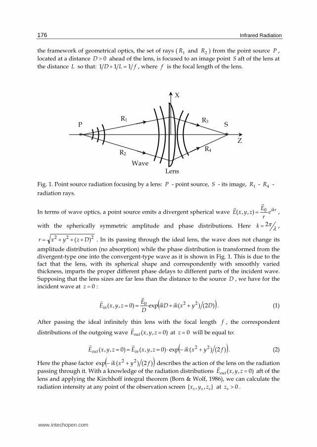
the framework of geometrical optics, the set of rays ( 1R and 2R ) from the point source P ,
located at a distance 0D ahead of the lens, is focused to an image point S aft of the lens at
the distance L so that: fLD 111 , where f is the focal length of the lens.
Fig. 1. Point source radiation focusing by a lens: P - point source, S - its image, 1R - 4R -
radiation rays.
In terms of wave optics, a point source emits a divergent spherical wave ikrer
EzyxE 0),,(
,
with the spherically symmetric amplitude and phase distributions. Here 2k ,
222 )( Dzyxr . In its passing through the ideal lens, the wave does not change its
amplitude distribution (no absorption) while the phase distribution is transformed from the divergent-type one into the convergent-type wave as it is shown in Fig. 1. This is due to the fact that the lens, with its spherical shape and correspondently with smoothly varied thickness, imparts the proper different phase delays to different parts of the incident wave.
Supposing that the lens sizes are far less than the distance to the source D , we have for the
incident wave at 0z :
)2()(exp)0,,( 220 DyxikikDD
EzyxEin
. (1)
After passing the ideal infinitely thin lens with the focal length f , the correspondent
distributions of the outgoing wave )0,,( zyxEout
at 0z will be equal to:
)2()(exp)0,,()0,,( 22 fyxikzyxEzyxE inout . (2)
Here the phase factor )2()(exp 22 fyxik describes the action of the lens on the radiation
passing through it. With a knowledge of the radiation distributions )0,,( zyxEout
aft of the
lens and applying the Kirchhoff integral theorem (Born & Wolf, 1986), we can calculate the
radiation intensity at any point of the observation screen },,{ sss zyx at 0sz .
Z R4 R2
Wave Lens
R3 R1
X
S P
* *
www.intechopen.com
Wave Optics of Synchrotron Radiation
177
A s
soutsss dxdy
r
ikrzyxE
izyxE
)exp()0,,(),,(
, (3)
where s
sssssss
z
yyxxzzyyxxr
2
)()()()(
22222 is the distance of the lens
element dxdy from the point },,{ sss zyx at the observation screen and the integral is taken
over the lens aperture A . The standard simplification of the Kirchhoff integral was made by
neglecting the small terms of the order of D , L and f . The expression (3) displays
the well-known Huygens-Fresnel Principle: every point of a wave front )0,,( zyxEout
may
be considered as a center of a secondary disturbance which gives rise to spherical waves
s
s
r
ikr )exp(. The total disturbance at the observation point },,{ sss zyx is the result of all these
secondary waves interference.
Substituting Eq. (1) and Eq. (2) into Eq. (3), we get:
dxdyyyxxzikyxfzD
ikDz
EizyxE
Asss
sssss
exp
1112exp),,( 220
(4)
Assume for simplicity that the lens is rectangular in shape: xlx , yly , where xl2 and
yl2 are the lens horizontal and vertical sizes respectively. Considering the integral (4) in the
image plane Lzs , where 0111 fLD , we get:
s
s
s
syxsss ll
DL
EiLzyxE
)sin()sin(4
),,( 0
, (5)
where sx
s xL
l
2 , s
ys y
L
l
2 . The radiation intensity is proportional to
2),,( sss zyxE
.
Notice that the focused spot has horizontal and vertical sizes yxlL , respectively, which are
in inverse proportion to the lens aperture sizes yxl ,2 . Second, the radiation intensity at the
spot center 0sx , 0sy , is proportional to 22yx ll . It is physically clear that with the lens
horizontal aperture xl2 increasing, the photon flux through the lens varies proportionally
and the horizontal size of the spot is correspondently diminished. So, the density is
quadratic in xl2 . Similar to the vertical aperture yl2 .
2.2 Time-domain analysis of synchrotron radiation
Here, we will consider synchrotron radiation in the time domain and describe it in terms of electric field of the emitted wave and its arrival time to an observer. A relativistic electron generates synchrotron radiation in the uniform magnetic field of a storage ring bending magnet. Let us consider a physical experiment with a geometry shown in Fig. 2. The electron rotates anticlockwise.
www.intechopen.com

Infrared Radiation
178
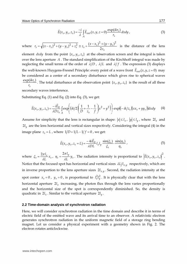
Fig. 2. Typical layout of synchrotron radiation observation: 1 – electron trajectory; 2, 3, 4 – synchrotron radiation field pulses; A-D-B – device entrance window.
For simplicity, we will restrict here our qualitative analysis to the case of radiation in the
storage ring median plane XOZ . Briefly, the idea of analysis is as following.
In uniform magnetic field, an electron generates synchrotron radiation homogeneously
along its orbit. In the median plane on which the electron moves, the wave shape of the
emitted radiation (the electric field temporal structure, curves 2, 3 and 4 in Fig.2) is the same
at any observer positions in this plane (e.g., points A , D and B ) provided the distances
from the emitting points a , O and b respectively to the observers are the same. In the strict
sense the distances aA , OD and bB are slightly different from each other. Here, however,
this difference can be neglected being negligibly small in comparison with the distance
itself. The difference in the field between observers A , D and B is in the relative arrival
time A , D and B of the radiation field. The distinctions between arrival time A ,
D and B cannot be neglected since the quantity c is not negligibly small as compared
with the radiation wavelength, where c is the speed of light. This arrival time difference
gives rise to the phase difference in the frequency domain.
Let a relativistic electron moves along its circular orbit in a horizontal plane XOZ (the
magnetic field is aligned with the vertical Y-axis). It is convenient to choose a frame of
reference in such a way that at the initial moment 0t the electron was at the origin of the
coordinates with its velocity vector directed along the Z- axis. Then the equations of the
electron motion are:
( ) cos( ),
( ) 0,
( ) sin( ).
x
y
z
r t R R t
r t
r t R t
(6)
A
D
B
4
3
2
b
C
G
F
Z
X
a O
1
www.intechopen.com
Wave Optics of Synchrotron Radiation
179
( ) sin( ),
( ) 0,
( ) cos( ).
x
y
z
t t
t
t t
(7)
Here, R is the electron orbit radius, is the angular velocity of the electron Rc ,
is the electron reduced velocity dt
trd
ct
)(1)(
, constt )( , c is the speed of light.
Let us consider a points at the observation screen (plane A-D-B, device entrance window),
which is transversal to the Z-axis. The observer, who is at the point },0,0{ D , will detect the
peak in the electric field distribution of the radiation wave (synchrotron radiation field
pulse) at the moment cD . This is obvious because, at time 0t the electron was at the
origin of coordinates, and the vector of its velocity pointed to the observer with coordinates
},0,0{ D . If there are other observers located at some different points A or B of the
observation screen, they will detect a similar synchrotron radiation pulse. Nevertheless, these observers will detect the signal peak at different instants. Obviously, the time detected
by each observer consists of two components. The first part )( se xt is the time, when the
electron was at such point of its orbit )( etr
from where the velocity vector pointed to the
observer with coordinates },0,{ DxX ss (points a or b in Fig.2). The other part is the time of
radiation propagation from position of the electron ))(( se xtr
to the point at the observation
screen },0,{ DxX ss , that is the quantity ))((1
ses xtrXc
.
At some moment t the electron’s position was )(tr
and its velocity was pointed to the
observer with the coordinates },0),({ Dtxs . It can easily be shown from Fig. 2 that:
tgtrDtrtx zxs ))(()()( , (8)
where t .
It follows from Eq. (6) and Eq. (8) that:
)cos(
)()(t
RttgDRtxs , (9)
The case 0)( tz (i.e. 0)cos( t ) is of interest for our analysis. By using the relation
)(cos1)(1 22 tg , we can get from Eq. (9):
0)(2)()()(2)( 2222 tRxtxttgtxRDttgRD sss . (10)
This equation is quadratic in terms of )( ttg with the solution:
22
222 )()())((
RD
xRDRDxRRxttg ss
se . (11)
www.intechopen.com
Infrared Radiation
180
This is precisely the solution of the two solutions of the quadratic equation (10) which gives
0)0( se xt . Here we consider the quantity sx as an independent variable. Thus, )( se xt is
the moment when the electron, having the position ))(( se xtr
, points to the observer with the
coordinates },0,{ Dxs . As a result, we have the following expression for the arriving time
)( sx of synchrotron radiation pulse:
))((1
)()( sesses xtrXc
xtx . (12)
It is convenient to define the function )( sx :
22
222 )()(arctan)(
RD
xRDRDxRRx ss
s , (13)
with 0)0( sx and )()(1
)( ssse xc
Rxxt . In essence the function )( sx is the angle
t , at which the electron velocity )(t points to the observer },0,{ DxX ss , see Fig. 2.
As a result, we will get the following expression for the arriving time )( sx :
22 ))(sin())(cos(1
)()( sssss xRDxRRxc
xc
Rx . (14)
Looking ahead, we note that the value of )(2 sxc is a phase of the radiation with the
wavelength .
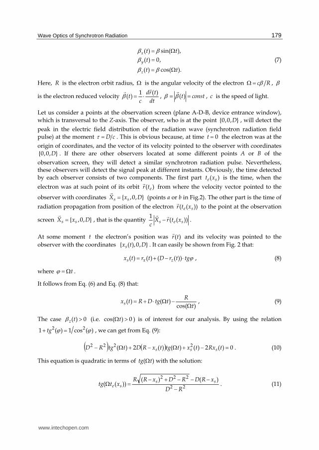
The sx -dependence of the function )0()()( ss xcxc is shown in Fig. 3a. The
parameters of Siberia-2 storage ring were used for this simulation: electron beam energy 2.5
GeV (electron reduced energy is equal to =4892), electron orbit radius R =4905.4 mm,
synchrotron radiation critical energy 7.2 keV (Korchuganov et al., 2005; Korchuganov &
Smolyakov, 2009). The distance of the observation plane from the emission point was taken
to be D = 20000 mm.
The quadratic behaviour of retardation )( sxc suggests that the synchrotron radiation
phase distribution is very close to that of an immobile point source. Closer examination of
the derived above expressions shows that the correspondent equivalent point source, which
produces the similar phase distribution, should be placed at the point with coordinates
0,0,2 2
R. Practically the value
22R
is very small; in our case it is equal to 410 mm. The
front position for this point source is described by the following expression:
222222 )2()2()( DRDRxxd ss . (15)
www.intechopen.com

Wave Optics of Synchrotron Radiation
181
Fig. 3. (a) Synchrotron radiation retardation )( sxc versus observer horizontal position sx .
(b) Difference in positions between synchrotron radiation front and point source front.
The difference between the synchrotron radiation front position )( sxc and the point
source front position )( sxd is shown in Fig. 3b. It should be pointed out that this difference
is small, less to 310 mm at the horizontal aperture boundaries 200 mm in our example. It
means that the synchrotron radiation phase can be considered at zero approximation as the
spherically symmetric phase of the correspondent immobile point source. Expanding Eqs.
(13) – (15) in powers of sx we get the following approximation for the difference in front
positions of synchrotron radiation and point source front (Fig. 3b):
33 6)()( DRxxdxc sss . (16)
It describes the curve in Fig. 3b with a very good accuracy. Though this term is cubic in sx
and is very small at first glance, it plays an important part in synchrotron radiation imaging, as we will see below.
Finally we will give another well-known example, which on closer examination also shows
the phase distribution of synchrotron radiation. Let an electron moves anticlockwise along
the circle trajectory )(tr
, see Fig. 4. The radiation pulse (the maximum of the generated
electric field) moves along the velocity vector )(t . At time it will reach the point
)()(
)()( tct
trX
. Let us substitute Eqs. (6) and (7) into this relation, fix an
observation point in time and consider the set of points in time t when the radiation was
emitted: t . We will get the simultaneous distribution of the radiation pulses in the space,
the well-known spiral radiation pattern, see Fig. 4. Some comments to this pattern can be
found in (Jackson, 1999). The numbers of computed diagrams of electric field lines of
radiating electron are published by (Tsien, 1972), see also (Shintake, 2003).
-200 -100 0 100 200
0,0
0,2
0,4
0,6
0,8
1,0
c, m
m
Horizontal coordinate of the screen, mm
-200 -100 0 100 200-0,0010
-0,0008
-0,0006
-0,0004
-0,0002
0,0000
0,0002
0,0004
0,0006
0,0008
0,0010
cpo
int
sou
rce
fro
nt
, m
m
Horizontal coordinate of the screen, mm
a b
www.intechopen.com
Infrared Radiation
182
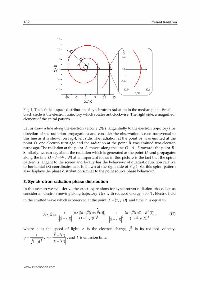
Fig. 4. The left side: space distribution of synchrotron radiation in the median plane. Small black circle is the electron trajectory which rotates anticlockwise. The right side: a magnified element of the spiral pattern.
Let us draw a line along the electron velocity )(t tangentially to the electron trajectory (the
direction of the radiation propagation) and consider the observation screen transversal to this line as it is shown on Fig.4, left side. The radiation at the point A was emitted at the point O one electron turn ago and the radiation at the point B was emitted two electron
turns ago. The radiation at the point A moves along the line BAO towards the point B .
Similarly, we can say about the radiation which is generated at the point U and propagates
along the line WVU . What is important for us in this picture is the fact that the spiral pattern is tangent to the screen and locally has the behaviour of quadratic function relative to horizontal (X) coordinates as it is shown at the right side of Fig.4. So, this spiral pattern also displays the phase distribution similar to the point source phase behaviour.
3. Synchrotron radiation phase distribution
In this section we will derive the exact expressions for synchrotron radiation phase. Let us
consider an electron moving along trajectory )(tr
with reduced energy 1 . Electric field
in the emitted wave which is observed at the point },,{ DyxX and time is equal to:
3
2
23 ))(1(
))(1))(((
)())(1(
)]]())([([
)(),(
tn
ttn
trX
e
tn
ttnn
trXc
eXE
, (17)
where c is the speed of light, e is the electron charge, is its reduced velocity,
21
1
, )(
)(
trX
trXn
, and t is emission time:
-10 -5 0 5 10 15
-10
-5
0
5
10
15
W
V
U
OB
X/
R
Z/R
A
12,5 12,6
-0,6
0,0
0,6
X/
R
Z/R
B
www.intechopen.com
Wave Optics of Synchrotron Radiation
183
)(1
trXc
t . (18)
The radiation spectrum with wavelength is defined by the Fourier transform:
dXE
ciXE ),()
2exp(),(
~ , (19)
The unit vectors of polarization q
and q
are directed transversally to the radiation
propagation and describe horizontally and vertically polarized radiation correspondently. The number of photons per unit time per unit area per unit relative spectral interval emitted
by an electron beam with current I is equal to:
2
,2,
),(~
4)(
XEqe
Ic
ddsd
dN
(20)
It can easily be shown by the direct differentiation of Eq. (18) that:
))((1)(
tnt
t . (21)
Using Eq. (21) we can write: t
T
tdtnTt ))(1()()( , or:
),()(1
)( tTfTrXc
Tt , (22)
where
t
T
tdtntTf ))(1(),( . (23)
Here T is an arbitrary quantity to be defined below. It is important to keep in mind that T does not depend on time t .
Substituting Eqs. (17) and (18) into Eq. (19) and changing the integration from the independent variable to the variable t with the help of Eq. (21), we get:
),(~
),(exp),(~
0 XEXTiXE , (24)
where
)(2
),( TrXcTXT
(25)
dtn
n
trX
c
ntrX
nntTf
ci
c
eXE
2
2
220)1(
)1)((
)()1()(
]])[([)),(
2exp),(
~
(26)
www.intechopen.com
Infrared Radiation
184
Once the radiation intensity is calculated, the Eq. (24) should be substituted into Eq. (20) and
the phase ),( XT is of no concern. But the applications of optical elements generate a need
for the radiation phase ),( XT accurate calculations.
It is a matter of direct verification to prove the following exact relation:
22
2
22)()1()()1(
)1)((
)()1()(
]])[([
trX
nc
ntrX
n
dt
d
n
n
trX
c
ntrX
nn
(27)
Substituting Eq. (27) into Eq. (26) and integrating by parts with using Eq. (23), we get:
)(
)()( 2
1)()),(2
exp2
),(~
0trX
dtt
trX
itntTf
ci
eiXE
(28)
It should be noted that so far the exact formulas (17) - (28) were used and no approximations were employed. Particular attention should be paid to the phase as its scale of variation is
very small, the phase changes by 2 along the radiation wavelength. Furthermore, we will
derive the exact expression for synchrotron radiation phase distribution which is given by Eq. (25). At the same time we will apply the standard far-field approximation in the radiation amplitudes calculations, see Eq. (28).
We detect the radiation at the point },,{ DyxX , where D is considered to be much greater
than the size of the emission region. Then we can write DtrX )(
, Dxnx , Dyny
and certainly we can neglect by the small term )( 2 trXi in Eq. (28). The polarization
vectors are
[ ] [ ] ,
[ ],
q j n j n
q n q
(29)
where j
is the unit vector along vertical Y-axis. Let us consider the radiation at small
observation angles: 1, yxn so that 221 yxz nnn is approximately equal to:
)(5.01 22yxz nnn . (30)
Similarly, the expansion for )()( 22 tt xz is equal to:
))((5.01)( 22 tt xz . (31)
It can be easily derived from Eq. (30) and Eq. (31) that:
www.intechopen.com

Wave Optics of Synchrotron Radiation
185
222 )(5.0)(1 yxx nnn . (32)
Then we obtain from Eq. (28):
dttntTfc
iD
eiXE yx ,,0 )()),(
2exp
2),(
~
(33)
and
t
Tyxx tdntntTf 2222
2)(1
2
1),( . (34)
Usually, calculating synchrotron radiation intensity, the observation point is chosen in such
a way that 0xn thus substantially simplifying the resultant calculations. It is possible for
the amplitudes calculations because they are axially uniform and depends on vertical angle
only. In this case we obtain
),(~
XEq as a purely real function and
),(
~XEq as a
purely imaginary function. But this simplification is not applicable when calculating the phase distribution of synchrotron radiation and we need to apply more accurate calculating procedure.
Now we determine the parameter T by making it equal to )(xte , where x is the horizontal
coordinate of the observation point },,{ DyxX and the function )(xte is given by Eq. (11).
By using the relation )(
)(
t
ttg
z
x , see Eqs. (7), we get from Eq. (8):
))((
))((
))((
))((
xt
xt
n
n
xtrD
xtrx
ez
ex
z
x
ez
ex
. (35)
Saving the linear terms of Eq. (35), which is to say that 1zn and 1z , we get:
D
xnxt xex ))(( and hence in the frame of linear approximation:
tntxttxtt xeex )sin())(cos()cos())(sin()( , where txtt e )( .
Substituting this relation into Eq. (34) and denoting t , where Rc , we obtain:
322
3 3
11
2)),(( ye n
c
RtxtTf . (36)
Using Eq. (36), we can easily derive from Eq. (33) the well-known expressions for synchrotron radiation fields:
220 1
4),(
~yniA
Dc
eXE , (37)
www.intechopen.com
Infrared Radiation
186
222
0 14
),(~
yy nAinDc
eiXE (38)
where 3
232
3 4
3
cR
, 33
4
R
c is the synchrotron radiation critical wavelength,
xAi and xiA are the Airy function and its derivative.
We have obtained standard formulas, describing the synchrotron radiation amplitudes 0~E
and 0~E in the far-field approximation. The phases of the amplitudes 0
~E and 0
~E are
constant (independent of the observation point position), so the phase dependence of the
synchrotron radiation is described by the function )),(( XxtT e
, see Eq. (25):
))((
1)(
2)),(()( xtrX
cxt
cXxtTX eee
(39)
Notice that )(xte is the moment when the electron, having the position ))(( xtr e
, points to
the observer with the coordinates },0,{ Dx . The second term ))((1
xtrXc
e is the time
interval required for the light passing from the position of the electron ))(( xtr e
to the
observer position },,{ DyxX . Thus, we have obtained a physically reasonable result that
the synchrotron radiation phase is proportional to the arrival time of the maximum of function ),( XE
: the arrival time is equal to )2()( cX .
Let us determine the following variables: D
R , D
xx ,
D
yy and a function )( x :
2
22
1
)(1)(arctan)(
xx
x. (40)
Notice that 0)0( x . Then the phase distribution of synchrotron radiation is described
by the following exact expression:
222 )cos()sin1(
2)( yx
DX
. (41)
It is worth noting that we have obtained, as a result, the exact analytic expression involving only elementary functions. It is important to outline also that the phase difference, rather
than the phase value )(X , has a physical sense. In other words, the phase is defined up to
a constant value identical for all the points of the optical device entrance window.
4. Synchrotron radiation regarded as a point-source radiation
Consider now the phase )(X at the observation point },,{ DyxX , where Dx ,
Dy . Analysis shows that the function )(X has a minimum in the vicinity of the point
www.intechopen.com

Wave Optics of Synchrotron Radiation
187
},0,0{ D . Let us expand this phase in a power series with respect to the small transverse
angles D
xx and
D
yy up to the third power inclusive. This expansion has the form:
)()()( 320 XXX , (42)
)8(12 422
0
DRD , (43)
2
2
222
)( yxD
X
, (44)
23
33
1)( yxx
RX
. (45)
If both angles x and y are sufficiently small, one can neglect the term )(3 X , which is of
the third order of smallness. The size of the corresponding region can be evaluated from
condition 5.0)(3 X
. As a result, one finds that the term )(3 X can be neglected if:
3,1
cyx
. (46)
In this case )()( 2 XX and the distribution of the synchrotron radiation phases
coincides with the phase distribution of an immobile point source located at the point
0,0,2 2R
. The quantity 22
R usually is very small and can be neglected. Then it is seen
from Eq. (44) that the equivalent immobile point source is located at the origin of the coordinates. In this case the synchrotron radiation properties are rather well understood. The spatial distributions of the synchrotron radiation amplitudes are described by Eqs. (37) and (38). The synchrotron radiation phase distribution inside the angle limited by Eqs. (46) coincides with that of an equivalent spherical wave propagating from the origin of the
coordinates and is described by Eq. (44). For the Siberia-2 storage ring ( =4892, c =0.175
nm, =6000 nm) the region given by Eq. (46) is rather large: 6.6, yx mrad. Any decrease
in the radiation wavelength reduces the size of this region.
All the above stated concerned a single relativistic electron moving along the circular trajectory with zero initial conditions see Eqs. (6) and (7) and Fig. 5. This electron passed
through the origin of the coordinates, where its velocity was directed along the Z -axis. The immobile point source, which is equivalent in phase distribution to the synchrotron radiation generated by this electron, is at the origin of the coordinates. However, in practice the electron beam has always some spread in both positions and angles. It is clear that for electrons with different orbits the locations of the equivalent immobile point sources would
www.intechopen.com

Infrared Radiation
188
also be different. The explicit calculation of the position of the equivalent point source for an arbitrary electron involves rather cumbersome formulas and is beyond the scope of this chapter. However, for an electron with a trajectory lying in the storage ring median plane, the solution is reasonably simple.
Fig. 5. Equivalent immobile point sources positions sketch: the point source 0,0,)2( 2R
for the electron 1 with zero initial conditions and the point source cc ,0, for the electron
2 with nonzero initial conditions.
Let us consider now an electron moving along a circular trajectory which lies in the XOZ -
plane and intersects the X -axis at some point 0x so that the electron initial position is 0,0,0x . Let the vector 00 ,0, zx be the reduced velocity of the electron at this initial
point and 0x be small. According to the analysis, the phase distribution of the synchrotron
radiation in this case coincides with the phase distribution of an equivalent spherical wave
outgoing from a point source with the coordinates cc ,0, , where:
2020 5.0
2xc R
Rx , 0xc R . (47)
Up to )2( 2R , this point source lies on the electron orbit. Namely, it is the point of
tangency of a normal to the screen with the electron circular trajectory, see Fig.5. Notice that
the transverse (X) coordinate c depends mainly on the electron initial position 0x , while
its longitudinal (Z) coordinate c is determined by the electron initial angle 0x .
Let us consider a relativistic beam, in which all the electron trajectories lie in the XOZ -plane (zero vertical emittance condition). Nevertheless, these electrons are spread over horizontal positions and angles. In the vicinity of the optical device window (as defined by Eq. (46)) the synchrotron radiation of such a beam can be regarded as a radiation from a set of immobile point sources, whose coordinates are defined by Eqs. (47). The phases of the synchrotron radiation emitted by each of the electrons coincide with the phases of the radiation emitted by the corresponding immobile point sources. However, according to Eqs. (37) and (38), the radiation amplitudes of the immobile point sources are modulated in the vertical direction. This approach permits us to substitute of a determination of a pattern produced by the distributed immobile point sources for the calculation of the image created by the synchrotron radiation. The solution of this problem has been comprehensively examined by the wave optics (Born & Wolf, 1986). It is significant that the length along Z-axis of this immobile point sources distribution is determined by the electron beam angular spread rather than the orbit curvature and a focusing lens aperture as implied in the geometrical optics approach (Hofmann & Meot, 1982).
X O
x0
},0,{ cc
0 1 2
D Z
www.intechopen.com

Wave Optics of Synchrotron Radiation
189
It should be said in closing that the term )(3 X , which was outside our analysis here, plays
an important role in synchrotron radiation optics, determining its self-aberration effect.
5. Focusing of synchrotron radiation
Let us consider the standard experimental layout for synchrotron radiation imaging shown
in Fig. 6. For simplicity sake the geometry with an ideal refractive lens is considered. The
distance between the origin of coordinates and lens is equal to D , the distance from the lens
to the observation screen is equal to L .
Fig. 6. Synchrotron radiation imaging experiment geometry: 1 – electron trajectory; 2 – lens, 3 – observation screen.
The ideal lens with focal length f does not change the synchrotron radiation amplitudes
but adds an extra shift in the radiation phase distribution:
)()(exp),,(),,( 22 fyxiDzyxEDzyxE inout . (48)
Here ),(~
)(exp),,( 0 XEXiDzyxEin
is the synchrotron radiation field. Its amplitudes
0
~E
are given by Eqs. (37) and (38) and the phase )()()( 32 XXX is given by Eqs. (42)
– (45). Notice that the cubic term )(3 X will also be taken here into account.
The radiation field at the point },,{ LDzyxX ssss of the observation screen can be
found by applying the Kirchhoff integral theorem (Born & Wolf, 1986):
A s
soutsss dxdy
r
ikrDzyxE
izyxE
)exp(),,(),,(
, (49)
sX
sr 2
D
)(~
, XEin
X 3
Z L
O
1
)(~
, XEout
www.intechopen.com
Infrared Radiation
190
where L
yyxxLLyyxxr ss
sss2
)()()()(
22222 is the distance of the lens
element dxdy from the observer },,{ LDzyxX ssss and A is the lens aperture, which
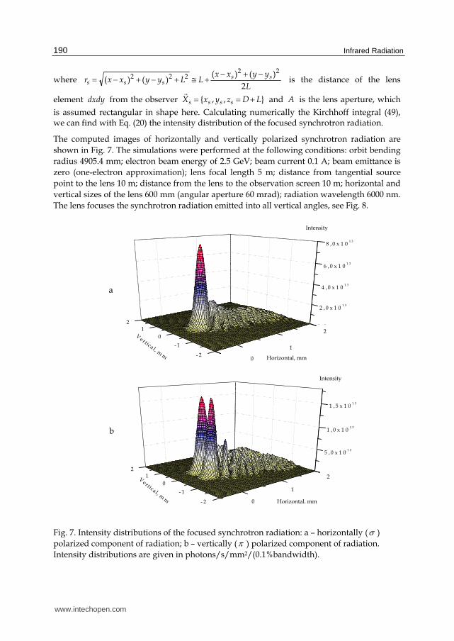
is assumed rectangular in shape here. Calculating numerically the Kirchhoff integral (49), we can find with Eq. (20) the intensity distribution of the focused synchrotron radiation.
The computed images of horizontally and vertically polarized synchrotron radiation are
shown in Fig. 7. The simulations were performed at the following conditions: orbit bending
radius 4905.4 mm; electron beam energy of 2.5 GeV; beam current 0.1 A; beam emittance is
zero (one-electron approximation); lens focal length 5 m; distance from tangential source
point to the lens 10 m; distance from the lens to the observation screen 10 m; horizontal and
vertical sizes of the lens 600 mm (angular aperture 60 mrad); radiation wavelength 6000 nm.
The lens focuses the synchrotron radiation emitted into all vertical angles, see Fig. 8.
Fig. 7. Intensity distributions of the focused synchrotron radiation: a – horizontally ( )
polarized component of radiation; b – vertically ( ) polarized component of radiation.
Intensity distributions are given in photons/s/mm2/(0.1%bandwidth).
- 2
- 1
0
12
0 ,0
2 , 0 x 1 01 3
4 , 0 x 1 01 3
6 ,0 x 1 01 3
8 , 0 x 1 01 3
Vertica l, m
m
Intensity
0
1
Horizontal, mm
2
- 2
- 1
0
12
0 , 0
5 , 0 x 1 01 2
1 , 0 x 1 01 3
1 , 5 x 1 01 3
Vertica l, m
m
Intensity
Horizontal, mm 0
1
2
b
a
www.intechopen.com
Wave Optics of Synchrotron Radiation
191
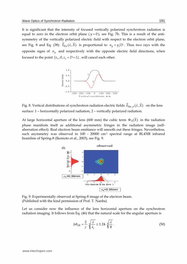
It is significant that the intensity of focused vertically polarized synchrotron radiation is
equal to zero in the electron orbit plane ( 0y ), see Fig. 7b. This is a result of the anti-
symmetry of the vertically polarized electric field with respect to the electron orbit plane,
see Fig. 8 and Eq. (38): ),(~
0 XE is proportional to Dyny . Thus two rays with the
opposite signs of yn and respectively with the opposite electric field directions, when
focused to the point },0,{ LDzx ss , will cancel each other.
Fig. 8. Vertical distributions of synchrotron radiation electric fields ),(~
,0 XE on the lens
surface: 1 – horizontally polarized radiation, 2 – vertically polarized radiation.
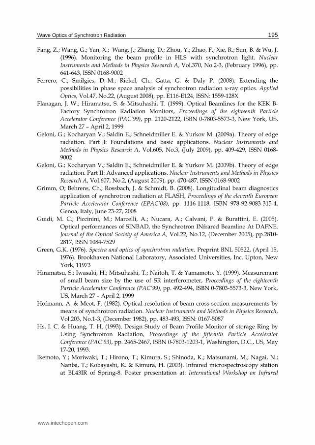
At large horizontal aperture of the lens (600 mm) the cubic term )(3 X in the radiation
phase manifests itself as additional asymmetric fringes in the radiation image (self-aberration effect). Real electron beam emittance will smooth out these fringes. Nevertheless, such asymmetry was observed in 100 - 20000 cm-1 spectral range at BL43IR infrared beamline of Spring-8 (Ikemoto et al., 2003), see Fig. 9.
Fig. 9. Experimentally observed at Spring-8 image of the electron beam. (Published with the kind permission of Prof. T. Nanba)
Let us consider now the influence of the lens horizontal aperture on the synchrotron radiation imaging. It follows from Eq. (46) that the natural scale for the angular aperture is
33 1.242
RcSR
. (50)
- 3 0 0 - 2 0 0 - 1 0 0 0 1 0 0 2 0 0 3 0 0- 1 , 0
- 0 , 5
0 , 0
0 , 5
1 , 0
V e r t i c a l c o o r d i n a t e , m m
Ele
ctri
c fi
eld
s 1
2
www.intechopen.com

Infrared Radiation
192
For the Siberia-2 storage ring with the orbit bending radius R 4905.4 mm and for 6000
nm this value is equal to 3.13 SR mrad. Fig. 10 shows the computed radiation intensity
distributions in the electron orbit plane 0y . The simulations were performed under the
same conditions as above except for the lens horizontal size. The lens horizontal aperture
xl2 was taken equal to 66 mm, 132 mm, 264 mm and 528 mm, that is the lens horizontal
angular aperture Dlxlens 2 is equal to SR5.0 , SR , SR2 and SR4 respectively.
Fig. 10. Intensity distributions (photons/s/mm2/(0.1%bandwidth)) in the median plane of
the focused synchrotron radiation for different horizontal angular aperture lens of the lens:
a - SRlens 5.0 , b - SRlens , c - SRlens 2 and d - SRlens 4 .
Curve 1 - focused synchrotron radiation, curve 2 – approximation by 2)sin( , see Eq. (5).
From Fig.10 we notice that the function 2)sin( ss with sx
s xL
l
2 , when normalised
and horizontally shifted, adequately describes the horizontal profiles of the focused synchrotron radiation up to SRlens 2 . But at large horizontal aperture of the lens, the
self-aberration property of synchrotron radiation changes dramatically the radiation image characteristics. For the case of point source radiation its intensity at the focused spot center varies with the square of the lens horizontal aperture, see the end of the section 2.1. This is also true for synchrotron radiation focusing by relatively small lens; at small lens its value
-2 -1 0 1 2
0
1x10¹³
2x10¹³
3x10¹³
Inte
nsi
ty
Horizontal coordinate, mm
26.6x10¹²
1
2
b
-4 -2 0 2 4
0,0
2,0x10¹²
4,0x10¹²
6,0x10¹²
8,0x10¹²
Inte
nsi
ty
Horizontal coordinate, mm
7.15x10¹²
1
2
a
-0,5 0,0 0,5 1,0 1,5
0,0
2,0x10¹³
4,0x10¹³
6,0x10¹³
8,0x10¹³
Inte
nsi
ty
Horizontal coordinate, mm
76.9x10¹²
1
2
d
-1,0 -0,5 0,0 0,5 1,0
0,0
2,0x10¹³
4,0x10¹³
6,0x10¹³
8,0x10¹³
Inte
nsi
ty
Horizontal coordinate, mm
80.6x10¹²
1
2
c
SR5.0 SR
SR2SR4
www.intechopen.com

Wave Optics of Synchrotron Radiation
193
doubling tends to increase the maximum of intensity by a factor of four approximately. But the increasing of the lens horizontal aperture from SRlens 2 to SRlens 4 implies a
decrease in the maximum of the focused synchrotron radiation intensity, see Fig 10.
Such kind of problems, which are caused by the self-aberration effect of synchrotron
radiation (the term )(3 X ), can be neutralized by using of the so-called “magic mirror”.
The idea how to bring a segment of circular orbit to an isochronous focus and profile of such mirror in the orbit plane was presented in (Lopez-Delgado & Szwarc, 1976). The expansion of formula for “magic mirror” to include the vertical direction was made in (S. Kimura et al., 2001). The “magic mirror” for synchrotron radiation is similar to the ideal lens for a point
source radiation since it compensates the aberrations caused by the term )(3 X in design. It
is employed at some infrared beamlines (H. Kimura et al., 2001; S. Kimura et al., 2006).
6. Conclusion
The analysis of wave optical properties of synchrotron radiation given in this chapter shows their unconventionality. On the one hand, in the zero-order approximation the phases of the synchrotron radiation emitted by each of the electrons coincide with the phases of the radiation emitted by the corresponding immobile point sources. That is why standard optical equipment works well with synchrotron radiation paraxial beams. On the other hand, synchrotron radiation has the property of self-aberration. To improve beamline performance, the specialized optical elements, such as the “magic mirror”, should be used in the beamline optical system. The use of the exact formula for the phase distribution of synchrotron radiation provides a way of developing new optical elements which are optimized for synchrotron radiation utilization.
7. References
Andersson, A.; Schlott, V.; Rohrer, M.; Streun, A. & Chubar, O. (2006). Electron beam profile
measurements with visible and X-Ray synchrotron radiation at the Swiss Light
Source, Proceedings of the tenth European Particle Accelerator Conference (EPAC’06), pp.
1223-1225, ISBN 92-9083-278-9, Edinburgh, Scotland, June 26-30, 2006
Andersson, A. & Tagger, J. (1995). Beam profile measurements at MAX. Nuclear Instruments
and Methods in Physics Research A, Vol.364, No.1, (September 1995), pp. 4-12, ISSN
0168-9002
Arp, U. (2001). Diffraction and depths-of-field effects in electron beam imaging at SURF III.
Nuclear Instruments and Methods in Physics Research A, Vol.462, No.3, (April 2001),
pp. 568-575, ISSN 0168-9002
Artemiev, N. A.; Chubar, O. V. & Valentinov, A. G. (1996). Electron beam diagnostics with
visible synchrotron light on Siberia-1 ring, Proceedings of the fifth European Particle
Accelerator Conference (EPAC’96), pp. 340-342, ISBN 978-0-7503-0387-3, Barcelona,
Spain, June 10-14, 1996
Bahrdt, J. (1997). Wave-front propagation: design code for synchrotron radiation beam lines.
Applied Optics, Vol.36, No.19, (July 1997), pp. 4367-4381, ISSN: 1559-128X
www.intechopen.com

Infrared Radiation
194
Bahrdt, J. (2007). Wavefront tracking within the stationary phase approximation. Physical
Review Special Topics – Accelerators and Beams, Vol.10, No.6, (June, 2007), pp. 060701-
1 – 060701-15, ISSN 1098-4402
Bocci, A.; Clozza, A.; Drago, A.; Grilli, A.; Marcelli, A.; Piccinini, M.; Raco, A.; Sorchetti, R.;
Gambicorti, L.; De Sio, A.; Pace, E. & Piotrowski, J. (2008). Beam diagnostics with IR
light emitted by positrons at DAFNE, Proceedings of the eleventh European Particle
Accelerator Conference (EPAC’08), pp. 1056-1058, ISBN 978-92-9083-315-4, Genoa,
Italy, June 23-27, 2008
Born, M. & Wolf, E. (1986). Principles of optics. (6th Edition), Pergamon, ISBN 0-08-026482-4,
Oxford OX3 0BW, England
Bosch, R. A. (1999). Focusing of infrared edge and synchrotron radiation. Nuclear Instruments
and Methods in Physics Research A, Vol.431, No.1-2, (July 1999), pp. 320-333, ISSN
0168-9002
Bowler, M.; Bahrdt, J. & Chubar, O. (2008). Wavefront propagation, In: Modern developments
in X-Ray and neutron optics, Erko, A.; Idir, M.; Krist, T. & Michette, A. G., (Ed.), pp.
69-90, Springer, ISBN 978-3-540-74560-0, Berlin Heidelberg New York
Carr, G. L. & Dumas, P. (1999). Accelerator-based Sources of Infrared and Spectroscopic
Applications. Proceedings of SPIE, Vol. 3775, (October 1999), ISBN 9780819432612
Chubar, O. V. (1995). Transverse electron beam size measurements using the Lloyd’s mirror
scheme of synchrotron light interference, Proceedings of the sixteenth Particle
Accelerator Conference (PAC’95), pp. 2447-2449, ISBN 0-7803-2937-6, Dallas, US, May
1–5, 1995
Chubar, O. & Elleaume, P. (1998). Accurate and efficient computation of synchrotron
radiation in the near field region, Proceedings of the sixth European Particle Accelerator
Conference (EPAC’98), pp. 1177-1179, ISBN 0 7503 0579 7, Stockholm, Sweden, June
22-26, 1998
Chubar, O.; Elleaume, P. & Snigirev, A. (1999). Phase analysis and focusing of synchrotron
radiation. Nuclear Instruments and Methods in Physics Research A, Vol.435, No.3,
(October 1999), pp. 495-508, ISSN 0168-9002
Chubar, O.; Elleaume, P. & Snigirev, A. (2001). Phase corrections for synchrotron radiation.
Nuclear Instruments and Methods in Physics Research A, Vol.467-468, No.1, (July 2001),
pp. 932-935, ISSN 0168-9002
Clarke, J. A. (1994). A review of optical diagnostics techniques for beam profile
measurements, Proceedings of the fourth European Particle Accelerator Conference
(EPAC’94), pp. 1643-1645, ISBN 9810219288, London, UK, June 27 – July 1, 1994
Coisson, R. & Marchesini, S. (1997). Gauss-Schell Sources as Models for Synchrotron
Radiation. Journal of Synchrotron Radiation, Vol.4, No.5, (September 1997), pp. 263-
266, ISSN 0909-0495
Duncan, W. D. & Williams, G. P. (1983). Infrared synchrotron radiation from electron
storage rings. Applied optics, Vol.22, No.18, (September 1983), pp. 2914-2923, ISSN
1559-128X
Elleaume, P.; Fortgang, C.; Penel, C. & Tarazona, E. (1995). Measuring Beam Sizes and Ultra-
Small Electron Emittances Using an X-ray Pinhole Camera. Journal of Synchrotron
Radiation, Vol.2, No.5, (September 1995), pp. 209-214, ISSN 0909-0495
www.intechopen.com
Wave Optics of Synchrotron Radiation
195
Fang, Z.; Wang, G.; Yan, X.; Wang, J.; Zhang, D.; Zhou, Y.; Zhao, F.; Xie, R.; Sun, B. & Wu, J.
(1996). Monitoring the beam profile in HLS with synchrotron light. Nuclear
Instruments and Methods in Physics Research A, Vol.370, No.2-3, (February 1996), pp.
641-643, ISSN 0168-9002
Ferrero, C.; Smilgies, D.-M.; Riekel, Ch.; Gatta, G. & Daly P. (2008). Extending the
possibilities in phase space analysis of synchrotron radiation x-ray optics. Applied
Optics, Vol.47, No.22, (August 2008), pp. E116-E124, ISSN: 1559-128X
Flanagan, J. W.; Hiramatsu, S. & Mitsuhashi, T. (1999). Optical Beamlines for the KEK B-
Factory Synchrotron Radiation Monitors, Proceedings of the eighteenth Particle
Accelerator Conference (PAC’99), pp. 2120-2122, ISBN 0-7803-5573-3, New York, US,
March 27 – April 2, 1999
Geloni, G.; Kocharyan V.; Saldin E.; Schneidmiller E. & Yurkov M. (2009a). Theory of edge
radiation. Part I: Foundations and basic applications. Nuclear Instruments and
Methods in Physics Research A, Vol.605, No.3, (July 2009), pp. 409-429, ISSN 0168-
9002
Geloni, G.; Kocharyan V.; Saldin E.; Schneidmiller E. & Yurkov M. (2009b). Theory of edge
radiation. Part II: Advanced applications. Nuclear Instruments and Methods in Physics
Research A, Vol.607, No.2, (August 2009), pp. 470-487, ISSN 0168-9002
Grimm, O; Behrens, Ch.; Rossbach, J. & Schmidt, B. (2008). Longitudinal beam diagnostics
application of synchrotron radiation at FLASH, Proceedings of the eleventh European
Particle Accelerator Conference (EPAC’08), pp. 1116-1118, ISBN 978-92-9083-315-4,
Genoa, Italy, June 23-27, 2008
Guidi, M. C.; Piccinini, M.; Marcelli, A.; Nucara, A.; Calvani, P. & Burattini, E. (2005).
Optical performances of SINBAD, the Synchrotron INfrared Beamline At DAFNE.
Journal of the Optical Society of America A, Vol.22, No.12, (December 2005), pp.2810-
2817, ISSN 1084-7529
Green, G.K. (1976). Spectra and optics of synchrotron radiation. Preprint BNL 50522, (April 15,
1976). Brookhaven National Laboratory, Associated Universities, Inc. Upton, New
York, 11973
Hiramatsu, S.; Iwasaki, H.; Mitsuhashi, T.; Naitoh, T. & Yamamoto, Y. (1999). Measurement
of small beam size by the use of SR interferometer, Proceedings of the eighteenth
Particle Accelerator Conference (PAC’99), pp. 492-494, ISBN 0-7803-5573-3, New York,
US, March 27 – April 2, 1999
Hofmann, A. & Meot, F. (1982). Optical resolution of beam cross-section measurements by
means of synchrotron radiation. Nuclear Instruments and Methods in Physics Research,
Vol.203, No.1-3, (December 1982), pp. 483-493, ISSN: 0167-5087
Hs, I. C. & Huang, T. H. (1993). Design Study of Beam Profile Monitor of storage Ring by
Using Synchrotron Radiation, Proceedings of the fifteenth Particle Accelerator
Conference (PAC’93), pp. 2465-2467, ISBN 0-7803-1203-1, Washington, D.C., US, May
17-20, 1993.
Ikemoto, Y.; Moriwaki, T.; Hirono, T.; Kimura, S.; Shinoda, K.; Matsunami, M.; Nagai, N.;
Nanba, T.; Kobayashi, K. & Kimura, H. (2003). Infrared microspectroscopy station
at BL43IR of Spring-8. Poster presentation at: International Workshop on Infrared
www.intechopen.com

Infrared Radiation
196
Microscopy and Spectroscopy with Accelerator Based Sources (WIRMS-2003), Lake
Tahoe, California, US, July 8-11, 2003 Available from:
http://infrared.als.lbl.gov/WIRMS/Presentations/SPring-8_poster1.pdf
Jackson, J. D. (1999). Classical electrodynamics. (3th Edition), John Wiley & Sons, Inc., ISBN 0-
471-30932-X, New York, Chichester, Weinheim, Brisbane, Singapore, Toronto
Katoh, M. & Mitsuhashi, T. (1999). Measurement of beam size at the Photon Factory with the
SR interferometer, Proceedings of the eighteenth Particle Accelerator Conference
(PAC’99), pp. 2307-2309, ISBN 0-7803-5573-3, New York, US, March 27–April 2,
1999
Kim, K.-J. (1986). Brightness, coherence and propagation characteristics of synchrotron
radiation. Nuclear Instruments and Methods in Physics Research A, Vol.246, No.1-3,
(May 1986), pp. 71-76, ISSN 0168-9002
Kimura, H.; Moriwaki, T.; Takahashi, S.; Aoyagi, H.; Matsushita, T.; Ishizawa, Y.; Masaki,
M.; Oishi, S.; Ohkuma, H.; Namba, T.; Sakurai, M.; Kimura, S.; Okamura, H.;
Nakagawa, H.; Takahashi, T.; Fukui, K.; Shinoda, K.; Kondoh, Y.; Sata, T.; Okuno,
M.; Matsunami, M.; Koyanagi, R.; Yoshimatsu, Y. & Ishikawa, T. (2001). Infrared
beamline BL43IR at SPring-8: design and commissioning. Nuclear Instruments and
Methods in Physics Research A, Vol.467-468, No.1, (July 2001), pp. 441-444, ISSN 0168-
9002
Kimura, S.; Kimura, H.; Takahashi, T.; Fukui, K.; Kondo, Y.; Yoshimatsu, Y.; Moriwaki, T.;
Nanba, T. & Ishikawa, T. (2001). Front end and optics of infrared beamline at
SPring-8. Nuclear Instruments and Methods in Physics Research A, Vol.467-468, No.1,
(July 2001), pp. 437-440, ISSN 0168-9002
Kimura, S.; Nakamura, E.; Nishi, T.; Sakurai, Y.; Hayashi, K.; Yamazaki, J. & Katoh, M.
(2006). Infrared and terahertz spectromicroscopy beam line BL6B(IR) at UVSOR-II.
Infrared Physics and Technology, Vol.49, Nos.1-2 (September 2006), pp. 147-151, ISSN
1350-4495
Korchuganov, V.; Blokhov, M.; Kovalchuk, M.; Krylov, Yu.; Kvardakov, V.; Moseiko, L.;
Moseiko, N.; Novikov, V.; Zheludeva, S.; Odintsov, D.; Rezvov, V.; Ushkov, V.;
Valentinov, A.; Vernov, A.; Yudin, L. & Yupinov, Yu. (2005). The status-2004 of the
Kurchatov center of SR. Nuclear Instruments and Methods in Physics Research A,
Vol.543, No.1, (May 2005), pp.14-18, ISSN 0168-9002
Korchuganov, V. N. & Smolyakov, N. V. (2009). IR-UV edge radiation at Siberia-2 storage
ring. Nuclear Instruments and Methods in Physics Research A, Vol.603, No.1-2, (May
2009), pp. 13-15, ISSN 0168-9002
Lopez-Delgado, R. & Szwarc, H. (1976). Focusing all the synchrotron radiation (2π radians)
from an electron storage ring on a single point without time distortion. Optics
Communications, Vol.19, No.2, (November 1976), pp. 286-291, ISSN 0030-4018
Miyahara, T. & Kagoshima, Y. (1995). Importance of wave-optical corrections to geometrical
ray tracing for high brilliance beamlines. Review of Scientific Instruments, Vol.66,
No.2, (February 1995), pp. 2164-2166, ISSN 0034-6748
Naito, T. & Mitsuhashi, T. (2010). Improvement of the resolution of SR interferometer at
KEK-ATF dumping ring, Proceedings of the first International Particle Accelerator
www.intechopen.com

Wave Optics of Synchrotron Radiation
197
Conference (IPAC’10), pp. 972-974, ISBN 978-92-9083-352-9, Kyoto, Japan, May, 23-
28, 2010
Ogata, A. (1987). Focusing of synchrotron radiation. Nuclear Instruments and Methods in
Physics Research A, Vol.259, No.3, (September 1987), pp. 566-575, ISSN 0168-9002
Ogata, A. (1991). On optical resolution of beam size measurements by means of synchrotron
radiation. Nuclear Instruments and Methods in Physics Research A, Vol.301, No.3,
(March 1991), pp. 596-598, ISSN 0168-9002
Paech, A.; Ackermann, W.; Weiland, T. & Grimm, O. (2006). Numerical simulation of
synchrotron radiation for bunch diagnostics, Proceedings of the tenth European
Particle Accelerator Conference (EPAC’06), pp. 1031-1033, ISBN 92-9083-278-9,
Edinburgh, Scotland, June 26-30, 2006
Paech, A.; Ackermann, W.; Weiland, T. & Grimm, O. (2007). Simulation of synchrotron
radiation at the first bunch compressor of FLASH, Proceedings of the twenty-second
Particle Accelerator Conference (PAC’07), pp. 3925-3927, ISBN 1-4244-0917-9,
Albuquerque, New Mexico, USA, June 25-29, 2007
Roy, P.; Rouzieres, M.; Qi, Z. & Chubar O. (2006). The AILES infrared beamline on the third
generation synchrotron radiation facility SOLEIL. Infrared Physics & Technology,
Vol.49, Nos.1-2, (September 2006), pp. 139-146, ISSN 1350-4495
Sabersky, A.P. (1973). The geometry and optics of synchrotron radiation. Particle Accelerators,
Vol.5, (September, 1973), pp. 199-206, ISSN 0031-2460
Shintake, T. (2003). Real-time animation of synchrotron radiation. Nuclear Instruments and
Methods in Physics Research A, Vol.507, No.1-2, (July 2003), pp. 89-92, ISSN 0168-9002
Smolyakov, N. V. (1998a) Interference diagnostics for storage ring electron beam. Nuclear
Instruments and Methods in Physics Research A, Vol.405, No.2-3, (March 1998), pp.
229-231, ISSN 0168-9002
Smolyakov, N. V. (1998b) Wave-optical properties of synchrotron radiation. Nuclear
Instruments and Methods in Physics Research A, Vol.405, No.2-3, (March 1998), pp.
235-238, ISSN 0168-9002
Smolyakov, N. V. (1998c) Wave-optical properties of synchrotron radiation and electron
beam diagnostics, Proceedings of the sixth European Particle Accelerator Conference
(EPAC’98), pp. 1601-1603, ISBN 0 7503 0579 7, Stockholm, Sweden, June 22-26, 1998
Smolyakov, N. V. & Hiraya, A. (2005). Study of edge radiation at HiSOR storage ring.
Nuclear Instruments and Methods in Physics Research A, Vol.543, No.1, (May 2005), pp.
51-54, ISSN 0168-9002
Takayama, Y.; Hatano, T.; Miyahara T. & Okamoto, W. (1998). Relationship between spatial
coherence of synchrotron radiation and emittance. Journal of Synchrotron Radiation,
Vol.5, No.4, (July 1998), pp. 1187–1194, ISSN 0909-0495
Takayama, Y.; Okugi, T.; Miyahara, T.; Kamada, S.; Urakawa, J.; Naito, T. (1999).
Application limit of SR interferometer for emittance measurement, Proceedings of the
eighteenth Particle Accelerator Conference (PAC’99), pp. 2155-2157, ISBN 0-7803-5573-
3, New York, US, March 27 – April 2, 1999
Tsien, R. Y. (1972). Pictures of dynamic electric fields. American Journal of Physics, Vol.40,
No.1, (January 1972), pp.46-56, ISSN 0002-9505
www.intechopen.com

Infrared Radiation
198
Weitkamp, T.; Chubar, O.; Drakopoulos, M.; Souvorov, A.; Snigireva, I.; Snigirev, A.; Gunzler,
F.; Schroer, C. & Lengeler, B. (2001). Refractive lenses as a beam diagnostics tool for
high-energy synchrotron radiation. Nuclear Instruments and Methods in Physics
Research A, Vol.467-468, No.1, (July 2001), pp. 248-251, ISSN 0168-9002
Williams, G. P. & Dumas, P. (1997). Accelerator-Based Infrared Sources and Applications.
Proceedings of SPIE, Vol. 3153, (October 1997), ISBN 9780819425751
www.intechopen.com

Infrared RadiationEdited by Dr. Vasyl Morozhenko
ISBN 978-953-51-0060-7Hard cover, 214 pagesPublisher InTechPublished online 10, February, 2012Published in print edition February, 2012
InTech EuropeUniversity Campus STeP Ri Slavka Krautzeka 83/A 51000 Rijeka, Croatia Phone: +385 (51) 770 447 Fax: +385 (51) 686 166www.intechopen.com
InTech ChinaUnit 405, Office Block, Hotel Equatorial Shanghai No.65, Yan An Road (West), Shanghai, 200040, China
Phone: +86-21-62489820 Fax: +86-21-62489821
This book represents a collection of scientific articles covering the field of infrared radiation. It offers extensiveinformation about current scientific research and engineering developments in this area. Each chapter hasbeen thoroughly revised and each represents significant contribution to the scientific community interested inthis matter. Developers of infrared technique, technicians using infrared equipment and scientist that haveinterest in infrared radiation and its interaction with medium will comprise the main readership as they searchfor current studies on the use of infrared radiation. Moreover this book can be useful to students andpostgraduates with appropriate specialty and also for multifunctional workers.
How to referenceIn order to correctly reference this scholarly work, feel free to copy and paste the following:
Nikolay Smolyakov (2012). Wave Optics of Synchrotron Radiation, Infrared Radiation, Dr. Vasyl Morozhenko(Ed.), ISBN: 978-953-51-0060-7, InTech, Available from: http://www.intechopen.com/books/infrared-radiation/wave-optics-of-synchrotron-radiation

© 2012 The Author(s). Licensee IntechOpen. This is an open access articledistributed under the terms of the Creative Commons Attribution 3.0License, which permits unrestricted use, distribution, and reproduction inany medium, provided the original work is properly cited.