WATERSMART GUIDEBOOK Smart for the Start AWater …€¦ · WATERSMART GUIDEBOOK Smart for the...
207
Transcript of WATERSMART GUIDEBOOK Smart for the Start AWater …€¦ · WATERSMART GUIDEBOOK Smart for the...
WATERSMART GUIDEBOOK
Smart for the Start
A Water-Use Efficiency PlanReview Guide for New Businesses
2008

This page intentionally left blank
WATERSMART GUIDEBOOK
“Smart for the Start”
A Water-Use Efficiency Plan Review Guide
for New Businesses
East Bay Municipal Utility District2008

Contact information:Copyright data:Use permissions:Etc.
�
Contents
Introduction. . . . . . . . . . . . . . . . . . . . . . . . . . . . . . . . . . . . . . . . . . . . . . . . INT1
Water-Provider and Planning-Agency New Construction Plan-Review and Aproval Process . . . . . . . . . . . . . . . . . . . . . . . . . . . . . . PRAP1
Contents: Business Types . . . . . . . . . . . . . . . . . . . . . . . . . . . . . . . . . . . . . S1Office Buildings . . . . . . . . . . . . . . . . . . . . . . . . . . . . . . . . . . . . . . . . S3Schools . . . . . . . . . . . . . . . . . . . . . . . . . . . . . . . . . . . . . . . . . . . . . . . S5Restaurants and Fast-Food Outlets . . . . . . . . . . . . . . . . . . . . . . . . . . S7Commercial and Retail Centers . . . . . . . . . . . . . . . . . . . . . . . . . . . . S9Hotels and Motels. . . . . . . . . . . . . . . . . . . . . . . . . . . . . . . . . . . . . . S11Grocers . . . . . . . . . . . . . . . . . . . . . . . . . . . . . . . . . . . . . . . . . . . . . . S13Hospitals . . . . . . . . . . . . . . . . . . . . . . . . . . . . . . . . . . . . . . . . . . . . . S15Laboratories . . . . . . . . . . . . . . . . . . . . . . . . . . . . . . . . . . . . . . . . . . S17Coin- and Card-Operated Laundries . . . . . . . . . . . . . . . . . . . . . . . S19Industrial Laundries . . . . . . . . . . . . . . . . . . . . . . . . . . . . . . . . . . . . S21Dry Cleaners. . . . . . . . . . . . . . . . . . . . . . . . . . . . . . . . . . . . . . . . . . S23Vehicle Washes. . . . . . . . . . . . . . . . . . . . . . . . . . . . . . . . . . . . . . . . S25Beverage Manufacturers . . . . . . . . . . . . . . . . . . . . . . . . . . . . . . . . S27Bakery/Pastry Shops . . . . . . . . . . . . . . . . . . . . . . . . . . . . . . . . . . . S29Industrial Bakeries . . . . . . . . . . . . . . . . . . . . . . . . . . . . . . . . . . . . . S31Auto Service and Repair Shops . . . . . . . . . . . . . . . . . . . . . . . . . . . S33Fuel Service Stations and Convenience Stores . . . . . . . . . . . . . . . S35Commercial Printers. . . . . . . . . . . . . . . . . . . . . . . . . . . . . . . . . . . . S37Metal Finishers. . . . . . . . . . . . . . . . . . . . . . . . . . . . . . . . . . . . . . . . S39Paper Manufacturers . . . . . . . . . . . . . . . . . . . . . . . . . . . . . . . . . . . S41Water Features, Pools, and Landscapes . . . . . . . . . . . . . . . . . . . . . S43
Water-Using TechnologiesRestrooms and Plumbing . . . . . . . . . . . . . . . . . . . . . . . . . . . . . . . . RP1Pools, Spas, and Fountains. . . . . . . . . . . . . . . . . . . . . . . . . . . . . . . PSF1Water Treatment. . . . . . . . . . . . . . . . . . . . . . . . . . . . . . . . . . . . . . . WT1Alternate On-Site Water Sources . . . . . . . . . . . . . . . . . . . . . . . . . . AOWS1Thermodynamic Processes. . . . . . . . . . . . . . . . . . . . . . . . . . . . . . . TP1Food-Service Operations . . . . . . . . . . . . . . . . . . . . . . . . . . . . . . . . FSO1Laundries and Dry-Cleaning Operations . . . . . . . . . . . . . . . . . . . . LDC1Metering of Individual Units . . . . . . . . . . . . . . . . . . . . . . . . . . . . . MIU1Process Water . . . . . . . . . . . . . . . . . . . . . . . . . . . . . . . . . . . . . . . . . PW1Photo and Film Processing. . . . . . . . . . . . . . . . . . . . . . . . . . . . . . . PFP1Medical Facilities and Laboratories. . . . . . . . . . . . . . . . . . . . . . . . MFL1Vehicle Washes . . . . . . . . . . . . . . . . . . . . . . . . . . . . . . . . . . . . . . . VW1Landscape Water-Use Efficiency . . . . . . . . . . . . . . . . . . . . . . . . . . LWUE1

This page intentionally left blank.
INT1
This guidebook provides information on water-saving technology applicable for commercial, industrial, and institutional users for use as a resource by:
• developers and designers • planning agencies• water providers (for plan review and/or for reviewing water use at exist-
ing businesses) Since technology changes over time, it is intended that the information in this guidebook will be updated periodically.
It is hoped that water providers will consider adopting a plan-review program for water-use efficiency for new construction to capture the environmental and cost benefits of reduced water, energy, chemical, and wastewater use, and, where ap-plicable, water-treatment facilities. In addition, developer system-capacity charges (water-provider connection fees) may be reduced due to smaller meter sizes or re-duced water use resulting from application of the water-saving technology. Thus, planning for and incorporating water-efficient technology during the design and construction phase of a project can represent a win-win scenario for all stakehold-ers through reduced capital and operating costs and is a much more cost-effective approach to water conservation than retrofitting a business with water-efficient technology after construction.
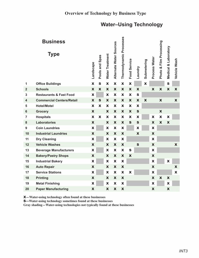
As indicated in the matrix below, thirteen water using technologies have been applied to twenty different business types in this guidebook. Obviously, much of the technology addressed in the guidebook can also be applied to other business types not specifically addressed herein. For example, restroom fixtures, heating and cooling systems, and landscape technologies can also apply to most business types. Each business type has a summary fact sheet followed by a more detailed discussion of the typical end uses by that business. Each fact sheet includes a discussion of the end uses of water, a listing of suggested technologies, and the estimated life-cycle water savings, costs, and payback (cost-effectiveness) of the technology. It is important to note that these water-saving technologies are just suggestions. Each water provider or planning agency can decide what technolo-gies to employ if and when a plan-review program is adopted.
End uses of water are described for each of the twenty business types, along with applicable water-saving technologies, which are grouped into two categories: “Proven Practices for Superior Performance” and “Additional Practices That Achieve Significant Savings.” The technologies in the first category represent, based upon the judgment of the project consultants and the Project Advisory Committee (PAC), “proven” technologies that have demonstrated water savings and represent cost-effective practices for the business. Examples include high-ef-ficiency toilets, pre-rinse spray valves, and connectionless food steamers. Tech-
Introduction
INT2
nologies in the second category have not been extensively field tested for water savings and life-cycle cost-effectiveness, but may reflect new, cutting-edge technologies or provide hints, tips, or innovative applications that may not be common in everyday practice.
The guidebook also includes information on landscape water-use efficiency, since outdoor use is an important issue in many areas and may represent a considerable percent of the water use for any given business. Landscape standards can be developed using either a water budget or checklist approach or a combination of these. It remains up to the water provider to decide what standards to adopt and in what form. For example, a water provider may choose to adopt a checklist approach as a requirement in the plan-review process or simply choose to use the checklist as a guideline that is passed on to a developer.
It was also decided to include information on such alternative water sources as reclamation, gray water, cisterns, etc., for completeness. Each water provider can choose if and how to use that information in their plan-review process.
If a new construction plan review program is desired, an extremely important issue is that of program implementation. Thus, information is presented in the first chapter on the typical plan review process of a planning agency. For a plan review process to work, appropriate resources need to be allocated to the program and communication is needed between a planning entity and the water provider. It is the re-sponsibility of the water provider to ensure their agency’s participation in the plan review process.
Disclaimer These Guidelines are provided exclusively for general education and informational purposes and as a public service by the East Bay Municipal Utility District (EB-MUD). You are authorized to view these Guidelines for your use and to copy any part of them. In exchange for this authorization: (i) you agree not to sell or publish the Guidelines without first receiving written permission from EBMUD; and (ii) you waive, release and covenant not to sue EBMUD and all others affiliated with devel-oping these Guidelines from any liability, claims and actions, both known and un-known, for any losses, damage or equitable relief you may now have a right to assert or later acquire, arising from such use or reliance on the Guidelines. Unauthorized use of these Guidelines is prohibited and a violation of copyright, trademark and other laws. Nothing in these Guidelines constitutes an endorsement, approval, or recommendation of any kind by any persons or organizations affiliated with devel-oping these Guidelines. The suitability and applicability of this information for a given use depends on various factors specific to that use. These include, but are not limited to, laws and regulations applicable to the intended use, specific attributes of that use, and the specifications for any product or material associated with this information. All warranties, express or implied, are disclaimed, and the reader is strongly encouraged to consult with a building, product and/or design professional before applying any of this information to a specific use or purpose.
INT3
Overview of Technology by Business Type
Business
Type
Water–Using Technology
Lan
dsc
ape
Po
ols
an
d S
pas
Wat
er T
reat
men
t
Alt
ern
ate
Wat
er S
ou
rces
Th
erm
od
ynam
ic P
roce
sses
Fo
od
Ser
vice
Lau
nd
ry
Su
bm
eter
ing
Pro
cess
Wat
er
Ph
oto
& F
ilm P
roce
ssin
g
Med
ical
& L
abo
rato
ry
Veh
icle
Was
h
1 Office Buildings X S X X X X X S
2 Schools X X X X X X X X X X X
3 Restaurants & Fast Food X X X X X S
4 Commercial Centers/Retail X S X X X X X X X X
5 Hotel/Motel X X X X X X X
6 Grocery X X X X X S X
7 Hospitals X X X X X X X X X X
8 Laboratories X X X X S S X X X
9 Coin Laundries X X X X X X
10 Industrial Laundries X X X X X X
11 Dry Cleaning X X X X X
12 Vehicle Washes X X X X S X X
13 Beverage Manufacturers X X X X S X
14 Bakery/Pastry Shops X X X X X X
15 Industrial Bakery X X X X X X
16 Auto Repair X X X X X X
17 Service Stations X X X X X X X
18 Printing X X X X X X X
19 Metal Finishing X X X X X X
20 Paper Manufacturing X X X X X X X—Water-using technology often found at these businessesS—Water-using technology sometimes found at these businessesGray shading—Water-using technologies not typically found at these businesses

INT4
This page intentionally left blank.
PRAP1
A water provider may want to adopt water-use efficiency standards and review a developer’s plans to either require and/or recommend water-saving hardware and processes as part of planning, construction, and permitting. The goal in requiring such a review is to improve community water-use efficiency and to reduce devel-oper/owner long-term costs for water, sewer, energy, and, if appropriate, on-site wastewater-treatment facilities. A plan review program for water- (and energy-) use efficiency can thus present a win-win scenario for both the developer and the community through more efficient use of resources.
An important part of the planning and permitting process is developer notifica-tion of requirements for project approval and ultimate occupancy. Projects are reviewed for numerous provisions that include design standards, environmental impacts, and regulatory requirements. The review process requires communica-tion between a planning agency and the other project stakeholders, such as other regulatory agencies. The goal is to allow other stakeholders the opportunity to comment on the project and to notify the developer early in the planning and per-mitting process of a project’s permit conditions. Since a developer’s first contact in the project approval process is typically with a planning agency, the water util-ity, as a potential stakeholder, should strive to be included in a planning agency’s design review and/or permitting process.
The plan review and permitting process varies somewhat among planning agen-cies, but the basic process is similar. Many planning agencies typically forward developer plans to the local water utility for review and comment. However, this practice appears to vary among planning agencies, so the utility needs to verify the plan review process with each planning agency in its service area. The time from a developer’s initial contact with a planning agency to building occupancy varies widely from project to project, but can often take two to three years or more.
Planning-Agency Plan-Review Process (Phase 1)Basically, a plan for a new facility goes through either or both a Tentative Map Plan (TMP) Review or a Design Review. If the project involves a new subdivi-sion, then a review of the Tentative Map Plan is often the first step in the planning process. If not, the first step in the planning process is usually a Development or Design Review. At this point, the plans are sent to other stakeholders for review and comments. These stakeholders may include such agencies as water and waste-water, fire service, air- and water-quality resources, and health departments. The stakeholders provide comments to the planning agency along with their require-ments. The planning agency then determines the appropriate level of environmen-tal review, if any. The developer then addresses project requirements and submits a draft Environmental Impact Report (EIR) to the planning agency which, in turn, forwards it to the various stakeholders for further review. These requirements then
Water-Provider and Planning- Agency New Construction Plan- Review and Approval Process
PRAP2
become part of the permitting process, which ultimately leads to a certificate of occupancy if all permit-ting conditions are met.
The Construction/Permitting Process (Phase 2)The other opportunity to interact with a planning agency occurs in the construction phase of a project and involves building/inspection departments which issue building permits and inspect the construction site for compliance with permit conditions. The water utility could request that one of the permitting conditions be utility approval for water-use efficiency and would entail both plan review and site inspec-tion. This request may or may not be granted by the planning agency, which would probably want some assurances that utility-plan reviews (and site inspections) not delay the normal project schedule. The water utility may want to offer or may be asked to supply “sign-off” stamps signaling approval by the water utility in meeting utility-permit conditions. An ideal goal for the water provider, to ensure compli-ance, is to be included in both the planning and permitting processes.
The Water-Utility Application-for-Service ProcessMost water utilities will not issue a water meter until the conditions for water service are met. So, an obvious first step for the water provider is to develop and adopt water-efficiency standards as a condition for water service. Once efficiency standards are adopted, a top priority should be developer notifica-tion of these requirements as early in the planning process as possible. Since a developer does not often contact the local water utility until much later (months and even years) in the planning process, it is important to develop a working relationship with the local planning agency and to integrate the need for a utility-plan review into their planning process. Doing so may avoid problems for both the developer and the water utility. For a water meter to be issued, a “sign-off” by various departments within a utility is usually needed.
The primary objective of the water-utility application process is to determine conditions for service and an assessment of fees. Fees, in turn, are usually dependent upon water-meter size and facilities (main extensions, storage, pumping, etc.) needed to serve the new development. Thus, a review of a developer’s plans for water-use efficiency may save the developer money, if water demand (meter size) can be reduced.
An important goal of the water utility should be to cooperate with a planning agency in notifying the de-veloper of the utility’s requirements. Developer notification of any utility requirements can occur at ei-ther the planning or permitting point in the project or both. Water-utility representatives should be prepared to undertake a number of measures to increase successful program implementation, including: preparing and sending pertinent material to the planning agency, making presentations to the planning agency, providing site inspections to verify compliance, and providing map stamps for utility sign-off (approval).
S1
Contents:Business TypesOffice Buildings . . . . . . . . . . . . . . . . . . . . . . . . . . . . . . . . . . . . . . . . . . . . S1
Schools . . . . . . . . . . . . . . . . . . . . . . . . . . . . . . . . . . . . . . . . . . . . . . . . . . . S3
Restaurants and Fast-Food Outlets . . . . . . . . . . . . . . . . . . . . . . . . . . . . . . S5
Commercial and Retail Centers . . . . . . . . . . . . . . . . . . . . . . . . . . . . . . . . S7
Hotels and Motels . . . . . . . . . . . . . . . . . . . . . . . . . . . . . . . . . . . . . . . . . . . S9
Grocers . . . . . . . . . . . . . . . . . . . . . . . . . . . . . . . . . . . . . . . . . . . . . . . . . . S11
Hospitals . . . . . . . . . . . . . . . . . . . . . . . . . . . . . . . . . . . . . . . . . . . . . . . . . S13
Laboratories . . . . . . . . . . . . . . . . . . . . . . . . . . . . . . . . . . . . . . . . . . . . . . S15
Coin- and Card-Operated Laundries. . . . . . . . . . . . . . . . . . . . . . . . . . . . S17
Industrial Laundries . . . . . . . . . . . . . . . . . . . . . . . . . . . . . . . . . . . . . . . . S19
Dry Cleaners . . . . . . . . . . . . . . . . . . . . . . . . . . . . . . . . . . . . . . . . . . . . . . S21
Vehicle Washes . . . . . . . . . . . . . . . . . . . . . . . . . . . . . . . . . . . . . . . . . . . . S23
Beverage Manufacturers . . . . . . . . . . . . . . . . . . . . . . . . . . . . . . . . . . . . . S25
Bakery/Pastry Shops . . . . . . . . . . . . . . . . . . . . . . . . . . . . . . . . . . . . . . . . S27
Industrial Bakeries . . . . . . . . . . . . . . . . . . . . . . . . . . . . . . . . . . . . . . . . . S29
Auto Service and Repair Shops . . . . . . . . . . . . . . . . . . . . . . . . . . . . . . . S31
Fuel Service Stations and Convenience Stores. . . . . . . . . . . . . . . . . . . . S33
Commercial Printers . . . . . . . . . . . . . . . . . . . . . . . . . . . . . . . . . . . . . . . . S35
Metal Finishers . . . . . . . . . . . . . . . . . . . . . . . . . . . . . . . . . . . . . . . . . . . . S37
Paper Manufacturers . . . . . . . . . . . . . . . . . . . . . . . . . . . . . . . . . . . . . . . . S39
Water Features, Pool, and Landscapes . . . . . . . . . . . . . . . . . . . . . . . . . . S41
S2
Order of Water-Using Technology Sections in the Guidebook
Restrooms and Plumbing . . . . . . . . . . . . . . . . . RPPools, Spas, and Fountains . . . . . . . . . . . . . . . . PSFWater Treatment . . . . . . . . . . . . . . . . . . . . . . . . WTAlternate On-Site Water Sources . . . . . . . . . . . AOWSThermodynamic Processes . . . . . . . . . . . . . . . . TPFood-Service Operations . . . . . . . . . . . . . . . . . FSOLaundries and Dry-Cleaning Operations . . . . . LDCMetering of Individual Units . . . . . . . . . . . . . . MIUProcess Water . . . . . . . . . . . . . . . . . . . . . . . . . . PWPhoto and Film Processing . . . . . . . . . . . . . . . . PFPMedical Facilities and Laboratories . . . . . . . . . MFLVehicle Washes . . . . . . . . . . . . . . . . . . . . . . . . . VWLandscape Water-Use Efficiency . . . . . . . . . . . LWUE
Key to Water-Using Technology Section Abbreviations Used in the Business-Type Summaries
AOWS. . . Alternate On-Site Water SourcesFSO . . . . . Food-Service OperationsLDC. . . . . Laundries and Dry-Cleaning OperationsLWUE . . . Landscape Water-Use EfficiencyMFL . . . . Medical Facilities and LaboratoriesMIU . . . . . Metering of Individual UnitsPFP . . . . . Photo and Film ProcessingPSF . . . . . Pools, Spas, and FountainsPW. . . . . . Process WaterRP . . . . . . Restrooms and PlumbingTP . . . . . . Thermodynamic ProcessesVW . . . . . Vehicle WashesWT . . . . . Water Treatment
NOTE: In order to keep this Guidebook up-to-date, and to facilitate adding new materials and new sec-tions as they become available, without reproducing the entire Guidebook, the units have been individu-ally numbered, rather than numbering the entire Guidebook sequentially.
S3
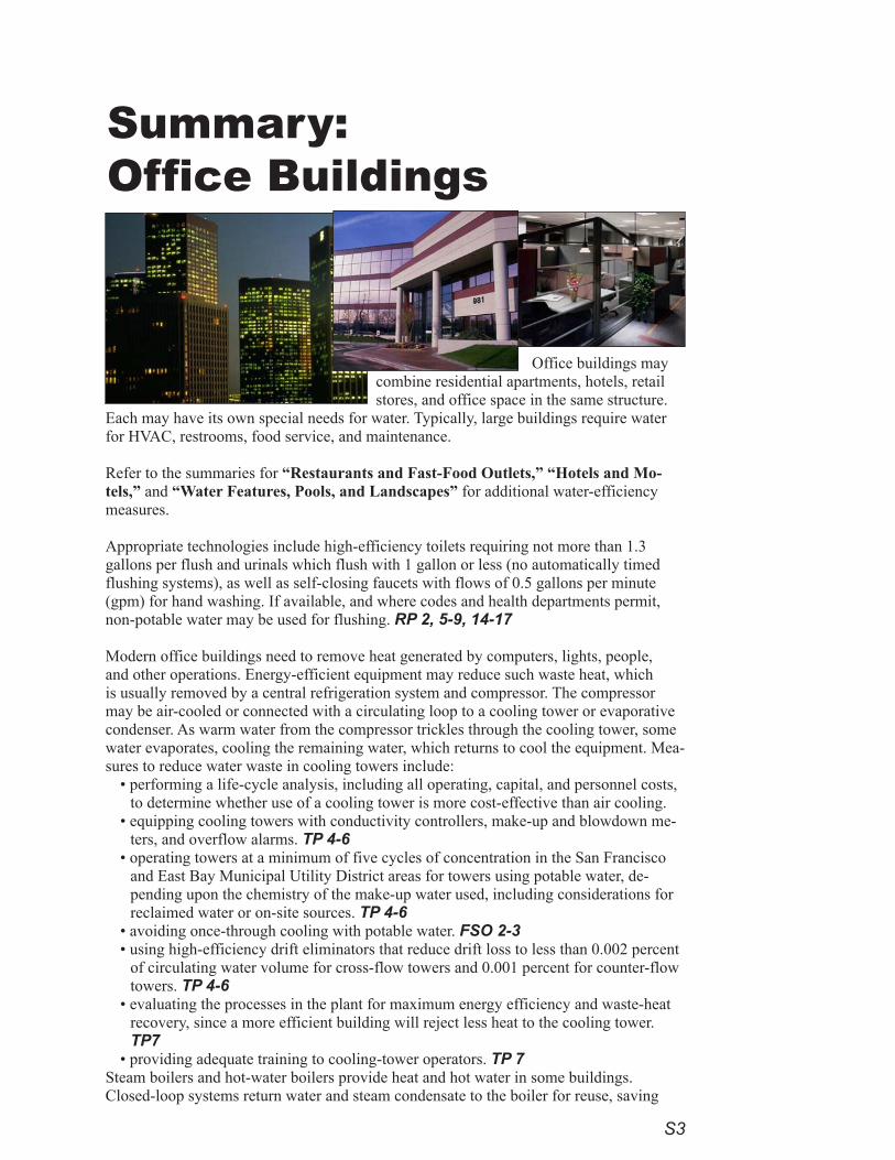
Office buildings may combine residential apartments, hotels, retail stores, and office space in the same structure.
Each may have its own special needs for water. Typically, large buildings require water for HVAC, restrooms, food service, and maintenance.
Refer to the summaries for “Restaurants and Fast-Food Outlets,” “Hotels and Mo-tels,” and “Water Features, Pools, and Landscapes” for additional water-efficiency measures.
Appropriate technologies include high-efficiency toilets requiring not more than 1.3 gallons per flush and urinals which flush with 1 gallon or less (no automatically timed flushing systems), as well as self-closing faucets with flows of 0.5 gallons per minute (gpm) for hand washing. If available, and where codes and health departments permit, non-potable water may be used for flushing. RP 2, 5-9, 14-17
Modern office buildings need to remove heat generated by computers, lights, people, and other operations. Energy-efficient equipment may reduce such waste heat, which is usually removed by a central refrigeration system and compressor. The compressor may be air-cooled or connected with a circulating loop to a cooling tower or evaporative condenser. As warm water from the compressor trickles through the cooling tower, some water evaporates, cooling the remaining water, which returns to cool the equipment. Mea-sures to reduce water waste in cooling towers include:
• performing a life-cycle analysis, including all operating, capital, and personnel costs, to determine whether use of a cooling tower is more cost-effective than air cooling.
• equipping cooling towers with conductivity controllers, make-up and blowdown me-ters, and overflow alarms. TP 4-6
• operating towers at a minimum of five cycles of concentration in the San Francisco and East Bay Municipal Utility District areas for towers using potable water, de-pending upon the chemistry of the make-up water used, including considerations for reclaimed water or on-site sources. TP 4-6
• avoiding once-through cooling with potable water. FSO 2-3• using high-efficiency drift eliminators that reduce drift loss to less than 0.002 percent
of circulating water volume for cross-flow towers and 0.001 percent for counter-flow towers. TP 4-6
• evaluating the processes in the plant for maximum energy efficiency and waste-heat recovery, since a more efficient building will reject less heat to the cooling tower. TP7
• providing adequate training to cooling-tower operators. TP 7Steam boilers and hot-water boilers provide heat and hot water in some buildings. Closed-loop systems return water and steam condensate to the boiler for reuse, saving
Summary: Office Buildings
S4
energy and water. Open-loop systems expend the water or steam without return to the boiler. Several water-effi-ciency choices are available:
•recirculating hot-water systems for large buildings. RP 7-8•steam boilers of 200 boiler horsepower (hp) or greater, equipped with conductivity controllers to regulate top
blowdown. TP7-8, 10 •for closed-loop systems, condensate-return meters on steam boilers of 200 boiler hp or greater. TP7-8, 10•closed-loop steam systems operating at twenty cycles of concentration or greater (5 percent or less of makeup
water). TP 10•steam-distribution lines and equipment with steam traps meeting all codes.•make-up meters on feed-water lines:
to steam boilers and water boilers of more than 100,000 Btus per hour. TP 8-10to closed-loop hot-water systems for heating. TP 9-10
• boiler-temperature and make-up meters that are clearly visible to operators. TP 11•discharge pipes that are easy to inspect for flow and visible indicators that will indicate whether the valve has
activated, thereby reducing plumbing leaks due to repeated openings of water-temperature- and pressure-relief valves (TPRVs). RP3, 21
Measures to improve the efficiency of water treatment include:•for all filtration processes, installing pressure gauges to determine when to backwash or change cartridges,
followed by backwash based upon pressure differential. WT 5•for all ion-exchange and softening processes, setting recharge cycles by volume of water treated or using con-
ductivity controllers. WT 5•avoiding the use of timers for softener-recharge systems. WT 5•using water treatment only when necessary. WT 5
Other recommendations include:• installing automatic shutoff and solenoid valves on all hoses and water-using equipment. PW 7• installing faucets on set tubs and janitorial sinks with flows not to exceed 2.2 gpm. RP3, 14-17• conspicuously marking fire-protection plumbing so no connections will be made other than those for fire pro-
tection and installing flow-detection meters on fire services to reveal unauthorized water flows. RP4, 23
Floor-cleaning efficiency measures include: • low-flow, high-pressure nozzles on hoses or water brooms for floor and mat washing where a flow of water is
needed. RP2, 19, FSP18-20, PW 5, 7• drains placed close to areas where liquid discharges are expected in order to minimize the need to use a hose
as a broom. PW 5, 7
Ice machines use water for ice and sometimes for cooling the compressor. Select: • ice-making machines that are air-cooled, using remote heads to expel warm air outside the work space and
customer areas. Air-cooled machines are preferred over cooling-tower loops. • energy-efficient flake or nugget machines rather than cube-ice machines. If cube-ice machines are used, those
that meet CEE Tier 2 efficiency standards are preferred. Tier 3 machines are even more efficient (CEE Com-mercial Kitchens). FSO 3-4
Submetering — separate metering of individual units (tenants), water-using systems, or building areas — is rec-ommended where possible in order to ensure that the costs of water use and, where feasible, wastewater disposal are equitably dispersed and accounted for accurately. Reflecting actual use and costs often offers a reliable incen-tive for water-use efficiency. MIU
»»
S�
Summary: Schools
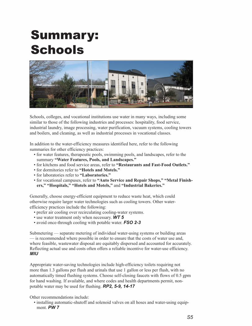
Schools, colleges, and vocational institutions use water in many ways, including some similar to those of the following industries and processes: hospitality, food service, industrial laundry, image processing, water purification, vacuum systems, cooling towers and boilers, and cleaning, as well as industrial processes in vocational classes.
In addition to the water-efficiency measures identified here, refer to the following summaries for other efficiency practices:
• for water features, therapeutic pools, swimming pools, and landscapes, refer to the summary “Water Features, Pools, and Landscapes.”
• for kitchens and food service areas, refer to “Restaurants and Fast-Food Outlets.” • for dormitories refer to “Hotels and Motels.”• for laboratories refer to “Laboratories.”• for vocational campuses, refer to “Auto Service and Repair Shops,” “Metal Finish-
ers,” “Hospitals,” “Hotels and Motels,” and “Industrial Bakeries.”
Generally, choose energy-efficient equipment to reduce waste heat, which could otherwise require larger water technologies such as cooling towers. Other water-efficiency practices include the following:
• prefer air cooling over recirculating cooling-water systems. • use water treatment only when necessary. WT 5 • avoid once-through cooling with potable water. FSO 2-3
Submetering — separate metering of individual water-using systems or building areas — is recommended where possible in order to ensure that the costs of water use and, where feasible, wastewater disposal are equitably dispersed and accounted for accurately. Reflecting actual use and costs often offers a reliable incentive for water-use efficiency. MIU
Appropriate water-saving technologies include high-efficiency toilets requiring not more than 1.3 gallons per flush and urinals that use 1 gallon or less per flush, with no automatically timed flushing systems. Choose self-closing faucets with flows of 0.5 gpm for hand washing. If available, and where codes and health departments permit, non-potable water may be used for flushing. RP2, 5-9, 14-17
Other recommendations include:• installing automatic-shutoff and solenoid valves on all hoses and water-using equip-
ment. PW 7
S6
• installing faucets on set tubs and janitorial sinks, with flows not to exceed 2.2 gpm. RP3, 14-17• conspicuously marking fire-protection plumbing so no connections will be made other than those for fire pro-
tection and installing flow-detection meters on fire services to reveal unauthorized water flows. RP4,23
Cooling-towers may be required for some facilities. If their need is determined, numerous operational efficiency measures may be employed:
• Conduct a life-cycle analysis, including all operating, capital, and personnel costs, to determine whether the use of a cooling tower is more cost-effective than air cooling.
• Equip all cooling towers with conductivity controllers, make-up and blowdown meters, and overflow alarms. TP 4-6
• Operate towers at a minimum of five cycles of concentration in the San Francisco and East Bay Municipal Utility District areas for towers using potable water, depending upon the chemistry of the make-up water, including considerations for reclaimed water or on-site sources. TP 4-6
• Install high-efficiency drift eliminators that reduce drift loss to less than 0.002 percent of circulating water volume for cross-flow towers and 0.001 percent for counter-flow towers. TP 4-6
• Avoid using cooling towers of less than 100 tons for air-conditioning systems. TP 7• Evaluate entire buildings or processes for maximum energy efficiency, since more efficient buildings will
reject less heat to cooling towers. TP 7• Evaluate waste-heat recovery for beneficial uses rather than rejecting it to the tower. TP 7
Steam boilers and hot-water boilers provide heat and hot water in some buildings. Closed-loop systems return water and steam condensate to the boiler for reuse, saving energy and water. Open-loop systems expend the water or steam without return to the boiler. Several water-efficiency measures are available:
•Equip steam boilers of 200 boiler-horsepower (hp) or greater with conductivity controllers to regulate top blowdown. TP7-8, 10
•Install condensate-return meters on closed-loop-system steam boilers of 200 boiler hp or greater. TP7-8, 10•Design closed-loop steam systems to operate at twenty cycles of concentration or greater (5 percent or less of
make-up water). TP 10•Equip steam-distribution lines and equipment with steam traps meeting all codes.•Install make-up meters on feed-water lines to:
steam boilers and water boilers of more than 100,000 Btus per hour. TP 8-10closed-loop hot-water systems for heating. TP 9-10make sure boiler-temperature and make-up meters are clearly visible to operators. TP 11make discharge pipes easy to inspect for flow, and incorporate visible indicators that will reveal whether the valve has been activated. RP3, 21
Wet methods may be used for floor cleaning, but open hoses are discouraged as being wasteful. To increase water-use efficienccy:
•install drains close to areas where liquid discharges are expected. PW 5, 7•arrange equipment for easy use of mop and squeegee systems or floor-cleaning machines. •install self-closing nozzles, limiting flow of washdown hoses to 5 gpm.
For laboratories, choose dry-vacuum systems rather than liquid-ring pumps. For vacuum and compressor systems, use air-cooled, radiator-cooled, or chilled-loop or cooling-tower systems. MLF2-3, 8
For photography and medical and other imaging, employ digital technologies that allow images to be displayed on electronic video screens and stored in computer files. Where film imaging is required, use self-contained “mini-lab” developing units that require no plumbing or washing to develop the film. For paper or film image copies use laser or ink-jet printing. PFP 5-8
Photos:Catherine Putsche
»»»»
S7
Summary: Restaurants and Fast-Food Outlets
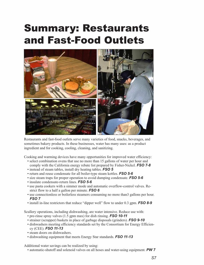
Restaurants and fast-food outlets serve many varieties of food, snacks, beverages, and sometimes bakery products. In these businesses, water has many uses: as a product ingredient and for cooking, cooling, cleaning, and sanitizing.
Cooking and warming devices have many opportunities for improved water efficiency: • select combination ovens that use no more than 15 gallons of water per hour and
comply with the California energy rebate list prepared by Fisher-Nickel. FSO 7-8• instead of steam tables, install dry heating tables. FSO 5• return and reuse condensate for all boiler-type steam kettles. FSO 5-6• size steam traps for proper operation to avoid dumping condensate. FSO 5-6• insulate condensate-return lines. FSO 5-6• use pasta cookers with a simmer mode and automatic overflow-control valves. Re-
strict flow to a half a gallon per minute. FSO 6• use connectionless or boilerless steamers consuming no more than3 gallons per hour.
FSO 7• install in-line restrictors that reduce “dipper well” flow to under 0.3 gpm. FSO 8-9
Scullery operations, including dishwashing, are water intensive. Reduce use with:• pre-rinse spray valves (1.5 gpm max) for dish rinsing. FSO 10-11 • strainer (scrapper) baskets in place of garbage disposals (grinders). FSO 9-10• dishwashers meeting efficiency standards set by the Consortium for Energy Efficien-
cy (CEE). FSO 11-13• steam doors on dishwashers.• dishwashing equipment that meets Energy Star standards. FSO 11-13
Additional water savings can be realized by using:• automatic-shutoff and solenoid valves on all hoses and water-using equipment. PW 7
S8
• faucets on set tubs and janitorial sinks with flows not exceeding 2.2 gpm. RP3, 14-17 Floor cleaning may use wet methods, but wasteful open hoses are discouraged. Install drains close to areas where liquid discharges are expected. Arrange equipment for easy use of a mop and squeegee system or floor-cleaning machine. Install self-closing nozzles, limiting flow to 5 gpm on washdown hoses.
Appropriate technologies include high-efficiency toilets requiring not more than 1.3 gallons per flush and urinals which flush with 1 gallon or less (no automatically timed flushing systems), as well as self-closing faucets with flows of 0.5 gallons per minute (gpm) for hand washing. If available, and where codes and health departments permit, non-potable water may be used for flushing. RP 2, 5-9, 14-17
Conspicuously mark fire-protection plumbing so no connections will be made except for fire protection. Addition-ally, flow-detection meters should be installed on fire services to signal unauthorized water flows. RP4
Submetering — separate metering of individual units, water-using systems, or building areas — is recommended where possible in order to ensure that the costs of water use and, where feasible, wastewater disposal are equitably dispersed and accounted for accurately. Reflecting actual use and costs often offers a reliable incentive for water-use efficiency. MIU
Refer to the “Office Buildings” and “Schools” summaries for recommendations on evaluating cooling towers versus air-cooling, open- versus closed-loop systems, and heat and hot-water system practicies.
Refer to the summaries for “Bakery/Pastry Shops,” “Industrial Bakeries,” and “Water Features, Pools, and Landscapes” for additional water-efficiency measures specific to restaurant and food-service businesses.
Selecting energy-efficient equipment helps reduce waste heat, which has implications for water use. Because of particular practices in the restaurant and food-service business, energy-efficient equipment offers significant water savings. Choose refrigerators and freezers that have adequate refrigerator space for thawing food and use air-cooling rather than recirculating cooling-water systems. FSO 2-3
Ice machines use water for ice and sometimes for cooling the compressor. Select: • ice-making machines that are air-cooled, using remote heads to expel warm air outside the work space and
customer areas. Air-cooled machines are preferred over a cooling-tower loop. • energy-efficient flake or nugget machines rather than cube machines. If cube-ice machines are used, select
those that meet Energy Star standards. CEE Tier 3 machines are even more efficient. FSO 3-4
Measures to improve the efficiency of water treatment include:• for all filtration processes, install pressure gauges to determine when to backwash or change cartridges, then
backwash based upon pressure differential. WT 5• for all ion-exchange and softening processes, set recharge cycles by volume of water treated or based upon
conductivity controllers. WT 5• avoid the use of timers for softener recharge systems. WT 5
S9
Summary: Commercial and Retail Centers
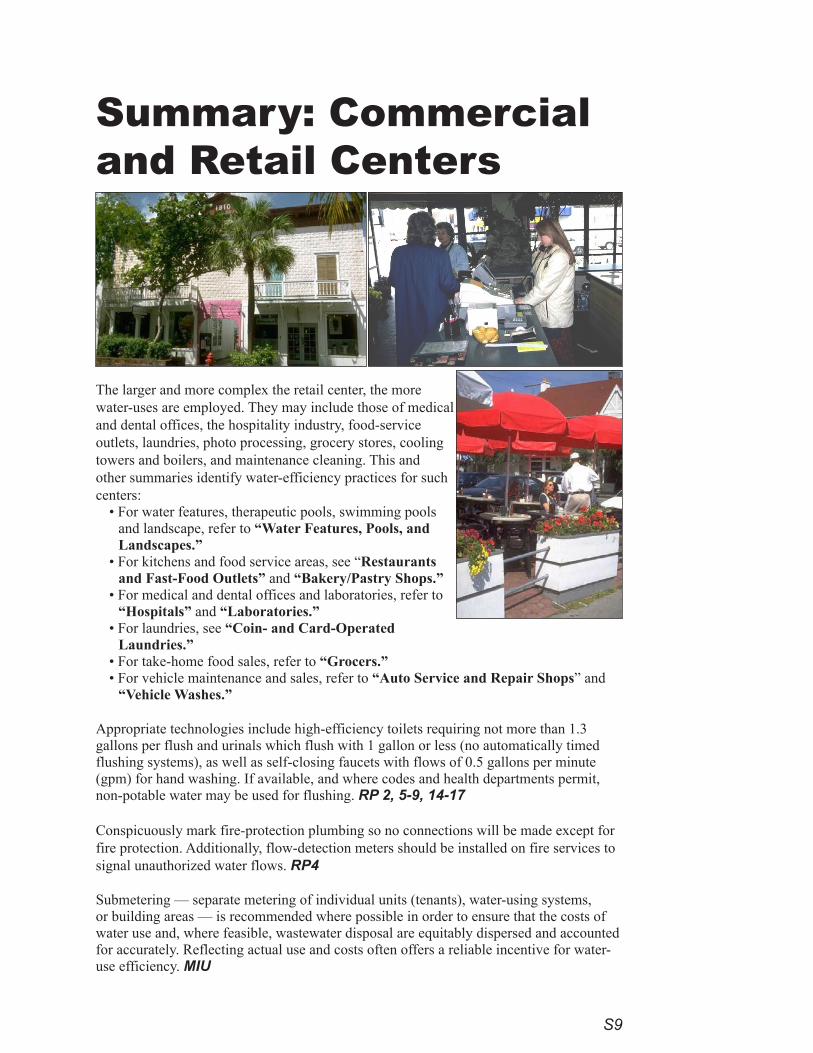
The larger and more complex the retail center, the more water-uses are employed. They may include those of medical and dental offices, the hospitality industry, food-service outlets, laundries, photo processing, grocery stores, cooling towers and boilers, and maintenance cleaning. This and other summaries identify water-efficiency practices for such centers:
• For water features, therapeutic pools, swimming pools and landscape, refer to “Water Features, Pools, and Landscapes.”
• For kitchens and food service areas, see “Restaurants and Fast-Food Outlets” and “Bakery/Pastry Shops.”
• For medical and dental offices and laboratories, refer to “Hospitals” and “Laboratories.”
• For laundries, see “Coin- and Card-Operated Laundries.”
• For take-home food sales, refer to “Grocers.”• For vehicle maintenance and sales, refer to “Auto Service and Repair Shops” and
“Vehicle Washes.”
Appropriate technologies include high-efficiency toilets requiring not more than 1.3 gallons per flush and urinals which flush with 1 gallon or less (no automatically timed flushing systems), as well as self-closing faucets with flows of 0.5 gallons per minute (gpm) for hand washing. If available, and where codes and health departments permit, non-potable water may be used for flushing. RP 2, 5-9, 14-17
Conspicuously mark fire-protection plumbing so no connections will be made except for fire protection. Additionally, flow-detection meters should be installed on fire services to signal unauthorized water flows. RP4
Submetering — separate metering of individual units (tenants), water-using systems, or building areas — is recommended where possible in order to ensure that the costs of water use and, where feasible, wastewater disposal are equitably dispersed and accounted for accurately. Reflecting actual use and costs often offers a reliable incentive for water-use efficiency. MIU

S10
Floor cleaning may use wet methods, but wasteful open hoses are discouraged. Install drains close to areas where liquid discharges are expected. Arrange equipment for easy use of a mop and squeegee system or floor-cleaning machine. Install self-closing nozzles, limiting flow to 5 gpm on washdown hoses.
Refer to the “Office Buildings” and “Schools” summaries for recommendations on evaluating cooling towers versus air-cooling, open- versus closed-loop systems, and heat and hot-water system practicies.
For photography and medical and other imaging, employ digital technologies that allow images to be displayed on electronic video screens and stored on computer files. Where film imaging is required, use self-contained “mini-lab” image-developing units that require no plumbing or washing to develop the film. For paper or film copies of the image, produce images using laser or ink-jet printing technology. PFP 5-8
S11
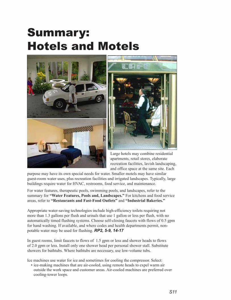
Large hotels may combine residential apartments, retail stores, elaborate recreation facilities, lavish landscaping, and office space at the same site. Each
purpose may have its own special needs for water. Smaller motels may have similar guest-room water uses, plus recreation facilities and irrigated landscapes. Typically, large buildings require water for HVAC, restrooms, food service, and maintenance.
For water features, therapeutic pools, swimming pools, and landscapes, refer to the summary for “Water Features, Pools and, Landscapes.” For kitchens and food service areas, refer to “Restaurants and Fast-Food Outlets” and “Industrial Bakeries.”
Appropriate water-saving technologies include high-efficiency toilets requiring not more than 1.3 gallons per flush and urinals that use 1 gallon or less per flush, with no automatically timed flushing systems. Choose self-closing faucets with flows of 0.5 gpm for hand washing. If available, and where codes and health departments permit, non-potable water may be used for flushing. RP2, 5-9, 14-17
In guest rooms, limit faucets to flows of 1.5 gpm or less and shower heads to flows of 2.0 gpm or less. Install only one shower head per personal shower stall. Substitute showers for bathtubs. Where bathtubs are necessary, use low-volume tubs.
Ice machines use water for ice and sometimes for cooling the compressor. Select: • ice-making machines that are air-cooled, using remote heads to expel warm air
outside the work space and customer areas. Air-cooled machines are preferred over cooling-tower loops.
Summary: Hotels and Motels
S12
• energy-efficient flake or nugget machines rather than cube-ice machines. If cube-ice machines are used, those that meet CEE Tier 2 efficiency standards are preferred. Tier 3 machines are even more efficient (CEE Com-mercial Kitchens). FSO 3-4
Conspicuously mark fire-protection plumbing so no connections will be made except for fire protection. Addition-ally, flow-detection meters should be installed on fire services to signal unauthorized water flows. RP4
Floor cleaning may use wet methods, but wasteful open hoses are discouraged. Install drains close to areas where liquid discharges are expected. Arrange equipment for easy use of a mop and squeegee system or floor-cleaning machine. Install self-closing nozzles, limiting flow to 5 gpm on washdown hoses.
Submetering — separate metering of individual units, water-using systems, or building areas — is recommended where possible in order to ensure that the costs of water use and, where feasible, wastewater disposal are equitably dispersed and accounted for accurately. Reflecting actual use and costs often offers a reliable incentive for water-use efficiency. MIU
Refer to the “Office Buildings” and “Schools” summaries for recommendations on evaluating cooling towers versus air-cooling, open- versus closed-loop systems, and heat and hot-water system practicies are also discussed in these summaries.
S13
Summary:Grocers
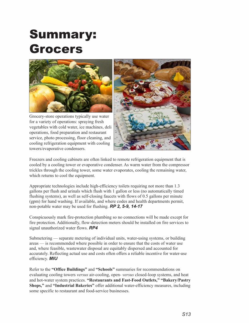
Grocery-store operations typically use water for a variety of operations: spraying fresh vegetables with cold water, ice machines, deli operations, food preparation and restaurant service, photo processing, floor cleaning, and cooling refrigeration equipment with cooling towers/evaporative condensers.
Freezers and cooling cabinets are often linked to remote refrigeration equipment that is cooled by a cooling tower or evaporative condenser. As warm water from the compressor trickles through the cooling tower, some water evaporates, cooling the remaining water, which returns to cool the equipment.
Appropriate technologies include high-efficiency toilets requiring not more than 1.3 gallons per flush and urinals which flush with 1 gallon or less (no automatically timed flushing systems), as well as self-closing faucets with flows of 0.5 gallons per minute (gpm) for hand washing. If available, and where codes and health departments permit, non-potable water may be used for flushing. RP 2, 5-9, 14-17
Conspicuously mark fire-protection plumbing so no connections will be made except for fire protection. Additionally, flow-detection meters should be installed on fire services to signal unauthorized water flows. RP4
Submetering — separate metering of individual units, water-using systems, or building areas — is recommended where possible in order to ensure that the costs of water use and, where feasible, wastewater disposal are equitably dispersed and accounted for accurately. Reflecting actual use and costs often offers a reliable incentive for water-use efficiency. MIU
Refer to the “Office Buildings” and “Schools” summaries for recommendations on evaluating cooling towers versus air-cooling, open- versus closed-loop systems, and heat and hot-water system practices. “Restaurants and Fast-Food Outlets,” “Bakery/Pastry Shops,” and “Industrial Bakeries” offer additional water-efficiency measures, including some specific to restaurant and food-service businesses.

S14
Limit sprays to fresh vegetables to the amount necessary. Additional water savings can be realized by using:• automatic-shutoff and solenoid valves on all hoses and water-using equipment. PW 7• faucets on set tubs and janitorial sinks with flows not exceeding 2.2 gpm. RP3, 14-17
Ice machines use water for ice and sometimes for cooling the compressor. Select: • ice-making machines that are air-cooled, using remote heads to expel warm air outside the work space and
customer areas. Air-cooled machines are preferred over cooling-tower loops. • energy-efficient flake or nugget machines rather than cube-ice machines. If cube-ice machines are used, those
that meet CEE Tier 2 efficiency standards are preferred. Tier 3 machines are even more efficient (CEE Com-mercial Kitchens). FSO 3-4
Floor cleaning may use wet methods, but wasteful open hoses are discouraged. Install drains close to areas where liquid discharges are expected. PW 5, 7 Arrange equipment for easy use of a mop and squeegee system or floor-cleaning machine. Install self-closing nozzles, limiting flow to 5 gpm on washdown hoses.
Photo processing should use self-contained “mini labs” that require no plumbing or washing. PFP 7-8
S1�
Summary:Hospitals
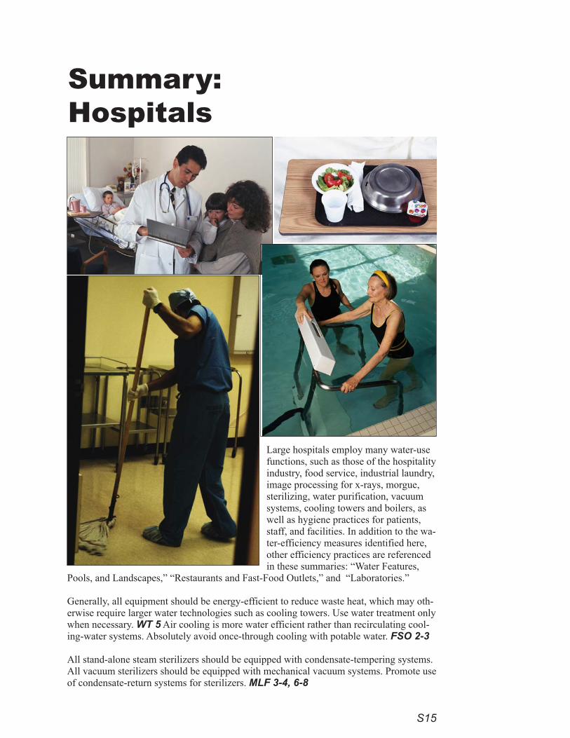
Large hospitals employ many water-use functions, such as those of the hospitality industry, food service, industrial laundry, image processing for x-rays, morgue, sterilizing, water purification, vacuum systems, cooling towers and boilers, as well as hygiene practices for patients, staff, and facilities. In addition to the wa-ter-efficiency measures identified here, other efficiency practices are referenced in these summaries: “Water Features,
Pools, and Landscapes,” “Restaurants and Fast-Food Outlets,” and “Laboratories.”
Generally, all equipment should be energy-efficient to reduce waste heat, which may oth-erwise require larger water technologies such as cooling towers. Use water treatment only when necessary. WT 5 Air cooling is more water efficient rather than recirculating cool-ing-water systems. Absolutely avoid once-through cooling with potable water. FSO 2-3
All stand-alone steam sterilizers should be equipped with condensate-tempering systems. All vacuum sterilizers should be equipped with mechanical vacuum systems. Promote use of condensate-return systems for sterilizers. MLF 3-4, 6-8
S16
For X-rays, MRI, CT scans, and other imaging, employ digital technologies that allow images to be displayed on electronic video screens and stored on computer files. Where film imaging is required, use self-contained “mini-lab” image-developing units that require no plumbing or washing to develop the film. Produce paper or film cop-ies of images using laser or ink-jet printing technology. Where large x-ray film technologies are retained, employ Water Saver/PlusTM recycling technology to vastly reduce water waste. PFP 5-8
Install dry-vacuum systems instead of liquid-ring pumps. All vacuum and compressor systems should be air-cooled or use a radiator cooler or a chilled-loop or cooling-tower system. MLF2-3, 8
Ice machines are located in many places throughout hospitals. Select: • ice-making machines that are air-cooled, using remote heads to expel warm air outside the work space and
customer areas. Air-cooled machines are preferred over cooling-tower loops. • energy-efficient flake or nugget machines rather than cube-ice machines. If cube-ice machines are used, those
that meet CEE Tier 2 efficiency standards are preferred. Tier 3 machines are even more efficient (CEE Com-mercial Kitchens). FSO 3-4
Appropriate technologies include high-efficiency toilets requiring not more than 1.3 gallons per flush and urinals which flush with 1 gallon or less (no automatically timed flushing systems), as well as self-closing faucets with flows of 0.5 gallons per minute (gpm) for hand washing. If available, and where codes and health departments permit, non-potable water may be used for flushing. RP 2, 5-9, 14-17
Install automatic-shutoff and solenoid valves on all hoses and water-using equipment. PW 7
Install faucets on set tubs and janitorial sinks with flows not to exceed 2.2 gpm. RP3, 14-17 Floor cleaning may use wet methods, but wasteful open hoses are discouraged. Install drains close to areas where liquid discharges are expected. PW 5, 7 Arrange equipment for easy use of mop and squeegee systems or floor cleaning machines. Install self-closing nozzles, limiting flow to 5 gpm on washdown hoses.
Conspicuously mark fire-protection plumbing so no connections will be made except for fire protection. Addition-ally, flow-detection meters should be installed on fire services to signal unauthorized water flows. RP4
Major water-using systems and building areas should be separately metered. PW 7 Submetering — separate me-tering of individual units, water-using systems, or building areas — helps ensure that the costs of water use and, where feasible, wastewater disposal are equitably dispersed and accounted for accurately. Reflecting actual use and costs often offers a reliable incentive for water-use efficiency. MIU
Refer to the “Office Buildings” and “Schools” summaries for recommendations on evaluating cooling towers versus air-cooling, open- versus closed-loop systems, and heat and hot-water system practices.
S17
Summary:Laboratories
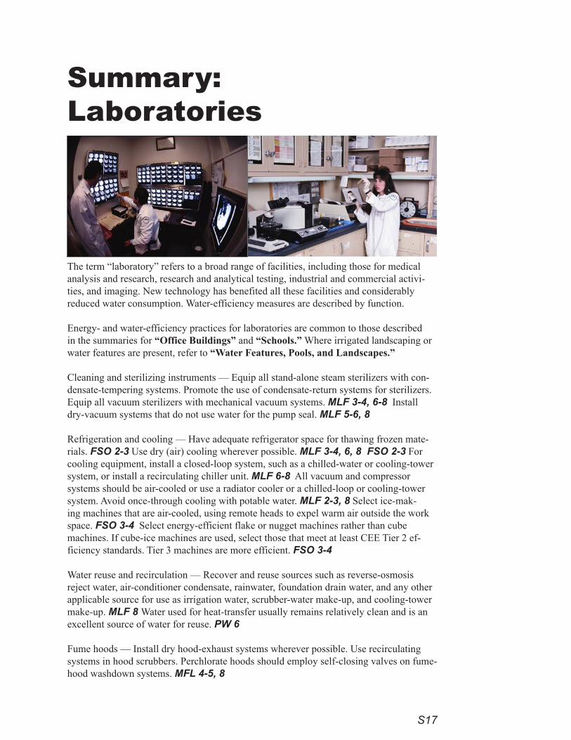
The term “laboratory” refers to a broad range of facilities, including those for medical analysis and research, research and analytical testing, industrial and commercial activi-ties, and imaging. New technology has benefited all these facilities and considerably reduced water consumption. Water-efficiency measures are described by function.
Energy- and water-efficiency practices for laboratories are common to those described in the summaries for “Office Buildings” and “Schools.” Where irrigated landscaping or water features are present, refer to “Water Features, Pools, and Landscapes.”
Cleaning and sterilizing instruments — Equip all stand-alone steam sterilizers with con-densate-tempering systems. Promote the use of condensate-return systems for sterilizers. Equip all vacuum sterilizers with mechanical vacuum systems. MLF 3-4, 6-8 Install dry-vacuum systems that do not use water for the pump seal. MLF 5-6, 8
Refrigeration and cooling — Have adequate refrigerator space for thawing frozen mate-rials. FSO 2-3 Use dry (air) cooling wherever possible. MLF 3-4, 6, 8 FSO 2-3 For cooling equipment, install a closed-loop system, such as a chilled-water or cooling-tower system, or install a recirculating chiller unit. MLF 6-8 All vacuum and compressor systems should be air-cooled or use a radiator cooler or a chilled-loop or cooling-tower system. Avoid once-through cooling with potable water. MLF 2-3, 8 Select ice-mak-ing machines that are air-cooled, using remote heads to expel warm air outside the work space. FSO 3-4 Select energy-efficient flake or nugget machines rather than cube machines. If cube-ice machines are used, select those that meet at least CEE Tier 2 ef-ficiency standards. Tier 3 machines are more efficient. FSO 3-4
Water reuse and recirculation — Recover and reuse sources such as reverse-osmosis reject water, air-conditioner condensate, rainwater, foundation drain water, and any other applicable source for use as irrigation water, scrubber-water make-up, and cooling-tower make-up. MLF 8 Water used for heat-transfer usually remains relatively clean and is an excellent source of water for reuse. PW 6
Fume hoods — Install dry hood-exhaust systems wherever possible. Use recirculating systems in hood scrubbers. Perchlorate hoods should employ self-closing valves on fume-hood washdown systems. MFL 4-5, 8
S18
For X-rays, MRIs, CT scans, and other imaging techniques, employ digital technologies that allow images to be displayed on electronic video screens and stored on computer files. Where film imaging is required, use self-con-tained “mini-lab” image-developing units that require no plumbing or washing to develop the film. For paper or film copies of images, produce them using laser or ink-jet printing technology. Where large x-ray film technolo-gies are retained, Water Saver/PlusTM recycling technology can be employed to vastly reduce water waste. PFP 5-8
Boiler-water efficiency — Closed-loop systems return water and steam condensate to a boiler for reuse, saving energy and water. Open-loop systems expend the water or steam without return to the boiler. Install make-up meters on feed-water lines to steam boilers and water boilers of more than 100,000 Btus per hour and closed-loop hot-water systems for heating. TP 8-10 Situate boiler-temperature and make-up meters to be clearly visible to operators. TP 11 Equip steam boilers of 200 boiler hp or greater with conductivity controllers to regulate top blowdown. TP 7-8, 10 For closed-loop steam systems, install condensate-return meters and operate at twenty cycles of concentration or greater (5 percent or less of make-up water). TP 7-8, 10 Reduce plumbing leaks due to repeated openings of water-tempreature and pressure-relief valves (TPRV’s). Make discharge pipes easy to inspect for flow and ensure that valve activations are visibly indicated. RP 3, 21
Measures to improve water efficiency in water treatment include:• using water treatment only when necessary. • for all filtration processes, install pressure gauges, then backwash or change cartridges based upon pressure
differential. Avoid use of timers for softener recharge systems. • for all ion-exchange and softening processes, set recharge cycles by volume of water treated or based upon
conductivity controllers. • use reverse-osmosis and nanofiltration systems with the lowest reject rate for size. WT 5• if distillation equipment is required, choose equipment that uses air-cooled coils. If water-cooled, the still
should recover at least 85 percent of the feed water. WT 4-5
Install automatic-shutoff and solenoid valves on all hoses and water-using equipment. PW 7
Install faucets on set tubs and janitorial sinks with flows not to exceed 2.2 gpm. RP 3, 14-17 Floor cleaning may use wet methods, but wasteful open hoses are discouraged. Install drains close to areas where liquid discharges are expected. PW 5, 7 Arrange equipment for easy use of mop and squeegee systems or floor-cleaning machines. Install self-closing nozzles, limiting flow to 5 gpm on washdown hoses.
In restrooms use high-efficiency toilets using not more than 1.3 gallons per flush and urinals that use 1 gallon or less per flush, with no automatically timed flushing systems. Choose self-closing hand washing faucets with flows of 0.5 gpm. If available, and where codes and health departments permit, use non-potable water for flushing. RP 2, 5-9, 14-17
Conspicuously mark fire-protection plumbing so no connections will be made except for fire protection. Addition-ally, flow-detection meters should be installed on fire services to signal unauthorized water flows. RP 4
Submetering — separate metering of individual units, water-using systems, or building areas — is recommended where possible in order to ensure that the costs of water use and, where feasible, wastewater disposal are equitably dispersed and accounted for accurately. Reflecting actual use and costs often offers a reliable incentive for water-use efficiency. MIU
S19
Summary: Coin- and Card-Operated Laundries
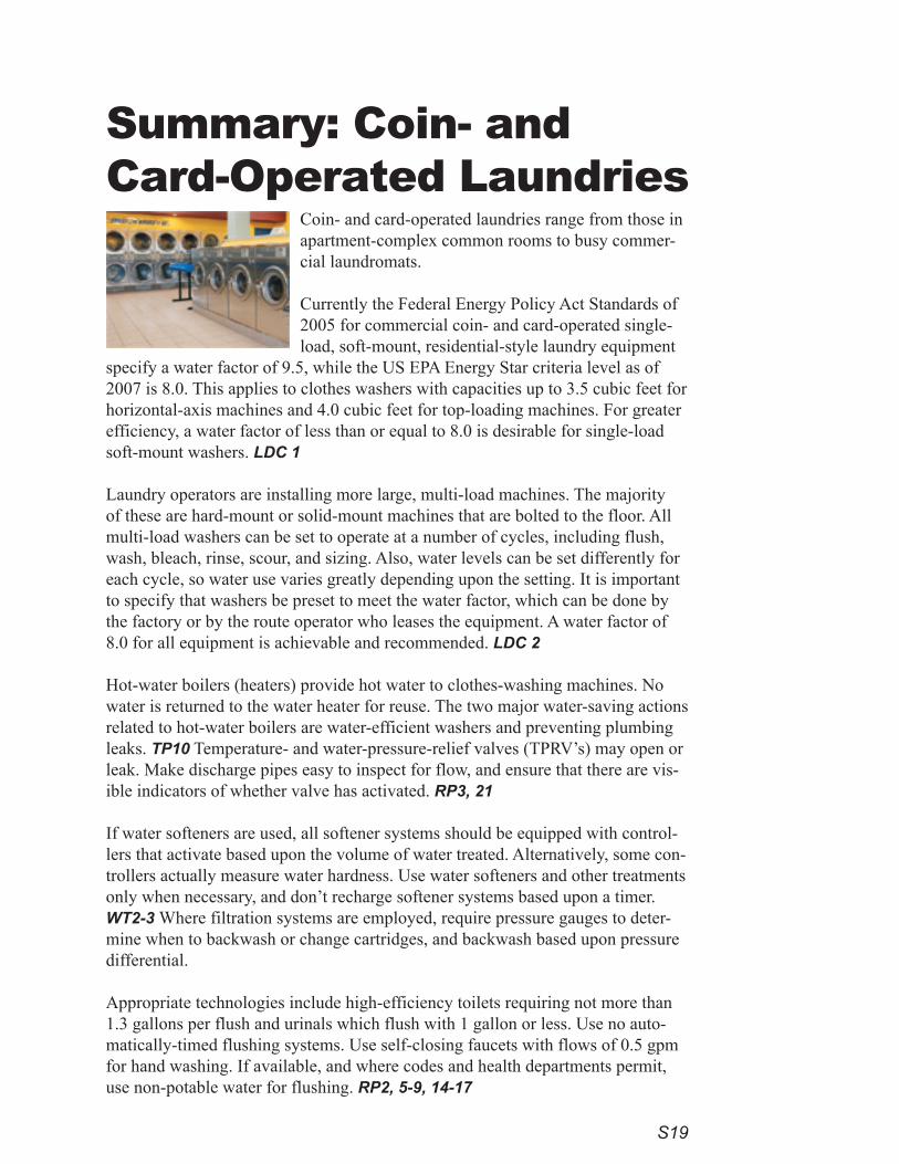
Coin- and card-operated laundries range from those in apartment-complex common rooms to busy commer-cial laundromats.
Currently the Federal Energy Policy Act Standards of 2005 for commercial coin- and card-operated single-load, soft-mount, residential-style laundry equipment
specify a water factor of 9.5, while the US EPA Energy Star criteria level as of 2007 is 8.0. This applies to clothes washers with capacities up to 3.5 cubic feet for horizontal-axis machines and 4.0 cubic feet for top-loading machines. For greater efficiency, a water factor of less than or equal to 8.0 is desirable for single-load soft-mount washers. LDC 1
Laundry operators are installing more large, multi-load machines. The majority of these are hard-mount or solid-mount machines that are bolted to the floor. All multi-load washers can be set to operate at a number of cycles, including flush, wash, bleach, rinse, scour, and sizing. Also, water levels can be set differently for each cycle, so water use varies greatly depending upon the setting. It is important to specify that washers be preset to meet the water factor, which can be done by the factory or by the route operator who leases the equipment. A water factor of 8.0 for all equipment is achievable and recommended. LDC 2
Hot-water boilers (heaters) provide hot water to clothes-washing machines. No water is returned to the water heater for reuse. The two major water-saving actions related to hot-water boilers are water-efficient washers and preventing plumbing leaks. TP10 Temperature- and water-pressure-relief valves (TPRV’s) may open or leak. Make discharge pipes easy to inspect for flow, and ensure that there are vis-ible indicators of whether valve has activated. RP3, 21
If water softeners are used, all softener systems should be equipped with control-lers that activate based upon the volume of water treated. Alternatively, some con-trollers actually measure water hardness. Use water softeners and other treatments only when necessary, and don’t recharge softener systems based upon a timer. WT2-3 Where filtration systems are employed, require pressure gauges to deter-mine when to backwash or change cartridges, and backwash based upon pressure differential. Appropriate technologies include high-efficiency toilets requiring not more than 1.3 gallons per flush and urinals which flush with 1 gallon or less. Use no auto-matically-timed flushing systems. Use self-closing faucets with flows of 0.5 gpm for hand washing. If available, and where codes and health departments permit, use non-potable water for flushing. RP2, 5-9, 14-17
S20
Install automatic-shutoff and solenoid valves on all hoses and water-using equipment. PW 7
Install faucets on set tubs and janitorial sinks with flows not to exceed 2.2 gpm. RP3, 14-17
Employ these floor-cleaning efficiency practices: • Low-flow, high-pressure nozzles on hoses or water brooms used for floor and mat washing where a flow of
water is needed. RP 2, 19, FSP 18-20, PW 5, 7• Minimize the need to use a hose as a broom by installing drains close to areas where liquid discharges are
expected. PW 5, 7
Spaces where regular water use may result in spills or where floors may be washed frequently often have floor drains. Plumbing codes require traps to prevent gases and odors from seeping from sanitary sew-ers into rooms through the drains. The gas is blocked by water trapped below the drain in an “S” shaped pipe called a “P trap.” To sustain water in the trap in less frequently used spaces, additional water must be added with a device called a trap primer. A trap primer is a valve or other connection from a water source that allows a small amount of water to flow through pipes to recharge traps of one or more drains. Avoid continuous flow to trap primers. Instead, install pressure-activated or electronic trap primers, each serving several drains. RP3, 11-14
Conspicuously mark fire protection plumbing so no connections will be made except for fire protection. Additionally, install flow-detection meters on fire services to indicate unauthorized water flows. RP4,23
Photo: http://www.huebsch.com/Alliance Laundry Systems LLC, Huebsch Sales
S21
Summary: Industrial Laundries
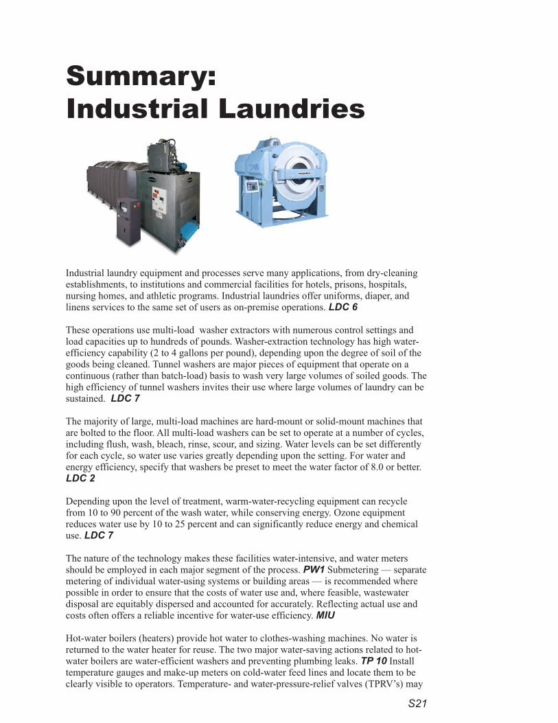
Industrial laundry equipment and processes serve many applications, from dry-cleaning establishments, to institutions and commercial facilities for hotels, prisons, hospitals, nursing homes, and athletic programs. Industrial laundries offer uniforms, diaper, and linens services to the same set of users as on-premise operations. LDC 6
These operations use multi-load washer extractors with numerous control settings and load capacities up to hundreds of pounds. Washer-extraction technology has high water-efficiency capability (2 to 4 gallons per pound), depending upon the degree of soil of the goods being cleaned. Tunnel washers are major pieces of equipment that operate on a continuous (rather than batch-load) basis to wash very large volumes of soiled goods. The high efficiency of tunnel washers invites their use where large volumes of laundry can be sustained. LDC 7
The majority of large, multi-load machines are hard-mount or solid-mount machines that are bolted to the floor. All multi-load washers can be set to operate at a number of cycles, including flush, wash, bleach, rinse, scour, and sizing. Water levels can be set differently for each cycle, so water use varies greatly depending upon the setting. For water and energy efficiency, specify that washers be preset to meet the water factor of 8.0 or better. LDC 2
Depending upon the level of treatment, warm-water-recycling equipment can recycle from 10 to 90 percent of the wash water, while conserving energy. Ozone equipment reduces water use by 10 to 25 percent and can significantly reduce energy and chemical use. LDC 7
The nature of the technology makes these facilities water-intensive, and water meters should be employed in each major segment of the process. PW1 Submetering — separate metering of individual water-using systems or building areas — is recommended where possible in order to ensure that the costs of water use and, where feasible, wastewater disposal are equitably dispersed and accounted for accurately. Reflecting actual use and costs often offers a reliable incentive for water-use efficiency. MIU
Hot-water boilers (heaters) provide hot water to clothes-washing machines. No water is returned to the water heater for reuse. The two major water-saving actions related to hot-water boilers are water-efficient washers and preventing plumbing leaks. TP 10 Install temperature gauges and make-up meters on cold-water feed lines and locate them to be clearly visible to operators. Temperature- and water-pressure-relief valves (TPRV’s) may
S22
open or leak. Make discharge pipes easy to inspect for flow, and ensure that there are visible indicators of whether a valve has activated. RP 3, 21
To save energy, water, and detergent and reduce air emissions, new facilities should seek possible areas of water recovery and reuse. PW 7
If water softeners are used, all softener systems should be equipped with controllers that activate based upon the volume of water treated. Alternatively, some controllers actually measure water hardness. Use water softeners and other treatments only when necessary, and don’t recharge softener systems based upon a timer. WT2-3 Where filtration systems are employed, require pressure gauges to determine when to backwash or change cartridges, and backwash based upon pressure differential. Install automatic-shutoff and solenoid valves on all hoses and water-using equipment. PW 7
Install faucets on set tubs and janitorial sinks with flows not to exceed 2.2 gpm. RP 3, 14-17
Employ these floor-cleaning efficiency practices: • Low-flow, high-pressure nozzles on hoses or water brooms used for floor and mat washing where a flow of
water is needed. RP 2, 19, FSP 18-20, PW 5, 7• Minimize the need to use a hose as a broom by installing drains close to areas where liquid discharges are
expected. PW 5, 7
Use high-efficiency toilets requiring not more than 1.3 gallons per flush and urinals which flush with 1 gallon or less. Use no automatically timed flushing systems. Use self-closing faucets with flows of 0.5 gpm for hand wash-ing. If available, and where codes and health departments permit, use non-potable water for flushing. RP 2, 5-9, 14-17
Conspicuously mark fire-protection plumbing so no connections will be made except for fire protection. Addition-ally, flow-detection meters should be installed on fire services to indicate unauthorized water flows. RP 4,23
Spaces where regular water use may result in spills or where floors may be washed frequently often have floor drains. Plumbing codes require traps to prevent gases and odors from seeping from sanitary sewers into rooms through the drains. The gas is blocked by water trapped below the drain in an “S” shaped pipe called a “P trap.” To sustain water in the trap in less frequently used spaces, additional water must be added with a device called a trap primer. A trap primer is a valve or other connection from a water source that allows a small amount of water to flow through pipes to recharge traps of one or more drains. Avoid continuous flow to trap primers. Instead, install pressure-activated or electronic trap primers, each serving several drains. RP3, 11-14
Photos:SmoothFlow® Batch Tunnel Washer System by Braun http://www.gabraun.com/equipment.aspx?id=22 G.A. Braun, Inc.
Large Open Pocket, End-Loading Washer/Extractors
S23
Summary:Dry Cleaners
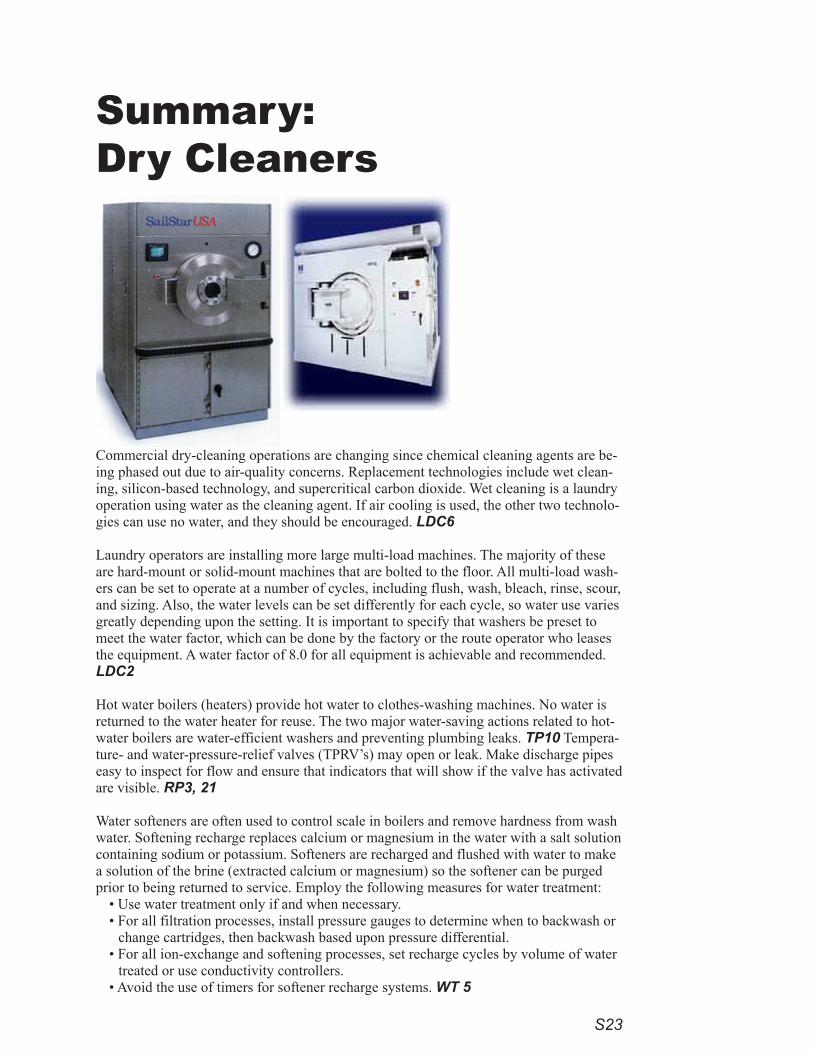
Commercial dry-cleaning operations are changing since chemical cleaning agents are be-ing phased out due to air-quality concerns. Replacement technologies include wet clean-ing, silicon-based technology, and supercritical carbon dioxide. Wet cleaning is a laundry operation using water as the cleaning agent. If air cooling is used, the other two technolo-gies can use no water, and they should be encouraged. LDC6
Laundry operators are installing more large multi-load machines. The majority of these are hard-mount or solid-mount machines that are bolted to the floor. All multi-load wash-ers can be set to operate at a number of cycles, including flush, wash, bleach, rinse, scour, and sizing. Also, the water levels can be set differently for each cycle, so water use varies greatly depending upon the setting. It is important to specify that washers be preset to meet the water factor, which can be done by the factory or the route operator who leases the equipment. A water factor of 8.0 for all equipment is achievable and recommended. LDC2
Hot water boilers (heaters) provide hot water to clothes-washing machines. No water is returned to the water heater for reuse. The two major water-saving actions related to hot-water boilers are water-efficient washers and preventing plumbing leaks. TP10 Tempera-ture- and water-pressure-relief valves (TPRV’s) may open or leak. Make discharge pipes easy to inspect for flow and ensure that indicators that will show if the valve has activated are visible. RP3, 21
Water softeners are often used to control scale in boilers and remove hardness from wash water. Softening recharge replaces calcium or magnesium in the water with a salt solution containing sodium or potassium. Softeners are recharged and flushed with water to make a solution of the brine (extracted calcium or magnesium) so the softener can be purged prior to being returned to service. Employ the following measures for water treatment:
• Use water treatment only if and when necessary. • For all filtration processes, install pressure gauges to determine when to backwash or
change cartridges, then backwash based upon pressure differential. • For all ion-exchange and softening processes, set recharge cycles by volume of water
treated or use conductivity controllers. • Avoid the use of timers for softener recharge systems. WT 5
S24
Floor cleaning may use wet methods, but wasteful open hoses are discouraged. Alternative methods include installing self-closing nozzles that limit flow to 5 gpm on washdown hoses. Low-flow, high-pressure nozzles on hoses and water brooms are preferred for floor and mat washing. RP 2,19 FSP 18-20
Conspicuously mark fire-protection plumbing so no connections will be made except for fire protection. Addition-ally, install flow-detection meters on fire services to indicate unauthorized water flows. RP 4,23
Spaces where regular water use may result in spills or where floors may be washed frequently often have floor drains. Plumbing codes require traps to prevent gases and odors from seeping from sanitary sewers into rooms through the drains. The gas is blocked by water trapped below the drain in an “S” shaped pipe called a “P trap.” To sustain water in the trap in less frequently used spaces, additional water must be added with a device called a trap primer. A trap primer is a valve or other connection from a water source that allows a small amount of water to flow through pipes to recharge traps of one or more drains. Avoid continuous flow to trap primers. Instead, install pressure-activated or electronic trap primers, each serving several drains. RP3, 11-14
Install automatic-shutoff and solenoid valves on all hoses and water-using equipment. PW 7
Install faucets on set tubs and janitorial sinks with flows not to exceed 2.2 gpm. RP 3, 14-17 Employ these floor-cleaning efficiency practices:
• Low-flow, high-pressure nozzles on hoses or water brooms used for floor and mat washing where a flow of water is needed. RP 2, 19, FSP 18-20, PW 5, 7
• Minimize the need to use a hose as a broom by installing drains close to areas where liquid discharges are expected. PW 5, 7
Use high-efficiency toilets requiring not more than 1.3 gallons per flush and urinals which flush with 1 gallon or less. Use no automatically timed flushing systems. Use self-closing faucets with flows of 0.5 gpm for hand wash-ing. If available, and where codes and health departments permit, use non-potable water for flushing. RP 2, 5-9, 14-17

S2�
Summary:Vehicle Washes
Water efficiency can be achieved in commercial vehicle washes (conveyor, in-bay auto-matic, and self-service) through a combination of both proper equipment and operational measures. New-vehicle dealers, fleet-vehicle operators, and rental agencies should also use these water-efficiency measures. In all new vehicle-wash businesses, except for self-service, reclaim systems can save 50 percent or more of potable water use. In vehicle washes on industrial sites with limited public access, wash systems can be designed to capture rainfall and use aerobic treatment systems, reducing the use of potable water for washing to less than 10 percent.
The important water efficiency measures pertinent to vehicle washing are: • Proper choice of cleaning equipment, settings, and orientation. • Spray nozzles on arches which produce a fan-shaped spray, oriented parallel to the
spray bar. VW 2-3 • Friction components for wash cycles in every vehicle wash. These components, such
as mitters or brushes, are more efficient than “touchless” washes, which use higher pressure and, therefore, usually discharge more water. VW 1
Recycling wash water can replace 50 percent or more of the freshwater use:• Gun-type and undercarriage nozzles should be used only with reclaimed water. VW
2-3• Provide reclaimed water to the pre-soak, undercarriage, and initial wash cycles, at a
minimum. VW 2-3 • Preferred reclaim systems will have sufficient filtration capacity to provide reuse
water for all cycles except the final rinse. VW 3•Where reverse osmosis is used, the reject water should be reused in the washing pro-
cess or applied to landscape irrigation. VW 3-4
Water softeners are often used to remove water hardness for washing. Softening recharge replaces calcium or magnesium in the water with a salt solution containing sodium or potassium. Softeners are recharged and flushed with water to make the brine solutions and to purge the softener of brine prior to being returned to service. All softener systems should be equipped with controllers that activate based upon the volume of water treated. Alternatively, use controllers that actually measure the hardness. Prohibit timers for soft-ener recharge systems. Where filtration systems are employed, require pressure gauges to determine when to backwash or change cartridges, and backwash based upon pressure differential. Evaluate opportunities to reuse backwash waste streams. Use water softeners and other treatment only when necessary. WT2-3

S26
Based upon the pump’s designed optimum operating pressure, nozzle flow-rate for self-service vehicle washes should be no more than 3 gallons per minute. WM 4
Washes including a spot-free rinse option should use deionization equipment, rather than water-softening or re-verse-osmosis systems. VW 3
For on-site towel washing, high-efficiency machines with a CEE rating of Tier 3, indicating a water factor of 4.5 gallons per cubic foot of washer capacity, should be used. VW 2, LDC 1
Other water-efficiency measures apply to customer convenience and structure plumbing.
Install automatic-shutoff and solenoid valves on all hoses and water-using equipment. PW 7
Install faucets on set tubs and janitorial sinks with flows not to exceed 2.2 gpm. RP 3, 14-17 Employ these floor-cleaning efficiency practices:
• Low-flow, high-pressure nozzles on hoses or water brooms used for floor and mat washing where a flow of water is needed. RP 2, 19, FSP 18-20, PW 5, 7
• Minimize the need to use a hose as a broom by installing drains close to areas where liquid discharges are expected. PW 5, 7
Use high-efficiency toilets requiring not more than 1.3 gallons per flush and urinals which flush with 1 gallon or less. Use no automatically timed flushing systems. Use self-closing faucets with flows of 0.5 gpm for hand wash-ing. If available, and where codes and health departments permit, use non-potable water for flushing. RP 2, 5-9, 14-17
Conspicuously mark fire-protection plumbing so no connections will be made except for fire protection. Addition-ally, install flow-detection meters on fire services to indicate unauthorized water flows. RP 4,23
Where irrigated landscaping or water features are present, refer to “Water Features, Pools, and Landscapes.
S27
Summary: Beverage Manufacturers
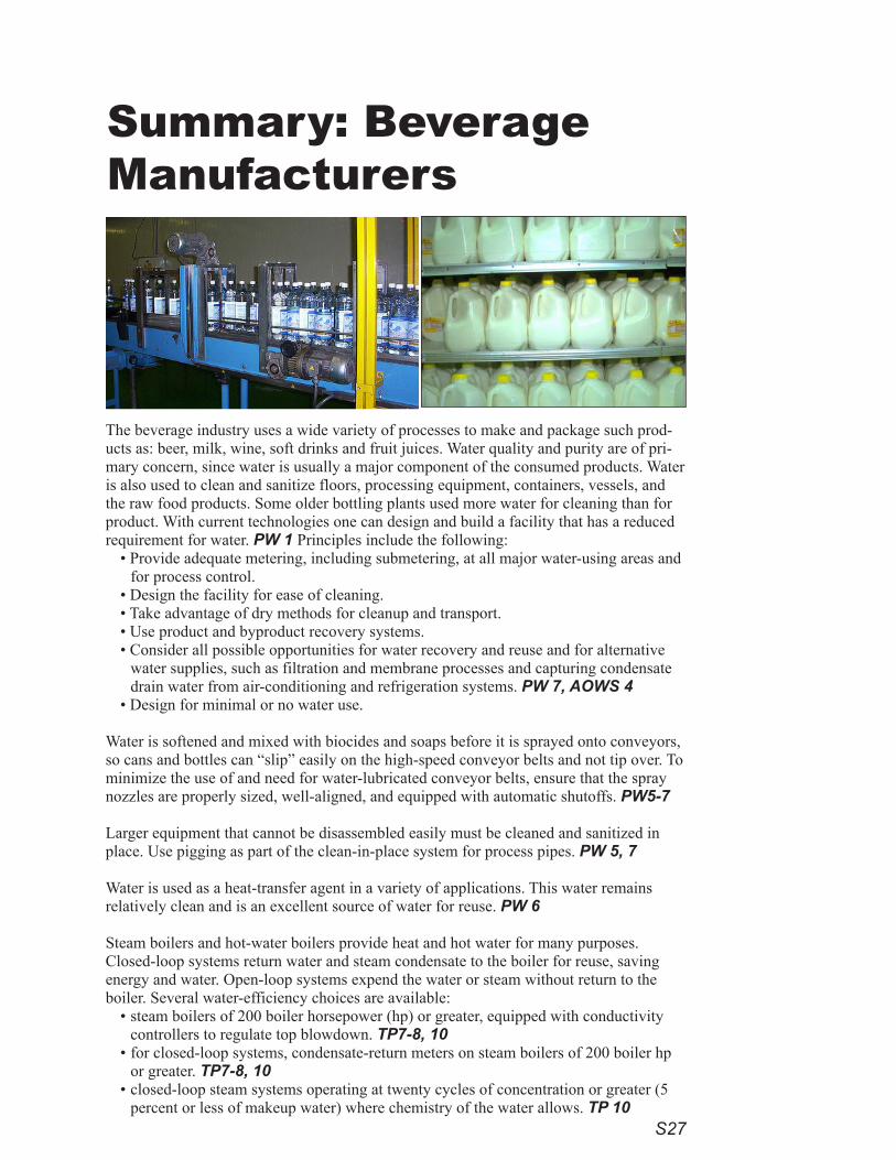
The beverage industry uses a wide variety of processes to make and package such prod-ucts as: beer, milk, wine, soft drinks and fruit juices. Water quality and purity are of pri-mary concern, since water is usually a major component of the consumed products. Water is also used to clean and sanitize floors, processing equipment, containers, vessels, and the raw food products. Some older bottling plants used more water for cleaning than for product. With current technologies one can design and build a facility that has a reduced requirement for water. PW 1 Principles include the following:
• Provide adequate metering, including submetering, at all major water-using areas and for process control.
• Design the facility for ease of cleaning.• Take advantage of dry methods for cleanup and transport. • Use product and byproduct recovery systems. • Consider all possible opportunities for water recovery and reuse and for alternative
water supplies, such as filtration and membrane processes and capturing condensate drain water from air-conditioning and refrigeration systems. PW 7, AOWS 4
• Design for minimal or no water use.
Water is softened and mixed with biocides and soaps before it is sprayed onto conveyors, so cans and bottles can “slip” easily on the high-speed conveyor belts and not tip over. To minimize the use of and need for water-lubricated conveyor belts, ensure that the spray nozzles are properly sized, well-aligned, and equipped with automatic shutoffs. PW5-7
Larger equipment that cannot be disassembled easily must be cleaned and sanitized in place. Use pigging as part of the clean-in-place system for process pipes. PW 5, 7
Water is used as a heat-transfer agent in a variety of applications. This water remains relatively clean and is an excellent source of water for reuse. PW 6
Steam boilers and hot-water boilers provide heat and hot water for many purposes. Closed-loop systems return water and steam condensate to the boiler for reuse, saving energy and water. Open-loop systems expend the water or steam without return to the boiler. Several water-efficiency choices are available:
•steam boilers of 200 boiler horsepower (hp) or greater, equipped with conductivity controllers to regulate top blowdown. TP7-8, 10
•for closed-loop systems, condensate-return meters on steam boilers of 200 boiler hp or greater. TP7-8, 10
•closed-loop steam systems operating at twenty cycles of concentration or greater (5 percent or less of makeup water) where chemistry of the water allows. TP 10

S28
•steam-distribution lines and equipment with steam traps meeting all codes.•make-up meters on feed-water lines:
to steam boilers and water boilers of more than 100,000 Btus per hour. TP 8-10to closed-loop hot-water systems for heating. TP 9-10
• boiler-temperature and make-up meters that are clearly visible to operators. TP 11•discharge pipes that are easy to inspect for flow and visible indicators that will indicate whether the valve has
activated, thereby reducing plumbing leaks due to repeated openings of water-temperature- and pressure-relief valves (TPRVs). RP3, 21
Cooling towers remove heat generated in a manufacturing process or by air-conditioning or refrigeration equip-ment. Energy-efficient equipment may reduce such waste heat, otherwise removed by a central refrigeration system and a compressorthat is air-cooled or connected with a circulating loop to a cooling tower or evaporative condenser. As warm water from the compressor trickles through the cooling tower, some evaporates, cooling the remaining water, which returns to cool the equipment. Measures to reduce water waste in cooling towers include:
• performing a life-cycle analysis, including all operating, capital, and personnel costs, to determine whether use of a cooling tower is more cost-effective than air cooling.
• equipping towers with conductivity controllers, make-up and blowdown meters, and overflow alarms. TP 4-6 • operating towers at a minimum of five cycles of concentration in the San Francisco and East Bay Municipal
Utility District areas for towers using potable water, depending upon the chemistry of the make-up water used, including considerations for reclaimed water or on-site sources. TP 4-6
• avoiding once-through cooling with potable water. FSO 2-3• using high-efficiency drift eliminators that reduce drift loss to less than 0.002 percent of circulating water
volume for cross-flow towers and 0.001 percent for counter-flow towers. TP 4-6 • evaluating the processes in the plant for maximum energy efficiency and waste-heat recovery, since a more
efficient building will reject less heat to the cooling tower. TP7• providing adequate training to cooling-tower operators. TP 7
Water treatment is important in beverage manufacturing to provide the right taste, color, pH, and other quality characteristics to the finished product. Measures to improve the efficiency of water treatment include:
•for all filtration processes, installing pressure gauges to determine when to backwash or change cartridges, followed by backwash based upon pressure differential.
•for all ion-exchange and softening processes, setting recharge cycles by volume of water treated or using con-ductivity controllers.
•avoiding the use of timers for softener-recharge systems. •using water treatment only when necessary. • use a reverse osmosis and nanofiltration systems with the lowest reject rate for its size. • choose distillation equipment that recovers at least 85 percent of the feed water. WT 5
Install automatic-shutoff and solenoid valves on all hoses and water-using equipment. PW 7
Install faucets on set tubs and janitorial sinks with flows not to exceed 2.2 gpm. RP3, 14-17 Employ these floor-cleaning efficiency practices:
• Low-flow, high-pressure nozzles on hoses or water brooms used for floor and mat washing where a flow of water is needed. RP 2, 19, FSP 18-20, PW 5, 7
• Minimize the need to use a hose as a broom by installing drains close to areas where liquid discharges are expected. PW 5, 7
Use high-efficiency toilets requiring no more than 1.3 gallons per flush and urinals which flush with 1 gallon or less. Avoid automatically timed flushing systems. Use self-closing faucets with flows of 0.5 gpm for hand wash-ing. If available, and if codes and health departments permit, flush with non-potable water. RP 2, 5-9, 14-17
Conspicuously mark fire-protection plumbing so no connections will be made except for fire protection. Addition-ally, install flow-detection meters on fire services to indicate unauthorized water flows. RP 4,23
Photo: http://creativecommons.org/licenses/by-nc-nd/2.0/deed.en at http://www.flickr.com/photos/anchorage/33564092/
»»
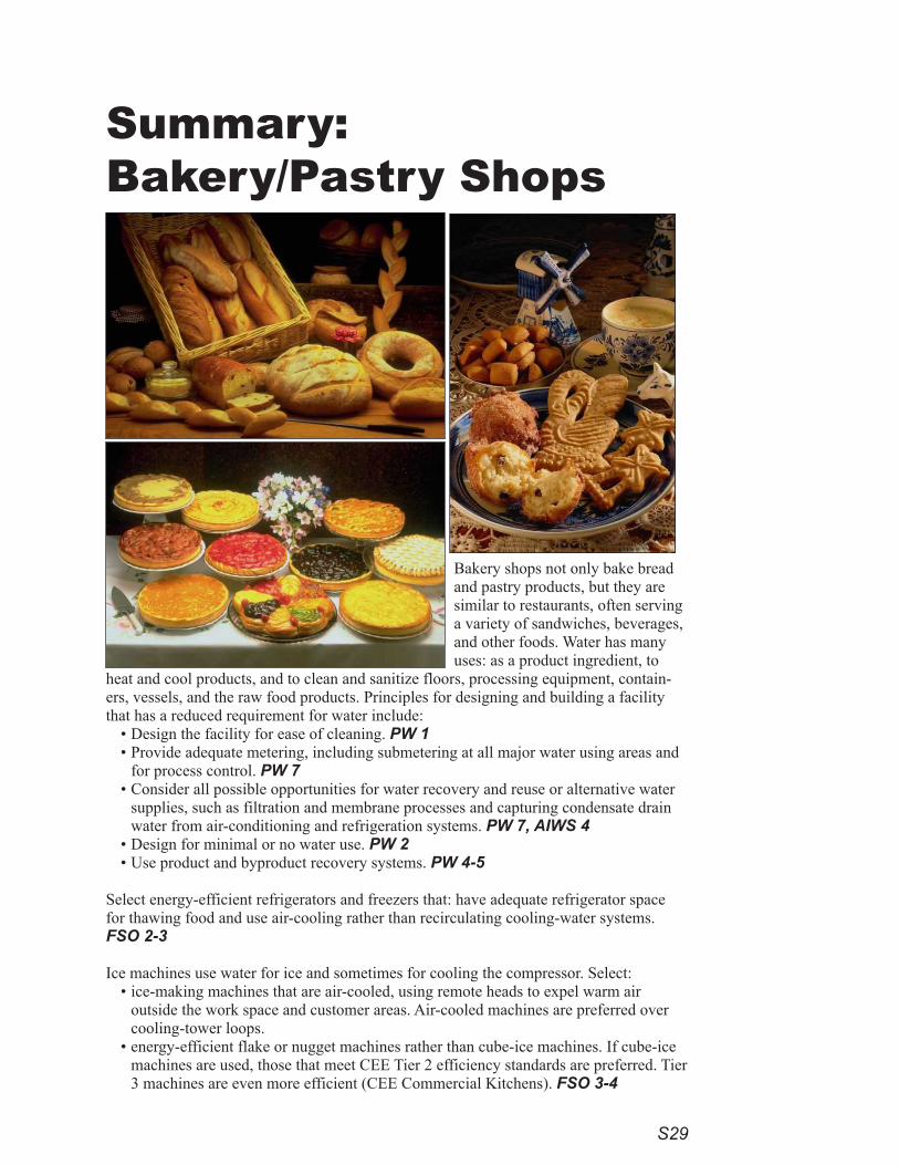
S29
Summary: Bakery/Pastry Shops
Bakery shops not only bake bread and pastry products, but they are similar to restaurants, often serving a variety of sandwiches, beverages, and other foods. Water has many uses: as a product ingredient, to
heat and cool products, and to clean and sanitize floors, processing equipment, contain-ers, vessels, and the raw food products. Principles for designing and building a facility that has a reduced requirement for water include:
• Design the facility for ease of cleaning. PW 1• Provide adequate metering, including submetering at all major water using areas and
for process control. PW 7• Consider all possible opportunities for water recovery and reuse or alternative water
supplies, such as filtration and membrane processes and capturing condensate drain water from air-conditioning and refrigeration systems. PW 7, AIWS 4
• Design for minimal or no water use. PW 2• Use product and byproduct recovery systems. PW 4-5
Select energy-efficient refrigerators and freezers that: have adequate refrigerator space for thawing food and use air-cooling rather than recirculating cooling-water systems. FSO 2-3
Ice machines use water for ice and sometimes for cooling the compressor. Select: • ice-making machines that are air-cooled, using remote heads to expel warm air
outside the work space and customer areas. Air-cooled machines are preferred over cooling-tower loops.
• energy-efficient flake or nugget machines rather than cube-ice machines. If cube-ice machines are used, those that meet CEE Tier 2 efficiency standards are preferred. Tier 3 machines are even more efficient (CEE Commercial Kitchens). FSO 3-4
S30
If combination ovens are used, select those that use no more than 15 gallons per hour and comply with the Cali-fornia energy rebate list prepared by Fisher-Nickel. FSO 7-8
If steamers are used, select those that are either connectionless or boilerless and consume no more than three gal-lons of water per hour. FSO 7
Dishwashing is a water-intensive process for cleaning and sanitizing. • Use pre-rinse spray valves (1.5 gpm maximum) for dish rinsing. FSO 10-11 • Install strainer (scrapper) baskets instead of garbage disposals (grinder). If a water-using grinder is selected,
install a water-saver kit or choose a grinder that tailors the water use to the load. FSO 9-10 • Avoid “dump and fill” dishwashing machines; use dishwashers meeting Energy Star efficiency standards.
FSO 11-13 • Install steam doors to reduce evaporation.
Water is used as a heat-transfer agent in a variety of applications. This water remains relatively clean and is an excellent source of water for reuse. PW 6
Steam boilers and hot-water boilers provide heat and hot water. Closed-loop systems return water and steam condensate to the boiler for reuse, saving both energy and water. Open-loop systems expend the water or steam without return to the boiler. Several water efficiency measures are available:
• reduce plumbing leaks due to repeated opening of water temperature- and pressure-relief valves (TPRV’s). • make discharge pipes easy to inspect for flow, and insert visible indicators of valve activation. RP 3, 21
Measures to improve the efficiency of water treatment include:• For all filtration processes, install pressure gauges to determine when to backwash or change cartridges, then
backwash based upon pressure differential. • For all ion-exchange and softening processes, set recharge cycles by volume of water treated or use conductiv-
ity controllers. • Avoid the use of timers for softener-recharge systems. • Use water treatment only if and when necessary. WT 5
Install automatic-shutoff and solenoid valves on all hoses and water-using equipment. PW 7
Install faucets on set tubs and janitorial sinks with flows not to exceed 2.2 gpm. RP 3, 14-17
Employ these floor-cleaning efficiency practices: • Low-flow, high-pressure nozzles on hoses or water brooms used for floor and mat washing where a flow of
water is needed. RP 2, 19, FSP 18-20, PW 5, 7• Minimize the need to use a hose as a broom by installing drains close to areas where liquid discharges are
expected. PW 5, 7
Use high-efficiency toilets requiring not more than 1.3 gallons per flush and urinals which flush with 1 gallon or less. Use no automatically timed flushing systems. Use self-closing faucets with flows of 0.5 gpm for hand wash-ing. If available, and where codes and health departments permit, use non-potable water for flushing. RP 2, 5-9, 14-17
Conspicuously mark fire-protection plumbing so no connections will be made except for fire protection. Addition-ally, install flow-detection meters on fire services to indicate unauthorized water flows. RP 4,23
S31
Summary:Industrial Bakeries
Water quality is of primary concern in industrial bakery processes since bak-ery products are made for human con-
sumption. Water is used to heat and cool products, to transport raw product, and to clean and sanitize: floors, processing equipment, containers, vessels, and raw food products.
With modern technologies, it is possible to design and build a facility that has a reduced requirement for water. PW 1
• Provide adequate metering, submetering at all major water using areas, and for pro-cess control. PW 7
• Use product and byproduct recovery systems. PW 4-5• Consider all possible opportunities for water recovery and reuse, or alternative water
supplies, such as filtration and membrane processes, capturing condensate drain water from air conditioning and refrigeration systems. PW 7, AOWS 4
• Design for minimal or no water use. PW 2 • Design the facility for ease of cleaning. PW 1• Take advantage of dry methods for cleanup and transport. PW 3
If applicable, minimize the use of water on water-lubricated conveyor belts by ensuring that spray nozzles are properly sized, well-aligned, and equipped with automatic shutoffs. PW5-7
Larger equipment that cannot be disassembled easily must be cleaned in place and sani-tized in place. Use pigging in the clean-in-place system for process pipes. PW 5, 7
Water is used for a variety of applications as a heat-transfer agent. This water remains relatively clean and is an excellent source of water for reuse. PW 6
Steam boilers and hot-water boilers provide heat and hot water for many purposes. Closed-loop systems return water and steam condensate to the boiler for reuse, saving energy and water. Open-loop systems expend the water or steam without return to the boiler. Several water-efficiency choices are available:
•steam boilers of 200 boiler horsepower (hp) or greater, equipped with conductivity controllers to regulate top blowdown. TP7-8, 10
•for closed-loop systems, condensate-return meters on steam boilers of 200 boiler hp or greater. TP7-8, 10
•closed-loop steam systems operating at twenty cycles of concentration or greater (5 percent or less of makeup water) where chemistry of the water allows. TP 10
•steam-distribution lines and equipment with steam traps meeting all codes.
S32
•make-up meters on feed-water lines:to steam boilers and water boilers of more than 100,000 Btus per hour. TP 8-10to closed-loop hot-water systems for heating. TP 9-10
• boiler-temperature and make-up meters that are clearly visible to operators. TP 11•discharge pipes that are easy to inspect for flow and visible indicators that will indicate whether the valve has
activated, thereby reducing plumbing leaks due to repeated openings of water-temperature- and pressure-relief valves (TPRVs). RP3, 21
Cooling towers remove heat generated in a manufacturing process or by air-conditioning or refrigeration equip-ment. Energy-efficient equipment may reduce such waste heat, which is usually removed by a central refrigeration system and compressor. The compressor may be air-cooled or connected with a circulating loop to a cooling tower or evaporative condenser. As warm water from the compressor trickles through the cooling tower, some water evaporates, cooling the remaining water, which returns to cool the equipment. Measures to reduce water waste in cooling towers include:
• performing a life-cycle analysis, including all operating, capital, and personnel costs, to determine whether use of a cooling tower is more cost-effective than air cooling.
• equipping cooling towers with conductivity controllers, make-up and blowdown meters, and overflow alarms. TP 4-6
• operating towers at a minimum of five cycles of concentration in the San Francisco and East Bay Municipal Utility District areas for towers using potable water, depending upon the chemistry of the make-up water used, including considerations for reclaimed water or on-site sources. TP 4-6
• avoiding once-through cooling with potable water. FSO 2-3• using high-efficiency drift eliminators that reduce drift loss to less than 0.002 percent of circulating water
volume for cross-flow towers and 0.001 percent for counter-flow towers. TP 4-6 • evaluating the processes in the plant for maximum energy efficiency and waste-heat recovery, since a more
efficient building will reject less heat to the cooling tower. TP7• providing adequate training to cooling-tower operators. TP 7
Measures to improve the efficiency of water treatment include:•for all filtration processes, installing pressure gauges to determine when to backwash or change cartridges,
followed by backwash based upon pressure differential. •for all ion-exchange and softening processes, setting recharge cycles by volume of water treated or using con-
ductivity controllers. •avoiding the use of timers for softener-recharge systems. •using water treatment only when necessary. • use a reverse osmosis and nanofiltration systems with the lowest reject rate for its size. • choose distillation equipment that recovers at least 85 percent of the feed water. WT 5
Install automatic-shutoff and solenoid valves on all hoses and water-using equipment. PW 7
Install faucets on set tubs and janitorial sinks with flows not to exceed 2.2 gpm. RP3, 14-17 Employ these floor-cleaning efficiency practices:
• Low-flow, high-pressure nozzles on hoses or water brooms used for floor and mat washing where a flow of water is needed. RP 2, 19, FSP 18-20, PW 5, 7
• Minimize the need to use a hose as a broom by installing drains close to areas where liquid discharges are expected. PW 5, 7
Use high-efficiency toilets requiring no more than 1.3 gallons per flush and urinals which flush with 1 gallon or less. Avoid automatically timed flushing systems. Use self-closing faucets with flows of 0.5 gpm for hand wash-ing. If available, and if codes and health departments permit, flush with non-potable water. RP 2, 5-9, 14-17
Conspicuously mark fire-protection plumbing so no connections will be made except for fire protection. Addition-ally, install flow-detection meters on fire services to indicate unauthorized water flows. RP 4,23
Photo:http://www.freefoto.com/browse/09-05-0?ffid=09-05-0
»»
S33
Automotive service and repair is one of the most common types of commercial enter-prises in any city. Establishments include: service stations, oil change/lubrication, body repair, tune-up shops, full-service repair shops, fleet maintenance, and tire services. The design of a water-efficient shop depends to some extent upon the type of service offered. New air-quality regulations have also meant that shops have switched from solvent-based parts and brake-cleaning systems to aqueous-based systems. Water-efficiency measures for vehicle cleaning are described in the summary sheet for “Vehicle Washes.”
Floor-cleaning with dry methods, preventing spills and leaks from entering the wastewa-ter discharge system, and proper design of oil separators have as much to do with pollu-tion prevention as they do with water conservation. PW 9-10 To achieve this:
• Install recirculating filtration equipment to minimize the need to dump water from aqueous parts- and brake-cleaning equipment.
• Seal shop floors to ensure easy cleanup. • Properly identify all drains.• If hoses are used, install automatic-shutoff and solenoid valves on all hoses and water-
using equipment, where applicable.
Operational measures to be recommended at the time of permitting to reduce water use for cleanup include the following:
• Use mopping or dry cleaning where possible.• Use pressure-washing equipment instead of hoses.• Place drip pans under vehicles.• Provide proper facilities for the capture, storage, and recycling of spent fluids, oils,
and fuels, including antifreeze and radiator flush water. • Provide secondary containers to catch drips, leaks, and spills from stored liquids and
solvents.
Measures to improve the efficiency of water treatment include:•for all filtration processes, installing pressure gauges to determine when to backwash
or change cartridges, followed by backwash based upon pressure differential. •for all ion-exchange and softening processes, setting recharge cycles by volume of
water treated or using conductivity controllers. •avoiding the use of timers for softener-recharge systems. •using water treatment only when necessary. WT 5
Summary: Auto Service and Repair Shops

S34
Use high-efficiency toilets requiring no more than 1.3 gallons per flush and urinals which flush with 1 gallon or less. Avoid automatically timed flushing systems. Use self-closing faucets with flows of 0.5 gpm for hand wash-ing. If available, and if codes and health departments permit, flush with non-potable water. RP 2, 5-9, 14-17
Conspicuously mark fire-protection plumbing so no connections will be made except for fire protection. Addition-ally, install flow-detection meters on fire services to indicate unauthorized water flows. RP 4,23
Install automatic-shutoff and solenoid valves on all hoses and water-using equipment. PW 7
Install faucets on set tubs and janitorial sinks with flows not to exceed 2.2 gpm. RP3, 14-17
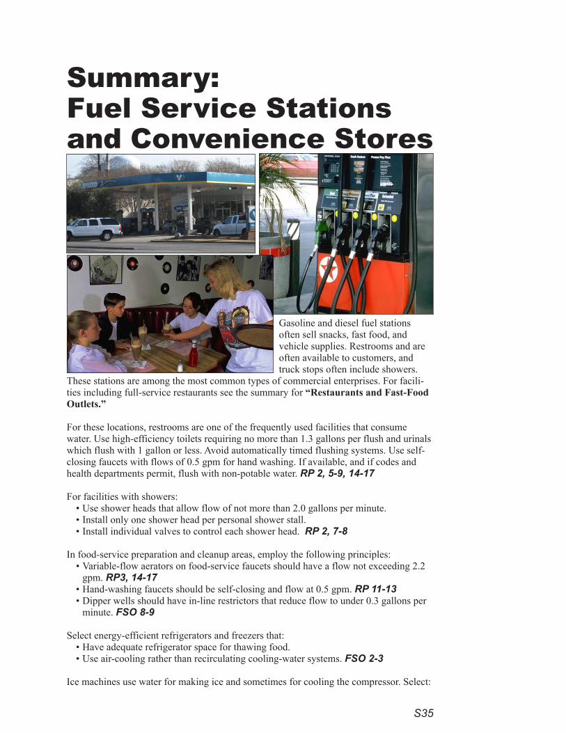
S3�
Summary: Fuel Service Stations and Convenience Stores
Gasoline and diesel fuel stations often sell snacks, fast food, and vehicle supplies. Restrooms and are often available to customers, and truck stops often include showers.
These stations are among the most common types of commercial enterprises. For facili-ties including full-service restaurants see the summary for “Restaurants and Fast-Food Outlets.”
For these locations, restrooms are one of the frequently used facilities that consume water. Use high-efficiency toilets requiring no more than 1.3 gallons per flush and urinals which flush with 1 gallon or less. Avoid automatically timed flushing systems. Use self-closing faucets with flows of 0.5 gpm for hand washing. If available, and if codes and health departments permit, flush with non-potable water. RP 2, 5-9, 14-17
For facilities with showers:• Use shower heads that allow flow of not more than 2.0 gallons per minute. • Install only one shower head per personal shower stall. • Install individual valves to control each shower head. RP 2, 7-8
In food-service preparation and cleanup areas, employ the following principles:• Variable-flow aerators on food-service faucets should have a flow not exceeding 2.2
gpm. RP3, 14-17• Hand-washing faucets should be self-closing and flow at 0.5 gpm. RP 11-13• Dipper wells should have in-line restrictors that reduce flow to under 0.3 gallons per
minute. FSO 8-9
Select energy-efficient refrigerators and freezers that:• Have adequate refrigerator space for thawing food. • Use air-cooling rather than recirculating cooling-water systems. FSO 2-3
Ice machines use water for making ice and sometimes for cooling the compressor. Select:
S36
• ice-making machines that are air-cooled, using remote heads to expel warm air outside the work space and customer areas. Air-cooled machines are preferred over cooling-tower loops.
• energy-efficient flake or nugget machines rather than cube-ice machines. If cube-ice machines are used, those that meet CEE Tier 2 efficiency standards are preferred. Tier 3 machines are even more efficient (CEE Com-mercial Kitchens). FSO 3-4
Dishwashing is a water intensive process for cleaning and sanitizing. • Use pre-rinse spray valves (1.5 gpm maximum) for dish rinsing. FSO 10-11 • Strainer (scrapper) baskets are preferred to garbage disposals (grinders). If a water-using grinder is selected,
install a water-saver kit or choose a grinder that tailors the water use to the load. FSO 9-10 • Avoid “dump and fill” dishwashing machines. Use dishwashers meeting Energy Star efficiency standards.
Install automatic-shutoff and solenoid valves on all hoses and water-using equipment. PW 7
Install faucets on set tubs and janitorial sinks with flows not to exceed 2.2 gpm. RP 3, 14-17 Employ these floor-cleaning efficiency practices:
• Low-flow, high-pressure nozzles on hoses or water brooms used for floor and mat washing where a flow of water is needed. RP 2, 19, FSP 18-20, PW 5, 7
• Minimize the need to use a hose as a broom by installing drains close to areas where liquid discharges are expected. PW 5, 7
Spaces where regular water use may result in spills or where floors may be washed frequently often have floor drains. Plumbing codes require traps to prevent gases and odors from seeping from sanitary sewers into rooms through the drains. The gas is blocked by water trapped below the drain in an “S” shaped pipe called a “P trap.” To sustain water in the trap in less frequently used spaces, additional water must be added with a device called a trap primer. A trap primer is a valve or other connection from a water source that allows a small amount of water to flow through pipes to recharge traps of one or more drains. Avoid continuous flow to trap primers. Instead, install pressure-activated or electronic trap primers, each serving several drains. RP3, 11-14
Conspicuously mark fire protection plumbing so no connections will be made except for fire protection. Addition-ally, install flow-detection meters on fire services to indicate unauthorized water flows. RP4,23
Make discharge pipes easy to inspect for flow and insert visible indicators that will show if the water pressure relief or temperature relief valves have activated. RP3, 21
Measures to improve the efficiency of water treatment include:•for all filtration processes, installing pressure gauges to determine when to backwash or change cartridges,
followed by backwash based upon pressure differential. •for all ion-exchange and softening processes, setting recharge cycles by volume of water treated or using con-
ductivity controllers. •avoiding the use of timers for softener-recharge systems. •using water treatment only when necessary. • use a reverse osmosis and nanofiltration systems with the lowest reject rate for its size. • choose distillation equipment that recovers at least 85 percent of the feed water. WT 5
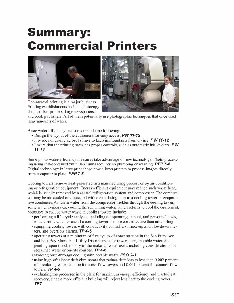
S37
Summary:Commercial Printers
Commercial printing is a major business. Printing establishments include photocopy shops, offset printers, large newspapers, and book publishers. All of them potentially use photographic techniques that once used large amounts of water.
Basic water-efficiency measures include the following:• Design the layout of the equipment for easy access. PW 11-12• Provide nondrying aerosol sprays to keep ink fountains from drying. PW 11-12• Ensure that the printing press has proper controls, such as automatic ink levelers. PW
11-12
Some photo water-efficiency measures take advantage of new technology. Photo process-ing using self-contained “mini lab” units requires no plumbing or washing. PFP 7-8 Digital technology in large print shops now allows printers to process images directly from computer to plate. PFP 7-8
Cooling towers remove heat generated in a manufacturing process or by air-condition-ing or refrigeration equipment. Energy-efficient equipment may reduce such waste heat, which is usually removed by a central refrigeration system and compressor. The compres-sor may be air-cooled or connected with a circulating loop to a cooling tower or evapora-tive condenser. As warm water from the compressor trickles through the cooling tower, some water evaporates, cooling the remaining water, which returns to cool the equipment. Measures to reduce water waste in cooling towers include:
• performing a life-cycle analysis, including all operating, capital, and personnel costs, to determine whether use of a cooling tower is more cost-effective than air cooling.
• equipping cooling towers with conductivity controllers, make-up and blowdown me-ters, and overflow alarms. TP 4-6
• operating towers at a minimum of five cycles of concentration in the San Francisco and East Bay Municipal Utility District areas for towers using potable water, de-pending upon the chemistry of the make-up water used, including considerations for reclaimed water or on-site sources. TP 4-6
• avoiding once-through cooling with potable water. FSO 2-3• using high-efficiency drift eliminators that reduce drift loss to less than 0.002 percent
of circulating water volume for cross-flow towers and 0.001 percent for counter-flow towers. TP 4-6
• evaluating the processes in the plant for maximum energy efficiency and waste-heat recovery, since a more efficient building will reject less heat to the cooling tower. TP7
S38
• providing adequate training to cooling-tower operators. TP 7
Consider all possible opportunities for water recovery and reuse or alternative water supplies, such as filtration and membrane processes and capturing condensate drain water from air-conditioning systems. PW 7, AOWS 4
Additional water-efficiency measures include the following:• Operate closed-loop steam systems at twenty cycles of concentration or greater (5 percent or less of make-up
water) where water chemistry allows. TP 10• Equip steam distribution lines and equipment with steam traps meeting all codes.• Install make-up meters on feed-water lines to:
steam boilers and water boilers of more than 100,000 Btus per hour. TP 8-10closed-loop hot-water systems for heating. TP 9-10
• Situate boiler temperature and make-up meters to be clearly visible to operators. TP 11• Reduce plumbing leaks due to repeated opening of water-temperature and pressure-relief valves (TPRV’s).• Make discharge pipes easy to inspect for flow and there should be visible indicators of any valve activation.
RP 3, 21
In some cases water treatment may be used to ensure an attractive quality for the finished images. Measures to improve water efficiency in water treatment include:
•for all filtration processes, installing pressure gauges to determine when to backwash or change cartridges, followed by backwash based upon pressure differential.
•for all ion-exchange and softening processes, setting recharge cycles by volume of water treated or using con-ductivity controllers.
•avoiding the use of timers for softener-recharge systems. •using water treatment only when necessary. • use a reverse osmosis and nanofiltration systems with the lowest reject rate for its size. • choose distillation equipment that recovers at least 85 percent of the feed water. WT 5
Install automatic-shutoff and solenoid valves on all hoses and water-using equipment. PW 7
Install faucets on set tubs and janitorial sinks with flows not to exceed 2.2 gpm. RP3, 14-17 Employ these floor-cleaning efficiency practices:
• Low-flow, high-pressure nozzles on hoses or water brooms used for floor and mat washing where a flow of water is needed. RP 2, 19, FSP 18-20, PW 5, 7
• Minimize the need to use a hose as a broom by installing drains close to areas where liquid discharges are expected. PW 5, 7
Use high-efficiency toilets requiring no more than 1.3 gallons per flush and urinals which flush with 1 gallon or less. Avoid automatically timed flushing systems. Use self-closing faucets with flows of 0.5 gpm for hand wash-ing. If available, and if codes and health departments permit, flush with non-potable water. RP 2, 5-9, 14-17
Conspicuously mark fire-protection plumbing so no connections will be made except for fire protection. Addition-ally, install flow-detection meters on fire services to indicate unauthorized water flows. RP 4,23
Photos:Catherine Putsche
»»
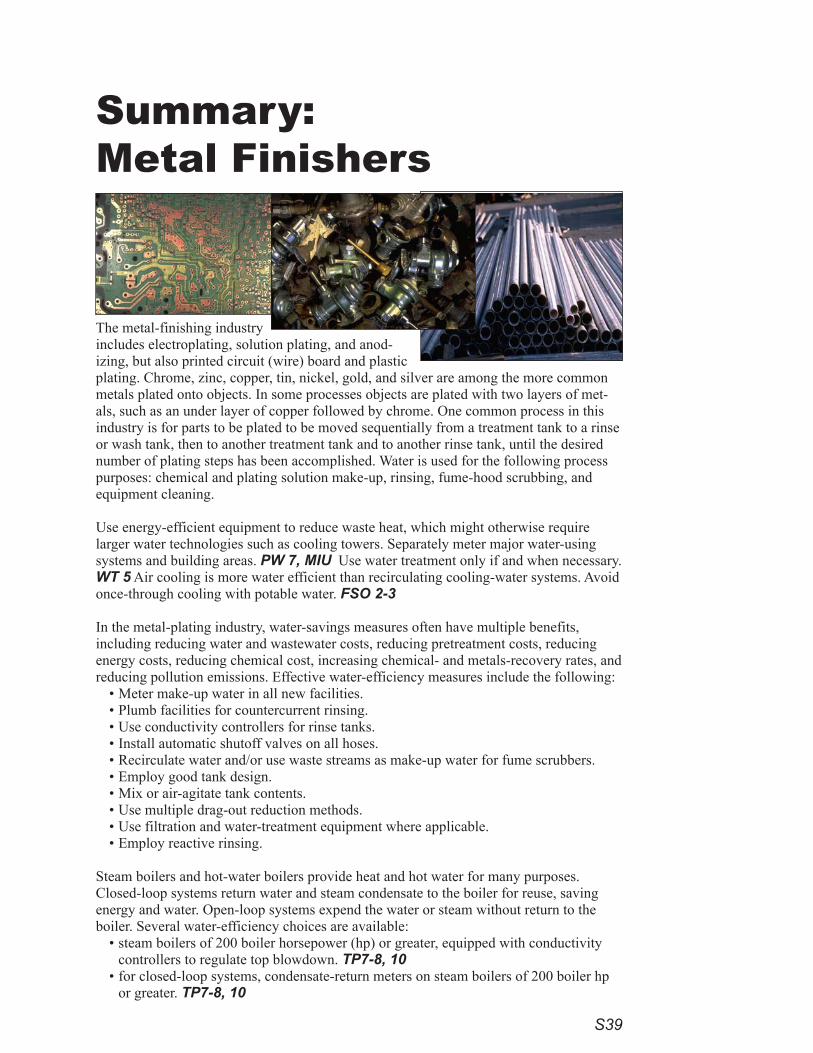
S39
Summary: Metal Finishers
The metal-finishing industry includes electroplating, solution plating, and anod-izing, but also printed circuit (wire) board and plastic plating. Chrome, zinc, copper, tin, nickel, gold, and silver are among the more common metals plated onto objects. In some processes objects are plated with two layers of met-als, such as an under layer of copper followed by chrome. One common process in this industry is for parts to be plated to be moved sequentially from a treatment tank to a rinse or wash tank, then to another treatment tank and to another rinse tank, until the desired number of plating steps has been accomplished. Water is used for the following process purposes: chemical and plating solution make-up, rinsing, fume-hood scrubbing, and equipment cleaning.
Use energy-efficient equipment to reduce waste heat, which might otherwise require larger water technologies such as cooling towers. Separately meter major water-using systems and building areas. PW 7, MIU Use water treatment only if and when necessary. WT 5 Air cooling is more water efficient than recirculating cooling-water systems. Avoid once-through cooling with potable water. FSO 2-3
In the metal-plating industry, water-savings measures often have multiple benefits, including reducing water and wastewater costs, reducing pretreatment costs, reducing energy costs, reducing chemical cost, increasing chemical- and metals-recovery rates, and reducing pollution emissions. Effective water-efficiency measures include the following:
• Meter make-up water in all new facilities.• Plumb facilities for countercurrent rinsing.• Use conductivity controllers for rinse tanks.• Install automatic shutoff valves on all hoses.• Recirculate water and/or use waste streams as make-up water for fume scrubbers.• Employ good tank design.• Mix or air-agitate tank contents.• Use multiple drag-out reduction methods.• Use filtration and water-treatment equipment where applicable.• Employ reactive rinsing.
Steam boilers and hot-water boilers provide heat and hot water for many purposes. Closed-loop systems return water and steam condensate to the boiler for reuse, saving energy and water. Open-loop systems expend the water or steam without return to the boiler. Several water-efficiency choices are available:
•steam boilers of 200 boiler horsepower (hp) or greater, equipped with conductivity controllers to regulate top blowdown. TP7-8, 10
•for closed-loop systems, condensate-return meters on steam boilers of 200 boiler hp or greater. TP7-8, 10
S40
•closed-loop steam systems operating at twenty cycles of concentration or greater (5 percent or less of makeup water) where chemistry of the water allows. TP 10
•steam-distribution lines and equipment with steam traps meeting all codes.•make-up meters on feed-water lines:
to steam boilers and water boilers of more than 100,000 Btus per hour. TP 8-10to closed-loop hot-water systems for heating. TP 9-10
• boiler-temperature and make-up meters that are clearly visible to operators. TP 11•discharge pipes that are easy to inspect for flow and visible indicators that will indicate whether the valve has
activated, thereby reducing plumbing leaks due to repeated openings of water-temperature- and pressure-relief valves (TPRVs). RP3, 21
Measures to improve water efficiency in water treatment include:•for all filtration processes, installing pressure gauges to determine when to backwash or change cartridges,
followed by backwash based upon pressure differential. •for all ion-exchange and softening processes, setting recharge cycles by volume of water treated or using con-
ductivity controllers. •avoiding the use of timers for softener-recharge systems. •using water treatment only when necessary. • use a reverse osmosis and nanofiltration systems with the lowest reject rate for its size. • choose distillation equipment that recovers at least 85 percent of the feed water. WT 5
Install automatic-shutoff and solenoid valves on all hoses and water-using equipment. PW 7
Install faucets on set tubs and janitorial sinks with flows not to exceed 2.2 gpm. RP3, 14-17 Employ these floor-cleaning efficiency practices:
• Low-flow, high-pressure nozzles on hoses or water brooms used for floor and mat washing where a flow of water is needed. RP 2, 19, FSP 18-20, PW 5, 7
• Minimize the need to use a hose as a broom by installing drains close to areas where liquid discharges are expected. PW 5, 7
Use high-efficiency toilets requiring no more than 1.3 gallons per flush and urinals which flush with 1 gallon or less. Avoid automatically timed flushing systems. Use self-closing faucets with flows of 0.5 gpm for hand wash-ing. If available, and if codes and health departments permit, flush with non-potable water. RP 2, 5-9, 14-17
Conspicuously mark fire-protection plumbing so no connections will be made except for fire protection. Addition-ally, install flow-detection meters on fire services to indicate unauthorized water flows. RP 4,23
If water features or irrigated landscaping is on the site, refer to the summary: “Water Features, Pools, and Landscapes.”
»»
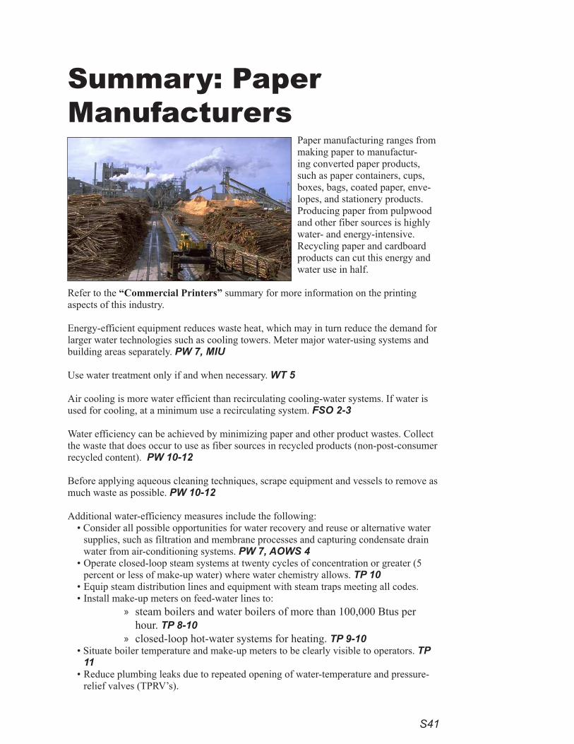
S41
Summary: Paper Manufacturers
Paper manufacturing ranges from making paper to manufactur-ing converted paper products, such as paper containers, cups, boxes, bags, coated paper, enve-lopes, and stationery products. Producing paper from pulpwood and other fiber sources is highly water- and energy-intensive. Recycling paper and cardboard products can cut this energy and water use in half.
Refer to the “Commercial Printers” summary for more information on the printing aspects of this industry.
Energy-efficient equipment reduces waste heat, which may in turn reduce the demand for larger water technologies such as cooling towers. Meter major water-using systems and building areas separately. PW 7, MIU
Use water treatment only if and when necessary. WT 5
Air cooling is more water efficient than recirculating cooling-water systems. If water is used for cooling, at a minimum use a recirculating system. FSO 2-3
Water efficiency can be achieved by minimizing paper and other product wastes. Collect the waste that does occur to use as fiber sources in recycled products (non-post-consumer recycled content). PW 10-12
Before applying aqueous cleaning techniques, scrape equipment and vessels to remove as much waste as possible. PW 10-12
Additional water-efficiency measures include the following:• Consider all possible opportunities for water recovery and reuse or alternative water
supplies, such as filtration and membrane processes and capturing condensate drain water from air-conditioning systems. PW 7, AOWS 4
• Operate closed-loop steam systems at twenty cycles of concentration or greater (5 percent or less of make-up water) where water chemistry allows. TP 10
• Equip steam distribution lines and equipment with steam traps meeting all codes.• Install make-up meters on feed-water lines to:
steam boilers and water boilers of more than 100,000 Btus per hour. TP 8-10closed-loop hot-water systems for heating. TP 9-10
• Situate boiler temperature and make-up meters to be clearly visible to operators. TP 11
• Reduce plumbing leaks due to repeated opening of water-temperature and pressure-relief valves (TPRV’s).
»
»
S42
• Make discharge pipes easy to inspect for flow and there should be visible indicators of any valve activation. RP 3, 21
Measures to improve water efficiency in water treatment include:
•for all filtration processes, installing pressure gauges to determine when to backwash or change cartridges, followed by backwash based upon pressure differential.
•for all ion-exchange and softening processes, setting recharge cycles by volume of water treated or using con-ductivity controllers.
•avoiding the use of timers for softener-recharge systems. •using water treatment only when necessary. • use a reverse osmosis and nanofiltration systems with the lowest reject rate for its size. • choose distillation equipment that recovers at least 85 percent of the feed water. WT 5
Install automatic-shutoff and solenoid valves on all hoses and water-using equipment. PW 7
Install faucets on set tubs and janitorial sinks with flows not to exceed 2.2 gpm. RP3, 14-17 Employ these floor-cleaning efficiency practices:
• Low-flow, high-pressure nozzles on hoses or water brooms used for floor and mat washing where a flow of water is needed. RP 2, 19, FSP 18-20, PW 5, 7
• Minimize the need to use a hose as a broom by installing drains close to areas where liquid discharges are expected. PW 5, 7
Use high-efficiency toilets requiring no more than 1.3 gallons per flush and urinals which flush with 1 gallon or less. Avoid automatically timed flushing systems. Use self-closing faucets with flows of 0.5 gpm for hand wash-ing. If available, and if codes and health departments permit, flush with non-potable water. RP 2, 5-9, 14-17
Conspicuously mark fire-protection plumbing so no connections will be made except for fire protection. Addition-ally, install flow-detection meters on fire services to indicate unauthorized water flows. RP 4,23
If water features or irrigated landscaping are used on a site, refer to the summary on “Water Features, Pools, and Landscapes.”
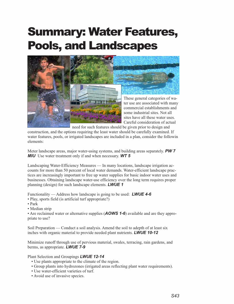
S43
Summary: Water Features, Pools, and Landscapes
These general categories of wa-ter use are associated with many commercial establishments and some industrial sites. Not all sites have all these water uses. Careful consideration of actual
need for such features should be given prior to design and construction, and the options requiring the least water should be carefully examined. If water features, pools, or irrigated landscapes are included in a plan, consider the followin elements:
Meter landscape areas, major water-using systems, and building areas separately. PW 7 MIU Use water treatment only if and when necessary. WT 5
Landscaping Water-Efficiency Measures — In many locations, landscape irrigation ac-counts for more than 50 percent of local water demands. Water-efficient landscape prac-tices are increasingly important to free up water supplies for basic indoor water uses and businesses. Obtaining landscape water-use efficiency over the long term requires proper planning (design) for such landscape elements. LWUE 1
Functionality — Address how landscape is going to be used: LWUE 4-6• Play, sports field (is artificial turf appropriate?)• Park• Median strip• Are reclaimed water or alternative supplies (AOWS 1-6) available and are they appro-priate to use?
Soil Preparation — Conduct a soil analysis. Amend the soil to adepth of at least six inches with organic material to provide needed plant nutrients. LWUE 10-12
Minimize runoff through use of pervious material, swales, terracing, rain gardens, and berms, as appropriate. LWUE 7-9
Plant Selection and Groupings LWUE 12-14• Use plants appropriate to the climate of the region.• Group plants into hydrozones (irrigated areas reflecting plant water requirements).• Use water-efficient varieties of turf.• Avoid use of invasive species.
S44
Irrigation Systems LWUE 14-19 — Irrigation systems replace water in the soil that is used by shrubs, trees, and grass, where natural moisture is inadequate for the intended landscape. The primary guideline for landscape irriga-tion design is to avoid over watering by applying the right amount of water, to the right place, at the right time.
More specific irrigation design and construction water-efficiency measures follow: • Install separate irrigation meters for landscaped areas.• Install irrigation equipment that meets the Irrigation Association design guidelines for maximum irrigation
operational uniformity.• For all new nonresidential landscapes not required to have a separate water-service meter, install a private
irrigation sub-meter and backflow prevention valve between the point of connection on the domestic water service and the first irrigation valve.
• Design for potential installation of irrigation hardware approved for reclaimed water, should it become avail-able and if appropriate.
• Design all irrigation systems to avoid runoff, overspray, low head drainage, and similar conditions. • Install a non-irrigated buffer along side areas where water flows off-site onto adjacent property, non-irrigated
areas, walks, roadways, or structures.• Employ drip or low-volume irrigation equipment in buffers and medians strips and other areas where it is
determined that overhead spray irrigation would result in waste of water due to excessive runoff or overspray.• Follow proper hydrozoning principles when designing irrigation systems to separately water turf and bedded
areas.• Install a pressure regulator if water-supply pressure exceeds 80 psi.• Match precipitation rates on sprinkler heads within a hydrozone.• Install anti-drain check valves as needed to minimize or prevent low head drainage. • Use Irrigation Association approved “smart controllers,” (have dual or multiple programming capability, mul-
tiple start times, and a percent switch, etc.) along with rain sensors, or use weather-based (ET) controllers.
Water losses occur through evaporation, splash out, backwashing the filter, and leaks.
Three elements govern good practice: • Design of the mechanical equipment to filter, clean, and operate the pool. • Design of the pool to minimize water loss. • Choosing alternatives that use less water. PSF 1
Specific water efficiency measures for water features and pools include: • Equip all pools, spas, and fountains with recirculating filtration equipment. PSF 1-6• Design ground pools with splash troughs around the perimeter that drain back into the pool. PSF 2,6• Install water meters on the make-up line. Monitor water use for abnormal flow increases that may indicate
leaks that should be identified and repaired. PSF 4,6• Use coated media filters where cost effective. PSF 3-4, 6• Use cartridge filters for smaller spas where the cost of the filters and cleaning make them economically fea-
sible. PSF 3-4, 6• For all filtration processes, install pressure gauges to determine when to backwash or change cartridges, then
backwash based upon pressure differential. WT 5• Use water treatment only when necessary. WT 5• Reuse backwash water for irrigation or re-treat the water and reuse it in the pool. PSF 3-6 • Consider alternates to pools, such as shallow spray “scapes.” PSF 4,6• Install pool covers to reduce evaporation. Retracting mechanisms promote regular use of the covers. PSF 2,6• Use shrubs or fences to shade the pool and block winds that increase evaporation. PSF 2,6
Install automatic-shutoff and solenoid valves on all hoses and water-using equipment. PW 7

Water-Using Technologies

This page intentionally left blank.
RP1
Restrooms and PlumbingEvery building with a water supply uses plumbing to convey and control the water. Plumbing fixtures are a ubiquitous part of our daily lives. Almost all build-ings used by people have at least one restroom. Examples are schools, hospitals, hotels, service stations, stores, government buildings, places of worship, office buildings, convenience stores, and entertainment sites.
Because of the large numbers of plumbing fixtures and the enormous amounts of water they collectively use, federal and California statues set water-use stan-dards for some fixtures and appliances. Manufacturers and water interests have continued to examine opportunities for water efficiency and associated energy efficiency. In addition, performance testing for some plumbing fixtures resulted in new specifications, such as the EPA WaterSense specification for high-efficiency toilets (HETs). New specifications for faucets and shower heads are being devel-oped, resulting in a series of improved products. Restroom and plumbing fixtures are prime targets for new design or retrofit with high-efficiency technologies.
Water-using technologies that have specific potential for water conservation are discussed in this section. For each technology, alternative water-efficiency meth-ods are scored “High” (better than 50 percent savings), “Medium” (10-50 percent savings), or “Low” (less than 10 percent savings) compared with standard tech-nologies. These include:
Restroom and Bathroom Fixtures• Toilets• Urinals• Showers and baths • Floor-drain trap primers
Faucets • Hand-washing lavatories • Kitchen and food-service sinks• Pre-rinse spray valves (see “Food Service – Scullery”)• Janitorial (mop) sinks• Outdoor faucets (hose-bibs)
Valves and Other Devices• Emergency shut-off valve access and isolation valves• Water-heater-temperature pressure-relief (TPRV’s) and relief valves• Pumps• Backflow preventers• Fire-protection systems• Surge tanks and other forms of potable water storage
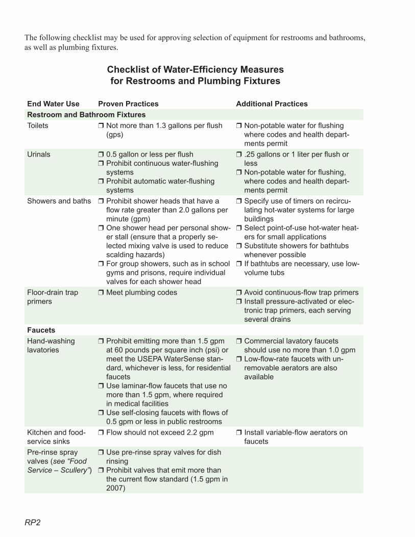
RP2
The following checklist may be used for approving selection of equipment for restrooms and bathrooms, as well as plumbing fixtures.
Checklist of Water-Efficiency Measures for Restrooms and Plumbing Fixtures
End Water Use Proven Practices Additional Practices
Restroom and Bathroom Fixtures
Toilets Not more than 1.3 gallons per flush (gps)
❒ Non-potable water for flushing where codes and health depart-ments permit
❒
Urinals 0.5 gallon or less per flushProhibit continuous water-flushing systemsProhibit automatic water-flushing systems
❒
❒
❒
.25 gallons or 1 liter per flush or lessNon-potable water for flushing, where codes and health depart-ments permit
❒
❒
Showers and baths Prohibit shower heads that have a flow rate greater than 2.0 gallons per minute (gpm)One shower head per personal show-er stall (ensure that a properly se-lected mixing valve is used to reduce scalding hazards)For group showers, such as in school gyms and prisons, require individual valves for each shower head
❒
❒
❒
Specify use of timers on recircu-lating hot-water systems for large buildingsSelect point-of-use hot-water heat-ers for small applicationsSubstitute showers for bathtubs whenever possibleIf bathtubs are necessary, use low-volume tubs
❒
❒
❒
❒
Floor-drain trap primers
Meet plumbing codes❒ Avoid continuous-flow trap primersInstall pressure-activated or elec-tronic trap primers, each serving several drains
❒
❒
Faucets
Hand-washing lavatories
Prohibit emitting more than 1.5 gpm at 60 pounds per square inch (psi) or meet the USEPA WaterSense stan-dard, whichever is less, for residential faucets Use laminar-flow faucets that use no more than 1.5 gpm, where required in medical facilitiesUse self-closing faucets with flows of 0.5 gpm or less in public restrooms
❒
❒
❒
Commercial lavatory faucets should use no more than 1.0 gpmLow-flow-rate faucets with un-removable aerators are also available
❒
❒
Kitchen and food-service sinks
Flow should not exceed 2.2 gpm❒ Install variable-flow aerators on faucets
❒
Pre-rinse spray valves (see “Food Service – Scullery”)
Use pre-rinse spray valves for dish rinsingProhibit valves that emit more than the current flow standard (1.5 gpm in 2007)
❒
❒
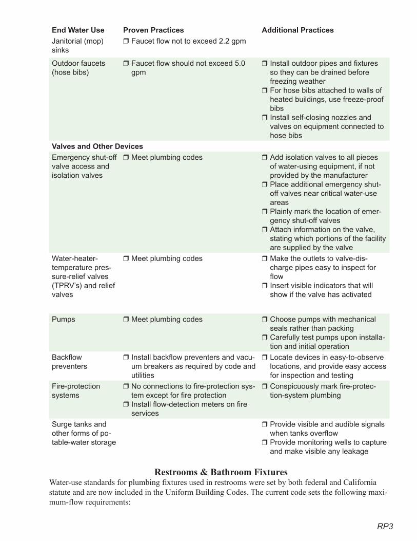
RP3
End Water Use Proven Practices Additional Practices
Janitorial (mop) sinks
Faucet flow not to exceed 2.2 gpm❒
Outdoor faucets (hose bibs)
Faucet flow should not exceed 5.0 gpm
❒ Install outdoor pipes and fixtures so they can be drained before freezing weatherFor hose bibs attached to walls of heated buildings, use freeze-proof bibsInstall self-closing nozzles and valves on equipment connected to hose bibs
❒
❒
❒
Valves and Other Devices
Emergency shut-off valve access and isolation valves
Meet plumbing codes❒ Add isolation valves to all pieces of water-using equipment, if not provided by the manufacturerPlace additional emergency shut-off valves near critical water-use areasPlainly mark the location of emer-gency shut-off valvesAttach information on the valve, stating which portions of the facility are supplied by the valve
❒
❒
❒
❒
Water-heater-temperature pres-sure-relief valves (TPRV’s) and relief valves
Meet plumbing codes❒ Make the outlets to valve-dis-charge pipes easy to inspect for flowInsert visible indicators that will show if the valve has activated
❒
❒
Pumps Meet plumbing codes❒ Choose pumps with mechanical seals rather than packingCarefully test pumps upon installa-tion and initial operation
❒
❒
Backflow preventers
Install backflow preventers and vacu-um breakers as required by code and utilities
❒ Locate devices in easy-to-observe locations, and provide easy access for inspection and testing
❒
Fire-protection systems
No connections to fire-protection sys-tem except for fire protectionInstall flow-detection meters on fire services
❒
❒
Conspicuously mark fire-protec-tion-system plumbing
❒
Surge tanks and other forms of po-table-water storage
Provide visible and audible signals when tanks overflowProvide monitoring wells to capture and make visible any leakage
❒
❒
Restrooms & Bathroom Fixtures
Water-use standards for plumbing fixtures used in restrooms were set by both federal and California statute and are now included in the Uniform Building Codes. The current code sets the following maxi-mum-flow requirements:
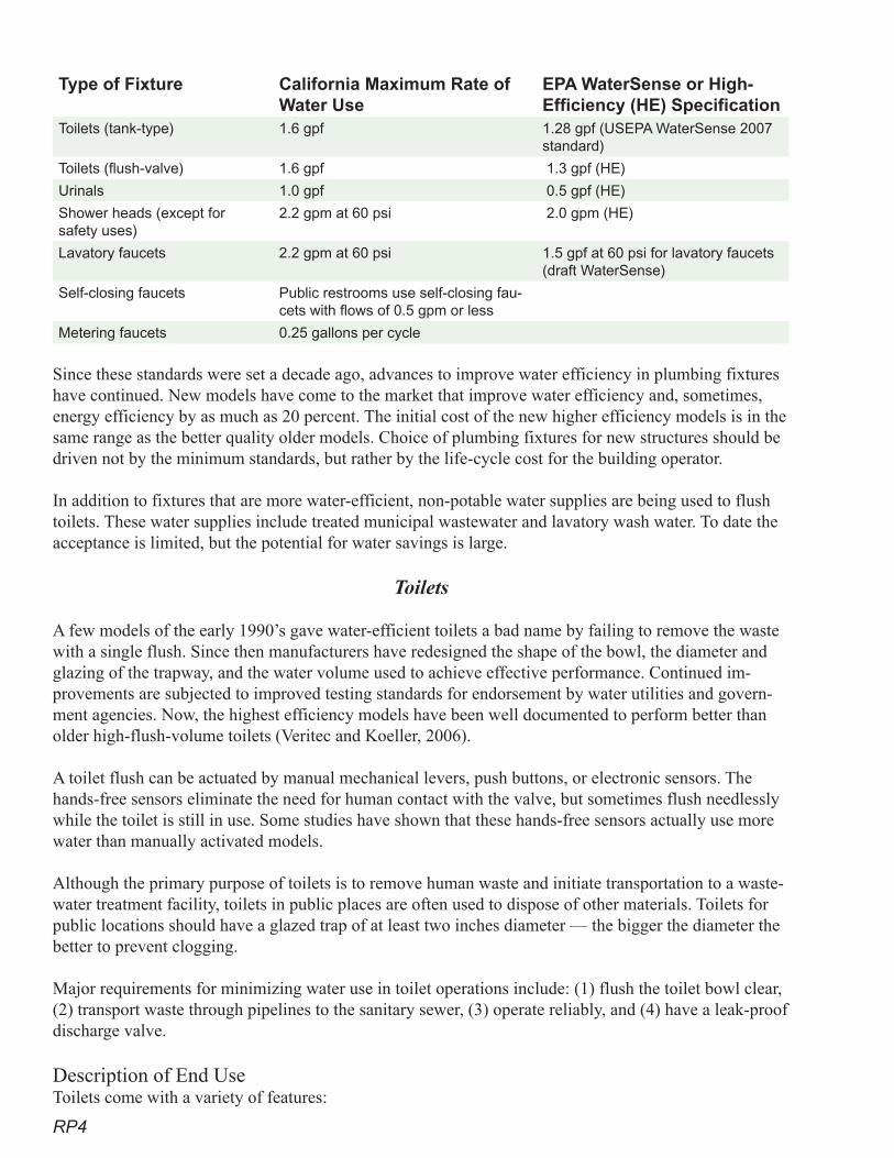
RP4
Type of Fixture California Maximum Rate of Water Use
EPA WaterSense or High- Efficiency (HE) Specification
Toilets (tank-type) 1.6 gpf 1.28 gpf (USEPA WaterSense 2007 standard)
Toilets (flush-valve) 1.6 gpf 1.3 gpf (HE)
Urinals 1.0 gpf 0.5 gpf (HE)
Shower heads (except for safety uses)
2.2 gpm at 60 psi 2.0 gpm (HE)
Lavatory faucets 2.2 gpm at 60 psi 1.5 gpf at 60 psi for lavatory faucets (draft WaterSense)
Self-closing faucets Public restrooms use self-closing fau-cets with flows of 0.5 gpm or less
Metering faucets 0.25 gallons per cycle
Since these standards were set a decade ago, advances to improve water efficiency in plumbing fixtures have continued. New models have come to the market that improve water efficiency and, sometimes, energy efficiency by as much as 20 percent. The initial cost of the new higher efficiency models is in the same range as the better quality older models. Choice of plumbing fixtures for new structures should be driven not by the minimum standards, but rather by the life-cycle cost for the building operator.
In addition to fixtures that are more water-efficient, non-potable water supplies are being used to flush toilets. These water supplies include treated municipal wastewater and lavatory wash water. To date the acceptance is limited, but the potential for water savings is large.
Toilets
A few models of the early 1990’s gave water-efficient toilets a bad name by failing to remove the waste with a single flush. Since then manufacturers have redesigned the shape of the bowl, the diameter and glazing of the trapway, and the water volume used to achieve effective performance. Continued im-provements are subjected to improved testing standards for endorsement by water utilities and govern-ment agencies. Now, the highest efficiency models have been well documented to perform better than older high-flush-volume toilets (Veritec and Koeller, 2006).
A toilet flush can be actuated by manual mechanical levers, push buttons, or electronic sensors. The hands-free sensors eliminate the need for human contact with the valve, but sometimes flush needlessly while the toilet is still in use. Some studies have shown that these hands-free sensors actually use more water than manually activated models.
Although the primary purpose of toilets is to remove human waste and initiate transportation to a waste-water treatment facility, toilets in public places are often used to dispose of other materials. Toilets for public locations should have a glazed trap of at least two inches diameter — the bigger the diameter the better to prevent clogging.
Major requirements for minimizing water use in toilet operations include: (1) flush the toilet bowl clear, (2) transport waste through pipelines to the sanitary sewer, (3) operate reliably, and (4) have a leak-proof discharge valve.
Description of End UseToilets come with a variety of features:
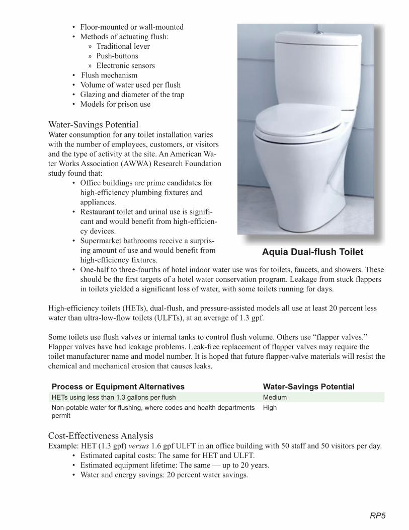
RP�
• Floor-mounted or wall-mounted • Methods of actuating flush:
Traditional lever Push-buttonsElectronic sensors
• Flush mechanism• Volume of water used per flush• Glazing and diameter of the trap• Models for prison use
Water-Savings PotentialWater consumption for any toilet installation varies with the number of employees, customers, or visitors and the type of activity at the site. An American Wa-ter Works Association (AWWA) Research Foundation study found that:
• Office buildings are prime candidates for high-efficiency plumbing fixtures and appliances.
• Restaurant toilet and urinal use is signifi-cant and would benefit from high-efficien-cy devices.
• Supermarket bathrooms receive a surpris-ing amount of use and would benefit from high-efficiency fixtures.
• One-half to three-fourths of hotel indoor water use was for toilets, faucets, and showers. These should be the first targets of a hotel water conservation program. Leakage from stuck flappers in toilets yielded a significant loss of water, with some toilets running for days.
High-efficiency toilets (HETs), dual-flush, and pressure-assisted models all use at least 20 percent less water than ultra-low-flow toilets (ULFTs), at an average of 1.3 gpf.
Some toilets use flush valves or internal tanks to control flush volume. Others use “flapper valves.” Flapper valves have had leakage problems. Leak-free replacement of flapper valves may require the toilet manufacturer name and model number. It is hoped that future flapper-valve materials will resist the chemical and mechanical erosion that causes leaks.
Process or Equipment Alternatives Water-Savings PotentialHETs using less than 1.3 gallons per flush Medium
Non-potable water for flushing, where codes and health departments permit
High
Cost-Effectiveness Analysis Example: HET (1.3 gpf) versus 1.6 gpf ULFT in an office building with 50 staff and 50 visitors per day.
• Estimated capital costs: The same for HET and ULFT.• Estimated equipment lifetime: The same — up to 20 years.• Water and energy savings: 20 percent water savings.
»»»
Aquia Dual-flush Toilet
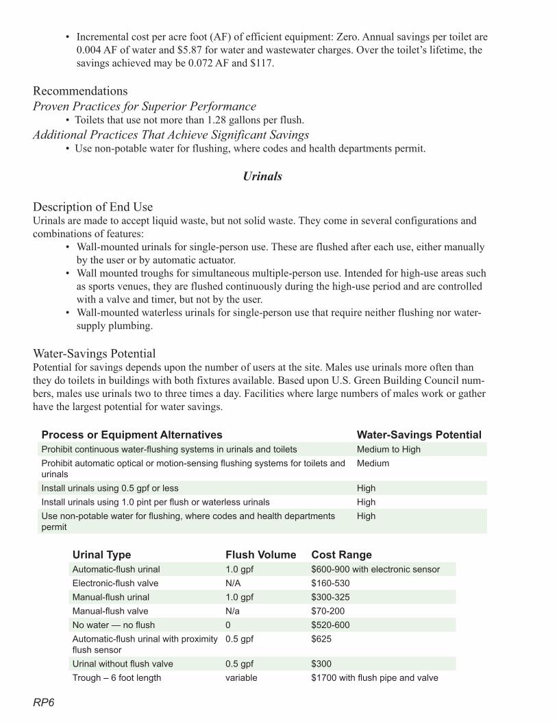
RP6
• Incremental cost per acre foot (AF) of efficient equipment: Zero. Annual savings per toilet are 0.004 AF of water and $5.87 for water and wastewater charges. Over the toilet’s lifetime, the savings achieved may be 0.072 AF and $117.
RecommendationsProven Practices for Superior Performance
• Toilets that use not more than 1.28 gallons per flush.Additional Practices That Achieve Significant Savings
• Use non-potable water for flushing, where codes and health departments permit.
Urinals
Description of End UseUrinals are made to accept liquid waste, but not solid waste. They come in several configurations and combinations of features:
• Wall-mounted urinals for single-person use. These are flushed after each use, either manually by the user or by automatic actuator.
• Wall mounted troughs for simultaneous multiple-person use. Intended for high-use areas such as sports venues, they are flushed continuously during the high-use period and are controlled with a valve and timer, but not by the user.
• Wall-mounted waterless urinals for single-person use that require neither flushing nor water-supply plumbing.
Water-Savings PotentialPotential for savings depends upon the number of users at the site. Males use urinals more often than they do toilets in buildings with both fixtures available. Based upon U.S. Green Building Council num-bers, males use urinals two to three times a day. Facilities where large numbers of males work or gather have the largest potential for water savings.
Process or Equipment Alternatives Water-Savings PotentialProhibit continuous water-flushing systems in urinals and toilets Medium to High
Prohibit automatic optical or motion-sensing flushing systems for toilets and urinals
Medium
Install urinals using 0.5 gpf or less High
Install urinals using 1.0 pint per flush or waterless urinals High
Use non-potable water for flushing, where codes and health departments permit
High
Urinal Type Flush Volume Cost RangeAutomatic-flush urinal 1.0 gpf $600-900 with electronic sensor
Electronic-flush valve N/A $160-530
Manual-flush urinal 1.0 gpf $300-325
Manual-flush valve N/a $70-200
No water — no flush 0 $520-600
Automatic-flush urinal with proximity flush sensor
0.5 gpf $625
Urinal without flush valve 0.5 gpf $300
Trough – 6 foot length variable $1700 with flush pipe and valve
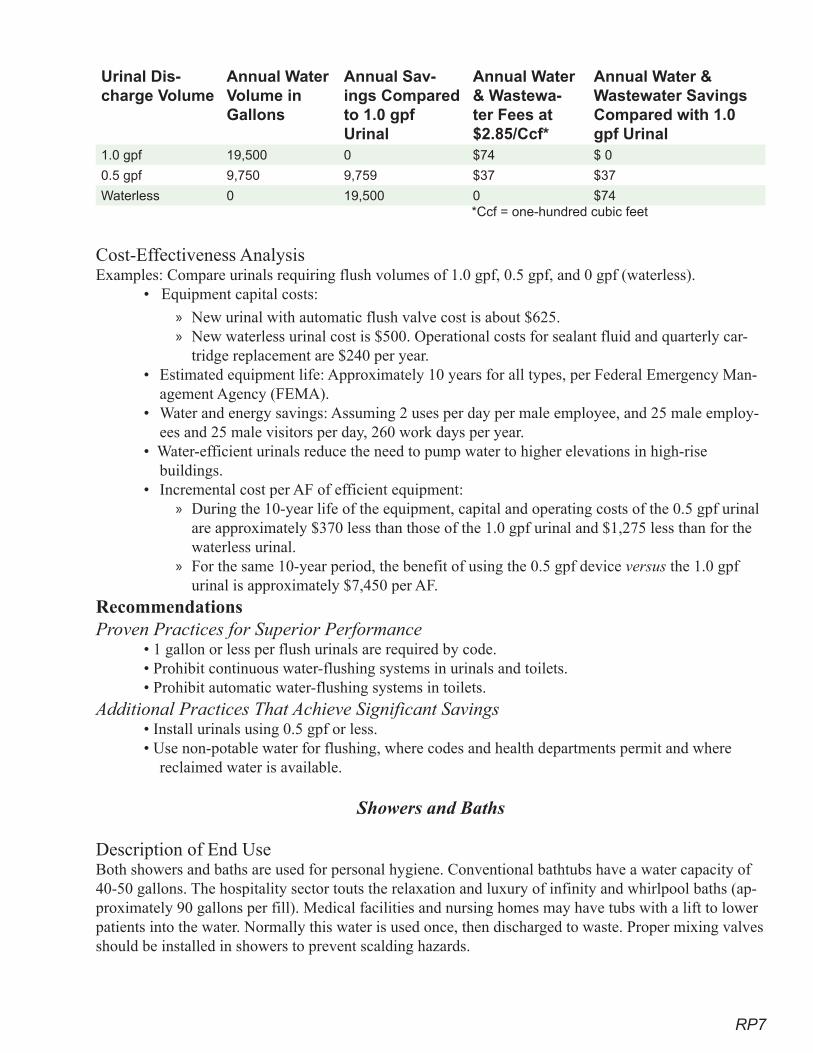
RP7
Urinal Dis-charge Volume
Annual Water Volume in Gallons
Annual Sav-ings Compared to 1.0 gpf Urinal
Annual Water & Wastewa-ter Fees at $2.85/Ccf*
Annual Water & Wastewater Savings Compared with 1.0 gpf Urinal
1.0 gpf 19,500 0 $74 $ 0
0.5 gpf 9,750 9,759 $37 $37
Waterless 0 19,500 0 $74 *Ccf = one-hundred cubic feet
Cost-Effectiveness AnalysisExamples: Compare urinals requiring flush volumes of 1.0 gpf, 0.5 gpf, and 0 gpf (waterless).
• Equipment capital costs:
New urinal with automatic flush valve cost is about $625.New waterless urinal cost is $500. Operational costs for sealant fluid and quarterly car-tridge replacement are $240 per year.
• Estimated equipment life: Approximately 10 years for all types, per Federal Emergency Man-agement Agency (FEMA).
• Water and energy savings: Assuming 2 uses per day per male employee, and 25 male employ-ees and 25 male visitors per day, 260 work days per year.
• Water-efficient urinals reduce the need to pump water to higher elevations in high-rise buildings.
• Incremental cost per AF of efficient equipment: During the 10-year life of the equipment, capital and operating costs of the 0.5 gpf urinal are approximately $370 less than those of the 1.0 gpf urinal and $1,275 less than for the waterless urinal. For the same 10-year period, the benefit of using the 0.5 gpf device versus the 1.0 gpf urinal is approximately $7,450 per AF.
RecommendationsProven Practices for Superior Performance
• 1 gallon or less per flush urinals are required by code.• Prohibit continuous water-flushing systems in urinals and toilets.• Prohibit automatic water-flushing systems in toilets.
Additional Practices That Achieve Significant Savings• Install urinals using 0.5 gpf or less.• Use non-potable water for flushing, where codes and health departments permit and where
reclaimed water is available.
Showers and Baths
Description of End UseBoth showers and baths are used for personal hygiene. Conventional bathtubs have a water capacity of 40-50 gallons. The hospitality sector touts the relaxation and luxury of infinity and whirlpool baths (ap-proximately 90 gallons per fill). Medical facilities and nursing homes may have tubs with a lift to lower patients into the water. Normally this water is used once, then discharged to waste. Proper mixing valves should be installed in showers to prevent scalding hazards.
»»
»
»

RP8
Hot tubs are also popular. The water (several hundred gallons) is often circulated through filters and heaters. Disinfectants are added manually or in the recirculation cycle. When not in use, they should be covered to reduce loss of heat and water.
Shower heads are available with a variety of spray patterns, water-droplet sizes, and pulsations. Both shower and bathtub water are used and typically discharged to sanitary wastewater. In locker rooms and similar situations, several people may wash in a communal shower room with multiple shower heads. Tubs come in various sizes. The use of standard-size tubs should be recommended, since they hold, and therefore use, less water.
Excluded from this discussion are shower heads required for emergency cleaning of personnel due to chemical and other contamination.
Water-Savings PotentialChoose shower heads that perform well, are vandal- and tamper-proof, and limit flow to 2.0 or less gpm (at 60 psi) collectively for all shower heads in the shower stall. In locker-room showers, flow to each shower head should be controlled individually by the user.
Select shallower bathtubs that have smaller water capacity. The water level will cover the bather when immersed.
In the hospitality sector, hot water is often circulated from a water heater, through a pipeline loop, to the guest rooms. Unused water returns to the water heater. This provides hot water quickly to the guest showers/baths and reduces the water wasted while waiting for warm water. The circulated hot water should be placed on a timer (may increase energy use).
Where plumbing code and health officials allow, the wastewater from showers and baths may be cap-tured, treated, and redirected for toilet flushing or other non-potable, non-contact uses.
Process or Equipment Alternatives Water-Savings PotentialUse shower heads that allow not more than 2.0 gpm 3.5 gallons/shower
Install only one shower head per personal shower stall 30 gallons/shower
Install individual valves for each shower head in a gang-type shower Medium
Specify recirculating hot-water systems for large buildings High
Select point-of-use hot-water heaters for small applications Medium
Substitute showers for bathtubs whenever possible 20 gallons/shower
If bathtubs are necessary, use low-volume tubs 15 gallons
RecommendationsProven Practices for Superior Performance
• Use shower heads that allow flow of not more than 2.0 gpm.• Install only one shower head per personal shower stall.• For group showers, install individual valves to control each shower head.
Additional Practices That Achieve Significant Savings• Specify recirculating hot-water systems for large buildings.• Select point-of-use hot-water heaters for small applications (do not use on recirculating lines
or at the far end of the water line).• Substitute showers for bathtubs whenever possible.• If bathtubs are necessary, use low-volume tubs.
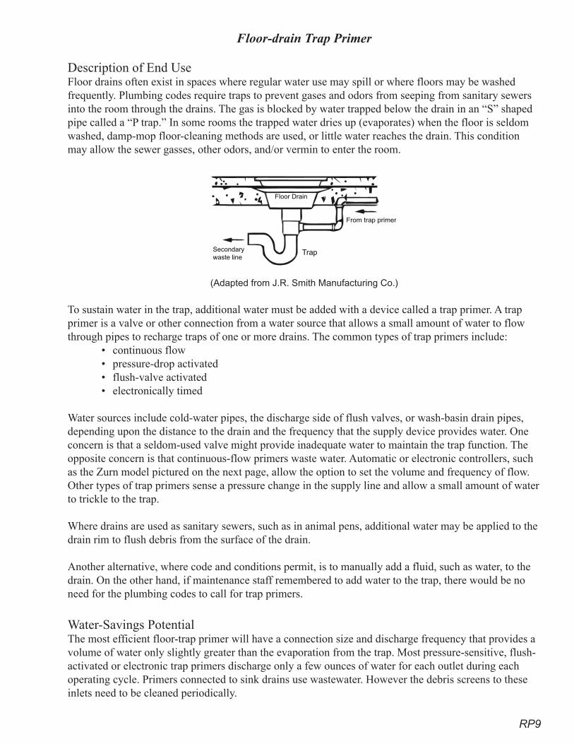
RP9
Floor-drain Trap Primer
Description of End UseFloor drains often exist in spaces where regular water use may spill or where floors may be washed frequently. Plumbing codes require traps to prevent gases and odors from seeping from sanitary sewers into the room through the drains. The gas is blocked by water trapped below the drain in an “S” shaped pipe called a “P trap.” In some rooms the trapped water dries up (evaporates) when the floor is seldom washed, damp-mop floor-cleaning methods are used, or little water reaches the drain. This condition may allow the sewer gasses, other odors, and/or vermin to enter the room.
(Adapted from J.R. Smith Manufacturing Co.)
To sustain water in the trap, additional water must be added with a device called a trap primer. A trap primer is a valve or other connection from a water source that allows a small amount of water to flow through pipes to recharge traps of one or more drains. The common types of trap primers include:
• continuous flow • pressure-drop activated • flush-valve activated• electronically timed
Water sources include cold-water pipes, the discharge side of flush valves, or wash-basin drain pipes, depending upon the distance to the drain and the frequency that the supply device provides water. One concern is that a seldom-used valve might provide inadequate water to maintain the trap function. The opposite concern is that continuous-flow primers waste water. Automatic or electronic controllers, such as the Zurn model pictured on the next page, allow the option to set the volume and frequency of flow. Other types of trap primers sense a pressure change in the supply line and allow a small amount of water to trickle to the trap.
Where drains are used as sanitary sewers, such as in animal pens, additional water may be applied to the drain rim to flush debris from the surface of the drain.
Another alternative, where code and conditions permit, is to manually add a fluid, such as water, to the drain. On the other hand, if maintenance staff remembered to add water to the trap, there would be no need for the plumbing codes to call for trap primers.
Water-Savings PotentialThe most efficient floor-trap primer will have a connection size and discharge frequency that provides a volume of water only slightly greater than the evaporation from the trap. Most pressure-sensitive, flush-activated or electronic trap primers discharge only a few ounces of water for each outlet during each operating cycle. Primers connected to sink drains use wastewater. However the debris screens to these inlets need to be cleaned periodically.
From trap primer
TrapSecondary
waste line
Floor Drain
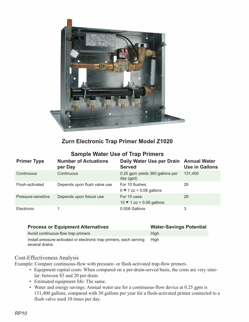
RP10
Zurn Electronic Trap Primer Model Z1020
Sample Water Use of Trap PrimersPrimer Type Number of Actuations
per DayDaily Water Use per Drain Served
Annual Water Use in Gallons
Continuous Continuous 0.25 gpm yields 360 gallons per day (gpd)
131,400
Flush-activated Depends upon flush valve use For 10 flushes:
0 × 1 oz = 0.08 gallons
28
Pressure-sensitive Depends upon fixture use For 10 uses:
10 × 1 oz = 0.08 gallons
28
Electronic 1 0.008 Gallons 3
Process or Equipment Alternatives Water-Savings PotentialAvoid continuous-flow trap primers High
Install pressure-activated or electronic trap primers, each serving several drains
High
Cost-Effectiveness Analysis Example: Compare continuous-flow with pressure- or flush-activated trap-flow primers.
• Equipment capital costs: When compared on a per-drain-served basis, the costs are very simi-lar: between $5 and 20 per drain.
• Estimated equipment life: The same.• Water and energy savings: Annual water use for a continuous-flow device at 0.25 gpm is
131,400 gallons, compared with 30 gallons per year for a flush-activated primer connected to a flush valve used 10 times per day.
RP11
• Incremental cost per AF of efficient equipment: Water and wastewater fee savings (at $2.85 per Ccf) for 131,370 gallons is $783 per year or $1942 per AF.
RecommendationsProven Practices for Superior Performance
• Meet plumbing code.Additional Practices That Achieve Significant Savings
• Avoid continuous-flow trap primers.• Install pressure-activated or electronic trap primers, each serving several drains.
Faucets
Faucets are valves operated by people for indoor purposes. Outdoor hand-operated valves are known as hose bibs.
Hand-Washing Lavatories
Description of End UseSeveral types of faucets offer different flow durations and flow rates:
• Manually operated faucets require someone to open the valve and to close the valve.• Self-closing faucets run as long as the user holds the handle in the open position. Once re-
leased, the spring-loaded faucet closes itself. • Metering faucets are actuated manually or automatically. They deliver a preset amount of
water (some models deliver 0.25 gallons during a 5- to 10-second cycle; others models have cycles that can be set to 45 seconds) before shutting off. Operating conditions, such as water pressure, temperature, and flow rate, may affect the timing cycle. Some manufacturers provide a 5-year warranty.
• Automatic faucets sense the proximity of the user and start the flow of water, which is main-tained while the user is within sensor range. Then the faucet shuts itself off.
• Drinking-water bubblers operate with self-closing faucets.
Aerators may be added to faucets to entrain air, reduce splash, and reduce the water flow. Common aerator flow rates are 0.5, 1, and 2.2 gpm. An aerator is a circular screen disk attached to the end of the faucet. Vandal- and tamper-proof aerators should be installed in non-residential buildings. Aerators with manual flow adjustment are available for kitchen faucets.
Because aerators entrain air which may contain pathogens into the water stream, and the pathogens may reside on the internal aerator screens, aerators should not be used in medical facilities. California regula-tions prohibit aerator use in hospitals, but laminar-flow restrictors may be used to prevent splash and re-duce flow without air entrainment. Other aerators should be replaced or at least cleaned every few years.
Water-Savings Potential• For public restrooms, hand washing for personal hygiene needs a minor flow rate to lubricate
the soap, flush grime and bacteria from the skin, and rinse soap from the hands. • For motel and hotel guest-room bathrooms, the wash basin is used for various hygiene and
grooming purposes. The U.S. Environmental Protection Agency (USEPA) WaterSense pro-gram reports that flows of no more than 1.5 gallons per minute are adequate.
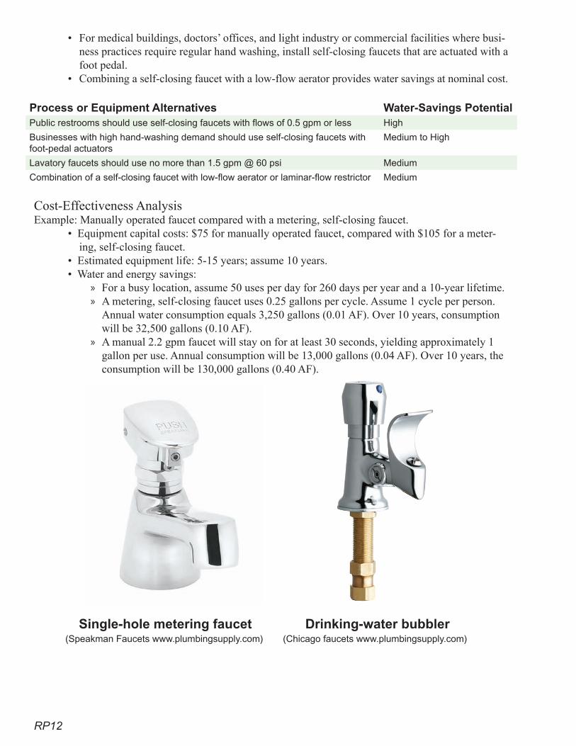
RP12
• For medical buildings, doctors’ offices, and light industry or commercial facilities where busi-ness practices require regular hand washing, install self-closing faucets that are actuated with a foot pedal.
• Combining a self-closing faucet with a low-flow aerator provides water savings at nominal cost.
Process or Equipment Alternatives Water-Savings PotentialPublic restrooms should use self-closing faucets with flows of 0.5 gpm or less High
Businesses with high hand-washing demand should use self-closing faucets with foot-pedal actuators
Medium to High
Lavatory faucets should use no more than 1.5 gpm @ 60 psi Medium
Combination of a self-closing faucet with low-flow aerator or laminar-flow restrictor Medium
Cost-Effectiveness Analysis Example: Manually operated faucet compared with a metering, self-closing faucet.
• Equipment capital costs: $75 for manually operated faucet, compared with $105 for a meter-ing, self-closing faucet.
• Estimated equipment life: 5-15 years; assume 10 years.• Water and energy savings:
For a busy location, assume 50 uses per day for 260 days per year and a 10-year lifetime. A metering, self-closing faucet uses 0.25 gallons per cycle. Assume 1 cycle per person. Annual water consumption equals 3,250 gallons (0.01 AF). Over 10 years, consumption will be 32,500 gallons (0.10 AF).A manual 2.2 gpm faucet will stay on for at least 30 seconds, yielding approximately 1 gallon per use. Annual consumption will be 13,000 gallons (0.04 AF). Over 10 years, the consumption will be 130,000 gallons (0.40 AF).
»»
»
Single-hole metering faucet Drinking-water bubbler (Speakman Faucets www.plumbingsupply.com) (Chicago faucets www.plumbingsupply.com)
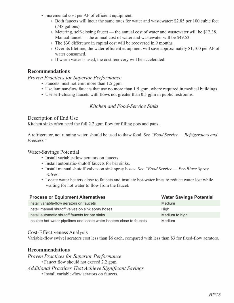
RP13
• Incremental cost per AF of efficient equipment: Both faucets will incur the same rates for water and wastewater: $2.85 per 100 cubic feet (748 gallons).Metering, self-closing faucet — the annual cost of water and wastewater will be $12.38. Manual faucet — the annual cost of water and wastewater will be $49.53. The $30 difference in capital cost will be recovered in 9 months. Over its lifetime, the water-efficient equipment will save approximately $1,100 per AF of water consumed. If warm water is used, the cost recovery will be accelerated.
RecommendationsProven Practices for Superior Performance
• Faucets must not emit more than 1.5 gpm. • Use laminar-flow faucets that use no more than 1.5 gpm, where required in medical buildings.• Use self-closing faucets with flows not greater than 0.5 gpm in public restrooms.
Kitchen and Food-Service Sinks
Description of End UseKitchen sinks often need the full 2.2 gpm flow for filling pots and pans.
A refrigerator, not running water, should be used to thaw food. See “Food Service — Refrigerators and Freezers.”
Water-Savings Potential• Install variable-flow aerators on faucets.• Install automatic-shutoff faucets for bar sinks.• Install manual shutoff valves on sink spray hoses. See “Food Service — Pre-Rinse Spray
Valves.”• Locate water heaters close to faucets and insulate hot-water lines to reduce water lost while
waiting for hot water to flow from the faucet.
Process or Equipment Alternatives Water Savings PotentialInstall variable-flow aerators on faucets Medium
Install manual shutoff valves on sink spray hoses High
Install automatic shutoff faucets for bar sinks Medium to high
Insulate hot-water pipelines and locate water heaters close to faucets Medium
Cost-Effectiveness Analysis Variable-flow swivel aerators cost less than $6 each, compared with less than $3 for fixed-flow aerators.
RecommendationsProven Practices for Superior Performance
• Faucet flow should not exceed 2.2 gpm.Additional Practices That Achieve Significant Savings
• Install variable-flow aerators on faucets.
»
»
»»
»
RP14
Pre-Rinse Spray Valves – See “Food Service – Scullery”
Janitorial (Mop) Sinks
Description of End UseLarge wash basins or set tubs used for janitorial purposes provide water to multi-gallon containers for floor cleaning and mops. Large flows of 2.2 gpm are desired. Sometimes hoses are connected from the faucets to minimize splash and spills to the wash buckets.
Water-Savings PotentialCare exercised by the user will help to achieve water savings.
RecommendationsProven Practices for Superior Performance
• Faucet flow should not exceed 2.2 gallons per minute.
Outdoor Faucets
Description of End UseOutdoor faucets, often known as hose bibs, sill cocks, water spigots, or hose hydrants, are valves which are often threaded to allow easy connection to hoses, pressure washers, and other equipment. Not subject to the 2.2 gpm flow limitation, flows through hose bibs are determined by the equipment being used.
Water-Savings PotentialFor hose bibs where vandalism and unauthorized use is a concern, use a “loose key.” Instead of an at-tached handle, there is a slot for a removable square key to be used to operate the hose bib. Alternatively, provide a locked box over the hose bib or eliminate hose bibs.
Prevent water waste from broken pipes and fixtures during freezing conditions:• Install pipes so they can be drained before freezing occurs.• For hose bibs attached to walls of heated buildings, use freeze-proof bibs that extend through
the wall into a warm environment.• Insulate pipes and plumbing attachments and add heat tape for seasonal use. • Backflow preventers, meters, and all similar devices should be freeze-resistant and installed so
as to guard against freezing.
Equipment, especially hoses, connected to hose bibs should all have self-closing nozzles.
Process or Equipment Alternatives Water-Savings PotentialUse a “loose key” for hose bibs to reduce vandalism Medium
For freezing climates, install outdoor pipes and fixtures so they can be drained before freezing weather
High
For freezing climates, use freeze-proof bibs to attach to walls of heated buildings
High
Install self-closing nozzles and valves on equipment connected to hose bibs High
Cost-Effectiveness Analysis Most of these recommendations can be achieved with minimal, if any, extra costs.
RP1�
Example: regular hose bibs compared with freeze-proof hose bibs. • Equipment capital costs: Minimal $4 versus $37 for a freeze-proof bib. • Estimated equipment life: More than 5 years with washer replacements.• Water and energy savings: Water savings may be achieved, but no wastewater savings.• Incremental cost per AF of efficient equipment: N/A.
RecommendationsProven Practices for Superior Performance
• Faucet flow should not exceed 2.2 gpm. Additional Practices That Achieve Significant Savings
• Use a “loose key” for hose bibs to reduce vandalism.• Install outdoor pipes and fixtures so they can be drained before freezing weather.• Use freeze-proof hose bibs when attached to walls of heated buildings.• Install self-closing nozzles and valves on equipment connected to hose bibs.
Valves and Other Devices
Devices listed in this section are used to limit losses during pipe ruptures, equipment failures, and other emergencies. Unlike much of the other equipment and processes described in this guide, these devices do not readily lend themselves to cost-effectiveness analysis. These controls may be inactive for many months or even years, then their function is immediate. In the meantime, small leaks or overflows may occur. Locate these devices to be easily seen, so leaks may be noted and corrective repairs performed.
Emergency Shutoff Valve and Isolation Valve Accessibility
Description of End UseEmergency shutoff valves can be used to stop water flow when pipes rupture, connections leak, or equipment fails. During repairs, isolation valves can stop flows to individual pieces of equipment, while avoiding shutting down water to major portions of a building.
Water-Savings PotentialShutoff valves are relatively cheap compared with the potential damage they can minimize. Their useful-ness relates to how well they are marked and their accessibility. Never block access, and plainly mark the location of emergency shutoff valves near the valve site and in the area where the water is used.
If not supplied by the manufacturer, add an isolation valve to each piece of water-using equipment.
Process or Equipment Alternatives Water-Savings PotentialAdd isolation valves to all pieces of water-using equipment if not provided by the manufacturer
Low
Place additional emergency shutoff valves near critical water-use areas Low
Plainly mark the location of emergency shutoff valves Low
Attach information on the valve stating which portions of the facility are supplied by the valve
Low
RecommendationsProven Practices for Superior Performance
• None.
RP16
Additional Practices That Achieve Significant Savings• Add isolation valves to all pieces of water-using equipment if not provided by the manufacturer.• Place additional emergency shutoff valves near critical water-use areas.• Plainly mark the location of emergency shutoff valves.• Attach information on the valve stating which portions of the facility are supplied by the valve.
Water-heater-temperature Pressure-relief Valves (TPRV’s) and Relief Valves
Description of End UseLocated on the upper portion of the water tank, this valve prevents the build-up of hazardous pressure by releasing water to an overflow pipe. Water-supply pressure should be within the range recommended by appliance and equipment manufacturers — usually 40 to 60 psi.
Water-Savings PotentialFlows from the valve discharge pipe should be easy to observe. Place visible indictors to show when the valves are actuated and operations need to be corrected.
Process or Equipment Alternatives Water-Savings PotentialMake valve discharge pipes easy to inspect for flow Medium
Insert visible indicators that will show if the valve has activated Low
RecommendationsProven Practices for Superior Performance
• None.Additional Practices That Achieve Significant Savings
• Make the outlets to valve discharge pipes easy to inspect for flow.• Insert visible indicators that will show if the valve has activated.
.Pumps
Description of End UsePumps are used with many fluids and gasses. Our focus is leakage that may occur from pumps used to move water and to increase water pressure.
Water-Savings PotentialSome vacuum pumps used in health-care facilities use water seals to avoid oil-vapor contamination of the vacuum lines. Choose newer vacuum pumps that do not use water seals. Choose pumps that are air-cooled. If a water-cooled pump is needed, do not use single-pass water-cooling systems. Instead, cool the pump motor with a cooling-water loop. See “Thermodynamic Processes.”
Pumps with packing glands have a reputation for leaks and frequent need for replacing the packing. Me-chanical seals are superior to packing glands in that they are far less likely to fail and leak.
Process or Equipment Alternatives Water-Savings PotentialChoose pumps with mechanical seals rather than packing High
Carefully test pumps upon installation and initial operation to ensure leak-free operation
Medium
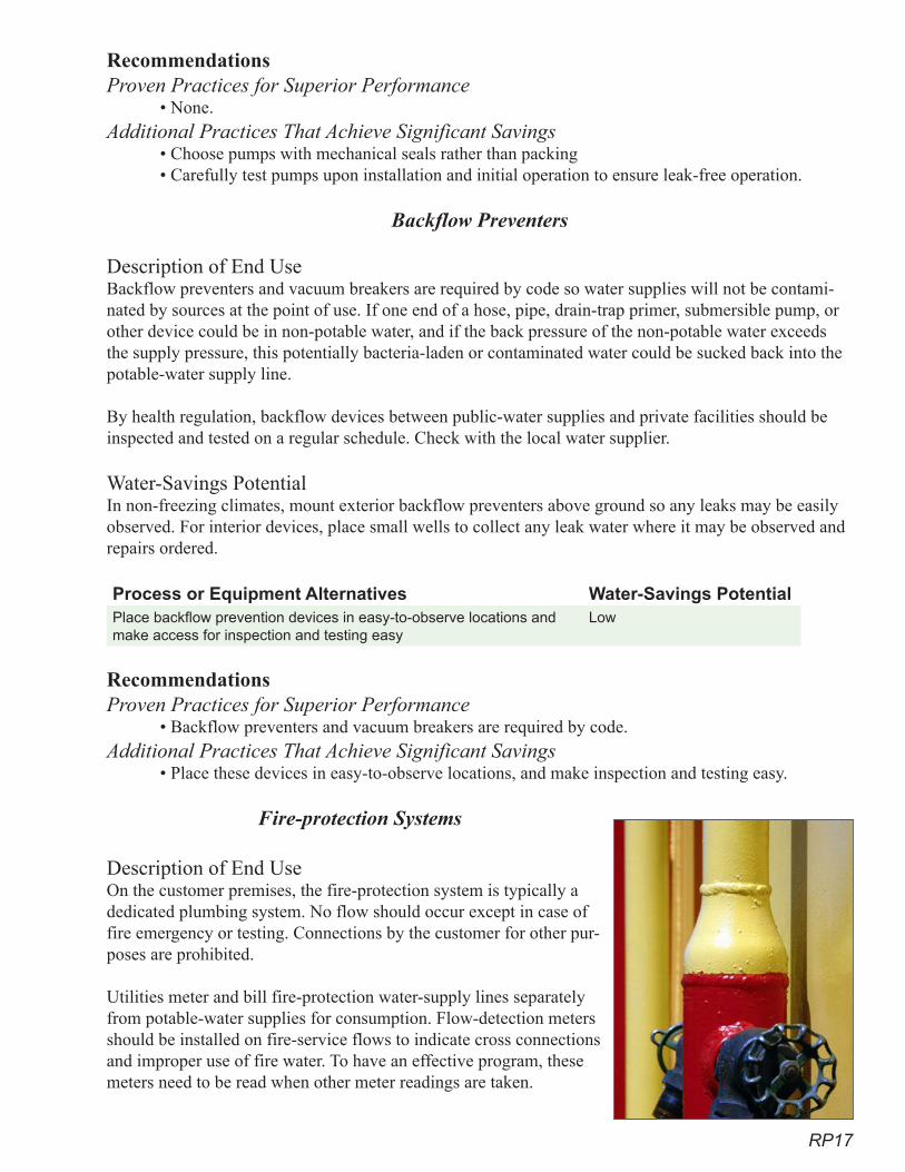
RP17
RecommendationsProven Practices for Superior Performance
• None.Additional Practices That Achieve Significant Savings
• Choose pumps with mechanical seals rather than packing • Carefully test pumps upon installation and initial operation to ensure leak-free operation.
Backflow Preventers
Description of End UseBackflow preventers and vacuum breakers are required by code so water supplies will not be contami-nated by sources at the point of use. If one end of a hose, pipe, drain-trap primer, submersible pump, or other device could be in non-potable water, and if the back pressure of the non-potable water exceeds the supply pressure, this potentially bacteria-laden or contaminated water could be sucked back into the potable-water supply line.
By health regulation, backflow devices between public-water supplies and private facilities should be inspected and tested on a regular schedule. Check with the local water supplier.
Water-Savings PotentialIn non-freezing climates, mount exterior backflow preventers above ground so any leaks may be easily observed. For interior devices, place small wells to collect any leak water where it may be observed and repairs ordered.
Process or Equipment Alternatives Water-Savings PotentialPlace backflow prevention devices in easy-to-observe locations and make access for inspection and testing easy
Low
RecommendationsProven Practices for Superior Performance
• Backflow preventers and vacuum breakers are required by code.Additional Practices That Achieve Significant Savings
• Place these devices in easy-to-observe locations, and make inspection and testing easy.
Fire-protection Systems
Description of End UseOn the customer premises, the fire-protection system is typically a dedicated plumbing system. No flow should occur except in case of fire emergency or testing. Connections by the customer for other pur-poses are prohibited.
Utilities meter and bill fire-protection water-supply lines separately from potable-water supplies for consumption. Flow-detection meters should be installed on fire-service flows to indicate cross connections and improper use of fire water. To have an effective program, these meters need to be read when other meter readings are taken.
RP18
Water-Savings PotentialTo avoid any cross connections between fire-protection and water-supply plumbing, mark fire-protec-tion plumbing conspicuously. Install flow indicators to show the presence of leaks. Utilities may require flow-check meters capable of detecting small flows (less than 1 gpm) on the fire-supply line. Process or Equipment Alternatives Water-Savings PotentialAllow no connections to fire-protection systems except for fire protection
Place flow-detection meters on fire services High
Conspicuously mark fire-protection-system plumbing Low
Recommendations Proven Practices for Superior Performance
• Allow no connections to fire-protection systems except for fire protection.• Place flow-detection meters on fire services.
Additional Practices That Achieve Significant Savings• Conspicuously mark fire-protection-system plumbing.
Surge Tanks and Other Forms of Potable-water Storage
Description of End UseStorage tanks may be placed atop high-rise buildings to maintain pressure in the building.
Surge tanks absorb the pressure transients (water hammer) of fast-acting valves to reduce plumbing-sys-tem damage. Expansion tanks and pressure-relief tanks are safety devices to store expanded heated water and relieve pressure on the plumbing system.
Water-Savings PotentialTanks and their fittings sometimes leak only intermittently when water pressure is higher. An obser-vation well or collection basin can collect the leakage and provide visible evidence of the leak. Then repairs can be taken.
Altitude-control valves are supposed to sense the level of water in the tank and stop inflow if the storage level exceeds a specified elevation. If the altitude-control valve fails, the tank may overflow with great loss of water and sometimes property damage. The overflow is usually channeled through a pipe to a drain. Install a signal device to show that overflow has occurred.
Process or Equipment Alternatives Water-Savings PotentialProvide discharge-flow monitors to record evidence and signal when tanks overflow
High
Provide monitoring wells to capture and make visible any leakage Low
RecommendationsProven Practices for Superior Performance
• None.Additional Practices That Achieve Significant Savings
• Provide visible and audible signals when tanks overflow. • Provide monitoring wells to capture and make any leakage visible.
RP19
ReferencesCalifornia Urban Water Conservation Council. 2001. The CII ULFT Savings Study.
Chicago Faucet. Chicago Faucet Maintenance and Repair Manual. www.chicagofaucets.com/Re-pair_Manual_Wkr.pdf.
East Bay Municipal Utility District. EBMUD Toilet Rebate program.
Hansen, Rob. Zurn Plumbing, personal communication, and internet site www.zurn.com.
New Mexico. Office of the State Engineer. 1999. A Water Conservation Guide for Commercial Insti-tutional and Industrial Users.
Plumbing products internet sites:www.nextag.comwww.plumbingstore.comwww.sloan.comwww.americanstandard-us.comwww.plumbingproducts.comwww.mifab.com
Pacific Northwest National Laboratory. 2005. Update of Market Assessment for Capturing Water Conservation Opportunities in the Federal Sector.
U.S. Federal Energy Management Program. www.eere.energy.gov/femp/procurement/eep_toilets_uri-nals_calc.cfm.
U.S. Environmental Protection Agency. WaterSense Program. 2007. High-Efficiency Bathroom Sink Faucet Specification.
U.S. Environmental Protection Agency. WaterSense Program. www.epa.gov/WaterSense/.
Veritec Consulting Inc. November 2006. Koeller and Company, Maximum Performance (MaP) Test-ing of Popular Toilets. Vickers, A. 2001. Water Use and Conservation.

RP20
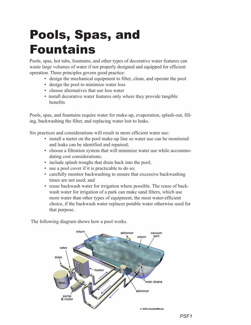
PSF1
Pools, spas, hot tubs, fountains, and other types of decorative water features can waste large volumes of water if not properly designed and equipped for efficient operation. Three principles govern good practice:
• design the mechanical equipment to filter, clean, and operate the pool • design the pool to minimize water loss• choose alternatives that use less water• install decorative water features only where they provide tangible
benefits
Pools, spas, and fountains require water for make-up, evaporation, splash-out, fill-ing, backwashing the filter, and replacing water lost to leaks.
Six practices and considerations will result in more efficient water use:• install a meter on the pool make-up line so water use can be monitored
and leaks can be identified and repaired;• choose a filtration system that will minimize water use while accommo-
dating cost considerations;• include splash troughs that drain back into the pool; • use a pool cover if it is practicable to do so;• carefully monitor backwashing to ensure that excessive backwashing
times are not used; and• reuse backwash water for irrigation where possible. The reuse of back-
wash water for irrigation of a park can make sand filters, which use more water than other types of equipment, the most water-efficient choice, if the backwash water replaces potable water otherwise used for that purpose.
The following diagram shows how a pool works.
Pools, Spas, and Fountains
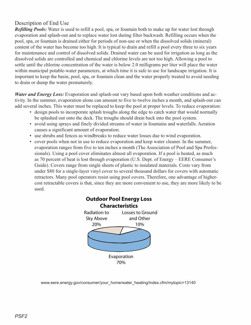
PSF2
Description of End UseRefilling Pools: Water is used to refill a pool, spa, or fountain both to make up for water lost through evaporation and splash-out and to replace water lost during filter backwash. Refilling occurs when the pool, spa, or fountain is drained either for periods of non-use or when the dissolved solids (mineral) content of the water has become too high. It is typical to drain and refill a pool every three to six years for maintenance and control of dissolved solids. Drained water can be used for irrigation as long as the dissolved solids are controlled and chemical and chlorine levels are not too high. Allowing a pool to settle until the chlorine concentration of the water is below 2.0 milligrams per liter will place the water within municipal potable-water parameters, at which time it is safe to use for landscape irrigation. It is important to keep the basin, pool, spa, or fountain clean and the water properly treated to avoid needing to drain or dump the water prematurely.
Water and Energy Loss: Evaporation and splash-out vary based upon both weather conditions and ac-tivity. In the summer, evaporation alone can amount to five to twelve inches a month, and splash-out can add several inches. This water must be replaced to keep the pool at proper levels. To reduce evaporation:
• design pools to incorporate splash troughs along the edge to catch water that would normally be splashed out onto the deck. The troughs should drain back into the pool system.
• avoid using sprays and finely divided streams of water in fountains and waterfalls. Aeration causes a significant amount of evaporation.
• use shrubs and fences as windbreaks to reduce water losses due to wind evaporation.• cover pools when not in use to reduce evaporation and keep water cleaner. In the summer,
evaporation ranges from five to ten inches a month (The Association of Pool and Spa Profes-sionals). Using a pool cover eliminates almost all evaporation. If a pool is heated, as much as 70 percent of heat is lost through evaporation (U.S. Dept. of Energy – EERE Consumer’s Guide). Covers range from single sheets of plastic to insulated materials. Costs vary from under $80 for a single-layer vinyl cover to several thousand dollars for covers with automatic retractors. Many pool operators resist using pool covers. Therefore, one advantage of higher-cost retractable covers is that, since they are more convenient to use, they are more likely to be used.
www.eere.energy.gov/consumer/your_home/water_heating/index.cfm/mytopic=13140
Evaporation70%
Radiation toSky Above
20%
Losses to Groundand Other
10%
Outdoor Pool Energy LossCharacteristics
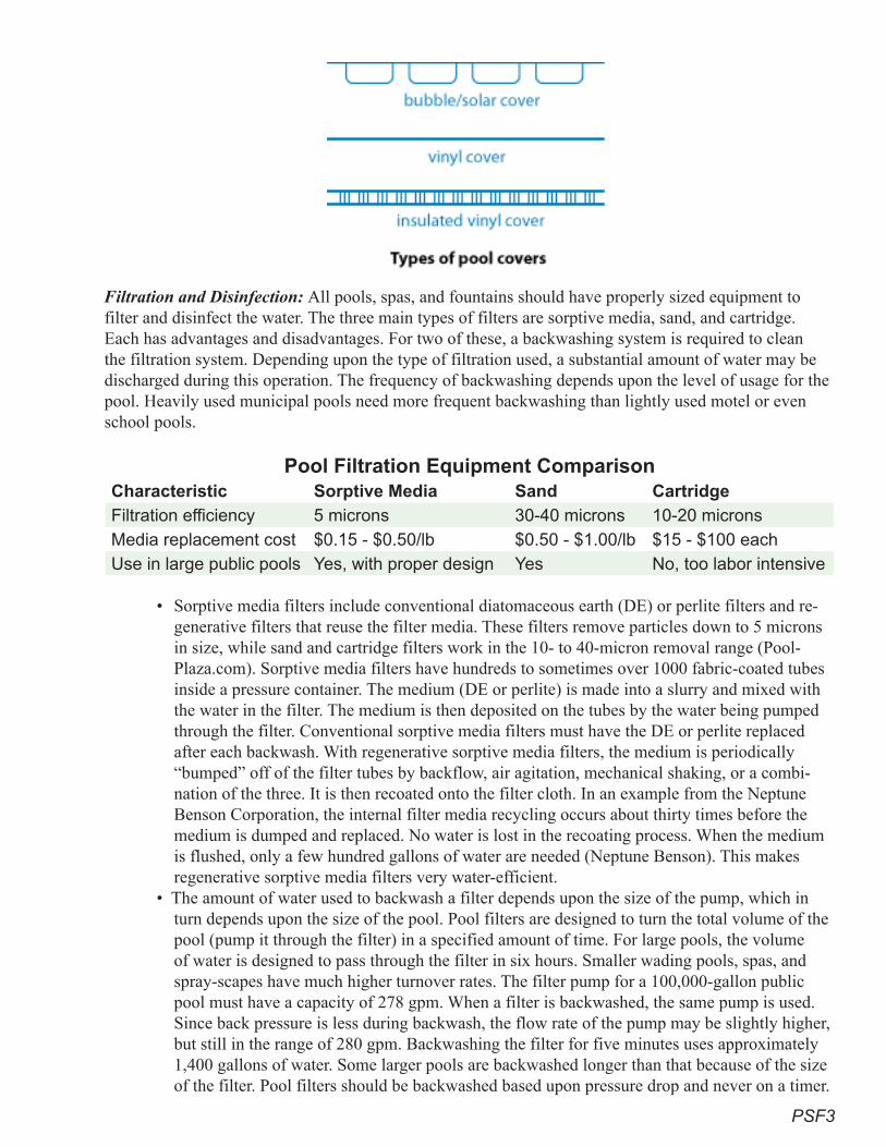
PSF3
Filtration and Disinfection: All pools, spas, and fountains should have properly sized equipment to filter and disinfect the water. The three main types of filters are sorptive media, sand, and cartridge. Each has advantages and disadvantages. For two of these, a backwashing system is required to clean the filtration system. Depending upon the type of filtration used, a substantial amount of water may be discharged during this operation. The frequency of backwashing depends upon the level of usage for the pool. Heavily used municipal pools need more frequent backwashing than lightly used motel or even school pools.
Pool Filtration Equipment ComparisonCharacteristic Sorptive Media Sand CartridgeFiltration efficiency 5 microns 30-40 microns 10-20 micronsMedia replacement cost $0.15 - $0.50/lb $0.50 - $1.00/lb $15 - $100 eachUse in large public pools Yes, with proper design Yes No, too labor intensive
• Sorptive media filters include conventional diatomaceous earth (DE) or perlite filters and re-generative filters that reuse the filter media. These filters remove particles down to 5 microns in size, while sand and cartridge filters work in the 10- to 40-micron removal range (Pool-Plaza.com). Sorptive media filters have hundreds to sometimes over 1000 fabric-coated tubes inside a pressure container. The medium (DE or perlite) is made into a slurry and mixed with the water in the filter. The medium is then deposited on the tubes by the water being pumped through the filter. Conventional sorptive media filters must have the DE or perlite replaced after each backwash. With regenerative sorptive media filters, the medium is periodically “bumped” off of the filter tubes by backflow, air agitation, mechanical shaking, or a combi-nation of the three. It is then recoated onto the filter cloth. In an example from the Neptune Benson Corporation, the internal filter media recycling occurs about thirty times before the medium is dumped and replaced. No water is lost in the recoating process. When the medium is flushed, only a few hundred gallons of water are needed (Neptune Benson). This makes regenerative sorptive media filters very water-efficient.
• The amount of water used to backwash a filter depends upon the size of the pump, which in turn depends upon the size of the pool. Pool filters are designed to turn the total volume of the pool (pump it through the filter) in a specified amount of time. For large pools, the volume of water is designed to pass through the filter in six hours. Smaller wading pools, spas, and spray-scapes have much higher turnover rates. The filter pump for a 100,000-gallon public pool must have a capacity of 278 gpm. When a filter is backwashed, the same pump is used. Since back pressure is less during backwash, the flow rate of the pump may be slightly higher, but still in the range of 280 gpm. Backwashing the filter for five minutes uses approximately 1,400 gallons of water. Some larger pools are backwashed longer than that because of the size of the filter. Pool filters should be backwashed based upon pressure drop and never on a timer.
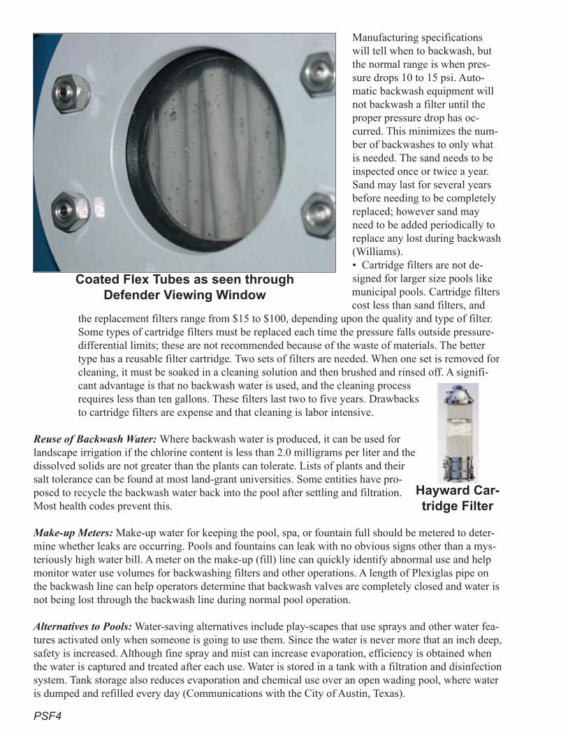
PSF4
Manufacturing specifications will tell when to backwash, but the normal range is when pres-sure drops 10 to 15 psi. Auto-matic backwash equipment will not backwash a filter until the proper pressure drop has oc-curred. This minimizes the num-ber of backwashes to only what is needed. The sand needs to be inspected once or twice a year. Sand may last for several years before needing to be completely replaced; however sand may need to be added periodically to replace any lost during backwash (Williams). • Cartridge filters are not de-signed for larger size pools like municipal pools. Cartridge filters cost less than sand filters, and
the replacement filters range from $15 to $100, depending upon the quality and type of filter. Some types of cartridge filters must be replaced each time the pressure falls outside pressure-differential limits; these are not recommended because of the waste of materials. The better type has a reusable filter cartridge. Two sets of filters are needed. When one set is removed for cleaning, it must be soaked in a cleaning solution and then brushed and rinsed off. A signifi-cant advantage is that no backwash water is used, and the cleaning process requires less than ten gallons. These filters last two to five years. Drawbacks to cartridge filters are expense and that cleaning is labor intensive.
Reuse of Backwash Water: Where backwash water is produced, it can be used for landscape irrigation if the chlorine content is less than 2.0 milligrams per liter and the dissolved solids are not greater than the plants can tolerate. Lists of plants and their salt tolerance can be found at most land-grant universities. Some entities have pro-posed to recycle the backwash water back into the pool after settling and filtration. Most health codes prevent this.
Make-up Meters: Make-up water for keeping the pool, spa, or fountain full should be metered to deter-mine whether leaks are occurring. Pools and fountains can leak with no obvious signs other than a mys-teriously high water bill. A meter on the make-up (fill) line can quickly identify abnormal use and help monitor water use volumes for backwashing filters and other operations. A length of Plexiglas pipe on the backwash line can help operators determine that backwash valves are completely closed and water is not being lost through the backwash line during normal pool operation.
Alternatives to Pools: Water-saving alternatives include play-scapes that use sprays and other water fea-tures activated only when someone is going to use them. Since the water is never more that an inch deep, safety is increased. Although fine spray and mist can increase evaporation, efficiency is obtained when the water is captured and treated after each use. Water is stored in a tank with a filtration and disinfection system. Tank storage also reduces evaporation and chemical use over an open wading pool, where water is dumped and refilled every day (Communications with the City of Austin, Texas).
Hayward Car-tridge Filter
Coated Flex Tubes as seen through Defender Viewing Window
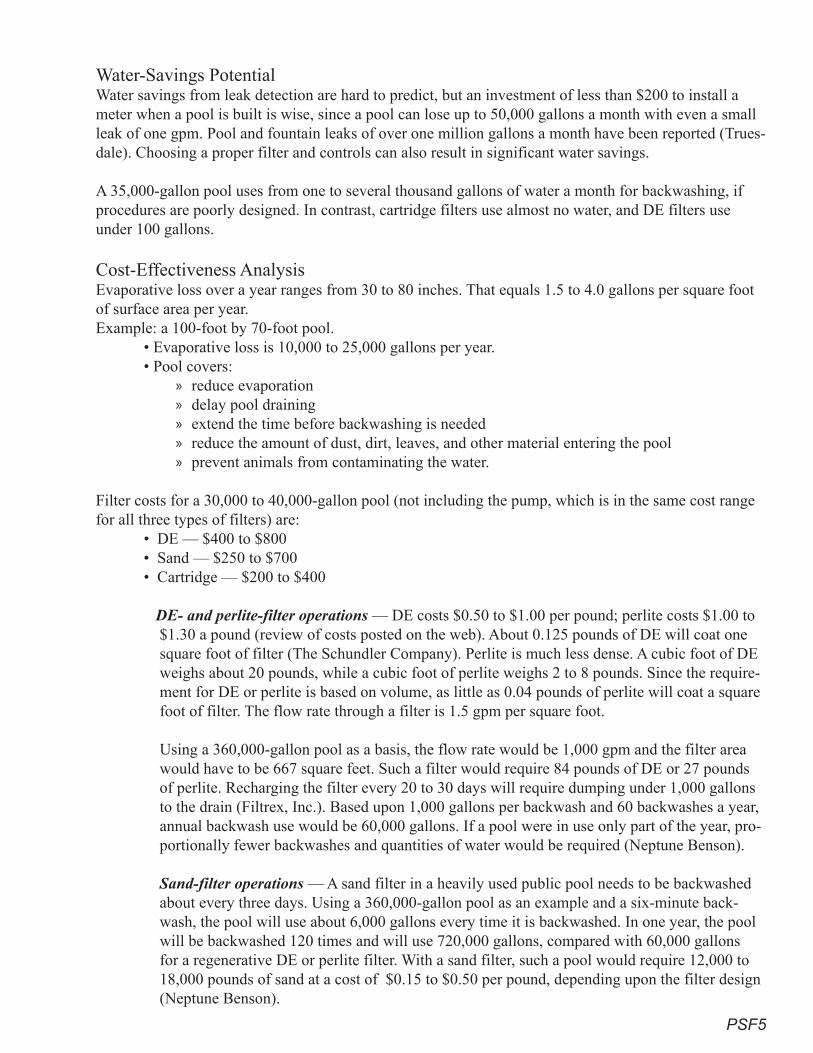
PSF�
Water-Savings PotentialWater savings from leak detection are hard to predict, but an investment of less than $200 to install a meter when a pool is built is wise, since a pool can lose up to 50,000 gallons a month with even a small leak of one gpm. Pool and fountain leaks of over one million gallons a month have been reported (Trues-dale). Choosing a proper filter and controls can also result in significant water savings.
A 35,000-gallon pool uses from one to several thousand gallons of water a month for backwashing, if procedures are poorly designed. In contrast, cartridge filters use almost no water, and DE filters use under 100 gallons.
Cost-Effectiveness Analysis Evaporative loss over a year ranges from 30 to 80 inches. That equals 1.5 to 4.0 gallons per square foot of surface area per year. Example: a 100-foot by 70-foot pool. • Evaporative loss is 10,000 to 25,000 gallons per year. • Pool covers:
reduce evaporationdelay pool draining extend the time before backwashing is neededreduce the amount of dust, dirt, leaves, and other material entering the pool prevent animals from contaminating the water.
Filter costs for a 30,000 to 40,000-gallon pool (not including the pump, which is in the same cost range for all three types of filters) are:
• DE — $400 to $800• Sand — $250 to $700• Cartridge — $200 to $400 DE- and perlite-filter operations — DE costs $0.50 to $1.00 per pound; perlite costs $1.00 to
$1.30 a pound (review of costs posted on the web). About 0.125 pounds of DE will coat one square foot of filter (The Schundler Company). Perlite is much less dense. A cubic foot of DE weighs about 20 pounds, while a cubic foot of perlite weighs 2 to 8 pounds. Since the require-ment for DE or perlite is based on volume, as little as 0.04 pounds of perlite will coat a square foot of filter. The flow rate through a filter is 1.5 gpm per square foot.
Using a 360,000-gallon pool as a basis, the flow rate would be 1,000 gpm and the filter area would have to be 667 square feet. Such a filter would require 84 pounds of DE or 27 pounds of perlite. Recharging the filter every 20 to 30 days will require dumping under 1,000 gallons to the drain (Filtrex, Inc.). Based upon 1,000 gallons per backwash and 60 backwashes a year, annual backwash use would be 60,000 gallons. If a pool were in use only part of the year, pro-portionally fewer backwashes and quantities of water would be required (Neptune Benson).
Sand-filter operations — A sand filter in a heavily used public pool needs to be backwashed about every three days. Using a 360,000-gallon pool as an example and a six-minute back-wash, the pool will use about 6,000 gallons every time it is backwashed. In one year, the pool will be backwashed 120 times and will use 720,000 gallons, compared with 60,000 gallons for a regenerative DE or perlite filter. With a sand filter, such a pool would require 12,000 to 18,000 pounds of sand at a cost of $0.15 to $0.50 per pound, depending upon the filter design (Neptune Benson).
»»»»»
PSF6
Filter cartridges cost from $15 to $100, depending upon the quality and type of filter. Typical life is 2 to 5 years, with the better (more expensive) filters lasting longer. Many cartridge-filter elements are needed per filter system for a large pool, and several filter systems are needed. Adding labor costs to hand-clean cartridge filters renders them not cost-effective for public pools, although they may be appropriate for small motel or apartment pools (PoolPlaza).
Recommendations Proven Practices for Superior Performance
• Require all pools, spas, and fountains to be equipped with recirculating filtration equipment.• Require in-ground pools to be built with splash troughs around the perimeter. • Require make-up meters to be installed on all pools.
Additional Practices That Achieve Significant Savings• Use sorptive media filters where possible for all pools, spas, and fountains.• Use cartridge filters for smaller spas, where the costs of filters and cleaning make them eco-
nomically feasible.• Reuse backwash water for irrigation or consider retreatment and reuse in the pool.• Consider use of alternatives to wading pools, such as spray-scapes.• Use pool covers, especially during periods when a pool is not in regular use.• Use shrubs or fences to shade pools and block winds that increase evaporation.
ReferencesCalifornia. 2003. Code of Regulations, Chapter 20 – Public Pools.
De Haan, William, and Johanningsmeier, Julie S. 1977. Michigan Category 5A exam on swimming pool management. Michigan State University, Ann Arbor, Michigan.
Fawcett, Paul. Clear Vision. USA Swimming (1 Olympic Plaza, Colorado Springs, Colorado).
Filtrex, Inc. (P.O. Box 2273, Wayne, New Jersey, 07474). Precoat Media Fact Sheet, IS 5887 A.
Harris, Tom. “How Swimming Pools Work.” HowStuffWorks (One Capital City Plaza, 3350 Peachtree Road, Suite 1500, Atlanta, Georgia 30326). HowStuffWorks.com.
Hoffman, H.W. 2006. Water Efficient Equipment and Design: A Guide for Non-residential Con-struction and Development. City of Austin, Texas. Austin Water Utility.
Neptune Benson (6 Jefferson Drive, Coventry, Rhode Island 02816). Defender Automatic Regenera-tive Filter. Neptunebenson.com.
Northeast Spa & Pool Association (300J Campus Drive, Morganville, New Jersey 07751). www.nespapool.org/pdf/industry_pdf/facts_pool_water_usage.pdf.
PoolPlaza.com (10500 Metric Drive, Dallas, Texas). Filter Comparison Chart.
Schundler Company, The (P.O. Box 513 Metuchen, New Jersey 08840). 1997. Swimming Pool Guide.
PSF7
Stachecki, Julie, DeHaan, William. 1997. Michigan Category 5A exam on swimming pool manage-ment. University of Michigan. East Lansing, Michigan. www.pested.msu.edu/Resources/bulletins/pdf/2621/E2621chap8.pdf.
Truesdale, Pat. 2002. Cases in Water Conservation. U.S. Environmental Protection Agency.
U.S. Department of Energy. EERE. Swimming Pool Covers. www.eere.energy.gov/consumer/your_home/water_heating/index.cfm/mytopic=13140.
U.S. Department of the Army. 1986. Repairs and Utilities: Swimming Pool Operation and Mainte-nance. TM–5-662.
Williams, Kent. 2006. Contact the Pumproom Tech (PO Box 164, New Castle, California 95658). [email protected].

PSF8
This page intentionally left blank
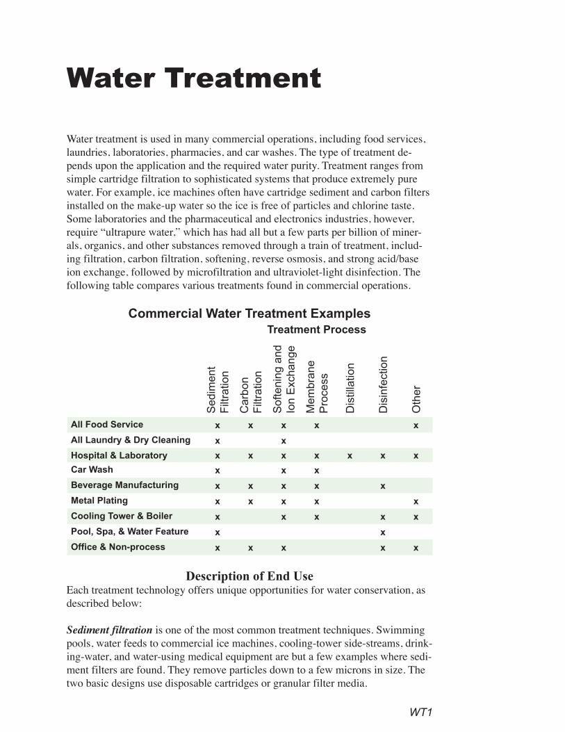
WT1
Water Treatment
Water treatment is used in many commercial operations, including food services, laundries, laboratories, pharmacies, and car washes. The type of treatment de-pends upon the application and the required water purity. Treatment ranges from simple cartridge filtration to sophisticated systems that produce extremely pure water. For example, ice machines often have cartridge sediment and carbon filters installed on the make-up water so the ice is free of particles and chlorine taste. Some laboratories and the pharmaceutical and electronics industries, however, require “ultrapure water,” which has had all but a few parts per billion of miner-als, organics, and other substances removed through a train of treatment, includ-ing filtration, carbon filtration, softening, reverse osmosis, and strong acid/base ion exchange, followed by microfiltration and ultraviolet-light disinfection. The following table compares various treatments found in commercial operations.
Commercial Water Treatment ExamplesTreatment Process
Sed
imen
t F
iltra
tion
Car
bon
Filt
ratio
n
Sof
teni
ng a
nd
Ion
Exc
hang
e
Mem
bran
e P
roce
ss
Dis
tilla
tion
Dis
infe
ctio
n
Oth
er
All Food Service x x x x x
All Laundry & Dry Cleaning x x
Hospital & Laboratory x x x x x x x
Car Wash x x x
Beverage Manufacturing x x x x x
Metal Plating x x x x x
Cooling Tower & Boiler x x x x x
Pool, Spa, & Water Feature x x
Office & Non-process x x x x x
Description of End UseEach treatment technology offers unique opportunities for water conservation, as described below:
Sediment filtration is one of the most common treatment techniques. Swimming pools, water feeds to commercial ice machines, cooling-tower side-streams, drink-ing-water, and water-using medical equipment are but a few examples where sedi-ment filters are found. They remove particles down to a few microns in size. The two basic designs use disposable cartridges or granular filter media.
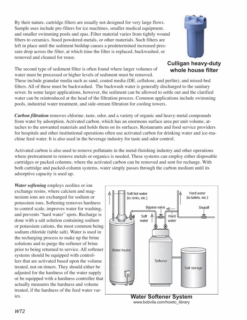
WT2
By their nature, cartridge filters are usually not designed for very large flows. Sample uses include pre-filters for ice machines, smaller medical equipment, and smaller swimming pools and spas. Filter material varies from tightly wound fibers to ceramics, fused powdered-metals, or other materials. Such filters are left in place until the sediment buildup causes a predetermined increased pres-sure drop across the filter, at which time the filter is replaced, backwashed, or removed and cleaned for reuse.
The second type of sediment filter is often found where larger volumes of water must be processed or higher levels of sediment must be removed. These include granular media such as sand, coated media (DE, cellulose, and perlite), and mixed-bed filters. All of these must be backwashed. The backwash water is generally discharged to the sanitary sewer. In some larger applications, however, the sediment can be allowed to settle out and the clarified water can be reintroduced at the head of the filtration process. Common applications include swimming pools, industrial water treatment, and side-stream filtration for cooling towers.
Carbon filtration removes chlorine, taste, odor, and a variety of organic and heavy-metal compounds from water by adsorption. Activated carbon, which has an enormous surface area per unit volume, at-taches to the unwanted materials and holds them on its surfaces. Restaurants and food service providers for hospitals and other institutional operations often use activated carbon for drinking water and ice-ma-chine feed water. It is also used in the beverage industry for taste and odor control.
Activated carbon is also used to remove pollutants in the metal-finishing industry and other operations where pretreatment to remove metals or organics is needed. These systems can employ either disposable cartridges or packed columns, where the activated carbon can be removed and sent for recharge. With both cartridge and packed-column systems, water simply passes through the carbon medium until its adsorptive capacity is used up.
Water softening employs zeolites or ion exchange resins, where calcium and mag-nesium ions are exchanged for sodium or potassium ions. Softening removes hardness to control scale, improves water for washing, and prevents “hard water” spots. Recharge is done with a salt solution containing sodium or potassium cations, the most common being sodium chloride (table salt). Water is used in the recharging process to make up the brine solutions and to purge the softener of brine prior to being returned to service. All softener systems should be equipped with control-lers that are activated based upon the volume treated, not on timers. They should either be adjusted for the hardness of the water supply or be equipped with a hardness controller that actually measures the hardness and volume treated, if the hardness of the feed water var-ies. Water Softener System
www.bobvila.com/howto_library
Culligan heavy-duty whole house filter
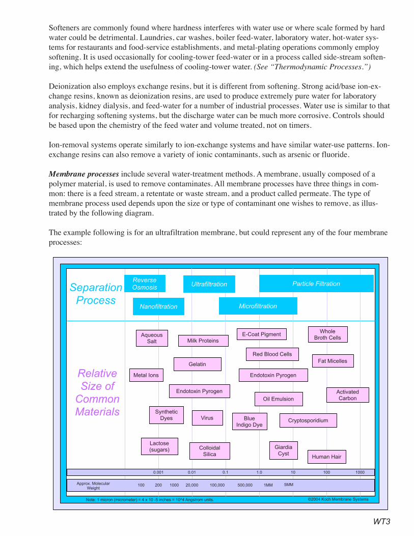
WT3
Softeners are commonly found where hardness interferes with water use or where scale formed by hard water could be detrimental. Laundries, car washes, boiler feed-water, laboratory water, hot-water sys-tems for restaurants and food-service establishments, and metal-plating operations commonly employ softening. It is used occasionally for cooling-tower feed-water or in a process called side-stream soften-ing, which helps extend the usefulness of cooling-tower water. (See “Thermodynamic Processes.”)
Deionization also employs exchange resins, but it is different from softening. Strong acid/base ion-ex-change resins, known as deionization resins, are used to produce extremely pure water for laboratory analysis, kidney dialysis, and feed-water for a number of industrial processes. Water use is similar to that for recharging softening systems, but the discharge water can be much more corrosive. Controls should be based upon the chemistry of the feed water and volume treated, not on timers.
Ion-removal systems operate similarly to ion-exchange systems and have similar water-use patterns. Ion-exchange resins can also remove a variety of ionic contaminants, such as arsenic or fluoride.
Membrane processes include several water-treatment methods. A membrane, usually composed of a polymer material, is used to remove contaminates. All membrane processes have three things in com-mon: there is a feed stream, a retentate or waste stream, and a product called permeate. The type of membrane process used depends upon the size or type of contaminant one wishes to remove, as illus-trated by the following diagram.
The example following is for an ultrafiltration membrane, but could represent any of the four membrane processes:
ReverseOsmosis
Nanofiltration
Ultrafiltration
Microfiltration
Particle FiltrationSeparation
Process
Relative
Size of
Common
Materials
AqueousSalt Milk Proteins
E-Coat PigmentWhole
Broth Cells
Fat Micelles
Red Blood Cells
Gelatin
Metal Ions
Endotoxin Pyrogen
Endotoxin Pyrogen
ActivatedCarbonOil Emulsion
SyntheticDyes Virus Blue
Indigo DyeCryptosporidium
Lactose(sugars) Colloidal
Silica
GiardiaCyst
Human Hair
0.001 0.01 0.1 1.0 10 100 1000
Approx. MolecularWeight
100 200 1000 20,000 100,000 500,000 1MM 5MM
Note: 1 micron (micrometer) = 4 x 10 -5 inches = 10^4 Angstrom units. ©2004 Koch Membrane Systems

WT4
• Microfiltration employs membranes that remove particles of 0.1 to 10 microns in size or larger. It is used in municipal water treatment to remove bacte-rial and Giardia lamblia cysts, and Cryptosporidium oocysts. Water is forced through the membrane until the pressure drop reaches a set point. The filter is then backwashed. The membranes also require periodic chemical cleaning. Both the backwash and cleaning processes use water. Retentate or waste volumes are usually a small percentage of the total feed volume. The retentate is often recirculated and only a small stream of “bleed water” is discharged as wastewater. Some ceramic filters can also filter in this range.
• Ultrafiltration operates at higher pressures than micro-filtration and removes materials that are much smaller, including viruses and proteins. It is often used to separate milk and whey. These filters must be backwashed and cleaned in a manner similar to microfiltration membranes.
• Nanofiltration membranes have pore sizes midway between those of ultrafiltration and reverse osmosis. Nanofilters are often referred to as “softening” filters, since they are effective in removing multivalent cations such as calcium and magnesium.
• Reverse osmosis (RO) removes salts from a water stream. It finds use wherever very pure wa-ter is needed, such as laboratories, medical uses including kidney dialysis, metal plating, boiler feed-water, and a number of related applications. Typically, RO will reject 90 to 95 percent of the salts. RO is also used before strong acid/base deionization for the production of ultrapure water for laboratory, pharmaceutical, and microelectronics manufacturing operations.
Distillation, a process once in common use to make water for laboratory applications, is still found in many laboratories. Electric or gas stills are used. Production quantity depends upon the size of the still. Smaller stills often use once-through condenser water and can waste huge volumes of water to produce a single gallon of distillate. Small and medium size stills use air to cool the coils and have no discharge. These are the most water-efficient stills. Some larger stills have reject streams to prevent scale buildup. These typically dump 15 to 25 percent of the water entering the still.
Disinfection and other technologies can consume small amounts of water, if chemicals are fed in a liquid or slurry form. Chemical disinfection technologies include use of chlorine compounds, ozone, and hydrogen peroxide, as well as pH control with acids and bases and the addition of antiscalants and sequestrates such as sodium hexameta phosphate. Ultraviolet light, heat, and extreme mechanical sheer are among other technologies in use.
It is important to examine disinfection requirements. Ultraviolet light, heat, and mechanical sheer pro-cesses do not use water. Other processes use water to make up the solutions, but this becomes part of the product water and is not lost. However, cleaning chemical storage areas does consume water. The poten-tial for water savings by choosing among disinfection technologies is not great; however, the potential to waste water in cleaning the equipment and storage vessels is a concern which use of waterless methods can lessen.
Water-Savings PotentialThe first water-saving possibility for water treatment is to question the need for additional treatment. If treatment is cost-effective, choose methods that need the least amount of cleaning and backwash or that
Permeate/Feed-Stream/ Retentate Diagram Koch Membrane Systems www.kochmembrane.com
WT�
have reject streams. All membrane processes produce a reject stream, which in the case of nanofiltration and reverse osmosis might be reusable.
Cost-Effectiveness Analysis Cost analysis depends upon many variables. Equipment costs for water treatment processes vary from tens to hundreds of thousands of dollars. For select industries, some level of purified water is essential to operation and is an unavoidable cost. Since many variables are involved in analyzing water-treatment alternatives, a cost-benefit analysis, including the cost of energy, should be conducted for each applica-tion to determine the most feasible water-treatment option.
RecommendationsProven Practices for Superior Performance
•For all filtration processes, require pressure gauges to determine when to backwash or change cartridges.
•For all filtration processes, base backwash upon pressure differential.•For all ion-exchange and softening processes, require recharge cycles to be set by volume of
water treated or based upon conductivity controllers.•Require that all softeners be recharged based upon the amount of water they process (demand-
based) or by actual measurement of the grains of hardness removed.Additional Practices That Achieve Significant Savings
• Use water treatment only when necessary.• Choose a reverse-osmosis or nanofiltration system with the lowest reject rate for its size.• Choose distillation equipment that recovers at least 85 percent of the feed water.• Evaluate opportunities to reuse backwash waste streams.
ReferencesAPS Water Services Corporation. www.apswater.com/.
Barnstead International (2555 Kerper Boulevard, Dubuque, Iowa USA 52001-1478.). Classic Electri-cally Heated Stills — Operations Manual.
Doulton USA (19541 Cherry Hill Rd., Southfield, MI 48076). www.doultonusa.com/.
Gibbs, Eric L., Ph.D. July 2001. Preparation of Reagent Water — Design of Laboratory Water Stills. High = Q, Inc. www.high-q.com/articles.html.
Hoffman, H. W. (Bill), and Sutton, John T. 2003. State Energy Conservation Office Suggested Water Efficiency Guidelines for Buildings and Equipment at State Facilities. Texas State Energy Con-servation Office. Austin, Texas.
Hoffman, H. W. (Bill). March 2006. Building Reduced Water and Wastewater Cost into the Design. Austin Water Utility. Austin, Texas.
Klenck, Thomas. How Softeners Work. Ahdorma Water Filters Purification and Treatment (320 Ro-bling St., #401, Brooklyn, New York). www.thewatersite.com/how_they_work_water_softeners.htm.
Koch Membrane Systems. www.kochmembrane.com.
WT6
Loretitsch, Gary. Guidelines for Managing Water in Cooling Systems: For Owners, Operators, and Environmental Engineers. Puckorius & Associates. San Jose/Santa Clara Water Pollution Control Plant.
Makini, Byron. Fall 2005. Achieving Zero Liquid Discharge in the Semiconductor Industry. Colum-bia University, Department of Earth and Environmental Engineering. New York, New York.
McDermit, Kery. August 10, 2006. RO System Helps Unilever Reduce Water Usage. Water and Wastewater.com
McIntyre, James P. August 1998. Industrial Water Reuse and Wastewater Minimization. BetzDear-borne.
Neptune Benson, Defender Automatic Regenerative Filter (6 Jefferson Drive, Coventry, Rhode Island 02816). Neptunebenson.com.
North Carolina Department of Environment and Natural Resources, Division of Pollution Prevention. August 1998. Water Efficiency Manual for Commercial, Industrial, and Institutional Facilities.
Pacific Northwest Pollution Prevention Research Center. Pollution Prevention Technology Profile: Conductivity Controls in Water Rinsing, Cooling.
Thompson, Chris; and Lickteig, Edward. October 2008. Recycling High Purity Rinsewater at Samsung
Austin Semiconductor. Ultrapure Water, Samsung Austin Semiconductor. Austin, Texas.
Towers and Boilers. February 2005. Seattle, Washington.
Wilcox, Daniel. 2005. AMD Austin Water Conservation Summary. Advanced Microdevices (AMD). Austin, Texas.
AOWS1
Alternate On-Site Water SourcesMany large commercial and industrial facilities can use water that is less than potable quality for processes. There are a number of opportunities for various sizes and types of businesses to develop alternate on-site water sources. Some processes, however, require very high quality source water, so some types of reuse water require additional treatment to remove contaminants or constituents. Even typical disinfection byproducts found in potable water must often be removed by specialized filtration, so such sophisticated processes can as readily begin with non-potable source water.
Alternative sources of water, which can be found on-site and used in these pro-cesses, may include:
• rainwater and stormwater• air-conditioner condensate• filter and membrane reject water • foundation drain water• cooling-tower blowdown• on-site treated gray water and wastewater
Potential uses of alternate on-site sources of water include:• irrigation• cooling-tower makeup• toilet and urinal flushing• makeup for ornamental ponds, pools, or fountains• swimming pools• laundries• processes• any other use not requiring potable water
The use of treated effluent or reuse water provided by a publicly-owned water-treatment facility is not addressed in this section.
The initial step in determining the potential for alternate water sources is to identify the requirements — including water quality — that non-potable water can satisfy. After verifying that some demands can be met by non-potable water, determine the volume and quality requirements for the potential use. Each section below provides criteria for evaluating a potential water supply and includes basic considerations for system design, although, due to the site-specific nature of both non-potable water demand and potential supply, these are necessarily broad. The final section discusses the potential and design considerations for conjunctive use.
Source design and evaluation considerations include:
AOWS2
• determining volume and quality of the available on-site source• identifying possible uses • matching water quality to type of use• deciding the type of treatment, if needed• considering other basic factors for system design
Due to the unique circumstances of site size and orientation, air-conditioning loads, impervious cover, and water-quality constraints of the proposed end use versus the source water, cost-effectiveness evalu-ations are unique to each proposed business or industrial process. As a result, a number of techniques require a feasibility study at the proposed site to determine cost implications and payback period.
Rainwater Harvesting Rainwater falls on large and small facilities alike. However, facilities with large areas of impervious cover can capture runoff and use the water for various non-potable purposes with little treatment. This section deals with methods available to facilities that capture water from their roofs. Those that capture water from paved surfaces are dealt with in the “Stormwater” section. Harvested rainwater can also be combined with air-conditioner condensate, the next option.
The type of roof surface impacts the quality of the rainwater runoff. For the highest quality rain water, especially if the water is to be used for drinking purposes or in-building uses such as flushing toilets and urinals, harvesting should employ smooth metal roofs and non-toxic, non-leaching surface finishes. Gutter design should employ at least a 1 percent slope and route water to a central collection point for transfer to a cistern or storage tank. The system will need a “roofwasher” or “first-flush diverter” to minimize the debris and detritus from the roof surface that enters the cistern.
For rainwater destined for landscape watering, consideration should be given to diverting water di-rectly into landscaped areas, with swales and berms to capture and direct the flow. Care must be taken in designing such landscape rainwater harvesting to avoid long-term pooling of water and creation of potential insect vectors. Costs are considerably lower for systems which do not include tanks or cisterns, and slowing the water down to allow it to percolate into the landscape has stormwater runoff reduction benefits as well.
Approximately 0.62 gallons of water can be collected per square foot of collection surface per inch of rainfall. In practice, however, most installers assume an efficiency of 80 percent. Some rainwater is lost to first flush, evaporation from the roof surface, or splash-out from the gutters. Rough collection surfac-es are less efficient at conveying water, and water captured in pore spaces is lost to evaporation.
The inability of the system to capture all water during heavy storms also affects practicable efficiency. For instance, spillage may occur if the flow-through capacity of a filter-type roofwasher is exceeded, and overflow rainwater will be lost after storage tanks are full.
The use of rainwater collection systems, also referred to as cisterns, is most practical in regions with pe-riodic precipitation throughout a plant’s growing season. For example, in California, since most regions don’t receive precipitation during the summer, early fall, and late spring, cisterns are far less practical than in other parts of the country, because very large storage capacities are needed to capture enough wa-ter to use at any length into the irrigation season. Stated another way, the more frequent the precipitation, the smaller the needed storage facility and the less the capital costs.
AOWS3
CalculationsAnnual production potential: gallons = roof area (sq. ft.) x annual precipitation (in.) × (0.62 x 0.8)
Required annual storage capacity for the planned landscape should be determined as follows:• Calculate the monthly water budget for the planned landscape using the water budget calcula-
tions in the section, “Landscape Irrigation Efficiency.”• Estimate the monthly average rainfall quantities that could be harvested, based upon roof area
and rainfall for the location.• Estimate the amount of rainwater storage that would be cost-effective to construct, based upon
monthly inflows from rainfall and outflows based upon the landscape water budget.
RecommendationsProven Practices for Superior Performance
• Plumb gutter systems to facilitate rainwater catchment at commercial facilities.Additional Practices That Achieve Significant Savings
• Have new commercial developments with more than 20,000 square feet of roof area to provide a preliminary feasibility study, including cost analysis, to determine whether rainwater har-vesting is viable at the site.
StormwaterStormwater capture and reuse offers many unique opportunities and should be examined when stormwa-ter systems are being designed. All new properties are now required to integrate stormwater management for water-quality purposes into the design (USEPA). The section, “Landscape Irrigation Efficiency,” dis-cusses this topic in detail. Stormwater can be a valuable source for landscape irrigation, but only if it can be captured and held. The overall concept is to keep the rain on the site where it falls to the maximum extent possible. The water captured and held can displace part or all of the potable water otherwise used for irrigation and can optimize groundwater infiltration, water quality, and slow-release augmentation of local streams.
There are three ways this can occur:• storage in the soil profile• capture in on-site features, such as berms, swales, rain gardens, or terraces• capture in a detention structure, such as a pond, from which it can be pumped back to the
landscape
The first two rainwater-harvesting methods offer capture and reuse in relationship with stormwater control systems. Therefore, these often least-costly methods of harvesting rainwater also maximize the potential for stormwater to infiltrate groundwater resources. The section on “Landscape Irrigation Ef-ficiency” includes design considerations. The newer Best Management Practices (BMPs) for stormwater control also enhance the ability to use stormwater as a resource for the landscape, even in more arid climates.
RecommendationsProven Practices for Superior Performance
• Include capture in on-site features, such as berms, swales, rain gardens, or terraces, and the use of soil as a water-storage medium jointly in the design of landscape and stormwater facilities.
• Require stormwater ponds to be established or enlarged to accommodate long-term storage for landscape irrigation and other uses.
AOWS4
Additional Practices That Achieve Significant Savings• Examine the potential of captured and stored stormwater along with other on-site water sources.
Air-conditioner Condensate Require plumbing of heating, ventilation, and air-conditioning (HVAC) systems such that commercial and other types of facilities can collect air-conditioner condensate. Clarify in local ordinances the spe-cific plumbing uses of alternative sources of water and their relationships to the potable-water system. This can be combined with previously described options for rainwater harvesting.
Condensate-recovery water can be used as make-up water for cooling towers. Due to its high water quality, it increases the cycles of concentration achievable in cooling towers. Condensate can also be used for irrigation and other non-potable uses. In the past, regulations have required that condensate be plumbed to the sanitary sewer. If it is used for landscape irrigation, provisions may have to be made to divert water collected during coil cleaning to the sewer, if copper concentrations would be of concern.
Since air-conditioning condensate production depends upon cooling load, relative humidity, and make-up-air volumes, someone familiar with psychometric relationships and air-conditioner system design must carefully calculate the amount of condensate produced.
Examples combining harvested rainwater and air-conditioner condensate include: • The University of Texas, where combined sources provide an estimated average of 110,000
gallons of water a day, of which air-conditioner condensate makes up as much as half • The Austin Resource Center for the Homeless (ARCH), where toilet flushing and landscape
irrigation use rainwater and air-conditioner condensate.
RecommendationsProven Practices for Superior Performance
• Change regulations that require condensate to be discharged into a sewer to allow for other alternative uses.
• Commercial sites with more than 100-tons of air-conditioning must examine the feasibility of diverting all condensate drain water to a common point where it could easily be captured.
Filter and Membrane Reject-Water RecoveryRequire plumbing of large and very-large filter and membrane systems to recover water that can then be used for landscape irrigation and other purposes. The product stream of membrane filters is water destined for the filtered end use and a reject stream traditionally routed to the sanitary-sewer system. However, other than elevated total dissolved solids (TDS), this water is often usable for other on-site purposes. When used in landscape irrigation, proper selection of landscape materials with high salin-ity tolerance is necessary. In specific circumstances, filter reject water may be used in other processes within a plant. Refer to the sections on “Pools, Spas, and Fountains” and “Landscape Irrigation Effi-ciency” for additional information.
Examples of the use of filter-backwash and membrane reject water include:• Swimming-pool backwash water at several City pools in Austin, Texas, is used to irrigate
parkland.• RO reject water, combined with water from a stormwater pond, is used for landscape irrigation
at a major microelectronics manufacturing plant in Austin, Texas.• Many industries use RO-reject water for cooling-tower make-up.
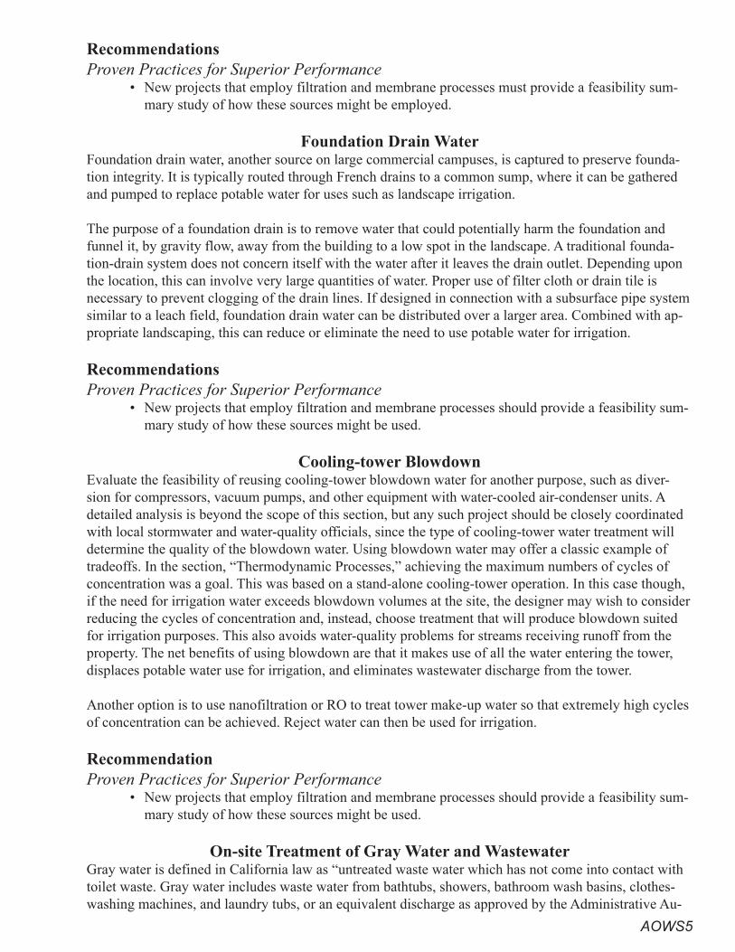
AOWS�
RecommendationsProven Practices for Superior Performance
• New projects that employ filtration and membrane processes must provide a feasibility sum-mary study of how these sources might be employed.
Foundation Drain WaterFoundation drain water, another source on large commercial campuses, is captured to preserve founda-tion integrity. It is typically routed through French drains to a common sump, where it can be gathered and pumped to replace potable water for uses such as landscape irrigation.
The purpose of a foundation drain is to remove water that could potentially harm the foundation and funnel it, by gravity flow, away from the building to a low spot in the landscape. A traditional founda-tion-drain system does not concern itself with the water after it leaves the drain outlet. Depending upon the location, this can involve very large quantities of water. Proper use of filter cloth or drain tile is necessary to prevent clogging of the drain lines. If designed in connection with a subsurface pipe system similar to a leach field, foundation drain water can be distributed over a larger area. Combined with ap-propriate landscaping, this can reduce or eliminate the need to use potable water for irrigation.
RecommendationsProven Practices for Superior Performance
• New projects that employ filtration and membrane processes should provide a feasibility sum-mary study of how these sources might be used.
Cooling-tower BlowdownEvaluate the feasibility of reusing cooling-tower blowdown water for another purpose, such as diver-sion for compressors, vacuum pumps, and other equipment with water-cooled air-condenser units. A detailed analysis is beyond the scope of this section, but any such project should be closely coordinated with local stormwater and water-quality officials, since the type of cooling-tower water treatment will determine the quality of the blowdown water. Using blowdown water may offer a classic example of tradeoffs. In the section, “Thermodynamic Processes,” achieving the maximum numbers of cycles of concentration was a goal. This was based on a stand-alone cooling-tower operation. In this case though, if the need for irrigation water exceeds blowdown volumes at the site, the designer may wish to consider reducing the cycles of concentration and, instead, choose treatment that will produce blowdown suited for irrigation purposes. This also avoids water-quality problems for streams receiving runoff from the property. The net benefits of using blowdown are that it makes use of all the water entering the tower, displaces potable water use for irrigation, and eliminates wastewater discharge from the tower.
Another option is to use nanofiltration or RO to treat tower make-up water so that extremely high cycles of concentration can be achieved. Reject water can then be used for irrigation.
RecommendationProven Practices for Superior Performance
• New projects that employ filtration and membrane processes should provide a feasibility sum-mary study of how these sources might be used.
On-site Treatment of Gray Water and WastewaterGray water is defined in California law as “untreated waste water which has not come into contact with toilet waste. Gray water includes waste water from bathtubs, showers, bathroom wash basins, clothes-washing machines, and laundry tubs, or an equivalent discharge as approved by the Administrative Au-
AOWS6
thority. It also does not include waste water from kitchen sinks, photo-lab sinks, dishwashers, or laundry water from soiled diapers,” in Title 24 section 5 of the Code. The use of gray water or on-site treatment of wastewater for on-site reuse requires a project-by-project analysis and is beyond the scope of this document. However, many commercial projects have employed technologies ranging from simply using septic tanks and near-surface dosing of the effluent for subsurface irrigation to the installation of full-ca-pacity wastewater-treatment plants, followed by conventional landscape irrigation. Another example is treating effluent to a quality sufficient for toilet and urinal flushing.
As an example, the 250-unit Solaire Apartments in Battery Park was a private-public partnership and is the first “green” residential high-rise building that incorporates advanced materials, energy conservation, and water reuse in an urban setting. The Solaire Apartments selected the ZENON Membrane Solutions proprietary ZeeWeed MBR (membrane bioreactor) process to treat, store, and reuse wastewater for toilet flushing, irrigation, and cooling towers. This approach reduces the fresh water taken from the city’s water supply by more than 75 percent and significantly decreases energy costs, since less drinking water is pumped from the city’s treatment plant and wastewater is not transferred to the city’s wastewater treat-ment system. The system is the first on-site water-recycling system in the U.S. built inside a multi-fam-ily, residential building.
Gray water from wash basins, bathing and showers, and laundry operations has also been considered.
A primary concern is to involve health-department, code-enforcement, and stormwater-quality officials in the design and development of any project to ensure that all applicable environmental concerns are taken into account, that appropriate technologies are employed, and that regulations are met.
RecommendationProven Practices for Superior Performance
• New projects that employ filtration and membrane processes should provide a feasibility sum-mary study of how these sources might be used.
Multiple SourcesPlumbing of rainwater, gray water, drain water, and blowdown from various sources to common end uses, like landscape irrigation, or non-potable indoor uses, such as toilet flushing, is not common, but is recommended. Cost effectiveness of such “hybrid” systems is improved by diversifying the sources of water and improving the consistency of water availability, since rainfall episodes, often the largest and most significant single source of water, are sometimes separated by long dry periods.
Gray water generally does not contain fecal matter and, thus, can more easily be treated and reused on-site. Gray water requires simple filtration to remove suspended particles and, when stored, requires only treatments such as chlorination for odor or aeration for nutrients in the water.
RecommendationsProven Practices for Superior Performance
• Clarify in local ordinances the specific plumbing uses of alternative sources of water and their relationships to the potable-water system.
ReferencesBrown, C., et al. 2005. The Texas Manual on Rainwater Harvesting, 3rd ed., Texas Water Develop-
ment Board.
AOWS7
California Administrative Code, Title 24, Part 5. 1997. Appendix G Graywater Systems.
GE Water & Process Technologies. ZENON Membrane Solutions. www.zenon.com/resources/case_studies/water_reuse/solaire_apartments_battery_park.shtml.
Hoffman, B. 2006. Rainwater Harvesting and Alternate Water Sources in Austin, Texas. Austin Wa-ter Utility.
Office of Water Use Efficiency, California Department of Water Resources. 200x. Recycled Water Use in the Landscape. www.owue.water.ca.gov/docs/recyluse.pdf.
U.S. Environmental Protection Agency. 2004. Effluent Guidelines – New Construction and Develop-ment. (EPA-821-R-02-007). www.epa.gov/waterscience/guide/construction/devdoc.htm.

AOWS8
This page intentionally left blank
TP1
Thermodynamic ProcessesMost commercial locations have heating and cooling systems. Many are just for air conditioning comfort of users of the building, but some can be integral to the commercial or industrial use of a facility. This section deals with types of heating and cooling systems which use water as the medium for heat transfer.
Cooling Towers• Instrumentation and metering• Cycles of concentration• Drift eliminators• Other considerations
Boilers and Water Heating • Instrumentation and metering• Cycles of concentration• Steam traps and condensate return• Nitrogen oxide and other pollution-control considerations• Other considerations
Air conditioning, refrigeration, process cooling, and dehumidification produce large quantities of “waste” heat that must be dispersed back into the environment. Heating of living- or workspace, humidification, process heating, and water heat-ing all consume large quantities of energy, as well. The interplay of energy and water can have a significant impact on the efficiency with which each of these resources is used. For perspective, consider a cooling tower as a device used to get rid of unwanted energy by evaporating water and a boiler as a way to generate energy that will ultimately be thrown away, most often in the form of unwanted hot water or steam. In all of these processes, energy conservation will reduce wa-ter use and, conversely, water conservation will reduce energy use.
For example, capturing waste heat being rejected from an air-conditioning sys-tem for use in a cooling tower to preheat boiler feed-water will reduce both fuel needed to heat the water and the load on the cooling tower. This will result in reduced make-up water requirements for the tower. In another example, the use of cogeneration, such as using a gas turbine to generate electricity and then using the waste heat from the turbine to heat water, is being practiced today. Cogeneration results in both on-site water and energy savings, since the waste energy is reused and not rejected to a cooling system. Upstream, energy and water savings can also be realized.
In this section, the two major water-using devices found in thermodynamic opera-tions, cooling towers and boilers, will be discussed, with recommendations for significant reductions in water and energy use.
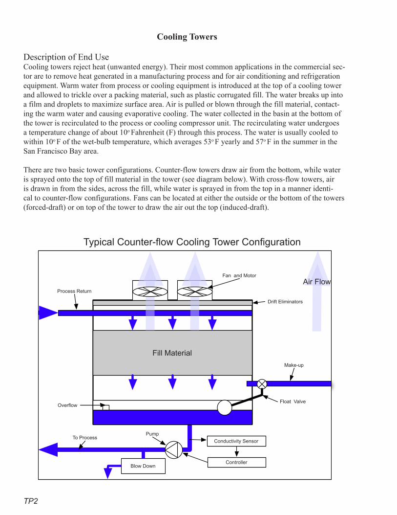
TP2
Cooling Towers
Description of End UseCooling towers reject heat (unwanted energy). Their most common applications in the commercial sec-tor are to remove heat generated in a manufacturing process and for air conditioning and refrigeration equipment. Warm water from process or cooling equipment is introduced at the top of a cooling tower and allowed to trickle over a packing material, such as plastic corrugated fill. The water breaks up into a film and droplets to maximize surface area. Air is pulled or blown through the fill material, contact-ing the warm water and causing evaporative cooling. The water collected in the basin at the bottom of the tower is recirculated to the process or cooling compressor unit. The recirculating water undergoes a temperature change of about 10o Fahrenheit (F) through this process. The water is usually cooled to within 10o F of the wet-bulb temperature, which averages 53o F yearly and 57o F in the summer in the San Francisco Bay area.
There are two basic tower configurations. Counter-flow towers draw air from the bottom, while water is sprayed onto the top of fill material in the tower (see diagram below). With cross-flow towers, air is drawn in from the sides, across the fill, while water is sprayed in from the top in a manner identi-cal to counter-flow configurations. Fans can be located at either the outside or the bottom of the towers (forced-draft) or on top of the tower to draw the air out the top (induced-draft).
Fill Material
Blow Down
Air FlowFan and Motor
Process Return
Make-up
Float Valve
Drift Eliminators
Overflow
To ProcessPump
Conductivity Sensor
Controller
Typical Counter-flow Cooling Tower Configuration
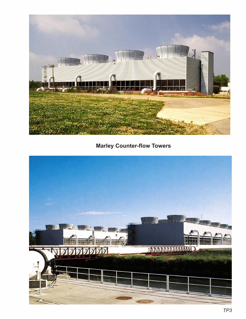
TP3
Marley Counter-flow Towers
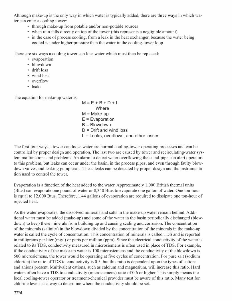
TP4
Although make-up is the only way in which water is typically added, there are three ways in which wa-ter can enter a cooling tower:
• through make-up from potable and/or non-potable sources • when rain falls directly on top of the tower (this represents a negligible amount)• in the case of process cooling, from a leak in the heat exchanger, because the water being
cooled is under higher pressure than the water in the cooling-tower loop
There are six ways a cooling tower can lose water which must then be replaced:• evaporation• blowdown• drift loss• wind loss• overflow• leaks
The equation for make-up water is: M = E + B + D + L
Where M = Make-up E = Evaporation B = Blowdown
D = Drift and wind loss L = Leaks, overflows, and other losses
The first four ways a tower can loose water are normal cooling-tower operating processes and can be controlled by proper design and operation. The last two are caused by tower and recirculating-water sys-tem malfunctions and problems. An alarm to detect water overflowing the stand-pipe can alert operators to this problem, but leaks can occur under the basin, in the process pipes, and even through faulty blow-down valves and leaking pump seals. These leaks can be detected by proper design and the instrumenta-tion used to control the tower.
Evaporation is a function of the heat added to the water. Approximately 1,000 British thermal units (Btus) can evaporate one pound of water or 8,340 Btus to evaporate one gallon of water. One ton-hour is equal to 12,000 Btus. Therefore, 1.44 gallons of evaporation are required to dissipate one ton-hour of rejected heat.
As the water evaporates, the dissolved minerals and salts in the make-up water remain behind. Addi-tional water must be added (make-up) and some of the water in the basin periodically discharged (blow-down) to keep these minerals from building up and causing scaling and corrosion. The concentration of the minerals (salinity) in the blowdown divided by the concentration of the minerals in the make-up water is called the cycle of concentration. This concentration of minerals is called TDS and is reported in milligrams per liter (mg/l) or parts per million (ppm). Since the electrical conductivity of the water is related to its TDS, conductivity measured in microsiemens is often used in place of TDS. For example, if the conductivity of the make-up water is 100 microsiemens and the conductivity of the blowdown is 500 microsiemens, the tower would be operating at five cycles of concentration. For pure salt (sodium chloride) the ratio of TDS to conductivity is 0.5, but this ratio is dependent upon the types of cations and anions present. Multivalent cations, such as calcium and magnesium, will increase this ratio. Hard waters often have a TDS to conductivity (microsiemens) ratio of 0.6 or higher. This simply means the local cooling-tower operator or treatment-chemical provider must be aware of this ratio. Many test for chloride levels as a way to determine where the conductivity should be set.
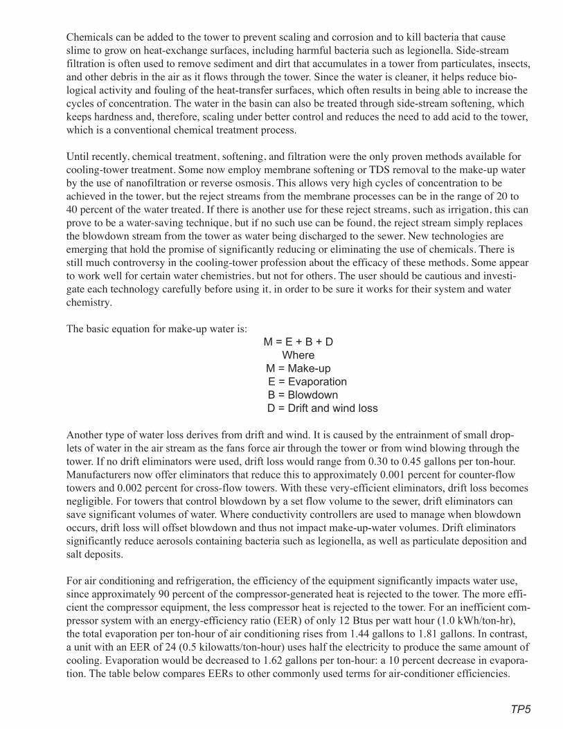
TP�
Chemicals can be added to the tower to prevent scaling and corrosion and to kill bacteria that cause slime to grow on heat-exchange surfaces, including harmful bacteria such as legionella. Side-stream filtration is often used to remove sediment and dirt that accumulates in a tower from particulates, insects, and other debris in the air as it flows through the tower. Since the water is cleaner, it helps reduce bio-logical activity and fouling of the heat-transfer surfaces, which often results in being able to increase the cycles of concentration. The water in the basin can also be treated through side-stream softening, which keeps hardness and, therefore, scaling under better control and reduces the need to add acid to the tower, which is a conventional chemical treatment process.
Until recently, chemical treatment, softening, and filtration were the only proven methods available for cooling-tower treatment. Some now employ membrane softening or TDS removal to the make-up water by the use of nanofiltration or reverse osmosis. This allows very high cycles of concentration to be achieved in the tower, but the reject streams from the membrane processes can be in the range of 20 to 40 percent of the water treated. If there is another use for these reject streams, such as irrigation, this can prove to be a water-saving technique, but if no such use can be found, the reject stream simply replaces the blowdown stream from the tower as water being discharged to the sewer. New technologies are emerging that hold the promise of significantly reducing or eliminating the use of chemicals. There is still much controversy in the cooling-tower profession about the efficacy of these methods. Some appear to work well for certain water chemistries, but not for others. The user should be cautious and investi-gate each technology carefully before using it, in order to be sure it works for their system and water chemistry.
The basic equation for make-up water is:M = E + B + D
WhereM = Make-up
E = Evaporation B = Blowdown
D = Drift and wind loss
Another type of water loss derives from drift and wind. It is caused by the entrainment of small drop-lets of water in the air stream as the fans force air through the tower or from wind blowing through the tower. If no drift eliminators were used, drift loss would range from 0.30 to 0.45 gallons per ton-hour. Manufacturers now offer eliminators that reduce this to approximately 0.001 percent for counter-flow towers and 0.002 percent for cross-flow towers. With these very-efficient eliminators, drift loss becomes negligible. For towers that control blowdown by a set flow volume to the sewer, drift eliminators can save significant volumes of water. Where conductivity controllers are used to manage when blowdown occurs, drift loss will offset blowdown and thus not impact make-up-water volumes. Drift eliminators significantly reduce aerosols containing bacteria such as legionella, as well as particulate deposition and salt deposits.
For air conditioning and refrigeration, the efficiency of the equipment significantly impacts water use, since approximately 90 percent of the compressor-generated heat is rejected to the tower. The more effi-cient the compressor equipment, the less compressor heat is rejected to the tower. For an inefficient com-pressor system with an energy-efficiency ratio (EER) of only 12 Btus per watt hour (1.0 kWh/ton-hr), the total evaporation per ton-hour of air conditioning rises from 1.44 gallons to 1.81 gallons. In contrast, a unit with an EER of 24 (0.5 kilowatts/ton-hour) uses half the electricity to produce the same amount of cooling. Evaporation would be decreased to 1.62 gallons per ton-hour: a 10 percent decrease in evapora-tion. The table below compares EERs to other commonly used terms for air-conditioner efficiencies.
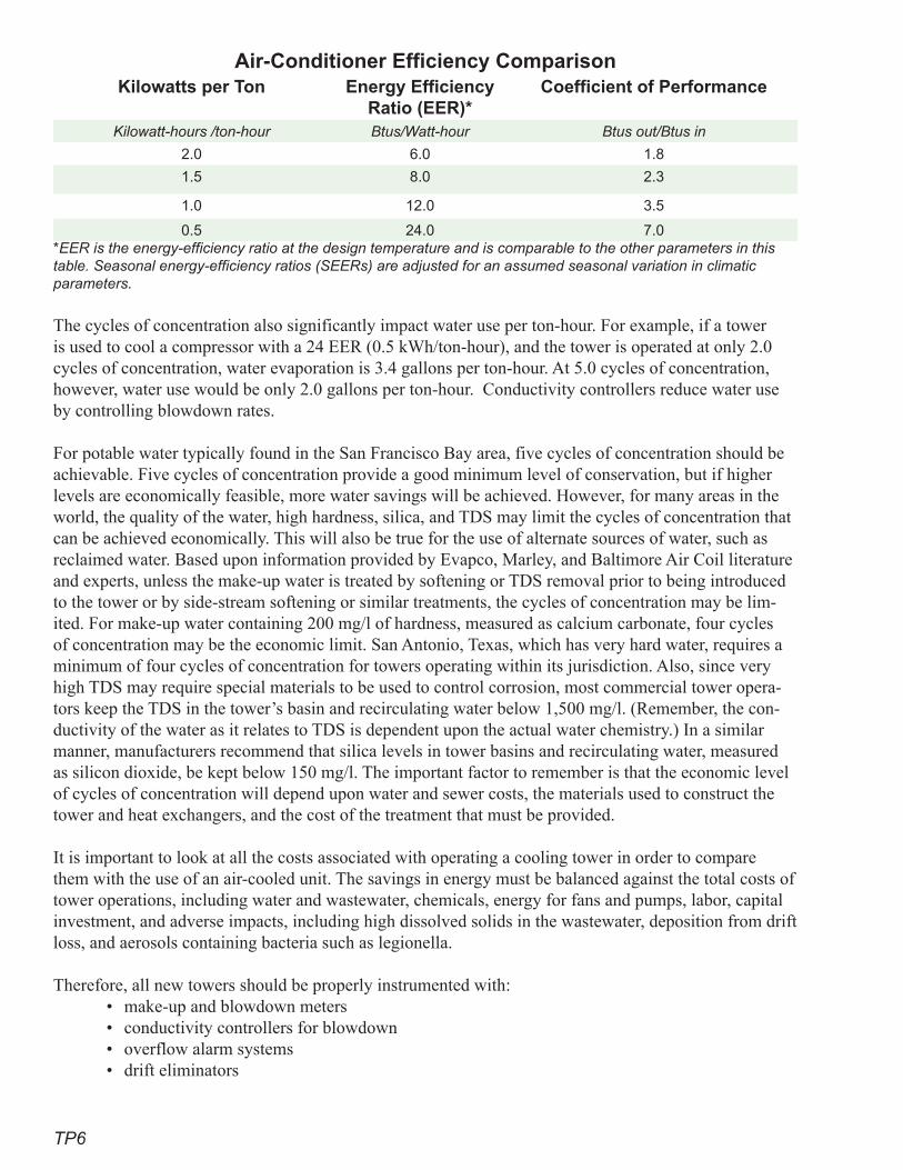
TP6
Air-Conditioner Efficiency ComparisonKilowatts per Ton Energy Efficiency
Ratio (EER)*Coefficient of Performance
Kilowatt-hours /ton-hour Btus/Watt-hour Btus out/Btus in
2.0 6.0 1.8
1.5 8.0 2.3
1.0 12.0 3.5
0.5 24.0 7.0*EER is the energy-efficiency ratio at the design temperature and is comparable to the other parameters in this table. Seasonal energy-efficiency ratios (SEERs) are adjusted for an assumed seasonal variation in climatic parameters.
The cycles of concentration also significantly impact water use per ton-hour. For example, if a tower is used to cool a compressor with a 24 EER (0.5 kWh/ton-hour), and the tower is operated at only 2.0 cycles of concentration, water evaporation is 3.4 gallons per ton-hour. At 5.0 cycles of concentration, however, water use would be only 2.0 gallons per ton-hour. Conductivity controllers reduce water use by controlling blowdown rates.
For potable water typically found in the San Francisco Bay area, five cycles of concentration should be achievable. Five cycles of concentration provide a good minimum level of conservation, but if higher levels are economically feasible, more water savings will be achieved. However, for many areas in the world, the quality of the water, high hardness, silica, and TDS may limit the cycles of concentration that can be achieved economically. This will also be true for the use of alternate sources of water, such as reclaimed water. Based upon information provided by Evapco, Marley, and Baltimore Air Coil literature and experts, unless the make-up water is treated by softening or TDS removal prior to being introduced to the tower or by side-stream softening or similar treatments, the cycles of concentration may be lim-ited. For make-up water containing 200 mg/l of hardness, measured as calcium carbonate, four cycles of concentration may be the economic limit. San Antonio, Texas, which has very hard water, requires a minimum of four cycles of concentration for towers operating within its jurisdiction. Also, since very high TDS may require special materials to be used to control corrosion, most commercial tower opera-tors keep the TDS in the tower’s basin and recirculating water below 1,500 mg/l. (Remember, the con-ductivity of the water as it relates to TDS is dependent upon the actual water chemistry.) In a similar manner, manufacturers recommend that silica levels in tower basins and recirculating water, measured as silicon dioxide, be kept below 150 mg/l. The important factor to remember is that the economic level of cycles of concentration will depend upon water and sewer costs, the materials used to construct the tower and heat exchangers, and the cost of the treatment that must be provided.
It is important to look at all the costs associated with operating a cooling tower in order to compare them with the use of an air-cooled unit. The savings in energy must be balanced against the total costs of tower operations, including water and wastewater, chemicals, energy for fans and pumps, labor, capital investment, and adverse impacts, including high dissolved solids in the wastewater, deposition from drift loss, and aerosols containing bacteria such as legionella.
Therefore, all new towers should be properly instrumented with:• make-up and blowdown meters• conductivity controllers for blowdown • overflow alarm systems• drift eliminators
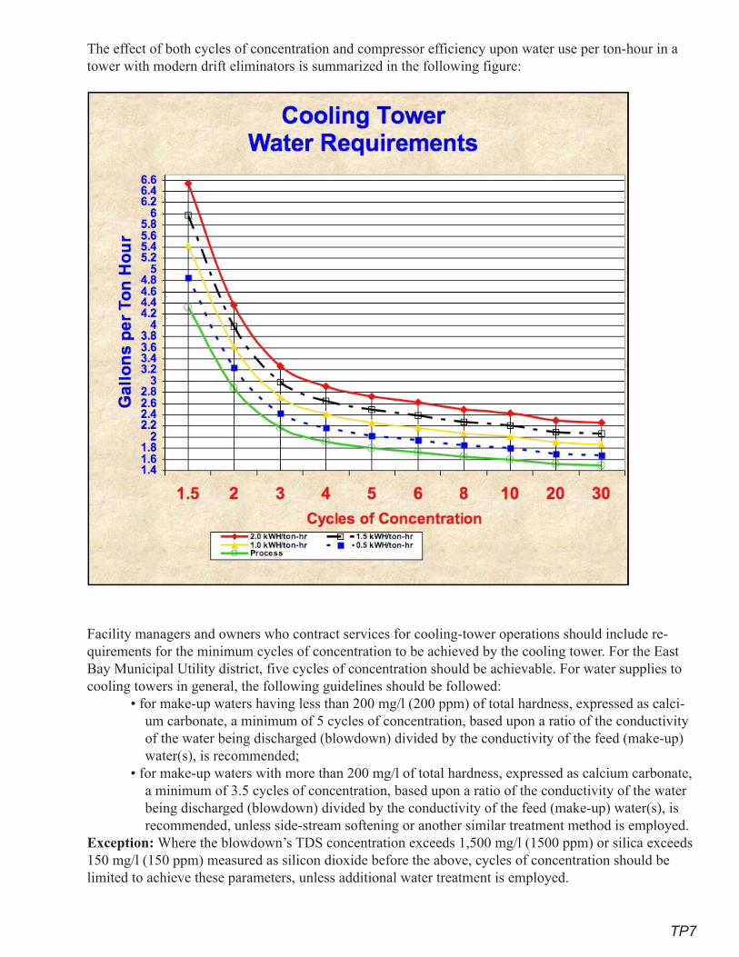
TP7
The effect of both cycles of concentration and compressor efficiency upon water use per ton-hour in a tower with modern drift eliminators is summarized in the following figure:
Facility managers and owners who contract services for cooling-tower operations should include re-quirements for the minimum cycles of concentration to be achieved by the cooling tower. For the East Bay Municipal Utility district, five cycles of concentration should be achievable. For water supplies to cooling towers in general, the following guidelines should be followed:
• for make-up waters having less than 200 mg/l (200 ppm) of total hardness, expressed as calci-um carbonate, a minimum of 5 cycles of concentration, based upon a ratio of the conductivity of the water being discharged (blowdown) divided by the conductivity of the feed (make-up) water(s), is recommended;
• for make-up waters with more than 200 mg/l of total hardness, expressed as calcium carbonate, a minimum of 3.5 cycles of concentration, based upon a ratio of the conductivity of the water being discharged (blowdown) divided by the conductivity of the feed (make-up) water(s), is recommended, unless side-stream softening or another similar treatment method is employed.
Exception: Where the blowdown’s TDS concentration exceeds 1,500 mg/l (1500 ppm) or silica exceeds 150 mg/l (150 ppm) measured as silicon dioxide before the above, cycles of concentration should be limited to achieve these parameters, unless additional water treatment is employed.

TP8
Cost-Effectiveness Analysis Tower operating-cost considerations when selecting an air or water-cooled system include the following:
• Capital cost for towers, installed, is about $100 per ton. Life expectancy is about 15 years. • Air-conditioning towers operate about 2,600 hours a year, so capital cost is about 0.25 cents
per ton-hour. Refrigeration towers operate about 3,500 hours a year at a capital cost of about .19 cents per ton-hour.
• Towers consume 2.2 gallons of water per ton-hour for a cost of about 1.5 cents per ton-hour.• Energy use is about 0.04 kWh or 0.3 cents per ton-hour.• Chemicals, operations and maintenance (O&M) of about 0.15 full-time-equivalent employees
(FTE), and other maintenance add an additional 0.5 cents per ton-hour, for a total of about 2.8 cents per ton-hour.
Savings Due to Increased Cooling-tower EfficiencyA detailed analysis of the increase in cooling-tower efficiency will depend upon local conditions. How-ever, if a tower’s cycles of concentration increase from 2.0 to 5.0, the water savings will be 1.2 gallons per ton-hour, since the 3.2 gallons needed per ton-hour at 2.0 cycles decreases to 2.0 gallons per ton-hour at 5.0 cycles. The added savings in water and wastewater alone will be 0.9 cents per ton-hour. For a 500-ton tower operating at a 30 percent annual load factor, water use at 2.0 cycles is 4.2 million gallons per year, while the same tower operating at 5.0 cycles will use only 2.6 million gallons, for a savings of 1.6 million gallons a year.
Baltimore Air Coil Cross-Flow Tower
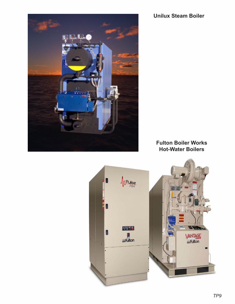
TP9
Unilux Steam Boiler
Fulton Boiler Works Hot-Water Boilers
TP10
RecommendationsProven Practices for Superior Performance
• Require a life-cycle analysis, including all operating, capital, and personnel costs, to determine whether the use of a cooling tower is more cost-effective than air cooling.
• Require all cooling towers to be equipped with conductivity controllers, make-up and blow-down meters, and overflow alarms.
• Require towers to be operated at a minimum of five cycles of concentration in the San Fran-cisco and East Bay Municipal Utility District areas for towers using potable water, depending upon the water chemistry of the make-up water used, including considerations for reclaimed water or on-site sources.
• Require all towers to have high-efficiency drift eliminators that reduce drift loss to less than 0.002 percent of circulating water volume for cross-flow towers and 0.001 percent for counter-flow towers.
• Prohibit cooling towers for single-family residential use.Additional Practices That Achieve Significant Savings
• Evaluate an entire building or process for maximum energy efficiency, since a more efficient building will reject less heat to the cooling tower.
• Evaluate the possibility of waste-heat recovery, since this heat will be put to beneficial use and will not be rejected to the tower.
• Require operator training.• Prohibit cooling towers of less than 100 tons for commercial air-conditioning systems.• Establish a utility-wide monitoring and reporting process.
ReferencesCooling towers, air-cooled heat exchangers, and industrial coolers (or heat-rejection equipment)
www.seav.sustainability.vic.gov.au/manufacturing/sustainable_manufacturing/resource.asp?action=show_resource&resourcetype=2&resourceid=28.
Hoffman, H. W. (Bill). 1994. Analyst Manual for Institutional and Commercial Water Use Surveys. Texas Water Development Board.
Holdaway, Ron, P.E. February 2004. “Water Treatment as Insurance.” Maintenance Magazine.
Parke, Steven A. Ozone Treatment for Cooling Towers. Pacific Northwest National Laboratory. Rich-land, Washington.
Boilers and Water Heating
Description of End UseThe term “boiler” is used to describe both steam boilers and water-heating systems in many commer-cial operations. Steam systems are used for process heat for hospitals, large kitchens, bakeries, and dry cleaning. Historically, steam radiators were used for building heat, but their use is limited now. The term is also used in many commercial operations to describe equipment used to heat water for processes, building heating, and hot-water supply.
Steam Boilers Steam boilers produce steam by boiling water. The temperature of the steam depends upon the level of pressure at which the boiler works. Low-pressure boilers are used for most commercial operations. High-pressure boilers are more commonly used for power generation and industrial processes. Water
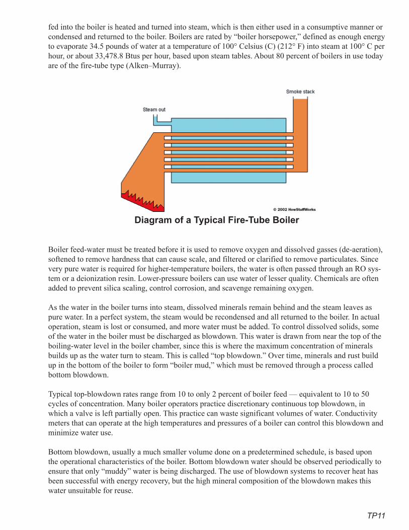
TP11
fed into the boiler is heated and turned into steam, which is then either used in a consumptive manner or condensed and returned to the boiler. Boilers are rated by “boiler horsepower,” defined as enough energy to evaporate 34.5 pounds of water at a temperature of 100° Celsius (C) (212° F) into steam at 100° C per hour, or about 33,478.8 Btus per hour, based upon steam tables. About 80 percent of boilers in use today are of the fire-tube type (Alken–Murray).
Diagram of a Typical Fire-Tube Boiler
Boiler feed-water must be treated before it is used to remove oxygen and dissolved gasses (de-aeration), softened to remove hardness that can cause scale, and filtered or clarified to remove particulates. Since very pure water is required for higher-temperature boilers, the water is often passed through an RO sys-tem or a deionization resin. Lower-pressure boilers can use water of lesser quality. Chemicals are often added to prevent silica scaling, control corrosion, and scavenge remaining oxygen.
As the water in the boiler turns into steam, dissolved minerals remain behind and the steam leaves as pure water. In a perfect system, the steam would be recondensed and all returned to the boiler. In actual operation, steam is lost or consumed, and more water must be added. To control dissolved solids, some of the water in the boiler must be discharged as blowdown. This water is drawn from near the top of the boiling-water level in the boiler chamber, since this is where the maximum concentration of minerals builds up as the water turn to steam. This is called “top blowdown.” Over time, minerals and rust build up in the bottom of the boiler to form “boiler mud,” which must be removed through a process called bottom blowdown.
Typical top-blowdown rates range from 10 to only 2 percent of boiler feed — equivalent to 10 to 50 cycles of concentration. Many boiler operators practice discretionary continuous top blowdown, in which a valve is left partially open. This practice can waste significant volumes of water. Conductivity meters that can operate at the high temperatures and pressures of a boiler can control this blowdown and minimize water use.
Bottom blowdown, usually a much smaller volume done on a predetermined schedule, is based upon the operational characteristics of the boiler. Bottom blowdown water should be observed periodically to ensure that only “muddy” water is being discharged. The use of blowdown systems to recover heat has been successful with energy recovery, but the high mineral composition of the blowdown makes this water unsuitable for reuse.
TP12
Steam does its work by recondensing to water and releasing its heat of vaporization. For efficiency and water- and energy-conservation, this condensate should be returned to the boiler, since it is pure, very-hot water. Adequately sized steam traps coupled with condensate-return pumps comprise a good system. Since condensate can pick up rust, particulates, and other contaminates, condensate polishing with filters or ion-exchange resins is sometimes practiced. According to most codes, if condensate return is not fea-sible, water must be cooled prior to discharge to a sanitary sewer. This offers additional water-conserva-tion opportunities, as will be seen with steam sterilizers in medical facilities.
Hot-Water Boilers Hot-water boilers are water-heating systems and do not involve the production of steam. The term “boiler” is used, but these are actually just large water-heaters. There are two major system configura-tions: open and recirculating. Open systems provide hot water to an end use, such as bathing, laundry, or dishwashing operations. The water is not returned to the heating system. These can either be direct-sup-
ply systems or have loop piping where the hot water is circulated with a pump back to the water heater. Open systems are usually found in food service and laundry operations.
Recirculating systems are usually found in hotels and large buildings where having hot water instanta-neously is desired. Recirculating systems are also commonly used for building heating, where hot water is supplied for space heating, using either air heat-exchange (either forced or convection) or hydronic floor-heating systems. The water in the closed loop is generally treated to help control corrosion and scaling. Additional water is needed only to make up for leaks and periodic changes of the water.
Water-Savings PotentialSteam boilers offer many unique opportunities for water savings. Conductivity controllers, the proper use of steam traps and condensate-return systems, and good energy-conservation practices can help reduce boiler feed-rates. Conductivity controllers reduce water use by controlling blowdown, while good steam traps and condensate-return systems ensure that high-quality, hot steam condensate is returned. Much depends upon the size and application of the boiler. The amount of make-up water needed de-pends upon the amount of condensate returned. The following examples illustrate how these improve-ments in water-use efficiency add up to water savings.
Examples: 1. A boiler produces 5,000 pounds of steam per hour (equal to 599.5 gallons of water at 8.34 pounds per gallon). This is equal to 5.0 million Btus per hour at 1,000 Btus per pound.
2. The conductivity controller for blowdown is set at 10 cycles. This means 10 percent of the water fed to the boiler will be discharged as blowdown. M = CL + B Where: M = Makeup CL = Condensate Loss B = BlowdownCycles of concentration also equals M/B. For 10 cycles M/B = 10.1 or blowdown = 1.0 divided by the cycles of concentration = 01.M M = CL + (0.1M)
3. Eighty (80) percent of the condensate is returned.
TP13
The boiler produces 5,000 pounds of steam, but only 80 percent is returned. The make-up to replace this is equal to 1,000 pounds, or 119.9 gallons (1,000 pounds/8.34 pounds per gallon). M = 119.9 + 0.1M 0.9M = 119.9
M = 119.9/0.9 = 133.2 gallons
If the return rate is increased to 95 percent, only 250 pounds or 30.1 gallons of condensate would be lost. If the cycles of concentration remain at 10, the make-up water would equal: M = 30.1/0.9 = 34.5 gallonsor a savings of 133.2 - 34.4 = 78.7 gallons per hour (gph).
If the cycles of concentration are also increased to 35, the make-up to blowdown ratio would be 1/35 = 0.0286. Therefore, Blowdown (B) = M × 0.0286 M = 30.1 gallons + 0.0286M M = 30.1/(1.0.0286) = 30.1/0.9714 = 31.0 gallons.
This is equal to a savings of 133.2 gallons - 31.0 gallons = 102.2 gallons or 77 percent.
Hot-water boilers produce hot water for all types of uses, ranging from domestic use to building heat-ing with hydronic and convective systems. Each use presents different opportunities for saving water, depending upon the operation of system. The two major water-saving actions related to hot-water boilers are good end-use water conservation and preventing leaks in the distribution system.
RecommendationsProven Practices for Superior PerformanceSteam Boilers
• Require steam boilers of 200 boiler horsepower (BHP) or greater to be equipped with conduc-tivity controllers to regulate top blowdown.
• Require steam boilers of 200 BHP or greater to have condensate-return meters.• Require steam-boiler distribution lines and equipment to be equipped with steam traps meeting
all codes.• Require all steam boilers to have make-up meters on the feedwater lines.• The cycles of concentration at which a boiler operates is dependent upon water chemistry,
boiler operating pressure, temperature, and related factors. Maximizing the cycles of concen-tration will reduce water use.
Hot-Water Boilers • Require make-up meters on all cold-water feed lines to boilers (water heaters) of more than
100,000 Btus per hour. • Require make-up meters on lines feeding closed-loop hot-water systems for heating.
Additional Practices that Achieve Significant SavingsSteam Boilers
• Equip all steam boilers with conductivity controllers.• Operate all steam boilers at twenty cycles of concentration or greater (5 percent or less of
make-up water).Hot-Water Boilers
• Have boiler (water-heater) temperature and make-up meters clearly visible to the operator.
TP14
Cost-Effectiveness Analysis Example for Steam-Boiler Conductivity Controllers (taken directly from the Pacific Northwest Pollution Prevention Resource Center, 20057).
Assumptions:• Automatic conductivity blowdown-control system reduces the blowdown rate from 8 to 6
percent.• Natural-gas-fired steam boiler operates continuously at 150-psig (pounds per square inch
gauge), 100,000 pounds-per-hour.• Make-up water temperature of 60° F.• Boiler efficiency of 82 percent.• No heat exchanger for recovery of heat from blowdown water.
Boiler Feedwater Savings• Before installing control system:
100,000 pounds per hour / (1-0.08)=108,695 pounds per hour.• After installing control system:
100,000 pounds per hour / (1-0.06)=106,383 pounds per hour.• Water Saved: 108,695 – 106,383 = 2,312 pounds per hour. • At 8,760 operating hours per year, the savings is 20.3 million pounds or 2.4 million gallons per
year.
Example for Hot-Water BoilerHot-water boilers do not have a blowdown or discharge. These are very large water-heaters. Savings are achieved by reducing hot-water use. The value of the hot water saved includes the energy needed to heat the water and the cost of the water and wastewater.
ReferencesAlken-Murray Corporation. Why Treat the Water in Your Boiler? New Hyde Park, New York. www.
alken-murray.com/Boilerworks.htm.
Chana, Vinita; White, Stewart; Howe, Carol; and Meenakshe, Jha. Sustainable Water Management in Commercial Office Buildings. Institute for Sustainable Futures. www.isf.uts.edu.au/publications/chanan.html.
Clayton Industries (17477 Hurley Street, City of Industry, CA 91744-5106). Web site on boilers. www.claytonindustries.com.
Cohen, Ronnie; Nelson, Barry; and Wolff, Gary. August 2004. Energy Down the Drain – The Hidden Cost of California’s Water Supply. Pacific Institute.
Encyclopedia of Alternative Energy & Sustainable Living. www.daviddarling.info/encyclopedia/B/AE_boiler_horsepower.html.
Hoffman, H. W. (Bill). 1994. Analyst Manual for Institutional and Commercial Water Use Surveys. Texas Water Development Board.
Hoffman, H. W. (Bill). March 2006. Building Reduced Water and Wastewater Cost into the Design. Austin Water Utility. Austin, Texas.
»
»

TP1�
Hoffman, H. W. (Bill), and Sutton, John T. 2003. State Energy Conservation Office Suggested Water Efficiency Guidelines for Buildings and Equipment at State Facilities. Texas State Energy Con-servation Office.
New Mexico. Office of State Engineer. July 1999. A Water Conservation Guide for Commercial, Institutional and Industrial Water Users.
Pacific Northwest Pollution Prevention Research Center. February 2005. Pollution Prevention Tech-nology Profile: Conductivity Controls in Water Rinsing, Cooling Towers, and Boilers. Seattle, Washington.
Pollution Prevention International. March 2004. Commercial, Institutional, and Industrial Water Use Survey Program Final Report. For Santa Clara Valley Water District.
U.S. Department of Energy. EERE. Install an Automatic Blowdown Control Program. Industrial Technology Program Tip Sheet 23.
U.S. Department of Energy. Office of Industrial Technologies. 2002. Improving Steam System Perfor-mance. www.p2pays.org/ref/21/20921.htm FEMP BMP 6.

TP16
This page intentionally left blank
FSO1
Food-Service OperationsMost locations where large numbers of people assemble have food-service facili-ties. Restaurants and pastry/doughnut shops are obvious members of this category. Most schools, hospitals, hotels, service stations with stores, and convenience stores have food-service operations. Larger office buildings, factories, and insti-tutional facilities provide food service of some type to their employees. Because food-service facilities are characterized by many kinds of water uses and high en-ergy and water consumption, they are prime targets for incentives or requirements for water-efficient equipment, both for new construction and for retrofit of exist-ing facilities. This report focuses on efficient equipment that should be required or at least considered for new construction.
Water-using technologies that have specific potential for water conservation include:
Refrigeration Equipment• Refrigerators and freezers• Ice-making machines
Cooking and Food-Service Equipment• Steam tables• Steam kettles• Pasta cookers• Steamers• Combination ovens (a new product in development) • Dipper wells• Woks
Scullery Operations• Garbage disposers• Pre-rinse spray valves• Dishwashers
Washing and Sanitation • Floor washing• Hood washing
Refrigeration Equipment
Refrigerators and Freezers Refrigeration includes both coolers and freezers used to preserve food. Three ma-jor considerations for minimizing water use in refrigeration operations are:

FSO2
• having adequate refrigeration equipment to minimize the need for thawing food under flowing water
• eliminating once-through cooling• encouraging air-cooling, especially with remote (outside) compressors that exhaust waste heat
outside the building
Description of End UsePotential water savings from refrigeration equipment fall into three categories:
• sizing refrigerators to provide adequate capacity for thawing frozen food. The California Uni-form Retail Food Facilities Law requires that food be defrosted in a refrigerator or be thawed under constantly flowing water that remains below 75o F. Thawing under flowing water is always wasteful and should be avoided whenever possible by designing for adequate refrigera-tion equipment to be installed in food-service facilities.
• eliminating once-through or pass-though water-cooling by installing air-cooled equipment. Reach-in refrigeration equipment (smaller display cases, glass- and solid-door coolers, etc.) is almost exclusively air-cooled, but large walk-in units and large display cases can be either air- or water-cooled. Some facilities use recirculating cooling water from either a chilled-water loop or a cooling tower. Although more efficient than once-through cooling, it is usually less economical than air-cooling.
• air-cooling, especially with remote (outside) compressors that exhaust waste heat outside the building, not into the working space. Energy use for air-cooled equipment is primarily a func-tion of the size and capacity of the refrigerator or freezer, combined with the energy efficiency of the equipment.
Water-Savings PotentialWater savings from installing adequate refrigeration varies greatly. Some restaurants can use thousands of gallons a day thawing food under running water in a sink. The typical kitchen faucet turned on half way has a flow rate of about 3.0 gpm and may be left on for an hour or more a day for thawing. Using equipment with once-through cooling saves approximately 145 gallons per ton hour. A three-ton refrig-erator uses 5,000 gallons of water a day for once-through cooling.
Cost-Effectiveness Analysis Example: Thawing under water in a sink versus extra refrigeration space.
• Equipment capital costs: $27 per cubic foot.• Estimated equipment life: 8 years (Nadel, 2002).• Water and energy savings: Compare the cost of water and wastewater used to thaw in a sink
with the cost of purchasing and maintaining extra refrigeration space. Three faucets flowing at 3.0 gpm, used one hour each day, consume 200,000 gallons a year. The combined water and sewer cost savings equals $1,400 a year.
• Incremental cost per AF of efficient equipment: The average operating cost of refrigeration is approximately $7.50 per cubic foot (for solid doors, Energy Star). The PV of the operating savings and amortized capital costs justify purchasing an additional 121 cubic feet of refrigera-tion. This change would save 0.6 AF of water per year at no additional cost.
Example: Once-through water-cooled vs. air-cooled.• Equipment capital costs: The incremental cost for a water-cooled unit versus a remote-head
unit is $2,000 for even the largest units.• Estimated equipment life: 10 years (Energy Star).
FSO3
• Water and energy savings: An air-cooled unit uses 145 gallons of water per ton-hour, at a cost of $1.00 per ton-hour. A water-cooled three-ton refrigeration unit working 4,000 hours a year would use 1.74 million gallons a year (5.4 AF), for an annual water and wastewater cost of $12,400. The additional energy cost for an air-cooled unit would be $300 a year.
• Incremental cost per AF of efficient equipment: The simple payback for the additional capital costs of a remote-head unit would be two months. The positive benefit per AF is $1,900.
RecommendationsProven Practices for Superior Performance
• Provide adequate refrigerator space for thawing food.• Choose energy-efficient equipment.• Prohibit once-through cooling with potable water.
Additional Practices That Achieve Significant Savings• Choose air-cooling rather than recirculating cooling-water systems.• Follow requirements in the cooling tower section of this report.
Ice-Making Machines
Description of End UseIce makers are an extension of the refrigeration-equipment category, but unique in many ways. As with refrigeration, both water-cooled and air-cooled equipment are available, with air-cooled being much more water-efficient. There are two basic types of commercial ice equipment: flake-ice and cube-ice machines. Ice-making machines are rated by the hundreds of pounds of ice the machine can make per day. One hundred pounds of ice is equal to 12 gallons of water, but actual water use depends upon the efficiency of the particular machine. Many local utilities in California provide rebates for efficient ice machines.
Flake-ice machines, including the new nugget machines, are the most energy- and water-efficient equip-ment available. Nugget machines press flake ice into a small cylindrical shape. Flake ice is crunchy and tends to melt quickly in drinks; it is often used to ice down food in serving lines. Nugget ice melts more slowly, can be used in most drink applications, and is increasingly being used instead of cube ice. Nug-get ice is appealing in soda-fountain drinks, since the whole nugget becomes flavored with the soda and is easy to chew.
Cube-ice machines produce clear cubes of ice by washing the cubes as they freeze, so any minerals that may precipitate on the forming cubes are washed away. Cube-ice machines are the most common com-mercial ice-making equipment.
According to the Consortium for Energy Efficiency (CEE), hospitals account for 39.4 percent of all commercial ice-maker purchases, followed by hotels (22.3 percent), restaurants (13.8 percent), retail outlets (8.5 percent), schools (8.5 percent), offices (4.3 percent), and grocery stores (3.2 percent).
Water-Savings Potential Flake/nugget machines purge the cylindrical tubes with water two or three times a day to flush out any precipitated minerals, using 10 to 30 gallons each time. It takes 20 gallons of water to make 100 pounds of flake/nugget ice. Cube machines use water to wash the cubes so they are crystal clear, increasing wa-ter use to 30 or more gallons per 100 pounds of ice in some cases. Water-cooled units use from 72 to 240 gallons of water for every hundred pounds (12 gallons) of ice produced. Once-through systems simply dump this water into the sanitary sewer.
FSO4
The USEPA’s Energy Star program has published standards for cube-making ice machine equipment. These standards do not yet include flake and nugget machines. Once separate flake and nugget ice ma-chine standards are developed, they should be followed also. In the interim, the Food Service Technol-ogy Center has published a list of qualifying ice machines that include both cube-making and flake and nugget ice machines. When cube-making ice machines are installed, the installer will set the purge rate, the rate at which wa-ter flows over the ice plate surface to remove precipitating minerals. Having the installer set this rate to the lowest level possible will also save water.
Cost-Effectiveness Analysis Example: 700-pound air-cooled vs. water-cooled ice machines:
• Equipment capital costs: $1,000 additional for an air-cooled unit.• Estimated equipment life: 7 years, depending on usage.• Water and energy savings: An air-cooled machine producing 700 pounds of ice per day will
save 1,350 gallons per day versus a water-cooled machine. The net annual operating cost sav-ings is $1,600 to $2,300 for an air-cooled versus a water-cooled machine, depending upon the air-cooled configuration. Simple payback for selecting an air-cooled machine is 12 months.
• Incremental cost per AF of efficient equipment: The savings is 10.2 to 10.7 AF over the life of the machine. The net PV of the operating savings is $12,100 for an air-cooled unit in air-con-ditioned space and $9,200 for a remote-head. The positive benefit ranges from $880 to $1,180 per AF.
Example: 700-pound nugget/flake-ice versus a cube-ice machine:• Equipment capital costs: Flake- and nugget-ice machines cost from $500 to $1,200 more, de-
pending upon size, due to the cost of a mechanical auger, which removes the flakes of ice from the tubes surrounded by liquid refrigerant.
• Estimated equipment life: 6 years.• Water and energy savings: Compared with cube machines, air-cooled flake-ice machines re-
duce water use by about 15 gallons and electricity use by a kilowatt hour for every 100 pounds of ice made. An air-cooled flake machine that makes 700 pounds of ice daily will use 105 gallons and 7.0 kilowatt hours (kWh) a day fewer than a cube machine. In a year, this equals 38,000 gallons and 2,555 kilowatt hours, resulting in an annual operating savings of $475 per year. The simple payback is five months.
• Incremental cost per AF of efficient equipment: The savings will be 0.7 AF over the life of the equipment. There is a positive PV benefit of $1,800 per AF.
RecommendationsProven Practices for Superior Performance
• Prohibit once-through water-cooled ice makers.• Cube-ice machines must meet USEPA Energy Star standards for cube-ice machines. Consider
requiring Tier 3 (CEE Commercial Kitchens). • Nugget- and flake-making ice machines should be selected from the Food Service Technology
Center list of qualifying ice machines.Additional Practices That Achieve Significant Savings
• Ensure that installers set the amount of purge water to the lowest level possible for the quality of water being used.
FSO�
• Choose energy-efficient flake or nugget machines rather than cube machines. Nugget machines should be adequate for most restaurant and food-service operations, as well as for drinks in convenience stores.
• Mount compressor units outside so rejected heat is not dumped into work or living spaces. “Remote-head” is the term used to describe these outside units.
• Prefer air-cooled units to those using a cooling-tower loop, which increases water use by evaporating 7 to 9 gallons of water per 100 pounds of ice made.
Cooking and Food-Service Equipment
Steam TablesDescription of End UseSteam tables, used to keep food hot while serving, are filled with water and heated to keep the food at 140o F or higher (California Uniform Retail Service Law). At the end of the day, they are drained. The major consideration regarding water efficiency is whether a steam table is actually needed. Though in-dispensable in large cafeterias and many institutional settings, they are not needed in every food-service operation. Some tables have both wet and dry options, and others use direct-heating equipment, such as electrically heated serving wells, which use no water at all.
Water-Savings Potential Steam tables require 20 to 100 gallons of water or more per day, depending upon their design and size.
Cost-Effectiveness Analysis Steam table prices range from a few hundred to $4,000, depending upon size and capacity. The decision, in terms of water use, is whether a steam table is needed.
RecommendationsProven Practices for Superior Performance
• NoneAdditional Practices That Achieve Significant Savings
• For smaller applications, choose dry heating tables that use no water.• Prefer non-water-using equipment to steam tables, if feasible.• Use hot water from the steam table for end-of-day mopping.
Steam Kettles
Description of End UseSteam kettles are often selected for use in large facilities because, as with steam tables, temperatures can be more easily controlled, thereby preventing scorching the food. They should be installed only where large-volume food preparation justifies this water and energy use. Some steam kettles have their own heat source, but where a central boiler is used to supply the steam, the condensate should be returned to the boiler for reuse. Stand-alone steam kettles, which can use either electricity or gas as a heat source and do not require a separate boiler, are the most common type found in restaurants. Large steam kettles are more commonly found in institutional settings.
Water-Savings PotentialThe major water-savings potential for steam kettles is for the condensate to be retained and returned to the boiler, if such a system is used.
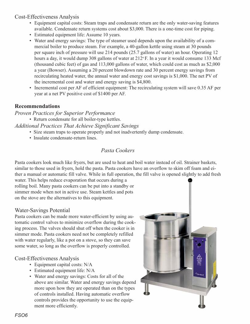
FSO6
Cost-Effectiveness Analysis • Equipment capital costs: Steam traps and condensate return are the only water-saving features
available. Condensate return systems cost about $3,000. There is a one-time cost for piping. • Estimated equipment life: Assume 10 years.• Water and energy savings: The type of steamer used depends upon the availability of a com-
mercial boiler to produce steam. For example, a 40-gallon kettle using steam at 30 pounds per square inch of pressure will use 214 pounds (25.7 gallons of water) an hour. Operating 12 hours a day, it would dump 308 gallons of water at 212o F. In a year it would consume 133 Mcf (thousand cubic feet) of gas and 113,000 gallons of water, which could cost as much as $2,000 a year (Bowser). Assuming a 20 percent blowdown rate and 30 percent energy savings from recirculating heated water, the annual water and energy cost savings is $1,000. The net PV of the incremental cost and water and energy saving is $4,800.
• Incremental cost per AF of efficient equipment: The recirculating system will save 0.35 AF per year at a net PV positive cost of $1400 per AF.
RecommendationsProven Practices for Superior Performance
• Return condensate for all boiler-type kettles.Additional Practices That Achieve Significant Savings
• Size steam traps to operate properly and not inadvertently dump condensate.• Insulate condensate-return lines.
Pasta Cookers
Pasta cookers look much like fryers, but are used to heat and boil water instead of oil. Strainer baskets, similar to those used in fryers, hold the pasta. Pasta cookers have an overflow to skim off foam and ei-ther a manual or automatic fill valve. While in full operation, the fill valve is opened slightly to add fresh water. This helps reduce evaporation that occurs during a rolling boil. Many pasta cookers can be put into a standby or simmer mode when not in active use. Steam kettles and pots on the stove are the alternatives to this equipment.
Water-Savings PotentialPasta cookers can be made more water-efficient by using au-tomatic control valves to minimize overflow during the cook-ing process. The valves should shut off when the cooker is in simmer mode. Pasta cookers need not be completely refilled with water regularly, like a pot on a stove, so they can save some water, so long as the overflow is properly controlled.
Cost-Effectiveness Analysis • Equipment capital costs: N/A• Estimated equipment life: N/A• Water and energy savings: Costs for all of the
above are similar. Water and energy savings depend more upon how they are operated than on the types of controls installed. Having automatic overflow controls provides the opportunity to use the equip-ment more efficiently.
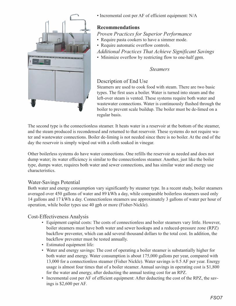
FSO7
• Incremental cost per AF of efficient equipment: N/A
RecommendationsProven Practices for Superior Performance• Require pasta cookers to have a simmer mode.• Require automatic overflow controls.Additional Practices That Achieve Significant Savings• Minimize overflow by restricting flow to one-half gpm.
Steamers
Description of End UseSteamers are used to cook food with steam. There are two basic types. The first uses a boiler. Water is turned into steam and the left-over steam is vented. These systems require both water and wastewater connections. Water is continuously flushed through the boiler to prevent scale buildup. The boiler must be de-limed on a regular basis.
The second type is the connectionless steamer. It heats water in a reservoir at the bottom of the steamer, and the steam produced is recondensed and returned to that reservoir. These systems do not require wa-ter and wastewater connections. Boiler de-liming is not needed since there is no boiler. At the end of the day the reservoir is simply wiped out with a cloth soaked in vinegar.
Other boilerless systems do have water connections. One refills the reservoir as needed and does not dump water; its water efficiency is similar to the connectionless steamer. Another, just like the boiler type, dumps water, requires both water and sewer connections, and has similar water and energy use characteristics.
Water-Savings PotentialBoth water and energy consumption vary significantly by steamer type. In a recent study, boiler steamers averaged over 450 gallons of water and 89 kWh a day, while comparable boilerless steamers used only 14 gallons and 17 kWh a day. Connectionless steamers use approximately 3 gallons of water per hour of operation, while boiler types use 40 gph or more (Fisher-Nickle).
Cost-Effectiveness Analysis • Equipment capital costs: The costs of connectionless and boiler steamers vary little. However,
boiler steamers must have both water and sewer hookups and a reduced-pressure zone (RPZ) backflow preventer, which can add several thousand dollars to the total cost. In addition, the backflow preventer must be tested annually.
• Estimated equipment life: • Water and energy savings: The cost of operating a boiler steamer is substantially higher for
both water and energy. Water consumption is about 175,000 gallons per year, compared with 13,000 for a connectionless steamer (Fisher Nickle). Water savings is 0.5 AF per year. Energy usage is almost four times that of a boiler steamer. Annual savings in operating cost is $1,800 for the water and energy, after deducting the annual testing cost for an RPZ.
• Incremental cost per AF of efficient equipment: After deducting the cost of the RPZ, the sav-ings is $2,600 per AF.
FSO8
Recommendations Proven Practices for Superior Performance
• All steamers must be either connectionless or boilerless and consume no more than three gph.
Combination Ovens
Description of End UseCombination ovens help keep food from drying out while baking or roasting. Both gas and electric mod-els are available in several configurations. One has a boiler that produces steam which is injected into the oven chamber. Others achieve high humidity with sprays, and some models have closed systems that recondense steam to achieve higher energy and water savings (Alto–Shaam). The cooking capacity of a typical oven is significant. One six-pan model can cook as many as 32 chickens at a time (Sorensen).
Water-Savings PotentialA heavily used ten-pan boiler combination oven can consume 30 to 40 gallons of water per hour, while a boilerless misting oven uses only 10 to 15, resulting in an annual savings greater than 110,000 gallons (Reed).
Gas and electric combination ovens vary widely in energy efficiency. Some models are 40 to 60 percent more energy efficient than their conventional counterparts. Inefficient models consume 360 to 480 gpd, while efficient models use only 120 to 180 gpd.
Cost-Effectiveness Analysis • Equipment capital costs: Combination ovens are expensive; small units start in the $10,000
range, while larger units can cost as much as $50,000. Energy Star examples show prices for larger, more-efficient equipment to be approximately $8,400 higher than for conventional models.
• Estimated equipment life: 10 years.• Water and energy savings: The energy savings is 12,450 kWh per year in this example. Com-
bine this with an estimated savings of 130,000 gallons of water per year, and the annual oper-ating savings is $1,700. Over the life of the equipment, this saves $17,000 in energy costs and 4 AF of water (Energy Star).
• Incremental cost per AF of efficient equipment: When both energy and water savings are con-sidered, the net benefit to the customer is $1,360 per AF or a total of $5,500.
RecommendationsProven Practices for Superior Performance
• Combination ovens must use no more than 15 gph.Additional Practices That Achieve Significant Savings
• All combination ovens should comply with the rebate list prepared by Fisher Nickel for energy rebates in California (www.fishnick.com/saveenergy/rebates/combis/combis.pdf).
Dipper Wells Dipper wells are used for applications such as rinsing ice-cream scoops on the serving line. Most have a single faucet or spigot and can be supplied with either hot or cold water.
FSO9
Water-Savings PotentialThe faucet or valve can be adjusted by the server. Typical flow rates are 0.5 to 1.0 gpm. For smaller dipper wells, a flow rate of 0.25 gpm should be adequate. In-line flow restrictors can be installed on the supply line to the dipper well. These can be set at the minimum adequate flow and locked so that em-ployees cannot increase flow.
Cost-Effectiveness Analysis• Equipment capital costs: N/A• Estimated equipment life: N/A• Water and energy savings: As many as several hundred gpd.• Incremental cost per AF of efficient equipment: N/A
Recommendations Proven Practices for Superior Performance
• In-line restrictors that reduce flow to under 0.3 gpm.
Woks
Wok stoves commonly used in oriental restaurants rely on a constant flow of water over the surface of the stove to keep it cool for the comfort of the cook. Efforts are underway in Australia to develop a “waterless wok” which employs better insulation and air cooling. For new construction, the waterless wok should be used as soon as it becomes available (Sydney, 2005). As of 2007, waterless woks can be ordered from Australia, but most American kitchen appliance dealers were unaware of them when called in a November 2007 survey.
Cost-Effectiveness Analysis • Equipment capital costs: N/A• Estimated equipment life: N/A• Water and energy savings: N/A• Incremental cost per AF of efficient equipment: N/A
Scullery Operations
Garbage DisposersThe process of scraping dishes and disposing of waste prior to dishwashing can use from zero to very large quantities of water and energy, depending upon the design of the equipment selected. Commonly found equipment includes garbage disposers, sluice troughs, and pulpers.
Garbage disposers grind food and other items that enter the grinder and send them down the sewer. This waste material adds to the solids and grease entering the sewer and the grease trap. If a grinder is used, it should be equipped with a solenoid to shut off the flow of water when not needed.
Sluice troughs are usually built into the stainless-steel table systems. Water flows continuously into the top end of the trough at 5 to 15 gpm and flushes food waste from pots, pans, dishes, etc. into a garbage disposer. Large flows of water are required. A variation of this is the recirculating system that passes the waste through a grinder, strains out the solids for flushing down the drain, and returns the water to the sluice trough to flush down more waste. These systems use only two to three gallons of make-up water a minute, but are expensive.
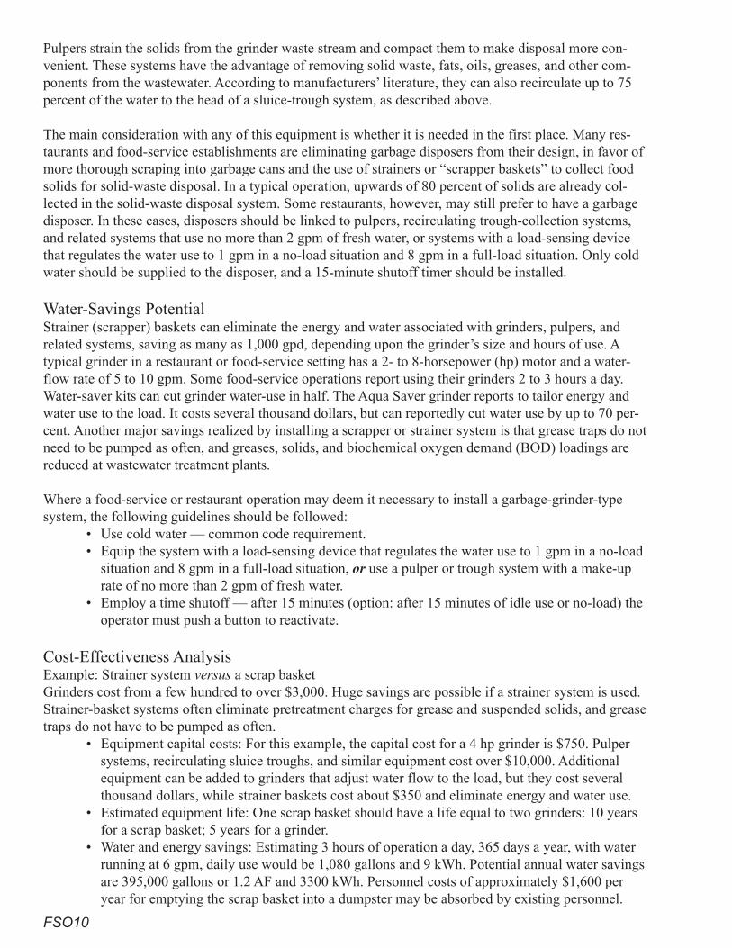
FSO10
Pulpers strain the solids from the grinder waste stream and compact them to make disposal more con-venient. These systems have the advantage of removing solid waste, fats, oils, greases, and other com-ponents from the wastewater. According to manufacturers’ literature, they can also recirculate up to 75 percent of the water to the head of a sluice-trough system, as described above.
The main consideration with any of this equipment is whether it is needed in the first place. Many res-taurants and food-service establishments are eliminating garbage disposers from their design, in favor of more thorough scraping into garbage cans and the use of strainers or “scrapper baskets” to collect food solids for solid-waste disposal. In a typical operation, upwards of 80 percent of solids are already col-lected in the solid-waste disposal system. Some restaurants, however, may still prefer to have a garbage disposer. In these cases, disposers should be linked to pulpers, recirculating trough-collection systems, and related systems that use no more than 2 gpm of fresh water, or systems with a load-sensing device that regulates the water use to 1 gpm in a no-load situation and 8 gpm in a full-load situation. Only cold water should be supplied to the disposer, and a 15-minute shutoff timer should be installed.
Water-Savings PotentialStrainer (scrapper) baskets can eliminate the energy and water associated with grinders, pulpers, and related systems, saving as many as 1,000 gpd, depending upon the grinder’s size and hours of use. A typical grinder in a restaurant or food-service setting has a 2- to 8-horsepower (hp) motor and a water-flow rate of 5 to 10 gpm. Some food-service operations report using their grinders 2 to 3 hours a day. Water-saver kits can cut grinder water-use in half. The Aqua Saver grinder reports to tailor energy and water use to the load. It costs several thousand dollars, but can reportedly cut water use by up to 70 per-cent. Another major savings realized by installing a scrapper or strainer system is that grease traps do not need to be pumped as often, and greases, solids, and biochemical oxygen demand (BOD) loadings are reduced at wastewater treatment plants.
Where a food-service or restaurant operation may deem it necessary to install a garbage-grinder-type system, the following guidelines should be followed:
• Use cold water — common code requirement.• Equip the system with a load-sensing device that regulates the water use to 1 gpm in a no-load
situation and 8 gpm in a full-load situation, or use a pulper or trough system with a make-up rate of no more than 2 gpm of fresh water.
• Employ a time shutoff — after 15 minutes (option: after 15 minutes of idle use or no-load) the operator must push a button to reactivate.
Cost-Effectiveness Analysis Example: Strainer system versus a scrap basketGrinders cost from a few hundred to over $3,000. Huge savings are possible if a strainer system is used. Strainer-basket systems often eliminate pretreatment charges for grease and suspended solids, and grease traps do not have to be pumped as often.
• Equipment capital costs: For this example, the capital cost for a 4 hp grinder is $750. Pulper systems, recirculating sluice troughs, and similar equipment cost over $10,000. Additional equipment can be added to grinders that adjust water flow to the load, but they cost several thousand dollars, while strainer baskets cost about $350 and eliminate energy and water use.
• Estimated equipment life: One scrap basket should have a life equal to two grinders: 10 years for a scrap basket; 5 years for a grinder.
• Water and energy savings: Estimating 3 hours of operation a day, 365 days a year, with water running at 6 gpm, daily use would be 1,080 gallons and 9 kWh. Potential annual water savings are 395,000 gallons or 1.2 AF and 3300 kWh. Personnel costs of approximately $1,600 per year for emptying the scrap basket into a dumpster may be absorbed by existing personnel.
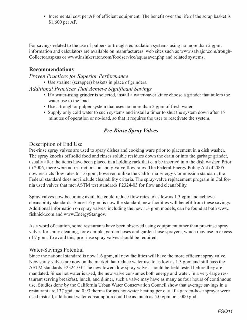
FSO11
• Incremental cost per AF of efficient equipment: The benefit over the life of the scrap basket is $1,600 per AF.
For savings related to the use of pulpers or trough-recirculation systems using no more than 2 gpm, information and calculators are available on manufacturers’ web sites such as www.salvajor.com/trough-Collector.aspxas or www.insinkerator.com/foodservice/aquasaver.php and related systems.
Recommendations Proven Practices for Superior Performance
• Use strainer (scrapper) baskets in place of grinders.Additional Practices That Achieve Significant Savings
• If a water-using grinder is selected, install a water-saver kit or choose a grinder that tailors the water use to the load.
• Use a trough or pulper system that uses no more than 2 gpm of fresh water. • Supply only cold water to such systems and install a timer to shut the system down after 15
minutes of operation or no-load, so that it requires the user to reactivate the system.
Pre-Rinse Spray Valves
Description of End UsePre-rinse spray valves are used to spray dishes and cooking ware prior to placement in a dish washer. The spray knocks off solid food and rinses soluble residues down the drain or into the garbage grinder, usually after the items have been placed in a holding rack that can be inserted into the dish washer. Prior to 2006, there were no restrictions on spray-valve flow rates. The Federal Energy Policy Act of 2005 now restricts flow rates to 1.6 gpm, however, unlike the California Energy Commission standard, the Federal standard does not include cleanability criteria. The spray-valve replacement program in Califor-nia used valves that met ASTM test standards F2324-03 for flow and cleanability.
Spray valves now becoming available could reduce flow rates to as low as 1.3 gpm and achieve cleanability standards. Since 1.6 gpm is now the standard, new facilities will benefit from these savings. Additional information on spray valves, including the new 1.3 gpm models, can be found at both www.fishnick.com and www.EnergyStar.gov.
As a word of caution, some restaurants have been observed using equipment other than pre-rinse spray valves for spray cleaning, for example, garden hoses and garden-hose sprayers, which may use in excess of 7 gpm. To avoid this, pre-rinse spray valves should be required.
Water-Savings Potential Since the national standard is now 1.6 gpm, all new facilities will have the more efficient spray valve. New spray valves are now on the market that reduce water use to as low as 1.3 gpm and still pass the ASTM standards F2324-03. The new lower-flow spray valves should be field tested before they are mandated. Since hot water is used, the new valve consumes both energy and water. In a very-large res-taurant serving breakfast, lunch, and dinner, such a valve may have as many as four hours of continuous use. Studies done by the California Urban Water Conservation Council show that average savings in a restaurant are 137 gpd and 0.93 therms for gas hot-water heating per day. If a garden-hose sprayer were used instead, additional water consumption could be as much as 5.0 gpm or 1,000 gpd.

FSO12
Cost-Effectiveness Analysis • Equipment capital costs: N/A.• Estimated equipment life: 5 years.• Water and energy savings: Both water and energy savings accrue. When compared with older
devices no longer allowed, the savings is approximately 137 gpd. The 1.3 gpm valves would reduce water use by another 15 to 20 percent.
• Incremental cost per AF of efficient equipment: N/A.
RecommendationsProven Practices for Superior Performance
• Use pre-rinse spray valves for dish rinsing.• Require pre-rinse spray valves that use less than 1.6 gallons per minute.
Additional Practices That Achieve Significant Savings• Conduct a test program of the 1.3 gpm pre-rinse spray valves to determine their acceptability
and performance.• If test results are acceptable, offer incentives for installation of the 1.3 gpm spray valves.
Dishwashers
Description of End UseCommercial dishwashers are very different from those found in homes. Residential dishwashers use 3 to 10 gallons per load, and the wash cycle lasts for half an hour or more. Commercial dishwasher run times are typically 1 to 3 minutes, and one machine may wash hundreds of loads per day. The majority of smaller commercial machines are leased by the companies that supply chemicals and detergent to the market; these machines tend to be less efficient. Three technical variations make a significant difference:
• The first variation is whether the machine saves water from the last wash to use in the next load or is a fill-and-dump machine that dumps all of its water after each load. Fill and dump machines are inherently inefficient.
• The second variation is how dishes are sanitized. One of the types most commonly found in small restaurants is the chemical machine, which typically uses a chlorine-based disinfectant. The other is the high-temperature machine, which uses 180o F water for sanitation and uses a booster heater to achieve these high temperatures. Chemical machines tend to use more water. Based upon information from the National Sanitation Foundation (NSF) and studies by the Food Service Technology Center and the CEE, hot-water sanitation machines use less water than chemical-sanitation equipment of the same capacity and type. This is borne out by the new set of commercial dishwasher standards set by the USEPA’s Energy Star program, which lists both energy and water-use standards for all but flight-type dishwashers. An independent study of flight-type machines found in the NSF data base, done for this publication, indicates that maximum water use should not exceed 185 gph.
• The third variation has to do with the basic design of the washer. Under-the-counter dishwashers are commonly found in bars, where only glassware is washed, or in small restaurants serving fewer than 60 people a day. They cost $3,500 to $4,000 each.With the door-type machine, a rack of dishes is hand-loaded into the machine, and the cycle is started by hand. These are primarily found in restaurants that serve fewer than 150 customers a day. The cost can range from $4,000 to $10,000.The C-Line or conveyor pulls the rack of dishes through the washer and pushes the clean rack out the other side. Larger restaurants serving between 150 and 300 people a day commonly use these, which cost from $12,000 to $50,000 per machine.
»
»
»
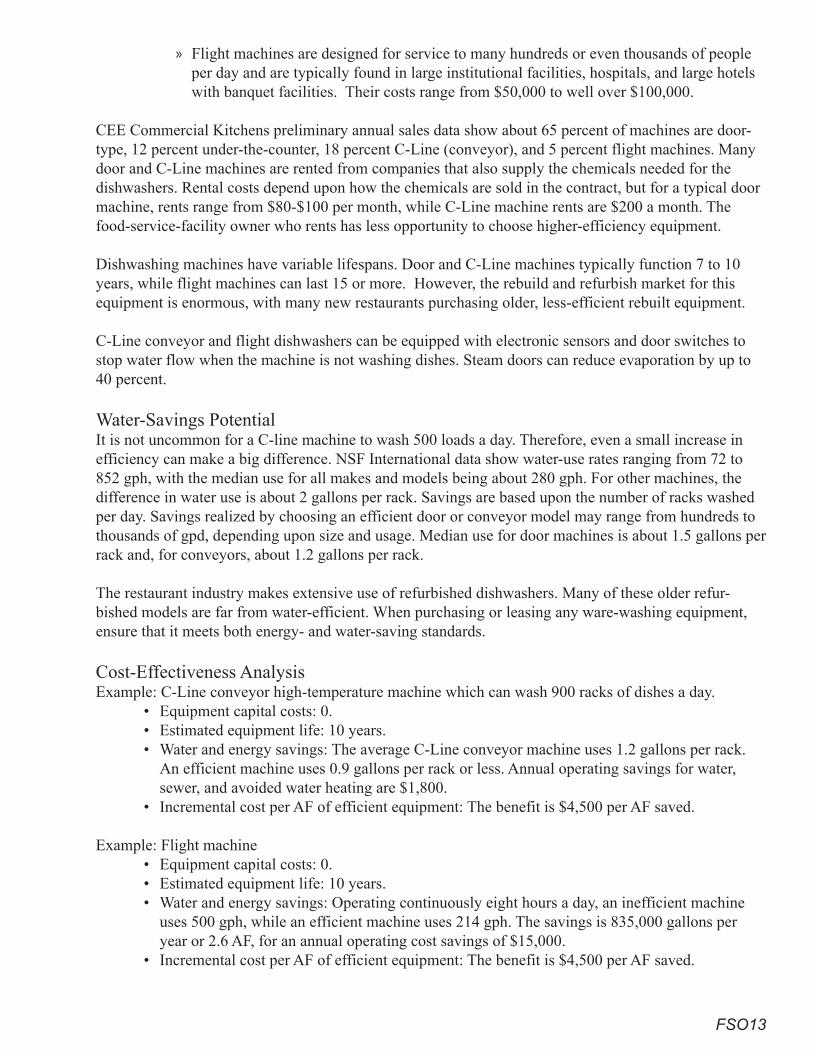
FSO13
Flight machines are designed for service to many hundreds or even thousands of people per day and are typically found in large institutional facilities, hospitals, and large hotels with banquet facilities. Their costs range from $50,000 to well over $100,000.
CEE Commercial Kitchens preliminary annual sales data show about 65 percent of machines are door-type, 12 percent under-the-counter, 18 percent C-Line (conveyor), and 5 percent flight machines. Many door and C-Line machines are rented from companies that also supply the chemicals needed for the dishwashers. Rental costs depend upon how the chemicals are sold in the contract, but for a typical door machine, rents range from $80-$100 per month, while C-Line machine rents are $200 a month. The food-service-facility owner who rents has less opportunity to choose higher-efficiency equipment.
Dishwashing machines have variable lifespans. Door and C-Line machines typically function 7 to 10 years, while flight machines can last 15 or more. However, the rebuild and refurbish market for this equipment is enormous, with many new restaurants purchasing older, less-efficient rebuilt equipment.
C-Line conveyor and flight dishwashers can be equipped with electronic sensors and door switches to stop water flow when the machine is not washing dishes. Steam doors can reduce evaporation by up to 40 percent.
Water-Savings PotentialIt is not uncommon for a C-line machine to wash 500 loads a day. Therefore, even a small increase in efficiency can make a big difference. NSF International data show water-use rates ranging from 72 to 852 gph, with the median use for all makes and models being about 280 gph. For other machines, the difference in water use is about 2 gallons per rack. Savings are based upon the number of racks washed per day. Savings realized by choosing an efficient door or conveyor model may range from hundreds to thousands of gpd, depending upon size and usage. Median use for door machines is about 1.5 gallons per rack and, for conveyors, about 1.2 gallons per rack.
The restaurant industry makes extensive use of refurbished dishwashers. Many of these older refur-bished models are far from water-efficient. When purchasing or leasing any ware-washing equipment, ensure that it meets both energy- and water-saving standards.
Cost-Effectiveness Analysis Example: C-Line conveyor high-temperature machine which can wash 900 racks of dishes a day.
• Equipment capital costs: 0.• Estimated equipment life: 10 years.• Water and energy savings: The average C-Line conveyor machine uses 1.2 gallons per rack.
An efficient machine uses 0.9 gallons per rack or less. Annual operating savings for water, sewer, and avoided water heating are $1,800.
• Incremental cost per AF of efficient equipment: The benefit is $4,500 per AF saved.
Example: Flight machine • Equipment capital costs: 0.• Estimated equipment life: 10 years.• Water and energy savings: Operating continuously eight hours a day, an inefficient machine
uses 500 gph, while an efficient machine uses 214 gph. The savings is 835,000 gallons per year or 2.6 AF, for an annual operating cost savings of $15,000.
• Incremental cost per AF of efficient equipment: The benefit is $4,500 per AF saved.
»
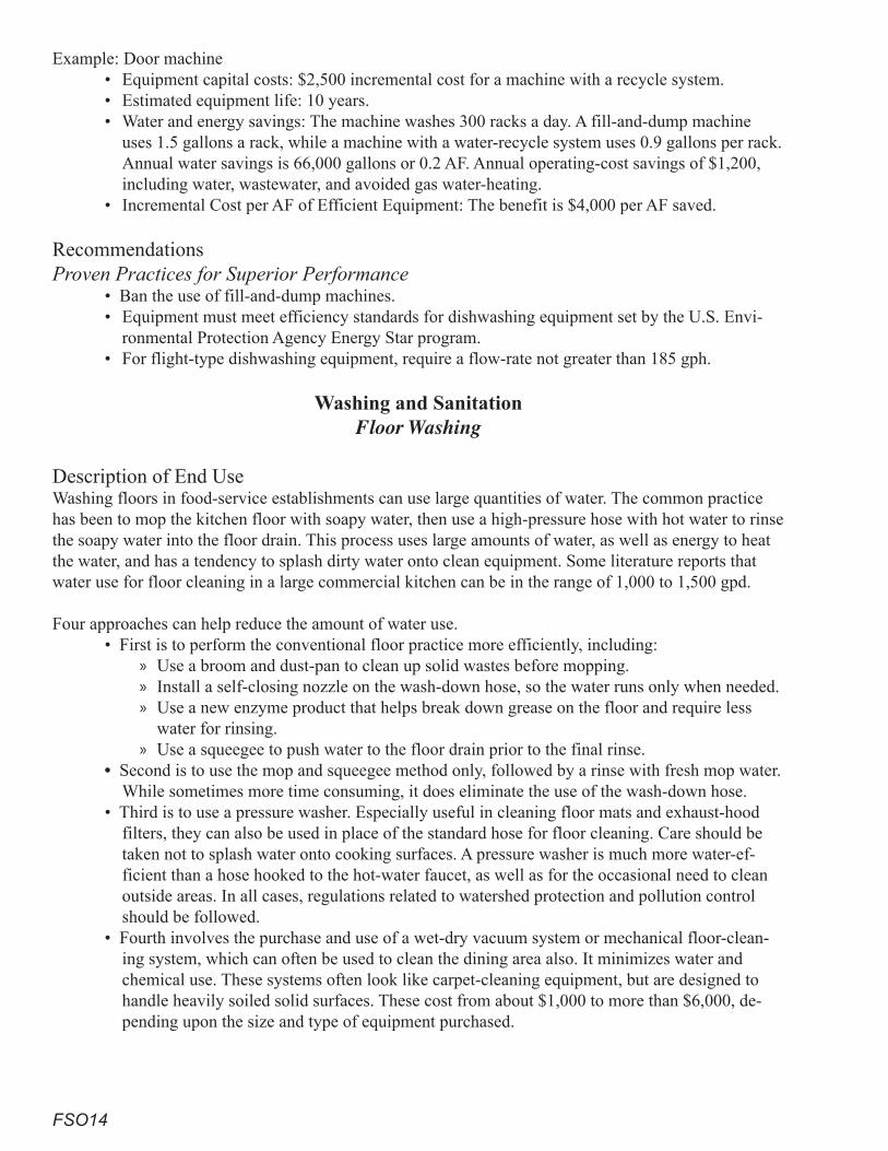
FSO14
Example: Door machine • Equipment capital costs: $2,500 incremental cost for a machine with a recycle system.• Estimated equipment life: 10 years.• Water and energy savings: The machine washes 300 racks a day. A fill-and-dump machine
uses 1.5 gallons a rack, while a machine with a water-recycle system uses 0.9 gallons per rack. Annual water savings is 66,000 gallons or 0.2 AF. Annual operating-cost savings of $1,200, including water, wastewater, and avoided gas water-heating.
• Incremental Cost per AF of Efficient Equipment: The benefit is $4,000 per AF saved.
RecommendationsProven Practices for Superior Performance
• Ban the use of fill-and-dump machines.• Equipment must meet efficiency standards for dishwashing equipment set by the U.S. Envi-
ronmental Protection Agency Energy Star program.• For flight-type dishwashing equipment, require a flow-rate not greater than 185 gph.
Washing and Sanitation Floor Washing
Description of End UseWashing floors in food-service establishments can use large quantities of water. The common practice has been to mop the kitchen floor with soapy water, then use a high-pressure hose with hot water to rinse the soapy water into the floor drain. This process uses large amounts of water, as well as energy to heat the water, and has a tendency to splash dirty water onto clean equipment. Some literature reports that water use for floor cleaning in a large commercial kitchen can be in the range of 1,000 to 1,500 gpd.
Four approaches can help reduce the amount of water use. • First is to perform the conventional floor practice more efficiently, including:
Use a broom and dust-pan to clean up solid wastes before mopping.Install a self-closing nozzle on the wash-down hose, so the water runs only when needed.Use a new enzyme product that helps break down grease on the floor and require less water for rinsing. Use a squeegee to push water to the floor drain prior to the final rinse.
• Second is to use the mop and squeegee method only, followed by a rinse with fresh mop water. While sometimes more time consuming, it does eliminate the use of the wash-down hose.
• Third is to use a pressure washer. Especially useful in cleaning floor mats and exhaust-hood filters, they can also be used in place of the standard hose for floor cleaning. Care should be taken not to splash water onto cooking surfaces. A pressure washer is much more water-ef-ficient than a hose hooked to the hot-water faucet, as well as for the occasional need to clean outside areas. In all cases, regulations related to watershed protection and pollution control should be followed.
• Fourth involves the purchase and use of a wet-dry vacuum system or mechanical floor-clean-ing system, which can often be used to clean the dining area also. It minimizes water and chemical use. These systems often look like carpet-cleaning equipment, but are designed to handle heavily soiled solid surfaces. These cost from about $1,000 to more than $6,000, de-pending upon the size and type of equipment purchased.
»»»
»
FSO1�
Water-Savings PotentialWhen examining ways to reduce water use at a new facility, the choice of floor-cleaning processes must be part of the facility design.
• Any conventional floor cleaning system with a hot-water hose should, at a minimum, have a self-closing valve.
• Choose pressure-washing equipment for floor, exhaust-hood-filter, and floor-mat washing.• Arrange equipment so squeegeeing can be done easily.• Use floor-cleaning machines that have a water tank. • Consider a floor washer or other systems.
Traditional floor-washing systems can use 1,250 gpd. A water-broom and mop system will cut this to un-der 500 gpd, and a floor-washing system or machine can reduce this to under 250 gallons, for a savings of 750 to 1,000 gpd of hot water. It is difficult to estimate water savings exactly, since it depends upon many parameters and must be done on a case-by-case basis.
Cost-Effectiveness Analysis • Equipment capital costs: N/A• Estimated equipment life: N/A• Water and energy savings: The cost effectiveness of these systems is strongly dependent upon
the individual situation. A range for savings would be $2,000 to $3,500 per year.• Incremental cost per AF of efficient equipment: N/A
RecommendationsProven Practices for Superior Performance
• Require all hoses used for washdown to have self-closing nozzles and limit flow to no more than five gpm.
Additional Practices That Achieve Significant Savings• Use water brooms that are limited to 3.0 gpm where feasible.• Use a floor-cleaning machine.• Use an enzyme cleaning processes.• Choose pressure-washing equipment for floor, exhaust-hood-filter, and floor-mat washing.• Arrange equipment so squeegeeing can be done easily.
Hood Washing
Hood-washer systems offer a convenient way to clean slot and extractor hoods. The hood washer sprays soapy hot water over the grease-extractor systems after the hood is turned off for the day. Timing can be pre-set depending upon the amount of grease that collects. Hood-washer systems use from 0.5 to 1.0 gpm of water per linear foot. Hood washers may or may not use less water than conventional manual cleaning methods, depending upon the frequency of washing and how the water use with the hood sys-tem compares with the water use of manual cleaning, usually done with a pressure washer. Hood sys-tems have a significant cost, although when properly operated, they may save water.
ReferencesAlto-Shaam. Combitherm. www.auto-shaam.com.
Bowser, Tim, P.E. Food Technology Fact Sheet.
Energy Star. Energy Star Calculator. www.EnergyStar.gov.
FSO16
__________. www.EnergyStar.gov/ia/products/commercial_food_service/CFS_Full_Service.xls.
Fisher-Nickle Inc. February 2005. Best Practices – How to Achieve the Most Efficient Uses of Water in Commercial Food Service Facilities.
__________. www.fishnick.com.
__________. www.fishnick.com/saveenergy/rebates/combis/combis.pdf.
Reed, Clark. October 2005. Saving Water Counts in Energy Efficiency. Energy Star. U.S. Environ-mental Protection Agency.
Sydney Water Australia. September 1, 2005. Wok Stove and Steamer Water Efficiency Report.
Sorensen, Greg. July 2006. Rational Model SCC 62G Combination Oven Performance Test. Food Service Technology Center. Fisher-Nickel, Inc.
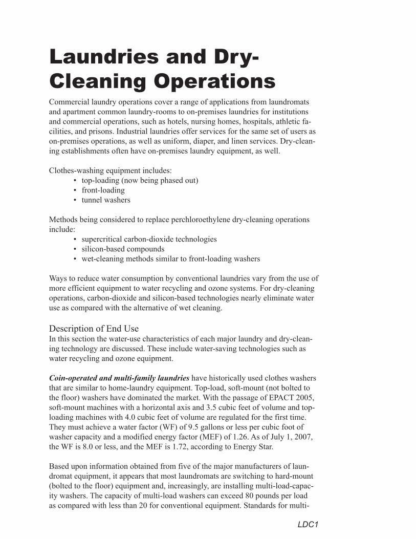
LDC1
Laundries and Dry- Cleaning OperationsCommercial laundry operations cover a range of applications from laundromats and apartment common laundry-rooms to on-premises laundries for institutions and commercial operations, such as hotels, nursing homes, hospitals, athletic fa-cilities, and prisons. Industrial laundries offer services for the same set of users as on-premises operations, as well as uniform, diaper, and linen services. Dry-clean-ing establishments often have on-premises laundry equipment, as well.
Clothes-washing equipment includes:• top-loading (now being phased out)• front-loading• tunnel washers
Methods being considered to replace perchloroethylene dry-cleaning operations include:
• supercritical carbon-dioxide technologies• silicon-based compounds• wet-cleaning methods similar to front-loading washers
Ways to reduce water consumption by conventional laundries vary from the use of more efficient equipment to water recycling and ozone systems. For dry-cleaning operations, carbon-dioxide and silicon-based technologies nearly eliminate water use as compared with the alternative of wet cleaning.
Description of End UseIn this section the water-use characteristics of each major laundry and dry-clean-ing technology are discussed. These include water-saving technologies such as water recycling and ozone equipment.
Coin-operated and multi-family laundries have historically used clothes washers that are similar to home-laundry equipment. Top-load, soft-mount (not bolted to the floor) washers have dominated the market. With the passage of EPACT 2005, soft-mount machines with a horizontal axis and 3.5 cubic feet of volume and top-loading machines with 4.0 cubic feet of volume are regulated for the first time. They must achieve a water factor (WF) of 9.5 gallons or less per cubic foot of washer capacity and a modified energy factor (MEF) of 1.26. As of July 1, 2007, the WF is 8.0 or less, and the MEF is 1.72, according to Energy Star.
Based upon information obtained from five of the major manufacturers of laun-dromat equipment, it appears that most laundromats are switching to hard-mount (bolted to the floor) equipment and, increasingly, are installing multi-load-capac-ity washers. The capacity of multi-load washers can exceed 80 pounds per load as compared with less than 20 for conventional equipment. Standards for multi-
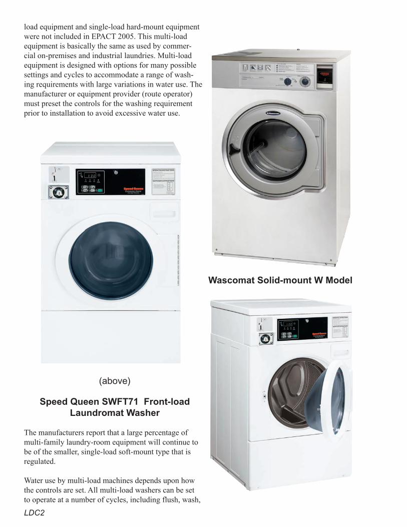
LDC2
load equipment and single-load hard-mount equipment were not included in EPACT 2005. This multi-load equipment is basically the same as used by commer-cial on-premises and industrial laundries. Multi-load equipment is designed with options for many possible settings and cycles to accommodate a range of wash-ing requirements with large variations in water use. The manufacturer or equipment provider (route operator) must preset the controls for the washing requirement prior to installation to avoid excessive water use.
Wascomat Solid-mount W Model
(above)
Speed Queen SWFT71 Front-load Laundromat Washer
The manufacturers report that a large percentage of multi-family laundry-room equipment will continue to be of the smaller, single-load soft-mount type that is regulated.
Water use by multi-load machines depends upon how the controls are set. All multi-load washers can be set to operate at a number of cycles, including flush, wash,
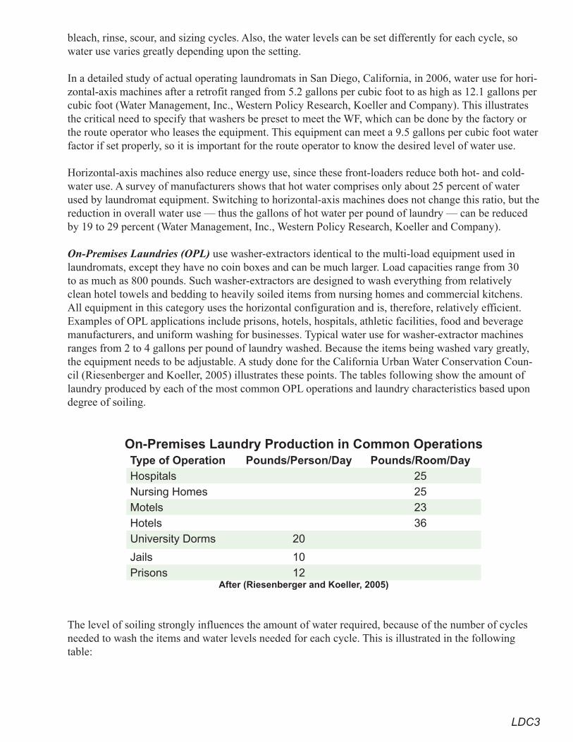
LDC3
bleach, rinse, scour, and sizing cycles. Also, the water levels can be set differently for each cycle, so water use varies greatly depending upon the setting.
In a detailed study of actual operating laundromats in San Diego, California, in 2006, water use for hori-zontal-axis machines after a retrofit ranged from 5.2 gallons per cubic foot to as high as 12.1 gallons per cubic foot (Water Management, Inc., Western Policy Research, Koeller and Company). This illustrates the critical need to specify that washers be preset to meet the WF, which can be done by the factory or the route operator who leases the equipment. This equipment can meet a 9.5 gallons per cubic foot water factor if set properly, so it is important for the route operator to know the desired level of water use.
Horizontal-axis machines also reduce energy use, since these front-loaders reduce both hot- and cold-water use. A survey of manufacturers shows that hot water comprises only about 25 percent of water used by laundromat equipment. Switching to horizontal-axis machines does not change this ratio, but the reduction in overall water use — thus the gallons of hot water per pound of laundry — can be reduced by 19 to 29 percent (Water Management, Inc., Western Policy Research, Koeller and Company).
On-Premises Laundries (OPL) use washer-extractors identical to the multi-load equipment used in laundromats, except they have no coin boxes and can be much larger. Load capacities range from 30 to as much as 800 pounds. Such washer-extractors are designed to wash everything from relatively clean hotel towels and bedding to heavily soiled items from nursing homes and commercial kitchens. All equipment in this category uses the horizontal configuration and is, therefore, relatively efficient. Examples of OPL applications include prisons, hotels, hospitals, athletic facilities, food and beverage manufacturers, and uniform washing for businesses. Typical water use for washer-extractor machines ranges from 2 to 4 gallons per pound of laundry washed. Because the items being washed vary greatly, the equipment needs to be adjustable. A study done for the California Urban Water Conservation Coun-cil (Riesenberger and Koeller, 2005) illustrates these points. The tables following show the amount of laundry produced by each of the most common OPL operations and laundry characteristics based upon degree of soiling.
On-Premises Laundry Production in Common OperationsType of Operation Pounds/Person/Day Pounds/Room/DayHospitals 25Nursing Homes 25Motels 23Hotels 36University Dorms 20
Jails 10Prisons 12
After (Riesenberger and Koeller, 2005)
The level of soiling strongly influences the amount of water required, because of the number of cycles needed to wash the items and water levels needed for each cycle. This is illustrated in the following table:
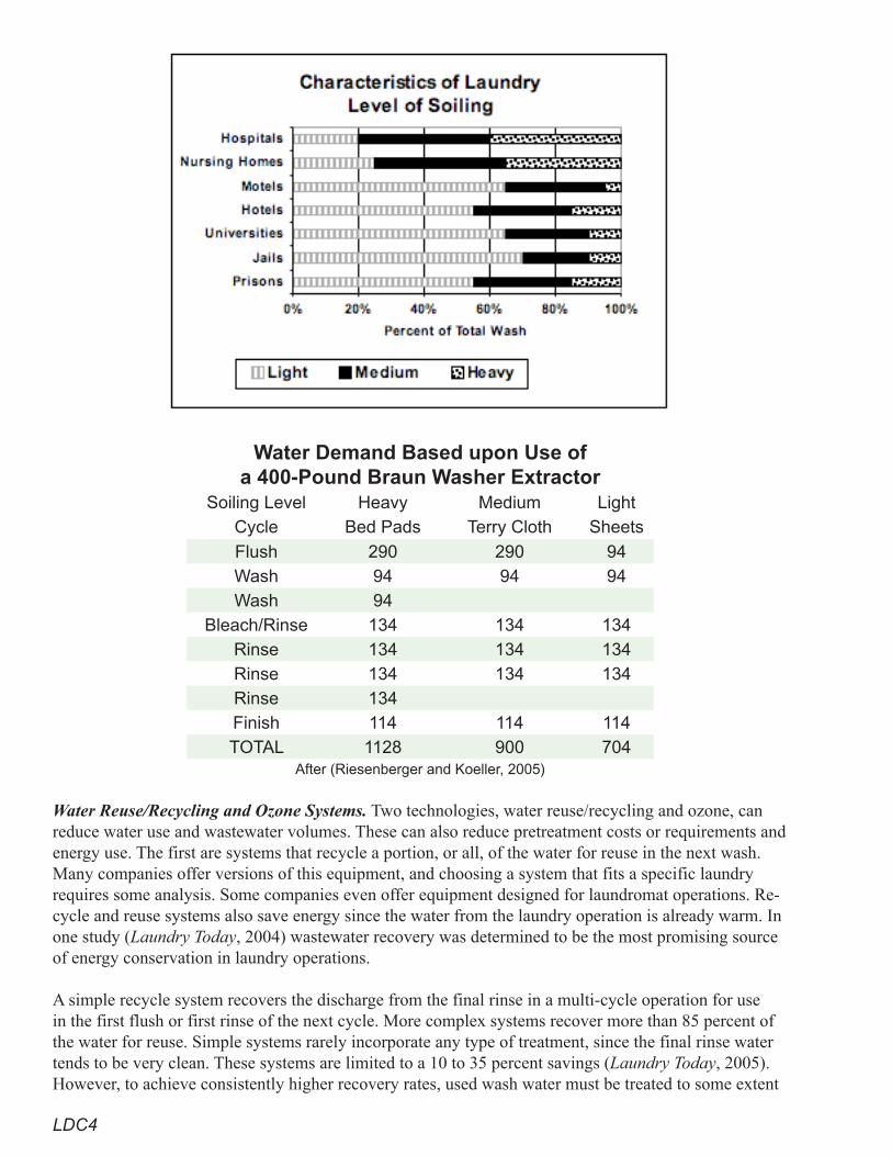
LDC4
Water Demand Based upon Use of a 400-Pound Braun Washer Extractor
Soiling Level Heavy Medium LightCycle Bed Pads Terry Cloth Sheets
Flush 290 290 94Wash 94 94 94Wash 94
Bleach/Rinse 134 134 134Rinse 134 134 134Rinse 134 134 134Rinse 134Finish 114 114 114TOTAL 1128 900 704
After (Riesenberger and Koeller, 2005)
Water Reuse/Recycling and Ozone Systems. Two technologies, water reuse/recycling and ozone, can reduce water use and wastewater volumes. These can also reduce pretreatment costs or requirements and energy use. The first are systems that recycle a portion, or all, of the water for reuse in the next wash. Many companies offer versions of this equipment, and choosing a system that fits a specific laundry requires some analysis. Some companies even offer equipment designed for laundromat operations. Re-cycle and reuse systems also save energy since the water from the laundry operation is already warm. In one study (Laundry Today, 2004) wastewater recovery was determined to be the most promising source of energy conservation in laundry operations.
A simple recycle system recovers the discharge from the final rinse in a multi-cycle operation for use in the first flush or first rinse of the next cycle. More complex systems recover more than 85 percent of the water for reuse. Simple systems rarely incorporate any type of treatment, since the final rinse water tends to be very clean. These systems are limited to a 10 to 35 percent savings (Laundry Today, 2005). However, to achieve consistently higher recovery rates, used wash water must be treated to some extent
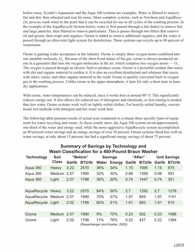
LDC�
before reuse. Ecolab’s Aquamiser and the Aqua 360 systems are examples. Water is filtered to remove lint and dirt, then reheated and sent for reuse. More complete systems, such as Norchem and AquaRecy-cle, process wash water to the point that it can be recycled for use in all cycles of the washing process. In the example of the AquaRecycle System below, water is first passed through a lint shaker to remove lint and large particles, then filtered to remove particulates. Then it passes through two filters that remove oil and grease, then soaps and organics. Ozone is added to remove additional organics, and the water is passed through an ultraviolet light system for disinfection. These systems can recycle up to 90 percent of wastewater.
Ozone is gaining wider acceptance in the industry. Ozone is simply three oxygen atoms combined into one unstable molecule, O
3. Because of the short-lived nature of the gas, ozone is always produced on-
site in a generator that uses the oxygen molecules in the air, which comprise two oxygen atoms — O2.
The oxygen is passed through an electric field to produce ozone. Ozone is a powerful oxidant that reacts with dirt and organic material to oxidize it. It is also an excellent disinfectant and whitener that reacts with odors, stains, and other organic material in the wash. Ozone is quickly converted back to oxygen gas in the washing process. Unlike ozone in the upper atmosphere, it lasts for only a short time in laun-dry applications.
With ozone, water temperatures can be reduced, since it works best at around 80° F. This significantly reduces energy use. It also allows for reduced use of detergents and chemicals, so less rinsing is needed thus less water. Ozone systems work well on lightly soiled clothes. For heavily soiled laundry, conven-tional wet methods with detergent and hot water work best.
The following table presents results of actual tests conducted to evaluate three specific types of equip-ment for water recycling and ozone. As these results show, the Aqua 360 system saved approximately one-third of the water and energy used, while the more aggressive AquaRecycle system accomplished an 80 percent water savings and an energy savings of over 50 percent. Ozone systems fared less well on water savings, at only about 15 percent, but had a significant energy savings of about 75 percent.
Summary of Savings by Technology and Wash Classification for a 400-Pound Braun Washer
Technology SoilClass
“Before” Savings “After” Unit SavingsGal/lb BTU/lb Water Energy Gal/lb BTU/lb Gal/lb BTU/lb
Aqua 360 Heavy 3.22 2570 36% 34% 1.15 1695 1.15 875
Aqua 360 Medium 2.57 1990 32% 30% 0.88 1399 0.88 591
Aqua 360 Light 2.07 1798 36% 20% 0.74 1447 0.74 351
AquaRecycle Heavy 3.22 2570 84% 50% 2.7 1292 2.7 1278
AquaRecycle Medium 2.57 1990 70% 57% 1.97 849 1.97 1141
AquaRecycle Light 2.02 1798 80% 51% 1.61 883 1.61 915
Ozone Medium 2.57 1990 9% 75% 0.23 502 0.23 1488
Ozone Light 2.02 1798 11% 76% 0.22 427 0.22 1364 (Riesenberger and Koeller, 2005)
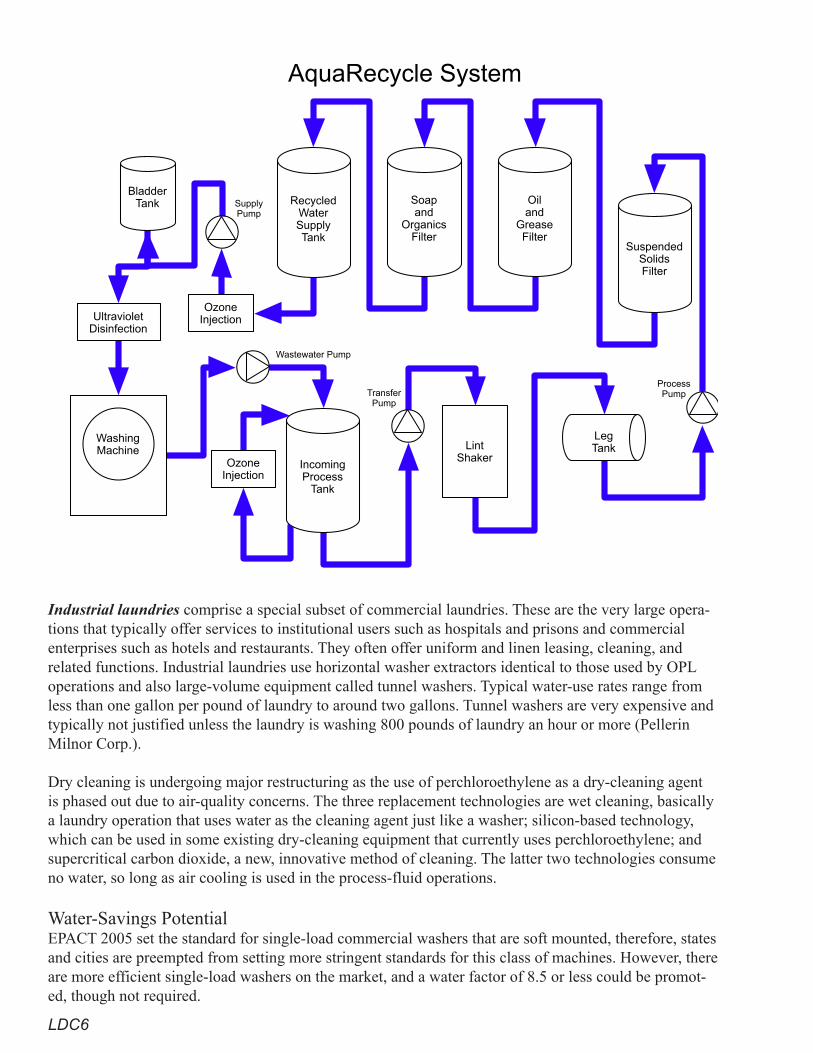
LDC6
Industrial laundries comprise a special subset of commercial laundries. These are the very large opera-tions that typically offer services to institutional users such as hospitals and prisons and commercial enterprises such as hotels and restaurants. They often offer uniform and linen leasing, cleaning, and related functions. Industrial laundries use horizontal washer extractors identical to those used by OPL operations and also large-volume equipment called tunnel washers. Typical water-use rates range from less than one gallon per pound of laundry to around two gallons. Tunnel washers are very expensive and typically not justified unless the laundry is washing 800 pounds of laundry an hour or more (Pellerin Milnor Corp.). Dry cleaning is undergoing major restructuring as the use of perchloroethylene as a dry-cleaning agent is phased out due to air-quality concerns. The three replacement technologies are wet cleaning, basically a laundry operation that uses water as the cleaning agent just like a washer; silicon-based technology, which can be used in some existing dry-cleaning equipment that currently uses perchloroethylene; and supercritical carbon dioxide, a new, innovative method of cleaning. The latter two technologies consume no water, so long as air cooling is used in the process-fluid operations.
Water-Savings Potential EPACT 2005 set the standard for single-load commercial washers that are soft mounted, therefore, states and cities are preempted from setting more stringent standards for this class of machines. However, there are more efficient single-load washers on the market, and a water factor of 8.5 or less could be promot-ed, though not required.
RecycledWaterSupplyTank
Soapand
OrganicsFilter
Oiland
GreaseFilter
SuspendedSolidsFilter
IncomingProcess
Tank
LegTankLint
Shaker
BladderTank
OzoneInjectionUltraviolet
Disinfection
WashingMachine
OzoneInjection
AquaRecycle System
Wastewater Pump
TransferPump
ProcessPump
SupplyPump
LDC7
Since there is no federal standard for single-load washers that are hard mounted or any of the multi-load washers, states and cities can set local standards. A minimum standard WF would be 9.5, but there are enough single-load hard-mount models available to support a local WF standard of between 8 and 8.5.
Multi-load machines can use as much as 12 gallons per cubic foot and range in size from 4 to 12 cubic feet. Water savings of 5 to 20 gallons a load can be achieved by having a local standard of 9.5 gallons per cubic foot.
Tunnel washers can cut water use per pound of laundry by 30 to 60 percent.
Water-recycling equipment can recycle from 10 to 90 percent of the wash water, depending upon the level of treatment provided, and conserves energy by recycling warm water. Ozone equipment reduces water use by 10 to 25 percent, but can also significantly reduce energy and chemical use.
Among the replacements for conventional dry cleaning, the wet-cleaning method uses washer equipment almost identical to normal horizontal washers and uses water in the process. Volumes per cubic foot are lower that those for conventional washer operations, but water is still used. The silicon-based and car-bon-dioxide systems do not use water.
Cost-Effectiveness Analysis Cost analysis considers many variables. Hard-mount equipment is slightly less costly than soft-mount equipment of the same capacity, because it does not need the suspension equipment to allow for high gravity-forced spin speeds. Hard-mount systems can also take advantage of gravity dumping of wash water. These cost differences are small in comparison to overall costs.
Tunnel washers cost hundreds of thousands of dollars, but are designed for efficient washing of large volumes of laundry with lower energy and half the water use. To be cost-effective, most manufacturers recommend that the throughput be in excess of 800 pounds an hour.
To make recycling systems economically viable, the combined water and wastewater costs generally have to be greater than $4 per thousand gallons.
The AquaRecycle system costs about $100,000 for a system capable of recycling 15 gpm and more than $330,000 for a system capable of recycling 250 gpm. This equals about $12 per nominal pound of ca-pacity. The AquaTex 360 costs slightly less, about $9.50 per nominal pound of capacity. Ozone systems cost from $10,000 to $45,000 per unit, depending upon size.
RecommendationsProven Practices for Superior Performance
• Require all single-load hard-mount laundromat or other coin- and card-operated machines to have a WF of 8.0 or less.
• Require all multi-load coin- and card-operated machines to have a WF of 9.5 or less and be installed with proper settings to achieve the required WF.
Additional Practices That Achieve Significant Savings• Promote a WF of 8.0 or less for single-load soft-mount washers. • Encourage the use of recycle/reuse or ozone equipment when feasible.• Encourage the use of tunnel washers wherever laundry volume is sufficient.• Encourage the use of non-wet dry-cleaning.
LDC8
References“Energy Utilization.” Laundry Today. July/August 2004.
Pellerin Milnor Corp. www.milnor.com/.
Riesenberger, James, and Koeller, John. November 2005. Commercial Laundry Facilities.
San Diego Water Authority, Water Management, Inc., Western Policy Research, and Koeller and Compa-ny. 2006 Report on the Monitoring and Assessment of Water Savings from the Coin-Operated Multi-Load Clothes Washers Voucher Initiative Program.
“Slash Utility Consumption.” Laundry Today. July/August 2005, p. 12.
MIU1
Metering of Individual Units
Metering of Individual Dwelling Units at Apartments, Condominiums, Townhouses, Mobile-home Parks, and
Commercial FacilitiesMost water providers currently bill apartments, condominiums, townhouses, mo-bile-home parks, and commercial properties through one or several master meters. Occupants do not receive a water bill from the water provider directly. Since these charges are included in the occupant’s monthly rent, there is little financial incen-tive to use water efficiently or to report leaks. This tendency may be exacerbated during water shortages, when requests by the water provider to curtail usage are not directly conveyed to the occupants or can be easily dismissed. Therefore, a water provider may wish to implement a program to meter individual units in new multi-family and commercial properties to capture the water-saving benefits. In fact, one state now requires all new apartments, condominiums, and mixed-use units to be plumbed for meters and proposed local regulations would require water billing in new apartments and mixed-use buildings to be based upon actual metering and not allocation. Since submetering is considered as any metering that occurs downstream of a master meter, a water-provider program to meter individ-ual units is not really considered submetering if no master meter is used.
Water Savings and Other BenefitsA national study on [submetering and allocation programs conducted in 2004 found 15 percent water savings (8,000 gallons per dwelling unit) and 21 percent indoor energy savings associated with [submetering by third-party billing entities (non-water providers) at existing multi-family buildings. In new construction, the savings is estimated to be approximately 6,000 gallons per dwelling unit, due to the installation of water-efficient fixtures required by the plumbing code. At sites where the occupants also have some landscaping, such as condominiums, town-houses, and mobile-home parks, the water savings is estimated at 20 percent.
Benefits to the property owner include not having to pay or divide up the water bill and controlling water (and wastewater) costs that are typically exceeding the rate of inflation. The benefits to the occupants are the water (and energy) savings and paying only for the water they use. The water provider will benefit through reduced operating costs and, due to direct pricing signals, the potential for better response in water-shortage emergencies.
Metering other end uses at multi-family and commercial properties, such as landscape irrigation and cooling-tower make-up and blowdown, also has benefits. Metering landscape irrigation allows for water budgets which can benefit both the water provider and the property owner. A growing trend is for water providers to require developers to install separate meters for irrigation in order to manage
MIU2
irrigation water use. In California new properties with 5,000 square feet or more of landscaping are now required to be separately metered.
Installing meters on individual units in commercial buildings can benefit customers where, in some cit-ies, they are not charged wastewater fees for evaporated water from cooling towers if the cooling-tower make-up and blowdown water are metered. The same meters can be used to determine cooling-tower cycles of concentration, so operating improvements can be made. Commercial properties typically hav-ing only one meter serving multiple occupants include:
• mixed-use facilities with, for example, retail on the first floor and condos or apartments on the upper floors
• shopping and business centers• airports that have restaurants and other vendors• marinas
Metering, Billing, and Other Issues
Plumbing Configuration A building’s height and water-heating system usually determine its plumbing configuration. For ex-ample, if each unit in a building has a water heater, each unit can be served by one cold-water line. This means that just one meter is needed to record all of that unit’s water use. However, in buildings with a common water heater (boiler), each unit is served by two water lines: one for cold water and one for hot water. Thus, two meters are needed to record all the water use in that unit. This makes metering much more expensive, since not only are two meters needed, but an approved meter is needed for the hot-wa-ter line. A meter approved for up to 250° F should be used; these cost approximately $100 more than cold-water meters. Alternatively just the cold-water line into each unit might be metered, and occupants may be billed for only the cold-water use, which is estimated to be 70 percent of the total. The cold-wa-ter line entering the boiler would be metered and the property owner billed for that use. Thus, all use on the property can still be metered using cold-water meters.
Meter LocationWater providers can require multi-family buildings to have a water meter installed for each unit. For most multi-family buildings up to three stories, meters can be clustered outside the building in a vault. For buildings higher than three stories, it is not practical to have meters placed on the ground level, since that would require placing the water lines in the walls of the building in long runs up to each floor. An alternative is to install meters in utility rooms on various floors. For example, in a 12-story building, banks of meters could be installed outside the building at ground level to serve the first three floors and in utility rooms on the 5th, 8th, and 11th floors (with each utility room having a bank of meters serving three floors). The meters could then be monitored using remote-read technology. If a water provider were responsible for the meters and the reading-and-billing program, they would need to address meter-accessibility (for meter servicing and turning meters on and off) and liability (leak) issues. For example, all utility rooms should have floor drains in case of leaks. The costs to the developer/owner to meter oc-cupants in buildings higher than three stories will increase by approximately $300 to $400 per dwelling unit over three stories or less due to the issues cited above.
AdministrationWhile it is assumed that the water provider will administer an expanded metering and read-and-bill pro-gram targeting this sector, that may not always be the case. However, since third-party billing is primar-ily unregulated, if a third party administers a program, the water provider should have adopted appro-priate regulations governing billing services, such as bill format and information provided, prohibiting
MIU3
resale of water at a profit, service charges, late fees, complaint resolution, customer services, etc., unless regulations have already been adopted at the county or state level.
Mixed-Use Development, Business Centers, and MallsMany mixed-use buildings being developed today have retail or other types of enterprises on the first floor and condominiums or office space on the upper floors. Submetering, with billing based upon actual water use, is much more equitable for customers in such buildings, where water usage can vary greatly among tenants.
At master-metered business parks and centers, it may be difficult for source-control representatives to determine the type of business in each space. This may lead to unmonitored and unregulated discharges and lost discharge fees. Therefore, another benefit of metering individual units/spaces at business parks is better regulation of wastewater discharges, where business effluents may go undetected. Requiring individual water meters for these occupants could eliminate or reduce these issues, especially if there is communication between the water provider and the wastewater authority.
Cost-Effectiveness AnalysisProgram costs and benefits can be assessed from four perspectives:
• the builder/owner• the water provider• the occupant • the community
It is usually more cost-effective to meter individual units in buildings of less than four stories because the meter can be located outside the building at ground level. It is also more-cost effective, in terms of capturing water savings, to meter those units (condominiums, townhouses, mobile-home parks) where the occupant is also responsible for outdoor irrigation.
Builder/Owner The cost of requiring the owner to meter new construction can vary considerably and is estimated at $100 to $500 per dwelling unit, considering space for the meters, their installation, and meter-reading equipment (if appropriate), the potential need for utility rooms, and the type of meter-reading program and its associated hardware/software. These costs could be partially or totally offset by connection fee (also known as a system-capacity charge) credits due to projections of lower water use related to the metering program.
OccupantOccupants save on both water and energy use. Average water savings is estimated at 15 percent and av-erage energy savings at 21 percent. The value of these savings will vary from region to region depending upon water and energy costs. However, these may be partially or completely offset by service charges associated with the cost of the metering program.
Water ProviderThe water provider will realize various benefits through certain avoided costs (reduced operating costs and potentially reduced capital costs). Water-provider costs are passed on to end users through the water rates in service and volume charges.
MIU4
CommunityFrom the community perspective, program benefits, which include customer water and energy savings, the utility’s avoided costs, and improved water-consumption-management capability for the utility dur-ing water shortages, approximately equal program costs (meters, meter installation, reading and billing, and customer service). Community costs and benefits, while roughly estimated to be about equal, are dependent upon a number of variables, such as the value of the saved water to the utility, the cost of the metering program, and the value of improved response from this sector during a water-shortage emer-gency. These need to be assessed for merit by each water provider.
RecommendationsProven Practices for Superior Performance
• Incorporate submeters for make-up and blowdown water in new cooling-tower installations.• Install separate irrigation meters at new non-single-family properties with 2,500 square feet or
more of irrigated landscape.Additional Practices That Achieve Significant Savings
• Meter individual units in new apartments, condominiums, townhouses, mobile-home parks, and mixed-use buildings of less than four stories.
• Meter individual units at commercial centers.
ReferencesAquacraft. 2004. National Multiple Family Submetering and Allocation Program Study. www.aqua-
craft.com/Projects/submeter.htm.
City of Austin, Texas. December 16, 1999 (adopted). “Installation of Water Meters,” Section 2.3.3. Wa-ter and Wastewater Criteria Manual.
City of Austin, Texas. May 3, 2007. Water Conservation Task Force Water Conservation Strategies Policy Document, Recommendation IN-2, p. 10.
East Bay Municipal Utility District. September 2006. Metering Program for New Non-Single Family Dwelling Units: Findings, Conclusions, and Recommendations.
Miami-Dade County Consumer Services Department. 1996. Miami-Dade County Water Remetering Ordinance, 96-137.
Texas Commission on Environmental Quality. April 13, 2005 (adopted). “Utility Submetering and Al-location,” Utility Regulations, Chapter 291, Subchapter H.
PW1
Process Water
Water used by industries and businesses to produce a product or affect a process is known as “process water.” This section discusses the following industries and their uses of process water:
• food and beverages• auto repair and service• paper manufacturing• metal finishing
The chapter will not cover opportunities to save water by using efficient plumbing fixtures and irrigation systems, since these are covered elsewhere in this report.
While much of the information herein is specific to the product being manufac-tured or service being provided, the potential to design water conservation into the process ranges from simply adjusting the equipment or process to use less water to adopting new practices or processes that use no water at all.
Food-and-Beverage ProcessingThe food-and-beverage-processing industry includes a wide range of products and manufacturing processes:
• bakery/pastry shops• industrial bakeries• breweries• wineries• soft drink and juice manufacturers• dairy-food processors• meat, fish, and poultry processing• frozen-food producers• canneries • snack-food manufacturers• grocery stores and restaurants that produce food products for sale• other food and drink processors
The food-and-beverage industry uses water for many purposes. The quality and purity of the water is of primary concern since it is used to make products that will be consumed. Water is also used to clean and sanitize floors, processing equipment, containers, vessels, and the raw food products prior to their process-ing. Hot water, steam, cooling, and refrigeration also require source water. De-signing and building a facility that has a reduced requirement for water includes:
• designing the facility for ease of cleaning• providing adequate metering, submetering, and process control• taking advantage of dry methods for cleanup and transport• using product- and byproduct-recovery systems
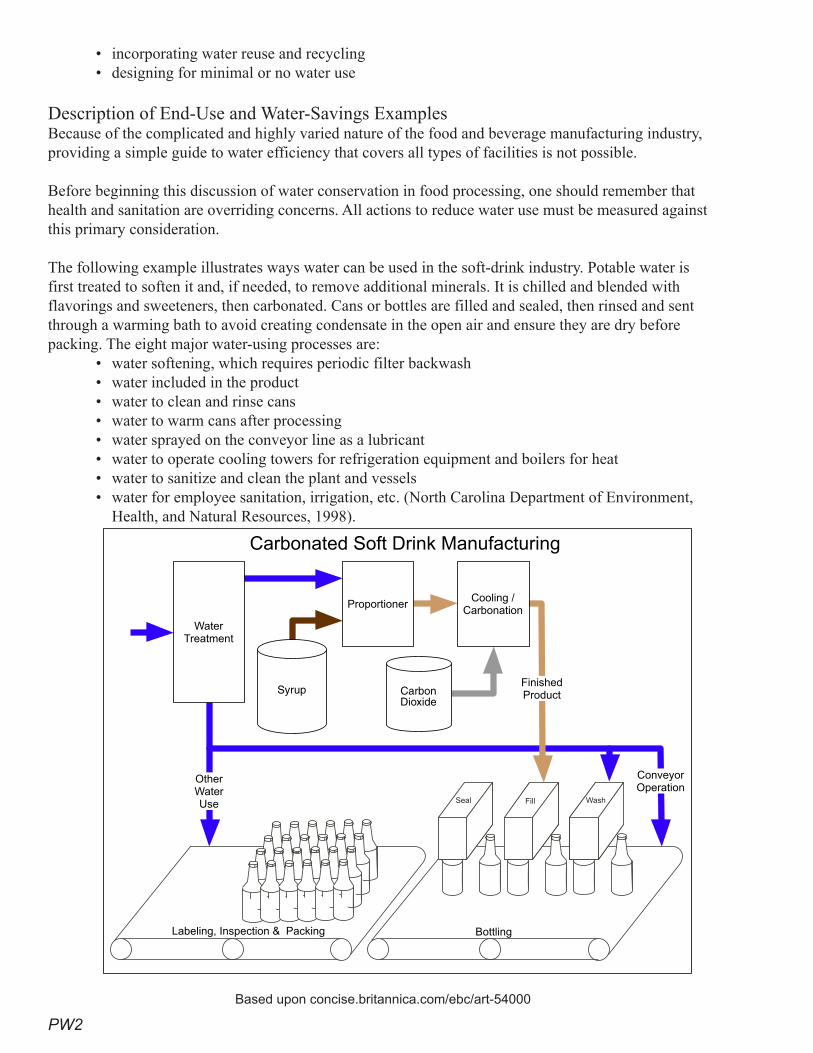
PW2
• incorporating water reuse and recycling• designing for minimal or no water use
Description of End-Use and Water-Savings ExamplesBecause of the complicated and highly varied nature of the food and beverage manufacturing industry, providing a simple guide to water efficiency that covers all types of facilities is not possible.
Before beginning this discussion of water conservation in food processing, one should remember that health and sanitation are overriding concerns. All actions to reduce water use must be measured against this primary consideration.
The following example illustrates ways water can be used in the soft-drink industry. Potable water is first treated to soften it and, if needed, to remove additional minerals. It is chilled and blended with flavorings and sweeteners, then carbonated. Cans or bottles are filled and sealed, then rinsed and sent through a warming bath to avoid creating condensate in the open air and ensure they are dry before packing. The eight major water-using processes are:
• water softening, which requires periodic filter backwash• water included in the product• water to clean and rinse cans• water to warm cans after processing• water sprayed on the conveyor line as a lubricant• water to operate cooling towers for refrigeration equipment and boilers for heat • water to sanitize and clean the plant and vessels• water for employee sanitation, irrigation, etc. (North Carolina Department of Environment,
Health, and Natural Resources, 1998).
Carbonated Soft Drink Manufacturing
Syrup CarbonDioxide
Proportioner
������������
Labeling, Inspection & Packing Bottling
ConveyorOperation
FinishedProduct
Cooling / Carbonation
WaterTreatment
OtherWaterUse
Based upon concise.britannica.com/ebc/art-54000
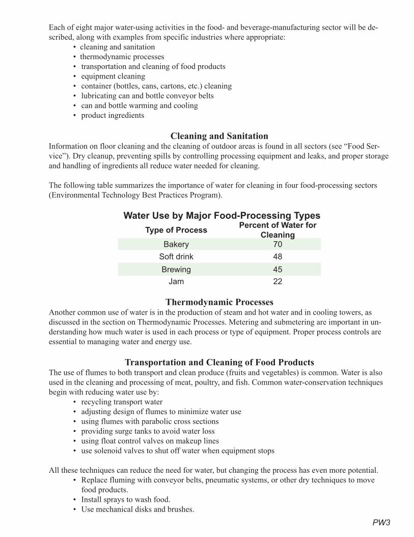
PW3
Each of eight major water-using activities in the food- and beverage-manufacturing sector will be de-scribed, along with examples from specific industries where appropriate:
• cleaning and sanitation• thermodynamic processes• transportation and cleaning of food products • equipment cleaning• container (bottles, cans, cartons, etc.) cleaning• lubricating can and bottle conveyor belts• can and bottle warming and cooling • product ingredients
Cleaning and SanitationInformation on floor cleaning and the cleaning of outdoor areas is found in all sectors (see “Food Ser-vice”). Dry cleanup, preventing spills by controlling processing equipment and leaks, and proper storage and handling of ingredients all reduce water needed for cleaning.
The following table summarizes the importance of water for cleaning in four food-processing sectors (Environmental Technology Best Practices Program).
Water Use by Major Food-Processing Types
Type of ProcessPercent of Water for
CleaningBakery 70
Soft drink 48
Brewing 45
Jam 22
Thermodynamic Processes Another common use of water is in the production of steam and hot water and in cooling towers, as discussed in the section on Thermodynamic Processes. Metering and submetering are important in un-derstanding how much water is used in each process or type of equipment. Proper process controls are essential to managing water and energy use.
Transportation and Cleaning of Food Products The use of flumes to both transport and clean produce (fruits and vegetables) is common. Water is also used in the cleaning and processing of meat, poultry, and fish. Common water-conservation techniques begin with reducing water use by:
• recycling transport water• adjusting design of flumes to minimize water use• using flumes with parabolic cross sections• providing surge tanks to avoid water loss• using float control valves on makeup lines• use solenoid valves to shut off water when equipment stops
All these techniques can reduce the need for water, but changing the process has even more potential. • Replace fluming with conveyor belts, pneumatic systems, or other dry techniques to move
food products.• Install sprays to wash food.• Use mechanical disks and brushes.

PW4
• Install counter-flow washing systems.• Control sprays on belts.• Control process equipment to reduce waste.
Grocery stores and smaller bakeries should follow good food-service sector washing practices for meats, fruits, vegetables, and other food products before final packaging. Further, ensure that all water-using process equipment has proper level and flow controls (Costello).
As an example, a Minnesota vegetable-processing firm reduced water use for conveying corn by 20 per-cent, or 1,000 gpd, just by employing proper controls and recycling 20 percent of the water in the flumes (North Carolina Department of Environment and Natural Resources).
Equipment Cleaning Equipment to be cleaned ranges from large process facilities and equipment to the hand-held equipment and cooking utensils found in smaller bakeries and grocery stores. Smaller utensils should be washed following the ware-washing considerations found in the “Food Service” section. Larger equipment that cannot be disassembled easily must be cleaned in place. Choices of procedures for cleaning equipment can yield multiple advantages including:
• product recovery• reduced wastewater loading• reduced water use• reduced chemical use
Good design and layout of equipment are essential to easy cleaning.• Design equipment that minimizes spills, leaks, and residual product that must be removed
before cleaning.• For closed systems such as tanks and piping, eliminate “low spots” so equipment can easily
and completely drain.• Provide easy access to all areas of the equipment that must be cleaned. • Select materials and surfaces that are easily cleaned.• Change procedures to reduce the need for cleaning.
As an example, a medium-sized bakery in Minnesota used 65 to 100 buckets a day for storing icing. Washing these buckets required approximately three hours of labor each day, and icing that stuck to the bottom and sides was wasted. They replaced the one-bucket-at-a-time preparation method with a large vat. This reduced the number of containers that had to be washed to three large ones and saved up to $2,000 a year in icing that was being wasted. It also reduced washing time from three hours a day to a few minutes, thus saving water (Minnesota Technical Assistance Program).
Clean-in-place methods range from flooding the equipment with hot water, detergent, and chemicals, to dry cleaning. Dry cleaning as a first step is essential for saving water, since it reduces the water needed in the wet-cleaning phase, sometimes eliminating it completely. Dry cleaning includes:
• removing as much otherwise-wasted product as possible by pouring and storage for future use• scraping equipment and vessels to remove as much waste as possible• using dry brushes, cloths, and paper towels to remove waste• using wet towels
Dry cleaning can be labor intensive, but the labor costs are offset by the potential to recover product, reduce pollution loading, and potentially clean equipment more thoroughly. It also allows employees to closely examine equipment and discover possible mechanical problems at an early stage.
PW�
Where water is used for cleaning, it is important to employ the “multiple aliquots” concept, in which it is better to use a number of smaller volumes of water to clean than one very large volume. For mix-ers, extrusion and molding equipment, conveyor belts, and other open equipment to which one can gain direct access, cleaning should start with physical removal of residual materials and then be followed by wet washing. Four principles of wet cleaning are:
• use high-pressure, low-volume sprays• install shutoffs on all cleaning equipment• use detergents and sanitizing chemicals that are easily removed with minimum water• install and locate drains and sumps so water and wastes enter quickly to prevent the use of a
hose as a broom
For closed vessels, pipes, and delivery tubs, cleaning techniques are very different. They require “Clean in Place” (CIP) and “Sanitize in Place” (SIP) methods. Before cleaning a process piping system, it is essential to remove as much of the product as possible. At its simplest, this involves draining the tank or piping system. Designing the piping to eliminate low spots that can trap product is a major aid in this process. Following this, several methods can be employed to remove extra product and clean the vessel and piping. For piping, three methods find common use, including:
• slug rinsing • air blowing• “pigging”
Pigging is a process in which a flexible rubber or plastic projectile is forced through a pipe to push the product out. In Europe a technique using “ice pigging” has recently been developed that uses ice slurry. The pig is forced through the pipe with air, water, or cleaning fluids. CIP systems can also be designed to reuse water and chemicals, if product safety allows.
For vessels, a ball that sprays water in all directions has historically been employed for washing. Replac-ing that with a high-pressure, low-volume rotating spray that washes product down the sides can reduce the amount of water needed. In many cases, this dilute first rinse can be captured and product recovered. In the dairy industry, pasteurization tanks must be filled with hot water after cleaning to pre-pasteurize the vessels. This water is often captured and reused as wash water for other CIP needs, thus saving both water and energy, since the water is already hot.
Vessel-, barrel-, and cask-cleaning water can also be used for irrigation in the winery industry and, to some extent, in the brewing and vegetable- and fruit-processing industries. The use of this water for ir-rigation also removes solids and BOD from the waste stream and places it where it becomes an asset to growing plant material.
Container (Bottles, Cans, Cartons, etc.) Cleaning Cleaning bottles, cans, and containers prior to filling is common throughout the industry. For returnable bottles, the use of air bursts to remove lose debris and materials and the reuse of water from can warm-ing and other operations are common ways to reduce water use. Other methods include use of pressure sprays and steam instead of high-volumes of hot water to clean containers.
One brewery recovered the bottle wash water and used it for washing the crates in which the bottles are placed. This saved more than 4,500 gallons of water a day (Hagler).
Cleaning cans, bottles, and containers after they have been filled offers other opportunities. Some spill-age and overfilling is inevitable, but with proper equipment control this can be minimized. Reducing
PW6
water use to a minimum and passing the wash water through nanofiltration can recover both the sugars and product for use as animal feed or for growing yeast, while the water is cleaned and made available for additional reuse.
Lubricating Can and Bottle Conveyor BeltsOne of the most unusual uses of water in the food and beverage industry is as a lubricant for conveyor belts that move cans and bottles, so they can “slip” easily on the high-speed conveyor belts and not tip over. This water is softened and mixed with biocides and soaps before it is sprayed onto the conveyors. Many attempts have been made to use dry lubrication systems or find other ways to move the cans and bottles at the high speeds needed in modern operations, but the use of water as a lubricant remains the standard for this industry. Many have been able to reduce water use or even capture and recover belt lubricant water. In Australia, eight Cadbury Schweppes plants are testing dry lubricant conveyor sys-tems (Smart Water Fund of Australia). For now, ensuring that the spray nozzles are properly sized, well aligned, and equipped with automatic shutoffs is the best that can be done.
Can and Bottle Warming and Cooling Water has a variety of applications, ranging from cooling or heating cans to use as a heat-transfer agent. This water remains relatively clean and is an excellent source of water for reuse. Water is used to cool cans after they have been removed from pressure cookers in the canning process. In most cases this water is cooled in a cooling tower or a refrigeration unit that employs a cooling tower in the process. In the warming process, cans and bottles from the beverage industry that have been filled with cold liquids are heated so condensate does not form on them and they dry more quickly before packing. These opera-tions offer significant opportunities for reuse for almost all of the other water needs in the operation, except where potable quality is required by regulation. Examples of reuse include:
• first rinse in the wash cycle• can and bottle shredder and crusher operations• filter backwash for product filters• chemical-mixing water• defrosting of refrigeration coils• use for equipment or floor cleaning• flushing out shipment containers and crates• cleaning of transport truck and rail cars• gutter and sewer flushing• fluming and washing of fruits and vegetables• makeup water for conveyor lubrication systems • irrigation• cooling-tower makeup water
Product Ingredients Most food products contain water and, in the case of the beverage industry, water is usually a major component of the product. To both reduce water use and loading on wastewater systems requires proper instrumentation and control of filling and packaging operations. The solid waste byproducts of brewery, winery, fruit and vegetable processing, and meat processing operations, as examples, can often be used as animal feed or be rendered for other uses. Liquid wastes can also find use in other industries, for ex-ample, fruit juice by-product can be used to produce alcohol.
PW7
Water-Savings PotentialExamples of practices and water savings are provided above. Because of the varied nature of the prod-ucts and processes found in the food-and-beverage-processing industry, water-savings potential is slightly different for each. These six design principles will help build water efficiency into a facility:
• design the facility for ease of cleaning• provide adequate metering, submetering, and process control• set up the facility to take advantage of dry methods for cleanup and transport• use product and byproduct recovery systems• incorporate water reuse and recycling • design for minimal or no water use
Cost-Effectiveness Analysis Because of the highly varied nature of the food-and-beverage-manufacturing industry, a cost analysis across the industry is not possible. However, several cost areas need to be taken into consideration, in-cluding these seven:
• water• wastewater disposal• pretreatment• chemicals for cleaning and sanitizing• solid waste handling• energy • potential to produce a marketable byproduct
Recommendations Proven Practices for Superior Performance
• Require that new facilities provide a list of possible areas of water recovery and reuse.• Require that all major water-using areas be separately metered.• Require automatic shutoff and solenoid valves on all hoses and water-using equipment, where
applicable.Additional Practices That Achieve Significant Savings
• Use pigging, air blowing, or slug washing as part of CIP systems for process pipes.• Use floor cleaning and vacuum machines where possible.• Minimize the use of water-lubricated conveyor belts.• Minimize the need to use a hose as a broom by installing drains close to areas where liquid
discharges are expected.• Provide pressure-washing equipment in place of washdown hoses.
ReferencesA&B Processing Systems (201 South Wisconsin Ave, Stratford, Wisconsin). A Guide to Clean In Place
(CIP).
__________. Product Recovery Systems (Pigging Systems) in the Process Industry.
Aquacraft, Inc. for the California Department of Water Resources and U.S. Bureau of Reclamation. 2003. Demonstration of Water Conservation Opportunities in Urban Supermarkets.
Carawan, Roy E. Liquid Assets for Your Bakery. March 1966. North Carolina Cooperative Extension Service Publication No. CD-41.
PW8
Commonwealth of Pennsylvania. Department of Environmental Protection. Water Conservation Ideas for the Beverage Industry.
Costello, Jim. Spring 2001. “Brewing Up Prevention Ideas.” Newsletter. University of Minnesota Tech-nical Assistance Program.
Encyclopedia Britannica. “Carbonated Soft-Drink Manufacturing.” concise.britannica.com/ebc/art-54000.
Environmental Technology Best Practices Program. Reducing the Cost of Cleaning in the Food and Drink Industry. Report No. GG 157. www.etsu.cokm/etbpp/.
GDS Associates, Chris Brown Consulting, Axiom-Blair Engineering, Inc., Tony Gregg, PE. 2004. Wa-ter Conservation Best Management Practices Guide. Texas Water Development Board. Austin, Texas.
Galitsky, Christian. 2004. Best Winery: An Integrated Benchmarking and Energy and Water Man-agement Tool. Lawrence Berkeley National Laboratory.
Hagler Bailey Consulting. 1997. Pollution Prevention Diagnostic Assessment — Brewery. United States Office for International Development. Office of Environmental and Natural Resources.
Hoffman, H. W. (Bill). March 2006. Building Reduced Water and Wastewater Cost into the Design. Austin Water Utility. Austin, Texas.
Kentish, Graeme, and Morgan, Peter. October 2006. Conversion of Product Conveyors from Wet Lu-brication to Dry Lubrication. Cadbury Schweppes, Tullamarie, Victoria, Australia.
Maryland Department of the Environment. Water Saving Tips for Food Processing Facilities.
__________. Water Saving Tips for the Beverage Industry.
Massachusetts Water Resources Authority. “Beverage/Food Processing Industries.” Water Conserva-tion Bulletin No. 3.
Minnesota Technical Assistance Program. October 2004. Best Management Practices — Bakery. Uni-versity of Minnesota.
North Carolina Department of Environment and Natural Resources, Division of Pollution Prevention. August 1998. Water Efficiency Manual for Commercial, Industrial, and Institutional Facilities.
Ogunbameru, Gus, Ph.C., Ch.E. 2004. Best Management Practices for Selected Industries and Ad-ditional Resources. Massachusetts Office of Technical Assistance.
Platts Research and Consulting. 2002. Management of Energy Cost in Grocery Stores. McGraw Hill Companies, Inc.
Rausch, Kent D, and Powell, Morgan G. 1997. Dairy Processing Methods to Reduce Water Use and Liquid Waste Load. Cooperative Extension Service. Kansas State University. Manhattan, Kansas.
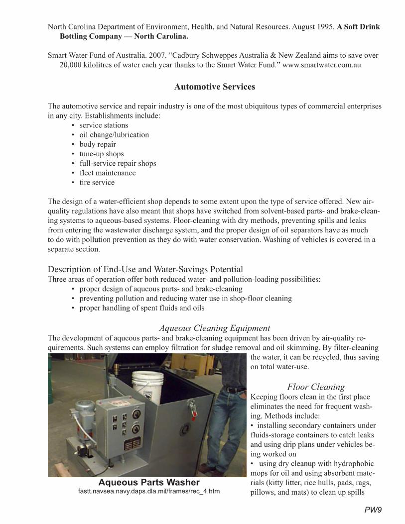
PW9
North Carolina Department of Environment, Health, and Natural Resources. August 1995. A Soft Drink Bottling Company — North Carolina.
Smart Water Fund of Australia. 2007. “Cadbury Schweppes Australia & New Zealand aims to save over 20,000 kilolitres of water each year thanks to the Smart Water Fund.” www.smartwater.com.au.
Automotive Services
The automotive service and repair industry is one of the most ubiquitous types of commercial enterprises in any city. Establishments include:
• service stations• oil change/lubrication• body repair• tune-up shops• full-service repair shops• fleet maintenance• tire service
The design of a water-efficient shop depends to some extent upon the type of service offered. New air-quality regulations have also meant that shops have switched from solvent-based parts- and brake-clean-ing systems to aqueous-based systems. Floor-cleaning with dry methods, preventing spills and leaks from entering the wastewater discharge system, and the proper design of oil separators have as much to do with pollution prevention as they do with water conservation. Washing of vehicles is covered in a separate section.
Description of End-Use and Water-Savings PotentialThree areas of operation offer both reduced water- and pollution-loading possibilities:
• proper design of aqueous parts- and brake-cleaning• preventing pollution and reducing water use in shop-floor cleaning • proper handling of spent fluids and oils
Aqueous Cleaning Equipment The development of aqueous parts- and brake-cleaning equipment has been driven by air-quality re-quirements. Such systems can employ filtration for sludge removal and oil skimming. By filter-cleaning
the water, it can be recycled, thus saving on total water-use.
Floor Cleaning Keeping floors clean in the first place eliminates the need for frequent wash-ing. Methods include: • installing secondary containers under fluids-storage containers to catch leaks and using drip plans under vehicles be-ing worked on • using dry cleanup with hydrophobic mops for oil and using absorbent mate-rials (kitty litter, rice hulls, pads, rags, pillows, and mats) to clean up spills
Aqueous Parts Washer fastt.navsea.navy.daps.dla.mil/frames/rec_4.htm
PW10
• sealing floors with an epoxy material, which significantly aids in cleanup and prevents oils and liquids from penetrating concrete floors
• providing floor-cleaning equipment that scrubs and vacuums up its own water• eliminating the use of open hoses for cleanup and using pressure-washing equipment infre-
quently and for major cleanup events only• marking drains clearly to ensure that floor drains are clearly differentiated from storm drains
and all floor drains are connected to an oil separator
Handling of Spent Fluids Recovery and recycling of radiator flush-water both saves water and reduces pollution loading. Using storage vessels designed to hold spent antifreeze and other fluids, such as oil and transmission fluid, both eliminates the need to clean and flush these fluids down a drain and is required as part of modern pollution-control methods. Water use in facilities that recycle radiator flush-water has been shown to be less than 10 percent of water use in non-recycling facilities (San Antonio Water System).
Cost-Effectiveness Analysis A cost analysis of measures to reduce both water use and pollution from the auto-repair industry is now required in part by air-pollution and water-pollution regulations. Offsets to these costs include:
• reduced pretreatment costs• reduced cost for solvents • reduced water use
Recommendations Proven Practices for Superior Performance
• Require new facilities to provide secondary containers to catch drips, leaks, and spills from stored liquids and solvents.
• Require shop floors to be sealed to ensure easy cleanup.• Require automatic shutoff and solenoid valves on all hoses and water-using equipment, where
applicable.• Require aqueous parts- and brake-cleaning equipment to employ recirculating filtration to
minimize the need to dump water.• Require all drains to be properly identified.• Have proper facilities for the capture, storage, and recycling of spent fluids, oils, and fuels,
including antifreeze and radiator flush-water.Additional Practices That Achieve Significant Savings
• Have pressure-washing equipment available. • Have drip pans available at work stations to place under vehicles.
ReferencesAqueous parts washer. fastt.navsea.navy.daps.dla.mil/frames/rec_4.htm. FASTT Director Charles E.
Tittle, [email protected], DSN 326, (202)781-1833, ext. 230.
California Department of Toxic Substance Control. P2 Opportunities Checklist for Vehicle Mainte-nance Activities.
San Antonio Water System. June 1998. Water Saver Awards.
U.S. Environmental Protection Agency. Region 9. Auto Repair and Fleet Maintenance Pollution Pre-vention. www.epa.gov/region09/waste/p2/autofleet/factauto.html.
PW11
U.S. Navy. Navy Water Conservation Guide for Shore Facilities. portal.navfac.navy.mil/pls/portal/docs/PAGE/NAVFAC/NAVFAC_WW_PP/NAVFAC_NFESC_PP/ENVIRONMENTAL/EQIFS/WASTEWATER/08_WASTEWATER/lowflow.pdf
Printing and Paper Manufacturing
Description of End UseAt first glance, printing and paper manufacturing appear to be very different industries, but according to classification by the U.S. Census and the NAICS — North American Industrial Classification System — paper manufacturing ranges from making paper from trees to manufacturing converted paper prod-ucts, such as paper containers, cups, boxes, bags, coated paper, envelopes, and stationery products. The focus of this discussion is the manufacturing of converted paper products and printing.
Producing paper from pulpwood and other fiber sources is the beginning process for all paper. It is also the most water- and energy-intensive stage in the life of a paper product. Five gallons of water are used to make one pound of paper (Weyerhaeuser). Recycling paper and cardboard products cuts this energy and water use in half (Kinsella). According to Conservatree, an organization that promotes paper re-cycling, most repulping for recycled paper is done at pulp and paper mills, where paper is made, or in special facilities that use the product to make such things as cellulose insulation or pulp products, such as egg cartons.
At these pulp and paper mills, a mixture of virgin and recycled pulp is rapidly becoming the most com-mon source of paper and cardboard stock for commercial converted products. The majority of these products will be used for printing, ranging from stationery letterheads to paper bags and boxes (Califor-nia EPA). Examples of finished products include:
• molded pulp products• cardboard tubes• roofing paper• corrugated boxes• paper bags• tissue and toweling• folded boxes• cellulose padding• stationery and envelopes• paper cups and liquid containers
Operations to make these products do not involve the direct production of pulp, but do involve the processing of paper made from these products. The production of products from paper, cardboard stock, or dry pulp represents the types of operations found in most cities. Major operations most commonly involve:
• cutting and folding• gluing• coating• printing
Cutting and folding, along with the handling of paper stock and products, is principally a dry process. Floor cleaning should follow principles outlined in the section on Cleaning and Sanitation. The last three of these operations involve wet or solvent cleaning of some type. The advent of water-soluble paints and inks has reduced volatile-organic-compound (VOC) emissions, but the use of water as a cleaning agent
PW12
is more prevalent. The same principles used in cleaning equipment in the food and beverage processing industry apply here, with the addition of solvent cleaning, which is still used in many non-aqueous print-ing processes:
• Properly remove as much waste product as possible by pouring and storing for future use.• Scrape equipment and vessels to remove as much waste as possible.• Use dry brushes, cloths, and paper towels to remove waste.• Use wet towels or solvent-soaked towels.• Apply water or solvent only to areas to be cleaned.
Flexography, gravure, screen-printing, lithography, and digital processing are all common printing prac-tices used today. To help save water, energy, materials, and time:
• Design the layout of equipment for easy access.• Ensure that ink containers are easily sealed.• Provide non-drying aerosol sprays to keep ink fountains from drying overnight. • Ensure that presses have proper controls, such as automatic ink levelers.
Water-Savings PotentialThe practices discussed above reduce water use by decreasing the amount of cleaning required at the end of the press run. Other water-saving design practices are covered in the chapter on Photo and Film Processing under Commercial Printing. Printing operations also produce large amounts of waste heat in cooling the equipment. Large operations often have cooling towers. In these cases, water-saving tech-niques outlined in the section on Thermodynamic Processes should be referenced.
Cost-Effectiveness Analysis Each case is unique, and overall cost analysis is not possible. However, the water-saving techniques outlined above will reduce operational costs by:
• reducing water and wastewater bills• reducing pretreatment costs• reducing product loss• reducing chemical use • eliminating waste
RecommendationsManufacturing of Recycled-paper Products
• Properly remove as much waste product as possible by pouring and storing for future use.• Scrape equipment and vessels to remove as much waste as possible.
Printing Operations • Design the layout of the equipment to provide easy access.• Provide non-drying aerosol sprays to keep ink fountains from drying overnight. • Ensure the press has proper controls, such as automatic ink levelers.
See “Photo and Film Processing — Commercial Printing” for additional recommendations.
ReferencesAlameda County Waste Management Authority and Recycling Board. www.stopwaste.org.
California Environmental Protection Agency. California paper, Paperboard and Pulp Mills That Consume Postconsumer Paper. www.ciwmb.ca.gov/Paper/Markets/.
PW13
City of San Jose, California. Environmental Services Department. Best Management Practices to Re-duce Pollution for Printing and Photo processing Operations.
Conservatree. Recycled and Environmental Paper Information. San Francisco, California. www.conservatree.com/.
Eco-Efficiency Centre, The. Dalhousie University. 2006. Fact Sheet: Eco-Efficiency in the Printing Industry. Dartmouth, Nova Scotia.
Kinsella, Susan. Fact Sheet: Buy Recycled Paper! Buy Recycled Business Alliance of the National Recycling Coalition.
Weyerhaeuser. 2004. 2004 Roadmap for Sustainability. www.weyerhaeuser.com/environment/sustainability/2004.
Metal FinishingThe metal-finishing industry offers many opportunities to reduce both water-use and pollution-abate-ment costs. The plating and anodizing processes involve a multi-tank, multi-step process. Water-saving practices include:
• drag-out control• good tank design• efficient rinse practices• process controls and meters• chemical recovery• good exhaust-hood design
As with all industrial and commercial operations, efficient cleaning methods are key practices that will result in reduced water use.
Description of End UseThe classic example for the metal-finishing industry was once the plating of car bumpers (when chrome car bumpers were still manufactured). The industry involves much more than that today. For metals, it includes electroplating, solution plating, and anodizing, but also printed circuit (wire) board and plastic plating. Chrome, zinc, copper, tin, nickel, gold, and silver are among the more common metals plated onto objects. In some processes objects are plated with two layers of metals, such as an under layer of copper followed by chrome.
One common process in this industry is that parts to be plated are moved sequentially from a treatment tank to a rinse or wash tank to another treatment tank to another rinse tank, until the desired number of plating steps have been accomplished. The photograph from the Corpus Christi, Texas, Army Depot, which follows, illustrates the multi-tank configuration of a typical metal-finishing process.
Water is used for the following process purposes:• chemical and plating solution make-up• rinsing• fume-hood scrubbing• equipment cleaning
The typical sequence for plating an object is:
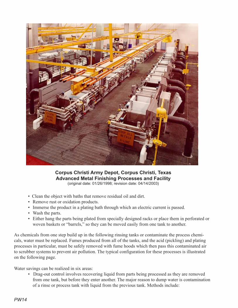
PW14
• Clean the object with baths that remove residual oil and dirt.• Remove rust or oxidation products.• Immerse the product in a plating bath through which an electric current is passed. • Wash the parts.• Either hang the parts being plated from specially designed racks or place them in perforated or
woven baskets or “barrels,” so they can be moved easily from one tank to another.
As chemicals from one step build up in the following rinsing tanks or contaminate the process chemi-cals, water must be replaced. Fumes produced from all of the tanks, and the acid (pickling) and plating processes in particular, must be safely removed with fume hoods which then pass this contaminated air to scrubber systems to prevent air pollution. The typical configuration for these processes is illustrated on the following page.
Water savings can be realized in six areas: • Drag-out control involves recovering liquid from parts being processed as they are removed
from one tank, but before they enter another. The major reason to dump water is contamination of a rinse or process tank with liquid from the previous tank. Methods include:
Corpus Christi Army Depot, Corpus Christi, Texas Advanced Metal Finishing Processes and Facility
(original date: 01/26/1998; revision date: 04/14/2003)
PW1�
designing racks, baskets, and barrels so parts drain and do not retain liquids using turning, tilting, and “bumping” to remove excess liquidusing drip or drain boards to collect and drain liquids back into the source tankallowing parts to remain over the tank for a few seconds (dwell time)washing or blowing contaminants back into process or dead tanks using fogs, sprays, or air knives using wetting agentsusing chemicals or heat to reduce plating-solution viscosity operating the solutions at minimum possible concentration
• The following tank-design methods reduce water use or allow for better reuse and recovery of metals:
using air or mechanical agitation to promote mixing and good contacthard plumbing all piping so hoses cannot be left on inadvertently preventing short-circuiting of fluids sizing tanks to the minimum for the pieces to be plated segregating waste streams so both metals and water can be recovered more easily
• Efficient rinsing saves water and chemicals and reduces wastewater costs. Methods involve several technologies, including:
using sprays on flat pieces of metalcounter-current rinsing, where the piece is rinsed in successively less concentrated tanks, with the water from the first tank being used as feed for the second, and so on reactive rinsing, where the rinse water from the final tank is used for the pickle-rinse tank and the pickle-rinse tank water is used as feed to make up the alkaline-rinse tank (see figure following)air agitation of the tanks
• Flow- and process-control opportunities include:installing conductivity controllers to discharge water only if the chemicals have become too concentratedmetering makeup water for good process control and to identify problemsusing flow restrictors to limit the amount of water being added
• Chemical and water recovery includes several water-treatment technologies:filtering plating fluid to remove suspended matterusing membrane technology to recover metals and waterusing RO or deionization for the feed water for both rinse and process-fluid tanks to re-duce interference from other ionsregenerating spent acidsusing RO-reject water for cleanup around, but not in, the tanks
• Exhaust-hood design can also reduce water use by:Recirculating scrubber liquidUsing scrubber water above plating tanks as make-up water for that processUsing RO-reject water or similar reject streams as make-up water for scrubbers for which scrubber effluent will not be reused
Water-Savings Potential and Cost-Saving ExamplesFollowing are examples from real operations of water-saving projects, their costs, and their savings. Be-cause of the varied nature of this sector, each case must be examined separately, but the basic techniques have proven effective to:
• reduce water and wastewater costs• reduce pretreatment costs• reduce energy costs
»»»»»
»»»
»»»»»
»»
»
»
»
»»
»»»
»»
»»»
PW16
• reduce chemical cost• increase chemical and metals recovery rates• reduce labor costs
Because of the wide variation in process design and operations, a simple cost analysis is not possible. Instead, the following examples are provided:
• Example 1 — A small plating shop in Australia that was using 360 gallons of water a day installed drain boards and a deionizer for $590. The cost for servicing the deionizer is ap-proximately $780 per year. These measures cut water use by 65,000 gallons a year and saved over $1,600 in chemical cost each year for a pay back of 1.3 years (Environmental Protection Agency of Victoria, Australia). [Based upon current U.S. dollars adjusted for inflation and cur-rency conversion rate.]
• Example 2 — A large industrial operation in Illinois installed conductivity controllers on two tanks, reducing water use in the first tank from 5.0 to 0.45 gpm and in a second tank from 2.0 to 0.5 gpm. The total installed cost for the conductivity controllers and valves was $2,000. This saved over 3 million gallons of water a year (Brown).
• Example 3 — A Minnesota manufacturer installed conductivity controllers for $2,100 and reduced water use by one million gallons a year (Minnesota Technical Assistance Program).
Recommendations Proven Practices for Superior Performance
• Meter make-up water in new facilities.• Employ counter-current rinsing.• Control drag-out by applying at least two of the practices listed above.• Use conductivity controllers for rinse tanks.• Install automatic shutoff on all hoses.• Recirculate water and/or use waste streams as makeup water for scrubbers.
Additional Practices That Achieve Significant Savings• Employ good tank design.• Mix or use air agitation of tank contents.• Us multiple drag-out reduction methods.• Install filtration and water-treatment equipment, where applicable.• Use reactive rinsing.
ReferencesBrown, Jerry. 2000. Pollution Prevention Case Study – Conductivity Controller Technology. TN -72.
Chicago, Illinois.
CH2MHill. May 2002. Air Force Water Conservation Guidebook.
De Deitrich. Electroplating Rinse Practices and Evaporator Sizing. www.ddpsic.com.
Department of Planning and Environmental Protection. Broward County, Florida. October 2003. Pollu-tion Prevention and Best Management Practices for Metal Finishing Facilities. Fort Lauderdale, Florida.
Donovan, Robert P., Morrison, Dennis J., and Timon, Robert P. November 1998. Design of Recycling Systems for Spent Rinse Water in Sandia’s Microelectronics Development Laboratory. Interna-tional SEMATECH TT# 98113599A-ENG.
PW17
Environmental Protection Agency of Victoria, Australia. 1993. Waste Minimization—Assessment and Opportunities for Industry. Southbank, Victoria. ISBN 07306-2888-4.
Minnesota Technical Assistance Program. 1997. Hoffman Engineering Saves $32,000 Annually by Reducing Water Use. www.mntap.umn.edu/intem/projects.
Narragansett Bay Commission, The. P2 Facts: Industrial Rinse Water Reduction. Providence, Rhode Island.
National Center for Manufacturing Science. 2007. Printed Wire Board. Printed Wire Board Resource Center. Ann Arbor, Michigan. Metal Products and Machinery (MP&M) PWB Subcategory. www.pwbrc.org/mpmpwb.cfm.
New Mexico. Office of State Engineer. July 1999. A Water Conservation Guide for Commercial, Institutional and Industrial Water Users.
North Carolina. Department of Environment and Natural Resources. Division of Pollution Prevention. August 1998. Water Efficiency Manual for Commercial, Industrial, and Institutional Facilities.
Ogunbameru, Gus, Ph.C., Ch.E. 2004. Best Management Practices for Selected Industries and Ad-ditional Resources. Massachusetts Office of Technical Assistance.
Rosemont Analytical Inc. 2003. Water Conservation in Metal Finishing. Emerson Process Manage-ment. Irvine, California.
Thompson, Chris, and Lickteig, Edward. October 2008. Recycling High Purity Rinsewater at Sam-sung Austin Semiconductor. Samsung Austin Semiconductor. Ultrapure Water. Austin, Texas.

PW18
This page intentionally left blank
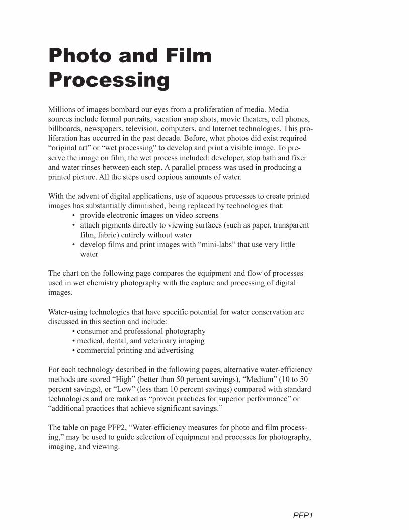
PFP1
Millions of images bombard our eyes from a proliferation of media. Media sources include formal portraits, vacation snap shots, movie theaters, cell phones, billboards, newspapers, television, computers, and Internet technologies. This pro-liferation has occurred in the past decade. Before, what photos did exist required “original art” or “wet processing” to develop and print a visible image. To pre-serve the image on film, the wet process included: developer, stop bath and fixer and water rinses between each step. A parallel process was used in producing a printed picture. All the steps used copious amounts of water.
With the advent of digital applications, use of aqueous processes to create printed images has substantially diminished, being replaced by technologies that:
• provide electronic images on video screens • attach pigments directly to viewing surfaces (such as paper, transparent
film, fabric) entirely without water• develop films and print images with “mini-labs” that use very little
water
The chart on the following page compares the equipment and flow of processes used in wet chemistry photography with the capture and processing of digital images.
Water-using technologies that have specific potential for water conservation are discussed in this section and include:
• consumer and professional photography • medical, dental, and veterinary imaging• commercial printing and advertising
For each technology described in the following pages, alternative water-efficiency methods are scored “High” (better than 50 percent savings), “Medium” (10 to 50 percent savings), or “Low” (less than 10 percent savings) compared with standard technologies and are ranked as “proven practices for superior performance” or “additional practices that achieve significant savings.”
The table on page PFP2, “Water-efficiency measures for photo and film process-ing,” may be used to guide selection of equipment and processes for photography, imaging, and viewing.
Photo and Film Processing
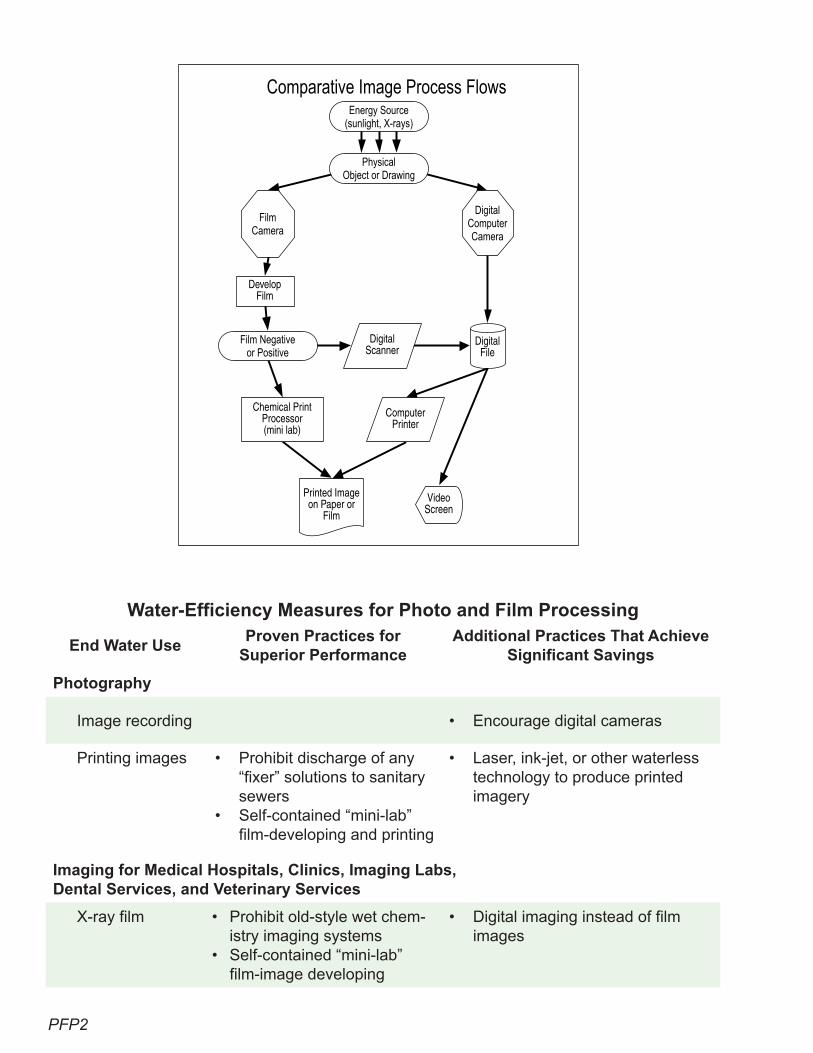
PFP2
Water-Efficiency Measures for Photo and Film Processing
End Water UseProven Practices for
Superior PerformanceAdditional Practices That Achieve
Significant Savings
Photography
Image recording • Encourage digital cameras
Printing images • Prohibit discharge of any “fixer” solutions to sanitary sewers
• Self-contained “mini-lab” film-developing and printing
• Laser, ink-jet, or other waterless technology to produce printed imagery
Imaging for Medical Hospitals, Clinics, Imaging Labs, Dental Services, and Veterinary Services
X-ray film • Prohibit old-style wet chem-istry imaging systems
• Self-contained “mini-lab” film-image developing
• Digital imaging instead of film images
Comparative Image Process FlowsEnergy Source
(sunlight, X-rays)
PhysicalObject or Drawing
FilmCamera
DigitalComputerCamera
DigitalFile
VideoScreen
ComputerPrinter
Film Negativeor Positive
DevelopFilm
DigitalScanner
Chemical PrintProcessor(mini lab)
Printed Image on Paper or
Film
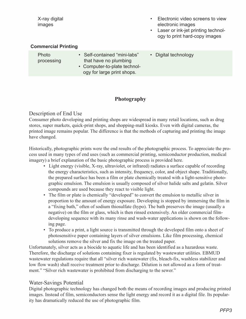
PFP3
X-ray digital images
• Electronic video screens to view electronic images
• Laser or ink-jet printing technol-ogy to print hard-copy images
Commercial Printing
Photo processing
• Self-contained “mini-labs” that have no plumbing
• Computer-to-plate technol-ogy for large print shops.
• Digital technology
Photography
Description of End UseConsumer photo developing and printing shops are widespread in many retail locations, such as drug stores, super markets, quick-print shops, and shopping-mall kiosks. Even with digital cameras, the printed image remains popular. The difference is that the methods of capturing and printing the image have changed.
Historically, photographic prints were the end results of the photographic process. To appreciate the pro-cess used in many types of end uses (such as commercial printing, semiconductor production, medical imagery) a brief explanation of the basic photographic process is provided here.
• Light energy (visible, X-ray, ultraviolet, or infrared) radiates a surface capable of recording the energy characteristics, such as intensity, frequency, color, and object shape. Traditionally, the prepared surface has been a film or plate chemically treated with a light-sensitive photo-graphic emulsion. The emulsion is usually composed of silver halide salts and gelatin. Silver compounds are used because they react to visible light.
• The film or plate is chemically “developed” to convert the emulsion to metallic silver in proportion to the amount of energy exposure. Developing is stopped by immersing the film in a “fixing bath,” often of sodium thiosulfate (hypo). The bath preserves the image (usually a negative) on the film or glass, which is then rinsed extensively. An older commercial film- developing sequence with its many rinse and wash-water applications is shown on the follow-ing page.
• To produce a print, a light source is transmitted through the developed film onto a sheet of photosensitive paper containing layers of silver emulsions. Like film processing, chemical solutions remove the silver and fix the image on the treated paper.
Unfortunately, silver acts as a biocide to aquatic life and has been identified as a hazardous waste. Therefore, the discharge of solutions containing fixer is regulated by wastewater utilities. EBMUD wastewater regulations require that all “silver rich wastewater (fix, bleach-fix, washless stabilizer and low flow wash) shall receive treatment prior to discharge. Dilution is not allowed as a form of treat-ment.” “Silver rich wastewater is prohibited from discharging to the sewer.”
Water-Savings Potential Digital photographic technology has changed both the means of recording images and producing printed images. Instead of film, semiconductors sense the light energy and record it as a digital file. Its popular-ity has dramatically reduced the use of photographic film.
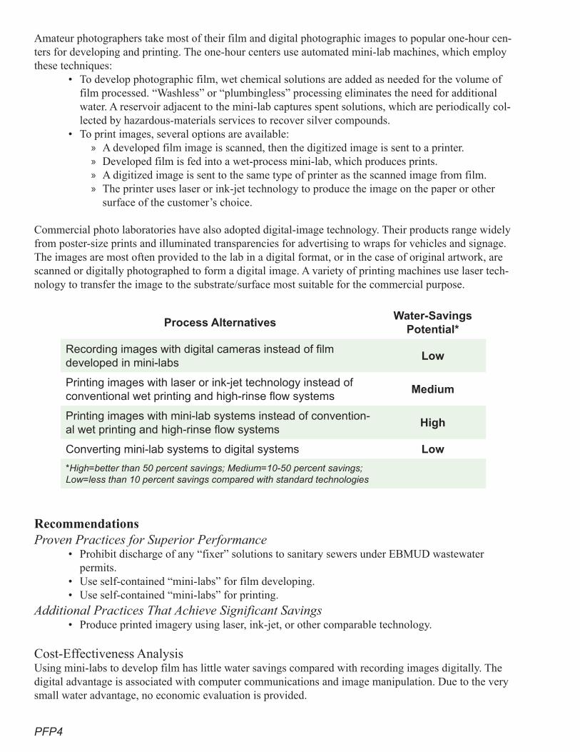
PFP4
Amateur photographers take most of their film and digital photographic images to popular one-hour cen-ters for developing and printing. The one-hour centers use automated mini-lab machines, which employ these techniques:
• To develop photographic film, wet chemical solutions are added as needed for the volume of film processed. “Washless” or “plumbingless” processing eliminates the need for additional water. A reservoir adjacent to the mini-lab captures spent solutions, which are periodically col-lected by hazardous-materials services to recover silver compounds.
• To print images, several options are available: A developed film image is scanned, then the digitized image is sent to a printer. Developed film is fed into a wet-process mini-lab, which produces prints.A digitized image is sent to the same type of printer as the scanned image from film. The printer uses laser or ink-jet technology to produce the image on the paper or other surface of the customer’s choice.
Commercial photo laboratories have also adopted digital-image technology. Their products range widely from poster-size prints and illuminated transparencies for advertising to wraps for vehicles and signage. The images are most often provided to the lab in a digital format, or in the case of original artwork, are scanned or digitally photographed to form a digital image. A variety of printing machines use laser tech-nology to transfer the image to the substrate/surface most suitable for the commercial purpose.
Process Alternatives Water-Savings
Potential*
Recording images with digital cameras instead of film developed in mini-labs
Low
Printing images with laser or ink-jet technology instead of conventional wet printing and high-rinse flow systems
Medium
Printing images with mini-lab systems instead of convention-al wet printing and high-rinse flow systems
High
Converting mini-lab systems to digital systems Low
*High=better than �0 percent savings; Medium=10-�0 percent savings; Low=less than 10 percent savings compared with standard technologies
RecommendationsProven Practices for Superior Performance
• Prohibit discharge of any “fixer” solutions to sanitary sewers under EBMUD wastewater permits.
• Use self-contained “mini-labs” for film developing.• Use self-contained “mini-labs” for printing.
Additional Practices That Achieve Significant Savings• Produce printed imagery using laser, ink-jet, or other comparable technology.
Cost-Effectiveness AnalysisUsing mini-labs to develop film has little water savings compared with recording images digitally. The digital advantage is associated with computer communications and image manipulation. Due to the very small water advantage, no economic evaluation is provided.
»»»»
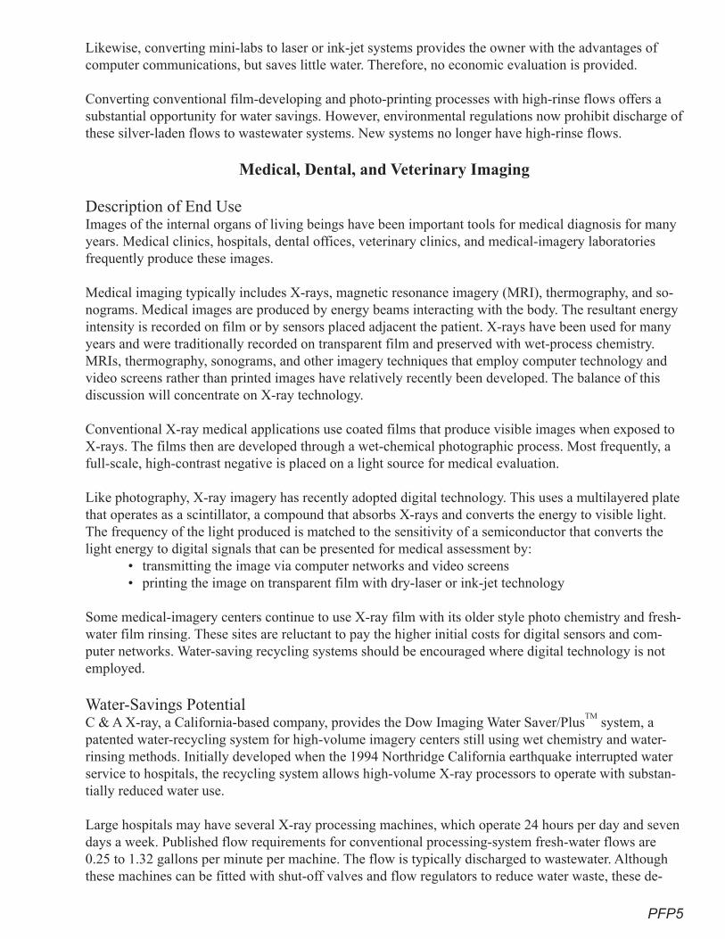
PFP�
Likewise, converting mini-labs to laser or ink-jet systems provides the owner with the advantages of computer communications, but saves little water. Therefore, no economic evaluation is provided.
Converting conventional film-developing and photo-printing processes with high-rinse flows offers a substantial opportunity for water savings. However, environmental regulations now prohibit discharge of these silver-laden flows to wastewater systems. New systems no longer have high-rinse flows.
Medical, Dental, and Veterinary Imaging
Description of End UseImages of the internal organs of living beings have been important tools for medical diagnosis for many years. Medical clinics, hospitals, dental offices, veterinary clinics, and medical-imagery laboratories frequently produce these images.
Medical imaging typically includes X-rays, magnetic resonance imagery (MRI), thermography, and so-nograms. Medical images are produced by energy beams interacting with the body. The resultant energy intensity is recorded on film or by sensors placed adjacent the patient. X-rays have been used for many years and were traditionally recorded on transparent film and preserved with wet-process chemistry. MRIs, thermography, sonograms, and other imagery techniques that employ computer technology and video screens rather than printed images have relatively recently been developed. The balance of this discussion will concentrate on X-ray technology.
Conventional X-ray medical applications use coated films that produce visible images when exposed to X-rays. The films then are developed through a wet-chemical photographic process. Most frequently, a full-scale, high-contrast negative is placed on a light source for medical evaluation.
Like photography, X-ray imagery has recently adopted digital technology. This uses a multilayered plate that operates as a scintillator, a compound that absorbs X-rays and converts the energy to visible light. The frequency of the light produced is matched to the sensitivity of a semiconductor that converts the light energy to digital signals that can be presented for medical assessment by:
• transmitting the image via computer networks and video screens• printing the image on transparent film with dry-laser or ink-jet technology
Some medical-imagery centers continue to use X-ray film with its older style photo chemistry and fresh-water film rinsing. These sites are reluctant to pay the higher initial costs for digital sensors and com-puter networks. Water-saving recycling systems should be encouraged where digital technology is not employed.
Water-Savings Potential C & A X-ray, a California-based company, provides the Dow Imaging Water Saver/Plus
TM system, a
patented water-recycling system for high-volume imagery centers still using wet chemistry and water-rinsing methods. Initially developed when the 1994 Northridge California earthquake interrupted water service to hospitals, the recycling system allows high-volume X-ray processors to operate with substan-tially reduced water use.
Large hospitals may have several X-ray processing machines, which operate 24 hours per day and seven days a week. Published flow requirements for conventional processing-system fresh-water flows are 0.25 to 1.32 gallons per minute per machine. The flow is typically discharged to wastewater. Although these machines can be fitted with shut-off valves and flow regulators to reduce water waste, these de-
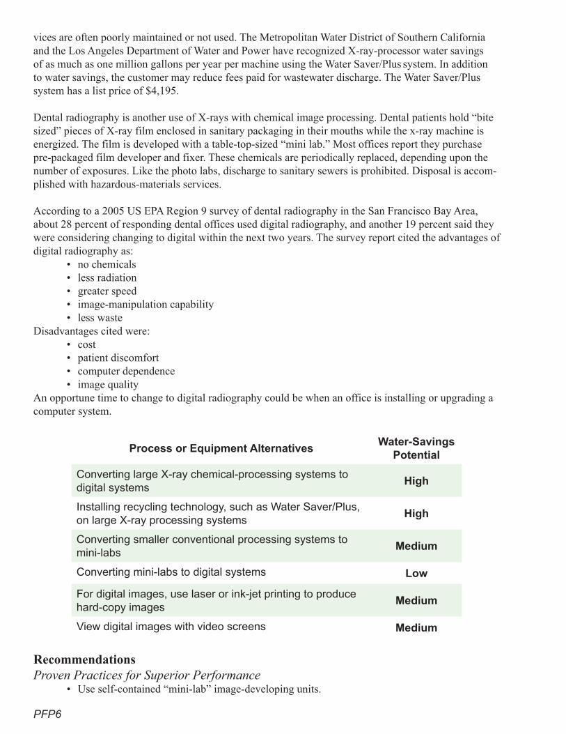
PFP6
vices are often poorly maintained or not used. The Metropolitan Water District of Southern California and the Los Angeles Department of Water and Power have recognized X-ray-processor water savings of as much as one million gallons per year per machine using the Water Saver/Plus system. In addition to water savings, the customer may reduce fees paid for wastewater discharge. The Water Saver/Plus
system has a list price of $4,195.
Dental radiography is another use of X-rays with chemical image processing. Dental patients hold “bite sized” pieces of X-ray film enclosed in sanitary packaging in their mouths while the x-ray machine is energized. The film is developed with a table-top-sized “mini lab.” Most offices report they purchase pre-packaged film developer and fixer. These chemicals are periodically replaced, depending upon the number of exposures. Like the photo labs, discharge to sanitary sewers is prohibited. Disposal is accom-plished with hazardous-materials services.
According to a 2005 US EPA Region 9 survey of dental radiography in the San Francisco Bay Area, about 28 percent of responding dental offices used digital radiography, and another 19 percent said they were considering changing to digital within the next two years. The survey report cited the advantages of digital radiography as:
• no chemicals• less radiation• greater speed• image-manipulation capability• less waste
Disadvantages cited were:• cost• patient discomfort• computer dependence• image quality
An opportune time to change to digital radiography could be when an office is installing or upgrading a computer system.
Process or Equipment AlternativesWater-Savings
Potential
Converting large X-ray chemical-processing systems to digital systems
High
Installing recycling technology, such as Water Saver/Plus,
on large X-ray processing systemsHigh
Converting smaller conventional processing systems to mini-labs
Medium
Converting mini-labs to digital systems Low
For digital images, use laser or ink-jet printing to produce hard-copy images
Medium
View digital images with video screens Medium
RecommendationsProven Practices for Superior Performance
• Use self-contained “mini-lab” image-developing units.
PFP7
Additional Practices That Achieve Significant Savings • Produce images using laser or ink-jet printing technology.• View images on electronic video screens.
Cost-Effectiveness AnalysisConversion of mini-labs to digital systems provides the owner with advantages associated with computer communications, but saves little water. Due to the very small water advantage, no economic evaluation is provided.
Commercial Printing
Description of End UseCommercial printing is a major business. Printing establishments include photocopy shops, offset print-ers, large newspapers, and book publishers. All of them potentially use photographic techniques.
The main technologies of commercial printing are flexography, gravure, screen-printing, lithography, and digital processing. All of them use three major steps: prepress, press (e.g., putting ink on paper), and post-press (e.g., binding). The following discussion focuses on prepress elements, because they use photographic processes.
Historic prepress operations focus on composition: the arrangement of art, photos, and text into the desired format. Once the format and images are assembled, they are photographed. The photographed negative or positive images are next transferred to an image carrier used to produce a plate, cylinder, or screen that has been treated with a light-sensitive coating. Light is transmitted through the negative or positive film to expose the coated plate. The exposed plate is then processed to produce a plate with defined printing and non-printing areas. During processing, the soluble areas of the coating are washed away, while the insoluble areas remain on the plate. The insoluble areas of coating remaining on the plate become the ink carriers during printing.
Water-Savings Potential The advent of desktop publishing made it possible for text and images to be manipulated easily on per-sonal computers for eventual printing on desktop or commercial presses. The development of digital im-age-setters enabled print shops to produce negatives for platemaking directly from digital input, skipping the intermediate step of photographing an actual page layout. The development of the digital platesetter (a machine that makes the plate ready for the press) in the late twentieth century eliminated film nega-tives altogether by exposing printing plates directly from digital input, a process known as “computer-to-plate” (CtP) printing.
Process or Equipment Alternative Water-Savings Potential
For non-digital photographic printing require self-contained mini-labs instead of high-water-use processing
High
Convert from a wet-photo process to CtP technology
Medium
In addition to reducing production time and improving plate quality, CtP eliminates the chemical image-development process and the accompanying water use. During the past decade, this has been a quickly changing technology.
PFP8
RecommendationsProven Practices for Superior Performance
• For photo processing, use self-contained “mini lab” units that require no plumbing or washing.• Employ CtP technology in large print shops.
Additional Practices That Achieve Significant Savings• Adopt CtP technology.
Cost-Effectiveness AnalysisConversion from conventional plate creation to CtP has several benefits that may be more valuable than the cost of water. The industry cites these benefits to include:
• eliminating the cost of the processor, including floor space • eliminating the cost of chemistry • eliminating processor maintenance • reducing inventory costs • eliminating the oven, with its associated energy costs, for baking the plates • reduced waste disposal • improved environmental compliance
The transformation to computer equipment and CtP technology has considerable initial cost. In the long run, the capital cost is outweighed by the improvements and their accompanying benefits.
ReferencesU.S. Environmental Protection Agency. Illinois Waste Management & Research R5. Contact Deb Jacob-
son, 630-472-5019.
U.S. Environmental Protection Agency. 1995. Office of Compliance Project. Profile of the Printing Industry. Publication #: EPA/310-R-95-014 SIC Code: 27.
Varian Medical Systems, www.varian.com/xray/prd003b.html
“Plates process free.” February 2005. Graphic Arts Monthly. www.gammag.com/Current/index.php?art=gam0502Fplateprocfree
“Processor-free CTP.” March 1, 2006. American Printer. americanprinter.com/mag/process_free_ctp_0306/
“What is CTP?” Webopedia. www.webopedia.com/TERM/C/computer_to_plate.html
Digital Data Delivery for Australian Publications. www.3dap.com.au/whatisctp.htm
MFL1
Dental and doctors’ offices can be very-low water-use facilities if the correct equipment is used. Large general hospitals are much more of a challenge, since many processes in these facilities use water. Hospital water use ranges from 250 to 800 gallons per bed (Marutore). There is significant opportunity in this industry to design more water-efficient facilities. Laboratories present a further opportunity for water efficiency.
This section examines the following types of facilities:• clinics• hospitals• dental offices• medical laboratories• veterinary hospitals and clinics• research and analytical laboratories • industrial and commercial laboratories• operations using similar equipment
Medical facilities and laboratories have certain water uses in common with other businesses. These include normal office uses and, in the case of hospitals, opera-tions that closely resemble those of a hotel, with its food-service, laundry, boiler, fire-plumbing systems, air-conditioning, and cooling-tower operations. Beyond that, medical facilities and laboratories have a number of unique water-using activities, including:
• vacuum systems• medical air and compressor equipment• sterilizers and central sterile operations• water-cooled laboratory and therapeutic equipment• laboratory hood scrubbers• X-ray equipment and film developers• water-treatment systems for kidney dialysis and laboratory water
• therapeutic baths and treatments
This section examines the first five of these technologies in detail. Water-savings potential for X-ray equipment is significant and is covered in the section, “Photo and Film Processing.” Water-conservation techniques for water-treatment equip-ment are described in the section, “Water Treatment.”
Description of End UseVacuum systems are used to remove liquid waste or produce a vacuum to main-tain low pressure or evacuate a vessel. These range from the suction devices used by dentists and surgeons to remove body fluids to large surgical-unit vacuum pumps that remove gases used for anesthesia. Most major medical facilities also
Medical Facilities and Laboratories
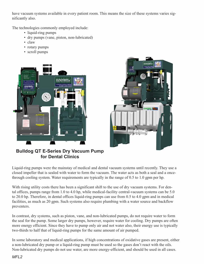
MFL2
have vacuum systems available in every patient room. This means the size of these systems varies sig-nificantly also.
The technologies commonly employed include:• liquid-ring pumps• dry pumps (vane, piston, non-lubricated)• claw• rotary pumps• scroll pumps
Liquid-ring pumps were the mainstay of medical and dental vacuum systems until recently. They use a closed impeller that is sealed with water to form the vacuum. The water acts as both a seal and a once-through cooling system. Water requirements are typically in the range of 0.5 to 1.0 gpm per hp.
With rising utility costs there has been a significant shift to the use of dry vacuum systems. For den-tal offices, pumps range from 1.0 to 4.0 hp, while medical-facility central-vacuum systems can be 5.0 to 20.0 hp. Therefore, in dental offices liquid-ring pumps can use from 0.5 to 4.0 gpm and in medical facilities, as much as 20 gpm. Such systems also require plumbing with a water source and backflow preventers.
In contrast, dry systems, such as piston, vane, and non-lubricated pumps, do not require water to form the seal for the pump. Some larger dry pumps, however, require water for cooling. Dry pumps are often more energy efficient. Since they have to pump only air and not water also, their energy use is typically two-thirds to half that of liquid-ring pumps for the same amount of air pumped.
In some laboratory and medical applications, if high concentrations of oxidative gases are present, either a non-lubricated dry pump or a liquid-ring pump must be used so the gases don’t react with the oils. Non-lubricated dry pumps do not use water, are more energy-efficient, and should be used in all cases.
Bulldog QT E-Series Dry Vacuum Pump for Dental Clinics
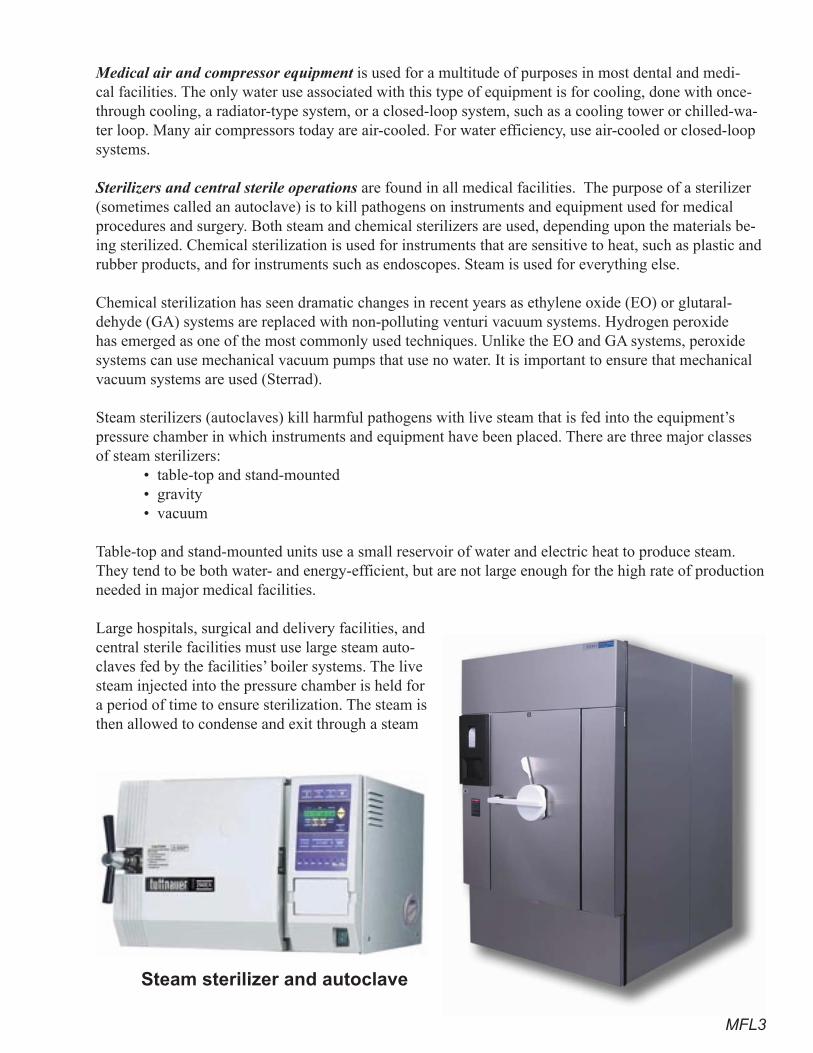
MFL3
Medical air and compressor equipment is used for a multitude of purposes in most dental and medi-cal facilities. The only water use associated with this type of equipment is for cooling, done with once-through cooling, a radiator-type system, or a closed-loop system, such as a cooling tower or chilled-wa-ter loop. Many air compressors today are air-cooled. For water efficiency, use air-cooled or closed-loop systems.
Sterilizers and central sterile operations are found in all medical facilities. The purpose of a sterilizer (sometimes called an autoclave) is to kill pathogens on instruments and equipment used for medical procedures and surgery. Both steam and chemical sterilizers are used, depending upon the materials be-ing sterilized. Chemical sterilization is used for instruments that are sensitive to heat, such as plastic and rubber products, and for instruments such as endoscopes. Steam is used for everything else.
Chemical sterilization has seen dramatic changes in recent years as ethylene oxide (EO) or glutaral-dehyde (GA) systems are replaced with non-polluting venturi vacuum systems. Hydrogen peroxide has emerged as one of the most commonly used techniques. Unlike the EO and GA systems, peroxide systems can use mechanical vacuum pumps that use no water. It is important to ensure that mechanical vacuum systems are used (Sterrad).
Steam sterilizers (autoclaves) kill harmful pathogens with live steam that is fed into the equipment’s pressure chamber in which instruments and equipment have been placed. There are three major classes of steam sterilizers:
• table-top and stand-mounted• gravity• vacuum
Table-top and stand-mounted units use a small reservoir of water and electric heat to produce steam. They tend to be both water- and energy-efficient, but are not large enough for the high rate of production needed in major medical facilities.
Large hospitals, surgical and delivery facilities, and central sterile facilities must use large steam auto-claves fed by the facilities’ boiler systems. The live steam injected into the pressure chamber is held for a period of time to ensure sterilization. The steam is then allowed to condense and exit through a steam
Steam sterilizer and autoclave
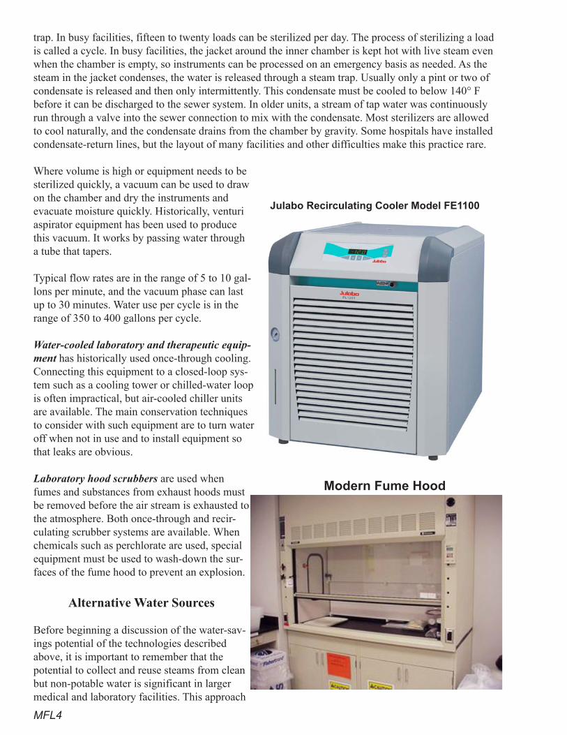
MFL4
trap. In busy facilities, fifteen to twenty loads can be sterilized per day. The process of sterilizing a load is called a cycle. In busy facilities, the jacket around the inner chamber is kept hot with live steam even when the chamber is empty, so instruments can be processed on an emergency basis as needed. As the steam in the jacket condenses, the water is released through a steam trap. Usually only a pint or two of condensate is released and then only intermittently. This condensate must be cooled to below 140° F before it can be discharged to the sewer system. In older units, a stream of tap water was continuously run through a valve into the sewer connection to mix with the condensate. Most sterilizers are allowed to cool naturally, and the condensate drains from the chamber by gravity. Some hospitals have installed condensate-return lines, but the layout of many facilities and other difficulties make this practice rare.
Where volume is high or equipment needs to be sterilized quickly, a vacuum can be used to draw on the chamber and dry the instruments and evacuate moisture quickly. Historically, venturi aspirator equipment has been used to produce this vacuum. It works by passing water through a tube that tapers.
Typical flow rates are in the range of 5 to 10 gal-lons per minute, and the vacuum phase can last up to 30 minutes. Water use per cycle is in the range of 350 to 400 gallons per cycle.
Water-cooled laboratory and therapeutic equip-ment has historically used once-through cooling. Connecting this equipment to a closed-loop sys-tem such as a cooling tower or chilled-water loop is often impractical, but air-cooled chiller units are available. The main conservation techniques to consider with such equipment are to turn water off when not in use and to install equipment so that leaks are obvious.
Laboratory hood scrubbers are used when fumes and substances from exhaust hoods must be removed before the air stream is exhausted to the atmosphere. Both once-through and recir-culating scrubber systems are available. When chemicals such as perchlorate are used, special equipment must be used to wash-down the sur-faces of the fume hood to prevent an explosion.
Alternative Water Sources
Before beginning a discussion of the water-sav-ings potential of the technologies described above, it is important to remember that the potential to collect and reuse steams from clean but non-potable water is significant in larger medical and laboratory facilities. This approach
Modern Fume Hood
Julabo Recirculating Cooler Model FE1100

MFL�
is promoted by “Labs for the 21st Century,” a joint program of the US EPA and the Department of En-ergy. Possible sources of water include:
• any once-through cooling-water discharge• water from reverse-osmosis units• foundation drain water• rain water• other appropriate sources
Using reclaimed water from municipal sources is also possible for irrigation and cooling-tower makeup, as well as toilet and urinal flushing. The following diagram is for illustrative purposes only. Such a system must be equipped with proper backflow prevention and pumps where pressurized output is needed.
Water-Savings PotentialFor the equipment described in the section above, the fol-lowing water savings are possible:
Vacuum SystemsDry systems do not use water for the pump seal but can use water for cooling the pump. Water-use rates for a liquid-ring pump range from 0.5 to 1.0 gpm per hp. Even this will be totally eliminated if no cooling water is used. Pumps should never be cooled with a once-through system. If a water-using system must be used, it should be hooked to a closed-loop or radiator-type system. The typical dental unit with a 1.5 hp liquid-ring pump can use 360 to 720 gpd (Sable Industries). For a large medical facility with a 12 hp pump, the water used per day can range from 8,640 to 17,280 gallons. Newer liquid-ring pumps try to minimize water use, so their consumption would most likely be in range of 8,600 to 10,000 gpd. Using a dry-vacuum pump will save significant volumes of water or eliminate water use (Tuthill).
Esco Fume Scrubbers
US EPA Office of Administration and Resources Management. Laboratories for the 21st Century. www.Labs21century.gov/toolkit/bp_guide.htm
Non-Potable-Water Collection and Reuse
MFL6
Medical Air and Compressor EquipmentCompressors generate significant heat as they compress the air. Smaller units, such as those used in den-tal and smaller medical facilities, can easily be air cooled. Compressors larger than 10 or 15 hp (Tuthill), however, often require water cooling. Ten hp equals 7.5 kW, and a once-through-cooled compressor that size would require a constant stream of 5 to 6 gpm to cool it when in operation. When water cooling is necessary, the compressor cooling system must be hooked to a looped cooling system. If not, water demands for this example could exceed 8,000 gpd.
Sterilizer OperationsWater use per cycle for large vacuum-steam sterilizers ranges from 350 to 400 gallons per cycle (TDK Consulting). Now new equipment often comes equipped with condensate-tempering systems (CTS). Mechanical vacuum pumps and other equipment can be retrofitted with after-purchase equipment (Con-tinental Equipment). To reduce water use per cycle to less than 80 gallons.
The use of CTS on gravity and vacuum sterilizers also reduces water use significantly. Since the typical flow rate for tempering is 0.3 to 1.0 gpm, water use can be in the range of 450 to 1,500 gpd. The installa-tion of a CTS can reduce this water use by 85 percent to 65 to 200 gpd.
Water-cooled Laboratory and Therapeutic EquipmentDaily water use depends upon the type of equipment being cooled and the length of time the equipment is used daily. Flow rates of 0.5 to 5.0 gpm are possible for each piece of equipment. Connecting larger stationary equipment to a closed-loop system is the first logical step in reducing water use to near zero. Recirculating water systems also minimize water use.
Laboratory Hood ScrubbersFlow rates in scrubbers can be high. Recirculating systems reduce this use to a few gpm when operating.
Cost-Effectiveness Analysis Vacuum Systems Because liquid-ring vacuum systems must move both air and water, they are inherently less energy ef-ficient and use significant amounts of water. However, they also tend to be the least expensive vacuum systems, based upon size and capacity (from a search of web sites for such equipment), so there is a true tradeoff between initial cost and operating cost.
A number of dry-vacuum systems are available for dental applications. The cost for a new dry-vacuum pump in the one to two hp size is $5,000 to $9,000. By comparison, a liquid-ring pump of the same hp costs $2,000 to $4,000. However, because dry systems are more efficient, a one hp dry system can often replace a 1.5 to 2.0 hp liquid-ring system. This partially offsets this cost difference. On an annual basis, dry systems use one-third to one-half less electricity than a liquid-ring pump and have zero water use (Tuthill). As an example, compare a system that requires a 1.5 hp liquid-ring pump with a 1.0 hp dry pump. In an eight hour day, the liquid-ring pump will use 540 gallons of water and 9 kWh of energy. The dry pump will use no water and only 6 kWh.
If the liquid-ring system of a large medical center requires a 23 hp pump, a comparable dry system (piston, vane, or non-lubricated) would require only 12 to 15 hp. Liquid-ring pumps require as much as twice the horsepower of equivalent dry-vacuum pumps because both water and air must be pumped. Liquid-ring pumps in continuous operation use water at a rate of 16,000 to 30,000 gpd.
In one example from a firm that sells all four kinds of pump systems, a 23 hp pump will use about 2.9 million gallons of water per year and 152,000 kWh of power (Tuthill). In contrast, the same tasks could
MFL7
be accomplished by a 12 hp vane pump, which would use no water and only 80,000 kWh of power (Tuthill). The costs for operating these systems will be dramatically different. The liquid-ring system cost would be about $8,000, while vane and piston pumps would cost twice that. Liquid-ring and dry-vane pumps have about the same life span of 10 years or fewer, while piston pumps can last several decades (Tuthill). As an example, one medical facility replaced a liquid-ring pump with a dry 10 hp vacuum system. The savings in energy and water were over $40,000 per year (Deckkler).
Another major cost savings with dry systems is that they do not have to be plumbed for water or have a backflow system. These costs can be from $200 to over $2,000, depending upon how much plumbing must be done. Dry systems also eliminate the costs of annual inspections of backflow equipment, which typically cost from $50 to $100. Medical Air and Compressor EquipmentAir-cooled systems do not use water, while once-through systems will use half a gallon to one gallon per horsepower-hour. Hooking up to a closed-loop system can be relatively inexpensive if the water line is readily available or expensive if long runs must be made. Typical costs of a few hundred to one to three thousand dollars can be expected.
Sterilizers and Central Sterile OperationsMost new sterilizers are equipped with water-tempering equipment at the factory, and medium and large vacuum systems come equipped with mechanical vacuum pumps, according to Steris’s information on their web site (www.steris.com/).
Water-cooled Laboratory and Therapeutic EquipmentCooling any piece of equipment with air is always the least expensive method. Where water must be used, hooking to a closed-loop system is the next best option. Cost for doing this is dependent upon the location and availability of chilled water for cooling-tower-loop piping.
Laboratory Hood ScrubbersEquipment and operating costs for scrubbers vary with application, and case-by-case analyses are neces-sary. Remember that dry hoods are always less expensive than systems that require scrubbers, because they require no water or sewer hookups and backflow preventers, consume less electricity, and use no water. Typical costs of a few hundred to one to three thousand dollars can be expected.
Recirculating chillers are also available. This equipment has the advantage of very precise tempera-ture control and the ability to achieve low water temperatures if needed. Equipment is rated in watts of energy removed and can vary in size from 1,000 to 10,000 watts. Cost for this equipment ranges from $2,000 to more than $8,000, depending upon capacity and brand. The price per watt is in the $0.60 to $0.90 range. There is also an electricity cost based upon the electrical-rating wattage of the equipment. For example, a 5,000 watt machine will consume 6.4 kWh in continuous operation, including the heat input from the motor of 3.5 watts removed per watt of motor energy input. Most units will not run con-tinuously and will operate only when there is a heat load from the laboratory or therapeutic equipment being used.
The water savings are also based upon the amount of heat removed. Using the example above, a 5,000 watt machine with once-through cooling and a temperature rise of 10 degrees will use about 4.4 pm ??? or 6.33 gpd in continuous operation.
MFL8
RecommendationsProven Practices for Superior Performance
• Use dry-vacuum systems in medical, dental, and laboratory facilities.• Air cool or use a radiator cooler or a chilled-loop or cooling-tower system with all vacuum
and compressor systems. Once-through cooling with potable water should be prohibited.• Equip all stand alone steam sterilizers with condensate-tempering systems.• Equip all vacuum sterilizers with mechanical vacuum systems.• Cool laboratory equipment with a closed-loop system, such as a chilled-water or cooling-tow-
er system, or with a recirculating chiller unit.• Equip all hood scrubbers with recirculating systems.• Perchlorate hoods on fume-hood washdown systems should have self-closing valves.
Additional Practices That Achieve Significant Savings• Use dry hood-exhaust systems wherever possible.• Promote the use of digital X-ray equipment (see section on “Photo Finishing and Processing”).• Recover and reuse water from sources such as RO reject water, air-conditioner condensate,
rainwater, foundation drain water, and any other applicable source for use as irrigation water, scrubber-water make-up, and cooling-tower make-up.
• Use dry cooling for all equipment where possible.• Promote use of condensate-return systems for sterilizers.
ReferencesArizona Municipal Water Users Association, Black and Veatch. March 2003. Facility Managers Guide
to Water Management. Version 2.3.
CH2MHill. May 2002. Air Force Water Conservation Guidebook. Center for Maximum Potential Building Systems, Hospitals for a Healthy Environment, Merk Family
Fund, New York State Energy Research and Development Authority, et. al. 2007. Green Guide for Health Care 2.2.
Continental Equipment Company. Tonganoxie, Kansas. www.sterilizer.net/contact. 800-710-9674.
Deckker Vacuum Technologies, Medical Vacuum Solutions. www.deckker.com.
Donovan, Robert P., Morrison, Dennis J., and Timon, Robert P. November 1998. Design of Recycling Systems for Spent Rinse Water in Sandia’s Microelectronics Development Laboratory. Interna-tional SEMATECH TT# 98113599A-ENG.
Hursh, Debbie. March 2005. Hazardous and Medical Waste Program, Fact Sheet on Information Papers – Ethylene Oxide (EtO) Sterilizers. U.S. Army Aberdeen Proving Ground.
Johnson, Greg, Glitsis, Don, Beckwith, Clois, Huff, Winston, and Scoccia, Vince. March 2007. How to Achieve Water Efficiency Credits. GGHC/2E Green Building Teleconference Series.
Lessick, Dale. November 2002. Converting X-Ray Machines from Water Pass-Through to Re-Cir-culating. Irvine Ranch Water District. Irvine, California.
Muratore, Tom, and Lorange, Bob. April 2006. Water Water Everywhere: Water Supply and Usage. GGHC/H2E Green Building Teleconference Series.
MFL9
New Mexico. Office of State Engineer. July 1999. A Water Conservation Guide for Commercial, Institutional and Industrial Water Users.
North Carolina Department of Environment and Natural Resources, Division of Pollution Prevention. August 1998. Water Efficiency Manual for Commercial, Industrial, and Institutional Facilities.
Sable Industries. www.sableindustriesinc.com/.
Sterrad. www.sterrad.com/products_&_services/sterrad/index.asp. TDK Consulting Services, The Reduction in Water Consumption of Sterilizer Equipment Resulting
from the Installation of Water-MizerTM Systems. Parkville, Missouri.
Torke, Ted. September 1994. Best Management Practices for Hospitals and Medical Facilities. Palo Alto Regional Water Quality Control Plant.
Tschudi, William, and Rumsey, Peter. Using Benchmarking to Identify Energy Efficiency Oppor-tunities in Clean Rooms, The Labs 21 Approach. Laboratories for the 21 Century (Labs 21) U.S. Environmental Protection Agency.
Tuthill Vacuum and Blower Systems, Vacuum Solutions. Springfield, Missouri.
U.S. Navy. Navy Water Conservation Guide for Shore Facilities. portal.navfac.navy.mil/pls/portal/docs/PAGE/NAVFAC/NAVFAC_WW_PP/NAVFAC_NFESC_PP/ENVIRONMENTAL/EQIFS/WASTEWATER/08_WASTEWATER/lowflow.pdf.
Water Conservation at Tufts New England Medical Center (NEMC). www.h2e-online.org/pubs/tuftsh2o.doc.
U.S. Environmental Protection Agency, Region 9. 2002. Replacing Ethylene Oxide and Glutaralde-hyde. www.ciwmb.ca.gov/wpie/Healthcare/EPAEtOGlut.pdf.

MFL10
This page intentionally left blank
VW1
Water efficiency in commercial vehicle washes derives from both proper equip-ment and operational measures. Only equipment choices truly affect new business plans, and operational measures are better addressed in ongoing water-conserva-tion and water-quality programs. Three principal types of commercial vehicle wash are considered here:
• conveyor• in-bay automatic • self-service
These include those vehicle washes that are available for public use at stand-alone facilities, as well as those alongside convenience stores, lube shops, and fuel sta-tions. New-vehicle dealers, fleet-vehicle operators, and rental agencies may also have vehicle-wash systems.
Such equipment is also used for truck and bus washing, although fewer of these facilities are available to the public. Most are for washing fleets and are typically located on private property as part of businesses which own, operate, or serve a fleet of vehicles. These can include bus companies, quarries, warehousing opera-tions, and other industrial operations involving transportation. Such controlled facilities sometimes incorporate additional water-saving measures.
When either schools or commercial/retail businesses submit plans for review, it should be determined whether vehicle washes are planned.
Conveyor and in-bay automatic vehicle washes can be constructed as friction or “touch-free.” Friction systems use less water overall, because once wet, the “cloth” is rewetted by each vehicle it touches and does not need additional wet-ting unless a long period passes between washes. Also, friction washes do not use water under high pressure in the wash cycle, resulting in less water use.
It is cost-effective to build conveyor and in-bay automatic carwashes with water-reclaim systems, which can reduce potable water use by as much as 90 percent, although average savings found in studies are more likely to fall in the range of 50 percent. New vehicle washes with water reclaim systems should clearly indicate in which of the wash/rinse cycles reclaimed water is to be used.
The International Carwash Association summarizes the “Steps in a Professional Car Wash Process” that affect water use as follows:
• pre-soak — automated nozzle or hand-held spray• wash — high-pressure spray or brushes with detergent solution• rocker panel/undercarriage — brushes or high-pressure sprays on sides
and bottom of vehicle• first rinse — high-pressure rinse
Vehicle Washes
VW2
• wax and sealers — optional surface finish sprays on the vehicle• final rinse — low-pressure rinse with fresh or membrane-filtered water• air blowers — air blows over the vehicle to remove water and assist in drying• hand drying — vehicle is wiped down with towels or chamois cloths on site (in full-service
washes these are then laundered in washing machines on-site)
Each of the three types of vehicle washes — conveyor, in-bay, and self-service — is described below, along with the water-savings opportunities related to use of reclaim systems and equipment choices which improve efficiency. An additional section discusses water-reclaim systems used in truck washing, which accounts for a large percentage of vehicle-wash water.
Conveyor Systems
The conveyor vehicle wash, usually installed in a tunnel, includes a series of cloth brushes or curtains and arches from which water is sprayed, while the car is pulled through the tunnel on a conveyor chain. In some “touch-free” vehicle washes, only spray nozzles are found. In full-service conveyor vehicle washes, hand drying usually follows the conveyor processes, and often hand-held wands like those found at self-service vehicle washes are used for the pre-soak.
In friction vehicle washes, the wash and/or pre-soak cycle is accomplished with brushes or soft cloth curtains known as mitters. Conveyors with friction components use less water than frictionless washes because the brushes or curtains pick up water and detergent from earlier vehicles and do not need to be rewetted throughout the day. Mitters can often be installed as curtains in the pre-soak area of the con-veyor, and rotating brushes are often found in the wash cycle (although this is not universal).
Timing is a critical component in vehicle wash-water efficiency. In properly calibrated conveyors, nozzles are timed to turn on as the vehicle passes under an arch and to shut off as it exits each arch. Each arch is on for a matter of seconds, since conveyors can process ninety or more cars an hour. Efficiency is also maintained by proper nozzle configuration, alignment, and water pressure. A number of nozzle types can be found in conveyor vehicle washes. Nozzle tips which emit water in a fine, fan-shaped spray appear to use the least water. Nozzles referred to as “guns” or “gatling guns,” however, provide high-flow volumes and should be used only with reclaimed water.
Blowers at the ends of tunnels should be oriented to push water back into the tunnel. Conveyors should have a longer stretch of tunnel after the final-rinse arch, so water that otherwise would be carried out of the tunnel can flow back into the sump and be reclaimed and reused in the vehicle-wash system.
Towel drying is one of the services offered in a full-service conveyor or vehicle-detailing business. In many older car washes, towel-washing sinks were designed to have a constant flow-through of water. A float-ball valve that halts the water flow when it reaches an optimum level is one efficiency measure for such sinks. New vehicle washes should not use flow-through sinks or top-loading washing machines, but should install high-efficiency clothes washers from CEE’s Tier 3. A conveyor wash, referred to by the industry as “exterior-only,” does not offer drying or detailing services. A visual inspection is recom-mended to confirm whether a vehicle-wash system is a full-service or exterior-only conveyor.
RecommendationsProven Practices for Superior Performance
• Vehicle-wash-water reclaim systems should, at a minimum, provide water to the pre-soak, undercarriage, and initial wash cycles.
VW3
• When present, towel washers should be front-loaded, high-efficiency machines with a CEE rating of Tier 3.
• Spray nozzles on arches should produce a fan-shaped spray, oriented parallel to the arch.• Gun-type undercarriage nozzles should be limited to use of reclaim water.
Additional Practices That Achieve Significant Savings• Friction components, such as mitters or brushes, should be used in every conveyor vehicle
wash for pre-soak and/or wash cycles.• Water reclaim systems should have sufficient filtration capacity to provide for use of reclaimed
water in all cycles except final rinse.• In-bay automatics that include a spot-free rinse option should use deionization equipment,
rather than water-softening or reverse-osmosis systems, and reject water should be piped to a reclaim-system tank.
In-Bay Automatic Vehicle Washes
With in-bay automatics, the customer stays in the car, while the car remains stationary within the car-wash bay during the process. The carwash equipment is mounted on a gantry, which moves over or around the car. In-bay automatics can use either spray nozzles or brushes or a combination of both to wash the vehicle. In-bay automatics also have the greatest variety in basic design, with some machines comprising an entire moveable arch and others having vertical and horizontal arms suspended from the gantry. Yet other designs include spinning arms that are attached to the gantry. The actual wash machin-ery can vary considerably. Some in-bay automatics move an entire arch over the vehicle, others rotate an arm around the vehicle, and some include spinning arms. In-bay automatics that use brushes typically have spinning bars that roll over and alongside the vehicle.
The number, size, and alignment of nozzles; the water pressure; and the speed of the machinery all af-fect the water use of in-bay automatics. The number, size, and alignment of nozzles can be specified in design guidelines. Water pressure and speed are operational considerations.
As with the conveyor vehicle-wash, in-bay automatics that use brushes or cloths use less water than frictionless or “touch-free” washes. Some in-bay automatics also reduce water use by employing laser sensors to identify the length of the vehicle being washed, limiting the gantry movement and timing of the wash based upon the sensor signals.
In an in-bay automatic system, all water flows to one pit, and all chemicals mix together. Therefore wa-ter reclaim systems can be more costly and a bigger challenge to maintain than in conveyor carwashes.
RecommendationsProven Practices for Superior Performance
• In-bay automatic vehicle-wash systems should provide reclaimed water to the pre-soak, under-carriage, and initial wash cycles, at a minimum.
• Spray nozzles on arches should produce a fan-shaped spray, oriented parallel to the spray bar.• Gun-type undercarriage nozzles should be limited to use of reclaimed water.
Additional Practices That Achieve Significant Savings• Friction components, such as mitters or brushes, should be used for wash cycles in every in-
bay vehicle wash.• Reclaim systems should have sufficient filtration capacity to provide reuse water for all cycles
except the final rinse.
VW4
• In-bay automatics which include a spot-free rinse option should use deionization equipment, rather than water-softening or RO systems.
• Where RO is used, the reject water should be returned to the recycle system or otherwise be reused in the washing process.
Self-Service Vehicle Washes
Self-service vehicle washes are typically coin-operated and have spray wands and brushes operated by the customer. This same equipment is often found in truck washes, and some dealerships or fleet operations also use spray-wand and brush technology. A typical commercial self-service facility with four-to-six wash bays will have an equipment room where water is mixed with cleaning chemicals and where pumps and treatment equipment are housed. The customer controls whether and for how long low-pressure or high-pressure settings are used. Thus, the vehicle wash owner/operator does not have direct control over water use at the facility. The owner/operator can, however, help reduce water waste by installing the most efficient nozzles.
Self-service vehicle washes use the least water on average per vehicle. This can be attributed to the direct relationship between water use and price in the self-service vehicle wash: the longer the customer runs the wash, the more expensive the service, since they are charged by the minute.
Self-service operators sometimes find evidence of oil dumping or larger debris, like yard waste, in the wash pits. This can occur because customers wash their own cars unattended. In addition to water used in the pre-soak and wash cycles, many self-service operations also offer a spot-free rinse. As with in-bay automatics, reject water from the RO unit can be used in landscape watering, where landscape exists.
Due to the relatively low potential water savings and the potential for organic materials and debris to foul the filters, water-reclaim systems are seldom cost-effective in a self-service vehicle wash. Where zero discharge is required by regulations, self-service operators have installed reclaim systems, but have also hired on-site staff, thereby increasing the cost of doing business.
RecommendationsProven Practices for Superior Performance
• Based upon pump design, optimum operating pressure nozzle flow-rate should be no more than three gpm.
Additional Practices That Achieve Significant Savings• Self-service carwashes that include a spot-free rinse option should use deionization equipment,
rather than water-softening or RO systems.• Where RO is used, the reject water should be routed to landscape or used in the wash cycle.
Advanced Water-Reclaim Vehicle Washes in Industrial Settings
This section deals with the following kinds of businesses:• cement plants, quarries, concrete, and asphalt operations• bus- and truck-washes in non-public facilities
Conveyor WashesIn addition to the savings already mentioned for conveyor washes, a full-reclaim system can be installed. These have additional filtration for rinse water. They can also be designed so the pit extends outside the
VW�
edge of the tunnel, and the driveway and roof gutters direct rainwater into the pit, thus providing rainwa-ter as an alternative water supply.
These types of conveyors can be built in commercial settings, but safety considerations typically pre-clude their use except on private property. Because the pit would extend outside the area of the tunnel, safety should be improved by placing a steel grate above the pit to prevent workers from accidentally falling in.
Stand-alone Arches and Spray WandsSome outdoor vehicle washes in industrial or commercial settings restrict public contact and use a single arch to rinse off the vehicle prior to returning it to the public right-of-way. These washes, built on private property, can use aerobic biotreatment in open pits which capture both the wash runoff and the rain that falls on the pit, the pad, and the paved area around the pad. Such “total” reclaim systems can also be designed or used for tire-washing, which reduces entrained dust on vehicles leaving quarries and other industrial facilities.
Water-Savings PotentialThe ICA’s Water Use in the Professional Car Wash Study found that conveyors with water reclaim sys-tems used an average of 49.6 gallons per vehicle, of which 23.7 gallons were reclaimed water. The study also found that in-bay automatics with reclaim systems used an average of 64.0 gallons per vehicle, of which 33.5 gallons were reclaimed water. The California Urban Water Conservation Council analysis of vehicle-wash BMPs indicates an approximate savings of 10 percent for certification programs which require low-flow nozzles on self-serve vehicle washes.
Cost-Effectiveness AnalysisExample: A water reclaim system in a conveyor-type wash, which treats all water except hand-prepara-tion, clear-coat sealant, and final rinses (or approximately 80 percent of a typical wash):
• Equipment capital costs: $35,000 per reclaim system.• Estimated equipment life: 10 years.• Water savings: Approximately 20 percent of previous year’s water use at 3,190,000 gallons,
for a savings of 2,552,000 gallons. Estimated savings on water and sewer are $12,760. Cost of operating the systems is approximately $400 per year.
• Incremental benefit of efficient equipment: 78.3 AF savings over the life of the equipment. Es-timating the cost of equipment financed over 10 years at 8 percent interest, the annual savings due to water and wastewater reduction is $7,260. The benefit is $927 per AF saved.
RecommendationsProven Practices for Superior Performance
• Vehicle washes for buses and other commercial vehicles should have filtration systems suffi-cient to allow all wash and rinse cycles to use reclaimed water.
• Wash pads, parking and staging areas around vehicles, and tire-rinse systems at industrial sites should be designed to capture rainfall and wash water for reuse.
ReferencesAvery, P., and Brown, C. July 2002. Water Use and Waste Water Characteristics in Professional Car
Washes Study: Allston Car Wash, Allston, Massachusetts. Prepared for the International Carwash Association.

VW6
Brown, C. May 2000. Water Conservation in the Professional Car Wash Industry. International Car-wash Association.
Brown, C. December 2002. Water Use in the Professional Carwash Industry. International Carwash Association.
Koeller, J., Brown, C., and Bamezai, A. January 2007. A Report on Potential Best Management Practices, Annual Report — Year Three. Prepared for The California Urban Water Conservation Council.
LWUE1
Landscape Water-Use EfficiencyAs increasing demand for fresh water strains limited resources in many locales and where outdoor use represents a significant percentage of a water provider’s total water demand, outdoor water-use efficiency is growing in importance. Ob-taining landscape water-use efficiency over the long term requires proper planning (design) for such landscape elements as:
• functionality • grading, runoff, soil preparation, and mulches • plant selection• irrigation systems• maintenance
Studies have shown that water-conserving landscapes, known as xeriscapes, can save significant water (50 percent or more) and reduce maintenance costs (up to 30 percent) by following appropriate planning principles. These include design-ing for functionality, preparing soil properly, and selecting plants suited for the climate of the region, as well as using lawn appropriately, designing irrigation-systems for efficiency, using mulches, and employing appropriate maintenance practices.
In at least one State (California), statewide landscape standards have been adopted whereby landscape plans are reviewed for water-use efficiency by local planning agencies, not water providers. Follow-up review of the efficacy of this process indicated that enforcement has been spotty at best. Many believe that the agency that has the most vested interest in efficient water use, i.e., the water provider, should be the agency administering a landscape-plan review program.
Landscape standards or guidelines incorporating these principles can be ap-proached from three perspectives:
• water budget • checklist• a combination of the two
and can be adopted by either planning agencies or water providers.
A water budget establishes limits on allowable consumption in a given landscape area. This approach is best suited for adoption by water providers which can encourage water efficiency through pricing mechanisms. It offers the advantage of design flexibility, but requires financial incentives (surcharges for exceeding established budget) to be effective. Thus, a water provider needs to be prepared to take the necessary steps for program implementation, which involves securing the appropriate resources to monitor use (dedicated metering), determining water budgets, and adopting appropriate pricing structures and billing programs.
LWUE2
To establish a water budget for a given site, it is necessary to know the irrigated area and the region’s an-nual evapotranspiration (ET) rate. ET is the measure of water depletion from the soil due to evaporation and transpiration through plant foliage. The ET rate is determined by such parameters as solar radiation, temperature, wind, humidity, and plant and soil types. While ET varies continuously, annual ET data have been developed by plant type and by region. A plant’s supplemental water requirement (annual wa-ter budget) is based upon effective precipitation and its ET rate, called net ET. Thus, a water budget can be established for a given area once the plant types and ET rates are known. Since most landscapes have a variety of plant materials, the ET rate for a cool season grass is typically used. ET reference material is cited in the back of this section. A typical landscape water budget for a new landscape allows 80 percent of reference ET per square foot of landscaped area. An exception might be allowed for a large turf site in full sun by allowing 100 percent of reference ET per square foot of landscaped area.
A checklist approach prescribes design criteria. This approach can be adopted by both a planning agency and a water provider and typically involves plan review, site inspection, follow-up monitoring, and enforcement for non-compliance. In this case, a planning agency might provide the plan review and site inspection, and the water provider might provide the monitoring and enforcement. A combination ap-proach involves using a checklist to help meet water-budget objectives.
The checklist following provides an example of what information might be requested of an applicant for water service in order to apply criteria for meeting landscape water-efficiency goals.
Checklist of Landscape Water-Efficiency Measures
Functionality
Address how landscape is going to be used:Play, sports field (Is artificial turf appropriate?)ParkMedian strip
❒
❒
❒
Soil Preparation
Conduct soil analysis; amend soil with organic material to a depth of at least six inches to provide plant nutrients, if appropriate
❒
Runoff
Minimize runoff through use of pervious material, swales, terracing, rain gardens, and berms, as appropriate
❒
Plant Selection and Groupings
Use plants appropriate to the climate of the regionGroup plants into hydrozones (irrigated areas based on plant water requirements)Use water-efficient varieties of turfProhibit use of invasive species
❒
❒
❒
❒
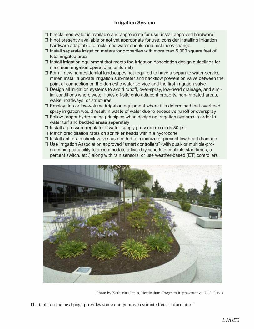
LWUE3
Irrigation System
If reclaimed water is available and appropriate for use, install approved hardware If not presently available or not yet appropriate for use, consider installing irrigation hardware adaptable to reclaimed water should circumstances changeInstall separate irrigation meters for properties with more than 5,000 square feet of total irrigated areaInstall irrigation equipment that meets the Irrigation Association design guidelines for maximum irrigation operational uniformityFor all new nonresidential landscapes not required to have a separate water-service meter, install a private irrigation sub-meter and backflow prevention valve between the point of connection on the domestic water service and the first irrigation valveDesign all irrigation systems to avoid runoff, over-spray, low-head drainage, and simi-lar conditions where water flows off-site onto adjacent property, non-irrigated areas, walks, roadways, or structuresEmploy drip or low-volume irrigation equipment where it is determined that overhead spray irrigation would result in waste of water due to excessive runoff or oversprayFollow proper hydrozoning principles when designing irrigation systems in order to water turf and bedded areas separatelyInstall a pressure regulator if water-supply pressure exceeds 80 psiMatch precipitation rates on sprinkler heads within a hydrozoneInstall anti-drain check valves as needed to minimize or prevent low head drainageUse Irrigation Association approved “smart controllers” (with dual- or multiple-pro-gramming capability to accommodate a five-day schedule, multiple start times, a percent switch, etc.) along with rain sensors, or use weather-based (ET) controllers
❒
❒
❒
❒
❒
❒
❒
❒
❒
❒
❒
❒
Photo by Katherine Jones, Horticulture Program Representative, U.C. Davis
The table on the next page provides some comparative estimated-cost information.
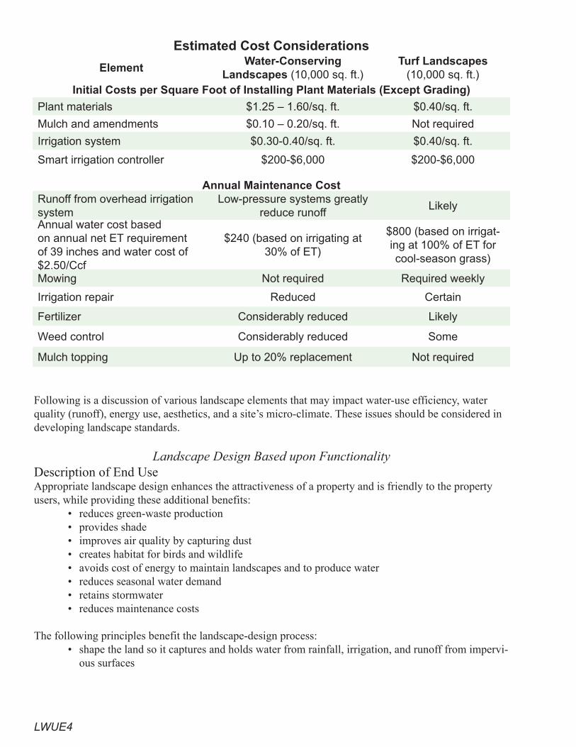
LWUE4
Estimated Cost Considerations
ElementWater-Conserving
Landscapes (10,000 sq. ft.)Turf Landscapes
(10,000 sq. ft.)Initial Costs per Square Foot of Installing Plant Materials (Except Grading)
Plant materials $1.25 – 1.60/sq. ft. $0.40/sq. ft.
Mulch and amendments $0.10 – 0.20/sq. ft. Not required
Irrigation system $0.30-0.40/sq. ft. $0.40/sq. ft.
Smart irrigation controller $200-$6,000 $200-$6,000
Annual Maintenance Cost Runoff from overhead irrigation system
Low-pressure systems greatly reduce runoff
Likely
Annual water cost based on annual net ET requirement of 39 inches and water cost of $2.50/Ccf
$240 (based on irrigating at 30% of ET)
$800 (based on irrigat-ing at 100% of ET for cool-season grass)
Mowing Not required Required weekly
Irrigation repair Reduced Certain
Fertilizer Considerably reduced Likely
Weed control Considerably reduced Some
Mulch topping Up to 20% replacement Not required
Following is a discussion of various landscape elements that may impact water-use efficiency, water quality (runoff), energy use, aesthetics, and a site’s micro-climate. These issues should be considered in developing landscape standards.
Landscape Design Based upon FunctionalityDescription of End UseAppropriate landscape design enhances the attractiveness of a property and is friendly to the property users, while providing these additional benefits:
• reduces green-waste production• provides shade• improves air quality by capturing dust• creates habitat for birds and wildlife• avoids cost of energy to maintain landscapes and to produce water• reduces seasonal water demand• retains stormwater • reduces maintenance costs
The following principles benefit the landscape-design process:• shape the land so it captures and holds water from rainfall, irrigation, and runoff from impervi-
ous surfaces
LWUE�
• ensure that the landscape soil has enough holding capacity to retain received water (see the subsection “Grading, Runoff, Soil Preparation and Mulches”).
• choose proper landscape plant material to fit climate and use (see subsection on “Plant Selection”).
• install efficient irrigation equipment (see subsection on “Irrigation Systems”).• maximize use of on-site water sources, e.g., re-irrigate with runoff or use reclaimed process
water; use other sources of reclaimed water where available (see subsection on “Irrigation Systems”).
Site designs need to conform to local stormwater management requirements, such as the following: • maximize infiltration to promote movement of stormwater downward through soils to remove
pollutants and restore surface and groundwater flows• provide retention• slow runoff• minimize impervious land cover• prohibit dumping of improper materials• retain pollutants• collect and convey stormwater or use for irrigation
Explanations of these objectives are provided in the “Grading, Runoff, Soil Preparation, and Mulches” subsection.
Good practices for water conservation are in many cases identical to good stormwater-management practices. One common goal is to shape the land and provide sufficient soil depth to slow runoff and retain the water that falls, in order to maximize infiltration into the soil. In most cases soil that retains water is the most cost-effective rainwater-harvesting technique.
Water-Savings Potential Based upon Functionality of DesignThe following practices help maximize water savings:
• Shape the land so it captures and holds water it receives from irrigation, rainfall, and runoff from impervious surfaces. Irrigation water should be retained in the soil. Stormwater can be retained in the soil and impoundments.
• Hydrozones comprise distinct groups of plants designed to have the same watering require-ments. Use separate stations to irrigate plants that have been grouped together according to their high, medium, or low water needs. When high- and low-water-use plants are mixed in a hydrozone — an area watered by the same irrigation valve or station — it is impossible to ap-ply the correct amount of water.
• Design water features, e.g., fountains, to recirculate water or use recycled wastewater treated to human-contact standards. See “Pools, Spas, and Fountains.”
• Avoid using turf on strips less than eight-feet wide or on slopes greater than 10 percent. Veg-etative strips in parking areas and highway medians and between sidewalks and pavement should be mulched, planted with water-thrifty shrubs, and irrigated with low-pressure systems.
• Adjacent to pavement and other hardscapes, use a mulched border at least two-feet wide comprising shrubs, groundcover, or other landscape treatment that is not spray irrigated. This minimizes runoff from errant sprays of overhead sprinklers.
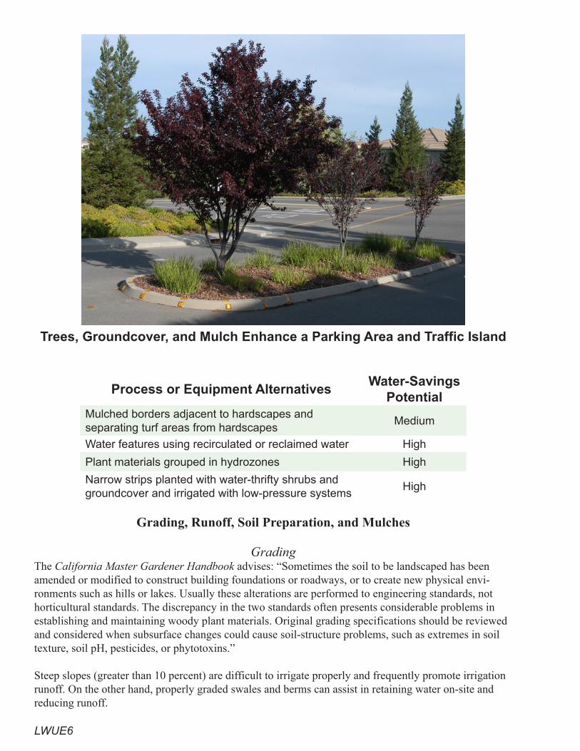
LWUE6
Trees, Groundcover, and Mulch Enhance a Parking Area and Traffic Island
Process or Equipment AlternativesWater-Savings
PotentialMulched borders adjacent to hardscapes and separating turf areas from hardscapes
Medium
Water features using recirculated or reclaimed water High
Plant materials grouped in hydrozones High
Narrow strips planted with water-thrifty shrubs and groundcover and irrigated with low-pressure systems
High
Grading, Runoff, Soil Preparation, and Mulches
GradingThe California Master Gardener Handbook advises: “Sometimes the soil to be landscaped has been amended or modified to construct building foundations or roadways, or to create new physical envi-ronments such as hills or lakes. Usually these alterations are performed to engineering standards, not horticultural standards. The discrepancy in the two standards often presents considerable problems in establishing and maintaining woody plant materials. Original grading specifications should be reviewed and considered when subsurface changes could cause soil-structure problems, such as extremes in soil texture, soil pH, pesticides, or phytotoxins.”
Steep slopes (greater than 10 percent) are difficult to irrigate properly and frequently promote irrigation runoff. On the other hand, properly graded swales and berms can assist in retaining water on-site and reducing runoff.

LWUE7
RunoffSome counties and municipalities may require Stormwater Control Plans and may, therefore, include such language as: “Every application for a development project … or building permit that is subject to the development runoff requirements in the … NPDES permit shall be accompanied by a Stormwater Control Plan that meets the criteria cited in the [Alameda] County Clean Water Program Stormwater Guidebook.”
Stormwater control plans are submitted with applications for planning and zoning review. The Stormwa-ter Control Plan is to be coordinated and integrated with the site plan, drainage plan, and landscaping.
Stormwater runoff is a concern when landforms are covered with impervious materials. Without the abil-ity to soak into soils and be slowed by vegetation, stormwater collects in large volumes that flow down-hill at accelerating speeds over impervious surfaces. This means higher storm-peak flows, potentially contributing to downstream flooding and greater erosion rates.
Relationship between Impervious Cover and Surface Runoff (FISRWG 1998)
The objectives of stormwater control plans are to minimize potential runoff pollution and runoff flows for the life of the project. The targeted pollutants include those deposited in airborne dust, liquids and dust from automobiles, cleaning solutions (e.g., from food service), litter, and trash.

LWUE8
Post-construction stormwater-control measures can be divided into four categories: • site design• source controls• stormwater treatment• hydro-modification management
Each category may include landscape measures, depending upon site conditions and design.
Depending upon local conditions, factors such as high clay content, soil susceptibility to liquefaction, soil contamination from prior activities, or seismic activity may require stormwater-control measures to be focused on flow filtration and temporary retention rather than deep percolation.
Description of End UseStormwater-control measures that affect landscapes include:
• minimizing land disturbance and preserving high-quality open space• minimizing impervious surfaces by using narrow streets, driveways, and sidewalks• using pervious surfaces • clustering structures and paved surfaces together• using landscaping as a drainage feature• building bioretention areas• extending detention basins• building infiltration trenches • using media filters • employing vegetated buffer strips• using vegetated swales• building retention ponds and vaults• using tree-well filters• employing flow-through planter boxes
Stormwater Water-Savings PotentialA Mediterranean climate may make stormwater an impractical supply without supplementary irriga-tion during the dry months. Due to concerns about disease, such as West Nile Virus, some agencies may specify a maximum number of days for standing water, based upon the incubation period of local mos-quito species.
Turf Block and Paver Mat (Alameda CCWP, 2006)
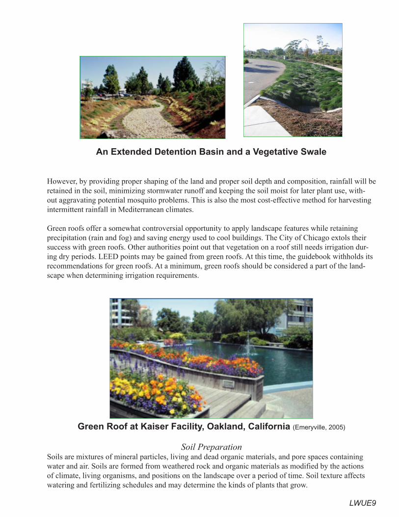
LWUE9
An Extended Detention Basin and a Vegetative Swale
However, by providing proper shaping of the land and proper soil depth and composition, rainfall will be retained in the soil, minimizing stormwater runoff and keeping the soil moist for later plant use, with-out aggravating potential mosquito problems. This is also the most cost-effective method for harvesting intermittent rainfall in Mediterranean climates.
Green roofs offer a somewhat controversial opportunity to apply landscape features while retaining precipitation (rain and fog) and saving energy used to cool buildings. The City of Chicago extols their success with green roofs. Other authorities point out that vegetation on a roof still needs irrigation dur-ing dry periods. LEED points may be gained from green roofs. At this time, the guidebook withholds its recommendations for green roofs. At a minimum, green roofs should be considered a part of the land-scape when determining irrigation requirements.
Green Roof at Kaiser Facility, Oakland, California (Emeryville, 2005)
Soil PreparationSoils are mixtures of mineral particles, living and dead organic materials, and pore spaces containing water and air. Soils are formed from weathered rock and organic materials as modified by the actions of climate, living organisms, and positions on the landscape over a period of time. Soil texture affects watering and fertilizing schedules and may determine the kinds of plants that grow.
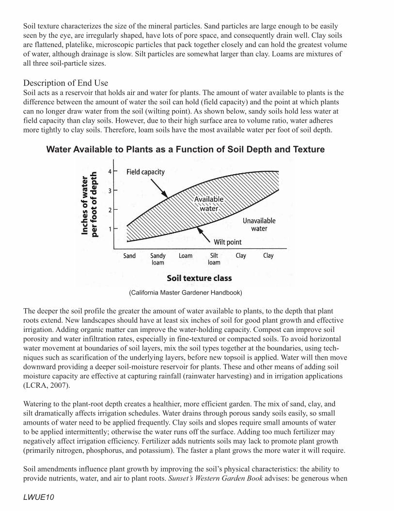
LWUE10
Soil texture characterizes the size of the mineral particles. Sand particles are large enough to be easily seen by the eye, are irregularly shaped, have lots of pore space, and consequently drain well. Clay soils are flattened, platelike, microscopic particles that pack together closely and can hold the greatest volume of water, although drainage is slow. Silt particles are somewhat larger than clay. Loams are mixtures of all three soil-particle sizes.
Description of End UseSoil acts as a reservoir that holds air and water for plants. The amount of water available to plants is the difference between the amount of water the soil can hold (field capacity) and the point at which plants can no longer draw water from the soil (wilting point). As shown below, sandy soils hold less water at field capacity than clay soils. However, due to their high surface area to volume ratio, water adheres more tightly to clay soils. Therefore, loam soils have the most available water per foot of soil depth.
Water Available to Plants as a Function of Soil Depth and Texture
(California Master Gardener Handbook)
The deeper the soil profile the greater the amount of water available to plants, to the depth that plant roots extend. New landscapes should have at least six inches of soil for good plant growth and effective irrigation. Adding organic matter can improve the water-holding capacity. Compost can improve soil porosity and water infiltration rates, especially in fine-textured or compacted soils. To avoid horizontal water movement at boundaries of soil layers, mix the soil types together at the boundaries, using tech-niques such as scarification of the underlying layers, before new topsoil is applied. Water will then move downward providing a deeper soil-moisture reservoir for plants. These and other means of adding soil moisture capacity are effective at capturing rainfall (rainwater harvesting) and in irrigation applications (LCRA, 2007).
Watering to the plant-root depth creates a healthier, more efficient garden. The mix of sand, clay, and silt dramatically affects irrigation schedules. Water drains through porous sandy soils easily, so small amounts of water need to be applied frequently. Clay soils and slopes require small amounts of water to be applied intermittently; otherwise the water runs off the surface. Adding too much fertilizer may negatively affect irrigation efficiency. Fertilizer adds nutrients soils may lack to promote plant growth (primarily nitrogen, phosphorus, and potassium). The faster a plant grows the more water it will require.
Soil amendments influence plant growth by improving the soil’s physical characteristics: the ability to provide nutrients, water, and air to plant roots. Sunset’s Western Garden Book advises: be generous when

LWUE11
adding organic amendments. When preparing a new planting bed, spread a three- to four-inch layer of amendment over the soil. Some authorities suggest tilling the amendments into the top four to nine inches; others authorities take a more natural approach without tilling. Around established plantings, add organic material by spreading it over the soil surface as mulch. Earthworms, microorganisms, and water will help mix it into the top layer of soil. Factors to consider when choosing a soil amendment:
• how long the amendment will last in the soil • soil texture• soil salinity and plant sensitivity to salts• salt content and pH of the amendment• the impact on beneficial soil microorganisms and fauna
MulchesMulches are opaque organic or inert materials put in layers on top of bare soil and around trees and shrubs. The purpose of mulches is to reduce water evaporation, prevent weeds by stopping photosynthe-sis, buffer soil temperatures, protect irrigation systems from harmful solar rays, and give the garden a finished look. Mulch should be porous to air and water. The coarser the material, the thicker the mulch layer needs to be. Organic mulch, such as shredded cedar bark or compost, will also amend the soil as it decomposes. To prevent crown rot and other problems, avoid applying mulch up against the main stem or trunk of a plant. Mulch is reported to reduce watering demand by 40 to 70 percent.
Alternative irrigation techniques should be used with plants surrounded by mulch. Apply water with bubblers, soaker hoses, or drip lines beneath the mulch to the plant-root areas. Sprinklers are inefficient methods of applying water to mulched areas, since mulch materials restrict water flow and absorb large amounts of water before it is able to reach the soil.
Water-Savings PotentialExample: a 10,000 square foot area planted in shrubs and trees with a four-inch layer of mulch. Mulch substantially reduces labor for weeding, but may need as much as 20 percent replacement each year, as it deteriorates into beneficial organic material for the soil.
• Material Capital Costs: Approximately 100 cu. yd. @ $10/cu. yd. = $1,000 (prices actually range from $0 to $40/cu. yd.). Add installation labor @ 1 hour/cu. yd. @ $10/hour = $1,000. Total cost of installed mulch = $2,000.
• Estimated Material Life: Five years.• Water and Energy Savings: Assume: 50 percent water savings due to mulch, traditional shrubs,
and ground cover (Ks=0.8). Dry season (May through October) ETo of 39 inches; plant spe-cies using water at a rate of 80 percent of ETo.
Water Savings Using MulchWith Mulch Without Mulch
Dry season water use in AF 0.371 0.742
Value of irrigation water $381 $763
Maintenance without mulch requires periodic weed-spraying and weed-removal. The mulch requires as much as 20 percent or more replacement annually, as the organic material deteriorates into soil amend-ments. The mulch provides an annual benefit of approximately $75.
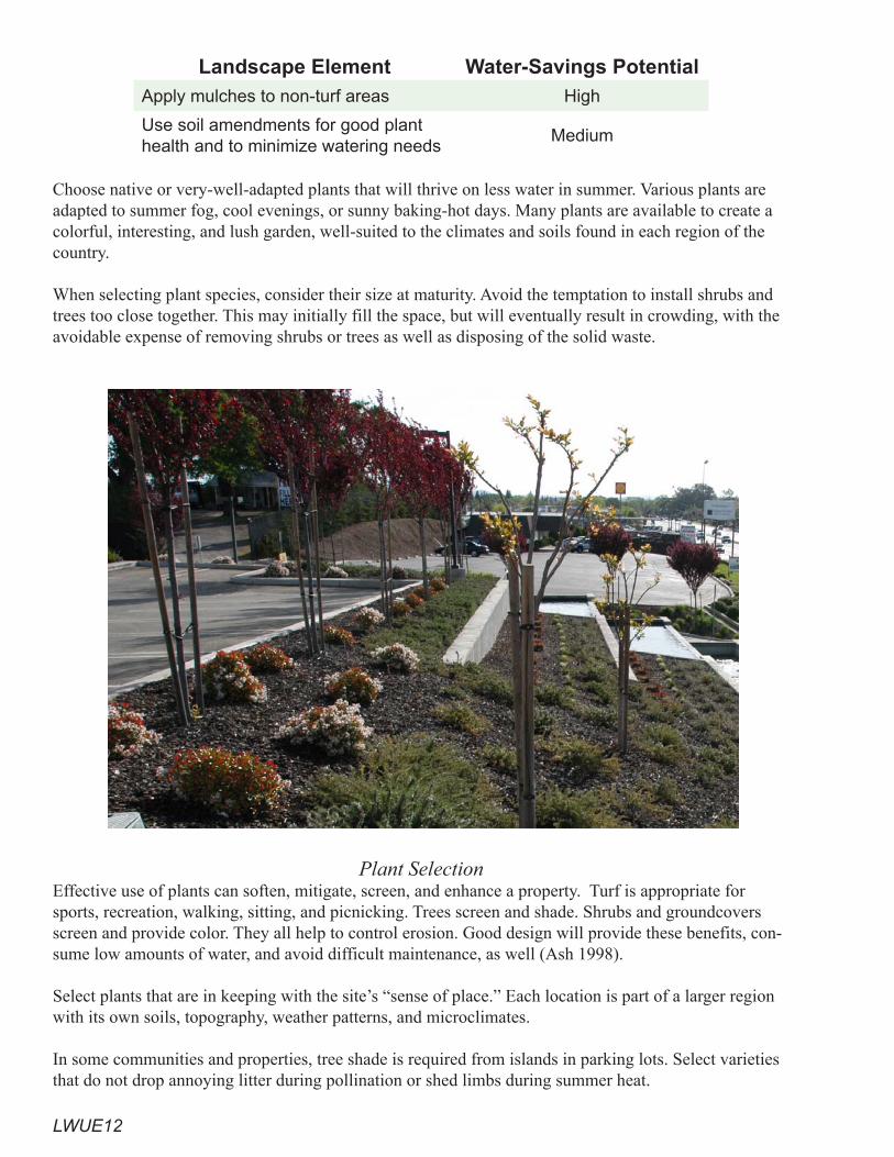
LWUE12
Landscape Element Water-Savings PotentialApply mulches to non-turf areas High
Use soil amendments for good plant health and to minimize watering needs
Medium
Choose native or very-well-adapted plants that will thrive on less water in summer. Various plants are adapted to summer fog, cool evenings, or sunny baking-hot days. Many plants are available to create a colorful, interesting, and lush garden, well-suited to the climates and soils found in each region of the country. When selecting plant species, consider their size at maturity. Avoid the temptation to install shrubs and trees too close together. This may initially fill the space, but will eventually result in crowding, with the avoidable expense of removing shrubs or trees as well as disposing of the solid waste.
Plant SelectionEffective use of plants can soften, mitigate, screen, and enhance a property. Turf is appropriate for sports, recreation, walking, sitting, and picnicking. Trees screen and shade. Shrubs and groundcovers screen and provide color. They all help to control erosion. Good design will provide these benefits, con-sume low amounts of water, and avoid difficult maintenance, as well (Ash 1998).
Select plants that are in keeping with the site’s “sense of place.” Each location is part of a larger region with its own soils, topography, weather patterns, and microclimates.
In some communities and properties, tree shade is required from islands in parking lots. Select varieties that do not drop annoying litter during pollination or shed limbs during summer heat.
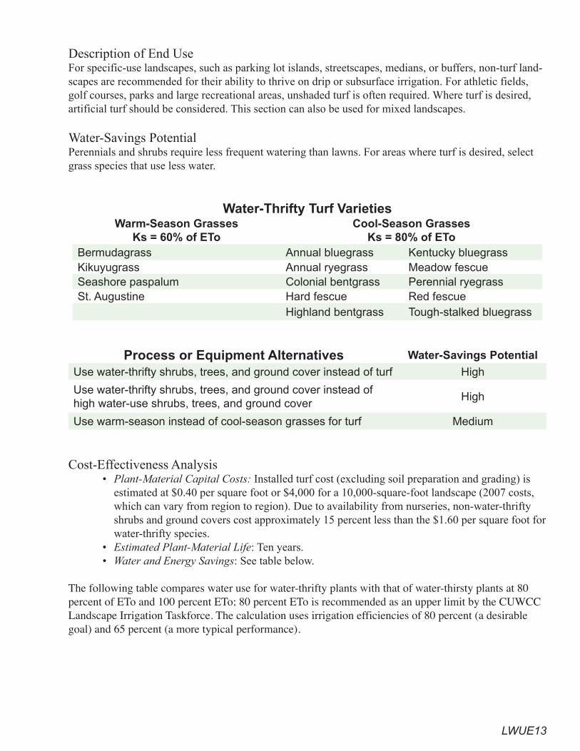
LWUE13
Description of End UseFor specific-use landscapes, such as parking lot islands, streetscapes, medians, or buffers, non-turf land-scapes are recommended for their ability to thrive on drip or subsurface irrigation. For athletic fields, golf courses, parks and large recreational areas, unshaded turf is often required. Where turf is desired, artificial turf should be considered. This section can also be used for mixed landscapes.
Water-Savings PotentialPerennials and shrubs require less frequent watering than lawns. For areas where turf is desired, select grass species that use less water.
Water-Thrifty Turf VarietiesWarm-Season Grasses
Ks = 60% of EToCool-Season Grasses
Ks = 80% of EToBermudagrass Annual bluegrass Kentucky bluegrassKikuyugrass Annual ryegrass Meadow fescueSeashore paspalum Colonial bentgrass Perennial ryegrassSt. Augustine Hard fescue Red fescue
Highland bentgrass Tough-stalked bluegrass
Process or Equipment Alternatives Water-Savings Potential
Use water-thrifty shrubs, trees, and ground cover instead of turf High
Use water-thrifty shrubs, trees, and ground cover instead of high water-use shrubs, trees, and ground cover
High
Use warm-season instead of cool-season grasses for turf Medium
Cost-Effectiveness Analysis • Plant-Material Capital Costs: Installed turf cost (excluding soil preparation and grading) is
estimated at $0.40 per square foot or $4,000 for a 10,000-square-foot landscape (2007 costs, which can vary from region to region). Due to availability from nurseries, non-water-thrifty shrubs and ground covers cost approximately 15 percent less than the $1.60 per square foot for water-thrifty species.
• Estimated Plant-Material Life: Ten years.• Water and Energy Savings: See table below.
The following table compares water use for water-thrifty plants with that of water-thirsty plants at 80 percent of ETo and 100 percent ETo; 80 percent ETo is recommended as an upper limit by the CUWCC Landscape Irrigation Taskforce. The calculation uses irrigation efficiencies of 80 percent (a desirable goal) and 65 percent (a more typical performance).

LWUE14
Average Irrigation Season (May – October) Water Use and Water Costs
10,000 square foot area
Plant type Budget 80% ET Budget 100% ET
Irrigation System
Efficiency (percent)
Gallons/AFWater Fees*
Gallons/AFWater Fees*
Low-water-using plants
8072,500 0.223
$23090,600 0.278
$286
Low-water-using plants
6589,2800.274
$282111,6000.342
$352
Low-water-using plants with mulch
8036,2700.111
$11445,3400.139
$143
Low-water-using plants with mulch
6544,6400.137
$14155,8000.171
$176
Warm-season grasses80
145,000 0.445
$458181,300
0.557$572
Warm-season grasses65
178,5600.548
$563223,200
0.685$704
Turf with cool-season grasses
80193,400
0.594$610
241,800 0.742
$763
Turf with cool-season grasses
65238,080
0.731$751
297,6000.913
$939
*Irrigated landscapes that are metered independently from interior uses are spared fees for wastewater services. This table assumes a May to October ETo of 39 inches.
Because turf is mowed frequently, may require more fertilizer than shrubs, and needs other maintenance, the annual maintenance cost of turf is approximately 25 to 30 percent higher than that for permanent shrubs and ground cover.
Incremental Cost per AF of Water-Efficient Plant Materials*
Present Value Benefitof Water Savings
Benefit /AF over Plant Lifetime
Low-water-using shrubs vs. thirsty shrubs
$2,945 $794
Warm-season grasses vs. thirsty grasses
$1,178$794
Low-water-using shrubs vs. thirsty grasses
$4,124 $794
*For simplicity, maintenance costs, such as weeding and mowing, are excluded.
LWUE1�
Irrigation SystemsIrrigation systems replace water in the soil that is used by shrubs, trees, and grass, where natural mois-ture is inadequate for the intended landscape. Without regard to the type of landscape, the primary guideline for landscape irrigation design is to avoid over-watering by applying:
• the right amount of water• to the right place • at the right time
The proper design of an irrigation system takes into account:• types of plants and their spatial distribution• slope, soils, and soil amendments• climate factors, such as wind and ET rates• zero runoff goal from the area to be irrigated • adjacent structures, features, and hardscapes
Description of End UseTo replace the soil moisture, an irrigation system receives water from a source and distributes it to plants when desired.
Irrigation-System ComponentsTypical components of irrigation systems include:
• water meter: measures the volume of water entering the system• backflow prevention device: prevents potentially contaminated water from an irrigation sys-
tem from flowing into a potable-water system• pressure regulator: controls water pressure within set limits• pressure reducer: reduces water pressure to desired range• controller: regulates the irrigation cycles to activate the control valves at the times and days
selected• soil moisture sensor: installed at the root zone at strategic locations representing the irrigation
zone; signals the controller if irrigation cycles may be omitted• rain sensor: detects recent rainfall and signals the controller if irrigation cycles may be omitted• valve: allows water flow when actuated by controller• anti-drain check valve: prevents water loss from sprinklers or emitters at low spots in the ir-
rigation system• sprinkler head: emits streams of water through the air to plants• filter: removes from water oversized particles that might clog emitters• bubbler: head that emits flows short distances at 0.25-2 gpm• drip emitter: low-pressure device that emits water drops at rates of 0.5 to 2 gph• micro-spray: low-pressure device that sprays water a short distance at flows of .5 to 5 gph• drip or soaker line: tubing that emits water along its length • zone: a portion of the landscape with the same irrigation requirements
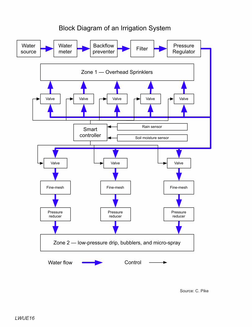
LWUE16
Source: C. Pike
Valve Valve Valve
Fine-mesh Fine-mesh Fine-mesh
Pressurereducer
Pressurereducer
Pressurereducer
Watersource
Watermeter
Backflowpreventer
FilterPressureRegulator
Zone 1 — Overhead Sprinklers
Valve Valve Valve Valve Valve
Smartcontroller
Rain sensor
Soil moisture sensor
Zone 2 — low-pressure drip, bubblers, and micro-spray
Block Diagram of an Irrigation System
Water flow Control
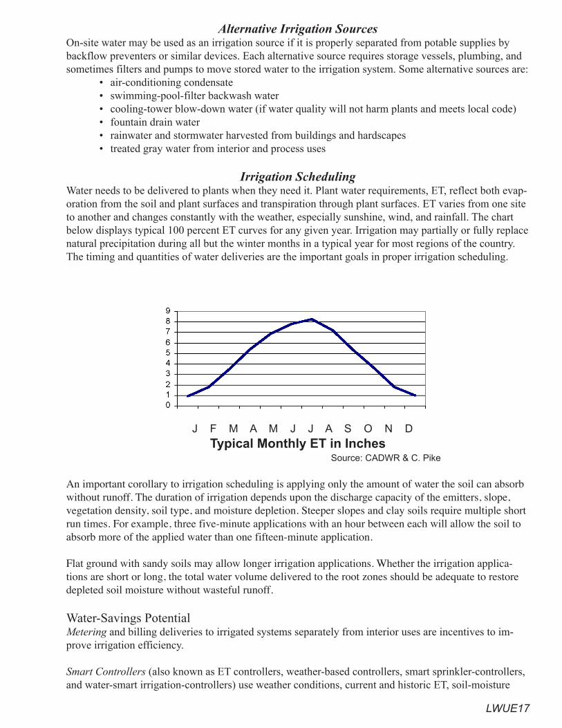
LWUE17
Alternative Irrigation SourcesOn-site water may be used as an irrigation source if it is properly separated from potable supplies by backflow preventers or similar devices. Each alternative source requires storage vessels, plumbing, and sometimes filters and pumps to move stored water to the irrigation system. Some alternative sources are:
• air-conditioning condensate • swimming-pool-filter backwash water• cooling-tower blow-down water (if water quality will not harm plants and meets local code)• fountain drain water• rainwater and stormwater harvested from buildings and hardscapes• treated gray water from interior and process uses
Irrigation SchedulingWater needs to be delivered to plants when they need it. Plant water requirements, ET, reflect both evap-oration from the soil and plant surfaces and transpiration through plant surfaces. ET varies from one site to another and changes constantly with the weather, especially sunshine, wind, and rainfall. The chart below displays typical 100 percent ET curves for any given year. Irrigation may partially or fully replace natural precipitation during all but the winter months in a typical year for most regions of the country. The timing and quantities of water deliveries are the important goals in proper irrigation scheduling.
J F M A M J J A S O N DTypical Monthly ET in Inches
Source: CADWR & C. Pike
An important corollary to irrigation scheduling is applying only the amount of water the soil can absorb without runoff. The duration of irrigation depends upon the discharge capacity of the emitters, slope, vegetation density, soil type, and moisture depletion. Steeper slopes and clay soils require multiple short run times. For example, three five-minute applications with an hour between each will allow the soil to absorb more of the applied water than one fifteen-minute application.
Flat ground with sandy soils may allow longer irrigation applications. Whether the irrigation applica-tions are short or long, the total water volume delivered to the root zones should be adequate to restore depleted soil moisture without wasteful runoff.
Water-Savings PotentialMetering and billing deliveries to irrigated systems separately from interior uses are incentives to im-prove irrigation efficiency.
Smart Controllers (also known as ET controllers, weather-based controllers, smart sprinkler-controllers, and water-smart irrigation-controllers) use weather conditions, current and historic ET, soil-moisture
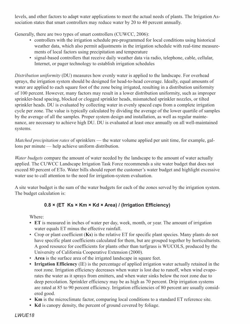
LWUE18
levels, and other factors to adapt water applications to meet the actual needs of plants. The Irrigation As-sociation states that smart controllers may reduce water by 20 to 40 percent annually.
Generally, there are two types of smart controllers (CUWCC, 2006):• controllers with the irrigation schedule pre-programmed for local conditions using historical
weather data, which also permit adjustments in the irrigation schedule with real-time measure-ments of local factors using precipitation and temperature
• signal-based controllers that receive daily weather data via radio, telephone, cable, cellular, Internet, or pager technology to establish irrigation schedules
Distribution uniformity (DU) measures how evenly water is applied to the landscape. For overhead sprays, the irrigation system should be designed for head-to-head coverage. Ideally, equal amounts of water are applied to each square foot of the zone being irrigated, resulting in a distribution uniformity of 100 percent. However, many factors may result in a lower distribution uniformity, such as improper sprinkler-head spacing, blocked or clogged sprinkler heads, mismatched sprinkler nozzles, or tilted sprinkler heads. DU is evaluated by collecting water in evenly spaced cups from a complete irrigation cycle per zone. The value is typically calculated by dividing the average of the lower quartile of samples by the average of all the samples. Proper system design and installation, as well as regular mainte-nance, are necessary to achieve high DU. DU is evaluated at least once annually on all well-maintained systems.
Matched precipitation rates of sprinklers — the water volume applied per unit time, for example, gal-lons per minute — help achieve uniform distribution.
Water budgets compare the amount of water needed by the landscape to the amount of water actually applied. The CUWCC Landscape Irrigation Task Force recommends a site water budget that does not exceed 80 percent of ETo. Water bills should report the customer’s water budget and highlight excessive water use to call attention to the need for irrigation-system evaluation.
A site water budget is the sum of the water budgets for each of the zones served by the irrigation system. The budget calculation is:
0.8 × (ET Ks × Km × Kd × Area) / (Irrigation Efficiency)
Where: • ET is measured in inches of water per day, week, month, or year. The amount of irrigation
water equals ET minus the effective rainfall.• Crop or plant coefficient (Ks) is the relative ET for specific plant species. Many plants do not
have specific plant coefficients calculated for them, but are grouped together by horticulturists. A good resource for coefficients for plants other than turfgrass is WUCOLS, produced by the University of California Cooperative Extension (2000).
• Area is the surface area of the irrigated landscape in square feet.• Irrigation Efficiency (IE) is the percentage of applied irrigation water actually retained in the
root zone. Irrigation efficiency decreases when water is lost due to runoff, when wind evapo-rates the water as it sprays from emitters, and when water sinks below the root zone due to deep percolation. Sprinkler efficiency may be as high as 70 percent. Drip irrigation systems are rated at 85 to 90 percent efficiency. Irrigation efficiencies of 80 percent are usually consid-ered good.
• Km is the microclimate factor, comparing local conditions to a standard ET reference site.• Kd is canopy density, the percent of ground covered by foliage.
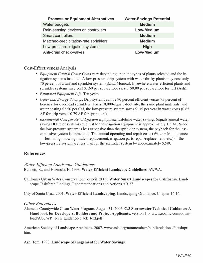
LWUE19
Process or Equipment Alternatives Water-Savings PotentialWater budgets MediumRain-sensing devices on controllers Low-MediumSmart controllers MediumMatched-precipitation-rate sprinklers MediumLow-pressure irrigation systems HighAnti-drain check-valves Low-Medium
Cost-Effectiveness Analysis • Equipment Capital Costs: Costs vary depending upon the types of plants selected and the ir-
rigation systems installed. A low-pressure drip system with water-thrifty plants may cost only 70 percent of a turf and sprinkler system (Santa Monica). Elsewhere water-efficient plants and sprinkler systems may cost $1.60 per square foot versus $0.80 per square foot for turf (Ash).
• Estimated Equipment Life: Ten years.• Water and Energy Savings: Drip systems can be 90 percent efficient versus 75 percent ef-
ficiency for overhead sprinklers. For a 10,000-square-foot site, the same plant materials, and water costing $2.50 per Ccf, the low-pressure system saves $135 per year in water costs (0.65 AF for drip versus 0.79 AF for sprinklers).
• Incremental Cost per AF of Efficient Equipment: Lifetime water savings (equals annual water savings × life of systems) due just to the irrigation equipment is approximately 1.3 AF. Since the low-pressure system is less expensive than the sprinkler system, the payback for the less-expensive system is immediate. The annual operating and repair costs (Water + Maintenance — fertilizing, mowing, mulch replacement, irrigation parts repair/replacement, etc.) of the low-pressure system are less than for the sprinkler system by approximately $240.
References
Water-Efficient Landscape GuidelinesBennett, R., and Hazinski, H. 1993. Water-Efficient Landscape Guidelines. AWWA.
California Urban Water Conservation Council. 2005. Water Smart Landscapes for California. Land-scape Taskforce Findings, Recommendations and Actions AB 271.
City of Santa Cruz. 2001. Water-Efficient Landscaping. Landscaping Ordinance, Chapter 16.16.
Other ReferencesAlameda Countywide Clean Water Program. August 31, 2006. C.3 Stormwater Technical Guidance: A
Handbook for Developers, Builders and Project Applicants, version 1.0. www.eoainc.com/down-load/ACCWP_Tech_guidance-black_text.pdf.
American Society of Landscape Architects. 2007. www.asla.org/nonmembers/publicrelations/factshtpr.htm.
Ash, Tom. 1998. Landscape Management for Water Savings.
LWUE20
California Stormwater Quality Association. 2003. California Storm Water Quality Association Storm Water BMP Handbooks for Industrial Activity, Construction, Municipal Operations and New Develop-ment/Redevelopment. www.cabmphandbooks.org/Development.asp.
California Urban Water Conservation Council. August 2006. Interim Process Evaluation Report on Prop. 13 Smart Controller Programs.
City of Santa Monica. August 2006. Garden/Garden: A Comparison of Native and Traditional Gar-dens in Santa Monica.
City of Santa Monica. March 2006. Guide to Successful Drip Irrigation for Landscape Professionals.
Colorado State University Cooperative Extension. Choosing a Soil Amendment. No. 07235. www.ext.colostate.edu/PUBS/GARDEN/07235.html.
Contra Costa County Clean Water Program. December 2006. Stormwater Quality Requirements for Development Applications.
East Bay Municipal Utility District. 2004. Plants and Landscapes for Summer-Dry Climates of the San Francisco Bay Region.
Federal Interagency Stream Restoration Working Group (FISRWG). October 1998. Stream Corridor Restoration: Principles, Processes, and Practices.
GardenGuides.com. Guide to Selecting a Garden Mulch. www.gardenguides.com/how-to/tipstech-niques/composting/mulch-noframe.asp.
Irrigation Association. Smart Water Application Technologies. www.irrigation.org/SWAT/Industry/.
Lower Colorado River Authority. 2007. LCRA Soil Depth and Soil Amendment Specifications—Background.
Metro Water Conservation Inc. December 2004. Yield and Reliability Demonstrated in Xeriscape Final Report.
New Mexico Office of the State Engineer. 1999. A Water Conservation Guide for Commercial insti-tutional and Industrial Users.
Nilsson Associates. Labor Time Data Handbook. www.nilssonbooks.com.
San Francisco Bay Regional Water Quality Control Board. Stormwater Program. www.waterboards.ca.gov/sanfranciscobay/programs.html#stormwater.
State of California. Water Conservation in Landscaping Act: Assembly Bill 1881. September 2006, www.leginfo.ca.gov.
StopWaste.org. Bay-Friendly Landscape Guidelines.
Sunset Publishing Corporation. 2001. Western Garden Book.

LWUE21
University of California. Agriculture and Natural Resources. 2002. California Master Gardener Hand-book, publication 3382.
University of California Cooperative Extension. 2000. A Guide to Estimating Irrigation Water Needs of Landscape Plantings in California. WUCOLS.
Western Policy Research. August 2004. LADWP Weather-Based Irrigation Controller Pilot Study.