Waterscapes, Fall 2012
24
A TECHNICAL PUBLICATION BY THE WATER GROUP OF HDR FALL 2012
description
In this issue of Waterscapes, we highlight projects from each type of water system facility for which condition assessments are done.
Transcript of Waterscapes, Fall 2012

2
Comprehensive Engineering Review for Metropolitan Utilities District’s Florence Water Treatment Plant
11
12 City of Scottsdale Reclaimed Water Distribution System (RWDS) Evaluation, Condition Assessment and Conceptual Design Improvements
20 Johnson County Unified Wastewater Districts Pumping Station Rehabilitation Projects
16 Rehabbing a Rehab in South Carolina5 108 Miles and Counting: Large Diameter Water Pipeline Condition Assessment
Extending Reservoir Service Life
contents

fa l l 2 0 1 2
Waterscapes is a technical publication produced and distributed by HDR. address
changes and correspondence should be sent to the attention of:
Waterscapes Editor Engineering Marketing Services
8404 Indian Hills DriveOmaha, NE 68114-4049
T e c H n i c a l e D i To RGraham Bell, Ph.D.
WaT e R s c a p e s e D i To RSteve Beideck
e D i T i n g & D e s i g nEngineering Marketing Services
www.hdrinc.com
© 2012 HDR, inc., all rights reserved
For information on career opportunities at HDR, please visit: www.hdrinc.com/careers
We practice increased use of sustainable materials and reduction of material use.
Waterscapes is offset printed on Utopia Two Xtra green 100# Dull text, which is fsc-
certified paper manufactured with electricity in the form of renewable energy (wind,
hydro, and biogas) and includes a minimum of 30% post-consumer recovered fiber.
[ front cover photo ]
one of four primary basins used for the split lime softening process at the
Metropolitan Utilities District’s florence Water Treatment plant in omaha, neb. a condition assessment revealed that
repairs to the bridges and mechanisms of each basin were necessary. This facility is the oldest in MUD’s system, which has
components that date back to 1889.
our ability to live together and form civilized society is directly the result of engineers to provide, process and remove water and waste streams for human populations. The systems which facilitate our civilization are pipelines, storage and treatment facilities.
as these systems age, decisions need to be made when to renew or how to extend the useful lives of these facilities. When economies are flourishing, replacement is an option. With diminishing resources, decisions have to be made based on information on which facilities need to be replaced or rehabilitated, or which operations/maintenance procedure(s) should be modified to extend the useful life to meet the owner’s needs.
The process by which we gather data and process information for those decisions is called condition assessment. in this issue of Waterscapes, we highlight projects from each type of water system facility for which condition assessments are conducted.
The first article by Tim Thomure focuses on the city of Tucson’s reservoir assessment project which includes steel and concrete reservoirs. Reservoirs often are forgotten in condition assessments since they are visible above ground and have few, if any, moving parts. However, reservoirs are critical to the consistency of water operations.
scott christensen and steven fox detail the three-year program to assess the southern nevada Water authority’s transmission piping system which consists of almost every type of pipe material.
glenn Dostal contributed two articles. His stories describe the multidisciplinary approach of condition assessment necessary for the water and wastewater plant facilities at MUD’s florence Water Treatment plant in omaha, neb., and the Unified Wastewater District pump station in Johnson county, Kan., in suburban Kansas city.
ed Junod details the process of condition assessment to conceptual design for the city of scottsdale Reclaimed Water Distribution system while Ken Von aspern, Tracy lewis and Walt fletcher discuss when one rehabilitation project begets another.
The engineer’s role is to turn data in to actionable information for the owner to use in asset management or facility life extension. These case studies highlight the processes and difficulty in conducting condition assessments on water system facilities.
complementing this issue is HDR’s new condition assessment wall chart, extending asset life, which details some of the technologies for condition assessment.
While technologies are valuable in providing data for analysis and consideration, condition assessment creates the needed actionable information. Using a combination of the appropriate technologies and engineering analysis, we can continue to be good stewards of the public trust and civilized society.
Graham Bell, Ph.D.Condition Assessment & Rehabilitation Practice Lead
1
message from technical editor

A raft inspection is performed with the
reservoir still in service to minimize operational impacts while collecting
critical data on roofing system conditions.
waterscapes | fall 2012
[ reservoir and tank rehabilitation ]
Extending Reservoir Service Life
By Timothy M. Thomure, P.E., P.M.P., Arizona Water Business Group Manager, Tucson, Ariz. Jim Pembroke, P.E., Vice President, Southwest Area Water Marketing Manager, Phoenix, Ariz.
ThE CiTy of TuCSon Water Department (Tucson Water) is entering the third year of a five-year initiative to develop a comprehensive reservoir management program. The initiative consists of multiple phases, including:• program development•condition assessments of 68 water
storage reservoirs• preparation of rehabilitation designs
for priority sites•construction activities to execute
the repairs
The Tucson Water Reservoir and Tank Rehabilitation Program
Tucson Water’s decision to develop this program reflects a wider industry trend toward infrastructure reinvestment.
The reservoir inventory is valued at over $250 million and includes all storage sites on Tucson Water’s potable and reclaimed water systems. There are 34 concrete/earth embankment reservoirs (0.65 mg to 60 mg capacity) and 34 steel storage tanks (10 kg to 2 mg capacity). These facilities were installed from the 1950s to the recent past, and over 50 percent of the sites are 25 years old or older.
2

services provided by HDR and its subconsultants have included:• steel tank triage assessments•concrete reservoir condition assessments•Data management• Rehabilitation capital planning• Rehabilitation design•construction inspection
Planning and Program Management
HDR worked closely with Tucson Water staff to develop the program from its inception. Key planning elements included development of a standardized condition assessment rating system (caRs), balancing repair priorities against the available capital budget, and goal-setting for targeted rehabilitation levels.
since the utility did not have a prior reservoir assessment program, HDR implemented a triage approach that consisted of site visits with expedited data collection to create a preliminary prioritization of all reservoirs for subsequent complete condition assessment and rehabilitation.
During triage assessments, the reservoir was kept in service and the following evaluations were conducted: • perimeter and site walk (safety, security,
lighting, signage, access, drainage and yard piping)
• exterior visual assessment (with spot dry film thickness measurements on steel tanks)
• Tank climb and exterior roof assessment • interior visual inspection from the hatch
(non-entry) all 68 reservoirs were visited for triage
within the first three months of the contract, greatly increasing the utility’s confidence in the initial capital planning effort.
all work was conducted under a program-specific safety plan developed by HDR in compliance with osHa and Tucson Water requirements.
Condition AssessmentsHDR adapted its assessment techniques
to match the utility’s program goals and the unique characteristics of steel tanks versus concrete reservoirs. concrete reservoirs tend to have a much wider variety of design approaches, construction specifications and roofing systems, among other factors, than steel storage tanks.
The relative consistency of steel tank construction – coupled with our experience in efficient assessment tools and techniques – allowed HDR to perform triage assessments on six to eight steel tanks each working day. as the steel tanks move into rehabilitation design based on their initial prioritization, dry tank inspections will be conducted to directly assess the floor, take steel thickness measurements and calculate seismic code compliance.
The concrete reservoirs underwent a similar triage assessment with consideration given to the wider variety of structural elements. To gather the remainder of the required assessment information on concrete sites, interior raft inspections are conducted (28 of 34 inspections have been completed to date).
With the reservoir full, the assessment team inspects the interior with specific emphasis on the columns, roofing system and liner (where present). There were 72-hour static leak tests performed, and previous dive inspections were reviewed to complete the data collection.
Upon completion of condition assessment activities on both the steel tanks and the concrete reservoirs, recommendations for rehabilitation are documented in comprehensive condition assessment reports. areas for improvement include:• structural repairs•Weather tightness• site conditions• safety/security performance•Water quality
planning level cost opinions are developed at the condition assessment stage to aid in capital planning for the utility.
information Managementinformation collected and developed
during the program is documented in condition assessment reports for each reservoir with planning level cost opinions for rehabilitation.
Cond
ition
Maintain Replace
DeferredMaintenance
PreventiveMaintenance
RehabilitateReplace
Water agencies have shifted their focus from meeting growth demands to extending infrastructure service life. in short, a change in attitude from deferred to preventive maintenance.
3www.hdrinc.com

waterscapes | fall 2012
That format of documentation is useful to a point; however, many stakeholders require access to only certain parts of the information contained in the reports and/or find other media more useful than “binders on the shelf.” in addition, it is critical to long-term program success to store the information in a consistent, accessible and updatable system.
To facilitate access, HDR provides condensed executive summary data sheets for each reservoir site (useful to management) and houses a sharepoint website dedicated to the program that allows end users access to navigate to all known data from as-built drawings, condition assessment reports, rehabilitation designs and daily construction inspection reports.
Rehabilitation Design and Construction
HDR has completed rehabilitation designs for three concrete reservoirs with two additional designs at 90 percent completion as of aug. 1, 2012. additional rehabilitation designs are added to the program each year for construction during the following winter season.
Rehabilitation designs to date have addressed issues including:• Roof improvements (cast-in-place
concrete, precast concrete single/double-tee, and standing seam aluminum)
• installation of spray applied and membrane liners
•corrosion repair and prevention• Ventilation improvements•Miscellaneous site improvements
HDR and our subconsultants provided engineering support through construction, construction observation and full-time third party inspection during coatings applications. Two reservoir rehabilitations have been completed to date totaling about $1.5 million. projects currently scheduled for winter 2012-13 total an additional $1.5 million.
Ultimately, the goals of the program are to extend the service life of the storage facilities, minimize water losses and protect water quality and public health. Through a phased approach of condition assessment, rehabilitation and planned maintenance, these goals will be achieved.
For additional information about this article, please contact Tim Thomure at Timothy.Thomure@hdrinc .com or Jim Pembroke at [email protected] .
[ reservoir and tank rehabilitation ]St
eel T
ank
/ Site
Con
ditio
n In
form
atio
n
Code ComplianceSteel ThicknessFloor ConditionWater ClarityVisual InteriorVisual StructuralVentilationCathodic ProtectionInterior Coating (Indirect)Exterior Roof CoatingExterior Shell CoatingLadders & RailsYard PipingSignageSite DrainageSecurity & FencingPrior WorkAge & MaterialsAs-Builts
100%
0%Level ofInvestment 100%
5% 20%
Through triage, hDR assessment teams gather approximately 80 percent of the data an owner may need to know about the asset at approximately 20 percent of the resource investment of a full condition assessment (steel tank example).
4

[ pipeline condition assessment ]
By Scott Christensen, P.E., Project Manager, Las Vegas, Nev. Steven Fox, P.E., Vice President and Project Manager, San Diego
year Diameter ranGe PiPe materials lenGth
i 14-120 inchesasbestos, steel, Reinforced concrete pipe, pre-stressed
concrete cylinder pipe24 miles
ii 21-102 inchespre-stressed concrete cylinder pipe, pre-tensioned (bar wrap) concrete cylinder pipe, steel
34 miles
iii 36-108 inches steel 50 miles
[ table 1 ] Summary of Laterals
&108 mileslarge Diameter Water pipeline condition Assessment
counting
in MAy 2007, pooling water on the desert floor was observed in the vicinity of the las Vegas lateral, a 90-inch diameter cement-mortar lined and coated steel pipe constructed in 1971. The subsequent investigation revealed that the exterior mortar had lost all alkalinity, the cement mortar coating had cracked, and the soils in the vicinity were extremely corrosive.
Up to 80 percent wall thinning of the 9/16” thick steel “can” and three holes had formed, resulting in the “wet spot” and critical system downtime. Repairs were initiated and completed by the owner and a local contractor.
following the repair and subsequent investigation on the las Vegas lateral, the southern nevada Water authority (snWa) initiated a program to assess water transmission laterals that were constructed prior to 2000 and retained the services of HDR to provide a condition assessment of approximately 108 miles of pipe in las Vegas (Table 1). The program was scheduled to be completed over a three-year period.
• corrosion testing and evaluation• internal inspection of pre-stressed concrete cylinder pipe (pccp)•acoustic testing•geotechnical investigation• surveying• Test station installation and excavations• Broadband electromagnetic testing• potholing
Criticality EvaluationThe initial project was envisioned to span three years. The first step
was to determine the order in which laterals would be inspected and evaluated. a criticality evaluation, using pairwise comparison to weigh and compare factors, was performed to prioritize the laterals for inspection. The required criteria for evaluation were developed along with specific scoring methodology for each criterion.
The results of the criticality evaluation provided a prioritized listing of the laterals to be inspected each year of the program. as seen in Table 2, criteria were developed for the evaluation and resulted in the following:•age – all pipes are pre-2000, but were defined by four age
categories, based on the installing authority: – stage 1, installed 1968-1971 – stage 2, installed 1974-1982 – cRc, installed 1992-1996 – cip, installed 1996-2005
•Coatings – Various pipe configurations have different types of applied (or manufactured) coatings. coatings are divided into cement-mortar applied; coatings integral with pipe structure such as pccp; dielectric only and dielectric with mortar overcoats.
•Cathodic protection – some of the laterals have cathodic protection (cp) systems installed; others do not. Test stations were initially on some laterals, but may have been removed, destroyed or “lost.” This category was divided into five categories – no cathodic protection and no test stations; no cathodic protection but has test stations; sacrificial cathodic protection with zinc or magnesium anodes; older impressed current system; and new impressed current system.
• system importance – as the only delivery system into the las Vegas Valley, all transmission laterals are important to the welfare of the valley. However, three categories were identified – main
During the Year iii work, the client requested that additional pipe be added to the investigation, bringing the Year iii length to approximately 80 miles.
The project team included specialized sub-consultants schiff associates (now HDR|schiff), pressure pipe inspection company (now pURe Technologies), echologics, Kleinfelder, TRc solutions, Rafael civil, Rock solid group, and cardno TBe for several tasks, including:
5www.hdrinc.com

waterscapes | fall 2012
hiGh low
Criteria 1 2 3 4 5
age stage 1 stage 2 CrC CiP (not used)
pipe coating Mortar coating coating with structural Dielectric (not used) Dielectric with mortar overcoat
cathodic protection no cp, without test stations
no cp, without test stations
sacrificial cp with anodes
older impressed current system, with
sacrificial anodes
new impressed current system
system importance Main with no backup Main with backup secondary (not used) (not used)
external conditions aggressive possible stray current (not used) non-aggressive clsM backfill
pipe Material asbestos pre-stressed (installed in 1970s)
pre-stressed (pre- or post 1970s) Rcp steel
age Coatings CP system importance
external Conditions
Pipe materials sum weighting
Factor
age 3 1 5 2 3 14 0.16
coatings 3 2 5 4 4 18 0.20
cp 5 4 5 3 5 22 0.24
system importance 1 1 1 1 1 5 0.06
external condition 4 2 3 5 5 19 0.21
pipe Material 3 2 1 5 1 12 0.13
total 90 1.00
[ table 2 ] Criteria Scoring
[ table 3 ] Pairwise Comparison Results
[ pipeline condition assessment ]
laterals with no backup or redundancy, main laterals with backup or redundancy, or secondary laterals.
• external conditions – This criterion addresses the potential aggressiveness and non-aggressiveness of the lateral’s environment. factors include soil and backfill conditions adjacent to the lateral in terms of soil resistivity (an indicator of soil and groundwater conditions meaning low soil resistivity would fall under aggressive external conditions and high soil resistivity falls under non-aggressive external conditions); trench backfill material (clsM, native, import); and potential stray current influence by nearby utilities. if the lateral is parallel to or crossed by another utility equipped with a cathodic protection system, this adjacent system can potentially expose the lateral stray currents, impacting the deterioration rates of the lateral.
•Pipe type – This category addresses the predicted performance of specific pipe types. lateral types include steel pipe, reinforced concrete pipe, asbestos cement pressure pipe, pre-stressed and pre-tensioned concrete cylinder
pipe. pre-stressed pipe is further defined by whether it was installed in the 1970s or pre- or post-1970.other criteria that were considered, but not used, included
internal pressures; transient pressures; linings; recent construction; future cip; maintenance history; and accessibility.
for this evaluation, a score of 1 indicates high priority and 5 indicates low priority.
The pairwise comparison Decision support Tool is used to provide a relative weighting of the criteria used for the criticality evaluation. This tool provides a simple way to compare criteria or alternatives against each other. Using numeric values between 1 and 5, with 5 being more important and 1 less important, a comparison is made between each of the criteria (Table 3) and a weighting factor is applied.
Weighting factors were applied to the scores for each criterion, and a total score was determined for each of the laterals to identify which year inspection work should be scheduled. Due to the variety of materials included in this project, a number of inspection technologies were required.
6
[ table 4 ] Summary of inspection Technologies used by Material
PiPe material imPlementeD teChnoloGies
asbestos-cement pressure
• soil Resistivity Testing – emag • soil sampling and Testing •groundwater sampling and Testing (if present)• potholing • acoustic Testing •Direct assessment (excavations) coring • petrographic analysis
pre-stressed concrete cylinder
• soil Resistivity Testing - emag & Wenner 4-pin• soil sampling and Testing •groundwater sampling and Testing (if present)• electrical continuity survey • Remote field Transformer coupling
(RfTc) survey •Direct assessment (excavations) • Broadband electromagnetic (BeM) – Hand
scanning Kit (HsK) (optional)
steel with cement Mortar coating, coal Tar epoxy
or Tape coating
• soil Resistivity Testing – emag & Wenner 4-pin • soil sampling and Testing •groundwater sampling and Testing (if present) • Test station installation • electrical continuity survey • potential survey • stray current survey •Direct assessment (excavations) BeM – HsK
survey Ultrasonic Thickness (UT) Testing (optional)
Reinforced concrete pipe
• soil Resistivity Testing – emag & Wenner 4-pin • soil sampling and Testing •groundwater sampling and Testing (if present) •Direct assessment (excavations) •ground penetrating Radar (gpR)
inspection summarylateral evaluations were based on conditions that impact the
structural properties of the pipe. for example, for steel pipe, soil chemical and physical properties, pH, presence of groundwater and stray currents can impact the structural integrity of the pipe (aWWa Manual of Water supply practices M11, 2004), as well as impacting ferrous metals (steel “cans”) and reinforcing bars/wires.
Both direct and indirect techniques were used to evaluate two key parameters – chemical and physical soil properties and operational pipeline parameters. These indicators provided information and data necessary to evaluate the ability of the lateral to perform satisfactorily, as well as possible risk to future operational life.
Table 4 presents the proposed inspection/evaluation technology by pipe material.
prior to conducting fieldwork, the project team developed a detailed fieldwork plan for the work to be performed. This plan identified the procedures and requirements for the various field work activities. This plan was implemented throughout the project to assess the various laterals.
Soil Corrosivity Evaluation as the first field testing method required on all pipes – regardless
of pipe type or material – the soil corrosivity evaluation included an electromagnetic (emag) conductivity survey per asTM g57-2006 (2012) and Wenner 4-pin testing per asTM g57-2006 (2012).
The emag survey provided for the rapid collection of a soil resistivity profile along the alignment. if the emag results were below 1,500 ohms-cm, Wenner 4-pin testing was conducted to obtain a stratified soil resistivity profile at that location.
Based on the emag and Wenner 4-pin results, soil samples and groundwater (if encountered), samples are obtained. all of the in situ and laboratory data is analyzed to classify the soil in one of the following groups:• severely corrosive, corrosive, moderately corrosive, or mildly
corrosive to ferrous metals•negligible, moderate, severe with respect to sulfate attack for
concrete or cement-mortar coated structures•aggressive with respect to the migration of chloride ions• potential for microbial induced corrosion• potential aggressiveness towards copper and brass• potential ramifications of fluctuating groundwater
acoustic testingin Year i, three locations of asbestos-cement pressure pipe
and one location of pre-tensioned concrete cylinder pipe were tested acoustically. acoustic testing is a noninvasive method that does not require the pipe to be out of service for testing to be performed.
7www.hdrinc.com
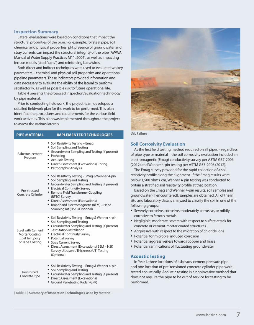
LVL failure

WaTeRscapes | fall 2012
[ figure 2 ] Electrical Continuity Test
[ figure 1 ] Wenner 4-Pin Test
P1
C1
P2
C2
NULL
OHMS
RESISTANCE METER
d dd
d
C1 P1 P2 C2
C U R R E N T L I N E
EQU I POT ENT I AL
SU
RFA
CE
mVDC
ADC
+-
DC POWERSOURCE
VARIABLERESISTOR
AMMETER
VOLTMETER
[ pipeline condition assessment ]
sensors are attached to the lateral at access points (valve vaults, aVaR/Bo installations) or thru “potholes” constructed to the top of the pipe. initial evaluation uses 300- to 700-foot-long sections. if necessary, a higher resolution can be obtained by moving the acoustic sensors closer together.
one leak was identified in a 24-inch asbestos-cement lateral, which identified the soil as being predominately moderately- corrosive but can subject the pipe to severe sulfate attacks. Recently, after obtaining permissions and during a planned outage, it was
later determined that a leak did not exist. a sample of the pipe was obtained to estimate the remaining competent wall thickness to better evaluate its remaining service life. Results of this effort are still pending.
electrical Continuitya test for the state of the electrical continuity along metallic
and pre-stressed concrete cylinder pipelines was completed to validate the installed condition (based on available design drawings, as-constructed documentation and shop drawings). electrical
continuity testing is conducted along entire lateral alignments where rubber gasketed joints or non-circumferentially welded pipeline specials exist, where feasible. The testing hinges on adequate access to pipeline appurtenances such as blow-offs and air vacuum/air release valves, pumping and monitoring facilities, and test stations.
This testing is completed prior to implementing a close-interval survey (cis). During the Years i and ii evaluations, additional test stations were installed to facilitate the electrical continuity evaluation and identify potentially harmful unknown electrical current flowing on the pipeline and its direction of movement. further continuity testing confirmed that some pipes were electrically discontinuous requiring repair for proper operation of a corrosion mitigation system.
an electrically continuous pipe is required for cathodic protection (cp). if cp is not installed (and operating), the lateral is susceptible to long-line corrosion cell as a function of soil parameters.
Pipe Potential SurveyBaseline potential testing was conducted to
establish baseline conditions on metallic and pre-stressed concrete cylinder laterals to monitor future changes. comparing potentials over time helps estimate the probability that corrosion is occurring and evaluate the status of the corrosion mitigation system, if installed.
Depending on how the lateral has been identified – electrically continuous or discontinuous – the close-interval survey methodology is determined and conducted. The cis identifies anodic areas where the pipe is likely experiencing corrosion and helps to identify locations of possible stray current discharge points.
8

Diameter
96, 90 pccp steel – mortar lines and coated
soil corrosivity – severe corrosion potential; high sulfates one location – indicates potential for severe sulfate attack; nine test stations installed; future inspection recommended
24, 24asbestos
steel – coal tar enamel lined
asbestos – internal leeching suspected based on water quality; recommendation ac pipe coring and petrographic analysis
steel – Two test stations installed, pipe in good condition, cathodic protection system recommended
16 asbestos soil corrosivity – severe corrosion potential; internal water quality – corrosive; approach for all ac pipes,
24 asbestos soil corrosivity – moderately corrosive; internal water quality – moderately corrosive; acoustic monitoring – leak identified; approach for all ac pipes
48 pre-tensioned ccp soil corrosivity – severely corrosive; potential survey results for partial pipe only, recommended to wait and perform testing on entire alignment in Year ii work
96, 108 pccp class iii wire, two bonding straps, shorting rods to steel can, internal Z joint bonds; recommendation to install electrical insulating device, design stray current mitigation system
96 pre-tensioned ccpclass ii wire, no bonding straps, no shorting rods to steel can, no joint bonds; ppic (pURe) re-evaluated 2004 data using current analysis tool and wire breaks were significantly reduced; recommended to reinspect in the future.
120 Rcpsoil corrosivity – mildly corrosive except at land/water interface area along lake Mead; direct assessment with gpR survey at four locations indicates small degradation of reinforcing steel, but not significant; reinspect at future date.
[ table 5 ] Results and Recommendations for year i Laterals
internal PCCP inspectioninternal inspections using remote field eddy current/transformer
coupling (Rfec/Tc) were previously completed by ppic (now pURe Technologies) to help evaluate the pccp alignments. Different internal inspection tools are currently available, and the selection of one over the other is a function of access, pipe size, hydraulic pressures and velocities.
This equipment is placed in the pipe and creates an electromagnetic field with a transmitter and monitors secondary fields with the receiver while traveling the length of the pipe. if there are any breaks in the wire in the pccp section, the resulting electromagnetic field signature is detected and correlated to pipeline stationing.
Two laterals in the project were previously inspected by ppic and the results of these inspections were used when evaluating the Main aqueducts a and B. Because of safety concerns for pipe entry, large costs associated with the pipe section rehabilitation – and advancements in ppic’s evaluation algorithms – the data was re-evaluated and pipe that was previously identified as potentially severely distressed was reduced to having minimal wire breaks that only required future monitoring.
Direct AssessmentBased on the results of the indirect pipeline inspection (soil
corrosivity, acoustic testing, electrical continuity and potentials), locations exhibiting a high potential for deterioration or corrosion were identified for an additional investigation or direct assessment.
after excavation of pipe at the identified location, a direct assessment was made using methodologies based on the pipe material:•asbestos – core sampling, petrographic analysis • steel – Broadband electromagnetic (BeM), Ultrasonic testing (UT)
(optional) • pccp – BeM, UT (optional) • Rcp – ground penetrating Radar
asbestos – one site was identified for direct assessment where acoustic testing indicated a potential leak site and was expected that the pipe would need to be replaced. although not performed, petrographic analysis, in addition to the acoustic testing, is available to help determine the health of acp. petrographic analysis provides material characterization analysis by using a combination of optical microscopy, scanning electron microscopy, and chemical analysis. petrographic analysis, from geology meaning “the systematic
9www.hdrinc.com

WaTeRscapes | fall 2012
[ pipeline condition assessment ]
characterization of rocks in hand specimen and thin section,” provides information about the failure mechanism.
steel – if a steel pipe with a cement-mortar coating is subjected to a direct assessment, the pipe is excavated to the pipe’s spring line and its steel wall thickness measured to determine the loss of steel. previous work on the las Vegas Valley lateral has shown that the use of broadband electromagnetic (BeM) equipment over the entire exposed surface of the lateral provided a good assessment of the average wall thickness of the pipe.
if BeM was used, a hand scanning kit (HsK) was used with data analysis turnaround provided by the equipment manufacturer within 24 hours. it was decided to use the HsK as a screening tool and prior to removal of the cement-mortar coatings and perform UT testing in areas indicated by the HsK where significant thinning of the wall or a pin hole was developing.
The use of HsK is considered non-destructive because it does not generally require removal of the protective coating, scanning through coatings such as mortar (up to approximately 3 inches or 76.2 mm), paint and tar. The HsK system is generally considered accurate to within ±40 mils (0.040 inches or 1.016 mm) and requires data processing using a multi stage screening and processing procedure.
Ultrasonic thickness (Ut) testing – UT results are significantly more precise than HsK, but the measurements are limited to a test window where the mortar has been removed to expose the steel pipe and identify an area with the highest probability of corrosion.
UT testing is technically considered non-destructive because it does not harm the steel pipe wall, but does require the removal of pipe’s protective cement-mortar coating to allow the transducer to contact the pipe’s steel can.
LVL Coupon failure
During UT testing, samples of the mortar coating are taken for chemical testing. if chloride concentrations are sufficient enough to overcome the alkalinity of the cement paste’s pH, chloride ion can create a highly localized attack or pitting. corrosion of the steel may also occur when the pH of the cement-mortar is insufficient to passivate the steel can.
Ground-Penetrating Radar (GPR)When soil corrosivity testing indicates a corrosive
condition adjacent to a reinforced concrete pipe (Rcp), a direct assessment is conducted. gpR can detect subsurface voids (delaminations) within concrete pipes and structures.
gpR radiates short pulses of high-frequency electromagnetic (eM) energy into the pipe’s surface from a transmitting antenna. This eM wave propagates into the concrete at a velocity that is related to the electrical properties of subsurface materials (specifically, the material’s relative dielectric permittivity).
When this wave encounters the interface of two materials having different dielectric properties (i.e., voids or delamination), a portion of the energy
is reflected back to the surface, where it is detected by a receiver antenna and transmitted to a control unit for processing and display.
Resultsan example of some of the results from the Year 1 evaluation are
presented in Table 5 (on page 9).
Conclusioninspection and evaluation of existing underground infrastructure
requires the understanding and application of available technology for correctly interpreting the information, access to existing design, construction and shop data, and a willingness to look at results with openness to accept the results.
as an example, based on preliminary results from Years i and ii, work on the Year iii laterals investigation was modified and expanded – modified to conduct an enhanced cp survey of the condition of existing facilities, and expanded to include all remaining laterals not identified in the criticality evaluation and constructed after the 2000 cutoff.
for this project, each lateral examined in the first two years of the project has its own separate report, providing available information about the lateral, including all test results and measurements, and a discussion of results, including deficiencies and concerns. The report then provides possible courses of action to mitigate or correct problems, including a range of planning level cost estimates.
For additional information about this article, please contact Scott Christensen at [email protected] , or Steven Fox at [email protected] .
10

[ treatment facility condition assessment ]
ThE fLoREnCE WATER TREATMEnT PLAnT, located in northeast omaha, neb. is the oldest water treatment facility in the Metropolitan Utility District (MUD) system with components dating back to 1889. located along the Missouri River, the plant has a maximum day capacity of approximately 158 mgd.
concerns with the water treatment plant age and condition, along with increasingly stringent regulatory requirements, were the driving forces for this comprehensive condition assessment and evaluation project.
MUD retained HDR to conduct a comprehensive engineering review for the florence Water Treatment plant (WTp) to form a master plan for the facility. This master plan provided general project descriptions and the associated costs for incorporation into the capital improvements plan for MUD.
The major components of the comprehensive engineering review
coMpReHensiVe engineeRing ReVieW for Metropolitan Utilities District’s Florence Water Treatment Plant
included the consideration and evaluation of the following:•Multi-disciplined detailed assessment of
all existing structures and equipment at the water treatment plant
•Detailed review of the capacity of all individual treatment units to determine the facility limitations and constraints
•Hydraulic model of plant capacity including a survey of key water elevations to calibrate the model
• evaluation of water demands to determine the capacity requirements and staging of facility improvements projects
•comprehensive review of raw water quality, finished water quality goals and sDWa compliance issues
•Development of concepts/alternatives to upgrade the individual treatment units to restore the condition of existing units, improve treatment capability for regulatory compliance and expand existing capability as required for desired capacity
• completion of a detailed phasing plan to implement the improvements taking into consideration MUD’s regulatory requirements, condition of facilities, facility expansion and treatment requirements, and financial constraintsone of the first steps of the review
was to conduct a condition assessment of the existing facility components. This assessment included architectural, structural, mechanical, electrical, instrumentation and process reviews of each of the facility components to identify deficiencies or needed improvements for the existing facility components.
condition assessment forms were completed for each treatment process, equipment and structure at the WTp. interviews with plant operating and maintenance staff, review of equipment maintenance logs and review of past reports of the facility were completed for the condition assessment.
(continued on back cover)
By Glenn Dostal, P.E., Senior Vice President, Omaha, Neb.
11www.hdrinc.com

waterscapes | fall 2012
[ reservoir and pump station assessments ]
ThE CiTy of SCoTTSDALE, ariz., is home to a vibrant year-round golfing industry. numerous public and private courses attract players from around the world. from a water engineering perspective, the challenge of maintaining this industry in a desert environment is to avoid use of potable water for irrigation.
approximately 22 years ago, the city of scottsdale (city) decided to implement a reclaimed water system so that the local golf industry could continue to expand without consuming precious potable water sources.
The planned system, called the Reclaimed Water Distribution system (RWDs), was designed to provide up to 1 million gallons per day (mgd) of irrigation water per golf course for as many as 20 golf courses. The planned 20 mgd system comprised the following major facilities as depicted in figure 1:•Water campus Water Reclamation plant (WRp)
• Reservoir “B”• pump station cap (ps95)• Reservoir “a”• pump station “a” (ps96)• pump station “B” (ps97)• pump station “c” (ps98)• Reservoir “D”• pump station “D” (ps99)
in addition to these facilities, there are over 14.3 miles of transmission lines (trunk lines) and 11.8 miles of branch lines (main lines) to convey water to the 20 golf courses. There are three inline RWDs stations (ps96, ps97 and ps98) and no appreciable storage within the system.
The RWDs design (not including Water campus WRp) was completed in 1991, and system operation commenced in 1993.
cit y of Scot tSDAle
[ from left ] Photograph 1. Leaking APS Transformer at RWDS PS96; Metals, Photograph 2. Connections and fitting at the Pump Discharge Pipe to ARV
Reclaimed Water Distribution System (RWDS) Evaluation, Condition Assessment and Conceptual Design improvementsBy Ed Junod, Senior Project Manager, Phoenix
12

scottsdale’s Water campus WRp – and its associated sewage pumpBack system – was the planned source of reclaimed water and did not come online until 1998.
from 1993 until 1998, the sole source of RWDs supply was water taken from the central arizona project (cap) canal, and pumped northward by ps95 to Reservoir “a”. since 1998, RWDs is supplied with a blend of cap canal water and product water (tertiary effluent and/or advanced water treatment (aWT) water) derived from Water campus WRp.
after nearly 20 years of operation, RWDs is still able to provide its maximum design pumping rate. But it has become challenging to manage and control due to the early adjustment of the final location of a number of golf courses from one pumping zone to another pumping zone, frequency of reclaimed water orders, the aging infrastructure and complexity of the system.
Though the full-range of irrigation water demands are being met, the system is doing so with a smaller margin of safety. RWDs was designed to deliver maximum demands with at least one standby pump at each pump station. There is currently no redundancy in the system.
city officials retained HDR in June 2011 to evaluate the condition of the RWDs and to recommend the improvements needed to restore the original degree of system reliability and capability.
RWDS Condition Assessmentin July 2011, HDR conducted a “triage,” or abbreviated condition
assessment of all the pump stations in the RWDs to assess the current condition and performance of the system. a secondary objective was to discover potential operational improvements that were identified by HDR’s use of the infoWater hydraulic model.
To set a baseline of RWDs conditions and performance, previous evaluations and reports were reviewed by the study team. These reports assigned a condition rating and an estimated remaining useful life to the systems and their components. The ratings were based on visual inspection and interviews with operations and maintenance staff.
in addition, assets were assigned a level of “criticality” based on the consequence of failure such as effects to public health and safety, environmental impacts, cost of repairs and effects on customers. neither performance testing nor non-destructive testing was conducted on the RWDs in any of the previous reports.
To assess the existing RWDs condition, HDR performed a number of activities, including:•conducting interviews with city and golf course officials to
identify the historical problems they were facing, including RWDs operating characteristics that are good, bad or in need of improvement
• Reviewing previously performed condition assessment reports• Reviewing and analyzing city-conducted RWDs deadhead/shut-
off/efficiency tests
• conducting “triage” condition assessments of RWDs components• performing an evaluation of the city’s existing infoWater hydraulic
model, then updating that model so it could accurately predict system performance
• conducting a land survey to confirm the horizontal and vertical location of all major system features
•assisting the city’s job order contracting (Joc) services to identify system valve and appurtenance conditions; calibration of field instruments and field performance testinga significant observation was that the RWDs ps96 utility
transformer appeared to have internal damage and subsequent leakage, as shown in photograph 1. This finding was communicated to city staff as well as the arizona public service (aps).
The possible internal damage and apparent leak can be attributed to transformer overloading that takes place during golf course over seeding operations. loss of this transformer would completely shut down the RWDs.
other significant observations included:• identification of multiple dissimilar metals connections and
fittings at the surge tanks and the pump discharge pipe to aRVs; brass, steel and galvanized fittings were used. This combination of dissimilar metals will accelerate the rate of corrosion. an example of this corrosion is shown in photograph 2.
• surface corrosion on numerous ps discharge spools as they enter the concrete pump slab, as shown in photograph 3 on page 15
RWDS Performance Testingcity staff conducts individual pump performance testing
approximately every two years. This test measures the pumping flow rate, total dynamic head, voltage and amperage to calculate overall efficiency. The test results identify which pumps have excessively worn impellers and are in need of overhaul.
several pumps and motors throughout the system have been rehabilitated based on the test results or upon failure. Because the previous reports and assessments were fairly recent and city staff had conducted a recent individual pump performance test (nov. 30, 2009), HDR’s approach involved testing the performance of the entire system in operational modes that mimic actual system performance requirements. This type of testing would be more useful for identifying system deficiencies; rather than duplicating previous assessments that were focused on individual pump performance.
HDR conducted a system-wide performance test of the RWDs pump stations 96 through 99 over two consecutive days in December 2011. The purpose of the performance (flow) test was to demonstrate system performance and to verify the accuracy of the infoWater model to predict system performance.
The field performance test was conducted based on test protocol developed by the HDR condition assessment/operations group. pump shut-off head testing was not conducted during
13www.hdrinc.com

waterscapes | fall 2012
[ figure 1 ] facility overview
the performance test as originally proposed, because the city had already done this in october 2011.
The December 2011 performance test confirmed several operational limitations and also indicated operational changes that could be put into effect immediately. The emphasis of the flow test was confirmation of system performance, as opposed to individual pump performance (the focus of the city’s bi-annual performance tests). in addition to confirming system performance under controlled operating scenarios, the system test also provided data useful for final calibration of the infoWater hydraulic model.
confidence in the hydraulic model allowed for better analysis of potential improvements such as increasing pump motor horsepower, adding VfDs, expanding Reservoir “D” capacity and other improvements. The hydraulic analyses also showed that increasing the pump motor horsepower at ps96 will result in an
increase of the hydraulic grade line (Hgl) of the trunk line.
as a direct result, this provided the required redundant pumps at RWDs pump stations 96 through 98 without adding any new pumping equipment or gear.
The system was tested in three operating scenarios – low, medium and high demand. RWDs ps99 also was tested with varying site turnout demand flows and system pressures to demonstrate that station’s operating capacity at varying discharge pressure set points.
as part of the performance test, power transducers were installed at service entrance sections at RWDs pump stations 96 through 99.
The power transducers were connected to power quality analyzers and data was recorded at one minute intervals during the test. Data recorded included voltage, current,
apparent power, real power, power factor and frequency.The power data was analyzed and graphs were generated for each
pump station that illustrates power consumed in kilowatts (KW) vs. pump start times. also, a KW/gallon efficiency graph was generated for each pump station to illustrate the efficiency of each during the test with respect to the total number of pumps running.
RWDS Proposed improvements a three-phase improvement program was recommended to
restore the RWDs to a reliable level of service and maintain its design maximum pumping capacity. as part of the condition assessment report, a listing of the recommended improvements was provided.
additional descriptions, discussions, engineering background, etc., of each recommended improvement phase was provided in a follow-up report titled, “RWDs improvement Recommendations.”
RWDS PS99 (D)5.8 MGD
RWDS PS98 (C)12.35 MGD
RWDS PS97 (B)14.0 MGD
Site 130
CAP1
IWDSSite 130B
RWDSPS95 (CAP)20.0 MGD
RWDS PS96 (A)18.0 MGD
Water CampusWRP E�uent
Res D
Res A
CAP Canal
Res B
[ key ] * Golf Course
*Mirabel*Legend Trail*Desert Mountain
5.8 MGD Total
Raw waterto CAP WTP
*Troon North*Estancia*Terravita*Boulders North & South*Whisper Rock Upper/Lower
6.6 MGD Total
To IrrigationWater DistributionSystem (IWDS)
*DC Ranch*Silver Leaf*Grayhawk: Talon & Raptor
4 MGD Total
*Troon East*Desert Highland
1.65 MGD Total
[ reservoir and pump station assessments ]
14

The following is a brief description of each of the recommended improvement phases:
Phase 1 immediate improvements – Those urgently required to reliably provide the maximum pumping capacity for summer 2012. peak pumping requirements can be met with the existing system. However, pump performance has deteriorated to such an extent that there are no standby pumps available during maximum demand conditions. Thus, failure of a single pump can diminish overall pumping capacity.
The proposed phase 1 improvements entail replacement of 18 of 29 pumping units (for RWDs pump stations 96 thru 99). This limited replacement of pumps is consistent with the immediately available budget and schedule (January to May 2012).
Phase 2 short-term improvements – These are intended to complete the replacement of remaining pumps (for RWDs pump stations 96 through 99), as well as address other system shortcomings. it is recommended that these improvements be implemented by summer 2013. once implemented, the short-term improvements will simplify system control and strengthen the system’s overall ability to meet maximum demands by eliminating unnecessary headloss at certain golf course turnouts.
Recommendations also will be made to system control pressure setpoints to further increase system capacity and reduce pump energy costs. The one-year window to implement this program will allow time for required engineering design services and to obtain approval of the improvement budget from the RWDs golf course participants and the city.
Phase 3 long-term improvements – These entail replacement of specific pump station features to further enhance system reliability. some of these improvements will be done under the city’s maintenance contract (Joc), such as:• Trunk line and main line valve replacement• electrical panel inspections and repairs/replacement•Magnetic flow meter replacement at RWDs pump stations
95 and 99• Various electrical improvements•addition of second VfDs to RWDs pump stations 97 and 98
only one VfD is required for proper system operation and control. However, without an installed second (i.e., standby) VfD at those stations, VfD failure precludes maintaining setpoint pumping rates.
ConclusionsThe city of scottsdale’s Reclaimed Water Distribution system
was assessed for its overall condition and production capacity. The condition assessment included review of prior work conducted on the system, and investigations, field activities and hydraulic modeling conducted by HDR over the past several months.
Due to its age (20 years) and the deterioration of identified system components (aged pumps, valves, electrical gear and scaDa), the system was found to be marginally capable of meeting seasonal
high demands. There currently is no redundancy in the system and several components were identified that, if any of them failed, could prevent the system from meeting full contracted customer deliveries.
a three-phase improvement program was recommended to restore the RWDs to a reliable level of service and maintain its design maximum pumping capacity. The immediate improvements identified in the condition assessment report are underway and will improve the system’s ability to meet summer 2012 demands. The short- and long-term improvements will restore the system’s original design capacity and provide pumping redundancy while also improving system reliability, along with operational efficiency and flexibility.
Though the improvement recommendations proposed by HDR were intended to occur over the next few years, in reality, RWDs operational and maintenance budget constraints dictate that both the short- and long-term improvements to the RWDs be spread over a longer period. HDR and city officials will be conducting a workshop to prioritize the improvements and customize an improvement schedule to match the anticipated RWDs budget.
For more information about this article, please contact Ed Junod at [email protected] .
Photograph 3. Corrosion on the Discharge Spool as it Enters the Concrete Slab
15www.hdrinc.com

waterscapes | fall 2012
[ sewer system assessment & rehabilitation ]
in MARCh 2008, the Beaufort-Jasper Water and sewer authority (BJWsa) won a contract with the naval facilities engineering command (naVfac) southeast to operate and maintain the water distribution and the wastewater collection and treatment systems serving the Marine corps air station and naval Hospital in Beaufort, s.c., the laurel Bay Housing area, and the Marine corps Recruiting station in parris island, s.c., for the next 50 years.
This project, part of the Utility system privatization program, was a major endeavor for BJWsa and represented a significant expansion of their service area. However, the entire sewer system for the laurel Bay Housing area, which comprises the largest portion of the collection system, had been almost entirely rehabilitated in 1995-96. so what could possibly go wrong?
shortly after taking over the utility systems, BJWsa officials had to begin dealing with numerous sanitary sewer overflows. operations and maintenance requirements were much higher than anticipated, and the problems encountered were more indicative of a sewer system in serious disrepair than one that had been rehabilitated. so BJWsa conducted a pilot condition assessment study to see what issues could be identified.
The results were alarming.Major failures of the liners installed in
the sewers to correct previous problems were observed. Defects noted included buckled liners (hot dogging), as shown in figure 1, areas where the liner had torn away from the laterals and places where it looked like the liner had actually melted (see figure 2). similar defects were observed throughout the pilot study area.
in november 2010, BJWsa officials issued a request for proposals to perform a comprehensive sanitary sewer condition assessment of the laurel Bay Housing collection system and to develop a recommended improvement program. The laurel Bay collection system serves 1,405 military housing residences and one school, and consists of approximately 79,500 linear feet of sanitary sewer lines ranging in size from 8 to 30 inches and 320 manholes (see Map 1 on page 18).
HDR’s proposal team blended with experienced sewer assessment and rehabilitation staff in Walnut creek, calif., and las Vegas, nev.
This team presented a project approach that was thorough, inclusive of BJWsa’s engineering and o&M staff, and cost-effective.
Condition AssessmentThe first thing the project team needed
to do was find out what was going on inside the pipelines. ccTV was used to observe, identify, and quantify defects in the sewer pipelines. an important component of HDR’s approach was to use a recognized reference standard for completing the ccTV inspection and recording and evaluating all observed defects.
The national association of sewer service companies (nassco) pipeline assessment and certification program (pacp) is a standardized observation and defect coding system that met these requirements. The use of a standardized defect coding system allows the inspection to be completed in a defensible and repeatable manner.
The nassco defect codes are divided into four primary categories:• structural defects that are used to note
structural deficiencies that have occurred within the pipe due to use, such as cracks
•operational and maintenance defects that are used to note observations pertaining to issues with operation and maintenance of the sewer mains
• construction features that are used to note service connections and other items such as location of manholes
in South cArolinA
By Kent Von Aspern, Northern California Pump Stations/Pipeline Lead, Walnut Creek, Calif. Tracy Lewis, Senior Project Manager, North Charleston, S.C. Walt Fletcher, Environmental Engineer, North Charleston, S.C.
Rehabbinga Rehab
16

Liner Creep and Tear: In this failure, the liner pipe has slipped and the material has failed at a lateral. This type of failure is caused by an inappropriate lateral reconnection method, failure to stop infiltra-tion, lack of an end seal at the upstream manhole, and substandard liner thickness.
Ridge Line Failure at Crown: Typically caused by failure to achieve cure temperature of at least 235⁰F and/or cooling cycle pressure of 33 psig.
Missing End Seal: Lack of an end seal at the manholes allows wastewater to enter the annular space between the host pipe and the new liner.
[ figure 1 ]
Liner Structural Failure: Caused by infiltration through host pipe and substandard liner thickness.
[ figure 3 ]
Top of Pipe Failure: Unlike the ridge line failure at the crown, this failure is typically caused by hydrostatic pressure from groundwater entering through leaks in the host pipe exceeding the structural capacity of the liner.
[ figure 4 ]
[ figure 2 ]
[ figure 5 ]
oBservation DeFeCt CoDe DeFinition no. oF
oBservationsstructural Defectsx
LFBK Lining Failure – Buckled Lining 1,078
LFDE Lining Failure – Defective End 286
LFW / LFB Lining Failure – Wrinkled Lining, Blistered Lining 163
LFCS / LFOC / LFUC Lining Failure – Service Cut Shifted / Overcut Service / Undercut Service 92
LFBU Lining Failure – Bulges 56
LFPH Lining Failure – Pinholes 44
LFZ Lining Failure – Other 27
LFAS Lining Failure – Annual Space 25
RPR / RPRD Pipe Replaced /Pipe Replaced Defective 21
B / BSV / BVV Broken Pipe / with Soil Visible / with Void Visible 17
JOL / JOM Joint Offset – Large / Medium 17
LFAC Lining Failure – Abandoned Connection 13
H / HSV / HVV Hole in Pipe / with Soil Visible / with Void Visible 13
LFD / LFDL Lining Failure – Detached Lining / Delamination 10
CL Longitudinal Crack 10
D Deformed 6
CC Circumferential Cracks 5
WFC Circumferential Weld Failure 4
FL / FS Fracture Longitudinal / Fracture Spiral 3
XP Pipe Collapse 2
RPPD Point Repair – Patch Repair, Defective 2
CM Multiple Cracks 1
operation and maintenance Defects
I-D / G / R / S / W Infiltration – Dripper / Gusher / Runner /Stain / Weeper 188
DA-E / GS / Z Deposits Attached – Encrustation / Grease / Other 173
RFB / C / J / L Roots Fine – Barrel, Connection / Joint / Lateral 74
RBB / C / J / L Roots Ball – Barrel / Connection / Joint / Lateral 35
RMC / J / L Roots Medium – Connection / Joint / Lateral 30
DS-F / Z Deposits Settled – Fine / Other 10
OBR / Z Obstruction – Rocks / Other 7
RTC / J / L Roots Tap – Connection / Joint / Lateral 6
VC / VZ Vermin – Cockroach / Other 5
Construction Features
TRI Tap – Rehabilitated Intruding 27
TBD/ I Tap Break In – Defective / Intruding 26
TFC / D / I Tap Factor Made – Capped / Defective / Intruding 15
LD / L / RD / U Line Down / Left / Right Down / Up 8
ISSR / L Intruding Sealing Ring / Loose 2
miscellaneous Features
MWLS Miscellaneous Water Level Sag 151
MCU Camera Underwater 66
[ table 1 ] CCTV inspection Data Summary
17www.hdrinc.com

waterscapes | fall 2012
ccTV inspection was completed for about 90 percent of the sewers. obstructions in the pipes and “lost” manholes made it impossible to inspect the remaining portion of the sewer system, so an automated system was developed.
This automated system was adapted to meet the specific requirements of the laurel Bay project, resulting in a very consistent and cost-effective analysis of defects. The observed defects are listed in Table 1. clearly, the most frequent source of defects was associated with failures of the previous attempts at rehabilitating the collection system.
understanding the Problemsnow that we had a catalog of defects,
the next thing the project team needed to do was explain how those defects had occurred. it was considered important to understand how the failures had occurred before attempting to identify improvements. Unfortunately, there were no records of the previous rehabilitation projects. from the ccTV inspection, however, the project team identified three methods of rehabilitation:1. Fold-and-form lining – involves heating
a polyethylene pipe and deforming the
pipe into a “U” or “c” shape so that it can be inserted into an existing pipeline. after the deformed pipe is inserted into the host pipe, hot air or hot water is introduced into the deformed pipe to heat and expand the pipe to its original shape. The reformed pipe should fit tightly against the host pipe, but there is no mechanical bonding between the new and old pipes. laterals must be reinstated by cutting holes in the new pipe at appropriate locations.
2. roll-down lining – involves mechanical compressing of a polyethylene pipe using a series of dies and rollers. The temporarily smaller pipe is inserted into the host pipe and soon relaxes to its original size, expanding to fit tightly against the host pipe. as with fold-and-form, there is not a mechanical bond between the new and old pipes, and laterals are reconnected by cutting holes in the polyethylene.
3. Cured-in-place pipe (CiPP) lining – involves insertion of a soft epoxy or polyester resin liner into a host pipe, then inflating and curing the liner with hot water or hot air. The heat initiates an exothermic reaction that hardens the resin, creating a new pipe inside the old pipe. Unlike the previous methods, the cipp liner is mechanically bonded to the host pipe. laterals are reinstated by cutting holes in the new pipe.
in general, it was found that the pipelines rehabilitated using the roll-down method or cipp were in good shape. There were several characteristics of these methods that appear to have led to the more successful result. each seemed to be designed as a full structural replacement for the sewer, which resulted (especially in the case of the roll-down pipe) in a thicker pipe.
another key feature of these methods was the reinstatement of the laterals. for the roll-down and cipp methods, the laterals were reinstated using external means, with positive reconnections made between the lateral pipe and the new sewer.
failures were largely concentrated in the sewers that had been rehabilitated using the fold-and-form system. These failures were attributed to the following.
[ map 1 ] System Map
[ map 2 ] Recommended improvements Map
[ sewer system assessment & rehabilitation ]
18

Hot-dogging – so named because of a tendency for the liner to return to the deformed “U” shape of a hot dog bun – was thought to occur due to two possible circumstances. When the deformation was at the top of the pipe, it was considered likely that the cause was improper installation techniques. Heating the pipe to a temperature of 235°f and holding the pressure above 33 psig for an appropriate length of time is required to “reset” the round shape of the pipe.
failure to follow these directions can create a propensity for liner failure. Hot-dogging at the top of the pipe was thought to be related to improper installation because this is the orientation of the “U” shape when inserted into the host pipe.
Deformations at locations other than the top of the pipe, shown in figures 3 and 4 (on page 17), were thought to be related to another cause – improper design. High groundwater conditions produce large hydrostatic forces on the liner when the host pipe has many leaks – a common situation that would lead to rehabilitation.
if the liner is too thin the hydrostatic forces can overcome the structural capacity of the new pipe, leading to failures. since thin liners were easier to deform, easier to reform and less expensive, in cases where the client was not familiar with proper design contractor’s often tried to get away with the thinnest liner possible.
other common defects observed involved damaged laterals and situations where the plastic liner appeared to be melted (see figure 2). These defects were found to be the result of design defects. in the original rehabilitation project, laterals were not reinstated externally by installation of a tee connection.
in addition, end seals were not installed at the manholes (end of each liner segment), as seen in figure 5. These conditions, along with active infiltration through the host pipe, allowed groundwater to enter the annular space between the old and new pipes.
groundwater and wastewater in the annular space served as a lubricant, resulting in the liner being pushed
[ table 2 ] Sewer Main Rehabilitation Recommendations Summary
downstream and displacing and tearing the liner. for comparison, external lateral reconnections were installed in the segments rehabilitated using the roll-down method. These segments did not exhibit these defects.
fixing the Collection Systemnow that the project team had conducted
a comprehensive internal inspection program and developed an understanding of the causes of the defects, the next step was to develop a prioritized improvement plan to restore the collection system to a serviceable condition.
The project team used an approach for evaluating sewer defects that had been used on other HDR projects in las Vegas, northern california and other locations around the country. This approach is based on categorizing the types and severity of defects in each sewer segment, then analyzing the key features of each sewer segment as they impact various rehabilitation/replacement construction methods. This results in determination of the most likely method of rehabilitation and prioritization of improvements. The analysis can be automated for efficient evaluation.
for the laurel Bay sewer system, the previous rehabilitation complicated the development of the improvement plan. for example, pipebursting is a common and cost-effective method to replace a deteriorated sewer. To pipe-burst a sewer with a polyethylene liner in it, the liner needs to be sliced at the quarter points first. This additional step increases the cost of the method.
The project team also used its understanding of the liner failures to, where possible, leverage the previous rehabilitation. if the previous liner had not
rehaB / rePair methoD
no. oF sewer mains
total lenGth (lF)
open cut Replacement 113 29,736
pipe Bursting 56 15,159
point / spot Repair 35 700*
install / Repair end seals 113 –
Reestablish lateral(s) 25 –
Heavy clean; Reinspect 3 999
Root removal 1 –
Maintain 25 4,134
slipped or buckled, then in many cases the appropriate improvement recommended included reconnecting the laterals and installing end seals to prevent wastewater from entering the annular space.
These minor improvements could extend the life of the previous rehabilitation. The recommended improvements are summarized in Table 2 and pictured in Map 2 on page 18.
These improvements, to be implemented over a 10-year period, were assigned an estimated total program cost of just over $4.7 million.
Lessons LearnedHere are some of the most important
lessons learned through completion of the laurel Bay gravity sewer evaluation project:1. not all rehabilitations are created equal2. a poorly implemented rehabilitation
program can create more problems than it solves
3. The approach to evaluating sewer defects produced a highly technical projection of recommended improvements in an efficient manner
For more information about this article, please contact Kent Von Aspern at [email protected] , Tracy Lewis at [email protected] , or Walt Fletcher at [email protected] .
19www.hdrinc.com
waterscapes | fall 2012
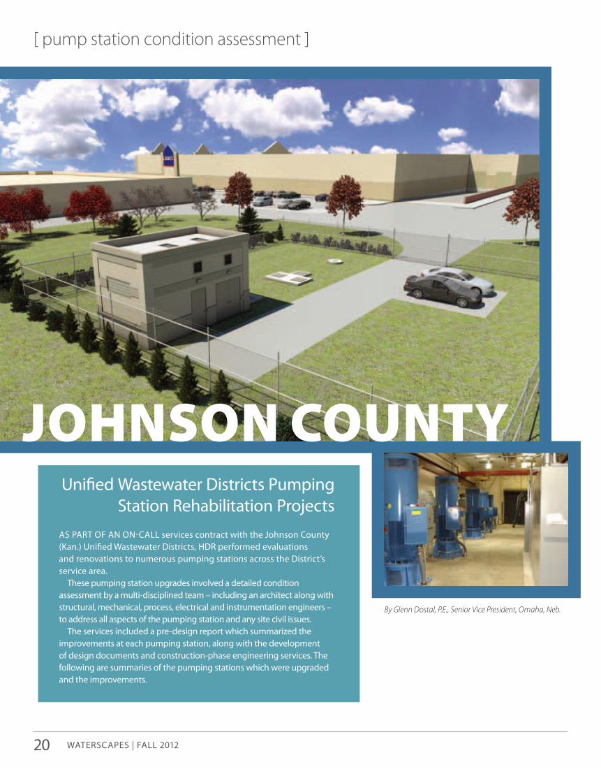
[ pump station condition assessment ]
Unified Wastewater Districts pumping station Rehabilitation projects
Johnson County
as paRT of an on-call services contract with the Johnson county (Kan.) Unified Wastewater Districts, HDR performed evaluations and renovations to numerous pumping stations across the District’s service area.
These pumping station upgrades involved a detailed condition assessment by a multi-disciplined team – including an architect along with structural, mechanical, process, electrical and instrumentation engineers – to address all aspects of the pumping station and any site civil issues.
The services included a pre-design report which summarized the improvements at each pumping station, along with the development of design documents and construction-phase engineering services. The following are summaries of the pumping stations which were upgraded and the improvements.
By Glenn Dostal, P.E., Senior Vice President, Omaha, Neb.
20

Rock Creek Pumping StationThis key pumping station is located at the crossroads of major
streets on a congested site. The upgrade included the replacement of the existing pumps with dry pit submersible pumps and a firm capacity of 12 mgd.
Variable frequency drives were included on two pumps to minimize previous problems with frequent starts due to the varying flow conditions experienced at the station. an electrical room was constructed to reduce heat and corrosion issues for the electrical equipment. all electrical and mechanical equipment was upgraded to comply with nfpa 820, which also required a new separate ingress/egress to the station.
The main power feed was upgraded to a 1,000 amp service, and a second power supply was provided for backup power. new interior and exterior lighting was installed, all handrails/guardrails were upgraded to comply with uniform building code, and all exposed metals were cleaned and repainted.
There also was work done to the existing carbon scrubber, including:• Relocation and upgrading for odor control• piping and valves replaced as required• Repairs to leaking wall penetrations•a new trench drain was provided with concrete infill in the pump
gallery to improve drainage and simplify maintenanceall of the work needed to be carefully sequenced to limit
shutdowns, yet stay functional to address the pumping requirements for both dry and wet weather.
Brush Creek Pumping StationThis pumping station project involved a similar renovation, as
well as an upgrade to an upstream wet weather holding station. system back-ups were an issue due to management of the wet weather flows and station reliability. Maintenance requirements were becoming increasingly problematic for most of the mechanical equipment.
existing screens were replaced with a grinder for dry weather flow and a new mechanically-cleaned screen for wet weather flows. existing sluice gates needed to be replaced in the pump station and diversion structure. a modification in the diversion structure was incorporated to improve and simplify the flow diversion to the holding station.
The control system for management of the excess flows was upgraded with additional level monitors and operating options to reduce system back-ups. Miscellaneous architectural and mechanical improvements were incorporated to address code issues and any deteriorated materials or equipment.
Dykes Branch Pumping StationThis station was badly deteriorated and required an extensive
rehabilitation effort. The station had a capacity of 1.4 mgd for dry weather and 4.5 mgd for wet weather. following a detailed evaluation by a multi-disciplined team, a complete renovation of the station was performed.
Replacement of the pumps, piping, valves, and bar screen/trash rack upgraded all of the process equipment. electrical motor control centers, instrumentation and lighting were upgraded. There also was a complete upgrade to the HVac systems.
Doors and roofing were replaced or upgraded, the exterior masonry was renovated, and the station was repainted. exterior civil site issues were addressed to improve access for materials handling and maintenance staff. careful sequencing of the improvements was required to allow implementation of the improvements, yet handle the functional requirements of the pump station during construction.
Danisco Pumping StationThis project involved the evaluation, design and construction
of a complete rehabilitation of a submersible pump station and force main. The project was located on Danisco cultor property at the new century air center in Johnson county and included approximately 1,700 feet of 6-inch diameter force main, which was badly deteriorated.
The first 450 feet of the force main had to be installed using directional drilling due to multiple utilities and a critical entry into the Danisco facility. no drawings showing the locations of any of the existing utilities were available, so extensive field research and coordination was required.
The force main also crossed the plant access route, which could not be blocked. after using the directional drill method, the next 250 feet of the force main was bored under a railroad and an adjacent four-lane road. The project also involved total rehabilitation of the pump station, including a new wet-well structure, submersible pumps, emergency generator and new scaDa system.
D.L. Smith Middle Basinan extensive rehabilitation and repair project was undertaken at
this treatment facility, and a capacity expansion of the West influent pumping station from 36 mgd to 75 mgd was completed.
This included pump replacement, and major upgrades to the associated piping, valves and electrical systems. a return-activated sludge (Ras) pumping station was upgraded as part of the project. Those improvements required similar capacity, piping and electrical upgrades.
The flow splitter structures were also upgraded to include electrically operated weir gates and additional flow metering to improve monitoring and control of the flow split between treatment trains.
other Pumping Station Projectsseveral other pumping stations were expanded, upgraded or
constructed as part of our services to the District. These include the cedar creek no. 3 pump station, Blue River no. 14 pump station and standby power improvements to seven additional pumping stations.
For more information about this article, please contact Glenn Dostal at [email protected] .
www.hdrinc.com

[ treatment facility condition assessment ]
3317
081
2
Dear reader,This issue of Waterscapes includes a
copy of HDR’s new condition assessment wall chart, extending asset life. Those of you who are not subscribers, and those subscribers who requested email distribution of the magazine, may be surprised to receive this hard copy.
We elected to combine the distribution of the new wall chart with the scheduled magazine mailing because this issue of Waterscapes focuses on condition assessment. for Waterscapes subscribers who would like to receive the publication via email as part of our ongoing sustainability efforts, please send your current email address to us at [email protected] . if you want to continue to receive a printed copy, you don’t need to do anything.
Both Waterscapes and extending asset life are packed with usable information to help utility personnel maintain water and wastewater facilities, water storage reservoirs, pipelines and pump stations.
The chart outlines basic condition assessment project flow, includes clear tables of assessment tools for both pressure and gravity pipelines, information on both steel and concrete water reservoir corrosion protection, facility assessment codes and standards, and a primer on pump station trending as a condition assessment tool.
This issue of Waterscapes contains articles demonstrating how these methods work on real-world condition assessment projects.
in today’s budget-conscious world, it’s critical to keep infrastructure operating both safely and well for as long as possible. HDR’s emphasis on condition assessment is a reflection of this environment, where maintaining what you have is more important than ever. We hope you find both publications useful.
steve Beideck, Waterscapes Editor
Bethany mcDonald and meg Desmond, Extending Asset Life Editors
(continued from page 11)
Comprehensive Engineering Review
photos of the existing condition and a rating system to define the near-, intermediate- and long-term needs for facility upgrades were developed to define the condition and the immediacy of the renovations. a workshop with the owner’s management, operation and maintenance staff was conducted to review the results and develop the overall rehabilitation plant for the facility.
Through this engineering review, the HDR team reviewed the capacity of each of the treatment components to determine the rate limiting processes. This review identified those units which had capacity limitations, as well as those (filtration) which had expansion capability with limited additional investment.
HDR also developed a hydraulic model of the plant to determine what bottlenecks existed in the piping and conduits throughout the plant. several locations had piping or conduit limitations which required improvement to eliminate issues that impacted the capacity of the facility.
HDR also evaluated the raw and finished water quality, along with the water quality throughout the plant. Through this evaluation recommendations were provided for treatment optimization through modifications to existing processes, along with the recommendation for the addition of new treatment components necessary to meet the long-term water quality needs for the facility.
For more information about this article, please contact Glenn Dostal at [email protected] .
PRSRT STDUS POSTAGE
PAIDOMAHA, NE
PERMIT NO. 9638404 Indian Hills Drive | Omaha, NE 68114-4049www.hdrinc.com