Watermain Hydraulic Modeling
19
Transcript of Watermain Hydraulic Modeling


Domtar Lands Redevelopment, City of Ottawa R2 Watermain Hydraulic Modeling
September 10, 2014
i
Table of Contents
1. Introduction.............................................................................................................................1
2. Demands ..................................................................................................................................1
2.1. Consumer Demands .................................................................................................................... 1 2.2. Fire Flows ................................................................................................................................... 2
3. Modeling Considerations .......................................................................................................2
3.1. Boundary Conditions .................................................................................................................. 2 3.2. Watermain Configuration ........................................................................................................... 2 3.3. Pressure Requirements................................................................................................................ 2 3.4. Elevations ................................................................................................................................... 3 3.5. Pipe Characteristics .................................................................................................................... 3
4. Modelling Results....................................................................................................................3
4.1. System Pressures ........................................................................................................................ 3 4.2. Available Fire Flows................................................................................................................... 4 4.3. Transient Pressures ..................................................................................................................... 4
5. Conclusions & Recommendations .........................................................................................4
List of Tables
Table 2-1 Consumer Demands ...................................................................................................................... 1 Table 3-1 Boundary Conditions .................................................................................................................... 2 Table 3-2 Pressure Requirements ................................................................................................................. 3 Table 3-3 Model Pipe Characteristics ........................................................................................................... 3 Table 4-1 Summary of Available Service Pressures ..................................................................................... 4 Table 4-2 Summary of Available Fire Flows ................................................................................................ 4
List of Figures
Figure 1-1 Existing Site Infrastructure .......................................................................................................... 1
Appendices
Appendix A Demand Calculations & Boundary Conditions
Appendix B Modeling Schematic & Pipe and Junction Tables
Appendix C Fire Flow Report

Domtar Lands Redevelopment, City of Ottawa R2 Watermain Hydraulic Modeling
September 10, 2014
1
1. Introduction
The Domtar Lands redevelopment is located on Chaudière Island and Albert Island along Booth Street just outside of downtown Ottawa. This area is planned to be a mix of retail, residential, commercial spaces. The existing infrastructure consists of a 305 mm supply across the Booth St. Bridge feeding an internal network of 203 mm and 152 mm watermains and service lines. The existing infrastructure can be seen in the below Figure 1-1 courtesy of the City of Ottawa 2013 Water Distribution System Map.
Figure 1-1 Existing Site Infrastructure
For this analysis there are two connection points to the existing water system; one at a 305 mm watermain at Booth St. and Middle St.; and one to the 405 mm watermain at Wellington St. and the Portage Bridge via a 200 mm watermain that crosses the Portage Bridge and connects to existing infrastructure.
2. Demands
2.1. Consumer Demands
The initial demands were provided by David Schaeffer Engineering along with the boundary conditions in April 2014. Updated demands with associated boundary condition were provided on August 29
th 2014 and
are summarized in Table 2-1 below. Updated detailed demand calculations are provided in Appendix A.
Table 2-1 Consumer Demands
L/min L/s
Average Day Demand 579.2 9.65
Maximum Day Demand 1266.5 21.11
Peak Hour Demand 1924.4 32.07
Domtar Lands Redevelopment, City of Ottawa R2 Watermain Hydraulic Modeling
September 10, 2014
2
2.2. Fire Flows
The preliminary required fire flow was 9,000 L/min (150 L/s), which was provided by David Schaeffer Engineering. As the project develops a more detailed fire flow calculation will be necessary accompanied by updated boundary conditions to reflect the updated fire flow requirements.
3. Modeling Considerations
3.1. Boundary Conditions
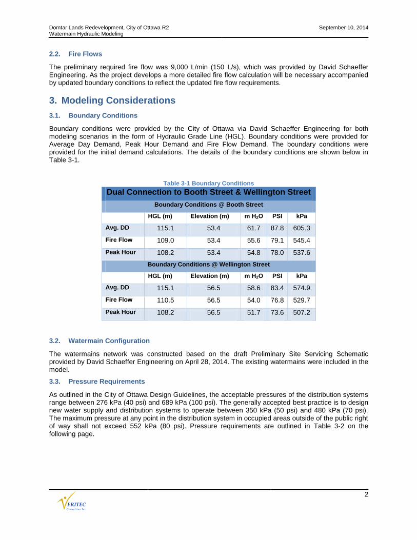
Boundary conditions were provided by the City of Ottawa via David Schaeffer Engineering for both modeling scenarios in the form of Hydraulic Grade Line (HGL). Boundary conditions were provided for Average Day Demand, Peak Hour Demand and Fire Flow Demand. The boundary conditions were provided for the initial demand calculations. The details of the boundary conditions are shown below in Table 3-1.
Table 3-1 Boundary Conditions
Dual Connection to Booth Street & Wellington Street
Boundary Conditions @ Booth Street
HGL (m) Elevation (m) m H2O PSI kPa
Avg. DD 115.1 53.4 61.7 87.8 605.3
Fire Flow 109.0 53.4 55.6 79.1 545.4
Peak Hour 108.2 53.4 54.8 78.0 537.6
Boundary Conditions @ Wellington Street
HGL (m) Elevation (m) m H2O PSI kPa
Avg. DD 115.1 56.5 58.6 83.4 574.9
Fire Flow 110.5 56.5 54.0 76.8 529.7
Peak Hour 108.2 56.5 51.7 73.6 507.2
3.2. Watermain Configuration
The watermains network was constructed based on the draft Preliminary Site Servicing Schematic provided by David Schaeffer Engineering on April 28, 2014. The existing watermains were included in the model.
3.3. Pressure Requirements
As outlined in the City of Ottawa Design Guidelines, the acceptable pressures of the distribution systems range between 276 kPa (40 psi) and 689 kPa (100 psi). The generally accepted best practice is to design new water supply and distribution systems to operate between 350 kPa (50 psi) and 480 kPa (70 psi). The maximum pressure at any point in the distribution system in occupied areas outside of the public right of way shall not exceed 552 kPa (80 psi). Pressure requirements are outlined in Table 3-2 on the following page.

Domtar Lands Redevelopment, City of Ottawa R2 Watermain Hydraulic Modeling
September 10, 2014
3
Table 3-2 Pressure Requirements
Demand Condition Minimum Pressure Maximum Pressure
(kPa) (psi) (kPa) (psi)
Normal Operating Pressure (maximum daily flow) 350 50 480 70
Maximum Hourly Demand (minimum allowable pressure) 276 40
Maximum Fixture Pressure (Ontario Building Code) 552 80
Maximum Distribution Pressure (minimum hour check) 552 80
Maximum Day Plus Fire 140 20
3.4. Elevations
Elevations and modelled junctions were assigned according to a Preliminary Site Servicing Schematic provided by David Schaeffer Engineering on April 28, 2014 and City of Ottawa 2013 Water Distribution Map. Modelled node elevations were assigned to nearest centre line of road elevations or spot elevations.
3.5. Pipe Characteristics
Pipe characteristics of internal diameter (ID) and Hazen-Williams C-Factors were assigned according to the City of Ottawa Design Guidelines for PVC watermain material outlined below in Table 3-3.
Table 3-3 Model Pipe Characteristics
Nominal Diameter (mm)
ID PVC (mm) C-Factor
150 155 100
200 204 110
Existing Infrastructure
The ID and C-Factor for the existing pipes was assigned based on City of Ottawa Design Guidelines though due the age and material it is likely that pipe characteristics do not conform to the guidelines. The existing infrastructure was installed between 1874 and 1984 and is of Ductile Iron (DI) or Unlined Cast Iron (ULI) materials. For the purpose of this analysis, the ID and C-Factor of all existing pipes was modelled according to MOE and City of Ottawa design guidelines assuming that infrastructure is maintain at generally acceptable conditions. The actual condition of these pipes may result in C-Factors much lower than those used in this analysis. C-Factor testing and/or internal inspection of the pipes is recommended to calibrate the hydraulic model and for condition assessment purposes.
4. Modelling Results
The proposed watermains were sized to the minimum diameter which would satisfy the greater of maximum day plus fire and maximum hour demand. Modelling was carried out for Average Day Demand, Peak Hour Demand and Maximum Day plus Fire Demand using an InfoWater model of the system. Hydraulic analysis was carried out for the two (2) connection scenarios.
4.1. System Pressures
The modelling indicates that the development can be adequately serviced by the proposed watermain configuration and both connection scenarios. The modelled service pressures for Average Day Demand and Peak Hour Demand are shown in Table 4-1 on the following page. Detailed pipe and junction tables are located in Appendix B.
Pressures during Average Day Demand range between 585 kPa and 650 kPa within the MOE and City of Ottawa guidelines but exceeding the OBC fixture pressure of 552 kPa. We do not recommend pressure reduction within the distribution system since all of the proposed buildings will be multi-floor residential and commercial buildings where pressures can be addressed internal by the mechanical systems designers.

Domtar Lands Redevelopment, City of Ottawa R2 Watermain Hydraulic Modeling
September 10, 2014
4
Table 4-1 Summary of Available Service Pressures
Summary of Service Pressures
Average Day Demand Pressure (kPa)
Peak Hour Demand Pressure (kPa)
Scenario 2 (2 Connections)
585 - 650 515 - 580
Note: Values rounded to nearest 5 kPa.
4.2. Available Fire Flows
The minimum allowable pressure under fire flow conditions is 138 kPa (20 psi) at the location of the fire. Fire flow modelling was carried out for both connection scenarios.
The modelling indicates that the fire flows requirements can be met with both connection scenarios. A summary of available fire flows for each scenario is shown below in Table 4-2. Detailed fire flow reports are available in Appendix C.
Table 4-2 Summary of Available Fire Flows
Scenario Required Fire Flow (L/s) Minimum Available Fire Flow (L/s)
Dual Connection 150 199
4.3. Transient Pressures
According to City of Ottawa Design Guidelines all watermains and thrust block shall be designed to withstand the maximum operating pressure plus the transient surge pressure created by stopping a water column moving at 0.6 m/s.
A PVC pipe with dimension ratio (DR) of 18 will experience a pressure surge of 240 kPa for an instantaneous stoppage of water traveling at 0.6 m/s. The maximum operating pressure (650 kPa) plus the transient pressure (240 kPa) will be about 890 kPa which is below the 1030 kPa (150 psi) pressure rating of the DR 18 PVC pipe. All pipes restraints and thrust blocks should be designed to a minimum 1030 kPa (150 psi) design pressure.
5. Conclusions & Recommendations
The proposed preliminary watermain servicing for the Domtar Lands Redevelopment can deliver all domestic and fire flows as per the Ministry of Environment and City of Ottawa Design Guidelines as follows:
Preliminary fire flows are achievable for both connection scenarios.
The service pressures are expected to range between 515 kPa and 650 kPa within the MOE and City of Ottawa guidelines but exceeding the OBC fixture pressure of 552 kPa at some times and locations. We do not recommend pressure reduction within the distribution system since all of the proposed buildings will be multi-floor residential and commercial buildings where pressures can be addressed internal by the mechanical systems designers.
In order to refine the hydraulic modelling the following recommendations are made:
1. Condition assessment of existing watermains that will be used to service future developments. 2. More detailed fire flow calculation once the proposed structures are more defined.

Appendix A
Demand Calculations & Boundary Conditions
1
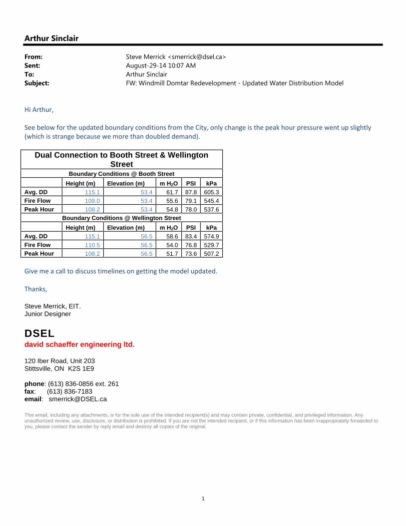
Arthur Sinclair
From: Steve Merrick <[email protected]>Sent: August-29-14 10:07 AMTo: Arthur SinclairSubject: FW: Windmill Domtar Redevelopment - Updated Water Distribution Model
Hi Arthur,
See below for the updated boundary conditions from the City, only change is the peak hour pressure went up slightly(which is strange because we more than doubled demand).
Dual Connection to Booth Street & WellingtonStreet
Boundary Conditions @ Booth StreetHeight (m) Elevation (m) m H2O PSI kPa
Avg. DD 115.1 53.4 61.7 87.8 605.3Fire Flow 109.0 53.4 55.6 79.1 545.4Peak Hour 108.2 53.4 54.8 78.0 537.6
Boundary Conditions @ Wellington StreetHeight (m) Elevation (m) m H2O PSI kPa
Avg. DD 115.1 56.5 58.6 83.4 574.9Fire Flow 110.5 56.5 54.0 76.8 529.7Peak Hour 108.2 56.5 51.7 73.6 507.2
Give me a call to discuss timelines on getting the model updated.
Thanks,
Steve Merrick, EIT.Junior Designer
DSELdavid schaeffer engineering ltd.
120 Iber Road, Unit 203Stittsville, ON K2S 1E9
phone: (613) 836-0856 ext. 261fax: (613) 836-7183email: [email protected]
This email, including any attachments, is for the sole use of the intended recipient(s) and may contain private, confidential, and privileged information. Anyunauthorized review, use, disclosure, or distribution is prohibited. If you are not the intended recipient, or if this information has been inappropriately forwarded toyou, please contact the sender by reply email and destroy all copies of the original.

2
From: Steve Merrick [mailto:[email protected]]Sent: August-28-14 2:52 PMTo: Arthur SinclairSubject:Windmill Domtar Redevelopment - Updated Water Distribution Model
Hi Arthur,
After getting comments back from the City and coordinating with the NCC on their preferable watermain connection wehave some updates required for the water distribution model. Firstly, the NCC have indicated that their preferableoption for a 2nd watermain connection will be the 400mm watermain within Wellington Street, with a connection overthe portage bridge to our site. This was already one of your scenarios from our last submission so there should be noupdate to the pipe layouts. The city has requested that we use 350 L/p/d instead of our original 163 L/p/d used in ourlast submission, I have summarized the revised water demands below:
L/min L/sAvg. Daily 579.2 9.65Max Day 1266.5 21.11
Peak Hour 1924.4 32.07
We will need the model to be updated to include the new demands. If possible we would like to know what sort ofimpacts there could potential be, specifically to the chlorine residual, sizing a system for 350 L/p/day when in actual factthe demand will be sustainably lower.
We are waiting on updated boundary conditions based on this new flow rate from the City and should have them bytomorrow. I thought I should provide you with our plan for the updated water distribution model to give you time torespond with an approximate timeline. I will follow up on this email tomorrow with updated boundary conditions,please let me know if you have any questions or concerns.
Thanks,
Steve Merrick, EIT.Junior Designer
DSELdavid schaeffer engineering ltd.
120 Iber Road, Unit 203Stittsville, ON K2S 1E9
phone: (613) 836-0856 ext. 261fax: (613) 836-7183email: [email protected]
This email, including any attachments, is for the sole use of the intended recipient(s) and may contain private, confidential, and privileged information. Anyunauthorized review, use, disclosure, or distribution is prohibited. If you are not the intended recipient, or if this information has been inappropriately forwarded toyou, please contact the sender by reply email and destroy all copies of the original.

1
Andrew Komarnycky
From: Steve Merrick <[email protected]>Sent: April-28-14 1:01 PMTo: Arthur SinclairCc: [email protected]: RE: Domtar Lands Redevelopment - Ontario/Quebec Water Distribution ModelAttachments: W_366-031.pdf; W_366-030.pdf; cons_2014-04-17_717_adf-Ontario_coord.dwg
Hi Arthur,
To follow up on our phone conversation please find the following information attached:
- Water Infrastructure Maps of the site + further south- CAD of the watermain layout and site plan- Find below the water demands for the proposed site
L/min L/sAvg. Daily 295.8 4.93Max Day 629.0 10.48
Peak Hour 966.6 16.11Fire Flow 9,000 L/min + Max Day
- Find below the boundary conditions for the single and dual connection scenarios (I will get all relevantcorrespondence with the city together and sent over later)
Single Connection to Booth StreetBoundary Conditions @ Booth Street
Height (m) Elevation (m) m H2O PSI kPaAvg. DD 115.1 53.4 61.7 87.8 605.3Fire Flow 108.7 53.4 55.3 78.7 542.5Peak Hour 107.8 53.4 54.4 77.4 533.7
Dual Connection to Booth Street & WellingtonStreet
Boundary Conditions @ Booth StreetHeight (m) Elevation (m) m H2O PSI kPa
Avg. DD 115.1 53.4 61.7 87.8 605.3Fire Flow 109.0 53.4 55.6 79.1 545.4Peak Hour 107.8 53.4 54.4 77.4 533.7
Boundary Conditions @ Wellington StreetHeight (m) Elevation (m) m H2O PSI kPa
Avg. DD 115.1 56.5 58.6 83.4 574.9Fire Flow 110.5 56.5 54.0 76.8 529.7Peak Hour 107.8 56.5 51.3 73.0 503.3
The electronic files are accompanied by the following disclaimers: The requested electronic file(s) (the “Files”) remain the property of DSEL. No warranties or guarantees are made that the Files represent or reflect the complete scope of work and/or as-
built condition.
arthur
Typewritten text
SUPERSEDED

DSEL assumes no responsibility for data files supplied in electronic format. Such data is being provided as acourtesy only.
The Company receiving the Files and users thereof accept full responsibility for verifying the accuracy andcompleteness of the Files and shall indemnify and hold DSEL harmless from any claims or damages arising fromthe use of the Files.
In the event that drawing Files transferred electronically contain electronic copies of permits or professionalseals, the Files shall be immediately returned to DSEL and all copies thereof destroyed.
No use shall be made of the Files for any purpose other than that for which they were originally intended withoutthe express written consent of DSEL.
No retransmission of the Files in any form to any third party is permitted unless authorized in writing by DSEL
Steve Merrick, EIT.Junior Designer
DSELdavid schaeffer engineering ltd.
120 Iber Road, Unit 203Stittsville, ON K2S 1E9
phone: (613) 836-0856 ext. 261fax: (613) 836-7183email: [email protected]
This email, including any attachments, is for the sole use of the intended recipient(s) and may contain private, confidential, and privileged information. Anyunauthorized review, use, disclosure, or distribution is prohibited. If you are not the intended recipient, or if this information has been inappropriately forwarded toyou, please contact the sender by reply email and destroy all copies of the original.

14-717
Les Iles / The Isles
Proposed Conditions for The Isles
(Ottawa, Ontario)
2014-04-15
Water Demand Design Flows per Unit Count
City of Ottawa - Water Distribution Guidelines, July 2010
Domestic Demand
Type of Housing Per / Unit Units Pop
Single Family 3.4 0
Semi-detached 2.7 0
Townhouse 2.7 0
Apartment 0
Bachelor 1.4 0
1 Bedroom 1.4 0
2 Bedroom 2.1 0
3 Bedroom 3.1 0
Average 1.8 1212 2182
Pop
m3/d L/min m
3/d L/min m
3/d L/min
Total Domestic Demand 2182 355.7 247.0 800.2 555.7 1202.2 834.8
Institutional / Commercial / Industrial Demand
Property Type Units m3/d L/min m
3/d L/min m
3/d L/min
Commercial floor space 2.5 L/m2/d 32,955 82.39 57.2 123.6 85.8 222.4 154.5
Office 75 L/9.3m2/d 0.00 0.0 0.0 0.0 0.0 0.0
Industrial - Light 35,000 L/gross ha/d 0.00 0.0 0.0 0.0 0.0 0.0
Industrial - Heavy 55,000 L/gross ha/d 0.00 0.0 0.0 0.0 0.0 0.0
Total I/CI Demand 82.4 57.2 123.6 85.8 222.4 154.5
Total Demand 438.1 304.2 923.8 641.5 1424.6 989.3
Unit Rate
Note: Residential average daily water demand calcualted using City of Ottawa`s Draft Infrastructure Master Plan, dated Septmeber 2013 demand
of 163 L/person/day
Avg. Daily Max Day Peak Hour
Avg. Daily Max Day Peak Hour
Z:\Projects\14-717_windmill-the_isles\B_Design\B1_Analysis\B1-5_Water\wtr-2014-04-09_717_slm.xlsx
arthur
Typewritten text
SUPERSEDED

Appendix B
Modeling SchematicsPipe and Junction Tables

>
>
BOOTH ST
MIDDLE
ST
WELLINGTON ST
TURN LA
NE
TIMBERSLIDE ST LETT
ST
WEL
LIN
GTO
N S
T
WELLINGTON ST P29
P33
P37
P25
P7
P9
P35
P41
P11
P53
P17
P21
P15
P47
P3
P19
P39
P13
P23
P5
P45
RES
3
RES
1J5
J9
J29
J27
J23
J41
J37
J35
J31
J19
J17
J15
J11
Lege
ndPi
peR
UN
_DIA
M15
5
204
297
Exis
ting
Bui
ldin
gs
Dom
tar L
ands
Red
evel
opm
ent -
Pro
pose
d W
ater
Dis
tribu
tion
Sys
tem
Lay
out
±
030
6090
120 M
eter
s
Verit
ec C
onsu
lting
Inc.
1495
Bon
hill
Rd.
Uni
t #12
Mis
siss
auga
, ON
, L5T
1M
2Te
l.: (9
05) 6
96-9
391

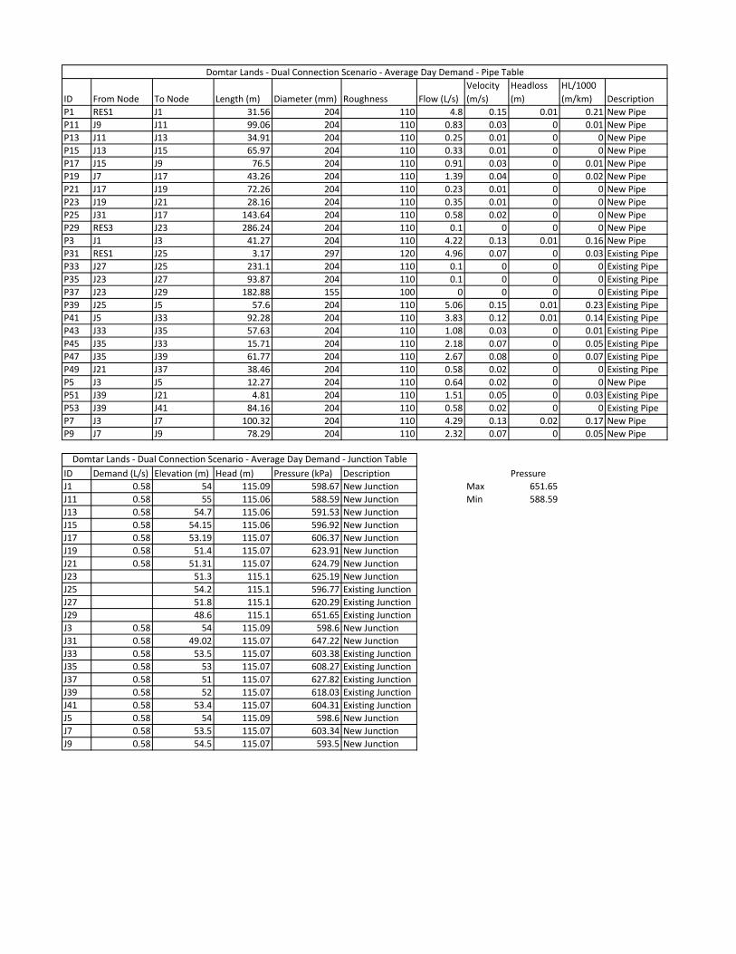
ID From Node To Node Length (m) Diameter (mm) Roughness Flow (L/s)
Velocity
(m/s)
Headloss
(m)
HL/1000
(m/km) Description
P1 RES1 J1 31.56 204 110 15.65 0.48 0.06 1.85 New Pipe
P11 J9 J11 99.06 204 110 2.7 0.08 0.01 0.07 New Pipe
P13 J11 J13 34.91 204 110 0.81 0.02 0 0.01 New Pipe
P15 J13 J15 65.97 204 110 1.08 0.03 0 0.01 New Pipe
P17 J15 J9 76.5 204 110 2.97 0.09 0.01 0.08 New Pipe
P19 J7 J17 43.26 204 110 4.52 0.14 0.01 0.18 New Pipe
P21 J17 J19 72.26 204 110 0.74 0.02 0 0.01 New Pipe
P23 J19 J21 28.16 204 110 1.15 0.04 0 0.01 New Pipe
P25 J31 J17 143.64 204 110 1.89 0.06 0.01 0.04 New Pipe
P29 RES3 J23 286.24 204 110 0.32 0.01 0 0 New Pipe
P3 J1 J3 41.27 204 110 13.76 0.42 0.06 1.46 New Pipe
P31 RES1 J25 3.17 297 120 16.15 0.23 0 0.27 Existing Pipe
P33 J27 J25 231.1 204 110 0.32 0.01 0 0 Existing Pipe
P35 J23 J27 93.87 204 110 0.32 0.01 0 0 Existing Pipe
P37 J23 J29 182.88 155 100 0 0 0 0 Existing Pipe
P39 J25 J5 57.6 204 110 16.48 0.5 0.12 2.03 Existing Pipe
P41 J5 J33 92.28 204 110 12.49 0.38 0.11 1.22 Existing Pipe
P43 J33 J35 57.63 204 110 3.51 0.11 0.01 0.12 Existing Pipe
P45 J35 J33 15.71 204 110 7.09 0.22 0.01 0.43 Existing Pipe
P47 J35 J39 61.77 204 110 8.71 0.27 0.04 0.62 Existing Pipe
P49 J21 J37 38.46 204 110 1.89 0.06 0 0.04 Existing Pipe
P5 J3 J5 12.27 204 110 2.09 0.06 0 0.04 New Pipe
P51 J39 J21 4.81 204 110 4.93 0.15 0 0.22 Existing Pipe
P53 J39 J41 84.16 204 110 1.89 0.06 0 0.04 Existing Pipe
P7 J3 J7 100.32 204 110 13.97 0.43 0.15 1.5 New Pipe
P9 J7 J9 78.29 204 110 7.56 0.23 0.04 0.48 New Pipe
ID Demand (L/s) Elevation (m) Head (m) Pressure (kPa) Description
J1 1.89 54 108.14 530.55 New Junction Pressure
J11 1.89 55 107.89 518.25 New Junction Max 584.03
J13 1.89 54.7 107.89 521.19 New Junction Min 518.25
J15 1.89 54.15 107.89 526.59 New Junction
J17 1.89 53.19 107.92 536.35 New Junction
J19 1.89 51.4 107.92 553.88 New Junction
J21 1.89 51.31 107.92 554.77 New Junction
J23 0 51.3 108.2 557.57 New Junction
J25 0 54.2 108.2 529.15 Existing Junction
J27 0 51.8 108.2 552.67 Existing Junction
J29 0 48.6 108.2 584.03 Existing Junction
J3 1.89 54 108.08 529.96 New Junction
J31 1.89 49.02 107.92 577.16 New Junction
J33 1.89 53.5 107.97 533.76 Existing Junction
J35 1.89 53 107.96 538.6 Existing Junction
J37 1.89 51 107.92 557.79 Existing Junction
J39 1.89 52 107.92 548.02 Existing Junction
J41 1.89 53.4 107.92 534.27 Existing Junction
J5 1.89 54 108.08 529.96 New Junction
J7 1.89 53.5 107.93 533.39 New Junction
J9 1.89 54.5 107.89 523.22 New Junction
Domtar Lands - Dual Connection Scenario - Peak Hour Demand - Pipe Table
Domtar Lands - Dual Connection Scenario - Peak Hour - Junction Table
ID From Node To Node Length (m) Diameter (mm) Roughness Flow (L/s)
Velocity
(m/s)
Headloss
(m)
HL/1000
(m/km) Description
P1 RES1 J1 31.56 204 110 4.8 0.15 0.01 0.21 New Pipe
P11 J9 J11 99.06 204 110 0.83 0.03 0 0.01 New Pipe
P13 J11 J13 34.91 204 110 0.25 0.01 0 0 New Pipe
P15 J13 J15 65.97 204 110 0.33 0.01 0 0 New Pipe
P17 J15 J9 76.5 204 110 0.91 0.03 0 0.01 New Pipe
P19 J7 J17 43.26 204 110 1.39 0.04 0 0.02 New Pipe
P21 J17 J19 72.26 204 110 0.23 0.01 0 0 New Pipe
P23 J19 J21 28.16 204 110 0.35 0.01 0 0 New Pipe
P25 J31 J17 143.64 204 110 0.58 0.02 0 0 New Pipe
P29 RES3 J23 286.24 204 110 0.1 0 0 0 New Pipe
P3 J1 J3 41.27 204 110 4.22 0.13 0.01 0.16 New Pipe
P31 RES1 J25 3.17 297 120 4.96 0.07 0 0.03 Existing Pipe
P33 J27 J25 231.1 204 110 0.1 0 0 0 Existing Pipe
P35 J23 J27 93.87 204 110 0.1 0 0 0 Existing Pipe
P37 J23 J29 182.88 155 100 0 0 0 0 Existing Pipe
P39 J25 J5 57.6 204 110 5.06 0.15 0.01 0.23 Existing Pipe
P41 J5 J33 92.28 204 110 3.83 0.12 0.01 0.14 Existing Pipe
P43 J33 J35 57.63 204 110 1.08 0.03 0 0.01 Existing Pipe
P45 J35 J33 15.71 204 110 2.18 0.07 0 0.05 Existing Pipe
P47 J35 J39 61.77 204 110 2.67 0.08 0 0.07 Existing Pipe
P49 J21 J37 38.46 204 110 0.58 0.02 0 0 Existing Pipe
P5 J3 J5 12.27 204 110 0.64 0.02 0 0 New Pipe
P51 J39 J21 4.81 204 110 1.51 0.05 0 0.03 Existing Pipe
P53 J39 J41 84.16 204 110 0.58 0.02 0 0 Existing Pipe
P7 J3 J7 100.32 204 110 4.29 0.13 0.02 0.17 New Pipe
P9 J7 J9 78.29 204 110 2.32 0.07 0 0.05 New Pipe
ID Demand (L/s) Elevation (m) Head (m) Pressure (kPa) Description Pressure
J1 0.58 54 115.09 598.67 New Junction Max 651.65
J11 0.58 55 115.06 588.59 New Junction Min 588.59
J13 0.58 54.7 115.06 591.53 New Junction
J15 0.58 54.15 115.06 596.92 New Junction
J17 0.58 53.19 115.07 606.37 New Junction
J19 0.58 51.4 115.07 623.91 New Junction
J21 0.58 51.31 115.07 624.79 New Junction
J23 51.3 115.1 625.19 New Junction
J25 54.2 115.1 596.77 Existing Junction
J27 51.8 115.1 620.29 Existing Junction
J29 48.6 115.1 651.65 Existing Junction
J3 0.58 54 115.09 598.6 New Junction
J31 0.58 49.02 115.07 647.22 New Junction
J33 0.58 53.5 115.07 603.38 Existing Junction
J35 0.58 53 115.07 608.27 Existing Junction
J37 0.58 51 115.07 627.82 Existing Junction
J39 0.58 52 115.07 618.03 Existing Junction
J41 0.58 53.4 115.07 604.31 Existing Junction
J5 0.58 54 115.09 598.6 New Junction
J7 0.58 53.5 115.07 603.34 New Junction
J9 0.58 54.5 115.07 593.5 New Junction
Domtar Lands - Dual Connection Scenario - Average Day Demand - Junction Table
Domtar Lands - Dual Connection Scenario - Average Day Demand - Pipe Table

Appendix C
Fire Flow Report

>
>
MID
DLE S
T
BOOTH ST
WELLINGTON ST
TURN LA
NE
TIMBERSLIDE STWELLINGTON ST
WELL
INGTO
N ST
222
L/s
339
L/s
274
L/s
364
L/s
368
L/s
199
L/s
337
L/s
207
L/s
202
L/s
202
L/s
230
L/s
681
L/s 80
1 L/
s
Lege
ndPi
peR
UN
_DIA
M15
5
204
297
Exis
ting
Bui
ldin
gs
Dom
tar L
ands
Red
evel
opm
ent -
Fire
Flo
w (1
50 L
/s)
±
025
5075
100 M
eter
s
Verit
ec C
onsu
lting
Inc.
1495
Bon
hill
Rd.
Uni
t #12
Mis
siss
auga
, ON
, L5T
1M
2Te
l.: (9
05) 6
96-9
391

ID
Static Demand
(L/s)
Static Pressure
(kPa)
Static
Head (m)
Fire-Flow
Demand (L/s)
Residual
Pressure (kPa)
Available Flow
at Hydrant (L/s)
Available Flow
Pressure (kPa)
J1 1.23 538.7 108.97 150 518.5 801.35 139.96
J11 1.23 527.78 108.86 150 297.09 202.15 139.96
J13 1.23 530.71 108.86 150 297.08 201.56 139.96
J15 1.23 536.11 108.86 150 309.98 206.87 139.96
J17 1.23 545.67 108.88 150 447.69 338.55 139.96
J19 1.23 563.21 108.88 150 460.38 336.97 139.96
J21 1.23 564.1 108.88 150 463.04 340.88 139.96
J3 1.23 538.44 108.95 150 510.11 680.92 139.96
J31 1.23 586.51 108.87 150 315.04 199.01 139.96
J33 1.23 542.84 108.9 150 459.14 367.54 139.96
J35 1.23 547.71 108.89 150 461.45 363.85 139.96
J37 1.23 567.13 108.87 150 419.62 274.12 139.96
J39 1.23 557.34 108.88 150 456.87 338.93 139.96
J41 1.23 543.61 108.87 150 341.5 222.03 139.96
J7 1.23 542.67 108.88 150 454.84 359.28 139.96
J9 1.23 532.71 108.86 150 346.15 229.62 139.96
Domtar Lands - Dual Connection Scenario - Fire Flow (150 L/s)