Waterfield Street Drainage Study
90
Waterfield Street Drainage Study FINAL REPORT Final 18 July 2008
Transcript of Waterfield Street Drainage Study

Waterfield Street Drainage Study
FINAL REPORT
Final
18 July 2008
The SKM logo is a trade mark of Sinclair Knight Merz Pty Ltd. © Sinclair Knight Merz Pty Ltd, 2006
Waterfield Street Drainage Study
FINAL REPORT
Final
18 July 2008
Sinclair Knight Merz ABN 37 001 024 095 590 Orrong Road, Armadale 3143 PO Box 2500 Malvern VIC 3144 Australia Tel: +61 3 9248 3100 Fax: +61 3 9248 3400 Web: www.skmconsulting.com
COPYRIGHT: The concepts and information contained in this document are the property of Sinclair Knight Merz Pty Ltd. Use or copying of this document in whole or in part without the written permission of Sinclair Knight Merz constitutes an infringement of copyright.
LIMITATION: This report has been prepared on behalf of and for the exclusive use of Sinclair Knight Merz Pty Ltd’s Client, and is subject to and issued in connection with the provisions of the agreement between Sinclair Knight Merz and its Client. Sinclair Knight Merz accepts no liability or responsibility whatsoever for or in respect of any use of or reliance upon this report by any third party.

Final Report
SINCLAIR KNIGHT MERZ
I:\VWES\Projects\VW03961\Deliverables\R03_mj_WaterfieldSt_final.docx PAGE i
Contents
1. Introduction 5
1.1. Background 5
1.2. Project Aims 5
1.3. Tasks involved in study 6
2. Study Area 7
2.1. The Harding Street catchment 7
2.2. The study area 8
3. Survey 10
3.1. MOCS Search 10
3.2. Existing data 10
3.3. Site survey 11
4. Hydrology 13
4.1. Introduction 13
4.2. Modelling Approaches 13
4.3. Adopted Parameters 13
5. Hydraulic analysis of upstream tributary system 15
5.1. Details of existing system 15
5.2. Method of analysis 17
5.2.1. Rational Method 17
5.2.2. Hydraulic Grade Line (HGL) 18
5.2.3. Inlet Pit Capacities 18
5.3. Results 19
5.4. Suggested system augmentation works 21
6. Hydraulic analysis of Coburg Shopping Centre Drainage System 22
6.1. Introduction 22
6.2. Details of existing system 22
6.3. Model Setup 25
6.4. Results 26
7. Existing drainage issues around Coburg shopping centre 27
8. Potential augmentation options 29
8.1. Option 1 – Pipe Augmentation along Munro Street 32
8.1.1. Option 1 Hydraulic Results 33
8.1.2. Option 1 Costs 33
8.1.3. Option 1 Feasibility 34

Final Report
SINCLAIR KNIGHT MERZ
I:\VWES\Projects\VW03961\Deliverables\R03_mj_WaterfieldSt_final.docx PAGE ii
8.2. Option 2 – Relandscaping Defacto Retarding Basin 36
8.2.1. Option 2 Hydraulic Results 37
8.2.2. Option 2 Feasibility 37
8.3. Option 3 – Controlled Flows East and West of Bell Street Railway Crossing 38
8.3.1. Option 3 hydraulic results 39
8.4. Option 4 – Storages underneath the Car Park 40
8.4.1. Option 4 – Hydraulic Results 42
8.4.2. Option 4 Costs 43
8.4.3. Feasibility of Option 4 44
8.5. Option 5 – Pipe Augmentation through Car Park 45
8.5.1. Option 5 – Hydraulic Results 46
8.5.2. Option 5 – Costs 47
8.5.3. Option 5 - Feasibility 47
8.6. Option 6 – Reprofiling Waterfield Street 48
8.6.1. Option 6 – Hydraulic Results 49
8.7. Option 7 – Pipe Augmentation along Waterfield Street 50
8.7.1. Option 7 – Hydraulic Results 51
8.7.2. Option 7 – Costs 51
8.7.3. Option 7 – Feasibility 52
8.8. Combined Option 1 53
8.8.1. Combined Option 1 – Hydraulic Results 53
8.8.2. Combined Option 1 – Costs 54
8.8.3. Combined Option 1 – Feasibility 54
8.9. Combined Option 2 56
8.9.1. Hydraulic Results 56
8.9.2. Combined Option 2 – Costs 56
8.9.3. Combined Option 2 – Feasibility 57
9. Developer Contribution Strategies for Drainage and Flood Mitigation Works 59
9.1. Types of strategies 59
9.2. Method of implementing drainage contribution charges 60
9.3. Discussion 62
10. Recommendations 63
10.1. Recommended Option A 63
10.2. Recommended Option B 63
10.3. Comparison of Hydraulic Results for Recommended Options 64
10.4. Other Issues to be Considered 64
10.5. Consideration of litter and blockages 65
10.6. Developer contributions 65

Final Report
SINCLAIR KNIGHT MERZ
I:\VWES\Projects\VW03961\Deliverables\R03_mj_WaterfieldSt_final.docx PAGE iii
11. References 67
Appendix A Survey Results 68
Appendix B RORB Modelling 72
B.1 RORB Overview 72
B.2 Design Rainfall Intensities 72
B.3 Storages 73
B.4 New Sub-Areas 74
Appendix C Hydraulic Grade Line Analysis 76
Appendix D XP Storm Inputs 83
D.1 Hydrographs from RORB 83
Appendix E Flood extents and depth plans 88

Final Report
SINCLAIR KNIGHT MERZ
I:\VWES\Projects\VW03961\Deliverables\R03_mj_WaterfieldSt_final.docx PAGE iv
Document history and status
Revision Date issued Reviewed by Approved by Date approved Revision type
Draft 15 Jan 2008 D Sheehan R Morden 15 Jan 2008 Draft issue to client
Final 18 July 2008 D Sheehan R Morden 18 July 2008 Final issue to client
Distribution of copies
Revision Copy no Quantity Issued to
1 pdf Grant Thorne (Moreland City Council)
Printed: 18 July 2008
Last saved: 18 July 2008 11:59 AM
File name: I:\VWES\Projects\VW03961\Deliverables\R03_mj_WaterfieldSt_final.docx
Author: Robert Morden, Madeleine Jenkins
Project manager: Robert Morden
Name of organisation: City of Moreland
Name of project: Waterfield Street Drainage Study
Name of document: Final Report
Document version: Final
Project number: VW03961

Waterfield St Drainage Study
SINCLAIR KNIGHT MERZ The SKM logo is a trade mark of Sinclair Knight Merz Pty Ltd. © Sinclair Knight Merz Pty Ltd, 2006
I:\VWES\Projects\VW03961\Deliverables\R03_mj_WaterfieldSt_final.docx PAGE 5
1. Introduction
1.1. Background
Moreland City Council has commissioned Sinclair Knight Merz (SKM) to assess the existing
drainage system around the Coburg shopping centre, specifically the area bounded by Munro
St, Sutherland St, Sydney Rd, and O’Hea St.
This study has been prompted by two key issues. Firstly, the Coburg Library on the corner of
Waterfield and Victoria Sts has been flooded on more than one occasion as a result of surface
flows in Victoria St flowing through the front door of the building. Council would like to
better understand the level of flooding risk for this valuable asset. Secondly, a large part of the
Coburg shopping centre has been purchased by council, predominantly between Waterfield
Street and Coburg Railway Station, with the intention of allowing major redevelopment of the
area. Flooding of the Coburg library has indicated that there are flooding problems in this
area, so council would like to better understand the flooding characteristics of the Coburg
shopping centre so that any future redevelopment is better informed about the likely flows that
will need to be catered for. In addition, Council would like to know if there are any flooding
issues in the Coburg shopping centre which can be fixed relatively simply.
This drainage study focuses on the redevelopment areas between Waterfield St and Coburg
Railway Station, and also on the Coburg Library site which has recently been subject to
flooding. Options for improving the drainage in these particular locations are provided, along
with some guidance of costs involved in any drainage works, and some broad indications of
how these costs could be passed on to the Waterfield St redevelopment.
This project follows on from an initial proposal, which was submitted to Moreland City
Council in August 2006, for a drainage analysis in the vicinity of Coburg Library. However,
since then that proposal has been expanded to include the proposed redevelopment in
Waterfield St, and other drainage issues identified upstream of the Harding Street main drain.
1.2. Project Aims
The objectives of this drainage study are to:
Investigate the capacity of the existing system of pits and pipes upstream of the shopping
centre.
To identify key flow paths and areas of inundation within the detailed study area (Coburg
Shopping Centre) including flood levels adjacent to key buildings including the Coburg
Library.

Waterfield St Drainage Study
SINCLAIR KNIGHT MERZ The SKM logo is a trade mark of Sinclair Knight Merz Pty Ltd. © Sinclair Knight Merz Pty Ltd, 2006
I:\VWES\Projects\VW03961\Deliverables\R03_mj_WaterfieldSt_final.docx PAGE 6
To identify opportunities to upgrade the drainage system to improve existing levels of
flood protection within the Coburg Shopping Centre.
1.3. Tasks involved in study
The Coburg drainage study includes the following tasks:
Review of existing underground services located using a MOCS search of the Coburg
shopping centre.
Detailed site survey of existing overland flow paths and street geometries throughout the
Coburg shopping centre. This task also includes surveying of several key pipe invert
locations.
Hydrological analysis using RORB in order to estimate inflows for the Coburg shopping
centre.
Hydraulic analysis for upstream tributaries including rational method calculations,
hydraulic grade line analysis, and assessment of inlet pit capacities.
Detailed hydraulic analysis of Coburg shopping centre using XP Storm
Identification, costing and assessment of upgrade opportunities within the Coburg
shopping centre.
Discussion of possible development contributions schemes to allow the costs of some
drainage works to be passed on to developers involved in the redevelopment of the
Coburg Shopping Centre.
Waterfield St Drainage Study
SINCLAIR KNIGHT MERZ The SKM logo is a trade mark of Sinclair Knight Merz Pty Ltd. © Sinclair Knight Merz Pty Ltd, 2006
I:\VWES\Projects\VW03961\Deliverables\R03_mj_WaterfieldSt_final.docx PAGE 7
2. Study Area
2.1. The Harding Street catchment
The study area is part of the Harding Street catchment, a small tributary of Merri Creek
approximately 7.5 km north of Melbourne CBD.
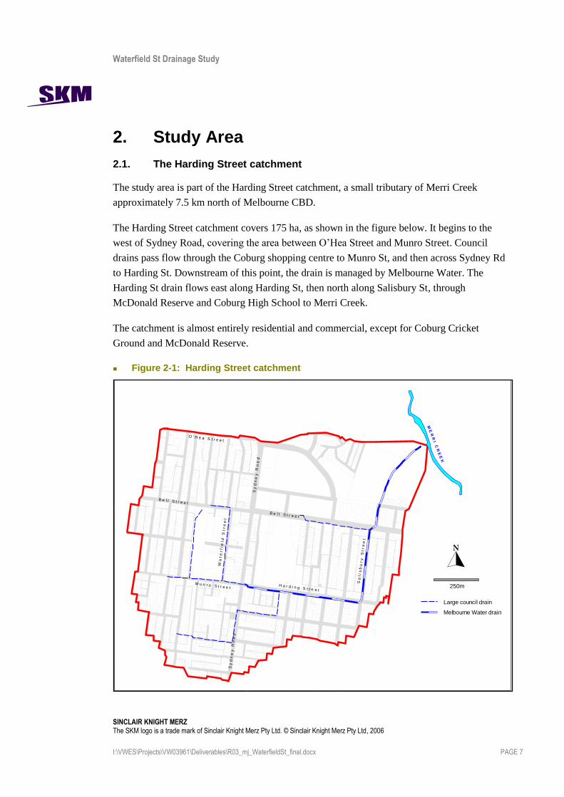
The Harding Street catchment covers 175 ha, as shown in the figure below. It begins to the
west of Sydney Road, covering the area between O’Hea Street and Munro Street. Council
drains pass flow through the Coburg shopping centre to Munro St, and then across Sydney Rd
to Harding St. Downstream of this point, the drain is managed by Melbourne Water. The
Harding St drain flows east along Harding St, then north along Salisbury St, through
McDonald Reserve and Coburg High School to Merri Creek.
The catchment is almost entirely residential and commercial, except for Coburg Cricket
Ground and McDonald Reserve.
Figure 2-1: Harding Street catchment
Melbourne Water drain
250m
Large council drain
M E
R R
I C R
E E
K
S a
l i s
b u
r y
S
t r
e e
t
H a r d i n g S t r e e t
B e l l S t r e e t
S y
d n
e y
R
o a
d
M u n r o S t r e e t
W a
t e
r f i
e l d
S
t r
e e
t
O ' H e a S t r e e t
S y
d n
e y
R
o a
d
B e l l S t r e e t

Waterfield St Drainage Study
SINCLAIR KNIGHT MERZ The SKM logo is a trade mark of Sinclair Knight Merz Pty Ltd. © Sinclair Knight Merz Pty Ltd, 2006
I:\VWES\Projects\VW03961\Deliverables\R03_mj_WaterfieldSt_final.docx PAGE 8
2.2. The study area
The study area is shown below. It includes the area upstream of the Harding St Main Drain
(Melbourne Water asset), bounded by Sydney Road, Munro Street, Sutherland St, Kendall St,
and O’Hea St.
In addition, more detailed hydraulic analyses have been undertaken for the main commercial
area, roughly bounded by Sydney Road, Munro St, the railway, and Bell St.

Waterfield St Drainage Study
SINCLAIR KNIGHT MERZ The SKM logo is a trade mark of Sinclair Knight Merz Pty Ltd. © Sinclair Knight Merz Pty Ltd, 2006
I:\VWES\Projects\VW03961\Deliverables\R03_mj_WaterfieldSt_final.docx PAGE 9
Figure 2-2: Study Area
100m
Large council drain
Melbourne Water drain
S y
d n
e y
R
o a
d
M u n r o S t r e e t
Coburg
Library
B e l l S t r e e t
O ' H e a S t r e e t
Coburg
Railw ay
Station
Study Area
Detailed
Study
Area
H u
d s
o n
S
t r
e e
t
W a
t e
r f i
e l d
S
t r
e e
tV i c t o r i a S t r e e t

Waterfield St Drainage Study
SINCLAIR KNIGHT MERZ The SKM logo is a trade mark of Sinclair Knight Merz Pty Ltd. © Sinclair Knight Merz Pty Ltd, 2006
I:\VWES\Projects\VW03961\Deliverables\R03_mj_WaterfieldSt_final.docx PAGE 10
3. Survey
3.1. MOCS Search
A MOCS search was undertaken within the detailed study area to identify the location of
existing infrastructure that may affect the feasibility of proposed drainage upgrade options.
Table 3-1 describes the services in the study area. Overall, proposed drainage upgrade options
will need to take these services into consideration.
Table 3-1: Description of Services within Coburg Shopping Centre
Asset Owner Description of Assets
Visionstream, Ncc – Vic Low risk of the works affecting the Nextgen Network – optical fibre cable. Cable runs east of Sydney road along Russell Street and is not in study area.
Yarra Trams and Swanston Trams Trams along Sydney Road
Alinta AE Minor Electricity Cables throughout study area
Telstra (Coburg) Minor telecommunication cables throughout study area and some major optic fibres along main roads including: Bell Street, Victoria Street, Munro Street and Sydney Road.
Tenix Maintenance Services (gas) High Pressure gas mains (140kPa – 515kPa) throughout the study area
Yarra Valley Water (Ltd.) Water mains and waste water mains throughout the study area
Melbourne Water Drainage pipeline along Harding Street but not in study area
Moreland City Council Drainage pipelines throughout the area
3.2. Existing data
Spatial data was provided by Melbourne Water including 1m contours over the study area and
the location of Harding Street drainage pipeline. There were also some 0.1 m natural surface
contours provided by Melbourne Water from Flood Plain Mapping, however this only covered
a small section near the Sydney Road and Harding Street intersection. Moreland City Council
provided the location of the inlet pits and council drains including some diameters of pipes but
no invert levels. A site inspection showed that some of the locations of the inlet pits were
inaccurate and raised questions about the location of some of the pipes.
Overall, the extent of the data was insufficient for a detailed hydraulic analysis and hence a
detailed site survey capturing key invert levels and key surface features was required.

Waterfield St Drainage Study
SINCLAIR KNIGHT MERZ The SKM logo is a trade mark of Sinclair Knight Merz Pty Ltd. © Sinclair Knight Merz Pty Ltd, 2006
I:\VWES\Projects\VW03961\Deliverables\R03_mj_WaterfieldSt_final.docx PAGE 11
3.3. Site survey
A detailed site survey was undertaken to better understand the likely direction of surface flow
within the detailed study area around the Coburg shopping centre. This task included the
detailed site survey of the following:
Pipe invert levels at selected locations;
Some cross sections of streets at key locations including edge of buildings, top of gutter,
gutter invert and several points across the road; and
Feature survey of public access areas (car parks, roads and reserves) around central
Coburg. Particular attention was given to drainage paths, change of grade and change of
surface (grass/asphalt).
Figure 3-1 shows a map of the surveyed area, cross sections and locations of surveyed pipe
inverts. Not all pipe inverts were required due to the nature of the analysis, but some
indicative levels along larger pipes were necessary. Note that Moreland City Council also
lifted pit lids at the downstream end of Munro Street.
The results of the feature survey and pipe inverts are shown in Appendix A.

Waterfield St Drainage Study
SINCLAIR KNIGHT MERZ The SKM logo is a trade mark of Sinclair Knight Merz Pty Ltd. © Sinclair Knight Merz Pty Ltd, 2006
I:\VWES\Projects\VW03961\Deliverables\R03_mj_WaterfieldSt_final.docx PAGE 12
Figure 3-1: Map of Surveyed Area

Waterfield St Drainage Study
SINCLAIR KNIGHT MERZ The SKM logo is a trade mark of Sinclair Knight Merz Pty Ltd. © Sinclair Knight Merz Pty Ltd, 2006
I:\VWES\Projects\VW03961\Deliverables\R03_mj_WaterfieldSt_final.docx PAGE 13
4. Hydrology
4.1. Introduction
The peak 1 year, 5 year, 20 year and 100 year Average Recurrence Interval (ARI) flows for
existing conditions were calculated using the hydrological model RORB (Monash University,
2007). A brief discussion of RORB is provided in Appendix B.
An existing RORB model for the entire Harding Street catchment was developed for
Melbourne Water in 2006. Based on this model, another RORB model was created for the
study area only (including Coburg Shopping Centre and tributaries upstream). However, this
new model included many more subareas, and delineation of catchment boundaries was
improved on the basis of site observation.
The new model was “calibrated” by adjusting the model parameters until the peak 100 year
ARI flow at the corner of Sydney Rd and Harding St was the same in both the old and new
models. The new model was then run for the 1 year, 5 year, 20 year and 100 year ARI events
and the hydrographs at numerous locations in the study area were extracted and used as
inflows for the detailed hydraulic modelling.
4.2. Modelling Approaches
The RORB model was developed by adopting the upper sub-areas from the Harding Street
Model. Firstly, the catchment boundary was reviewed and adjusted so that it was consistent
with contour information, council drain alignments and residential property boundaries. Then
the RORB sub-areas were sub-divided to increase the level of detail captured by the RORB
model. All pipes and reaches flowing down roadways and other paved areas were assumed to
be lined in the RORB model.
Parameters for the one defacto storage present in the model were checked against available
contour information. More detail on this is provided in Appendix B. The results of these
checks showed that the storage parameters in the existing model were appropriate, therefore,
the storage and its parameters were adopted from the Harding Street model for this
investigation.
4.3. Adopted Parameters
For this catchment, “calibration” of the new RORB model was undertaken by adjusting the
routing parameter (kc) until the peak flow at the catchment outlet (corner Munro Street and
Sydney Road) matched the peak flow for the same location in the old model.

Waterfield St Drainage Study
SINCLAIR KNIGHT MERZ The SKM logo is a trade mark of Sinclair Knight Merz Pty Ltd. © Sinclair Knight Merz Pty Ltd, 2006
I:\VWES\Projects\VW03961\Deliverables\R03_mj_WaterfieldSt_final.docx PAGE 14
The adopted parameters for the RORB model are shown in Table 4-1 and the hydrographs for
the old and new model at the corner of Sydney Rd and Harding St are shown in Figure 4-1.
Table 4-1: RORB Calibration Parameters
Parameter Value
kc 1.00
m 0.8
IL 15 mm
RoC 0.6
dav 0.63
Figure 4-1: Comparison of Hydrographs for the new model against the old model at the corner of Sydney Rd and Harding St.
Hydrograph check 15 mins
0
2
4
6
8
10
12
0 0.5 1 1.5 2 2.5 3 3.5
Time (hours)
Flo
w (
m3/s
)
Previous RORB model New RORB model

Waterfield St Drainage Study
SINCLAIR KNIGHT MERZ The SKM logo is a trade mark of Sinclair Knight Merz Pty Ltd. © Sinclair Knight Merz Pty Ltd, 2006
I:\VWES\Projects\VW03961\Deliverables\R03_mj_WaterfieldSt_final.docx PAGE 15
5. Hydraulic analysis of upstream tributary system
5.1. Details of existing system
The drainage system within the catchment has been split into separate systems for the purposes
of the hydraulic analyses, and throughout this report the upstream tributaries will be referred to
as:
Munro Street;
Victoria Street;
McKay Street;
Service Street;
Sutherland Street; and
Sydney Road/Bell Street.
This section of the report outlines the analysis of the upstream tributary drainage system only.
More detailed analysis of the Coburg Shopping Centre is given in the following section.

Waterfield St Drainage Study
SINCLAIR KNIGHT MERZ The SKM logo is a trade mark of Sinclair Knight Merz Pty Ltd. © Sinclair Knight Merz Pty Ltd, 2006
I:\VWES\Projects\VW03961\Deliverables\R03_mj_WaterfieldSt_final.docx PAGE 16
Figure 5-1: Map of showing Upstream Tributaries

Waterfield St Drainage Study
SINCLAIR KNIGHT MERZ The SKM logo is a trade mark of Sinclair Knight Merz Pty Ltd. © Sinclair Knight Merz Pty Ltd, 2006
I:\VWES\Projects\VW03961\Deliverables\R03_mj_WaterfieldSt_final.docx PAGE 17
5.2. Method of analysis
5.2.1. Rational Method
The rational method is the simplest and most widely used method for calculation of peak
discharge from a catchment. The calculation method adopted for this study has been based on
the method described in the Melbourne Water Land Development Manual. The basic equation
is as follows:
Q = C.I.A/360
Where: Q = peak flow in cumecs, corresponding to the average recurrence
interval under consideration;
C = runoff coefficient, (fraction impervious multiplied by the
frequency factor adopted from Harding Street Redevelopment
Drainage Scheme);
I = rainfall intensity in mm/hour, corresponding to tc, the time of
concentration of the catchment, and the average recurrence
interval under consideration; and
A = catchment area in hectares.
The rational method was applied to each of the drainage systems described in Section 5.1 for
the
1 year ARI event;
5 year ARI event;
20 year ARI event; and
100 year ARI event.
The 100 year ARI event is required for planning purposes. New piped drainage systems in
residential areas are typically designed for a 5 year ARI event as recommended in the
Melbourne Water Land Development Manual (MWC 2004), although this standard varies
between councils around the Melbourne metropolitan area. In older suburbs such as Coburg,
the original design standard was typically much lower than 5 year ARI.
In addition, councils may apply different standards to development of commercial and
industrial areas compared to residential areas. The standard is generally based on
considerations of public safety and potential flood damage, suggesting that a higher standard
may apply around a busy shopping area such as Coburg where significant vehicle and
pedestrian traffic may be affected, say a 10 year ARI event.

Waterfield St Drainage Study
SINCLAIR KNIGHT MERZ The SKM logo is a trade mark of Sinclair Knight Merz Pty Ltd. © Sinclair Knight Merz Pty Ltd, 2006
I:\VWES\Projects\VW03961\Deliverables\R03_mj_WaterfieldSt_final.docx PAGE 18
To calculate flows at certain points within each system, each drain was separated into sections
at selected pit locations, normally chosen so that they were upstream of a junction. In this way,
peak flows could be calculated for each selected pit location, and for each of the four chosen
ARI’s.
5.2.2. Hydraulic Grade Line (HGL)
HGL analysis was undertaken to understand the capacity of the existing drainage system, in
particular to determine the ARI of an event which would cause the underground drainage
system to surcharge, resulting in overland flow.
For the HGL analysis, drain diameters, inverts, ground surface levels and pipe lengths were
adopted either from drainage system information provided by Moreland City Council where
available, or in some cases the ground surface levels were estimated using 1m contour
information provided by Melbourne Water.
The flows were set to the maximum pipe capacity by factoring the 5 year ARI flows until the
HGL level was just below the ground surface level.
Note that the flow in the HGL analysis was calculated downstream of the pit. Therefore, at the
last pit in the drainage system, flow cannot be calculated and has been left blank in the results
table.
5.2.3. Inlet Pit Capacities
An analysis of the street drainage inlets was undertaken to understand whether there is
sufficient inlet capacity for the existing drainage system. If inlet capacity is too low, then
surface flooding may occur when there is still some remaining capacity in the pipe.
This analysis was undertaken by inspecting all inlets in the study area and estimating the
shoulder crossfall and slope of the road. For each section of drainage (as defined for the
rational method calculations), the average flow per pit was calculated by dividing the HGL
flow by the number of pits in the respective section. The flow width was then calculated using
Manning’s equation, and the inlet pit capacity was calculated using standard charts Vicroads
Manual Road Design Guidelines for Drainage (VicRoads 1999).
It was assumed that all pits were side entry pits. No allowance was made for blockages.
If the total pit capacity was less than the HGL flow for each section of drainage, this was
assumed to indicate that the inlet pit capacity was insufficient. Note that in the results table, if
an inlet pit capacity is documented as sufficient, it only means it is sufficient for the capacity

Waterfield St Drainage Study
SINCLAIR KNIGHT MERZ The SKM logo is a trade mark of Sinclair Knight Merz Pty Ltd. © Sinclair Knight Merz Pty Ltd, 2006
I:\VWES\Projects\VW03961\Deliverables\R03_mj_WaterfieldSt_final.docx PAGE 19
of the existing drainage system. It may not be sufficient for the full 5 year ARI design event,
but there is no need to provide inlet pit capacity in excess of the pipe capacity.
5.3. Results
Table 5-1 summarises the results for the hydraulic analysis. The dark cells highlight sections
of pipe that are not sufficient at the specified ARI. They also highlight inlet pit capacities that
are insufficient for the existing drainage system. Overall, the following observations can be
made:
The maximum capacity of the pipes at Munro Street and Sutherland Street is greater than
the 5 year ARI event;
The maximum capacity of all other pipes is less than the 5 year ARI event;
The maximum capacity of Victoria Street, McKay Street and Service Street drainage
systems is less than the 1 year ARI. The maximum capacity of Sydney Road/Bell Street
drainage system is slightly less than the 1 year ARI;
The inlet pit capacity is insufficient at Victoria Street due to the very large area upstream
of the first inlet pit.
Plots of the HGL analysis are shown in Appendix C.

Waterfield St Drainage Study
SINCLAIR KNIGHT MERZ
I:\VWES\Projects\VW03961\Deliverables\R03_mj_WaterfieldSt_final.docx PAGE 20
Table 5-1: Summary of results of rational method calculations, HGL at point of failure, and sufficiency of inlet pit capacities
Pit Number 1 Year ARI 5 Year ARI 20 Year ARI 100 Year ARI Pipe Capacity
21691 0.04 0.06 0.09 0.16 0.06 sufficient
21709 0.13 0.18 0.30 0.52 0.19 sufficient
21730 0.22 0.29 0.48 0.85 0.31 sufficient
21750 0.35 0.47 0.78 1.36 0.50 sufficient
21807 1.72 2.31 3.82 6.67
20210 0.36 0.49 0.82 1.44 0.31
insufficient (there are no pits upstream
of this point and there is a large area
upstream)
20236 1.01 1.37 2.27 3.99
20373 0.06 0.08 0.13 0.23 0.02 sufficient
20308 0.12 0.17 0.28 0.50 0.04 sufficient
20280 0.28 0.39 0.65 1.15 0.09 sufficient
20278 0.32 0.44 0.73 1.29 0.10 sufficient
20341 0.53 0.72 1.19 2.09
18807 0.01 0.01 0.02 0.03 0.01 sufficient
18794 0.15 0.20 0.32 0.56 0.12 sufficient
20194 0.28 0.37 0.60 1.03 0.22 sufficient
20228 0.51 0.66 1.09 1.86 0.39 sufficient
20248 0.65 0.84 1.37 2.34
18775 0.02 0.02 0.03 0.06 0.02 sufficient
18761 0.07 0.09 0.15 0.25 0.10 sufficient
20177 0.18 0.23 0.37 0.63 0.25 sufficient
20192 0.25 0.32 0.52 0.89 0.36
20416 0.05 0.06 0.10 0.18 0.04 sufficient
20403 0.08 0.11 0.18 0.31 0.07 sufficient
20401 0.11 0.15 0.25 0.45 0.10 sufficient
20351 0.17 0.23 0.39 0.68 0.15 sufficient
20341 0.78 1.05 1.75 3.04
If flow at ARI is greater than failure point of HGL
Total inlet pit capacity is insufficient
HGL flow is not calculated for end pit
Pit Inlet Capacity
59%Service St
Discharge (cumecs)
106%
63%
22%
Location % of 5 year ARI
Sutherland St
Sydney Rd/Bell St
Munro St
Victoria St
McKay St
110%
66%

Waterfield St Drainage Study
SINCLAIR KNIGHT MERZ
I:\VWES\Projects\VW03961\Deliverables\R03_mj_WaterfieldSt_final.docx PAGE 21
5.4. Suggested system augmentation works
It is recommended that pipes in Victoria Street, McKay Street, Service Street and Sydney
Road/Bell Street be upgraded to at least have a capacity for a 5 year ARI event.
However, it is recognised that the majority of streets in the Coburg area are likely to have similar
ARI drainage capacities, and so any improvement in street drainage will need to be prioritised
throughout the Moreland municipal area based on severity of property flooding, risks to public
safety, and consequences of flooding.
Undertaking these upgrades may cause a minor increase in peak flows further downstream.
However the time of concentration in these upstream sections of pipe are very short, and so any
increase in the piped flow in these areas will only have a marginal impact on overall peak flows
further downstream.

Waterfield St Drainage Study
SINCLAIR KNIGHT MERZ
I:\VWES\Projects\VW03961\Deliverables\R03_mj_WaterfieldSt_final.docx PAGE 22
6. Hydraulic analysis of Coburg Shopping Centre Drainage System
6.1. Introduction
A detailed analysis of the Coburg shopping centre drainage system was undertaken using XP-storm
(formerly known as Extran). XP-storm is a quasi 2 dimensional modelling package which is
ideally suited to hydraulic studies in urban catchments as it can model both piped and overland
flows simultaneously.
This analysis has been based on the current drainage network and includes:
Mapping of flood extents showing problem areas of inundation
Options to alleviate maximum flow and levels at problem areas
Initial qualitative analysis of peak flow and depths for the various options
Hydraulic analysis of upstream tributaries was previously discussed in Section 5. Overall, it was
found that the maximum capacity of the drainage network of upstream tributaries is less than the 5
year ARI and sometimes less than the 1 year ARI.
It should be noted that, in accordance with normal practice, all analysis of the drainage system in
this area is based on the assumption that all flow paths, including pipes, channels, and gutters, are
clean and free of blockages. However, commercial areas such as Coburg tend to produce
significant levels of litter, and site observation and council feedback suggests that litter is a major
issue in this catchment. Litter can block drains and gutters causing additional flooding problems,
however due to the random, unpredictable nature of this problem, no allowance has been made in
this study for blockages due to litter.
6.2. Details of existing system
The existing system modelled in XP Storm includes the area bounded by Bell St, Sydney Road, the
laneway west of the railway line and Munro Street. This includes all pipes in this area as shown in
Figure 3-1 with the exception of one pipe along Victoria Street from Waterfield Street to Sydney
Road. The survey showed that this pipe does not exist and has been mapped in MapInfo
incorrectly.
There are also a couple of small channels in the catchment. There is a 300mm deep x 400 mm
wide channel along the laneway west of the railway line upstream of Victoria Street (refer to photo
on title page of report). There is also a small trapezoidal channel east of the railway line.

Waterfield St Drainage Study
SINCLAIR KNIGHT MERZ
I:\VWES\Projects\VW03961\Deliverables\R03_mj_WaterfieldSt_final.docx PAGE 23
However, from a site inspection it was decided that this channel was not active as it was in
degraded condition. It is more likely that flow would travel overland across the carpark.
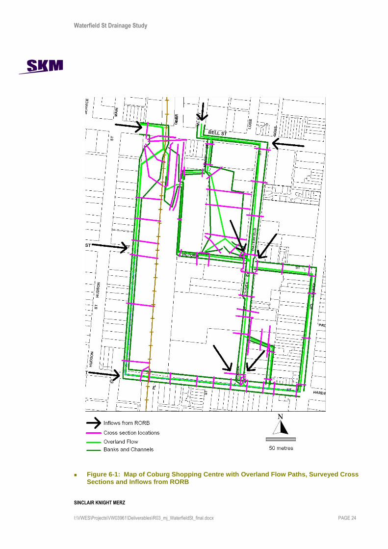
Figure 6-1 shows the overland flow paths throughout the Coburg Shopping Centre and was
developed according to contour lines. It also shows the channel and banks indicating the potential
width of the flow path. The locations of the cross sections were chosen to capture any change of
geometry. They were generally spaced at frequent intervals and normally upstream and
downstream of a corner or bend in the flow path. Cross sections were positioned close together for
areas where the direction of the flow path was uncertain. These include the railway line at Bell
Street, the railway line at Munro Street and the intersection of Waterfield Street and Victoria Street
(near the Coburg Library).
Figure 6-1 also shows the locations of inflow hydrographs adopted from RORB.
Waterfield St Drainage Study
SINCLAIR KNIGHT MERZ
I:\VWES\Projects\VW03961\Deliverables\R03_mj_WaterfieldSt_final.docx PAGE 24
Figure 6-1: Map of Coburg Shopping Centre with Overland Flow Paths, Surveyed Cross Sections and Inflows from RORB

Waterfield St Drainage Study
SINCLAIR KNIGHT MERZ
I:\VWES\Projects\VW03961\Deliverables\R03_mj_WaterfieldSt_final.docx PAGE 25
6.3. Model Setup
The existing drainage network and overland flow paths were modelled in XP Storm. Pipe
diameters and inverts at key locations were based on the detailed site survey. Cross sections of
existing flow paths including street geometries were also based on the detailed site survey. Inflows
at key locations in the catchment for each storm event were adopted from the RORB model and are
shown in Appendix D.
The outlet in the study area is located on the corner of Sydney Road and Munro Street. Since the
outlet is located at the upstream end of the Harding Street drain, the boundary condition at this
location was based on a rating curve. This rating curve was developed by extracting the stage
discharge relationship for the same location (just downstream of Sydney Road) in the Melbourne
Water Harding Street XP storm model. The final stage discharge relationship used at the outlet is
shown in Figure 6-2.
Figure 6-2: Stage Discharge Relationship used at the Outlet in XP Storm
There are a number of locations within the study area where the setup of the model was particularly
critical to ensuring an accurate representation of the flow. These locations include:
The Waterfield Street and Victoria Street intersection (location of Coburg library) -
There is a deep gutter on the north-west corner at the intersection of Waterfield Street and
0
1
2
3
4
5
6
52.5 53 53.5 54 54.5 55
Stage (m AHD)
Flo
w (
m3/s
)
Waterfield St Drainage Study
SINCLAIR KNIGHT MERZ
I:\VWES\Projects\VW03961\Deliverables\R03_mj_WaterfieldSt_final.docx PAGE 26
Victoria Street. When the pipe is at full flow, this gutter holds the flow until the water level
rises above the road crest and then continues along Waterfield Street. Therefore, in XP Storm
the road crest has been set up as a defacto weir.
Munro Street upstream of the railway - As mentioned in Appendix B, the railway line
crossing Munro Street is on an embankment and will prevent any overland flow draining from
west to the east of the catchment. Therefore the runoff from the western part of the catchment
is restricted to either flowing through the council drain under the railway or flowing further
along the railway line out of the study area into the neighbouring catchment. Flow out of the
study area has been modelled as a loss in the XP storm model.
The split of flow over the railway at Bell Street - The railway line crossing Bell Street is
relatively flat. It is difficult to determine whether the flow will:
cross the railway; or
stay on the western side of the railway and subsequently flow through the carpark; or
do both.
To capture this in the XP Storm model, the cross sections across the railway have been divided
into two to represent the east and west side of the railway line. These have been linked to one
another, so that the model can compute which direction the flow will go.
In addition, feedback from Moreland City Council suggested that the section of Sydney Road south
of Munro Street may be acting as storage. The topography along this section is very flat and has a
low point approximately 150 m south of Munro Street. This has been modelled in XP Storm by
including the cross-section in the reach upstream of the outlet. However it should be noted that a
wide, flat storage at this point in the drainage system will not affect upstream flows or velocities,
but it may have an effect on expected peak flows in the Harding Street Main Drain downstream of
Sydney Road.
The remainder of the model was set up in the conventional way with nodes representing inlet pits,
connecting to pipes and the overland flow.
6.4. Results
Plans showing flood extents and flood depths are given in Appendix E.

Waterfield St Drainage Study
SINCLAIR KNIGHT MERZ
I:\VWES\Projects\VW03961\Deliverables\R03_mj_WaterfieldSt_final.docx PAGE 27
7. Existing drainage issues around Coburg shopping centre
Based on the flood extents shown in Appendix E the particular problem areas in the existing
drainage network include:
Potential flooding of residential properties upstream of the railway on Munro Street;
Large flows along Waterfield Street (from the Coburg library to Munro Street) and along
Munro Street (from Waterfield Street to the outlet);
Ponding and uncontrolled overland flow across the carpark west of Waterfield Street and north
of Victoria Street); and
Uncontrolled flow at the Bell Street rail crossing.
The area west of the railway line on Munro Street is considered problematic. This is because the
railway acts as an embankment and the water can only pass downstream through one council drain.
The council drain along Munro Street under the railway is 0.825 m and has a maximum capacity of
1.46 cumecs for a 100 year ARI. There is a maximum flow of approximately 8.3 cumecs upstream
of the railway. Some of this additional flow that cannot fit in the pipe will be stored in the defacto
retarding basin, however, once this is full the flow will encroach on surrounding residential
properties and eventually flow along Loch Street and along the railway at the rear of Loch Street
properties towards another council drain south of the study area. The size and capacity of this drain
is not known. From a site inspection and anecdotal evidence, it is likely that high water levels
occur regularly along the laneway and it can reasonably be concluded that residential properties in
this area are likely to be subject to regular flooding.
The areas that experience the highest velocity and flows are along Waterfield Street (from the
Coburg library to Munro Street) and along Munro Street (from Waterfield Street to the outlet).
These flows pose a risk to pedestrians and drivers. The only known area that experiences flooding
above floor level is the Coburg library, although other unreported properties may be subject to
similar severity of inundation.
The carpark east of Waterfield Street and North of Victoria Street currently experiences
uncontrolled sheet flow. Under existing conditions, it is not considered dangerous as it travels at
low velocities. If redevelopment occurs, however, it is recommended that this uncontrolled flow be
eliminated, particularly if the flow increases. The flow may increase due to redevelopments
upstream such as at the Bell Street railway line and is discussed further below.
There is also a low point in the car park north east of the junction of Waterfield Street and Victoria
Street that causes ponding up to depths of approximately 0.5 m. This may cause risk to pedestrians
or cars parked within the vicinity.

Waterfield St Drainage Study
SINCLAIR KNIGHT MERZ
I:\VWES\Projects\VW03961\Deliverables\R03_mj_WaterfieldSt_final.docx PAGE 28
The direction of flow from Bell St west of the railway crossing is pertinent to the rest of the study
area. Currently the flow splits both east and west of the crossing. If this area is redeveloped in
future, it is critical to understand the downstream impacts of changing this flow split.
If flow is directed west of the railway line, it will result in a larger flood extent at Munro Street
upstream of the railway and may increase the number of residential properties prone to
flooding.
If flow is directed to the east side of the railway line, flows across the carpark will increase, the
severity of flooding of the Coburg library will increase ,and flow along Waterfield Street will
increase.
Therefore, these issues would need to be addressed if redevelopment occurs at the railway crossing
on Bell Street.
In order to address these issues, several options have been developed and tested in the XP Storm
model.

Waterfield St Drainage Study
SINCLAIR KNIGHT MERZ
I:\VWES\Projects\VW03961\Deliverables\R03_mj_WaterfieldSt_final.docx PAGE 29
8. Potential augmentation options
Based on the flood extents shown in Appendix E the problem areas in the existing drainage
network include:
Potential flooding of residential properties upstream of the railway on Munro Street ;
Large flows along Waterfield Street (from the Coburg library to Munro Street) and along
Munro Street (from Waterfield Street to the outlet);
Ponding and uncontrolled overland flow across the carpark west of Waterfield Street and north
of Victoria Street);
Uncontrolled flow at the Bell Street rail crossing.
In order to address these issues, several options have been developed and tested in the model. Each
option has been isolated to determine its effectiveness before being combined with other options.
This process of developing options has taken into consideration that the Coburg shopping centre
may undergo redevelopment in the near future, and a bypass (intended to be undertaken by
VicRoads) has been removed from the public acquisition overlay to the north of Bell Street.
The options tested in this study are as follows :
Option 1 – Pipe augmentation along Munro Street
Option 2 – Relandscaping defacto retarding basin upstream of the Munro Street railway
crossing
Option 3 – Effects of controlled flows east and west of Bell Street railway crossing
Option 4 – Storages underneath the existing car parks
Option 5 – Pipe augmentation through the existing car parks
Option 6 – Reprofiling Waterfield Street
Option 7 – Pipe augmentation along Waterfield Street
Combined Option 1 – Combining options 1, 5, and 7
Combined Option 2 – Combining options 1 and 4
Costing
Cost estimates of the redevelopment works are shown for each option. The adopted cost rates are
generally in accordance with recommended rates from Melbourne Water, which are used for the
Redevelopment Services Schemes and adjusted as necessary to make an allowance for specific
issues. Table 8-1 shows the typical cost factors applied depending on the condition of each section.

Waterfield St Drainage Study
SINCLAIR KNIGHT MERZ
I:\VWES\Projects\VW03961\Deliverables\R03_mj_WaterfieldSt_final.docx PAGE 30
Table 8-1: Cost Factors to apply to Greenfields Reimbursement Rates
Condition Greenfields Factor
Typical Range Median
Greenfield 1 1
Reserve 1.1 – 1.3 1.2
Minor Road 1.2 – 1.6 1.4
Developed Private Properties 1.5 – 2 1.8
Major Road 1.5 – 3 2.5
Pipe Jacking 2.2 – 5 4
The following assumptions have been made as part of the cost estimate:
Relocation of services such as water, wastewater, gas, electricity, and telephony has not been
included in cost estimates. This is partly because the cost of relocation of minor services is
often relatively small, but also because the exact relocations required depends on the exact
alignment chosen. Where significant services will be encountered, such as train and tram rails,
these have been included in costings.
Additional costs of works under rail or tram tracks are often significant, so these have been
taken into account.
Sections that have been tunnelled have been assigned a cost factor of 5.
Tunnelling shafts are assumed to be $25,000 per metre depth. An arbitrary depth of 6 metres
has been assumed.
For major roads, a cost of $100,000 per road has been assumed for traffic management plans.
An estimated railway management/compensation fee of $500,000 has been assumed each time
the proposed works crosses the railway line. It has been assumed that the railway line will not
remain in operation during construction, as there is a risk that the depth of the pipe is not
sufficient to tunnel/pipe jack while the line is still in operation. This assumes that the railway
line is closed so that works can be done over a weekend.
The cost for the railway management/compensation has been based on a weekend closure of the
Upfield Line. It would include:
Gaining approvals from Victrack, Connex and MainCo and their supervision costs
Cost of redirecting passengers by bus around the closure site
Cost of compensation that Connex has to pay the State Government for delays to customers
travel times

Waterfield St Drainage Study
SINCLAIR KNIGHT MERZ
I:\VWES\Projects\VW03961\Deliverables\R03_mj_WaterfieldSt_final.docx PAGE 31
Note that this does not include any rectification to the rail line should it be damaged during
construction.
The scope and quality of the works has not been fully defined and therefore the estimates are not
warranted by SKM. These estimates are typically developed based on supplied costs for common
items from Melbourne Water and SKM experience. The accuracy of the estimates is not expected
to be better than say 50% for the items described in this report. A functional design is
recommended for more detailed budget setting purposes.
Waterfield St Drainage Study
SINCLAIR KNIGHT MERZ
I:\VWES\Projects\VW03961\Deliverables\R03_mj_WaterfieldSt_final.docx PAGE 32
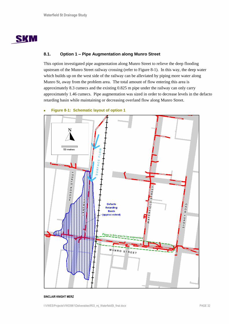
8.1. Option 1 – Pipe Augmentation along Munro Street
This option investigated pipe augmentation along Munro Street to relieve the deep flooding
upstream of the Munro Street railway crossing (refer to Figure 8-1). In this way, the deep water
which builds up on the west side of the railway can be alleviated by piping more water along
Munro St, away from the problem area. The total amount of flow entering this area is
approximately 8.3 cumecs and the existing 0.825 m pipe under the railway can only carry
approximately 1.46 cumecs. Pipe augmentation was sized in order to decrease levels in the defacto
retarding basin while maintaining or decreasing overland flow along Munro Street.
Figure 8-1: Schematic layout of option 1
Waterfield St Drainage Study
SINCLAIR KNIGHT MERZ
I:\VWES\Projects\VW03961\Deliverables\R03_mj_WaterfieldSt_final.docx PAGE 33
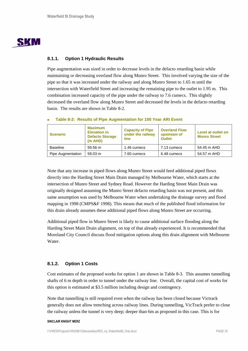
8.1.1. Option 1 Hydraulic Results
Pipe augmentation was sized in order to decrease levels in the defacto retarding basin while
maintaining or decreasing overland flow along Munro Street. This involved varying the size of the
pipe so that it was increased under the railway and along Munro Street to 1.65 m until the
intersection with Waterfield Street and increasing the remaining pipe to the outlet to 1.95 m. This
combination increased capacity of the pipe under the railway to 7.6 cumecs. This slightly
decreased the overland flow along Munro Street and decreased the levels in the defacto retarding
basin. The results are shown in Table 8-2.
Table 8-2: Results of Pipe Augmentation for 100 Year ARI Event
Scenario
Maximum Elevation in Defacto Storage (m AHD)
Capacity of Pipe under the railway line
Overland Flow upstream of Outlet
Level at outlet on Munro Street
Baseline 59.56 m 1.46 cumecs 7.13 cumecs 54.45 m AHD
Pipe Augmentation 59.03 m 7.60 cumecs 6.48 cumecs 54.57 m AHD
Note that any increase in piped flows along Munro Street would feed additional piped flows
directly into the Harding Street Main Drain managed by Melbourne Water, which starts at the
intersection of Munro Street and Sydney Road. However the Harding Street Main Drain was
originally designed assuming the Munro Street defacto retarding basin was not present, and this
same assumption was used by Melbourne Water when undertaking the drainage survey and flood
mapping in 1998 (CMPS&F 1998). This means that much of the published flood information for
this drain already assumes these additional piped flows along Munro Street are occurring.
Additional piped flow in Munro Street is likely to cause additional surface flooding along the
Harding Street Main Drain alignment, on top of that already experienced. It is recommended that
Moreland City Council discuss flood mitigation options along this drain alignment with Melbourne
Water.
8.1.2. Option 1 Costs
Cost estimates of the proposed works for option 1 are shown in Table 8-3. This assumes tunnelling
shafts of 6 m depth in order to tunnel under the railway line. Overall, the capital cost of works for
this option is estimated at $3.5 million including design and contingency.
Note that tunnelling is still required even when the railway has been closed because Victrack
generally does not allow trenching across railway lines. During tunnelling, VicTrack prefer to close
the railway unless the tunnel is very deep; deeper than 6m as proposed in this case. This is for

Waterfield St Drainage Study
SINCLAIR KNIGHT MERZ
I:\VWES\Projects\VW03961\Deliverables\R03_mj_WaterfieldSt_final.docx PAGE 34
construction safety reasons, and also the potential risks and liability involved in passenger trains
passing over an active construction site.
Additional costs of construction under the Sydney Road tram tracks is difficult to estimate directly,
and has therefore been included as a higher construction cost factor of 5, reflecting the highly
complex construction environment near this junction.
Table 8-3: Costs of Proposed Works for Option 1
8.1.3. Option 1 Feasibility
The main construction feasibility issue along Munro Street includes limited space for additional
services. Existing services include:
railway line;
tram tracks on Sydney road;
existing drainage pipeline;
major optic fibres;
high pressure gas mains;
water mains;
waste water mains; and
minor electricity cables.
The proposed works for this option include tunnelling under the railway line, which makes this
option very costly. It also includes crossing the tram tracks on Sydney Road, which is potentially
complex and may affect the timing of construction (e.g. may need to construct during night time or
Total Cost 2,648,293$
Total Cost With Design & Contingency 3,515,129$
Location (Downstream to Upstream) Works Description
Pipeline
Diameter
Length
(m) Factor
Factored
Unit Cost
($/m)
Cost
($)
TOTAL Cost With
Design &
Contingency
($)
Munro St (under railway) Pipe Augmentation 1650 76 5.00 5,065$ 384,940$ 540,263$
Munro St (under railway) u/s tunnelling shaft 6 25,000$ 150,000$ 210,525$
Munro St (under railway) d/s tunnelling shaft 6 25,000$ 150,000$ 210,525$
Munro St (under railway) Railway Management 500,000$ 500,000$
Munro St (railway to Waterfield St) Pipe Augmentation 1650 107 3.00 3,039$ 325,173$ 456,380$
Munro St (Waterfield St to Outlet) Pipe Augmentation 1950 122 5.00 7,690$ 938,180$ 1,316,736$
Munro St (Waterfield St crossing
Sydney Rd to Outlet)Traffic Management Plan 100,000$ 140,350$
Munro St (Waterfield St crossing
Sydney Rd to Outlet)Junction pits x 2 2.00 50,000$ 100,000$ 140,350$

Waterfield St Drainage Study
SINCLAIR KNIGHT MERZ
I:\VWES\Projects\VW03961\Deliverables\R03_mj_WaterfieldSt_final.docx PAGE 35
on the weekend to minimise disruption to public transport). To determine whether there is
adequate space for the proposed works for this option, further investigation will be required at the
functional design stage. Relocation of some of the services listed above may need to be taken into
consideration, however this has not been included in the costs at this stage of the project except
for the railway and tram tracks.

Waterfield St Drainage Study
SINCLAIR KNIGHT MERZ
I:\VWES\Projects\VW03961\Deliverables\R03_mj_WaterfieldSt_final.docx PAGE 36
8.2. Option 2 – Relandscaping Defacto Retarding Basin
This option investigated increasing the size of the defacto retarding basin upstream of the railway
on Munro Street (refer to Figure 8-2). This would allow additional water to be stored in the park
area, consequently reducing the volume of water which would spill out on to neighbouring streets
and properties.
The defacto retarding basin was sized through trial and error to determine the size required to
decrease the water levels in the defacto retarding basin.
Figure 8-2: Schematic layout of option 2

Waterfield St Drainage Study
SINCLAIR KNIGHT MERZ
I:\VWES\Projects\VW03961\Deliverables\R03_mj_WaterfieldSt_final.docx PAGE 37
8.2.1. Option 2 Hydraulic Results
It was found that a storage with a surface area of greater than 30 ha would begin to lower the water
level in the defacto retarding basin. This area assumes that the maximum depth of the storage
coincided with the invert of the existing drain passing under the railway. The results are shown in
Table 8-4.
Table 8-4: Results of Enlarging Defacto Retarding Basin for 100 year ARI event
Scenario Maximum Elevation in Defacto Storage (m AHD)
Overland Flow upstream of Outlet
Baseline 59.56 m 7.13 cumecs
Relandscaping Defacto Storage to 40 ha
59.52 m 7.03 cumecs
Note that this option results in marginally lower flows at the downstream end of the study area.
This would result in a very small reduction in flood levels along the alignment of the Harding
Street Main Drain.
8.2.2. Option 2 Feasibility
From aerial photography the maximum area of storage available is less than 1.5 ha. According to
the model, this size does not have a significant effect on the water levels and is not considered a
cost effective option. Therefore, enlarging the defacto retarding basin to 30 ha is not considered
feasible and consequently a cost has not been provided for this option.

Waterfield St Drainage Study
SINCLAIR KNIGHT MERZ
I:\VWES\Projects\VW03961\Deliverables\R03_mj_WaterfieldSt_final.docx PAGE 38
8.3. Option 3 – Controlled Flows East and West of Bell Street Railway Crossing
This option investigated the impact when all flow is diverted along the east side of railway or when
all the flow is diverted west of the railway (refer to Figure 8-3). This option was tested to
demonstrate the risks that should be considered if redevelopment occurs near the railway line at
Bell Street. For example, if redevelopment occurred which diverted more flow across the railway,
flows through the carpark to Waterfield Street would be increased, exacerbating existing problems.
Likewise, if flow was diverted west of the railway, flow entering the defacto retarding basin
upstream of Munro Street would be increased, exacerbating existing flooding in this area.
Figure 8-3: Schematic layout of option 3

Waterfield St Drainage Study
SINCLAIR KNIGHT MERZ
I:\VWES\Projects\VW03961\Deliverables\R03_mj_WaterfieldSt_final.docx PAGE 39
8.3.1. Option 3 hydraulic results
Table 8-5 shows a summary table of the results of flow being directed east or west of the railway
line at Bell Street.
Table 8-5: Results when flow is directed east or west of railway
Scenario Overland Flow west of Railway (cumecs)
Overland Flow east of Railway (cumecs)
Overland Flow at Outlet (cumecs)
Water Level at Library (m AHD)
Baseline 1.71 1.76 7.13 57.92
Direct all flow west of railway
2.96 0.57 6.03 57.87
Direct all flow east of railway
0.60 2.78 8.13 57.97
Diverting all Flow West of Railway at Bell Street
Overall, if flow is directed along the west side of the railway line the hydraulic results show that:
the flow along the west side of the railway is increased from 1.71 cumecs to 2.96 cumecs.
This will amplify the issues upstream of the railway on Munro Street.
Flows entering the storage will increase from 8.3 cumecs to 9.5 cumecs (these values include
inflows from Bell Street, Victoria Street and Munro Street). This increase in flow would
increase the flood extent and may increase the number of properties prone to flooding.
Therefore, if all flow is directed west of the railway, options need to be developed to cope with the
additional flow and address the issues outlined previously in Section 7.
Diverting all Flow East of Railway at Bell Street
Overall, if flow is directed along the east side of the railway line the hydraulic results show that
flow is increased from 1.76 cumecs to 2.78 cumecs. Directing the flow to the east of the railway
has the following impacts:
It will help alleviate the issues upstream of the railway on Munro Street; however
It will increase uncontrolled flow across the car park;
It will increase flows along Waterfield Street and along Munro Street towards the outlet; and
It will also increase water levels at the Coburg Library and other buildings in the vicinity.
Therefore, if all the flow is directed across the railway, options need to be developed to cope with
the additional flow and address the issues outlined previously in Section 7.

Waterfield St Drainage Study
SINCLAIR KNIGHT MERZ
I:\VWES\Projects\VW03961\Deliverables\R03_mj_WaterfieldSt_final.docx PAGE 40
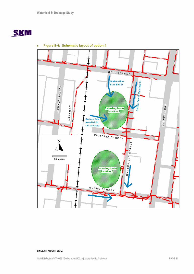
8.4. Option 4 – Storages underneath the Car Park
This option investigated the storage required to decrease the peak flows along Waterfield Street and
along Munro Street towards the outlet. A storage would reduce peak flows by only allowing flows
up to the pipe capacity to pass. All other flows are held in the storage area until the storm has
passed. This eliminates surface flooding immediately downstream of the storage, and reduces
surface flooding further downstream.
Potential storage locations are available throughout the car park. There would be an opportunity to
install storages prior to any redevelopment works. Two locations for the storage were trialled:
north of Victoria Street and south of Victoria Street (refer to Figure 8-4).
A storage located north of Victoria Street could be designed so that overland flow upstream of the
carpark and at the northern end of Waterfield Street could be diverted through the storage. This
would decrease the amount of overland flow across the car park, decrease the water levels near the
library and decrease the peak flow near the outlet.
A storage located south of Victoria Street would capture the overland flow along Waterfield Street
downstream of the library and the overland flow along Munro Street upstream of Waterfield Street.
This would decrease the peak flow near the outlet, however, it would not impact on areas upstream
of the storage. For example, the water levels at the library will not decrease, and there will still be
uncontrolled overland flow across the car park.
The main requirement for the storage is to ensure that the base of the storage is sloped towards the
storage outlet. Pumps would not be required as long as the base of the storage is not below the
invert of the outlet pipe.
Waterfield St Drainage Study
SINCLAIR KNIGHT MERZ
I:\VWES\Projects\VW03961\Deliverables\R03_mj_WaterfieldSt_final.docx PAGE 41
Figure 8-4: Schematic layout of option 4

Waterfield St Drainage Study
SINCLAIR KNIGHT MERZ
I:\VWES\Projects\VW03961\Deliverables\R03_mj_WaterfieldSt_final.docx PAGE 42
8.4.1. Option 4 – Hydraulic Results
Storage North of Victoria Street
The first storage was placed at a node upstream of the library and captured all overland flows along
Waterfield Street upstream of the library and through the carpark. The larger the storage the larger
the decrease in flow and water levels near the library and at the outlet
For the storage to hold all of the overland flow from upstream of the library in a 100 year ARI
event, it needs to be approximately 33,750 m3. For this analysis the dimensions 2.5 ha x 1.35 m
deep were used. The assumed storage depth of 1.35 is feasible, and is based on the existing pipe
invert on the upstream side of Victoria Street.
When the storage is 33,750 m3, the maximum water level in a 100 year event just reaches the door
sill level of the library. The storage is capturing most of the overland flow upstream of the library,
however some overland flow results from the limited capacity of the pipe on Waterfield Street
causing the flow to exit through the pits just outside the library. Increasing the pipe size from
0.675 m to 0.825 m immediately upstream and downstream of the pit outside of the library reduces
the maximum water level in the 100 year ARI event so that it is below the door sill level of the
library.
This option significantly decreases the peak flow upstream of the outlet from 7.1 cumecs to 2.5
cumecs. This will make a significant improvement in flooding issues along the alignment of the
Harding Street Main Drain.
Storage South of Victoria Street
Another storage was investigated in the car park south of Victoria Street. The only issue that this
storage addressed was the large overland flows along Munro Street downstream of Waterfield
Street.
Initially, this storage was sized so that it reduced the overland flow along Munro Street downstream
of Waterfield to at least the crown level of the road for all cross sections. To do this a storage of
65,250 m3 (4.5 ha x 1.45 m deep) was calculated, however, this reduced the overland flow at the
outlet to 0.72 cumecs, which is excessive. A storage of 36,250 m3 (2.5 ha x 1.45 m deep) reduced
the flow upstream of the outlet to 3.2 cumecs, which is a less extreme reduction in flow and
reduces the water level to below the pavement.
In comparison to the storage north of Victoria Street, the storage south of Victoria Street is less
effective. Even with a slightly larger storage, the overland flow upstream of the outlet is greater
than the storage in the north. Additionally, this storage does not alleviate the water levels at the
library.

Waterfield St Drainage Study
SINCLAIR KNIGHT MERZ
I:\VWES\Projects\VW03961\Deliverables\R03_mj_WaterfieldSt_final.docx PAGE 43
The reason that this storage was not as effective in reducing the flow upstream of the outlet is
because the pipes along Munro Street were always full so that the water in the storage was forced
to spill as overland flow rather than flow through the pipes.
This option significantly decreases the peak flow upstream of the outlet from 7.1 cumecs to 3.2
cumecs. This will make a significant improvement in flooding issues along the alignment of the
Harding Street Main Drain.
Table 8-6: Results of Storage Located in the Carpark Upstream of the Library
Scenario
Peak overland flow along Waterfield Street near Library (cumecs)
Peak water level near library (m AHD)
Peak flow upstream of the Outlet (cumecs)
Base Case 5.7 cumecs 57.92 m AHD 7.1 cumecs
Storage (33,750 m3) located north
of Victoria Street 1.7 cumecs 57.76 m AHD 2.5 cumecs
Storage (33,750 m3) and increased
pipes to 0.825 m located north of Victoria Street
0.8 cumecs 57.70 m AHD 2.5 cumecs
Storage (36,250 m3) located south
of Victoria Street 5.7 cumecs 57.92 m AHD 3.2 cumecs
Due to the effectiveness of the storage beneath the car park north of Victoria Street, this option has
been costed and feasibility addressed in the following sections.
8.4.2. Option 4 Costs
The cost of the storage depends on the type of redevelopment that will occur, and the method of
construction. Several different options for constructing a storage were considered:
If a multiple story car park or building was constructed, there would be an opportunity to have
a built in storage at the bottom level. This could consist of a raised floor slab with a cavity of
approximately 1.4 m deep, similar to adding a “half storey” at the bottom of the building. The
cost of such a storage is virtually impossible to estimate for the purposes of this study, as it
depends on construction methods and the relative size of the development. It could be anything
from $1 million to $30 million, or potentially more or less than that.
If development consisted of a single level open car park, a built-in underground storage could
be constructed. One approach would be to construct a series of large pipes beneath the car
park. These would act as a storage when the pipe in Waterfield Street is full. It could then

Waterfield St Drainage Study
SINCLAIR KNIGHT MERZ
I:\VWES\Projects\VW03961\Deliverables\R03_mj_WaterfieldSt_final.docx PAGE 44
backflow into the series of pipes in the car park rather than spill over onto the street. Assuming
an array of 1.35m diameter concrete pipes, the cost of the storage would be of the order of $25
million. Corrugated iron pipes could also be used, but any cost benefit through using cheaper
pipes may be lost due to the greater cover requirements for this type of material.
Alternatively, a built-in storage could be constructed using a modular “off the shelf” system. A
cost estimate for such a storage was provided by Humes Water Solutions. They suggested a
product called the Hume Stormtrap, which is a detention storage system costing $300 per cubic
metre and an additional $200 per cubic meter for installation. Therefore, for a volume of
33,750 m3, the total capital cost is estimated at $16.9 million.
8.4.3. Feasibility of Option 4
The main issues with this option include the cost and the amount of space available.
The redevelopment of central Coburg provides an opportunity to include the drainage and
mitigation works as a condition of development. This would be realistic provided that the cost of
the additional drainage is not excessive compared to the cost of overall site development and the
potential for financial returns from the site. This is discussed further in Section 9.
According to the modelling, a total volume of 33,750m3 is required to prevent flooding of the
library in a 100 year event. In the car park north of Victoria Street a total surface area of
approximately 1 ha is available (150 m long x 72 m wide). Therefore, an average depth of 3.4 m is
required to achieve the volume calculated by the modelling. However, if the storage is designed to
use gravity drainage, the depth available is approximately 1.4 m near the outlet. This results in a
total volume of 16,200 m3 that is available for storage. This does not take into consideration
whether depths across the car park could vary.
Therefore, storage of 33,750 m3 is not feasible under existing conditions.
In any case, this option shows that it is highly effective in reducing flows downstream of the
storage. Although there may not be sufficient space to fit storage of 33,750 m3, there would be
sufficient space for storage to cater for the 1 year, 5 year, 20 year ARI events. Additionally, the
proposed redevelopment of the Coburg shopping centre could provide the opportunity to increase
the available storage volume to further help mitigate a 100 year ARI event. However it should be
noted that a storage sized for a 20 year ARI event may provide little or no benefit in a 100
year ARI event. This is because once a retarding basin is full, it ceases to have any effect on
downstream flows.
In terms of existing services, there is a Yarra Valley Water wastewater pipeline around the
perimeter of the northern car park that needs to be taken into consideration.

Waterfield St Drainage Study
SINCLAIR KNIGHT MERZ
I:\VWES\Projects\VW03961\Deliverables\R03_mj_WaterfieldSt_final.docx PAGE 45
8.5. Option 5 – Pipe Augmentation through Car Park
This option investigated the pipe size required to take all of the peak flow across the carpark in a
100 year ARI event (refer to Figure 8-5). This would minimise the uncontrolled sheet flow and
ponding across the car park. Also, if this area is redeveloped in future, uncontrolled surface flow
may not be desirable, depending on the exact nature of the redevelopment. As a result, some kind
of pipe or channel augmentation may be required.
Two pipes were modelled together for this scenario. One pipe was modelled from the north-west
corner of the carpark to the corner of Victoria and Waterfield Street. The other pipe was modelled
from the west side of the catchment, intersecting with the other pipe at the low point in the car
park.
Figure 8-5: Schematic layout of option 5

Waterfield St Drainage Study
SINCLAIR KNIGHT MERZ
I:\VWES\Projects\VW03961\Deliverables\R03_mj_WaterfieldSt_final.docx PAGE 46
8.5.1. Option 5 – Hydraulic Results
Table 8-7 shows the results of pipe augmentation through the car park. Pipes of 0.750 m diameter
have the capacity to take nearly all the flow (except from the west of the catchment, which has an
overland flow of 0.25 cumecs).
Overall, the results show that pipe augmentation will decrease overland flow throughout the
carpark, however, it will increase flow along Waterfield Street and Munro Street near the outlet.
This indicates that this option needs to be considered in conjunction with another option in order
for it to benefit the catchment. This may include works downstream of the carpark, such as further
pipe augmentation along Waterfield Street or reprofiling of Waterfield Street. These will be
investigated in options 6 and 7.
In addition, the increased flow at the downstream end of the study area means that there will be an
increase in flood levels along the alignment of the Harding Street Main Drain. If any increase in
flows in this drain are considered, it is recommended that potential flood mitigation options for
Harding Street Main Drain be discussed with Melbourne Water. This might involve increasing the
capacity of the existing drain, either through replacement with a larger drain or duplication, or
surface mitigation measures such as detention basins or road remodelling.
Table 8-7: Results of Pipe Augmentation through Car Park for 100 Year ARI
Scenario
Overland Flow across Carpark from North West Corner
Overland Flow across Carpark from West Side
Overland Flow across car park in south east corner
Overland flow along Waterfield Street near Library
Water level near library
Flow upstream of the Outlet
Base Case 0.4 cumecs 1.8 cumecs 1.7 cumecs 5.7 cumecs 57.92 m AHD
6.1 cumecs
Pipe Augmentation (0.750)
0.0 cumecs 0.3 cumecs 0.0 cumecs 6.0 cumecs 57.94 m AHD
7.6 cumecs

Waterfield St Drainage Study
SINCLAIR KNIGHT MERZ
I:\VWES\Projects\VW03961\Deliverables\R03_mj_WaterfieldSt_final.docx PAGE 47
8.5.2. Option 5 – Costs
Cost estimates of the proposed works for option 5 are shown in Table 8-8. Overall, the capital cost
of works for this option is estimated at $0.32 million including design and contingency.
Table 8-8: Costs of Proposed Works for Option 5
8.5.3. Option 5 - Feasibility
This option is considered feasible as there are minimal services within the area. The main concern
is a wastewater pipeline around the perimeter of the northern car park belonging to Yarra Valley
Water that needs to be taken into consideration. The proposed redevelopment of the Coburg
shopping centre would provide a good opportunity for implementing this option.
Total Cost 203,391$
Total Cost With Design & Contingency 315,969$
Location (Downstream to
Upstream) Works Description
Pipeline
Diameter
Length
(m) Factor
Factored
Unit Cost
($/m)
Cost
($)
TOTAL Cost With
Design &
Contingency
($)North West corner to South East
Corner of Car Park Pipe Augmentation 750 139 1.40 433$ 60,131$ 93,414$
West side to Intersection with other
pipePipe Augmentation 750 100 1.40 433$ 43,260$ 67,204$
South east corner of car park Junction pits x 2 2.00 50,000$ 100,000$ 155,350$

Waterfield St Drainage Study
SINCLAIR KNIGHT MERZ
I:\VWES\Projects\VW03961\Deliverables\R03_mj_WaterfieldSt_final.docx PAGE 48
8.6. Option 6 – Reprofiling Waterfield Street
This option investigated reprofiling Waterfield Street so that the street has a flatter crown, thereby
creating more storage for overland flow (refer to Figure 8-6). Currently, along Waterfield Street
north of the library, the road crown is typically 200mm higher than the top of the kerb, with an
average camber of nearly 5%. This is unnecessarily steep, and could be reduced to 1% or 2% in
some areas. This was modelled in XP Storm by changing the cross-sections for each overland flow
reach along Waterfield Street.
Figure 8-6: Schematic layout of option 6

Waterfield St Drainage Study
SINCLAIR KNIGHT MERZ
I:\VWES\Projects\VW03961\Deliverables\R03_mj_WaterfieldSt_final.docx PAGE 49
8.6.1. Option 6 – Hydraulic Results
Table 8-9 shows the results of reprofiling Waterfield Street in a 100 year event. Overall, the flow
along Waterfield Street and Munro Street increases. The flow along Victoria Street decreases
slightly and therefore the water level near the library also decreases. The impact of this option is
minimal and therefore has not been costed.
If the road camber is reduced too much this could affect street drainage in smaller ARI events.
There needs to be sufficient slope available to force surface flow into side entry pits, and to keep
any surface flow concentrated in gutters to avoid any safety issues.
In addition, the marginal increase in flow at the downstream end of the study area means that there
will be a very small increase in flood levels along the alignment of the Harding Street Main Drain.
If any increase in flows in this drain are considered, it is recommended that potential flood
mitigation options for Harding Street Main Drain be discussed with Melbourne Water. This might
involve increasing the capacity of the existing drain, either through replacement with a larger drain
or duplication, or surface mitigation measures such as detention basins or road remodelling.
Table 8-9: Results of Re-Landscaping Waterfield Street in 100 year Event
Scenario
Overland flow along Waterfield Street near Library
Overland Flow along Victoria Street near Library
Water level near library
Flow upstream of the Outlet
Base Case 5.7 cumecs 1.1 cumecs 57.92 m AHD 7.1 cumecs
Reprofiling Waterfield Street
6.0 cumecs 0.8 cumecs 57.90 m AHD 7.2 cumecs
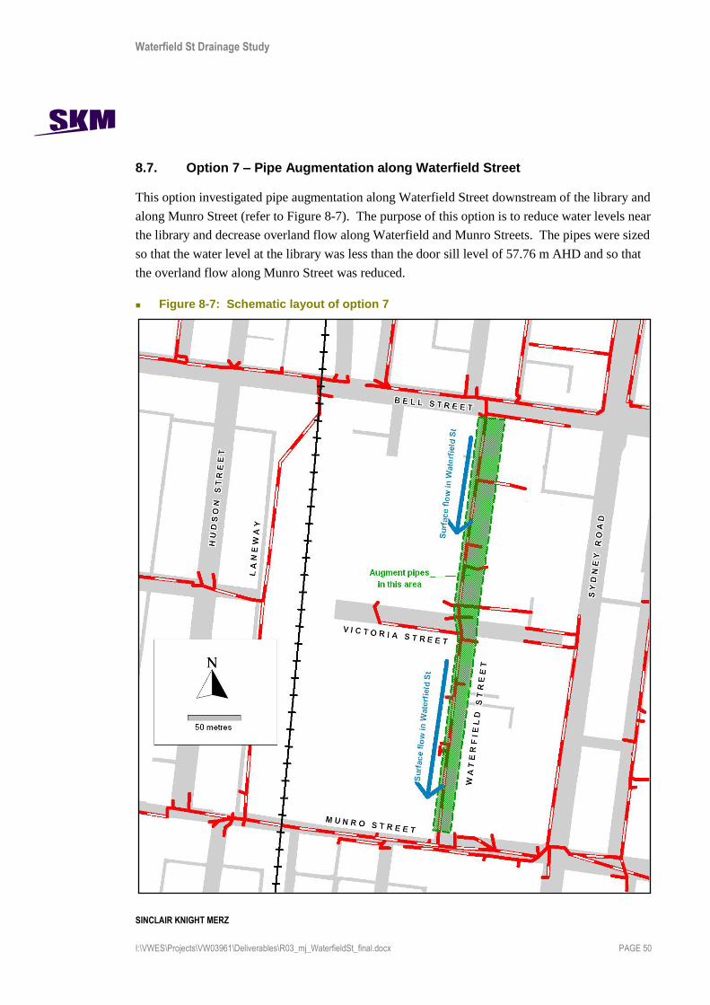
Waterfield St Drainage Study
SINCLAIR KNIGHT MERZ
I:\VWES\Projects\VW03961\Deliverables\R03_mj_WaterfieldSt_final.docx PAGE 50
8.7. Option 7 – Pipe Augmentation along Waterfield Street
This option investigated pipe augmentation along Waterfield Street downstream of the library and
along Munro Street (refer to Figure 8-7). The purpose of this option is to reduce water levels near
the library and decrease overland flow along Waterfield and Munro Streets. The pipes were sized
so that the water level at the library was less than the door sill level of 57.76 m AHD and so that
the overland flow along Munro Street was reduced.
Figure 8-7: Schematic layout of option 7

Waterfield St Drainage Study
SINCLAIR KNIGHT MERZ
I:\VWES\Projects\VW03961\Deliverables\R03_mj_WaterfieldSt_final.docx PAGE 51
8.7.1. Option 7 – Hydraulic Results
Table 8-10 shows the results of enlarging the pipe along Waterfield Street and Munro Street for a
100 year event. Overall, the overland flow near the library was eliminated and the flow upstream
of the outlet was reduced when:
The existing pipe was enlarged from 0.65 m to 1.5 m along Waterfield Street from the library;
and
The existing pipe was enlarged from 1.05 m to 1.5 m along Munro Street, although this does
require additional construction costs for pipe augmentations under the Sydney Road tram
tracks.
This option significantly decreases the peak flow upstream of the outlet from 7.1 cumecs to 3.6
cumecs. This will make a significant improvement in flooding issues along the alignment of the
Harding Street Main Drain.
Table 8-10: Results of Duplicating the Pipe along Waterfield Street and Munro Street
Scenario
Overland flow along Waterfield Street near Library
Overland Flow along Victoria Street near Library
Water level near library
Flow upstream of the Outlet
Base Case 5.7 cumecs 1.1 cumecs 57.92 m AHD 7.1 cumecs
Augmenting Pipe (1.5 m) along Waterfield and Munro Street
0.0 cumecs 0.0 cumecs 57.48 m AHD 3.6 cumecs
8.7.2. Option 7 – Costs
Cost estimates of the proposed works for option 7 are shown in Table 8-8. Overall, the capital cost
of works for this option is estimated at $1.0 million including design and contingency.
Additional costs of construction under the Sydney Road tram tracks is difficult to estimate directly,
and has therefore been included as a higher construction cost factor of 5, reflecting the highly
complex construction environment near this junction.

Waterfield St Drainage Study
SINCLAIR KNIGHT MERZ
I:\VWES\Projects\VW03961\Deliverables\R03_mj_WaterfieldSt_final.docx PAGE 52
Table 8-11: Costs of Proposed Works for Option 7
8.7.3. Option 7 – Feasibility
The main issue along Munro Street include limited space for additional services. Existing services
include:
Tram tracks on Sydney Road;
the existing drainage pipeline;
minor optic fibres along Waterfield Street;
major optic fibres along Munro Street;
minor electricity cables;
high pressure gas mains;
water mains; and
waste water mains.
The proposed works for this option include crossing the tram tracks on Sydney Road, which is
potentially complex and may affect the timing of construction (e.g. may need to construct during
night time or on the weekend to minimise disruption to public transport). Further investigation
may be required along Munro Street at the functional design stage to determine whether there is
adequate space for the proposed works for this option. Relocation of some of the services may
need to be taken into consideration, which has not been included in the costs at this stage of the
project except for the tram tracks on Sydney Road.
Waterfield Street also contains many of the services listed above (except tram tracks) but the
advantage of pipe augmentation along Waterfield Street is the road is bounded by car parks so there
is more likely to be sufficient room for alternative alignments for the proposed works.
Total Cost 659,730$
Total Cost With Design & Contingency 1,024,891$
Location (Downstream to
Upstream) Works Description
Pipeline
Diameter
Length
(m) Factor
Factored
Unit Cost
($/m)
Cost
($)
TOTAL Cost With
Design &
Contingency
($)Waterfield Street (from Victoria
Street to Munro Street) Pipe Augmentation 675 193.52 3.00 792$ 153,268$ 238,102$
Munroe Street (from Waterfield
Street to change in pipe size)Pipe Augmentation 750 16 3.00 921$ 14,736$ 22,892$
Munroe Street (from change in pipe
size ot outlet)Pipe Augmentation 1050 119.56 5.00 2,440$ 291,726$ 453,197$
Munroe St (Waterfield St crossing
Sydney Rd to Outlet)Traffic Management Plan 100,000$ 155,350$
Length of works Junction pits x 3 3.00 50,000$ 100,000$ 155,350$
this spreadsheet is different to the one in the report?

Waterfield St Drainage Study
SINCLAIR KNIGHT MERZ
I:\VWES\Projects\VW03961\Deliverables\R03_mj_WaterfieldSt_final.docx PAGE 53
8.8. Combined Option 1
This option investigated the combination of some of the more effective options detailed above.
These included:
Pipe Augmentation along Munro Street (under railway) 1.65 m until intersection with
Waterfield Street and 1.95m to outlet;
Pipe Augmentation along Waterfield Street (individual option was 1.5m this was upgraded to
1.65m); and
Pipe Augmentation through the car park (0.750 m).
8.8.1. Combined Option 1 – Hydraulic Results
Table 8-12 shows the results of combining three of the piped options. The combination of options
addresses some of the issues in the catchment such as:
Reduces the flood extent upstream of the railway on Munro Street;
Controls flow through the car park;
Decreases water levels near the library; and
Decreases overland flow along Waterfield and Munro Street.
However, the combination of options mean that some of the pipes need to be resized as each option
influences the results of the other options. Without changing the pipe size, the flows along
Waterfield Street and particularly along Munro Street are increased.
Increasing the pipe size on Waterfield Street to 1.65 m removes the overland flow near the library.
However, the overland flow upstream of the outlet does not decrease significantly from 7.1 cumecs
to 6.1 cumecs, although even this modest decrease in flow will help to alleviate flooding problems
along the Harding Street Main Drain alignment. The combination of piped options means that the
peak flows are being routed too quickly through the catchment with less attenuation than if they
travelled as overland flow.

Waterfield St Drainage Study
SINCLAIR KNIGHT MERZ
I:\VWES\Projects\VW03961\Deliverables\R03_mj_WaterfieldSt_final.docx PAGE 54
Table 8-12: Results of Combining 3 of the Piped Options
Scenario
Overland flow along Waterfield Street near Library
Overland Flow along Victoria Street near Library
Water level near library
Flow upstream of the Outlet
Base Case 5.7 cumecs 1.1 cumecs 57.92 m AHD 7.1 cumecs
Combination of Piped options
1.8 cumecs 8.7 cumecs* 58.44 m AHD* 8.4 cumecs
Piped options with increased pipe diameter on Waterfield Street to 1.65m
0.0 0.0 57.48 m AHD 6.1 cumecs
* Note that there is a large spike in the flow that impacts the results.
8.8.2. Combined Option 1 – Costs
Cost estimates of the proposed works for option 1 are shown in Table 8-13. Overall, the capital
cost of works for this option is estimated at $4.8 million.
Table 8-13: Costs of Proposed Works for Combined Option 1
Option Cost Total Cost with Design and Contingency
Pipe augmentation along Munro Street
$2.6 M $3.5 M
Pipe augmentation along Waterfield Street
$0.7 M $1.0 M
Pipe Augmentation through car park
$0.2 M $0.3 M
TOTAL $3.5 M $4.8 M
8.8.3. Combined Option 1 – Feasibility
The main issue along Munro Street include limited space for additional services. Existing services
include:
railway line;
tram tracks on Sydney road;
existing drainage pipeline;
minor optic fibres along Waterfield Street;

Waterfield St Drainage Study
SINCLAIR KNIGHT MERZ
I:\VWES\Projects\VW03961\Deliverables\R03_mj_WaterfieldSt_final.docx PAGE 55
major optic fibres along Munro Street;
high pressure gas mains;
water mains;
waste water mains; and
electricity cables,.
The proposed works for this option include tunnelling under the railway line, which makes this
option very costly. It also includes crossing the tram tracks on Sydney Road, which is potentially
complex and may affect the timing of construction (e.g. may need to construct during night time or
on the weekend to minimise disruption to public transport). Further investigation may be required
along Munro Street at the functional design stage to determine whether there is adequate space for
the proposed works for this option. Relocation of some of the services may need to be taken into
consideration, however, this has not been included in the costs at this stage of the project.
Waterfield Street also contains many of the services listed above (except tram tracks and railway
line) but the advantage of pipe augmentation along Waterfield Street is the road is bounded by car
parks so there is more likely to be sufficient room for alternative alignments for the proposed
works.

Waterfield St Drainage Study
SINCLAIR KNIGHT MERZ
I:\VWES\Projects\VW03961\Deliverables\R03_mj_WaterfieldSt_final.docx PAGE 56
8.9. Combined Option 2
In light of the results presented in Table 8-12, a different combination of options has been
investigated. This includes:
Pipe augmentation along Munro Street (under railway) 1.65 m until intersection with
Waterfield Street and 1.95m to outlet ; and
33,750 m3 of storage beneath car park north of Victoria Street (requiring a very extensive
footprint area).
8.9.1. Hydraulic Results
Table 8-14 shows the results of combining the above options. The combination of options is highly
effective at addressing most of the flooding issues in the catchment such as:
Reduces the flood extent upstream of the railway on Munro Street;
Controls flow and ponding through the car park;
Decreases water levels near the library; and
Decreases overland flow along Waterfield and Munro Street.
The flow upstream of the outlet is reduced significantly from 7.1 cumecs to 2.8 cumecs. This
decrease in flow will significantly reduce flooding problems along the Harding Street Main Drain
alignment.
Table 8-14: Results of Combined Option 2
Scenario
Water Level in Defacto Retarding Basin (m AHD)
Overland flow along Waterfield Street near Library
Water level near library (m AHD)
Flow upstream of the Outlet
Base Case 59.56 m AHD 5.7 cumecs 57.92 m AHD 7.1 cumecs
Storage (1.35m deep by 2.5 ha) located north of Victoria Street and pipe augmentation along Munro Street
59.03 m AHD 0.8 cumecs 57.70 m AHD 2.8 cumecs
8.9.2. Combined Option 2 – Costs
Cost estimates of the proposed works for option 1 are shown in Table 8-13. Overall, the capital
cost of works for this option is estimated at $19.8 million.

Waterfield St Drainage Study
SINCLAIR KNIGHT MERZ
I:\VWES\Projects\VW03961\Deliverables\R03_mj_WaterfieldSt_final.docx PAGE 57
Table 8-15: Costs of Proposed Works for Combined Option 2
Option Cost Total Cost with Design and Contingency
Pipe Augmentation along Munro Street
$2.6 M $3.5 M
Storage beneath Car Park Not known $16.9 M
TOTAL Not known $20.4 M
8.9.3. Combined Option 2 – Feasibility
The main issue with this combined option is the extremely high cost of the storage and the space
required for the storage.
As discussed in Section 8.4.3 the redevelopment of central Coburg provides an opportunity to
include the drainage and mitigation works as a condition of development. This would be realistic
provided that the cost of the additional drainage is not excessive compared to the cost of overall
site development and the potential for financial returns from the site. This is discussed further in
Section 9.
According to the modelling, a total volume of 33,750m3 is required to prevent flooding of the
library in a 100 year event. In the car park north of Victoria Street a total volume of approximately
16,200 m3 is available for storage, therefore storage of 33,750 m
3 is not feasible under existing
conditions. It should be noted that a storage sized for a lesser ARI event will be
proportionally cheaper, but it may provide little or no benefit in a 100 year ARI event.
In any case, this option shows that it is highly effective in reducing flows downstream of the
storage. Although there may not be sufficient space to fit storage of 33,750 m3, there would be
sufficient space for storage to cater for the 1 year, 5 year, 20 year ARI events and storage in this
location of a smaller size would still help alleviate some of the flooding issues in a 100 year event.
Additionally, the proposed redevelopment of the Coburg shopping centre could provide the
opportunity to increase the available storage volume to further help mitigate a 100 year ARI event.
The main issue along Munro Street include limited space for additional services. Existing services
include:
railway line;
tram tracks on Sydney road;
existing drainage pipeline;
major optic fibres;
high pressure gas mains;

Waterfield St Drainage Study
SINCLAIR KNIGHT MERZ
I:\VWES\Projects\VW03961\Deliverables\R03_mj_WaterfieldSt_final.docx PAGE 58
water mains;
waste water mains; and
electricity cables.
The proposed works for this option include tunnelling under the railway line, which makes this
option very costly. It also includes crossing the tram tracks on Sydney Road, which is potentially
complex and may affect the timing of construction (e.g. may need to construct during night time or
on the weekend to minimise disruption to public transport). To determine whether there is
adequate space for the proposed works for this option, further investigation will be required at the
functional design stage. Relocation of some of the services may need to be taken into
consideration, however, this has not been included in the costs at this stage of the project.

Waterfield St Drainage Study
SINCLAIR KNIGHT MERZ
I:\VWES\Projects\VW03961\Deliverables\R03_mj_WaterfieldSt_final.docx PAGE 59
9. Developer Contribution Strategies for Drainage and Flood Mitigation Works
There are three key issues which combine to make it difficult to create an equitable strategy for
determining drainage works contributions:
It is expected that the development of central Coburg will be on a large scale, and will cover
most of the areas where flood mitigation works are required.
It is expected that development works will be undertaken by several different organisations,
and properties where mitigation works may be required are owned by several different owners.
The drainage works are required to address pre-existing drainage problems, because central
Coburg already has a very high impervious fraction, and development is not likely to change
this. Developers are likely to resist having to contribute significant costs for drainage works
required to fix flooding problems caused by others. Nevertheless, most developers would be
willing to assist in some way, as the alleviation of flooding problems may increase the value of
their property.
9.1. Types of strategies
There is a range of strategies available to determine appropriate developer contributions for
drainage and flood mitigation works. Some of these strategies include:
Impervious fraction – if a development is increasing the impervious fraction of a catchment,
it must be increasing the volume of runoff within a catchment. A developer can then contribute
toward the portion of the drainage works which are required to deal with the additional runoff.
This can be implemented as part of a developer contribution plan included in the council
planning scheme, or can simply be included as a requirement on any development permit in
the area.
This is the most common strategy for determining developer contributions toward drainage
works. Melbourne Water has adopted this strategy for many drainage schemes around
Melbourne, including both greenfield sites and redevelopment areas. However, this strategy is
not appropriate in the current case because the impervious fraction of central Coburg is already
extremely high, and further development is unlikely to change it.
Upstream works offset – In some situations, it may be very difficult or expensive to construct
drainage works within a development which help to mitigate the impact of the development on
the drainage system. As an alternative, there may be opportunities to implement works

Waterfield St Drainage Study
SINCLAIR KNIGHT MERZ
I:\VWES\Projects\VW03961\Deliverables\R03_mj_WaterfieldSt_final.docx PAGE 60
upstream of a development which may have a similar effect, but are much cheaper. For
example, if a development were to produce significant extra flood flows, it may be easier for
the developer to construct retarding basins upstream of the development, so that the additional
flows have no net effect.
This strategy is not appropriate in the current case because the proposed developments within
Coburg are unlikely to actually increase flood flows, and there is virtually no land available
upstream for additional drainage works.
On site land offset – In some urban areas, large developments are required to include a given
area of public open space. It may be possible to allow the developer to use this open space as a
retarding basin, yet keep the land open to public use.
This strategy may be possible in this case, but given the scale of the required retarding basins
and the value of land in central Coburg, this strategy is unlikely to be feasible.
Land swap – In some cases, a developer may own other land in a catchment which could be
swapped to allow this land to be used for flood retardation or other flood mitigation works, and
could also double as public open space.
Given the relatively small catchment size in this case, it is unlikely that this strategy will be
feasible.
9.2. Method of implementing drainage contribution charges
Contributions toward the costs of these drainage works can be obtained in a variety of different
ways. The three most appropriate methods in this situation would be:
Create a developer contribution plan, and incorporate that plan into the council planning
scheme;
Include the necessary charges as a requirement of planning / building permits within the study
area; or
Where a development covers a location where drainage works are required, include the actual
works as a requirement of building permits, with the developer funding a proportion of the
works equivalent to the contribution charges.
All of these options will require that detailed planning of the required works be undertaken to
determine the necessary developer charges (VDPCD 2007), as follows:
Developer charge = Infrastructure cost x Developer funding proportion x Share of usage

Waterfield St Drainage Study
SINCLAIR KNIGHT MERZ
I:\VWES\Projects\VW03961\Deliverables\R03_mj_WaterfieldSt_final.docx PAGE 61
Where Infrastructure cost = the total cost of the drainage works in the study area;
Developer funding proportion = proportion of the total infrastructure cost that council
intends to recover through developer charges
Share of usage = the share of usage or benefit that can be attributed to any one
development
Determining the total cost of the drainage works will require a more detailed design of the works,
with costings prepared in more detail than was provided in this study. Potentially this could be
undertaken in conjunction with developers, as the exact costs of the required drainage works in
central Coburg will be heavily dependent on the detailed design of the proposed development
works. For this reason, a collaborative approach with individual developers is essential.
Council needs to determine how much of the works should be funded by developments, and how
much should be funded through other sources such as external grants.
In addition, the share of usage or benefit needs to be carefully considered. In the case of upgrades
to drainage systems, the share of usage is usually determined based on proportion of additional
drainage flow contributed by each new development. However, as previously noted the drainage
problems in the study area are pre-existing, and any new development is unlikely to change total
flows in the drainage system. Therefore the share of usage in this particular case should be based
on proportion of existing flow contributed by each property.
Having determined the above details, council may wish to implement the contribution plan within
the existing council planning scheme. There are specific guidelines published by the Victorian
Department of Planning and Community Development specifying how a development contribution
plan is to be prepared and implemented. These Development Contribution Guidelines are available
online at www.dse.vic.gov.au.
In addition, Darebin City Council has implemented a large number of development contribution
plans for a wide range of types of infrastructure. For details of these plans, refer to the Darebin
website at www.darebin.vic.gov.au, or to the Darebin planning scheme at www.dse.vic.gov.au.
Implementing a contribution plan as part of the council planning scheme is likely to be the most
robust approach, which may be of benefit should the charges be challenged in a VCAT hearing.
However, council may choose to simply add the relevant charges as a condition of any
development permit in the study area. Because such an approach is less likely to be supported in a
VCAT hearing, a more collaborative approach with developers would be required, with all parties
reaching agreement up-front on what drainage works are required and what proportion of the cost
of the works should be covered by developers.

Waterfield St Drainage Study
SINCLAIR KNIGHT MERZ
I:\VWES\Projects\VW03961\Deliverables\R03_mj_WaterfieldSt_final.docx PAGE 62
Whichever method of implementing contribution charges is adopted, collaboration with developers
is important. A transparent, collaborative approach with the involvement of developers in the
design process is likely to provide the potential for better, more cost-effective drainage solutions to
be implemented which complement the proposed development of the area, rather than the drainage
works becoming a constraint or limitation to development.
9.3. Discussion
Given the above issues, an appropriate strategy for determining drainage works contributions could
be to use the ratio of current impervious area of the land being developed compared to the total
current impervious area of the catchment upstream of the Harding Street Main Drain, starting from
the junction of Harding Street and Sydney Road. This way if a property currently represents, say,
5% of the total impervious area upstream of the Harding Street Main Drain, then development of
this property would require a contribution of 5% of the developer funded portion of the costs of
drainage works in this area.
It may be possible for a developer to offset this contribution by reducing the impervious area of the
fully developed property, through measures such as pervious paving or significant lawn / garden
areas. By adding pervious surfaces to the development, the contribution could be proportionally
reduced. In addition, the contribution could also be reduced if the developer undertakes some of the
required drainage works on that property, with the contribution reduction equal to the cost of the
works they have undertaken.
This option is realistic, provided the cost of the contribution is not excessive compared to the cost
of overall site development and compared to the potential financial returns from the site.
It is recommended that this strategy be considered, and that council undertake a more rigorous
economic study of potential contribution scheme strategies after functional design and costing of
the drainage works is completed.
Also, if such a strategy is implemented, then it is recommended that a detailed analysis of the
catchment should be undertaken to determine current impervious areas using high quality satellite
imagery (such as DigitalGlobe) or remote sensing data. The impervious fraction estimates used for
this study are based on planning scheme zones and site observations, and more detailed estimates
should be obtained if they are to be adopted for calculating developer contributions.

Waterfield St Drainage Study
SINCLAIR KNIGHT MERZ
I:\VWES\Projects\VW03961\Deliverables\R03_mj_WaterfieldSt_final.docx PAGE 63
10. Recommendations
10.1. Recommended Option A
If drainage augmentation works are undertaken in the Coburg shopping centre and cost is not a
limiting factor, it is recommended that the following combined option be considered for
implementation:
Pipe augmentation along Munro Street (under railway);
Retarding basin beneath the car park to the north of Victoria Street.
This option provides the best opportunity for reducing flood levels along Waterfield Street and
Munro Street, reducing the potential for flood damage to properties in the area, especially the
Coburg library, and properties upstream of the railway line on Munro Street. It also removes the
uncontrolled flow and ponding that occurs in the car park.
The total cost of this option is $20.4 million including design and contingency. Details of cost
estimates can be found in section 8.9. It should be noted that a storage sized for a lesser ARI
event will be proportionally cheaper, but it may provide little or no benefit in a 100 year ARI
event.
Any functional or detailed design of drainage augmentation works need to be undertaken in close
consultation with both Moreland City Council and Melbourne Water.
10.2. Recommended Option B
If drainage augmentation works are undertaken in the Coburg shopping centre and cost is a limiting
factor, it is recommended that the following combined option be considered for implementation:
Pipe Augmentation along Munro Street (under railway) of 1.65 m until intersection with
Waterfield Street and 1.95m to outlet;
Pipe Augmentation along Waterfield Street of 1.65m; and
Pipe Augmentation through the car park of 0.750 m.
This option provides a reasonable opportunity for reducing flood levels along Waterfield Street and
Munro Street, reducing the potential for flood damage to properties in the area, especially the
Coburg library, and properties upstream of the railway line on Munro Street. It also reduces and
controls the flow and ponding that occurs in the car park north of Victoria Street.
The total cost of this option is $4.8 million including design and contingency. Details of cost
estimates can be found in section 8.8.

Waterfield St Drainage Study
SINCLAIR KNIGHT MERZ
I:\VWES\Projects\VW03961\Deliverables\R03_mj_WaterfieldSt_final.docx PAGE 64
Any functional or detailed design of drainage augmentation works need to be undertaken in close
consultation with both Moreland City Council and Melbourne Water.
10.3. Comparison of Hydraulic Results for Recommended Options
The hydraulic results for the recommended options are shown below.
Scenario Overland flow along Waterfield Street near Library
Water level near library (m AHD)
Flow upstream of the Outlet
Base Case 5.7 cumecs 57.92 m AHD 7.1 cumecs
Recommended Option A
0.8 cumecs 57.70 m AHD 2.8 cumecs
Recommended Option B
0.0 cumecs 57.48 m AHD 6.1 cumecs
These results show that both options significantly reduce the peak flow and water level near the
library in Waterfield Street. It should be noted that the scale of the reduction in water level is not
critical, as both options reduce levels by more than 200mm which is sufficient to eliminate flooding
of the library. In addition, both options reduce the peak flow at the model outlet, however the
option including a large storage has a significantly larger impact in this respect.
Overall, Recommended Option A gives the best hydraulic results overall, but is significantly more
expensive.
10.4. Other Issues to be Considered
It is recognised that the details of any drainage option implemented will depend on the nature of
redevelopment which is planned for the Coburg shopping centre. Depending on the details of the
redevelopment works, some of the above recommended options may no longer be viable, however
it is recommended that all development works take into account the drainage issues which have
been highlighted in this study, and aim to mitigate flooding along Waterfield and Munro Streets. In
particular, the magnitude of 100 year peak flows throughout the study area need to be considered in
any redevelopment design, including the likely magnitude of surface flows.
In addition, the impact of any works in the vicinity of the Bell St rail crossing be carefully
considered, as this area is critical for determining levels of downstream flooding. The exact split of

Waterfield St Drainage Study
SINCLAIR KNIGHT MERZ
I:\VWES\Projects\VW03961\Deliverables\R03_mj_WaterfieldSt_final.docx PAGE 65
flow in this area can result in additional flows passing along the laneway to the Munro St rail
crossing, and exacerbating flooding issues in this area, or can cause additional flows to pass behind
the Coles supermarket in Waterfield St, exacerbating flooding along Waterfield St and Munro St.
It is strongly recommended that any redevelopment of the Coburg shopping centre include a
detailed drainage strategy for the area, and must include details of works designed to control piped
and overland flow magnitudes and flow paths, and demonstrates how these works will mitigate
flooding issues in the area as identified in this report. This strategy must be prepared in close
consultation with both Moreland City Council and Melbourne Water.
10.5. Consideration of litter and blockages
It should be noted that, in accordance with normal practice, all analysis of the drainage system in
this area is based on the assumption that all flow paths, including pipes, channels, and gutters, are
clean and free of blockages. However, commercial areas such as Coburg tend to produce
significant levels of litter, and site observation and council feedback suggests that littler is a major
issue in this catchment. Litter can block drains and gutters causing additional flooding problems,
however due to the random, unpredictable nature of this problem, no allowance has been made in
this study for blockages due to litter.
It is recommended that any drainage works in the Coburg area include litter traps and, if possible,
water quality improvement works. An existing gross pollutant trap exists on Harding St just
downstream of Sydney Road, and is managed by Melbourne Water, therefore any litter traps and
water quality improvement works need to be designed to complement this existing infrastructure.
Also, it is recommended that any detailed design of drainage works in this area include an
appropriate allowance for blockage due to litter.
10.6. Developer contributions
An appropriate strategy for determining drainage works contributions could be to use the ratio of
current impervious area of the land being developed compared to the total current impervious
area of the catchment upstream of the Harding Street Main Drain, starting from the junction of
Harding Street and Sydney Road.
It is recommended that this strategy be considered, and that council undertake a more rigorous
economic study of potential contribution scheme strategies after functional design and costing of
the drainage works is completed.

Waterfield St Drainage Study
SINCLAIR KNIGHT MERZ
I:\VWES\Projects\VW03961\Deliverables\R03_mj_WaterfieldSt_final.docx PAGE 66
Also, if such a strategy is implemented, then it is recommended that a detailed analysis of the
catchment should be undertaken to determine current impervious areas using high quality satellite
imagery (such as DigitalGlobe) or remote sensing data. The impervious fraction estimates used for
this study are based on planning scheme zones and site observations, and more detailed estimates
should be obtained if they are to be adopted for calculating developer contributions.
As above, it is strongly recommended that any redevelopment of the Coburg shopping centre
include a detailed drainage strategy for the area. Refer to section 10.4.

Waterfield St Drainage Study
SINCLAIR KNIGHT MERZ
I:\VWES\Projects\VW03961\Deliverables\R03_mj_WaterfieldSt_final.docx PAGE 67
11. References
City of Darebin, Darebin Planning Scheme - Development Contributions Plan Overlay (including
Schedule 1), January 2006.
Institution of Engineers, Australia (1997), Australian Rainfall and Runoff – A Guide to Flood
Estimation.
Melbourne Water (2004). Land Development Manual. Melbourne Water, Victoria, 2004
Monash University Department of Civil Engineering, in conjunction with Sinclair Knight Merz
(2007), RORB – Version 6, Runoff Routing Program User Manual, by E.M. Laurenson, R.G. Mein,
and R.J. Nathan, October 2007.
SKM (2006) Harding Street Main Drain – Redevelopment Services Scheme Investigation. SKM for
Melbourne Water, August 2006
VicRoads (1999), Road Design Guidelines – Part 7 (Drainage), Rev 1.7, September 1999.
Victorian Department of Planning and Community Development (VDPCD), Development
Contribution Guidelines, March 2007.

Waterfield St Drainage Study
SINCLAIR KNIGHT MERZ
I:\VWES\Projects\VW03961\Deliverables\R03_mj_WaterfieldSt_final.docx PAGE 68
Appendix A Survey Results

Waterfield St Drainage Study
SINCLAIR KNIGHT MERZ
I:\VWES\Projects\VW03961\Deliverables\R03_mj_WaterfieldSt_final.docx PAGE 69

Waterfield St Drainage Study
SINCLAIR KNIGHT MERZ
I:\VWES\Projects\VW03961\Deliverables\R03_mj_WaterfieldSt_final.docx PAGE 70
Table A-11-1: Surveyed Invert Levels at Selected Locations within Coburg Shopping Centre
A B C
Size 625 650
Depth 1.39 1.41
Size 600 525 525
Depth 1.66 1.55 1.54
Size 750 600 375 300
Depth 1.41 1.29 1.30 0.95
Size 675 675 300
Depth 1.67 1.67 1.40
Size 450 450
Depth 1.22 1.20
Size 750 750 300
Depth 1.75 1.76 1.30
Size 800 750 750
Depth 1.77 1.77 1.73
Size 750 750 450
Depth 1.52 1.48 0.83
Size 750 750 600
Depth 1.25 1.20 1.23
Size 750 300x400 brick drain
Depth 1.0861.55
59.56
58.80
59.04
9 JP 1.07x0.88
10
Open pit
drain 300x400
7 JP
8 JP Large
6 JP 600x600 56.31
5 GP 700x600
4 JP 750x600 57.67
3 GP 800x700 57.86
2 JP 61.28
1 JP 61.65
Inlet
Number Pit Type Internal Size Pit Top RL Outlet

Waterfield St Drainage Study
SINCLAIR KNIGHT MERZ
I:\VWES\Projects\VW03961\Deliverables\R03_mj_WaterfieldSt_final.docx PAGE 71
Figure A-1: Locations of Surveyed Invert Levels and Pipe Diameters

Waterfield St Drainage Study
SINCLAIR KNIGHT MERZ
I:\VWES\Projects\VW03961\Deliverables\R03_mj_WaterfieldSt_final.docx PAGE 72
Appendix B RORB Modelling
B.1 RORB Overview
RORB is a non linear rainfall runoff and streamflow routing model for calculation of flow hydrographs in drainage and stream networks.
The model requires catchments to be subdivided into sub-areas, connected by a series of conceptual reach storages. Design storm rainfall is input to the centroid of each sub-area. Specified losses are then deducted, and the excess routed through the reach network.
Each reach is assumed to have storage characteristics as follows:
S = 3600kQm
Where S is storage (m3);
Q is outflow discharge (m3/s); and
k and m are dimensionless parameters.
The coefficient k is the product of two factors:
K = kc.kr
where kc is an empirical coefficient applicable to the entire catchment, and kr is the relative delay time applicable to each reach.
The relative delay time for each reach, kri, is determined as follows:
kri = Fi*(Li/dav)
where Li is the reach length (km), dav is the average distance along the reach network from each subareas’ centroid to the catchment outlet (km), and Fi is an empirical factor, and a function of reach type as follows:
for natural reaches, Fi=1.0, for excavated but unlined reaches, Fi=1/(3Sc0.25), for lined or piped reaches, Fi=1/(9Sc0.5), and for drowned reaches, Fi=0.0,
where Sc is reach slope (%).
The model is also able to simulate:
lakes, retarding basins and similar storages; and
concentrated and distributed inflows and outflows.
B.2 Design Rainfall Intensities
Design rainfall intensities were determined based on the methods prescribed in Book 2 of the 1997
Edition of Australian Rainfall and Runoff (Reference 7). The Intensity-Frequency-Duration (IFD)
table used for the [waterway/drain name] catchment is shown as Table B-1, and is based on the
following parameters:
1 HR DUR 2 ARI 19.1 mm/hr
12 HR DUR 2 ARI 3.9 mm/hr

Waterfield St Drainage Study
SINCLAIR KNIGHT MERZ
I:\VWES\Projects\VW03961\Deliverables\R03_mj_WaterfieldSt_final.docx PAGE 73
72 HR DUR 2 ARI 1.11 mm/hr
1 HR DUR 50 ARI 39.57 mm/hr
12 HR DUR 50 ARI 7.11 mm/hr
72 HR DUR 50 ARI 2.23 mm/hr
G (skewness) 0.35 mm/hr
F2 Geo factor 2 ARI 4.28
F50 Geo factor 50 ARI 14.97
Table B-1: Intensity-Frequency-Duration Table for Coburg
Duration
Design Rainfalls for Average Recurrence Intervals (Years)
1 2 5 10 20 50 100 200 500
(mm/hr) (mm/hr) (mm/hr) (mm/hr) (mm/hr) (mm/hr) (mm/hr) (mm/hr) (mm/hr)
6m 44.4 59.3 81.9 97.4 118.0 147.7 172.6 199.8 239.6
10m 36.1 48.1 66.0 78.3 94.5 118.0 137.5 158.8 190.0
20m 26.0 34.5 47.0 55.4 66.6 82.7 96.1 110.6 131.7
30m 21.0 27.8 37.6 44.2 53.0 65.6 76.0 87.3 103.7
1hr 14.1 18.6 24.9 29.1 34.7 42.7 49.2 56.3 66.5
2hr 9.2 12.1 15.9 18.4 21.8 26.6 30.5 34.7 40.7
3hr 7.1 9.3 12.2 14.0 16.5 20.0 22.9 25.9 30.3
6hr 4.6 6.0 7.7 8.7 10.2 12.3 14.0 15.7 18.3
12hr 3.0 3.8 4.8 5.5 6.4 7.6 8.6 9.6 11.1
18 hr 2.3 2.9 3.7 4.2 5.0 5.9 6.7 7.6 8.7
24hr 1.9 2.4 3.1 3.5 4.1 5.0 5.7 6.4 7.4
36 hr 1.4 1.8 2.4 2.7 3.2 3.9 4.4 5.0 5.8
48hr 1.1 1.5 1.9 2.2 2.6 3.2 3.7 4.1 4.8
72hr 0.8 1.1 1.4 1.7 2.0 2.4 2.8 3.1 3.7
B.3 Storages
There is one defacto storage in the study area. This is located along the western side of the railway
line upstream of Munro Street. This was modelled in the Harding Street RORB model. The
storage is modelled in RORB using a weir and pipe formula and a stage storage relationship.
The model parameters for this storage were reviewed against survey data to ensure that they were
accurate and able to be adopted for this study. The survey indicated that the lowest contour is
58.81 m AHD and the height of the railway line is 59.74 m AHD, which is consistent with
parameters in the model.
Figure B-1 shows the relationships between stage and storage used in the Harding Street RORB
model. It shows the defacto storage was given an infinitely large stage storage relationship to

Waterfield St Drainage Study
SINCLAIR KNIGHT MERZ
I:\VWES\Projects\VW03961\Deliverables\R03_mj_WaterfieldSt_final.docx PAGE 74
model the fact that any stormwater on the western side of the catchment would pond until it is
discharged through either of the council drains under the railway line. Based on a site inspection, it
was determined that the railway line is on a slight embankment above the level of the surrounding
area and hence will prevent any overland flow draining from west to the east of the catchment.
Therefore the runoff from the western part of the catchment is restricted to the two council drains
under the railway line. One of the council drains goes under the railway line along Munro Street.
The other council drain is located approximately 300 m further south and also goes under the
railway line. This drain is not part of the Harding Street Catchment and therefore flow to this
council drain will need to be modelled as a loss in the system in the detailed hydraulic modelling.
Based on this assessment the stage-storage and storage-discharge curves in the RORB model were
adopted for this investigation.
Figure B-1: Stage Storage relationship used in RORB
B.4 New Sub-Areas
The new sub-areas used in RORB for the study area are shown in Figure B-. The sub-areas from
the Harding Street RORB model were sub-divided to increase the level of detail over the study
area.
55
60
65
70
75
80
85
90
95
100
0 2000 4000 6000 8000 10000 12000
Storage (m3) x100,000
Sta
ge (
m A
HD
)

Waterfield St Drainage Study
SINCLAIR KNIGHT MERZ
I:\VWES\Projects\VW03961\Deliverables\R03_mj_WaterfieldSt_final.docx PAGE 75
Figure B-2: New RORB Sub-Areas for Study Area

Waterfield St Drainage Study
SINCLAIR KNIGHT MERZ
I:\VWES\Projects\VW03961\Deliverables\R03_mj_WaterfieldSt_final.docx PAGE 76
Appendix C Hydraulic Grade Line Analysis

Waterfield St Drainage Study
SINCLAIR KNIGHT MERZ
I:\VWES\Projects\VW03961\Deliverables\R03_mj_WaterfieldSt_final.docx PAGE 77
Figure C-1: HGL of Munro Street
55
56
57
58
59
60
61
62
63
64
65
0 50 100 150 200 250
Chainage (m)
Lev
el
(m A
HD
)
HGL (m AHD)
US Obvert (m AHD)
US Invert (m AHD)
Natural Surface Level (mAHD)

Waterfield St Drainage Study
SINCLAIR KNIGHT MERZ
I:\VWES\Projects\VW03961\Deliverables\R03_mj_WaterfieldSt_final.docx PAGE 78
Figure C-2: HGL of Victoria Street
57
58
59
60
61
62
63
0 10 20 30 40 50 60 70
Chainage (m)
Lev
el
(m A
HD
)
Natural Surface Elevation
HGL (m AHD)
US Obvert (m AHD)
US Invert (m AHD)

Waterfield St Drainage Study
SINCLAIR KNIGHT MERZ
I:\VWES\Projects\VW03961\Deliverables\R03_mj_WaterfieldSt_final.docx PAGE 79
Figure C-3: HGL of McKay Street
60.0
60.5
61.0
61.5
62.0
62.5
63.0
63.5
64.0
64.5
65.0
0 50 100 150 200 250 300 350 400 450
Chainage (m)
Le
ve
l (m
AH
D)
Natural Surface Elevation
HGL (m AHD)
US Obvert (m AHD)
US Invert (m AHD)

Waterfield St Drainage Study
SINCLAIR KNIGHT MERZ
I:\VWES\Projects\VW03961\Deliverables\R03_mj_WaterfieldSt_final.docx PAGE 80
Figure C-4: HGL of Service Street
61
62
63
64
65
66
0 100 200 300 400 500
Chainage (m)
Le
ve
l (m
AH
D)
Natural Surface Elevation
HGL (m AHD)
US Obvert (m AHD)
US Invert (m AHD)

Waterfield St Drainage Study
SINCLAIR KNIGHT MERZ
I:\VWES\Projects\VW03961\Deliverables\R03_mj_WaterfieldSt_final.docx PAGE 81
Figure C-5: HGL of Sutherland Street
60
61
62
63
64
65
66
67
68
69
70
0 50 100 150 200 250 300 350 400 450 500
Chainage (m)
Le
ve
l (m
AH
D)
Natural Surface Elevation
HGL (m AHD)
US Obvert (m AHD)
US Invert (m AHD)

Waterfield St Drainage Study
SINCLAIR KNIGHT MERZ
I:\VWES\Projects\VW03961\Deliverables\R03_mj_WaterfieldSt_final.docx PAGE 82
Figure C-6: HGL of Sydney Road/Bell StreetSystem augmentation works
60
61
62
63
64
65
0 50 100 150 200 250 300
Chainage (m)
Le
ve
l (m
AH
D)
Natural Surface Elevation
HGL (m AHD)
US Obvert (m AHD)
US Invert (m AHD)

Waterfield St Drainage Study
SINCLAIR KNIGHT MERZ
I:\VWES\Projects\VW03961\Deliverables\R03_mj_WaterfieldSt_final.docx PAGE 83
Appendix D XP Storm Inputs
D.1 Hydrographs from RORB
Figure D-1: RORB Hydrographs for the 1 Year, 5 Year, 20 Year and 100 Year Flows at Bell Street Upstream of the Railway Line
Bell Street Upstream Railway
0
0.5
1
1.5
2
2.5
3
3.5
0.5 1 1.16667 1.25 1.33333 1.41667 1.5 1.75 2 2.5 3 4 5.5 7
Time (hr)
Flo
w (
m3/s
)
1 Year ARI
5 Year ARI
20 Year ARI
100 Year ARI

Waterfield St Drainage Study
SINCLAIR KNIGHT MERZ
I:\VWES\Projects\VW03961\Deliverables\R03_mj_WaterfieldSt_final.docx PAGE 84
Figure D-2: RORB Hydrographs for the 1 Year, 5 Year, 20 Year and 100 Year Flows at Victoria Street
Victoria Street
0
0.5
1
1.5
2
2.5
3
0.5 1 1.16667 1.25 1.33333 1.41667 1.5 1.75 2 2.5 3 4 5.5 7
Time (hr)
Flo
w (
m3
/s)
1 Year ARI
5 Year ARI
20 Year ARI
100 Year ARI
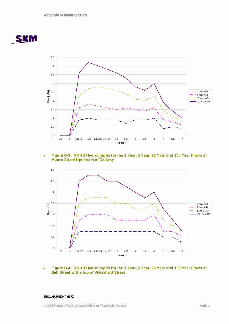
Waterfield St Drainage Study
SINCLAIR KNIGHT MERZ
I:\VWES\Projects\VW03961\Deliverables\R03_mj_WaterfieldSt_final.docx PAGE 85
Figure D-3: RORB Hydrographs for the 1 Year, 5 Year, 20 Year and 100 Year Flows at Munro Street Upstream of Railway
Figure D-4: RORB Hydrographs for the 1 Year, 5 Year, 20 Year and 100 Year Flows at Bell Street at the top of Waterfield Street
Munroe St Upstream of Railway
0
0.5
1
1.5
2
2.5
3
3.5
4
4.5
0.5 1 1.16667 1.25 1.33333 1.41667 1.5 1.75 2 2.5 3 4 5.5 7
Time (hr)
Flo
w (
m3/s
)
1 Year ARI
5 Year ARI
20 Year ARI
100 Year ARI
Bell St @ top of Waterfield St
0
0.2
0.4
0.6
0.8
1
1.2
1.4
0.5 1 1.16667 1.25 1.33333 1.41667 1.5 1.75 2 2.5 3 4 5.5 7
Time (hr)
Flo
w (
m3/s
)
1 Year ARI
5 Year ARI
20 Year ARI
100 Year ARI

Waterfield St Drainage Study
SINCLAIR KNIGHT MERZ
I:\VWES\Projects\VW03961\Deliverables\R03_mj_WaterfieldSt_final.docx PAGE 86
Figure D-5: RORB Hydrographs for the 1 Year, 5 Year, 20 Year and 100 Year Flows at Bell Street at the downstream end of McKay Street
Figure D-6: RORB Hydrographs for the 1 Year, 5 Year, 20 Year and 100 Year Flows for Sub-Areas X and Y
Bell St @ McKay Street
0
0.2
0.4
0.6
0.8
1
1.2
1.4
1.6
1.8
2
0.5 1 1.16667 1.25 1.33333 1.41667 1.5 1.75 2 2.5 3 4 5.5 7
Time (hr)
Flo
w (
m3/s
)
1 Year ARI
5 Year ARI
20 Year ARI
100 Year ARI
X+Y
0
0.5
1
1.5
2
2.5
0.5 1 1.16667 1.25 1.33333 1.41667 1.5 1.75 2 2.5 3 4 5.5 7
Time (hr)
Flo
w (
m3/s
)
1 Year ARI
5 Year ARI
20 Year ARI
100 Year ARI

Waterfield St Drainage Study
SINCLAIR KNIGHT MERZ
I:\VWES\Projects\VW03961\Deliverables\R03_mj_WaterfieldSt_final.docx PAGE 87
Figure D-7: RORB Hydrographs for the 1 Year, 5 Year, 20 Year and 100 Year Flows for Sub-Areas Z and AA
Z+AA
0
0.2
0.4
0.6
0.8
1
1.2
1.4
1.6
0.5 1 1.16667 1.25 1.33333 1.41667 1.5 1.75 2 2.5 3 4 5.5 7
Time (hr)
Flo
w (
m3
/s)
1 Year ARI
5 Year ARI
20 Year ARI
100 Year ARI

Waterfield St Drainage Study
SINCLAIR KNIGHT MERZ
I:\VWES\Projects\VW03961\Deliverables\R03_mj_WaterfieldSt_final.docx PAGE 88
Appendix E Flood extents and depth plans