
WATER SYSTEM FIELD OBSERVATION GUIDELINES rv05302014
14
PUBLIC WATER SYSTEM FIELD OBSERVATION GUIDELINES FOR PROJECTS WITHIN THE PARK CITY WATER SERVICE DISTRICT YEAR 2014
Transcript of WATER SYSTEM FIELD OBSERVATION GUIDELINES rv05302014

PUBLIC WATER SYSTEM
FIELD OBSERVATION
GUIDELINES
FOR PROJECTS WITHIN THE
PARK CITY WATER SERVICE DISTRICT
YEAR 2014

FORWARD
This manual provides information to assist the field representative in his duties of observing the
progress and quality of public water line construction within the Park City Water Service
District, Park City, Utah, and determining if the work is proceeding in accordance with Park City
Design Standards, Construction Specifications and Standard Drawings. The information,
checklists and procedures included in the manual are not all inclusive, but are intended to serve
as guidelines for the performance of periodic construction observations, required sampling and
testing observation by the field representative. It is important that field representatives
contact the Project Manager or the Park City Engineer for clarification if there are any
questions related to the requirements of the Park City Design Standards, Construction
Specifications, and Standard Drawings.

DISINFECTING All new water mains, services, and appurtenances shall be disinfected in accordance with AWWA Standard C651‐05. The method typically employed by the Contractor to disinfect new water distribution systems is to place calcium hypochlorite granules in the pipeline as it is being installed. Reference Park City Design Standards and Construction Specifications, Appendix 703A. The field representative should pay special attention to the following items:
Refer to Table No. 1 of the above referenced Appendix for the number of ounces to be used per pipe diameter and pipe interval to achieve the necessary disinfection concentration.
Active chlorine content of disinfecting solution within water service tubing (CTS) for water services shall not exceed 12%.
Water mains shall be filled slowly to prevent "pushing" the calcium hypochlorite granules to one end of the pipe line. If the new water lines are to be filled by introducing water from the existing water distribution system, via opening the isolation valve between the two systems, the field representative shall monitor the opening of the valve. The field representative shall pay special attention to the following during water system filling by the Contractor: 1. Verify that the static water pressure of the distribution system (typically 40 psi) is
capable of overcoming the static head required to fill the new water line. 2. Be certain a means of releasing air at the high point of the water system to be filled
is provided and is open. 3. The isolation valve shall be opened only slightly (existing water system valves are to
be operated only by Water Operations staff). 4. Listen for water passing the valve. The valve shall be closed immediately if it appears
that the water pressures begin to equalize on each side of the valve. Backflow of chlorinated water into the existing water distribution system must not occur.
After the water mains and services have been filled by the Contractor, the field representative shall sample and test the water for chlorine concentration. Observe the following: 1. Select sampling frequency and locations to achieve representative samples. Typical
locations for samples at water meter services, taps or fire hydrants. The sampling frequency will depend on length of the water line being chlorinated, availability of sampling points, and results of chlorination concentration tests.
The field representative should observe the disinfection of the interior of all pipe, fittings, valves, tapping sleeves, and other materials when existing water mains are cut into or repaired. The Contractor can accomplish this by swabbing the materials with a hypochlorite solution. Reference Park City Design Standards and Construction Specifications, Appendix A.
Remember: Good disinfection practices improve the opportunity for successful bacteriological test results.

WATER SYSTEM FLUSHING
Flushing of the installed water system is to be completed in two steps. The initial flushing is to be performed following installation and disinfection of the water main but prior to hydrostatic testing. The final flushing is to be performed following hydrostatic testing and leakage testing.
INITIAL FLUSHING
The following items should be considered by the field representative and may need to be reviewed with the Park City Engineer:
1. When notified that the Contractor intends to begin the initial flushing but before the Contractor utilizes water contact the Park City Water Department to be certain that water is available from the City for flushing purposes. Inform the Contractor not to begin flushing without authorization (existing water system valves are to be operated only by Water Operations staff).
2. Review with the Contractor the proposed discharge location for flushing operations and the method by which the Contractor intends to control the discharge of chlorinated water from the water system. Fire hydrants are not acceptable points for initial flushing operations. Typically, Contractors will discharge the water into a water truck or tank and haul the water offsite for disposal. Chlorinated water shall not be allowed to be discharged in a manner that it could now onto vegetation or into streams, waterways, storm drains or sanitary sewer systems.
3. Determine the required diameter of opening(s) for discharge from the water line. The opening must be sized to achieve velocities capable of moving dirt and rock through the pipe, approximately 6 to 8 feet per second. Note that required flowrate and opening size(s) referenced in AWWA Table 3 Required Flow and Openings to Flush Pipelines, is based on only 2.5 feet per second velocity at 40 psi pressure. Required opening size will be determined based on site specific available water system pressure to achieve the required velocity.
4. Determine the total volume of water to be expelled from the section of water system being flushed. The entire contents of the water line must be discharged and replaced with new water. To determine the volume required, ensuring that the entire pipe line has been flushed, utilize the following formula:
V=(πd2/4)( L)(7.481); where: V = volume (gallons) π/4 = area d = pipe diameter (feet) π = 3.141
5. If the section of water line to be flushed is very long, making the transport of sediment and rock to the discharge location may be difficult, an intermediate discharge location for flushing should be considered. The end of a fire service line, prior to setting the hydrant, or a properly sized service tap could be utilized.
6. After initial flushing has been completed, perform sampling and testing for "low" chlorination concentration.

FINAL FLUSHING
1. Utilize the same procedure for final flushing as for initial flushing, except that concerns regarding the chlorine concentration of discharge water do not apply.
2. Fire hydrants are to be flushed and can be utilized as flushing locations. 3. Services are to be flushed at the meter vaults. Proper flushing of the service lines is
important since water samples for bacteriological testing are typically taken at the service lines.

HYDROSTATIC TESTING
Hydrostatic testing is required for every section of water main (valve to valve). Testing every section is intended to test both sides of isolation valves to ensure proper functioning of the valve. Prior to hydrostatic testing and leakage testing the water system should be flushed and tested for proper disinfection.
HYDROSTATIC TESTING
The specified hydrostatic test pressure is to be met at the highest elevation in the section of water line being tested. The specified test pressure shall be achieved by means of a Contractor supplied pump/gauge system connected to the pipe. The gauge shall have sufficient increments to enable accurate readings to be taken.
To achieve proper hydrostatic test pressure at the highest elevation of the water line section being tested, consider the locations available for installing the testing apparatus. To determine the required test pressure at the test gauge, utilize the following formula:
Pg = Pr + (Hv – Hg) / 2.31; where: Pg = required gauge pressure reading (psi)
Pr = required test pressure (psi)
Hv = elevation at highest valve (feet)
Hg = elevation at gauge (psi)
Note: 1 psi = 2.31 feet of elevation, or 0.43 psi X elevation difference in feet.
The following items should be considered and may need to be reviewed with the Park City Engineer:
The possibility of requiring/requesting a water valve to be installed in the water main to reduce the pressure difference in the water line to be tested. This may occur when there is a significant difference in elevation between water valves;
The installation of an additional service tap to accommodate proper testing. In achieving the required hydrostatic pressure at the highest elevation of the water line
section being tested, the hydrostatic pressures at the lowest elevation may exceed acceptable pressures for the pipe, valves or fittings. Typically, if the calculated pressure at the lowest elevation exceeds 300 psi, the City Engineer should be notified before testing is performed.

HYDROSTATIC TESTING
The field representative shall perform all sampling for bacteriological testing and deliver samples to the Summit County Health Department (or a pre‐approved state certified laboratory) for analysis. To achieve consistent and representative sampling, the following procedures shall be observed by the field representative:
Select the location and number of samples to be taken. Samples are typically taken at water meter services and ends of the water line. Intervals of 200 feet between sampling locations is preferred.
Procedures for obtaining samples for bacteriological testing of the water system are as follows: 1. Obtain sample bottles from the Public Works Water Department office or Summit
County Health Department, if not available in the office. 2. When sampling, first disinfect or sterilize the discharge area. 3. Open the control valve slowly and allow water to flow for a short period. 4. Close the valve slightly to reduce the flowrate and fill the sample bottle to the fill line.
Place the lid on the sample bottle and seal shut. Note: Be sure to identify the location of the sample bottle before obtaining other samples.
After all samples are taken, complete the identification form and add other pertinent information to each sample bottle. Reference the sample identification form contained in the Report Forms and Checklists section of this manual. Note: Pay special attention to Item No. 2, "Investigative Sample (not included on official records)” on the identification form. Always check this box on the form.

FIELD OBSERVATION REPORT FORMS AND CHECKLISTS
This section includes typical forms checklists that are to be used as generalized guidelines to assist in the verification of the material and dimensional requirements of the Park City Design Standards and Construction Specifications. Field Representatives are to utilize the checklists during water system construction to assist the Contractor in understanding the requirements of the final product and during the final walk‐through to verify consistency with the standards and specifications. Additionally, the fire hydrant inspection forms, illustrating the placement of a fire hydrant in three different terrain conditions, are to be completed during the Final Walk‐through to provide the Park City Engineer with information regarding the hydrant's installed elevation and location relative to the curb and gutter and the auxiliary valve.

FIELD OBSERVATION QUICK CHECKLIST
WATER LINE INSTALLATION:
□ Verify that marking tape and locator wire is installed above the water main in the trench
□ Verify that water main is bedded with approved gravel‐sand material
□ Verify that water main is installed at proper horizontal location (within pavement and
inside of curb & gutter limits) and depth. Require additional survey staking be provided if necessary to determine design grades and curb & gutter alignment
□ Verify that correct polyethylene encasement is provided and properly installed
□ Verify that wax tape coating system is provided and properly installed on all buried bolts
& nuts. Verify the cathodic protection system (if required) is provided and properly
installed.
□ Verify that thrust blocking is of adequate size, extended to undisturbed soil and that the pipe is wrapped with polyethylene before concrete is placed
□ Verify that service taps are at 45 degrees to the main with 2 feet minimum separation
□ Verify that every service corporation stop is open. This can be verified during flushing procedures
□ Verify that water valves are properly set, valve boxes are clear of debris, and that a valve key can be placed on the valve. This must be verified during the final walk‐through

FIELD OBSERVATION QUICK CHECKLIST
FIRE HYDRANT INSTALLATION:
□ Verify that adequate gravel is placed around the fire hydrant base □ Verify that thrust blocking is properly placed and fire hydrant drain ports are not covered
by concrete.
□ Flush fire hydrant drain ports. Close main hydrant valve to the position at which the
drains open and allow flow through the drains under pressure for about ten seconds to flush the drains. Then close hydrant valve completely.
□ Check fire hydrant barrels for drainage. Remove nozzle cap, open hydrant valve, allow
hydrant to run briefly and close hydrant valve. Place palm of hand over nozzle outlet. Drainage should be sufficient to create a suction.
□ Check fire hydrant nozzle caps for thread damage from impact or cross threading
□ Verify that the auxiliary valve is in the wide open position. □ Verify that fire hydrant markers are installed
□ Verify that fire hydrant is properly extended above grade and hydrant pad is properly constructed. See Fire Hydrant Inspection Sheet.

FIELD OBSERVATION QUICK CHECKLIST
WATER METER INSTALLATION:
□ Verify that meter service assembly materials are in accordance with Checklist. See
checklists for specific size water meter.
□ Verify that water meter box is adjusted to grade. See meter box adjustment detail sheet.
□ Verify that water meter box is located properly. Require additional staking as required for
verification.

TYPICAL PROCESS FOR WATER SYSTEM CONSTRUCTION
1. INSTALL WATER MAIN AND FIRE
HYDRANTS
2. INSTALL WATER SERVICES
3. INITIAL FLUSHING OF WATER MAIN
4. INITIAL FLUSHING OF WATER SERVICES
5. PERFORM HYDROSTATIC AND LEAKAGE
TESTING ON WATER MAIN
6. PERFORM HYDROSTATIC AND LEAKAGE
TESTING ON FIRE HYDRANTS & WATER
SERVICES
7. FINAL FLUSHING OF WATER MAIN
8. FINAL FLUSHING OF FIRE HYDRANTS &
WATER SERVICES
9. PERFORM BACTERIOLOGICAL TESTING
10. ALLOW ACTIVATION OF WATER SYSTEM
If the Contractor elects to perform
hydrostatic testing of water services
independently of the water main, Items 3, 5,
7 and 9 will be performed on the water
main prior to installation of the water
services.
If water services are installed after water
main testing, the each services must be
disinfected separately.
Sampling and testing for "high" chlorine
concentration is performed prior to initial
flushing.
Sampling and testing for "low" chlorine
concentration is performed following final
flushing.
Permanent opening of isolation valves upon
receipt of successful bacteriological test
results.
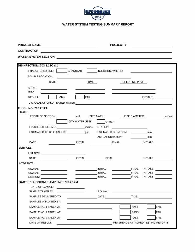
WATER SYSTEM TESTING SUMMARY REPORT
PROJECT #
WATER SYSTEM SECTION
DISINFECTION: 703.2.12C & J
GRANULAR INJECTION, WHERE:
SAMPLE LOCATION:
TIME CHLORINE, PPM
START:
END:
RESULT: PASS
DISPOSAL OF CHLORINATED WATER:
FLUSHING: 703.2.12A MAIN:
LENGTH OF SECTION: PIPE MAT'L: PIPE DIAMETER: inchesfeet
OTHER
FLUSH ORIFICE SIZE: STATION:
ESTIMATED TO BE FLUSHED: gal. ESTIMATED DURATION: min.
min.
INITIAL
ACTUAL DURATION:
FINAL INITIALS DATE:
SERVICES:
DATE: INITIAL FINAL INITIALS
HYDRANTS:
INITIAL FINAL INITIALS
INITIAL FINAL INITIALS
INITIAL FINAL INITIALS
SAMPLE TAKEN BY: P.O. No.:
SAMPLES DELIVERED TO: DATE: TIME:
SAMPLES ANALYZED BY:
SAMPLE NO. 1 TAKEN AT: PASS FAIL
SAMPLE NO. 2 TAKEN AT: PASS FAIL
SAMPLE NO. 3 TAKEN AT: PASS FAIL
DATE OF RESULT: (REFERENCE ATTACHED TESTING REPORT)
PROJECT NAME
CONTRACTOR
TYPE OF CHLORINE:
DATE
FAIL INITIALS
inches
LOT No's:
STATION: STATION: STATION:
BACTERIOLOGICAL SAMPLING: 703.2.12M
CITY WATER USED
DATE OF SAMPLE:

WATER SYSTEM TESTING SUMMARY REPORT (continued)
HYDROSTATIC TEST: 703.2.11
MAIN: DATE: DATE:
TEST PRESSURE @ START: psi @ START: psi
@ 30 min: psi @ 30 min: psi
@ 60 min: psi @ 60 min: psi
@ 90 min: psi @ 90 min: psi
@ FINISH: psi @ FINISH: psi
PASS FAIL PASS FAIL
INITIALS INITIALS
COMMENTS:
SERVICES:
LOTS SERVICED:
DATE: DATE:
TEST PRESSURE @ START: psi @ START: psi
@ 30 min: psi @ 30 min: psi
@ FINISH: psi @ FINISH: psi
PASS FAIL PASS FAIL
INITIALS INITIALS
COMMENTS:
HYDRANTS:
TEST DATE: TEST DATE:
@ START: psi @ START: psi @ START: psi
@ 30 min.: psi @ 30 min.: psi @ 30 min.: psi
@ FINISH: psi @ FINISH: psi @ FINISH: psi
PASS FAIL PASS FAIL PASS FAIL
INITIALS: INITIALS: INITIALS:
COMMENTS:
LEAKAGE TEST: 703.2.11
LENGTH OF SECTION: PIPE MAT'L.: DIAMETER:
LENGTH OF TEST: hours minutes
ACCEPTABLE LOSS, per AWWA C600. TABLE 6: gph per 1000 feet, total gallons
GALLONS USED: gallons
RESULT: PASS FAIL INITIALS
INITIAL TEST RETEST
INITIAL TEST RETEST
STREET & STATION:
TEST DATE:
DATE
STREET & STATION: STREET & STATION:

![Photo field observation [SAME SAME BUT DIFFERENT]](https://static.fdocuments.net/doc/165x107/55aed3e91a28ab975b8b462b/photo-field-observation-same-same-but-different.jpg)


