Water Supply Assessment for South River Dam No. 27
37
Water Supply Assessment for South River Dam No. 27 Madison County, Georgia Prepared for: Georgia State Soil and Water Conservation Commission Prepared by: Schnabel Engineering Jordan Jones and Goulding December 28, 2007
Transcript of Water Supply Assessment for South River Dam No. 27

Water Supply Assessment for South River Dam No. 27
Madison County, Georgia
Prepared for:Georgia State Soil and Water Conservation
Commission
Prepared by:Schnabel Engineering
Jordan Jones and Goulding
December 28, 2007

EXECUTIVE SUMMARY
The Georgia Soil and Water Conservation Commission (GSWCC), in partnership with the Natural Resources Conservation Service (NRCS) and the Georgia Environmental Protection Division (EPD) initiated a study to evaluate whether or not any of the existing watershed dams, designed and constructed under federal laws PL 544 and PL 566, could be modified to serve as water supply reservoirs. The evaluation process went through several iterations, the most recent of which can be found in the Finding Report dated December, 2007 on file with the GSWCC. The Finding Report identified 20 structures that had sufficient potential for relatively high yields with relatively small environmental and infrastructural impacts, when compared to the other projects evaluated. The selected twenty dams were further evaluated to identify project parameters. The following report summarizes the evaluation of South River Dam Number 27, which is located in Madison County, Georgia. For the purposes of this report, the existing normal pool will be raised to impound a water supply pool having a surface area of approximately 992 acres. For convenience, the following summary lists the major findings of this evaluation. This summary should not be utilized as a separate document or in lieu of reading the entire report, including the Appendix.
• Approximately 1515 acres of land will be impacted by the proposed reservoir and dam raising
• Approximately 15 structures will be impacted by the proposed reservoir and dam raising
• 14 county roads will be impacted. • For the modeled conditions, the drought of record in the South River Dam No. 27
basin is the period 1999-2002. For a water supply storage of approximately 7 billion gallons, the safe yield of the reservoir is estimated to be 3.9 mgd.
• Approximately 5 acres of palustrine wetlands will be impacted by the proposed reservoir and dam raising
• Approximately 44 acres of lacustrine/palustrine open waters will be impacted by the proposed reservoir and dam raising
• Approximately 56,060 linear feet of lower perennial streams will be impacted by the proposed reservoir and dam raising
• Approximately 7,669 linear feet of intermittent streams will be impacted by the proposed reservoir and dam raising
• Review of existing cultural resources information identified three cultural resource within the maximum reservoir pool limits of South River 27.
• Review of available information did not indicate any primary or secondary trout streams, or 303(d) / 305(b) listed streams occurring within the maximum reservoir pool limits.
• Project cost is estimated in 2007 dollars at $188,000,000.

PREFACE The results of the analyses presented herein are based upon United States Geological Survey (USGS) quadrangle maps and, therefore, should be utilized for planning purposes only. If the subject project is identified as having a possibility of progressing past this analysis, additional studies will be required. These studies will include but not be limited to detailed environmental evaluations, detailed yield analyses, preliminary engineering design, and detailed cost estimating. These additional studies will be required prior to beginning detailed design work and/or land acquisition. The level of study presented herein shall be considered as a screening tool to evaluate the proposed project relative to other projects. Until further studies are performed, actual yield and costs associated with the entire project cannot be readily determined.

TABLE OF CONTENTS EXECUTIVE SUMMARY PREFACE INTRODUCTION .............................................................................................................. 1 BACKGROUND ................................................................................................................ 1 ENGINEERING FACTORS .............................................................................................. 6 SAFE YIELD ANALYSIS................................................................................................. 9 RESULTS ......................................................................................................................... 12 ENVIRONMENTAL CONSIDERATIONS .................................................................... 14 PROJECT CONSTRUCTION COST ESTIMATE NARRATIVE.................................. 21 APPENDIX....................................................................................................................... 28

07170030.01 -1- Schnabel Engineering South, LLC
INTRODUCTION The project team of Schnabel Engineering South, LLC (Schnabel), Jordan Jones and Golding (JJ&G), Joe Tanner and Associates, and the Law Office of William Thomas Craig were retained by the Georgia State Investment and Financing Commission as the agent for the Georgia Soil and Water Conservation Commission to evaluate 166 existing flood control structures. The subject structures were originally designed and constructed under Federal laws PL 544 and PL 566 to control storm water runoff (flooding) and collect sediment. The goal of this evaluation was to identify impoundments that could be enlarged to provide a relatively reliable water supply. The results of the evaluation were utilized to select twenty of the dams and reservoirs that had potential for relatively high yields with relatively small environmental and infrastructural impacts, when compared to the other projects evaluated. The selected twenty dams were further evaluated to identify project parameters. The additional evaluation included the following:
• More detailed yield analyses • More detailed environmental evaluation • Cost estimation of proposed modifications
The South River Dam Number 27 in Madison County, Georgia was one of the structures selected for further evaluation. BACKGROUND The subject dam, South River Watershed Dam Number 27, is located approximately 2 miles southeast of Ila, Georgia in Madison County. More specifically, the dam is located on the South Fork Broad River about 1-⅓ miles west of the intersection of Rogers Mill Road and Georgia State Route 98. The existing dam was designed in 1965 and constructed in 1967. As designed, the dam had a crest elevation of 723 feet and impounded a reservoir that had a surface area of approximately 51 acres at a normal pool elevation of 690.6 feet. The crest of the emergency spillway was designed to be at elevation 717.4 feet. Figure 1 shows the location of the subject dam within the county as well as a plan view of the existing embankment and emergency spillway. According to the Soil Conservation Service (SCS), now known as the Natural Resources Conservation Service (NRCS), Dam Inventory sheet, the dam was originally designed and constructed as a Class ‘A’ or low-hazard dam. The state Safe Dams program classifies the existing dam as a Category 1 structure. When designed, the emergency spillway (now referred to as an auxiliary spillway) had a two percent chance of operating in any given year. This results in the auxiliary spillway operating during storm events equal to and greater than the 50-year event. With the exception of engineering, land acquisition, and project administration, the dam was completed for a cost of approximately $206,000.


07170030.01 -3- Schnabel Engineering South, LLC
Needs and Demand Evaluation Population projections through the year 2020 were obtained from the Madison County Comprehensive Plan (prepared by the Northeast Georgia Regional Development Center in August 2001). Projections to 2057 were extrapolated based on the assumption of the same constant growth rate that was shown in the Comprehensive Plan. These projections can be seen in Table 1.
Table 1 Population Projection
Year Population Projection
2000 25,7302005 27,8502010 30,5002015 33,6002020 36,700
2025* 39,8002030* 42,9002035* 46,0002040* 49,1002045* 52,2002050* 55,3002055* 58,4002057* 59,460
Data Source: from Madison County Comprehensive Plan *Population calculated based on yearly % growth from 2000-2020
Water demand projections were calculated based on population projections and water withdrawal data for Madison County in 2000. According to the US Census, the population of Madison County was 25,730 in 2000, while the water withdrawal was 1.9 million gallons per day (MGD) based on the document “Water Use in Georgia by County for 2000”, (Information Circular 106, Julia Fanning, USGS, Atlanta, 2003). This withdrawal included large, un-permitted groundwater withdrawal for domestic and commercial usage. Other permitted withdrawals include a 0.25 MGD groundwater withdrawal permit for the City of Oglethorpe and another 0.25 MGD groundwater withdrawal permit for the City of Comer (all numbers are reported in monthly average). The overall usage was calculated to be 75 gallons per day (gpd) per person. This number was used as a constant through 2057 to create water withdrawal projections. The water withdrawal projection for 2057 was calculated to be approximately 4.5 MGD. This figure includes all unaccounted for water (UAW), and the assumption that industrial usage would increase with the increase in Madison County population. Water withdrawal projections are shown in Table 2.

07170030.01 -4- Schnabel Engineering South, LLC
Table 2
Water Withdrawal Projection
Year
Water Withdrawal Projection
(MGD) 2000 1.92005 2.12010 2.32015 2.52020 2.82025 3.02030 3.22035 3.52040 3.72045 3.92050 4.22055 4.42057 4.5
Proximity to Surface Water Intakes Based on the GIS database developed for this project, there is no downstream surface water intake. The closest surface water intake structure is located approximately 10.6 miles to the west on Sandy Creek. This structure is operated by the City of Athens – Clarke County. Figure 2 illustrates the location of the nearest surface water intake location to South River 27.

07170030.01 -5- Schnabel Engineering South, LLC
Figure 2 Distance to Nearest Intake

07170030.01 -6- Schnabel Engineering South, LLC
ENGINEERING FACTORS Proposed Dam The proposed dam, which will incorporate the existing dam, has a crest elevation of 756 feet, an auxiliary spillway elevation of 746 feet, and a normal pool elevation of 743 feet. The proposed dam will impound a reservoir that has a surface area of approximately 743 acres and storage volume of approximately 7,000 million gallons (MG). The configuration of the proposed reservoir is shown in Figure 3. Several engineering assumptions were made pertaining to spillway configuration. The spillway system for the proposed dam was assumed to consist of a principal spillway in the form of a 4’ by 12’ interior dimension reinforced concrete riser with a 48-inch diameter reinforced concrete low-level outlet pipe and an auxiliary spillway in the form of a 480-foot wide reinforced concrete chute spillway with ogee crest. The intent of the principal spillway is to approximate the flows that are being discharged by the current spillway system during the 2 through 100-year storm events. The size of the auxiliary spillway was approximated by estimating the peak inflow that would occur during the Probable Maximum Precipitation (PMP) event and computing the spillway width that would be required to pass the estimated inflow with a given amount of hydraulic head. The available hydraulic head was determined by comparing the drainage basin area to lake surface area. The structures that had a drainage basin area to lake surface area ratio equal to or in excess of 10 were allotted 15 feet of hydraulic head to pass the PMP inflows, while the structures that had a ratio of less than 10 where allotted 10 feet of hydraulic head to pass the PMP inflows. The assumption that the dam would be required to pass the inflows resulting from the PMP storm event is based on the history of the Georgia Department of Natural Resources Environmental Protection Division Safe Dams Program (Safe Dams) reviewing plans for water supply reservoir dams regardless of classification. As such, the dam would generally be required to generally comply with the engineering guidelines established by Safe Dams. Based upon the height of the dam (approximately 80 feet), the dam would be required to safely store and/or pass the inflows from the full PMP event. Additionally, the proposed dam would have a relatively high likelihood of being classified as high-hazard or Class ‘C’ by the NRCS, as well as Safe Dams. The proposed dam and flood pool will:
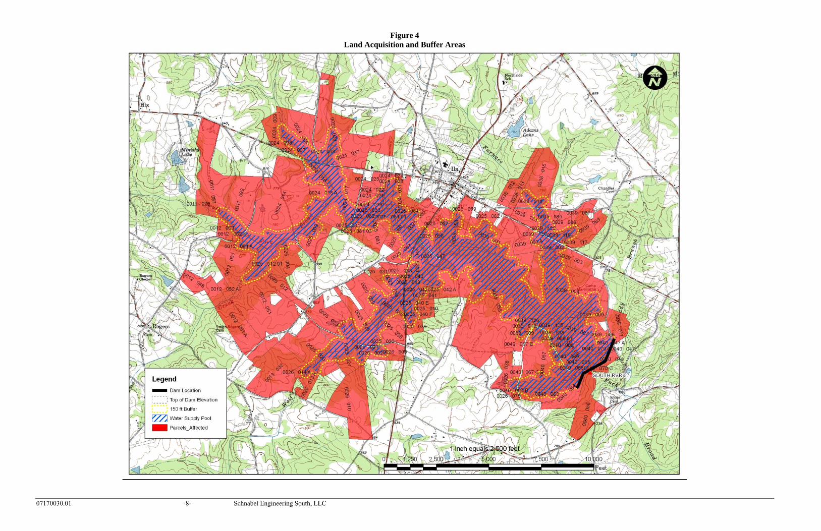
• Impact 15 structures • Require the purchase of 1302 acres from 137 parcels • Require the purchase of 213 acres of easement area for state required buffer • Impact 14 local/county roads
Figure 4 displays the proposed reservoir area as well as the buffer and affected parcels. The 15 affected structures were identified from aerial photographs. The types of structures were not identified on the ground and could be houses, barns, trailers, etc. A more detailed ground survey will be required to determine the type of each structure and the corresponding purchase price of each structure.

07170030.01 -7- Schnabel Engineering South, LLC
Figure 3 Proposed Reservoir Area Map
07170030.01 -8- Schnabel Engineering South, LLC
Figure 4 Land Acquisition and Buffer Areas

07170030.01 -9- Schnabel Engineering South, LLC
SAFE YIELD ANALYSIS Definition Reservoir safe yield is generally defined as the reliable withdrawal rate of water with acceptable quality that can be provided by reservoir storage through the critical drought period. The critical drought period in the State of Georgia is defined as the drought of record and in any given drainage basin can vary depending on reservoir size and other factors. This study was based on the critical drought period from 1999-2002; however, the current drought could possibly exceed the existing drought of record. If this were to occur, the computed yields detailed herein would be reduced. Safe yield in this study was simulated using a constant average annual demand. The justification for this is that while total water demands after declaration of a drought condition are usually less than normal, this situation is typically offset by higher than average demands prior to declaration of the drought condition. Safe yield is dependent upon the storage and hydrologic (rainfall/runoff/evaporation) characteristics of the source and source facilities, the selected critical drought, upstream and downstream permitted withdrawals, and the minimum in-stream flow requirements. Analysis Method The Beaverdam Creek above Elberton (USGS 02188600) and the Broad River above Carolton (USGS 02191300) were selected for use in this analysis. The flows were then used to simulate streamflows in the South Fork Broad River basin. The modeled periods for the Elberton and Carolton gages extend from October 1986 to June 1993 and October 1997 to present, respectively, and includes two major droughts (1986-89, 1999-2002), plus the current drought. The following drainage area was used in the analysis:
• Dam Site (South Fork Broad River): 19.7 mi2 The watershed is shown in Figure 5. The maximum estimated pool level at top of dam was selected during the initial screening phase based on USGS topographic mapping. From that level, a freeboard allowance of 10 feet between the top of dam and the auxiliary spillway was incorporated to pass the spillway design flood (assumed to be the probable maximum flood). Additional depth to maintain existing flood storage volume (4317 Ac-ft, or 1407 MG) was subtracted from the auxiliary spillway elevation to compute the water supply pool elevation used in the analysis of safe yield. Note that more detailed topographic mapping would be needed to more closely approximate the safe yield of the proposed reservoir. Table 3 summarizes the various reservoir elevations and approximate storage volumes. Calculation of stage-area and stage-storage curves is presented as Figure A-1 in the Appendix. Figure 6 below is the stage-storage curve for the reservoir.

07170030.01 -10- Schnabel Engineering South, LLC
Figure 5 Watershed Location Map

07170030.01 -11- Schnabel Engineering South, LLC
Table 3 Summary of Reservoir Data
Stage Elevation Volume (Million Gallons)
Maximum Pool (Top of Dam) 756 13,000 Flood Pool (Auxiliary Spillway Crest) 746 8,400 Water Supply Pool 743 7,000
Figure 6 Stage-Storage Curve
A reservoir operations model was developed to incorporate daily gage data from the selected USGS gage and reservoir shape parameters for estimation of evaporation. The following assumptions were incorporated into the analysis for the estimation of safe yield: Assumptions:
1. Dead storage of 20% of gross reservoir storage was incorporated to allow for sediment storage and poor water quality in lower reservoir strata.
2. Usable water supply storage was assumed to be the water supply pool storage (calculated as noted above) less dead storage.
3. No downstream permitted withdrawals were identified. 4. No upstream withdrawals were identified. 5. For the dam site, minimum in-stream flow of 30/60/40 percent average
annual flow (AAF) was used. This MIF applies as follows: 30% AAF for July through November; 60% AAF for January through April; and 40% AAF for May, June and December.
6. Return flow from wastewater discharges or septic systems was not
660
680
700
720
740
760
0 2000 4000 6000 8000 10000 12000 14000 16000
Volume (MG)
ELEV
ATI
ON
Water Supply Pool EL: 743

07170030.01 -12- Schnabel Engineering South, LLC
considered in the analysis. 7. Evaporation loss was based upon net historical evaporation rates (one
standard deviation above average monthly values) as recorded at the University of Georgia in Athens. Lake evaporation was assumed to be equal to 70% of pan evaporation during each month. Surface area was approximated by a regression equation relating storage to surface area (Figure A-2, Appendix).
8. Streamflow data from the USGS gage was applied in direct proportion of drainage areas to simulate flow into the reservoir and at the diversion location.
9. Total seepage losses would be less than the MIF requirements and, therefore, did not need to be separately considered.
10. Safe yield is that quantity of water that can be provided to meet water demands during the critical drought period.
The attainable safe yield during the analyzed period was found by iteration of the daily mass balance equation:
The trial safe yield value was varied until the reservoir level just reached the dead storage value, and recovery of the reservoir was computed. RESULTS Incorporating the above assumptions, the estimated safe yield of the site was computed. The results of the safe yield analysis are presented in Table 4. It should be noted that these estimated safe yield values are based on USGS topographic mapping. The estimates could vary significantly based on more detailed mapping, which would be required as part of a final safe yield analysis. The table below presents the estimated safe yield and refill time.
Table 4 Safe Yield Summary
Estimated Safe Yield (mgd)
Refill Time* (years)
3.9 5.5 *Refill time is the time from start of drawdown until complete refill to water supply pool
The variation of reservoir elevation over time for the above assumed safe yield is reflected in Figure 7.
Ending Storage = (Beginning Storage) + (Natural Inflow) – (Water Supply) – (Evaporation) – (MIF)

07170030.01 -13- Schnabel Engineering South, LLC
Figure 7
Reservoir Elevation vs. Time Elevation Vs. Time
670
680
690
700
710
720
730
740
750
Oct-86 Oct-89 Oct-92 Oct-95 Oct-98 Oct-01 Oct-04 Oct-07
Ele
vatio
n (fe
et)
Water Supply PoolEL 743
Drought of Record
Dead Storage EL 718
Reservoir Bottom EL 676
Dam Site: South River 27, DA = 19.73 sq.mi.Dam MIF: 30/60/40Water Supply Pool Gross Storage: 7,000 MGSafe Yield = 3.9 mgd
Elevation Vs. Time
670
680
690
700
710
720
730
740
750
Oct-86 Oct-89 Oct-92 Oct-95 Oct-98 Oct-01 Oct-04 Oct-07
Ele
vatio
n (fe
et)
Water Supply PoolEL 743
Drought of Record
Dead Storage EL 718
Reservoir Bottom EL 676
Dam Site: South River 27, DA = 19.73 sq.mi.Dam MIF: 30/60/40Water Supply Pool Gross Storage: 7,000 MGSafe Yield = 3.9 mgd

07170030.01 -14- Schnabel Engineering South, LLC
ENVIRONMENTAL CONSIDERATIONS Preliminary Studies To evaluate the potential environmental impacts, permitting and compensatory mitigation associated with South River 27, preliminary ecological studies were conducted by JJG. These studies consisted of a desktop survey and wetland approximation field surveys to estimate wetlands and streams occurring within the project area. While this evaluation is not sufficient for Clean Water Act Section 404 permitting, field surveys add increased confidence to the desktop evaluation. All estimates of jurisdictional waters, permitting requirements, and compensatory mitigation requirements/cost estimates presented herein are very general and preliminary in nature. Detailed studies would be necessary to definitively determine permitting requirements. Prior to conducting field surveys, desktop evaluations were performed with available data resources including the U.S. Geological Survey 7.5-minute topographic maps and U.S. Fish and Wildlife Service (USFWS) National Wetland Inventory (NWI) maps. JJG ecologists then performed a reconnaissance-level site visit to South River 27 site to verify and supplement the desktop evaluation. Subsequent to field surveys, observations were transcribed into an ArcView GIS database for analysis. Preliminary estimates of jurisdictional waters (i.e., wetlands, streams, open waters) occurring within the South River 27 project area are provided below. Wetlands The Classification of Wetlands and Deepwater Habitats of the United States (Cowardin Classification System) defines the Palustrine System as all nontidal wetlands dominated by trees, shrubs, persistent emergent vegetation, emergent mosses or lichens, and all such wetlands that occur in tidal areas where salinity is less than 0.5 percent. It also includes wetlands lacking such vegetation, but with all of the following four characteristics: 1) area less than 20-acres; 2) the lack of active wave-formed or bedrock shoreline; 3) water depth in the deepest part of basin less than 6.6 feet at low water; and 4) salinity due to ocean-derived salts less than 0.5 percent. The Lacustrine System includes wetlands and deepwater habitats with all of the following characteristics: 1) situated in a topographic depression or a dammed river channel; 2) lacking trees, shrubs, persistent emergent vegetation, emergent mosses or lichens with greater than 30-percent areal coverage; and 3) total area exceeds 20 acres. Wetlands and deepwater habitats less than 20-acres are also included in this system if an active wave-formed or bedrock shoreline feature makes up all or part of the boundary, or if the water depth in the deepest part of the basin exceeds 6.6 feet at low water. Office and field reviews determined that approximately 5 acres of palustrine wetlands and approximately 44 acres of lacustrine/palustrine open waters exist within the South River 27 project area. Cowardin classifications of the wetland systems consist of palustrine emergent with hydrologic regimes ranging from saturated to seasonally flooded.

07170030.01 -15- Schnabel Engineering South, LLC
Streams The Cowardin Classification System defines lower perennial streams as low gradient streams with slow water velocities and substrates comprised mainly of sand and mud. Intermittent streams are defined as streams flowing for only part of the year. When water is not flowing, it may remain in isolated pools or surface water may be absent. Ephemeral streams flow only in direct response to precipitation and do not receive groundwater contributions. Office and field reviews indicate that approximately 56,060 linear feet of lower perennial streams and approximately 7,669 linear feet of intermittent streams are located within the maximum reservoir pool limits of South River 27. Ephemeral streams were not identified due to the preliminary nature of the studies. Refer to Figure 8 for locations of these jurisdictional features. Cultural Resources Review of existing cultural resources information identified three cultural resource sites (Camp Maranatha, two historic houses) within the maximum reservoir pool limits of South River 27. A Phase I Cultural Resources Survey (conducted to the standards of Section 106 of the National Historic Preservation Act) and coordination with Georgia Historic Preservation Division would be required to determine potential Cultural Resources impacts for any proposed reservoir project. Threatened and Endangered Species Review of existing threatened and endangered species information did not identify any known occurrences of protected species within the maximum reservoir pool limits of South River 27. Three protected species are known from Madison County, Georgia and include two faunal and one floral species. Refer to Table 5 for a summary of protected species located in Madison County and potential habitat for these species within the maximum reservoir pool limits.

07170030.01 -16- Schnabel Engineering South, LLC
Figure 8 Jurisdictional Areas Location Map

07170030.01 -17- Schnabel Engineering South, LLC
Table 5
Summary of Protected Species for Madison County, Georgia
Scientific
Name
Vernacular
Name
Federal Status
State Status
Habitat Present (Yes/No)
Preferred Habitat
Fauna
Moxostoma robustum
robust redhorse NA E no
medium to large rivers; shallow riffles to deep flowing water; moderately swift current; mainly over rocky substrate
Notropis scepticus
sandbar shiner NA R no large streams to medium-
sized flowing pools
Flora
Aster georgianus
Georgia aster CS T no
post oak savannah/prairie communities; roadside or utility rights-of-way or other disturbed areas
T= threatened, E= endangered, CS= candidate species, R= rare NA= not applicable Trout Streams Review of available resources did not indicate any primary or secondary trout streams within the maximum reservoir pool limits of South River 27. 303(d) and 305(b) Listed Streams Review of available resources did not indicate any 303(d) or 305(b) listed streams within the maximum reservoir pool limits of South River 27. Section 404/401 Permitting The U.S. Army Corps of Engineers (USACE) regulates the discharge of dredged or fill material into the Nation’s Waters under Section 404 of the Clean Water Act. Construction of an impoundment and flooding jurisdictional streams/wetlands is regulated by the USACE. Two types of permits are available through the USACE: Nationwide and Individual Permits. Nationwide Permits (NWP) have been established previously by the Chief of Engineers for projects that have minimal cumulative impacts to the Nation’s Waters. Examples of the most commonly used NWPs include site development, minor road crossings, maintenance activities, and utility line discharges. Specific criteria and conditions were established that must be satisfied prior to obtaining authorization of a NWP from the USACE. In addition, the Savannah District of the USACE issued Final Nationwide Permit Regional Conditions effective May 11, 2007.

07170030.01 -18- Schnabel Engineering South, LLC
Individual Permits (IP) are required for projects having more than minimal cumulative adverse impacts on the Nation’s waters. The development of a water supply reservoir would typically require an IP. IP’s involve significantly more information, documentation, and coordination with regulatory agencies and are considerably more difficult to acquire than a NWP. Prior to coordination with the USACE regarding the construction of an impoundment, required information would consist of, but not be limited to, the following information:
• Justification of Purpose and Need for the project • Alternatives analysis of other water supply options evaluated to meet the need • Wetland delineation with surveyed boundaries of USACE jurisdictional waters • Phase I cultural resources and protected species surveys • Detailed description of proposed project and proposed impacts to jurisdictional
waters • Detailed analysis of flow releases documented with population analysis and
system modeling • Avoidance and minimization of jurisdictional waters analysis • Identification of adjacent property owners • Development of a conceptual compensatory mitigation plan
Following completion of these items, a complex project meeting would typically be scheduled with the USACE Northern Area Section Office (Morrow, GA) to present the proposed project. Subsequent to the meeting, and if a project is tentatively accepted by the regulatory agencies, formal application and preparation of an IP would start. Following submittal of an IP, the application must be advertised for public comment. The USACE prepares the public notice, which includes detailed applicant information such as site location, proposed impacts, cultural resources, protected species, and proposed mitigation. The public notice would be advertised for 30 days and is also submitted to regulatory agencies including the Environmental Protection Agency (EPA) and USFWS, adjacent property owners, and to the USACE general mailing list. Applicants will be required to respond to inquiries received during the public notice process. Public hearings could be required if substantial adverse comments are received from the coordinating agencies or the public. Additional information and permitting required would consist of a Section 401 Water Quality Certification from the Georgia Environmental Protection Division (EPD). This certification must be issued for an IP to be valid. Depending on the level of impacts associated with the proposed reservoir, an Environmental Assessment or Environmental Impact Statement could be required by the USACE as well. Based on previous project experience, the level of controversy and environmental issues raised during agency and public review, a typical new reservoir project may require permitting times of 5 years or more. The expansion of an existing reservoir could potentially facilitate the Section 404 permitting process when compared to the construction of a new impoundment. This is especially true for issues such as alternatives analysis, avoidance and minimization, and aquatic organism passage in that many or most potential impacts have already occurred. However, the steps of the overall Section 404 permitting process would still need to be

07170030.01 -19- Schnabel Engineering South, LLC
followed, and historically reservoirs have encountered significant regulatory and public challenges, regardless of the presence/absence of an existing impoundment. Compensatory Mitigation To determine the amount mitigation potentially required for jurisdictional impacts within the South River 27, the USACE’s Standard Operating Procedure (SOP) for Compensatory Mitigation (March 2004) was utilized. The SOP uses a series of factors such as location, type, existing condition, type of impact, etc. to generate a multiplying “factor.” That factor is then multiplied by the impact area (acreage or linear footage) to calculate the required mitigation credits. To determine an average factor for jurisdictional areas associated with the South River 27, various conditions observed during the field surveys were utilized. However, it is imperative to note that this document only serves as a guideline if impacts do not exceed 5,000 linear feet of stream or ten acres of wetland impacts. Potential impacts for the South River 27 would significantly exceed this threshold and actual compensatory mitigation requirements would likely be substantially different from SOP estimates. Currently, the USACE Savannah District Office is developing a new SOP for large-scale projects focused on reservoirs. It is anticipated that this SOP would be issued mid-2008. Utilizing the 2004 SOP and the approximated acreage and linear feet of jurisdictional waters located within the South River 27 project area, an estimate of compensatory mitigation credits can be determined. Multiplying factors used for this analysis include: 6.7 for wetland systems, 5.7 for open waters, 12.7 for lower perennial streams, and 7.6 for intermittent streams. This factor was then multiplied by the acreage/ linear footage to determine an estimated number of mitigation credits required. The number of credits was then multiplied by an average credit price to estimate the final estimated compensatory mitigation cost associated with the South River 27. Refer to Table 6 contained in the following section entitled “Project Construction Cost Estimate” for estimated impacts to jurisdictional waters and an estimate of mitigation credits required and associated costs. Stream Buffer Variance The Georgia Erosion and Sedimentation Act of 1975 (GESA), as amended, requires that a 25-foot vegetated buffer be maintained along all state waters. Any land disturbing activities within the buffer would require obtaining a stream buffer variance from the EPD. The local issuing authority is responsible for determining if state waters are on-site and is responsible for determining if a stream buffer variance is required. The GESA has several exemptions including public water system reservoirs. Based on that exemption, reservoir construction would likely be exempt from GESA regulations. Attendant features such as pipelines and roadways, would also be exempt if stream crossings are nearly perpendicular.

07170030.01 -20- Schnabel Engineering South, LLC
EPD Water Withdrawal Permit Georgia EPD requires a permit for withdrawal of 100,000 gallons per day or more of either surface water or ground water. In addition to justification of need for water for up to 50 years in the future, water withdrawal permits typically require the preparation of water conservation, drought contingency, water supply/watershed protection, and reservoir management plans. A public hearing may be required as part of the withdrawal permitting process. EPD requires that its comments on the component plans be addressed before moving forward with issuing the water withdrawal permit. Based on previous permitting experience, a water withdrawal permit can be obtained within 5 to 7 months, depending on EPD’s review time and the extent of their comments. Source Water Protection Plan Amendments to the Federal Safe Drinking Water Act (SDWA) have brought about a new approach for ensuring clean and safe drinking water served by public water supplies in the United States. Management of a drinking water source now requires a Source Water Protection Plan. This plan basically defines watershed management strategies for ensuring that the water supply is not compromised by potential pollutant sources. Typically these sources are unmanaged development, but they can also include industrial sources that can potentially contaminate the water supply. The entity that operates this reservoir for water supply would be required to produce and implement the Plan. The Plan should also address any source water from outside the reservoir watershed that would be used to fill the reservoir, i.e., pumped/storage sources. The cost and schedule for producing a Source Water Assessment and the corresponding Source Water Protection Plan have not been included in any of the estimates presented in the report.

07170030.01 -21- Schnabel Engineering South, LLC
PROJECT CONSTRUCTION COST ESTIMATE NARRATIVE Dam and Reservoir The construction cost estimate for the proposed dam was based upon the general description provided in the background section of the report. Additionally, the following assumptions were made regarding the geometry of the dam.
• Upstream slope of 3H to 1V • Downstream slope of 3H to 1V • Upstream slope wave action protection in the form of riprap from 30 feet below
the crest of the dam to 5 feet below the crest of the dam. Riprap supported by a berm located 30 feet below top of dam.
• Downstream slope having nearly horizontal 12-foot wide berms at 30-foot vertical intervals to control surface water runoff and erosion
• Crest of dam having a width of 25-feet In addition to the above geometric considerations, the following internal drainage configurations were also considered in the estimation of construction costs.
• Chimney drain located at the downstream edge of the crest • Trench drain located at 1/3 the distance from the downstream toe to the crest
A plan view and cross section of the proposed dam is provided in Figures 9 and 10. Contained below are the items estimated to develop the construction cost estimate. We caution that the quantities and associated prices are based upon limited engineering evaluation and will likely change as the project proceeds into detailed evaluation and design. Mobilization and Demobilization Mobilization and demobilization is a lump sum item estimated at 6 percent of the unit rate sum of the construction items. Erosion and Sedimentation Control Erosion and sedimentation control is a lump sum item estimated at 2 percent of the sum of unit rate construction items. Control of Water Control of water is a lump sum item estimated at 3 percent of the sum of unit rate construction items. This item includes the control of both surface water and groundwater and will likely consist of stream diversion, cofferdam construction and maintenance, pumping, and well points, as well as any other means of controlling water during construction.


07170030.01 -24- Schnabel Engineering South, LLC
Clearing Clearing is a unit rate item measured in acres associated with the removal of trees and other vegetation from the reservoir. The estimated area of clearing was assumed to be equal to the surface area of the reservoir at the normal pool elevation. Clearing and Grubbing Clearing and grubbing is a unit rate item measured in acres associated with the removal of trees, other vegetation, and associated root mats in the areas to receive structural fill or concrete. The estimated area of clearing and grubbing was assumed to be equal to the footprint of the proposed dam plus an additional 50-foot perimeter around the proposed dam. Earth Fill Earth Fill is a unit rate item measured in cubic yards. The computed volume of earth fill represents the estimated quantity required to construct the dam as described herein. The estimated quantity was computed using an AutoCad Civil 3D computer model based on the proposed grading and existing topography. In addition to the proposed embankment earth fill, foundation excavation backfill was calculated (see Excavation, Common for details) and added to the embankment earth fill to determine the total quantity of earth fill. Drain Fill Drain Fill is a unit rate item measured in cubic yards. The computed volume of drain fill represents the estimated quantity of fine and coarse-grained drain material required to construct the internal drainage system as described herein. For the purposes of this study, no differentiation was made between fine and coarse drain fill. In addition, the quantity for the trench drain was assumed to be equal to half of the chimney drain quantity. The chimney drain was assumed to have a top elevation equal to the proposed normal pool elevation and a bottom elevation approximated at the limits of the foundation excavation. The chimney drain was assumed to have a width of three feet and run the length of the dam from one abutment, into the floodplain, and up the other abutment tying into residual soils. Excavation, Common Excavation, Common is a unit rate item measured in cubic yards associated with the removal of unsuitable material (soils) within and adjacent to the footprint of the proposed dam. The volume of common excavation was calculated by approximating the surface area of the floodplain within the limits of clearing and grubbing as well as the depth of excavation within the same area. The surface area of the floodplain was approximated using available topographic maps. The depth of excavation was estimated from the boring data included in the design plans for the existing dam.

07170030.01 -25- Schnabel Engineering South, LLC
Riprap Riprap is a unit rate item measured in tons. The computed weight of riprap represents the estimated quantity required to construct the wave-action berm as described herein. Riprap was assumed to be placed on the upstream slope of the dam. The section of riprap was assumed to extend 30 vertical feet, have a thickness of about 2-¾ feet, and traverse the length of the proposed dam. Permanent Turf Establishment Permanent Turf Establishment is a unit rate item measured in acres associated with the establishment of a permanent turf at the conclusion of construction activities for the proposed dam. The estimated area of permanent turf establishment was assumed to be equal to the estimated area of clearing and grubbing. Concrete, Class 4000 Concrete, Class 4000 is a unit rate item measured in cubic yards associated with the construction of the reinforced concrete auxiliary chute spillway. The volume of concrete was estimated by comparing the proposed auxiliary spillway drop in elevation and width to the drops in elevation and widths of constructed reinforced concrete chute spillways. A relationship was developed between the drop in elevation and width of the constructed spillways and the required quantity of concrete. This relationship was applied to the proposed dam to estimate the quantity of concrete. Principal Spillway Reinforced Concrete Pressure Pipe Reinforced Concrete Pressure Pipe (RCPP) is a unit rate item measured in feet. The computed length of RCPP represents the estimated quantity required to construct the principal spillway conduit described herein. The RCPP was assumed to be placed through the base of the proposed dam from the upstream toe to the downstream toe. The diameter of the pipe was assumed to be equal to the diameter of the pipe in the existing dam. Concrete, Class 3000 (mass) Concrete, Class 3000 is a unit rate item measured in cubic yards associated with the construction of the concrete cradle beneath the principal spillway pipe. The concrete cradle was assumed to be designed as a Soil Conservation Service Type A2 cradle and run the length of the principal spillway pipe minus ten feet. Reinforced Concrete Riser The Reinforced Concrete Riser is a lump sum item associated with the construction of the reinforced concrete principal spillway structure. The cost was estimated by comparing the proposed principal spillway riser height to the heights of constructed reinforced concrete riser structures. A relationship was developed between the height of the

07170030.01 -26- Schnabel Engineering South, LLC
constructed spillways and the cost to construct them. This relationship was utilized to estimate the cost of the proposed riser structure. Land Acquisition The costs associated with land acquisitions are unit rate items based upon the number of acres that will need to be purchased at the top-of-dam elevation, the number of acres that will need to be managed for a 150-foot buffer around the normal pool, and the number of houses that will need to be purchased. For the purposes of the buffer management, only the portions of the buffer above top-of-dam elevation were considered. The costs to purchase the land were estimated based upon available records of recent land sales. The cost to manage the buffer was assumed to be 60 percent of the land purchase cost. The cost of each structure impacted was assumed to be $200,000. Roadway Relocation To construct the proposed project, 14 roads will be impacted. These roads may need to be raised, relocated, or modified to accommodate the new reservoir; however, no consideration was given to the relocation of the roads in this study. A more detailed evaluation would need to be performed to evaluate the impact on existing roadways and the associated cost. Compensatory Mitigation The simplest mitigation option is typically purchasing credits from a bank. Compensatory mitigation credits may be purchased from an approved mitigation bank or through the Georgia Land Trust Service Center if a bank is not available within the project area. Based on recent projects, wetland credits range from $7,000-$10,000 per credit and stream credits range from $70-$110 per credit. An option to purchasing credits is to obtain credits by conducting on-site restoration or preservation of jurisdictional waters.

07170030.01 -27- Schnabel Engineering South, LLC
Table 6
South River 27 Estimated Impacts and Overall Mitigation Banking Cost Analysis
Impact Type Estimated Impact
Acres/Linear Feet
Projected Credits Needed
Projected Cost* $90/stream credit
$7,500/wetland credit
Wetland 4.55 A. 30 $225,000 Intermittent Stream
7,669 l.f. 58,284 $5,245,560
Lower Perennial Stream
56,060 l.f. 711,962 $64,076,580
Open Water 44.1 A. 251 $18,825,500 Total 48.65 acres /
63,729 lf 281 wetland / 770,246 stream**
$88,372,640
*Cost is based on recent quotes from banks within the Upper Oconee Basin. Actual banking price may be higher or lower than estimated depending on the date of purchase and credit availability.**Total required credits calculated using the March 2004 Standard Operating Procedure mitigating guidelines established by the US Army Corps of Engineers.
Estimated Project Construction Cost The total project cost is estimated at $188,000,000. Table A-4, located in the appendix, shows an itemized breakdown of the costs associated with enlarging the existing dam and reservoir. These costs are estimates and are based on multiple assumptions.

07170030.01 -28- Schnabel Engineering South, LLC
APPENDIX FIGURES Figure A-1 Stage Storage / Stage Area Curves Figure A-2 Regression Equations for Area to Storage and Depth to Storage Figure A-3 Storage vs. Time and Elevation vs. Time for Assumed Safe Yield TABLE Table A-1 Total Project Opinion of Cost

07170030.01 -29- Schnabel Engineering South, LLC
Figure A-1
Elev. Area Area Inc. Vol.Acres mg/in A-FT A-FT M Gal.
676 0.0 0 0 0 0691 45.8 1 334 334 109720 352.4 10 5853 6187 2016740 873.5 24 12258 18445 6011760 1761.7 48 26352 44797 14599
South River 27
Cumulative Vol
Area and Storage Curves
Area - Elevation Curve
660
680
700
720
740
760
0 200 400 600 800 1000 1200 1400 1600 1800
Area (Acres)
ELEV
ATI
ON
Water Supply Pool EL 743
Storage - Elevation Curve
660
680
700
720
740
760
0 2000 4000 6000 8000 10000 12000 14000 16000
Volume (MG)
ELEV
ATI
ON
Water Supply Pool EL 743

07170030.01 -30- Schnabel Engineering South, LLC
Figure A-2
South River 27
Compute Regression Equation Relating Area to Storage (for Evaporation Calculations)
y = 0.0197x0.8136
R2 = 0.9998
05
101520253035404550
0 5000 10000 15000
Storage (MG)
Are
a (m
g/in
)
Compute Regression Equation Relating Depth to Storage (for Elevation Estimates)
y = 1.0848x0.4354
R2 = 0.9964
0
10
20
30
40
50
60
70
80
0 2000 4000 6000 8000 10000 12000 14000 16000
Storage (mg)
(Ele
v - E
lev
Min
)

07170030.01 -31- Schnabel Engineering South, LLC
Storage Vs. Time
0
1000
2000
3000
4000
5000
6000
7000
8000
Oct-86 Oct-89 Oct-92 Oct-95 Oct-98 Oct-01 Oct-04 Oct-07
Stor
age
(mg)
Figure A-3 South River 27
Elevation Vs. Time
670
680
690
700
710
720
730
740
750
Oct-86 Oct-89 Oct-92 Oct-95 Oct-98 Oct-01 Oct-04 Oct-07
Ele
vatio
n (fe
et)
Water Supply Pool
Drought of
Dead Storage EL
Reservoir Bottom EL
Dam Site: South River 27, DA = 19.73 sq.mi. Dam MIF: 30/60/40 Water Supply Pool Gross Storage: 7,000 MG Safe Yield = 3.9 mgd
Water Supply Pool 7 BG
Drought of Record
Dead Pool Storage 1.4 BG
Dam Site: South River 27, DA = 19.73 sq.mi. Dam MIF: 30/60/40 Water Supply Pool Gross Storage: 7,000 MG Safe Yield = 3.9 mgd

Item . Description of Work Estimated Unit Unit Price AmountNo. Quantity
1. Mobilization and 1 Job Lump Sum $1,676,069Demobilization
2. Erosion & Sediment Control 1 Job Lump Sum $558,690
3. Control of Water 1 Job Lump Sum $838,035
4. Clearing 992 Ac $2,500 $2,480,000
5. Clearing & Grubbing 30 Ac $5,000 $150,000
6. Earth Fill 1,067,334 Cu-Yd $4 $4,269,336
7. Drain Fill 25,181 Cu-Yd $75 $1,888,575
8. Excavation, Common 64,966 Cu-Yd $5 $324,830
9. Riprap 32,018 Ton $75 $2,401,350
10. Permanent Turf Establishment 30 Ac $2,000 $60,000
11. Concrete, Class 4000 (reinforced) 18,438 Cu-Yd $850 $15,672,300
12. Concrete, Class 3000 (mass) 329 Cu-Yd $400 $131,600
13. 48-Inch RCP 773 Feet $500 $386,500
14. Principal Spillway Riser 1 Lump Sum $170,000 $170,000
Dam Construction Cost Estimate $31,007,285
15. Land Acquisition 1,302 Ac $20,000 $26,040,000
16. Easement Acquisition 213 Ac $12,000 $2,556,000
Table A-1
South River Dam No. 27
TOTAL PROJECT OPINION OF COST
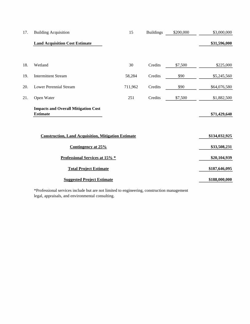
17. Building Acquisition 15 Buildings $200,000 $3,000,000
Land Acquisition Cost Estimate $31,596,000
18. Wetland 30 Credits $7,500 $225,000
19. Intermittent Stream 58,284 Credits $90 $5,245,560
20. Lower Perennial Stream 711,962 Credits $90 $64,076,580
21. Open Water 251 Credits $7,500 $1,882,500
Impacts and Overall Mitigation Cost Estimate $71,429,640
$134,032,925
$33,508,231
$20,104,939
$187,646,095
$188,000,000
*Professional services include but are not limited to engineering, construction managementlegal, appraisals, and environmental consulting.
Suggested Project Estimate
Contingency at 25%
Construction, Land Acquisition, Mitigation Estimate
Professional Services at 15% *
Total Project Estimate