WATER SUPPLY AND DISTRIBUTION - Seattle
24
2012 SEATTLE RESIDENTIAL CODE 603 CHAPTER 29 WATER SUPPLY AND DISTRIBUTION ((SECTION P2901 GENERAL P2901.1 Potable water required. Dwelling units shall be supplied with potable water in the amounts and pressures specified in this chapter . Where a nonpotable water-distribu- tion system is installed, the nonpotable system shall be identi- fied by color marking, metal tags or other appropriate method. Where color is used for marking, purple shall be used to identify municipally reclaimed water, rainwater and graywater distribution systems. Nonpotable outlets that could inadvertently be used for drinking or domestic purposes shall be posted. )) ((SECTION P2902 PROTECTION OF POTABLE WATER SUPPLY P2902.1 General. A potable water supply system shall be designed and installed as to prevent contamination from non- potable liquids, solids or gases being introduced into the pota- ble water supply. Connections shall not be made to a potable water supply in a manner that could contaminate the water supply or provide a cross-connection between the supply and a source of contamination except where approved methods are installed to protect the potable water supply . Cross-con- nections between an individual water supply and a potable public water supply shall be prohibited. P2902.2 Plumbing fixtures . The supply lines and fittings for every plumbing fixture shall be installed so as to prevent backflow. Plumbing fixture fittings shall provide backflow protection in accordance with ASME A112.18.1/CSA B125.1. P2902.3 Backflow protection. A means of protection against backflow shall be provided in accordance with Sections P2902.3.1 through P2902.3.6. Backflow prevention applica- tions shall conform to Table P2902.3, except as specifically stated in Sections P2902.4 through P2902.5.5. P2902.3.1 Air gaps. Air gaps shall comply with ASME A112.1.2 and air gap fittings shall comply with ASME A112.1.3. The minimum air gap shall be measured verti- cally from the lowest end of a water supply outlet to the flood level rim of the fixture or receptor into which such potable water outlets discharge. The minimum required air gap shall be twice the diameter of the effective opening of the outlet, but in no case less than the values specified in Table P2902.3.1. An air gap is required at the discharge point of a relief valve or piping. Air gap devices shall be incorporated in dishwashing and clothes washing appli- ances . P2902.3.2 Atmospheric-type vacuum breakers. Pipe- applied atmospheric-type vacuum breakers shall conform to ASSE 1001 or CSA B64.1.1. Hose-connection vacuum breakers shall conform to ASSE 1011, ASSE 1019, ASSE 1035, ASSE 1052, CSA B64.2, CSA B64.2.1, CSA B64.2.1.1, CSA B64.2.2 or CSA B64.7. These devices shall operate under normal atmospheric pressure when the critical level is installed at the required height. P2902.3.3 Backflow preventer with intermediate atmo- spheric vent. Backflow preventers with intermediate atmospheric vents shall conform to ASSE 1012 or CAN/ CSA B64.3. These devices shall be permitted to be installed where subject to continuous pressure conditions. The relief opening shall discharge by air gap and shall be prevented from being submerged. P2902.3.4 Pressure vacuum breaker assemblies. Pres- sure vacuum breaker assemblies shall conform to ASSE 1020 or CSA B64.1.2. Spill -resistant vacuum breaker assemblies shall comply with ASSE 1056. Th ese assem- blies are designed for installation under cont inuous pres- sure conditions where the critical level is installed at the required height. Pressure vacuum breaker assemblies shall not be installed in locations where spillage could cause damage to the structure. ((TABLE P2902.3.1 MINIMUM AIR GAPS For SI: 1 inch = 25.4 mm. a. Applicable where walls or obstructions are spaced from the nearest inside edge of the spout opening a distance greater than three times the diameter of the effective opening for a single wall, or a distance greater than four times the diameter of the effective opening for two intersecting walls. )) FIXTURE MINIMUM AIR GAP Away from a wall a (inches) Close to a wall (inches) Effective openings greater than 1 inch Two times the diameter of the effective opening Three times the diameter of the effective opening Lavatories and other fixtures with effective opening not greater than 1 / 2 inch in diameter 1 1.5 Over-rim bath fillers and other fixtures with effective openings not greater than 1 inch in diameter 2 3 Sink, laundry trays, gooseneck back faucets and other fix- tures with effective openings not greater than 3 / 4 inch in diameter 1.5 2.5
Transcript of WATER SUPPLY AND DISTRIBUTION - Seattle

2012 SEATTLE RESIDENTIAL CODE 603
CHAPTER 29
WATER SUPPLY AND DISTRIBUTION
((SECTION P2901GENERAL
P2901.1 Potable water required. Dwelling units shall besupplied with potable water in the amounts and pressuresspecified in this chapter. Where a nonpotable water-distribu-tion system is installed, the nonpotable system shall be identi-fied by color marking, metal tags or other appropriatemethod. Where color is used for marking, purple shall beused to identify municipally reclaimed water, rainwater andgraywater distribution systems. Nonpotable outlets that couldinadvertently be used for drinking or domestic purposes shallbe posted.))
((SECTION P2902PROTECTION OF POTABLE WATER SUPPLY
P2902.1 General. A potable water supply system shall bedesigned and installed as to prevent contamination from non-potable liquids, solids or gases being introduced into the pota-ble water supply. Connections shall not be made to a potablewater supply in a manner that could contaminate the watersupply or provide a cross-connection between the supply anda source of contamination except where approved methodsare installed to protect the potable water supply. Cross-con-nections between an individual water supply and a potablepublic water supply shall be prohibited.
P2902.2 Plumbing fixtures. The supply lines and fittings forevery plumbing fixture shall be installed so as to preventbackflow. Plumbing fixture fittings shall provide backflowprotection in accordance with ASME A112.18.1/CSAB125.1.
P2902.3 Backflow protection. A means of protection againstbackflow shall be provided in accordance with SectionsP2902.3.1 through P2902.3.6. Backflow prevention applica-tions shall conform to Table P2902.3, except as specificallystated in Sections P2902.4 through P2902.5.5.
P2902.3.1 Air gaps. Air gaps shall comply with ASMEA112.1.2 and air gap fittings shall comply with ASMEA112.1.3. The minimum air gap shall be measured verti-cally from the lowest end of a water supply outlet to theflood level rim of the fixture or receptor into which suchpotable water outlets discharge. The minimum required airgap shall be twice the diameter of the effective opening ofthe outlet, but in no case less than the values specified inTable P2902.3.1. An air gap is required at the dischargepoint of a relief valve or piping. Air gap devices shall beincorporated in dishwashing and clothes washing appli-ances.
P2902.3.2 Atmospheric-type vacuum breakers. Pipe-applied atmospheric-type vacuum breakers shall conformto ASSE 1001 or CSA B64.1.1. Hose-connection vacuumbreakers shall conform to ASSE 1011, ASSE 1019, ASSE1035, ASSE 1052, CSA B64.2, CSA B64.2.1, CSAB64.2.1.1, CSA B64.2.2 or CSA B64.7. These devicesshall operate under normal atmospheric pressure when thecritical level is installed at the required height.
P2902.3.3 Backflow preventer with intermediate atmo-spheric vent. Backflow preventers with intermediateatmospheric vents shall conform to ASSE 1012 or CAN/CSA B64.3. These devices shall be permitted to beinstalled where subject to continuous pressure conditions.The relief opening shall discharge by air gap and shall beprevented from being submerged.
P2902.3.4 Pressure vacuum breaker assemblies. Pres-sure vacuum breaker assemblies shall conform to ASSE1020 or CSA B64.1.2. Spill-resistant vacuum breakerassemblies shall comply with ASSE 1056. These assem-blies are designed for installation under continuous pres-sure conditions where the critical level is installed at therequired height. Pressure vacuum breaker assemblies shallnot be installed in locations where spillage could causedamage to the structure.
((TABLE P2902.3.1MINIMUM AIR GAPS
For SI: 1 inch = 25.4 mm.a. Applicable where walls or obstructions are spaced from the nearest inside edge of the spout opening a distance greater than three times the diameter of the
effective opening for a single wall, or a distance greater than four times the diameter of the effective opening for two intersecting walls.))
FIXTUREMINIMUM AIR GAP
Away from a walla
(inches)Close to a wall
(inches)
Effective openings greater than 1 inch Two times the diameter of the effective opening
Three times the diameter of the effective opening
Lavatories and other fixtures with effective opening not greater than 1/2 inch in diameter 1 1.5
Over-rim bath fillers and other fixtures with effective openings not greater than 1 inch in diameter 2 3
Sink, laundry trays, gooseneck back faucets and other fix-tures with effective openings not greater than 3/4 inch in diameter
1.5 2.5
29_Seattle_Res_2012.fm Page 603 Monday, September 9, 2013 12:37 PM

WATER SUPPLY AND DISTRIBUTION
604 2012 SEATTLE RESIDENTIAL CODE
((TABLE P2902.3APPLICATION FOR BACKFLOW PREVENTERS
For SI: 1 inch = 25.4 mm.a. Low hazard—See Pollution (Section R202). High hazard—See Contamination (Section R202).b. See Backpressure (Section R202). See Backpressure, Low Head (Section R202). See Backsiphonage (Section R202).))
DEVICE DEGREE OF HAZARDa APPLICATIONb APPLICABLE STANDARDS
Air gap High or low hazard Backsiphonage or backpressure ASME A112.1.2
Air gap fittings for use with plumbing fixtures, appliances and appurtenances
High or low hazard Backsiphonage or backpressure ASME A112.1.3
Antisiphon-type fill valves for gravity water closet flush tanks
High hazard Backsiphonage only ASSE 1002, CSA B125.3
Backflow preventer with intermediate atmo-spheric vents
Low hazard Backpressure or backsiphonageSizes 1/4″ – 3/4″
ASSE 1012, CSA B64.3
Double check backflow prevention assembly and double check fire protection backflow prevention assembly
Low hazardBackpressure or backsiphonageSizes 3/8″ – 16″
ASSE 1015, AWWA C510,CSA B64.5, CSA B64.5.1
Double check detector fire protection backflow prevention assemblies
Low hazardBackpressure or backsiphonage(Fire sprinkler systems)Sizes 2″ – 16″
ASSE 1048
Dual-check-valve-type backflow preventer Low hazardBackpressure or backsiphonageSizes 1/4″ – 1″ ASSE 1024, CSA B64.6
Hose-connection backflow preventer High or low hazardLow head backpressure, rated working pressure backpressure or backsiphonage Sizes 1/2″ – 1″
ASSE 1052, CSA B64.2.1.1
Hose-connection vacuum breaker High or low hazard Low head backpressure or backsi-phonage Sizes 1/2″, 3/4″, 1″
ASSE 1011, CSA B64.2, CSA B64.2.1
Laboratory faucet backflow preventer High or low hazard Low head backpressure and back-siphonage
ASSE 1035, CSA B64.7
Pipe-applied atmospheric-type vacuum breaker High or low hazard Backsiphonage only Sizes 1/4″ – 4″ ASSE 1001, CSA B64.1.1
Pressure vacuum breaker assembly High or low hazard Backsiphonage only Sizes 1/2″ – 2″ ASSE 1020, CSA B64.1.2
Reduced pressure detector fire protection back-flow prevention assemblies High or low hazard Backsiphonage or backpressure
(Fire sprinkler systems) ASSE 1047
Reduced pressure principle backflow prevention assembly and reduced pressure principle fire pro-tection backflow prevention assembly
High or low hazard Backpressure or backsiphonageSizes 3/8″ – 16″
ASSE 1013, AWWA C511,CSA B64.4, CSA B64.4.1
Spill-resistant pressure vacuum breaker High or low hazard Backsiphonage only Sizes 1/4″ – 2″ ASSE 1056, CSA B64.1.3
Vacuum breaker wall hydrants, frost-resistant, automatic-draining type High or low hazard Low head backpressure or backsi-
phonage Sizes 3/4″ – 1″ ASSE 1019, CSA B64.2.2
P2902.3.5 Reduced pressure principle backflow preven-tion assemblies. Reduced pressure principle backflow pre-vention assemblies and reduced pressure principle fireprotection backflow prevention assemblies shall conform toASSE 1013, AWWA C511, CSA B64.4 or CSA B64.4.1.Reduced pressure detector fire protection backflow preven-tion assemblies shall conform to ASSE 1047. These devicesshall be permitted to be installed where subject to continuouspressure conditions. The relief opening shall discharge by airgap and shall be prevented from being submerged.
P2902.3.6 Double check-valve assemblies. Doublecheck-valve assemblies shall conform to ASSE 1015,CSA B64.5, CSA B64.5.1 or AWWA C510. Double-detector check-valve assemblies shall conform to ASSE1048. These devices shall be capable of operating undercontinuous pressure conditions.
P2902.4 Protection of potable water outlets. Potable wateropenings and outlets shall be protected by an air gap, reducedpressure principle backflow preventer with atmospheric vent,atmospheric-type vacuum breaker, pressure-type vacuumbreaker or hose connection backflow preventer.
P2902.4.1 Fill valves. Flush tanks shall be equipped withan antisiphon fill valve conforming to ASSE 1002 or CSAB125.3. The fill valve backflow preventer shall be locatednot less than 1 inch (25 mm) above the full opening of theoverflow pipe.
P2902.4.2 Deck-mounted and integral vacuum break-ers. Approved deck-mounted or equipment-mounted vac-uum breakers and faucets with integral atmosphericvacuum breakers or spill–resistant vacuum breaker assem-blies shall be installed in accordance with the manufac-turer’s instructions and the requirements for labeling. The
29_Seattle_Res_2012.fm Page 604 Monday, September 9, 2013 12:37 PM

WATER SUPPLY AND DISTRIBUTION
2012 SEATTLE RESIDENTIAL CODE 605
critical level of the breakers and assemblies shall belocated at not less than 1 inch (25 mm) above the floodlevel rim.
P2902.4.3 Hose connection. Sillcocks, hose bibbs, wallhydrants and other openings with a hose connection shallbe protected by an atmospheric-type or pressure-type vac-uum breaker or a permanently attached hose connectionvacuum breaker.
Exceptions:
1. This section shall not apply to water heater andboiler drain valves that are provided with hoseconnection threads and that are intended only fortank or vessel draining.
2. This section shall not apply to water supplyvalves intended for connection of clothes wash-ing machines where backflow prevention is oth-erwise provided or is integral with the machine.
P2902.5 Protection of potable water connections. Connec-tions to the potable water shall conform to SectionsP2902.5.1 through P2902.5.5.
P2902.5.1 Connections to boilers. The potable supply tothe boiler shall be equipped with a backflow preventerwith an intermediate atmospheric vent complying withASSE 1012 or CSA B64.3. Where conditioning chemicalsare introduced into the system, the potable water connec-tion shall be protected by an air gap or a reduced pressureprinciple backflow preventer complying with ASSE 1013,CSA B64.4 or AWWA C511.
P2902.5.2 Heat exchangers. Heat exchangers using anessentially toxic transfer fluid shall be separated from thepotable water by double-wall construction. An air gapopen to the atmosphere shall be provided between the twowalls. Heat exchangers utilizing an essentially nontoxictransfer fluid shall be permitted to be of single-wall con-struction.
P2902.5.3 Lawn irrigation systems. The potable watersupply to lawn irrigation systems shall be protectedagainst backflow by an atmospheric vacuum breaker, apressure vacuum breaker assembly or a reduced pressureprinciple backflow prevention assembly. Valves shall notbe installed downstream from an atmospheric vacuumbreaker. Where chemicals are introduced into the system,the potable water supply shall be protected against back-flow by a reduced pressure principle backflow preventionassembly.
P2902.5.4 Connections to automatic fire sprinkler sys-tems. The potable water supply to automatic fire sprinklershall be protected against backflow by a double checkbackflow prevention assembly, a double check fire protec-tion backflow prevention assembly, a reduced pressureprinciple backflow prevention assembly or a reduced pres-sure principle fire protection backflow prevention assem-bly.
Exception: Where systems are installed as a portion ofthe water distribution system in accordance with the
requirements of this code and are not provided with afire department connection, backflow protection for thewater supply system shall not be required.
P2902.5.4.1 Additives or nonpotable source. Wheresystems contain chemical additives or antifreeze, orwhere systems are connected to a nonpotable secondarywater supply, the potable water supply shall be pro-tected against backflow by a reduced pressure principlebackflow prevention assembly or a reduced pressureprinciple fire protection backflow prevention assembly.Where chemical additives or antifreeze is added to onlya portion of an automatic fire sprinkler or standpipesystem, the reduced pressure principle fire protectionbackflow preventer shall be permitted to be located soas to isolate that portion of the system.
P2902.5.5 Solar systems. The potable water supply to asolar system shall be equipped with a backflow preventerwith intermediate atmospheric vent complying with ASSE1012 or a reduced pressure principle backflow preventercomplying with ASSE 1013. Where chemicals are used,the potable water supply shall be protected by a reducedpressure principle backflow preventer.
Exception: Where all solar system piping is a part ofthe potable water distribution system, in accordancewith the requirements of the International PlumbingCode, and all components of the piping system arelisted for potable water use, cross-connection protec-tion measures shall not be required.
P2902.6 Location of backflow preventers. Access shall beprovided to backflow preventers as specified by the manufac-turer’s installation instructions.
P2902.6.1 Outdoor enclosures for backflow preventiondevices. Outdoor enclosures for backflow preventiondevices shall comply with ASSE 1060.
P2902.6.2 Protection of backflow preventers. Backflowpreventers shall not be located in areas subject to freezingexcept where they can be removed by means of unions, orare protected by heat, insulation or both.
P2902.6.3 Relief port piping. The termination of the pip-ing from the relief port or air gap fitting of the backflowpreventer shall discharge to an approved indirect wastereceptor or to the outdoors where it will not cause damageor create a nuisance.))
((SECTION P2903WATER-SUPPLY SYSTEM
P2903.1 Water supply system design criteria. The waterservice and water distribution systems shall be designed andpipe sizes shall be selected such that under conditions of peakdemand, the capacities at the point of outlet discharge shallnot be less than shown in Table P2903.1.
P2903.2 Maximum flow and water consumption. Themaximum water consumption flow rates and quantities for allplumbing fixtures and fixture fittings shall be in accordancewith Table P2903.2.
29_Seattle_Res_2012.fm Page 605 Monday, September 9, 2013 12:37 PM

WATER SUPPLY AND DISTRIBUTION
606 2012 SEATTLE RESIDENTIAL CODE
P2903.3 Minimum pressure. The static water pressure (asdetermined by the local water authority) at the buildingentrance for either public or private water service shall be notless than 40 psi (276 kPa).
P2903.3.1 Maximum pressure. The static water pressureshall be not greater than 80 psi (551 kPa). When mainpressure exceeds 80 psi (551 kPa), an approved pressure-reducing valve conforming to ASSE 1003 or CSA B356shall be installed on the domestic water branch main orriser at the connection to the water-service pipe.
P2903.4 Thermal expansion control. A means for control-ling increased pressure caused by thermal expansion shall beinstalled where required in accordance with SectionsP2903.4.1 and P2903.4.2.
P2903.4.1 Pressure-reducing valve. For water servicesystem sizes up to and including 2 inches (51 mm), adevice for controlling pressure shall be installed where,
because of thermal expansion, the pressure on the down-stream side of a pressure-reducing valve exceeds the pres-sure-reducing valve setting.
P2903.4.2 Backflow prevention device or check valve.Where a backflow prevention device, check valve or otherdevice is installed on a water supply system using storagewater heating equipment such that thermal expansioncauses an increase in pressure, a device for controllingpressure shall be installed.
P2903.5 Water hammer. The flow velocity of the water dis-tribution system shall be controlled to reduce the possibilityof water hammer. Water-hammer arrestors shall be installedin accordance with the manufacturer’s installation instruc-tions. Water hammer arrestors shall conform to ASSE 1010.
P2903.6 Determining water-supply fixture units. Supplyloads in the building water-distribution system shall be deter-mined by total load on the pipe being sized, in terms of water-supply fixture units (w.s.f.u.), as shown in Table P2903.6,and gallon per minute (gpm) flow rates [see TableP2903.6(1)]. For fixtures not listed, choose a w.s.f.u. value ofa fixture with similar flow characteristics.
P2903.7 Size of water-service mains, branch mains andrisers. The size of the water service pipe shall be not less than3/4 inch (19 mm) diameter. The size of water service mains,branch mains and risers shall be determined according towater supply demand [gpm (L/m)], available water pressure[psi (kPa)] and friction loss caused by the water meter anddeveloped length of pipe [feet (m)], including equivalentlength of fittings. The size of each water distribution systemshall be determined according to design methods conformingto acceptable engineering practice, such as those methods inAppendix P and shall be approved by the code official.
P2903.8 Gridded and parallel water distribution systemmanifolds. Hot water and cold water manifolds installed withgridded or parallel-connected individual distribution lines toeach fixture or fixture fittings shall be designed in accordancewith Sections P2903.8.1 through P2903.8.6.
P2903.8.1 Sizing of manifolds. Manifolds shall be sizedin accordance with Table P2903.8.1. Total gallons perminute is the demand for all outlets.
((TABLE P2903.8.1MANIFOLD SIZING
For SI: 1 inch = 25.4 mm, 1 gallon per minute = 3.785 L/m,1 foot per second = 0.3048 m/s.
Note: See Table P2903.6(1) for w.s.f.u and Table 2903.6(1) for gallon-per-minute (gpm) flow rates.a. Based on velocity limitation: plastic-12 fps; metal-8 fps.))
PLASTIC METALLIC
Nominal Size ID (inches)
Maximuma
gpmNominal Size ID
(inches)Maximuma
gpm3/4 17 3/4 11
1 29 1 20
11/4 46 11/4 31
11/2 66 11/2 44
((TABLE P2903.1REQUIRED CAPACITIES AT POINT OF OUTLET DISCHARGE
For SI: 1 gallon per minute = 3.785 L/m, 1 pound per square inch = 6.895 kPa.))
((TABLE P2903.2MAXIMUM FLOW RATES AND CONSUMPTION FOR PLUMBING
FIXTURES AND FIXTURE FITTINGSb
For SI: 1 gallon per minute = 3.785 L/m,1 pound per square inch = 6.895 kPa.
a. A handheld shower spray is also a shower head.b. Consumption tolerances shall be determined from referenced standards.))
FIXTURE AT POINT OF OUTLET FLOW RATE (gpm)
FLOW PRESSURE
(psi)
Bathtub, pressure-balanced or thermostatic mixing valve
4 20
Bidet, thermostatic mixing 2 20
Dishwasher 2.75 8
Laundry tub 4 8
Lavatory 2 8
Shower, pressure-balancing or thermostatic mixing valve 3 20
Sillcock, hose bibb 5 8
Sink 2.5 8
Water closet, flushometer tank 1.6 20
Water closet, tank, close coupled 3 20
Water closet, tank, one-piece 6 20
PLUMBING FIXTURE OR FIXTURE FITTING
PLUMBING FIXTURE OR FIXTURE FITTING
Lavatory faucet 2.2 gpm at 60 psi
Shower heada 2.5 gpm at 80 psi
Sink faucet 2.2 gpm at 60 psi
Water closet 1.6 gallons per flushing cycle
29_Seattle_Res_2012.fm Page 606 Monday, September 9, 2013 12:37 PM

WATER SUPPLY AND DISTRIBUTION
2012 SEATTLE RESIDENTIAL CODE 607
((TABLE P2903.6WATER-SUPPLY FIXTURE-UNIT VALUES FOR VARIOUS PLUMBING FIXTURES AND FIXTURE GROUPS
For SI: 1 gallon per minute = 3.785 L/m.a. The fixture unit value 2.5 assumes a flow demand of 2.5 gpm, such as for an individual lawn sprinkler device. If a hose bibb/sill cock will be required to
furnish a greater flow, the equivalent fixture-unit value may be obtained from this table or Table P2903.6(1).))
TYPE OF FIXTURES OR GROUP OF FIXTURESWATER-SUPPLY FIXTURE-UNIT VALUE (w.s.f.u.)
Hot Cold Combined
Bathtub (with/without overhead shower head) 1.0 1.0 1.4
Clothes washer 1.0 1.0 1.4
Dishwasher 1.4 — 1.4
Full-bath group with bathtub (with/without shower head) or shower stall 1.5 2.7 3.6
Half-bath group (water closet and lavatory) 0.5 2.5 2.6
Hose bibb (sillcock)a — 2.5 2.5
Kitchen group (dishwasher and sink with/without garbage grinder) 1.9 1.0 2.5
Kitchen sink 1.0 1.0 1.4
Laundry group (clothes washer standpipe and laundry tub) 1.8 1.8 2.5
Laundry tub 1.0 1.0 1.4
Lavatory 0.5 0.5 0.7
Shower stall 1.0 1.0 1.4
Water closet (tank type) — 2.2 2.2
((TABLE P2903.6(1)CONVERSIONS FROM WATER SUPPLY FIXTURE UNIT TO GALLON PER MINUTE FLOW RATES
(continued)
SUPPLY SYSTEMS PREDOMINANTLY FOR FLUSH TANKS SUPPLY SYSTEMS PREDOMINANTLY FOR FLUSHOMETER VALVES
Load Demand Load Demand
(Water supply fixture units) (Gallons per minute) (Cubic feet per minute)
(Water supply fixture units) (Gallons per minute) (Cubic feet per minute)
1 3.0 0.04104 — — —
2 5.0 0.0684 — — —
3 6.5 0.86892 — — —
4 8.0 1.06944 — — —
5 9.4 1.256592 5 15.0 2.0052
6 10.7 1.430376 6 17.4 2.326032
7 11.8 1.577424 7 19.8 2.646364
8 12.8 1.711104 8 22.2 2.967696
9 13.7 1.831416 9 24.6 3.288528
10 14.6 1.951728 10 27.0 3.60936
11 15.4 2.058672 11 27.8 3.716304
12 16.0 2.13888 12 28.6 3.823248
13 16.5 2.20572 13 29.4 3.930192
14 17.0 2.27256 14 30.2 4.037136
15 17.5 2.3394 15 31.0 4.14408
16 18.0 2.90624 16 31.8 4.241024
17 18.4 2.459712 17 32.6 4.357968
18 18.8 2.513184 18 33.4 4.464912
19 19.2 2.566656 19 34.2 4.571856
20 19.6 2.620128 20 35.0 4.6788
29_Seattle_Res_2012.fm Page 607 Monday, September 9, 2013 12:37 PM

WATER SUPPLY AND DISTRIBUTION
608 2012 SEATTLE RESIDENTIAL CODE
P2903.8.2 Minimum size. Where the developed length ofthe distribution line is 60 feet (18 288 mm) or less, and theavailable pressure at the meter is not less than 40 poundsper square inch (276 kPa), the size of individual distribu-tion lines shall be not less than 3/8 inch (10 mm) diameter.Certain fixtures such as one-piece water closets and whirl-pool bathtubs shall require a larger size where specified bythe manufacturer. If a water heater is fed from the end of acold water manifold, the manifold shall be one size largerthan the water heater feed.
P2903.8.3 Orientation. Manifolds shall be permitted tobe installed in a horizontal or vertical position.
P2903.8.4 Support and protection. Plastic piping bun-dles shall be secured in accordance with the manufac-turer’s instructions and supported in accordance withSection P2605. Bundles that have a change in directionequal to or greater than 45 degrees (0.79 rad) shall be pro-tected from chafing at the point of contact with framingmembers by sleeving or wrapping.
P2903.8.5 Valving. Fixture valves, when installed, shallbe located either at the fixture or at the manifold. If valvesare installed at the manifold, they shall be labeled indicat-ing the fixture served.
P2903.8.6 Hose bibb bleed. A readily accessible air bleedshall be installed in hose bibb supplies at the manifold orat the hose bibb exit point.
P2903.9 Valves. Valves shall be installed in accordance withSections P2903.9.1 through P2903.9.5.
P2903.9.1 Service valve. Each dwelling unit shall be pro-vided with an accessible main shutoff valve near theentrance of the water service. The valve shall be of a full-open type having nominal restriction to flow, with provi-sion for drainage such as a bleed orifice or installation of aseparate drain valve. Additionally, the water service shallbe valved at the curb or lot line in accordance with localrequirements.
P2903.9.2 Water heater valve. A readily accessible full-open valve shall be installed in the cold-water supply pipeto each water heater at or near the water heater.
P2903.9.3 Fixture valves and access. Valves servingindividual fixtures, appliances, risers and branches shall
be provided with access. An individual shutoff valve shallbe required on the fixture supply pipe to each plumbingfixture other than bathtubs and showers.
P2903.9.4 Valve requirements. Valves shall be of anapproved type and compatible with the type of pipingmaterial installed in the system. Ball valves, gate valves,globe valves and plug valves intended to supply drinkingwater shall meet the requirements of NSF 61.
P2903.9.5 Valves and outlets prohibited below grade.Potable water outlets and combination stop-and-wastevalves shall not be installed underground or below grade.Freezeproof yard hydrants that drain the riser into theground are considered to be stop-and-waste valves.
Exception: Installation of freezeproof yard hydrantsthat drain the riser into the ground shall be permitted ifthe potable water supply to such hydrants is protectedupstream of the hydrants in accordance with SectionP2902 and the hydrants are permanently identified asnonpotable outlets by approved signage that reads asfollows: “Caution, Nonpotable Water. Do Not Drink.”
P2903.10 Hose bibb. Hose bibbs subject to freezing, includ-ing the “frostproof” type, shall be equipped with an accessi-ble stop-and-waste-type valve inside the building so that theycan be controlled and drained during cold periods.
Exception: Frostproof hose bibbs installed such that thestem extends through the building insulation into an openheated or semiconditioned space need not be separatelyvalved (see Figure P2903.10).))
SECTION P2904DWELLING UNIT FIRE SPRINKLER SYSTEMS
P2904.1 General. The design and installation of residentialfire sprinkler systems shall be in accordance with NFPA 13Dor Section P2904, which shall be considered equivalent toNFPA 13D. Partial residential sprinkler systems shall be per-mitted to be installed only in buildings not required to beequipped with a residential sprinkler system. Section P2904shall apply to stand-alone and multipurpose wet-pipe sprin-kler systems that do not include the use of antifreeze. A mul-tipurpose fire sprinkler system shall provide domestic waterto both fire sprinklers and plumbing fixtures. A stand-alone
TABLE P2903.6(1)—continuedCONVERSIONS FROM WATER SUPPLY FIXTURE UNIT TO GALLON PER MINUTE FLOW RATES
For SI: 1 gallon per minute = 3.785 L/m, 1 cubic foot per minute = 0.4719 L/s.))
SUPPLY SYSTEMS PREDOMINANTLY FOR FLUSH TANKS SUPPLY SYSTEMS PREDOMINANTLY FOR FLUSHOMETER VALVES
Load Demand Load Demand
(Water supply fixture units) (Gallons per minute) (Cubic feet per minute)
(Water supply fixture units) (Gallons per minute) (Cubic feet per minute)
25 21.5 2.87412 25 38.0 5.07984
30 23.3 3.114744 30 42.0 5.61356
35 24.9 3.328632 35 44.0 5.88192
40 26.3 3.515784 40 46.0 6.14928
45 27.7 3.702936 45 48.0 6.41664
50 29.1 3.890088 50 50.0 6.684
29_Seattle_Res_2012.fm Page 608 Monday, September 9, 2013 12:37 PM

WATER SUPPLY AND DISTRIBUTION
2012 SEATTLE RESIDENTIAL CODE 609
sprinkler system shall be separate and independent from thewater distribution system. A backflow preventer shall not berequired to separate a stand-alone sprinkler system from thewater distribution system.
P2904.1.1 Required sprinkler locations. Sprinklers shallbe installed to protect all areas of a dwelling unit.
Exceptions:
1. Attics, crawl spaces and normally unoccupiedconcealed spaces that do not contain fuel-firedappliances do not require sprinklers. In attics,crawl spaces and normally unoccupied concealedspaces that contain fuel-fired equipment, a sprin-kler shall be installed above the equipment; how-ever, sprinklers shall not be required in theremainder of the space.
2. Clothes closets, linen closets and pantries notexceeding 24 square feet (2.2 m2) in area, withthe smallest dimension not greater than 3 feet(915 mm) and having wall and ceiling surfaces ofgypsum board.
3. Bathrooms not more than 55 square feet (5.1 m2)in area.
4. Garages; carports; exterior porches; unheatedentry areas, such as mud rooms, that are adjacentto an exterior door; and similar areas.
P2904.2 Sprinklers. Sprinklers shall be new listed residen-tial sprinklers and shall be installed in accordance with thesprinkler manufacturer’s installation instructions.
P2904.2.1 Temperature rating and separation fromheat sources. Except as provided for in SectionP2904.2.2, sprinklers shall have a temperature rating ofnot less than 135°F (57°C) and not more than 170°F(77°C). Sprinklers shall be separated from heat sources asrequired by the sprinkler manufacturer’s installationinstructions.
P2904.2.2 Intermediate temperature sprinklers. Sprin-klers shall have an intermediate temperature rating not lessthan 175°F (79°C) and not more than 225°F (107°C)where installed in the following locations:
1. Directly under skylights, where the sprinkler isexposed to direct sunlight.
2. In attics.
3. In concealed spaces located directly beneath a roof.
4. Within the distance to a heat source as specified inTable P2904.2.2
P2904.2.3 Freezing areas. Piping shall be protected fromfreezing as required by Section P2603.6. Where sprinklersare required in areas that are subject to freezing, dry-side-wall or dry-pendent sprinklers extending from a nonfreez-ing area into a freezing area shall be installed.
P2904.2.4 Sprinkler coverage. Sprinkler coveragerequirements and sprinkler obstruction requirements shallbe in accordance with Sections P2904.2.4.1 andP2904.2.4.2.
P2904.2.4.1 Coverage area limit. The area of cover-age of a single sprinkler shall not exceed 400 squarefeet (37 m2) and shall be based on the sprinkler listingand the sprinkler manufacturer’s installation instruc-tions.
P2904.2.4.2 Obstructions to coverage. Sprinkler dis-charge shall not be blocked by obstructions unless addi-tional sprinklers are installed to protect the obstructedarea. Additional sprinklers shall not be required wherethe sprinkler separation from obstructions complieswith either the minimum distance indicated in FigureP2904.2.4.2 or the minimum distances specified in thesprinkler manufacturer’s instructions where the manu-facturer’s instructions permit a lesser distance.
FLOOR
SHANK
SUPPLY PIPE
INSULATED
FRAME WALL
FOUNDATION WALL
HEATED BASEMENT
FREEZE-PROOF
SILL FAUCET
LONG VALVE
STEM
VALVE SEAT
((FIGURE P2903.10TYPICAL FROSTPROOF HOSE BIBB INSTALLATION NOT REQUIRING SEPARATE VALUE))
29_Seattle_Res_2012.fm Page 609 Monday, September 9, 2013 12:37 PM

WATER SUPPLY AND DISTRIBUTION
610 2012 SEATTLE RESIDENTIAL CODE
For SI: 1 inch = 25.4 mm, 1 foot = 304.8 mm.
FIGURE P2904.2.4.2MINIMUM ALLOWABLE DISTANCE BETWEEN SPRINKLER AND OBSTRUCTION
29_Seattle_Res_2012.fm Page 610 Monday, September 9, 2013 12:37 PM

WATER SUPPLY AND DISTRIBUTION
2012 SEATTLE RESIDENTIAL CODE 611
P2904.2.4.2.1 Additional requirements for pen-dent sprinklers. Pendent sprinklers within 3 feet(915 mm) of the center of a ceiling fan, surface-mounted ceiling luminaire or similar object shall beconsidered to be obstructed, and additional sprin-klers shall be installed.
P2904.2.4.2.2 Additional requirements for side-wall sprinklers. Sidewall sprinklers within 5 feet(1524 mm) of the center of a ceiling fan, surface-mounted ceiling luminaire or similar object shall beconsidered to be obstructed, and additional sprin-klers shall be installed.
P2904.2.5 Sprinkler installation on systems assembledwith solvent cement. The solvent cementing of threadedadapter fittings shall be completed and threaded adaptersfor sprinklers shall be verified as being clear of excesscement prior to the installation of sprinklers on systemsassembled with solvent cement.
P2904.2.6 Sprinkler modifications prohibited. Painting,caulking or modifying of sprinklers shall be prohibited.Sprinklers that have been painted, caulked, modified ordamaged shall be replaced with new sprinklers.
P2904.3 Sprinkler piping system. Sprinkler piping shall besupported in accordance with the requirements for cold waterdistribution piping. Sprinkler piping shall comply with allrequirements for cold water distribution piping. For multipur-pose piping systems, the sprinkler piping shall connect to andbe a part of the cold water distribution piping system.
P2904.3.1 Nonmetallic pipe and tubing. Nonmetallicpipe and tubing, such as CPVC, PEX, and PE-RT shall belisted for use in residential fire sprinkler systems.
P2904.3.1.1 Nonmetallic pipe protection. Nonmetal-lic pipe and tubing systems shall be protected from
exposure to the living space by a layer of not less than3/8-inch-thick (9.5 mm) gypsum wallboard, 1/2-inch-thick (13 mm) plywood, or other material having a 15-minute fire rating.
Exceptions:
1. Pipe protection shall not be required in areasthat do not require protection with sprinklersas specified in Section P2904.1.1.
2. Pipe protection shall not be required whereexposed piping is permitted by the pipe listing.
P2904.3.2 Shutoff valves prohibited. With the exceptionof shutoff valves for the entire water distribution system,valves shall not be installed in any location where thevalve would isolate piping serving one or more sprinklers.
P2904.3.3 Single dwelling limit. Piping beyond the ser-vice valve located at the beginning of the water distribu-tion system shall not serve more than one dwelling.
P2904.3.4 Drain. A means to drain the sprinkler systemshall be provided on the system side of the water distribu-tion shutoff valve.
P2904.4 Determining system design flow. The flow for siz-ing the sprinkler piping system shall be based on the flow rat-ing of each sprinkler in accordance with Section P2904.4.1and the calculation in accordance with Section P2904.4.2.
P2904.4.1 Determining required flow rate for eachsprinkler. The minimum required flow for each sprinklershall be determined using the sprinkler manufacturer’spublished data for the specific sprinkler model based on allof the following:
1. The area of coverage.
2. The ceiling configuration.
TABLE P2904.2.2LOCATIONS WHERE INTERMEDIATE TEMPERATURE SPRINKLERS ARE REQUIRED
For SI: 1 inch = 25.4 mm.a. Sprinklers shall not be located at distances less than the minimum table distance unless the sprinkler listing allows a lesser distance.b. Distances shall be measured in a straight line from the nearest edge of the heat source to the nearest edge of the sprinkler.
HEAT SOURCE RANGE OF DISTANCE FROM HEAT SOURCE WITHIN WHICH INTERMEDIATE TEMPERATURE SPRINKLERS ARE REQUIREDa, b (inches)
Fireplace, side of open or recessed fireplace 12 to 36
Fireplace, front of recessed fireplace 36 to 60
Coal and wood burning stove 12 to 42
Kitchen range top 9 to 18
Oven 9 to 18
Vent connector or chimney connector 9 to 18
Heating duct, not insulated 9 to 18
Hot water pipe, not insulated 6 to 12
Side of ceiling or wall warm air register 12 to 24
Front of wall mounted warm air register 18 to 36
Water heater, furnace or boiler 3 to 6
Luminaire up to 250 watts 3 to 6
Luminaire 250 watts up to 499 watts 6 to 12
29_Seattle_Res_2012.fm Page 611 Monday, September 9, 2013 12:37 PM
WATER SUPPLY AND DISTRIBUTION
612 2012 SEATTLE RESIDENTIAL CODE
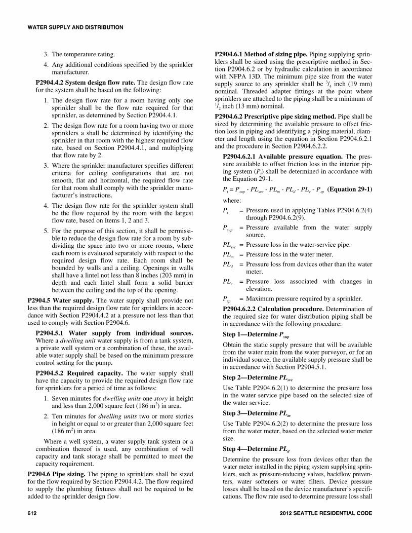
3. The temperature rating.
4. Any additional conditions specified by the sprinklermanufacturer.
P2904.4.2 System design flow rate. The design flow ratefor the system shall be based on the following:
1. The design flow rate for a room having only onesprinkler shall be the flow rate required for thatsprinkler, as determined by Section P2904.4.1.
2. The design flow rate for a room having two or moresprinklers a shall be determined by identifying thesprinkler in that room with the highest required flowrate, based on Section P2904.4.1, and multiplyingthat flow rate by 2.
3. Where the sprinkler manufacturer specifies differentcriteria for ceiling configurations that are notsmooth, flat and horizontal, the required flow ratefor that room shall comply with the sprinkler manu-facturer’s instructions.
4. The design flow rate for the sprinkler system shallbe the flow required by the room with the largestflow rate, based on Items 1, 2 and 3.
5. For the purpose of this section, it shall be permissi-ble to reduce the design flow rate for a room by sub-dividing the space into two or more rooms, whereeach room is evaluated separately with respect to therequired design flow rate. Each room shall bebounded by walls and a ceiling. Openings in wallsshall have a lintel not less than 8 inches (203 mm) indepth and each lintel shall form a solid barrierbetween the ceiling and the top of the opening.
P2904.5 Water supply. The water supply shall provide notless than the required design flow rate for sprinklers in accor-dance with Section P2904.4.2 at a pressure not less than thatused to comply with Section P2904.6.
P2904.5.1 Water supply from individual sources.Where a dwelling unit water supply is from a tank system,a private well system or a combination of these, the avail-able water supply shall be based on the minimum pressurecontrol setting for the pump.
P2904.5.2 Required capacity. The water supply shallhave the capacity to provide the required design flow ratefor sprinklers for a period of time as follows:
1. Seven minutes for dwelling units one story in heightand less than 2,000 square feet (186 m2) in area.
2. Ten minutes for dwelling units two or more storiesin height or equal to or greater than 2,000 square feet(186 m2) in area.
Where a well system, a water supply tank system or acombination thereof is used, any combination of wellcapacity and tank storage shall be permitted to meet thecapacity requirement.
P2904.6 Pipe sizing. The piping to sprinklers shall be sizedfor the flow required by Section P2904.4.2. The flow requiredto supply the plumbing fixtures shall not be required to beadded to the sprinkler design flow.
P2904.6.1 Method of sizing pipe. Piping supplying sprin-klers shall be sized using the prescriptive method in Sec-tion P2904.6.2 or by hydraulic calculation in accordancewith NFPA 13D. The minimum pipe size from the watersupply source to any sprinkler shall be 3/4 inch (19 mm)nominal. Threaded adapter fittings at the point wheresprinklers are attached to the piping shall be a minimum of1/2 inch (13 mm) nominal.
P2904.6.2 Prescriptive pipe sizing method. Pipe shall besized by determining the available pressure to offset fric-tion loss in piping and identifying a piping material, diam-eter and length using the equation in Section P2904.6.2.1and the procedure in Section P2904.6.2.2.
P2904.6.2.1 Available pressure equation. The pres-sure available to offset friction loss in the interior pip-ing system (Pt) shall be determined in accordance withthe Equation 29-1.
Pt = Psup - PLsvc - PLm - PLd - PLe - Psp (Equation 29-1)
where:
Pt = Pressure used in applying Tables P2904.6.2(4)through P2904.6.2(9).
Psup = Pressure available from the water supplysource.
PLsvc = Pressure loss in the water-service pipe.
PLm = Pressure loss in the water meter.
PLd = Pressure loss from devices other than the watermeter.
PLe = Pressure loss associated with changes inelevation.
Psp = Maximum pressure required by a sprinkler.
P2904.6.2.2 Calculation procedure. Determination ofthe required size for water distribution piping shall bein accordance with the following procedure:
Step 1—Determine Psup
Obtain the static supply pressure that will be availablefrom the water main from the water purveyor, or for anindividual source, the available supply pressure shall bein accordance with Section P2904.5.1.
Step 2—Determine PLsvc
Use Table P2904.6.2(1) to determine the pressure lossin the water service pipe based on the selected size ofthe water service.
Step 3—Determine PLm
Use Table P2904.6.2(2) to determine the pressure lossfrom the water meter, based on the selected water metersize.
Step 4—Determine PLd
Determine the pressure loss from devices other than thewater meter installed in the piping system supplying sprin-klers, such as pressure-reducing valves, backflow preven-ters, water softeners or water filters. Device pressurelosses shall be based on the device manufacturer’s specifi-cations. The flow rate used to determine pressure loss shall
29_Seattle_Res_2012.fm Page 612 Monday, September 9, 2013 12:37 PM

WATER SUPPLY AND DISTRIBUTION
2012 SEATTLE RESIDENTIAL CODE 613
be the rate from Section P2904.4.2, except that 5 gpm (0.3L/s) shall be added where the device is installed in awater-service pipe that supplies more than one dwelling.As an alternative to deducting pressure loss for a device,an automatic bypass valve shall be installed to divert flowaround the device when a sprinkler activates.
Step 5—Determine PLe
Use Table P2904.6.2(3) to determine the pressure lossassociated with changes in elevation. The elevationused in applying the table shall be the differencebetween the elevation where the water source pressurewas measured and the elevation of the highest sprin-kler.
Step 6—Determine Psp
Determine the maximum pressure required by any indi-vidual sprinkler based on the flow rate from SectionP2904.4.1. The required pressure is provided in thesprinkler manufacturer’s published data for the specificsprinkler model based on the selected flow rate.
Step 7—Calculate Pt
Using Equation 29-1, calculate the pressure available tooffset friction loss in water-distribution piping betweenthe service valve and the sprinklers.
Step 8—Determine the maximum allowable pipelength
Use Tables P2904.6.2(4) through P2904.6.2(9) to selecta material and size for water distribution piping. Thepiping material and size shall be acceptable if the devel-oped length of pipe between the service valve and themost remote sprinkler does not exceed the maximumallowable length specified by the applicable table.Interpolation of Pt between the tabular values shall bepermitted.
The maximum allowable length of piping in TablesP2904.6.2(4) through P2904.6.2(9) incorporates anadjustment for pipe fittings, and no additional consider-ation of friction losses associated with pipe fittingsshall be required.
P2904.7 Instructions and signs. An owner’s manual for thefire sprinkler system shall be provided to the owner. A sign orvalve tag shall be installed at the main shutoff valve to thewater distribution system stating the following: “Warning,the water system for this home supplies fire sprinklers thatrequire certain flows and pressures to fight a fire. Devicesthat restrict the flow or decrease the pressure or automaticallyshut off the water to the fire sprinkler system, such as watersofteners, filtration systems and automatic shutoff valves,shall not be added to this system without a review of the firesprinkler system by a fire protection specialist. Do notremove this sign.”
TABLE P2904.6.2(1)WATER SERVICE PRESSURE LOSS (PLsvc)
a, b
For SI: 1 inch = 25.4 mm, 1 foot = 304.8 mm, 1 gallon per minute = 0.063 L/s, 1 pound per square inch = 6.895 kPa.NP = Not permitted. Pressure loss exceeds reasonable limits.a. Values are applicable for underground piping materials listed in Table P2905.4 and are based on an SDR of 11 and a Hazen Williams C Factor of 150.b. Values include the following length allowances for fittings: 25% length increase for actual lengths up to 100 feet and 15% length increase for actual lengths
over 100 feet.c. Flow rate from Section P2904.4.2. Add 5 gpm to the flow rate required by Section P2904.4.2 where the water-service pipe supplies more than one dwelling.
FLOW RATEc (gpm)
3/4-INCH WATER SERVICE PRESSURE LOSS (psi)
1-INCH WATER SERVICE PRESSURE LOSS (psi)
11/4 -INCH WATER SERVICE PRESSURE LOSS (psi)
Length of water service pipe (feet) Length of water service pipe (feet) Length of water service pipe (feet)
40 or less 41 to 75 76 to 100 101 to 150 40 or
less 41 to 75 76 to 100 101 to 150 40 or less 41 to 75 76 to 100 101 to 150
8 5.1 8.7 11.8 17.4 1.5 2.5 3.4 5.1 0.6 1.0 1.3 1.9
10 7.7 13.1 17.8 26.3 2.3 3.8 5.2 7.7 0.8 1.4 2.0 2.9
12 10.8 18.4 24.9 NP 3.2 5.4 7.3 10.7 1.2 2.0 2.7 4.0
14 14.4 24.5 NP NP 4.2 7.1 9.6 14.3 1.6 2.7 3.6 5.4
16 18.4 NP NP NP 5.4 9.1 12.4 18.3 2.0 3.4 4.7 6.9
18 22.9 NP NP NP 6.7 11.4 15.4 22.7 2.5 4.3 5.8 8.6
20 27.8 NP NP NP 8.1 13.8 18.7 27.6 3.1 5.2 7.0 10.4
22 NP NP NP NP 9.7 16.5 22.3 NP 3.7 6.2 8.4 12.4
24 NP NP NP NP 11.4 19.3 26.2 NP 4.3 7.3 9.9 14.6
26 NP NP NP NP 13.2 22.4 NP NP 5.0 8.5 11.4 16.9
28 NP NP NP NP 15.1 25.7 NP NP 5.7 9.7 13.1 19.4
30 NP NP NP NP 17.2 NP NP NP 6.5 11.0 14.9 22.0
32 NP NP NP NP 19.4 NP NP NP 7.3 12.4 16.8 24.8
34 NP NP NP NP 21.7 NP NP NP 8.2 13.9 18.8 NP
36 NP NP NP NP 24.1 NP NP NP 9.1 15.4 20.9 NP
29_Seattle_Res_2012.fm Page 613 Monday, September 9, 2013 12:37 PM

WATER SUPPLY AND DISTRIBUTION
614 2012 SEATTLE RESIDENTIAL CODE
TABLE P2904.6.2(2)MINIMUM WATER METER PRESSURE LOSS (PLm)a
For SI: 1 inch = 25.4 mm, 1 pound per square inch = 6.895 kPa, 1 gallon per minute = 0.063 L/s.NP—Not permitted unless the actual water meter pressure loss is known.a. Table P2904.6.2(2) establishes conservative values for water meter pressure loss or installations where the water meter loss is unknown. Where the actual
water meter pressure loss is known, Pm shall be the actual loss.b. Flow rate from Section P2904.4.2. Add 5 gpm to the flow rate required by Section P2904.4.2 where the water-service pipe supplies more than one dwelling.
FLOW RATE (gallons per minute, gpm)b
5/8-INCH METER PRESSURE LOSS(pounds per square inch, psi)
3/4-INCH METER PRESSURE LESS (pounds per square inch, psi)
1-INCH METER PRESSURE LOSS (pounds per square inch, psi)
8 2 1 1
10 3 1 1
12 4 1 1
14 5 2 1
16 7 3 1
18 9 4 1
20 11 4 2
22 NP 5 2
24 NP 5 2
26 NP 6 2
28 NP 6 2
30 NP 7 2
32 NP 7 3
34 NP 8 3
36 NP 8 3
TABLE P2904.6.2(3)ELEVATION LOSS (PLe)
For SI: 1 foot = 304.8 mm, 1 pound per square inch = 6.895 kPa.
ELEVATION (feet) PRESSURE LOSS (psi)
5 2.2
10 4.4
15 6.5
20 8.7
25 10.9
30 13
35 15.2
40 17.4
29_Seattle_Res_2012.fm Page 614 Monday, September 9, 2013 12:37 PM

WATER SUPPLY AND DISTRIBUTION
2012 SEATTLE RESIDENTIAL CODE 615
TABLE P2904.6.2(4)ALLOWABLE PIPE LENGTH FOR 3/4-INCH TYPE M COPPER WATER TUBING
For SI: 1 inch = 25.4 mm, 1 foot = 304.8 mm, 1 pound per square inch = 6.895 kPa, 1 gallon per minute = 0.963 L/s.NP—Not permitted.a. Flow rate from Section P2904.4.2.
SPRINKLER FLOW RATEa
(gpm)
WATER DISTRIBUTION
SIZE (inch)
AVAILABLE PRESSURE—Pt (psi)
15 20 25 30 35 40 45 50 55 60
Allowable length of pipe from service valve to farthest sprinkler (feet)
8 3/4 217 289 361 434 506 578 650 723 795 867
9 3/4 174 232 291 349 407 465 523 581 639 697
10 3/4 143 191 239 287 335 383 430 478 526 574
11 3/4 120 160 200 241 281 321 361 401 441 481
12 3/4 102 137 171 205 239 273 307 341 375 410
13 3/4 88 118 147 177 206 235 265 294 324 353
14 3/4 77 103 128 154 180 205 231 257 282 308
15 3/4 68 90 113 136 158 181 203 226 248 271
16 3/4 60 80 100 120 140 160 180 200 220 241
17 3/4 54 72 90 108 125 143 161 179 197 215
18 3/4 48 64 81 97 113 129 145 161 177 193
19 3/4 44 58 73 88 102 117 131 146 160 175
20 3/4 40 53 66 80 93 106 119 133 146 159
21 3/4 36 48 61 73 85 97 109 121 133 145
22 3/4 33 44 56 67 78 89 100 111 122 133
23 3/4 31 41 51 61 72 82 92 102 113 123
24 3/4 28 38 47 57 66 76 85 95 104 114
25 3/4 26 35 44 53 61 70 79 88 97 105
26 3/4 24 33 41 49 57 65 73 82 90 98
27 3/4 23 30 38 46 53 61 69 76 84 91
28 3/4 21 28 36 43 50 57 64 71 78 85
29 3/4 20 27 33 40 47 53 60 67 73 80
30 3/4 19 25 31 38 44 50 56 63 69 75
31 3/4 18 24 29 35 41 47 53 59 65 71
32 3/4 17 22 28 33 39 44 50 56 61 67
33 3/4 16 21 26 32 37 42 47 53 58 63
34 3/4 NP 20 25 30 35 40 45 50 55 60
35 3/4 NP 19 24 28 33 38 42 47 52 57
36 3/4 NP 18 22 27 31 36 40 45 49 54
37 3/4 NP 17 21 26 30 34 38 43 47 51
38 3/4 NP 16 20 24 28 32 36 40 45 49
39 3/4 NP 15 19 23 27 31 35 39 42 46
40 3/4 NP NP 18 22 26 29 33 37 40 44
29_Seattle_Res_2012.fm Page 615 Monday, September 9, 2013 12:37 PM

WATER SUPPLY AND DISTRIBUTION
616 2012 SEATTLE RESIDENTIAL CODE
TABLE P2904.6.2(5)ALLOWABLE PIPE LENGTH FOR 1-INCH TYPE M COPPER WATER TUBING
For SI: 1 inch = 25.4 mm, 1 foot = 304.8 mm, 1 pound per square inch = 6.895 kPa, 1 gallon per minute = 0.963 L/s.a. Flow rate from Section P2904.4.2.
SPRINKLER FLOW RATEa
(gpm)
WATER DISTRIBUTION
SIZE (inch)
AVAILABLE PRESSURE—Pt (psi)
15 20 25 30 35 40 45 50 55 60
Allowable length of pipe from service valve to farthest sprinkler (feet)
8 1 806 1075 1343 1612 1881 2149 2418 2687 2955 3224
9 1 648 864 1080 1296 1512 1728 1945 2161 2377 2593
10 1 533 711 889 1067 1245 1422 1600 1778 1956 2134
11 1 447 586 745 894 1043 1192 1341 1491 1640 1789
12 1 381 508 634 761 888 1015 1142 1269 1396 1523
13 1 328 438 547 657 766 875 985 1094 1204 1313
14 1 286 382 477 572 668 763 859 954 1049 1145
15 1 252 336 420 504 588 672 756 840 924 1008
16 1 224 298 373 447 522 596 671 745 820 894
17 1 200 266 333 400 466 533 600 666 733 799
18 1 180 240 300 360 420 479 539 599 659 719
19 1 163 217 271 325 380 434 488 542 597 651
20 1 148 197 247 296 345 395 444 493 543 592
21 1 135 180 225 270 315 360 406 451 496 541
22 1 124 165 207 248 289 331 372 413 455 496
23 1 114 152 190 228 267 305 343 381 419 457
24 1 106 141 176 211 246 282 317 352 387 422
25 1 98 131 163 196 228 261 294 326 359 392
26 1 91 121 152 182 212 243 273 304 334 364
27 1 85 113 142 170 198 226 255 283 311 340
28 1 79 106 132 159 185 212 238 265 291 318
29 1 74 99 124 149 174 198 223 248 273 298
30 1 70 93 116 140 163 186 210 233 256 280
31 1 66 88 110 132 153 175 197 219 241 263
32 1 62 83 103 124 145 165 186 207 227 248
33 1 59 78 98 117 137 156 176 195 215 234
34 1 55 74 92 111 129 148 166 185 203 222
35 1 53 70 88 105 123 140 158 175 193 210
36 1 50 66 83 100 116 133 150 166 183 199
37 1 47 63 79 95 111 126 142 158 174 190
38 1 45 60 75 90 105 120 135 150 165 181
39 1 43 57 72 86 100 115 129 143 158 172
40 1 41 55 68 82 96 109 123 137 150 164
29_Seattle_Res_2012.fm Page 616 Monday, September 9, 2013 12:37 PM

WATER SUPPLY AND DISTRIBUTION
2012 SEATTLE RESIDENTIAL CODE 617
TABLE P2904.6.2(6)ALLOWABLE PIPE LENGTH FOR 3/4-INCH CPVC PIPE
For SI: 1 inch = 25.4 mm, 1 foot = 304.8 mm, 1 pound per square inch = 6.895 kPa, 1 gallon per minute = 0.963 L/s.a. Flow rate from Section P2904.4.2.
SPRINKLER FLOW RATEa
(gpm)
WATER DISTRIBUTION
SIZE (inch)
AVAILABLE PRESSURE—Pt (psi)
15 20 25 30 35 40 45 50 55 60
Allowable length of pipe from service valve to farthest sprinkler (feet)
8 3/4 348 465 581 697 813 929 1045 1161 1278 1394
9 3/4 280 374 467 560 654 747 841 934 1027 1121
10 3/4 231 307 384 461 538 615 692 769 845 922
11 3/4 193 258 322 387 451 515 580 644 709 773
12 3/4 165 219 274 329 384 439 494 549 603 658
13 3/4 142 189 237 284 331 378 426 473 520 568
14 3/4 124 165 206 247 289 330 371 412 454 495
15 3/4 109 145 182 218 254 290 327 363 399 436
16 3/4 97 129 161 193 226 258 290 322 354 387
17 3/4 86 115 144 173 202 230 259 288 317 346
18 3/4 78 104 130 155 181 207 233 259 285 311
19 3/4 70 94 117 141 164 188 211 234 258 281
20 3/4 64 85 107 128 149 171 192 213 235 256
21 3/4 58 78 97 117 136 156 175 195 214 234
22 3/4 54 71 89 107 125 143 161 179 197 214
23 3/4 49 66 82 99 115 132 148 165 181 198
24 3/4 46 61 76 91 107 122 137 152 167 183
25 3/4 42 56 71 85 99 113 127 141 155 169
26 3/4 39 52 66 79 92 105 118 131 144 157
27 3/4 37 49 61 73 86 98 110 122 135 147
28 3/4 34 46 57 69 80 92 103 114 126 137
29 3/4 32 43 54 64 75 86 96 107 118 129
30 3/4 30 40 50 60 70 81 91 101 111 121
31 3/4 28 38 47 57 66 76 85 95 104 114
32 3/4 27 36 45 54 63 71 80 89 98 107
33 3/4 25 34 42 51 59 68 76 84 93 101
34 3/4 24 32 40 48 56 64 72 80 88 96
35 3/4 23 30 38 45 53 61 68 76 83 91
36 3/4 22 29 36 43 50 57 65 72 79 86
37 3/4 20 27 34 41 48 55 61 68 75 82
38 3/4 20 26 33 39 46 52 59 65 72 78
39 3/4 19 25 31 37 43 50 56 62 68 74
40 3/4 18 24 30 35 41 47 53 59 65 71
29_Seattle_Res_2012.fm Page 617 Monday, September 9, 2013 12:37 PM

WATER SUPPLY AND DISTRIBUTION
618 2012 SEATTLE RESIDENTIAL CODE
TABLE P2904.6.2(7)ALLOWABLE PIPE LENGTH FOR 1-INCH CPVC PIPE
For SI: 1 inch = 25.4 mm, 1 foot = 304.8 mm, 1 pound per square inch = 6.895 kPa, 1 gallon per minute = 0.963 L/s.a. Flow rate from Section P2904.4.2.
SPRINKLER FLOW RATEa
(gpm)
WATER DISTRIBUTION
SIZE (inch)
AVAILABLE PRESSURE—Pt (psi)
15 20 25 30 35 40 45 50 55 60
Allowable length of pipe from service valve to farthest sprinkler (feet)
8 1 1049 1398 1748 2098 2447 2797 3146 3496 3845 4195
9 1 843 1125 1406 1687 1968 2249 2530 2811 3093 3374
10 1 694 925 1157 1388 1619 1851 2082 2314 2545 2776
11 1 582 776 970 1164 1358 1552 1746 1940 2133 2327
12 1 495 660 826 991 1156 1321 1486 1651 1816 1981
13 1 427 570 712 854 997 1139 1281 1424 1566 1709
14 1 372 497 621 745 869 993 1117 1241 1366 1490
15 1 328 437 546 656 765 874 983 1093 1202 1311
16 1 291 388 485 582 679 776 873 970 1067 1164
17 1 260 347 433 520 607 693 780 867 954 1040
18 1 234 312 390 468 546 624 702 780 858 936
19 1 212 282 353 423 494 565 635 706 776 847
20 1 193 257 321 385 449 513 578 642 706 770
21 1 176 235 293 352 410 469 528 586 645 704
22 1 161 215 269 323 377 430 484 538 592 646
23 1 149 198 248 297 347 396 446 496 545 595
24 1 137 183 229 275 321 366 412 458 504 550
25 1 127 170 212 255 297 340 382 425 467 510
26 1 118 158 197 237 276 316 355 395 434 474
27 1 111 147 184 221 258 295 332 368 405 442
28 1 103 138 172 207 241 275 310 344 379 413
29 1 97 129 161 194 226 258 290 323 355 387
30 1 91 121 152 182 212 242 273 303 333 364
31 1 86 114 143 171 200 228 257 285 314 342
32 1 81 108 134 161 188 215 242 269 296 323
33 1 76 102 127 152 178 203 229 254 280 305
34 1 72 96 120 144 168 192 216 240 265 289
35 1 68 91 114 137 160 182 205 228 251 273
36 1 65 87 108 130 151 173 195 216 238 260
37 1 62 82 103 123 144 165 185 206 226 247
38 1 59 78 98 117 137 157 176 196 215 235
39 1 56 75 93 112 131 149 168 187 205 224
40 1 53 71 89 107 125 142 160 178 196 214
29_Seattle_Res_2012.fm Page 618 Monday, September 9, 2013 12:37 PM

WATER SUPPLY AND DISTRIBUTION
2012 SEATTLE RESIDENTIAL CODE 619
TABLE P2904.6.2(8)ALLOWABLE PIPE LENGTH FOR 3/4-INCH PEX AND PE-RT TUBING
For SI: 1 inch = 25.4 mm, 1 foot = 304.8 mm, 1 pound per square inch = 6.895 kPa, 1 gallon per minute = 0.963 L/s.NP—Not permitted.a. Flow rate from Section P2904.4.2.
SPRINKLER FLOW RATEa
(gpm)
WATER DISTRIBUTION
SIZE (inch)
AVAILABLE PRESSURE—Pt (psi)
15 20 25 30 35 40 45 50 55 60
Allowable length of pipe from service valve to farthest sprinkler (feet)
8 3/4 93 123 154 185 216 247 278 309 339 370
9 3/4 74 99 124 149 174 199 223 248 273 298
10 3/4 61 82 102 123 143 163 184 204 225 245
11 3/4 51 68 86 103 120 137 154 171 188 205
12 3/4 44 58 73 87 102 117 131 146 160 175
13 3/4 38 50 63 75 88 101 113 126 138 151
14 3/4 33 44 55 66 77 88 99 110 121 132
15 3/4 29 39 48 58 68 77 87 96 106 116
16 3/4 26 34 43 51 60 68 77 86 94 103
17 3/4 23 31 38 46 54 61 69 77 84 92
18 3/4 21 28 34 41 48 55 62 69 76 83
19 3/4 19 25 31 37 44 50 56 62 69 75
20 3/4 17 23 28 34 40 45 51 57 62 68
21 3/4 16 21 26 31 36 41 47 52 57 62
22 3/4 NP 19 24 28 33 38 43 47 52 57
23 3/4 NP 17 22 26 31 35 39 44 48 52
24 3/4 NP 16 20 24 28 32 36 40 44 49
25 3/4 NP NP 19 22 26 30 34 37 41 45
26 3/4 NP NP 17 21 24 28 31 35 38 42
27 3/4 NP NP 16 20 23 26 29 33 36 39
28 3/4 NP NP 15 18 21 24 27 30 33 36
29 3/4 NP NP NP 17 20 23 26 28 31 34
30 3/4 NP NP NP 16 19 21 24 27 29 32
31 3/4 NP NP NP 15 18 20 23 25 28 30
32 3/4 NP NP NP NP 17 19 21 24 26 28
33 3/4 NP NP NP NP 16 18 20 22 25 27
34 3/4 NP NP NP NP NP 17 19 21 23 25
35 3/4 NP NP NP NP NP 16 18 20 22 24
36 3/4 NP NP NP NP NP 15 17 19 21 23
37 3/4 NP NP NP NP NP NP 16 18 20 22
38 3/4 NP NP NP NP NP NP 16 17 19 21
39 3/4 NP NP NP NP NP NP NP 16 18 20
40 3/4 NP NP NP NP NP NP NP 16 17 19
29_Seattle_Res_2012.fm Page 619 Monday, September 9, 2013 12:37 PM

WATER SUPPLY AND DISTRIBUTION
620 2012 SEATTLE RESIDENTIAL CODE
TABLE P2904.6.2(9)ALLOWABLE PIPE LENGTH FOR 1-INCH PEX AND PE-RT TUBING
For SI: 1 inch = 25.4 mm, 1 foot = 304.8 mm, 1 pound per square inch = 6.895 kPa, 1 gallon per minute = 0.963 L/s.a. Flow rate from Section P2904.4.2.
SPRINKLER FLOW RATEa
(gpm)
WATER DISTRIBUTION
SIZE (inch)
AVAILABLE PRESSURE—Pt (psi)
15 20 25 30 35 40 45 50 55 60
Allowable length of pipe from service valve to farthest sprinkler (feet)
8 1 314 418 523 628 732 837 941 1046 1151 1255
9 1 252 336 421 505 589 673 757 841 925 1009
10 1 208 277 346 415 485 554 623 692 761 831
11 1 174 232 290 348 406 464 522 580 638 696
12 1 148 198 247 296 346 395 445 494 543 593
13 1 128 170 213 256 298 341 383 426 469 511
14 1 111 149 186 223 260 297 334 371 409 446
15 1 98 131 163 196 229 262 294 327 360 392
16 1 87 116 145 174 203 232 261 290 319 348
17 1 78 104 130 156 182 208 233 259 285 311
18 1 70 93 117 140 163 187 210 233 257 280
19 1 63 84 106 127 148 169 190 211 232 253
20 1 58 77 96 115 134 154 173 192 211 230
21 1 53 70 88 105 123 140 158 175 193 211
22 1 48 64 80 97 113 129 145 161 177 193
23 1 44 59 74 89 104 119 133 148 163 178
24 1 41 55 69 82 96 110 123 137 151 164
25 1 38 51 64 76 89 102 114 127 140 152
26 1 35 47 59 71 83 95 106 118 130 142
27 1 33 44 55 66 77 88 99 110 121 132
28 1 31 41 52 62 72 82 93 103 113 124
29 1 29 39 48 58 68 77 87 97 106 116
30 1 27 36 45 54 63 73 82 91 100 109
31 1 26 34 43 51 60 68 77 85 94 102
32 1 24 32 40 48 56 64 72 80 89 97
33 1 23 30 38 46 53 61 68 76 84 91
34 1 22 29 36 43 50 58 65 72 79 86
35 1 20 27 34 41 48 55 61 68 75 82
36 1 19 26 32 39 45 52 58 65 71 78
37 1 18 25 31 37 43 49 55 62 68 74
38 1 18 23 29 35 41 47 53 59 64 70
39 1 17 22 28 33 39 45 50 56 61 67
40 1 16 21 27 32 37 43 48 53 59 64
29_Seattle_Res_2012.fm Page 620 Monday, September 9, 2013 12:37 PM

WATER SUPPLY AND DISTRIBUTION
2012 SEATTLE RESIDENTIAL CODE 621
P2904.8 Inspections. The water distribution system shall beinspected in accordance with Sections P2904.8.1 andP2904.8.2.
P2904.8.1 Preconcealment inspection. The followingitems shall be verified prior to the concealment of anysprinkler system piping:
1. Sprinklers are installed in all areas as required bySection P2904.1.1.
2. Where sprinkler water spray patterns are obstructedby construction features, luminaires or ceiling fans,additional sprinklers are installed as required bySection P2904.2.4.2.
3. Sprinklers are the correct temperature rating and areinstalled at or beyond the required separation dis-tances from heat sources as required by SectionsP2904.2.1 and P2904.2.2.
4. The pipe size equals or exceeds the size used inapplying Tables P2904.6.2(4) through P2904.6.2(9)or, if the piping system was hydraulically calculatedin accordance with Section P2904.6.1, the size usedin the hydraulic calculation.
5. The pipe length does not exceed the length permit-ted by Tables P2904.6.2(4) through P2904.6.2(9) or,if the piping system was hydraulically calculated inaccordance with Section P2904.6.1, pipe lengths andfittings do not exceed those used in the hydrauliccalculation.
6. Nonmetallic piping that conveys water to sprinklersis listed for use with fire sprinklers.
7. Piping is supported in accordance with the pipemanufacturer’s and sprinkler manufacturer’s instal-lation instructions.
8. The piping system is tested in accordance with Sec-tion P2503.7.
P2904.8.2 Final inspection. The following items shall beverified upon completion of the system:
1. Sprinkler are not painted, damaged or otherwise hin-dered from operation.
2. Where a pump is required to provide water to thesystem, the pump starts automatically upon systemwater demand.
3. Pressure-reducing valves, water softeners, water fil-ters or other impairments to water flow that were notpart of the original design have not been installed.
4. The sign or valve tag required by Section P2904.7 isinstalled and the owner’s manual for the system ispresent.
((SECTION P2905MATERIALS, JOINTS AND CONNECTIONS
P2905.1 Soil and groundwater. The installation of waterservice pipe, water distribution pipe, fittings, valves, appurte-nances and gaskets shall be prohibited in soil and groundwa-ter that is contaminated with solvents, fuels, organic
compounds or other detrimental materials that cause perme-ation, corrosion, degradation or structural failure of the waterservice or water distribution piping material.
P2905.1.1 Investigation required. Where detrimentalconditions are suspected by or brought to the attention ofthe building official, a chemical analysis of the soil andgroundwater conditions shall be required to ascertain theacceptability of the water service material for the specificinstallation.
P2905.1.2 Detrimental condition. When a detrimentalcondition exists, approved alternate materials or alternaterouting shall be required.
P2905.2 Lead content. Pipe and fittings used in the water-supply system shall have lead content of not greater than 8percent lead.
P2905.3 Polyethylene plastic piping installation. Polyeth-ylene pipe shall be cut square using a cutter designed for plas-tic pipe. Except where joined by heat fusion, pipe ends shallbe chamfered to remove sharp edges. Pipe that has beenkinked shall not be installed. For bends, the installed radius ofpipe curvature shall be greater than 30 pipe diameters or thecoil radius when bending with the coil. Coiled pipe shall notbe bent beyond straight. Bends shall not be permitted within10 pipe diameters of any fitting or valve. Joints between poly-ethylene plastic pipe and fittings shall comply with SectionsP2905.3.1 and P2905.3.2.
P2905.3.1 Heat-fusion joints. Joint surfaces shall beclean and free from moisture. Joint surfaces shall beheated to melting temperature and joined. The joint shallbe undisturbed until cool. Joints shall be made in accor-dance with ASTM D 2657.
P2905.3.2 Mechanical joints. Mechanical joints shall beinstalled in accordance with the manufacturer’s instruc-tions.
P2905.4 Water service pipe. Water service pipe shall con-form to NSF 61 and shall conform to one of the standardslisted in Table P2905.4. Water service pipe or tubing,installed underground and outside of the structure, shall havea working pressure rating of not less than 160 pounds persquare inch at 73°F (1103 kPa at 23°C). Where the waterpressure exceeds 160 pounds per square inch (1103 kPa), pip-ing material shall have a rated working pressure equal to orgreater than the highest available pressure. Water service pip-ing materials not third-party certified for water distributionshall terminate at or before the full open valve located at theentrance to the structure. Ductile iron water service pipingshall be cement mortar lined in accordance with AWWAC104.
P2905.4.1 Dual check-valve-type backflow preventer.Where a dual check-valve backflow preventer is installedon the water supply system, it shall comply with ASSE1024 or CSA B64.6.
P2905.4.2 Water service installation. Trenching, pipeinstallation and backfilling shall be in accordance withSection P2604. Water-service pipe is permitted to belocated in the same trench with a building sewer providedsuch sewer is constructed of materials listed for under-
29_Seattle_Res_2012.fm Page 621 Monday, September 9, 2013 12:37 PM

WATER SUPPLY AND DISTRIBUTION
622 2012 SEATTLE RESIDENTIAL CODE
ground use within a building in Section P3002.1. If thebuilding sewer is not constructed of materials listed inSection P3002.1, the water-service pipe shall be separatedfrom the building sewer by not less than 5 feet (1524 mm),measured horizontally, of undisturbed or compacted earthor placed on a solid ledge not less than 12 inches (305mm) above and to one side of the highest point in thesewer line.
Exception: The required separation distance shall notapply where a water service pipe crosses a sewer pipe,provided that the water service pipe is sleeved not lessthan 5 feet (1524 mm), horizontally from the sewerpipe centerline, on both sides of the crossing with pipematerials listed in Table P2905.4, P3002.1(1),P3002.1(2) or P3002.2.
P2905.5 Water-distribution pipe. Water-distribution pip-ing within dwelling units shall conform to NSF 61 and shallconform to one of the standards listed in Table P2905.5. Allhot-water-distribution pipe and tubing shall have a pressurerating of not less than 100 psi at 180°F (689 kPa at 82°C).
P2905.6 Fittings. Pipe fittings shall be approved for installa-tion with the piping material installed and shall comply withthe applicable standards listed in Table P2905.6. All pipe fit-tings used in water supply systems shall also comply withNSF 61.
P2905.7 Flexible water connectors. Flexible water connec-tors, exposed to continuous pressure, shall conform to ASMEA112.18.6/CSA B125.6. Access shall be provided to all flex-ible water connectors.
P2905.8 Joint and connection tightness. Joints and connec-tions in the plumbing system shall be gas tight and water tightfor the intended use or required test pressure.
P2905.9 Plastic pipe joints. Joints in plastic piping shall bemade with approved fittings by solvent cementing, heatfusion, corrosion-resistant metal clamps with insert fittings orcompression connections. Flared joints for polyethylene pipeshall be permitted in accordance with Section P2905.3.
P2905.9.1 Solvent cementing. Solvent-cemented jointsshall comply with Sections P2905.9.1.1 throughP2905.9.1.3.
P2905.9.1.1 ABS plastic pipe. Solvent cement forABS plastic pipe conforming to ASTM D 2235 shall beapplied to all joint surfaces.
P2905.9.1.2 CPVC plastic pipe. Joint surfaces shall beclean and free from moisture and an approved primershall be applied. Solvent cement for CPVC plastic pipe,orange in color and conforming to ASTM F 493, shallbe applied to all joint surfaces. The parts shall be joinedwhile the cement is wet and in accordance with ASTMD 2846 or ASTM F 493. Solvent-cement joints shall bepermitted above or below ground.
Exception: A primer shall not be required where allof the following conditions apply:
1. The solvent cement used is third-party certi-fied as conforming to ASTM F 493.
2. The solvent cement used is yellow in color.
TABLE P2905.4WATER SERVICE PIPE
MATERIAL STANDARD
Acrylonitrile butadiene styrene (ABS) plastic pipe ASTM D 1527; ASTM D 2282
Asbestos-cement pipe ASTM C 296
Brass pipe ASTM B 43
Chlorinated polyvinyl chloride (CPVC) plastic pipe ASTM D 2846; ASTM F 441; ASTM F 442; CSA B137.6
Copper or copper-alloy pipe ASTM B 42; ASTM B 302
Copper or copper-alloy tubing (Type K, WK, L, WL, M or WM) ASTM B 75; ASTM B 88; ASTM B 251; ASTM B 447
Cross-linked polyethylene/aluminum/cross-linked polyethylene (PEX-AL-PEX) pipe
ASTM F 1281; ASTM F 2262; CSA B137.10M
Cross-linked polyethylene/aluminum/high-density polyethylene (PEX-AL-HDPE)
ASTM F 1986
Cross-linked polyethylene (PEX) plastic tubing ASTM F 876; ASTM F 877; CSA B137.5
Ductile iron water pipe AWWA C151; AWWA C115
Galvanized steel pipe ASTM A 53
Polyethylene/aluminum/polyethylene (PE-AL-PE) pipe ASTM F 1282; CSA CAN/CSA-B137.9M
Polyethylene (PE) plastic pipe ASTM D 2104; ASTM D 2239; AWWA C901; CSA B137.1
Polyethylene (PE) plastic tubing ASTM D 2737; AWWA C901; CSA B137.1
Polyethylene of raised temperature (PE-RT) plastic tubing ASTM F 2769
Polyvinyl chloride (PVC) plastic pipe ASTM D 1785; ASTM D 2241; ASTM D 2672; CSA B137.3
Stainless steel (Type 304/304L) pipe ASTM A 312; ASTM A 778
Stainless steel (Type 316/316L) pipe ASTM A 312; ASTM A 778
29_Seattle_Res_2012.fm Page 622 Monday, September 9, 2013 12:37 PM

WATER SUPPLY AND DISTRIBUTION
2012 SEATTLE RESIDENTIAL CODE 623
3. The solvent cement is used only for joining 1/2
inch (13 mm) through 2 inch (51 mm) diameterCPVC pipe and fittings.
4. The CPVC pipe and fittings are manufacturedin accordance with ASTM D 2846.
P2905.9.1.3 PVC plastic pipe. A purple primer thatconforms to ASTM F 656 shall be applied to PVC sol-vent-cemented joints. Solvent cement for PVC plasticpipe conforming to ASTM D 2564 shall be applied toall joint surfaces.
TABLE P2905.6PIPE FITTINGS
MATERIAL STANDARD
Acrylonitrile butadiene styrene (ABS) plastic ASTM D 2468
Brass ASTM F1974
Cast-iron ASME B16.4; ASME B16.12
Chlorinated polyvinyl chloride (CPVC) plastic ASSE 1061; ASTM D 2846; ASTM F 437; ASTM F 438; ASTM F 439; CSA B137.6
Copper or copper alloy ASSE 1061; ASME B16.15; ASME B16.18; ASME B16.22; ASME B16.23; ASME B16.26; ASME B16.29
Cross-linked polyethylene/aluminum/high-density polyethylene (PEX-AL-HDPE)
ASTM F 1986
Fittings for cross-linked polyethylene (PEX) plastic tubing ASSE 1061; ASTM F 877; ASTM F 1807; ASTM F 1960; ASTM F 2080; ASTM F 2098; ASTM F 2159; ASTM F 2434; ASTM F 2735; CSA B137.5
Gray iron and ductile iron AWWA C110; AWWA C153
Malleable iron ASME B16.3
Insert fittings for Polyethylene/aluminum/polyethylene (PE-AL-PE) and cross-linked polyethylene/aluminum/polyethylene (PEX-AL-PEX)
ASTM F 1974; ASTM F 1281; ASTM F 1282; CSA B137.9; CSA B137.10
Polyethylene (PE) plastic ASTM D 2609; CSA B137.1
Fittings for polyethylene of raised temperature (PE-RT) plastic tubing ASTM F 1807; ASTM F2098; ASTM F 2159; ASTM F 2735
Polypropylene (PP) plastic pipe or tubing ASTM F 2389; CSA B137.11
Polyvinyl chloride (PVC) plastic ASTM D 2464; ASTM D 2466; ASTM D 2467; CSA B137.2; CSA B137.3
Stainless steel (Type 304/304L) pipe ASTM A 312; ASTM A 778
Stainless steel (Type 316/316L) pipe ASTM A 312; ASTM A 778
Steel ASME B16.9; ASME B16.11; ASME B16.28
TABLE P2905.5WATER DISTRIBUTION PIPE
MATERIAL STANDARD
Brass pipe ASTM B 43
Chlorinated polyvinyl chloride (CPVC) plastic pipe and tubing ASTM D 2846; ASTM F 441; ASTM F 442; CSA B137.6
Copper or copper-alloy pipe ASTM B 42; ASTM B 302
Copper or copper-alloy tubing (Type K, WK, L, WL, M or WM) ASTM B 75; ASTM B 88; ASTM B 251; ASTM B 447
Cross-linked polyethylene (PEX) plastic tubing ASTM F 876; ASTM F 877; CSA B137.5
Cross-linked polyethylene/aluminum/cross-linked polyethylene (PEX-AL-PEX) pipe ASTM F 1281; ASTM F 2262; CSA B137.10M
Cross-linked polyethylene/aluminum/high-density polyethylene (PEX-AL-HDPE) ASTM F 1986
Galvanized steel pipe ASTM A 53
Polyethylene/aluminum/polyethylene (PE-AL-PE) composite pipe ASTM F 1282
Polyethylene of raised temperature (PE-RT) plastic tubing ASTM F 2769
Polypropylene (PP) plastic pipe or tubing ASTM F 2389; CSA B137.11
Stainless steel (Type 304/304L) pipe ASTM A 312; ASTM A 778
29_Seattle_Res_2012.fm Page 623 Monday, September 9, 2013 12:37 PM

WATER SUPPLY AND DISTRIBUTION
624 2012 SEATTLE RESIDENTIAL CODE
P2905.9.1.4 Cross-linked polyethylene plastic(PEX). Joints between cross-linked polyethylene plas-tic tubing or fittings shall comply with SectionP2905.9.1.4.1 or Section P2905.9.1.4.2.
P2905.9.1.4.1 Flared joints. Flared pipe ends shallbe made by a tool designed for that operation.
P2905.9.1.4.2 Mechanical joints. Mechanical jointsshall be installed in accordance with the manufac-turer’s instructions. Fittings for cross-linked poly-ethylene (PEX) plastic tubing shall comply with theapplicable standards listed in Table P2905.6 andshall be installed in accordance with the manufac-turer’s instructions. PEX tubing shall be factorymarked with the applicable standards for the fittingsthat the PEX manufacturer specifies for use with thetubing.
P2905.10 Polypropylene (PP) plastic. Joints between poly-propylene plastic pipe and fittings shall comply with SectionP2905.10.1 or P2905.10.2.
P2905.10.1 Heat-fusion joints. Heat fusion joints forpolypropylene pipe and tubing joints shall be installedwith socket-type heat-fused polypropylene fittings, butt-fusion polypropylene fittings or electrofusion polypropyl-ene fittings. Joint surfaces shall be clean and free frommoisture. The joint shall be undisturbed until cool. Jointsshall be made in accordance with ASTM F 2389.
P2905.10.2 Mechanical and compression sleeve joints.Mechanical and compression sleeve joints shall beinstalled in accordance with the manufacturer’s instruc-tions.
P2905.11 Cross-linked polyethylene/aluminum/cross-linked polyethylene. Joints between polyethylene/alumi-num/polyethylene (PE-AL-PE) and cross-linked polyethyl-ene/aluminum/cross-linked polyethylene (PEX-AL-PEX)pipe and fittings shall comply with Section P2905.11.1.
P2905.11.1 Mechanical joints. Mechanical joints shall beinstalled in accordance with the manufacturer’s instruc-tions. Fittings for PE-AL-PE and PEX-AL-PEX asdescribed in ASTM F 1974, ASTM F 1281, ASTM F1282, CSA B137.9 and CSA B137.10 shall be installed inaccordance with the manufacturer’s instructions.
P2905.12 Stainless steel. Joints between stainless steel pipeand fittings shall comply with Sections P2905.12.1 andP2905.12.2.
P2905.12.1 Mechanical joints. Mechanical joints shall beinstalled in accordance with the manufacturer’s instruc-tions.
P2905.12.2 Welded joints. Joint surfaces shall becleaned. The joint shall be welded autogenously or with anapproved filler metal in accordance with ASTM A 312.
P2905.13 Threaded pipe joints. Threaded joints shall con-form to American National Taper Pipe Thread specifications.Pipe ends shall be deburred and chips removed. Pipe jointcompound shall be used only on male threads.
P2905.14 Soldered joints. Soldered joints in tubing shall bemade with fittings approved for water piping and shall con-form to ASTM B 828. Surfaces to be soldered shall becleaned bright. The joints shall be properly fluxed and madewith approved solder. Solders and fluxes used in potablewater-supply systems shall have a lead content of not greaterthan 0.2 percent. Fluxes shall conform to ASTM B 813.
P2905.15 Flared joints. Flared joints in water tubing shall bemade with approved fittings. The tubing shall be reamed andthen expanded with a flaring tool.
P2905.16 Above-ground joints. Joints within the buildingbetween copper pipe or CPVC tubing, in any combinationwith compatible outside diameters, shall be permitted to bemade with the use of approved push-in mechanical fittings ofa pressure-lock design.
P2905.17 Joints between different materials. Jointsbetween different piping materials shall be made in accor-dance with Sections P2905.17.1, P2905.17.2 and P2905.17.3or with a mechanical joint of the compression or mechanicalsealing type having an elastomeric seal conforming to ASTMD 1869 or ASTM F 477. Joints shall be installed in accor-dance with the manufacturer’s instructions.
P2905.17.1 Copper or copper-alloy tubing to galva-nized steel pipe. Joints between copper or copper-alloytubing and galvanized steel pipe shall be made with abrass fitting or dielectric fitting. The copper tubing shallbe joined to the fitting in an approved manner, and the fit-ting shall be screwed to the threaded pipe.
P2904.17.2 Plastic pipe or tubing to other piping mate-rial. Joints between different types of plastic pipe orbetween plastic pipe and other piping material shall bemade with an approved adapter fitting.
P2905.17.3 Stainless steel. Joints between stainless steeland different piping materials shall be made with amechanical joint of the compression or mechanical-sealingtype or a dielectric fitting.
P2905.18 Press joints. Press-type mechanical joints in cop-per tubing shall be made in accordance with the manufac-turer’s instructions using approved tools which affix thecopper fitting with integral O-ring to the tubing.
P2905.19 Polyethylene of raised temperature plastic. Joints between polyethylene of raised temperature plastictubing and fittings shall be in accordance with SectionP2905.19.1 and Section P2905.19.2
P2905.19.1 Flared joints. Flared pipe ends shall be madeby a tool designed for that operation.
P2905.19.2 Mechanical joints. Mechanical joints shallbe installed in accordance with the manufacturer’s instruc-tions. Fittings for polyethylene of raised temperature plas-tic tubing shall comply with the applicable standards listedin Table P2905.6 and shall be installed in accordance withthe manufacturer’s instructions. Polyethylene of raisedtemperature plastic tubing shall be factory marked with theapplicable standards for the fittings that the manufacturerof the tubing specifies for use with the tubing.))
29_Seattle_Res_2012.fm Page 624 Monday, September 9, 2013 12:37 PM

WATER SUPPLY AND DISTRIBUTION
2012 SEATTLE RESIDENTIAL CODE 625
((SECTION P2906CHANGES IN DIRECTION
P2906.1 Bends. Changes in direction in copper tubing arepermitted to be made with bends having a radius of not lessthan four diameters of the tube, providing such bends aremade by use of forming equipment that does not deform orcreate loss in cross-sectional area of the tube.))
((SECTION P2907SUPPORT
P2907.1 General. Pipe and tubing support shall conform toSection P2605.))
((SECTION P2908DRINKING WATER TREATMENT UNITS
P2908.1 Design. Drinking water treatment units shall meetthe requirements of NSF42, NSF 44, NSF 53, NSF 60 orCSA B483.1.
P2908.2 Reverse osmosis drinking water treatment units.Point-of-use reverse osmosis drinking water treatment units,designed for residential use, shall meet the requirements ofNSF 58 or CSA B483.1. Waste or discharge from reverseosmosis drinking water treatment units shall enter the drain-age system through an air gap or an air gap device that meetsthe requirements of NSF 58.
P2908.3 Connection tubing. The tubing to and from drink-ing water treatment units shall be of a size and material asrecommended by the manufacturer. The tubing shall complywith NSF 14, NSF 42, NSF 44, NSF 53, NSF 58 or NSF 61.))
29_Seattle_Res_2012.fm Page 625 Monday, September 9, 2013 12:37 PM

626 2012 SEATTLE RESIDENTIAL CODE
29_Seattle_Res_2012.fm Page 626 Monday, September 9, 2013 12:37 PM


![Water Supply & Distribution a [Read-Only]](https://static.fdocuments.net/doc/165x107/577d1fa91a28ab4e1e910bb3/water-supply-distribution-a-read-only.jpg)