Water Sewer Std
67
Transcript of Water Sewer Std

7/27/2019 Water Sewer Std
http://slidepdf.com/reader/full/water-sewer-std 1/67

7/27/2019 Water Sewer Std
http://slidepdf.com/reader/full/water-sewer-std 2/67
WATER & SEWER
PIPE STANDARDS
of
ORRVILLE UTILITIES
AUTHORIZED BY ORDINANCE # 29-81
REVISION AUTHORIZED BY RESOLUTION # U-15-01Dated September 10, 2001
Robert W. Maglio
Robert W. MaglioPublic Utilities Board President

7/27/2019 Water Sewer Std
http://slidepdf.com/reader/full/water-sewer-std 3/67
ORRVILLE UTILITIESWATER AND PIPE SEWER STANDARDS
TABLE OF CONTENTS
WATER
GENERAL RULES AND REGULATIONS .................................................................... 1
SECTION I - POTABLE WATER SERVICE PIPE ..................................................................... 2
A. TYPE “K” SOFT COPPER TUBE ............................................................................ 2B. POLYVINYL CHLORIDE (PVC) PIPE .................................................................... 2C. RIGID POLYVINYL CHLORIDE (PVC) PIPE ......................................................... 2D. POLYVINYL CHLORIDE (PVC) PRESSURE PIPE .................................................. 3
E. SOCKET TYPE POLYVINYL CHLORIDE (PVC) PIPE FITTINGS ............................. 3F. THREADED POLYVINYL CHLORIDE (PVC) PIPE FITTINGS ................................. 3G. SOLVENT CEMENTS FOR PVC PIPE FITTINGS ................................................... 3H. JOINTS FOR PVC PRESSURE PIPES USING FLEXIBLE ELASTOMERIC SEALS ...... 3I. GASKETS FOR JOINING PVC PIPE, ELASTOMERIC SEAL .................................... 3
SECTION II - POTABLE WATER MAIN PIPE ........................................................................ 4
A. CLASS 52 CEMENT LINE DUCTILE CAST IRON PIPE W/ PUSH ON JOINT ........ 4
SECTION III - WATER LINE COMPONENTS ....................................................................... 4
A. DUCTILE IRON PIPE ............................................................................................ 4B. JOINTS ................................................................................................................. 4C. DUCTILE IRON FITTINGS ................................................................................... 5D. TAPPING VALVE ................................................................................................. 5E. TAPPING SLEEVE ................................................................................................. 5F. CORPORATION STOPS AND VALVES ................................................................ 5G. CURB STOPS AND VALVES ................................................................................ 5H. CURB VALVE BOX WITH ROD ........................................................................ 5I. ROADWAY VALVE BOX ....................................................................................... 5
J. GATE VALVE ......................................................................................................... 6K. FIRE HYDRANTS ................................................................................................. 61. Inlet Connection ........................................................................................ 62. Hoses and Nozzles .................................................................................... 63. Mueller No. A-423 Centurion Fire Hydrant Main Valve and Seat Ring ...... 6
3a. Hydrant Barrel ......................................................................... 63b. Valve and Drain Stem .............................................................. 7
4. Detailed Specifications .............................................................................. 7
i

7/27/2019 Water Sewer Std
http://slidepdf.com/reader/full/water-sewer-std 4/67
L. APPROVAL ........................................................................................................... 7
SECTION IV - REMOTE WATER METER INSTALLATION .................................................. 29
GENERAL SPECIFICATIONS .................................................................................... 29
SECTION V - HYDROSTATIC WATER LINE TESTING ....................................................... 33
A. PRESSURE TEST ................................................................................................. 331. Test Pressure ............................................................................................ 332. Restrictions .............................................................................................. 333. Pressurization .......................................................................................... 334. Air Removal ............................................................................................. 33
B. LEAKAGE TEST .................................................................................................. 341. Leakage Defined ...................................................................................... 342. Allowable Leakage .................................................................................. 34
3. Allowable Leakage at various pressures ................................................... 34 C. DISINFECTION ................................................................................................. 36
SEWER
GENERAL RULES AND REGULATIONS .................................................................. 39
SECTION VI - SANITARY SEWER PIPE .............................................................................. 42
SECTION VII - SPECIFICATIONS FOR MANHOLE FRAMES, LIDS & ADJUSTINGRINGS ........ 43
A. GENERAL SPECIFICATIONS .............................................................................. 43B. SUPPLIERS OF MANHOLE FRAMES & LIDS ...................................................... 44C. MANHOLE RISERS ............................................................................................ 44
SECTION VIII - SPECIFICATION FOR SANITARY SEWER DROP MANHOLES ................. 46
SECTION IX - SERVICE CONNECTIONS ........................................................................... 48
A. PLANNED SERVICE CONNECTIONS ................................................................ 48
B. UNPLANNED SERVICE CONNECTIONS ........................................................... 48C. CONNECTIONS ............................................................................................... 48
SECTION X - SPECIFICATION FOR POLYVINYL CHLORIDE (PVC) SEWER PIPE A FITTINGSFOR GRAVITY SANITARY SEWER INSTALLATIONS .............................................. 50
iiA. POLYVINYL CHLORIDE (PVC) PIPE .................................................................. 50

7/27/2019 Water Sewer Std
http://slidepdf.com/reader/full/water-sewer-std 5/67
1. Home Mark ............................................................................................. 502. Fittings ..................................................................................................... 503. Lubricant ................................................................................................. 504. Certificate ............................................................................................... 505. Manufacturer’s Installation Instructions .................................................... 50
6. Straightness .............................................................................................................................. 507. Prior Inspection ....................................................................................... 508. Exposure to Sunlight ................................................................................ 51
B. PIPE JOINTS ....................................................................................................... 511. Joint Testing ............................................................................................. 512. Test Specimens ........................................................................................ 51
SECTION XI - ISOLATION OF SANITARY SEWER EXTENSIONS ...................................... 51
SECTION XII - SANITARY SEWER PIPE INSTALLATION ................................................... 53
A. SAFETY .............................................................................................................. 53B. HANDLING ...................................................................................................... 53C. PROTECTION OF TREES ................................................................................... 53D. DE-WATERING .................................................................................................. 53E. CONSTRUCTION EQUIPMENT ......................................................................... 53F. EXCAVATION AND CONSTRUCTION MATERIALS .......................................... 53G. TRENCH SUPPORTS ......................................................................................... 53H. NOISE, DUST, AND ODOR CONTROL ........................................................... 54I. ALIGNMENT AND GRADE ................................................................................ 54
1. Batter Boards ........................................................................................... 542. Laser Beam .............................................................................................. 54
J. PIPE JOINT INSTALLATION ................................................................................ 55K. FIELD CUTTING - .............................................................................................. 55L. TRENCH EXCAVATION AND BOTTOM PREPARATION .................................... 56
1. Trench Bottom ......................................................................................... 562. Trench Width .......................................................................................... 56
2a. Earth excavation ..................................................................... 562b. Rock excavation ..................................................................... 56
3. Foundation ............................................................................................. 56M. PIPE BEDDING AND INSTALLATION .............................................................. 56
1. Pipe Bedding ........................................................................................... 56
2. Haunching ............................................................................................... 573. Pipe Laying .............................................................................................. 57N. TRENCH BACKFILL ........................................................................................... 57
1. Initial Backfill .......................................................................................... 572. Initial Backfill Material ............................................................................. 57
iii

7/27/2019 Water Sewer Std
http://slidepdf.com/reader/full/water-sewer-std 6/67
3. Final Backfill ............................................................................................ 584. Backfilling Under Pavements Driveways, etc .......................................... 585. Casings .................................................................................................. 586. Bulkheads ................................................................................................ 607. Surface Conditions ................................................................................... 60
O. CONSTRUCTION AREA .................................................................................. 60
SECTION XIII - INSPECTION AND TESTING .................................................................... 60
A. CLEANING ........................................................................................................ 60B. LEAKAGE TEST PROCEDURE ............................................................................ 60
1. Infiltration Test ......................................................................................... 602. Exfiltration Test ....................................................................................... 603. Sanitary Force Mains ............................................................................... 614. Water ..................................................................................................... 61
C. LEAKAGE ALLOWANCE .................................................................................... 61
1. Gravity Sewers ........................................................................................ 612. Force Mains ............................................................................................. 61
D. DEFLECTION TEST ............................................................................................ 61
ORRVILLE UTILITIES DIRECTORY ...................................................................................... 63
INDEX OF DRAWINGS .......................................................................................................... 64
iv

7/27/2019 Water Sewer Std
http://slidepdf.com/reader/full/water-sewer-std 7/67
W ATER
SECTION

7/27/2019 Water Sewer Std
http://slidepdf.com/reader/full/water-sewer-std 8/67
1
WATER
GENERAL RULES AND REGULATIONS
1. All water lines shall be installed with a minimum of four (4) feet of cover.
2. Sizing of water mains to accommodate future growth shall be determined byOrrville Utilities.
3. All costs for water improvements, including necessary over-sizing, shall beborne by the developer.
4. All water shall be extended to the farthest property line of the developer toaccommodate future growth. Water mains shall be looped/connected withother existing mains when possible to maintain water quality. All water mainsthat are not looped/connected with other existing mains shall end with an “inline valve”, a fire hydrant and watch valve, and have at least two (2) fulllengths of pipe of proper diameter beyond the valve. The end of the line shabe plugged and blocked and marked. Said main extensions shall be at the
expense of the developer.5. All water installations shall be bedded in, and backfilled to 12 inches above
the pipe with sand or pea gravel. All trenches under paved areas shall bebackfilled and properly compacted to finished grade with sand or gravel.
6. All water pipes, fittings, hydrants, manholes, manhole castings and lids, meterpits and other appurtenances and incidentals shall conform to specificationsand standards as specified in the “WATER & SEWER PIPE STANDARDS” for theOrrville Utilities.
7. All water service taps shall be a minimum of one (1) inch diameter.
8. Flared or compression fittings are required on all copper service connectionsto be maintained by the City.
9. All water service lines from the main to the curb valve shall be Type “K” softcopper tube or Class 52 cement lined ductile cast iron pipe as specifiedherein.
10. All water service lines from the curb valve to the building may be Type K softcopper tube, Class 52 cement lined ductile cast iron pipe or approved plasticpipe as specified in Table 2. All water mains to be maintained by the City shabe Class 52 cement lined ductile iron pipe and fittings and shall be a minimumof eight (8) inches in diameter.
11. All PVC water pipes and fittings must be accompanied by a manufacturercertificate that the pipe and fittings were manufactured and tested inaccordance with the appropriate ASTM or AWWA specification. Saidcertificate shall be submitted to the Orrville Utilities prior to the installation ofthe pipe.
12. All fire hydrants to be maintained by the City shall be Mueller #A-423 and methe specifications contained herein. Hydrants shall be installed at a maximumspacing of 500 feet in residential areas and 300 feet in all other areas, exceptthat a hydrant shall be installed at the end of all lines. All hydrants shall beequipped with a watch valve.

7/27/2019 Water Sewer Std
http://slidepdf.com/reader/full/water-sewer-std 9/67
2
Table 3
SECTION I
POTABLE WATER SERVICE PIPE
A. TYPE “K” SOFT COPPER TUBE (ASTM B88)
Nominal Size(Inches)
Minimum WallThickness
Safe WorkingPressure
O.D.
3/4 .065 680 .875
1" .065 680 1.125
1 1/4 .065 550 1.375
1 ½ .072 520 1.625
2 .083 450 2.125
2 ½ .095 420 2.6253 .109 410 3.125
3 ½ .120 380 3.625
4 .134 370 4.1255 .160 360 5.125
Table 1
B. POLYVINYL CHLORIDE (PVC) PIPE (ASTM D2241, NSF #14) SDR 21, 200 PSI
Minimum Wall Thickness
3/4 “- .069 2 “ - .113
1 “ - .063 2 ½” - .137
1¼” - .079 3 “ - .167
1½” - .090 3 ½” - .190
Table 2
C. RIGID POLYVINYL CHLORIDE (PVC) PIPE (ASTM D1785, NSF #14)
Minimum Wall Thickness - SCHEDULE 40 Minimum Wall Thickness - SCHEDULE 80
1 “ - .133 2 ½”- .203 1 “ - .179 2 ½"- .276
1¼ “ - .140 3 “- .216 1 “ - .191 3 “- .300
1½ “ - .145 3 ½”- .226 1 ½" - .200 3 ½"- .318
2 “ - .154 2 “- .218
Table 3

7/27/2019 Water Sewer Std
http://slidepdf.com/reader/full/water-sewer-std 10/67
3
Table 4
D. POLYVINYL CHLORIDE (PVC) PRESSURE PIPE (AWWA C900, NSF #14)
PC 150, 150 PSI PC 200, 200 PSI
Minimum Wall Thickness Minimum Wall Thickness
4" - . 267 4” - .343
6” - . 383 6” - .493
8” - . 503 8” - .646
10” - . 617 10” - .793
12” - . 733 12” - .943
Table 4
E. SOCKET TYPE POLYVINYL CHLORIDE (PVC) PIPE FITTINGS
Schedule 40 - - - - - - - - (ASTM D2466)
Schedule 80 - - - - - - - - (ASTM D2467)
F. THREADED POLYVINYL CHLORIDE (PVC) PIPE FITTINGS
Schedule 80 - - - - - - - - (ASTM D2464)
G. SOLVENT CEMENTS FOR PVC PIPE FITTINGS - (ASTM D2564)
H. JOINTS FOR PVC PRESSURE PIPES USING FLEXIBLE ELASTOMERIC SEALS -(ASTM D3139)
I. GASKETS FOR JOINING PVC PIPE, ELASTOMERIC SEAL - (ASTM F477)

7/27/2019 Water Sewer Std
http://slidepdf.com/reader/full/water-sewer-std 11/67
4
SECTION II
POTABLE WATER MAIN PIPE
A. CLASS 52 CEMENT LINE DUCTILE CAST IRON PIPE WITH PUSH ON JOINT - (ANSI A21.51,
AWWA C151
Minimum Wall Thickness
6 “ - 0.31 20 “ - 0.42
8 “ - 0.33 24 ” - 0.44
10 ” - 0.35 30 “ - 0.47
12 “ - 0.37 36 “ - 0.53
14 “ - 0.39 42 “ - 0.59
16 “ - 0.40 48 " - 0.65
18 “ - 0.41
Table 5
SECTION III
WATER LINE COMPONENTS
G. DUCTILE IRON PIPE - All ductile iron pipes shall meet the physical property
recommendations of ASTM A536, “Ductile Iron Castings” with bell and spigot push o
joints, complete with gaskets, and lubricants. Unless otherwise approved, the
minimum thickness for the barrel of the pipe shall be thickness Class 52 for all trench
installations and thickness Class 56 for railroad bore and jack installations. Pipe shall
be cement lined inside with a bituminous coating in accordance with ANSI/AWWA
A21.4/C104 and the outside shall be coated with a bituminous coating. The pipe
shall be manufactured in strict in accordance with ANSI/AWWA A21.51/C151.
(Drawing PST 101]
B. JOINTS - Push – on and mechanical joints, including accessories shall conform to
ANSI/AWWA A21.11/C111 “Rubber Gasket Joints for Ductile Iron Pressure Pipe and
Fittings.” Bolts shall be high strength cast iron tee heads with hex nuts. Flanged joint
shall not be used in underground installations without prior approval. (Drawing PST
101)

7/27/2019 Water Sewer Std
http://slidepdf.com/reader/full/water-sewer-std 12/67
5
C. DUCTILE IRON FITTINGS - Ductile iron standard and special fittings shall conform to
ANSI/AWWA A21.53/C153, “Ductile Iron Compact Fittings, 3 inches through 24 inche
and 54 inches through 64 inches.”Fittings for 3 inch through 24 inch shall be suitable
for 350 psi of pressure. The fittings shall be coated outside with a bituminous coating
in accordance with ANSI/AWWA A21.53/C153 and lined inside with cement mortar
and sealed coated in accordance with ANSI/AWWA A21.4/C104. (Drawings PST 20
- PST 501A)
D. TAPPING VALVE - Tapping valves shall be MUELLER T-2360-16, BRONZE, conforming
AWWA C509 Standard Tapping valve shall be of a cast ductile iron body and have
an inlet flange on one end for bolting to the tapping sleeve and a mechanical joint
type end connection. Tapping valve shall have a full sized resilient wedge, open lef
(counter clockwise), Non-rising stem (NRS) and designed for a working pressure of 15
P.S.I.
E. TAPPING SLEEVE - Tapping sleeves shall be MUELLER H-615 (4” to 12” sizes-200PSI/14
24” sizes-150PSI), ductile cast iron, AWWA approved, ”mechanical joint endsANSI/AWWA C111 and be so designed to assure uniform gasket pressure and permi
centering of the sleeve on the pipe. Flange dimensions and drilling comply with ANS
B16.1 and MSS SP-60. (Drawing PST 601)
F. CORPORATION STOPS AND VALVES ( ¾“, 1”) - Corporation stops and valves shal
be Mueller H-15008, Ground Key Corporation Stop, ¾” to 1” with a conductive
compression connection for CTS OD tubing pt Mueller H-15013 ORI-CORP
Corporation Valve, 1 ½” to 2” with a conductive compression outlet connection for
CTS OD tubing or Mueller H-15000 Ground Key Corporation Stop with a copper flare
straight outlet connection. (Drawings PST 701]
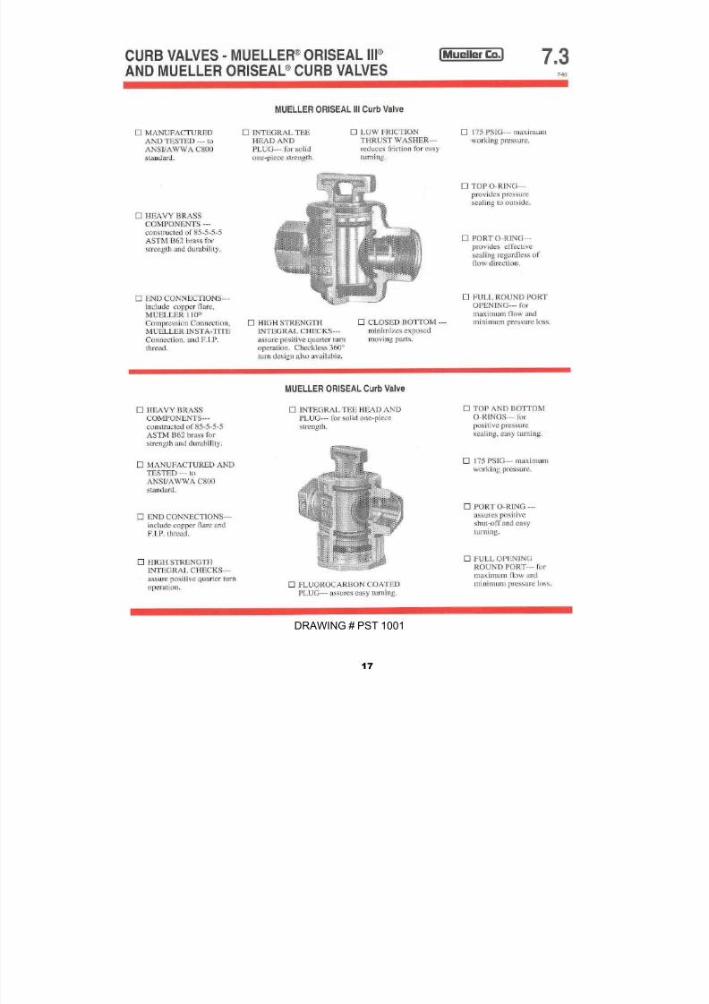
G. CURB STOPS AND VALVES - Curb stops and valves shall be Mueller H-15209 with a
conductive compression outlet connection for CTS OD tubing-all valves shall be left
opening (counter-clockwise)- both ends Quarter turn check or Mueller H-15204
copper flare nut-both ends Quarter turn check (Drawing PST 801- PST 1001)
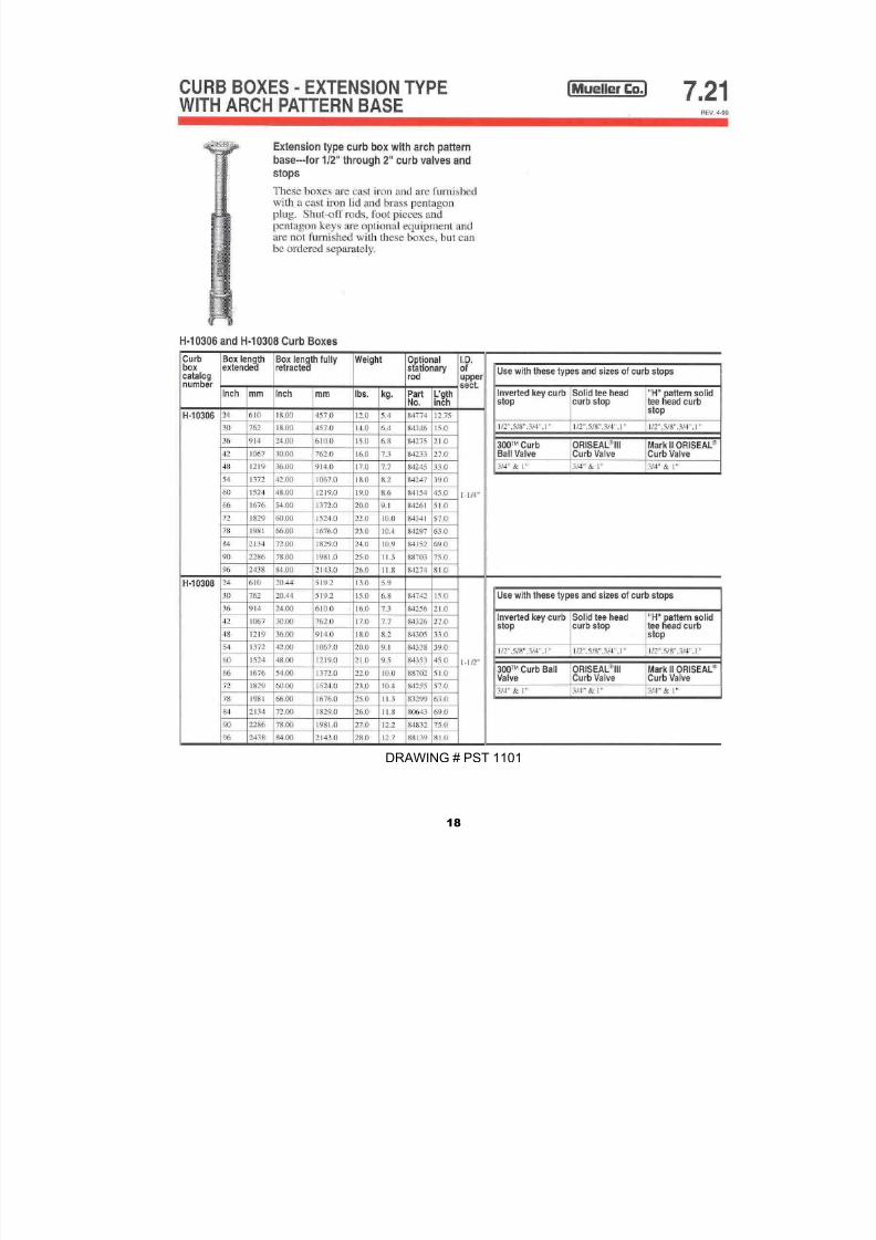
H. CURB VALVE BOX WITH ROD - Curb valve boxes shall be Mueller H-10314
extension type with arch pattern base and shall be adjustable in height from 42
inches to 60 inches. Curb boxes shall have one piece lids with two holes for 1”
services or two piece lids with brass pentagon plug for 2” services and shall have thword “WATER” cast neatly on the lid. (Drawings PST 1101 and PST 1201)
I. ROADWAY VALVE BOX - Valve boxes shall be genuine buffalo style cast iron, size
No. 22 (Series 6850), adjustable screw type with 5 1/2" shaft and of such length to
extend from valve to finished grade, five foot bury. Valve box covers shall be marke
“WATER”. (Drawing PST 1301)

7/27/2019 Water Sewer Std
http://slidepdf.com/reader/full/water-sewer-std 13/67
6
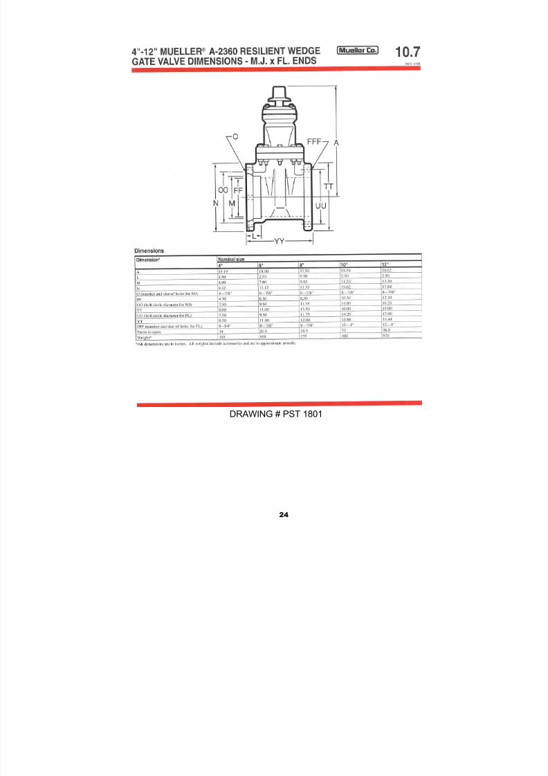
J. GATE VALVE - Gate valves shall be either double disc Mueller A-2380-20 or resilient
seat wedge Mueller A-2360-20 complying with AWWA C509. All gate valves shall
have a non-rising stem (NRS) with rubber “O” ring packing seals and shall be
furnished with mechanical joints unless otherwise specified. All resilient seated gate
valves shall be designed for 400 P.S.I. test pressure and a maximum workingpressure of 200 psi with no leakage, unless otherwise noted. All valves shall be
installed in a vertical position and open by turning to the left (counterclockwise). If
flanged-end valves are used, stainless steel Type 304 bolts and nuts shall be used.
(PST 1501 - PST 2001)
K. FIRE HYDRANTS - Fire hydrants shall be first line hydrants and shall conform as a
minimum to the American Water Works Association standard C502, latest revision
thereof. Hydrants shall be Mueller Super Centurion No. A-423. Hydrants shall be
compression main valve type of the center stem construction, closing with the line
pressure and shall be designed for a working pressure of 150 PSI in ordinary waterworks service . Fire Hydrants shall meet the following specifications (Drawings #PST
2101 and PST 2201):
1. Inlet Connection - The inlet shall be a 6 inch bell end connection suitable for
mechanical or push-on joint of Class 52 ductile iron spigot end pipe.
2. Hoses and Nozzles - Each hydrant shall have two 2 ½ inch hose nozzles and
one 4 ½ inch bronze pumper nozzle. Hydrants shall be furnished with a five
foot bury line and shall be self-draining. The hydrants shall open by turning lef
(counterclockwise). The equipment shall be new and all applicable warrantie
shall be submitted to the City upon delivery.
3. Mueller No. A-423 Centurion Fire Hydrant Main Valve and Seat Ring. - All
hydrants shall have a main valve opening of at least 5 1/4 inches in diameter
The valve gasket shall be of synthetic rubber at least 1 inch thick.The design o
the main valve assembly shall be such that, the main valve and seat ring may
be removed from above ground by a wrench through the upper barrel witho
excavation. The bronze seat ring shall thread directly into a bronze drain ring
forming an all bronze waterway. All bronze internal parts shall be ASTM B-62
grade All pressure seals shall be accomplished by the use of “O” ring seals.
3a. Hydrant Barrel - The lower barrel shall be a one piece casting with
integrally cast lower and upper flanges.
The design of the hydrant shoe shall be such that it may be removed
from the lower barrel without disturbing the main valve seal. The lower
barrel shall also be removable from the shoe without disturbing the mai
valve seal. The shoe shall be contoured smoothly to assure maximum
flow. The interior of the shoe shall be coated with a two-part ,non-toxic

7/27/2019 Water Sewer Std
http://slidepdf.com/reader/full/water-sewer-std 14/67
7
thermo-setting epoxy. The coating shall be formulated from materials
deemed acceptable per Food and Drug Administration Document Title
21, Section 121.2514, resins and polymeric coatings. The inlet connectio
of the hydrant shoe shall be six (6) inch mechanical joint.
A two-part safety flange shall accomplish the connection of theupper barrel to the lower barrel. The upper barrel shall be capable
of rotating a full 360o without full disassembly at the ground line.
3b. Valve and Drain Stem. -The main valve stem shall be a two piecedesign joined at the safety flange area by a steel torque- divertingcoupling. The coupling shall be affixed to the main valve stem bymeans of stainless steel clevis pins and stainless steel cotter pins. Thmain valve stem in the lower barrel shall be coated with a two-parnon-toxic epoxy. The coating shall be formulated from materialsdeemed acceptable per Food and Drug Administration DocumenTitle 21, Section 121.2514, resins and polymeric coatings. The
hydrants shall have double drain valves to facilitate completedrainage of the barrel.
The bonnet section shall be constructed of a one-piece casting anshall have a seal oil reservoir as an integral part. The oil reservoir wbe such that it has two “O” ring seals at the bottom, one serving asa pressure seal, the other as a dirt seal. There shall also be “O” ringseals between the bronze hold down nut and the bonnet, betweethe hold down nut and the operating nut. The oil reservoir will besuch that the oil is recycled and all working parts in the bonnetsection are lubricated each time the hydrant is fully opened andclosed. The one piece operating nut will be such that there is ananti-friction washer above the thrust collar to reduce operating
torque and decrease wear. Attached to the operating nut thereshall be a ductile iron weather cap.
4. Detailed Specifications
One 2-½ inch hose nozzle rated at 250 GPM. (0.25 P.S.I. PressureLoss)
Two 2 ½ inch hose nozzles rated at 500 GPM (1.00 P.S.I. PressureLoss)
One 4 ½ inch steamer nozzle rated at 1,000 GPM (2.20 P.S.I. Pressure loss)
Siize of main valve opening 5 ¼ inchesSize of inlet 6 inchesType of inlet Mechanical joint with
accessoriesHose nozzles 2-2 ½ inchesSteamer nozzles 1-4 ½ inchesHose nozzle threads National Standard 3.0686 O.D. x 7 T.P.I.
Steamer nozzle threads National Standard 5.7609 O.D. x 4 T.P.I.
Size and shape of operating nut 1 ½ inch pentagon
Direction of opening Left

7/27/2019 Water Sewer Std
http://slidepdf.com/reader/full/water-sewer-std 15/67
8
DRAWING # PST 101
Depth of bury 5 feet
L. APPROV
L - All
products
shall be
approvedby the Ci
of Orrville
prior to
installatio

7/27/2019 Water Sewer Std
http://slidepdf.com/reader/full/water-sewer-std 16/67
9
DRAWING # PST201

7/27/2019 Water Sewer Std
http://slidepdf.com/reader/full/water-sewer-std 17/67
10
DRAWING # PST 301

7/27/2019 Water Sewer Std
http://slidepdf.com/reader/full/water-sewer-std 18/67
11
DRAWING # PST 401

7/27/2019 Water Sewer Std
http://slidepdf.com/reader/full/water-sewer-std 19/67
12
DRAWING # PST501
DRAWING # PST 501A

7/27/2019 Water Sewer Std
http://slidepdf.com/reader/full/water-sewer-std 20/67
13
DRAWING # PST 601

7/27/2019 Water Sewer Std
http://slidepdf.com/reader/full/water-sewer-std 21/67
14
DRAWING # PST 701

7/27/2019 Water Sewer Std
http://slidepdf.com/reader/full/water-sewer-std 22/67
15
DRAWING # PST 801

7/27/2019 Water Sewer Std
http://slidepdf.com/reader/full/water-sewer-std 23/67
16
DRAWING # PST 901
7/27/2019 Water Sewer Std
http://slidepdf.com/reader/full/water-sewer-std 24/67
17
DRAWING # PST 1001
7/27/2019 Water Sewer Std
http://slidepdf.com/reader/full/water-sewer-std 25/67
18
DRAWING # PST 1101

7/27/2019 Water Sewer Std
http://slidepdf.com/reader/full/water-sewer-std 26/67
19
DRAWING # PST 1201

7/27/2019 Water Sewer Std
http://slidepdf.com/reader/full/water-sewer-std 27/67
20
DRAWING # PST 1301

7/27/2019 Water Sewer Std
http://slidepdf.com/reader/full/water-sewer-std 28/67
22
DRAWING # PST 1601

7/27/2019 Water Sewer Std
http://slidepdf.com/reader/full/water-sewer-std 29/67
23
DRAWING # PST 1701
7/27/2019 Water Sewer Std
http://slidepdf.com/reader/full/water-sewer-std 30/67
24
DRAWING # PST 1801

7/27/2019 Water Sewer Std
http://slidepdf.com/reader/full/water-sewer-std 31/67
25
DRAWING # PST 1901

7/27/2019 Water Sewer Std
http://slidepdf.com/reader/full/water-sewer-std 32/67
27
DRAWING # PST 2101

7/27/2019 Water Sewer Std
http://slidepdf.com/reader/full/water-sewer-std 33/67
28
DRAWING # PST 2201

7/27/2019 Water Sewer Std
http://slidepdf.com/reader/full/water-sewer-std 34/67
29
SECTION IV
REMOTE WATER METER INSTALLATION
This specification is the installation of residential 5/8 inch” x ¾ inch remote water meters. A
commercial and industrial meters must be approved on an individual basis as per
the General Rules and Regulations of the Water Division. All meter installations shall
be planned and constructed for remote reading devices. The owner or contractor responsible for contacting the Orrville Utilities so that the remote wire installation can
be made prior to enclosing walls, ceilings, etc.
A. GENERAL SPECIFICATIONS -All meter installations shall be inspected and approved by the
Orrville Utilities before permanent water service is established. If the meter installation does not
meet Department of Public Utility Standards, the water will be shut off at the curb valve and water
service shall not be established until the meter installation is revised and subsequently inspected and
approved. A trip charge based on the current applicable rate is found in the General Rules and
Regulations of the Meter Department, shall be charged for all inspection and turn on requests excep
for the initial request.
No water meter will be set until all appropriate lines have been inspected and approved by theOrrville Utilities inspector. This item refers to both water and sewer lines.
Meters shall not be installed in any inaccessible places such as, behind water heaters, furnaces,
washers and dryers, in crawl spaces, bathrooms or bedrooms. In addition, meters shall not be
installed in locations that might be exposed to extreme temperatures, either hot or cold, unless
proper protection of the meter and lines is provided, and the installation is approved by the
Department of Public Utilities.
Meters may be installed in outdoor pits of proper construction and protection. Meter pits, if
permitted, shall receive specific approval by the Director because of the possibility of groundwateintrusion. They shall meet the specifications of the utility and be furnished, owned and maintaine
by the consumer. Water meters shall be installed as follows:
* Reference next page for Meter Instruction Drawing (# PST 2301)
WATER METER INSTALLATION IN OUTSIDE PIT
1. Meter pit cannot be under trailer.
2. Meter pit must be accessible at all times.
3. Box must be kept in good repair at all times.
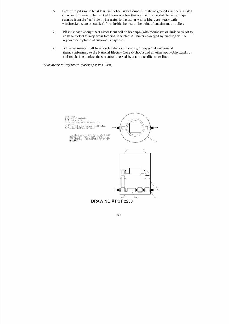
4. Meter pit box may be made of treated wood or equivalent wood with minimum thickness of
inch and insulate with 2 inch thick Styrofoam or a manufactured Mueller/McCullough mete
vault (or approved equal). Lid must be a removable cover with an opening size no smaller
than 20 inches by 28 inches. (Drawing # PST 2250)
5. Meter pits located in low or wet areas must be designed to prevent water from filling pit.
7/27/2019 Water Sewer Std
http://slidepdf.com/reader/full/water-sewer-std 35/67
30
DRAWING # PST 2250
6. Pipe from pit should be at least 34 inches underground or if above ground must be insulated
so as not to freeze. That part of the service line that will be outside shall have heat tape
running from the “in” side of the meter to the trailer with a fiberglass wrap (with
windbreaker wrap on outside) from inside the box to the point of attachment to trailer.
7. Pit must have enough heat either from soil or heat tape (with thermostat or limit so as not to
damage meter) to keep from freezing in winter. All meters damaged by freezing will be
repaired or replaced at customer’s expense.
8. All water meters shall have a solid electrical bonding “jumper” placed around
them, conforming to the National Electric Code (N.E.C.) and all other applicable standards
and regulations, unless the structure is served by a non-metallic water line.
* For Meter Pit reference (Drawing # PST 2401)

7/27/2019 Water Sewer Std
http://slidepdf.com/reader/full/water-sewer-std 36/67
31
THIS SPECIFICATION IS FOR THE INSTALLATION OF RESIDENTIAL 5/8 x 3/4 WATER
METERS WITH REMOTE READER HEAD. ALL COMMERCIAL AND INDUSTRIAL
INSTALLATIONS MUST BE APPROVED ON AN INDIVIDUAL BASIS AS PER THE GENERAL
RULES AND REGULATIONS OF THE WATER DIVISION.
1. WATER METERS SHALL BE INSTALLED HORIZONTALLY:
2. NO LESS THAN FOURTEEN (14") IN. FROM THE FLOOR TO C/L OF METER.
3. NO MORE THAN FOURTY-EIGHT (48") IN. FROM THE FLOOR TO THE C/L OF METER.4. NO LESS THAN SIX (6") IN. FROM THE ENTRANCE WALL TO C/L OF METER.
5. NO MORE THAN TWO (2') FT. FROM THE POINT OF ENTRANCE IN ANY DIRECTION.
6. NO LESS THAN TWENTY-FOUR (24") IN. OF ACCESSIBLE WORKING SPACE IN FRONT O
THE METER.
7. NO LESS THAN TWENTY-FOUR (24") IN. OF WORKING SPACE ABOVE THE METER.
8. NO LESS THAN SIX (6") IN. OF WORKING SPACE BELOW THE METER.
9. A VALVE SHALL BE INSTALLED ON BOTH SIDES OF THE METER.
10. REMOTE WATER METER HEAD TO BE LOCATED BESIDE ELECTRIC METER, A
MINIMUM OF SIX (6") INCHES, AND A MAXIMUM OF TWENTY-FOUR (24") INCHES. (SEE
ILLUSTRATION. LOCATION W, X, Y, OR Z.
11. ALL METER INSTALLATIONS SHALL BE PLANNED & CONSTRUCTED FOR REMOTE
READING DEVICES. THE OWNER/OPERATOR IS RESPONSIBLE FOR CONTACTING THE
DEPT. OF PUBLIC UTILITIES FOR LOCATION APPROVAL SO THAT THE REMOTE WIRE
CONDUIT INSTALLATION CAN BE MADE PRIOR TO ENCLOSING WALLS, CEILINGS, ETC.
OPTIONAL
CONDUIT ROUTE
ELECTRIC METER
#3
ELECT
METERX
Z
W
Y
EXTERIOR FRONT VIEW
(A&B)
(C&D)
FRONT SECTION
INSTALL RIGID
ELECTRICAL
CONDUIT WITH
APPROVED
FITTINGS
CONDUIT STUBBED
TO OUTSIDE
OPTION
FINISHED GRADE
4' MIN
(F)
(E)
(G)
6"-24"
WATER LINE
DRAWING # PST 2301

7/27/2019 Water Sewer Std
http://slidepdf.com/reader/full/water-sewer-std 37/67
34
4. Air Removal - Before applying the specified test pressure, air shall be expelled
completely from the pipe, valves, and hydrants. If permanent air vents are no
located at all high points, the contractor shall install corporation cocks at suc
points so that the air can be expelled as the line is filled with water. After all
the air has been expelled, the corporation cocks shall be closed and the testpressure applied. At the conclusion of the pressure test, the corporation cock
shall be removed and plugged or left in place at the discretion of the City.
B. LEAKAGE TEST - The leakage test shall be conducted concurrently with the pressure
test.
1. Leakage Defined - Leakage shall be defined as the quantity of water that mus
be supplied into the newly laid pipe, or any valved section thereof, to maintain
pressure within five (5) psi (0.35 Bar) of the specified test pressure after the air in
the pipeline has been expelled and the pipe has been filled with water.
Leakage shall not be measured by a drop in pressure in a test section over a
period of time.
2. Allowable Leakage - No pipe installation will be accepted if the leakage is
greater than that determined by the following formula:
L = SD P
133200
in which L is the allowable leakage, in gallons per hour; S is the length of pipe
tested, in feet; D is the nominal diameter of the pipe, in inches; and P is the
average test pressure during the leakage test, in pounds per square inch
gauge. In metric units,
Lm = SD P
2816
in which Lm is the allowable leakage, in liters per hour; S is the length of the
pipe tested, in meters; D is the nominal diameter of the pipe in inches; and Pis
the test pressure in Bars. These formulas are based on an allowable leakage o
11.65 gpd, per mile, per inch nominal diameter at a pressure of 150 psi.
3. Allowable Leakage at various pressures is shown in Table 6.

7/27/2019 Water Sewer Std
http://slidepdf.com/reader/full/water-sewer-std 38/67
35
Table 6
Allowable Leakage per 1000 ft (305 m) of Pipeline*-gph#
Nominal Pipe Diameter - inches
Average ------------------------------------------------------------------------------------------------------- Test Pressure 3 4 6 8 10 12 14 16 18 20 24
PSI (Bar)
-------------------------------------------------------------------------------- -------------------------------------------
-
250 (17) .36 .47 .71 .95 1.19 1.42 1.66 1.90 2.14 2.37 2.85
225 (16) .34 .45 .68 .90 1.13 1.35 1.58 1.80 2.03 2.25 2.70
200 (14) .32 .43 .64 .85 1.06 1.28 1.48 1.70 1.91 2.12 2.55
175 (12) .30 .40 .59 .80 .99 1.19 1.39 1.59 1.79 1.98 2.38
150 (10) .28 .37 .55 .74 .92 1.10 1.29 1.47 1.66 1.84 2.21
125 ( 9) .25 .34 .50 .67 .84 1.01 1.18 1.34 1.51 1.68 2.01100 ( 7) .23 .30 .45 .60 .75 .90 1.05 1.20 1.35 1.50 1.80
-------------------------------------------------------------------------------- -------------------------------------------
* - If the pipeline under test contains sections of various diameters, the allowable
leakage will be the sum of the computed leakage for each size.
# - To obtain leakage in liters/hour, multiply the values in the table by 3.785.
4. When testing against closed metal-seated valves, an additional leakage
per closed valve of 0.0078 gal/h/in. (0.0012 L/h/mm) of nominal valve size
shall be allowed.
5. When hydrants are in the test section, the test shall be made against the
closed hydrant.
6. Acceptance of Installation: Acceptance shall be determined on the
basis of allowable leakage. If any test of pipe laid discloses leakage
greater than that specified in Section II.B, the contractor shall, at his ownexpense, locate and make repairs as necessary until the leakage is within
the specified allowance.
7. All visible leaks are to be repaired regardless of the amount of leakage.

7/27/2019 Water Sewer Std
http://slidepdf.com/reader/full/water-sewer-std 39/67
36
C. DISINFECTION
1. Newly installed or repaired water main shall be disinfected in accordance
with AWWA C651 Standards. The forms of chlorine that may be used areliquid chlorine, sodium hypochlorite and calcium hypochlorite granules or
tablets using the continuous feed, slug or tablet method. The continuous
feed method is the most suitable for general applications. Following
chlorination, the main should be flushed as soon as possible since
prolonged exposure to high concentrations of chlorine might damage the
asphaltic seal coat.
BASIC DISINFECTION PROCEDURE:
The basic disinfection procedure consists of:
a. Inspecting all materials to be used to ensure the integrity of the
materials.
b. Preventing contaminating materials from entering the water main
during storage, construction or repair and noting potential
contamination at the construction site.
c. Removing by flushing or other means, those materials that may have
entered the water main.
d. Chlorinating any residual contamination that may remain and
flushing the chlorinated water from the main.
e. Protecting the existing distribution system from backflow caused by
hydrostatic pressure test and disinfection procedures.
f. Documenting that an adequate level of chlorine contacted each
pipe to provide disinfection.
g. Determining the bacteriological quality by laboratory test afterdisinfection.
h Final connection of the approved new water main to the active
distribution system.
Upon filling of the water mains, the potable water shall be chlorinated so
that after a 24 hour holding period in the main there will be a free chlorine

7/27/2019 Water Sewer Std
http://slidepdf.com/reader/full/water-sewer-std 40/67
37
residual of not less than 10 mg/l. After the holding period the heavily
chlorinated water shall be flushed from the main until chlorine
measurements show the concentration in the water leaving the main is
below 2 mg/l. After flushing and before the new water is connected to the
distributions system, two consecutive sets of acceptable samples, taken atleast 24 hours apart, shall be collected from a sampling tap. No hose or
fire hydrant shall be used in the collection of samples.
All samples shall be tested for bacteriological quality in accordance with
Standard Methods for Examination of Water & Wastewater; and shall show
the absence of coliform organisms. If the initial disinfection fails to produce
satisfactory bacteriological results, the new main may be reflushed and
shall be resampled. If check samples also fail, the main shall be
rechlorinated by the continuous feed or slug method until satisfactory
results are obtained. (You may use the above method or other AWWA
approved disinfection methods).

7/27/2019 Water Sewer Std
http://slidepdf.com/reader/full/water-sewer-std 41/67
SEWER
SECTION

7/27/2019 Water Sewer Std
http://slidepdf.com/reader/full/water-sewer-std 42/67
39
SEWER
GENERAL RULES AND REGULATIONS
1. All sewer lines shall be installed with a minimum of four (4) feet of cover.
7. Sizing of sanitary sewer mains to accommodate future growth shall be
determined by Orrville Utilities.
3. All costs for sewer system improvements, including necessary over-sizing, shall
be borne by the developer.
4. All sewer mains shall be extended to the farthest property line of the
developer to accommodate future growth. Said main extensions shall be at
the expense of the developer.
5. All sewer installations shall be bedded in, and backfilled to 12 inches above
the pipe with sand or pea gravel. All trenches under paved areas shall be
backfilled and properly compacted to finished grade with sand or gravel.
6. All sewer pipes, fittings, hydrants, manholes, manhole castings and lids, meter
pits and other appurtenances and incidentals shall conform to specifications
and standards as specified in the “WATER & SEWER PIPE STANDARDS” for the
Orrville Utilities.
7. All sanitary sewer service laterals from the main to the building may be vitrifiedclay pipe meeting ASTM C-700 material specification and ASTM C-425 joint
specification or approved PVC pipe conforming to ASTM D3034 material
specification and ASTM D 3212 joint specification. Said sanitary sewer shall be
a minimum of six (6) inches in diameter and installed with a minimum slope of
one (1) percent. Where an existing four (4) inch “Y” branch is found, and
deemed serviceable by the City, the building sewer may be four (4) inches in
diameter and installed with a minimum slope of two (2) percent.
8. All gravity sanitary sewer mains to be maintained by the City shall be a
minimum of eight (8) inches in diameter and be constructed of vitrified claypipe meeting ASTM C-700 material specification and ASTM C-425 joint
specification or PVC pipe conforming to ASTM D3034 material specification
and ASTM D 3212 joint specification or ASTM F 1803 and F949.
PVC gravity sanitary sewer pipe and fittings conforming to ASTM D3034 shall
be allowed for sanitary sewers when the depth of cover is greater than four
(4) feet and no more than twenty (20) feet and when the internal pipe
diameter is less than or equal to ten (10) inches.

7/27/2019 Water Sewer Std
http://slidepdf.com/reader/full/water-sewer-std 43/67
40
PVC gravity sanitary sewer pipe and fittings conforming to ASTM F 1803 and F
949 shall be allowed for sanitary sewers greater than ten (10) inches in internal
diameter and greater than twenty feet (20) in depth.
9. Force main sanitary sewers shall be constructed of Class 52 cement linedductile cast iron pipe or PVC pipe and fittings, which shall conform to ASTM D
2241, SDR21, 200 psi.. They shall be a minimum of two (2) inches in diameter
and have a minimum of four (4) feet of cover.
10. A manufacturer certificate that the pipe and fittings were manufactured and
tested in accordance with the appropriate ASTM specification must
accompany all PVC pipes and fittings. Said certificate shall be submitted to
the Orrville Utilities prior to the installation of said pipe.
11. All sanitary sewer manholes installed in, or tributary to, the City of Orrvillesanitary sewer system shall be precast concrete meeting ASTM C-478 material
specification and ASTM C-443 joint specification. They shall be installed at a
maximum of 400 feet apart and at the end of all sewer mains and in changes
in sewer line direction greater than 15 degrees.
12. All sanitary sewer manholes to be maintained by the City shall be covered
with Neenah R-1762 manhole frame and lid as per Section VI herein. Also East
Jordan #1661 with type A solid cover ( TABLE 11).
13. Grease traps must be installed according to Wayne County Health
Department specifications when required. Detailed drawing of minimum
design requirements attached (Reference next page for drawing # PST
2401A)

7/27/2019 Water Sewer Std
http://slidepdf.com/reader/full/water-sewer-std 44/67
41
4'-8"
11"INLET BAFFLE
3"
15" OR 24"
OPTIONAL RISER STANDARD RISER
12"
24"
1'-2"
4'-5"
6'3" 3"
SECTION "A-A"
TOP VIEW
1'-6" VESTAL LID
2"2"
11"
4'-2"
5'-7"
3"
3"
3'-7"3" 3"
SECTION "B-B"
500 GALLON GREASE TRAP
GRADE
A A
B
B
RISERS
INLET
OUTLET
24" SEALED MANHOLE COVER
RING WITH 4 SCREWS
GREASE INTERCEPTOR
12"
OUT 4"
CLEAN OUTS
4" 4"
1000 GAL. MIN.
NO BAFFLE'S
6"
GRADE
IN
GRADE
DRAWING # PST 2401A

7/27/2019 Water Sewer Std
http://slidepdf.com/reader/full/water-sewer-std 45/67
42
SECTION IV- SANITARY SEWER PIPE
SANITARY SEWER PIPE (GRAVITY)
MATERIAL
SPECIFICATION
JOINT
SPECIFICATION
A. VITRIFIED CLAY SEWER MAINS AND
LATERALS ASTM C - 700 ASTM C - 425
B. TYPE PSM POLYVINYL CHLORIDE (PVC)
MAIN LATERAL SEWER PIPE < 18 inches ASTM D - 3034 ASTM D - 3212
C. PVC SANITARY SEWER & FITTINGS > 18
inches
ASTM F - 1803
ASTM F - 949
Table 7
Minimum Wall Thickness
4" - .120
6" - .180
8" - .240
10" - .300
12" - .360
15" - .437Table 8
SANITARY SEWER FORCE MAIN PIPE
A. POLYVINYL CHLORIDE (PVC) PIPE, SDR-21 ASTM D - 2241
B. POLYVINYL CHLORIDE PRESSURE PIPE AWWA C - 900
C. CLASS 52 DUCTILE CAST IRON PIPE ANSI - A21.51
Table 9
SANITARY SEWER MANHOLES, CASTINGS & LIDS
MATERIAL
SPECIFICATION
JOINT
SPECIFICATION
A. PRECAST CONCRETE SANITARY
SEWER MANHOLES ASTM C - 478 ASTM C - 443
B. MANHOLE FRAMES & LIDS, NEENAH R-1762 WITH SOLID LID, TOTAL WEIGHT 350 LBS.Table 10

7/27/2019 Water Sewer Std
http://slidepdf.com/reader/full/water-sewer-std 46/67
43
F
SANITARY SEWER
BOTTOM REINFORCING
KNOBS 1.5" DIA. X 3/8" HIGHTOP VIEW
LID
G
KEY TO DIMENSIONSMANHOLE COVER
ORRVILLE MUNICIPAL UTILITIESMANHOLE CASTING FRAME AND
LID STANDARD
D
C
IDENTIFICATION CODE
A = 22.25"
B = 1"
C = 21"
D = 22.5"
E = 30"
F = 9.75"
G = "SANITARY SEWER"
CAST INTO LID
A
B
E
DRAWING # PST 2501
SECTION VII
SPECIFICATIONS FOR MANHOLE FRAMES, LIDS AND ADJUSTING RINGS
This specification is for Ferrous Castings. Materials used in the manufacture of
castings shall conform to ASTM, AASHTO, ASA, MIL, AMS or Federal Specifications forGray Iron or other applicable standards. They shall be of uniform quality, free from
blowholes, porosity, hard spots, shrinkage distortion or other defects. They shall be
smooth and well cleaned by shotblasting. They shall be coated with asphalt paint,
which shall result in a smooth coating, tough and tenacious when cold, not tacky or
brittle.
A. GENERAL SPECIFICATIONS - All castings shall be manufactured true to
pattern; component parts shall fit together in a satisfactory manner. Round
frames and covers shall have machined bearing surfaces to prevent rocking
and rattling under traffic. As a minimum, the castings shall conform to ASTM A48, Class 30 with tensile strength of 30,000 pounds per square inch.
The lids shall have cast in them for identification, the words SANITARY SEWER.
7/27/2019 Water Sewer Std
http://slidepdf.com/reader/full/water-sewer-std 47/67
44
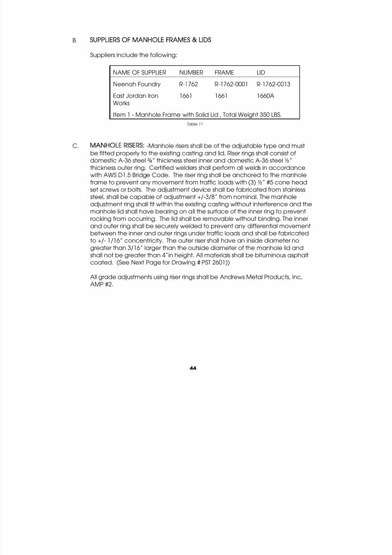
B. SUPPLIERS OF MANHOLE FRAMES & LIDS
Suppliers include the following:
NAME OF SUPPLIER NUMBER FRAME LIDNeenah Foundry R-1762 R-1762-0001 R-1762-0013
East Jordan Iron
Works
1661 1661 1660A
Item 1 - Manhole Frame with Solid Lid , Total Weight 350 LBS.
Table 11
C. MANHOLE RISERS: -Manhole risers shall be of the adjustable type and must
be fitted properly to the existing casting and lid. Riser rings shall consist of
domestic A-36 steel ¾” thickness steel inner and domestic A-36 steel ½”
thickness outer ring. Certified welders shall perform all welds in accordance
with AWS D1.5 Bridge Code. The riser ring shall be anchored to the manhole
frame to prevent any movement from traffic loads with (3) ½” #5 cone head
set screws or bolts. The adjustment device shall be fabricated from stainless
steel, shall be capable of adjustment +/-3/8” from nominal. The manhole
adjustment ring shall fit within the existing casting without interference and the
manhole lid shall have bearing on all the surface of the inner ring to prevent
rocking from occurring. The lid shall be removable without binding. The inner
and outer ring shall be securely welded to prevent any differential movementbetween the inner and outer rings under traffic loads and shall be fabricated
to +/- 1/16” concentricity. The outer riser shall have an inside diameter no
greater than 3/16” larger than the outside diameter of the manhole lid and
shall not be greater than 4”in height. All materials shall be bituminous asphalt
coated. (See Next Page for Drawing # PST 2601))
All grade adjustments using riser rings shall be Andrews Metal Products, Inc,
AMP #2.

7/27/2019 Water Sewer Std
http://slidepdf.com/reader/full/water-sewer-std 48/67
45
1/2" (12.7) DIA. x 1 1/2" (36.1)
LONG POINTED SET SCREW.
EITHER HEX HEAD OR ALLEN HEAD (STD).
3 EA. (TYPICAL) SPACED AT 120°.
4" INTERMITTENT
1" (25.4)
SECTION A-A
1/4" (6.35)TYP.
3/4" (19.05) BAR STOCK
SEE OPTIONAL CLIP DETAIL
PLAN
EXIST. COVER THICKNESS
HEIGHT OF ADJUSTMENT
1/2" (12.7) BAR STOCK
ANDREWS METAL PRODUCTS
ADJUSTING MECHANISM CONSISTING OF A
STAINLESS STEEL THREADED STUD2 COUPLINGS AND A LOCK NUT.
THE SYSTEM IS CAPABLE OF ADJUSTING
THE RING DIAMETER + OR - 3/8"FROM THE SET DIAMETER.
A
A
4" INTERMITTENT
1/4" (6.35)
OPTIONAL STEEL RETAINING CLIP.
3 EA. (TYPICAL). SEE DETAIL WITH
1/2" (12.7) DIA. x 1 1/2" (36.1)
SPACED AT 120°
TYP.
NOTES:
1. ALL COMPONENTS ARE MANUFACTURED FROM U.S. MADE CARBON STEEL MEETING OR EXCEEDING THE MINIMUM
REQUIREMENTS OF ASTM A-36.
2. THIS SYSTEM IS USED WHEN THE RISE IS GREATER THAN THE LID THICKNESS.
3. MINIMUM HEIGHT OF ADJUSTMENT WITH THIS SYSTEM IS MANHOLE LID THICKNESS + 1/4" (6.35).
4. EACH ADJUSTMENT RING IS CUSTOM FABRICATED FROM MEASUREMENTS PROVIDED WITH EACH ORDER. REQUIREDMEASUREMENTS INCLUDE:
A. EXIST. MANHOLE COVER TOP AND BOTTOM DIAMETER THICKNESS
B. REQUIRED HEIGHT OF ADJUSTMENT FROM TOP OF EXISTING LID TO FINISHED ELEVATION.
C. REQUIRED LENGTH AND TYPE OF RETAINER CLIP (IF REQ'D).
D. WIDTH AND HEIGHT OF EXISTING CASTING BEARING SURFACE.
5. DURING INSTALLATION CHECK FOR FULL BEARING OF LOWER FRAME SECTION ON EXISTING CASTING.
6. DIMENSIONS MAY VARY TO MEET EXISTING FIELD CONDITIONS.
7. RISERS SHALL BE COATED WITH BLACK ASPHALT BITUMINOUS PAINT.
8. DIMENSIONS SHOWN IN BRACKETS ( ) ARE METRIC MILLIMETERS.
EXIS
1/2" (12.7) TYP.
SLIDING EXTERNAL
RING CLOSURE PIECE
CON
EXISTING COVER SIZE + 3/16"
DRAWING # PST 2601

7/27/2019 Water Sewer Std
http://slidepdf.com/reader/full/water-sewer-std 49/67
46
SECTION VIII
SPECIFICATION FOR SANITARY SEWER DROP MANHOLES
This specification is for sanitary sewer drop manholes. Drop manholes may be installed in,
or tributary to, the City of Orrville sanitary sewer system, only when approved by the
Department of Public Utilities. They shall conform to design criteria contained herein.Drop manholes shall not be utilized for immediate changes in sewer elevation of less than
two (2) feet. The drop pipe shall be, as a minimum, 8" in diameter but it shall not be of
lesser diameter than the influent line, which it serves.
For manholes constructed prior to Jan. 1, 1981, which are served by an effluent line with a
diameter smaller than 8", the Orrville Utilities may consider influent lines and drop pipes of
less than 8in diameter but not less than the diameter of the effluent line.
Installation of drop manhole installations shall be in the presence of a qualified inspector
designated by the Department of Public Utilities.
Drop manholes are used to provide for significant changes in grade or elevation resultingfrom the topography of the area. These structures should be used as infrequently as
possible since they are a source of high turbulence in sewage flow. Where hydrogen
sulfide gas (H2S) is present in sewage, agitation turbulence developed by drop manhole
can cause the H2S gas to be released, resulting in severe odor problems and corrosion of
the manhole structure.
Two types of drop manholes are currently accepted.
1) Inside drop manholes (Drawing # PST 2701-A)
2) Outside drop manholes (Drawing # PST 2701-B)
The inside drop is the preferred method because of its economic and maintenance
benefits.
Reference next page (Drawing # PST 2701).

7/27/2019 Water Sewer Std
http://slidepdf.com/reader/full/water-sewer-std 50/67
47
(HALF SECTION)
OUTSIDE DROP
NOTES:
1. DROP IS REQUIRED WHEN INVERT DIFFERENTIAL IS 24" OR GREATER.
2. HEIGHT OF DROP PIPE IS TO BE SHOWN ON THE PLANS OR WILL BE DETERMINED AT THE TIME OF CONSTRUCTION.
3. WHERE CALLED FOR, AND UNLESS OTHERWISE REQUIRED BY THE PLANS, THE OUTSIDE DROP WILL BE CONSTRUCTED WITH NEWMANHOLES.
4. MATERIALS FOR THE TEE, DROP PIPE, AND THE BEND SHALL BE OF ONE TYPE AND BE ONE OF THE FOLLOWING- INSIDE DROP:
CAST IRON OR PVC. OUTSIDE DROP: C.I. SOIL, VIT. SEWER, OR PVC.
5. OUTSIDE DROP PIPES REQUIRE A 5" THICK (MINIMUM) CLASS "C" CONCRETE ENCASEMENT ON THREE SIDES OF PIPE AND TIED TO
MANHOLE WALL WITH 5/8"-"U" RODS x 6" LONG @ 12".
6. INSIDE DROP MAY BE USED ON NEW CONSTRUCTION PROVIDED THAT 60" BASE AND RISER SECTIONS ARE USED.
CHANNEL CLASS
"C" CONC.
(HALF SECTION)
INSIDE DROP
CLASS "C"
CONCRETE
5' MAX SPACING
2 CLAMPS MINIMUM
45° BEND
INSIDE
M. H. WALL
STAINLESS STEEL
BOLTS, (1/2" MIN.)
BANDS AND ANCHORS
D2 (ONE PIECE
VARIABLE LENGTH)
CLASS "C"
CONCRETE
D1 x D1 x D2 TEE
CLASS "C" CONCRETE
AFTER DROP HAS BEEN
CLAMPED IN PLACE
D1
INSIDE
M. H. WALL
PIPE DIAMETER
(HALF SECTION)
OUTSIDE DROP
24"
21"
18"
12"
15"
10"
CLASS "C"
CONCRETE
8"
6"
8"
D1
CLASS "C"
CONCRETE
12"
12"
10"
8"
8"
10"
8"
D2
6"
8"
CLASS "C"
CONCRETE
45° BEND
D2 CLASS "C"
CONCRETE
D1 x D1 x D2 TEE
INSIDE
M. H. WALL
45° BEND
D2
D1 x D1 x D2 TEE
5" MIN.
D1
5" MIN.
D1
A B
DRAWING # 2701

7/27/2019 Water Sewer Std
http://slidepdf.com/reader/full/water-sewer-std 51/67
48
SECTION IX
SERVICE CONNECTIONS
A. PLANNED SERVICE CONNECTIONS -All service connections, installed as a part of
new sanitary sewer main installation, shall be by means of an approved tee, a
minimum of six (6) inches in internal diameter. Said service connection shall be
extended a minimum of three (3) feet into the property to be served, capped
watertight, and the termination location indicated by a treated 2 x 2 marker
extended a minimum of one foot above finished grade.
B. UNPLANNED SERVICE CONNECTIONS - All unplanned service connection methods
must be approved by the Inspector and are at the expense of the Contractor.
They shall be made in the field under observation of the Inspector. Service saddlesmay be installed, either gasketed and clamped or solvent cemented. When a field
cut-in service connection is required, the following precautions should be observed:
1. Carefully cut the opening for the type of fitting to be used.
2. Prevent entrance of foreign material into cut-in pipe opening.
3. Use proper fitting and procedure for installing the field connection.
4. After curing for 24 hours, bed and backfill properly all pipe and fittings. (Note:Solvent welded fittings will gain 50% of full strength after 24 hours of curing time.)
5. Be sure and use ASTM D3034 saddles. Do not confuse with D3033.
C. CONNECTIONS - Connections to pipe of different materials shall be made with
approved adapters. For taps into all known approved solid wall, profile and closed
profile pipe. INSERT TEE fittings, shall be used. Installation must be made according
to INSERTA FITTINGS CO. installation procedures and using approved lubricants. (
Reference next Drawing # PST 2801)

7/27/2019 Water Sewer Std
http://slidepdf.com/reader/full/water-sewer-std 52/67
49
INSERTA-TEE Installation ProcedureUse Hole Saw Core Bits for PVC, Ribbed, and Polyethylene pipe. Use Diamond Core Bits for Concrete, Clay, D.I. andFiberglass Pipe.
TOOLS REQUIRED
1. Hand held drill with hole saws recommended for 4”, 6”, & 8” INSERTA TEES. Tie down coring machinerecommended for 10” & 12” INSERTA TEES and all diamond bits.
2. Bits INSERTA TEE size Bit (hole) Diameter4” 4 ½”
6” 6 ½”8” 8 ¾”
10” 10 7/8”
12” 12 7/8”
15” 15 13/16”
3. 6 lb Hammer and 2”x 4” board.
4. Bottle of INSERTA TEE solution supplied with order.
INSTALLATION PROCEDURE
1. Core the proper size hole. See bit diameters above.
2. Insert the rubber sleeve into the cored hole with the GOLD VERTICAL LINE ON THE RUBBER SLEEVE facing to theside of the mainline. The upper segment should be on top of the wall or rib and the lower segment (PVC,
Ribbed, or Polyethylene pipe only), should be on the inside of the pipe.
3. Apply the INSERTA TEE solution supplied to the inside of the rubber sleeve and outside of the PVC hub adapter.CAUTION! DO NOT use an oil based lubricant.
4. Place the PVC hub adapter into the rubber sleeve. Make sure that the RED VERTICAL LINE ON THE PVC HUB
ADAPTER IS IN LINE WITH THE GOLD VERTICAL LINE ON THE RUBBER SLEEVE.
5. Place the 2”x 4” board on top of the PVC hub adapter.
6. The RED HORIZONTAL LINE AT THE TOP OF THE HUB ADAPTER is a depth mark. This tells the installer just how far todrive the adapter into the rubber sleeve. Using the board and the hammer drive the PVC hub adapter into the
rubber sleeve to where the HORIZONTAL RED LINE ON THE PVC HUB ADAPTER MEETS THE TOP OF RUBBER SLEEVE.
7. Install the stainless band around the top of the rubber sleeve and tighten down.
8. Install side service pipe in normal manner.
RED HORIZONTALLINE
5
7 STAINLESS STEEL
BAND
MATCH RED
HORIZONTAL LINE
6
HUB SDR 35 30343
RED
VERTICAL
LINE
4
IN LINE
IN LINE
RUBBER
SLEEVE
ASTM C-443
1
PVC CONCRETE OR CLAYPLASTIC PROFILEWALL
DRAWING # PST 2801

7/27/2019 Water Sewer Std
http://slidepdf.com/reader/full/water-sewer-std 53/67
50
SECTION X
SPECIFICATION FOR POLYVINYL CHLORIDE (PVC) SEWER PIPE AND
FITTINGS FOR GRAVITY SANITARY SEWER INSTALLATIONS
A. POLYVINYL CHLORIDE (PVC) PIPE -PVC sanitary sewer pipe and fittings conforming to ASTM
D3034 shall be allowed for sanitary sewers when the depth of cover is greater than four (4)
feet and no more than twenty (20) feet and when the internal pipe diameter is less than orequal to ten (10) inches.
PVC sanitary sewer pipe and fittings conforming to ASTM F 1803 and F 949 shall be allowed
for sanitary sewers greater than ten (10) inches in internal diameter and greater than
twenty feet (20) in depth.
1. Home Mark - All pipe spigots shall have a “home” mark to facilitate joint closure.
2. Fittings - PVC fittings shall be factory made and provided with joints of proper design to
connect to the pipe or approved adapters shall be furnished to connect the pipe to
the fittings. Approved adapters shall be provided for connection to pipes of different
materials. All joints and fittings shall be formed to provide a leak-free and easily
assembled system.
3. Lubricant - The proper lubricant recommended by the manufacturer shall be used.
Lubricants that contain petroleum oils or vegetable oils may promote bacterial growth
causing damage to the gaskets or pipe and are not approved.
4. Certificate - A manufacturer’s certificate that the PVC material and pipe was
manufactured and tested in accordance with the appropriate ASTM specification shall
be provided to the inspector prior to installation of the pipe.
5. Manufacturer’s Installation Instructions -All PVC pipes delivered to the job site must be
accompanied by the manufacturer’s installation instructions and guidelines.
6. Straightness - Pipe intended to be straight shall have a maximum deviation from
straightness of 1/16 inch per lineal foot when measured in accordance with ASTM
D2122.
7. Prior Inspection - No pipe and fittings may be installed unless approved by the
Inspector immediately prior to installation and all rejected pieces must be completely
removed from the work site. Pipe acceptable to the Inspector shall be substituted for
rejected pieces at the developers or owners expense. No repairs of pipe or fittings willbe allowed; undamaged lengths of straight pipe may be salvaged by neatly sawing
off the damaged portion of the pipe and re-beveling as described in Section XI.
8. Exposure to Sunlight- The contractor shall take measures to protect the pipe
from prolonged exposure to heat or direct sunlight (ultraviolet rays).

7/27/2019 Water Sewer Std
http://slidepdf.com/reader/full/water-sewer-std 54/67
51
B. PIPE JOINTS - PVC sanitary sewer pipe joints shall be elastomerically gasketed
conforming to ASTM D3212 push-on type.
1. Joint Testing - Testing of PVC sanitary sewer pipe joints, when so directed by the
inspector, shall be performed in accordance with ASTM D3212 for gasketed
joints, with modification as specified below. The Contractor shall provide all
equipment necessary to conduct the pipe joint test.
2. Test Specimens - The inspector may initially and periodically select random
sewer pipe for test purposes. The tests shall be performed on not less than two
specimens and not less than one (1) percent of the total pipe length of each
size and joint type required for the project.
SECTION XI
ISOLATION OF SANITARY SEWER EXTENSIONS
A watertight plug approved by the Orrville Utilities shall be installed by the Owner or his
contractor at his point of connection to the existing sanitary sewer system. The plug shall
be put in place as soon as the sewer extension work commences and shall remain in
place until all improvements are approved by the Orrville Utilities and said development is
formally accepted by the Council of the City of Orrville. Approval by the Orrville Utilities
consists of the following various stages and/or items as follows:
# Plan submittal to City of Orrville for review and approval.
# Payment of all applicable deposits, fees, etc .
# Construction inspection and approval prior to backfilling trench.
# Sewer line cleaning, testing and approval.
# All manholes brought to finished grade and properly sealed and grouted.
# All sewer improvements have been constructed as per the requirements of theapproved construction plans and specifications and have passed inspection andtesting. Refer to Section XII, Inspection & Testing.

7/27/2019 Water Sewer Std
http://slidepdf.com/reader/full/water-sewer-std 55/67
52
DRAWING # PST 2901

7/27/2019 Water Sewer Std
http://slidepdf.com/reader/full/water-sewer-std 56/67
53
SECTION XII
SANITARY SEWER PIPE INSTALLATION
A. SAFETY - For the security and safety of persons in and adjacent to trenches or
construction operations, the safety regulations of the appropriate federal, state
and local agency(s) shall be adhered to.
B. HANDLING - Pipe, fittings, manhole sections, and accessories shall be loaded and
unloaded by lifting with hoists or skidding so as to avoid shock or damage. Under
no circumstances shall such materials be dropped. Pipe handled on skidways shall
not be skidded or rolled against other pipe. Pipe and fittings shall be lowered
gently into the trench. The inspector will reject any pipe or fittings dropped into the
trench.
C. PROTECTION OF TREES - Special care shall be taken to avoid damage to trees
and their root systems. Any damage incurred by trees, shrubs or lawns are the sole
responsibility of the contractor.
D. DE-WATERING -Should water be encountered, the Contractor shall furnish and
operate suitable pumping equipment of such capacity adequate to dewater the
trench. The trench shall be sufficiently dewatered so that the laying and joining of
the pipe is made in the dry. The Contractor shall convey all trench water to a
natural drainage channel or storm sewer without causing any property damage in
accordance with the Ohio Environmental Protection Agency’s (OEPA)
requirements contained in the National Pollutant Discharge Elimination System
(NPDES) program. Trench water may not be conveyed to a sanitary sewer at anytime and shall be conveyed without causing any property damage.
E. CONSTRUCTION EQUIPMENT - Where sewers are located in or adjacent to
pavements, all digging, backfilling and materials handling equipment shall have
rubber tires. Crawler equipment shall be permitted when there is no danger of
damaging pavements or walkways. Any damages incurred to pavements,
sidewalks, etc., is the sole responsibility of the contractor.
F. EXCAVATION AND CONSTRUCTION MATERIALS - All excavated material and all
construction materials used in prosecution of the work shall be deposited so as notto endanger the work or workers, create unnecessary annoyance to the public or
interfere with natural drainage courses. During the progress of the work, all material
piles shall be kept trimmed up and maintained in a neat, workmanlike manner.

7/27/2019 Water Sewer Std
http://slidepdf.com/reader/full/water-sewer-std 57/67
54
G. TRENCH SUPPORTS - Unsupported open cuts for sanitary sewers shall not be
permitted where trenching may cause unnecessary damage to street or sidewalk
pavement, trees, structures, poles, utilities, or other private or public property.
During the progress of the work, whenever and wherever it is necessary, the
Contractor shall, at his expense, support the sides of the excavation by adequate
and suitable sheeting, shoring, bracing, or other approved means. Such trench
support material and equipment shall remain in place until backfilling operationshave progressed to the point where the supports may be withdrawn without
endangering property. In lieu of removing all the sheeting, the Contractor may cut
off the sheeting two (2) feet above the top of the pipe and remove the upper
portion. If all the sheeting is to be removed, it shall be removed without causing
damage to the pipe.
H. NOISE, DUST, AND ODOR CONTROL -The Contractor’s construction activities shall
be conducted so as to eliminate all unnecessary noise, dust, and odors.
I. ALIGNMENT AND GRADE- Proper alignment and grade is the responsibility of theContractor and he shall control his line and grade by use of:
1. Batter Boards - If batter boards are utilized, line and grade stakes shall be
placed at regular intervals, not to exceed 25 feet, at some convenient
offset from the centerline of the pipe. Batter boards shall be carefully
placed immediately following the excavating equipment and a
continuous check on trench depth shall be maintained. Suitable
equipment, supplied by the contractor, for measuring from a line drawn
taut over the batter boards shall be utilized. Such line shall be carefully
located on the batter boards on the centerline of the pipe. In no event
will pipe be laid unless a minimum of three batter boards are in place
and checked.
2 Laser Beam - Prior to the use of a laser beam, the contractor shall furnish
a complete description of all equipment to be used, methods of use and
proof of competency of the operator. If approved by the inspector, the
Contractor may elect to use a laser beam as an alternative to utilizing
batter boards for horizontal and vertical control of the sewer. If a laser
beam is to be utilized, line and grade stakes shall be placed at 25 feet
and 50 feet from the downstream manhole and then placed at every
100-foot station to the next manhole. The laser beam shall be set up insuch a manner that the alignment of the beam is through the pipe
directly on the centerline of the pipe or outside the pipe directly above
and parallel to the centerline of the pipe.

7/27/2019 Water Sewer Std
http://slidepdf.com/reader/full/water-sewer-std 58/67
55
If the laser unit is set up on the centerline of the pipe, a blower shall be
used to provide positive continuous air circulation within the pipe. A
target shall be established on line and grade to provide a method of
checking the setting of the laser beam as construction progresses. The
Contractor shall provide means to ensure the grade pole is plumb when
checking pipe grade. The grade pole shall be set on the invert of the
pipe when checking alignment and grade. Should, in the opinion of theinspector, the laser method be found to be unsatisfactory, the contractor
shall discontinue its use and complete the job using batter boards.
J. PIPE JOINT INSTALLATION - The preparation and assembly of the gasketed joint
shall be performed as recommended by the pipe manufacturer. The elastomeric
gaskets may be supplied separately in cartons or pre-positioned in the bell joint at
the factory. When gaskets are color coded, be sure to consult the pipe
manufacturers literature for the significance.
Prior to assembly, clean the gasket and bell interior, especially the groove area andthe spigot area with a rag, brush or paper towel to remove any dirt or foreign
material. Inspect the gasket, pipe spigot bevel, gasket groove, and sealing
surfaces for damage or deformation. Use on gaskets which are designed for and
supplied with the pipe. Insert them as instructed by the manufacturers literature.
A maximum horizontal deflection of four (4) percent is allowable. The curve should
be accomplished by bending the pipe rather than deflecting the joints.
Overbelling of joints should be avoided. The curved pipe is assumed to form an
arc. Changes in alignment at the joints shall be accomplished using a fitting.
Good alignment of the pipes is essential for ease of assembly. Align the spigot to
the bell and then insert the spigot into the bell until it contracts the gasket uniformly.
Do not swing or “stab” the joint; that is, do not suspend the pipe and swing it into
the bell. If undue resistance to insertion of the pipe end is encountered, or the
“home” mark does not position properly, disassemble the joint and check the
position and condition of the gasket. If it is twisted or pushed out of its seat
(fishmouthed), inspect components, repair or replace damaged items, clean the
components, and repeat the assembly steps. Be sure both pipes are in concentric
alignment. If the gasket was not twisted or out of position, verify proper location of
the “home” mark. If not in the proper location, relocate the position of the “home”
mark.
K. FIELD CUTTING - To join field-cut pipe, it is necessary to first prepare the pipe ends.
Square cuts are essential for proper assembly. Cut the pipes with a hacksaw,
handsaw or a power handsaw with a steel blade or abrasive disc. The pipe should
be marked around its entire circumference to assure a square cut. Use a factory

7/27/2019 Water Sewer Std
http://slidepdf.com/reader/full/water-sewer-std 59/67
56
furnished beveled end as a guide for proper bevel angle, and depth plus the
distance to the “home” mark. The pipe can be beveled using a pipe beveling tool,
wood rasp, portable sander or abrasive disc. Round off any sharp edges on the
leading edge of the bevel with a pocketknife or file.
L. TRENCH EXCAVATION AND BOTTOM PREPARATION
1 Trench Bottom - The trench bottom shall be constructed to provide a firm, stable
and uniform support for the full length of pipe. Bell holes shall be provided at
each joint to permit proper joint assembly and alignment.The trench shall be
excavated not less than six (6) inches or more than 12 inches below the barrel of
the pipe. All loose material shall be removed from the trench bottom. Any part of
the trench bottom excavated below grade shall be backfilled to grade and
should be compacted as required to provide firm pipe support. When an
unstable subgrade condition is encountered which will provide inadequate pipe
support, additional trench depth shall be excavated and refilled with suitable
foundation material. Ledge rock, boulders and large stones should be removedto provide a minimum of six (6) inches of suitable material on all sides of the pipe
and fittings.
2. Trench Width- Widths of trenches shall be held to a minimum to accommodate
the pipe and appurtenances. The trench width shall be measured at the top of
the pipe barrel and shall conform to the following limits:
2a. Earth excavation
Minimum Outside diameter of pipe barrel plus 8 inches, i.e., 4 inches oneach side.
Maximum Nominal pipe diameter plus 24 inches.
2b. Rock excavation
Minimum24 inches or less: outside diameter plus 12 inches larger than 24”:outside diameter plus 18 inches.
Maximum Nominal pipe diameter plus 24 inches.
3. Foundation - All sanitary sewers are to be built on a good foundation. If, in theInspector’s opinion, the material forming the trench bottom is not suitable for agood foundation, a further depth shall be excavated and the same filled with
suitable material. Any excavation and the restoration of the foundation belowthe trench bottom shall be at the expense of the Contractor.
M. PIPE BEDDING AND INSTALLATION
1. Pipe Bedding - Bedding is required primarily to bring the trench bottom up tograde. After preparation of the trench bottom, a pipe bed shall be preparedusing crushed stone or crushed gravel meeting the following requisrements:

7/27/2019 Water Sewer Std
http://slidepdf.com/reader/full/water-sewer-std 60/67
57
Nominal Pipe Size AASHTO M43 SIZE
Less Than 15 inches 67, 7, or 8
15 inches to 30 inches 6 or 67
Greater Than 30 inches 57 or 67
Table 12
The bedding material shall be placed to provide uniform and adequate longitudinalsupport under all surfaces of the pipe and spread the full width of the trench bottom.A compacted depth of at least six (6) inches is required. The pipe installer shallcarefully prepare the bed for the pipe both from a line and grade standpoint.
2. Haunching - The most important factor affecting pipe performance and deflection isthe haunching material and its density. The bedding material shall be placed so as tofill the space under the lowest part of the pipe by slicing under the haunches with ashovel. Where coarse materials have been used for bedding, the same coarsematerial shall also be used for haunching. After the pipe is laid, aligned and graded,
the bedding material shall be brought halfway on the pipe (springline) for the full widthof the trench.
3. Pipe Laying - The laying of the pipe on the prepared bed shall commence from thelowest point, with the spigot ends pointing in the direction of flow. All pipes shall belaid true to line and grade. They shall be carefully centered so that when laid, they willform a sewer with a uniform invert. A pipe plug shall be used to prevent the entranceof foreign material whenever pipe-laying operations are not in progress.
N. TRENCH BACKFILL
1. Initial Backfill - All trench excavations shall be backfilled immediately after the pipehas been laid and inspected. Initial backfill shall be completed to a point twelve (12)
inches over the top of the pipe. No tamping of the initial backfill directly over the topof the pipe is permitted as it could disturb the embedded pipe.
2. Initial Backfill Material - Shall be gravel, crushed gravel, or crushed stone meeting thefollowing grading indicated in Table 12 below:
INITIAL BACKFILL MATERIAL: 310
Sieve Total Percent Passing
2 ½ 100
1 inch 70% to 100%
No. 4 (3/16 inch) 25% to 100%
No. 40 10% to 50%
No. 200 5% to 15%
Table 13

7/27/2019 Water Sewer Std
http://slidepdf.com/reader/full/water-sewer-std 61/67
58
The fraction passing a no. 40 sieve shall have a liquid limit not greater than 30
and a plasticity index not greater than six (6).
3. Final Backfill - Unless under paved areas, from 12 inches above the pipe barrel to
the surface, excavated trench material may be used as backfill material. The
material used in the final backfilling operation need not be as carefully selected
as the bedding, haunching and initial backfill but no material shall be used forbackfill that contains frozen earth, debris, large stones or rocks, or earth with an
exceptionally high void content. The Contractor may use mechanical
equipment to place the backfill but this shall be done in such a manner that the
material does not free fall, but shall be so placed that it will flow onto the
previously placed material. The Contractor shall consolidate the backfill in such
a manner as will insure the minimum possible settlement and the least
interference with traffic. No compacting of the backfill with mechanical
equipment such as wheeled vehicles will be permitted unless sufficient cover
(minimum of four (4) feet is provided over the pipe to prevent damage to the
pipe.
4. Backfilling Under Pavements Driveways, etc. - When backfilling under
pavements, driveways, sidewalks, etc., granular material meeting the
requirements of table 13, page 58, shall be used all the way to the surface.
The trench shall be backfilled with granular material so placed and compacted
as to make a satisfactory pavement subgrade and prevent further settlement.
Granular material shall be placed in layers of approximately six (6) inches in
thickness and compacted with mechanical tampers. It may be compacted
with water if satisfactory drainage is provided for the free water.
5. Casings - PVC sanitary sewer pipe installed under highways, etc., may beinstalled in casings if required by the Director. Such installations may be
necessary to:
5a. Prevent damage to structures caused by soil erosion or settlement in the line
installation effected by line failure or leakage.
5b. Permit economical pipe removal and replacement in the future.
5c. Accommodate regulations or requirements imposed by public or private
owners of property under which the pipe is installed.
5d. Permit boring rather than excavation where open cutting would be
impractical or prohibitively expensive.
The required spacing of support skids for various sizes of pipe is indicated below
in Table 14:

7/27/2019 Water Sewer Std
http://slidepdf.com/reader/full/water-sewer-std 62/67
59
DRAWING # PST 3001
CASING SIZES
Nominal Pipe Size
(Diameter ininches)
Casing Size
(Inside Diameter)
Inches millimeters
Maximum Skid
Support Spacing
feet meters
4 8-10 203-254 4.7 1.4
6 10-12 254-305 6.3 1.9
8 14-16 356-406 7.4 2.3
10 16-18 406-457 8.5 2.6Table 14
When PVC pipe is installed in casings, skids must be used to prevent damage to pipe
and bell joints during installation and to provide proper long-term line support. PVCpipe in casings should not rest on bells. Skids should properly position the pipe in the
casing. Skids may extend the full length of the pipe, with the exception of the bell and
shall be pressure treated lumber and be fastened securely to the pipe with stainless
steel strapping or clamps.
Below Drawing # PST 3001 shows a typical skid arrangement.

7/27/2019 Water Sewer Std
http://slidepdf.com/reader/full/water-sewer-std 63/67
60
6. Bulkheads - The Contractor shall place bulkheads of clay soil across the trench at 100-
foot intervals to resist the movement of groundwater through the granular material.
Such bulkheads shall be carefully compacted and shall extend approximately three
(3) feet in a direction parallel to the pipe and shall extend from the bottom of the
trench to a height of 12 inches above the top of the pipe barrel.
7. Surface Conditions - The trench surface shall be periodically attended to
during the course of the project. The trench surface shall be maintained in a
safe condition and shall not interfere with natural drainage.
O. CONSTRUCTION AREA - The Contractor shall be responsible for the maintenance
of all areas disturbed by construction for a period of one (1) year from the date of
acceptance by the City.
SECTION XIII
INSPECTION AND TESTING Reference - Ten State Standards, 1990
A. CLEANING - Prior to the plug being pulled, the contractor shall pump as much of the
accumulated water as possible from the new sanitary sewers. A high
velocity sewer-cleaning machine shall then be used to clean the new
sewers. Following the cleaning the sewer shall be tested by the appropriate
method. (Note: Clean water shall be used for the exfiltration test at theexpense of the contractor).
B. LEAKAGE TEST PROCEDURE
1. Infiltration Test - The contractor must use an infiltration test when the height of
the groundwater table is two (2) feet or more above the top of the pipe barrel,
including house services, at the highest point of the section being tested. The
amount of infiltration may be measured by means of a weir located in the
downstream manhole and shall not exceed the allowable leakage. The inlet
end of the upstream manhole shall be securely sealed. The test head shall be
maintained for a period of not less than 24 hours before the weir measurement is
made.
2. Exfiltration Test - The contractor must use an exfiltration test when the groundwater
conditions defined in Section XII, B1 (preceding paragraph)are not present. The

7/27/2019 Water Sewer Std
http://slidepdf.com/reader/full/water-sewer-std 64/67
61
inlet ends of the upstream and downstream manholes shall be closed with a
watertight plug. The sewer along with the upstream manhole shall be filled with
clean water until the elevation of the water in the upstream manhole is two (2) feet
higher than the top of the pipe barrel, including house services or two (2) feet
above the existing groundwater in the trench, whichever is the higher elevation.
The entire length of section to be tested shall be filled and maintained full of water
for a period of 24 hours prior to the start of the test. If the water level in the uppermanhole has dropped during this 24-hour period, the level shall be raised to the test
elevation mark prior to the measurement of leakage. The exfiltration will be
determined by measuring the amount of water required to maintain the above
stated water elevation for a period of one (1) hour from the start of the test. The
allowable leakage is based on a maximum difference in elevation of eight (8) feet
between the level of water at the upper manhole and the invert of the pipe being
tested in the lower manhole. If the difference in elevation exceeds eight (8) feet,
the allowable leakage shall be increased 5% for each one (1) foot in excess of
eight (8) feet.
3. Sanitary Force Mains - A force main leakage test section shall be any length the
contractor elects to test. The section of force main to be tested shall be backfilled
prior to testing. Each valved section of force main shall be slowly filled with clean
water and the specified test pressure shall be applied by means of a pump
connected to the force main in a manner satisfactory to the inspector. Before
applying the specified test pressure, all air shall be expelled from the force main.
The water pressure shall be brought up to 100 pounds per square inch unless
otherwise noted on the plans or in the specifications and maintained for at least
two (2) hours. Leakage will be determined by measuring the quantity of water to
be supplied to maintain the specified test pressure.
4. Water - The developer or his contractor shall perform water leakage tests as
specified herein. Air leakage tests may be used to isolate problems but are not
acceptable for final approval of sewer lines by the Department of Public Utilities.
The developer or his contractor shall provide gauges for force main tests. All water
used for sanitary sewer testing supplied from the City water supply is at the expense
of the developer. A leakage test section for sanitary sewers shall be from the inlet
end of the downstream manhole to the inlet end of the upstream manhole,
including the upstream manhole and all house services
LEAKAGE ALLOWANCE
1. Gravity Sewers - The maximum leakage allowance for all gravity sanitary
sewers shall be 100 gallons per inch diameter per mile of pipe per 24 hours.
2. Force Mains - The maximum leakage allowance for all force mains is 25

7/27/2019 Water Sewer Std
http://slidepdf.com/reader/full/water-sewer-std 65/67
62
gallons per inch diameter per mile of pipe per 24 hours
D. DEFLECTION TEST - Deflection of the pipe diameter shall not exceed five (5)
percent. All installed pipe shall be tested for deflection 30 days or more after the
trench has been backfilled properly to finished grade. The method of testing shallbe subject to the approval of the Director. If rigid balls or mandrels are used to test
for excessive pipe deflection, no mechanical pulling devices shall be used. Failure
of free passage of the testing device shall be cause for rejection of the sewer, and
“recleaning”, “rebedding” or “replacement” is at the expense of the Contractor.
All construction related costs such as inspection, testing, cleaning, approvals, etc.
are at the expense of the Owner. A final inspection of all utility improvements will
be performed by the Orrville Utilities prior to the end of the one year warranty
period. Any deviations and/or problems, which develop during the warrantyperiod, shall be corrected by the Owner as ordered by the Director prior to the
release of the Owner’s bond.
All tests performed for each test section shall be witnessed and approved by the
sewer inspector prior to acceptance. In the event the developer or his contractor
performs any test without witness by the sewer inspector, the developer will be
required to test the section again in conformance with this specification

7/27/2019 Water Sewer Std
http://slidepdf.com/reader/full/water-sewer-std 66/67
63
ORRVILLE UTILITIES DIRECTORY
In an effort to enable you to quickly reach our different utility departments, Orrville Utilities hasincluded this directory for your use.
For all after business hour emergencies please call 330-684-5120.
y Water Lines 330-684-5130 Water Department
y Sewer Lines 330-684-5160 Sewer Department
y Electric Lines 330-684-5140 Distribution Department
y Fiber Lines 330-684-5095 Fiber Optic Department
ections of Water & Sewer 330-684-5105 or GIS/CAD Office330-684-5044
Locates 330-684-5105 or
` 330-684-5044 GIS/CAD Office
w Utility Service 330-684-5021 or Transfers of Service 330-684-5105 or
330-684-5010 Cashier’s Office
S-Ohio Utility Protection Service 800-362-2764
estions on Rules & Regulations
Water 330-684-5105 or 330-684-5130
Sewer 330-684-5105 or 330-684-5160
Electric 330-684-5140 or 330-684-5105
DEPARTMENT LOCATIONS
Cashiers Office, 125 West Water Street, Orrville, OH
Electric Office, 1115 Perry Street, Orrville, OH
GIS/CAD Office, 207 North Main Street, Orrville, OH
Sewer Department, 1530 North Main Street, Orrville, OH
Utility Director, 207 N. Main Street, Orrville, OH
Water Department, 300 Mineral Springs Street, Orrville, OH
Visit our Website at www.orrutilities.com for more information.

7/27/2019 Water Sewer Std
http://slidepdf.com/reader/full/water-sewer-std 67/67
INDEX OF DRAWINGS
PST 101 - Ductile Iron Pipe ............................................................................................ 8
PST 201 - Compact Ductile Iron Mechanical Joint Fittings(Tees) ............................................. 9
PST 301 - Compact Ductile Iron Mechanical Joint Fittings(Crosses/Reducers/Tees) ............ 10
PST 401 - Compact Ductile Iron Mechanical Joint Fittings(Reducers/Adapters) .................... 11
PST 501 - Compact Ductile Iron Mechanical Joint Fittings(Short & Long Sleeves) ................ 12
PST 501A- Mechanical Joint Fittings - Valve & Hydrant Connecting Pieces .......................... 12
PST 601 - Mechanical Joint Tapping Sleeve for Centrifugal CI, DI & PVC Pip ....................... 13
PST 701 - Corporation Valves ................................................................................................ 14
PST 801 - Curb Valves with Copper Flare Connections ......................................................... 15
PST 901 - Curb Valves with Female I.P. Connections ............................................................ 16
PST 1001- Mueller Oriseal III and Oriseal Curb Valves .......................................................... 17PST 1101- Curb Boxes, Extension Type with Arch Pattern Base ........................................... 18
PST 1201- Curb Boxes, Extension Type with Arch Pattern Base ........................................... 19
PST 1301- 5 1/4" Shaft 2 Piece Valve Boxes ......................................................................... 20
PST 1501- A-2360 Resilient Wedge Gate Valves ................................................................... 21
PST 1601- A-2360 Reisilient Wedge Gate Valve Dimensions (2"-12") ................................... 22
PST 1701- 2360 Series Resilient Wedge Gate Valve ............................................................. 23
PST 1801- A-2360 Wedge Gate Valve Dimensions (4"-12") .................................................. 24
PST 1901- Mueller Double-Disc NRS Gate Valve Dimensions (4"-12") ................................. 25
PST 2001- A-2360 Resilient Wedge Gate Vales (2"-12") ....................................................... 26
PST 2101- Mueller Super Centurion Fire Hydrant .................................................................. 27
PST 2201- Mueller Super Centurion Fire Hydrant .................................................................. 28
PST 2250- PVC Meter Pit Drawing ......................................................................................... 30
PST 2301- Meter Instruction Drawing ..................................................................................... 31
PST 2401- Meter Pit Reference .............................................................................................. 32
PST 2401A-Grease Trap Drawing .......................................................................................... 41
PST 2501- Manhole Lid & Frame ........................................................................................... 43
PST 2601- Manhole Riser ..................................................................................................... 45PST 2701- Drop Manholes (Inside & Outside) ........................................................................ 47