WATER SAFETY PLAN - bcpft.nhs.uk
170
Water Safety Plan - Procedural Document Version 4: Issue 1.4 Date: January 2019 Page 1 of 170 UNCONTROLLED WHEN PRINTED ©HYDROP ECS 2019 WATER SAFETY PLAN The Management and Control of Water Quality This Water Safety Plan was formally approved by The Trust's Water Safety Group (WSG) on: Date: ………………..………………………. Name: ………………………………………... Signed: ………………..………………………. Version: 4 Issue: 1.4 Date of Issue: January 2019 Date of Review: May 2020 HYDROP E.C.S. PREPARED BY: Mike Koumi BSc (Hons) Wrens Court, 55 Lower Queen Street, Sutton Coldfield, West Midlands, B72 1RT Tel: 0121 354 2030 Fax: 0121 354 8030 [email protected] www.hydrop.com © Copyright HYDROP ECS 2019 Unless explicitly stated otherwise, all rights including those in copyright in the content of this document, with the exception of all Trust specific Policies appended herein, are owned by or controlled for these purposes by HYDROP ECS. Except as otherwise expressly permitted under copyright law or HYDROP ECS's Terms of Use, the content of this document, for purposes other than those intended by the production and (internal) publication of this document, may not be copied, reproduced, republished, downloaded, posted, broadcast or transmitted to a third party in any way without first obtaining HYDROP ECS's and the Trust’s written permission. Where the documents exist that are the responsibility of individual authors, the views contained within said documents do not necessarily represent the views of HYDROP ECS.
Transcript of WATER SAFETY PLAN - bcpft.nhs.uk

Water Safety Plan - Procedural Document Version 4: Issue 1.4 Date: January 2019 Page 1 of 170 UNCONTROLLED WHEN PRINTED
©HYDROP ECS 2019
WATER SAFETY PLAN
The Management and Control of Water Quality
This Water Safety Plan was formally approved by The Trust's Water Safety Group (WSG) on:
Date: ………………..………………………. Name: ………………………………………... Signed: ………………..……………………….
Version: 4 Issue: 1.4
Date of Issue: January 2019 Date of Review: May 2020
HYDROP E.C.S.
PREPARED BY: Mike Koumi BSc (Hons)
Wrens Court, 55 Lower Queen Street, Sutton Coldfield, West Midlands, B72 1RT Tel: 0121 354 2030 Fax: 0121 354 8030 [email protected] www.hydrop.com
© Copyright HYDROP ECS 2019 Unless explicitly stated otherwise, all rights including those in copyright in the content of this document, with the exception of all Trust specific Policies appended herein, are owned by or
controlled for these purposes by HYDROP ECS. Except as otherwise expressly permitted under copyright law or HYDROP ECS's Terms of Use, the content of this document, for purposes other than those intended by the production and (internal) publication of this document, may not be copied, reproduced, republished, downloaded, posted, broadcast or transmitted to a third party in any way without first obtaining HYDROP ECS's and the Trust’s written permission. Where the documents exist that are the responsibility of individual authors, the views contained within said
documents do not necessarily represent the views of HYDROP ECS.

Water Safety Plan - Procedural Document Version 4: Issue 1.4 Date: January 2019 Page 2 of 170 UNCONTROLLED WHEN PRINTED
©HYDROP ECS 2019
CONTENTS i. DISTRIBUTION CONTROL 1. AIM
1.1 Introduction 1.2 General considerations: 1.3 Site Specific Written Scheme
2. APPLICATION AND SCOPE
2.1 Extent of application 2.2 Scope 2.3 Assessed Patient Risk Categorisation
2.3.1 Legionella 2.3.2. Pseudomonas aeruginosa
3. MICROBIOLOGICAL CONTROL MEASURES
3.1 General Considerations 3.2 Microbiological Control Processes employed
3.2.1 Temperature 3.2.2 Supplementary bacterial control measures 3.2.3 Chlorine dioxide (Chlorine Dioxide) 3.2.4 Planned Maintenance, Inspection, Monitoring and Surveillance Programme 3.2.5 Ad-hoc Risk Management and Control Processes 3.2.6 Shot-dosing (Hyper-chlorination)
3.3 Maximisation of efficacy Control Measures 3.4 Infrequently used outlets 3.5 Bacterial contamination surveillance 3.6 Instrument Calibration 3.7 Patient equipment 3.8 Hand-washing 3.9 Domestic cleaning 3.10 Temporary Water Supplies 3.11 Temporary Buildings
4. SCALDING CONTROL METHODS 5. RISK ASSESSMENTS
5.1. Legionella 5.1.1 Cold Water Services - Storage 5.1.2 Cold Water Services - Distribution 5.1.3 Hot Water Services - Hot Water Generation and Storage 5.1.4 Hot Water Services - Distribution 5.1.5 TMVs and TMTs 5.1.6 Showers and associated shower heads 5.1.7 Air Conditioning 5.1.8 Other systems 5.1.9 Management, Maintenance, Monitoring and Record Keeping 5.1.10 Schematic Diagrams And Photographic Representation
5.2 Risk Assessment Status Notification 5.3 Post-risk assessment requirements
5.4.2 Preparation of site specific “Pre-planned Maintenance” (PPM) Programmes) 5.4.3 Interim Reports 5.4.4 Consultancy Memoranda
5.4 Preparation of Action Plan 5.5 Investment Plan Status 5.6 Current status of Risk Assessments
6. MAINTENANCE AND CARE OF WATER SYSTEMS EQUIPMENT
6.1 Planned Maintenance Programme - Task Frequencies (To be carried out by Trust Maintenance Department Staff and/or other Service Provider)
6.2 Planned Maintenance Programme Task Frequencies - to be carried out by other departments such as Medical Engineering and the "User"
6.3 Ad-hoc Risk Management and Control Processes 6.4 Permits and Notifications

Water Safety Plan - Procedural Document Version 4: Issue 1.4 Date: January 2019 Page 3 of 170 UNCONTROLLED WHEN PRINTED
©HYDROP ECS 2019
7. CONTINGENCY MEASURES
7.1 General 7.2 Local Risk Assessments 7.3 Changes to Systems and Processes 7.4 Higher than recommended CWS temperatures 7.5 Lower than recommended HWS temperatures 7.6 Dead-legs and areas of infrequent use 7.7 Lower and/or higher than recommended Chlorine Dioxide levels 7.8 Maintaining water supplies in an emergency 7.9 Results Reporting and Actions Flow Chart 7.10 Water microbiological water analysis sample results interpretation 7.11 Follow-up processes for Legionella 'failures' re-samples 7.12 Microbiological analysis results - Plant: 7.13 Legionella Microbiological analysis results
8. WATER SYSTEM AND PLANT DESIGN INSTALLATION AND MAINTENANCE
8.1 Supplies from a water undertaker 8.2 Primary Water Supplies 8.3 Water Treatment Requirements 8.4 General Design and Installation Considerations 8.5 Cold Water Storage 8.6 Hot Water generation and storage 8.7 Hot and Cold Water Distribution Systems 8.8 Showers and TMV 8.9 Baths and TMV/TMT 8.10 Non-Touch Taps 8.11 Aerators and Flow straighteners 8.12 Expansion and Pressurisation Vessels 8.13 Greywater Systems 8.14 Rainwater Harvesting 8.15 Temporary Water Supplies 8.16 Other Systems (Irrigation Systems, Lathes, Cutting Tools, etc.) 8.17 Portable “Wet” Evaporative Cooling Point-of-use Air Conditioning Units 8.18 Water Dispensers/Water Coolers: 8.19 Installation and Commissioning of Refurbished and New Facilities 8.20 Legislation, standards and guidance 8.21 Design Verification 8.22 Pre-commencement works 8.23 Installation Verification 8.24 Pre-Commissioning and System Filling (Wetting) 8.25 Commissioning
8.25.1 System Flushing 8.25.2 System disinfection 8.25.3 Temperature/Chlorine Dioxide Profiles 8.25.4 Microbiological Analysis
8.26 Hand-Over 8.27 Occupation 8.28 Asset List
9. RECORD KEEPING 10. ON-GOING MONITORING AND AUDIT 11. LEGIONNAIRES' DISEASE OUTBREAK
11.1 Flow Chart 11.2 Major Outbreak Plan
11.2.1 Introduction 11.2.2 Definition of an outbreak 11.2.3 Detection of an Outbreak 11.2.4 Outbreak Control Plan 11.2.5 Outbreak Control Team – Legionella 11.2.6 Procedure for Outbreak Control Team Meetings 11.2.7 At the End of the Outbreak 11.2.8 Interim and Final Reports

Water Safety Plan - Procedural Document Version 4: Issue 1.4 Date: January 2019 Page 4 of 170 UNCONTROLLED WHEN PRINTED
©HYDROP ECS 2019
12. APPENDIX 1 SIGNED ‘RECEIPT OF DOCUMENT’ CERTIFICATE FROM EACH
AUTHORISED COPY HOLDER 13. APPENDIX 2 DETAILS OF ALL PREMISES AND THEIR OWNERSHIP AND OCCUPATION
STATUS 14. APPENDIX 3 DETAILED PPM TASK SPECIFICATIONS AND ASSOCIATED PROCESSES
14.1 Distribution and Outlet Temperature Monitoring 14.2 Chlorine Dioxide (Chlorine Dioxide) Level Monitoring 14.3 Water Storage Tank – Temperature Monitoring 14.4 Water Storage Tank – Visual General Inspection 14.5 Storage Calorifiers – 24 hr Temperature Profiling 14.6 Storage Calorifiers –Manual Temperature Monitoring 14.7 Storage Calorifiers –Visual General Inspection including drain flushing 14.8 Circulation and destratification pumps visual inspections and servicing 14.9 Expansion and Pressurisation Vessel Flushing (Non Flow-Through types only) 14.10 Cistern Type Water Heaters – Temperature Monitoring 14.11 Cistern Type Water Heaters – Inspection of Tank Section 14.12 Cistern Type Water Heaters – Clean and Disinfection 14.13 Low Volume Water Heater @ >15 litres– Temperature Monitoring 14.14 Combination Boiler – Temperature Monitoring 14.15 Instant Water Heater @ <15 litres– Temperature Monitoring – Temperature Monitoring 14.16 Thermostatic Mixing Valves/Taps – Temperature Monitoring 14.17 Thermostatic Mixing Valves/Taps – General Condition Inspections & servicing 14.18 Thermostatic Mixing Valves/Taps – Clean, Descale and Disinfection 14.19 Shower – Temperature Monitoring 14.20 Shower – Head Replacement / Clean and Disinfection 14.21 Air Conditioning/Air Handling – Glass trap cleaning and disinfection 14.22 Air Conditioning/Air Handling – General Inspection/Clean & disinfection
15. APPENDIX 4 DETAILED AD-HOC PROCESS SPECIFICATIONS
15.1 Microbiological Sample Collection Protocol 15.2 Small sized pipework installation projects and associated components pre and post installation
cleaning and disinfection process specification 15.3 Water Storage Tank – Cleaning and Disinfection process specification 15.4 Water storage tank drop-test 15.5 Domestic water services disinfection process specification 15.6 Calorifier Pasteurisation 15.7 Domestic Water HWS distribution system pasteurisation 15.8 Point of Use (POU) filter installation and replacement 15.9 Dead Legs/Areas of infrequent use – Usage evaluation and Flushing rationale 15.10 Dead Legs/Areas of Infrequent Use – Usage Evaluation and Flushing Reporting Process 15.11 Management of Drinking Fountains 15.12 Notification of Closure of Facility 15.13 Patient Susceptibility Risk Categorisation Assessment 15.14 Risk Assessment Status Enquiry pro-forma’ 15.15 Fault Notification and Remedial Actions Register 15.16 Clinical Assessment Process Adverse Water Sample Results Notification 15.17 Contamination Risk Assessment 15.18 Management of Water Dispensers/Water Coolers 15.19 Identification and Size Demarcation of Scope of Works
16. APPENDIX 5 CERTIFICATES OF CONFORMITY
16.1 Certificate of Conformity No. 1: Cold Water Storage Tank Cleaning and Disinfection Using sodium hypochlorite as the disinfecting agent – Spray method
16.2 Certificate of Conformity No. 2: Cold Water Storage Tank Cleaning and Disinfection Using sodium hypochlorite as the disinfecting agent – Soaking Method
16.3 Certificate of Conformity No. 3: Distribution Services Disinfection Using sodium hypochlorite as the disinfecting agent)
16.4 Certificate of Conformity No. 4: Calorifier Pasteurisation 16.5 Certificate of Conformity No. 5: Domestic Water HWS Distribution System Pasteurisation 16.6 Certificate of Conformity No. 6: Certificate of Design Compliance 16.7 Certificate of Conformity No. 7: Certificate of Installation Compliance

Water Safety Plan - Procedural Document Version 4: Issue 1.4 Date: January 2019 Page 5 of 170 UNCONTROLLED WHEN PRINTED
©HYDROP ECS 2019
16.8 Certificate of Conformity No. 8: Certificate of Flushing Process 17. APPENDIX 6 PERMITS AND NOTIFICATIONS
17.1 Permit No. 1: Permit to occupy facility owned by others 17.2 Permit No. 2: Permit to Use Portable “Wet” Evaporative Cooling Point-of-use Air Conditioning Unit 17.3 Permit No. 3: Permit for Release into Use of new installations of small sized pipework installation
projects and associated components 17.4 Permit No. 4: Notification of closure of facility and Permit to re-occupy* (*Where facility is NOT
subject to modification/refurbishment) 17.5 Permit No. 5: Permit for Hand-over and occupation of new builds 17.6 Permit No. 6: Permit for Hand-over and occupation of refurbished facilities 17.7 Permit No. 7: 'Permit to derogate from instructions detailed in the WSP' 17.8 Permit No. 8: Permit to confirm status of implemented Water Quality Management Programme in
third-party properties 17.9 Permit No. 9: Application and Approval for Installation of Supplementary Control Measure 17.10 Permit No. 10: Permit for the Installation of new Water Dispensers / Water Coolers
18. APPENDIX 7 CURRENT RISK ASSESSMENT STATUS 19. APPENDIX 8 – CURRENT CHLORINE DIOXIDE DOSING SYSTEM INSTALLATIONS

Water Safety Plan - Procedural Document Version 4: Issue 1.4 Date: January 2019 Page 6 of 170 UNCONTROLLED WHEN PRINTED
©HYDROP ECS 2019
i. DISTRIBUTION CONTROL This Water Safety Plan (WSP) has a controlled circulation and must not be copied without the permission of the Water Safety Group (WSG) Chair. This document is uncontrolled when printed. Changes to any part of this document shall only be made following formal approval of all changes by the WSG. The following hold authorised copies:
AUTHORISED COPY HOLDER Receipt Confirmed Position Current named individual
Duty Holder - Chief Executive Lesley Writtle
Director Infection Prevention and Control (DIPC) Joyce Fletcher
IPCN lead nurse Katy Nickless
Part time IPCN Loraine Priest
Deputy director of Nursing Judy McDonald
Head of Capital & Estates Sophie Wray
Joanne Appleby Head of Facilities
Estates Manager Craig Coleman
Infection Prevention and Control Lead Nurse (IPCN) Katy Nickless
Authorising Engineer Water (AE-W) Mike Koumi – HYDROP ECS
Authorising Engineer Water Deputy Sav Christoforou – HYDROP ECS
Water quality management competent contractor
Freehold Estate and where Trust hold a full maintain lease
CBRE
PFI site (Hallam St hospital) Rydon
LIFT buildings CHP
Leased buildings NHS Property Services
A signed 'Receipt of Document' Certificate from each Authorised Copy Holder shall be enclosed in Appendix 1.

Water Safety Plan - Procedural Document Version 4: Issue 1.4 Date: January 2019 Page 7 of 170 UNCONTROLLED WHEN PRINTED
©HYDROP ECS 2019
1. INTRODUCTION AND AIM 1.1 Introduction:
Black Country Partnership NHS Foundation Trust, (the Trust), attaches the greatest importance to the health, safety and welfare of staff, patients and visitors. It is considered essential that management and staff should work together positively to achieve an environment compatible with the provision of the highest quality services to patients where health hazards to patients and others are minimised, so far as is reasonably practical. This Water Safety Plan (WSP) - Procedural Document is aimed at the management of Legionella and other water borne pathogens from a Trust Management perspective. For advice on the clinical care and management of patients with suspected or confirmed Legionnaires Disease the duty Microbiologist should be contacted. Legionellosis is a pneumonia illness which can be fatal. There are various sources of the organism and routes of transmission to humans. The bacterium is widespread in natural fresh water. The principal route of infection is through inhalation of the bacteria which enters into the lungs. The disease may affect healthy people but there is a much higher risk of infection for certain categories of patients. The Health and Safety Commission’s publication ‘Legionnaire’s Disease, The Control of Legionella Bacteria in Water Systems Approved Code of Practice and Guidance’ (HSE L8) provides a framework and guidance for the Trust to achieve compliance relative to the hazards posed by Legionella. The Department of Health’s Health Technical Memorandum (HTM) 04-01 provides additional guidance relating to healthcare premises for the management and control of risks associated with Legionella and other water borne pathogens. It is accepted that it is for management and staff to do all that is reasonably practicable to achieve compliance with the HSE, NHS and other regulations with regard to the prevention and control of Legionella bacteria and other water borne pathogens in Healthcare Premises within the Trust. Where appropriate, training and information and any necessary control measures will be provided by the Trust. It is the intention of the Trust to ensure the effective implementation of this statement and to keep it under consideration in all aspects of health practice and decision-making. It is the responsibility of any person employed by the Trust, in whatsoever capacity to comply with the requirements of this document. This WSP provides the guidance, instruction, specification and infrastructure for the implementation of the Trust's Management & Control programme for: The control of Legionella, hygiene, 'safe' hot water, cold water and drinking water systems including Pseudomonas aeruginosa – advice for augmented care units. It is expected that this WSP will be complied with by all the Trust's Employees and by all appointed contractors, in whatsoever capacity, with or without contractual agreements. Furthermore, this WSP shall be used in conjunction with current version of the Trust's Water Safety Management Policy. Management procedures shall seek to ensure that compliance with this WSP is continuing and not notional. As part of the Trust's commitment to providing a fully compliant service, it is necessary that all regular tests and checks set out in this document shall be carried out even if they cause minor disruption to hospital services, and that comprehensive records will be maintained.
1.2 General considerations:
The Trust accepts its responsibility under the Health and Safety at Work etc. Act 1974 and the Control of Substances Hazardous to Health Regulation 2002 (as amended), to take all

Water Safety Plan - Procedural Document Version 4: Issue 1.4 Date: January 2019 Page 8 of 170 UNCONTROLLED WHEN PRINTED
©HYDROP ECS 2019
reasonable precautions to prevent or control the harmful effects of contaminated water to residents, patients, visitors, staff and other persons working at or using its premises in line with the current version of the Trust's Water Safety Management - Including Legionella and Pseudomonas aeruginosa Management and Control; "Safe” hot water; and "Wet" ventilation systems Policy Document and 'Hospital-specific 'Written Schemes' (where applicable). The aim of this WSP is to introduce a structured Procedure and Reporting Schedule, for Legionella and Pseudomonas aeruginosa, “safe” hot water, cold water, drinking water and ventilation systems Management and Control in compliance with current Guidelines (HTM’s, Health Guidance Notes (HGN), Model Engineering Specifications and Approved Codes of Practice), Legislation and Water Supply Regulations. It is expected that this WSP will be complied with by all the Trust's employees and by all appointed contractors, in whatsoever capacity, with or without contractual agreements. Management procedures shall seek to ensure that compliance with this WSP is continuing and not notional. As part of the Trust's commitment to providing a fully compliant service, it is necessary that all regular tests and checks set out in this document shall be carried out even if they cause minor disruption to hospital services, and that comprehensive records will be maintained. This WSP shall be used in conjunction and all other pertinent policies including, but not limited to: i. Trust Policy for Cleaning - http://luna.smhsct.local/documents/policies-and-procedures/control-of-
infection/3706-environmental-cleaning-policy-bcpft-coi-pol-0107-022?highlight=WyJjbGVhbmluZyIsImNsZWFuIiwiY2xlYW5lZCJd
ii. Trust Policy for Hand Hygiene - http://luna.smhsct.local/documents/policies-and-procedures/control-of-
infection/2439-bcpft-coi-pol-0712-004-hand-hygiene-policy?highlight=WyJoYW5kIiwiaGFuZHMiLCJoYW5kaW5nIiwiaGFuZGZ1bCIsImhhbmRlZCIsImh5Z2llbmUiLCJwb2xpY3kiLCJwb2xpY2llcyIsImhhbmQgaHlnaWVuZSIsImhhbmQgaHlnaWVuZSBwb2xpY3kiLCJoeWdpZW5lIHBvbGljeSJd
iii. Clinical Risk Management policy - http://luna.smhsct.local/documents/policies-and-
procedures/clinical/clinical-practice-policies-and-procedures/2535-bcpft-clin-pol-1112-055-clinical-risk-management-policy?highlight=WyJyaXNrIiwicmlza3MiLCJyaXNraW5nIiwibWFuYWdlbWVudCIsIm1hbmFnZWQiLCJtYW5hZ2luZyIsIm1hbmFnZXJzIiwibWFuYWdlciIsIm1hbmFnZSIsIm1hbmFnZXMiLCJtYW5hZ21lbnQiLCJtYW5hZ2VyJ3MiLCJtYW5hZ2VycyciLCInbWFuYWdlbWVudCciLCJtYW5hZ2VhYmxlIiwibWFuYWciLCJtYW5hZ2VyJyIsInJpc2sgbWFuYWdlbWVudCJd
For the purpose of clarity and demonstration of assurance, on the part of the Trust, instructions, guidance, processes, procedures and contingency measures, described herein, shall take precedence over all other third-party policies, processes, procedures and contingency measures, notwithstanding any contractual limitations; however, these may be used in conjunction with and to complement the contents of this WSP. Any identified contradictions, uncertainties and ambiguities between the various documents shall be discussed by the WSG and 'common instructions' shall be issued to enable synchronisation of all pertinent documentation Where any of the requirements of this WSP, whether in-whole or in-part thereof, cannot be adhered to as detailed, formal application for derogation, using Appendix 6 Permit No. 7 'Permit to derogate from instructions detailed in the WSP', which must be submitted to the WSG for approval by the Chair. The request for derogation must be accompanied by a robust rationale detailing the reasons for seeking derogation and alternative processes and procedures proposed. No deviation from the requirements of this WSP, both implicit and explicit, is allowed without suitably signed and dated permit.

Water Safety Plan - Procedural Document Version 4: Issue 1.4 Date: January 2019 Page 9 of 170 UNCONTROLLED WHEN PRINTED
©HYDROP ECS 2019
1.3 Site Specific Written Scheme (Where applicable):
This WSP shall be considered by each site 'Hospital Water Safety Team' and used to compile a locally applicable Written Scheme. The written scheme shall be specific and tailored to the systems covered by the site risk assessment and shall include the following precautions:
i. ensure the release of water spray is properly controlled; ii. avoid conditions that support growth of microorganisms, including Legionella and
Pseudomonas; iii. ensure water cannot stagnate anywhere in the system by regular movement of water in
all sections of the systems and by keeping pipe lengths as short as possible, and/or removing redundant pipework and dead-legs;
iv. avoid using materials that harbour bacteria and other microorganisms or provide nutrients for microbial growth (the Water Fittings and Materials Directory) lists fittings, materials, and appliances approved for use on the UK Water Supply System by the Water Regulations Advisory Scheme. Those approved are tested against BS 6920);11
v. keep the system and the water in it clean; vi. treat water to either control the growth of microorganisms, including Legionella and
Pseudomonas, or limit their ability to grow; vii. monitor any control measures applied; viii. keep records of these and other actions taken, such as maintenance and repair work The scheme shall specify the various control measures, how to use and carry out those measures, describe the water treatment regimes and the correct operation of the water system. Along with the guidance in this WSP, details listed below are intended to summarise the information to include in the hospital-specific Legionella Written Scheme, ie:
1. purpose; 2. scope; 3. risk assessment; 4. management structure; 5. responsible person(s) and communication pathways; 6. training; 7. allocation of responsibilities, i.e. to the responsible persons and water treatment
service provider; 8. up-to-date schematic plan showing the layout of the system(s) and its location within
and around the premises – this should identify piping routes, storage and header tanks, calorifiers and relevant items of plant, especially water softeners, filters, strainers, pumps and all water outlets;
9. the correct and safe operation of the system; 10. precautions in place to prevent or minimise risk associated with the system; 11. analytical tests, including microbiological testing, other operational checks,
inspections and calibrations to be carried out, their frequency and any resulting corrective actions;
12. remedial action to be taken in the event that the scheme is shown not to be effective, including control scheme reviews and any modifications made;
13. health and safety information, including details on storage, handling, use and disposal of any chemical used in both the treatment of the system and testing of the system water;
14. incident plan, which covers the following situations: major plant failure, e.g. chemical system failure;
15. very high levels or repeat positive water analyses for Legionella; 16. an outbreak of legionellosis, suspected or confirmed as being centred at the site; 17. an outbreak of legionellosis, the exact source of which has yet to be confirmed, but
which is believed to be centred in an area which includes the site.

Water Safety Plan - Procedural Document Version 4: Issue 1.4 Date: January 2019 Page 10 of 170 UNCONTROLLED WHEN PRINTED
©HYDROP ECS 2019
2. APPLICATION AND SCOPE
2.1 Extent of application: This Water Safety Plan applies to all premises whether owned or occupied by the Trust under lease or other Service Level Agreements (SLA) including: i. All premises owned and occupied exclusively by the Trust.
ii. All premises owned and occupied partly by the Trust.
iii. All premises not owned by the Trust but occupied exclusively by the Trust on a permanent basis.
iv. All premises not owned by the Trust but occupied partly by the Trust on a permanent basis.
v. All premises not owned by the Trust but occupied partly by the Trust on a temporary or periodic basis.
Where the management of premises/areas occupied by Trust staff and/or patients is carried-out by others, the WSG shall satisfy itself that all processes and procedures employed by the premises landlord, or others on their behalf, are considered suitable and sufficient to ensure the safety of patients, staff and visitors. Such premises shall be subject to a 6 monthly Water Quality Management Status Review, carried out using Appendix 6 Permit No. 8 ‘Permit to confirm status of implemented Water Quality Management Programme in third-party properties’. Occupation of premises not owned by the Trust but occupied partly by the Trust on a permanent, temporary or periodic basis shall be authorised by the Trust's Consultant Microbiologist following receipt of completed pro-forma in Appendix 6 Permit No. 1 'Permit to Occupy Facility Owned by Others A complete listing of all premises comprising the extent of application of this WSP is located in Appendix 2 – 'Details of all premises and their ownership and occupation status'. This Water Safety Plan does not apply to the following premises: i. All premises owned by the Trust but occupied exclusively by others unless agreed SLA
requiring the Trust to deliver to the occupier Water Quality Management in accordance with this WSP.
2.2 Scope:
The scope of this WSP shall extend but not be limited to: i. Domestic Cold Water Services – Storage and Distribution ii. Domestic Hot Water Services - Generation Storage and distribution iii. Faucets, showers, bib taps, etc., Thermostatic Mixing Valves (TMV)/Thermostatic
Mixing Taps (TMT) iv. Fire hose reels (where they are supplied by or share facilities with the domestic water
system) v. vi. Drinking Fountains/Vending Machines vii. Portable Air Conditioning Units viii. Other systems considered to pose a risk
2.3 Assessed Patient Risk Categorisation:

Water Safety Plan - Procedural Document Version 4: Issue 1.4 Date: January 2019 Page 11 of 170 UNCONTROLLED WHEN PRINTED
©HYDROP ECS 2019
2.3.1 Legionella
In order that the appropriate Legionellosis risk management measures are employed correctly, the Infection Prevention and Control Lead Nurse (IPCN) and the matron responsible for each area, shall, on a regular basis (at least quarterly), assess patient susceptibility to Legionellosis in all clinical areas, by completing pro-forma Process No. 13 ‘Patient Susceptibility Risk Categorisation Assessment’, and confirm to the WSG their assessed risk categorisation. The assessed risk must be considered when managing patients in the event of reported Legionella contamination in the system and when compiling the Legionella Risk Assessment and shall be the driving force behind the development of specific and pertinent risk management strategies for each clinical area. The assessed Categorised Risk must be considered by Trust clinical staff when managing patients in the event of reported Legionella contamination in the system and when compiling the Legionella Risk Assessments. This shall be the driving force behind the development of specific and pertinent risk management strategies for each clinical area. Surveillance for infections related to water is the responsibility of Infection Prevention and Control (IPC) in conjunction with each clinical area. Issues shall be raised to the Infection Prevention and Control Committee (IPCC) as well as the WSG where both clinical and engineering members work together to address water quality issues.
2.3.2 Pseudomonas aeruginosa: The Trust does not currently operate augmented care areas. IPCN, however, shall, on a regular basis (at 6-monthly), assess clinical areas and confirm to the WSG their conclusions regarding the status of augmented care within the estate.
Guidance Note 1: Augmented care settings shall include but not be limited to: i. Where patients are severely immunosuppressed because of disease or treatment‐ this will include transplant patients and similar heavily immunosuppressed patients during high‐risk periods in their therapy; ii. Where patients are cared for in units where organ support is necessary, for example critical care (adult paediatric and neonatal), renal, respiratory (may include cystic fibrosis units) or other intensive care situations; iii. Where patients have extensive breaches in their dermal integrity and require contact with water as part of their continuing care, such as in those units caring for burns.

Water Safety Plan - Procedural Document Version 4: Issue 1.4 Date: January 2019 Page 12 of 170 UNCONTROLLED WHEN PRINTED
©HYDROP ECS 2019
3. MICROBIOLOGICAL CONTROL METHODS
3.1 General Considerations: The suitable and sufficient management of domestic water systems is vital to patient safety. It requires on-going maintenance and surveillance of control measures employed. Management of water systems and associated end-of-line fittings to reduce the risk of microbial growth including opportunistic pathogens such as Legionella sp. is vital to patient safety. It requires on-going maintenance and surveillance of control measures employed. The maintenance and surveillance of control measures employed by the Trust across all its premises, as detailed in Section 6 ‘Planned Maintenance Programme Tasks’. In addition: i. The systems must be carefully designed so as to minimise aerosols and the material
used in construction would not harbour or provide nutrient for bacteria. They must be designed to be readily drained and cleaned.
ii. The systems must be maintained in a clean and sound condition and must be easily and safely accessible.
iii. All plant and distribution pipe-work (where accessible) must be clearly labelled. iv. The water quality must be maintained by ensuring the systems are kept in a good
condition or by either regular cleaning and disinfecting on a regular dosage of water treatment.
v. Careful monitoring of the precautions. vi. Records must be kept of the maintenance performed and the results obtained.
3.2 Microbiological Control Processes employed:
Specific management and control requirements shall be periodically determined by a suitable and sufficient, UKAS ISO/IEC 17020:2012 accredited, risk assessment. 3.2.1 Temperature: The Trust shall employ 'Temperature Control' as the primary method of Legionella control within the domestic water systems. This is achieved by maintaining temperatures of: i. Mains and Tanked Cold water at temperatures of < 20oC ii. Mains and Tanked (including boosted) Cold Water Services (CWS) Distribution at <20oC iii. Stored hot water at >60oC iv. Hot Water Services (HWS) Flow at >60oC v. HWS Distribution at all outlets at >55oC vi. HWS Return at >55oC at the calorifiers and throughout the system including Primary,
Secondary and Tertiary HWS return loops. Guidance Note 2: The Trust's WSG is aware of the contents of the HSE HSG274 Part 2 which states in Section 2.156: "Hot and cold water systems must be maintained to keep cold water, where possible, at a temperature below 20°C, and stored hot water at 60°C and distributed so that it reaches the outlets at 55°C within one minute. The minimum temperature at the most distant point must be 55 °C, i.e. the temperature of the hot water as it returns to the calorifier must not fall below 50°C. The Trust's WSG will closely monitor the effect of maintaining the HWS temperatures on bacterial contamination control and will make any changes to the control measures considered necessary to ensure the maintenance of water quality. In order to ensure maximum efficiency of the control methods, it is important to keep all systems clean and well used at all times and at the correct temperatures.
3.2.2 Supplementary bacterial control measures: Where water quality indicates that temperature control alone may not be sufficient to control bacterial contamination, the Trust requires that additional and/or supplementary control measures be employed to achieve the required bacterial contamination control parameters. Any additional/supplementary control measures to be employed shall be supported by all necessary 'Approval-for-use' certification from the relevant local authorities (where

Water Safety Plan - Procedural Document Version 4: Issue 1.4 Date: January 2019 Page 13 of 170 UNCONTROLLED WHEN PRINTED
©HYDROP ECS 2019
applicable) and be suitable and safe for use in health care environments. In addition, installation of such additional/supplementary control measures must be supported by a detailed and robust installation and management rationale, by completing Permit No. 9 'Application and Approval for Installation of Supplementary Control Measure', which must be approved by the WSG before commissioning.
1. Reasons why supplementary bacterial control is necessary.
2. Evidence, data and information used to construct the rationale.
3. 'Failed' parameters and the reasons why these are considered to be failing.
4. Details of the proposed supplementary control measure (type of chemical, expected levels, etc.)
5. Duration of use of supplementary control measure.
6. Interim control measures during the installation of the supplementary control method and anticipated elevated risks during installation, short-term, medium-term and long-term.
7. Exit strategy and parameters used to construct this strategy. Once the rationale for implantation of the supplementary control method has been approved by the WSG, the following processes must be considered prior to installation:
1. Base-line bacterial contamination levels.
2. Installation process and mechanical facilitation works required.
3. Procurement of measuring equipment.
4. Training of appointed personnel who will be involved in the monitoring of the system.
5. Agreed dosing levels.
6. Agreed overdosing prevention control measures. The Trust requires that allowance be made for supplementary control measures, such as chlorine dioxide in any new builds to support water temperature management and control measures are supported, where shown to be necessary. Alternative control measures are available, however, before any such control measures are utilised, the WSG must consider their safety, suitability, accreditation status and usage permission before being proposed for ratification.
3.2.3 Chlorine dioxide (Chlorine Dioxide):
The Trust shall, whenever deemed necessary and agreed by the WSG, shall utilise on-line dosing of the oxidising biocide Chlorine Dioxide for Legionella control. Chlorine Dioxide is an oxidising biocide/disinfectant that when used correctly, has been shown to be effective at controlling both Legionella and biofilm growth in hot and cold water systems. In the appropriate application, it may be used to aid Legionella control where maintaining a conventional temperature regime is difficult. Chlorine Dioxide is usually produced on site from a chlorite-based precursor using a Chlorine Dioxide generator or dosing system by reaction with one or more other chemical precursors or by a catalytic oxidation process.
Use of chlorine dioxide as a Legionella control strategy is subject to BS EN 12671:2009 and national conditions of use require that the combined concentration of Chlorine Dioxide, chlorite and chlorate in the drinking water does not exceed 0.5 mg/l as Chlorine Dioxide. The Trust shall achieve this by proportionally injecting the biocide into various parts of the system and maintaining levels of Chlorine Dioxide at:
i. Point of injection – between 0.25 and 0.8 parts per million (ppm). Note: 0.8ppm must be consider as the maximum allowed level at point of injection and it is only allowed at this level at this point in order to allow for the minimum levels to be achieved at the

Water Safety Plan - Procedural Document Version 4: Issue 1.4 Date: January 2019 Page 14 of 170 UNCONTROLLED WHEN PRINTED
©HYDROP ECS 2019
point of delivery. Any level fluctuations must only be tolerated within this range and care must be exercised to ensure that the level of Chlorine Dioxide at the nearest outlet does not exceed 0.5ppm.
ii. Point of delivery (measured at sentinel outlets) – between 0.25 and 0.5ppm The Trust shall ensure that adequate processes, procedures and any necessary equipment are suitably implemented and installed to ensure avoidance of overdosing. In addition, the dosing system and associated components shall be included in suitable and sufficient maintenance and monitoring contract delivered by a suitably accredited specialist contractor.
The areas/systems currently treated with Chlorine Dioxide include:
1. Ridge Hill 2. Stourbridge HSCC 3. Brierley Hill HSCC
These are all LIFT buildings from Dudley Infracare LIFT and maintained by Cofely GDF Suez.
The methodology of delivery together with current contractual arrangements are detailed in Appendix 8 Current Chlorine Dioxide Dosing System Installations.
3.2.4 Planned Maintenance, Inspection, Monitoring and Surveillance Programme:
In order to ensure that the devised Risk Management Programme is effective in maintaining water quality, the Trust, or others on its behalf (under contract or otherwise), shall undertake a number of periodic inspection, monitoring and surveillance tasks. The actual frequency of the tasks adopted, shall depend on a number of criteria such as the type of building, type of occupants/users of the facility and history of the plant/system supplying the facility. The Planned Maintenance, Inspection, Monitoring and Surveillance Programme is described in detail in Section 6 ‘Planned Maintenance Programme Tasks. When the Water Quality Management and Control parameters have been breached and cannot be maintained, the Trust, or others on its behalf (under contract or otherwise), shall ensure that the detailed processes and procedures described in Section 7 - 'Contingency Measures – Trouble Shooting' are followed in order to enable the failing parameters to be brought back into control.
3.2.5 Ad-hoc Risk Management and Control Processes:
The Trust shall commission a specialist sub-contractor to provide resources and expertise to undertake certain Ad-Hoc and As Required tasks which may be required periodically. The execution of such tasks shall depend on a number of criteria such as: the condition of systems; the status of control measures; biological activity; etc. These Ad-hoc and As Required tasks are described in detail in Appendix 4 'Detailed Ad-hoc Process Specifications.
3.2.6 Shot-dosing (Hyper-chlorination):
During specific circumstances, when either methods of bacterial control is shown, by the various PPM Programme Monitoring Tasks, to be failing, the water quality shall be recovered and maintained by the use of shot-dosing of a suitable disinfecting agent, the levels of which must be maintained within the recommended limits for achieving disinfection as specified within the current edition of BS8558:2015 and L8 – The Control of Legionella bacteria in water systems – Approved Code of Practice & Guidance 2013.
Guidance Note 3: Sodium hypochlorite will normally be used as the hyper‐chlorination disinfectant agent throughout. Where alternative disinfection agents are intended for use, a written proposal outlining the reasons why an alternative disinfection agent is proposed for use, the proposed disinfection agent, COSHH sheets, risk assessment and methodology shall be presented to the Estates Department Responsible Person for written authorisation. Alternative disinfection agents shall not be used without prior written consent from the Estates Department Responsible Person. Although chlorine dioxide is known to be more effective in the destruction of biofilm in domestic water systems, sodium hypochlorite is easier and safer to handle at high concentrations (used for hyper‐chlorination).

Water Safety Plan - Procedural Document Version 4: Issue 1.4 Date: January 2019 Page 15 of 170 UNCONTROLLED WHEN PRINTED
©HYDROP ECS 2019
3.3 Maximisation of efficacy Control Measures:
In order to ensure maximum efficiency of all the control methods described above, all systems shall be kept clean and adequately used at all times and the correct temperatures and chemical parameters achieved. In addition, all facilities which are no longer required, must be removed from the system by cutting back their supply to the nearest live 'T'. If, however, a facility is required for future use, it would be necessary to re-configure its supply pipework ensuring that an isolation valve (incorporating a NRV where practicable) is located as near to the nearest live 'T' as possible thus reducing the length of dead-leg pipework as much as practicable. When considering identified dead-legs, the primary consideration must always be to remove the dead-leg completely where possible and practicable. Where this cannot be achieved then the length of the retained dead-leg must be as short as possible and practicable. The length recommended as 'Best practice' is 300mm or 2 x pipe bore diameter (Ø). For large and very large bore size pipe, where it would be impracticable to achieve 300mm, the 2 x Ø 'Best practice' rule can be applied. Where the pipework is small and very small, where it may be impracticable to achieve 2 x Ø then the 300mm 'Best practice' rule can be applied.
Dead-legs must, however, be as short as practicable and not limited by the 'Best practice' rules described above. Where longer dead-legs are required to remain, due to working restrictions and impracticalities, the retained dead-legs must be supported by a written rationale describing the reasons why the dead-legs as longer than desirable. Such a rationale must also include any further risk mitigation processes which may be required to control risk due to the longer than desirable length of dead-legs.
The Trust's management will continue to consider new developments and improvements in the field of Water Hygiene Management & Control, in order to ensure that the control of the prevailing risks, posed by the systems and operations on its sites, is constantly reviewed and improved and always maintained at the maximum level.
Where practicable, the Trust shall ensure that accurate records and drawings are available, which cover all the hot and cold-water systems. Wherever practicable, such drawings shall be accurately maintained and updated following any modification. The Trust shall ensure that priority is given to all augmented care and designated high-risk areas.
All services shall be properly labelled such that the individual services can be easily identified.
Staff who are engaged in the installation, removal and replacement of outlets and associated pipework and fittings shall be suitably trained to prevent contamination of the outlet and water system.
3.4 Infrequently used outlets:
The risk from water borne bacteria growing and proliferating in peripheral parts of the domestic water system, such as infrequently used outlets (outlets which are not used at least 2 x weekly) and dead legs off the re-circulating hot water system, may be minimised by regular use of these outlets. When outlets are not in regular use, regular and frequent flushing of these devices for several minutes can significantly reduce the risk of water borne bacteria proliferation in the system. Once started, this procedure has to be sustained and logged, as lapses can result in a critical increase in water borne bacteria at the outlet. Where there are high-risk patients more frequent flushing may be required as indicated by the risk assessment.
The Trust shall ensure that:
i. All outlets assessed and deemed to be 'disused' shall be considered for removal from the system ensuring that their removal does not create dead-legs.

Water Safety Plan - Procedural Document Version 4: Issue 1.4 Date: January 2019 Page 16 of 170 UNCONTROLLED WHEN PRINTED
©HYDROP ECS 2019
ii. When assessed and deemed "infrequently/inadequately used", all taps shall be flushed at least 2 x weekly for a minimum of two minutes. The process must be reported via the COMPASS 'Usage Evaluation & Flushing' electronic data collection and management programme - Detailed instruction and user guidance on the COMPASS system is included in Section 9 - Record Keeping.
iii. If the outlet is fitted with a POU filter, the filter shall not be removed in order to flush the tap unless the manufacturer’s instructions advise otherwise. A record shall be kept of when they were flushed.
iv. Where taps can be programmed to flush automatically; such flushing shall be recorded on the building management system.
3.5 Bacterial contamination surveillance:
Sample locations and frequencies shall be agreed by the WSG and will generally fall in line with the recommendations set out in the site L8/HTM RA’s. This shall be site specific and shall generally consist of a quarterly sampling regime for patient sites only. Due to the high level of assurance evidence for temperature & usage it was discussed/agreed that the current regime could be revised to now include Pre-flush only samples on a patient group risk rationale. Microbiological samples shall be collected under the following circumstances: i. High risk identified areas and or plant and equipment ii. Rotational 'Random samples' (to include showers and hand-wash basins) The regime shall include quarterly pre-flush only legionella samples taken from random outlets on a rolling programme. Samples to be taken from the following sites & areas: Penn hospital Meadow ward Edward St hospital Chance & Salter wards Heath lane hospital Gerry Simon ward Heath lane hospital Penrose ward
In addition to the above planned sampling regime, additional ‘ad-hoc’ samples shall be collected under the following circumstances:
Reason for carrying out bacterial contamination monitoring
Type of sample collected
Location of sample collection Frequency of sample collection
When the Pre Planned Maintenance (PPM) Programme indicates persistent failure of control parameters (temperatures, ClO2, plant condition, etc).
Legionella At all sentinel outlets and at random locations within affected areas from showers and taps
As Required
As required ad-hoc by WSG/IPCT Legionella At locations specified by WSG As Required
As part of 'Building/Area Occupation' procedures Legionella
At all sentinel outlets and at random locations within building/area to be occupied from showers and taps
As Required
During a suspected ˉoutbreak Legionella At all sentinel outlets and at random locations within affected areas from showers and taps
As Required
During a confirmed outbreak of Legionnaires' disease Legionella As directed by outbreak
investigating officer from PHE/HSE As Required

Water Safety Plan - Procedural Document Version 4: Issue 1.4 Date: January 2019 Page 17 of 170 UNCONTROLLED WHEN PRINTED
©HYDROP ECS 2019
Typically, microbiological sampling is carried out in order to consider two distinct areas of water quality management & control: a. localised bacterial contamination detected by:
i. collecting and analysing a 'pre-flush' sample consisting of the unadulterated collection of a sample of the water present at the outlet achieved by running the tap without flushing or cleaning the tap and collecting the water dispensed.
b. systemic bacterial contamination detected by:
i. collecting and analysing a 'post-flush' sample consisting of the water collected following spraying the outlet with a disinfectant solution equivalent to 1% sodium hypochlorite, leaving disinfectant in contact with the tap for at least two minutes then flushing the outlet for another two minutes before collecting the sample;
ii. collecting and analysing a 'fittings disinfected post-flush' sample consisting of the water collected following the removal, cleaning/disinfection and re-fitting of all aerators/flow straighteners from the outlet and all strainers from associated thermostatic mixing valves and local pipework installation, flushing the outlet for another 2 minutes before collecting the sample.
These three types of samples are useful in determining the location and extent of the contamination detected and in determining the appropriate remedial corrective action required to remove the identified bacterial contamination. Microbiological Sampling must be carried out by suitable trained personnel, preferably accredited to ISO/IEC 17025:2010 and/or ISO/IEC 17020:2012, and in accordance with: 1. Process No. 1 "Microbiological Sample Collection Protocol 2 British Standard (BS) EN ISO 5667-1:2006 BS 6068-6.1:2006 - Water quality Sampling -
Part 1: Guidance on the design of sampling programmes and sampling techniques. 3. BS ISO 5667-24:2016 Water quality - Sampling Part 24: Guidance on the auditing of water
quality sampling. 4. BS 7592:2008 - Sampling for Legionella bacteria in water systems – Code of practice. 5. BS 8554:2015 Code of practice for the sampling and monitoring of hot and cold water
services in buildings. 6. PHE - Hospital Waters - how to ensure high quality microbiological testing:2014 7. PHE - Examining food, water and environmental samples from healthcare environments -
Microbiological Guidelines:2013. Total Viable Colony Count (TVCC) sample collection and analysis shall not be carried out as part of routine microbiological surveillance. This type of analysis shall only be carried out as part of as part of 'Building/Area Occupation' procedures – See Section 8.25.4 Microbiological Analysis. .TVCC analysis is commonly used as a means of monitoring the changes in water conditions rather than being a quantifiable means of detecting the presence of specific pathogens and the risk that they these may cause at the levels identified. Once that this rationale is accepted, the TVCC results can only be interpreted accurately once they are compared to 'the standard'; in the case of domestic water systems this 'standard, is the incoming mains and, where applicable, the source waters storage tanks. This is primarily the reason why absolute numbers of TVCC results are not as important as the reported 'change' of results between surveillance dates since increasing levels would indicate changing water conditions likely to be more conducive to bacterial growth and proliferation including, by intimation, that bacterial which grow in similar conditions to water borne pathogens, including Legionella. Setting the 'limits' of TVCC to allow for this 'intimation' to be best considered is dependent on historical and prevailing water conditions, type of bacterial control methods employed, prevailing system and ambient conditions and, most importantly, the susceptibility to infection of the system users. Typically, levels in healthcare environments are set lower to allow in order to detect changes much quicker and to allow a

Water Safety Plan - Procedural Document Version 4: Issue 1.4 Date: January 2019 Page 18 of 170 UNCONTROLLED WHEN PRINTED
©HYDROP ECS 2019
bigger window of opportunity for actions to be taken to allow the system to be brought back into control and to provide a heads-up to the management team to begin to investigate the presence of the target pathogens by analysing the water, under these circumstances, appropriately. One of the reasons why the revised HTM04-01 recommends against the use of TVCC as a replacement of specific Legionella/Pseudomonas sampling is that the results are wrongly interpreted since they are commonly wrongly interpreted as being directly indicative of the presence or absence of the target pathogens.
3.6 Instrument Calibration: Temperature and chemical measurement equipment and water sampling equipment for carrying out monitoring works, whether these are used by Trust staff or contractors' staff, shall be calibrated on an annual basis and the certification of calibration appropriately provided and appropriately retained in the Critical Records System. Calibration service providers shall be accredited via UKAS calibration and accredited to ISO 17025.
3.7 Patient equipment: The Trust considers the management of medical equipment and devices to be vital for protecting the health, safety & welfare of employees, members of the public and the environment. The management of waste disposal includes the handling, transporting and processing of waste and is covered by legislation. Medical devices represent substantial asset that must be managed effectively. The use of medical devices can influence the quality of care and can also create risks for patients and for staff: i. All patient equipment shall be stored clean, dry and away from potential splashing with
water. iii. All preparation areas for aseptic procedures and drug preparation and any associated
sterile equipment shall not be located where they are at risk of splashing/contamination from water outlets.
iv. Showers, nebulisers and respiratory equipment shall: 1. ensure the use single-use equipment where appropriate; 2. if nebulizers are locally processed, for use with the same patient, they are to be
decontaminated in line with the manufacturer’s instructions or Royal Marsden Clinical Nursing procedures.
3.8 Hand-washing:
Contaminated healthcare workers' hands are the major route of cross infection in hospitals. Hand hygiene should result in a significant reduction in the carriage of potential pathogens on the hands. Effective infection prevention and control is fundamental in ensuring that patients receive clean, safe care where risks associated with healthcare associated infections (HCAI) are kept to an absolute minimum. All staff must demonstrate good infection prevention and control practices and the principles should be embedded into everyday practice and followed consistently by everyone. The legislative Health and Social Care Act (2008) (revised) Code of Practice on the prevention and control of infections and related guidance details the standard and criteria used to assess that patients are provided with, and receiving, clean and safe care. The spread of infection via hands is a well-established fact and hand hygiene is one of the key core principles underpinning all infection prevention and control practice. Hand hygiene is the simplest, most effective measure for preventing and controlling healthcare associated infection. Hand hygiene is an important component of risk management and clinical governance and must form part of a culture of patient safety and well being.

Water Safety Plan - Procedural Document Version 4: Issue 1.4 Date: January 2019 Page 19 of 170 UNCONTROLLED WHEN PRINTED
©HYDROP ECS 2019
Hand hygiene audits shall be carried out within the Trust in order to ensure that overall hand hygiene compliance, within the different disciplines, complies with the “Bare Below the Elbows” principle. The frequency of hand hygiene audits is determined in the Trust annual IPCC work programme. For further information please refer to Trust Policy for Hand Hygiene - http://luna.smhsct.local/documents/policies-and-procedures/control-of-infection/2439-bcpft-coi-pol-0712-004-hand-hygiene-policy?highlight=WyJoYW5kIiwiaGFuZHMiLCJoYW5kaW5nIiwiaGFuZGZ1bCIsImhhbmRlZCIsImh5Z2llbmUiLCJwb2xpY3kiLCJwb2xpY2llcyIsImhhbmQgaHlnaWVuZSIsImhhbmQgaHlnaWVuZSBwb2xpY3kiLCJoeWdpZW5lIHBvbGljeSJd
3.9 Domestic cleaning: Crucial to the success of cleaning services is that the issues of personal responsibility and accountability are addressed. Key personnel must have reflected in their objectives the deliverable outcomes for cleanliness to ensure that it is incorporated into the Trust’s core business through performance frameworks and that they are held to account for their elements of it. The cleaning of clinical wash-hand basins and the taps shall be undertaken in a way that does not allow cross-contamination from a bacterial source to the tap. Cleaning follows The National Specifications for Cleanliness in the NHS: A framework for setting and measuring performance outcomes April 2007. These specifications are not a cleaning manual: rather they provide an assurance framework to support compliance with the core cleanliness standard and the code of practice.
3.10 Temporary Water Supplies: i. The Trust, or others on its behalf, when providing and managing temporary water
supplies, shall comply with their duties under the BS 8551:2015 - Provision and management of temporary water supplies (not including provisions for statutory emergencies).
ii. This provides clear practical guidance on how to install temporary supplies, whether by connection to the mains or tanker-fed, and how the distribution system should be disinfected and tested to ensure that the water is wholesome. It also considers the safe storage of bottled water, though not the maintenance of the dispensers.
3.11 Temporary Buildings:
i. A suitable water supply point, provided from a suitably located CWS water source, shall be made available. This supply point shall not be a dead-leg and must be fitted with suitable back-flow prevention devices to allow for compliance with the relevant Water Regulations. This supply shall be subject to regular (2 x weekly) flushing when not in use and the flushing process suitably recorded.
ii. This supply shall be sampled prior to connection and then periodically and analysed for pathogenic bacteria contamination.
iii. The unit shall not be put into use and the supply must not be used if any biological analysis sample results indicate bacterial levels outside the acceptable parameter limits described in Section 7 - 'Contingency Measures – Trouble Shooting'. The unit shall not be put into use until the water analysis results received indicate bacterial levels within the acceptable limits.

Water Safety Plan - Procedural Document Version 4: Issue 1.4 Date: January 2019 Page 20 of 170 UNCONTROLLED WHEN PRINTED
©HYDROP ECS 2019
4. SCALDING CONTROL METHODS Scalding control in all of the Trust’s premises whether owned or occupied by the Trust under lease or other Service Level Agreements (SLAs) shall be based on a suitable and sufficient risk assessment. The Trust is required to identify, remove and manage potential ligature risks in order to prevent suicides within in-patients settings. It is important therefore to ensure that all fixtures and fittings pertaining to the design installation and commissioning of domestic and process water systems comply with the anti-ligature risk assessment for the area concerned. All patient accessible facilities and in all other full-body immersion facilities within patient areas scalding control shall be achieved by the installation of Type 3 D 08 specification Thermostatic Mixing Valves (TMVs) and/or Thermostatic Mixing Taps (TMTs) which shall be compliant with HTM 04-01; including HTM 04-01: Supplement – Performance specification D 08: thermostatic mixing valves (healthcare premises) 2015 edition and maintained in accordance with BS7942:2011 - Thermostatic mixing valves for use in care establishments - Requirements and test methods. The temperature from all such *outlets (where applicable) shall be measured on a regular basis and set at:
*Please Note: The Trust does not currently have bidets installed in any of its premises. Scalding control in non full-body immersion in non-patient areas shall be achieved by a combination of TMVs and TMTs where the risk of scalding has been assessed and considered to be high. Scalding control in non patient areas and public areas may be achieved by general “Warning! Hot Water” notices (examples below) to indicate and warn users of the potential of scalding.

Water Safety Plan - Procedural Document Version 4: Issue 1.4 Date: January 2019 Page 21 of 170 UNCONTROLLED WHEN PRINTED
©HYDROP ECS 2019
TMVs/TMTs may be removed if fitted to such locations which, following risk assessment and specific derogation from the WSG, are found to be unnecessary. It is the Trust’s policy, however, that TMVs/TMTs shall be removed, where practicable, and only following risk assessment confirmation that it is safe to do so. Removal of any TMVs/TMTs must only be carried out following written approval by the WSG. TMVs/TMTs shall be maintained in the following manner: i. TMVs/TMTs and associated components shall be serviced regularly, including descale
and decontamination where found to be required. ii. TMTs with blending integral to the body of the tap/shower shall be considered instead
of TMVs, as they always draw cold water through every time the outlet is used, thus helping to minimise the risk of stagnation.
iii. Taps shall be removed for maintenance purposes and they shall be periodically removed for descaling and decontamination.

Water Safety Plan - Procedural Document Version 4: Issue 1.4 Date: January 2019 Page 22 of 170 UNCONTROLLED WHEN PRINTED
©HYDROP ECS 2019
5. RISK ASSESSMENTS
5.1. Legionella:
A suitable and sufficient Legionella risk assessment compliant with: a) HTM 04-01 Parts A, B and C; b) UKAS ISO/IEC 17020:2012; c) HSG274 Part 2 (2014) – ‘The control of Legionella bacteria in hot and cold water systems’; d) BS 8580 – ‘Water quality: risk assessments for Legionella control – Code of Practice’; e) BSRIA’s (1999) FMS 4/99 – ‘Guidance and the standard specification for water services risk assessment’; and f) BSRIA’s (2015) BG 57/2015 – ‘Legionnaires’ disease – risk assessment’ shall be carried out by the Trust's externally appointed specialist Independent Water Hygiene Consultant on all buildings currently owned or occupied by the Trust, In order to identify and assess the risk of Legionellosis and water quality issues from work activities and water sources on the premises and organise any necessary precautionary measures. In accordance with current guidance, the validity status of the risk assessment shall be reviewed by the Responsible Person (Estates), with assistance from IPC, on a 6-Monthly basis, using Process No. 14 'Risk Assessment Status Enquiry pro-forma'. The results of this exercise shall be formally reported to the WSG at the next scheduled meeting. The Trust shall commission a new a risk assessment whenever there is reason to believe that the original assessment may no longer be valid or in accordance with the schedule detailed below:
i. changes to the plant or water or its use;
ii. changes to the use of the building in which it is installed;
iii. the availability of new information about risks or control measures;
iv. changes to key personnel;
iv. the results of checks indicating that the control measures are no longer effective. Risk assessments must also be carried out on all process and equipment, such as: portable humidifiers; nebulisers; etc, and not just on the domestic water system. In order for these requirements to be achieved, Departments other than Estates, such as Medical Engineering and Infection Prevention and Control, Nursing etc, must be involved in the process. This requirement should be shared with the chair of the medical devices group to ensure compliance and recording. The scope of the risk assessments shall extend but not be limited to: i. Domestic Cold Water Services – Storage and Distribution ii. Domestic Hot Water Services - Generation Storage and distribution iii. Faucets, showers, bib taps, etc., Thermostatic Mixing Valves (TMV)/Thermostatic
Mixing Taps (TMT) iv. Drinking Fountains/Vending Machines v. Portable Air Conditioning Units vi. Ground/Floor wash vehicles vii. Other systems considered to pose a risk All new builds and refurbished areas shall be subject to a risk assessment upon completion of domestic water system installation, and before hand-over, and also a few weeks after full occupation. The assessments shall be commissioned by the WSG and the process managed by the Responsible Person (Estates). They shall be carried out by appointed specialist independent consultants who are totally independent from any other contracts pertaining to Legionella

Water Safety Plan - Procedural Document Version 4: Issue 1.4 Date: January 2019 Page 23 of 170 UNCONTROLLED WHEN PRINTED
©HYDROP ECS 2019
Management and Control across the Trust and possesses the necessary competence and resources to complete the tasks proficiently and safely. Systems which are susceptible to colonisation by Legionella, and which incorporate means for creating and disseminating water droplets, will be identified, and the risk they present will be assessed. Risks will be assessed not just for the routine operation of the system, but also in unusual circumstances such as; breakdown, abnormal operation, design, installation and commissioning. Action plans, and work procedures developed and implemented to reduce the risk to a minimum. The objective of the risk assessment is to institute management procedures to ensure that compliance is continuing and not notional. The primary purpose of the assessment is to demonstrate that management has identified all the relevant factors, has instituted corrective or preventive action, and is monitoring that the plans are implemented and effective. A further purpose of the assessment is to enable a valid decision to be made about: i. the risk to health, i.e. whether the potential for harm to health from exposure is
reasonably foreseeable unless adequate precautionary measures are taken; ii. what control measures are to be implemented to the minimise the risk from exposure
to Legionella. The assessment will include identification and evaluation of potential sources of risk and: i. the particular means by which exposure to Legionella is to be prevented; or ii. if prevention is not reasonably practicable, the particular means by which the risk from
exposure to Legionella is to be minimised. The assessments, written schemes and implementation of precautionary measures, will be carried out by someone with the necessary competence and resources to complete the tasks proficiently and safely. If the expertise required is not available within the Trust, it may be necessary to appoint one or more experts from outside the Trust with clear, written responsibilities and lines of communication. The Risk Assessments will enable the WSG's Responsible Persons to demonstrate that all the pertinent factors, and the steps needed to prevent or minimise the risk, have been considered. Where the assessment demonstrates that there is no reasonably foreseeable risk or that risks are insufficient and unlikely to increase, no further assessment or measures are necessary. However, should the situation change, the assessment must be reviewed and any necessary changes implemented. In identifying and assessing the risks in any water system, and in drawing up and applying the necessary control measures, notice must be taken of the HSE Guidance Notes, appropriate HTMs and British Standards described in the Policy Document. A written operational plan will be devised based on the results of the Risk Assessments. This will clearly identify who has overall accountability for the premises, and who is responsible for devising and carrying out the procedures. Inadequate management, lack of training and poor communication have all been identified as contributory factors in outbreaks of Legionnaires' disease. It is therefore important that those people involved in assessing risk and applying precautions are competent, trained and aware of their responsibilities.

Water Safety Plan - Procedural Document Version 4: Issue 1.4 Date: January 2019 Page 24 of 170 UNCONTROLLED WHEN PRINTED
©HYDROP ECS 2019
The aim of the risk assessment must be to outline and to place on record, a descriptive plan of the extent, condition and design of the domestic water and air handling systems within the building surveyed, and to assess the risk of bacterial contamination posed by these systems, particularly the Legionella species. Legionellosis management and control risk assessments are a statutory requirement under current guidelines and legislation, they must be carried out as part of the total “Management Systems Controls” package for the Trust and should not be carried out “just to comply”. A risk assessment should be carried out in order to allow Trust Management to qualify or instigate any remedial or on-going works and in order to furnish the Responsible Persons with the necessary system information for setting-up and implementing action plans. The relevant authorities recommend that the risk assessment must be carried out by independent bodies and must not take the form of a quotation for any remedial works required. The risk assessment should not only concentrate on the physical condition of the associated plant and equipment, the “hardware”, but must also assess the risk posed by the management and execution of the controls systems, “software”, in place. All recommendations made in the risk assessment, must be made with the specific requirements of the Trust and must take into consideration manpower and budgeting considerations. The risk assessment must take into consideration the following: i. The potential of bacterial contamination of the all areas of the system including plant
and equipment. ii. The potential of bacterial amplification. iii. The potential of bacterial transmission. iv. The potential of exposure to the bacteria. v. The susceptibility of the user - determined by the IPC clinical risk assessment. In addition, the risk assessment must include risk analysis on the following areas of the domestic and process water systems:
5.1.1 Cold Water Services - Storage i. Physical condition and hygiene standard of all associated Water Storage Tanks. ii. Design and configuration of all associated Water Storage Tanks. iii. Capacity requirements and available storage capacities of all associated Water Storage
Tanks. iv. Shared facilities (e.g. fire hose reels and irrigation) v. Temperature profiles of all associated Water Storage Tanks. vi. Biological activities of all associated Water Storage Tanks. vii. Water Supply Regulations parameter compliance of all associated Water Storage Tanks,
including location and accessibility.
5.1.2 Cold Water Services - Distribution i. Physical condition of all associated distribution pipe-work (where reasonable
accessible). ii. Design and configuration of all associated distribution pipe-work. iii. Temperature profiles of all associated distribution services and outlets. iv. Biological activities of all associated distribution services. v. Presence of dead-legs and areas of low-flow within all the associated distribution
services. vi. Presence of flexible hoses, aerators, strainers, non-touch taps. vii. Shared facilities (e.g. fire hose reels and irrigation)

Water Safety Plan - Procedural Document Version 4: Issue 1.4 Date: January 2019 Page 25 of 170 UNCONTROLLED WHEN PRINTED
©HYDROP ECS 2019
viii. Presence of vending machines and water dispensers. ix. Usage considerations of all associated distribution services.
5.1.3 Hot Water Services - Hot Water Generation and Storage i. Physical condition of all associated Hot Water Generating Units. ii. Design and configuration of all associated Hot Water Generating Units iii. Temperature profiles of all associated Hot Water Generating Units, to include; flow,
return and drain temperatures. iv. Capacity requirements and available storage capacities of all associated Hot Water
Generating Units. v. Presence of temperature stratification within associated Water Storage Calorifiers. vi. Biological activities of all associated distribution services.
5.1.4 Hot Water Services - Distribution i. Physical condition of all associated distribution pipe-work. ii. Design, configuration and accessibility of all associated distribution pipe-work. iii. Temperature profiles of all associated distribution services and outlets. iv. Biological activities of all associated distribution services. v. Presence of dead-legs and areas of low-flow within all the associated distribution
services. vi. Usage considerations of all associated distribution services. vii. Presence of space-heating within all associated distribution pipe-work. viii. Condition, temperature profiles and operation status of all showerheads within all
associated distribution services. ix. Presence of flexible hoses, aerators, strainers, non-touch taps. x. Presence of undesired lengths of blended water pipe-work within all associated
distribution services.
5.1.5 TMVs and TMTs i. Condition, temperature profiles, accessibility and operation status of all TMVs/TMTs
within all associated distribution services.
5.1.6 Showers and associated shower heads i. Condition, temperature profiles, accessibility and operation status of all showers and
associated shower heads within all associated distribution services.
5.1.7 Other systems i. Type of unit. ii. Potential to cause an aerosol. iii. Potential of aerosol being inhaled. iv. Physical condition units and associated plant. v. Location, design, configuration and accessibility of all units. vi. Shared facilities (e.g. fire hose reels and irrigation) vii. Water Treatment Programmes in place and their efficacy (if applicable). viii. Maintenance Programme and Hygiene Standards employed.
5.1.8 Management, Maintenance, Monitoring and Record Keeping i. Presence of and adequacy of all implemented Monitoring and Maintenance
Programmes in place by all relevant departments. ii. Presence of and adequacy of all implemented Record Keeping Programmes in place. iii. Presence of and adequacy of all implemented Auditing Programmes in place.

Water Safety Plan - Procedural Document Version 4: Issue 1.4 Date: January 2019 Page 26 of 170 UNCONTROLLED WHEN PRINTED
©HYDROP ECS 2019
All areas listed above must be measured and expressed numerically indicating the contribution of each area to the overall Risk.
5.1.9 Schematic Diagrams and Photographic Representation i. Schematic diagrams shall be produced for each system surveyed and will include
schematic representation of all major distributions and associated plant installation/configuration. The schematic diagrams will be based on a non-intrusive basis and will be based on pipe-work/plant accessibility.
ii. Electronic photographs shall be included in the report to illustrate the status and
condition of the system surveyed and to highlight particular problems identified during the survey process.
5.2 Risk Assessment Status Notification:
As mentioned above, the validity status of the risk assessment shall be reviewed by the Responsible Person (Estates), with assistance from IPC, on a 6-Monthly basis, using Process No. 14 'Risk Assessment Status Enquiry pro-forma'. The results of this exercise shall be formally reported to the WSG at the next scheduled meeting as an agenda item.
5.3 Post-risk assessment requirements:
5.3.1 Preparation of remedial works “Priority Charts”
i. From all data and information gathered during the Site Survey, a listing of Risk of Legionellosis Priority shall be produced for the site surveyed and a detailed "Remedial Works Priority Listing" shall then be produced in order to allow for the correct scheduling of all proposed works. The list of remedial works shall be suitably divided and allocated to each department for completion. Each department must report to the WSG on the status of completion of remedial works thus allocated.
5.3.2 Preparation of site specific “Pre-planned Maintenance” (PPM) Programmes)
i. A detailed and sufficient Pre-Planned Maintenance Programme document shall be
produced for each Site surveyed. The Programme shall include; the type of works, the frequency of works and all relevant works specifications. The list of PPM Programme tasks shall be suitably divided and allocated to each department for completion. Each department must report to the WSG on the status of completion of PPM Programme tasks thus allocated.
5.3.3 Interim Reports
i. For all buildings/areas assessed to be of Moderate Risk or higher, the Risk Assessor
Consultant shall issue an ‘Interim Problem Notification’ indicating any necessary immediate corrective and remedial actions that need to be carried out. In addition, the ‘Interim Problem Notification’ shall indicate the Short/Medium-term and Long-term corrective and remedial actions that need to be carried out. The list of remedial actions shall be suitably divided and allocated to each department for completion. Each department must report to the WSG on the status of completion of remedial works thus allocated.
5.3.4 Consultancy Memoranda
i. Any additional instructions and advice from the Risk Assessment Consultant shall be in
the form of a ‘Consultancy Memorandum’, which shall clearly indicate the nature of any faults/problems discussed and the resulting Risk caused. In addition, any corrective

Water Safety Plan - Procedural Document Version 4: Issue 1.4 Date: January 2019 Page 27 of 170 UNCONTROLLED WHEN PRINTED
©HYDROP ECS 2019
action or remedial works required, shall be clearly stated and listed and suitably allocated and prioritised in terms of urgency.
5.4 Preparation of Action Plan
On completion of the Risk Assessments the WSG shall undertake the following procedure: i. Develop schemes for risk minimisation and control in order of priority giving
consideration to cost, risk and difficulty. ii. List all buildings in priority order of non-compliance and potential risk. iii. Devise a management programme for the minimisation of risks so that an action plan
identifying resources and timescales is drawn up. iv. Manage the programme and identify compliance failures for remedial action. v. Review the programme of the action plan at 6-Monthly intervals and record progress in
implementing the work. All changes to the water systems and functional content shall be recorded and evaluated.
5.5 Investment Plan Status
Each department must periodically report to the WSG on the status of the Investment Plan and how this affects completion of remedial works identified in the Risk Assessments.
5.6 Current status of Risk Assessments
For current Risk Assessment Status, please refer to Appendix 7.

Water Safety Plan - Procedural Document Version 4: Issue 1.4 Date: January 2019 Page 28 of 170 UNCONTROLLED WHEN PRINTED
©HYDROP ECS 2019
6. PLANNED MAINTENANCE PROGRAMME TASKS
In order to ensure that the devised Risk Management Programme is effective in minimising or controlling the risk of Legionellosis, the Trust (or others on its behalf) will undertake a number of periodic inspection and monitoring tasks. The actual frequency of the tasks adopted, must depend on a number of criteria such as the type of building, type of occupants and history of the plant/system. For the specific current frequencies employed across the various Trust buildings, please refer to the hospital specific 'Written Schemes'.
6.1 Planned Maintenance Programme Task Frequencies - To be carried out by Trust Maintenance Department Staff and/or other Service Provider. For detailed PPM Task Specifications and Associated Processes See Appendix 3 Detailed PPM Task Specifications and Associated Processes.
PPM TASK PPM TASK FREQUENCIES
PATIENT BUILDINGS NON PATIENT
BUILDINGS
HOT & COLD WATER DISTRIBUTION
Temperature monitoring MONTHLY
SENTINEL OUTLETS MONTHLY
SENTINEL OUTLETS General inspections of water outlets
INSTANT WATER HEATERS of<15 litres capacity Temperature Monitoring MONTHLY 6-MONTHLY
CALORIFIERS TO INCLUDE: 1: Indirect storage calorifiers(all vessels>100 litres) 2: Direct gas fired calorifiers 3: Plate heat exchangers 4: Solar heated vessels
Temperature Monitoring
Automatic (where BMS is
fitted) CONSTANT ON BMS CONSTANT ON BMS
Automatic (where BMS is
not fitted) MONTHLY MONTHLY
Non-circulating HWS: Monitoring temperature or any other control measure in hot water should be conducted at sentinel points, specifically selected to represent the condition of water in the system. In a non-circulating (single pipe) HWS, the sentinel points would typically be the taps furthest (far sentinel) and the nearest (near sentinel) to the hot water heater (calorifier). In branched systems, the outlets at the ends of significant spurs should be identified as additional far sentinel points. In either case, the layout of the distribution system should be considered rather than the location of the outlet, as they might not correspond. Circulating HWS principal loops: In circulating systems the far sentinels are the return legs at a point towards the end of the re-circulating loop. Where the system consists of several recirculating loops, the end of each should be identified as far sentinel points for monthly monitoring. In either case, the layout of the distribution system should be considered rather than the location of the outlets, as they might not correspond. Subordinate and tertiary HWS loops: Many larger circulating HWS have additional loops consisting of a smaller bore pipe branching from the flow leg of a principal loop to supply a group of outlets and connecting back to the return leg. In systems such as this, the smaller bore loops are the subordinate loops and the larger loops are the principal loops. Subordinate loops should be monitored ideally at a suitable return leg or from a representative outlet, in order to test all subordinate loops quarterly. However, large and complex, often have localised loops that feed only one or two outlets and these can be identified as tertiary loops.
General visual inspections and drain sludge flushing
QUARTERLY Extend to annual if evidence shows no
sludge present
6 MONTHLY Extend to annual if evidence shows no
sludge present
CALORIFIERS (Continued/…)
Pasteurisation
Indirect storage calorifiers
ANNUAL ANNUAL
Direct gas fired calorifiers AS REQUIRED AS REQUIRED
Plate heat exchangers NOT REQUIRED NOT REQUIRED
Overhaul return & shunt pumps ANNUALLY ANNUALLY
CISTERN TYPE WATER HEATERS
Temperature Monitoring MONTHLY 6 MONTHLY
Inspection of cold tank section QUARTERLY ANNUALLY
Cleaning & Disinfection AS REQUIRED AS REQUIRED

Water Safety Plan - Procedural Document Version 4: Issue 1.4 Date: January 2019 Page 29 of 170 UNCONTROLLED WHEN PRINTED
©HYDROP ECS 2019
PPM TASK (Continued/...)
PPM TASK FREQUENCIES
PATIENT BUILDINGS NON PATIENT
BUILDINGS LOW VOLUME WATER HEATERS of <100 - >15Litre storage capacity, including combi boilers
Temperature Monitoring MONTHLY 6 MONTHLY
General Visual Inspection 6 MONTHLY ANNUAL
SHOWER HEADS
Temperature Monitoring QUARTERLY QUARTERLY
General Condition Inspection QUARTERLY QUARTERLY
Cleaning & Disinfection QUARTERLY QUARTERLY
WATER STORAGE TANKS
24 Hour Drop Test ANNUALLY NOT REQUIRED
Temperature Monitoring WHEN DCWS ARE AT
>20OC 6 MONTHLY
Condition Inspection 6 MONTHLY 6 MONTHLY
Cleaning & Disinfection AS REQUIRED AS REQUIRED
TMVs / TMTs AND SHOWER MIXING VALVES
Temperature Monitoring
Full bodied immersion (high risk
patient areas only
6 MONTHLY ANNUALLY
Non-full bodied
immersion 6 MONTHLY ANNUALLY
General Condition Inspection (including fail-safe checks)
Full bodied immersion
6 MONTHLY ANNUALLY
Non-full bodied
immersion 6 MONTHLY ANNUALLY
Servicing
Full bodied immersion 6 MONTHLY ANNUALLY
Non-full bodied
immersion 6 MONTHLY ANNUALLY
Cleaning, Descale and Disinfection
Full bodied immersion 6 MONTHLY ANNUALLY
Non-full bodied
immersion 6 MONTHLY ANNUALLY
AIR HANDLING UNITS INCORPORATING CHILLERS
General Inspections 6 MONTHLY 6 MONTHLY
Glass Trap Cleaning 6 WEEKLY NOT APPLICABLE
Drip Tray General Inspections 6 MONTHLY NOT APPLICABLE
Cleaning & Disinfection of drip tray, chiller batteries and internal surfaces
6 MONTHLY & AS REQUIRED
NOT APPLICABLE
AIR CONDITIONING UNITS TO INCLUDE: 1: Split units 2: VRV systems
Servicing ANNUALLY ANNUALLY
Cleaning & Disinfection ANNUALLY ANNUALLY
DRINKING FOUNTAINS & VENDING MACHINES
Biological Analysis (E.Coli& coliforms)
QUARTERLY (Representative No.)
QUARTERLY (Representative No.)
General Service Maintenance 6 MONTHLY (contractor)
6 MONTHLY (contractor)
Cleaning & Disinfection AS REQUIRED AS REQUIRED

Water Safety Plan - Procedural Document Version 4: Issue 1.4 Date: January 2019 Page 30 of 170 UNCONTROLLED WHEN PRINTED
©HYDROP ECS 2019
6.2 Planned Maintenance Programme Task Frequencies - to be carried out by other departments
such as Medical Engineering and the "User":
TO BE CARRIED OUT BY OTHERS
PPM TASK PPM TASK FREQUENCIES
PATIENT BUILDINGS NON PATIENT
BUILDINGS CLINICAL RISK EVALUATION OF PATIENTS
Evaluation of the clinical risk of Legionellosis
ANNUALLY & AS REQUIRED AS REQUIRED
USAGE EVALUATION & FLUSHING
Identification and flushing of outlets with infrequent use
3 X WEEKLY LOCATIONS
DETERMINED BY USER
3 X WEEKLY LOCATIONS
DETERMINED BY USER
ICE MAKING MACHINES
Biological Analysis (E. Coli & coliforms) MONTHLY QUARTERLY
Cleaning & Disinfection 2 X MONTHLY MONTHLY
6.3 Ad-hoc Risk Management and Control Processes:
In order to ensure that the devised Risk Management Programme is effective, the Trust (or others on its behalf) shall, in addition to and as a result of the monitoring and maintenance programme described above, undertake certain Ad-Hoc and As Required tasks which will be required periodically. The execution of such tasks shall depend on a number of criteria such as: i. Operational status of the systems; ii. the condition of systems; iii. the status of control measures; iv. biological activity; etc. Ad-hoc Risk Management and Control Processes to be carried out by Ward Staff, IPC, Estates staff and incumbent Water Hygiene Contractor - For detailed 'Ad-hoc Risk Management and Control Processes' see Appendix 4 'Detailed Ad-hoc Process Specifications.
AD-HOC TASK Carried out by
Microbiological Sample Collection Protocol INCUMBENT CONTRACTOR
Small sized pipework installation projects and associated components pre and post installation cleaning and disinfection
APPOINTED PROJECT CONTRACTOR
Water storage tank cleaning and disinfection INCUMBENT CONTRACTOR
Water storage tank drop-test ESTATES STAFF
Domestic hot and cold water services disinfection INCUMBENT CONTRACTOR
Calorifier Pasteurisation ESTATES STAFF/ INCUMBENT CONTRACTOR
Domestic Water HWS distribution system pasteurisation ESTATES STAFF/ INCUMBENT CONTRACTOR
Point of Use (POU) filter installation and replacement ESTATES STAFF
Dead Legs/Areas of Infrequent Use - Usage Evaluation & Flushing ESTATES STAFF/WARD STAFF
Management of Drinking Fountains APPOINTED CONTRACTOR
Notification of Closure of Facility ESTATES STAFF/WARD STAFF
Patient susceptibility Risk Assessment Legionnaires disease IPC
For the associated Certificates of Conformity refer to Appendix 5 'Certificates of Conformity'.
6.4 Permits and Notifications:
The completion of a number of the processes and procedures detailed above shall be reported using the Permits and Notifications listed below. For detailed descriptions of all Permits and Notifications see Section 6 'Permits and Notifications'.

Water Safety Plan - Procedural Document Version 4: Issue 1.4 Date: January 2019 Page 31 of 170 UNCONTROLLED WHEN PRINTED
©HYDROP ECS 2019
REPORTED PROCESS/PROCEDURE TO BE COMPLETED BY
Permit to occupy facility owned by others ESTATES STAFF
Permit to Use Portable “Wet” Evaporative Cooling Point-of-use Air Conditioning Unit
WSG CHAIR
Permit for Release into Use of new installations of small sized pipework installation projects and associated components
HEAD OF ESTATES
Notification of closure of facility and Permit to re-occupy* (*Where facility is NOT subject to modification / refurbishment)
WARD MANAGER/ HEAD OF ESTATES AND TECHNICAL
SERVICES
Permit for Hand-over and occupation of new builds WSG CHAIR/ HEAD OF ESTATES
Permit for Hand-over and occupation of refurbished facilities WSG CHAIR/ HEAD OF ESTATES
Water Safety Plan - Procedural Document Version 4: Issue 1.4 Date: January 2019 Page 32 of 170 UNCONTROLLED WHEN PRINTED
©HYDROP ECS 2019
7. CONTINGENCY MEASURES ‐ TROUBLE SHOOTING
7.1 General:
All contingency responses shall be based on, but not be limited to, information obtained from: a) all Pre-planned maintenance programme inspection and monitoring tasks; b) Building Management System (BMS) readings (where applicable); c) microbiological surveillance results; d) ad-hoc inspections and remedial works. All contingency responses must be suitably and sufficiently notified by using Process No. 15 ‘Fault Notification and Remedial Actions Register’ (for physical faults reporting and remediation) and Process No. 16 ‘Clinical Assessment Process Adverse Water Sample Results Notification’ (for microbiological results failures reporting and remediation), found below, and reported in detail within the 'Action Plan'. Any further actions required must be suitably and sufficiently reported and allocated and escalated to pertinent management personnel where issues prevail which may prevent satisfactory correct of faults, to allow for the timely correction of all faults identified.
7.2 Local Risk Assessments: Upon notification of control measures and/or microbiological failures, a 'Local Risk Assessment' shall be carried out using Process No. 17 ‘Contamination Risk Assessment’, found in Section 1.6 below. The purpose of the Local Risk Assessment is to carry out a detailed coordinated assessment of the patients, staff, environment and water system in an area where notification of control measures and/or microbiological failures have received. The Risk Assessment shall consider: the maintenance records for the area; flushing records; susceptibility of local users; and also investigate the water systems in the area to identify the underlying cause of the problems and set out the remedial action necessary to address the threat. A Local Risk Assessment is a team exercise that requires the input from the appropriate members of the WSG. This process should be led by the IPCN and matron in charge of area team. The outcomes of Local Risk Assessments shall be considered by the WSG to identify any 'Lessons Learned' from the incident.
7.3 Changes to Systems and Processes:
In order to ensure that Water Quality Management and Control processes and procedures being implemented remain effective, it is important to ensure that any changes to the systems design, installation and use; the primary water supply; method of water treatment and 'change-of-use' of a facility are notified to Responsible Person (Estates). A Risk Assessment shall be carried out, in all such instances, to determine the effect of any changes to the level of risk and to allow for any required changes to the risk management regime. All identified elevation of risk levels shall also be reported to all pertinent departments to allow for required local changes to their risk management regime to be implemented. Regulations require notification to the water undertaker of any proposed changes and additions to the water supply system in any Trust premises. Prior to making any changes, a risk assessment shall be carried out. Further details can be found on the WRAS website.

Water Safety Plan - Procedural Document Version 4: Issue 1.4 Date: January 2019 Page 33 of 170 UNCONTROLLED WHEN PRINTED
©HYDROP ECS 2019
7.4 Higher than recommended CWS temperatures:
Results Interpretation and Specific Action Required: The information below is meant to indicate some possible causes and suitable remedial action and shall not be considered exhaustive. Each failure must be considered in detail and the causes suitably addressed.
Upon the identification of any fault described below, please complete Process No. 15 ‘Fault Notification and Remedial Actions Register’.
Result Possible cause Remedial Action to be considered by WSG
Mains temperature persistently at >20oC
1. High ambient temperatures
Increase water through-put by *strategic flushing to reduce water retention time.
**Carry out biological sampling to ascertain effect of increased CWS temperatures. Upon receipt of results, follow protocol described in Section 7.9 to 7.13 of this document of this document.
If this is a long-term problem, consider on-line disinfectant to augment and negate temperature control as primary bacterial control method.
Tank temperature greater than Mains temperature (when >20oC)
1. Tank over capacity Reduce stored water capacity to reduce water retention time.
Increase water through-put by strategic flushing to reduce water retention time.
Carry out biological sampling to ascertain effect of increased CWS temperatures. Upon receipt of results, follow protocol described in Section 7.9 to 7.13 of this document.
Increase frequency of temperature monitoring to weekly until temperatures are back within recommended limits.
2. Lack of adequate tank insulation
Install or improve tank insulation.
3. High tank room temperatures
Increase tank room ventilation.
Outlet temperatures greater than mains/tank temperatures (when >20oC)
1. Areas of low-flow or dead-legs in the system and lack of adequate use causing stagnation
Increase water through-put by strategic flushing to reduce water retention time.
Carry out biological sampling to ascertain effect of increased CWS temperatures. Upon receipt of results, follow protocol described in Section 7.9 to 7.13 of this document.
Increase frequency of temperature monitoring to weekly until temperatures are back within recommended limits.
2. Lack of adequate insulation
Install or improve tank insulation. Carry out biological sampling to ascertain effect
of increased CWS temperatures. Upon receipt of results, follow protocol described in Section 7.9 to 7.13 of this document.
Increase frequency of temperature monitoring to weekly until temperatures are back within recommended limits.
3. Heating pipes in close proximity to CWS pipes
Increase insulation Consider relocation of CWS/heating pipes if
practicable. Consider on-line disinfectant to negate
temperature control as primary bacterial control method.
Carry out biological sampling to ascertain effect of increased CWS temperatures. Upon receipt of results, follow protocol described in Section 7.9 to 7.13 of this document.
Increase frequency of temperature monitoring to weekly until temperatures are back within recommended limits.

Water Safety Plan - Procedural Document Version 4: Issue 1.4 Date: January 2019 Page 34 of 170 UNCONTROLLED WHEN PRINTED
©HYDROP ECS 2019
*Strategic flushing comprises of the introduction of flushing of all identified infrequently used outlets and also of outlets which are suitably located on the system to enable the thorough and speedy purging of the CWS to allow for the reduction of water temperatures to within recommended limits. **Biological sampling must be carried out as described in Section 3.6 Bacterial contamination monitoring and in accordance with Process No. 1 'Microbiological sample collection protocol'. On receipt of biological analysis results, follow the procedures described in Section 7.9 to 7.13 of this document Result Interpretations and appropriate actions”. ***Persistently outside the recommended temperature limits: When cold domestic water system distribution temperatures are outside of the control limits on at least two consecutive temperature monitoring visits. NOTE: Ensure that all temperature measuring instruments including: thermometers; gauges and BMS Temperature monitoring points are adequately calibrated.
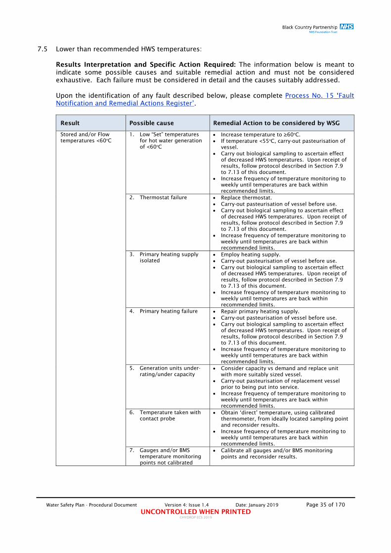
Water Safety Plan - Procedural Document Version 4: Issue 1.4 Date: January 2019 Page 35 of 170 UNCONTROLLED WHEN PRINTED
©HYDROP ECS 2019
7.5 Lower than recommended HWS temperatures:
Results Interpretation and Specific Action Required: The information below is meant to indicate some possible causes and suitable remedial action and must not be considered exhaustive. Each failure must be considered in detail and the causes suitably addressed. Upon the identification of any fault described below, please complete Process No. 15 ‘Fault Notification and Remedial Actions Register’.
Result Possible cause Remedial Action to be considered by WSG
Stored and/or Flow temperatures <60oC
1. Low “Set” temperatures for hot water generation of <60oC
Increase temperature to ≥60oC. If temperature <55oC, carry-out pasteurisation of
vessel. Carry out biological sampling to ascertain effect
of decreased HWS temperatures. Upon receipt of results, follow protocol described in Section 7.9 to 7.13 of this document.
Increase frequency of temperature monitoring to weekly until temperatures are back within recommended limits.
2. Thermostat failure Replace thermostat. Carry-out pasteurisation of vessel before use. Carry out biological sampling to ascertain effect
of decreased HWS temperatures. Upon receipt of results, follow protocol described in Section 7.9 to 7.13 of this document.
Increase frequency of temperature monitoring to weekly until temperatures are back within recommended limits.
3. Primary heating supply isolated
Employ heating supply. Carry-out pasteurisation of vessel before use. Carry out biological sampling to ascertain effect
of decreased HWS temperatures. Upon receipt of results, follow protocol described in Section 7.9 to 7.13 of this document.
Increase frequency of temperature monitoring to weekly until temperatures are back within recommended limits.
4. Primary heating failure Repair primary heating supply. Carry-out pasteurisation of vessel before use. Carry out biological sampling to ascertain effect
of decreased HWS temperatures. Upon receipt of results, follow protocol described in Section 7.9 to 7.13 of this document.
Increase frequency of temperature monitoring to weekly until temperatures are back within recommended limits.
5. Generation units under-rating/under capacity
Consider capacity vs demand and replace unit with more suitably sized vessel.
Carry-out pasteurisation of replacement vessel prior to being put into service.
Increase frequency of temperature monitoring to weekly until temperatures are back within recommended limits.
6. Temperature taken with contact probe
Obtain ‘direct’ temperature, using calibrated thermometer, from ideally located sampling point and reconsider results.
Increase frequency of temperature monitoring to weekly until temperatures are back within recommended limits.
7. Gauges and/or BMS temperature monitoring points not calibrated
Calibrate all gauges and/or BMS monitoring points and reconsider results.

Water Safety Plan - Procedural Document Version 4: Issue 1.4 Date: January 2019 Page 36 of 170 UNCONTROLLED WHEN PRINTED
©HYDROP ECS 2019
Return temperature <55oC when Flow temperature >60oC HWS Return at at the calorifiers and throughout the system including Primary, Secondary and Tertiary HWS return loops
1. Distribution system short circuiting
Carry out investigation of distribution pipe-work to locate possible short-circuit.
Increase frequency of temperature monitoring to weekly until temperatures are back within recommended limits.
2. Circulation pump under rated
Upgrade circulation pump to a suitable rating. Carry out biological sampling to ascertain effect
of decreased HWS temperatures. Upon receipt of results, follow protocol described in Section 7.9 to 7.13 of this document.
Increase frequency of temperature monitoring to weekly until temperatures are back within recommended limits.
3. Circulation pump faulty Replace/repair circulation pump. Increase frequency of temperature monitoring to
weekly until temperatures are back within recommended limits.
4. Temperature measurement taken down stream of cold supply
Re-measure temperature from location upstream of cold supply.
Increase frequency of temperature monitoring to weekly until temperatures are back within recommended limits.
5. Temperature taken with contact probe
Obtain ‘direct’ temperature, using calibrated thermometer, from ideally located sampling point and reconsider results.
Increase frequency of temperature monitoring to weekly until temperatures are back within recommended limits.
6. Gauges and/or BMS temperature monitoring points not calibrated
Calibrate all gauges and/or BMS monitoring points and reconsider results.
Distribution temperatures <55oC when Flow temperature >60oC
1. Excessive heat loss. Inspect HWS and CWS insulation and upgrade where practicable.
Carry out biological sampling to ascertain effect of decreased HWS temperatures. Upon receipt of results, follow protocol described in Section 7.9 to 7.13 of this document.
Increase frequency of temperature monitoring to weekly until temperatures are back within recommended limits.
2. “non-returned” pipe spurs
Inspect the length of non-returned spurs and rectify by relocating HWS Return to within 300mm of point of delivery if practicable.
Increase frequency of temperature monitoring to weekly until temperatures are back within recommended limits.
3. Areas of “low-flow” or dead-legs in the system
Increase water through-put by strategic flushing to reduce water retention time.
Carry out biological sampling to ascertain effect of decreased HWS temperatures. Upon receipt of results, follow protocol described in Section 7.9 to 7.13 of this document.
Increase frequency of temperature monitoring to weekly until temperatures are back within recommended limits.
4. Presence of space-heating apparatus on the HWS system
Investigate the presence of heat loss due the presence of space heating (towel rails, linen cupboard heaters, etc.) and remove from the system.
Carry out biological sampling to ascertain effect of decreased HWS temperatures. Upon receipt of results, follow protocol described in Section 7.9 to 7.13 of this document.
Increase frequency of temperature monitoring to weekly until temperatures are back within recommended limits.
5. Failure of Trace Heating system or Trace Heating system not extending to extremities of the
Inspect the Trace heating system and repair/replace if necessary or extend system to allow for temperature maintenance to system spurs.

Water Safety Plan - Procedural Document Version 4: Issue 1.4 Date: January 2019 Page 37 of 170 UNCONTROLLED WHEN PRINTED
©HYDROP ECS 2019
system. Carry out biological sampling to ascertain effect of decreased HWS temperatures. Upon receipt of results, follow protocol described in Section 7.9 to 7.13 of this document.
Increase frequency of temperature monitoring to weekly until temperatures are back within recommended limits.
*Strategic flushing comprises of the introduction of flushing of all identified infrequently used outlets and also of outlets which are suitably located on the system to enable the thorough and speedy purging of the HWS to allow for the reduction of water temperatures to within recommended limits. **Biological sampling must be carried out as described in Section 3.6 Bacterial contamination monitoring and in accordance with Process No. 1 'Microbiological sample collection protocol'. On receipt of biological analysis results, follow the procedures described in Section 7.9 to 7.13 of this document Result Interpretations and appropriate actions”. ***Persistently outside the recommended temperature limits: When cold domestic water system distribution temperatures are outside of the control limits on at least two consecutive temperature monitoring visits. NOTE: Ensure that all temperature measuring instruments including: thermometers; gauges and BMS Temperature monitoring points are adequately calibrated.

Water Safety Plan - Procedural Document Version 4: Issue 1.4 Date: January 2019 Page 38 of 170 UNCONTROLLED WHEN PRINTED
©HYDROP ECS 2019
7.6 Dead-legs and areas of infrequent use:
Results Interpretation and Specific Action Required: The information below is meant to indicate some possible causes and suitable remedial action and must not be considered exhaustive. Each failure must be considered in detail and the causes suitably addressed. Upon the identification of any fault described below, please complete Process No. 15 ‘Fault Notification and Remedial Actions Register’.
Result Remedial Action Notification of dead-legs 1. Remove dead-leg by cutting it back to the main distribution pipe-
work ensuring that ‘T’ piece is removed where practicable. 2. Carry out biological sampling to ascertain effect of the dead-leg.
Upon receipt of results, follow protocol described in Section 7.9 to 7.13 of this document.
Notification of Low and Infrequently Used outlets
1. Increase water through-put by the introduction of scheduled strategic flushing to reduce water retention time.
2. Consider the removal of the outlet. 3. Carry out biological sampling to ascertain effect of the dead-leg.
Upon receipt of results, follow protocol described in Section 7.9 to 7.13 of this document.
General 1. Ensure that all users are advised on the potential risks and appropriate actions required to prevent the likelihood of proliferation and exposure to Legionella bacteria in infrequently used/disused outlets.
2. Ensure that the users undertake flushing of all identified infrequently used outlets on a 2 x weekly basis as described in Process No. 9 'Dead Legs/Areas of Low Usage Evaluation and Flushing'
3. Where infrequently used facilities are deemed to be no longer required, they must be reported to the Responsible Person for removal.
**Biological sampling must be carried out as described in Section 3.6 Bacterial contamination monitoring and in accordance with Process No. 1 'Microbiological sample collection protocol'. On receipt of biological analysis results, follow the procedures described in Section 7.9 to 7.13 of this document Result Interpretations and appropriate actions”.

Water Safety Plan - Procedural Document Version 4: Issue 1.4 Date: January 2019 Page 39 of 170 UNCONTROLLED WHEN PRINTED
©HYDROP ECS 2019
7.7 Lower and/or higher than recommended Chlorine Dioxide levels:
Results Interpretation and Specific Action Required: The information below is meant to indicate some possible causes and suitable remedial action and must not be considered exhaustive. Each failure must be considered in detail and the causes suitably addressed. Upon the identification of any fault described below, please complete Process No. 15 ‘Fault Notification and Remedial Actions Register’.
Result Possible cause Remedial Action
<0.25ppm at dosing point
1. Chemical(s) levels depleted
Check chemical(s) levels and top-up if depleted. If lower than recommended levels persist for
more than three days, carry out biological sampling to ascertain effect of the lower than recommended levels. Upon receipt of results, follow protocol described in Section 7.9 to 7.13 of this document.
2. Dosing equipment malfunctioning
Check operating status of dosing equipment and contact service provider if found to be malfunctioning.
If lower than recommended levels persist for more than three days, carry out biological sampling to ascertain effect of the lower than recommended levels. Upon receipt of results, follow protocol described in Section 7.9 to 7.13 of this document.
>0.8ppm at dosing point
1. Dosing equipment malfunctioning
Isolate dosing equipment to disable further dosing of chemical. Note: This shall be done automatically by the use of real-time monitoring of the levels of disinfectant.
Check operating status of dosing equipment and contact service provider if found to be malfunctioning.
Purge the system thoroughly until chemical level falls to within the recommended limits.
Check random strainers/aerators for signs of significant biofilm contamination.
If higher than recommended levels persist for more than three days, carry out biological sampling to ascertain effect of the higher than recommended levels particularly to ascertain the potential of increased biofilm shearing. Upon receipt of results, follow protocol described in Section 7.9 to 7.13 of this document.
<0.1ppm at sentinel outlet
1. Chemical(s) levels depleted
Check chemical(s) levels and top-up if depleted. If lower than recommended levels persist for
more than three days, carry out biological sampling to ascertain effect of the lower than recommended levels. Upon receipt of results, follow protocol described in Section 7.9 to 7.13 of this document.
2. Dosing equipment malfunctioning
Check operating status of dosing equipment and contact service provider if found to be malfunctioning.
If lower than recommended levels persist for more than three days, carry out biological sampling to ascertain effect of the lower than recommended levels. Upon receipt of results, follow protocol described in Section 7.9 to 7.13 of this document.
3. Areas of “low-flow” or dead-legs in the system and lack of adequate use causing stagnation
Increase water through-put by strategic flushing to reduce water retention time.
If lower than recommended levels persist for more than three days, carry out biological sampling to ascertain effect of the lower than recommended levels. Upon receipt of results, follow protocol described in Section 7.9 to 7.13
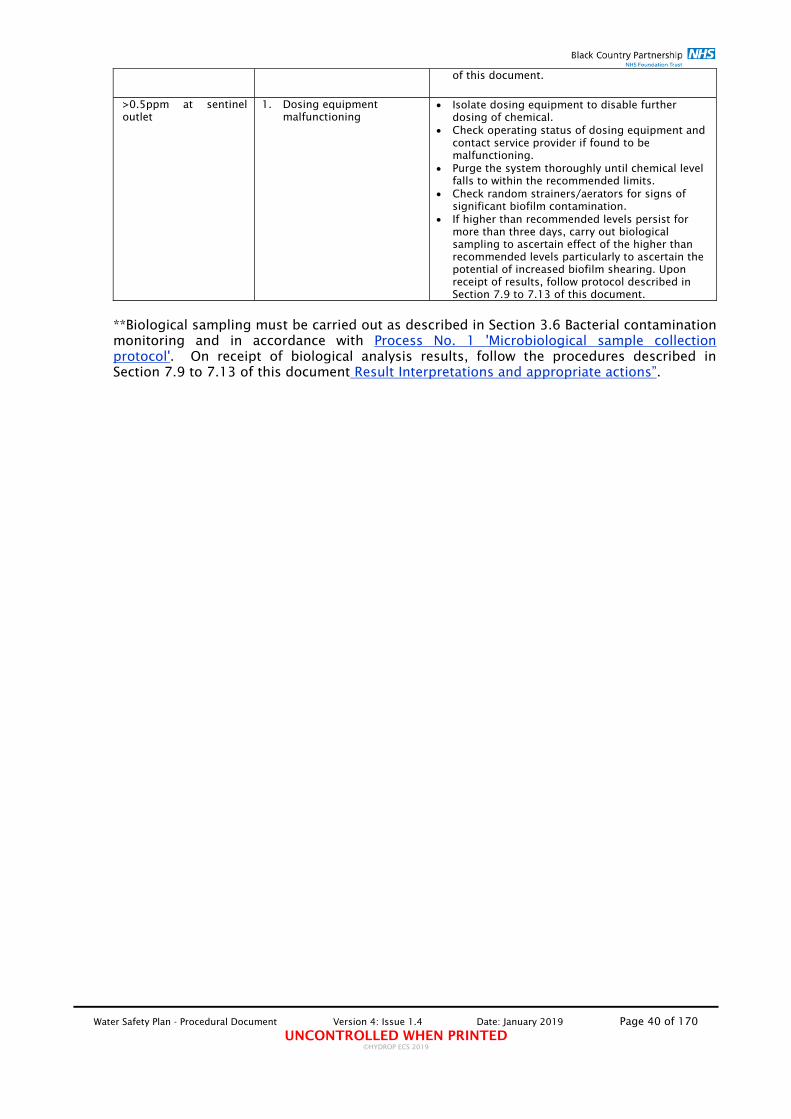
Water Safety Plan - Procedural Document Version 4: Issue 1.4 Date: January 2019 Page 40 of 170 UNCONTROLLED WHEN PRINTED
©HYDROP ECS 2019
of this document.
>0.5ppm at sentinel outlet
1. Dosing equipment malfunctioning
Isolate dosing equipment to disable further dosing of chemical.
Check operating status of dosing equipment and contact service provider if found to be malfunctioning.
Purge the system thoroughly until chemical level falls to within the recommended limits.
Check random strainers/aerators for signs of significant biofilm contamination.
If higher than recommended levels persist for more than three days, carry out biological sampling to ascertain effect of the higher than recommended levels particularly to ascertain the potential of increased biofilm shearing. Upon receipt of results, follow protocol described in Section 7.9 to 7.13 of this document.
**Biological sampling must be carried out as described in Section 3.6 Bacterial contamination monitoring and in accordance with Process No. 1 'Microbiological sample collection protocol'. On receipt of biological analysis results, follow the procedures described in Section 7.9 to 7.13 of this document Result Interpretations and appropriate actions”.

Water Safety Plan - Procedural Document Version 4: Issue 1.4 Date: January 2019 Page 41 of 170 UNCONTROLLED WHEN PRINTED
©HYDROP ECS 2019
7.8 Maintaining water supplies in an emergency: Results Interpretation and Specific Action Required: The information below is meant to indicate some possible causes and suitable remedial action and should not be considered exhaustive. Each failure must be considered in detail and the causes suitably addressed. Upon the identification of any fault described below, please complete Process No. 15 ‘Fault Notification and Remedial Actions Register’.
Result Remedial Action
Loss of primary water supply or where primary supply is contaminated chemically or microbiologically to unacceptable levels.
The Security and Emergency Measures (Water and Sewerage Undertakers) Direction 1998 is a statutory document produced under the provisions of Section 208 of the Water Industry Act 1991. Water suppliers have a duty arising from it to make and revise plans for the provision of essential water supply and wastewater services at all times. The Direction includes the duty for water suppliers to give priority to the domestic needs of the sick, older people, disabled people, hospitals, schools, and other vulnerable sectors of the population. Healthcare organisations should cooperate with water suppliers in developing plans to maintain essential supplies of water in the event of major incidents. These plans might include (see also HBN 00-07 – ‘Planning for a resilient healthcare estate’): The routine provision of public water supplies to the site from more
than one water main, preferably using mains that are fed from different water supply zones. Where mains are fed from different zones, particular care should be taken within the site to prevent direct interconnection and backflow between plumbing systems fed from the different supply zones.
Note: any arrangements designed-in should ensure there are no areas where water can stagnate (for example, dead-legs). Adequate storage cistern capacity and distribution arrangements
within the healthcare facility to provide minimum volumes of water at the outset of a major incident to maintain hygiene and health for an initial period until other temporary arrangements can be introduced.
The provision of facilities to connect to, and distribute water from, temporary storage cisterns such as pillow tanks at key locations within the site. Ground-level storage cisterns will require provision of booster pumps to either lift the water to existing storage cisterns or to distribute it directly through existing or temporary-site water mains.
The provision of connection points to existing storage cisterns at suitable locations for delivery of emergency supplies of water, for example from tankers.
Suitable distribution points for bottled water should be considered in the design process. This should work in conjunction with plans for the supply and distribution of bottled water for drinking to vulnerable patients and those unable to collect supplies from distribution points within the healthcare facility.
Note: The Trust, or others on its behalf, when providing and managing temporary water supplies, shall comply with their duties under the Health and Safety at Work etc. Act a and BS 8551:2015 ‐ Provision and management of temporary water supplies (not including provisions for statutory emergencies). This provides clear practical guidance on how to install temporary supplies, whether by connection to the mains or tanker‐fed, and how the distribution system should be disinfected and tested to ensure that the water is wholesome. It also considers the safe storage of bottled water, though not the maintenance of the dispensers.

Water Safety Plan - Procedural Document Version 4: Issue 1.4 Date: January 2019 Page 42 of 170 UNCONTROLLED WHEN PRINTED
©HYDROP ECS 2019
7.9 Results Reporting and Actions Flow Chart:
AE(W) Audit Report
Samples collected
Samples delivered to the appropriate laboratory within specified dead‐line
Positive Results reported
Non‐detected results reported
DEFECT‐LOG
Electronic Log‐Book
KPI analysis and dash‐
board report preparation by Estates
WSG
KPI analysis and dash‐
board report review by IPC
Actions requested
IPC consider results and
implement risk mitigation processes
Complete 'Fault Notification and Remedial Actions Register'
Complete 'Adverse Water Sample Results Reporting and
Remedial Actions Register'
Monthly Estates Management
Review
3 ‐ MONTHLY AE(W) AUDIT
Remedial works
required
Complete Contamination Risk Assessment'
Final Results Positive
Presumptive Results
Negative Presumptive Results
Follow actions detailed in 'Adverse Water Sample Results pro‐forma and
described in Section 7.9 – 7.12
Adverse results memo issued to Estates/IPC
Re‐sample collection requested

Water Safety Plan - Procedural Document Version 4: Issue 1.4 Date: January 2019 Page 43 of 170 UNCONTROLLED WHEN PRINTED
©HYDROP ECS 2019
7.10 Water microbiological water analysis sample results interpretation:
Analysis Sample Reported Results Result Interpretation
Legionella sp.
None Detected Negative
<100cfu/l Insignificant
>100cfu/l - <1,000cfu/l Significant
>1,000cfu/l Highly Significant
Coliforms and E. coli
None Detected Negative
<1cfu/100ml Negative
>1cfu/100ml Highly Significant
Aerobic count TVCC
None Detected Negative
>10cfu/ml - <100cfu/ml Insignificant
>100cfu/ml - <1,000cfu/ml Significant
>1,000cfu/ml Highly Significant

Water Safety Plan - Procedural Document Version 4: Issue 1.4 Date: January 2019 Page 44 of 170 UNCONTROLLED WHEN PRINTED
©HYDROP ECS 2019
7.11 Follow-up processes for Legionella 'failures' re-samples:
Legionella 'Failure' Results Received
'Adverse Water Samples Results and Remedial Actions Register' completed by the Responsible Person (Estates) or IPC. The results of this process must be considered by: Estates; Departmental Head; Trust CM and DIPC for any additional comments/remedial works required. In
addition to the completion of the local risk assessment’ shall be carried out, by completing the Contamination Risk Assessment
Failure
At least 48hrs following remedial works
Collect pre- and post-flush sample and submit for analysis
Pass
Failure
One week following last re-sample
Collect pre- and post-flush sample and submit for analysis
Pass
Failure
Two weeks following last re-sample
Collect pre- and post-flush sample and submit for analysis
Pass
Outlet considered 'clear'
Remove all contingency measures

Water Safety Plan - Procedural Document Version 4: Issue 1.4 Date: January 2019 Page 45 of 170 UNCONTROLLED WHEN PRINTED
©HYDROP ECS 2019
7.12 Microbiological analysis results - Plant:
The information below is meant to indicate some possible causes of the reported contamination and suitable remedial action and must not be considered exhaustive or prescriptive. Each failure must be considered in detail and the causes suitably addressed. It is important, therefore, that all identified bacterial contamination, irrespective of species, serogroup, level of contamination and whether isolated from a pre‐ or post‐flush sample must be closely considered as a more bespoke approach to risk management maybe needed. In addition, a ‘local risk assessment’ shall be carried out, by completing the Contamination Risk Assessment, found in Appendix 1. The Risk Assessment shall consider the maintenance records for the area and also investigate the water systems in the area to identify the underlying cause of the problems and set out the remedial action necessary to address the threat. A Local Risk Assessment is a team exercise that requires the input from the appropriate members of the WSG. The outcomes of Local Risk Assessments shall be considered by the WSG to identify any "Lessons Learned" from the incident.
PARAMETERS PRE-FLUSH SAMPLE RESULT
Result Plant Remedial Action
Negative
Cold Water Storage Tanks
Incoming Supply No action required.
Stored Water No action required.
Drain No action required.
Storage Calorifiers Drain No action required.
Insignificant
Cold Water Storage Tanks
Incoming Supply
Thoroughly flush Incoming Supply and re‐sample.
If repeat positive result, obtain samples at different locations of the same supply, upstream of the tank to determine the extent of contamination results and action accordingly where required.
Consider the disinfection of the supply run to the tank if found to be contaminated further up‐stream of the tank (if practicable).
Ensure that the tank is adequately used and is not over capacitated. Reduce capacity or/and increase flow‐through if found to be over capacitated.
Review Management & Control Programme to ensure adequate and correct implementation and within recommended parameters.
Stored Water
Consider the Incoming Supply results (above) and action accordingly where required.
If Incoming Supply result is negative, empty tank and re fill and re‐sample.
Ensure that the tank is adequately used and is not over capacitated. Reduce capacity or/and increase flow‐through if found to be over capacitated.
Check ambient temperature and ambient ventilation.
Ensure that the tank is adequately insulated.
Review Management & Control Programme to ensure adequate and correct implementation.
Drain
If the Stored Water result is negative, thoroughly flush drain and resample.
Consider length of drain to isolation valve and if practicable, reduce to ≤300mm or 3 x Ǿ.
If the Stored Water sample is positive, action accordingly (see above).
Ensure that the tank is adequately used and is not over capacitated. Reduce capacity or/and increase flow‐through if found to be over capacitated.
Review Management & Control Programme to ensure adequate and correct implementation and within recommended parameters.
Storage Calorifiers Drain
Thoroughly flush drain.
If repeat and persistent positive result, thoroughly flush drain and carry out a calorifier pasteurisation.
Re‐sample at least 48hrs after the disinfection. The calorifier can be put back into use. When the sample results received, action accordingly as described in this Section.
Consider length of drain to isolation valve and if practicable, reduce to ≤300mm or 3 x Ǿ.
Review Management & Control Programme to ensure adequate and correct implementation and within recommended parameters.
Significant
Cold Water Storage Tanks
Incoming Supply
Thoroughly flush incoming supply and resample. Obtain samples at different locations of the same supply, upstream of the tank to determine the extent of contamination results and action accordingly where required.
Consider the disinfection of the supply run to the tank if found to be contaminated further up‐stream of the tank (if practicable). If supply is disinfected, re‐sample at least 48hrs after the disinfection. When the sample received, action accordingly as described in this Section.
Consider the supply/valve configuration of this and any associated tanks to ensure that no deadleags are present due to the status of the valves. Where supply/valve configuration is considered to contribute to the potential of contamination, carry out any necessary remedial works to address such concerns.
Ensure that the tank is adequately used and is not over capacitated. Reduce capacity or/and increase flow‐through if found to be over capacitated.
Review Management & Control Programme to ensure adequate and correct implementation and within recommended parameters.
Stored Water
Consider the Incoming Supply results and action accordingly where required. Ensure that any contamination associated with the Incoming Supply is removed before carrying out tank clean and disinfection.
Drain tank, clean and disinfect.
Re‐sample at least 48hrs after the disinfection. The Tank can be put back into use. When the sample received, action accordingly as described in this Section.
Ensure that the tank is adequately used and is not over capacitated. Reduce capacity or/and increase flow‐through if found to be over capacitated.
Review Management & Control Programme to ensure adequate and correct implementation and within recommended parameters.
Drain
If the Stored Water result is negative, thoroughly flush drain and resample.
Consider length of drain to isolation valve and if practicable, reduce to ≤300mm or 3 x Ǿ.
If the Stored Water sample is positive, action accordingly (see above).
Ensure that the tank is adequately used and is not over capacitated. Reduce capacity or/and increase flow‐through if found to be over capacitated.
Review Management & Control Programme to ensure adequate and correct implementation and within recommended parameters.
Storage Calorifiers Drain
Thoroughly flush drain and carry out a calorifier pasteurisation.
Re‐sample at least 48hrs after the disinfection. The calorifier can be put back into use. When the sample results received, action accordingly as described in this Section.
If the resample is positive, collect a sample of the cold supply to the calorifier, where practicable, and depending on the results, action accordingly.
Consider length of drain to isolation valve and if practicable, reduce to ≤300mm or 3 x Ǿ.
Check for temperature stratification and rectify.
Review Management & Control Programme to ensure adequate and correct implementation and within recommended parameters.
Highly Significant
Cold Water Storage Tanks
Incoming Supply
Isolate supply.
Provide an alternative, clean, supply where practicable.
Carry out disinfection of the supply run to the tank and re‐sample at least 48hrs after the disinfection. When the resample received, action accordingly as described in this Section. Only allow supply back into use when negative resample result is obtained.
Consider the supply/valve configuration of this and any associated tanks to ensure that no deadleags are present due to the status of the valves. Where supply/valve configuration is considered to contribute to the potential of contamination, carry out any necessary remedial works to address such concerns.
Ensure that the tank is adequately used and is not over capacitated. Reduce capacity or/and increase flow‐through if found to be over capacitated.
Review Management & Control Programme to ensure adequate and correct implementation and within recommended parameters.
Stored Water
Take Tank out of use.
Consider the Incoming Supply results and action accordingly where required. Ensure that any contamination associated with the Incoming Supply is removed before carrying out tank clean and disinfection.
Drain tank, clean and disinfect.
Re‐sample at least 48hrs after the disinfection.
The Tank must remain out of use, but flushed via the drain where practicable, until negative resample results are received.
Ensure that the tank is adequately used and is not over capacitated. Reduce capacity or/and increase flow‐through if found to be over capacitated.
Review Management & Control Programme to ensure adequate and correct implementation and within recommended parameters.
Drain
If the Stored Water result is negative, thoroughly flush drain and resample.
Consider length of drain to isolation valve and if practicable, reduce to ≤300mm or 3 x Ǿ.
If the Stored Water sample is positive, action accordingly (see above).
Ensure that the tank is adequately used and is not over capacitated. Reduce capacity or/and increase flow‐through if found to be over capacitated.
Review Management & Control Programme to ensure adequate and correct implementation and within recommended parameters.
Storage Calorifiers Drain
Take Calorifier out of use.
Thoroughly flush drain and carry out a calorifier pasteurisation.
Re‐sample at least 48hrs after the disinfection and wait for the results before allowing the Calorifier back into use.
If the resample is positive, collect a sample of the cold supply to the calorifier, where practicable, and depending on the results, action accordingly.
Consider length of drain to isolation valve and if practicable, reduce to ≤300mm or 3 x Ǿ.
Check for temperature stratification and rectify.
Review Management & Control Programme to ensure adequate and correct implementation and within recommended parameters.

Water Safety Plan - Procedural Document Version 4: Issue 1.4 Date: January 2019 Page 46 of 170 UNCONTROLLED WHEN PRINTED
©HYDROP ECS 2019
7.13 Legionella Microbiological analysis results:
The information below is meant to indicate some possible causes of the reported contamination and suitable remedial action and must not be considered exhaustive or prescriptive. Each failure must be considered in detail and the causes suitably addressed. It is important, therefore, that all identified Legionella contamination, irrespective of species, serogroup, level of contamination and whether isolated from a pre‐ or post‐flush sample must be notified to IPC immediately upon receipt of sample results as a more bespoke approach to risk management maybe needed. In addition, a ‘local risk assessment’ shall be carried out, by completing the Contamination Risk Assessment. The Risk Assessment shall consider the maintenance records for the area, domestic cleaning records, flushing records and also investigate the water systems in the area to identify the underlying cause of the problems and set out the remedial action necessary to address the threat. As part of the local risk assessment, an assessment of the patients shall be carried out so that appropriate measures are taken to protect any patients that may be considered to be susceptible to infection. A Local Risk Assessment is a team exercise that requires the input from the appropriate members of the WSG. The outcomes of Local Risk Assessments shall be considered by the WSG to identify any "Lessons Learned" from the incident.
SAMPLE RESULT
Sample Result
PRE-FLUSH SAMPLES POST-FLUSH SAMPLES
Interpretation Remedial Action Interpretation Remedial Action
Negative N/A No action required. Consider the Post-flush results and action accordingly where
required. N/A
No action required. Consider the Pre-flush results and action accordingly where required.
Insignificant
Insignificant levels of localised contamination only, if in the absence of positive post flush sample results.
Flush outlet and review ‘Usage Evaluation and Flushing’ records and action accordingly.
Clean and disinfect all aerators and flow straighteners. Renew where required. Consider their permanent removal.
No re-sample required. Put outlet back in-use. Consider the Post-flush results and action accordingly where
required. Review Management & Control Programme to ensure adequate
and correct implementation. IPC to provide advice on the requirement to re-sample and
installation of POU filters in high risk patient areas (where practicable).
Insignificant levels of systemic contamination, if in the presence of other post flush positive sample results.
If found in the absence of others (in the majority) post flush +ves; clean and disinfect all aerators and flow straighteners associated with outlets which return +ves. Renew where required. Consider their permanent removal.
No re-sample required. Put outlet back in-use. If found in the presence of other (in the majority) post-flush +ves, carry out
remedial action as described above and thoroughly and repeatedly flush the whole system and carry out Re-sample. If this is a repeat +ve result, widen the sample locations schedule to ascertain extent of contamination.
On the advice of IPC and Engineering; consider system disinfection and re-sample, no earlier than 48 hrs after the disinfection process.
IPC to provide advice on the requirement to re-sample and, where possible, to install POU filter and put outlet back in-use whilst awaiting re-sample results. Where the installation of POU filter is not possible, keep outlet out-of-use but continue to flush on a daily basis whilst awaiting for the results.
Review Management & Control Programme to ensure adequate and correct implementation.
Significant/ Moderately Significant
Significant levels of localised contamination only if in the absence of positive post flush sample results.
Risk assess potential harm to users Where practicable and applicable, clean and disinfect outlet,
associated aerators and flow straighteners and TMV strainers. Renew where required. Consider their permanent removal.
Flush outlet and review ‘Usage Evaluation and Flushing’ records and action accordingly
Consider the Post-flush Carry out Re-sample no earlier than 48 hrs after the clean and disinfection. If this is a repeat +ve result, widen the sample locations schedule to ascertain extent of contamination results and action accordingly where required.
Where possible, install POU filter and put outlet back in-use whilst waiting re-sample results. Where the installation of POU filter is not possible, keep outlet out-of-use but continue to flush on a daily basis whilst waiting for the results.
Review Management & Control Programme to ensure adequate and correct implementation.
Reinstate outlet and/or remove POU only upon receipt of three consecutive negative result (see flow-chart Section 7.11).
Significant levels of systemic contamination, if in the presence of other post flush positive sample results.
Risk assess potential harm to users If found in the absence of others (in the majority) post flush +ves; clean
and disinfect all aerators and flow straighteners. Renew where required. Consider their permanent removal.
Carry out Re-sample, no earlier than 48 hrs after the clean and disinfection. If this is a repeat +ve result, widen the sample locations schedule to ascertain extent of contamination.
If found in the presence of other (in the majority) post-flush +ves, carry out remedial action as described above and carry-out system (including all source units) disinfection and re-sample (including from the incoming mains and all source units,, no earlier than 48 hrs after the disinfection process. If this is a repeat +ve result, widen the sample locations schedule to ascertain extent of contamination.
IPC to provide advice on the requirement to install of POU filters in high risk patient areas, of if the installation of POU filters is not possible keep outlet out of use and flush daily, whilst waiting for the results of the re-samples.
Review Management & Control Programme to ensure adequate and correct implementation.
If persistent post-flush +ves, consider the installation of an on-line disinfection system capable of controlling bacterial contamination independent to temperature control requirements.
Reinstate outlet and/or remove POU only upon receipt of three consecutive negative result (see flow-chart Section 7.11).
Highly Significant
Highly Significant levels of localised contamination only if in the absence of positive post flush sample results.
Risk assess potential harm to users Take outlet out of use immediately if required. Where practicable and applicable, clean and disinfect outlet,
associated aerators and flow straighteners and TMV strainers. Renew where required. Consider their permanent removal.
Flush outlet and review ‘Usage Evaluation and Flushing’ records and action accordingly.
Consider the Post-flush results and action accordingly where required.
Carry out Re-sample no earlier than 48 hrs after the clean and disinfection. If this is a repeat +ve result, widen the sample locations schedule to ascertain extent of contamination.
Where possible, install POU filter and put outlet back in-use whilst waiting re-sample results. Where the installation of POU filter is not possible, keep outlet out-of-use but continue to flush on a daily basis whilst waiting for the results.
On the advice of IPC, continue to keep outlet out-of-use until –ve results received from re-sample results in high risk patient areas.
Review Management & Control Programme to ensure adequate and correct implementation.
Reinstate outlet and/or remove POU only upon receipt of three consecutive negative result (see flow-chart Section 7.11).
Highly significant levels of systemic contamination, if in the presence of other post flush positive sample results.
Risk assess potential harm to users Take outlet out of use immediately if required. If found in the absence of others (in the majority) post flush +ves; clean
and disinfect all aerators and flow straighteners. Renew where required. Consider their permanent removal.
Carry out Re-sample no earlier than 48 hrs after the clean and disinfection. If this is a repeat +ve result, widen the sample locations schedule to ascertain extent of contamination.
If found in the presence of other (in the majority) post-flush +ves, carry out remedial action as described above and carry-out system (including all source units) disinfection and re-sample (including from the incoming mains and all source units,, no earlier than 48 hrs after the disinfection process. If this is a repeat +ve result, widen the sample locations schedule to ascertain extent of contamination.
In all high risk areas and on the advice of IPC, continue to keep system out-of-use until –ve results received from re-sample results in high risk patient areas, or, again on the advice of IPC and where practicable, install POU filters to allow continued use of the system whilst awaiting for sample results.
Review Management & Control Programme to ensure adequate and correct implementation.
If persistent post-flush +ves, consider the installation of an on-line disinfection system capable of controlling bacterial contamination independent to temperature control requirements.
Reinstate outlet and/or remove POU only upon receipt of three consecutive negative result (see flow-chart Section 7.11).

Water Safety Plan - Procedural Document Version 4: Issue 1.4 Date: January 2019 Page 47 of 170 UNCONTROLLED WHEN PRINTED
©HYDROP ECS 2019
8. WATER SYSTEM/PLANT DESIGN INSTALLATION COMMISSIONING AND MAINTENANCE Management of water systems and associated end-of-line fittings to reduce the risk of microbial growth including opportunistic pathogens such as Legionella sp. is vital to patient safety. It requires on-going maintenance and surveillance of control measures employed. The plant and equipment used in Trust buildings which have water in the system and can affect the water supply or the atmosphere must be monitored regularly and be subjected to the following regime: i. The systems must be carefully designed so as to minimise aerosols and the material
used in construction would not harbour or provide nutrient for bacteria. They must be designed to be readily drained and cleaned.
ii. The systems must be maintained in a clean and sound condition and must be easily and safely accessible.
iii. All plant and distribution pipe-work (where accessible) must be clearly labelled. iv. The water quality must be maintained by ensuring the systems are kept in a good
condition or by either regular cleaning and disinfecting on a regular dosage of water treatment.
v. Careful monitoring of the precautions. vi. Records must be kept of the maintenance performed and the results obtained. The Trust is required to identify, remove and manage potential ligature risks in order to prevent suicides within in-patients settings. It is important therefore to ensure that all fixtures and fittings pertaining to the design installation and commissioning of domestic and process water systems comply with the anti-ligature risk assessment for the area concerned.
8.1 Supplies from a water undertaker: The following factors must be taken into consideration in the initial stages of the design: i. The water undertaker’s requirements. ii. The estimated daily consumption and the maximum and average flows required,
together with the estimated time of peak flow. iii. The location of the available supply. iv. The quality, quantity and pressure required. v. The cold water storage capacity required. vi. The likelihood of ground subsidence due to mining activities or any other reason. vii. The likelihood of there being any contaminated land on site. viii. The proposed method of storage and probable number and purpose of direct
connections to pressure mains. ix. The minimum and maximum pressures available at the service connection. x. Details of the physical, chemical and microbiological characteristics of the water supply
and scope of any possible variations in such characteristics. xi. The possibility of an alternative service connection from some other part of the water
undertaker’s network, including pressure details.
8.2 Primary Water Supplies: Water supplied for such domestic purposes as consist in or include, cooking, drinking, food preparation or washing shall be regarded as wholesome as it applies to the supply of water for those domestic purposes, if the following requirements are satisfied: i. That the water does not contain any micro-organism or parasite; or any substance at a
concentration or value which would constitute a potential danger to human health – See ‘The Water Supply (Water Quality) Regulations 2000 and The Water Supply (Water

Water Safety Plan - Procedural Document Version 4: Issue 1.4 Date: January 2019 Page 48 of 170 UNCONTROLLED WHEN PRINTED
©HYDROP ECS 2019
Quality) (Amendment) Regulations 2011’ and the Trust’s ‘Biological Contamination Measured Parameters’.
ii. That the water does not contain any substance at a concentration or value which, in conjunction with any other substance it contains would constitute a potential danger to human health.
Guidance Note 5: No connection to any part of the hospital’s Primary water supply shall be made without the written authorisation of the Responsible Person (Estates).
8.3 Water Treatment Requirements:
i. All water supplied to hospital must comply with current legislation on water quality. ii. The need for water treatment, and the treatment processes used shall depend on the
purposes for which the water is to be used and the quantity required for each purpose. iii. Where continuous water treatment is installed, the commissioning records must
include details of settings of the equipment, dosing rates and requirements for testing. iv. Levels of disinfectant shall be agreed with the Project Manager prior to commissioning
the plant and equipment. v. To prevent the accumulation of biofilm during construction and testing, continuous
dosing of water systems with appropriate biocides, such as chlorine dioxide, must be considered. Such treated systems must be regularly flushed to ensure that the biocide reaches all parts of the systems, and particularly outlets. Dosing with an appropriate level of biocide as soon as water hits a pipe or storage vessel (when system is first subjected to pressure testing), along with regular flushing, can control the accumulation of biofilm more effectively.
8.4 General Design and Installation Considerations:
Domestic water systems and associated equipment which utilise water and can affect the water supply, the atmosphere and the user, shall be properly designed, installed, commissioned, monitored regularly and be subjected to the following regimen: i. All designs must be in accordance with all relevant and current Guidelines, British
Standards, 'best-practices', Health Technical Memoranda, Health Guidance Notes and National Health Service Model engineering specifications.
ii. The systems shall be carefully designed to, where practicable, eliminate or minimise aerosol production and excessive water retention. They must also be designed to be readily drained, cleaned, and where necessary, suitably disinfected.
iii. No materials used in construction shall include those that are known to harbour or provide nutrient for bacteria. Plastic pipe-work shall be avoided wherever practicable and copper shall be used wherever possible. Any materials that come into contact with the water shall comply with the requirements of the Water Supply (Water Fittings) Regulations 1999. The list of products and materials that have been assessed for compliance with the Water Supply (Water Fittings) Regulations 1999 requirements are listed on the WRAS website – www.wras.co.uk. Further information on the selection of materials can be found in BS 8558:2015, BS6920 and HTM 04-01.
iv. All TMVs and TMTs installed must be compliant with the National Health Service Model Engineering Specifications D08 - Thermostatic mixing valves (Healthcare Premises) and the TMV3 Approved Scheme and installed in accordance with all relevant and current Guidelines, British Standards, 'best-practices', Health Technical Memoranda, Health Guidance Notes and National Health Service Model engineering specifications. The list of currently approved TMVs and TMTs is to be found on the WRAS website – www.wras.co.uk.
v. The systems shall be maintained in a clean and sound condition and must be easily and safely accessible.
vi. All systems shall be frequently used (at least 2 x weekly throughout), or suitably flushed to simulate the necessary usage frequency, in order to avoid stagnant water which will increase the potential of bacterial growth and proliferation. The 'users' of facilities shall undertake Weekly evaluations of usage frequency and implement

Water Safety Plan - Procedural Document Version 4: Issue 1.4 Date: January 2019 Page 49 of 170 UNCONTROLLED WHEN PRINTED
©HYDROP ECS 2019
suitable and sufficient control measures so that that the correct actions are regularly monitored and reported upon.
vii. As far as reasonably practicable, no flexible hoses shall be fitted to any new buildings or refurbishments commissioned by or on behalf of Trust since some flexible hoses are unsuitable for use in domestic water, because they support microbial growth, give the water a very strong, unpleasant, taste and odour or release toxic substances into it. Hose materials may encourage the growth of Legionella bacteria. Flexible hoses are typically steel braided with a synthetic rubber inner lining such as EPDM (ethylene propylene diene monomer). Several reports indicate that high levels of Pseudomonas and Legionella bacteria have been found in water samples taken from water outlets fed by flexible hoses, confirmed by testing of the hoses. These revealed colonisation of the lining. The lining of the material in these reports was EPDM. However, it is possible that other lining materials (and washers within the couplings) could be similarly affected. New lining materials such as PE (polyethylene), PEX (cross-linked polyethylene), LLDPE (linear low-density polyethylene) and PVC C (post-chlorinated PVC) are now on the market and others are likely to follow. However, their long-term performance regarding the growth of microorganisms is still unknown. Changes in this situation may be reflected in future guidance. Flexible hoses used in potable water supply systems shall be identified and risk assessed for the possibility of contamination with harmful microorganisms. An action plan shall be developed, which gives priority to areas of highest risk (i.e. those with persons vulnerable to infection). Depending on the risk assessment, the action plan shall address replacement of flexible hoses with hard or soft bendable metal or plastic pipes. Where flexible hoses must be used (e.g. on essential equipment such as hi-low baths) they must be constructed from a suitable alternative to EPDM, such as PEX, as well as being Water Regulations Advisory Scheme (WRAS) approved. Care must be taken to avoid kinking or distorting them during installation.
viii. In new and existing premises, it is essential that the needs of individual patient washing and bathing requirements are carefully considered. In new premises, the provision, correct siting and installation of showers and wash-hand basins, particularly in accommodation where patients are unlikely to make use of them, requires assessment. For existing premises, and subject to a risk assessment, permanent removal of disused or infrequently used outlets and their associated pipework must be considered.
ix. Tap design has evolved. In older installations, thermostatic control of water temperature was achieved by a separate thermostatic mixing valve (TMV) (commonly called a "t-shaped" TMV), typically located behind the sanitary assembly panel to which a wash-hand basin or other assembly was fitted, which then supplied water to the hot connection of a manual mixing tap or separate tap. Many new installations now include thermostatically controlled thermostatic mixing taps which are usually manually controlled (on and off) and can be adjusted to further reduce outlet temperature to fully cold. For some applications, remote sensor-operated taps are available (many sensor taps also have the option of auto-flushing programmes and can be linked to the hospital’s building management system). In some instances, these developments have led to a more complicated internal tap design which may increase the need for additional routine maintenance.
x. The choice and type of water outlets must be based on a risk assessment of infection-control and scalding issues.
xii. There is some evidence that the more complex the design of the outlet assembly (for example, some sensor-operated taps), the more prone to bacterial colonisation the outlet may be.
xiii. All plant and distribution pipe-work (where accessible) shall be clearly labelled and adequately insulated.
8.5 Cold Water Storage:
i. Cold water storage tanks shall be constructed from non-deleterious materials which must be WRAS approved.

Water Safety Plan - Procedural Document Version 4: Issue 1.4 Date: January 2019 Page 50 of 170 UNCONTROLLED WHEN PRINTED
©HYDROP ECS 2019
ii. Cold water storage tanks shall be designed and installed in accordance with the current Water Supply (Water Fittings) Regulations 1999, installed in appropriate and suitable locations to allow easy and safe access to facilitate inspection and maintenance.
iii. Sectional Cold Water Storage tanks shall be designed with external assembly flanges and self-draining profiles, since this arrangement facilitates easy cleaning of internal surfaces.
iv. Externally located Cold water storage tanks shall be suitably protected from environmental conditions, particularly the local high ambient temperatures for all new buildings and, where practicable, for existing installations.
v. Cold water storage tanks shall be protected from the ingress of light, insects and birds.
vi. Cold water storage tanks shall be sized and arranged so as to minimise retention time of stored water (24hrs maximum), and therefore to increase the rate of stored water exchange.
vii. Cold water storage tanks shall be subjected to a periodic “need” test which requires the user to question the presence of each unit and consider its removal if the services it supplies can be, equally well, supplied by converting the systems to domestic Mains fed only.
viii. Each unit shall be subjected to an annual “drop-test” designed to ascertain the capacity and demand requirements of each system, in order to ensure that excessive volumes of water are not unnecessarily stored. Eliminating storage within a system would also allow the negation of the necessary PPM Programme tasks and their replacement with much less onerous, more infrequent and less costly tasks to be carried out.
ix. All associated pipework and valves shall be adequately insulated and clearly labelled to identify their purpose.
x. The use of delayed-action ball valves shall be fitted (where practicable) in order to help avoid stagnation of water.
xi. Where Cold water storage tanks are linked “in parallel”, each feed to each tank shall be fitted, where practicable, with a water meter in order to allow for confirmation of equal and uniform usage from all tanks in the configuration.
xii. Various arrangements of pumping systems are indicated in BS 8558:2011. Where booster pumps are to be installed, a break cistern will be required between the mains supply pipe and the pumps. This is required in order to comply with the Water Supply (Water Fittings) Regulations 1999 with regard to prevention of backflow. Control of the pump(s) must be fully automatic in operation and controlled by pressure sensors. Where two or more pumps are installed, the design flow must be achieved with one pump stationary (or out of service). Automatic control must be provided to cyclically and sequentially control all pumps to ensure that each is regularly brought into service.
xiii. Cold water storage tanks shall be maintained in good condition, clean from excessive corrosion, sludge deposition, scale deposition.
xiv. Stored water shall be maintained at a temperature of <20oC (or <2oC from the supply). xv. Where indicated and when it is deemed necessary and practicable, Cold Water Storage
Tanks shall be upgraded, refurbished, modified or replaced so that they may comply with current Water Supply (Water Fittings) Regulations 1999. Following these works, each tank shall be cleaned and disinfected in accordance with BS 8558:2011 and L8 prior to it being allowed back into service.
xvi. Cold Water Storage Tanks shall be subjected to periodic monitoring to include: 1. Temperature monitoring: a. Continuously by a suitably calibrated BMS system where installed. b. When more than one CWS direct-supplied outlet, supplied by the tank, is found to
be >20oC during the monthly sentinel outlet temperature monitoring task. c. Annually carry-out a 24hr temperature profile under “normal operating
conditions”, where a BMS system is not installed 2. Regular general physical inspections the frequency of which shall depend on
current PPM Programme or risk assessment, where different. xvii. Cold Water Storage Tanks must not be subjected to unnecessary, anniversary-based
Water Safety Plan - Procedural Document Version 4: Issue 1.4 Date: January 2019 Page 51 of 170 UNCONTROLLED WHEN PRINTED
©HYDROP ECS 2019
clean and disinfections. Instead, they shall be subjected to a clean and disinfection, when the results of the monitoring indicate the need. Please refer to Section 7 - Engineering Contingency Measures for further information.
8.6 Hot Water generation and storage:
i. Hot water generation and storage units shall be installed in appropriate and suitable
locations to allow easy and safe access to facilitate inspection and maintenance. ii. Where more than one hot water generation unit is used, they shall be connected in
parallel, taking care to ensure that the flow can be balanced so that the water temperature from all the units exceeds 60°C at all times.
iii. The combined storage capacity and heater output must be sufficient to ensure that the outflow temperature, at continuous design flow (at least 20 minutes) from calorifiers or other heaters, must not be less than 60°C. This applies to both circulating and non-circulating hot water systems.
iv. Plate heat exchanges shall, where practicable, be installed without buffers vessels. Where buffer vessels are used, they shall not receive the CWS feed directly. All buffer vessels fitted, shall be subjected to a regular temperature monitoring programme and contents maintained at ≥60.0oC.
v. The positioning of the control and high limit thermostats, cold feed and return water connections must ensure that these temperatures are achieved.
vi. Means must be taken to prevent warm water entering the cold-feed. A check valve shall be provided in the cold feed, as close to the unit as practicable, to prevent such circulation. However, the installation of such a check valve shall not be carried out in systems that use the cold feed for expansion. In these cases, the installation of a U-bend or S-bend in the cold-feed, sufficient distance from the connection to the unit, so that water which is warm is not displaced (on heating up) beyond the bend and the vertical pipe rise shall be carried out.
vii. The practice of terminating the air vent over the Water Storage Tank shall be discouraged. The vent must be arranged to discharge over a separate tun-dish arrangement, with a visible Type A air gap, sited at a level that takes account of the hydrostatic head of the system. The calorifier or water heater must be provided with a suitable safety valve of appropriate size and vacuum release arrangement.
viii. Where water quality indicates the need, cathodic protection from galvanic action by means of sacrificial anodes shall be provided.
ix. Calorifiers and buffer vessels (where necessary) shall be fitted with a de-stratification pump, where necessary, in order to avoid temperature stratification of the stored water. Some semi-storage/high-efficiency calorifiers are supplied with an integral pump that circulates water in the calorifier. De-stratification pumps shall not be fitted to this type of units.
x. A single circulating pump shall normally be installed in the return. If, for reasons of reliability, two pumps are installed in parallel they shall be arranged to have individual non-return and service valves and be controlled such that each one is brought into operation twice a day.
xi. When units are isolated from the system (for whatever reason), the associated distribution system shall be subjected to DAILY flushing. However, this is only necessary when the unit isolated is the sole supply of HWS to that distribution system. Where more than one unit supplies the distribution services, the isolated unit shall be drained down (where applicable) and allowed to remain drained whilst off line.
xii. A suitably sized drain shall be connected to the base of each calorifier (where practicable).
x. Calorifiers, Buffer Vessels and all other hot water generation units, other than instant water heaters of <15 litres (listed below) shall be maintained at the following temperature profiles at all times: a. “Stored” and “Flow” at ≥60.0oC b. "HWS Return" at ≥55oC at the calorifiers and throughout the system including c. Primary, Secondary and Tertiary HWS return loops.

Water Safety Plan - Procedural Document Version 4: Issue 1.4 Date: January 2019 Page 52 of 170 UNCONTROLLED WHEN PRINTED
©HYDROP ECS 2019
Circulating HWS principal loops: In circulating systems the far sentinels are the return legs at a point towards the end of the re-circulating loop. Where the system consists of several re-circulating loops, the end of each should be identified as far sentinel points for monthly monitoring. In either case, the layout of the distribution system should be considered rather than the location of the outlets, as they might not correspond. Subordinate and tertiary HWS loops: Many larger circulating HWS have additional loops consisting of a smaller bore pipe branching from the flow leg of a principal loop to supply a group of outlets and connecting back to the return leg. In systems such as this, the smaller bore loops are the subordinate loops and the larger loops are the principal loops. Subordinate loops should be monitored ideally at a suitable return leg or from a representative outlet, in order to test all subordinate loops quarterly. However, large and complex systems often have localised loops that feed only one or two outlets and these can be identified as tertiary loops.
d. “Distribution” and at point of supply at ≥55oC - direct-supplied outlets or to thermostatically controlled valves and/or taps (measured at sentinel outlets).
e. “Drain” at ≥55oC. f. In order to ensure that the temperatures required for achieving thermal
disinfection (≥60ºC for the “Flow” and ≥55ºC for “Distribution”) are maintained, it is important to ensure that:
1. Ideally, the units should be allowed to operate continuously ensuring that the heat source is available constantly. Where the Primary Heating Source is not set by a timer, the heating source should be left ‘on’ at all times.
2. Where the Timers are fitted and operated and cannot be removed, it is important to ensure that the units are allowed to operate at a temperature of (min) ≥60ºc for at least 1 hour from when they come ‘on line’, before any water is drawn from them and that they are subjected to at least one-hour at ≥60oC in any 24 hour period.
3. Where a building is to remain un-occupied, the Calorifier or Plate Heat Exchanger Buffer Vessel should be emptied, and pasteurised before being allowed back ‘on-line’.
4. heating in all distribution pipework and at all outlets at ≥55oC(≥50oC non-healthcare).
Electrical trace-heating is not recommended except for very small systems and those existing systems that would be difficult to rectify. Where it has been retained, it should be checked routinely (at least monthly) to ensure that it maintains the water temperature above 55°C. Care should be taken to ensure there are no cool spots. Consideration should be given to monitoring the temperatures by means of a BMS (sensors should be located at the most distal points).
xi. Units shall be subjected to regular check for “Flow” and “Return” temperature monitoring. This can be carried out manually or remotely via a BMS system.
xii. In addition, units shall be subjected to a check for “Flow” and “Return” temperature when more than one HWS direct-supplied outlet, supplied by the unit, are found to be at <55oC during the monthly sentinel outlet temperature monitoring task. In addition, “HWS System” units shall be subjected to an annual 24hr temperature profile under “normal operating conditions”, where a BMS system is not installed.
xiii. Pasteurisation of calorifiers and buffer vessels shall be carried out in the event of major modifications or after a period out of service, before the calorifier is returned to service. Pasteurisation shall also be carried out when the stored water temperature falls below 45.0oC for more than 1 hour before the Calorifier or buffer vessel is returned to service.
xiv. Cistern-type water heaters shall be maintained such that the cold tank part of the heater is kept clean and at the correct temperature, and the hot tank part maintained at a temperature of >60.0oC allowing for distribution temperatures of >55.0oC. A screened vent and an insect/rodent overflow screen shall be fitted to the tank part of the units.

Water Safety Plan - Procedural Document Version 4: Issue 1.4 Date: January 2019 Page 53 of 170 UNCONTROLLED WHEN PRINTED
©HYDROP ECS 2019
xv. Units shall be subjected to regular inspections for water quality, physical condition, temperature and bacterial activity (where requested).
xvi. Units shall be subjected to a regular blow-down and flush via the drain point and the condition of the initial drain water reported.
xvii. Return and shunt pumps shall be serviced or replaced as required. xviii. Low volume water heaters of <100 - >15 litres and combination boilers in patient areas
shall be allowed to operate so that the furthest outlet from each unit is ≥55oC – measured at the point of supply to direct-supplied outlets or to thermostatically controlled valves and/or taps.
xix. Instant water heaters of <15 litres, including combination boilers, usually store small water volumes, and because of this they do not usually need to be operated within the temperature profile and limits prescribed for larger systems (≥60oC for the ‘flow’ and (≥55oC for the outlet) which are necessary for thermal disinfection. These units can, therefore, be operated at “safe” temperatures of ≤41.0oC although they must be switched-on at all times to ensure and encourage adequate use. Infrequent use of these units (less than twice-weekly) would increase the potential of bacterial growth and proliferation (as would be the case in all infrequently used areas throughout the system – both hot and cold), although particularly in this case because of the low temperatures where operated.
xx. Return and shunt pumps shall be overhauled on a 6-Monthly basis following specific risk assessment.
8.7 Hot and Cold Water Distribution Systems:
i. The design and installation of the hot and cold water distribution system shall comply
with the Water Supply (Water Fittings) Regulations 1999 and BS 8558:2011. ii. The design of the pipework shall ensure that there is no possibility of a cross-
connection between installations conveying potable water and an installation containing non-potable water or water supplied from a private source (untreated). There shall be no possibility of backflow towards the source of supply from any tank, cistern or appliance, whether by back siphonage or otherwise.
iii. In new and existing premises, it is essential that the needs of individual patient washing and bathing requirements are carefully considered. In new premises, the provision, correct siting and installation of showers and wash-hand basins, particularly in accommodation where patients are unlikely to make use of them, requires assessment. For existing premises, and subject to a risk assessment, permanent removal of existing outlets and their associated pipework must be considered.
iv. The choice and type of water outlets must be based on a risk assessment of infection-control and scalding issues. If retro-fitting new taps, it is important to ensure that they are easy to use and practical for the existing space.
v. All cold distribution pipework, mains and tank down feeds shall be located, as far as is practicable, to minimise heat gains from their environment. Pipework shall not be routed through hot ducts or run adjacent to heat sources, such as radiators.
vi. All pipework shall be insulated, except for any exposed final connections to facilities, and must be arranged to eliminate or minimise dead-legs.
vii. As far as possible, the objective shall be to design the cold water systems to ensure that the inlet, outlet and surface water temperatures of cold water storage tanks are not greater than 2°C above that measured at the main water meter. Also, at cold water draw-off points, a temperature of not greater than 2°C above the temperature measured in the source Cold water storage tanks shall be reached within two minutes.
viii. Any pumps requiring replacement, must be replaced with pumps of equal rating in order to ensure that an increase in water velocity is avoided as it can potentially increase the rate of biofilm shearing from existing pipework.
ix. Stagnation shall be avoided. Hot and cold water services shall be sized to provide sufficient flow at draw-off points. The aim shall be to promote turnover of water by means of; the design of the distribution circuitry, adequate usage and avoidance of “disused” areas.
x. Where practicable, separate drinking water systems shall be provided directly from the

Water Safety Plan - Procedural Document Version 4: Issue 1.4 Date: January 2019 Page 54 of 170 UNCONTROLLED WHEN PRINTED
©HYDROP ECS 2019
town main or site main (from break-tanks) without local storage. Otherwise, all supplies to drinking water systems shall be of potable quality. The supply shall not be softened to less than 70ppm of total hardness. Additionally, it shall be established that the usage is sufficient to avoid deterioration in water quality, for example, that the inlet water temperature does not exceed 20OC and that the outlet does not remain unused.
xi. Where practicable, the water supply to vending and ice making equipment shall be provided directly from the mains without storage. Otherwise, all supplies to vending and ice making equipment shall be of potable quality. The supply shall not be softened to less than 70ppm of total hardness. Additionally, it shall be established that the usage is sufficient to avoid deterioration in water quality, for example, that the inlet water temperature does not exceed 20OC and that the outlet does not remain unused. Designated drinking water systems and outlets water temperatures shall be measured at regular intervals. Temperatures must be aimed to be maintained within 2oC from incoming mains water temperature. Where the temperatures recorded fall outside the recommended temperature limits, the monitoring must be supported with microbiological analysis out as described in Section 3.6 Bacterial contamination monitoring and in accordance with Process No. 1 'Microbiological sample collection protocol'. On receipt of biological analysis results, follow the procedures described in Section 7.9 to 7.13 of this document Result Interpretations and appropriate actions”..
xii. The equipment shall be positioned so that the warm air exhaust does not impinge directly on taps or hoses supplying cold water.
xiii. The domestic hot water system shall not be used for heating purposes. This includes all radiators, towel rails, heated bedpan racks etc, whatever the pipework configuration.
xiv. Central “common blending” systems shall not be used, since the length of distribution pipework containing water in the temperature range that supports bacterial growth and proliferation would far exceed the maximum permissible lengths mentioned below.
xv. Water temperatures and levels of Chlorine Dioxide at a representative number (direct-supplied sentinel outlets) shall be measured at monthly intervals. Temperatures shall be measured after two minutes for the CWS and one minute for the HWS at full flow and be maintained at <20oC and >55oC respectively
xvi. Temperature and levels of Chlorine Dioxide monitoring shall be supported with regular microbiological sampling carried out as described in Section 3.6 Bacterial contamination monitoring and in accordance with Process No. 1 'Microbiological sample collection protocol'. On receipt of biological analysis results, follow the procedures described in Section 7.9 to 7.13 of this document Result Interpretations and appropriate actions”.
xvii. Scalding control in patient areas shall be achieved by the installation of Type 3 D 08 specification TMVs or TMTs which shall be compliant with: a) The Health Guidance Note “Safe” hot water and surface Temperatures – 1998; and b) The National Health Service Model engineering specifications D 08 Thermostatic mixing valves (Healthcare Premises). The temperature from all such outlets shall be measured on a regular basis and maintained at: 1. 41oC for showers 2. 41oC for basins 3. 44oC for baths 4. 38oC for bidets
xviii. Scalding control in non-patient areas shall be achieved by a combination of TMVs and TMTs (where the risk of scalding has been assessed and considered to be high) and general “Warning! Hot Water” notices in public areas to indicate and warn users of the potential of scalding.
xix. The pipe-work length from the TMV to the outlet shall be restricted to a maximum of two metres. It is preferable that TMTs are used, wherever practicable, in order to maintain lengths of pipe-work carrying blended water to minimum.
xx. All TMVs and TMTs shall be fitted with strainers, isolation valves and non-return valves. xxi. All TMVs shall be accessible (as far as reasonably practicable).

Water Safety Plan - Procedural Document Version 4: Issue 1.4 Date: January 2019 Page 55 of 170 UNCONTROLLED WHEN PRINTED
©HYDROP ECS 2019
xxii. All TMVs and TMTs shall be inspected and subjected to a fail-safe test on a regular basis (carried out as described in the manufacturer’s instructions).
xxiii. Subject to local risk assessments, TMVs and TMTs fitted shall be subjected to a regular inspection and a 6-Monthly strip-down, cleaning and disinfection as indicated by the results of the inspection programme.
xxiv. All systems shall be frequently used (at least 2 x weekly throughout), or suitably flushed to simulate the necessary usage frequency, in order to avoid stagnant water which will increase the potential of bacterial growth and proliferation. The 'users' of facilities shall undertake Weekly evaluations of usage frequency and implement suitable and sufficient control measures so that that the correct actions are regularly monitored and reported upon. Where infrequently used facilities are deemed by the ward/department staff to be no longer required, they must be notified to the Estates Department and the Infection Prevention and Control team for removal.
xxv. Where a building or sections of the system remain unused for long periods of time (i.e. greater than one week), steps shall be taken as follows: 1. Flush all water facilities (including toilet and urinal cisterns) thoroughly on a 2 x
weekly basis whilst the building or areas is not in use. 2. Flush all water facilities (including toilet and urinal cisterns) thoroughly at least
one day prior to the building being used. 3. If the facilities within a building are to remain unused for a prolonged period
(more than one month), then the system shall, where practicable, be drained down (including all vessels) and cleaned and disinfected (any calorifiers/buffer vessels are to be pasteurised) prior to being allowed back ‘on-line’ N.B. The “Area Closure and Opening Process and Dead-leg Flushing pro-forma must be completed. Where this is not practicable, all associated facilities shall be flushed on a 2 x weekly basis. However, the frequency of flushing must be verified by supporting biological analysis monitoring.
4. Consideration shall be given to isolating the unused sections from the system and possibly removing pipe-work and fixtures completely to avoid "dead-legs".
In addition to the flushing regime described above, careful consideration must be given to the usage requirements of the system and any required system changes made accordingly. If it is deemed that the facilities are currently being used seasonally or remain unused for prolonged periods of time, then the following must be considered: 1. Re-engineer the system so that all CWS throughout the system are provided
directly off the MCWS supply. This action will enable the isolation and removal of any cold water storage tanks.
2. As part of the re-engineering of the CWS, it is also recommended that any water storage calorifiers are isolated and removed from the system and replaced with the required number of ‘mains’ fed instantaneous, point-of-use or multipoint water heaters.
3. The absence of water storage vessels will reduce the inherent risk of storing stagnant water although it would not negate the need for flushing the remaining system.
xxvi. Fire hose-reels which are supplied by the Domestic Mains, where the line supplying the hose-reels is quite exclusive, distinct and separate from the line supplying domestic facilities, the fire line shall be fitted with a suitable double non-return valve. Where the fire and domestic supplies share the same line, each hose-reel spur shall be fitted with a double check valve. It is important, however, to ensure that the valves are fitted as close to the domestic line as possible in order to ensure that the dead-leg up-to the valves is kept as small as possible. Although the removal of fire hose-reels and their replacement with local fire extinguishers is the ideal solution, this may not be readily practicable in some cases - where the above alternatives may be suitable. Where the installation of double check valves is not practicable, each unit shall be subjected to a 2 x weekly flushing regime in order to minimise stagnation and the potential for increased bacterial proliferation. Regular checking of the hose-reels, for operational integrity, shall be maintained. This task, however, shall be carried out with due care and attention – ensuring that the creation of aerosols is maintained as practicably low as possible.

Water Safety Plan - Procedural Document Version 4: Issue 1.4 Date: January 2019 Page 56 of 170 UNCONTROLLED WHEN PRINTED
©HYDROP ECS 2019
xxvii. The water in a self-contained eyewash station must be refilled, disposed, and maintained in accordance with manufacturer’s instructions. Emergency showers must also be flushed 2 x weekly to clean the line and verify proper operation.
8.8 Showers and TMV:
i. All showers (shower-heads and associated hoses) shall be maintained in a good and
clean condition and free from excessive scale and dirt deposition. ii. In all patient areas, all showers shall be fed via Type 3 D 08 specification TMVs which
shall be maintained and operated at 41oC iii. Shower heads which are provided with a means for adjusting the flow, for example fine
spray, pulsating flow etc, selected by utilising different sets of nozzles, shall not be installed as this will exacerbate possible stagnation problems. Where present, these must be replaced with shower heads with fixed nozzles.
iv. Central “common blending” shower-block systems shall not be used and all pipe-work length from the TMV to the shower-head shall be restricted to a maximum of two metres.
v. Where “common blending” shower-block systems are already in place, each system shall be fitted with a solenoid valve (at the furthest point from the mixer valve), programmed to automatically purge water for a three minute period each day.
vi. All showers shall be subjected to regular temperature monitoring. The temperature monitoring shall be supported with regular microbiological sampling where considered necessary.
vii. All shower-heads shall be inspected on a regular basis and de-scaled, cleaned and disinfected. To allow for adequate maintenance to be carried out, "target" units must be selected and subjected to specified monitoring frequencies.
viii. Where biological results indicate significant local bacterial contamination, the contaminated shower, if located in patient areas, shall be either removed from use or fitted with a suitable Point-of-Use filter (where practicable) to enable continued use of the facility. Where such filters are fitted, they must be changed according to manufacturer’s instructions.
ix. Constraining the outlet of a flexible shower hose, so preventing it from being placed below the spillover level of the shower tray or bath, or reaching the WC, by means of a retaining ring is an acceptable means of backflow prevention. Robust factory applied retaining rings of the design which do not allow the shower hose to be removed are a recognised method of maintaining an AUK3 air gap acceptable in all types of premises. For further information please refer to WRAS information note ‘Prevention of the risk of backflow in the design of domestic bathrooms’.

Water Safety Plan - Procedural Document Version 4: Issue 1.4 Date: January 2019 Page 57 of 170 UNCONTROLLED WHEN PRINTED
©HYDROP ECS 2019
8.9 Baths and TMV/TMT:
i. To avoid scalding, all baths in patient areas shall be fed via Type 3 D 08 specification TMVs/TMTs which shall be maintained and operated at 44oC. Bath fill temperatures of more than 44oC must only be considered in exceptional circumstances where there are particular difficulties in achieving an adequate bathing temperature. If a temperature of more than 44oC is to be used then a safe means of preventing access to the hot water must be devised to protect vulnerable patients.
ii. Access to the facility must be made by the assisting nursing staff and patients must not be left unattended within the facility at any time.
iii. Baths must be filled using cold water first and made-up to temperature with hot water to achieve the required temperatures. Temperatures of the water for each bathing process must be measured by the nursing staff using a calibrated thermometer.
iv. All temperatures outside the recommended limits must be notified to the Estates Department, as a fault, immediately.
v. Any injury to the patient during this procedure must be notified to the ward sister immediately using DATIX incident report.
vi. Where biological results indicate significant local bacterial contamination, the contaminated fitting/outlet, if located in patient areas, shall be either removed from use or fitted with a suitable Point-of-Use filter to enable continued use of the facility. Where such filters are fitted, they must be changed according to manufacturer’s instructions.
vii. All TMVs/TMTs shall be inspected on a regular basis and de-scaled, cleaned and disinfected. To allow for adequate maintenance to be carried out, "target" units must be selected and subjected to specified monitoring frequencies.
8.10 Non-Touch Taps:
i. Based in local risk assessments, non-touch taps installed shall be maintained and
serviced on a regular basis. Where deemed to be necessary, the maintenance shall include but not be limited to the checking of operational integrity, operating temperatures and status of fail-safe process. The units shall also be cleaned and disinfected on an As Required basis and the process shall include the cleaning and disinfection of all strainers, filters, aerators, flow-straighteners and flow-restrictors. To allow for adequate maintenance to be carried out, "target" units must be selected and subjected to specified monitoring frequencies.
ii. All new non-touch taps installed shall be capable of being programmable to enable automatic flushing of these outlets to be implemented. The units must be capable of automatic flushing of at least 30 seconds.
iii. The mechanical parts of these units shall be accessible for easy maintenance. iv. Must allow for a pasteurisation cycle to be carried out. v. These units shall not be fitted or installed with flexible rubber hoses.
8.11 Aerators and Flow straighteners: i. Devices such as aerators and flow straighteners fitted to the tap have been shown to
exacerbate the problem of localised bacterial contamination by providing the nutrients which support microbial growth, providing a surface area for oxygenation of water and leaching nutrients. Subject to local risk assessments, it is important to consider the removal of these devices wherever practicable. If it is not practicable to remove these devices, these shall, instead, be introduced and maintained onto an adequate and periodic cleaning and disinfection programme. The frequency of this task shall be dependent on the condition of the devices and based on local risk assessments. To allow for adequate maintenance to be carried out, "target" units must be selected and subjected to specified monitoring frequencies.
ii. Owing to their high surface-area-to-volume ratio and location at the tap outlet, certain designs of flow straightener may present a greater surface area for colonisation and

Water Safety Plan - Procedural Document Version 4: Issue 1.4 Date: January 2019 Page 58 of 170 UNCONTROLLED WHEN PRINTED
©HYDROP ECS 2019
support the growth of organisms. Therefore, when selecting new taps, where possible flow straighteners must be avoided/not included. Health Building Note 00-09 also advises against using aerators in outlets.
8.12 Expansion and Pressurisation Vessels:
i. All new and replacement expansion/pressurisation vessels fitted shall be of the “flow-
through” type. ii. Expansion vessels shall be located on the cold feed rather than on the hot water side
of the system. The length of pipework between the expansion vessel and cold feed shall be as short as practicable, e.g. less than 1 metre.
iii. All existing expansion vessels, where not being replaced, shall be of the flow-through type. Where pressurisation vessels are of the single entry type they must be fitted with appropriate flow-through valves or drain valves to facilitate flushing of the unit. The flushing frequency shall be determined by assigning "target" units which shall be subjected to specified monitoring frequencies.
8.13 Greywater Systems:
i. Any greywater systems intsalled shall comply with BS 8525-1:2010 - Greywater systems
– Part 1: Code of practice and BS 8525-2:2011 - Greywater systems –Part 2: Domestic greywater treatment equipment – Requirements and test methods.
8.14 Rainwater Harvesting:
i. Rainwater harvesting systems shall be avoided, where practicable, or, installed and
maintained in compliance with BS 8515:2009 - Rainwater harvesting systems - Code of Practice.
8.15 Temporary Water Supplies:
i. The Trust, or others on its behalf, when providing and managing temporary water
supplies, shall comply with their duties under the Health & Safety at Work Act etc. a and BS 8551:2015 - Provision and management of temporary water supplies (not including provisions for statutory emergencies). This provides clear practical guidance on how to install temporary supplies, whether by connection to the mains or tanker-fed, and how the distribution system should be disinfected and tested to ensure that the water is wholesome. It also considers the safe storage of bottled water, though not the maintenance of the dispensers.
8.16 Other Systems (Lathes, Cutting Tools, etc.):
i. All lathes and cutting tools shall be maintained in a good and clean condition and free
from excessive corrosion and dirt deposition. ii All lathes and cutting tools shall be flushed or emptied on a daily basis or used without
coolant. iii. All lathes and cutting tools shall be subjected to a monthly cleaning and disinfection if
organic coolant is utilised. iv. Irrigation systems shall not use untreated water or untreated grey water and water
shall not be dispersed using sprays.
8.17 Portable Air Conditioning Units: i. The Trust do not recommend the use of Portable “wet” evaporative cooling point-of-use
units and their use shall only be accepted following formal completion of Permit No. 2 - Permit to Use Portable “Wet” Evaporative Cooling Point-of-use Air Conditioning Unit. These units are considered to pose a significant Risk of Legionellosis because of their

Water Safety Plan - Procedural Document Version 4: Issue 1.4 Date: January 2019 Page 59 of 170 UNCONTROLLED WHEN PRINTED
©HYDROP ECS 2019
mode of operation, which includes the wetting of medium and the production of aerosols, which, if not maintained correctly, can increase the potential of bacterial growth and proliferation. The Estates Team shall advise the Infection Prevention and Control team of the service receiver must they come across any units of this type.
8.18 Water Dispensers/Water Coolers:
i. The installation of Water Dispensers/Water Coolers shall only be approved following formal completion of and authorisation of Permit No. 10 'Permit for the Installation of new Water Dispensers / Water Coolers'.
ii. The selection and installation of Water Dispensers/Water Coolers shall be in accordance with Process No. 18 - 'Management of Water Dispensers/Water Coolers'.
iii. Any new Water Dispensers/Water Coolers fitted without the appropriate authorisation for its installation, shall be removed by the Responsible Person (Estates).
8.19 Installation and Commissioning of Refurbished and New Facilities: 8.20 Legislation, standards and guidance:
The design, installation and commissioning of all new-builds and refurbished areas shall be carried out in accordance with the requirements of this document and pertinent legislation, standards and guidance documents listed below including all legal and guideline requirements. As well as complying with the recommendations outlined in this document and in accordance with the Procedures for Capital Schemes Policy, the design, installation, commissioning and hand-over of the hot and cold water services, new, extended or refurbished, in any NHS premises must also comply with: i. The Water Regulations Advisory Scheme’s (WRAS) ‘Water Regulations Guide’, and any
other requirements of the local water undertaker; ii. The Water Supply (Water fittings) Regulations 1999. iii. The Water Supply (Water Quality) Regulations 2016. iv. HSE Legionnaires’ disease The control of legionella bacteria in water systems.
Approved Code of Practice and guidance on regulations: L8 (Fourth edition) Published 2013
v. HSE Legionnaires’ disease: Technical guidance Part1: The control of legionella bacteria in evaporative cooling systems: HSG274 Part 1 Published 2013
vi. HSE Legionnaires’ disease Part 2: The control of legionella bacteria in hot and cold water systems: HSG274 Part 2 Published 2014
vii. HSE Legionnaires’ disease: Technical guidance Part 3: The control of legionella bacteria in other risk systems: HSG274 Part 3 Published 2013
viii. BS 1710 – 2014 - Specification for identification of pipeline services. ix. BS 8558:2015 provides complimentary guidance to BS EN 806 . It is a guide to the
design, installation, testing, operation and maintenance of services supplying water for domestic use within buildings and their curtilages.
x. BS EN 806-5:2012 Specification for installations inside buildings conveying water for human consumption - Operation and maintenance.
xi. BS EN 806-1:2000 Specifications for installations inside buildings conveying water for human consumption -General.
xii. BS EN 806-2:2005 Specifications for installations inside buildings conveying water for human consumption – Design.
xiii. BS EN 806-3:2006 Specifications for installations inside buildings conveying water for human consumption - Pipe sizing. Simplified method.
xiv. BS EN 806-4:2010 Specifications for installations inside buildings conveying water for human consumption – Installation.
xv. BS 8551-2015 Provision and management of temporary water supplies and distribution networks

Water Safety Plan - Procedural Document Version 4: Issue 1.4 Date: January 2019 Page 60 of 170 UNCONTROLLED WHEN PRINTED
©HYDROP ECS 2019
xvi. BSI PD 855468-2015 Guide to the flushing and disinfection of services supplying water xvii. BS 8558-2015 Guide to the design, installation, testing and maintenance of services xviii. BS EN ISO 5667-1 2006 Water Quality - Sampling xix. BS 8554 2015 - Code of practice for the sampling and monitoring of hot and cold
water services in buildings xx. BS7592:2008 – Sampling for Legionella bacteria in water systems – Code of practice. xxi. BS 8580:2010 – Water Quality – Risk assessments for Legionella Control – Code of
Practice. xxii. PWTAG Code of Practice1.13v5_000 xxiii. The Health and Social Care Act 2008 COP of Practice on the prevention and control of
infections and related guidance xxiv. HTM 04-01 Part A, B and C and Supplement (2017) -Safe Water in Healthcare Premise:
2016 xxv. Heating and ventilation systems Health Technical Memorandum 03-01: Specialised
ventilation for healthcare premises. xxvi. Department of Health 'Performance requirements for building elements used in
healthcare facilities Version:0.6:England' xxvii. Responding to the detection of legionella in healthcare premises Guidance for PHE
health protection teams xxviii. HBN 00-10 Part C Sanitary assemblies 2013. xxix. Model Engineering Specification C07 1997 rev 3. xxx. PHE Hospital waters – how to ensure high quality microbiological testing:2014 xxxi. Guidance on the Control and Prevention of Legionnaires’ Disease in England Technical
Paper 1 - Disease Surveillance: 2010 xxxii. Public Health England (PHE) – Examining food, water and environmental samples from
healthcare environments – Microbiological Guidelines:2013. xxxiii. World Health Organisation (WHO) – Water Safety in buildings:2011. xxxiv. DH (2008 - 02) Gateway Ref: 9594 Estates and facilities alert re potential ligature
risk of rubber/ PVC weatherproof seals. xxxv. DH (2006 – 07) Estates and Facilities alert re use of doors - and potentially windows as
ligature points. Issued:18th October 2006 Gateway Ref: 7208. xxxvi. DH (2006 - 05) Shower heads. xxxvii. NHSE (2004 - 10) Bed cubicle rails, shower curtains. xxxviii. NHSE (2004 - 08) Cubical Tracking, PVC used a potential ligature garrotte.
8.21 Design Verification:
In order to ensure that all designs are developed in accordance with the requirements detailed above, all designs, before offered for Tender, the Authorising Engineer (Water) shall scrutinise each design for compliance, suitability and correctness of specification. The Authorising Engineer (Water) shall verify and ratify each design and confirm that it is suitable for tendering purposes and issue a suitably completed 'Certificate of Design Compliance' shall be issued when each submitted design has been found to be compliant with all requirements stipulated above. A review of the performance specification shall be undertaken when all the Tenders are received; any necessary changes to the performance specification based upon respondents’ practical recommendations shall be 'signed off' as a detailed amendment and added to the original pro-forma. The performance specification shall be constructed in accordance with the current Guidance on ligature points on specific ward types (where applicable) detailed below:
General inpatient wards: Potential ligature points should be managed as part of individual and ward risk assessments. Guidance from the Royal College of Psychiatrists classifies this as a ‘Type 1’ standard: if a service did not do this, there would be a significant threat to patient safety, rights or dignity. www.rcpsych.ac.uk/pdf/Standards%20for%20Inpatient%20Wards%20-%20Working%20Age%20Adults%20-%20Fourth%20Edition.pdf

Water Safety Plan - Procedural Document Version 4: Issue 1.4 Date: January 2019 Page 61 of 170 UNCONTROLLED WHEN PRINTED
©HYDROP ECS 2019
Psychiatric Intensive Care Units (PICU): The same Type 1 standard as for general inpatient wards applies. For a service to be accredited with the Royal College it would be expected to have undertaken an assessment of the necessity of any fitting that could be a potential ligature point. Where such fittings were unavoidable, they should not be able to bear a load of more than 20 kilos. www.rcpsych.ac.uk/pdf/AIMS-PICU%20Standards%20-%20Second%20Edition%20-%20FINAL%20new%20template.pdf
Low secure services NHS England’s standard contract for low secure services states that services “will meet” the best practice guidance from the Royal College. This states that in low service wards: There is a system in place for staff to report any ligature points identified with prompt follow up
action. Furnishings minimise the potential for fixtures and fittings being used as weapons, barriers or
ligature points. www.rcpsych.ac.uk/PDF/Standards%20for%20Low%20Secure%20Services.pdf
Medium secure services NHS England’s standard contract for medium secure services states that services “will meet” the best practice guidance from the Royal College. This states that in medium secure wards: Bathroom and shower areas are free of ligature points. There is a system in place to formally assess the clinical environment at least six monthly to
ensure that ligature points are identified and appropriate action taken. There is a system in place for staff to report any ligature points identified with prompt follow up
action. www.rcpsych.ac.uk/pdf/Imp%20Criteria%20with%20Standards%20for%20Women%20Final.pdf For medium-secure units built since 2011, the Department of Health secure services policy team expects that “all fixtures and fittings in the service such as window and door furniture, door closers and hinges, taps, showerheads, and coat hooks should be anti-ligature and meet national safety requirements”. www.gov.uk/government/uploads/system/uploads/attachment_data/file/147340/dh_126177.pdf.pdf
High secure services The Department of Health high secure building design guide specifies that building interiors, furniture and fittings should be designed to ensure that they minimise the possibility for use for self-harm or as a ligature. Doors, frames and associated furniture should minimise the opportunity for ligature risk. This is best practice guidance and should be followed. www.gov.uk/government/uploads/system/uploads/attachment_data/file/147584/dh_122964.pdf.pdf
Section 136 assessment facilities (places of safety) Assessment rooms in psychiatric facilities must have no ligature points. This standard is from the Royal College’s standards on the use of section 136. The standards are considered to be essential for psychiatric assessment facilities, where the majority of assessments should take place, but may be used to inform provision in the emergency departments and custody suites. www.rcpsych.ac.uk/usefulresources/publications/collegereports/cr/cr159.aspx
Materials and equipment installed shall comply with the Water Supply (Water Fittings) Regulations 1999 and shall be WRAS approved as listed in the latest edition of the ‘Water Fittings and Materials Directory’ and installed in accordance with any of its relevant conditions. The preferred method of installation is the use of *copper pipe connected using crimp-fit connections or other mechanical installation methods. No push fit press fit fitting or flexible connections shall be used without written authorisation from the Responsible Person (Estates Capital).
*In 1996 the latest specification for copper tubes, EN 1057, was adopted across Europe. In the UK it was published as BS EN 1057:1996, “Copper and copper alloys ‐ Seamless, round copper tubes for water and gas in sanitary and heating applications”. It replaced the previously familiar standard BS 2871 Part 1: 1971, “Copper and Copper Alloys ‐ Tubes ‐ Copper tubes for water, gas and sanitation”. In 2006, EN 1057 was further revised to support the essential requirements of the EU Construction Products Directive (CPD) 89/106/EEC and the EU Pressure Equipment Directive (PED) 97/23/EC.

Water Safety Plan - Procedural Document Version 4: Issue 1.4 Date: January 2019 Page 62 of 170 UNCONTROLLED WHEN PRINTED
©HYDROP ECS 2019
8.22 Pre-commencement works:
The full scope of the works to be conducted shall be reviewed prior to commencement utilising Process 19 - Identification and Size Demarcation of Scope of Works. Once the pro-forma has been completed the relevant steps can be taken dependent on the size of the project identified. Prior to the commencement of any works the training levels of any mechanical contractors selected to conduct the respective works needs to be approved by Estates department. Once a mechanical contractor has been selected they shall carry out the following tests and record the results and issue to the project manager: 1. All Prior to isolating the existing services to make disconnections of existing
equipment and plant, or to make new connections, the Mechanical Sub–Contractor shall, where practicable, provide 14 days notice in writing to the Client of any isolations that are required throughout the works.
2. Consider the impact of these works on adjoining/neighbouring system which will remain 'live' during these works and implement all necessary remedial and on-going actions designed to control any risk caused by the planned works. These actions shall be communicated to and agreed by the WSG prior to commencement of works.
3. Allow for carrying out flow rate and temperature checks on the existing systems, serving areas to be affected by the proposed works, to validate the performance of the existing systems. This must include adjacent areas, including plant rooms that could potentially be impacted upon by the proposed works.
4. The WSG shall, via Responsible Person (Estates), provide pre-works 'base-line' microbiological analysis for Legionella sp., TVCC, E. coli and coliforms (Pseudomonas aeruginosa for any augmented care areas). The location for ‘base-line’ samples and the types sample to be taken shall be agreed with the Trust Consultant Microbiologist for all major works. It must be ensured that no works are carried out on the water system until the sample results are formally provided by the WSG to the contractor's site representative. Facilities that are to remain in use during the project, they shall be sampled, by the Responsible Person (Estates), prior to commencement and then, by the contractor, on completion of each phase. The contractor MUST NOT amend, cut, drain, isolate any existing pipework until all the results have been confirmed. All samples to be taken need to be determined and agreed at the tender stage of the works.
5. The contractor shall be made aware by the Responsible Person (Estates) of the microbiological condition of the water, at the time of commencement of the project, to allow the contractor to implement the necessary processes to protect its personnel from possible risks posed by the prevailing microbiological contamination status of the systems to be worked on. Therefore, the contractor shall not isolate, drain or amend the existing hot and cold water for the first 10-14 days of the project, unless these samples are taken prior to the start on site date.
6. Ensure that the existing plant i.e. pumps, calorifiers etc, is capable of coping with all proposed changes to the system.
7. Ensure that each project which incorporate 'live' facilities, is completed as quickly as possible and keep the number and frequency of connections to systems supplying 'live' facilities as low and infrequent as practicable.
8.23 Installation Verification:
The system shall be regularly checked during installation to ensure that it is being carried out in accordance with the requirements detailed above and as specified in the relevant scheme design specifications and contractual agreements. The contractor shall provide a dedicated clean storage container(s) to store all domestic water pipework and fittings in an orderly manner. All other components for the mechanical installation shall be stored in a separate container. The container shall also be used for ‘dip-

Water Safety Plan - Procedural Document Version 4: Issue 1.4 Date: January 2019 Page 63 of 170 UNCONTROLLED WHEN PRINTED
©HYDROP ECS 2019
disinfection’ and storing the disinfected components before installation. The container SHALL NOT be used for storing tools, personal equipment, bracketry etc (Domestic water pipework, fittings and brassware only). The shelving for these areas shall be easily cleanable by spraying with disinfectant and wiping down with a clean disposable cloth, i.e. melamine of similar. The contractor shall ensure that disinfectant and clean disposable cloths are stored within the container at all times. The mechanical contractor shall be responsible for ensuring all components are clean from point of delivery to installation. Component parts that come in their own individual packaging shall remain in this until the time to either install or disinfected these prior to fitting. Should components be delivered in dirty packaging, there will be a requirement to clean the packaging prior to storage in order to prevent the contamination of individual components. All pipework shall be stored with stop ends intact at all times. Contamination from third parties also working on site during construction, typically, electricians, plasterers, joiners etc. shall be prevented. These trades could unknowingly contaminate the installation. For pipework storage, a hand pushfit (plastic or copper) stop end is sufficient and shall be fitted to all pipework in storage and within the installation. A sheet of plastic held in place with sticky tape is NOT acceptable. The main contractor shall be responsible to ensure this does not occur. On site, at no point shall a pipework end be left open to contamination when not being worked on, should this be found the installation shall be written off and replaced at the contractors cost and without compromising to the program. For low level installation works, the contractor shall provide a clean tray to lay the components in prior to installation. Typically, connecting up a kitchen sink, WC etc. During installation on site, all pipework shall be supported off the ground with a pipe support. Any pipework, components etc. seen laying on the floor shall be scrapped at the contractor’s cost. Where the preferred installation option is not utilised, special care shall be taken before final assembly and closing up to ensure that all pipes are properly cleaned out and free from flux grit, scale and jointing materials. During the installation of new pipework no foreign bodies are to be allowed to remain in or enter the pipes. Where pipework is to remain open during the installation it is important that the contractor ensures that open ends are kept sealed. No open ends shall be left after working hours. All horizontal pipework shall be arranged such that the cold water pipework is below hot water pipework in order to minimise any potential heat transfer. All pipework in boxing shall be thermally insulated. All pipe-work within voids and IPS panels shall be insulated in accordance with BS 5970, BS 5422, BS476 and current Building Regulations Part L. This is to ensure that there is no heat-gain or loss occurring. It must be ensured that all pipework installed is distanced to allow the installation of the correct insulation.

Water Safety Plan - Procedural Document Version 4: Issue 1.4 Date: January 2019 Page 64 of 170 UNCONTROLLED WHEN PRINTED
©HYDROP ECS 2019
The contractor shall allow for temporary connection complete with double check valves once chlorinated and test for legionellae and daily flushing of the water services until a clean result has been obtained, only then may the new service be connected on to the main hot and cold water services serving the area. Where there is a requirement to install drain cocks, these drain off points shall be installed where possible to the top of the new pipework to minimise the potential for contamination settling into these points and increasing the risk of bacterial proliferation. These drain points must be drained on a daily basis once the new pipework is charged from the domestic water system. It must be ensured that all fittings and fixtures are fitted in a timely manner and no retrospective equipment is to be installed as this will cause dead-legs on the system until the installation is complete. It is important to highlight that until the hot flow and return services are connected to the main system there will be no circulation. It is therefore essential that procedures are put in place to ensure that the hot return services are flushed. All terminal fittings shall be disinfected in accordance with Process No. 2 - 'Small sized pipework installation projects and associated components pre and post installation cleaning and disinfection' prior to final connection. This process must be suitably and sufficiently recorded using Permit No. 3: Permit for Release into Use of new installations of small sized pipework installation projects and associated components. Until the post disinfection sample results are received back, the new pipework is not to be connected/opened up to the existing system. It is important to highlight that should the services be contaminated this contamination would then be distributed to other parts of the system. Where isolation valves are installed at high level, these shall be installed as close to the ‘Tee’ as possible. Although this does not usually affect the day to running of the services it must be noted that should there ever be a requirement to isolate the services from these isolation valves, this would inadvertently create dead-legs. It is therefore recommended that where isolation valves and/or stopcocks are installed i.e. at each branch off, that these are located as close to mains run/”Tee” as possible. It must be highlighted however, that the position of the valves must not compromise any future maintenance requirements.
Branch connections shall taken from the hot water circulation to the point of discharge to be kept to less than 'three-times the diameter of the pipe' or <300mm (whichever is the smallest). It must also be ensured that the isolation valves on the hot flow and return are positioned so that circulation is not affected should the outlet need to be isolated. Prior to pressure testing the newly installed pipework, a minimum of 14 days notice shall be given to the Project Manager of the intention to pressure test. It must be ensured that this notification is submitted with a risk assessment and method statement for the proposed methodology to be used. Please note pressure testing with water is not a preferred methodology as this process has been found to significantly contribute to the level of bacterial contamination of a system at hand-over. In the absence of a scheme clerk of works, when required to do so, the Project Manager, with assistance from the Authorising Engineer (Water), shall verify and ratify each installation (or stage thereof) and confirm that it is found to be compliant with all requirements stipulated above and issue a suitably completed Certificate of Conformity No. 6: 'Certificate of Installation Compliance' shall be issued when each completed installation has been found to be compliant with all requirements stipulated above.
8.24 Pre-Commissioning and System Filling (Wetting):

Water Safety Plan - Procedural Document Version 4: Issue 1.4 Date: January 2019 Page 65 of 170 UNCONTROLLED WHEN PRINTED
©HYDROP ECS 2019
The purpose of pre-commissioning is to ensure that the system is in a satisfactory and safe condition before final filling and setting to work. Pre-commissioning is the responsibility of the installer. Final inspection must be carried out by the Clerk of Works (where appointed) or the Project Manager and/or AE (W).. The Clerk of Works' (where appointed) or the Project Manager's and/or AE (W)’s final inspection must aim to ensure that the system is complete, correctly installed and ready for the commencement of commissioning. This will avoid abortive time on behalf of the commissioning specialist. On large or complex projects, a commissioning specialist shall be engaged during the commissioning process. Filling shall also comply with the requirements of the Water Supply (Water Fittings) Regulations 1999 for the prevention of backflow. This usually requires a break tank with a suitable air gap for indirect filling or a double check valve for direct filling. In a new development the water supply infrastructure for the premises is also likely to be new, with installation and disinfection immediately prior to use. In a re-development the water supply infrastructure could be in poor condition, oversized, underused, etc. If the development is large the supply might have been isolated during the build process and could remain stagnant until pressure testing is required. The local water supplier should be consulted and a plan agreed for the provision of water for initial filling, flushing and disinfection. The contractor needs to ensure that all connections made to the existing water systems during the construction process meet the requirements of the Water Fittings Regulations. It is critical that the first water entering the system is clean and fit for use. Flushing, sampling and, where required, disinfection of the incoming supply should be carried out immediately prior to first fill of the water system(s) for pressure testing. Prior to making a connection to existing pipework for extensions or refurbishment, the existing water quality must be confirmed as satisfactory. This shall be ensured by providing suitable and appropriate microbiological analysis certification, from a UKAS accredited laboratory which is accredited to carry out the analysis on the certificates, indicating that the level of bacterial contamination for TVC, Legionella, E. coli and coliforms is within the parameters described elsewhere in this document. If the water quality is not satisfactory then remedial works should be carried out on the existing system before connection of the new pipework or by ensuring the provision of a separate water supply (or source) of acceptable and certificated quality. Where the building is not to be flushed and disinfected as a whole then the new pipework should be filled and flushed through a double-check valve or other appropriate backflow prevention device. Filling of the system shall not be carried out without the written authorisation of the Clerk of Works (where appointed) or the Project Manager and/or AE (W). Authorisation shall require the completion of the 'Certificate of Installation Compliance'. In order to allow for this authorisation, the contractor shall provide a detailed method statement and risk assessment for the process including suitable certification that the water source to be used is microbiologically 'clean' (within the acceptable microbiological contamination parameters detailed elsewhere in this document). No connection shall be carried out without this authorisation. To ensure effective venting, fill slowly from the bottom upward thus forcing the air to high points for venting to atmosphere. Careful consideration should be given to the setting of valves and air vents before and during filling to avoid airlocks and excessive spillage, particularly where the fill water is treated. Care should be taken not to exceed the working pressure of the system when filling from a high pressure source. When the whole system is filled, disconnect the filling source, open the permanent supply connections and adjust the feed tank water levels.

Water Safety Plan - Procedural Document Version 4: Issue 1.4 Date: January 2019 Page 66 of 170 UNCONTROLLED WHEN PRINTED
©HYDROP ECS 2019
If water turnover is anticipated initially to be low it might be advisable to bypass or reduce the volume of cold water storage cisterns until the building is ready for occupation. This ensures that flushing during low-use periods draws directly on the incoming supply rather than intermediate storage. If bypassing storage is being considered, the water undertaker should be consulted to ensure conformity to The Water Fittings Regulations [4], [5] and [6] and that no adverse impacts occur. If a building is to be completed and occupied in stages, the design of the water system should take this into account. Allowance should be made to fill, pressure-test, commission, disinfect and bring into use sections independently without compromising other sections. When a hot water system (HWS) has been filled and tested it should not then be allowed to stagnate or maintain temperatures between 20oC and 55oC. An HWS incorporating a circulatory system must be operated circulating at operational temperatures continuously after commissioning. Low volume (<15 L) point-of-use water heaters should achieve a temperature of 55oC to 60oC at the outlet. Prior to filling and pressure testing the newly installed pipework, a minimum of 14 days notice shall be given to the Project Manager of the intention to pressure test. It must be ensured that this notification is submitted with a risk assessment and method statement for the proposed methodology to be used. Please note pressure testing with water is not a preferred methodology as this process has been found to significantly contribute to the level of bacterial contamination of a system at hand-over. Note: All distribution pipework and associated storage vessels shall be liberally purged to remove debris associated with the installation process, prior to final connections and end-of-line fittings installation.
8.25 Commissioning: Correct commissioning is vitally important for the satisfactory operation of the hot and cold water systems. The designer must prepare a commissioning brief for use by the contractor’s commissioning engineer. This brief must specify fully and clearly the extent of the commissioning and the objectives which must be achieved, and must include: i. full design data on temperatures, chemical levels, water flow rates and pressures; ii. plant and equipment data; iii. number commissioning procedures for thermostatic mixing valves in accordance with
specification: HTM 04-01 Supplement 2015; iv. drawings and schematics; v. microbiological activity levels; vi. a list of test certificates to be provided; vii. water quality (Legionella) risk Assessment. The designer shall prepare for inclusion in the contract documents a list of tests and measurements that are to be taken by the contractor and recorded by him/her. These shall be witnessed by the contract supervising officer or project engineer on his/her behalf and he/she, if approved, will circulate the results, in accordance with the client’s instructions. The installation, on completion, shall be operated by the contractor as a whole, and subjected to functional or performance tests as specified by the designer. The commissioning manual shall be prepared by the contractor and submitted to the client’s commissioning adviser for review before being issued in final form. Typical schedules of checks and performance tests shall be included in the commissioning manual together with record sheets. These shall be amended and supplemented as the designer considers necessary. Once the client’s commissioning adviser is satisfied that the system meets the design intent, the final accordance record sheets must be completed. If performance is not acceptable, the matter must be dealt with in accordance with the contract requirements.

Water Safety Plan - Procedural Document Version 4: Issue 1.4 Date: January 2019 Page 67 of 170 UNCONTROLLED WHEN PRINTED
©HYDROP ECS 2019
The supervising officer or project engineer, who shall countersign any relevant test record documents, shall witness commissioning and testing. “As installed” record drawings, schematic diagrams, operating and maintenance instructions must be supplied at the time of handover. Certified records of pressure testing and disinfection shall also be made available. The whole commissioning procedure shall be carried out under the guidance of a single authority, although the involvement of specialists or manufacturers may be required for specific items of plant. Valid calibration certificates shall be submitted and checked for all measuring equipment to be used by the commissioning engineers prior to commencement of commissioning. The commissioning must be carried out in a logical and methodical manner. The installation, on completion, shall be operated by the contractor as a whole, and subjected to specified functional or performance tests. Once the system meets the design intent, the final completion record sheet(s) shall be completed. In the event of performance not being acceptable, the matter must be dealt with in accordance with the contract requirements. It is essential that a full report of all commissioning and testing activities is compiled and handed over to be incorporated within the operation and maintenance manuals. These commissioning and testing records will be required so that subsequent maintenance and periodic checks can be made to ensure that the installation continues to operate as intended. In the absence of a scheme Clark-of Works, the Authorising Engineer (Water) shall verify and ratify each installation (or stage thereof) and confirm that it is found to be compliant with all requirements stipulated above and issue a suitably completed Certificate of Conformity No.7 'Certificate of Installation Compliance' shall be issued when each completed installation has been found to be compliant with all requirements stipulated above. Where temperature issues are identified prior to commencing or on completion of the scheme, it must be ensured that the WSG are made aware of any ongoing issues. In addition, it is essential that Infection Prevention and Control Team are made aware as a matter of urgency in order to allow them to carry out a clinical risk assessment. Authorisation/Instruction to connect to a non compliant system may only be made by the WSG/Trust Consultant Microbiologist. The performance achieved is to be demonstrated on a statistically significant basis assuming the plant is running at optimal efficiency and snagging has been completed. If the Authorising Engineer (Water) has witnessed the Commissioning and/or received a record of Commissioning results a “sign off” letter will be issued by the Authorising Engineer (Water) if the required standard of measurement and performance has been achieved When requested by the Trust, the commissioning is to be witnessed by the Authorising Engineer (Water) or a formal record of commissioning results to be submitted to the Authorising Engineer (Water). The basis for the format and content of the commissioning information is to be defined in the performance specification based on the most appropriate standard or guidance.
8.25.1 System Flushing: Once filled, systems must not be drained unless full disinfection is to be carried out prior to building occupancy and use. However, allowing water in newly installed plumbing to stagnate can result in water borne bacteria (biofilm) growing and proliferating in the storage vessels and peripheral parts of the domestic water system. To reduce the risk of this, it is recommended that flushing must take place on a 2 x weekly basis to introduce fresh water throughout the system. To prevent the accumulation of biofilm during construction and testing, continuous dosing of water systems with appropriate biocides must be considered. Such treated systems must

Water Safety Plan - Procedural Document Version 4: Issue 1.4 Date: January 2019 Page 68 of 170 UNCONTROLLED WHEN PRINTED
©HYDROP ECS 2019
be regularly flushed to ensure that the biocide reaches all parts of the systems, and particularly outlets. Dosing with an appropriate level of biocide as soon as water hits a pipe or storage vessel, along with regular flushing, can control the accumulation of biofilm more effectively. Once started, this procedure has to be sustained and logged, as lapses can result in a critical increase in water borne bacteria at the outlet. Incoming Mains (MCWS) Confirmation that the incoming mains supply was flushed at
least 2 x weekly prior to connection to system Distribution System and all outlets
Confirmation that, once wetted for pressure testing, all parts of the system have been subject to a 2 x weekly flushing programme or that the level of biocide dosed was within recommended levels during this period (Chlorine Dioxide @ minimum of 1ppm (mg/L). Alternatively, where pressure testing was carried out 'dry', this needs to adequately certificated by the project supervisor Confirmation required that the flushing included locations which may be capped-off whilst awaiting future connection to equipment and/or other facilities and that any machines (such as washing machines etc.) already connected to the system are removed during the disinfection process to allow for disinfectant solution to be drawn and made available to these areas. Confirmation that the system has been subject to at least 2 x weekly flushing following disinfection.
8.25.2 System disinfection:
The required water quality shall be achieved by the use of shot-dosing of a suitable disinfecting agent, the levels of which must be maintained within the recommended limits for achieving disinfection as specified within BS EN 806-4:2010 and BSI PD 855468:2015 prior to hand-over. Advice may be found in HSG274 Part 2 and in accordance with to Process No. 3 - 'Cold Water Storage Tank Cleaning and Disinfection' and Process No. 5 - 'Domestic hot and cold water services disinfection'.
All tank and system disinfection processes and tasks must be suitably and sufficiently recorded by using Certificate of Conformity No. 1/No.2 - 'Cold Water Storage Tank Cleaning and Disinfection' and Certificate of Conformity No. 3 - Distribution Services Disinfection.
Proprietary solutions of disinfectant must be used in accordance with the manufacturers’ instructions. The COSHH Regulations require that the risks from using the disinfectant for each task be assessed to ensure that the control procedures adopted are suitable for the particular application. Disinfection must not be undertaken before materials, for example linings in cisterns, have fully cured. Advice must be sought from equipment manufacturers to ensure that proposed disinfection chemicals will not adversely affect performance. No heat source must be applied during the disinfection procedure, including final flushing. The disinfection must be carried out as close to hand-over (and occupation) as practicable. Incoming Mains (MCWS) Confirmation that the incoming mains supply has been suitably
disinfected prior to connection to system. Water Storage Tanks/Hot water Generation Vessels
Confirmation that all storage tanks and hot water generation vessels/equipment have been suitably disinfected
Outlet Fittings Confirmation that all taps, shower heads, TMVs, associated strainers and aerators have been dip-disinfected prior to final connection.
Distribution System and all outlets
Confirmation that disinfection was carried out in accordance with the relevant specifications listed above and that it included all parts and outlets of the system. Confirmation required that the disinfection included locations which may be capped-off whilst awaiting future connection to equipment and/or other facilities and that any machines (such as washing machines etc.) already connected to the system are

Water Safety Plan - Procedural Document Version 4: Issue 1.4 Date: January 2019 Page 69 of 170 UNCONTROLLED WHEN PRINTED
©HYDROP ECS 2019
removed during the disinfection process to allow for disinfectant solution to be drawn and made available to these areas. Confirmation that suitable water samples have been collected and submitted for microbiological analysis not earlier than 48hrs following disinfection.
Guidance Note 6: Sodium hypochlorite will normally be used as the hyper‐chlorination disinfectant agent throughout. This process must only be carried out by suitably equipped and trained personnel form approved contractors who are members of the Legionella Control Association or by suitably equipped and trained Trust personnel. Where alternative disinfection agents are intended for use, a written proposal outlining the reasons why an alternative disinfection agent is proposed for use, the proposed disinfection agent, COSHH sheets, risk assessment and methodology shall be presented to the Estates Department Responsible Person for written authorisation. Alternative disinfection agents shall not be used without prior written consent from the Responsible Person (Estates). Although chlorine dioxide is known to be more effective in the destruction of biofilm in domestic water systems, sodium hypochlorite is easier and safer to handle at high concentrations (used for hyper‐chlorination). When a potentially less corrosive concentration of disinfectant solution is required the table below can be used to determine the appropriate disinfectant concentration and contact time. This method can be used when deemed to be appropriate during commissioning disinfection or when sensitive pipe‐works and/or equipment are associated with the system to be disinfected.
8.25.3 Temperature/Chlorine Dioxide Profiles:
These tests shall be performed prior to contractual handover and bringing the system into use. Separate thermostatic measuring and recording equipment must be used, that is, independent of any building management system. It will be necessary to have systems fully operational and to simulate typical draw-off of water. Once disinfection has taken place, it is essential to put in place measures to ensure that hot and cold water temperatures are maintained. This will require regular flushing, at least weekly, and possibly more frequently during periods of hot weather. Water temperatures and Chlorine Dioxide levels to be recorded three times equally spaced over 24 hours, under simulated maximum usage requirements, to demonstrate that the recommended temperatures are being achieved. Temperature and Chlorine Dioxide measurement equipment and water sampling equipment shall be suitably calibrated via UKAS calibration and accredited to ISO 17025 and calibration certificate made available.
Incoming MCWS After 2 minutes of running cold water the temperature to be reached shall be maximum 20oC
Cold Water Storage Measure and record the Incoming MCWS. Temperature not to exceed 20oC. Measure and record the stored water. Temperature not to exceed 20oC.
Hot Water Generation and Storage
Measure and record the Set temperature setting of the thermostat (if fitted and calibrated). Temperature to exceed 60oC. Measure and record the “Flow” temperature using a contact thermometer or fitted gauge. Temperature to be taken from Flow pipework as close to the Calorifier as possible. Temperature to exceed 60oC Measure and record the Return temperature using a contact thermometer or fitted gauge. Temperature to be taken from Return pipework as close to the Calorifier as possible. Temperature to exceed 55oC. Isolate Cold Feed and open drain point and measure and record temperature. Temperature to exceed 60oC within 1 minute. Measure and record the Cold Feed temperature using a contact thermometer or fitted gauge. Temperature to be taken from cold feed pipework within one metre from the Calorifier. Temperature NOT to exceed 20oC. Where the unit is monitored using BMS, collect the readings of all the fields listed above, for at least a 24hr period and consider the results. Adjust control parameters as necessary.
HWS After 1 minute of running hot water the temperature to be

Water Safety Plan - Procedural Document Version 4: Issue 1.4 Date: January 2019 Page 70 of 170 UNCONTROLLED WHEN PRINTED
©HYDROP ECS 2019
reached shall be minimum 55oC Non-circulating HWS: Monitoring temperature or any other control measure in hot water should be conducted at sentinel points, specifically selected to represent the condition of water in the system. In a non-circulating (single pipe) HWS, the sentinel points would typically be the taps furthest (far sentinel) and the nearest (near sentinel) to the hot water heater (calorifier). In branched systems, the outlets at the ends of significant spurs should be identified as additional far sentinel points. In either case, the layout of the distribution system should be considered rather than the location of the outlet, as they might not correspond.
Circulating HWS principal loops: In circulating systems the far sentinels are the return legs at a point towards the end of the re-circulating loop. Where the system consists of several re-circulating loops, the end of each should be identified as far sentinel points for monthly monitoring. In either case, the layout of the distribution system should be considered rather than the location of the outlets, as they might not correspond.
Subordinate and tertiary HWS loops: Many larger circulating HWS have additional loops consisting of a smaller bore pipe branching from the flow leg of a principal loop to supply a group of outlets and connecting back to the return leg. In systems such as this, the smaller bore loops are the subordinate loops and the larger loops are the principal loops. Subordinate loops should be monitored ideally at a suitable return leg or from a representative outlet, in order to test all subordinate loops quarterly. However, large and complex, often have localised loops that feed only one or two outlets and these can be identified as tertiary loops.
MCWS/CWS After 2 minutes of running cold water the temperature to be reached shall be maximum 20oC Maximum 2oC higher than that at the point of supply.
Blended HWS to the TMV minimum 55oC CWS to TMV maximum 20oC 41oC (+ 1oC) for showers 41oC (+ 1oC) for basins 44oC(+ 1oC) for baths 38oC (+ 1oC) for bidets
Chlorine Dioxide Point of injection – between 0.25 and 0.8ppm (Note: 0.8ppm must be consider as the maximum allowed level at point of injection and it is only allowed at this level at this point in order to allow for the minimum levels to be achieved at the point of delivery). Any level fluctuations must only be tolerated within this range and care must be exercised to ensure that the level of Chlorine Dioxide at the nearest outlet does not exceed 0.5ppm. Point of delivery (measured at sentinel outlets) – between 0.1 and 0.5ppm but aim to achieve a minimum level of 0.25ppm where possible Point of delivery at renal dialysis equipment Chlorine Dioxide levels of 0ppm
Guidance Note 7: Where designated sentinel outlets are fitted with TMV/TMT, the temperature of the hot and cold supply must be measured by surface (contact) temperature measurement. If contact probe is to be used for temperature monitoring through copper pipework, temperatures must be collected as described in BSRIA Application Guide AG 4/94 – Guide to Legionellosis – Temperature measurements for hot and cold water services. Temperature measurements shall be carried out at different times during the day in order to allow indicative temperature monitoring of the system during a typical daily usage profile.
Guidance Note 8: Where practicable, a separate non‐treated supply (preferably a direct mains supply) or a designated outlet fitted with a suitable activated carbon filter designed to remove the presence of Chlorine Dioxide at the point of delivery is provided for the purpose of baby feed make‐up. Chlorine Dioxide and its breakdown products chlorite and chlorate can be deleterious to renal dialysis patients and shall be removed, where possible, from the water supply to these units using localised filtration. Alternatively, where practicable, these areas shall be

Water Safety Plan - Procedural Document Version 4: Issue 1.4 Date: January 2019 Page 71 of 170 UNCONTROLLED WHEN PRINTED
©HYDROP ECS 2019
supplied with Chlorine Dioxide free water. The Trust is also aware that Chlorine dioxide and its disinfection by‐products chlorite and chlorate can create problems for dialysis patients. For this reason, the scheme shall ensure that any water systems treated with Chlorine dioxide which can come into contact with renal dialysis patients are suitably and sufficiently fitted with adequate carbon filtration. Note: Where designated sentinel outlets are fitted with TMV/TMT, the temperature of the hot and cold supply must be measured by surface (contact) temperature measurement. If contact probe is to be used for temperature monitoring through copper pipework, Temperatures must be collected as described in BSRIA Application Guide AG 4/94 – Guide to Legionellosis – Temperature measurements for hot and cold water services. The temperature measurements shall be carried out at different times during the day in order to allow indicative temperature monitoring of the system during a typical daily usage profile.
8.25.4 Microbiological Analysis:
Microbiological sampling shall be carried out in order to consider water quality management & control pre and post works.
During major refurbishments, it is important to ensure that Microbiological samples are collected from representative sample locations, of the domestic water systems to be worked-on, in order to ensure that: a) any prevailing risks of exposure to bacterial contamination are addressed, by the contractor or Trust management, during the works; and b) to compare levels of bacterial contamination of the domestic water system worked on after the works. The post-works microbiological sample collection must incorporate adjoining areas, fed by the same domestic water system, as far as reasonably practicable: a. Incoming Mains bacterial contamination pre and post-disinfection. b. Localised bacterial contamination pre and post-disinfection. b. systemic bacterial contamination pre and post-disinfection. For new builds and major refurbishment projects, microbiological samples post disinfection shall, preferably, be collected from 50% of outlets, or at least 12% for very large schemes to make the result statistically representative, of all type of outlets (hot, cold and blended - where applicable) and must include representative samples of all end-of-line fittings found in the system. All sampling procedures and rational should be reviewed by the Trust Consultant Microbiologist prior to the commencement of any schemes. Samples must be collected and analysed for TVCC and Legionella. Microbiological Sampling must be carried out in accordance with: 1. Process No. 1 "Microbiological Sample Collection Protocol 2 BS EN ISO 5667-1:2006 BS 6068-6.1:2006 - Water quality Sampling - Part 1: Guidance on
the design of sampling programmes and sampling techniques. 3. BS ISO 5667-24:2016 Water quality - Sampling Part 24: Guidance on the auditing of water
quality sampling. 4. BS 7592:2008 - Sampling for Legionella bacteria in water systems – Code of practice. 5. BS 8554:2015 Code of practice for the sampling and monitoring of hot and cold water
services in buildings. 6. PHE - Hospital Waters - how to ensure high quality microbiological testing:2014 7. PHE - Examining food, water and environmental samples from healthcare environments -
Microbiological Guidelines:2013. Incoming MCWS Pre-disinfection
post-disinfection Cold Water Storage Pre disinfection
post-disinfection Hot Water Generation and Storage
Pre disinfection (drain) Post disinfection (drain)
HWS/CWS/MCWS Pre-disinfection (post-flush samples only) at sentinel outlets (direct supply outlets only) Post-disinfection (post-flush samples only) at sentinel outlets

Water Safety Plan - Procedural Document Version 4: Issue 1.4 Date: January 2019 Page 72 of 170 UNCONTROLLED WHEN PRINTED
©HYDROP ECS 2019
(direct supply outlets only) Pre-disinfection (pre-flush samples only) at all outlets (direct and blended supply outlets) Post-disinfection (pre-flush samples only) at all outlets (direct and blended supply outlets)
Guidance Note 9: Water samples shall have been taken for microbiological analysis (Legionella, TVCC, E. coli, coliforms and Pseudomonas aeruginosa in accordance with Section 9.1 “Microbiological Sample Collection protocol. Legionella spp. results will normally be received after 10 days of sampling, which may be after the area has been opened. Results to be discussed with the Microbiologist, (if on receipt they are outside agreed parameters agree remedial action with Microbiologist) Samples to be collected no earlier than 48 hours following disinfection.
Sample locations and sample results parameters shall be determined and agreed between contractor and the WSG on a 'scheme-by-scheme' basis prior to the commencement of each scheme. All sampling rationales shall be ratified by the Infection Prevention and Control Team Lead and/or Authorising Engineer (Water). Results will normally be received after 10 days of sampling, which may be after the area has been opened. Results to be discussed with the Microbiologist, (if on receipt they are outside agreed parameters agree remedial action with Microbiologist) Samples to be collected no earlier than 48 hours following disinfection.
Domestic water microbiological analysis sample results- level of contamination key:
Analysis Sample Reported Results Result Interpretation
Aerobic count TVCC
None Detected Negative
1 cfu/ml – 1000 cfu/ml Insignificant
≥1000 cfu/ml Significant
Legionella sp.
None Detected Negative
1cfu/l – 1000cfu/l Significant
≥1000cfu/l Highly Significant
Coliforms and E. coli
None Detected Negative
<1cfu/100ml insignificant
≥1cfu/100ml Highly Significant
8.26 Hand-Over:
Hand-over of all new-builds and refurbishments must not be carried out until all of the requirements detailed in the relevant processes described below are satisfied and the appropriate process and pro-forma are completed and duly signed - See Process No. 13 'Permit for Hand-Over and Occupation of New Builds' and Process No. 14 'Permit for Hand-Over and Occupation of Refurbished Facilities':
8.27 Occupation: Occupation of all new-builds and refurbishments must not be carried out until all of the requirements detailed in the relevant processes described below are satisfied and the appropriate process and pro-forma (Permit No. 5 'Permit for Hand-over and Occupation of new-builds' and Permit No. 6 'Permit for Hand-over and Occupation of Refurbished Facilities') are completed and duly signed.
8.25 Asset List: A full and complete asset list shall be provided prior to handover in order to ensure planned maintenance and relevant software/information systems are updated and populated prior to
Water Safety Plan - Procedural Document Version 4: Issue 1.4 Date: January 2019 Page 73 of 170 UNCONTROLLED WHEN PRINTED
©HYDROP ECS 2019
handover. This should be approved, implemented and validated by the Responsible Person (Estates).

Water Safety Plan - Procedural Document Version 4: Issue 1.4 Date: January 2019 Page 74 of 170 UNCONTROLLED WHEN PRINTED
©HYDROP ECS 2019
9. RECORD KEEPING
To ensure that precautions continue to be carried out and that adequate information is available for checking what is done in practice, a record must be kept and maintained for at least five years showing the information specified in the ACOP. The Trust utilises Zetasafe - a proprietary electronic data collection and management programme. Precautionary measures and treatments, monitoring results and remedial work shall be logged and signed or initialled by the person who has carried out the work, whether this is carried out by Trust staff or others on its behalf. Sufficient information shall be recorded to show what measures have been taken and how they have been monitored. The detailed information required in the log will depend on the type and complexity of the system or water service to which it applies. The purpose of a Log-Book system is to improve the efficiency and effectiveness of installation and maintenance, and also to provide a record of various tasks and observations so that the plant history can be reviewed at any time by the maintenance staff. It will prove essential to the maintenance engineer in the operation of a planned plant maintenance scheme, and, if properly followed, will prevent unacceptable conditions developing as a result of ineffective maintenance. The Log-Book will: i. Identify the installation requiring attention and how it operates. ii. Record results of the initial commissioning (if available) and any re-commissioning so
that observations made during maintenance checks can be compared. iii. Define the maintenance task or observation required and the frequency. iv. Provide for the recording of maintenance observations and results and for comments
to be made in respect of any defect seen during the inspection. This facility must exist for each item of plant individually and for overall system observations.
v. Provide preliminary guidance on fault diagnosis and checking to assist with immediate on-site correction or adjustment.
vi. Provide for, and make reference to, any separate observation sheet required to record extensive or abnormal observations which cannot be noted on the routine inspection sheets.
vii. Facilitate cataloguing and cross-referencing to other Log-Books for plant/installations on the same Site (for example, the refrigeration plant, the chilled water installation, the air conditioning plant and the heat source).
viii. Provide dates and results of inspections, tests and all associated works and procedures.
ix. Provide dates for next scheduled inspection, test and associated works visits. These entries must bear the electronic signature of the person carrying out the task and must be suitably and safely retained and made available for inspection for at least five years from completion. Details of operational and functional tasks shall be drawn up for each site being monitored in order to ensure that the following information is available for management: a. Which tasks need to carried out and by whom (Trust staff of others on its behalf) b. Methodology of data collection (paper-based, electronic or otherwise) c. Information pathways and time-line associated with the process d. Defect log preparation These, together with the completion of Log-Books, will enable a proper historical record to be compiled of all works carried out and observations made.

Water Safety Plan - Procedural Document Version 4: Issue 1.4 Date: January 2019 Page 75 of 170 UNCONTROLLED WHEN PRINTED
©HYDROP ECS 2019

Water Safety Plan - Procedural Document Version 1: Issue Draft #1 Date: July 2015 Page 76 of 170
10. ON‐GOING MONITORING AND AUDIT The WSG shall oversee and monitor the audit programmes to gain assurance that the required Water Quality Risk Management Programme is being applied as prescribed and that it is delivery adequate risk management control. The results from the audits shall be included within performance dashboards for the benefit of the WSG. 6-Monthly: i. Each Responsible Person (WSG Departmental Representative) shall carry out an audit of
the processes and procedures being carried for the Management & Control of Legionella within their department (either direct or indirect using the Trust's externally appointed specialist independent advisor) to assess compliance with the approved Code of Practice L8 and the Department of Health Technical Memorandum HTM 04-01 Part A and B and Addendum:2013. The results of the audit shall be reported, by each Departmental Representative, to the WSG within a month of the audit process.
ii. Each Responsible Person shall audit their Deputy Responsible Person to assess the
status of and ensure correct and adequate implementation of the processes and procedures being carried for the Management & Control of Legionella and Pseudomonas aeruginosa. This shall be reinforced by the Trust's externally appointed specialist independent advisor.
iii. The Authorising Engineer (Water) shall audit the Legionella Management and Control
processes implemented across the Trust and report to the WSG the status of: a. Level of implementation of control measures b. Legislation compliance c. Risk Management Status
Regularly: i. Each Departmental Representative shall carry out spot checks and action non-
compliances.

Water Safety Plan - Procedural Document Version 4: Issue 1.4 Date: January 2019 Page 77 of 170 UNCONTROLLED WHEN PRINTED
©HYDROP ECS 2019
11. LEGIONNAIRES' DISEASE OUTBREAK
11.1 Flow Chart:
Serious Incident report to be produced and action plan to be completed for recommendations identified.
Report to be shared with Stakeholders
ONE OR MORE CASES OF LEGIONNAIRES DISEASE IS CLASSIFIED AS AN OUTBREAK
Patient has symptom of legionnaires disease and care plan is triggered:
Legionella urine antigen test is completed: result is positive
Patient to be medically assessed and transferred to acute Trust if required
Communication Plan
Inform internal Stakeholders : DPIC, Medical Director,
Communications, Pharmacy
Inform External Stakeholders: PHE, HSE, CCG, Local Authority Public Health, TDA and local acute Trust
Incident reported via safeguard reporting system Serious incident Review required including Duty of Candour
Outbreak Control Team Convened Representation of stakeholders as stated within trust Outbreak Policy To utilise Communicable Disease & Public Health 2002 Guidelines for
investigating single cases of legionnaires' disease

Water Safety Plan - Procedural Document Version 4: Issue 1.4 Date: January 2019 Page 78 of 170 UNCONTROLLED WHEN PRINTED
©HYDROP ECS 2019
11.2 Major Outbreak Plan: Please refer to the ‘Guidance on the Control and Prevention of Legionnaires’ Disease in England Technical Paper 1 - Disease Surveillance Date of Issue: August 2010 Document code: LegDisTP1 Version: 01.00 11.2.1 Introduction: This plan is largely based on the general Trust Outbreak Control Plan, with a few minor alterations to emphasise issues particularly pertinent to the control of Legionella. Legionella species occur naturally in the environment and are particularly associated with water sources. Outbreaks of human disease can be associated with a particular water source, which on occasions has proved to be a health care establishment. Acute hospitals may be affected by any outbreak, whatever the source, as if large numbers of cases needing admission are involved, the normal running of the hospital may be affected. The Trust microbiology laboratory may also be required to process large numbers of diagnostic or environmental samples. However, this plan is limited to the actions that shall be taken if the source of the outbreak is thought to be one of the hospitals within the Trust. 11.2.2 Definition of an outbreak: “A Legionella outbreak is defined by the Health Protection England (formerly the Public Health Laboratory Service) as two or more confirmed cases of legionellosis occurring in the same locality within a six month period. Location is defined in terms of the geographical proximity of the cases and requires a degree of judgement. It is the responsibility of the Proper Officer for the declaration of an outbreak. The Proper Officer is appointed by the local authority under public health legislation and is usually a Consultant in Communicable Disease Control (CCDC).” 11.2.3 Detection of an Outbreak: An outbreak may be detected by a variety of routes and personnel. Clinical, Infection Prevention and Control, Microbiology and Public Health staff shall always consider the possibility of an outbreak when dealing with any case of definite or suspected Legionella infection. Any person, whatever their profession, shall contact the local Infection Prevention and Control Team immediately, if they suspect that an outbreak of Legionella infection may be occurring within the Trust. A member of the Infection Prevention and Control Team is available 24 hours a day and can be contacted via the hospital switchboard. The Infection Prevention and Control Team will investigate the situation and the Infection Prevention and Control Doctor responsible for the site(s) affected will decide whether to instigate the ‘Outbreak Control Plan – Legionella’. Discussions with the relevant members of the Legionella and Water Safety Group will form part of this early fact finding activity. It shall be noted that when determining whether an outbreak of Legionella infection is occurring, cases may not be confined to patients but may also occur in visitors and staff. 11.2.4 Outbreak Control Plan: The main objectives of the Outbreak Control Plan are as follows: i. To identify and define at the earliest stage if a Legionella outbreak has occurred and if

Water Safety Plan - Procedural Document Version 4: Issue 1.4 Date: January 2019 Page 79 of 170 UNCONTROLLED WHEN PRINTED
©HYDROP ECS 2019
this is associated with the Trust premises. ii. To organise satisfactory communication with appropriate internal and external
agencies, patients and relatives. iii. To identify the source of the infection. iv. To stop further spread and prevent its recurrence. The responsibility for co-ordinating the above objectives, lies with the ‘Outbreak Control Team- Legionella’ 11.2.5 Outbreak Control Team – Legionella (IPC SOP 5: Management & recognition of
outbreaks of infection): The Trust is a large organisation. A Legionella outbreak may affect one or more sites. The relevant personnel for each site affected shall be included in the Outbreak Control Team. Some of the roles detailed below will be filled by the same person e.g. the Infection Prevention and Control Doctor may also be the microbiologist on the Legionella and Water Quality Steering Group. The Outbreak Control Team must be called together rapidly and will comprise: i. Infection Prevention and Control Doctor(s) – responsible for the site(s) affected ii. Consultant Microbiologist(s) - responsible for the diagnostic microbiology laboratory
service for the site(s) affected iii. Infection Prevention and Control Nurse(s) - responsible for the site(s) affected iv. Water Safety Group members v. Director of Infection Prevention and Control or nominated Deputy vi. Medical Director vii. Nursing Director viii. Medical, Nursing and Managerial staff from the site(s) affected ix. PHE x. CCG xi. Occupational Health Doctor/Nurse xii. Hospital Engineer(s) - responsible for Legionella control at the site(s) affected xiii. Facilities manager xiv. Clinical Risk manager xv. Health and Safety Advisor xvi. Infectious Disease physician xvii. Environmental Health Officer Additional members must be invited to attend the outbreak meeting and may include: i. Senior Bed Manager ii. Medical records manager iii. Nominations from the Communicable Disease Surveillance Centre or the Division of
Hospital Infection, Central Health Protection Agency Laboratory iv. Consultant from the local Health Protection Agency Laboratory v. Regional Epidemiologist vi. Public Relations Officer Secretarial and clerical support must be made available to the Team and regular reports distributed to all Team members. 11.2.6 Procedure for Outbreak Control Team Meetings: The terms of reference of the Team are: i. To investigate the source and cause of the outbreak ii. To implement measures necessary to control the outbreak

Water Safety Plan - Procedural Document Version 4: Issue 1.4 Date: January 2019 Page 80 of 170 UNCONTROLLED WHEN PRINTED
©HYDROP ECS 2019
iii. To monitor the effectiveness of the control measures iv. To provide clear guidelines for communication with patients, patients’ relatives, media,
staff, other health authority services within and outside the Hospital. Particular topics that shall be considered by the Team are: i. Detection of the source and implementation of any remedial measures required ii. Case definition and detection of cases iii. Diagnostic procedures and the effect on the microbiology laboratory iv. Treatment of cases and any change in local empirical prescribing policy v. Effect on the normal running of the hospital vi. Managing communication with patients, staff, public and the media vii. Funding of the above activities viii. Defining the end of the outbreak ix. Future monitoring and control measures The first Outbreak Control Team meeting shall be chaired by the DIPC and be co-ordinated by the Infection Prevention and Control Doctor for the site(s) affected. The Team shall decide at the first meeting the roles to be undertaken by each Team member. The chairperson and co-ordinator roles may be reassigned if the Team so wish. The meetings must be minuted and the minutes kept on a shared drive. Each member shall keep a daily record of his or her actions in respect of the outbreak and retain them in case the handling of the outbreak is reviewed/challenged at a later date. It shall be noted that the Estates Team plays a pivotal role in the detection of the source of the outbreak and implementing any remedial measures. Subsequent meetings will systematically review the outbreak. The need to obtain further assistance shall be formally considered at each meeting. It shall be recognised that regional and national expert support is available for Legionella outbreaks and the Team shall make best use of this. 11.2.7 At the End of the Outbreak: After the outbreak is officially considered over, a final meeting of the Outbreak Team shall be held to: Review the action taken by all participants and to identify any areas for further improvements. Recommend if necessary changes which will reduce the chance of recurrence of the outbreak. 11.2.8 Interim and Final Reports: The Outbreak Control Team is responsible for providing any interim reports required by the hospital, and the final report at the conclusion of the outbreak, which must be signed by: i. Infection Prevention and Control Doctor – responsible for the site(s) affected ii. Hospital Engineers - responsible for Legionella control at the site(s) affected iii. PHE iv. CCG v. Director of Infection Prevention and Control or nominated Deputy

Water Safety Plan - Procedural Document Version 4: Issue 1.4 Date: January 2019 Page 81 of 170 UNCONTROLLED WHEN PRINTED
©HYDROP ECS 2019
12. APPENDIX 1 – SIGNED ‘RECEIPT OF DOCUMENT’ CERTIFICATE FROM EACH AUTHORISED COPY HOLDER

Water Safety Plan - Procedural Document Version 4: Issue 1.4 Date: January 2019 Page 82 of 170 UNCONTROLLED WHEN PRINTED
©HYDROP ECS 2019
From: ………………………………………..………………. Date: ………………………………………………………… Copy No.: ………………………………………………………… Version No.: ………………………………………………………… Issue No.: ………………………………………………………… CONFIRMATION OF RECEIPT OF WATER SAFETY PLAN This is written confirmation that I am in possession of an authorised copy of the Trust’s Water Safety Plan, the Copy, Version and Issue number of which is listed above. In signing this receipt, I confirm that I will ensure the safe-keeping and integrity of this Water Safety Plan. I also confirm that I will not copy or issue, to a third party or otherwise, the whole document or any part of it, for whatsoever purpose, without the written consent of the WSG Chair. Signature: ………………………………………..…….…. Name: …………………………………………………. Date: ………………………………………………….

Water Safety Plan - Procedural Document Version 4: Issue 1.4 Date: January 2019 Page 83 of 170 UNCONTROLLED WHEN PRINTED
©HYDROP ECS 2019
13. APPENDIX 2 – DETAILS OF ALL PREMISES AND THEIR OWNERSHIP AND OCCUPATION STATUS
Site / Building Location Owned by Occupied by Level of Occupation
SLA Status Maintained by
Assessed Patient Risk Categorisation(Indicate Highest
level)
Legionella P. aeruginosa
Brooklands Parade Wolverhampton, WV1 2ND BCPFT BCPFT – sole occupancy
Weekdays N/A CBRE See Risk Assessment
N/A
Delta House West Bromwich, B70 9PL Landlord BCPFT – sole occupancy Weekdays N/A CBRE
See Risk Assessment N/A
Edward St Hospital West Bromwich, B70 8NL BCPFT BCPFT – sole occupancy
24 hour, 365 days
N/A CBRE See Risk Assessment
N/A
Edward St – Community Team Base
West Bromwich, B70 8NJ BCPFT BCPFT – sole occupancy Weekdays N/A CBRE
See Risk Assessment N/A
CAMHS (Lodge Rd) West Bromwich, B70 8NY BCPFT BCPFT – sole occupancy Weekdays N/A CBRE
See Risk Assessment N/A
Heath Lane Hospital West Bromwich, B71 2BG BCPFT BCPFT – sole occupancy
24 hour, 365 days
N/A CBRE See Risk Assessment
N/A
Orchard Hills & Daisy Bank Walsall, WS5 3DY BCPFT
BCPFT – sole occupancy
24 hour, 365 days N/A CBRE
See Risk Assessment N/A
Carers Mental Health Team
Oldbury, B68 9TY BCPFT BCPFT – sole occupancy
Weekdays N/A CBRE See Risk Assessment
N/A
Penn Hospital Wolverhampton, WV4 5HN BCPFT BCPFT – sole occupancy
24 hour, 365 days
N/A CBRE See Risk Assessment
N/A
Pond Lane Wolverhampton, WV2 1HG BCPFT BCPFT – sole occupancy
24 hour, 365 days N/A CBRE
See Risk Assessment N/A
Steps to Health Wolverhampton, WV10 9TH BCPFT BCPFT – sole occupancy
Weekdays N/A CBRE See Risk Assessment
N/A
Quayside Oldbury, B66 2DG Landlord BCPFT – sole occupancy Weekdays N/A CBRE
See Risk Assessment N/A

Water Safety Plan - Procedural Document Version 4: Issue 1.4 Date: January 2019 Page 84 of 170 UNCONTROLLED WHEN PRINTED
©HYDROP ECS 2019
14. APPENDIX 3 – DETAILED PPM TASK SPECIFICATIONS AND ASSOCIATED PROCESSES Advice Note: LEG 01 Distribution and Outlet Temperature Monitoring Advice Note: LEG 02 Chemical Sampling (Chlorine Dioxide Level Monitoring) Advice Note: LEG 03 Water Storage Tank – Temperature Monitoring Advice Note: LEG 04 Water Storage Tank – Visual General Inspection Advice Note: LEG 05 Storage Calorifiers – 24 hr Temperature Profiling Advice Note: LEG 06 Storage Calorifiers – Manual Temperature Monitoring Advice Note: LEG 07 Storage Calorifiers – General Visual Inspection including drain
flushing Advice Note: LEG 08 Circulation and destratification pumps visual inspections and
servicing Advice Note: LEG 09 Expansion Vessel Flushing (Non Flow-Through types only) Advice Note: LEG 10 Cistern Type Water Heaters – Temperature Monitoring Advice Note: LEG 11 Cistern Type Water Heaters – Inspection of Tank Section Advice Note: LEG 12 Cistern Type Water Heaters – Clean and Disinfection Advice Note: LEG 13 Low Volume Water Heater @ >15 litres– Temperature Monitoring Advice Note: LEG 14 Combination Boiler – Temperature Monitoring Advice Note: LEG 15 Instant Water Heater @ <15 litres– Temperature Monitoring –
Temperature Monitoring Advice Note: LEG 16 Thermostatic Mixing Valves/Taps – Temperature Monitoring Advice Note: LEG 17 Thermostatic Mixing Valves/Taps – General Condition Inspections &
servicing
Advice Note: LEG 18 Thermostatic Mixing Valves/Taps – Clean, Descale and Disinfection Advice Note: LEG 19 Shower – Temperature Monitoring Advice Note: LEG 20 Shower –Head Replacement / Clean and Disinfection Advice Note: LEG 21 Air Conditioning/Air Handling – Glass trap cleaning and disinfection Advice Note: LEG 22 Air Conditioning/Air Handling – General Inspection / Clean &
disinfection

Water Safety Plan - Procedural Document Version 4: Issue 1.4 Date: January 2019 Page 85 of 170 UNCONTROLLED WHEN PRINTED
©HYDROP ECS 2019
14.1 ADVICE NOTE: LEG 01:
Distribution and Outlet Temperature Monitoring
Water Quality Management & Control
Advice Note: LEG 01
Task: Distribution and Outlet Temperature Monitoring
Frequency: AS SPECIFIED IN SECTIONS 6
Limits:
MAINS Temperature: <20oC within 2 minute CWS Temperature: <20oC within 2 minute HWS Temperature: ≥55oC within 1 minute
Blended Temperature: ≤41oC for basins/showers
≤44oC for baths.
≤38oC for bidets. If the Maintenance Staff or appointed contractor cannot, at any stage, comply with any part of this Specification, then an alternative Specification shall be agreed which, both; meets the requirements of current legislation and the needs of the Site.
General i. Water temperatures at all outlets, both CWS and HWS, shall be measured at least once
annually and a representative number direct-fed sentinel outlets (outlets not fitted with TMV or TMT) shall be measured at regular intervals. Temperatures shall be measured after two and one minute at full flow respectively. Note: Where designated sentinel outlets are fitted with TMV/TMT, the temperature of the hot and cold supply must be measured from binder points or by surface (contact) temperature measurement. If contact probe is to be used for temperature monitoring through copper pipework, a 2oC temperature adjustment must be added to the recorded temperature before reporting temperature on the Log-sheet.
The temperature measurements shall be carried out at different times during the day in order to allow indicative temperature monitoring of the vessel during a typical daily usage profile.
CWS i. The outlet temperature measured after allowing the water to run for 2 minutes shall
not exceed 20oC. Where the temperature exceeds 20oC, the cold water temperature at the point of supply shall be measured. When the supply temperature is between 18oC and 25oC, the measured outlet temperature, after running the tap for 2 minutes, shall be less than 2oC higher than that at the point of supply.
ii. Any tap which fails this test must be considered as a potential risk and the whole cold
water system shall be investigated. If the point of supply temperature exceeds 25oC, the water company shall be alerted.
iii. On each monitoring visit, the temperature of the mains water source must be
measured, including any cold water storage water tank when the CWS temperature at the selected outlets tested is measured and found to exceed 20oC.

Water Safety Plan - Procedural Document Version 4: Issue 1.4 Date: January 2019 Page 86 of 170 UNCONTROLLED WHEN PRINTED
©HYDROP ECS 2019
HWS i. The outlet temperature measured after allowing the water to run for 1 minute shall
exceed 55oC. Where the temperature fails to reach the required temperature, the source shall be measured and adjusted as necessary, and the Responsible Person (Estates) informed as appropriate.
ii. On each monitoring visit, the temperature of the source supply (Calorifier etc.) must
be measured. Temperatures must include the "flow" and "return" temperatures of each Unit in the system.
iii. Non-circulating HWS: Monitoring temperature or any other control measure in hot
water should be conducted at sentinel points, specifically selected to represent the condition of water in the system. In a non-circulating (single pipe) HWS, the sentinel points would typically be the taps furthest (far sentinel) and the nearest (near sentinel) to the hot water heater (calorifier). In branched systems, the outlets at the ends of significant spurs should be identified as additional far sentinel points. In either case, the layout of the distribution system should be considered rather than the location of the outlet, as they might not correspond.
iv. Circulating HWS principal loops: In circulating systems the far sentinels are the return
legs at a point towards the end of the re-circulating loop. Where the system consists of several re-circulating loops, the end of each should be identified as far sentinel points for monthly monitoring. In either case, the layout of the distribution system should be considered rather than the location of the outlets, as they might not correspond.
v. Subordinate and tertiary HWS loops: Many larger circulating HWS have additional
loops consisting of a smaller bore pipe branching from the flow leg of a principal loop to supply a group of outlets and connecting back to the return leg. In systems such as this, the smaller bore loops are the subordinate loops and the larger loops are the principal loops. Subordinate loops should be monitored ideally at a suitable return leg or from a representative outlet, in order to test all subordinate loops quarterly. However, large and complex, often have localised loops that feed only one or two outlets and these can be identified as tertiary loops.
Blended Outlets The INITIAL and MAXIMUM outlet temperature measured shall NOT exceed: a. 41oC for showers. b. 41oC for washbasins. c. 44oC for bath. d. 38oC for bidets. Where the temperature exceeds the required temperature, the source shall be measured and adjusted as necessary, and the Responsible Person (Estates) informed as appropriate. Guidance Note 10: Where designated sentinel outlets are fitted with TMV/TMT, the temperature of the hot and cold supply must be measured by surface (contact) temperature measurement. If contact probe is to be used for temperature monitoring through copper pipework, Temperatures must be collected as described in BSRIA Application Guide AG 4/94 – Guide to Legionellosis – Temperature measurements for hot and cold water services. The temperature measurements shall be carried out at different times during the day in order to allow indicative temperature monitoring of the system during a typical daily usage profile.
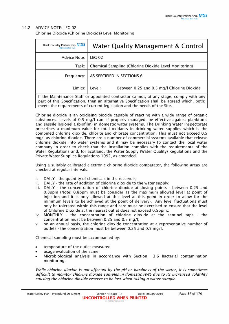
Water Safety Plan - Procedural Document Version 4: Issue 1.4 Date: January 2019 Page 87 of 170 UNCONTROLLED WHEN PRINTED
©HYDROP ECS 2019
14.2 ADVICE NOTE: LEG 02:
Chlorine Dioxide (Chlorine Dioxide) Level Monitoring
Water Quality Management & Control
Advice Note: LEG 02
Task: Chemical Sampling (Chlorine Dioxide Level Monitoring)
Frequency: AS SPECIFIED IN SECTIONS 6
Limits: Level: Between 0.25 and 0.5 mg/l Chlorine Dioxide
If the Maintenance Staff or appointed contractor cannot, at any stage, comply with any part of this Specification, then an alternative Specification shall be agreed which, both; meets the requirements of current legislation and the needs of the Site.
Chlorine dioxide is an oxidising biocide capable of reacting with a wide range of organic substances. Levels of 0.5 mg/l can, if properly managed, be effective against planktonic and sessile legionella (biofilm) in domestic water systems. The Drinking Water Inspectorate prescribes a maximum value for total oxidants in drinking water supplies which is the combined chlorine dioxide, chlorite and chlorate concentration. This must not exceed 0.5 mg/l as chlorine dioxide. There are a number of commercial systems available that release chlorine dioxide into water systems and it may be necessary to contact the local water company in order to check that the installation complies with the requirements of the Water Regulations and, for Scotland, the Water Supply (Water Quality) Regulations and the Private Water Supplies Regulations 1992, as amended. Using a suitably calibrated electronic chlorine dioxide comparator, the following areas are checked at regular intervals: i. DAILY - the quantity of chemicals in the reservoir; ii. DAILY - the rate of addition of chlorine dioxide to the water supply; iii. DAILY - the concentration of chlorine dioxide at dosing points - between 0.25 and
0.8ppm (Note: 0.8ppm must be consider as the maximum allowed level at point of injection and it is only allowed at this level at this point in order to allow for the minimum levels to be achieved at the point of delivery). Any level fluctuations must only be tolerated within this range and care must be exercised to ensure that the level of Chlorine Dioxide at the nearest outlet does not exceed 0.5ppm.;
iv. MONTHLY - the concentration of chlorine dioxide at the sentinel taps - the concentration must be between 0.25 and 0.5 mg/l;
v. on an annual basis, the chlorine dioxide concentration at a representative number of outlets - the concentration must be between 0.25 and 0.5 mg/l.
Chemical sampling must be accompanied by: temperature of the outlet measured usage evaluation of the same Microbiological analysis in accordance with Section 3.6 Bacterial contamination
monitoring. While chlorine dioxide is not affected by the pH or hardness of the water, it is sometimes difficult to monitor chlorine dioxide samples in domestic HWS due to its increased volatility causing the chlorine dioxide reserve to be lost when taking a water sample.

Water Safety Plan - Procedural Document Version 4: Issue 1.4 Date: January 2019 Page 88 of 170 UNCONTROLLED WHEN PRINTED
©HYDROP ECS 2019
14.3 ADVICE NOTE: LEG 03:
Water Storage Tank – Temperature Monitoring
Water Quality Management & Control
Advice Note: LEG 03
Task: Water Storage Tank – Temperature Monitoring
Frequency: AS SPECIFIED IN SECTIONS 6
Limits: INCOMING MAINS TEMPERATURE: <20oC STORED WATER TEMPERATURE: <20oC
If the Maintenance Staff or appointed contractor cannot, at any stage, comply with any part of this Specification, then an alternative Specification shall be agreed which, both; meets the requirements of current legislation and the needs of the Site.
Using a calibrated thermometer, measure and report the following: i. Ambient (external temperature) ii. Tank room temperature iii. Stored water temperature (Temperature of the tanked water must be monitored via
the drain point if practicable) iv. Supply temperature
Note: Remember to measure and record temperature reading from as far away from the
ball cock as possible. Care must be taken as not to contaminate the stored water by the use of unclean temperature probes.

Water Safety Plan - Procedural Document Version 4: Issue 1.4 Date: January 2019 Page 89 of 170 UNCONTROLLED WHEN PRINTED
©HYDROP ECS 2019
14.4 ADVICE NOTE: LEG 04:
Water Storage Tank – Visual General Inspection
Water Quality Management & Control
Advice Note: LEG 04
Task: Water Storage Tank – Visual General Inspection
Frequency: AS SPECIFIED IN SECTIONS 6
Limits: WATER SUPPLY (FITTINGS) REGULATIONS 1999 COMPLIANT
If the Maintenance Staff or appointed contractor cannot, at any stage, comply with any part of this Specification, then an alternative Specification shall be agreed which, both; meets the requirements of current legislation and the needs of the Site.
i. Using a calibrated thermometer, measure and report the following:
Ambient (external temperature); Tank room temperature; Stored water temperature (Temperature of the tanked water must be monitored via the drain point if practicable); Supply temperature
ii. Visually inspect tank room for bird and/or rodent infestation and state amount: 0 = None; 1 = slight and 10 = heavy
iii. If insulation allows for inspection of the external condition of the tank walls, inspect for corrosion pitting and leaks.
iv. Visually inspect internal walls of tank for signs of scale deposition, corrosion and slime deposits.
v. Visually inspect tank and associated valves/pipework for leaks. vi. Visually inspect bottom of tank for sludge deposition and state amount:
0 = None; 1 = slight and 10 = heavy vii. Visually inspect water surface for; dirt, oil films, insects and state amount:
0 = None; 1 = slight and 10 = heavy viii. Visually inspect for slimy deposits on the internal walls of tank and state the colour of
substance and state amount; 0 = None; 1 = slight and 10 = heavy
ix. Visually inspect for algae growth indicated by either green or red plant like growth on water surface
i. Visually inspect the insulation for signs of wear and tear and areas where the insulation has been removed
ii. Visually inspect that the lid is correctly fitted and that any bolts are securely tightened.
iii. Visually inspect that all insect/rodent screens fitted are clear from debris so that water can flow easily.
iv. Visually inspect all valves for correct operation, signs of corrosion and leaks. v. Visually inspect all booster pumps fitted for correct operation. vi. Indicate the date that the tank was last cleaned and disinfected and indicate whether
it was disinfected as routine or due to adverse conditions.

Water Safety Plan - Procedural Document Version 4: Issue 1.4 Date: January 2019 Page 90 of 170 UNCONTROLLED WHEN PRINTED
©HYDROP ECS 2019
14.5 ADVICE NOTE: LEG 05:
Storage Calorifiers – 24 hr Temperature Profiling
Water Quality Management & Control
Advice Note: LEG 05
Task: Storage Calorifiers – 24 hr Temperature Profiling
Frequency: AS SPECIFIED IN SECTIONS 6
Limits:
FLOW TEMPERATURE: ≥60oC RETURN TEMPERATURE: ≥50OC DRAIN TEMPERATURE: ≥60OC COLD FEED TEMPERATURE: <20oC
If the Maintenance Staff or appointed contractor cannot, at any stage, comply with any part of this Specification, then an alternative Specification shall be agreed which, both; meets the requirements of current legislation and the needs of the Site.
Operating temperatures of storage calorifiers must be maintained within the following limits:
FLOW TEMPERATURE: ≥60oC RETURN TEMPERATURE: ≥50OC DRAIN TEMPERATURE: ≥60OC COLD FEED TEMPERATURE: <20oC
i. Where the unit is monitored using BMS, collect the readings of all the fields listed above, for at least a 24hr period and consider the results. Adjust control parameters as necessary.
ii. Where the unit is not monitored using BMS, attach a data-logger on the flow, return,
and cold feed (as close to the unit as practicable) and collect temperature data for at least a 24hr period and consider the results. Adjust control parameters as necessary and the frequency and duration of temperature logging dependent upon results.

Water Safety Plan - Procedural Document Version 4: Issue 1.4 Date: January 2019 Page 91 of 170 UNCONTROLLED WHEN PRINTED
©HYDROP ECS 2019
14.6 ADVICE NOTE: LEG 06:
Storage Calorifiers –Manual Temperature Monitoring
Water Quality Management & Control
Advice Note: LEG 06
Task: Storage Calorifiers – Manual Temperature Monitoring
Frequency: AS SPECIFIED IN SECTIONS 6
Limits:
FLOW TEMPERATURE: ≥60oC RETURN TEMPERATURE: ≥50OC DRAIN TEMPERATURE: ≥60OC COLD FEED TEMPERATURE: <20oC
If the Maintenance Staff or appointed contractor cannot, at any stage, comply with any part of this Specification, then an alternative Specification shall be agreed which, both; meets the requirements of current legislation and the needs of the Site.
i. Measure and record the “Set” temperature setting of the thermostat (if fitted and
calibrated). Temperature to exceed 60oC. ii. Measure and record the “Flow” temperature using a contact thermometer or fitted
gauge. Temperature to be taken from “Flow” pipework as close to the Calorifier as possible. Temperature to exceed 60oC.
iii. Measure and record the “Return“ temperature using a contact thermometer or fitted gauge. Temperature to be taken from “Return” pipework as close to the Calorifier as possible. Temperature to exceed 50oC.
iv. Measure and record the “Return“ temperature using a contact thermometer or fitted gauge. Temperature to be taken from Primary, Secondary and Tertiary “Return” pipework loops where practicable. Temperature to exceed 55oC.
v. Isolate Cold Feed and open drain point and measure and record temperature. Temperature to exceed 60oC.
vi. Measure and record the “Cold Feed“ temperature using a contact thermometer or fitted gauge. Temperature to be taken from “Cold Feed” pipework one metre from the Calorifier as possible. Temperature NOT to exceed 20oC.
If contact probe is to be used for temperature monitoring through copper pipework, a 2oC temperature adjustment must be added to the recorded temperature before reporting temperature on the Log-sheet. The temperature measurements shall be carried out at different times during the day in order to allow indicative temperature monitoring of the vessel during a typical daily usage profile. Guidance Note 11: Where designated sentinel outlets are fitted with TMV/TMT, the temperature of the hot and cold supply must be measured by surface (contact) temperature measurement. If contact probe is to be used for temperature monitoring through copper pipework, Temperatures must be collected as described in BSRIA Application Guide AG 4/94 – Guide to Legionellosis – Temperature measurements for hot and cold water services. The temperature measurements shall be carried out at different times during the day in order to allow indicative temperature monitoring of the system during a typical daily usage profile.

Water Safety Plan - Procedural Document Version 4: Issue 1.4 Date: January 2019 Page 92 of 170 UNCONTROLLED WHEN PRINTED
©HYDROP ECS 2019
14.7 ADVICE NOTE: LEG 07:
Storage Calorifiers –Visual General Inspection including drain flushing
Water Quality Management & Control
Advice Note: LEG 07
Task: Storage Calorifiers – General Visual Inspection including drain flushing
Frequency: AS SPECIFIED IN SECTIONS 6
Limits: NO CORROSION NO SLUDGE DEPOSITION CORRECT TEMPERATURE LIMITS
If the Maintenance Staff or appointed contractor cannot, at any stage, comply with any part of this Specification, then an alternative Specification shall be agreed which, both; meets the requirements of current legislation and the needs of the Site.
i. Ensure operational status of Calorifier by checking the status of the associated
isolation valves ii. If the Calorifier is OFF, indicate the date it came Off-line iii. Confirm status of Inlet Valve and Confirm status of Outlet Valve iv. Confirm the operational status of the circulation pump(s) and destratification pumps v. Visually inspect Calorifier and associated valves for leaks vi. Visually inspect all pipework for signs of corrosion and leaks, and visually inspect the
condition of insulation fitted. Visually inspect all valves for correct operation, signs of corrosion and leaks. Visually inspect all pumps fitted for correct operation and leaks
vii. Measure and record the temperature setting of the thermostat (if fitted) viii. Measure and record the “Flow and Return“ temperature using a contact thermometer
or fitted gauge. Temperature to be taken from “flow” pipework as close to the Calorifier as possible.
ix. Isolate CW feed and open drain point into a bucket and collect approximately the 1st litre of water discharged. Measure and record the condition, viscosity and colour of this water.
x. Check for colour, viscosity and sludge deposition amount. Measure and record the temperature of the water collected.
xi. Using a contact thermometer, measure and record the temperature of the calorifier at; the top, middle and bottom. If there is more than 10oC difference between the top temperature and the bottom temperature then the calorifier is suffering from temperature stratification. If a contact thermometer cannot be used, then measure and record the difference in the “flow” temperature and the “drain” temperature.
xii. Visually inspect the insulation for signs of wear and tear and areas where the insulation has been removed
xiii. Visually inspect that any gauges fitted are operating correctly. Compare against calibrated instruments.
xiv. Open the CW feed valve and then open the drain point allowing enough water to flow through so that any water discoloration is removed.
xv. Indicate the date that the calorifier was last pasteurised and indicate whether it was disinfected as routine or due to adverse conditions
xvi. Indicate the date of the last insurance inspection, if applicable.

Water Safety Plan - Procedural Document Version 4: Issue 1.4 Date: January 2019 Page 93 of 170 UNCONTROLLED WHEN PRINTED
©HYDROP ECS 2019
14.8 ADVICE NOTE: LEG 08:
Circulation and destratification pumps visual inspections and servicing
Water Quality Management & Control
Advice Note: LEG 08
Task: Circulation and destratification pumps visual inspections and servicing
Frequency: AS SPECIFIED IN SECTIONS 6
Limits: CORRECT OPERATION
If the Maintenance Staff or appointed contractor cannot, at any stage, comply with any part of this Specification, then an alternative Specification shall be agreed which, both; meets the requirements of current legislation and the needs of the Site.
i. Check circulating pumps for adequate performance to ensure a minimum circulating
temperature of 50ºC. ii. In case of a standby pump being available for immediate connection into the HWS
circulating system, switch on to ensure that the standby on backup pump can be brought into service.
It is not permissible to shut down the pumped circulation system. To do so will lead to the loss of the required system temperature. Guidance Note 12: Where designated sentinel outlets are fitted with TMV/TMT, the temperature of the hot and cold supply must be measured by surface (contact) temperature measurement. If contact probe is to be used for temperature monitoring through copper pipework, Temperatures must be collected as described in BSRIA Application Guide AG 4/94 – Guide to Legionellosis – Temperature measurements for hot and cold water services. The temperature measurements shall be carried out at different times during the day in order to allow indicative temperature monitoring of the system during a typical daily usage profile.

Water Safety Plan - Procedural Document Version 4: Issue 1.4 Date: January 2019 Page 94 of 170 UNCONTROLLED WHEN PRINTED
©HYDROP ECS 2019
14.9ADVICE NOTE: LEG 09:
Expansion and Pressurisation Vessel Flushing (Non Flow-Through types only)
Water Quality Management & Control
Advice Note: LEG 09
Task: Expansion Vessel Flushing (Non Flow-Through types only)
Frequency: AS SPECIFIED IN SECTIONS 6
If the Maintenance Staff or appointed contractor cannot, at any stage, comply with any part of this Specification, then an alternative Specification shall be agreed which, both; meets the requirements of current legislation and the needs of the Site.
Doubts have been expressed about the desirability of using single entry expansion vessels on hot water systems. The use of single entry expansion vessels effectively forms a vertical dead-leg through which there is no flow of water and concern has been expressed about the possibility of bacterial growth within the vessel. It is considered preferable therefore, that an expansion vessel with both inlet and outlet connections must be installed, wherever practicable, so that the water content of the vessel is constantly changed. This will also allow for compliance with BS 6144 and BS 6920. Where expansion vessels are of the single entry type they must be fitted with appropriate drain valves to facilitate flushing of the unit 2 x weekly. Care must be taken to avoid damage to the diaphragm.

Water Safety Plan - Procedural Document Version 4: Issue 1.4 Date: January 2019 Page 95 of 170 UNCONTROLLED WHEN PRINTED
©HYDROP ECS 2019
14.10 ADVICE NOTE: LEG 10:
Cistern Type Water Heaters – Temperature Monitoring
Water Quality Management & Control
Advice Note: LEG 10
Task: Cistern Type Water Heaters – Temperature Monitoring
Frequency: AS SPECIFIED IN SECTIONS 6
Limits: UNIT TEMPERATURE: ≥60oC OUTLET TEMPERATURE: ≥55OC within 1 min
If the Maintenance Staff or appointed contractor cannot, at any stage, comply with any part of this Specification, then an alternative Specification shall be agreed which, both; meets the requirements of current legislation and the needs of the Site.
i. Measure and record the “Set” temperature setting of the thermostat (if fitted and
calibrated). Temperature to be at least 60oC. ii. Measure and record the temperature of the furthest outlet supplied by the unit.
Temperature to be at least 55oC within 1 min. If contact probe is to be used for temperature monitoring through copper pipework, a 2oC temperature adjustment must be added to the recorded temperature before reporting temperature on the Log-sheet. The temperature measurements shall be carried out at different times during the day in order to allow indicative temperature monitoring of the vessel during a typical daily usage profile. Guidance Note 13: Where designated sentinel outlets are fitted with TMV/TMT, the temperature of the hot and cold supply must be measured by surface (contact) temperature measurement. If contact probe is to be used for temperature monitoring through copper pipework, Temperatures must be collected as described in BSRIA Application Guide AG 4/94 – Guide to Legionellosis – Temperature measurements for hot and cold water services. The temperature measurements shall be carried out at different times during the day in order to allow indicative temperature monitoring of the system during a typical daily usage profile.

Water Safety Plan - Procedural Document Version 4: Issue 1.4 Date: January 2019 Page 96 of 170 UNCONTROLLED WHEN PRINTED
©HYDROP ECS 2019
14.11 ADVICE NOTE: LEG 11:
Cistern Type Water Heaters – Inspection of Tank Section
Water Quality Management & Control
Advice Note: LEG 11
Task: Cistern Type Water Heaters – Inspection of Tank Section
Frequency: AS SPECIFIED IN SECTIONS 6
Limits: WATER SUPPLY (FITTINGS) REGULATIONS 1999 COMPLIANT
If the Maintenance Staff or appointed contractor cannot, at any stage, comply with any part of this Specification, then an alternative Specification shall be agreed which, both; meets the requirements of current legislation and the needs of the Site.
i. If casing allows for inspection of the external condition of the unit walls, inspect for
corrosion pitting and leaks. ii. Visually inspect tank and associated valves/pipework for leaks. iii. Visually inspect bottom of tank for sludge deposition and state amount:
0 = None, 1 = slight and 10 = heavy iv. Visually inspect internal walls of tank for corrosion and state amount:
0 = None, 1 = slight and 10 = heavy v. Visually inspect water surface for; dirt, oil films, insects and state amount:
0 = None, 1 = slight and 10 = heavy vi. Visually inspect for slimy deposits on the internal walls of tank and state the colour of
substance and state amount; 1 = slight and 10 = heavy vii. Visually inspect for algae growth indicated by either green or red plant like growth on
water surface viii. Visually inspect the insulation of the unit (if practicable) for signs of wear and tear ix. Visually inspect that the lid is correctly fitted x. Visually inspect that all insect/rodent screens fitted are clear from debris so that
water can flow easily. xi. Visually inspect that the ball valve opens and closes correctly xii. Visually inspect all pipework for signs of corrosion and leaks, and check the condition
of insulation fitted. xiii. Indicate the date that the tank was last cleaned and disinfected and indicate whether
it was disinfected as routine or due to adverse conditions.
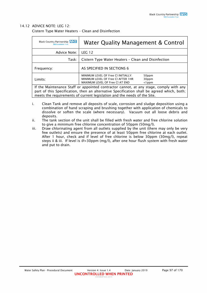
Water Safety Plan - Procedural Document Version 4: Issue 1.4 Date: January 2019 Page 97 of 170 UNCONTROLLED WHEN PRINTED
©HYDROP ECS 2019
14.12 ADVICE NOTE: LEG 12:
Cistern Type Water Heaters – Clean and Disinfection
Water Quality Management & Control
Advice Note: LEG 12
Task: Cistern Type Water Heaters – Clean and Disinfection
Frequency: AS SPECIFIED IN SECTIONS 6
Limits: MINIMUM LEVEL OF Free Cl INITIALLY: 50ppm MINIMUM LEVEL OF Free Cl AFTER 1HR 30ppm MAXIMUM LEVEL OF Free Cl AT END <1ppm
If the Maintenance Staff or appointed contractor cannot, at any stage, comply with any part of this Specification, then an alternative Specification shall be agreed which, both; meets the requirements of current legislation and the needs of the Site.
i. Clean Tank and remove all deposits of scale, corrosion and sludge deposition using a
combination of hand scraping and brushing together with application of chemicals to dissolve or soften the scale (where necessary). Vacuum out all loose debris and deposits.
ii. The tank section of the unit shall be filled with fresh water and free chlorine solution to give a minimum free chlorine concentration of 50ppm (50mg/l).
iii. Draw chlorinating agent from all outlets supplied by the unit (there may only be very few outlets) and ensure the presence of at least 50ppm free chlorine at each outlet. After 1 hour, check and if level of free chlorine is below 30ppm (30mg/l), repeat steps ii & iii. If level is @>30ppm (mg/l), after one hour flush system with fresh water and put to drain.

Water Safety Plan - Procedural Document Version 4: Issue 1.4 Date: January 2019 Page 98 of 170 UNCONTROLLED WHEN PRINTED
©HYDROP ECS 2019
14.13 ADVICE NOTE: LEG 13:
Low Volume Water Heater @ >15 litres– Temperature Monitoring
Water Quality Management & Control
Advice Note: LEG 13
Task: Low Volume Water Heater @ >15 litres– Temperature Monitoring
Frequency: AS SPECIFIED IN SECTIONS 6
Limits: UNIT TEMPERATURE: ≥60oC OUTLET TEMPERATURE: ≥50OC within 1 min
If the Maintenance Staff or appointed contractor cannot, at any stage, comply with any part of this Specification, then an alternative Specification shall be agreed which, both; meets the requirements of current legislation and the needs of the Site.
i. Measure and record the “Set” temperature setting of the thermostat (if fitted and
calibrated). Temperature to be at least 60oC. ii. Measure and record the temperature of the furthest outlet supplied by the unit.
Temperature to be at least 55oC within 1 min. If contact probe is to be used for temperature monitoring through copper pipework, a 2oC temperature adjustment must be added to the recorded temperature before reporting temperature on the Log-sheet. Where the measured contact temperature is >2oC from the nearest direct fed outlet, then report the nearest direct fed outlet temperature. The temperature measurements shall be carried out at different times during the day in order to allow indicative temperature monitoring of the vessel during a typical daily usage profile. Guidance Note 14: Where designated sentinel outlets are fitted with TMV/TMT, the temperature of the hot and cold supply must be measured by surface (contact) temperature measurement. If contact probe is to be used for temperature monitoring through copper pipework, Temperatures must be collected as described in BSRIA Application Guide AG 4/94 – Guide to Legionellosis – Temperature measurements for hot and cold water services. The temperature measurements shall be carried out at different times during the day in order to allow indicative temperature monitoring of the system during a typical daily usage profile.

Water Safety Plan - Procedural Document Version 4: Issue 1.4 Date: January 2019 Page 99 of 170 UNCONTROLLED WHEN PRINTED
©HYDROP ECS 2019
14.14 ADVICE NOTE: LEG 14:
Combination Boiler – Temperature Monitoring
Water Quality Management & Control
Advice Note: LEG 14
Task: Combination Boiler – Temperature Monitoring
Frequency: AS SPECIFIED IN SECTIONS 6
Limits: UNIT TEMPERATURE: ≥60oC OUTLET TEMPERATURE: ≥55OC within 1 min
If the Maintenance Staff or appointed contractor cannot, at any stage, comply with any part of this Specification, then an alternative Specification shall be agreed which, both; meets the requirements of current legislation and the needs of the Site.
i. Measure and record the “Set” temperature setting of the thermostat (if fitted and
calibrated). Temperature to be at least 60oC. ii. Measure and record the temperature of the furthest outlet supplied by the unit.
Temperature to be at least 55oC within 1 min. If contact probe is to be used for temperature monitoring through copper pipework, a 2oC temperature adjustment must be added to the recorded temperature before reporting temperature on the Log-sheet. Where the measured contact temperature is >2oC from the nearest direct fed outlet, then report the nearest direct fed outlet temperature. The temperature measurements shall be carried out at different times during the day in order to allow indicative temperature monitoring of the vessel during a typical daily usage profile. Guidance Note 15: Where designated sentinel outlets are fitted with TMV/TMT, the temperature of the hot and cold supply must be measured by surface (contact) temperature measurement. If contact probe is to be used for temperature monitoring through copper pipework, Temperatures must be collected as described in BSRIA Application Guide AG 4/94 – Guide to Legionellosis – Temperature measurements for hot and cold water services. The temperature measurements shall be carried out at different times during the day in order to allow indicative temperature monitoring of the system during a typical daily usage profile.

Water Safety Plan - Procedural Document Version 4: Issue 1.4 Date: January 2019 Page 100 of 170 UNCONTROLLED WHEN PRINTED
©HYDROP ECS 2019
14.15 ADVICE NOTE: LEG 15:
Instant Water Heater @ <15 litres– Temperature Monitoring – Temperature Monitoring
Water Quality Management & Control
Advice Note: LEG 15
Task: Instant Water Heater @ <15 litres– Temperature Monitoring – Temperature Monitoring
Frequency: AS SPECIFIED IN SECTIONS 6
Limits: UNIT/OUTLET TEMPERATURE: Comfort Temperature and ≤41oC if
patient area and outlet is not fitted with a TMV
If the Maintenance Staff or appointed contractor cannot, at any stage, comply with any part of this Specification, then an alternative Specification shall be agreed which, both; meets the requirements of current legislation and the needs of the Site.
Units of this type, because of the limited stored water volume, do not usually need to be operated within the temperature profile and limits prescribed for larger systems (≥60oC for the ‘flow’ and (≥50/55oC for the ‘return’ and ‘outlet’) which are necessary for thermal disinfection. It may be possible to operate these units at “safe” temperatures of ≤41.0oC although they must be switched-on at all times to ensure and encourage adequate use. However, infrequent use of these units (less than 2 x weekly) would increase the potential of bacterial growth and proliferation (as would be the case in all infrequently used areas throughout the system – both hot and cold), although particularly in this case because of the low temperatures operated. Guidance Note 16: Where designated sentinel outlets are fitted with TMV/TMT, the temperature of the hot and cold supply must be measured by surface (contact) temperature measurement. If contact probe is to be used for temperature monitoring through copper pipework, Temperatures must be collected as described in BSRIA Application Guide AG 4/94 – Guide to Legionellosis – Temperature measurements for hot and cold water services. The temperature measurements shall be carried out at different times during the day in order to allow indicative temperature monitoring of the system during a typical daily usage profile.

Water Safety Plan - Procedural Document Version 4: Issue 1.4 Date: January 2019 Page 101 of 170 UNCONTROLLED WHEN PRINTED
©HYDROP ECS 2019
14.16 ADVICE NOTE: LEG 16:
Thermostatic Mixing Valves/Taps – Temperature Monitoring
Water Quality Management & Control
Advice Note: LEG 16
Task: Thermostatic Mixing Valves/Taps – Temperature Monitoring
Frequency: AS SPECIFIED IN SECTIONS 6
Limits:
FROM THE TMV/TMT 41oC for whb. 41oC for showers. 44oC for baths. 38oC for bidets. TO THE TMV/TMT >55oC HWS to the TMV/TMT <20oC CWS to the TMV/TMT
If the Maintenance Staff or appointed contractor cannot, at any stage, comply with any part of this Specification, then an alternative Specification shall be agreed which, both; meets the requirements of current legislation and the needs of the Site.
SHOWERS, BATHS AND BIDETS i. Measure and record the “Initial” and “Final” outlet temperature, of each shower and
bath fitted with a Thermostatic Mixing Valve/Tap (TMV/TMT or otherwise). The measurements shall be carried out immediately and after allowing the water to run for 1 minute at full-flow respectively. The “Initial” and “Final” outlet temperature measured shall not exceed: a. 41oC for showers. b. 44oC for baths. c. 38oC for bidets. Where these temperatures are exceeded, the TMV/TMT shall be adjusted in order to allow the unit to operate within the recommended temperature limits described above.
ii. Using an electronic and calibrated thermometer with a suitable contact probe, measure and record the temperature of the HWS and CWS supply pipes of each TMV/TMT. The temperature of the CWS shall not exceed 20oC and the temperature of the HWS shall not be less than 55oC. The measurements shall be carried out following task 1. (i).
SINKS AND BASINS AND OTHER NON FULL BODY IMMERSION OUTLETS i. Measure and record the “Initial” and “Final” outlet temperature, of the HOT water
outlet of each sink, basin and other non-full body immersion outlets fitted with a Thermostatic Mixing Valve/Tap (TMV/TMT or otherwise). The measurements shall be carried out immediately and after allowing the water to run for 1 minute at full-flow respectively. The “Initial” and “Final” outlet temperature measured shall not exceed 41oC Where these temperatures are exceeded, the TMV/TMT shall be adjusted in order to allow the unit to operate within the recommended temperature limits described above.
ii. Using an electronic and calibrated thermometer with a suitable contact probe, measure and record the temperature of the HWS supply pipe ONLY of each TMV/TMT. The temperature of the HWS shall not be less than 55oC. The measurements shall be carried out following task 2. (i).

Water Safety Plan - Procedural Document Version 4: Issue 1.4 Date: January 2019 Page 102 of 170 UNCONTROLLED WHEN PRINTED
©HYDROP ECS 2019
iii. Measure and record the COLD water outlets of each sink, basin and other non-full body immersion outlets fitted with a Thermostatic Mixing Valve/Tap (TMV/TMT or otherwise). The measurements shall be carried out immediately and after allowing the water to run for 2 minutes at full-flow respectively. The outlet temperature measured shall not exceed 20oC.
Guidance Note 17: Where designated sentinel outlets are fitted with TMV/TMT, the temperature of the hot and cold supply must be measured by surface (contact) temperature measurement. If contact probe is to be used for temperature monitoring through copper pipework, Temperatures must be collected as described in BSRIA Application Guide AG 4/94 – Guide to Legionellosis – Temperature measurements for hot and cold water services. The temperature measurements shall be carried out at different times during the day in order to allow indicative temperature monitoring of the system during a typical daily usage profile.

Water Safety Plan - Procedural Document Version 4: Issue 1.4 Date: January 2019 Page 103 of 170 UNCONTROLLED WHEN PRINTED
©HYDROP ECS 2019
14.17 ADVICE NOTE: LEG 17:
Thermostatic Mixing Valves/Taps – General Condition Inspections & servicing
Water Quality Management & Control
Advice Note: LEG 17
Task: Thermostatic Mixing Valves/Taps – General Condition Inspections & servicing
Frequency: AS SPECIFIED IN SECTIONS 6
Limits:
FROM THE TMV/TMT 41oC for showers. 44oC for baths. 38oC for bidets. TO THE TMV/TMT >55oC HWS to the TMV/TMT <20oC CWS to the TMV/TMT
If the Maintenance Staff or appointed contractor cannot, at any stage, comply with any part of this Specification, then an alternative Specification shall be agreed which, both; meets the requirements of current legislation and the needs of the Site.
i. Inlet check valves (if fitted): Measure inlet pipework surface temperature for
indication of cross-flow. A more effective test can be considered if appropriate, utilising drain points positioned between isolating and check-valves.
ii. Temperature measurements: a) fail-safe; b) adjustable/pre-set maximum, Operate flow controls and measure blended temperature. Measure maximum and minimum blended temperature. For thermostat and pressure-balanced mixers, blend temperature should stabilise quickly and remain within +/-1oC of set value. For manual mixers, refer to commissioning data.
iii. Thermal shut-down (TMV/TMT): Operate mixer at blended temperature, then isolate cold supply. Valve must shut down in accordance with the manufacturer’s data.
iv. Temperature control: Operate mixer at blended temperature, then open other local cold outlets off common supply. Measure shift in blend temperature with reference data compiled at the commissioning stage.
v. Strainers: Isolate and visually inspect and clean as necessary. vi. Flow control(s): Operate fully and check for effective closure. If time delay is
incorporated, measure length of flow cycle. vii. Automatic drain valve (if fitted): Check effective operation. viii. Mixing valve: a) temperature control; b) flow control(s); c) inlet check valves. Where
specified by manufactures guidance and/or site conditions and inspection confirms the requirement, carry out visual inspection of internal serviceable mechanisms. Clean or renew components as necessary. Lubricate as indicated in manufacturer’s data. Refer to manufacturer’s data for recommended procedures and cleaning agents/lubricants. For products of (serviceable) cartridge construction, fit and commission exchange units if required. Service displaced units in workshop as part of rolling planned maintenance procedure.
i. Supply pipe-work: Visually inspect for damage leaks, etc. and rectify. ii. For all new installations, record the supply pressures to allow the appointed person
to compare these pressures and temperatures to confirm agreement with commissioning data.
x. Controls: Operate inlet valves and check individual flow rates of hot and cold water supplies. If valve is stripped down and reassembled all parts should be greased as recommended in the manufacturer’s maintenance instructions.
xi. Thermostat: Check mixed water outlet setting. Ensure thermometer bulb is immersed in flowing water if measurement taken at shower head

Water Safety Plan - Procedural Document Version 4: Issue 1.4 Date: January 2019 Page 104 of 170 UNCONTROLLED WHEN PRINTED
©HYDROP ECS 2019
xii. Temperature limiter: Measure mixed water outlet temperature at limit safety stop. Limiter setting 41oC.
xiii. Inlet check valves (where fitted): Check operation. Non-return valves may have been removed if operating with balanced pressure supplies).
Guidance Note 18: Where designated sentinel outlets are fitted with TMV/TMT, the temperature of the hot and cold supply must be measured by surface (contact) temperature measurement. If contact probe is to be used for temperature monitoring through copper pipework, Temperatures must be collected as described in BSRIA Application Guide AG 4/94 – Guide to Legionellosis – Temperature measurements for hot and cold water services. The temperature measurements shall be carried out at different times during the day in order to allow indicative temperature monitoring of the system during a typical daily usage profile.

Water Safety Plan - Procedural Document Version 4: Issue 1.4 Date: January 2019 Page 105 of 170 UNCONTROLLED WHEN PRINTED
©HYDROP ECS 2019
14.18 ADVICE NOTE: LEG 18:
Thermostatic Mixing Valves/Taps – Clean, Descale and Disinfection
Water Quality Management & Control
Advice Note: LEG 18
Task: Thermostatic Mixing Valves/Taps – Clean, Descale and Disinfection
Frequency: AS SPECIFIED IN SECTION 6
Limits: 100ppm free chlorine for 20 minutes minimum
If the Maintenance Staff or appointed contractor cannot, at any stage, comply with any part of this Specification, then an alternative Specification shall be agreed which, both; meets the requirements of current legislation and the needs of the Site.
When site conditions are found to result in scale build-up within a valve, the valve should be descaled and disinfected as per this specification to a frequency determined by site tests and inspections. i. Each TMV/TMT shall be removed from its location and replaced with a new or
previously serviced TMV/TMT. The removed TMV/TMT shall be taken to a suitably equipped work-shop for service.
ii. At the work-shop, each TMV/TMT shall be dismantled and physically cleaned from all scale deposits and scale deposition (using a suitable descaling solution where necessary).
iii. All components, including strainers, aerators and flow straighteners shall be disinfected (this applies to all cleaned and new components). All components shall be flushed with clean water and immersed in a free chlorine disinfectant solution (100 ppm) for 20 minutes minimum.
iv. Remove components from disinfectant solution and rinse with clean water to remove presence of disinfectant.
v. Reassemble, refit and test operation of valve, including fail-safe test. vi. Rinse in clean water, allow to drip-dry and store in a cool and dry place.

Water Safety Plan - Procedural Document Version 4: Issue 1.4 Date: January 2019 Page 106 of 170 UNCONTROLLED WHEN PRINTED
©HYDROP ECS 2019
14.19 ADVICE NOTE: LEG 19:
Shower – Temperature Monitoring
Water Quality Management & Control
Advice Note: LEG 19
Task: Shower – Temperature Monitoring
Frequency: AS SPECIFIED IN SECTION 6
Limits:
FROM THE TMV 41oC (+/-oC) for showers. TO THE TMV >55oC HWS to the TMV <20oC CWS to the TMV
If the Maintenance Staff or appointed contractor cannot, at any stage, comply with any part of this Specification, then an alternative Specification shall be agreed which, both; meets the requirements of current legislation and the needs of the Site.
i. Measure and record the “Initial” and “Final” outlet temperature, of each shower fitted
with a Thermostatic Mixing Valve (TMV or otherwise). The measurements shall be carried out immediately and after allowing the water to run for 1 minute at full-flow respectively. The “Initial” and “Final” outlet temperature measured shall not to exceed 41oC.
ii. Where this temperature is exceeded, the TMV shall be adjusted in order to allow the unit to operate within the recommended temperature limits described above.
iii. Using an electronic and calibrated thermometer with a suitable contact probe, measure and record the temperature of the HWS and CWS supply pipes of each TMV. The temperature of the CWS shall not exceed 20oC and the temperature of the HWS shall not be less than 55oC. The measurements shall be carried out following task 1. (i).
Guidance Note 19: Where designated sentinel outlets are fitted with TMV/TMT, the temperature of the hot and cold supply must be measured by surface (contact) temperature measurement. If contact probe is to be used for temperature monitoring through copper pipework, Temperatures must be collected as described in BSRIA Application Guide AG 4/94 – Guide to Legionellosis – Temperature measurements for hot and cold water services. The temperature measurements shall be carried out at different times during the day in order to allow indicative temperature monitoring of the system during a typical daily usage profile.

Water Safety Plan - Procedural Document Version 4: Issue 1.4 Date: January 2019 Page 107 of 170 UNCONTROLLED WHEN PRINTED
©HYDROP ECS 2019
14.20 ADVICE NOTE: LEG 20:
Shower – Head Replacement / Clean and Disinfection
Water Quality Management & Control
Advice Note: LEG 20
Task: Shower –Head Replacement / Clean and Disinfection
Frequency: AS SPECIFIED IN SECTIONS 6
Limits: New shower head Sodium hypochlorite (100 mg/l free chlorine) for 20 minutes minimum
If the Maintenance Staff or appointed contractor cannot, at any stage, comply with any part of this Specification, then an alternative Specification shall be agreed which, both; meets the requirements of current legislation and the needs of the Site.
SHOWER HEAD REPLACEMENT i. Examine shower head for signs of dirt, scale and slime deposition. ii. If any of the above is considered to be significant, replace existing shower head with
new, packaged shower head and dispose of the old shower head in an appropriate manner.
SHOWER HEAD CLEAN AND DISINFECTION i. Each shower-head and associated hose (where fitted) shall be removed from its
location and replaced with a new or previously serviced shower-head. The removed unit shall be taken to a suitably equipped work-shop for service.
ii. At the work-shop, each shower-head and associated hose shall be dismantled and physically cleaned from all scale deposits and debris deposition (using a suitable descaling solution where necessary on the shower-head only).
iii. Rinse in clean water iv. All components shall be disinfected (this applies to all cleaned and new components).
All components shall be flushed with clean water and immersed in a Sodium hypochlorite (100 mg/l free chlorine) for 20 minutes minimum.
v. Remove components from disinfectant solution and rinse with clean water to remove presence of disinfectant.
vi. Allow to drip-dry and store in a cool and dry place.
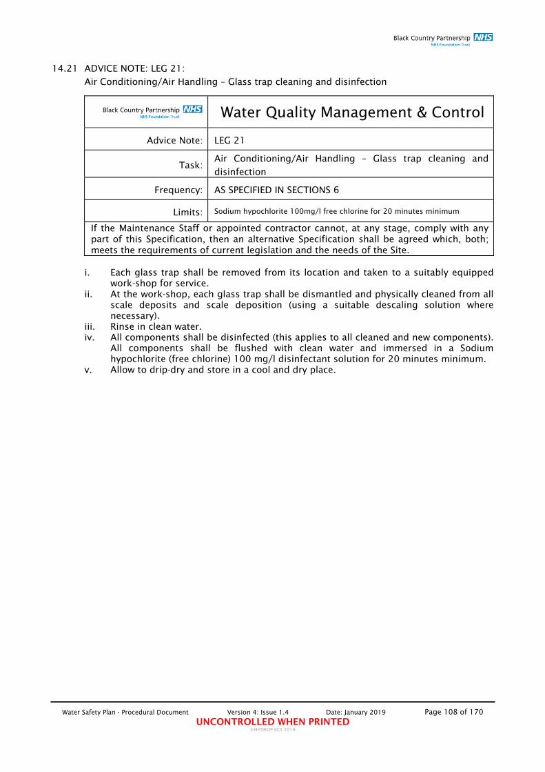
Water Safety Plan - Procedural Document Version 4: Issue 1.4 Date: January 2019 Page 108 of 170 UNCONTROLLED WHEN PRINTED
©HYDROP ECS 2019
14.21 ADVICE NOTE: LEG 21:
Air Conditioning/Air Handling – Glass trap cleaning and disinfection
Water Quality Management & Control
Advice Note: LEG 21
Task: Air Conditioning/Air Handling – Glass trap cleaning and disinfection
Frequency: AS SPECIFIED IN SECTIONS 6
Limits: Sodium hypochlorite 100mg/l free chlorine for 20 minutes minimum
If the Maintenance Staff or appointed contractor cannot, at any stage, comply with any part of this Specification, then an alternative Specification shall be agreed which, both; meets the requirements of current legislation and the needs of the Site.
i. Each glass trap shall be removed from its location and taken to a suitably equipped
work-shop for service. ii. At the work-shop, each glass trap shall be dismantled and physically cleaned from all
scale deposits and scale deposition (using a suitable descaling solution where necessary).
iii. Rinse in clean water. iv. All components shall be disinfected (this applies to all cleaned and new components).
All components shall be flushed with clean water and immersed in a Sodium hypochlorite (free chlorine) 100 mg/l disinfectant solution for 20 minutes minimum.
v. Allow to drip-dry and store in a cool and dry place.

Water Safety Plan - Procedural Document Version 4: Issue 1.4 Date: January 2019 Page 109 of 170 UNCONTROLLED WHEN PRINTED
©HYDROP ECS 2019
14.22 ADVICE NOTE: LEG 22:
Air Conditioning/Air Handling – General Inspection/Clean & disinfection
Water Quality Management & Control
Advice Note: LEG 22
Task: Air Conditioning/Air Handling – General Inspection / Clean & disinfection
Frequency: AS SPECIFIED IN SECTIONS 6
Limits: 500 mg/l Sodium hypochlorite (free chlorine) for 3 minutes minimum (using spray)
If the Maintenance Staff or appointed contractor cannot, at any stage, comply with any part of this Specification, then an alternative Specification shall be agreed which, both; meets the requirements of current legislation and the needs of the Site.
i. Report on the operational status of the unit. ii. Visually inspect the condition of the external surfaces of the unit and comment. iii. Visually inspect (if possible) the condition of the internal surfaces of the unit and
comment. If practicable, isolate unit in order to allow for thorough internal inspection to be carried out.
iv. Visually inspect the condition of all traps fitted and comment. v. Visually inspect (if possible) the condition of the drip-trays of the unit and comment.
If practicable, isolate unit in order to allow for thorough internal inspection of the drip-trays to be carried out. Alternatively, remove drip-trays from the system and inspect.
vi. Visually inspect (if possible) the condition of the eliminators of the unit and comment.
vii. Visually inspect (if possible) the condition of the filters fitted and comment. viii. Visually inspect (if possible) the condition of the humidifier components of the unit
and comment. ix. Visually inspect (if possible) the condition of the Chiller battery fitted and comment. x. Visually inspect (if possible) the condition of the Heater battery and comment. xi. Using clean cloth, wipe over the unit components to be disinfected. To disinfect,
spray the components with a Sodium hypochlorite (free chlorine) solution of 500 mg/l strength, using small hand spray. Allow to stand for 3 mins only. Spray with fresh clean water. Dry area with clean and clean cloth.
Guidance Note 20: On completion of cleaning, the ductwork should not be “fogged” with chemicals. This treatment has no lasting biocidal effect and is responsible for initiating the breakdown of the galvanised coating of ductwork. This will result in accelerated corrosion of the inside of the duct, with the products of corrosion being shed into the air stream. It will also significantly shorten service life.

Water Safety Plan - Procedural Document Version 4: Issue 1.4 Date: January 2019 Page 110 of 170 UNCONTROLLED WHEN PRINTED
©HYDROP ECS 2019
15. APPENDIX 4 – DETAILED AD‐HOC PROCESS SPECIFICATIONS
Process No. 1: Microbiological Sample Collection Protocol Process No. 2: Small sized pipework installation projects and associated
components pre and post installation cleaning and disinfection. Process No. 3: Water storage tank cleaning and disinfection. Process No. 4: Water storage tank drop-test. Process No. 5: Domestic hot and cold water services disinfection. Process No. 6: Calorifier Pasteurisation. Process No. 7: Domestic Water HWS distribution system pasteurisation. Process No. 8: Point of Use (POU) filter installation and replacement. Process No. 9: Dead Legs/Areas of Infrequent Use - Usage Evaluation & Flushing
Rationale Process No. 10: Dead Legs/Areas of Infrequent Use - Usage Evaluation & Flushing
Reporting Process Process No. 11: Management of Drinking Fountains. Process No. 12: Notification of Closure of Facility Process No. 13: Patient Susceptibility Risk Categorisation Assessment Process No. 14: Risk Assessment Status Enquiry pro-forma’ Process No. 15: Fault Notification and Remedial Actions Register Process No. 16: Clinical Assessment Process Adverse Water Sample Results
Notification Process No. 17: Contamination Risk Assessment Process No. 18: Management of Water Dispensers/Water Coolers Process No. 19: Identification and Size Demarcation of Scope of Works

Water Safety Plan - Procedural Document Version 4: Issue 1.4 Date: January 2019 Page 111 of 170 UNCONTROLLED WHEN PRINTED
©HYDROP ECS 2019
15.1 Microbiological sample collection protocol:
Water Quality Management & Control
Process No: 1
Task: WATER BIOLOGICAL SAMPLE COLLECTION PROTOCOL
Frequency: See section 3.6 Bacterial contamination monitoring
Limits: See Section 7 ENGINEERING CONTINGENCY MEASURES
MICROBIOLOGICAL SAMPLING METHODOLOGY
Microbiological Sampling must be carried out in accordance with: 1. BS EN ISO 5667-1:2006 BS 6068-6.1:2006 - Water quality Sampling - Part 1: Guidance on
the design of sampling programmes and sampling techniques. 2. BS ISO 5667-24:2016 Water quality - Sampling Part 24: Guidance on the auditing of water
quality sampling. 3. BS 7592:2008 - Sampling for Legionella bacteria in water systems – Code of practice. 4. BS 8554:2015 Code of practice for the sampling and monitoring of hot and cold water
services in buildings. 5. PHE - Hospital Waters - how to ensure high quality microbiological testing:2014 6. PHE - Examining food, water and environmental samples from healthcare environments -
Microbiological Guidelines:2013. Routine sample collection locations and type of analysis shall be agreed by the WSG and shall be representative of the system under surveillance and the reasons why a system is under surveillance. For new builds and refurbishments, sample locations and results parameters shall be determined and agreed between contractor and the WHG on a 'scheme-by-scheme' basis prior to the commencement of each scheme. All sampling rationales shall be ratified by the Trust consultant microbiologist and/or Authorising Engineer (Water). Microbiological sampling shall be carried out in order to consider two distinct areas of water quality management & control: a. localised bacterial contamination detected by: i. collecting and analysing a 'pre-flush' sample consisting of the unadulterated collection
of a sample of the water present at the outlet achieved by running the tap without flushing or cleaning the tap and collecting the water dispensed.
b. systemic bacterial contamination detected by: i. collecting and analysing a 'post-flush' sample consisting of the water collected following
spraying the outlet with a disinfectant solution equivalent to 1% sodium hypochlorite, leaving disinfectant in contact with the tap for at least two minutes then flushing the outlet for another two minutes before collecting the sample;
ii. collecting and analysing a 'fittings disinfected post-flush' sample consisting of the water
collected following the removal, cleaning/disinfection and re-fitting of all aerators/flow straighteners from the outlet and all strainers from associated thermostatic mixing

Water Safety Plan - Procedural Document Version 4: Issue 1.4 Date: January 2019 Page 112 of 170 UNCONTROLLED WHEN PRINTED
©HYDROP ECS 2019
valves and local pipework installation, flushing the outlet for another 2 minutes before collecting the sample.
These three types of samples are useful in determining the location and extent of the contamination detected and in determining the appropriate remedial corrective action required to remove the identified bacterial contamination. HEALTH AND SAFETY CONSIDERATIONS Sampling of water may occur in a wide variety of locations. Each location and reason for sampling has its own risks associated with it, and it is important to make an assessment of these risks and put appropriate control measures in place before commencing any sampling. Examples of risks include: 1. Wet floors that present a slip hazard when sampling from kitchen areas, toilet/rest
rooms, cooling towers etc. 2. Working at height when ladders/steps are required to reach water sampling points. 3. Manual handling risk when carrying large amounts of sampling equipment around. 4. Working in confined spaces when sampling from difficult-to-reach parts of water
systems. 5. Legionella infection risk if sampling from water sources that create aerosols, such as
cooling towers and showers. Appropriate precautions shall be taken to minimise aerosol production, as described in BS 7592:2008 (British Standards Institution, 2008). For example, running taps gently to reduce splashing; using a sterile plastic bag with one corner cut off to enclose the shower head and to funnel the water into a sampling container; sampling cooling towers from sampling points on the return service of the cooling water to the tower, rather than the tower itself. In addition, some specific safety notes have been included in the sections below: The following is a list of equipment that may be needed for sampling. The list is not intended to be exhaustive and not all items may be required for all types of sampling. 1. Sterile food-grade plastic bags 2. Laboratory supplied sterile sample bottles 3. Labels 4. Permanent waterproof marker pens and biros 5. Laboratory request forms for water samples 6. Nitrile (plastic) gloves 7. Alcohol medical wipes 8. Plastic shoe coverings 9. Cool boxes with separators, temperature data-loggers and 10% by volume of frozen ice-
packs (ice packs shall not be used for Legionella samples) 10. Digital camera 11. Digital voice recorder 12. Calibrated thermometer 13. Calibrated stop-watch 14. Calibrated disinfectant residual measuring device SAMPLE BOTTLES REQUIRED FOR THE COLLECTION OF WATER FOR DIFFERENT MICROBIOLOGICAL ANALYSES
Test Required Sample Bottles
Coliforms, Escherichia coli, Pseudomonas aeruginosa, Aerobic Colony Counts
1 x sterile 100 ml plastic bottle containing an appropriate neutraliser to neutralise any residual disinfectant in the water.

Water Safety Plan - Procedural Document Version 4: Issue 1.4 Date: January 2019 Page 113 of 170 UNCONTROLLED WHEN PRINTED
©HYDROP ECS 2019
Test Required (Continued/...) Sample Bottles
Legionella 1 x sterile 1 litre bottle (as above)
Guidance Note 21: The most commonly used neutraliser, which is appropriate for chlorinated or brominated water systems and those using ozone or hydrogen peroxide, is sodium thiosulphate. For mains water, 18 mg/L sodium thiosulphate shall be added.
MICROBIOLOGICAL SAMPLING COLLECTION & SUBMISSION FOR ANALYSIS PROTOCOL Microbiological Sample collection must be carried out in accordance with UKAS 17020:2012, the HPE "Examining food, water and environmental samples from healthcare environments - Microbiological Guidelines: April 2013" and BS 7592:2008 - Sampling for Legionella bacteria in water systems – Code of practice. The prime objective is to obtain a sample which is representative as far as possible of the water to be examined. To achieve this, certain precautions are necessary which are common to all sampling procedures for the bacteriological examination of water: 1. A suitably UKAS ISO 11731:2017 Water quality -- Detection and enumeration of
Legionella (or equal) accredited laboratory must be used for all samples collected for bacteriological analysis.
2. All staff undertaking bacteriological sampling must be suitably and adequately trained in the process of sample collection. Samples will usually be collected by suitably and adequately trained Estates department staff.
3. Good personal hygiene procedures, including thorough washing of hands using soap, must be adopted by the operative prior to the commencement of the exercise. A fresh pair of disposable gloves must be worn for each sample.
4. Sterile bacteriological sampling bottles must be used containing sodium thiosulphate neutralise residual chlorine/Chlorine dioxide (Cl2/Chlorine Dioxide) in the water to be sampled.
5. Scrupulous care shall be taken to avoid accidental contamination of the sample during collection and subsequent handling. Avoid splashing. Ensure the sample bottle does not touch the tap. Do not touch the water as it flows into the bottle or the inside of the cap or bottle. Replace the lid.
6. When sampling for Pseudomonas aeruginosa, only pre-flush samples shall be collected from outlets which have not been used for at least 2 hours prior to sample collection. During sample collection the tap shall not be cleaned or sprayed with disinfectant solution nor flamed.
7. The changes which occur in the bacteriological content of water between the time of sampling and examination shall be reduced to a minimum by ensuring that the sample is not exposed to light, is kept in an insulated container (cool-box) and is transported to the laboratory as quickly as possible.
9. The sample shall be examined as soon as possible after collection, preferably within six hours but no more than eighteen hours.
Every sample bottle must be clearly identifiable, and the following information shall be supplied with the sample: 1. Agency requesting the examination 2. Sampled by 3. Reference number 4. Date and time of sampling 5. Reason for sampling 6. Sample point (whb, sink, shower, tank, calorifier, etc) 7. Type of water (domestic, process, other) 8. Location of sampling point

Water Safety Plan - Procedural Document Version 4: Issue 1.4 Date: January 2019 Page 114 of 170 UNCONTROLLED WHEN PRINTED
©HYDROP ECS 2019
9. Disinfectant residual (to be measured when sampling is carried out following disinfection)
10. 'Pre-flush', 'post-flush' or 'fittings disinfected post-flush' sample 11. Sample collected from HWS, CWS or Blended (or mixed) 12. Usage frequency 13. Temperature of HWS and CWS (HWS and CWS temperature to the TMV must be
measured when sample collected from a blended outlet) to the TMV must be measured when sample collected from a blended outlet)
TECHNIQUE OF SAMPLING
a. Sample Bottles 1. Sterile bottles, of appropriate volume, should be provided by the laboratory performing
the examination and should be used exclusively for bacteriological purposes. 2. All sample bottles provided by the laboratory performing the examination should
contain adequate neutralising agent necessary to neutralise residual chlorine or chloramines.
b. Order of collection of Samples When a number of samples for different purposes are to be taken from the same sampling point, certain precautions are necessary: 1. Samples for bacteriological examination of Pseudomonas aeruginosa should be
collected on a separate day all other samples. 2. TVCC samples to be collected after the Legionella samples for pre-flush, post-flush and
fittings disinfected post-flush samples. 3. Locations with unblended water outlets will have the following samples taken:
i. Cold outlet – Pre flush, Post flush (disinfected) & Post flush (strip down & disinfected)
ii. Hot outlet – Pre flush, Post flush (disinfected) & Post flush (strip down & disinfected)
4. Where locations have blended hot water (TMV fitted), the hot outlet will have a pre-flush sample only and the cold outlet will have the full sweep taken. This will be in the following order: i. Cold - Pre-flush ii. Hot – Pre-flush iii. Cold - Post-flush iv. Cold – Fittings disinfected post flush
5. Where mixer taps are fitted and the hot water is unblended (No TMV on hot supply), a full sweep of samples will be taken in the following order: i. Cold - Pre flush ii. Hot – Pre flush iii. Cold - Post flush (disinfected) iv. Hot - Post flush (disinfected) v. Cold – Post flush (strip down & disinfected) vi. Hot – Post flush (strip down & disinfected)
6. For residual chlorine (Cl2) and/or Chlorine dioxide (Chlorine Dioxide) estimation, a bottle which does not contain Sodium thoosulphate should be used and where possible, this test for chlorine should be done immediately on site (to be measured when sampling is carried out following disinfection).
7. To avoid contamination, samples for bacteriological examination should be kept strictly separate from all others. Boxes for the transport of samples should be made of materials that can be disinfected regularly. They should not be used for carrying anything other than samples of water for bacteriological examination.
c. Opening and filling of Sample Bottles
Water Safety Plan - Procedural Document Version 4: Issue 1.4 Date: January 2019 Page 115 of 170 UNCONTROLLED WHEN PRINTED
©HYDROP ECS 2019
1. Keep the sample bottle unopened until the moment it is required for filling. 2. Never rinse out a bottle before taking a sample. 3. Loosen the string or rubber band holding the cover in position; hold the bottle by the
base in one hand and remove the stopper and cover together with the other hand. 4. Retain the stopper and cover in the hand whilst the bottle is filled, and replace them
immediately. 5. Finally secure the cover. d. Sampling from Taps (See also 'Order of collection of Samples' above) 1. Good personal hygiene procedures, including thorough washing of hands using soap,
must be adopted by the operative prior to the commencement of this exercise. A fresh pair of disposable gloves must be worn for each sample.
2. Taps chosen for sampling should be clean, free of all attachments and in good repair. Remove all external fitting such as anti-splash devices or hoses where fitted and disposed of.
3. Any alteration of the tap setting during sampling should be avoided as it may have an adverse effect.
4. A “pre-flush” sample (first draw-off) and a “post-flush” sample (after flushing for at least 2 minutes) must be collected from taps.
5. When collecting a “post-flush” sample; the outlet must be disinfected inside (up the spout) and outside with a 1% solution of chlorine, and left for 2 minutes then flushed for 2 minutes, before the sample is collected. This is to ensure that there is no contamination of the water introduced from the outlet.
6. When collecting a “fittings disinfected post-flush” sample; all tap and associated TMV fittings (and any other strainers/flow restrictors in the immediate vicinity to the tap) must be removed, cleaned and disinfected and re-fitted and the tap flushed for a further two minutes, before the sample is collected. This is to ensure that there is no contamination of the water introduced from fittings fitted within and/or behind the tap.
7. Fill the bottle from a gentle stream. Do not allow the sample bottle to overflow in order to ensure that the neutralising agent is not flushed-out. Avoid splashing. Ensure the sample bottle does not touch the tap. Do not touch the water as it flows into the bottle or the inside of the cap or bottle. Replace the lid.
8. Occasionally, when a tap is turned on, water may leak slightly between the spindle and the gland. This is liable to run down the outside of the tap and, by gaining access to the sample, cause contamination. Under such conditions, no sample for bacteriological examination should be taken until the leak has been remedied.
d(s1). Sampling from Taps fitted with POU filters (With the POU filter removed) 1. A “pre-flush” sample (first draw-off) is collected once the POU filter is removed. 2. A "post-flush sample (after flushing for at least 2 minutes) is collected with the POU still
filter removed. When collecting a “post-flush” sample; the outlet must be disinfected inside (up the spout) and outside with a 1% solution of chlorine, and left for 2 minutes then flushed for 2 minutes, before the sample is collected. This is to ensure that there is no contamination of the water introduced from the outlet.
3. When collecting a “fittings disinfected post-flush” sample; all tap and associated TMV fittings (and any other strainers/flow restrictors in the immediate vicinity to the tap) must be removed, cleaned and disinfected and re-fitted and the tap flushed for a further two minutes, before the sample is collected. This is to ensure that there is no contamination of the water introduced from fittings fitted within and/or behind the tap.
4. Fill the bottle from a gentle stream. Do not allow the sample bottle to overflow in order to ensure that the neutralising agent is not flushed-out. Avoid splashing. Ensure the sample bottle does not touch the tap. Do not touch the water as it flows into the bottle or the inside of the cap or bottle. Replace the lid.
5. Re-install POU filter or install new unit as per manufacturer's instructions.
d(s2). Sampling from Taps fitted with POU filters (With the POU filter attached)

Water Safety Plan - Procedural Document Version 4: Issue 1.4 Date: January 2019 Page 116 of 170 UNCONTROLLED WHEN PRINTED
©HYDROP ECS 2019
1. A sample (first draw-off) is collected from the POU filter whilst attached to the tap. 2. Fill the bottle from a gentle stream. Avoid splashing. Ensure the sample bottle does
not touch the tap. Do not touch the water as it flows into the bottle or the inside of the cap or bottle. Replace the lid.
e. Sampling from Showers (See also 'Order of collection of Samples' above) 1. Good personal hygiene procedures, including thorough washing of hands using soap,
must be adopted by the operative prior to the commencement of this exercise. A fresh pair of disposable gloves must be worn for each sample.
2. A “pre-flush” sample (first draw-off) and a “post-flush” sample (after flushing for at least 2 minutes) must be collected from showers. The “pre-flush” sample must be collected with the shower head in place. The “post-flush” outlets must be collected with the shower head (where practicable) removed.
3. When collecting a “fittings disinfected post-flush” sample; all associated TMV fittings (and any other strainers/flow restrictors in the immediate vicinity to the shower) must be removed, cleaned and disinfected and re-fitted and the tap flushed for a further two minutes, before the sample is collected.
4. Create a funnel using a clean food grade bag with a corner cut-off using a clean pair of scissors wiped with alcohol based anti-bacterial medical wipes immediately prior to use. Place the showerhead into the bag, seal the open end and put the cut corner into the sample bottle.
5. If the shower is fed from a central distribution domestic hot water system, turn the temperature up to maximum. For instant electric heated showers turn the shower onto the lowest temperature where the heater is used.
6. Turn the shower on to a gentle flow and fill the bacteriological bottle(s) without rinsing, leaving a small air gap. Avoid splashing. Ensure that the sample bottle does not touch the showerhead. Replace the lid.
e(s1). Sampling from Showers fitted with POU filters (With the POU filter removed) 1. A “pre-flush” sample (first draw-off) is collected once the POU filter is removed. 2. A "post-flush sample (after flushing for at least 2 minutes) is collected with the POU
filter still removed. 3. When collecting a “fittings disinfected post-flush” sample; all associated TMV fittings
(and any other strainers/flow restrictors in the immediate vicinity to the shower) must be removed, cleaned and disinfected and re-fitted and the tap flushed for a further two minutes, before the sample is collected.
4. If the shower is fed from a central distribution domestic hot water system, turn the temperature up to maximum. For instant electric heated showers turn the shower onto the lowest temperature where the heater is used.
5. Turn the shower on to a gentle flow and fill the bacteriological bottle(s) without rinsing, leaving a small air gap. Avoid splashing. Ensure that the sample bottle does not touch the showerhead. Replace the lid.
6. Re-install POU filter or install new unit as per manufacturer's instructions. e(s2). Sampling from Showers fitted with POU filters (With the POU filter on) 1. A sample (first draw-off) is collected from the POU filter whilst attached to the shower.
Create a funnel using a clean food grade bag with a corner cut-off using a clean pair of scissors wiped with alcohol based anti-bacterial medical wipes immediately prior to use. Place the showerhead into the bag, seal the open end and put the cut corner into the sample bottle.
2. Fill the bottle from a gentle stream. Avoid splashing. Ensure the sample bottle does not touch the tap. Do not touch the water as it flows into the bottle or the inside of the cap or bottle. Replace the lid.

Water Safety Plan - Procedural Document Version 4: Issue 1.4 Date: January 2019 Page 117 of 170 UNCONTROLLED WHEN PRINTED
©HYDROP ECS 2019
f. Sampling from Tanks
Please Note: Where practicable, sampling of stored water shall be carried out from sampling points located on the outlet(s) of the tank, as close to the tank as practicable. Where this is not practicable, follow the process below:
1. Remove tank lid, avoiding tipping any dirt into the tank. 3. Good personal hygiene procedures, including thorough washing of hands using soap,
must be adopted by the operative prior to the commencement of the sampling. A fresh pair of disposable gloves must also be worn by the operative after the lid has been removed.
4. Sampling from tanks must be carried out as far from the inlet as possible. 5. Collect a sample using sterile bottle(s), suitable for collecting samples for
bacteriological analysis required by immersing the bottle under the surface of the water, without rinsing, leaving a small air gap. Avoid splashing.
6. Ensure that the sample bottle does not touch the tank or other structures prior to sample collection.
7. Do not touch the water as it flows into the bottle or the inside of the cap or bottle. 8. Ensure that the sample bottle does not touch the tank or other structures following
sample collection. g. Sampling from Calorifiers and other Hot Water Generation Units 1. Good personal hygiene procedures, including thorough washing of hands using soap,
must be adopted by the operative prior to the commencement of this exercise. A fresh pair of disposable gloves must be worn for each sample.
2. Sampling from calorifiers must be carried from the drain and both; a “pre-flush” sample (first draw-off) and a “post-flush” sample (after flushing for at least 2 minutes) must be collected.
3. Collect a sample using sterile bottle(s), suitable for collecting samples for bacteriological analysis, without rinsing, leaving a small air gap. Avoid splashing.
4. Ensure that the sample bottle does not touch the calorifier or other structures. 5. Do not touch the water as it flows into the bottle or the inside of the cap or bottle. h. Sampling Collected Ice from Ice Making Machines 1. Good personal hygiene procedures, including thorough washing of hands using soap,
must be adopted by the operative prior to the commencement of this exercise. A fresh pair of disposable gloves must be worn for each sample.
2. Collect a sample using a wide-mouth sterile bottle(s), suitable for collecting samples for bacteriological analysis, without rinsing, leaving a small air gap. Avoid splashing.
3. Ensure that the sample bottle does not touch the icemaker or other structures. 4. Do not touch the ice as it is collected into the bottle or the inside of the cap or bottle. i. Additional Measures to be followed when collecting Samples for Bacteriological
Examination of Legionella spp. 1. Samples shall be collected in accordance with IEC/ISO 17020:2012 or ISO/IEC
17025:2008 and BS 7592:2008 - Sampling for Legionella bacteria in water systems – Code of practice.
2. The analysis method for Legionella should be in accordance with ISO 11731:1998. A UKAS accredited laboratory that takes part in the Health Protection Agency’s water external quality assessment (EQA) scheme for the isolation of Legionella from water must test samples (visit http://www.hpaweqa.org.uk for further information). The laboratory must also apply a minimum theoretical mathematical detection limit of <100 Legionella bacteria/litre sample.
3. All staff undertaking bacteriological sampling must be suitably and adequately trained in the process of sample collection and be aware of the risks of Legionellosis. Staff who
Water Safety Plan - Procedural Document Version 4: Issue 1.4 Date: January 2019 Page 118 of 170 UNCONTROLLED WHEN PRINTED
©HYDROP ECS 2019
are likely to be more susceptible to Legionellosis must not undertake sampling. It is the responsibility of the operative’s manager (this shall apply equally to Trust employees as well as to Contractor staff), to assess their risk of Legionellosis before being assigned the task of sample collection.
4. Sterile bottles, of 1 litre volume, suitable for collecting samples for bacteriological examination of Legionella sp must be provided by the laboratory performing the examination.
5. Collection of samples from taps: i. Follow item d. Sampling from Taps.
6. Collection of samples from Showers: ii. Follow item e. Sampling from Showers.
7. Collection of samples from Tanks: i. In addition to item f. Sampling from Tanks, follow the instructions below: ii. Collect a further sample using sterile bottle(s), of 1 litre volume, suitable for
collecting samples for bacteriological examination of Legionella sp by immersing the bottle under the surface of the water, without rinsing, leaving a small air gap. Avoid splashing.
8. Collection of samples from Calorifiers: i. In addition to item g. Sampling from Calorifiers, follow the instructions below:
ii. Collect a further sample using sterile bottle(s), of 1 litre volume, suitable for collecting samples for bacteriological examination of Legionella sp, without rinsing, leaving a small air gap. Avoid splashing.
Following sampling, all water samples for Legionella sp. analysis shall be stored at an ambient temperature (approximately 20°C), in the dark, and returned to the laboratory as soon as possible, preferably the same day but at the latest so that processing can begin within 24 hours of taking the sample. Transporting and/or storing the sample at temperatures below 6 °C might reduce subsequent recovery of legionellae since the bacteria might be induced into a non-culturable state.
j Additional Measures to be followed when collecting Samples for Bacteriological Examination of Pseudomonas aeruginosa.
1. Samples to be collected in accordance with Annex 1 – Water Sampling Procedure of the
“Water sources and potential Pseudomonas aeruginosa contamination of taps and water systems – Advice for augmented care units” and the HPA “Guidelines for the Collection and Interpretation of Results from Microbiological Examination of Food, Water and Environmental Samples from the Hospital Environment” 1st June 2010.
2. Initially, only pre-flush samples shall be collected. 3. Samples shall be collected for outlets which have not been used for at least 2 hours –
preferably for longer.
HANDLING AND SHIPPING OF SAMPLES Samples shall be packaged and shipped to the laboratory for analysis as soon as possible - within 8hrs for TVCC, E. coli/coliforms and P. aeruginosa which need to be kept cool in a cool box, and within 24hrs for Legionella sp. which need to be kept separately at room temperature) Generally, the shorter the time between sample collection/processing and sample analysis, the more reliable the analytical results will be. Before shipping samples to the laboratory: 1. Check that sample bottles are labelled correctly. 2. Pack samples carefully in the shipping container to prevent bottle damage, shipping
container leakage, and sample degradation. 3. Check that the bottle caps are securely fastened. 4. Check that the temperature data-logger is activated and time of activation.
LABELLING SAMPLE BOTTLES

Water Safety Plan - Procedural Document Version 4: Issue 1.4 Date: January 2019 Page 119 of 170 UNCONTROLLED WHEN PRINTED
©HYDROP ECS 2019
Protocols for labelling, documenting, and packaging samples established by the receiving laboratory must be followed. Obtain authorisation from the laboratory before shipping samples for analysis. Each sample bottle must be correctly labelled with the site/building identification, exact location of sample collection, date, time, and sample designation. Samples must be accompanied by the suitably completed 'Microbiological Analysis Sample Management' pro-forma (attached).
PACKAGING SAMPLES
When packaging samples for shipment to the laboratory, remember that all bottles must be protected from damage (especially glass bottles) and (or) leaking. The laboratory usually will return with the cooler reusable packing materials such as mesh bags, foam sleeves, and bubble wrap. Plastic bags and cardboard boxes will not be returned. Do not use foam peanuts or vermiculite.
When packaging samples:
1. Make sure bottle labels are waterproof and that information is legible. 2. Tighten all bottle caps to prevent leakage. 3. Use adequate packing material to prevent bottle damage. 4. When shipping multiple sets of samples in the same container, label each set of sample
bottles with a different letter of the alphabet (A, B, C) so that bottles of each sample set will have the same letter.
5. Place all bottles from a sample set into a separate bag (such as plastic or mesh) or bind with a rubber band to keep them together.
6 Activate temperature data logger and record time and date of activation.
SHIPPING SAMPLES
Whenever possible, deliver samples to the laboratory on the day of collection. Check laboratory hours of operation—keep in mind that the laboratory might not receive samples on Saturdays, Sundays, or holidays. The integrity of chilled samples sent late on a Thursday or on a Friday could be compromised if not received by the laboratory in time to be unpacked and refrigerated. Upon delivery, interrogate temperature data logger and record duration of delivery and highest and lowest temperature of cool box during that time. If the time taken to deliver the samples exceed the maximum recommended submission time, the samples must be discarded and the collection process repeated. If the temperatures of the cool box during delivery fall outside the recommended limits, the samples must be discarded and the collection process repeated.

Water Safety Plan - Procedural Document Version 4: Issue 1.4 Date: January 2019 Page 120 of 170 UNCONTROLLED WHEN PRINTED
©HYDROP ECS 2019
15.2 Small sized pipework installation projects and associated components pre and post
installation cleaning and disinfection process specification:
Water Quality Management & Control
Process No: 2
Task:
SMALL SIZED PIPEWORK INSTALLATION PROJECTS AND ASSOCIATED COMPONENTS PRE AND POST INSTALLATION CLEANING AND DISINFECTION Note: tap changes would not require completion of this process but would require dip-disinfection
Limits: See specific Methodology below
If the Maintenance Staff or appointed contractor cannot, at any stage, comply with any part of this Specification, then an alternative Specification shall be agreed which, both; meets the requirements of current legislation and the needs of the Site.
SMALL SECTIONS - NEW PIPEWORK (LESS THAN 2 METRES) AND ASSOCIATED COMPONENTS INSTALLATION CLEANING AND DISINFECTION i. Thoroughly clean all new pipework to be installed. ii. Using a suitable vessel, safely prepare a disinfectant solution of sodium
hypochlorite of 100mg/l (ppm) free chlorine. iii. Safely immerse all cleaned pipework and associated components (dismantled where
practicable) in the disinfectant solution and leave to soak for a minimum of 30 minutes.
iv. Remove pipework and associated components (reassemble if dismantled) from disinfectant solution and rinse with fresh clean water for a minute and allow them to drip dry in a clean, cool dry place and install within 12 hours of disinfection.
v. Thoroughly flush the new pipework with clean mains water until tests indicate that the residual level of free chlorine is no greater than that present in the mains water supply.
vi. Using a suitable sterile container, collect a water sample and submit for biological analysis. The analysis must measure the presence of contamination by general bacteria Total Viable Colony Count – T.V.C.C., (Legionella in high risk patient areas). NOTE: Samples to be collected no earlier than 48 hours following disinfection.
vii. Complete “Permit to Release for Use” form. NOTE: Sodium hypochlorite will normally be used as the hyper-chlorination disinfectant agent throughout. Where alternative disinfection agents are intended for use, a written proposal outlining the reasons why an alternative disinfection agent is proposed for use, the proposed disinfection agent, COSHH sheets, risk assessment and methodology shall be presented to the Estates Department Responsible Person for written authorisation. Alternative disinfection agents shall not be used without prior written consent from the Estates Department Responsible Person. Ensure that for larger installations of pipework and new complete installations the ‘HAND-OVER PROTOCOL FOR NEW BUILD AND REFURBISHMENTS’ and ‘PERMIT TO OPEN SECTION/AREA’ protocols are completed before putting system into use. These records and associated certificates must be issued with ‘hand-over documentation’.

Water Safety Plan - Procedural Document Version 4: Issue 1.4 Date: January 2019 Page 121 of 170 UNCONTROLLED WHEN PRINTED
©HYDROP ECS 2019
15.3 Water Storage Tank – Cleaning and Disinfection process specification:
Water Quality Management & Control
Process No: 3
Task: WATER STORAGE TANK – CLEANING AND DISINFECTION
Complete Certificate of Conformity No:
Certificate of Conformity No. 1 Cold Water Storage Tank Cleaning and Disinfection Using sodium hypochlorite as the disinfecting agent – Spray method
OR Certificate of Conformity No. 2 Cold Water Storage Tank Cleaning and Disinfection Using sodium hypochlorite as the disinfecting agent – Soaking Method
Limits: See specific Methodology below
If the Maintenance Staff or appointed contractor cannot, at any stage, comply with any part of this Specification, then an alternative Specification shall be agreed which, both; meets the requirements of current legislation and the needs of the Site.
Sodium hypochlorite will normally be used as the hyper-chlorination disinfectant agent throughout. Where alternative disinfection agents are intended for use, a written proposal outlining the reasons why an alternative disinfection agent is proposed for use, the proposed disinfection agent, COSHH sheets, risk assessment and methodology shall be presented to the Estates Department Responsible Person for written authorisation. Alternative disinfection agents shall not be used without prior written consent from the Estates Department Responsible Person. Tank Cleaning Using sodium hypochlorite – Soaking Method: i. Fix ball valve in close position. ii. Isolate Tank from system. Outlets must be sealed from inside tank. iii. Empty the Tank via drain-point or by using a submersible or barrel type pump, in the
absence of a drain-point or must draining from drain-point is impracticable. iv. The surfaces of the tank(s), including walls, overflow, lid, ball valve etc, must be
manually cleaned and then disinfected by spraying with 500 mg/L sodium free chlorine solution using an adequately vented garden type pressure sprayer ensuring surfaces remain wet for 10 minutes.
v. Clean Tank and remove all deposits of scale, corrosion and sludge deposition using a combination of hand scraping and brushing together with application of chemicals to dissolve or soften the scale (where necessary). Vacuum out all loose debris and deposits.
vi. When using high-pressure jet washers to clean the internal surfaces of the Tank, suitable PPE must be used, including a positive pressure respirator. In this circumstance, the escape of aerosols must be restricted or, certainly, minimised.
vii. Where oil and grease contaminants on the tank surface are implicated, they shall be removed using suitable degreasants. Where necessary (and practicable) the tank can be steam cleaned to remove grease contaminants.
Tank Disinfection Using sodium hypochlorite – Soaking Method:

Water Safety Plan - Procedural Document Version 4: Issue 1.4 Date: January 2019 Page 122 of 170 UNCONTROLLED WHEN PRINTED
©HYDROP ECS 2019
i. Once the disinfectant solution is adequately mixed, check that a reserve of at least 50mg/L free chlorine is given. Add more activated solution if necessary.
ii. After 1 hour soak period, check free chlorine level; if below 30mg/l, repeat step i. If level is @>30ppm as free chlorine, after one hour, dilute concentration with fresh water and put to drain, without deactivation, provided that the system volume is less than 2m3 and the residual less than 20mg/L as free chlorine. Where the chemical residual or volume is greater it must be deactivated.
iii. The area of the storage vessel above the water line (overflow, lid, ball valve etc) must be manually cleaned and then disinfected by spraying with 500mg/l free chlorine solution using an adequately vented garden type pressure sprayer ensuring surfaces remain wet for 10 minutes.
iv. Refill with fresh water and put back into service. Check residual of free chlorine is below 1mg/l.
v. As described in Process No. 1 'Microbiological sample collection protocol, collect a water sample and submit for biological analysis. The analysis must measure the presence of contamination by general bacteria Total Viable Colony Count – T.V.C.C., (Legionella high risk areas). Samples to be collected no earlier than 48 hours following installation.
Tank Disinfection using sodium hypochlorite – Spray Method: i Spray all surfaces of the tank using an adequately vented knapsack or garden
pressure sprayer or fogger, with ready prepared 500 mg/L free chlorine solution, ensuring that all surfaces remain wet with disinfectant for at least 10 minutes. Note the requirements for personal protective equipment when spraying of fogging sodium hypochlorite solutions.
ii. When the spray disinfection is complete and the solution has been in contact with all surfaces for at least 10 minutes, thoroughly rinse all sprayed surfaces with clean water and remove any residues with pump/wet vac or flush through to drain.
iii. Refill with fresh water and put back into service. Check residual of free chlorine is below 1mg/L.
iv. As described in Process No. 1 'Microbiological sample collection protocol, collect a water sample and submit for biological analysis. The analysis must measure the presence of contamination by general bacteria Total Viable Colony Count – T.V.C.C., (Legionella high risk areas). Samples to be collected no earlier than 48 hours following installation.
Neutralisation: i. Normally, Sodium hypochlorite solutions do not require neutralisation prior to
disposal to foul sewer. However, if local conditions require it, 50mg/L disinfectant solutions can be neutralised before disposal with sodium bisulphite (SB) or sodium thiosulphate (ST) at the rate of 350 gm SB/m3 or 525 gm ST/m3 of disinfectant solution.

Water Safety Plan - Procedural Document Version 4: Issue 1.4 Date: January 2019 Page 123 of 170 UNCONTROLLED WHEN PRINTED
©HYDROP ECS 2019
15.4 Water Storage Tank – 24hr Drop-test:
Water Quality Management & Control
Process No: 4
Task: WATER STORAGE TANK – 24HR DROP-TEST
Limits: Stored Water: 12hrs Maximum
If the Maintenance Staff or appointed contractor cannot, at any stage, comply with any part of this Specification, then an alternative Specification shall be agreed which, both; meets the requirements of current legislation and the needs of the Site.
Cold water storage tanks shall be sized and arranged so as to minimise retention time of stored water (12 hrs maximum), and therefore to increase the rate of stored water exchange. Cold water storage tanks shall be subjected to a periodic “need” test which requires the user to question the presence of each unit and consider its removal if the services it supplies can be, equally well, supplied by converting the systems to domestic Mains fed only. Each unit shall be subjected to a “drop-test” designed to ascertain the capacity and demand requirements of each system, in order to ensure that excessive volumes of water are not unnecessarily stored: i. When the tank is full and not making-up, measure the height of the water level in the
tank - (A); from the bottom of the tank to the level of water. ii. During the identified period of maximum demand, isolate the supply and service to
and from the tank respectively and immediately mark the level of water within the tank using a non-deleterious marker. Once the level has been marked, open the supply from the tank but continue to allow the supply to the tank to remain isolated.
iii. After one hour, re-mark the level of water within the tank using a non-deleterious marker and measure the “height” of water used in the one hour – (B).
iii. Divide the height of the water level in the tank - (A) by the “height” of water used in the one hour – (B) to calculate the total capacity of water in hours.
iv. On completion of the exercise, remember to open all valves controlling supplies to and from the tank.
Note: When tanks are linked, the process above must be carried out for the “combined” volume.
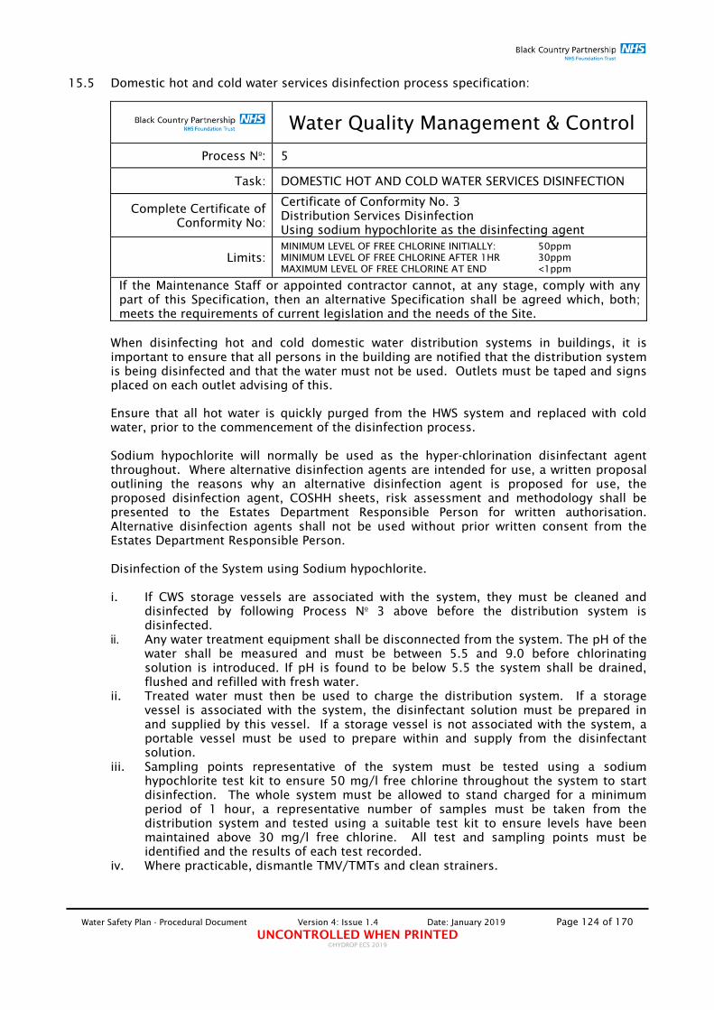
Water Safety Plan - Procedural Document Version 4: Issue 1.4 Date: January 2019 Page 124 of 170 UNCONTROLLED WHEN PRINTED
©HYDROP ECS 2019
15.5 Domestic hot and cold water services disinfection process specification:
Water Quality Management & Control
Process No: 5
Task: DOMESTIC HOT AND COLD WATER SERVICES DISINFECTION
Complete Certificate of Conformity No:
Certificate of Conformity No. 3 Distribution Services Disinfection Using sodium hypochlorite as the disinfecting agent
Limits: MINIMUM LEVEL OF FREE CHLORINE INITIALLY: 50ppm MINIMUM LEVEL OF FREE CHLORINE AFTER 1HR 30ppm MAXIMUM LEVEL OF FREE CHLORINE AT END <1ppm
If the Maintenance Staff or appointed contractor cannot, at any stage, comply with any part of this Specification, then an alternative Specification shall be agreed which, both; meets the requirements of current legislation and the needs of the Site.
When disinfecting hot and cold domestic water distribution systems in buildings, it is important to ensure that all persons in the building are notified that the distribution system is being disinfected and that the water must not be used. Outlets must be taped and signs placed on each outlet advising of this. Ensure that all hot water is quickly purged from the HWS system and replaced with cold water, prior to the commencement of the disinfection process. Sodium hypochlorite will normally be used as the hyper-chlorination disinfectant agent throughout. Where alternative disinfection agents are intended for use, a written proposal outlining the reasons why an alternative disinfection agent is proposed for use, the proposed disinfection agent, COSHH sheets, risk assessment and methodology shall be presented to the Estates Department Responsible Person for written authorisation. Alternative disinfection agents shall not be used without prior written consent from the Estates Department Responsible Person. Disinfection of the System using Sodium hypochlorite. i. If CWS storage vessels are associated with the system, they must be cleaned and
disinfected by following Process No 3 above before the distribution system is disinfected.
ii. Any water treatment equipment shall be disconnected from the system. The pH of the water shall be measured and must be between 5.5 and 9.0 before chlorinating solution is introduced. If pH is found to be below 5.5 the system shall be drained, flushed and refilled with fresh water.
ii. Treated water must then be used to charge the distribution system. If a storage vessel is associated with the system, the disinfectant solution must be prepared in and supplied by this vessel. If a storage vessel is not associated with the system, a portable vessel must be used to prepare within and supply from the disinfectant solution.
iii. Sampling points representative of the system must be tested using a sodium hypochlorite test kit to ensure 50 mg/l free chlorine throughout the system to start disinfection. The whole system must be allowed to stand charged for a minimum period of 1 hour, a representative number of samples must be taken from the distribution system and tested using a suitable test kit to ensure levels have been maintained above 30 mg/l free chlorine. All test and sampling points must be identified and the results of each test recorded.
iv. Where practicable, dismantle TMV/TMTs and clean strainers.

Water Safety Plan - Procedural Document Version 4: Issue 1.4 Date: January 2019 Page 125 of 170 UNCONTROLLED WHEN PRINTED
©HYDROP ECS 2019
v. The system shall be thoroughly flushed out with clean mains water until tests indicate that the residual free chlorine concentration is no greater than 0.5ppm mg/l that present in the mains water supply or within the dosing limits where chlorine dioxide is dosed as an on-line biocide.
vi. As described in Process No. 1 'Microbiological sample collection protocol, collect a water sample and submit for biological analysis. The analysis must measure the presence of contamination by general bacteria Total Viable Colony Count – T.V.C.C., (Legionella high risk areas). Samples to be collected no earlier than 48 hours following installation.
Neutralisation: Normally, sodium hypochlorite solutions do not require neutralisation prior to disposal to foul sewer. However, if local conditions require it, 50 mg/l disinfectant solutions can be neutralised before disposal with sodium bisulphite (SB) or sodium thiosulphate (ST) at the rate of 350 gm SB/m3 or 525 gm ST/m3 of disinfectant solution.

Water Safety Plan - Procedural Document Version 4: Issue 1.4 Date: January 2019 Page 126 of 170 UNCONTROLLED WHEN PRINTED
©HYDROP ECS 2019
15.6 Calorifier Pasteurisation:
Water Quality Management & Control
Process No. 6
Task: Calorifier Pasteurisation
Complete Certificate of Conformity No:
Certificate of Conformity No. 4 Calorifier Pasteurisation
Limits: STORED WATER TEMPERATURE: ≥70oC RETENTION TIME: 1hr Minimum
If the Maintenance Staff or appointed contractor cannot, at any stage, comply with any part of this Specification, then an alternative Specification shall be agreed which, both; meets the requirements of current legislation and the needs of the Site.
i. Purge Calorifier via drain point and refill. ii. Isolate all valves on the incoming and outlet sides. iii. Ensure that the “blow” valve is capable of withstanding temperatures of up to 80oC. iv. Bring Calorifier to 70oC (if practicable) and allow to stand at this temperature for at
least 1 hour. v. Where 70oC cannot be achieved, the calorifier shall be brought to 60oC and allow to
stand at this temperature for at least 2 hours. vi. Ensure that no water is drawn from the Calorifier whilst pasteurisation in progress. vii. Allow Calorifier to reach its normal operating temperature, 60oC, and return to
service. viii. As described in Process No. 1 'Microbiological sample collection protocol, collect a
water sample and submit for biological analysis. The analysis must measure the presence of contamination by general bacteria Total Viable Colony Count – T.V.C.C., (Legionella high risk areas). Samples to be collected no earlier than 48 hours following installation.

Water Safety Plan - Procedural Document Version 4: Issue 1.4 Date: January 2019 Page 127 of 170 UNCONTROLLED WHEN PRINTED
©HYDROP ECS 2019
15.7 Domestic water HWS distribution system pasteurisation:
Water Quality Management & Control
Process No. 7
Task: Domestic Water HWS distribution system pasteurisation
Complete Certificate of Conformity No:
Certificate of Conformity No. 5 Domestic Water HWS Distribution System Pasteurisation
Limits: STORED WATER TEMPERATURE: ≥70oC RETENTION TIME: 1hr Minimum
Note: This process must only be carried in systems which are empty of users or where the risk of scalding has been assessed, in accordance with the Trust's Risk Assessment Process, and determined to be low.
If the Maintenance Staff or appointed contractor cannot, at any stage, comply with any part of this Specification, then an alternative Specification shall be agreed which, both; meets the requirements of current legislation and the needs of the Site.
i. Purge Calorifier via drain point and refill. ii. Isolate all valves on the incoming and outlet sides. iii. Ensure that the “blow” valve is capable of withstanding temperatures of up to 80oC. iv. Bring Calorifier to 70oC (if practicable) and allow to stand at this temperature for at
least 1 hour. v. Where 70oC cannot be achieved, the calorifier shall be brought to 60oC and allow to
stand at this temperature for at least 2 hours. vi. Ensure that no water is drawn from the Calorifier whilst pasteurisation in progress. vii. Whilst maintaining the Calorifier temperature at "pasteurising temperature" open all
isolation valves to allow water from the calorifier to distribute adequately throughout all parts of the system, checking at 15 minute intervals that the temperature at sentinel outlets is maintained at "pasteurising temperature".
viii. Maintain temperature throughout the system at "pasteurising temperature" and for 1 hour if at 70oC or 2 hours if at 60oC.
ix. Allow Calorifier and distribution system to reach its normal operating temperature, 60oC, and return to service.
x. Following completion of the pasteurisation process, all TMV/TMT strainers and all other strainers, aerators and flow straighteners must be removed, cleaned and disinfected and replaced/renewed.
xi. As described in Process No. 1 'Microbiological sample collection protocol, collect a water sample and submit for biological analysis. The analysis must measure the presence of contamination by general bacteria Total Viable Colony Count – T.V.C.C., (Legionella high risk areas). Samples to be collected no earlier than 48 hours following installation.

Water Safety Plan - Procedural Document Version 4: Issue 1.4 Date: January 2019 Page 128 of 170 UNCONTROLLED WHEN PRINTED
©HYDROP ECS 2019
15.8 Point of Use (POU) filter installation and replacement:
Water Quality Management & Control
Process No: 8
Task: POINT OF USE (POU) FILTER INSTALLATION AND REPLACEMENT
Frequency: AS REQUIRED
If the Maintenance Staff or appointed contractor cannot, at any stage, comply with any part of this Specification, then an alternative Specification shall be agreed which, both; meets the requirements of current legislation and the needs of the Site.
i. Outlets to be fitted with POU filters shall be selected by the WSG and/or Infection Prevention and Control committee/representative and confirmed as described in section 8.2 "Result Interpretations and Appropriate Actions".
ii. POU filters shall be fitted by suitably and adequately trained Estates Department staff. iii. POU filters shall be replaced according to manufacturer's instructions or when there
is is a significant fall in flow-rate/pressure at the outlet indicating filter blockage. iv. OPU filters must not be replaced once removed and must be replace with new. v. POU filters, when installed and/or replaced must be dated and signed for a an
adequate log-book be maintained of their status.
Procedure for the installation and re-use of PALL bacterial filters Purpose: Pall State that the bacterial filter must be discarded if removed from the outlet, if re-used PALL will not guarantee the performance for the filter. This procedure ensures the performance of the filter following removal and refitting.
Step 1: Procedure following a Positive Presumptive P. aeruginosa sample. i. Remove outlet, TMV and associated pipe work. ii. Chlorinate at 50ppm for at least 1 hour. iii. Reinstall and fit NEW PALL adaptor and bacterial filter.
Step 2: Procedure for taking post 48Hr resample.
i. With clean hands and/or use of latex gloves, remove PALL bacterial filter and adaptor.
ii. Clean around the outlet with anti bacterial wipe and take ‘post flush’ water sample from the unfiltered outlet.
iii. Replace the filter and adaptor. iv. Take a second ‘pre flush’ water sample from the outlet of the bacterial filter. v. Take both samples to be tested ensuring each sample is clearly labelled
Filter/Unfiltered, Post/Pre flush as necessary.
Taking the filtered sample will ensure the performance of the bacterial filter following removal and refitting
Result: If both filtered and unfiltered sample return a negative result then the outlet can be returned to normal service.
If the filtered sample is negative but the unfiltered is positive then repeat step 1 ensuring a new filter is fitted. If both filtered and unfiltered sample return a positive sample then again repeat step 1 ensuring a new filter is fitted.
Note: This procedure only relates to the PALL type bacterial filters.

Water Safety Plan - Procedural Document Version 4: Issue 1.4 Date: January 2019 Page 129 of 170 UNCONTROLLED WHEN PRINTED
©HYDROP ECS 2019
15.9 Dead Legs/Areas of infrequent use – Usage evaluation and Flushing rationale:
Water Quality Management & Control
Process No: 9
Task: Dead Legs/Areas of Infrequent Use - Usage Evaluation & Flushing Rational
Usage Evaluation Frequency: MONTHLY
Flushing Frequency: 2 X WEEKLY
Systems or individual outlets that are not frequently used allow the development of stagnant water conditions, which increase the potential of bacterial growth and proliferation, including Legionella. In order to remove any stagnation that may have developed or to stop stagnation from occurring in the first place, it is important to introduce a "flushing" programme where necessary. Departmental Heads shall have the responsibility to ensure that this requirement is implemented and systematically audited to ensure adequate and correct implementation. The flushing programme shall be designed so that it allows for the whole dead-leg to be removed. This is achieved by ensuring that the flushing is carried out at the specified system or outlet and for an appropriate length of time. The length of time of purging water from the system is important because it is vital to ensure that all the stagnant water has been expelled from the pipe-work and at least until "circulating" or "fresh" water is drawn from the outlet (water at temperatures exhibited throughout the rest of the system). The flushing programme shall follow the procedure outlined below: A. For all areas which are in "normal operating use", the responsibility for the Usage
Evaluation and Flushing process shall be that of the "user". B. For all areas which are "out of use", the responsibility for the Usage Evaluation and
Flushing process shall be that of the Estates Department. i. Carry out the Monthly “Usage Evaluation” process in order to identify areas/outlets which
are not used at least 2 x weekly so that they can be flushed. ii. Ensure that the system/outlet can be flushed safely and in a tidy manner into an
appropriate drain if not plumbed for drainage. iii. Ensure that the purging of water from outlets does not create an unnecessary amount
of aerosol at least no more than would be created when outlet is operated normally. iv. Ensure that "splash-back" is minimised, where practicable, by placing a sponge or
another material capable of absorbing some of the force of the water against the surface of the appliance.
v. Purge the hot and the cold or the mixed water in turn for a minimum of 3 minutes or for a period of time necessary to draw water from the outlet at temperatures exhibited throughout the rest of the system.
vi. Where showers need to be flushed, it is important to ensure that, where practicable, the shower-head is removed in order to reduce the potential of aerosol production. Where the head is fixed, exposure to the aerosol produced must be minimised. One method that can be employed in this situation is the use of a transparent plastic bag, fixed around the shower- head, with one corner pierced to allow partial discharge of water.
vii. Consider whether the system/outlet can be removed negating further flushing. viii. Report the process via the Trust's 'Usage Evaluation and Flushing' reporting process.

Water Safety Plan - Procedural Document Version 4: Issue 1.4 Date: January 2019 Page 130 of 170 UNCONTROLLED WHEN PRINTED
©HYDROP ECS 2019
15.10 Dead Legs/Areas of Infrequent Use – Usage Evaluation and Flushing Reporting Process:
Water Quality Management & Control
Process No: 10
Task: Dead Legs/Areas of Infrequent Use - Usage Evaluation & Flushing Reporting Process
Usage Evaluation Frequency: MONTHLY
Flushing Frequency: 2 X WEEKLY
Ward/Department management appointed staff shall have the responsibility of identifying all infrequently used outlets within their area, on a Monthly basis and subjecting these to a prescribed flushing programme. This process is depicted by the flow chart shown below. Reporting of the Usage Evaluation and Flushing process shall be carried out in accordance with the process described below: 1. Carry out the Usage Evaluation on a Monthly basis. 2. Carry out the flushing of all identified infrequently used outlets and on a 2 x weekly
basis. 2. Indicate when areas are to lie vacant for more than 4 days. This will allow the Estates
Department to liaise with relevant departments and agree the necessary precautions. 3. Where infrequently used facilities are deemed by the ward/department staff to be no
longer required, they must be notified to the Estates Department, who, following adequate authorisation from IPC, will arrange for their isolation or removal.
PPM Tasks scheduled by
Data immediately and automatically uploaded, real-
time onto COMPASS and results analysed and
automatically prioritised onto a 'defect-log' detailing remedial work required and rectification works automatically assigned
Designated hospital personnel immediately and automatically notified of fresh uploaded PPM
task data. Access at http://www.hydrop.com/login/
Estates Manager reviews 'Defect-Log' an manages
identified defects by raising appropriate corrective 'Works
Orders'
Uploaded fresh data into
COMPASS used to generate
updated Risk Assessment
“Usage Evaluation and Flushing” process carried out by Estates and Ward Staff 2 x Weekly and
reported using COMPASS 'Usage Evaluation & Flushing' process
'Task Completed'
data received within
scheduled time period
and automatically uploaded onto
COMPASS
'Failure to complete task' notification escalated to IPC, Head of Estates & Technical services and
WSG Chair
'Task Completed' data NOT received within
scheduled time period
and automatically uploaded onto
COMPASS

Water Safety Plan - Procedural Document Version 4: Issue 1.4 Date: January 2019 Page 131 of 170 UNCONTROLLED WHEN PRINTED
©HYDROP ECS 2019
"Escalation Notification" process of failures of the Usage Evaluation and Flushing Programme:
No. of Consecutive Completion misses Notification Contacts
<3
Individual; Matron; Estates Department
3
All the above plus; DGM; Clinical Director; Consultant Microbiologist
>3 All the above Plus; Chief Nurse

Water Safety Plan - Procedural Document Version 4: Issue 1.4 Date: January 2019 Page 132 of 170 UNCONTROLLED WHEN PRINTED
©HYDROP ECS 2019
15.11 Management of Drinking Fountains:
Water Quality Management & Control
Process No: 11
Task: Management of Drinking Fountains
Frequency: AS REQUIRED
Note: The use of Bottle Water Dispensers shall not be allowed.
Request to install new drinking fountain i. In order to ensure that infection prevention and control is assured, all new drinking
fountains shall only be installed upon written authorisation from the WSG/Responsible Person (Estates) who may issue such authorisation following receipt of a detailed written request.
ii. No drinking fountains shall be installed without written authorisation from the WSG/Responsible Person (Estates).
iii. Any new drinking fountains fitted without the appropriate authorisation for its installation, shall be removed by the Responsible Person (Estates).
Guidance on the selection of drinking fountains i. Units selected must be WRAS approved and suitably approved by all relevant bodies
for the use in a healthcare environment. ii. In order to avoid stagnation and resultant potential increase in bacterial growth and
proliferation within the unit, it is preferable that the unit selected does not have a water storage tank.
iii. In order to maximise bacterial growth and proliferation control, it is preferable that the unit selected does have UV bacterial control.
iv. In order to reduce the potential of bacterial growth and proliferation on the spout caused by the collection of scale and other debris deposits, it is preferable that the unit selected has the facility to replace the spout.
v. In order to reduce the potential of bacterial growth and proliferation and the build-up of biofilm in the supply connections to the unit, it is important that the unit does not require connection using EPDM flexible hose connectors as these have been shown to promote bacterial growth and proliferation and support the development of biofilm locally.
vi. In order to reduce the potential of bacterial growth and proliferation and the build-up of biofilm in the supply connections to the unit, it is important that the unit does not incorporate EPDM seals/gaskets as these have been shown to promote bacterial growth and proliferation and support the development of biofilm locally.
Installation i. All drinking fountains must be installed by suitably qualified contractors and in
accordance with all Water Regulations requirements and the requirements of this WSP.
ii. All drinking fountains must be installed in a proper manner and connected onto a potable water supply.
iii. All drinking fountains must be suitably disinfected in accordance with manufacturer's instructions.

Water Safety Plan - Procedural Document Version 4: Issue 1.4 Date: January 2019 Page 133 of 170 UNCONTROLLED WHEN PRINTED
©HYDROP ECS 2019
iv. All drinking fountains must be sampled, in accordance to the Sample Collection methodology detailed below.
v. All drinking fountains must indicate Maintenance i. All drinking fountains shall be subject to a suitable contract to ensure maintenance in
accordance with manufacturers' instructions. All contracts shall be subject to approval by the Responsible Person (Estates).
ii. Any drinking fountains found in use without a suitably approved maintenance contract shall be taken out of use, by the Responsible Person Estates, until the unit is placed under a contract.
Microbiological Screening i. Subject to instructions from the WSG selected drinking fountains must be subject to a
monthly microbiological screening programme for the presence of E. coli, coliforms and P. aeruginosa.
ii. All microbiological samples must be collected in accordance with Process No. 1 'Microbiological Sample Collection Protocol'.
Where practicable, separate drinking water systems shall be provided directly from the town main or site main (from break-tanks) without local storage. Otherwise, all supplies to drinking water systems shall be of potable quality. The supply shall not be softened to less than 70ppm of total hardness. Chlorite and chlorate in the drinking water does not exceed 0.5 mg/l as chlorine dioxide. Additionally, it shall be established that the usage is sufficient to avoid deterioration in water quality, for example, that the inlet water temperature does not exceed 20OC and that the outlet does not remain unused.

Water Safety Plan - Procedural Document Version 4: Issue 1.4 Date: January 2019 Page 134 of 170 UNCONTROLLED WHEN PRINTED
©HYDROP ECS 2019
15.12 Notification of Closure of Facility:
Water Quality Management & Control
Process No: 12
Task: Notification of Closure of Facility (Facility refers to; a ward, part of a ward, a room within a ward, a section of a building etc.)
Frequency: AS REQUIRED
Closure Notification of facility If a facility is to be closed, it is the responsibility of the facility manager to notify of the impending facility closure by submitting a completed copy of Section 1 of Permit No. 4 'Notification of Closure of Facility and Permit to Re-occupy' to the Responsible Person (Estates) at least one week (where practicable) prior to the Facility closure. Temporary Closures (Closures of less than one month) where no modifications, alterations and/or refurbishments are planned During the temporary closure of a facility, where no major modifications, alterations and/or refurbishments are planned, a procedure for flushing hot and cold water systems shall be instituted by the Responsible Person (Estates) in accordance with Process No. 9 'Dead legs/Areas of Low Usage Evaluation and Flushing'. This process shall be implemented and its implementation recorded by the completion of Section 4 of Permit No. 4 'Notification of Closure of Facility and Permit to Re-occupy' by the Responsible Person (Estates). Disinfection of the domestic water services would not be required before re-occupation under these circumstances. Microbiological sampling of the domestic water services would also not be required unless expressly requested by the Trust's Consultant Microbiologist. It is important, however, to ensure that the temperature levels are within acceptable levels before re-occupation can be permitted. Re-occupation shall be subject to the appropriate authorisation Section 8 of Permit No. 4 'Notification of Closure of Facility and Permit to Re-occupy' signed by the Trust's Consultant Microbiologist. Long-term Closures (Closures of more than one month) where no modifications, alterations and/or refurbishments are planned During the long-term closure of the facility for more than one month, the system, where practicable, shall be isolated from the domestic hot and cold supplies and drained. This process shall be implemented and its implementation recorded by the completion of Section 5 of Permit No. 4 'Notification of Closure of Section/Area' by the Responsible Person (Estates). Disinfection of the domestic water services would be required before re-occupation under these circumstances and this must be carried out in accordance with Process No. 5 'Domestic Water Services Disinfection'. Microbiological sampling of the domestic water services would also be required and this must be carried out in accordance with Process No. 1 'Microbiological Sample Collection Protocol'. It is also important to ensure that the temperature levels are within acceptable levels before re-occupation can be permitted.

Water Safety Plan - Procedural Document Version 4: Issue 1.4 Date: January 2019 Page 135 of 170 UNCONTROLLED WHEN PRINTED
©HYDROP ECS 2019
Re-occupation shall be subject to the appropriate authorisation Section 8 of Permit No. 4 'Notification of Closure of Facility and Permit to Re-occupy' signed by the Trust's Consultant Microbiologist. Where the system cannot be isolated and drained, the process described in 9.12.2 shall be followed. Closures where minor-works are planned If the facility is subject to minor works projects (small sized pipework and associated components installations) it is the responsibility of the Responsible Person (Estates) to ensure that the appropriate actions are taken in accordance with Process No. 2 'Small sized pipework installation projects and associated components pre and post installation cleaning and disinfection'. This process shall be implemented and its implementation recorded by the completion of Section 7 of Permit No. 4 'Notification of Closure of Facility and Permit to Re-occupy'' by the Responsible Person (Estates). Disinfection of the domestic distribution water services would not be required before re-occupation under these circumstances. Microbiological sampling of the domestic water services would also not be required unless expressly requested by the Trust's Consultant Microbiologist. It is important, however, to ensure that the temperature levels are within acceptable levels before re-occupation can be permitted. Re-occupation shall be subject to the appropriate authorisation Permit No. 3 'Permit for Release into Use of new installations of small sized pipework installation projects and associated components' signed by the appropriate Responsible Person. Permit No. 3 must be accompanied by the completed Section 8 of Permit No. 4 'Notification of Closure of Facility and Permit to Re-occupy' signed by the Trust's Consultant Microbiologist. Closures where major works are planned If the facility is subject to major works including modifications/refurbishments, it is the responsibility of the Project Manager to ensure implement and record this process by the completion of Section 7 of Permit No. 4 'Notification of Closure of Facility and Permit to Re-occupy'. Disinfection of the domestic water services would be required before re-occupation under these circumstances and this must be carried out in accordance with Process No. 5 'Domestic Water Services Disinfection'. Microbiological sampling of the domestic water services would also be required and this must be carried out in accordance with Process No. 1 Microbiological Sample Collection Protocol. It is also important to ensure that the temperature levels are within acceptable levels before re-occupation can be permitted. Re-occupation shall be subject to the appropriate authorisation Permit No. 6 'Permit for Hand-over and occupation of refurbished facilities' signed by the Trust's Consultant Microbiologist.

Water Safety Plan - Procedural Document Version 4: Issue 1.4 Date: January 2019 Page 136 of 170 UNCONTROLLED WHEN PRINTED
©HYDROP ECS 2019
15.13 Patient Susceptibility Risk Categorisation Assessment:
Water Quality Management & Control
Process No: 13
Task: Patient Susceptibility Risk Categorisation Assessment
Frequency: AS REQUIRED
In order that the appropriate Legionellosis risk management measures are employed correctly, the Infection Prevention and Control Lead Nurse (IPCN) and the matron responsible for each area, shall assess patient susceptibility to Legionellosis in all clinical areas, by completing this pro-forma and confirm to the WSG their assessed risk categorisation. The assessed risk must be considered when managing patients in the event of reported Legionella contamination in the system and when compiling the Legionella Risk Assessment and shall be the driving force behind the development of specific and pertinent risk management strategies for each clinical area.
Location Ward:
Parameter Weight Risk Points
Age group
<50 years 1 50-59 years 2 60-69 years 3 >70 years 4
Gender Male 2 Female 1
Lifestyle Smoker 2 Alcohol associated problems 2
Current Medical History
Neutropenic 10 Respiratory condition 6 Diabetes 4 Renal disorder 3 Heart Disease 3 Liver condition 1 *Aspiration risk *Only when associated with one of the conditions listed above 5
Medication
Antibiotics within the last 2 weeks 3 High dose Steroid 40mg per day for 1 week 5 Immunosuppressive therapy(chemo/radio) 10 Bone marrow transplant (up to 12 months post) 10 Solid organ transplant drugs 10
OVERALL RISK SCORE
Overall Risk Score Assessed Risk
0 - 8 LOW
9 - 10 MODERATE
11 - 14 HIGH
>15 URGENT
Additional Notes:
Assessment Carried out by:
Date
When completed, this pro-forma must be submitted to the Responsible Person (Estates) for filing.

Water Safety Plan - Procedural Document Version 4: Issue 1.4 Date: January 2019 Page 137 of 170 UNCONTROLLED WHEN PRINTED
©HYDROP ECS 2019
15.14 Risk Assessment Status Enquiry pro-forma:
Water Quality Management & Control
Process No: 14
Task: Risk Assessment Status Enquiry
Frequency: 6-MONTHLY
Facility:
System:
Date of most recent risk assessment:
Risk Assessment ref. No.
The status of each assessment shall be reviewed by the Responsible Person (Estates), with assistance from IPC, on a 6-MONTHLY basis and instructions given to the WSG to commission a new risk assessment whenever there is reason to believe that the original assessment may no longer be valid or in accordance with the schedule detailed in the table below:
Query Comments Has there been a significant change to the plant or water or its use?
Has there been a significant change to the use of the building in which the system is installed?
Has there been a significant change to related guidance regarding risks or control measures?
Has there been a significant change to key personnel?
Have sample results indicated that the control measures are no longer effective?
Additional Notes
Date of review:
Review conducted by:
Name Signature
Next Process required: New risk assessment Review most current risk
assessment in 6-Months
Date of this review:
Date of next review:
The results of this exercise shall be formally reported to the WSG at the next scheduled meeting. When completed, this proforma must be appropriately filed by the Responsible Person (Estates).
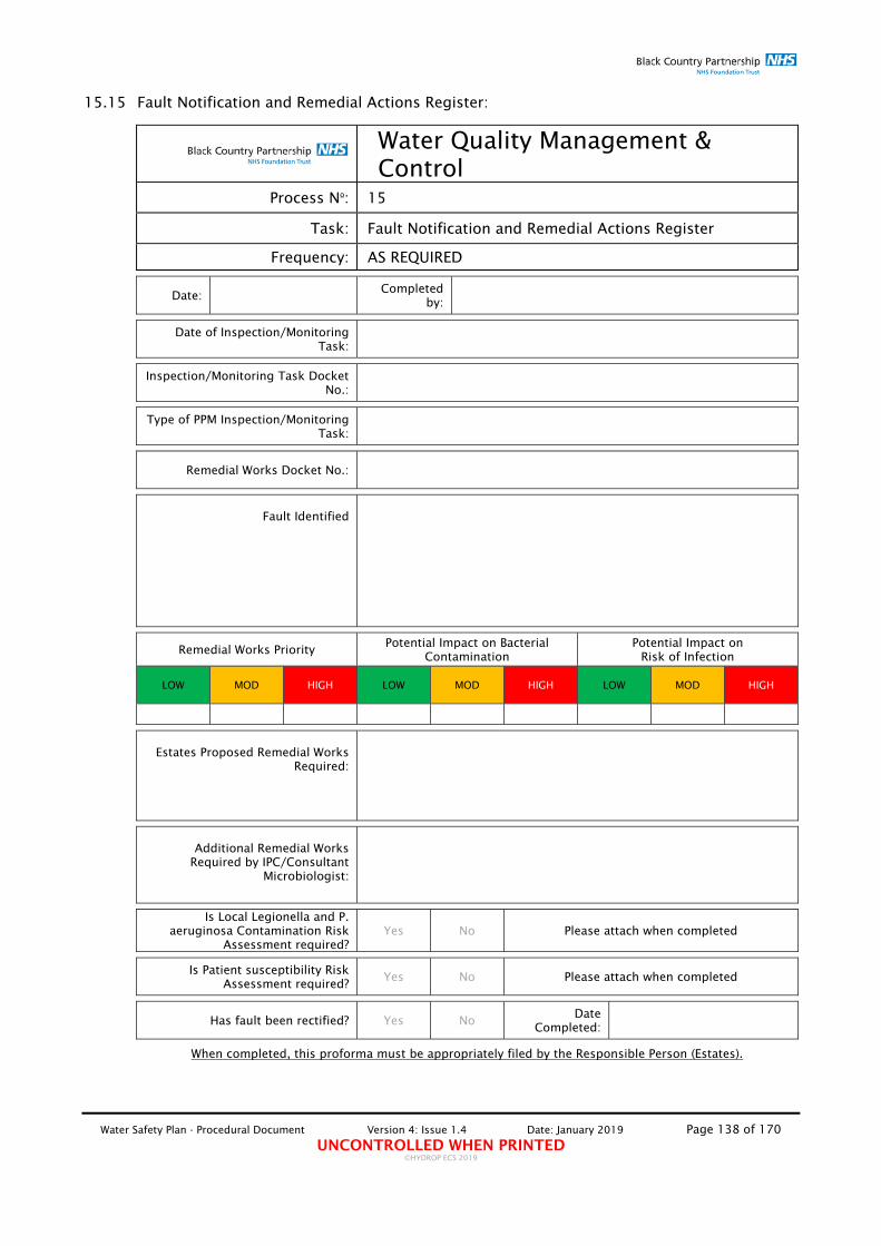
Water Safety Plan - Procedural Document Version 4: Issue 1.4 Date: January 2019 Page 138 of 170 UNCONTROLLED WHEN PRINTED
©HYDROP ECS 2019
15.15 Fault Notification and Remedial Actions Register:
Water Quality Management & Control
Process No: 15
Task: Fault Notification and Remedial Actions Register
Frequency: AS REQUIRED
Date: Completed
by:
Date of Inspection/Monitoring Task:
Inspection/Monitoring Task Docket No.:
Type of PPM Inspection/Monitoring Task:
Remedial Works Docket No.:
Fault Identified
Remedial Works Priority Potential Impact on Bacterial
Contamination Potential Impact on
Risk of Infection
LOW MOD HIGH LOW MOD HIGH LOW MOD HIGH
Estates Proposed Remedial Works
Required:
Additional Remedial Works
Required by IPC/Consultant Microbiologist:
Is Local Legionella and P. aeruginosa Contamination Risk
Assessment required? Yes No Please attach when completed
Is Patient susceptibility Risk Assessment required?
Yes No Please attach when completed
Has fault been rectified? Yes No Date
Completed:
When completed, this proforma must be appropriately filed by the Responsible Person (Estates).
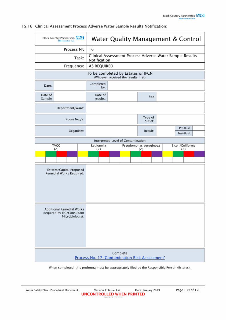
Water Safety Plan - Procedural Document Version 4: Issue 1.4 Date: January 2019 Page 139 of 170 UNCONTROLLED WHEN PRINTED
©HYDROP ECS 2019
15.16 Clinical Assessment Process Adverse Water Sample Results Notification:
Water Quality Management & Control
Process No: 16
Task: Clinical Assessment Process Adverse Water Sample Results Notification
Frequency: AS REQUIRED
To be completed by Estates or IPCN (Whoever received the results first)
Date: Completed
by:
Date of Sample
Date of results:
Site
Department/Ward:
Room No./s: Type of outlet:
Organism: Result: Pre-flush
Post-flush
Interpreted Level of Contamination
TVCC ()
Legionella ()
Pseudomonas aeruginosa ()
E coli/Coliforms ()
Estates/Capital Proposed
Remedial Works Required:
Additional Remedial Works
Required by IPC/Consultant Microbiologist:
Complete Process No. 17 ‘Contamination Risk Assessment'
When completed, this proforma must be appropriately filed by the Responsible Person (Estates).

Water Safety Plan - Procedural Document Version 4: Issue 1.4 Date: January 2019 Page 140 of 170 UNCONTROLLED WHEN PRINTED
©HYDROP ECS 2019
15.17 Contamination Risk Assessment:
Water Quality Management & Control
Process No: 17
Task: Contamination Risk Assessment – To be carried out within 24hrs of notification of contamination
Frequency: AS REQUIRED PLEASE NOTE: ALSO COMPLETE THE ‘WATER MANAGEMENT CLINICAL RISK ASSESSMENT’ – SEE BELOW
The purpose of the Local Risk Assessment is to carry out a detailed coordinated assessment of the patients, staff, environment and water system in an area where a "Significant" or "Highly Significant" Legionella or Pseudomonas aeruginosa biological sample analysis result has indicated that there may be a problem. The Risk Assessment shall consider the maintenance records for the area, flushing records and also investigate the water systems in the area to identify the underlying cause of the problems and set out the remedial action necessary to address the threat. In addition an assessment of the patients shall be carried out so that appropriate measures are taken to protect any patients that may be considered to be susceptible to infection.
Outlet Asset No. Location:
Date of risk assessment:
Carried out by:
Date:
Parameter Risk
Weight Points
Scored
A. System Contamination
Legionella pneumophila. @<100cfu/l 1
Legionella sp. @>100 - <1000cfu/l 2
Legionella sp. @>1000cfu/l 3
A: Sub Total 6
B. Patient Susceptibility
Age group >50 years 1 Lifestyle Smoker/Alcohol related problems 1
Current Medical History
Neutropenic 3 Respiratory condition, Diabetes, Renal disorder, Heart Disease, Liver condition 2
Medication
Antibiotics within the last 2 weeks, High dose Steroid 40mg per day for 1 week 1
Immunosuppressive therapy/Bone marrow transplant/ Solid organ transplant 2
B: Sub Total 10
C. System/Operational Conditions
Infrequently used outlet 1
Presence of local dead-legs 1
Scale and/or dirt on outlet aerator and/or flow straightener 1
Scale and/or dirt on the TMV/TMT strainer 1
Water temperatures/on-line disinfectant outside of control limits 1
Lack of proper hand wash basins assignment 1
Evidence of improper use of hand wash basin 1
Evidence of poor cleaning practices 1
C: Sub Total 8
D. Managed Mitigation
None 3
POU filter adequately fitted to outlet but remains in-use 2
Patient removed/outlet isolated and continued to be flushed 1
D: Sub Total
Total: A x B x C x D

Water Safety Plan - Procedural Document Version 4: Issue 1.4 Date: January 2019 Page 141 of 170 UNCONTROLLED WHEN PRINTED
©HYDROP ECS 2019
Additional Comments
Overall Risk Score Assessed Risk Actions
0 NONE Review local risk assessment when need arises
1 - 15 LOW Continue to monitor system and manage patient with care plan
16 - 35 MODERATE Investigate and correct system failures. Continue to monitor with care plan and contact Infection Control Team to allow for closer monitoring of patient
30 - 65 HIGH
Investigate and correct system failures. Ensure correct patient management under notification of Pseudomonas aeruginosa/Legionella contamination locally or systemically. Continue to monitor patient with care plan. Contact infection control team. Consider relocation of patient.
>65 URGENT Ensure that the patient is not exposed to the domestic water system unless the outlets accessible to the patient are fitted with Point-of-Use filters. Continue to monitor patient with care plan. Contact infection control team and raise at MDT review. Relocate patient
Agreed Actions
Completed BY: Name:............................................................Signature:..........................Date:......................... Name:............................................................Signature:..........................Date:......................... Name:............................................................Signature:..........................Date:......................... Name:............................................................Signature:..........................Date:.........................
When completed, this proforma must be appropriately filed by the Responsible Person (Estates)

Water Safety Plan - Procedural Document Version 4: Issue 1.4 Date: January 2019 Page 142 of 170 UNCONTROLLED WHEN PRINTED
©HYDROP ECS 2019
15.18 Management of Water Dispensers/Water Coolers:
Water Quality Management & Control
Process No: 18
Task: Management of Water Dispensers/Water Coolers
Frequency: AS REQUIRED
If the Maintenance Staff or appointed contractor cannot, at any stage, comply with any part of this Specification, then an alternative Specification shall be agreed which, both; meets the requirements of current legislation and the needs of the Site.
Note: The use of Bottle Water Dispensers shall not be allowed.
Request to install new Water Dispenser/Water Cooler i. In order to ensure that infection prevention and control is assured, all new Water
Dispenser/Water Cooler shall only be installed upon written authorisation from the WSG/Responsible Person (Estates) who may issue such authorisation following receipt of a detailed written request.
ii. No Water Dispenser/Water Cooler shall be installed without written authorisation from the WSG/Responsible Person (Estates).
iii. Any new Water Dispenser/Water Cooler fitted without the appropriate authorisation for its installation, shall be removed by the Responsible Person (Estates).
Guidance on the selection of Water Dispensers/Water Coolers i. Units selected must be WRAS approved and suitably approved by all relevant bodies
for the use in a healthcare environment. ii. In order to avoid stagnation and resultant potential increase in bacterial growth and
proliferation within the unit, it is preferable that the unit selected does not have a water storage tank.
iii. In order to maximise bacterial growth and proliferation control, it is preferable that the unit selected does have UV bacterial control.
iv. In order to reduce the potential of bacterial growth and proliferation on the spout caused by the collection of scale and other debris deposits, it is preferable that the unit selected has the facility to replace the spout.
v. In order to reduce the potential of bacterial growth and proliferation and the build-up of biofilm in the supply connections to the unit, it is important that the unit does not require connection using EPDM flexible hose connectors as these have been shown to promote bacterial growth and proliferation and support the development of biofilm locally.
vi. In order to reduce the potential of bacterial growth and proliferation and the build-up of biofilm in the supply connections to the unit, it is important that the unit does not incorporate EPDM seals/gaskets as these have been shown to promote bacterial growth and proliferation and support the development of biofilm locally.
Installation i. All Water Dispensers/Water Coolers must be installed by suitably qualified
contractors and in accordance with all Water Regulations requirements and the requirements of this WSP.
ii. All Water Dispensers/Water Coolers must be installed in a proper manner and connected onto a potable water supply.
Water Safety Plan - Procedural Document Version 4: Issue 1.4 Date: January 2019 Page 143 of 170 UNCONTROLLED WHEN PRINTED
©HYDROP ECS 2019
iii. All Water Dispensers/Water Coolers must be suitably disinfected in accordance with manufacturer's instructions.
iv. All Water Dispensers/Water Coolers must be sampled, in accordance to the Sample Collection methodology detailed below.
v. All Water Dispensers/Water Coolers must indicate Maintenance i. All Water Dispensers/Water Coolers shall be subject to a suitable contract to ensure
maintenance in accordance with manufacturers' instructions. All contracts shall be subject to approval by the Responsible Person (Estates).
ii. Any Water Dispensers/Water Coolers found in use without a suitably approved maintenance contract shall be taken out of use, by the Responsible Person Estates, until the unit is placed under a contract.
Microbiological Screening i. Subject to instructions from the WSG selected Water Dispensers/Water Coolers must
be subject to a monthly microbiological screening programme for the presence of E. coli, coliforms and P. aeruginosa.
ii. All microbiological samples must be collected in accordance with Process No. 1 'Microbiological Sample Collection Protocol'.
Where practicable, separate drinking water systems shall be provided directly from the town main or site main (from break-tanks) without local storage. Otherwise, all supplies to drinking water systems shall be of potable quality. The supply shall not be softened to less than 70ppm of total hardness. Chlorite and chlorate in the drinking water does not exceed 0.5 mg/l as chlorine dioxide. Additionally, it shall be established that the usage is sufficient to avoid deterioration in water quality, for example, that the inlet water temperature does not exceed 20OC and that the outlet does not remain unused.

Water Safety Plan - Procedural Document Version 4: Issue 1.4 Date: January 2019 Page 144 of 170 UNCONTROLLED WHEN PRINTED
©HYDROP ECS 2019
15.19 Identification and Size Demarcation of Scope of Works:
Water Quality Management & Control
Process No: 19
Task: Identification and Size Demarcation of Scope of Works
Frequency: AS REQUIRED
THIS SECTION TO BE COMPLETED BY THE RESPONSIBLE PERSON (ESTATES)
Project/Scheme reference:
Date of commencement of Project/Scheme:
Duration:
Type of works: New built: Major refurb: *Minor works:16.
If Minor Works: >2M pipework *<2M
pipework *No new pipework
Value of works:
Brief description of works undertaken
Works carried out by:
Will works be on a 'live' system?
Yes No Which
Necessary controls been planned?
Yes No What
Disinfection required (Yes/No)? Local System Planned
(Yes/No)
Is sampling required (Yes/No)? Local System Planned
(Yes/No)
Is Risk Assessment required (Yes/No)? Local System Planned
(Yes/No)
*For Minor Works and for projects/schemes involving <2M pipework (cumulative), use: Process No. 2 - Small sized pipework installation projects and associated components disinfection/Permit No. 2 - Permit for Release into Use of new installations of small sized pipework installation projects and associated components (Note this is not required for like for like changes)
Responsible Person (Estates):
Signed: .............................................................. Date:.................

Water Safety Plan - Procedural Document Version 4: Issue 1.4 Date: January 2019 Page 145 of 170 UNCONTROLLED WHEN PRINTED
©HYDROP ECS 2019
16. APPENDIX 5 – CERTIFICATES OF CONFORMITY Certificate of Conformity No. 1: Cold Water Storage Tank Cleaning and Disinfection
Using sodium hypochlorite as the disinfecting agent – Spray method
Certificate of Conformity No. 2: Cold Water Storage Tank Cleaning and Disinfection Using sodium hypochlorite as the disinfecting agent – Soaking Method
Certificate of Conformity No. 3: Distribution Services Disinfection Using sodium hypochlorite as the disinfecting agent
Certificate of Conformity No. 4: Calorifier Pasteurisation
Certificate of Conformity No. 5: Domestic Water HWS Distribution System Pasteurisation
Certificate of Conformity No. 6: 'Certificate of Design Compliance'
Certificate of Conformity No. 7: 'Certificate of Installation Compliance'
Certificate of Conformity No. 8: 'Certificate of Flushing Process'

Water Safety Plan - Procedural Document Version 4: Issue 1.4 Date: January 2019 Page 146 of 170 UNCONTROLLED WHEN PRINTED
©HYDROP ECS 2019
16.1 Certificate of Conformity No. 1: Cold Water Storage Tank Cleaning and Disinfection:
Water Quality Management & Control Log-Book
Certificate of Conformity No. 1 Cold Water Storage Tank Cleaning and Disinfection
Using sodium hypochlorite as the disinfecting agent – Spray method
No Tasks Date Tank Asset
No. Comments Signature
1 Tank Volume:
2 Method of disinfection:
3 Disinfectant used:
4
Spray all surfaces of the tank using an adequately vented
knapsack or garden pressure sprayer or fogger, with ready
prepared 500 mg/L free chlorine solution, ensuring that all surfaces remain wet with disinfectant for at
least 10 minutes. Note the requirements for personal
protective equipment when spraying of fogging sodium
hypochlorite solutions.
5
When the spray disinfection is complete and the solution has
been in contact with all surfaces for at least 10 minutes, thoroughly
rinse all sprayed surfaces with clean water and remove any
residues with pump/wet vac or flush through to drain
6 Refill with fresh water and put
back into service. Check residual of free chlorine is below 1mg/L.
7 Water analysis carried out (Y/N):
8 Analysis results
9 Date of last disinfection:
10 Any refurbishment, improvements carried out during this disinfection:
11 Further upgrading, refurbishment,
improvements works required
This section to be completed by the Trust Responsible Person (Estates)
Signature Date of check All reported faults to be transferred to “Monthly Defect Log” for processing
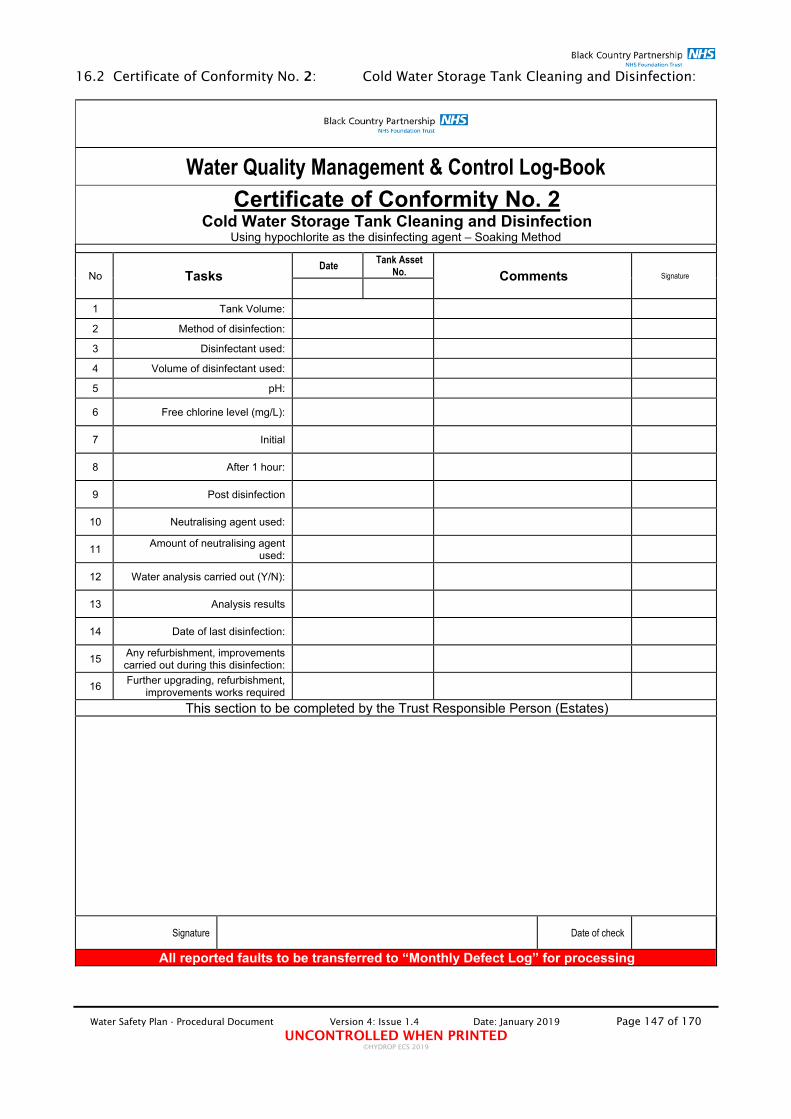
Water Safety Plan - Procedural Document Version 4: Issue 1.4 Date: January 2019 Page 147 of 170 UNCONTROLLED WHEN PRINTED
©HYDROP ECS 2019
16.2 Certificate of Conformity No. 2: Cold Water Storage Tank Cleaning and Disinfection:
Water Quality Management & Control Log-Book
Certificate of Conformity No. 2 Cold Water Storage Tank Cleaning and Disinfection
Using hypochlorite as the disinfecting agent – Soaking Method
No Tasks Date Tank Asset
No. Comments Signature
1 Tank Volume:
2 Method of disinfection:
3 Disinfectant used:
4 Volume of disinfectant used:
5 pH:
6 Free chlorine level (mg/L):
7 Initial
8 After 1 hour:
9 Post disinfection
10 Neutralising agent used:
11 Amount of neutralising agent
used:
12 Water analysis carried out (Y/N):
13 Analysis results
14 Date of last disinfection:
15 Any refurbishment, improvements carried out during this disinfection:
16 Further upgrading, refurbishment,
improvements works required
This section to be completed by the Trust Responsible Person (Estates)
Signature Date of check All reported faults to be transferred to “Monthly Defect Log” for processing
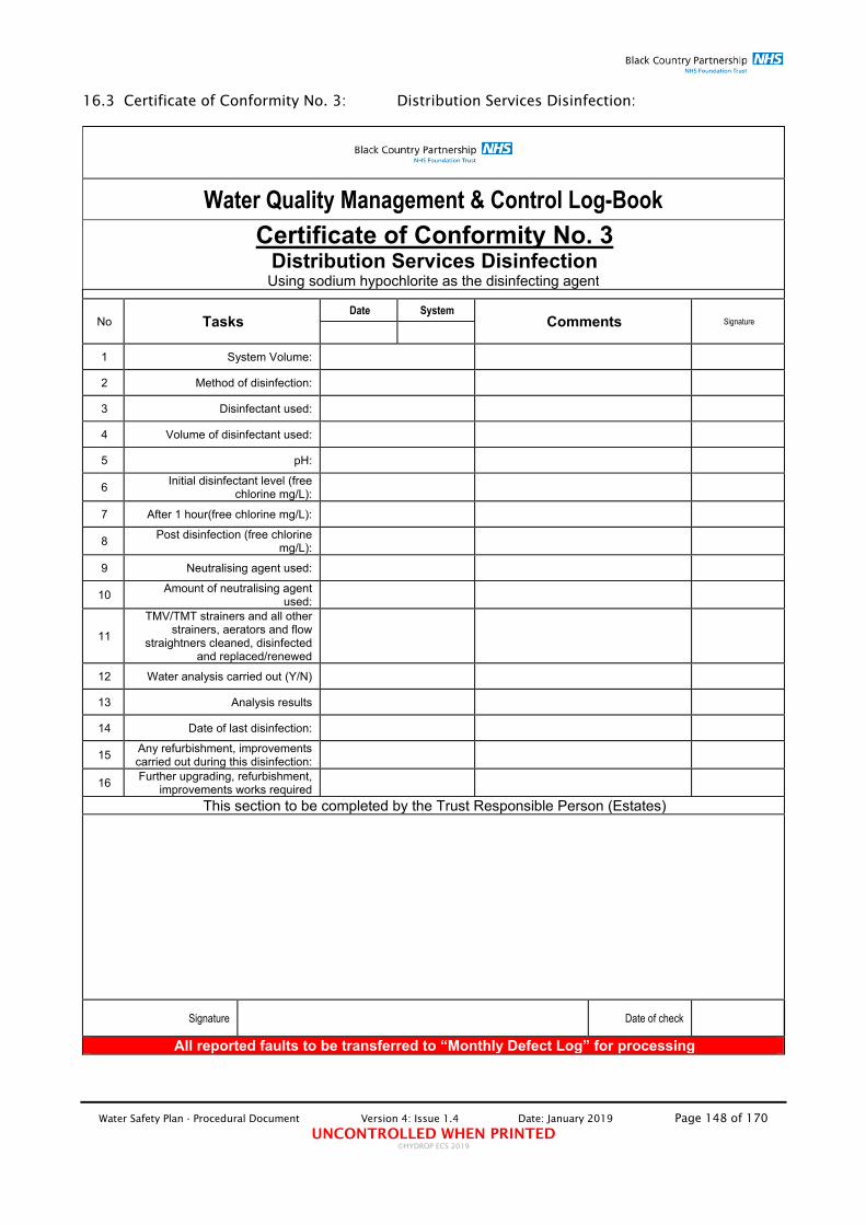
Water Safety Plan - Procedural Document Version 4: Issue 1.4 Date: January 2019 Page 148 of 170 UNCONTROLLED WHEN PRINTED
©HYDROP ECS 2019
16.3 Certificate of Conformity No. 3: Distribution Services Disinfection:
Water Quality Management & Control Log-Book
Certificate of Conformity No. 3 Distribution Services Disinfection Using sodium hypochlorite as the disinfecting agent
No Tasks Date System
Comments Signature
1 System Volume:
2 Method of disinfection:
3 Disinfectant used:
4 Volume of disinfectant used:
5 pH:
6 Initial disinfectant level (free
chlorine mg/L):
7 After 1 hour(free chlorine mg/L):
8 Post disinfection (free chlorine
mg/L):
9 Neutralising agent used:
10 Amount of neutralising agent
used:
11
TMV/TMT strainers and all other strainers, aerators and flow
straightners cleaned, disinfected and replaced/renewed
12 Water analysis carried out (Y/N)
13 Analysis results
14 Date of last disinfection:
15 Any refurbishment, improvements carried out during this disinfection:
16 Further upgrading, refurbishment,
improvements works required
This section to be completed by the Trust Responsible Person (Estates)
Signature Date of check All reported faults to be transferred to “Monthly Defect Log” for processing

Water Safety Plan - Procedural Document Version 4: Issue 1.4 Date: January 2019 Page 149 of 170 UNCONTROLLED WHEN PRINTED
©HYDROP ECS 2019
16.4 Certificate of Conformity No. 4: Calorifier Pasteurisation:
Water Quality Management & Control Log-Book
Certificate of Conformity No. 4 Calorifier Pasteurisation
No Tasks Date Calorifier
Asset No. Comments Signature
1 Unit Drain flush carried out:
2 Inlet Valve closed:
3 Outlet valve closed:
4 Circulation pumps off:
5 Shunt pump on:
6 Are there any leaks (Y/N)
7 Type of heating provided:
8 Time of beginning of process
(24hr clock):
9 Pasteurising temperature
achieved:
10 Time pasteurising temperature
kept:
11 Time of end of process (24hr
clock):
12 Water analysis carried out (Y/N)
13 Analysis results
14 Date of last disinfection:
15 Any refurbishment, improvements carried out during this disinfection:
This section to be completed by the Trust Responsible Person (Estates)
Signature Date of check All reported faults to be transferred to “Monthly Defect Log” for processing

Water Safety Plan - Procedural Document Version 4: Issue 1.4 Date: January 2019 Page 150 of 170 UNCONTROLLED WHEN PRINTED
©HYDROP ECS 2019
16.5 Certificate of Conformity No. 5: Domestic Water HWS Distribution System
Pasteurisation:
Water Quality Management & Control Log-Book
Certificate of Conformity No. 5 Domestic Water HWS Distribution System Pasteurisation
Note: This process must only be carried in systems which are empty of users or where the risk of scalding has been assessed, in accordance with the
Trust's Risk Assessment Process, and determined to be low.
No Tasks Date System
Comments Signature
1
Does Risk Assessment carried out allow fo this process to be
carried out (Y/N) Attach Risk Assessment
1 Type of heating provided:
2 Time of beginning of process
(24hr clock):
3 Pasteurising temperature
achieved:
4 Time pasteurising temperature
kept:
5 Time of end of process (24hr
clock):
6 Inlet Valve opened:
7
TMV/TMT strainers and all other strainers, aerators and flow
straightners cleaned, disinfected and replaced/renewed
8 Water analysis carried out (Y/N)
9 Analysis results
10 Date of last disinfection:
11 Any refurbishment, improvements carried out during this disinfection:
This section to be completed by the Trust Responsible Person (Estates)
Person PPM Programme Manager Date of check
All reported faults to be transferred to “Monthly Defect Log” for processing

Water Safety Plan - Procedural Document Version 4: Issue 1.4 Date: January 2019 Page 151 of 170 UNCONTROLLED WHEN PRINTED
©HYDROP ECS 2019
16.6 Certificate of Conformity No. 6: 'Certificate of Design Compliance':
Water Quality Management & Control Log-Book
Certificate of Conformity No. 6
Certificate of Design Compliance This section to be completed by the Trust's Authorising Engineer (Water)
No Tasks Yes/No Comments Signature
1 Does the design specification comply with all the relevant Regulation, Guidelines, Codes of Practice, detailed in this
CPP-WSP?
2 Have all the relevant departments been adequately
consulted during the development of the design specification?
3
Has the design taken into consideration the impact on the potential risk of Legionellosis and P. aeruginosa infections by carrying out an 'Impact Assessment' in accordance with
the Trust's 'Premises Assurance Scheme'?
Additional Notes:
I can confirm my verification that the design proposals, if undertaken as proposed, including and recommended changes would, in my opinion, be compliant with the current Regulations, Guidelines, Codes of Practice and 'Best Practices', requirements for the Management & Control of Water Quality.
Trust Authorising Engineer (Water): Signed: ........................................ Date ........................

Water Safety Plan - Procedural Document Version 1: Issue Draft #1 Date: July 2015 Page 152 of 170
16.7 Certificate of Conformity No. 7: 'Certificate of Installation Compliance':
Water Quality Management & Control Log-Book
Certificate of Conformity No. 7
Certificate of Installation Compliance This section to be completed by the Clerk of Works or Trust's Authorising Engineer (Water)
No Tasks Yes/No Comments Signature
1 Has the installation been completed in accordance with the design specification agreed and approved by the pertinent
issuing of the 'Certificate of Design Compliance'?
2 Has the installation been completed in accordance with the
requirements of this CPP-WSP?
4 Have accurate 'as fitted' drawings been made available for
inspection?
5 Have accurate asset registers been made available for
inspection?
6 Have manufacturer's operating manuals and maintenance
instructions been made available for inspection?
Additional Notes:
I can confirm my verification that the installation is, in my opinion, compliant with the current Regulations, Guidelines, Codes of Practice and 'Best Practices', requirements for the Management & Control of Water Quality.
Trust Authorising Engineer (Water): Signed: ..................................... Date ............... Or Clerk of Works: Signed: ..................................... Date ...............

Water Safety Plan - Procedural Document Version 4: Issue 1.4 Date: January 2019 Page 153 of 170 UNCONTROLLED WHEN PRINTED
©HYDROP ECS 2019
16.8 Certificate of Conformity No. 8: 'Certificate of Flushing Process carried out by contractor:
Water Quality Management & Control Log-Book
Certificate of Conformity No. 8 Certificate of Flushing Process Carried out by Contractor
This section to be completed by the Clerk of Works or Trust's Authorising Engineer (Water)
Scheme Ref. No:
Location:
Area:
Process Responsible Person (name):
Year/Week No:
Has Usage Evaluation been carried out? Yes No
If Not; why Not?
If Yes; have any outlets been identified as infrequently used? Yes No
If Yes; list locations and date of flushing:
Room/Outlet: Mon Tue Wed Thu Fri Sat Sun Signature
Have any outlets/facilities been identified as redundant and requiring removal?
Yes No
If Yes; list outlets and reason for removal?
Signature of Responsible Person (Estates) Date of check FORM No. 3

Water Safety Plan - Procedural Document Version 4: Issue 1.4 Date: January 2019 Page 154 of 170 UNCONTROLLED WHEN PRINTED
©HYDROP ECS 2019
17. APPENDIX 6 – PERMITS AND NOTIFICATIONS Permit No. 1: Permit to occupy facility owned by others
Permit No. 2: Permit to Use Portable “Wet” Evaporative Cooling Point-of-use Air Conditioning Unit
Permit No. 3: Permit for Release into Use of new installations of small sized pipework installation projects and associated components
Permit No. 4 Notification of closure of facility and Permit to re-occupy* (*Where facility is NOT subject to modification / refurbishment)
Permit No. 5 Permit for Hand-over and occupation of new builds
Permit No. 6 Permit for Hand-over and occupation of refurbished facilities
Permit No. 7 'Permit to derogate from instructions detailed in the WSP'
Permit No. 8 Permit to confirm status of implemented Water Quality Management Programme in third-party properties
Permit No. 9 Application and Approval for Installation of Supplementary Control Measure
Permit No. 10
Permit for the Installation of new Water Dispensers / Water Coolers

Water Safety Plan - Procedural Document Version 4: Issue 1.4 Date: January 2019 Page 155 of 170 UNCONTROLLED WHEN PRINTED
©HYDROP ECS 2019
17.1 Permit No. 1: Permit to occupy facility owned by others:
Water Quality Management & Control
Permit No. 1
Task: Permit to occupy facility owned by others
Application submitted by: Date
Name and address of facility to be occupied:
Occupation Extent
(%)
Facility owned by:
Facility occupied previously by the Trust (Y/N): When
Facility to be occupied by: When
Period of proposed occupation:
Maintained by: SLA Status
Method(s) of bacterial control employed:
Suitable and sufficient risk assessment available? Yes No Reported Level
of Risk
Water systems managed adequately? Yes No Adequate records
present (Y/N)
Trust Consultant Microbiologist/Infection Prevention and Control Lead/AE (W)
Occupation approved? YES/NO
Trust Consultant Microbiologist/Infection Prevention and Control Lead/AE (Water):
Signed: ...................................................................... Date:........................................
NOTE: TO ALLOW FOR OCCUPATION OF FACILITY THIS PRO-FORMA MUST BE ACCOMPANIED BY ALL APPROPRIATE RECORDS AND CERTIFICATES

Water Safety Plan - Procedural Document Version 4: Issue 1.4 Date: January 2019 Page 156 of 170 UNCONTROLLED WHEN PRINTED
©HYDROP ECS 2019
17.2 Permit No. 2: Permit to Use Portable “Wet” Evaporative Cooling Point-of-use Air Conditioning Unit:
Water Quality Management & Control
Permit No. 2
Task: Permit to Use Portable “Wet” Evaporative Cooling Point-of-use Air Conditioning Unit
THIS SECTION TO BE COMPLETED BY THE RESPONSIBLE PERSON REQUESTING THE USE OF THIS TYPE OF UNIT
(PLEASE USE A SEPARATE FORM FOR EACH UNIT APPLIED FOR)
Application submitted by: Date
Location of intended use:
Period of intended use:
Reasons for use:
Unit make and model: Serial No.
Is unit new or used:
If used; state condition of unit:
Date and place unit last used:
PPM Programme arranged? Yes No With whom
Cleaning & Disinfection Programme arranged? Yes No With
whom
Reporting and logging systems arranged? Yes No By
whom
Has unit been suitably prepared for use?
Yes No By whom
Person responsible for the management of the unit:
Location of work:
Telephone: E-mail
This section to be completed by Trust Consultant Microbiologist/Infection Prevention and Control Lead/AE (W)
Unit authorised for use? Yes No Until (Date)
Trust Consultant Microbiologist/Infection Prevention and Control Lead/AE (Water):
Signed: ...................................................................... Date:........................................

Water Safety Plan - Procedural Document Version 4: Issue 1.4 Date: January 2019 Page 157 of 170 UNCONTROLLED WHEN PRINTED
©HYDROP ECS 2019
17.3 Permit No. 3: Permit for Release into Use of new installations of small sized pipework installation projects and associated components:
Water Quality Management & Control
Permit No. 3
Task: Permit for Release into Use of new installations of small sized pipework installation projects and associated components
THIS SECTION TO BE COMPLETED BY THE RESPONSIBLE PERSON
Brief description of works undertaken
Has the work been completed? Yes No When
Work carried out by:
Pipework and fittings disinfected? Yes No When
Have all necessary works been carried out? Yes No N/A Comments
TMV/TMTs commissioned correctly & set at correct temp?
Strainers/aerators been cleaned and disinfected?
Shower heads/hoses been cleaned and disinfected?
Are all direct-supplied outlet CWS temps within specification?
Are all direct-supplied outlet HWS temps within specification?
Are all blended outlet temps within specification?
Has biological analysis been carried out? Yes No
If Yes; what were the results HWS CWS
TVC
C
E. c
oli
Legi
onel
la s
p.
Pseu
dom
onas
ae
rugi
nosa
Pseu
dom
onas
spp
.
Sample Result Location and asset Pre Pos
t Pre Post

Water Safety Plan - Procedural Document Version 4: Issue 1.4 Date: January 2019 Page 158 of 170 UNCONTROLLED WHEN PRINTED
©HYDROP ECS 2019
All actions have been undertaken and installation ready for use? Yes No
Date for release for use:
Additional Notes
Appropriate Responsible Person/AE (Water):
Signed: ............................................................. Date: ..................................

Water Safety Plan - Procedural Document Version 4: Issue 1.4 Date: January 2019 Page 159 of 170 UNCONTROLLED WHEN PRINTED
©HYDROP ECS 2019
17.4 Permit No. 4: Notification of closure of facility and Permit to re-occupy* (*Where facility is NOT subject to modification/refurbishment):
Water Quality Management & Control
Permit No. 4
Task: NOTIFICATION OF CLOSURE OF FACILITY AND PERMIT TO RE-OCCUPY* *Where facility is NOT subject to modification/refurbishment
SECTION 1 This section to be completed by the Facility Manager
Notification submitted by Date
Facility for closure:
Is all of the facility proposed for closure?
Yes/No Specify
Date for proposed closure Period of closure
Reason for proposed closure
Will use of the facility change following re-opening?
Yes/No Specify
Date of re-occupation Time of re-occupation
Additional Notes
SECTION 2 This section to be completed by Responsible Person (Estates)
Form received by Date
Is facility subject to modification/refurbishment?
Yes/No Modification or Refurbishment
If Facility is NOT subject to modification/refurbishment go to Section 3 If Facility IS subject to modifications/refurbishment go to Section 7
SECTION 3 This section to be completed by appropriate Project Manager
Period of closure No. Days Temporary Long-term
If Facility is subject to TEMPORARY closure go to Section 4 If Facility is subject to LONG-TERM closure go to Section 5
SECTION 4 This section to be completed by Responsible Person (Estates)
Has flushing been programmed?
Yes/No Start Date Carried
out by
Is biological analysis required prior to opening?
Yes/No What samples are required
Date of planned sampling
Re-occupation possible only if Section 8 is signed and dated by Trust Consultant Microbiologist/Infection Prevention and Control Lead

Water Safety Plan - Procedural Document Version 4: Issue 1.4 Date: January 2019 Page 160 of 170 UNCONTROLLED WHEN PRINTED
©HYDROP ECS 2019
SECTION 5 This section to be completed by Responsible Person (Estates)
Is isolation and draining of system possible?
Yes/No If No, Why?
If Isolation and draining of the system is NOT possible go to Section 4 If Isolation and draining of the system IS possible go to Section 6
SECTION 6 This section to be completed by Responsible Person (Estates)
Is system disinfection required prior to opening?
Yes/No Date of planned disinfection
Is biological analysis required prior to opening?
Yes/No What samples are required
Date of planned sampling
Re-occupation possible only if Section 8 is signed and dated by Trust Consultant Microbiologist/Infection Prevention and Control Lead
SECTION 7 This section to be completed by appropriate Project Manager
Is facility subject to modifications/refurbishments?
Yes/No Minor Works Major
Works
Brief description of modifications/refurbishments
If facility is subject to MINOR WORKS go to Process No. 2 'Small sized pipework installation projects and associated components pre and post installation cleaning and disinfection'.
If facility is subject to MAJOR WORKS go to Permit No. 6 'Permit for Hand-over and occupation of refurbished facilities'.
SECTION 8 This section to be completed by Trust Consultant Microbiologist/Infection Prevention and Control Lead
prior to occupation
Are flushing records available for inspection?
Yes/No Specify
Are all biological analysis results within acceptable limits?
Yes/No Specify
Temperatures levels within recommended limits?
Yes/No Specify
Is re-occupation approved? Yes/No Date of approval
Date of re-occupation
Trust Consultant Microbiologist/Infection Prevention and Control Lead
Signed: ...................................................................... Date:........................................
NOTE: TO ALLOW FOR RE-OCCUPATION OF FACILITY THIS FORM MUST BE SIGNED AND DATED BY TCM/IPC
LEAD AND ACCOMPANIED BY ALL APPROPRIATE RECORDS AND CERTIFICATES

Water Safety Plan - Procedural Document Version 4: Issue 1.4 Date: January 2019 Page 161 of 170 UNCONTROLLED WHEN PRINTED
©HYDROP ECS 2019
17.5 Permit No. 5: Permit for Hand-over and occupation of new builds:
Water Quality Management & Control
Permit No. 5
Task: Permit for Hand-over and occupation of new builds
Application submitted by: Date
Scheme Reference:
Facility/Phase proposed for hand-over at this time:
Facility/Phase handed-over previously: Date
Facility/Phase to be handed-over in the future: Date
Are the works in the Section/Area complete? YES NO N/A Is the domestic water installation complete? YES NO N/A
Have all the commissioning data in accordance with BS 8558:2015 and HTM 04-01 been received? YES NO N/A
Have all material and fittings WRAS certificates been received? YES NO N/A Are all water borne bacterial control measures employed operating within
recommended and agreed parameters YES NO N/A
If Yes, have the pertinent logbooks been received? YES NO N/A Has the installation been surveyed and Risk Assessed prior to hand-over? YES NO N/A
If Yes, have any faults/short-falls been identified? YES NO N/A If Yes, have all these faults been rectified? YES NO N/A
Has the system been disinfected in accordance with BS 8558:2015? YES NO N/A If Yes, When? Date:
If Yes, have the disinfection certificates been received? YES NO N/A Have bacteriological samples been taken following disinfection? YES NO N/A
If Yes, When? Date: Are all results within acceptable parameters? YES NO N/A
Sample results received? YES NO N/A Has the system been flushed at daily since disinfection? YES NO N/A
If Yes, have flushing records been received? YES NO N/A
Date of proposed occupation: To be
occupied by:
This section to be completed by Trust Consultant Microbiologist/Infection Prevention and Control Lead
Hand-over approved? YES/NO Occupation approved? YES/NO
Trust Consultant Microbiologist/Infection Prevention and Control Lead
Signed: ...................................................................... Date:........................................
NOTE: TO ALLOW FOR OCCUPATION OF FACILITY/PHASE THIS FORM MUST BE ACCOMPANIED BY ALL APPROPRIATE RECORDS AND CERTIFICATES

Water Safety Plan - Procedural Document Version 4: Issue 1.4 Date: January 2019 Page 162 of 170 UNCONTROLLED WHEN PRINTED
©HYDROP ECS 2019
17.6 Permit No. 6: Permit for Hand-over and occupation of refurbished facilities:
Water Quality Management & Control
Permit No. 6
Task: Permit for Hand-over and occupation of refurbished facilities
Application submitted by: Date
Scheme Reference:
Facility/Phase proposed for occupation at this time:
Are the works in the Section/Area complete? YES NO N/A
Is the domestic water installation complete? YES NO N/A Have all the commissioning data in accordance with BS 8558:2015 and
HTM 04-01 been received? YES NO N/A
Have all material and fittings WRAS certificates been received? YES NO N/A Are all bacterial control measures employed operating
within recommended and agreed parameters YES NO N/A
If Yes, have the pertinent logbooks been received? YES NO N/A
Has the installation been surveyed and Risk Assessed prior to hand-over? YES NO N/A
If Yes, have any faults/short-falls been identified? YES NO N/A
If Yes, have all these faults been rectified? YES NO N/A
Has the system been disinfected in accordance with BS 8558:2015? YES NO N/A
If Yes, When? Date:
If Yes, have the disinfection certificates been received? YES NO N/A
Have bacteriological samples been taken following disinfection? YES NO N/A
If Yes, When? Date:
Are all results within acceptable parameters? YES NO N/A
Sample results received? YES NO N/A
Has the system been flushed at daily since disinfection? YES NO N/A
If Yes, have flushing records been received? YES NO N/A
Date of proposed occupation: To be
occupied by:
This section to be completed by Trust Consultant Microbiologist/Infection Prevention and Control Lead
Occupation approved? YES/NO
Trust Consultant Microbiologist/Infection Prevention and Control Lead
Signed: ...................................................................... Date:........................................
NOTE: TO ALLOW FOR OCCUPATION OF FACILITY/PHASE THIS PRO-FORMA MUST BE ACCOMPANIED BY ALL APPROPRIATE RECORDS AND CERTIFICATES
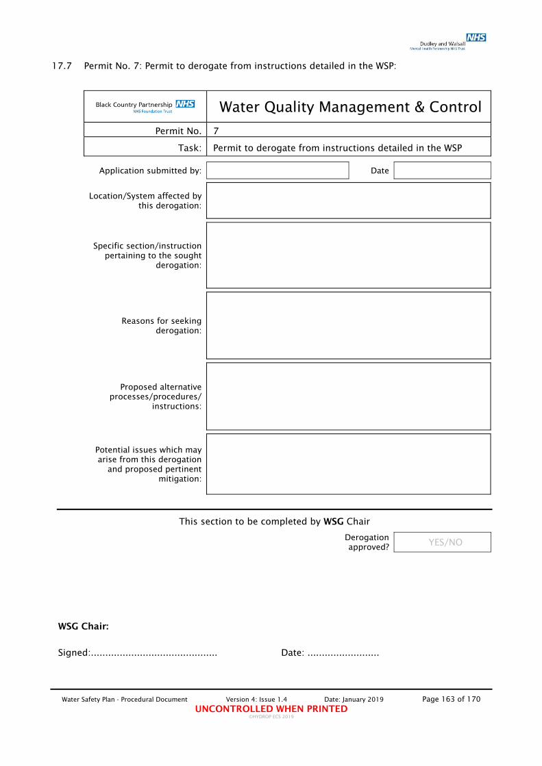
Water Safety Plan - Procedural Document Version 4: Issue 1.4 Date: January 2019 Page 163 of 170 UNCONTROLLED WHEN PRINTED
©HYDROP ECS 2019
17.7 Permit No. 7: Permit to derogate from instructions detailed in the WSP:
Water Quality Management & Control
Permit No. 7
Task: Permit to derogate from instructions detailed in the WSP
Application submitted by: Date
Location/System affected by this derogation:
Specific section/instruction pertaining to the sought
derogation:
Reasons for seeking derogation:
Proposed alternative processes/procedures/
instructions:
Potential issues which may arise from this derogation
and proposed pertinent mitigation:
This section to be completed by WSG Chair
Derogation approved? YES/NO
WSG Chair:
Signed:............................................ Date: .........................

Water Safety Plan - Procedural Document Version 4: Issue 1.4 Date: January 2019 Page 164 of 170 UNCONTROLLED WHEN PRINTED
©HYDROP ECS 2019
17.8 Permit No. 8: Permit to confirm status of implemented Water Quality Management Programme in third-party properties:
Water Quality Management & Control
Permit No. 8
Task: Permit to confirm status of implemented Water Quality Management Programme in third-party properties
All sections in Green to be completed by Responsible Person (Estates) All sections in Red to be completed by Infection Control Lead Nurse All section in Blue to be completed by building owner representative
Building:
Building address:
Building owned by:
Areas occupied by the Trust (indicate % of total
building area):
% of total building
area
Type of usage of areas occupied by the Trust:
Level of risk of
occupants
Period of use of areas occupied by the Trust: Flushing Programme
in place? YES/NO
Common areas of building managed by:
Hard FM: Soft FM
Areas of building occupied by Trust managed by:
Hard FM: Soft FM
Is a suitable and sufficient Risk Assessment (RA) available? Please include report in response
YES/NO Date of RA
Level of Assessed
Risk
Is a Water Safety Plan (WSP) available?
Please include document in response YES/NO Is the WSP adequate and implemented as
detailed? YES/NO
Is a Pre-planned maintenance Programme (PPM) in place?
Please include details in response YES/NO PPM Programme carried
out by:
Is a suitable Log-book system in place?
Please include details in response YES/NO Is the information contained within
shared with the Trust: YES/NO
Additional information
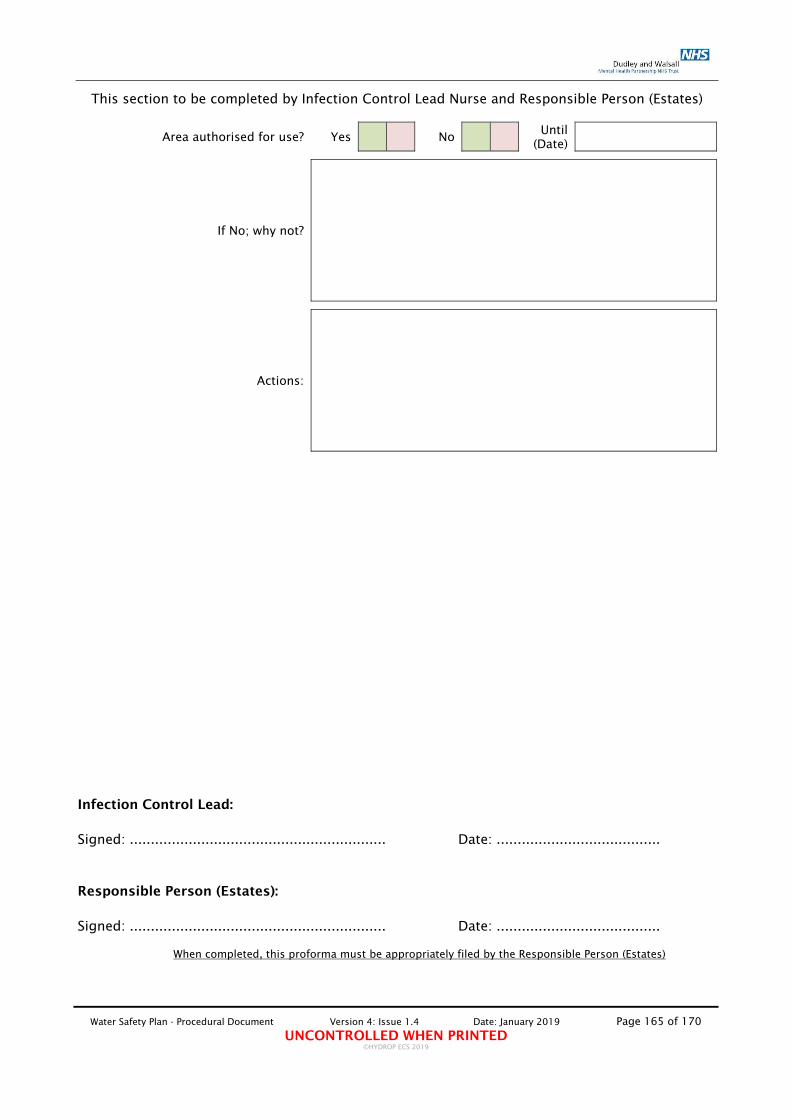
Water Safety Plan - Procedural Document Version 4: Issue 1.4 Date: January 2019 Page 165 of 170 UNCONTROLLED WHEN PRINTED
©HYDROP ECS 2019
This section to be completed by Infection Control Lead Nurse and Responsible Person (Estates)
Area authorised for use? Yes No Until (Date)
If No; why not?
Actions:
Infection Control Lead: Signed: ............................................................. Date: .......................................
Responsible Person (Estates): Signed: ............................................................. Date: .......................................
When completed, this proforma must be appropriately filed by the Responsible Person (Estates)

Water Safety Plan - Procedural Document Version 4: Issue 1.4 Date: January 2019 Page 166 of 170 UNCONTROLLED WHEN PRINTED
©HYDROP ECS 2019
17.9 Permit No. 9: Application and Approval for Installation of Supplementary Control Measure:
Water Quality Management & Control
Permit No. 9
Task: Application and Approval for Installation of Supplementary Control Measure
Application submitted by: Date
Name and address of facility to be treated:
Reasons why supplementary bacterial control is
necessary:
Evidence, data and information used to
construct the rationale:
'Failed' parameters and the reasons why these are
considered to be failing
Details of the proposed supplementary control
measure (type of chemical, expected levels, etc.)
Duration of use of supplementary control
measure:
Interim control measures during the installation of
the supplementary control method and anticipated
elevated risks during installation, short-term, medium-term and long-
term:
Exit strategy and parameters used to
construct this strategy:
Has the installation specification been
prepared? Yes No Estimated costs:
Installation process & mechanical facilitation works required? Please
state:
Tendered of preferred supplier (if preferred supplier
please state):
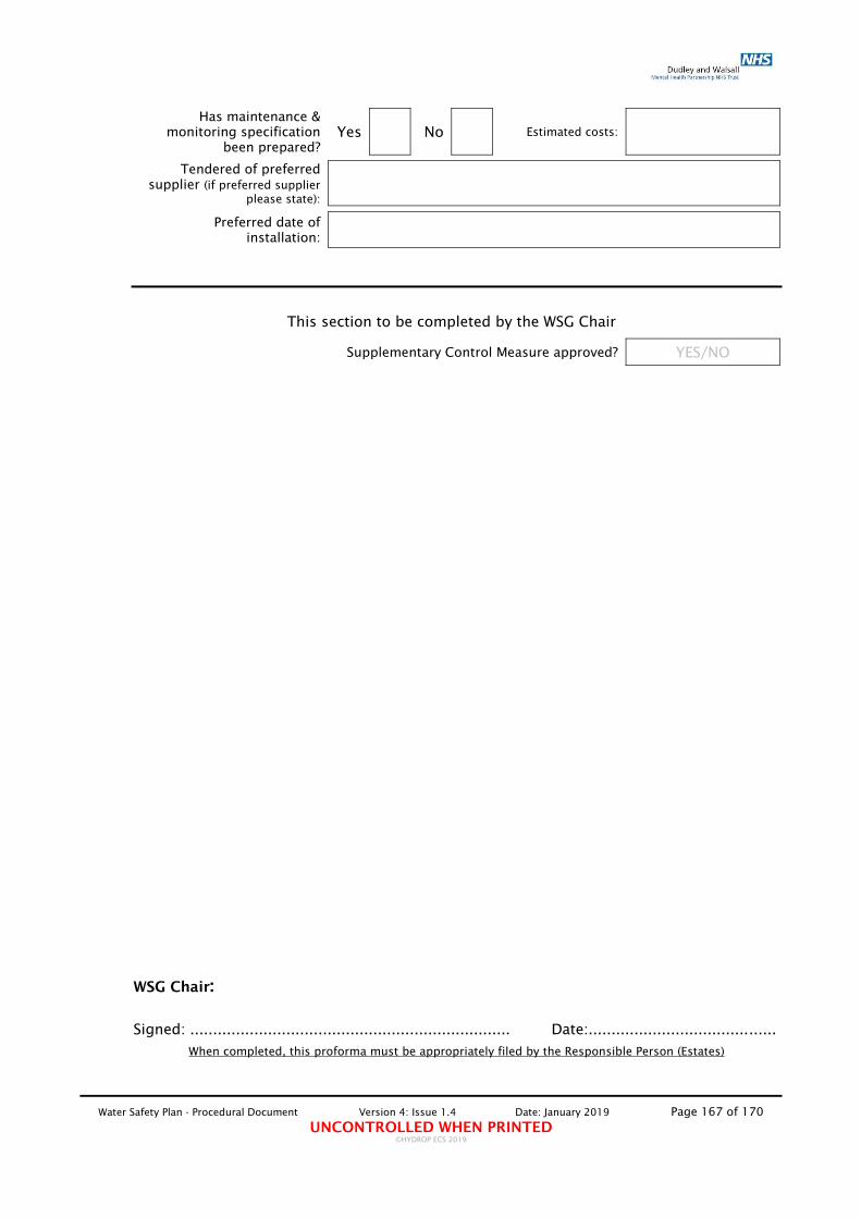
Water Safety Plan - Procedural Document Version 4: Issue 1.4 Date: January 2019 Page 167 of 170 UNCONTROLLED WHEN PRINTED
©HYDROP ECS 2019
Has maintenance &
monitoring specification been prepared?
Yes No Estimated costs:
Tendered of preferred supplier (if preferred supplier
please state):
Preferred date of installation:
This section to be completed by the WSG Chair
Supplementary Control Measure approved? YES/NO
WSG Chair: Signed: ...................................................................... Date:.........................................
When completed, this proforma must be appropriately filed by the Responsible Person (Estates)

Water Safety Plan - Procedural Document Version 4: Issue 1.4 Date: January 2019 Page 168 of 170 UNCONTROLLED WHEN PRINTED
©HYDROP ECS 2019
17.10 Permit No. 10: Permit for the Installation of new Water Dispenser / Water Cooler:
Water Quality Management & Control
Permit No. 10
Task: Permit for the Installation of new Water Dispenser / Water Cooler
Management Criteria
Application submitted by: Date
Proposed location of Water Dispensers/Water Cooler:
Assessed Patient Risk
Level:
Water Dispensers/Water Cooler to be procured by:
Water Dispensers/Water Cooler to be supplied by:
Water Dispensers/Water Cooler make and model;
Proposed date of unit installation:
Water Dispensers/Water Cooler to be installed by:
Is installer approved by
the WSG (Yes/No)
Unit to be maintained by: Contract start/end date:
Is unit included in the PPM Programme? Contract
start/end date:
Please Note: The selection and maintenance of each Water Dispenser/Water Cooler must be in accordance with 'Process No. 18 Management of Water Dispensers/Water Coolers.
Water Dispensers/Water Cooler Features
Is unit selected WRAS approved and suitably approved by all relevant bodies for the use in a healthcare environment?
YES NO N/A
Does unit have a water storage tank? YES NO N/A
Does unit use UV bacterial control? YES NO N/A
Does unit have hot and cold facility? YES NO N/A
Does unit have replacement spout facility? YES NO N/A
Does unit have the capacity to chill water below 10oC? YES NO N/A
State maximum flow-rate of unit? YES NO N/A
Is unit connected to mains using flexible hose made of EPDM rubber? YES NO N/A
Does unit construction incorporate seals/gaskets made from EPDM rubber? YES NO N/A
Water Dispensers/Water Cooler Installation approved by Water Safety Group? YES/NO
Responsible Person (Estates): Signed: .............................................. Date:.....................
NOTE: TO ALLOW FOR THE INSTALLATION OF THE WATER DISPENSERS/WATER COOLER THIS PRO-FORMA MUST BE ACCOMPANIED BY MANUFACTURER'S TECHNICAL DATA
A SIGNED COPY OF THIS PERMIT MUST BE SUPPLIED TO THE PERSON/DEPARTMENT RESPONSIBLE FOR THE MANAGEMENT AND MAINTENANCE OF THE UNIT. THIS PERMIT MUST BE PRODUCED WHEN REQUESTED BY THE RESPONSIBLE PERSON (ESTATES) TO PROVE AUTHORISATION FOR INSTALLATION. FAILURE TO
PROVIDE A SIGNED PERMIT WOULD ALLOW THE RESPONSIBLE PERSON (ESTATES) TO DISCONNECT AND REMOVE THE UNIT
When completed, this proforma must be appropriately filed by the Responsible Person (Estates)

Water Safety Plan - Procedural Document Version 4: Issue 1.4 Date: January 2019 Page 169 of 170 UNCONTROLLED WHEN PRINTED
©HYDROP ECS 2019
18. APPENDIX 7 – CURRENT RISK ASSESSMENT STATUS
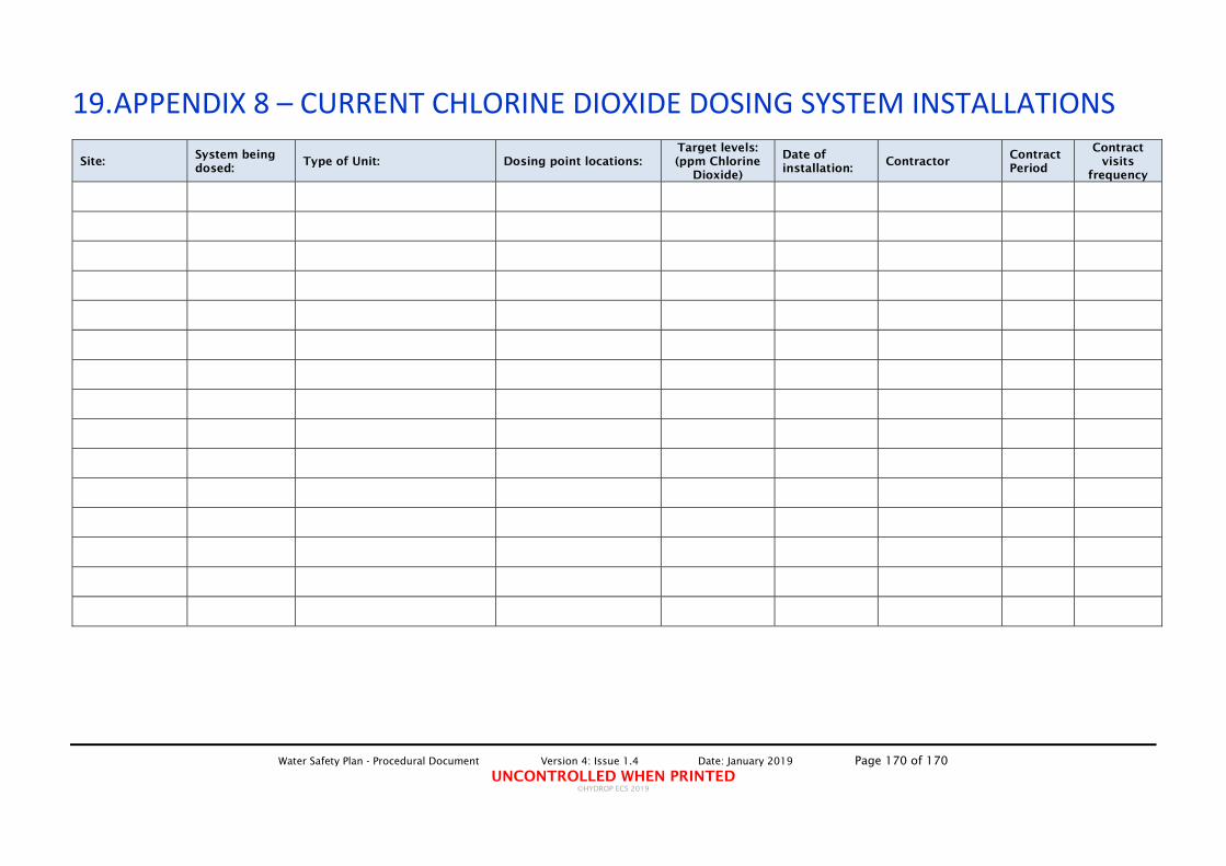
Water Safety Plan - Procedural Document Version 4: Issue 1.4 Date: January 2019 Page 170 of 170 UNCONTROLLED WHEN PRINTED
©HYDROP ECS 2019
19. APPENDIX 8 – CURRENT CHLORINE DIOXIDE DOSING SYSTEM INSTALLATIONS
Site: System being dosed:
Type of Unit: Dosing point locations: Target levels: (ppm Chlorine
Dioxide)
Date of installation:
Contractor Contract Period
Contract visits
frequency