Water Level Measurement and Tidal Datum Transfer … Level Measurement and Tidal Datum ... Water...
15
TS 5I - Hydrographic Surveying in Practice Andrew Marshall and Paul Denys Water Level Measurement and Tidal Datum Transfer Using High Rate GPS Buoys Integrating Generations FIG Working Week 2008 Stockholm, Sweden 14-19 June 2008 1/15 Water Level Measurement and Tidal Datum Transfer Using High Rate GPS Buoys Andrew MARSHALL and Paul DENYS, New Zealand Key words: GPS Buoy, Tidal Datum Transfer, Cadastral Boundaries, MHWS, Sea Level SUMMARY The transfer of tidal datums using high rate GPS buoys offers advantages over traditional techniques, which may be limited by their practicality, efficiency and cost. This paper describes an experiment where two GPS buoys were deployed simultaneously near two tide gauges within Otago Harbour, New Zealand. The tide gauge records were used to verify, first, that GPS buoys can measure water levels, and second, test the accuracy to which a tidal datum can be transferred based on water levels estimated by the buoy. It was found that a datum could be transferred at similar accuracy to previous experiments, concluding that GPS buoys are a viable means of tidal datum transfer. With rising sea levels and an increasing demand for coastal properties, cadastral surveyors and engineers need to be able to readily define cadastral boundaries both reliably and accurately. The use of GPS buoys has the following advantages for tidal datums transfer: Efficient datum connections between the GPS buoy and benchmark. Expedient and relatively easy data collection. Existing GPS equipment can be used. GPS buoys can be deployed in close proximity to the shore and do not have to be attached to an existing tide gauge instrument.
Transcript of Water Level Measurement and Tidal Datum Transfer … Level Measurement and Tidal Datum ... Water...

TS 5I - Hydrographic Surveying in Practice
Andrew Marshall and Paul Denys
Water Level Measurement and Tidal Datum Transfer Using High Rate GPS Buoys
Integrating Generations
FIG Working Week 2008
Stockholm, Sweden 14-19 June 2008
1/15
Water Level Measurement and Tidal Datum Transfer
Using High Rate GPS Buoys
Andrew MARSHALL and Paul DENYS, New Zealand
Key words: GPS Buoy, Tidal Datum Transfer, Cadastral Boundaries, MHWS, Sea Level
SUMMARY
The transfer of tidal datums using high rate GPS buoys offers advantages over traditional
techniques, which may be limited by their practicality, efficiency and cost. This paper
describes an experiment where two GPS buoys were deployed simultaneously near two tide
gauges within Otago Harbour, New Zealand. The tide gauge records were used to verify,
first, that GPS buoys can measure water levels, and second, test the accuracy to which a tidal
datum can be transferred based on water levels estimated by the buoy. It was found that a
datum could be transferred at similar accuracy to previous experiments, concluding that GPS
buoys are a viable means of tidal datum transfer.
With rising sea levels and an increasing demand for coastal properties, cadastral surveyors
and engineers need to be able to readily define cadastral boundaries both reliably and
accurately. The use of GPS buoys has the following advantages for tidal datums transfer:
� Efficient datum connections between the GPS buoy and benchmark. � Expedient and relatively easy data collection. � Existing GPS equipment can be used. � GPS buoys can be deployed in close proximity to the shore and do not have to be
attached to an existing tide gauge instrument.
TS 5I - Hydrographic Surveying in Practice
Andrew Marshall and Paul Denys
Water Level Measurement and Tidal Datum Transfer Using High Rate GPS Buoys
Integrating Generations
FIG Working Week 2008
Stockholm, Sweden 14-19 June 2008
2/15
Water Level Measurement and Tidal Datum Transfer
Using High Rate GPS Buoys
Andrew MARSHALL and Paul DENYS, New Zealand
1. INTRODUCTION
Tidal datums are used for a number of important purposes. They provide reference surfaces
for navigational charts (e.g. chart datum, Chang and Sun (2004)); height datums (e.g. mean
sea level, Hannah (1989)); as an indicator of climate change (Pugh, 2004) and as the basis for
defining various coastal cadastral jurisdictional boundaries (Baker and Watkins, 1991). For
some applications, a tidal datum must be transferred between locations and tide gauges have
typically been used in the past. However, with GPS buoy technology being capable of
estimating heights at the low centimetre level, it could provide a viable alternative method. A
GPS buoy is essentially a GPS antenna mounted on a floating platform.
Traditional methods and techniques have limitations in practicality, efficiency, cost and
accuracy (Goring, 2007). Dewar and Hannah (2005) discussed two general methods for
transferring tidal datums using levelling (either spirit or GPS levelling) and tidal datum
transfer techniques. Firstly, levelling can be undertaken using an established gauge as a
starting point. Unfortunately today, terrestrial (or spirit) levelling is time consuming,
expensive and typically requires extensive logistics, such as traffic management planning.
Alternatively, GPS levelling, which measures ellipsoidal height differences, can overcome
many of the problems associated with terrestrial levelling, but does require a high quality
geoidal undulation model. Both levelling techniques ignore local sea surface effects.
Secondly, tidal datum transfer methods can be used, where a temporary tide gauge is set up at
a remote site and the datum transferred by comparing tidal observations at both the temporary
and a nearby permanent gauge. Traditionally in cadastral surveying, a simple tide staff is
used at the remote site, which can be inefficient and has a low level of accuracy due to the
manual observations required. More generally, tide gauges may be difficult to install at many
locations where it is difficult to rigidly fix them.
Using a GPS buoy to measure water levels offers many advantages over traditional techniques
with its ability to determine heights relative to an absolute reference frame. While large scale
GPS buoys have been used for long-term datum determination (e.g. Arroyo-Saurez et al.,
2005), there has been little research involving light-weight designs for short-term tidal datum
transfers. However, Abidin (1999) did suggest that small systems using GPS did show
potential for this type of application. The purpose of this study was to determine the viability
of GPS buoy technology in transferring tidal datums. In particular, the ability of a high rate
GPS buoy to measure the sea level was verified by determining its precision and accuracy
relative to tide gauge observations. Furthermore, it aimed to demonstrate how accurately a
tidal datum could be transferred using the sea levels estimated by the GPS buoy.

TS 5I - Hydrographic Surveying in Practice
Andrew Marshall and Paul Denys
Water Level Measurement and Tidal Datum Transfer Using High Rate GPS Buoys
Integrating Generations
FIG Working Week 2008
Stockholm, Sweden 14-19 June 2008
3/15
The experiment was undertaken in Otago Harbour - a 22 km long tidal inlet that is located on
the eastern coast of the South Island of New Zealand. Existing tide gauges, located
approximately 10 km apart, were used to provide a means of calibration and comparison.
These were situated at two port facilities, Port Chalmers and the Dunedin Wharf (Figure 1).
Figure 1: The Otago Harbour tide gauge deployment locations
2. WATER LEVEL MEASUREMENT USING GPS BUOYS
�������������� ��� ��� ���� ����������� ��� �������et al. (1994)) GPS buoy technology has
rapidly progressed in both design and applications. This has been largely driven by their use
for absolute calibration of satellite altimeters (Schone, 2001), with applications ranging from
tsunami monitoring (Kato et al., 2001) to river level monitoring (Moore et al., 2000).
Research has typically involved three types of design:
1. Lightweight wave rider, which must be tethered and operated from a boat
2. Autonomous lightweight wave rider, housing all the necessary equipment within the
buoy
3. Autonomous, large scale buoy for use in long-term rugged environments
The advantages, disadvantages and applications of these designs are summarised in Table 1.

TS
5I
- H
yd
rogra
phic
Su
rveyin
g i
n P
ract
ice
And
rew
Mar
shall
an
d P
aul
Den
ys
Wate
r L
evel
Mea
sure
men
t an
d T
idal
Dat
um
Tra
nsf
er
Usi
ng
Hig
h R
ate
GP
S B
uo
ys
Inte
gra
tin
g G
ener
atio
ns
FIG
Wo
rkin
g W
eek
20
08
Sto
ck
ho
lm,
Sw
eden 1
4-1
9 J
un
e 2
00
8
4/1
5
GP
S B
uoy
Des
ign
D
escr
ipti
on
A
dv
an
tag
es
Dis
ad
va
nta
ges
A
pp
licati
on
Ex
am
ple
s
Lig
htw
eig
ht
wa
ve
rid
er
(an
ten
na o
nly
)
e.g
. (K
ey
et
al.,
19
98
),
(Ch
eng,
20
05
)
� A
li
gh
t-w
eig
ht
buo
y
usu
all
y
usi
ng
a
life
p
rese
rver
as
the
flo
ata
tio
n s
ou
rce �
Th
e b
uo
y c
an b
e o
per
ated
fro
m
a b
oat
an
d
on
ly
ho
use
s th
e G
PS
ante
nn
a �
Th
e
an
ten
na
off
set
fro
m
the
mea
n w
ater
lev
el
is s
mall
, ty
pic
all
y
po
siti
on
ed 5
0�2
50
mm
ab
ov
e it
� E
co
no
mic
al
and
si
mp
le
to
co
nst
ruct
, w
ith
lo
w co
st
mat
eria
ls
that
are
read
ily a
vail
able
� E
asi
ly p
ort
able
wit
h t
heir
sm
all
size � N
o n
eed t
o m
on
ito
r an
d c
orr
ect
����������� ����� �
Lo
w c
en
tre o
f m
ass
� L
og
isti
cal
sup
po
rt
is
requ
ired
thro
ug
hou
t th
e
enti
re
dep
loym
en
t
(pers
on
al a
nd
bo
ats
) � L
ack
of
vers
ati
lity
w
ith
th
e
teth
er
req
uir
ed �
Dep
loym
ent
rest
rict
ed i
n r
ou
gh
sea
con
dit
ion
s � S
ho
rt
du
rati
on
d
eplo
ym
en
ts
on
ly (
Wats
on
, 2
00
5)
� A
bso
lute
alt
imete
r ca
lib
rati
on
� T
idal
Datu
m T
ran
sfer �
Ort
ho
metr
ic
hei
gh
t tr
ansf
er
over
wat
er
(measu
rin
g
geo
idal
slo
pe)
� R
iver
an
d
lak
e
level
mo
nit
ori
ng �
Hig
h f
req
uen
cy w
av
e an
aly
sis �
Map
pin
g t
he s
ea s
urf
ace
Au
ton
om
ou
s
lig
htw
eig
ht
wa
ve r
ider
e.g
. (P
ark
er, 2
00
7)
� A
li
gh
t-w
eig
ht
bu
oy as
abo
ve,
exce
pt
it h
ou
ses
the
GP
S re
cei
ver,
ante
nn
a a
nd
bat
tery
� C
an
op
era
te
auto
no
mo
usl
y,
eith
er:
an
cho
red
, d
rift
ing
or
teth
ered
� A
s ab
ove �
Red
uce
d
logis
tics
co
nsi
dera
tion
s,
wit
h
au
ton
om
ou
s
op
era
tio
n o
f up
to
5 d
ays
� A
s ab
ove �
Red
uced
lo
gis
tics
con
sid
era
tion
s � D
eplo
ym
ent
tim
e is
sti
ll l
imit
ed
to s
ho
rt t
o m
ediu
m t
erm
s
� A
s ab
ove �
Veri
fyin
g a
nd
cali
bra
tin
g t
ide
gau
ges �
Ap
pli
cat
ion
s re
qu
irin
g
auto
no
mo
us
(sta
nd
alo
ne)
op
erat
ion
fo
r p
eri
od
s <
1w
eek
Au
ton
om
ou
s, l
arg
e sc
ale
e.g
.(K
ato
et
al.,
2
00
1),
(A
rro
yo
-
Sau
rez
et a
l.,
20
05
)
� A
la
rge,
rug
ged
b
uo
y
that
ho
use
s th
e G
PS
syst
em
in
ad
dit
ion
to p
ow
er s
tora
ge
an
d g
enera
tio
n a
nd
dat
a c
om
mu
nic
atio
ns �
Can
o
per
ate
auto
no
mo
usl
y
for
sign
ific
ant
du
rati
on
s � T
he an
ten
na re
fere
nce
p
oin
t is
typ
icall
y
5-7
m
ab
ov
e th
e
mea
n
wate
r le
vel
(W
ats
on
, 20
05
)
� C
an
op
erat
e
for
lon
g
tim
e
peri
od
s and
in
ro
ug
h s
ea
con
dit
ion
s
� A
dd
itio
nal
se
nso
rs
can
be
inte
gra
ted
in
to
the
bu
oy,
such
as
mete
oro
logic
al
inst
rum
en
ts
(Wat
son
. 2
00
5)
� H
igh
Co
st �
No
t ea
sily
po
rtab
le �
Can
be d
iffi
cu
lt t
o m
eas
ure
an
d
��������������� �����������������
������������ ��� ���������������
wate
r le
vel
. � R
elia
bil
ity
issu
es
wit
h
po
wer
and
co
mm
unic
atio
ns
(Wats
on,
200
5)
� T
sun
am
i m
on
ito
ring
� T
idal
Datu
m D
ete
rmin
ati
on
� A
bso
lute
alt
imete
r ca
lib
rati
on
� L
on
g t
erm
tid
al
mo
nit
ori
ng
Ta
ble
1:
Ad
van
tag
es, d
isad
van
tages
an
d a
ppli
cati
ons
of
the
thre
e m
ajor
GP
S b
uoy d
esig
ns.
T
able
layo
ut
fro
m W
ats
on
(20
05
)

TS 5I - Hydrographic Surveying in Practice
Andrew Marshall and Paul Denys
Water Level Measurement and Tidal Datum Transfer Using High Rate GPS Buoys
Integrating Generations
FIG Working Week 2008
Stockholm, Sweden 14-19 June 2008
5/15
3. METHODOLGY
3.1 GPS Buoy Design
The GPS buoy used in this study is of the wave rider style that was designed to operate
autonomously. It consisted of a simple square block of polystyrene with the GPS box
inserted into its centre. This box contained the GPS receiver (Trimble 5700) and battery,
with the antenna (Trimble Zephyr Geodetic) fixed on top (Figure 2). Both the tether and shape
of the buoy were key design considerations as t������������������������ ����������������
dynamics and therefore the mean vertical position above the water surface. In order to
����������� �������������������������������������������������������������������
buoy was connected to a secondary float before being attached to either an anchor or pile.
Figure 2: Sectional view of the GPS Buoy
3.2 Antenna Height Offset
Determining the height of the antenna above the mean water surface is a fundamental part of
measuring absolute sea surface heights. In this experiment a spirit level and lightweight
measuring rod were used to measure the height difference between the centre point on the top
of the antenna and a bench mark that the water level had been raised to. This was carried out
in a controlled environment using a temporary tank filled with fresh water with the buoy in its
full deployment state. A correction for ocean salinity was made to the height difference
between the antenna reference point (ARP) and mean water surface. The antenna offsets for
the buoys were ~ 0.264 m ± 0.002m.
3.3 Deployment
Two GPS buoys were deployed simultaneously at Port Chalmers and Dunedin Wharf (Figure
1) within close proximity to existing tide gauges. Observations were made at a 5-second rate
over a period of four days. Higher rates, such as 1 Hz are frequently used for GPS buoy data
collection (Watson, 2005), however the difference in the precision and mean of the height
difference between the tide gauge and GPS buoy was less than 1 mm when the higher rate
was used. Because of the difficulties in processing and managing the increased data, 5-
12V Battery
GPS
Receiver
Zephyr Geodetic antenna
Square polystyrene float
Black polythene wrapping
Sealed bung enabling antenna cable outlet
Approx. water level
0.8m
Draft = ~27mm

TS 5I - Hydrographic Surveying in Practice
Andrew Marshall and Paul Denys
Water Level Measurement and Tidal Datum Transfer Using High Rate GPS Buoys
Integrating Generations
FIG Working Week 2008
Stockholm, Sweden 14-19 June 2008
6/15
second epoch observations were made. A minimum of 3 days is required for successful use
of the range ratio method of tidal datum transfer (Grant and O'Reilly, 1986), with four days of
tidal observa���������������� ����������������� ����������������������������������������
tide gauges. These observations were post-processed using GPS reference stations co-located
with the gauges. Outliers were a common feature of the processed GPS heights and were
identified by the clear jumps in the heights compared to the tidal pattern. These were
possibly caused by the carrier phase ambiguities being incorrectly resolved and were
removed. Figure 3 shows the GPS buoy being deployed at Port Chalmers.
Figure 3: GPS Buoy deployment at the Port Chalmers tide gauge site
To directly compare the sea level observations from the tide gauge (relative to chart datum)
and the GPS buoy (relative to the GRS80 ellipsoid), the observed heights are required to be
reduced to the same reference surface. (Figure 4). In this situation the height difference
between the ellipsoid and orthometric height datum at the reference station, (hREF - HREF),
was used in combination with the geoidal undulation between this position and that of the
buoy, (�
NREF � Buoy), to determine ellipsoidal-orthometric separation at the buoy (~NBuoy). The
calculated offset to chart datum, (CDOffset), was then applied to reduce the GPS buoy heights
to chart datum (GPSBuoySSH).
The buoy should preferably be positioned within 200 m of the tide gauge being used for
verification and the reference station (Watson, 2005). This both simplifies the GPS
processing, as some errors in the GPS observables will be correlated between the two sites, as
well as minimising the effects of geoidal undulation and dynamic sea surface topography
(Figure 4). Sea surface topography is the difference in the mean sea surface due to the effects
of wind, temperature, salinity and current between two locations. For most tidal datum
transfer situations, there is often no orthometric height control close to the subordinate station
and therefore the tidal observations and datum transfer must be made relative to another
datum. A tide gauge is often referenced arbitrarily to a nearby benchmark so that when GPS
buoys are used to transfer a datum, the reference height can be relative to the ellipsoid at the
GPS base station benchmark or alternatively a geoid-ellipsoid separation model can be used
to reduce the ellipsoidal height to an orthometric height surface.

TS 5I - Hydrographic Surveying in Practice
Andrew Marshall and Paul Denys
Water Level Measurement and Tidal Datum Transfer Using High Rate GPS Buoys
Integrating Generations
FIG Working Week 2008
Stockholm, Sweden 14-19 June 2008
7/15
Figure 4: Datum connections and methodology for verification of the GPS buoy with the tide gauge
3.4 Verification
������������������ ������������������������������������������ �� ��� filtered GPS heights
were directly compared to those from the existing tide gauge at the location. The difference
( GPSBuoyTGDifference � ) between the tide gauge and GPS buoy measured heights was computed
as.
HFilteredSSSSHGPSBuoyTG GPSBuoyTGDifference ���
where SSHTG is the tide gauge sea surface heights (relative to chart datum) and
HFilteredSSGPSBuoy is the GPS buoy filtered sea surface heights. The GPS buoy heights
������������������������������������� ������������� ����������������������������d different
observation sampling rates, with the tide gauge taking the mean of every 30 seconds prior to
the tenth minute. Upon analysis a 3 minute sampling period was selected and any outliers
removed. This enabled both the precision as well as absolute and systematic biases between
the two systems to be determined from these differences.
TS 5I - Hydrographic Surveying in Practice
Andrew Marshall and Paul Denys
Water Level Measurement and Tidal Datum Transfer Using High Rate GPS Buoys
Integrating Generations
FIG Working Week 2008
Stockholm, Sweden 14-19 June 2008
8/15
3.5 Tidal Datum Transfer
The range ratio method was used to transfer the tidal datum MHWS between Port Chalmers
and Dunedin Wharf and vice versa. Three days of simultaneous GPS buoy observations were
used. The high and low points required for this technique were determined by fitting
polynomial curves to the extremities of the data (typically over a two hour period). The
range ratio method assumes that the ratio of the vertical distances from the respective datum
planes to mean high water springs (MHWS) at the reference and subordinate sites (i.e.
MHWS/mhws) is equal to the ratio of the observed mean tidal range at the same two sites
(i.e. MR/mr). Thus, the ratio is given as:
mr
MR
mhws
MHWSRatio �:
Marshall (2007) gives the full details of the tidal datum transfer procedures used. This
method was chosen because of both its proven accuracy but also to enable a direct
comparison to previous research undertaken by Dewar and Hannah (2005). However, other
methods may be better suited to other sites depending on their physical and tidal
characteristics. For example, in some locations only part of the tidal range can be observed
because of the influence of mud flats. In this case the modified height difference method
(Dewar and Hannah, 2005) could be used. The least squares method (Grant and O'Reilly,
1986) may be particularly suited to the high rate GPS buoy data, however this requires further
investigation.
4. RESULTS AND ANALYSIS
4.1 GPS Buoy Verification
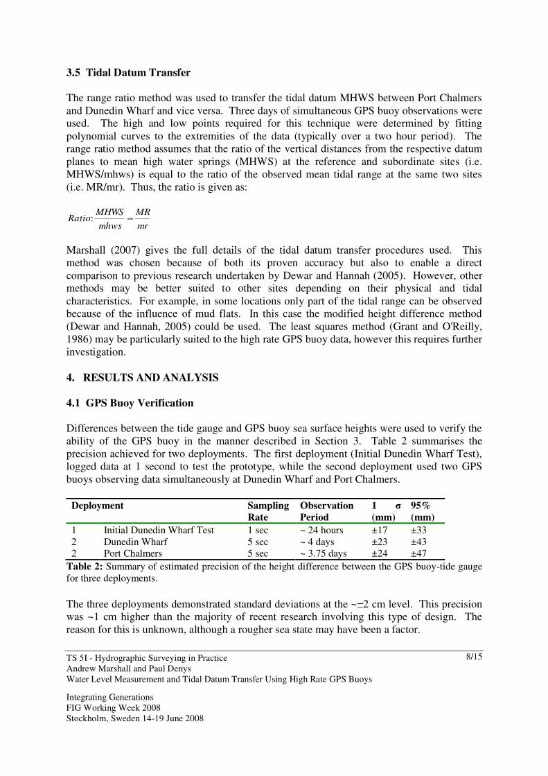
Differences between the tide gauge and GPS buoy sea surface heights were used to verify the
ability of the GPS buoy in the manner described in Section 3. Table 2 summarises the
precision achieved for two deployments. The first deployment (Initial Dunedin Wharf Test),
logged data at 1 second to test the prototype, while the second deployment used two GPS
buoys observing data simultaneously at Dunedin Wharf and Port Chalmers.
Deployment Sampling
Rate
Observation
Period
1 ��
(mm)
95%
(mm)
1 Initial Dunedin Wharf Test 1 sec ~ 24 hours ±17 ±33
2 Dunedin Wharf 5 sec ~ 4 days ±23 ±43 2 Port Chalmers 5 sec ~ 3.75 days ±24 ±47
Table 2: Summary of estimated precision of the height difference between the GPS buoy-tide gauge
for three deployments.
The three deployments demonstrated standard deviations at the ~ 2 cm level. This precision
was ~1 cm higher than the majority of recent research involving this type of design. The
reason for this is unknown, although a rougher sea state may have been a factor.

TS 5I - Hydrographic Surveying in Practice
Andrew Marshall and Paul Denys
Water Level Measurement and Tidal Datum Transfer Using High Rate GPS Buoys
Integrating Generations
FIG Working Week 2008
Stockholm, Sweden 14-19 June 2008
9/15
Figure 5 is an example of the unfiltered sea surface heights graph of the tide variation over
the four days while Figure 6 graphs the difference between the tide gauge height and GPS
buoy (filtered) height.
(Outliers Removed)
4.40
4.60
4.80
5.00
5.20
5.40
5.60
5.80
6.00
6.20
6.40
25/05/2007 12:00 26/05/2007 0:00 26/05/2007 12:00 27/05/2007 0:00 27/05/2007 12:00 28/05/2007 0:00 28/05/2007 12:00 29/05/2007 0:00 29/05/2007 12:00
Date/Time (NZST)
Ge
od
eti
c H
eig
ht
(m)
Day1 Day2 Day3 Day4
Figure 5: Dunedin Wharf deployment sea surface height estimates from the unfiltered GPS buoy data
-0.08
-0.06
-0.04
-0.02
0.00
0.02
0.04
0.06
0.08
25/05/2007 12:00 26/05/2007 0:00 26/05/2007 12:00 27/05/2007 0:00 27/05/2007 12:00 28/05/2007 0:00 28/05/2007 12:00 29/05/2007 0:00 29/05/2007 12:00
Date/Time (NZST)
He
igh
t D
iffe
ren
ce
(m
)
y = -0.00002x + 0.008
Figure 6: Dunedin Wharf deployment residual difference between the filtered GPS buoy data and the
tide gauge
Deployment:
Initial
Dunedin
Wharf
Test
Dunedin
Wharf
Port
Chalmers
Chart datum to ellipsoid offsets
Measured
Datum Offsets
(m)
4.322 4.322 4.450
Mean
GPSBuoyTGDifference (m)
4.309 4.319 4.443
Absolute bias between TG and
filtered GPS buoy SSH (reduced to
CD)
Mean
GPSBuoyTGDifference (m)
+0.013 +0.003 +0.007
Table 3: Comparison of geodetic to chart datum offsets
TS 5I - Hydrographic Surveying in Practice
Andrew Marshall and Paul Denys
Water Level Measurement and Tidal Datum Transfer Using High Rate GPS Buoys
Integrating Generations
FIG Working Week 2008
Stockholm, Sweden 14-19 June 2008
10/15
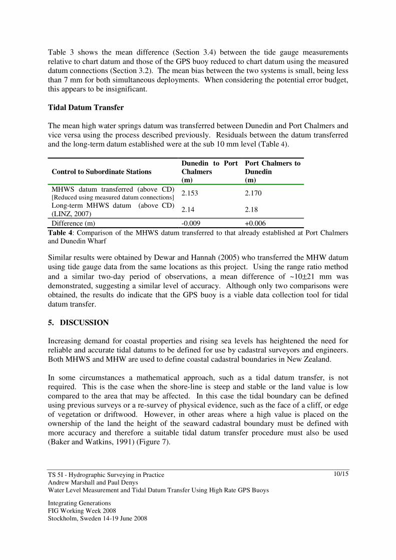
Table 3 shows the mean difference (Section 3.4) between the tide gauge measurements
relative to chart datum and those of the GPS buoy reduced to chart datum using the measured
datum connections (Section 3.2). The mean bias between the two systems is small, being less
than 7 mm for both simultaneous deployments. When considering the potential error budget,
this appears to be insignificant.
Tidal Datum Transfer
The mean high water springs datum was transferred between Dunedin and Port Chalmers and
vice versa using the process described previously. Residuals between the datum transferred
and the long-term datum established were at the sub 10 mm level (Table 4).
Control to Subordinate Stations
Dunedin to Port
Chalmers
(m)
Port Chalmers to
Dunedin
(m)
MHWS datum transferred (above CD) [Reduced using measured datum connections]
2.153 2.170
Long-term MHWS datum (above CD)
(LINZ, 2007) 2.14 2.18
Difference (m) -0.009 +0.006
Table 4: Comparison of the MHWS datum transferred to that already established at Port Chalmers and Dunedin Wharf
Similar results were obtained by Dewar and Hannah (2005) who transferred the MHW datum
using tide gauge data from the same locations as this project. Using the range ratio method
and a similar two-day period of observations, a mean difference of ~10 21 mm was
demonstrated, suggesting a similar level of accuracy. Although only two comparisons were
obtained, the results do indicate that the GPS buoy is a viable data collection tool for tidal
datum transfer.
5. DISCUSSION
Increasing demand for coastal properties and rising sea levels has heightened the need for
reliable and accurate tidal datums to be defined for use by cadastral surveyors and engineers.
Both MHWS and MHW are used to define coastal cadastral boundaries in New Zealand.
In some circumstances a mathematical approach, such as a tidal datum transfer, is not
required. This is the case when the shore-line is steep and stable or the land value is low
compared to the area that may be affected. In this case the tidal boundary can be defined
using previous surveys or a re-survey of physical evidence, such as the face of a cliff, or edge
of vegetation or driftwood. However, in other areas where a high value is placed on the
ownership of the land the height of the seaward cadastral boundary must be defined with
more accuracy and therefore a suitable tidal datum transfer procedure must also be used
(Baker and Watkins, 1991) (Figure 7).

TS 5I - Hydrographic Surveying in Practice
Andrew Marshall and Paul Denys
Water Level Measurement and Tidal Datum Transfer Using High Rate GPS Buoys
Integrating Generations
FIG Working Week 2008
Stockholm, Sweden 14-19 June 2008
11/15
Typically a tide pole has been used by surveyors as part of the process to determine this
coastal boundary at the subordinate site, with these observations then combined with those
sourced from the permanent (control) tide gauge. However, the use of GPS buoys may have
advantages in many situations. A particular environment where it may be particularly useful
is in estuarine areas involving high value land, where there is little wave action and a flat
gradient (Figure 7). The vertical error therefore has a large effect on the horizontal position
of the boundary because of the slope. It should be noted that for best results a GPS buoy
would need to be deployed at both locations to ensure the lower frequency observations from
the control tide gauge does not degrade the quality of the transferred datum. However,
typically a cadastral surveyor is expected to use a sole buoy at the subordinate station.
Figure 7: Photo of a coastline showing coastal cadastral boundary determination datums and
concepts
The perceived advantages of the GPS buoy are: � Efficient datum connections between the GPS buoy and benchmark eliminates the
need for levelling to the tide gauge/staff and errors associated with this. This is probably one
of the biggest advantages of high rate GPS buoys. � Efficiency and time saved in data collection, with no manual observations required.
This saves time, money and inconvenience. � Existing GPS equipment as owned by a typical surveying firm can be used in
combination with cheap readily available materials for buoy construction. � Potential for increased accuracy in the datum transferred because of higher frequency
observations. This is maximised by deploying a GPS buoy at both control and subordinate
locations. � They can also be deployed in close proximity to the shore, while not being required to
be rigidly fixed as with traditional tide gauge instruments (Watson et al., 2007)
GPS buoys should also prove useful for hydrographic survey applications in areas where the
installation of a tide gauge is difficult, such as establishing chart datum to be used as a
reference point for the survey.
TS 5I - Hydrographic Surveying in Practice
Andrew Marshall and Paul Denys
Water Level Measurement and Tidal Datum Transfer Using High Rate GPS Buoys
Integrating Generations
FIG Working Week 2008
Stockholm, Sweden 14-19 June 2008
12/15
6. CONCLUSION
GPS buoy technology was successfully verified and applied to transferring a tidal datum
within Otago Harbour. Increasing coastal development and sea level rise has highlighted the
need for accurate tidal datums; however, existing methods of tidal datum transfer often have
limitations. Although GPS buoy technology has been increasingly applied to many situations
there has been little research investigating the use of light-weight designs for transferring
tidal datums.
GPS buoys were deployed simultaneously at Port Chalmers and Dunedin Wharf tide gauges
for four days allowing its observations to be compared against those of the gauges. These
differences were less precise than expected, with a standard deviation at the 2 cm level but
with no significant bias between the two systems. The tidal datum MHWS was transferred
and compared to that established from long-term tidal observations, with residuals at the 10
mm level.
It can be concluded that GPS buoys are a viable means of transferring tidal datums. The
buoys were demonstrated to be simple and cheap to construct, while also being able to utilise
typical GPS surveying equipment. It is therefore considered to have real potential for use in
tidal data collection in many situations.
REFERENCES
Abidin, H. Z. (1999) Monitoring Sea Level Using GPS. In: Proceeding International Seminar
on Application of Seawatch Indonesia Information System for Indonesian Marine Resources
Development. Jakarta, March 10-11 1999. Available at:
http://seawatch.50megs.com/gambar/10.pdf [Accessed: 14 April 2007]
Arroyo-Saurez, E. N., Mabey, D. L., Hsiao, V. and Phillips, R. (2005) Implementation of a
Positioning and Telemetry Buoy to Determine Chart Datum for Hydrographic Survey
Applications. In: ION GNSS 18th International Technical Meeting of the Satellite Division.
Long Beach, CA, USA, 13-16 September 2005. Available at: http://op.gfz-
potsdam.de/altimetry/SSG_buoys/ [Accessed: 20 August 2007]
Baker, R. F. and Watkins, M. (1991) Guidance Notes for the Determination of Mean High
Water Mark for Land Title Surveys. New Zealand Institute of Surveyors, Wellington.
Available at: www.surveyors.org.nz [Accessed: 05 March 2007]
Chang, C.-C. and Sun, Y.-D. (2004) Application of a GPS-Based Method to Tidal Datum
Transfer. The Hydrographic Journal, (No.112), 15-20.
Cheng, K.-C. (2005) Analysis of Water Level Measurement Using GPS. Report No. 476.
Geodetic Science and Surveying, Department of Geological Sciences, The Ohio State
University, Columbus, Ohio, USA.
Dewar, P. and Hannah, J. (2005) An Assessment of the Accuracy of Three Tidal Datum
Transfer Procedures in a Harbour Environment. The Hydrographic Journal, (No.117), 3-7.
TS 5I - Hydrographic Surveying in Practice
Andrew Marshall and Paul Denys
Water Level Measurement and Tidal Datum Transfer Using High Rate GPS Buoys
Integrating Generations
FIG Working Week 2008
Stockholm, Sweden 14-19 June 2008
13/15
Goring, D. (2007) Transferring a Survey Datum Across Water. Mulgor Consulting Ltd.,
Christchurch. Available at: http://www.tideman.co.nz/SurveyDatums/SurveyDatums.html
[Accessed: 29 March 2007]
Grant, S. T. and O'Reilly, C. T. (1986) A New Look at Tidal Datum Transfer Procedures. In:
Proceedings FIG XVIII International Congress of Surveyors. Toronto, International
Federation of Surveyors, pp.258-282.
Hannah, J. (1989) Long Term Sea Level Change and its Implications for Geodetic Networks.
Marine Geodesy, 13(2), 91-100.
Kato, T., Terada, Y., Kinoshita, M., Kakimoto, H., Isshiki, H., Moriguchi, T., Takda, M.,
Tanno, T., Kanzaki, M. and Johnson, J. (2001) A New Tsunami Monitoring System Using
RTK-GPS. In: U.S. National Tsunami Hazard Mitigation Program Review and International
Tsunami Symposium. Seattle, Washington, USA, 7-10 August 2001. Available at:
http://www.oso.chalmers.se/~hgs/ESST/Project_TSUNAMI/gps-japan-tsunami.pdf
[Accessed: 10 August 2007]
Kelecy, T. M., Born, G. H., Parke, M. E. and Rocken, C. (1994) Precise Mean Sea level
Measurements Using the Global Positioning System. Journal of Geophysical Research,
99(C4), 7951-7960.
Key, K. W., Parke, M. E. and Born, G. H. (1998) Mapping the Sea Surface Using a GPS
Buoy. Marine Geodesy, 21(1), 67-79.
LINZ (2007) Tidal Level Information for Surveyors. [Online]. Available at:
http://www.linz.govt.nz/core/surveysystem/geodeticinfo/geodeticdatums/tidalinfo [Accessed:
18 June 2007]
Marshall, A. (2007) Water Level Measurement and Tidal Datum Transfer using High Rate
GPS Buoys. BSurv Dissertation, School of Surveying, Otago University, Dunedin.
Moore, T., Close, G. and Moore, R. (2000) RiGHt: River Level Monitoring Using GPS
Heighting. In: ION GPS 2000. Salt Lake City, Utah, USA, September 19-22. Institute of
Navigation. Available at: http://www.gfz-potsdam.de/pb1/op/altimetry/SSG_buoys/
[Accessed: 14 August 2007]
Parker, H. (2007) Accuracy Analysis of Height Transfer and Calibration Verification of
Bottom Mounted Tide Gauges using GPS Buoys. Dissertation, School of Surveying,
University of Otago, Dunedin.
Pugh, D. T. (2004) Changing Sea levels : Effects of Tides, Weather, and Climate. Cambridge,
Cambridge University Press.
Schone, T. (2001) Final Report SSG 2.194 GPS Water Level Measurements. Special Study
Group 2.194: GPS Water Level Measurements, International Association of Geodesy (IAG).
Available at: http://op.gfz-potsdam.de/altimetry/SSG_buoys/ [Accessed: 14 August 2007]
Watson, C., Coleman, R. and Handsworth, R. (2007) Coastal Tide Gauge Calibration: A
Case Study at Macquarie Island Using GPS Buoy Techniques. School of Geography and
Environmental Studies, University of Tasmania. In Press.
Watson, C. S. (2005) Satellite Altimeter Calibration and Validation Using GPS Buoy
Technology. Thesis for Doctor of Philosophy, University of Tasmania, Hobart, Tasmania,
264pp. Available at: http://adt.lib.utas.edu.au/public/adt-TU20060110.152656/ [Accessed:
10/06/2007]

TS 5I - Hydrographic Surveying in Practice
Andrew Marshall and Paul Denys
Water Level Measurement and Tidal Datum Transfer Using High Rate GPS Buoys
Integrating Generations
FIG Working Week 2008
Stockholm, Sweden 14-19 June 2008
14/15
ACKNOWLEDGEMENTS
This research was gratefully supported by a specialist processing unit research bursary from
����� ���������� ��� ��������� � ����������� ���� �������� ��� ���� ������� ��� �����������
technical officers, Alastair Neaves and Mike Denham.
BIOGRAPHICAL NOTES
Andrew Marshall
Andrew completed his BSurv (Hons) at the School of Surveying, University of Otago in
2007. He is now working as a Graduate Surveyor with Staig and Smith Ltd in Nelson, New
Zealand.
Dr Paul Denys
Academic experience: BSc. (math) Canterbury University, BSurv., MSurv. Otago
University, PhD. University of Newcastle upon Tyne
Current position: Senior Lecturer, School of Surveying, Otago University, 1995-
Practical experience: GPS surveying and mapping, deformation and control surveys, high
precision vertical measurements, site engineering
International experience:
Establishing control surveys for the petroleum and exploration industry in North Africa,
Middle East, Malaysia, Europe, and Scandinavia, 1989-1995
Collaborative projects with researchers at MIT, University of Colorado at Boulder, GFZ.
Activities in home and International relations:
Member, New Zealand Institute of Surveyors (NZIS), 1984-
Member American Geophysical Society (AGU), 1998-
Member New Zealand Geophysical Society (NZGS), 1998-
Member Royal Society of New Zealand (RSNZ), 2001-
TS 5I - Hydrographic Surveying in Practice
Andrew Marshall and Paul Denys
Water Level Measurement and Tidal Datum Transfer Using High Rate GPS Buoys
Integrating Generations
FIG Working Week 2008
Stockholm, Sweden 14-19 June 2008
15/15
CONTACTS
Dr Paul Denys
School of Surveying
University of Otago
PO Box 56
Dunedin
NEW ZEALAND
Tel. +64-3-4797596
Fax + 64-3-4797586
Email: [email protected]
Web site: www.surveying.otago.ac.nz