Water heater 10 - Butler Technik · 7 Mode of operation Switch-on The pilot light in the switch or...
14
Troubleshooting and repair instructions 25 2081 95 12 57 11.1998 Modifications reserved Printed in Germany © Copyright J. Eberspächer GmbH & Co. C41 Eberspächer ® Water heater 10 These troubleshooting and repair instructions are valid for the following heater versions HYDRONIC 10 25 2081 05 00 00 - 12 V 25 2044 05 00 00 - 24 V Contents Page First check the following if faults occur ..................................... 2 Fuel quantity measurement ....................................................... 2 Function and fault test ............................................................... 3 – 6 Functional sequence ................................................................. 7 Wiring diagram HYDRONIC 10 – 25 2081 / 25 2044 ................. 8, 9 Wiring diagram HYDRONIC 10-TRS 003 – 25 2081 / 25 2044 .. 10, 11 Repair instructions ..................................................................... 12 – 14 J. Eberspächer GmbH & Co. Eberspächerstr. 24 D -73730 Esslingen Telefon (zentral) (07 11) 9 39 - 00 Telefax (07 11) 9 39 - 05 00 http://www. eberspaecher.de Visit www.butlertechnik.com for more technical information and downloads. www.butlertechnik.com
Transcript of Water heater 10 - Butler Technik · 7 Mode of operation Switch-on The pilot light in the switch or...

Troubleshooting and repair instructions
25 2081 95 12 57 11.1998 Modifications reserved Printed in Germany © Copyright J. Eberspächer GmbH & Co. C41
Eberspächer ®
Water heater 10
These troubleshooting and repair instructions are valid for the following heater versions
HYDRONIC 10
25 2081 05 00 00 - 12 V
25 2044 05 00 00 - 24 V
Contents Page
First check the following if faults occur ..................................... 2
Fuel quantity measurement ....................................................... 2
Function and fault test ............................................................... 3 – 6
Functional sequence ................................................................. 7
Wiring diagram HYDRONIC 10 – 25 2081 / 25 2044 ................. 8, 9
Wiring diagram HYDRONIC 10-TRS 003 – 25 2081 / 25 2044 .. 10, 11
Repair instructions ..................................................................... 12 – 14
J. EberspächerGmbH & Co.Eberspächerstr. 24D-73730 Esslingen
Telefon (zentral)(0711) 9 39-00Telefax(0711) 9 39-05 00http://www.eberspaecher.de
Visit www.butlertechnik.com for more technical information and downloads.
www.butlertechnik.com

2
Performance and malfunction test
Possible faults may be read-out by connecting adiagnostic device (order No. 221512890000) to linkB2 (see wiring diagram page 9). Operation seeoperating instructions for the diagnostic device. Listof faults below.
- When using the new module dial gauge, it is notnecessary to use a diagnostic device.
- When using the mini dial gauge displayed, theadapter cable (order No. 221000300500) has to beused together with the diagnostic device (orderNo. 221512890000).
Alternatively, a LED can be used instead of theoperating device to display the flashing code (h inwiring diagram). Fault signals can be found on thenext page.
Fuel quantity measurement
Caution: Only measure the fuel when the battery issufficiently charged. At least 11/22 V and max. 13/26 V asappropriate must be applied to the control unit during themeasurement.
1. Preparation
Detach the fuel line from the heater and place it in ameasuring glass (size: 50 cm3).Switch on the heater. When fuel is fed smoothly (about63 seconds after switch-on), the fuel line is filled and bled.Switch off the heater and empty the measuring glass.
2. Measurement
Switch on the heater.Fuel pumping starts about 63 seconds after switch-on. After another 105 seconds of pumping it isswitched off automatically.Wait for restart. If fuel pumping is switched offautomatically after another 75 seconds, switch offthe heater. Measure the fuel quantity in themeasuring glass.
Nominal value: 19 ml +/– 10 %
If the quantity of fuel is outside the tolerance,replace the metering pump.
First check the following if faults occur
Fuel in tank?
Heater lever (water valve) is „Hot” setting?
Fuses OK?
Electrical leads and connections OK?
Combustion air pipe or exhaust pipe clogged?
Visit www.butlertechnik.com for more technical information and downloads.
www.butlertechnik.com

3
Fau
lt si
gnal
/ fla
shin
g co
deF
unct
ion
and
faul
t tes
t
Fau
lt co
deR
emed
yF
ault
desc
riptio
n
000
No
faul
t––
––––
––––
––––
––––
––––
––––
––––
––––
––––
–––
001
Ad
vanc
e w
arni
ng –
ove
rvol
tag
eC
heck
to s
ee if
vol
tag
e b
etw
een
13 a
nd 1
4 of
con
trol u
nit
(ext
erna
l plu
g)
is g
reat
er th
an 1
5 V
or
30 V
002
Ad
vanc
e w
arni
ng –
und
ervo
ltag
eC
heck
to s
ee if
vol
tag
e b
etw
een
13 a
nd 1
4 of
con
trol u
nit
(ext
erna
l plu
g)
is le
ss th
an 1
0 V
or
20 V
009
TRS
003
cut
out
Sw
itch
heat
er o
ff an
d o
n ag
ain
(TR
S c
ase
due
to D
+ o
r H
A/N
A m
ust b
e ca
ncel
led
)
010
Ove
rvol
tag
e cu
tout
Che
ck to
see
if v
olta
ge
bet
wee
n 13
and
14
of c
ontro
l uni
t(e
xter
nal p
lug
) is
gre
ater
than
15
V o
r 30
V
011
Und
ervo
ltag
e cu
tout
Che
ck to
see
if v
olta
ge
bet
wee
n 13
and
14
of c
ontro
l uni
t(e
xter
nal p
lug
) is
less
than
10
V o
r 20
V
012
Ove
rhea
tO
vert
emp
erat
ure
sens
or s
igna
ls te
mp
erat
ure
of g
reat
er th
an11
5 °C
. Im
ped
ance
at o
vert
emp
erat
ure
sens
or <
400
ohm
s.Ve
ntila
te h
eate
r (w
ater
leve
l too
low
). O
pen
the
heat
er s
lide
valv
e. C
heck
wat
er th
roug
hflo
w a
nd s
enso
r. C
heck
the
im-
ped
ance
at t
he c
ontro
l uni
t (in
tern
al p
lug
). F
or th
is p
urp
ose,
dis
man
tle th
e co
ntro
l uni
t, d
isco
nnec
t the
inte
rnal
plu
g fr
omth
e co
ntro
l uni
t and
mea
sure
the
impe
danc
e be
twee
n 5
and
8.O
vert
emp
erat
ure
sens
or v
alue
s:15
0 ko
hms
at –
25
°C
10
kohm
s at
+ 2
5 °C
013
Exc
ess
tem
per
atur
e at
flam
e se
nsor
Flam
e se
nsor
sig
nals
tem
per
atur
e of
gre
ater
than
700
°C
.Im
ped
ance
at f
lam
e se
nsor
> 3
400
ohm
s. C
heck
the
imp
e-d
ance
at t
he c
ontro
l uni
t (in
tern
al p
lug
). F
or th
is p
urp
ose,
dis
man
tle th
e co
ntro
l uni
t, d
isco
nnec
t the
inte
rnal
plu
g fr
omth
e co
ntro
l uni
t and
mea
sure
the
imp
edan
ce b
etw
een
10an
d 1
2. F
lam
e se
nsor
val
ues:
900
ohm
s at
– 2
5 °C
1
100
ohm
s at
+ 2
5 °C
014
Diff
eren
ce b
etw
een
over
heat
and
Tem
per
atur
e d
iffer
ence
bet
wee
n m
easu
rem
ents
of o
ver-
wat
er te
mp
erat
ue to
o la
rge
tem
per
atur
e se
nsor
s is
gre
ater
than
70
K. V
entil
ate
heat
er(w
ater
leve
l too
low
). O
pen
the
heat
er s
lide
valv
e an
d c
heck
wat
er th
roug
hflo
w. C
heck
the
over
tem
per
atur
e se
nsor
.C
heck
the
imp
edan
ce b
etw
een
5 an
d 8
at t
he c
ontro
l uni
t(in
tern
al p
lug
). O
vert
emp
erat
ure
sens
or v
alue
s:15
0 ko
hms
at –
25
°C /
10 k
ohm
s at
+ 2
5°C
015
Too
man
y ov
erhe
ats
The
cont
rol u
nit i
s in
terlo
cked
afte
r th
ree
succ
essi
veov
erhe
ats
(err
or c
odes
012
, 013
and
014
). E
limin
ate
the
case
of t
he o
verh
eat.
Unl
ocki
ng b
y d
elet
ing
the
erro
rm
emor
y w
ith d
iag
nosi
s un
it/P
C o
r p
lus
sig
nal f
or 0
.5 to
5se
c. o
n co
nnec
tion
7 (0
.5 v
) on
the
cont
rol u
nit (
ext.
plu
g)
with
hea
ter
switc
hed
on.
2
4
6
8
Sec
.
0
▼
Visit www.butlertechnik.com for more technical information and downloads.
www.butlertechnik.com

4
Fun
ctio
n an
d fa
ult t
est
Fau
lt co
deR
emed
yF
ault
desc
riptio
n
020
Glo
w p
lug
inte
rrup
tion
Che
ck g
low
plu
g (
nom
inal
val
ue: a
pp
rox.
2 o
hms)
, rep
lace
itif
nece
ssar
y. C
heck
term
inal
4 (
1.5
whi
te)
on th
e co
ntro
l uni
t02
1S
hort
-circ
uit a
t glo
w p
lug
(inte
rnal
plu
g)
lead
ing
to g
low
plu
g to
term
inal
3 (
1.5
bro
wn)
for
cont
inui
ty/s
hort
-circ
uit.
If O
.K. →
rep
lace
con
trol u
nit.
033
Bur
ner
mot
or o
rS
pee
d d
evia
tion
for
long
er th
an 6
0 se
cond
s.sp
eed
con
trolle
r d
efec
tive,
Nom
inal
val
ues:
730
0 rp
m (
PO
WE
R),
570
0 rp
m (
HIG
H),
spee
d d
evia
tion
Nom
inal
val
ues:
360
0 rp
m (
ME
DIU
M),
200
0 rp
m (
LOW
).•
Che
ck b
urne
r m
otor
: ap
ply
sup
ply
vol
tag
e to
mot
or.
C
onne
ct +
to 1
.5 b
lack
and
– to
1.5
ora
nge.
Mot
or d
oes
no
t tur
n →
rep
lace
bur
ner
mot
or w
ith in
teg
rate
d s
enso
r.•
Che
ck s
enso
r su
pp
ly. S
witc
h on
hea
ter
and
mea
sure
vo
ltag
e b
etw
een
outp
ut 1
3 (0
.25
red
) an
d 1
4 (0
.25
gre
en)
at
the
cont
rol u
nit (
inte
rnal
plu
g).
Nom
inal
val
ue: 8
V. I
f
dev
iatio
n →
rep
lace
con
trol u
nit.
• C
heck
sen
sor:
Mea
sure
vol
tag
e b
etw
een
term
inal
15
(0.2
5
viol
et)
and
14
(0.2
5 g
reen
) w
ith a
n an
alog
vol
tmet
er w
hen
th
e b
low
er is
run
ning
. Nom
inal
val
ue: 4
V (
+/–
0.3
V)
aver
-
age
valu
e (8
V s
qua
re-w
ave
sig
nal).
If d
evia
tion
→ re
pla
ce
mot
or w
ith in
teg
rate
d s
enso
r. If
sens
or s
igna
l is
O.K
., th
en
the
spee
d c
ontro
ller
is d
efec
tive.
→ C
hang
e co
ntro
l uni
t.
037
Wat
er p
ump
is n
ot w
orki
ngC
heck
wat
er p
ump
(d
riven
ext
erna
lly
042
Sho
rt-c
ircui
t at w
ater
pum
p o
utp
utTe
st c
onne
ctio
n 6
(0.5
sw
rt)
on th
e co
ntro
l uni
t (in
t. p
lug
) fo
rsh
ort c
ircui
t. Te
st w
ater
pum
ps
and
cab
les
043
Sho
rt-c
ircui
t at e
xter
nal c
omp
onen
tsC
heck
term
inal
2 (
1 g
reen
) of
con
trol
uni
t (ex
tern
al p
lug
) fo
rsh
ort-
circ
uit.
Che
ck c
onne
cted
com
pon
ents
(m
ax. c
urre
nt6
A),
rep
lace
them
if n
eces
sary
.
047
Sho
rt-c
ircui
t of m
eter
ing
pum
pC
heck
term
inal
1 (
1 b
lue)
of c
ontro
l uni
t (ex
tern
al p
lug
) an
dle
ads
up to
met
erin
g p
ump
for
shor
t-ci
rcui
t/int
erru
ptio
n.04
8M
eter
ing
pum
p in
terr
uptio
nC
heck
the
met
erin
g p
ump
. Nom
inal
val
ue: a
pp
rox.
20
ohm
s.R
epla
ce if
nec
essa
ry.
050
Too
man
y fa
iled
sta
rts
The
cont
rol u
nit i
s in
terlo
cked
afte
r it
has
bee
n sw
itche
d o
n10
tim
es in
suc
cess
ion
(= 2
0 fa
iled
sta
rts)
with
out f
lam
ed
etec
tion
(fau
lt co
de
052)
. Che
ck th
e fu
el s
upp
ly, g
low
plu
g,
exha
ust p
ipin
g, c
omb
ustio
n ai
r p
ipin
g a
nd fl
ame
sens
or.
Unl
ocki
ng b
y d
elet
ing
the
erro
r m
emor
y w
ith d
iag
nosi
s un
it/P
C o
r p
lus
sig
nal f
or 0
.5 to
5 s
ec. o
n co
nnec
tion
7 (0
.5 v
) on
the
cont
rol u
nit (
ext.
plu
g)
with
hea
ter
switc
hed
on.
051
Flam
e m
essa
ge
is d
isp
laye
dFl
ame
sens
or s
igna
ls a
tem
per
atur
e of
gre
ater
than
80
°Cw
hen
heat
er is
sw
itche
d o
nd
esp
ite 4
min
utes
of c
oolin
g w
ith c
old
air.
Imp
edan
ce a
tfla
me
sens
or >
1300
ohm
. If n
o co
mb
ustio
n ta
kes
pla
ce →
chec
k th
e fla
me
sens
or, r
epla
ce it
if n
eces
sary
.Fl
ame
sens
or v
alue
s: 9
00 o
hms
at –
25
°C
1100
ohm
s at
+ 2
5 °C
Fau
lt si
gnal
/ fla
shin
g co
de
2
6
Sec
.
0
4
8
▼
Visit www.butlertechnik.com for more technical information and downloads.
www.butlertechnik.com

5
Fau
lt si
gnal
/ fla
shin
g co
deF
unct
ion
and
faul
t tes
t
Fau
lt co
deR
emed
yF
ault
desc
riptio
n
052
Saf
ety
time
exce
eded
–N
o fla
me
was
det
ecte
d d
urin
g th
e st
art-
up p
hase
. Fla
me
heat
er d
oes
not s
tart
sens
or v
alue
of l
ess
than
80
°C (
1310
ohm
s). C
heck
the
fuel
sup
ply
, glo
w p
lug
, exh
aust
pip
ing
, com
bus
tion
air
pip
ing
and
flam
e se
nsor
.Fl
ame
sens
or v
alue
s:
900
ohm
s at
– 2
5 °C
Flam
e se
nsor
val
ues:
110
0 oh
ms
at +
25
°C
053
Flam
e lo
ss in
„P
ower
” se
tting
Hea
ter
has
star
ted
(fla
me
det
ecte
d)
and
ind
icat
es fl
ame
loss
in a
pow
er s
ettin
g. C
heck
fuel
flow
rat
e, b
low
er s
pee
d,
054
Flam
e lo
ss in
„H
igh”
set
ting
fuel
sup
ply
, exh
aust
pip
e an
d c
omb
ustio
n ai
r p
ipin
g.
If co
mb
ustio
n is
O.K
., ch
eck
flam
e se
nsor
, rep
lace
if05
5Fl
ame
loss
in „
Med
ium
” se
tting
nece
ssar
y.Fl
ame
sens
or v
alue
s:
900
ohm
s at
– 2
5 °C
056
Flam
e lo
ss in
„Lo
w”
setti
ngFl
ame
sens
or v
alue
s: 1
100
ohm
s at
+ 2
5 °C
059
Wat
er te
mp
erat
ur r
ises
too
qui
ckly
Che
ck w
ater
circ
ulat
ion
(012
) an
d te
mp
erat
ure
cont
rol
sens
or (
060/
061)
060
Tem
per
atur
e co
ntro
l sen
sor
inte
rrup
tion
Con
trol s
enso
r sig
nals
tem
pera
ture
val
ue o
utsi
de m
easu
re-
men
t ran
ge. C
heck
the
conn
ectin
g le
ads
(0.3
5 ye
llow
). Fo
r06
1S
hort
circ
uit i
n te
mp
erat
ure
cont
rol s
enso
rth
is p
urpo
se, d
ism
antle
the
cont
rol u
nit,
disc
onne
ct th
e in
tern
alpl
ug fr
om th
e co
ntro
l uni
t and
mea
sure
the
impe
danc
ebe
twee
n 9
and
11. I
mpe
danc
e be
twee
n te
rmin
als
9 an
d 11
of t
heco
ntro
l uni
t (in
tern
al p
lug)
: gre
ater
than
10
kohm
s (in
the
even
t of
inte
rrup
tion)
less
than
100
ohm
s (in
the
even
t of s
hort-
circ
uit)
Tem
pera
ture
sen
sor v
alue
s: 6
50 o
hms
at –
25
°C
10
00 o
hms
at +
25
°C
064
Flam
e se
nsor
inte
rrup
tion
Flam
e se
nsor
sig
nals
tem
per
atur
e va
lue
outs
ide
mea
sure
men
t ran
ge.
Che
ck th
e co
nnec
ting
lead
s (0
.35
065
Sho
rt c
ircui
t in
flam
e se
nsor
gre
en).
Imp
edan
ceb
etw
een
term
inal
s 10
and
12
of th
eco
ntro
l uni
t (in
tern
al p
lug
):g
reat
er th
an 5
0 ko
hms
(in th
e ev
ent o
f int
erru
ptio
n)le
ss th
an 1
00 o
hms
(in th
e ev
ent o
f sho
rt-c
ircui
t)Fl
ame
sens
or v
alue
s:
900
ohm
s at
– 2
5 °C
11
00 o
hms
at +
25
°C
071
Ove
rhea
t sen
sor
inte
rrup
tion
Ove
rhea
t sen
sor
sig
nals
tem
per
atur
e va
lue
outs
ide
mea
su-
rem
ent r
ang
e. C
heck
the
conn
ectin
g le
ads
(0.3
5 b
lue)
. Im
-07
2S
hort
circ
uit i
n ov
erhe
at s
enso
rp
edan
ce b
etw
een
term
inal
s 5
and
8 o
f the
con
trol u
nit
(inte
rnal
plu
g):
gre
ater
than
700
koh
ms
(in th
e ev
ent o
fin
terr
uptio
n) le
ss th
an 1
00 o
hms
(in th
e ev
ent o
f sho
rt-c
ircui
t)O
verh
eat s
enso
r va
lues
: 15
0 ko
hms
at –
25
°C
10
kohm
s at
+ 2
5 °C
090
Con
trol
uni
t def
ectiv
e (in
tern
al r
eset
)In
tern
al c
ontro
l uni
t err
or in
mic
rop
roce
ssor
/mem
ory
det
ecte
d.
093
Con
trol
uni
t def
ectiv
e (R
AM
faul
t)R
epla
ce c
ontro
l uni
t09
4C
ontr
ol u
nit d
efec
tive
(EP
RO
M fa
ult)
097
Con
trol
uni
t def
ectiv
e (g
ener
al fa
ult)
2
4
6
8
Sec
.
0
▼
Visit www.butlertechnik.com for more technical information and downloads.
www.butlertechnik.com

6
Fau
lts w
hich
are
not
dis
play
ed:
F
aults
Cau
seR
emed
y
Com
bus
tion
gen
erat
es s
oot
Com
bus
tion
air
pip
e/C
lear
ob
stru
ctio
nex
haus
t pip
e cl
ogg
ed
Met
erin
g p
ump
con
veyi
ng to
o m
uch
Mea
sure
fuel
qua
ntity
Com
bus
tion
air
blo
wer
sp
eed
too
low
Mea
sure
CO
2 co
nten
t. If
≥ 13
% in
„H
igh”
set
ting
, rep
lace
blo
wer
.
Dep
osits
insi
de
heat
exc
hang
erR
emov
e he
at e
xcha
nger
and
cle
an
No
hot a
ir in
inte
rior
Hea
ter
leve
r cl
osed
Op
en h
eate
r le
ver
Vehi
cle
blo
wer
not
sw
itche
d o
nS
witc
h on
veh
icle
blo
wer
Vehi
cle
blo
wer
rela
y d
efec
tive
Rep
lace
rel
ay
Vehi
cle
blo
wer
fuse
blo
wn
Ren
ew fu
se
Visit www.butlertechnik.com for more technical information and downloads.
www.butlertechnik.com

7
Mode of operation
Switch-on
The pilot light in the switch or heating timer comes on whenthe heater is switched on. The combustion air blower andwater pump start and the preheating phase of the glowplug begins.After the preheating phase, which takes approx. 60seconds, the metering pump starts and fuel into thecombustion chamber. The fuel/air mixture ignites. Then thespeed of the combustion air fan increases together with thepulse frequency for the dosing pump continuously to thestage „MEDIUM”, then to „HIGH”, then if necessary to„POWER with 9500 watt”, to bring the combustion chamberup to temperature.Glow plug cutout is time-controlled. If no flame is detectedby the flame sensor, the heater is restarted.If no flame is detected when the heater is started for asecond time, the heater cuts out and a fault is displayed.The blower continues to run cool down the heater.
Heating operation
When the heater is first started up after switch-on, it worksin the „Power” setting 9500 W until
• either the water temperature exceeds the changeoverlimit „POWER”/„HIGH” (e.g. 72 °C),
• or the max. operating time in this setting (2 hours) isexceeded.
The heater then switches to the „HIGH-MEDIUM-LOW-OFF”settings depending on heat demand. If the cooling waterreaches 55 °C (for example), the temperature sensorswitches on the vehicle blower. The max. cooling watertemperature in the individual control steps is 85 °C.
• If heat demand is 7500 Watts or higher, the heateroperates in the „HIGH”setting. If the water temperaturedrops to 60 °C in the process, the heater switches backto the „POWER” setting.
• If heat demand is between 7500 Watts and 3200 Watts,the heater switches between „HIGH and MEDIUM”.
• If heat demand is 1500 Watts or less, the heater operatesin the „LOW” setting.If heat demand in the „LOW” setting is so low that thecooling water temperature reaches 85 °C, the heaterswitches from „LOW” to „OFF”. The blower continues torun for 210 seconds.The coolant pump continues to run until re-start of theheating device and vehicle fan.Once the temperature of the cooling water drops to 70 °C(for example), the heater restarts in the „MEDIUM”setting.
Control temperatures
VEHICLE BLOWERON 55 °C
POWER → HIGH 72 °C
HIGH → MEDIUM 78 °C
MEDIUM → LOW 79 °C
LOW → OFF 85 °C
OFF → MEDIUM 68 °C
MEDIUM → HIGH 68 °C
LOW → MEDIUM 73 °C
HIGH → POWER 60 °C
Speed ofblower motor
POWER – 7300 rpm
HIGH – 5700 rpm
MEDIUM– 3600 rpm
LOW – 2000 rpm
Time (s)
Speed of blower motor(rpm)
Glow plug
Blower motor rpm
Frequency ofmetering pump (Hz)
Startup sequence
0
1
2
3
4
5
6
7
8
0100 150 200 250 300 350 400 45050
Visit www.butlertechnik.com for more technical information and downloads.
www.butlertechnik.com

8
Wiring diagram: Heater, standard version – 25 2081 / 25 2044
Visit www.butlertechnik.com for more technical information and downloads.
www.butlertechnik.com

9
Wiring harness and operating elements, standard version – 25 2081 / 25 2044
Parts list1.1 Burner motor1.2 Glow plug1.5 Safety thermal cutout switch1.12 Flame sensor1.13 Temperature sensor
2.1 Control unit2.2 Fuel metering pump2.5.7 Vehicle blower relay2.5.18 Switch-over relay for water
circulation system, to be fittedby customer if required
2.7 Main fuse12 volt = 20 A24 volt = 15 A
2.7.1 Fuse for control switch 5 A2.7.5 Fuse for vehicle blower 25 A2.12 Water pump2.15.9 Sensor, external temperature
3.1.2 Heating switch (continuous operation)3.1.16 Key button, radio remote control3.2.9 Timer3.2.12 Timer "Mini 98" version3.3.6 Radio remote control
5.1 Battery
a) Connection for operating deviceb) External control for water pump
(with plus signal)c) Water circulation changeover:
relay closes at a water temperatureof 68 °C and opens at 63 °C
d) Ignition (terminal +15)e) Vehicle blower step switchf) Light (terminal 58)g) Connection for heaterh) Display, flashing code (optional)
(LED at choice, series resistor 1.5 kohms)
i) Connection for external heating key
k) Connection leads in plug B2, B4 or B5
a2) Diagnosisa3) Switch-on signal, S+a4) Plus supply, +30a5) Minus supply, –31a6) Battery separating switch (+) on / off
(diode: order number 208 00 012)
* Length A – B and C – D:< 5 m: cross-section 4 mm2
> 5 m < 8 m: cross-section 6 mm2
Plug housing and socket housing are shownfrom the conductor entry side
Cable colours
sw = blackws = whitert = redge = yellowgn = greenvi = violetbr = browngr = greybl = blueli = lila2044602B.
Visit www.butlertechnik.com for more technical information and downloads.
www.butlertechnik.com

10
Wiring diagram: Heater, TRS 003 version – 25 2081 / 25 2044
Visit www.butlertechnik.com for more technical information and downloads.
www.butlertechnik.com

11
Wiring harness and operating elements, TRS 003 version – 25 2081 / 25 2044
Parts list1.1 Burner motor1.2 Glow plug1.5 Safety thermal cutout switch1.12 Flame sensor1.13 Temperature sensor
2.1 Control unit2.2 Fuel metering pump2.5.7 Vehicle blower relay2.5.18 Switch-over relay for water
circulation system, to be fittedby customer if required
2.7 Main fuse12 volt = 20 A24 volt = 15 A
2.7.1 Fuse for control switch 5 A2.7.5 Fuse for vehicle blower 25 A2.12 Water pump
(max. additional load: 4 A)
3.1.2 Heating switch (continuous operation)3.2.9 Timer
5.1 Battery
a) Connection for operating deviceb) External control for water pump
(with plus signal)c) with TRS D+ (alternator)d) with TRS HA– (auxiliary drive /
secondary drive) / minus switchConnect lead to + pole if unavailable
e) Water circulation changeover:relay closes at a water temperatureof 68 °C and opens at 63 °C(with D+ 58 °C / 45 °C)
f) Ignition (terminal +15)g) Vehicle blower step switchh) Display, flashing code (optional)
(LED at choice, series resistor 1.5 kohms)k) Connection leads in plug B2 or B6l) Connection for heaterm) Light (terminal 58)
n) Connection for external heating key
a1) TRS feedbacka2) Diagnosisa3) Switch-on signal, S+a4) Plus supply, +30a5) Minus supply, –31a6) Battery separating switch (+) on / off
(diode: order number 208 00 012)
* Length A – B and C – D:< 5 m: cross-section 4 mm2
> 5 m < 8 m: cross-section 6 mm2
Plug housing and socket housing are shownfrom the conductor entry side
Cable colours
sw = blackws = whitert = redge = yellowgn = greenvi = violetbr = browngr = greybl = blueli = lila
2044601B.
Visit www.butlertechnik.com for more technical information and downloads.
www.butlertechnik.com

Repair steps
Remove / install
1. Control unit2. Glow plug cable3. Glow plug4. Safety thermal cutout switch/temperature sensor/water pump5. Cover/blower6. Flame sensor/heat exchanger fastening screws
7. Housing including heat exchanger, dismantled 8. Burner 9. Burner, dismantled10. Heat exchanger11. Heat exchanger, dismantled
12
Overall view of heater
Visit www.butlertechnik.com for more technical information and downloads.
www.butlertechnik.com
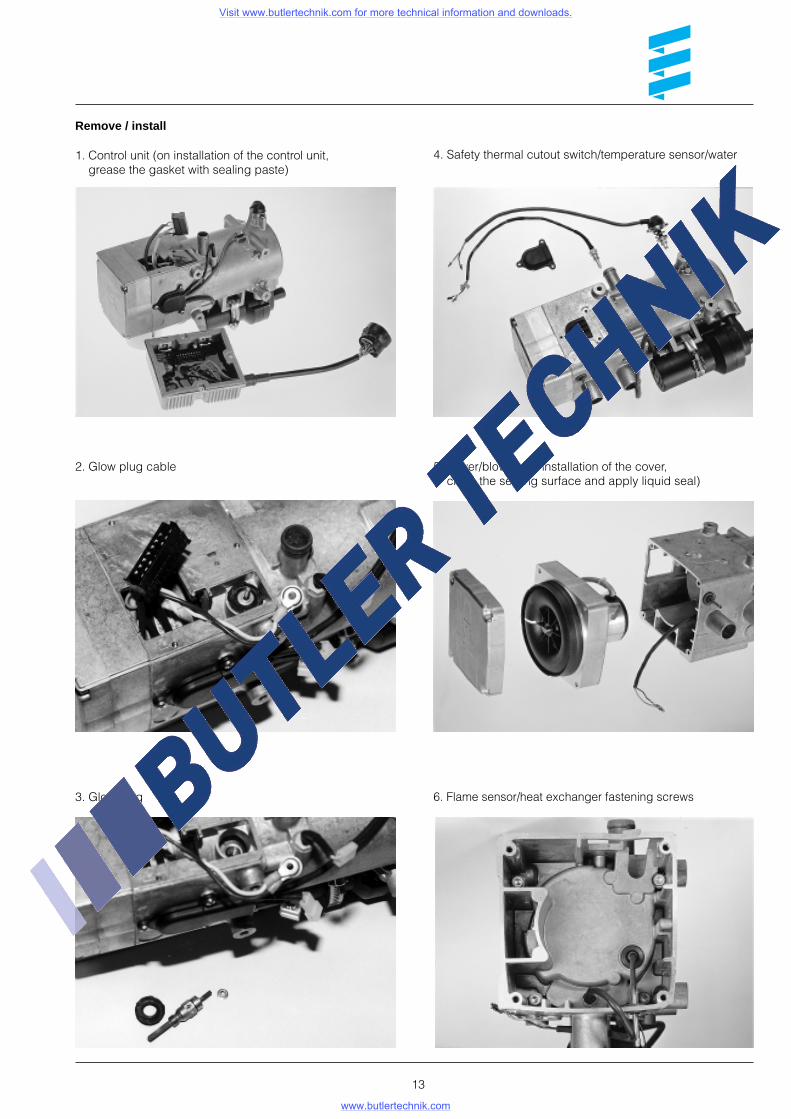
Remove / install
13
1. Control unit (on installation of the control unit, grease the gasket with sealing paste)
4. Safety thermal cutout switch/temperature sensor/water
3. Glow plug 6. Flame sensor/heat exchanger fastening screws
5. Cover/blower (on installation of the cover, clean the sealing surface and apply liquid seal)
2. Glow plug cable
Visit www.butlertechnik.com for more technical information and downloads.
www.butlertechnik.com

7. Housing including heat exchanger, dismantled 10. Heat exchanger
9. Burner, dismantled
8. Burner 11. Heat exchanger, dismantled
14
Visit www.butlertechnik.com for more technical information and downloads.
www.butlertechnik.com