Watchdog Super Elite - go4b.com · Watchdog™ Super Elite BUCKET ELEVATOR & BELT CONVEYOR HAZARD...
32
www.go4b.com/usa Watchdog ™ Super Elite BUCKET ELEVATOR & BELT CONVEYOR HAZARD MONITORING SYSTEM SENSOR WIRING DIAGRAMS Part No.’s - WDC4V4C, WDC4V46C C US ® Operation Manual Supplement
Transcript of Watchdog Super Elite - go4b.com · Watchdog™ Super Elite BUCKET ELEVATOR & BELT CONVEYOR HAZARD...

www.go4b.com/usa
Watchdog™ Super EliteBUCKET ELEVATOR & BELT CONVEYORHAZARD MONITORING SYSTEM
SENSOR WIRING DIAGRAMSPart No.’s - WDC4V4C, WDC4V46C
C US
®
Operation Manual Supplement
Exposed moving parts will cause severe injury or death.
Lockout power before removing cover or inspection door.
DANGER
Rotating parts can crush, cut and entangle.Do NOT operate with guard removed.Lockout power before removing guard or servicing.
WARNING

CUSTOMER SAFETY RESPONSIBILITIES Page 4 - 5
ELECTRICAL CONNECTION Page 6 - 7
PRE-SET PROFILES Page 8
BUCKET ELEVATOR LEG WIRING DIAGRAMS
- Typical Sensor Placement for Bucket Elevators Page 9
1. WDC3 to WDC4 Sensor Wiring Diagram Page 10
2. Sensor Wiring Diagram Profile with Touchswitches Page 11
3. Sensor Wiring Diagram Profile with Rub Blocks Page 12
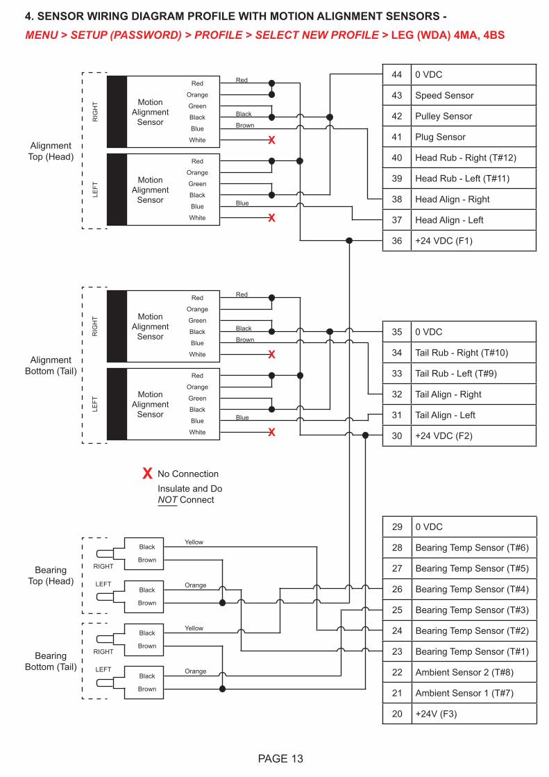
4. Sensor Wiring Diagram Profile with Motion Alignment Sensors Page 13
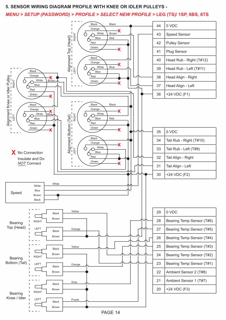
5. Sensor Wiring Diagram Profile with Knee or Idler Pulleys Page 14
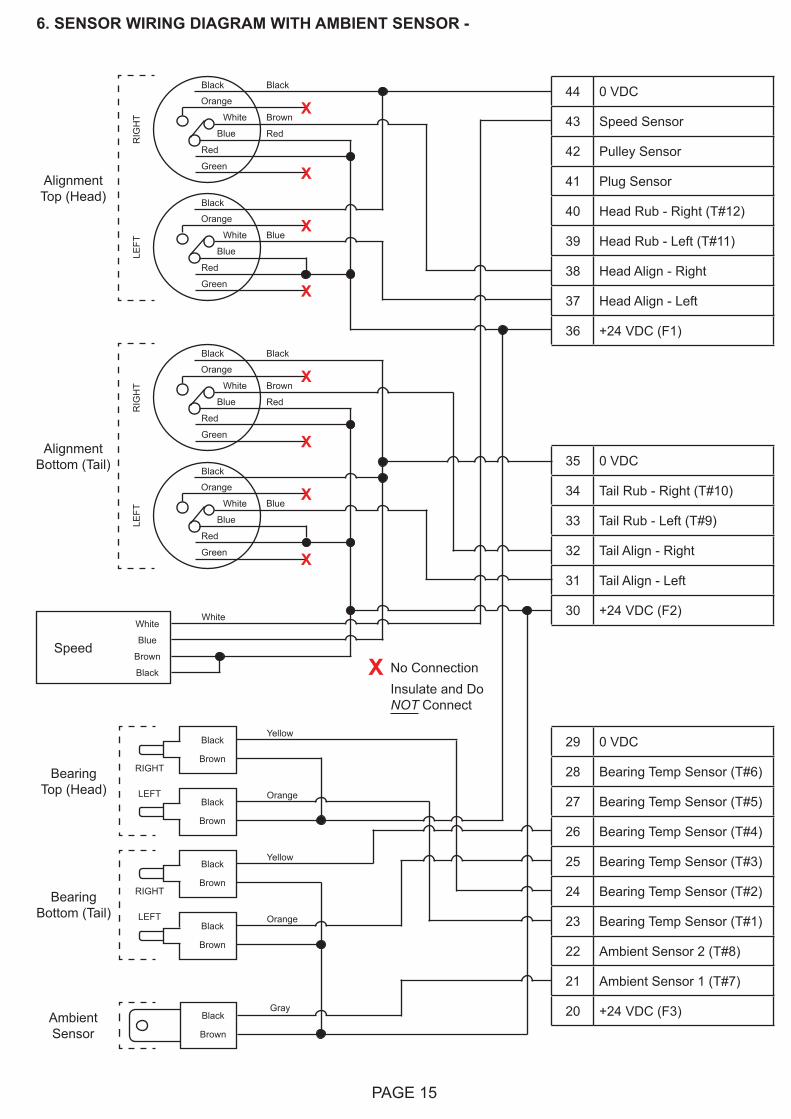
6. Sensor Wiring Diagram with Ambient Sensor Page 15
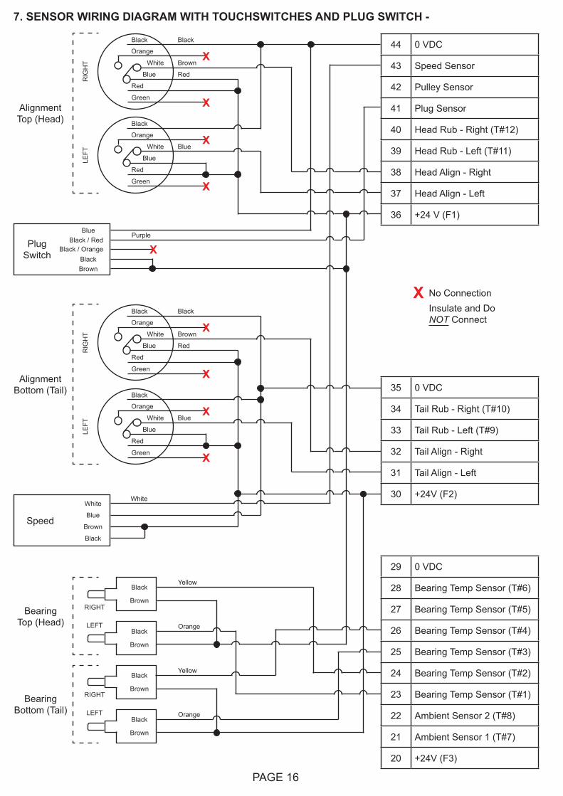
7. Sensor Wiring Diagram with Touchswitches and Plug Switch Page 16
8. Sensor Wiring Diagram with Rub Blocks and Plug Switch Page 17
9. Sensor Wiring Diagram with Motion Alignment Sensors and Plug Switch Page 18
10. Sensor Wiring Diagram with Motion Alignments Sensors, Plug Switch and Head Pulley Sensors Page 19
11. Sensor Wiring Diagram with Touchswitches and Differential Speed Page 20
12. Sensor Wiring Diagram with Touchswitches, Differential Speed and Plug Switch Page 21
ENCLOSED BELT CONVEYOR WIRING DIAGRAMS
- Typical Sensor Placement for Enclosed Belt Conveyors Page 22
13. Sensor Wiring Diagram with 6 Rub Blocks, 4 Bearing Temperature Sensors and 2 Lug Style tail Pulley alignment Sensors
Page 23
14. Sensor Wiring Diagram with Touchswitches, 4 Bearing Temperature Sensors and 2 Lug Style tail Pulley alignment Sensors
Page 24
DRAG CHAIN CONVEYOR WIRING DIAGRAMS
- Typical Sensor Placement for Drag Chain Conveyors Page 26
15. Sensor Wiring Diagram for Slack Chain Detection with Plug Switch Page 27
16. Sensor Wiring Diagram for Slack Chain Detection without Plug Switch Page 28
PRODUCT WARRANTY Page 31
TABLE OF CONTENTS

PAGE 4
Dear 4B Customer:
Congratulations on your purchase. 4B appreciates your business and is pleased you have chosen our products to meet your needs.
Please read in its entirety and understand the literature accompanying the product before you place the product into service. Please read the safety precautions carefully before operating the product. With each product you purchase from 4B, there are some basic but important safety considerations you must follow to be sure your purchase is permitted to perform its design function and operate properly and safely, giving you many years of reliable service. Please read and understand the Customer Safety Responsibilities listed below. Failure to follow this safety directive and the Operation Manuals and other material furnished or referenced, may result in serious injury or death.
SAFETY NOTICE TO OUR CUSTOMERS
A. In order to maximize efficiency and safety, selecting the right equipment for each operation is vital. The proper installation of the equipment, and regular maintenance and inspection is equally important in continuing the proper operation and safety of the product. The proper installation and maintenance of all our products is the responsibility of the user unless you have asked 4B to perform these tasks.
B. All installation and wiring must be in accordance with Local and National Electrical Codes and other standards applicable to your industry. (Please see the article “Hazard Monitoring Equipment Selection, Installation and Maintenance” at www.go4b.com.) The installation of the wiring should be undertaken by an experienced and qualified professional electrician. Failure to correctly wire any product and/or machinery can result in the product or machine failing to operate as intended, and can defeat its design function.
C. Periodic inspection by a qualified person will help assure your 4B product is performing properly. 4B recommends a documented inspection at least annually and more frequently under high use conditions.
D. Please see the last page of this manual for all warranty information regarding this product.
CUSTOMER SAFETY RESPONSIBILITIES
1. READ ALL LITERATURE PROVIDED WITH YOUR PRODUCT
Please read all user, instruction and safety manuals to ensure that you understand your product operation and are able to safely and effectively use this product.
2. YOU BEST UNDERSTAND YOUR NEEDS
Every customer and operation is unique, and only you best know the specific needs and capabilities of your operation. Please call the 24-hour hotline at 309-698-5611 for assistance with any questions about the performance of products purchased from 4B. 4B is happy to discuss product performance with you at any time.

PAGE 5
3. SELECT A QUALIFIED AND COMPETENT INSTALLER
Correct installation of the product is important for safety and performance. If you have not asked 4B to perform the installation of the unit on your behalf, it is critical for the safety of your operation and those who may perform work on your operation that you select a qualified and competent electrical installer to undertake the installation. The product must be installed properly to perform its designed functions. The installer should be qualified, trained, and competent to perform the installation in accordance with Local and National Electrical Codes, all relevant OSHA Regulations, as well as any of your own standards and preventive maintenance requirements, and other product installation information supplied with the product. You should be prepared to provide the installer with all necessary installation information to assist in the installation.
4. ESTABLISH AND FOLLOW A REGULAR MAINTENANCE AND INSPECTION SCHEDULE FOR YOUR 4B PRODUCTS
You should develop a proper maintenance and inspection program to confirm that your system is in good working order at all times. You will be in the best position to determine the appropriate frequency for inspection. Many different factors known to the user will assist you in deciding the frequency of inspection. These factors may include but are not limited to weather conditions; construction work at the facility; hours of operation; animal or insect infestation; and the real-world experience of knowing how your employees perform their jobs. The personnel or person you select to install, operate, maintain, inspect or perform any work whatsoever, should be trained and qualified to perform these important functions. Complete and accurate records of the maintenance and inspection process should be created and retained by you at all times.
5. RETAIN AND REFER TO THE OPERATION MANUAL FOR 4B’S SUGGESTED MAINTENANCE AND INSPECTION RECOMMENDATIONS
As all operations are different, please understand that your specific operation may require additional adjustments in the maintenance and inspection process essential to permit the monitoring device to perform its intended function. Retain the Operation Manual and other important maintenance and service documents provided by 4B and have them readily available for people servicing your 4B equipment. Should you have any questions, please call the free 24-hour hotline number (309-698-5611).
6. SERVICE REQUEST
If you have questions or comments about the operation of your unit or require the unit to be serviced please contact the 4B location who supplied the product or send your request via fax (309-698-5615) or call us via our 24-hour hotline number in the USA (309-698-5611). Please have available product part numbers, serial numbers, and approximate date of installation.
PAGE 6
ELECTRICAL CONNECTIONAll wiring must be in accordance with local and national electrical codes and should be undertaken by an experienced and qualified electrician.
Always use dust/liquid tight flexible metal conduit with approved fittings to protect the sensor cables. Use rigid metal conduit to protect the cables from the sensors to the control unit. Conduit systems can channel water due to ingress and condensation directly to sensors and sensor connections which over time will adversely affect the performance of the system. As such, the installation of low point conduit drains is recommended for all sensors.
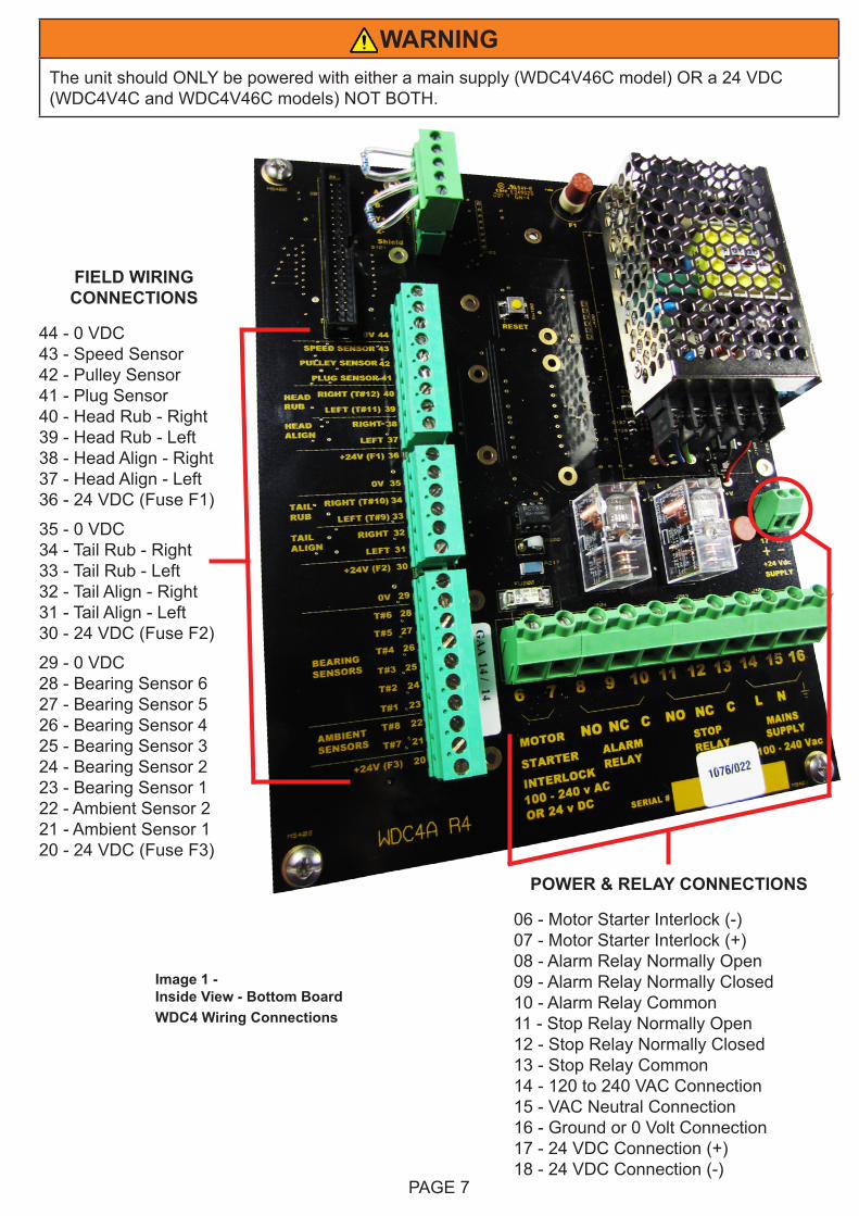
All electrical connections are made via 3 sets of terminals provided as shown in image 1.
FUSE RATINGS -In order to maintain the product certification, all fuses MUST be replaced with equivalent fuses at the same rating. Failure to do so will invalidate the certification and any warranties which may exist.
Model WDC4V4C -
• F1, F2, F3, F5 200 mA maximum.• F1 to F3 are used to limit the current available to the sensor inputs.• F5 is used to limit the current available to the internal electronics.• F6 is not used.
Model WDC4V46C -
• F1 to F3 2 amp maximum, used to limit the current available to the sensor inputs.• F5 200 mA, used to limit the current available to the internal electronics.• F6 2 amp maximum, used to protect the AC power supply.
NOTERecommended cable type is Belden 5508FE with 10 conductors each 22 AWG, shielded. Overall outer diameter is 0.23 inches. Belden 5508FE wire colors are used in all of the sensor wiring diagrams
NOTETo calibrate speed and utilize the Watchdog’s built-in alarm and shut-down capabilities, a motor interlock (run) signal is required. For typical motor interlock wiring examples, review the wiring diagrams for terminals 6 & 7 in the WDC4 manual (section 9).
PAGE 7
WARNINGThe unit should ONLY be powered with either a main supply (WDC4V46C model) OR a 24 VDC (WDC4V4C and WDC4V46C models) NOT BOTH.
FIELD WIRING CONNECTIONS
44 - 0 VDC43 - Speed Sensor42 - Pulley Sensor41 - Plug Sensor40 - Head Rub - Right39 - Head Rub - Left38 - Head Align - Right37 - Head Align - Left36 - 24 VDC (Fuse F1)
35 - 0 VDC34 - Tail Rub - Right33 - Tail Rub - Left32 - Tail Align - Right31 - Tail Align - Left30 - 24 VDC (Fuse F2)
29 - 0 VDC28 - Bearing Sensor 627 - Bearing Sensor 526 - Bearing Sensor 425 - Bearing Sensor 324 - Bearing Sensor 223 - Bearing Sensor 122 - Ambient Sensor 221 - Ambient Sensor 120 - 24 VDC (Fuse F3)
POWER & RELAY CONNECTIONS
06 - Motor Starter Interlock (-)07 - Motor Starter Interlock (+)08 - Alarm Relay Normally Open09 - Alarm Relay Normally Closed10 - Alarm Relay Common11 - Stop Relay Normally Open12 - Stop Relay Normally Closed13 - Stop Relay Common14 - 120 to 240 VAC Connection15 - VAC Neutral Connection16 - Ground or 0 Volt Connection17 - 24 VDC Connection (+)18 - 24 VDC Connection (-)
Image 1 -Inside View - Bottom BoardWDC4 Wiring Connections
PAGE 8
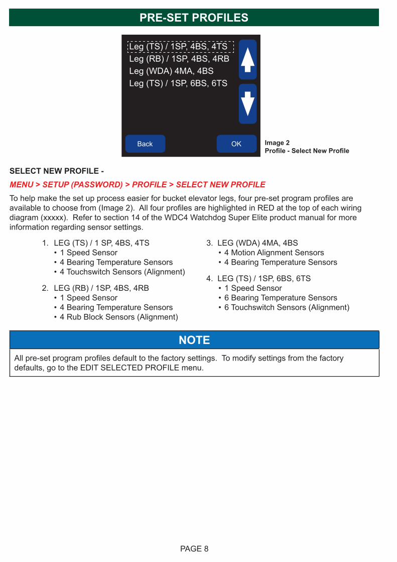
Back OK Image 2Profile - Select New Profile
Leg (TS) / 1SP, 4BS, 4TSLeg (RB) / 1SP, 4BS, 4RBLeg (WDA) 4MA, 4BSLeg (TS) / 1SP, 6BS, 6TS
SELECT NEW PROFILE - MENU > SETUP (PASSWORD) > PROFILE > SELECT NEW PROFILETo help make the set up process easier for bucket elevator legs, four pre-set program profiles are available to choose from (Image 2). All four profiles are highlighted in RED at the top of each wiring diagram (xxxxx). Refer to section 14 of the WDC4 Watchdog Super Elite product manual for more information regarding sensor settings.
NOTEAll pre-set program profiles default to the factory settings. To modify settings from the factory defaults, go to the EDIT SELECTED PROFILE menu.
1. LEG (TS) / 1 SP, 4BS, 4TS• 1 Speed Sensor• 4 Bearing Temperature Sensors• 4 Touchswitch Sensors (Alignment)
2. LEG (RB) / 1SP, 4BS, 4RB• 1 Speed Sensor• 4 Bearing Temperature Sensors• 4 Rub Block Sensors (Alignment)
3. LEG (WDA) 4MA, 4BS• 4 Motion Alignment Sensors• 4 Bearing Temperature Sensors
4. LEG (TS) / 1SP, 6BS, 6TS• 1 Speed Sensor• 6 Bearing Temperature Sensors• 6 Touchswitch Sensors (Alignment)
PRE-SET PROFILES
PAGE 9
1
2
2
3
3
4
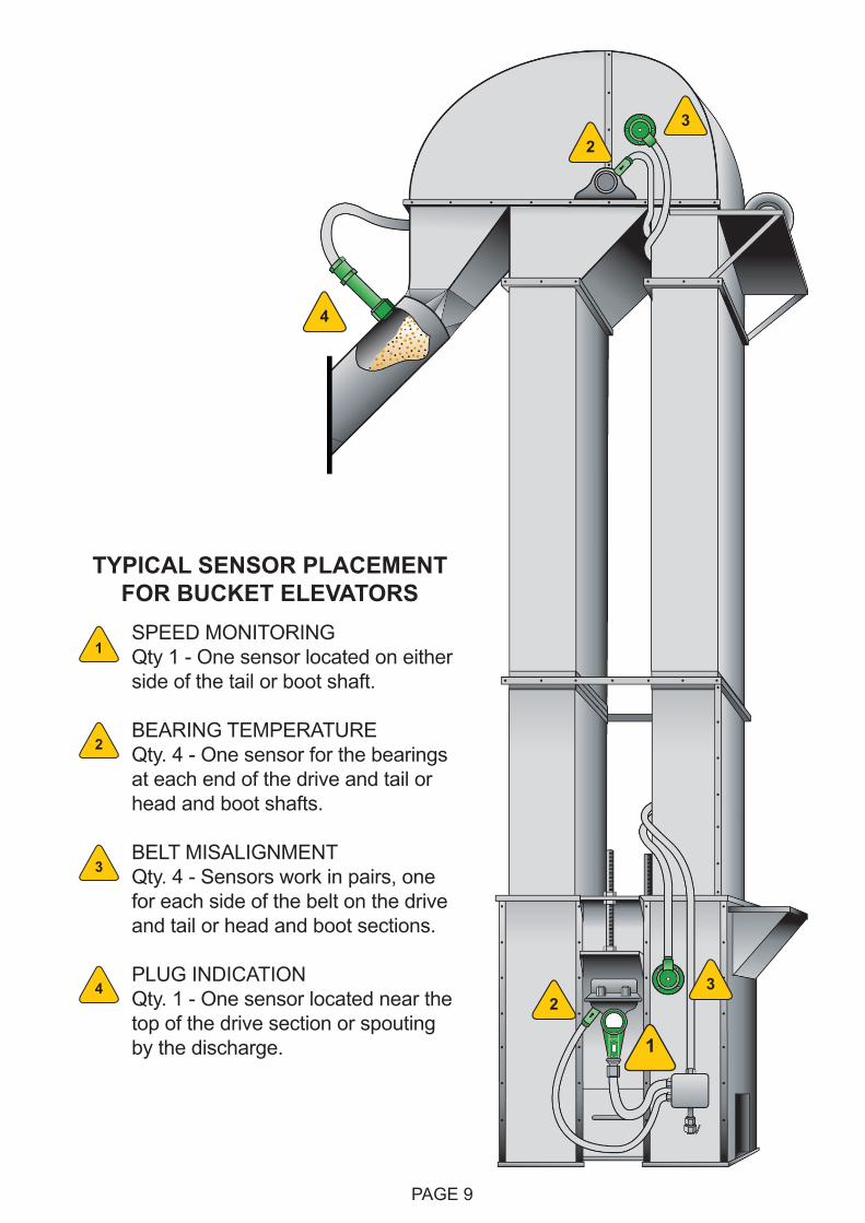
SPEED MONITORING Qty 1 - One sensor located on either side of the tail or boot shaft.
BEARING TEMPERATURE Qty. 4 - One sensor for the bearings at each end of the drive and tail or head and boot shafts.
BELT MISALIGNMENT Qty. 4 - Sensors work in pairs, one for each side of the belt on the drive and tail or head and boot sections.
PLUG INDICATION Qty. 1 - One sensor located near the top of the drive section or spouting by the discharge.
1
2
3
4
TYPICAL SENSOR PLACEMENT FOR BUCKET ELEVATORS
PAGE 10
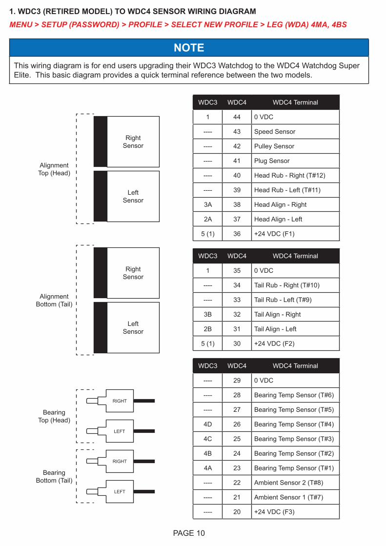
1. WDC3 (RETIRED MODEL) TO WDC4 SENSOR WIRING DIAGRAMMENU > SETUP (PASSWORD) > PROFILE > SELECT NEW PROFILE > LEG (WDA) 4MA, 4BS
Alignment Top (Head)
RightSensor
LeftSensor
Alignment Bottom (Tail)
RightSensor
LeftSensor
WDC3 WDC4 WDC4 Terminal
1 44 0 VDC
---- 43 Speed Sensor
---- 42 Pulley Sensor
---- 41 Plug Sensor
---- 40 Head Rub - Right (T#12)
---- 39 Head Rub - Left (T#11)
3A 38 Head Align - Right
2A 37 Head Align - Left
5 (1) 36 +24 VDC (F1)
WDC3 WDC4 WDC4 Terminal
1 35 0 VDC
---- 34 Tail Rub - Right (T#10)
---- 33 Tail Rub - Left (T#9)
3B 32 Tail Align - Right
2B 31 Tail Align - Left
5 (1) 30 +24 VDC (F2)
WDC3 WDC4 WDC4 Terminal
---- 29 0 VDC
---- 28 Bearing Temp Sensor (T#6)
---- 27 Bearing Temp Sensor (T#5)
4D 26 Bearing Temp Sensor (T#4)
4C 25 Bearing Temp Sensor (T#3)
4B 24 Bearing Temp Sensor (T#2)
4A 23 Bearing Temp Sensor (T#1)
---- 22 Ambient Sensor 2 (T#8)
---- 21 Ambient Sensor 1 (T#7)
---- 20 +24 VDC (F3)
Bearing Bottom (Tail)
Bearing Top (Head)
RIGHT
LEFT
RIGHT
LEFT
NOTEThis wiring diagram is for end users upgrading their WDC3 Watchdog to the WDC4 Watchdog Super Elite. This basic diagram provides a quick terminal reference between the two models.
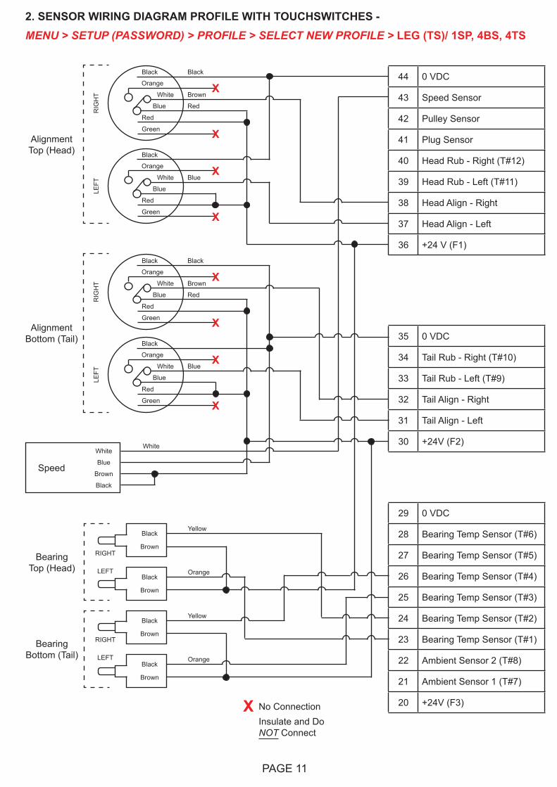
2. SENSOR WIRING DIAGRAM PROFILE WITH TOUCHSWITCHES - MENU > SETUP (PASSWORD) > PROFILE > SELECT NEW PROFILE > LEG (TS)/ 1SP, 4BS, 4TS
44 0 VDC
43 Speed Sensor
42 Pulley Sensor
41 Plug Sensor
40 Head Rub - Right (T#12)
39 Head Rub - Left (T#11)
38 Head Align - Right
37 Head Align - Left
36 +24 V (F1)
35 0 VDC
34 Tail Rub - Right (T#10)
33 Tail Rub - Left (T#9)
32 Tail Align - Right
31 Tail Align - Left
30 +24V (F2)White
Blue
Brown
Black
White
Speed
Alignment Top (Head)
Black
Brown
RedBlue
X
X
RIG
HT
Orange
Black
White
Red
Green
Blue
Blue
X
X
LEFT
Orange
Black
White
Red
Green
Alignment Bottom (Tail)
Black
Brown
RedBlue
X
X
RIG
HT
Orange
Black
White
Red
Green
Blue
Blue
X
X
LEFT
Orange
Black
White
Red
Green
29 0 VDC
28 Bearing Temp Sensor (T#6)
27 Bearing Temp Sensor (T#5)
26 Bearing Temp Sensor (T#4)
25 Bearing Temp Sensor (T#3)
24 Bearing Temp Sensor (T#2)
23 Bearing Temp Sensor (T#1)
22 Ambient Sensor 2 (T#8)
21 Ambient Sensor 1 (T#7)
20 +24V (F3)
Black
Brown
Black
Brown
Black
Brown
Black
Brown
Yellow
Orange
Yellow
Orange
Bearing Bottom (Tail)
Bearing Top (Head)
RIGHT
LEFT
RIGHT
LEFT
PAGE 11
X No ConnectionInsulate and Do NOT Connect
PAGE 12
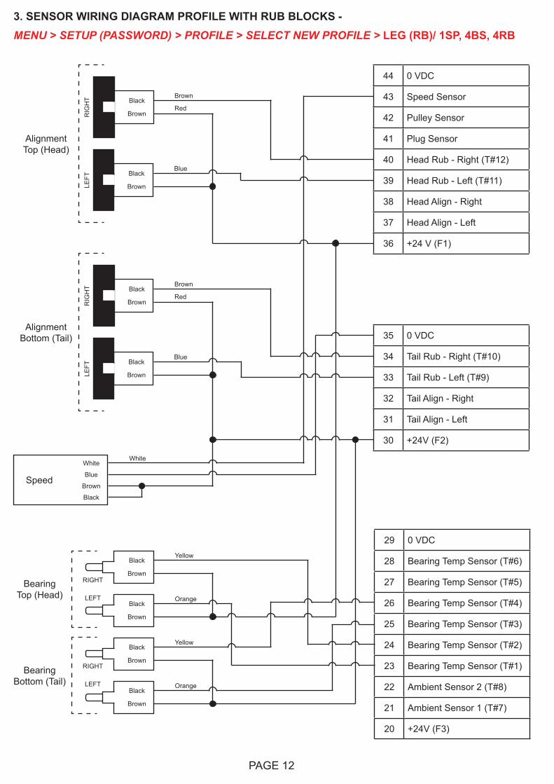
3. SENSOR WIRING DIAGRAM PROFILE WITH RUB BLOCKS -MENU > SETUP (PASSWORD) > PROFILE > SELECT NEW PROFILE > LEG (RB)/ 1SP, 4BS, 4RB
44 0 VDC
43 Speed Sensor
42 Pulley Sensor
41 Plug Sensor
40 Head Rub - Right (T#12)
39 Head Rub - Left (T#11)
38 Head Align - Right
37 Head Align - Left
36 +24 V (F1)
35 0 VDC
34 Tail Rub - Right (T#10)
33 Tail Rub - Left (T#9)
32 Tail Align - Right
31 Tail Align - Left
30 +24V (F2)
White
Blue
Brown
Black
White
Speed
Alignment Top (Head)
BrownBlack
Brown
BlueBlack
Brown
Alignment Bottom (Tail)
BrownBlack
Brown
BlueBlack
Brown
RIG
HT
LEFT
RIG
HT
LEFT
Red
Red
29 0 VDC
28 Bearing Temp Sensor (T#6)
27 Bearing Temp Sensor (T#5)
26 Bearing Temp Sensor (T#4)
25 Bearing Temp Sensor (T#3)
24 Bearing Temp Sensor (T#2)
23 Bearing Temp Sensor (T#1)
22 Ambient Sensor 2 (T#8)
21 Ambient Sensor 1 (T#7)
20 +24V (F3)
Black
Brown
Black
Brown
Black
Brown
Black
Brown
Yellow
Orange
Yellow
Orange
Bearing Bottom (Tail)
Bearing Top (Head)
RIGHT
LEFT
RIGHT
LEFT
PAGE 13
4. SENSOR WIRING DIAGRAM PROFILE WITH MOTION ALIGNMENT SENSORS -MENU > SETUP (PASSWORD) > PROFILE > SELECT NEW PROFILE > LEG (WDA) 4MA, 4BS
Alignment Top (Head)
Green
Black
Blue
White
MotionAlignment
Sensor
Red
Orange
Green
Black
Blue
White
MotionAlignment
Sensor
Red
Orange
Alignment Bottom (Tail)
Green
Black
Blue
White
MotionAlignment
Sensor
Red
Orange
Green
Black
Blue
White
MotionAlignment
Sensor
Red
Orange
44 0 VDC
43 Speed Sensor
42 Pulley Sensor
41 Plug Sensor
40 Head Rub - Right (T#12)
39 Head Rub - Left (T#11)
38 Head Align - Right
37 Head Align - Left
36 +24 VDC (F1)
35 0 VDC
34 Tail Rub - Right (T#10)
33 Tail Rub - Left (T#9)
32 Tail Align - Right
31 Tail Align - Left
30 +24 VDC (F2)
RIG
HT
LEFT
RIG
HT
LEFT
Red
Black
Brown
Blue
Red
Brown
Black
Blue
X
X
X
X
29 0 VDC
28 Bearing Temp Sensor (T#6)
27 Bearing Temp Sensor (T#5)
26 Bearing Temp Sensor (T#4)
25 Bearing Temp Sensor (T#3)
24 Bearing Temp Sensor (T#2)
23 Bearing Temp Sensor (T#1)
22 Ambient Sensor 2 (T#8)
21 Ambient Sensor 1 (T#7)
20 +24V (F3)
Black
Brown
Black
Brown
Black
Brown
Black
Brown
Yellow
Orange
Yellow
Orange
Bearing Bottom (Tail)
Bearing Top (Head)
RIGHT
LEFT
RIGHT
LEFT
X No ConnectionInsulate and Do NOT Connect
PAGE 14
5. SENSOR WIRING DIAGRAM PROFILE WITH KNEE OR IDLER PULLEYS - MENU > SETUP (PASSWORD) > PROFILE > SELECT NEW PROFILE > LEG (TS)/ 1SP, 6BS, 6TS
44 0 VDC
43 Speed Sensor
42 Pulley Sensor
41 Plug Sensor
40 Head Rub - Right (T#12)
39 Head Rub - Left (T#11)
38 Head Align - Right
37 Head Align - Left
36 +24 VDC (F1)
35 0 VDC
34 Tail Rub - Right (T#10)
33 Tail Rub - Left (T#9)
32 Tail Align - Right
31 Tail Align - Left
30 +24 VDC (F2)
29 0 VDC
28 Bearing Temp Sensor (T#6)
27 Bearing Temp Sensor (T#5)
26 Bearing Temp Sensor (T#4)
25 Bearing Temp Sensor (T#3)
24 Bearing Temp Sensor (T#2)
23 Bearing Temp Sensor (T#1)
22 Ambient Sensor 2 (T#8)
21 Ambient Sensor 1 (T#7)
20 +24 VDC (F3)
Black
Brown
Black
Brown
Yellow
Orange
Bearing Bottom (Tail)
Black
Brown
Black
Brown
Yellow
Orange
Bearing Top (Head)
Black
Brown
Black
Brown
Gray
Purple
Bearing Knee / Idler
White
Blue
Brown
Black
White
Speed
Black
Brown
RedBlue
X
X
RIG
HT
Orange
Black
White
Red
Green
Blue
Blue
X
X
LEFT
Orange
Black
White
Red
Green
Alig
nmen
t Bot
tom
(Tai
l)A
lignm
ent T
op (H
ead)
Alig
nmen
t Kne
e or
Idle
r Pul
ley
Black
Brown
RedBlue
X
X
RIG
HT
Orange
Black
White
Red
Green
Blue
Blue
X
X
LEFT
Orange
Black
White
Red
Green
Blue
X
X
RIG
HT
Orange
Black
White
Red
Green
Blue
X
X
LEFT
Orange
Black
White
Red
Green
RIGHT
LEFT
RIGHT
LEFT
RIGHT
LEFT
X No ConnectionInsulate and Do NOT Connect
PAGE 15
6. SENSOR WIRING DIAGRAM WITH AMBIENT SENSOR -
44 0 VDC
43 Speed Sensor
42 Pulley Sensor
41 Plug Sensor
40 Head Rub - Right (T#12)
39 Head Rub - Left (T#11)
38 Head Align - Right
37 Head Align - Left
36 +24 VDC (F1)
35 0 VDC
34 Tail Rub - Right (T#10)
33 Tail Rub - Left (T#9)
32 Tail Align - Right
31 Tail Align - Left
30 +24 VDC (F2)
29 0 VDC
28 Bearing Temp Sensor (T#6)
27 Bearing Temp Sensor (T#5)
26 Bearing Temp Sensor (T#4)
25 Bearing Temp Sensor (T#3)
24 Bearing Temp Sensor (T#2)
23 Bearing Temp Sensor (T#1)
22 Ambient Sensor 2 (T#8)
21 Ambient Sensor 1 (T#7)
20 +24 VDC (F3)
White
Blue
Brown
Black
White
Speed
Black
BrownAmbientSensor
Black
Brown
Black
Brown
Black
Brown
Black
Brown
Yellow
Orange
Yellow
Orange
Bearing Bottom (Tail)
Bearing Top (Head)
Alignment Top (Head)
Black
Brown
RedBlue
X
X
RIG
HT
Orange
Black
White
Red
Green
Blue
Blue
X
X
LEFT
Orange
Black
White
Red
Green
Alignment Bottom (Tail)
Black
Brown
RedBlue
X
X
RIG
HT
Orange
Black
White
Red
Green
Blue
Blue
X
X
LEFT
Orange
Black
White
Red
Green
Gray
RIGHT
LEFT
RIGHT
LEFT
X No ConnectionInsulate and Do NOT Connect
PAGE 16
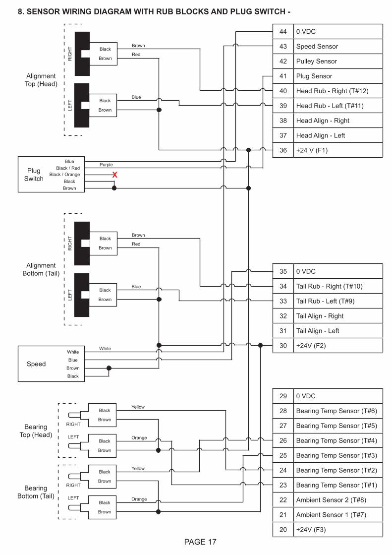
7. SENSOR WIRING DIAGRAM WITH TOUCHSWITCHES AND PLUG SWITCH -
44 0 VDC
43 Speed Sensor
42 Pulley Sensor
41 Plug Sensor
40 Head Rub - Right (T#12)
39 Head Rub - Left (T#11)
38 Head Align - Right
37 Head Align - Left
36 +24 V (F1)
35 0 VDC
34 Tail Rub - Right (T#10)
33 Tail Rub - Left (T#9)
32 Tail Align - Right
31 Tail Align - Left
30 +24V (F2)
29 0 VDC
28 Bearing Temp Sensor (T#6)
27 Bearing Temp Sensor (T#5)
26 Bearing Temp Sensor (T#4)
25 Bearing Temp Sensor (T#3)
24 Bearing Temp Sensor (T#2)
23 Bearing Temp Sensor (T#1)
22 Ambient Sensor 2 (T#8)
21 Ambient Sensor 1 (T#7)
20 +24V (F3)
White
Blue
Brown
Black
White
Speed
Black
Brown
Black
Brown
Black
Brown
Black
Brown
Yellow
Orange
Yellow
Orange
Bearing Bottom (Tail)
Bearing Top (Head)
Alignment Top (Head)
Black
Brown
RedBlue
X
X
RIG
HT
Orange
Black
White
Red
Green
Blue
Blue
X
X
LEFT
Orange
Black
White
Red
Green
Alignment Bottom (Tail)
Black
Brown
RedBlue
X
X
RIG
HT
Orange
Black
White
Red
Green
Blue
Blue
X
X
LEFT
Orange
Black
White
Red
Green
RIGHT
LEFT
RIGHT
LEFT
X No ConnectionInsulate and Do NOT Connect
BlueBlack / Red
BlackBrown
PlugSwitch
Purple
Black / Orange X
PAGE 17
8. SENSOR WIRING DIAGRAM WITH RUB BLOCKS AND PLUG SWITCH -
44 0 VDC
43 Speed Sensor
42 Pulley Sensor
41 Plug Sensor
40 Head Rub - Right (T#12)
39 Head Rub - Left (T#11)
38 Head Align - Right
37 Head Align - Left
36 +24 V (F1)
35 0 VDC
34 Tail Rub - Right (T#10)
33 Tail Rub - Left (T#9)
32 Tail Align - Right
31 Tail Align - Left
30 +24V (F2)White
Blue
Brown
Black
White
Speed
Alignment Top (Head)
BrownBlack
Brown
BlueBlack
Brown
Alignment Bottom (Tail)
BrownBlack
Brown
BlueBlack
Brown
RIG
HT
LEFT
RIG
HT
LEFT
Red
Red
29 0 VDC
28 Bearing Temp Sensor (T#6)
27 Bearing Temp Sensor (T#5)
26 Bearing Temp Sensor (T#4)
25 Bearing Temp Sensor (T#3)
24 Bearing Temp Sensor (T#2)
23 Bearing Temp Sensor (T#1)
22 Ambient Sensor 2 (T#8)
21 Ambient Sensor 1 (T#7)
20 +24V (F3)
Black
Brown
Black
Brown
Black
Brown
Black
Brown
Yellow
Orange
Yellow
Orange
Bearing Bottom (Tail)
Bearing Top (Head)
RIGHT
LEFT
RIGHT
LEFT
BlueBlack / Red
BlackBrown
PlugSwitch
Purple
Black / Orange X
PAGE 18
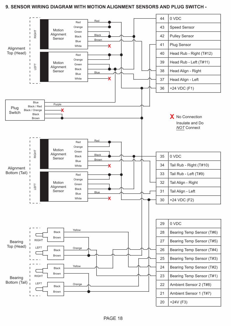
9. SENSOR WIRING DIAGRAM WITH MOTION ALIGNMENT SENSORS AND PLUG SWITCH -
Alignment Top (Head)
Green
Black
Blue
White
MotionAlignment
Sensor
Red
Orange
Green
Black
Blue
White
MotionAlignment
Sensor
Red
Orange
Alignment Bottom (Tail)
Green
Black
Blue
White
MotionAlignment
Sensor
Red
Orange
Green
Black
Blue
White
MotionAlignment
Sensor
Red
Orange
44 0 VDC
43 Speed Sensor
42 Pulley Sensor
41 Plug Sensor
40 Head Rub - Right (T#12)
39 Head Rub - Left (T#11)
38 Head Align - Right
37 Head Align - Left
36 +24 VDC (F1)
35 0 VDC
34 Tail Rub - Right (T#10)
33 Tail Rub - Left (T#9)
32 Tail Align - Right
31 Tail Align - Left
30 +24 VDC (F2)
RIG
HT
LEFT
RIG
HT
LEFT
Red
Black
Brown
Blue
Red
Brown
Black
Blue
X
X
X
X
29 0 VDC
28 Bearing Temp Sensor (T#6)
27 Bearing Temp Sensor (T#5)
26 Bearing Temp Sensor (T#4)
25 Bearing Temp Sensor (T#3)
24 Bearing Temp Sensor (T#2)
23 Bearing Temp Sensor (T#1)
22 Ambient Sensor 2 (T#8)
21 Ambient Sensor 1 (T#7)
20 +24V (F3)
Black
Brown
Black
Brown
Black
Brown
Black
Brown
Yellow
Orange
Yellow
Orange
Bearing Bottom (Tail)
Bearing Top (Head)
RIGHT
LEFT
RIGHT
LEFT
X No ConnectionInsulate and Do NOT Connect
BlueBlack / Red
BlackBrown
PlugSwitch
Purple
Black / Orange X
PAGE 19
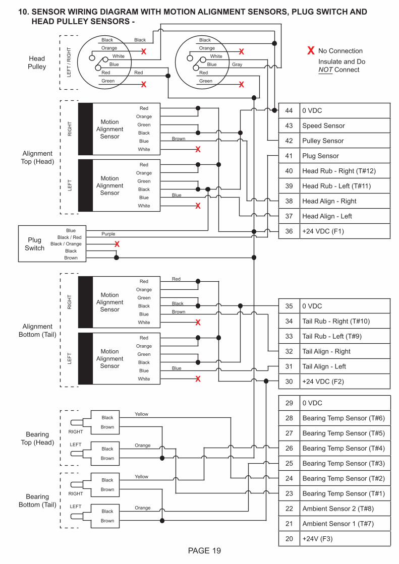
10. SENSOR WIRING DIAGRAM WITH MOTION ALIGNMENT SENSORS, PLUG SWITCH AND HEAD PULLEY SENSORS -
Alignment Top (Head)
Green
Black
Blue
White
MotionAlignment
Sensor
Red
Orange
Green
Black
Blue
White
MotionAlignment
Sensor
Red
Orange
Alignment Bottom (Tail)
Green
Black
Blue
White
MotionAlignment
Sensor
Red
Orange
Green
Black
Blue
White
MotionAlignment
Sensor
Red
Orange
44 0 VDC
43 Speed Sensor
42 Pulley Sensor
41 Plug Sensor
40 Head Rub - Right (T#12)
39 Head Rub - Left (T#11)
38 Head Align - Right
37 Head Align - Left
36 +24 VDC (F1)
35 0 VDC
34 Tail Rub - Right (T#10)
33 Tail Rub - Left (T#9)
32 Tail Align - Right
31 Tail Align - Left
30 +24 VDC (F2)
RIG
HT
LEFT
RIG
HT
LEFT
Brown
Blue
Red
Brown
Black
Blue
X
X
X
X
29 0 VDC
28 Bearing Temp Sensor (T#6)
27 Bearing Temp Sensor (T#5)
26 Bearing Temp Sensor (T#4)
25 Bearing Temp Sensor (T#3)
24 Bearing Temp Sensor (T#2)
23 Bearing Temp Sensor (T#1)
22 Ambient Sensor 2 (T#8)
21 Ambient Sensor 1 (T#7)
20 +24V (F3)
Black
Brown
Black
Brown
Black
Brown
Black
Brown
Yellow
Orange
Yellow
Orange
Bearing Bottom (Tail)
Bearing Top (Head)
RIGHT
LEFT
RIGHT
LEFT
Head Pulley GrayBlue
X
X
Orange
Black
White
Red
Green
Black
Blue
X
X
LEFT
/ R
IGH
T Orange
Black
White
Red
Green
Red
X No ConnectionInsulate and Do NOT Connect
BlueBlack / Red
BlackBrown
PlugSwitch
Purple
Black / Orange X
PAGE 20
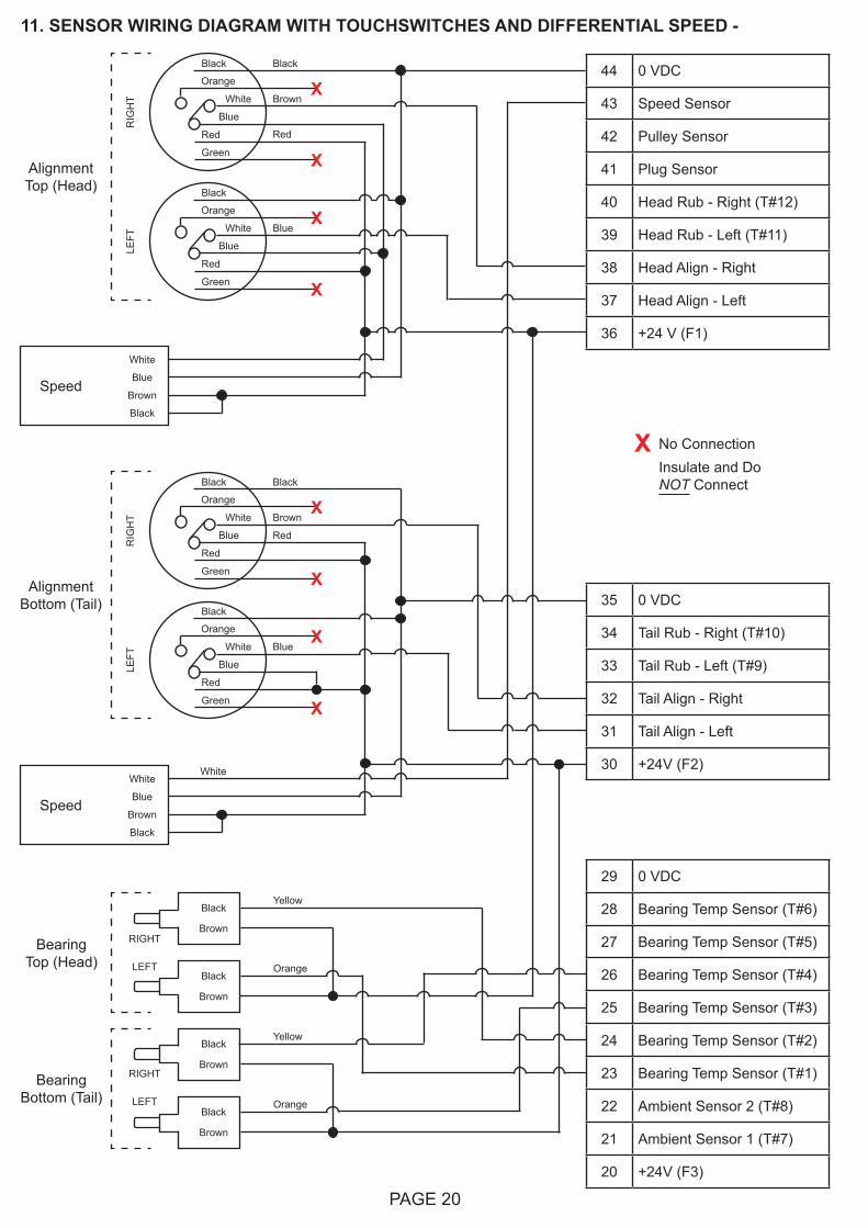
11. SENSOR WIRING DIAGRAM WITH TOUCHSWITCHES AND DIFFERENTIAL SPEED -
44 0 VDC
43 Speed Sensor
42 Pulley Sensor
41 Plug Sensor
40 Head Rub - Right (T#12)
39 Head Rub - Left (T#11)
38 Head Align - Right
37 Head Align - Left
36 +24 V (F1)
35 0 VDC
34 Tail Rub - Right (T#10)
33 Tail Rub - Left (T#9)
32 Tail Align - Right
31 Tail Align - Left
30 +24V (F2)
29 0 VDC
28 Bearing Temp Sensor (T#6)
27 Bearing Temp Sensor (T#5)
26 Bearing Temp Sensor (T#4)
25 Bearing Temp Sensor (T#3)
24 Bearing Temp Sensor (T#2)
23 Bearing Temp Sensor (T#1)
22 Ambient Sensor 2 (T#8)
21 Ambient Sensor 1 (T#7)
20 +24V (F3)
White
Blue
Brown
Black
White
Speed
Black
Brown
Black
Brown
Black
Brown
Black
Brown
Yellow
Orange
Yellow
Orange
Bearing Bottom (Tail)
Bearing Top (Head)
Alignment Top (Head)
Black
Brown
Red
Blue
X
X
RIG
HT
Orange
Black
White
Red
Green
Blue
Blue
X
X
LEFT
Orange
Black
White
Red
Green
Alignment Bottom (Tail)
Black
Brown
RedBlue
X
X
RIG
HT
Orange
Black
White
Red
Green
Blue
Blue
X
X
LEFT
Orange
Black
White
Red
Green
RIGHT
LEFT
RIGHT
LEFT
White
Blue
Brown
Black
Speed
X No ConnectionInsulate and Do NOT Connect
PAGE 21
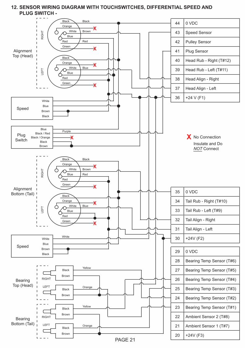
12. SENSOR WIRING DIAGRAM WITH TOUCHSWITCHES, DIFFERENTIAL SPEED AND PLUG SWITCH -
44 0 VDC
43 Speed Sensor
42 Pulley Sensor
41 Plug Sensor
40 Head Rub - Right (T#12)
39 Head Rub - Left (T#11)
38 Head Align - Right
37 Head Align - Left
36 +24 V (F1)
35 0 VDC
34 Tail Rub - Right (T#10)
33 Tail Rub - Left (T#9)
32 Tail Align - Right
31 Tail Align - Left
30 +24V (F2)
29 0 VDC
28 Bearing Temp Sensor (T#6)
27 Bearing Temp Sensor (T#5)
26 Bearing Temp Sensor (T#4)
25 Bearing Temp Sensor (T#3)
24 Bearing Temp Sensor (T#2)
23 Bearing Temp Sensor (T#1)
22 Ambient Sensor 2 (T#8)
21 Ambient Sensor 1 (T#7)
20 +24V (F3)
White
Blue
Brown
Black
White
Speed
Black
Brown
Black
Brown
Black
Brown
Black
Brown
Yellow
Orange
Yellow
Orange
Bearing Bottom (Tail)
Bearing Top (Head)
Alignment Top (Head)
Black
Brown
Red
Blue
X
XR
IGH
T
Orange
Black
White
Red
Green
Blue
Blue
X
X
LEFT
Orange
Black
White
Red
Green
Alignment Bottom (Tail)
Black
Brown
RedBlue
X
X
RIG
HT
Orange
Black
White
Red
Green
Blue
Blue
X
X
LEFT
Orange
Black
White
Red
Green
RIGHT
LEFT
RIGHT
LEFT
White
Blue
Brown
Black
Speed
X No ConnectionInsulate and Do NOT Connect
BlueBlack / Red
BlackBrown
PlugSwitch
Purple
Black / Orange X
PAGE 22
12
23 3
45
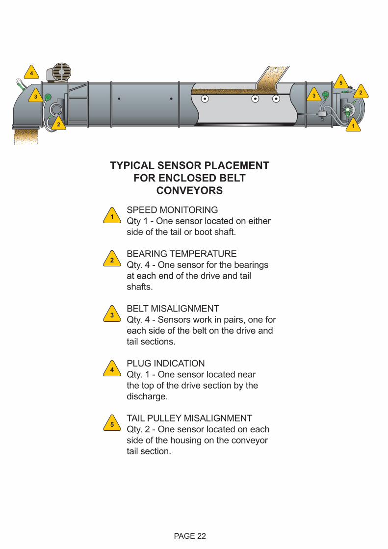
SPEED MONITORING Qty 1 - One sensor located on either side of the tail or boot shaft.
BEARING TEMPERATURE Qty. 4 - One sensor for the bearings at each end of the drive and tail shafts.
BELT MISALIGNMENT Qty. 4 - Sensors work in pairs, one for each side of the belt on the drive and tail sections.
PLUG INDICATION Qty. 1 - One sensor located near the top of the drive section by the discharge.
TAIL PULLEY MISALIGNMENT Qty. 2 - One sensor located on each side of the housing on the conveyor tail section.
1
2
3
4
5
TYPICAL SENSOR PLACEMENT FOR ENCLOSED BELT
CONVEYORS
PAGE 23
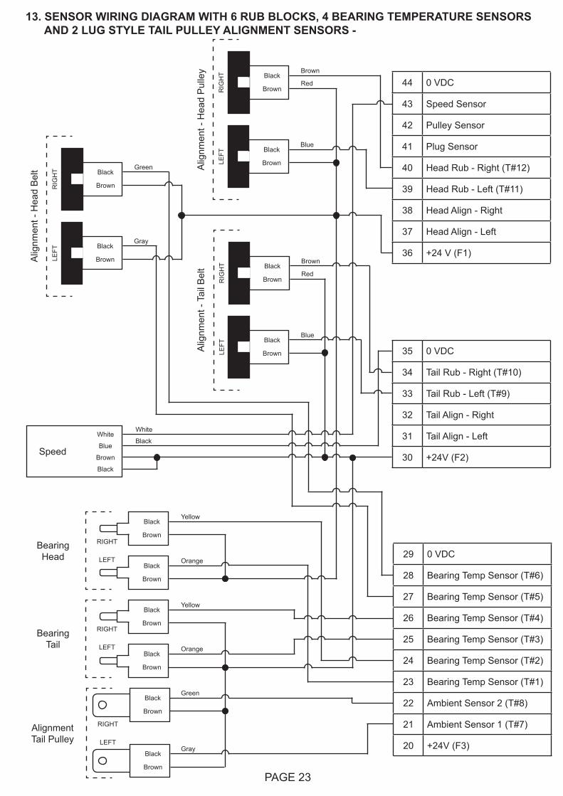
13. SENSOR WIRING DIAGRAM WITH 6 RUB BLOCKS, 4 BEARING TEMPERATURE SENSORS AND 2 LUG STYLE TAIL PULLEY ALIGNMENT SENSORS -
44 0 VDC
43 Speed Sensor
42 Pulley Sensor
41 Plug Sensor
40 Head Rub - Right (T#12)
39 Head Rub - Left (T#11)
38 Head Align - Right
37 Head Align - Left
36 +24 V (F1)
35 0 VDC
34 Tail Rub - Right (T#10)
33 Tail Rub - Left (T#9)
32 Tail Align - Right
31 Tail Align - Left
30 +24V (F2)
White
Blue
Brown
Black
White
Speed
Alig
nmen
t - H
ead
Pul
ley Brown
Black
Brown
BlueBlack
Brown
BrownBlack
Brown
BlueBlack
Brown
RIG
HT
LEFT
RIG
HT
LEFT
Red
Red
29 0 VDC
28 Bearing Temp Sensor (T#6)
27 Bearing Temp Sensor (T#5)
26 Bearing Temp Sensor (T#4)
25 Bearing Temp Sensor (T#3)
24 Bearing Temp Sensor (T#2)
23 Bearing Temp Sensor (T#1)
22 Ambient Sensor 2 (T#8)
21 Ambient Sensor 1 (T#7)
20 +24V (F3)
Black
Brown
Black
Brown
Black
Brown
Black
Brown
Yellow
Orange
Yellow
Orange
Bearing Tail
Bearing Head
RIGHT
LEFT
RIGHT
LEFT
Black
Brown
GreenBlack
Brown
GrayBlack
Brown
RIG
HT
LEFT
Alig
nmen
t - T
ail B
elt
Alig
nmen
t - H
ead
Bel
t
Black
Brown
AlignmentTail Pulley
Green
Gray
Black
RIGHT
LEFT
PAGE 24
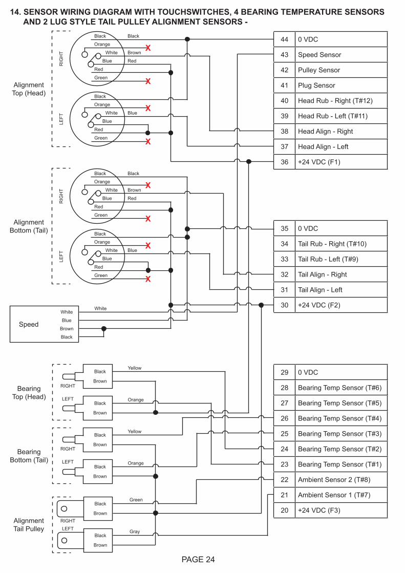
14. SENSOR WIRING DIAGRAM WITH TOUCHSWITCHES, 4 BEARING TEMPERATURE SENSORS AND 2 LUG STYLE TAIL PULLEY ALIGNMENT SENSORS -
44 0 VDC
43 Speed Sensor
42 Pulley Sensor
41 Plug Sensor
40 Head Rub - Right (T#12)
39 Head Rub - Left (T#11)
38 Head Align - Right
37 Head Align - Left
36 +24 VDC (F1)
35 0 VDC
34 Tail Rub - Right (T#10)
33 Tail Rub - Left (T#9)
32 Tail Align - Right
31 Tail Align - Left
30 +24 VDC (F2)
29 0 VDC
28 Bearing Temp Sensor (T#6)
27 Bearing Temp Sensor (T#5)
26 Bearing Temp Sensor (T#4)
25 Bearing Temp Sensor (T#3)
24 Bearing Temp Sensor (T#2)
23 Bearing Temp Sensor (T#1)
22 Ambient Sensor 2 (T#8)
21 Ambient Sensor 1 (T#7)
20 +24 VDC (F3)
White
Blue
Brown
Black
White
Speed
Black
Brown
AlignmentTail Pulley
Black
Brown
Black
Brown
Black
Brown
Black
Brown
Yellow
Orange
Yellow
Orange
Bearing Bottom (Tail)
Bearing Top (Head)
Alignment Top (Head)
Black
Brown
RedBlue
X
X
RIG
HT
Orange
Black
White
Red
Green
Blue
Blue
X
X
LEFT
Orange
Black
White
Red
Green
Alignment Bottom (Tail)
Black
Brown
RedBlue
X
X
RIG
HT
Orange
Black
White
Red
Green
Blue
Blue
X
X
LEFT
Orange
Black
White
Red
Green
Green
RIGHT
LEFT
RIGHT
LEFT
Black
Brown
Gray
RIGHTLEFT

PAGE 25
NOTES
PAGE 26
2
1
4
2
3
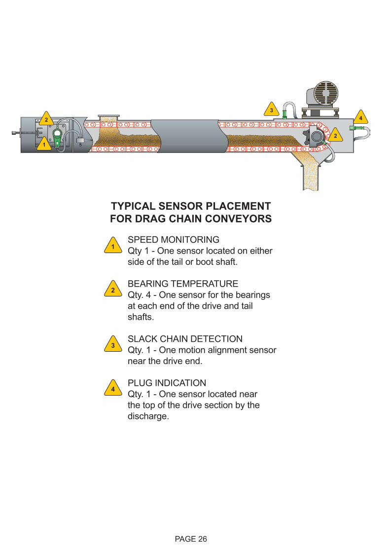
SPEED MONITORING Qty 1 - One sensor located on either side of the tail or boot shaft.
BEARING TEMPERATURE Qty. 4 - One sensor for the bearings at each end of the drive and tail shafts.
SLACK CHAIN DETECTION Qty. 1 - One motion alignment sensor near the drive end.
PLUG INDICATION Qty. 1 - One sensor located near the top of the drive section by the discharge.
1
2
3
4
TYPICAL SENSOR PLACEMENT FOR DRAG CHAIN CONVEYORS
PAGE 27
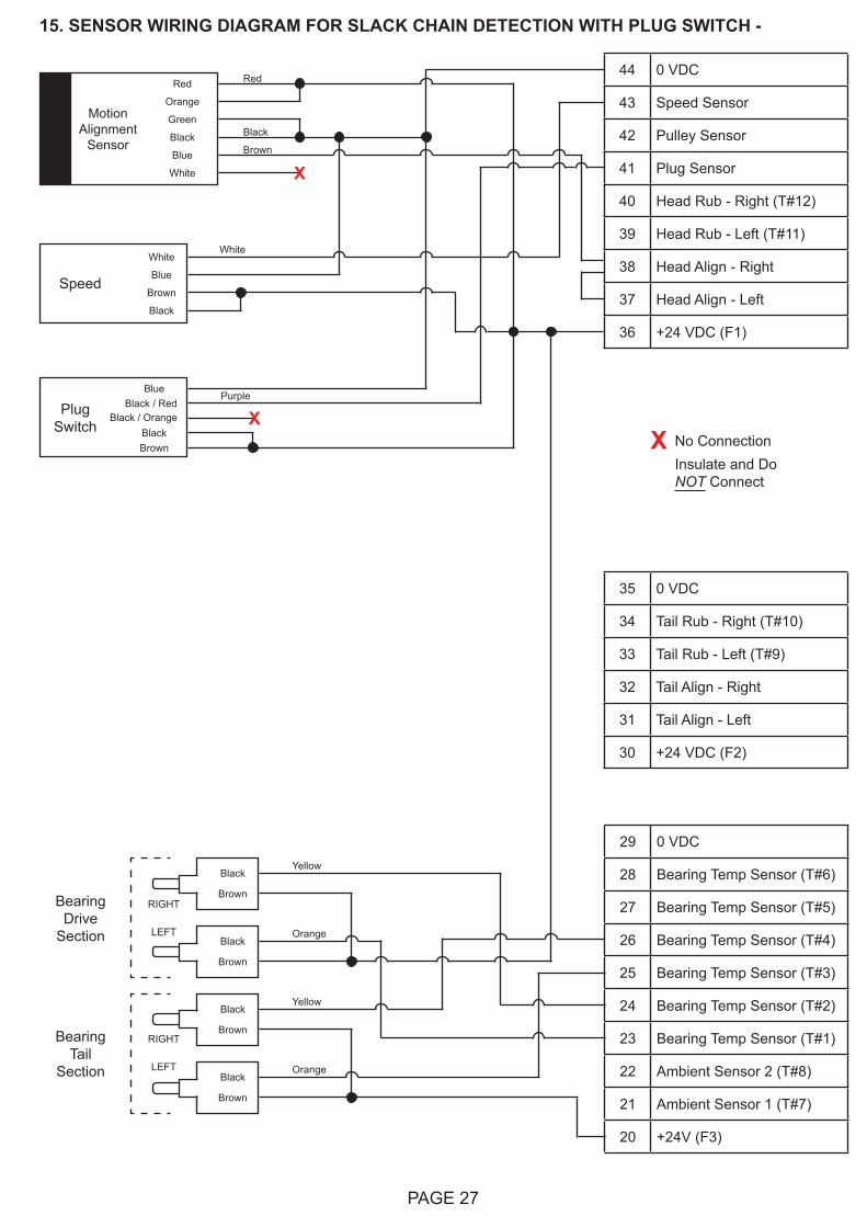
15. SENSOR WIRING DIAGRAM FOR SLACK CHAIN DETECTION WITH PLUG SWITCH -
Green
Black
Blue
White
MotionAlignment
Sensor
Red
Orange
44 0 VDC
43 Speed Sensor
42 Pulley Sensor
41 Plug Sensor
40 Head Rub - Right (T#12)
39 Head Rub - Left (T#11)
38 Head Align - Right
37 Head Align - Left
36 +24 VDC (F1)
35 0 VDC
34 Tail Rub - Right (T#10)
33 Tail Rub - Left (T#9)
32 Tail Align - Right
31 Tail Align - Left
30 +24 VDC (F2)
Red
Black
Brown
X
29 0 VDC
28 Bearing Temp Sensor (T#6)
27 Bearing Temp Sensor (T#5)
26 Bearing Temp Sensor (T#4)
25 Bearing Temp Sensor (T#3)
24 Bearing Temp Sensor (T#2)
23 Bearing Temp Sensor (T#1)
22 Ambient Sensor 2 (T#8)
21 Ambient Sensor 1 (T#7)
20 +24V (F3)
Black
Brown
Black
Brown
Black
Brown
Black
Brown
Yellow
Orange
Yellow
Orange
Bearing Tail
Section
Bearing Drive
Section
RIGHT
LEFT
RIGHT
LEFT
White
Blue
Brown
Black
White
Speed
X No ConnectionInsulate and Do NOT Connect
BlueBlack / Red
BlackBrown
PlugSwitch
Purple
Black / Orange X
PAGE 28
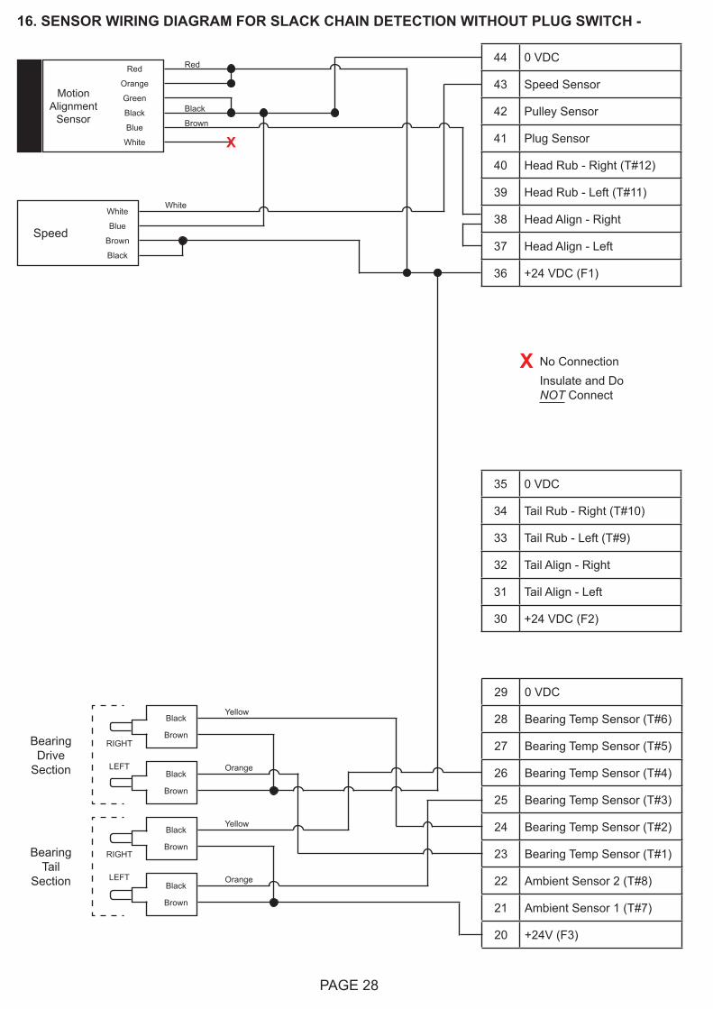
16. SENSOR WIRING DIAGRAM FOR SLACK CHAIN DETECTION WITHOUT PLUG SWITCH -
Green
Black
Blue
White
MotionAlignment
Sensor
Red
Orange
44 0 VDC
43 Speed Sensor
42 Pulley Sensor
41 Plug Sensor
40 Head Rub - Right (T#12)
39 Head Rub - Left (T#11)
38 Head Align - Right
37 Head Align - Left
36 +24 VDC (F1)
35 0 VDC
34 Tail Rub - Right (T#10)
33 Tail Rub - Left (T#9)
32 Tail Align - Right
31 Tail Align - Left
30 +24 VDC (F2)
Red
Black
Brown
X
29 0 VDC
28 Bearing Temp Sensor (T#6)
27 Bearing Temp Sensor (T#5)
26 Bearing Temp Sensor (T#4)
25 Bearing Temp Sensor (T#3)
24 Bearing Temp Sensor (T#2)
23 Bearing Temp Sensor (T#1)
22 Ambient Sensor 2 (T#8)
21 Ambient Sensor 1 (T#7)
20 +24V (F3)
Black
Brown
Black
Brown
Black
Brown
Black
Brown
Yellow
Orange
Yellow
Orange
Bearing Tail
Section
Bearing Drive
Section
RIGHT
LEFT
RIGHT
LEFT
White
Blue
Brown
Black
White
Speed
X No ConnectionInsulate and Do NOT Connect

PAGE 29
NOTES

PAGE 30
NOTES
PAGE 31
PRODUCT WARRANTY
1. EXCLUSIVE WRITTEN LIMITED WARRANTY
ALL PRODUCTS SOLD ARE WARRANTED BY THE COMPANY 4B COMPONENTS LIMITED AND 4B BRAIME COMPONENTS LIMITED HEREIN AFTER REFERRED TO AS 4B TO THE ORIGINAL PURCHASER AGAINST DEFECTS IN WORKMANSHIP OR MATERIALS UNDER NORMAL USE FOR ONE (1) YEAR AFTER DATE OF PURCHASE FROM 4B. ANY PRODUCT DETERMINED BY 4B AT ITS SOLE DISCRETION TO BE DEFECTIVE IN MATERIAL OR WORKMANSHIP AND RETURNED TO A 4B BRANCH OR AUTHORIZED SERVICE LOCATION, AS 4B DESIGNATES, SHIPPING COSTS PREPAID, WILL BE, AS THE EXCLUSIVE REMEDY, REPAIRED OR REPLACED AT 4B’S OPTION.
2. DISCLAIMER OF IMPLIED WARRANTY
NO WARRANTY OR AFFIRMATION OF FACT, EXPRESSED OR IMPLIED, OTHER THAN AS SET FORTH IN THE EXCLUSIVE WRITTEN LIMITED WARRANTY STATEMENT ABOVE IS MADE OR AUTHORIZED BY 4B. 4B SPECIFICALLY DISCLAIMS ANY LIABILITY FOR PRODUCT DEFECT CLAIMS THAT ARE DUE TO PRODUCT MISUSE, ABUSE OR MISAPPLICATIONS, AS AUTHORIZED BY LAW, 4B SPECIFICALLY DISCLAIMS ALL WARRANTIES THAT THE PRODUCT IS FIT OR MERCHANTABLE FOR A PARTICULAR PURPOSE.
3. NO WARRANTY “BY SAMPLE OR EXAMPLE”
ALTHOUGH 4B HAS USED REASONABLE EFFORTS TO ACCURATELY ILLUSTRATE AND DESCRIBE THE PRODUCTS IN ITS CATALOGS, LITERATURE, AND WEBSITES, SUCH ILLUSTRATIONS AND DESCRIPTIONS ARE FOR THE SOLE PURPOSE OF PRODUCT IDENTIFICATION AND DO NOT EXPRESS OR IMPLY A WARRANTY AFFIRMATION OF FACT, OF ANY KIND OR A WARRANTY OR AFFIRMATION OF FACT THAT THE PRODUCTS WILL CONFORM TO THEIR RESPECTIVE ILLUSTRATIONS OR DESCRIPTIONS. 4B EXPRESSLY DISCLAIMS ANY WARRANTY OR AFFIRMATION OF FACT, EXPRESSED OR IMPLIED, OTHER THAN AS SET FORTH IN THE EXCLUSIVE WRITTEN LIMITED WARRANTY STATEMENT ABOVE, INCLUDING, WITHOUT LIMITATION, THE IMPLIED WARRANTIES OF MERCHANTABILITY AND FITNESS FOR A PARTICULAR PURPOSE.
4. LIMITATION OF DAMAGES
ANY LIABILITY FOR CONSEQUENTIAL, INCIDENTAL, SPECIAL, EXEMPLARY, OR PUNITIVE DAMAGES, OR FOR LOSS OF PROFIT WHETHER DIRECT OR INDIRECT, IS EXPRESSLY DISCLAIMED.

Copyright © 2017 4B Group - All Rights Reserved
With subsidiaries in North America, Europe, Asia, Africa and Australia along with a worldwide network of distributors, 4B can provide practical solutions for all your applications no matter the location.
www.go4b.com REV051717
4B FRANCE9 Route de Corbie80800 Lamotte WarfuséeFranceTel: +33 (0) 3 22 42 32 26Fax: +33 (0) 3 22 42 37 33
4B AFRICA14 Newport Business Park Mica Drive, Kya Sand2163 JohannesburgSouth AfricaTel: +27 (0) 11 708 6114Fax: +27 (0) 11 708 1654
4B AUSTRALIAUnit 1/18 Overlord PlaceAcacia RidgeQueensland 4110AustraliaTel: +61 (0) 7 3711 2565Fax: +61 (0) 7 3711 2574
4B COMPONENTS LTD.625 Erie AvenueMorton, IL 61550USATel: 309-698-5611Fax: 309-698-5615
4B BRAIME COMPONENTS LTD.Hunslet RoadLeeds LS10 1JZUnited KingdomTel: +44 (0) 113 246 1800Fax: +44 (0) 113 243 5021
4B DEUTSCHLAND9 Route de CorbieLamotte WarfuséeF-80800FranceTel: +49 (0) 700 2242 4091Fax: +49 (0) 700 2242 3733
4B ASIA PACIFICBuild No. 899/1 Moo 20Soi Chongsiri, Bangplee-Tam Ru Road, Tanbon Bangpleeyai, Amphur Bangplee,Samutprakarn 10540ThailandTel: +66 (0) 2 173-4339Fax: +66 (0) 2 173-4338