WASTEWATER DIVISION WASTEWATER REUSE AND DRIP …€¦ · w062 11/12 netafim usa 5470 e. home ave....
68
WASTEWATER REUSE AND DRIP DISPERSAL DESIGN GUIDE WASTEWATER DIVISION
Transcript of WASTEWATER DIVISION WASTEWATER REUSE AND DRIP …€¦ · w062 11/12 netafim usa 5470 e. home ave....

W062 11/12
NETAFIM USA5470 E. HOME AVE.FRESNO, CA 93727CS 888.638.2346F 800.695.4753www.netafimusa.com
WASTEWATERREUSE ANDDRIP DISPERSALDESIGN GUIDE
WASTEWATER DIVISION

1
W A S T E W A T E R R E U S E A N D D R I P D I S P E R S A L G U I D E
TABLE OFCHARTS AND
ILLUSTRATIONS
Table of ContentsIntroduction..................................................... 3
Netafim.Bioline.Dripperline........................... 4
Why.Netafim.Only.Uses.Pressure.Compensating.Dripperline............................. 5
Basic.Assumptions........................................... 7
Wastewater.Flow.Determination................... 8
Site.Considerations........................................ 12
Soil.Considerations........................................ 14
Sample.Collection.......................................... 14
Determining.Soil.Texture.............................. 15
Restrictive.Layers........................................... 15
Native.vs..Disturbed.Soils.............................. 16
Soil.Hydraulic.Loading.Rate.......................... 17
System.Components...................................... 20
Zone.Requirements....................................... 24
Piping.Layout................................................. 24
Minimizing.Linear.Loading.by.Working.with.Topography...................... 25
Protecting.the.Piping.Network.................... 25
Drainback.Considerations............................. 28
Dosing.and.Controls...................................... 29
Recommended.Drip.Dispersal.Operation.Controls....................................... 30
Sequence.of.Operation................................. 30
How.to.Dose.................................................. 31
Dose.and.Flush.Volumes............................... 32
Filters.and.Filter.Cleaning............................. 34
Field.Flush...................................................... 36
Root.Intrusion................................................ 36
Installation..................................................... 37
Operation.and.Maintenance........................ 40
Typical.Layouts.............................................. 41
Freezing.Climate.Design.and.Other.Considerations............................. 46
Netafim.Product.Warranty........................... 49
TablesTable No.1.. Maximum.Length.of.Bioline.Laterals.... 5
2.. Non-Pressure.Compensating.Dripper.Flow.Rate.vs..Pressure............................. 6
3.. Bioline.Dripper.Flow.Rate.vs..Pressure.............................................. 6
4.. Average.Daily.Residential.Wastewater.Flows................................... 8
5.. Residential.Water.Use.by.Fixture.or.Appliance............................... 9
6.. Commercial.Water.Use.by.Fixture.or.Appliance............................. 10
7.. Institutional.Water.Use.Typical.Flow.Rates................................. 11
8.. Recreational.Water.Use.Typical.Flow.Rates................................. 12
9.. Slope.Conversion.................................. 14
10.. Sample.Soil.Loading.Rates................... 18
11.. Maximum.Length.of.Bioline.Laterals...................................... 27
12.. Recommended.Dosing.Tank.Size.Based.on.Bedrooms....................... 31
13.. Holding.Volumes.in.Gallons.for.Pipe..................................... 32
14.. Warranty.Information.......................... 50

W A S T E W A T E R R E U S E A N D D R I P D I S P E R S A L G U I D E
2
W A S T E W A T E R R E U S E A N D D R I P D I S P E R S A L G U I D E
TablesMetric.Conversion.Factors............................ 51
Friction.Loss.Charts.
Sch.40.PVC.................................................. 52
Sch.80.PVC.................................................. 53
CL.315.PVC................................................. 54
CL.200.PVC................................................. 55
CL.160.PVC................................................. 56
CL.125.PVC................................................. 57
PE.Pipe........................................................ 58
Sch.40.Standard.Steel................................ 59
Type.K.Copper............................................ 60
Round.Tank.Capacity.................................... 61
Rectangular.Tank.Capacity........................... 61
Conversion.Charts......................................... 62
Friction.Loss.Through.Fittings...................... 63
Thermal.Expansion........................................ 63
Contents.of.a.Pipe......................................... 63
Conversion.Formulas.and.Factors................. 64
Pressure.Loss.Through.Water.Meters........... 65
Temperature.Conversion.............................. 66
IllustrationsFigure No.1.. The.Bioline.Dripper.................................. 4
2.. The.Precision.of.the.Bioline.Dripperline................................... 5
3.. Typical.Treatment.System.&.Drip.Dispersal.System.Layout............... 7
4.. Soil.Texture.Triangle............................... 15
5.. “Soup.Bowl.Effect“................................ 16
6.. Sample.Hydraulic.Loading.Rates.Based.on.Soil.Texture.Triangle......................... 17
7.. Typical.Air/Vacuum.Relief.Valve.Detail.................................. 21
8.. Loop.and.Flexible.Connections.............. 22
9.. Start.Connection.with.Flex.Pipe.on.Flat.Field.Layout................................ 23
10.. End.Start.Connection.with.Flex.Pipe.on.Flat.Field.Layout................................ 23
11.. Less.Desirable.Slope.Layout................... 25.
12.. More.Desirable.Slope.Layout................. 25
13.. Screen.Filter.with.Debris.Passing.Through..................................... 34
14.. Disc.Filter.Ring........................................ 35
15.. The.MB-40.Multi-Blade.Vibratory.Plow........................................ 38
16.. MB-40.Minimizes.Damage.to.Existing.Landscape............................. 38
17.. MB-40.Does.Not.Disturb.the.Grade....... 38
18.. MB-40.Can.be.Mounted.on.the.Vermeer.RTX-450.................................... 38
19.. “Drip.and.Fill”.Technique...................... 39
20.. Mechanized.Equipment......................... 39
System Layouts
. Opposing.Manifold.Layout.................... 42
. Single.Trench.Layout.............................. 43
. Irregular.Field.Shape.Layout.................. 44
. Multiple.Zone.Layout............................. 45

W A S T E W A T E R R E U S E A N D D R I P D I S P E R S A L G U I D E
3
W A S T E W A T E R R E U S E A N D D R I P D I S P E R S A L G U I D E
This.guide.covers.the.basics.of.design.for.Netafim.Bioline®.drip.dispersal.applications..While.secondary.treated.effluent.will.normally.be.used,.many.of.the.same.design.concepts.for.septic.tank.effluent.may.apply.
Because.onsite.wastewater.designs.are.subject.to.state.and.local.regulations,.any.regulatory.specification.must.be.given.precedence.over.the.recommendations.included.here..If.local.regulations.allow.design.parameters.which.are.more.liberal.than.those.expressed.in.this.guide,.the.designer.should.bear.in.mind.that.the.conservative.recommendations.herein.are.based.on.actual.design.experience.and.analysis.of.both.properly.functioning.and.failed.onsite.systems..When.it.comes.to.design,.Netafim.takes.a.conservative.approach.
This guide is not meant to replace the services of a design professional. Netafim recommends that a licensed professional be consulted for proper onsite system design and operation.
Overview
Drip.technology.was.originally.developed.for.the.agricultural.industry.to.improve.the.efficient.delivery.of.water.to.plants,.especially.in.environments.where.water.supply.is.limited..The.technique.involved.delivering.water.that.plants.actually.use.directly.into.the.root.zone.and.relying.on.horizontal.and.vertical.movement.through.the.soil.to.disperse.the.water.evenly..Netafim.is.the.world.leader.in.drip.applications.and.its.drippers,.filters,.valves.and.other.products.have.become.industry.standards.around.the.world.
Subsurface.drip.dispersal.is.the.most.efficient.method.of.dispersing.wastewater.effluent.into.the.soil.and.presents.the.designer.with.a.superior.solution.for.virtually.every.soil.type.
The.Netafim.drip.dispersal.solution.delivers.effluent.into.the.shallow.subsurface.and.biologically-active.root.zone.of.plants,.allowing.plant.uptake.for.nutrient.removal,.and.slow.effluent.dispersal.into.the.soil.medium.for.further.treatment.
The.U.S..Environmental.Protection.Agency.(EPA).has.recognized.that.onsite.treatment.of.domestic.wastewater.is.a.permanent.rather.than.temporary.solution.for.wastewater.treatment.when.centralized.collection.systems.are.not.feasible..Increasing.public.concern.about.issues.related.to.the.effective.and.reliable.treatment.and.dispersal.of.onsite.wastewater.has.created.a.climate.for.change.beyond.conventional.septic.tanks.and.drainfields..The.onsite.industry.has.responded.with.improved.technology.for.wastewater.treatment.and.regulations.have.become.more.explicit.and.scientifically.based..These.are.key.reasons.why.interest.in.drip.dispersal.in.the.onsite.industry.has.increased.so.rapidly.
As.demand.increases.for.residential.development.in.formerly.rural.areas.and.in.less-than-optimal.site.conditions.for.older-style.onsite.wastewater.dispersal,.the.importance.of.alternative.technologies.increases..Advanced.onsite.wastewater.treatment.combined.with.drip.dispersal.is.the.best.strategy.for.effectively.treating.and.dispersing.the.treated.wastewater.
Subsurface.drip.dispersal.has.a.number.of.benefits:
•. Very.even.effluent.distribution.over.large.areas,.including.slopes
•. Can.be.applied.in.almost.any.climate.or.soil.conditions,.as.well.as.high.wind.areas,.odd.shaped.areas,.close.to.buildings.and.high.water.table.environments
•. Reduced.localized.loading.rates
•. Potential.of.animal.and.human.contact.is.much.lower.than.other.dispersal.techniques
•. Installation.does.not.require.major.disruption.to.the.drain.field.area,.taking.advantage.of.natural.or.modified.landscape.plans
•. Provides.for.extended.contact.time.with.soil
•. Effluent.can.often.be.re-used.for.irrigation.of.lawns,.shrubs,.and.trees.-.nitrate.and.phosphorus.uptake.by.plants.is.a.further.benefit
INTRODUCTION

W A S T E W A T E R R E U S E A N D D R I P D I S P E R S A L G U I D E
4
W A S T E W A T E R R E U S E A N D D R I P D I S P E R S A L G U I D E
•. Beneficial.wastewater.nutrients.are.available.for.plant.uptake.and.evapotranspiration.is.maximized
•. Special.consideration.potential.for.use.in.a."green.building".applications.-.the.onsite.treatment.of.the.wastewater.ensures.no.infrastructure.strain.on.municipal.treatment.and.the.beneficial.reuse.of.the.effluent.could.include.irrigation.
This.guide.focuses.on.Netafim.Bioline®.dripperline1.as.the.drip.dispersal.product..Bioline.is.a.state-of-the-art.drip.dispersal.tubing.that.is.manufactured.specifically.for.wastewater.applications..While.Netafim.manufactures.hundreds.of.types.of.dripperline,.including.non-pressure.compensating.dripperline,.the.features.and.proven.performance.of.Bioline.make.any.reliance.on.non-pressure.compensating.dripperlines.unnecessary..Chief.among.the.reasons.that.Netafim.Bioline.pressure.compensating.dripperline.is.the.chosen.standard.include:
•. Broadest.pressure.compensation.range.of.any.dripperline:.7.-.58.psi
•. Broadest.range.of.dripper.flow.rates.to.choose.from:.0.4,.0.6.or.0.9.GPH
•. Dripper.spacings.of.12",.18".or.24".(custom.spacings.available)
•. Bioline’s.continuous.self-flushing.design.ensures.drippers.purge.debris.any.time.they.are.operating,.not.just.at.the.beginning.or.end.of.a.cycle
•. Built-in.physical.root.barrier.protects.against.root.intrusion.without.the.need.for.chemical.protection
•. Large.internal.flow.paths.inside.the.dripper.mean.Bioline.only.requires.120.mesh/130.micron.filtration
•. Pressure.compensating.dripper.design.ensures.even.application.of.effluent.across.a.broad.area
•. Dripperline.lateral.lengths.are.the.longest.in.the.industry
•. No.special.storage.or.handling.requirements.ensure.that.outdoor.storage.is.acceptable
NETAFIMBIOLINE®
DRIPPERLINE
Figure 1 - The Bioline Dripper. Capturing the effluent from the center of the flow is critical to effective dripper operation. This shows how the dripper is positioned in the center of the flow and is less likely to suffer contamination like drippers that capture water from the wall of the pipe where it is dirtiest.
CleanestEffluent
FlowDebris
DripperInlet Filter
BiolineDripper
1 Atvarioustimesthefollowingwordswillbeusedinterchangeably:Bioline,driptubing,dripline,dripperline,dripdispersaltubing.

5
W A S T E W A T E R R E U S E A N D D R I P D I S P E R S A L G U I D E
The fast answer about only using pressure compensating dripperline is:
• Predictable
• Forgiving
• Easy to design with
• Provides a continuous self-flushing feature
• Provides a very consistent flow over time
Table 1 - This chart shows the maximum lengths of laterals when using Netafim Bioline. The footage represents how far the dripperline can reach and how each dripper delivers equal flow under pressure compensating conditions. (These distances will decrease when designing for the appropriate flushing velocity and should not be used for design purposes. See page 29 for more information on lateral length data when using various flushing velocities).
WHY NETAFIM ONLY USES PRESSURE
COMPENSATING DRIPPERLINE
Figure 2 – The Precision of Bioline Pressure Compensating Dripperline. Across this broad area are thousands of feet of dripperline delivering equal discharge rates from each dripper. Non-pressure compensating dripperlines cannot equal this degree of precision.
Dripper Spacing
Dripper Flow Rate (GPH)
BIOLINE DOSING CHART Maximum Length (feet) of a Single Lateral
12”
Inle
t Pre
ssur
e(p
si)
18” 24”
Lateral lengths are calculated for operation while dosing, and allow for the pressure at the end of the dripperline to be 7 psi or greater. Their data does not take scouring velocity into account.
15
25
35
45
0.4
292
397
460
505
0.6
233
312
365
407
0.9
175
238
260
295
0.4
410
558
656
732
0.6
322
438
514
574
0.9
247
335
394
429
0.4
510
660
760
880
0.6
405
550
649
725
0.9
308
423
497
555

W A S T E W A T E R R E U S E A N D D R I P D I S P E R S A L G U I D E
6
W A S T E W A T E R R E U S E A N D D R I P D I S P E R S A L G U I D E
Pressure.compensating.(PC).dripperlines.have.been.used.in.a.variety.of.subsurface.applications.for.decades..Whether.the.application.is.agriculture,.where.crop.quality.is.largely.dependant.on.each.plant.getting.equal.water,.or.landscape,.where.even.watering.yields.well-balanced.plantings.and.turf,.pressure.compensating.dripperlines.excel.
Beyond.the.design.and.maintenance.ease.that.PC.dripperline.offers.due.to.its.precise.and.measurable.rate.flow,.there.is.more..Bioline's.ability.to.purge.debris.whenever.it.gets.into.the.dripper.is.another.reason.Netafim.does.not.use.non-pressure.compensating.dripperlines.for.wastewater..Using.a.dripper.that.may.only.clean.itself.at.the.beginning.or.end.of.a.dose.can.lead.to.drippers.not.operating.properly..This.does.not.happen.with.Bioline.
Certain.soils.have.the.ability.to.reduce.or.actually.cut-off.the.flow.of.non-PC.drippers..Especially.in.tight.soils,.pressure.created.in.the.soil.by.the.water.can.increase.to.the.point.where.a.non-pressure.compensating.dripper.can.actually.close.and.stop.dripping..Though.these.pressures.dissipate.by.gravity.after.dosing.-.eliminating.it.during.dosing.is.the.object..Even.on.flat.terrain,.using.non-PC.dripperline.can.significantly.and.negatively.affect.the.quality.of.the.dose.
Table 2 - The curved flow rate of a typical non-pressure compensating dripperline highlights why it is a poor choice for effluent dispersal. As the lateral length increases and/or the pressure decreases, the flow decreases as well. This makes designing a system difficult and reduces the effective management of effluent dispersal over the drip field.
Table 3 - The flat flow rate line of Bioline represents the concept of
pressure compensation and the resulting even discharge of water
from each emitter along the full length of the dripperline lateral. This
makes system design much easier and increases the effectiveness of effluent dispersal in the drip
field, even if there are elevation differences.
TYPICAL NON-PRESSURE COMPENSATINGDRIPPER FLOW RATE vs PRESSURE
Pressure (psi)
Flow
Rat
e (G
PH)
1.0
0.9
0.8
0.7
0.6
0.5
0.4
0.3
0.2
0.1
0 10 20 30 40 50
BIOLINE® Dripper Flow Rate vs. Pressure
0.9 GPH
0.6 GPH
0.4 GPH
1.0
0.9
0.8
0.7
0.6
0.5
0.4
0.3
0.2
0.1
0 10 20 30 40 50 58
Pressure (psi)Between 0 and 7 psi, the dripper functions as a turbulent flow emitter,
ensuring that the nominal design flow is not exceeded at system start-up.
Flow
Rat
e (G
PH)

W A S T E W A T E R R E U S E A N D D R I P D I S P E R S A L G U I D E
7
W A S T E W A T E R R E U S E A N D D R I P D I S P E R S A L G U I D E
Figure 3 - Typical Treatment System & Drip Dispersal System Layout. Illustration provided by Texas Cooperative Extension.
This.guide.assumes.the.following.wastewater.conditions:
•.Secondary-treated,.domestic.strength.effluent,.though.residential-strength.septic.tank.effluent.can.be.used.with.proper.design,.filtration.and.operation
•.30/30.(ppm).BOD/TSS
•.Fats,.oils,.and.grease.(FOG).less.than.20.ppm
This.quality.of.effluent.can.be.produced.by.any.number.of.advanced.onsite.treatment.technologies..While.there.are.many.successful.drip.dispersal.systems.on.septic.tank.quality.effluent.wastewater,.special.care.must.be.taken.in.the.system.design.
Effluent.typically.leaves.the.treatment.system.and.enters.into.an.adequately-designed.storage.(dosing).tank..These.tanks.allow.for.both.a.working.level.and.reserve.capacity.above.the.high.water.level.alarm..The.drip.dispersal.system.is.designed.to.distribute.the.wastewater.uniformly.over.the.drip.field.throughout.a.24-hour.day.or.as.local.regulations.dictate.
The.control.system.regulates.the.flow.and.may.also.provide.for.filter.and.field.flushing,.zone.selection.and.alarms.whenever.operational.conditions.are.exceeded.
Since.Bioline®.requires.pressure.to.function,.pumps.will.normally.be.used.to.deliver.the.proper.flow.and.pressure.to.the.dripline.laterals..System.pressure.is.also.required.to.operate.filters.(automatic.or.manual.backflush),.which.remove.suspended.organic.and.inorganic.particles.
Multiple.zones.of.dripperline.may.be.necessary.or.desired.to.keep.pump.size.small.and/or.to.meet.local.regulations,.but.pump.capacity.should.allow.for.adequate.flushing.of.the.dripperline.and.piping.network.components.during.manual.or.automatic.field.flush.cycles..Design.considerations.derived.from.these.principles.are.detailed.in.this.design.guide.
Drip.tubing.is.frequently.installed.at.a.depth.of.6”,.but.8”.to.12”.depths.may.be.recommended.to.minimize.potential.human.or.animal.contact.and.to.ensure.proper.effluent.dispersal.into.the.biologically-active.soil.layer..Cold.climates.may.require.even.deeper.burial,.or.additional.cover.based.on.local.conditions..Installing.dripperline.below.the.soil’s.freeze.depth.is.generally.safe,.but.there.are.numerous.installations.at.relatively.shallow.depths.in.cold.climates.with.appropriate.design.and.routine.dosing..See.the.section.titled."Freezing.Climate.Design.and.Other.Considerations".on.page.48.
BASIC ASSUMPTIONS
Wastewater Treatment
System
Filtration
Supply
Vacuum Breaker
Pump Tank
W A S T E W A T E R R E U S E A N D D R I P D I S P E R S A L G U I D E
8
W A S T E W A T E R R E U S E A N D D R I P D I S P E R S A L G U I D E
WASTEWATER FLOW
DETERMINATION
Most.critical.to.a.proper.design.is.matching.the.soil’s.capacity.to.absorb.water.with.the.dripperline’s.application.rates.and.the.demand.for.dispersal.of.the.design.flow..In.this.regard,.the.designer.must.take.into.account:
•.Water.flow.over,.into,.and.through.the.soil
•.Soil.morphology.(structure,.texture)
•.Storage.of.water.in.the.soil.column
•.The.loss.of.water.to.the.air.through.evaporation
•.Exchange.to.the.air.through.plant.transpiration
This.design.guide.shows.how.accurate.information.about.daily.wastewater.flow,.proper.soil.analysis.and.thorough.site.evaluation.will.result.in.a.successful.and.cost.effective.drip.dispersal.system.
Note:.Netafim.has.developed.an.easy-to-use.computer.program.to.do.many.of.the.quantitative.design.analysis.steps.based.on.gallons.available.per.day,.soil.loading.rates,.pump.size,.number.of.doses,.etc..It.is.available.on.the.Netafim.Wastewater.Division.CD.and.on.our.website.at.www.netafim-usa-wastewater.com..The.following.discussions.provide.the.context.for.these.calculations.
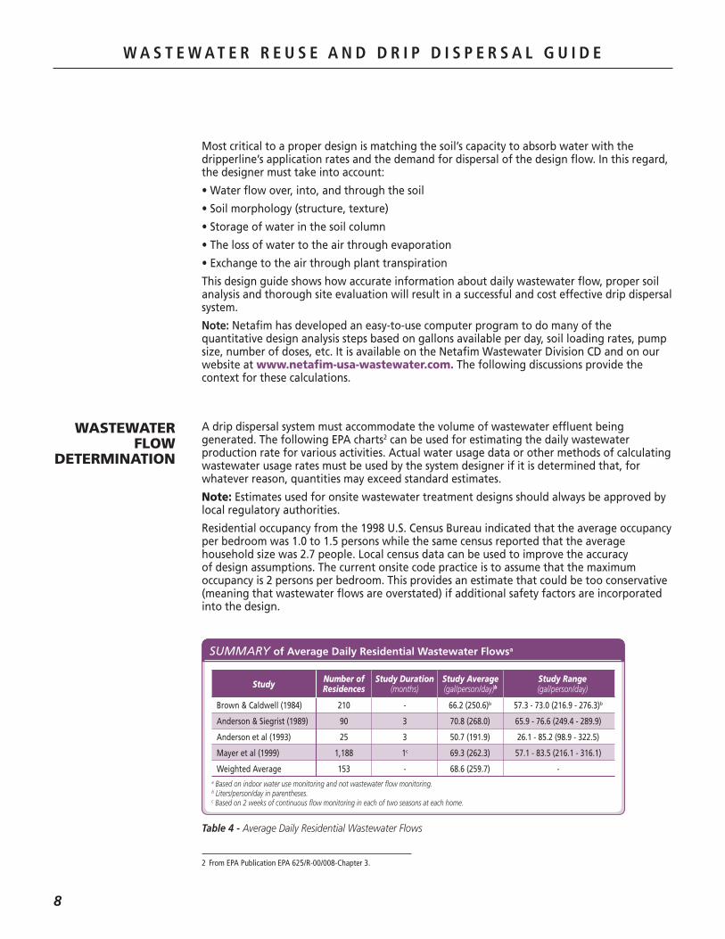
A.drip.dispersal.system.must.accommodate.the.volume.of.wastewater.effluent.being.generated..The.following.EPA.charts2.can.be.used.for.estimating.the.daily.wastewater.production.rate.for.various.activities..Actual.water.usage.data.or.other.methods.of.calculating.wastewater.usage.rates.must.be.used.by.the.system.designer.if.it.is.determined.that,.for.whatever.reason,.quantities.may.exceed.standard.estimates..
Note:.Estimates.used.for.onsite.wastewater.treatment.designs.should.always.be.approved.by.local.regulatory.authorities.
Residential.occupancy.from.the.1998.U.S..Census.Bureau.indicated.that.the.average.occupancy.per.bedroom.was.1.0.to.1.5.persons.while.the.same.census.reported.that.the.average.household.size.was.2.7.people..Local.census.data.can.be.used.to.improve.the.accuracy.of.design.assumptions..The.current.onsite.code.practice.is.to.assume.that.the.maximum.occupancy.is.2.persons.per.bedroom..This.provides.an.estimate.that.could.be.too.conservative.(meaning.that.wastewater.flows.are.overstated).if.additional.safety.factors.are.incorporated.into.the.design.
Table 4 - Average Daily Residential Wastewater Flows
SUMMARY of Average Daily Residential Wastewater Flowsa
a Based on indoor water use monitoring and not wastewater flow monitoring.b Liters/person/day in parentheses.c Based on 2 weeks of continuous flow monitoring in each of two seasons at each home.
Brown & Caldwell (1984) 210 - 66.2 (250.6)b 57.3 - 73.0 (216.9 - 276.3)b
Anderson & Siegrist (1989) 90 3 70.8 (268.0) 65.9 - 76.6 (249.4 - 289.9)
Anderson et al (1993) 25 3 50.7 (191.9) 26.1 - 85.2 (98.9 - 322.5)
Mayer et al (1999) 1,188 1c 69.3 (262.3) 57.1 - 83.5 (216.1 - 316.1)
Weighted Average 153 - 68.6 (259.7) -
Study Number ofResidences
Study Duration(months)
Study Average(gal/person/day)b
Study Range(gal/person/day)
2 FromEPAPublicationEPA625/R-00/008-Chapter3.

W A S T E W A T E R R E U S E A N D D R I P D I S P E R S A L G U I D E
9
W A S T E W A T E R R E U S E A N D D R I P D I S P E R S A L G U I D E
Based.on.the.data.in.Table.4,.estimated.average.daily.wastewater.flows.of.approximately.50.-.70.gallons.per.person.per.day.(189.to.265.liters.per.person.per.day).would.be.typical.for.residential.dwellings.built.before.1994.
RESIDENTIAL WATER USE by Fixture or Appliancea, b
Fixture/Use Gallons/Use(average range)
Uses/Person/Day(average range)
Gallons/Person/Day(average range)c
Percent Total(average range)
Toilet 3.5 (2.9 - 3.9) 5.05 (4.5 - 5.6) 18.5 (15.7 - 22.9) 26.7 (22.6 - 30.6)
Shower 17.2d (14.9 - 18.6) 0.75d (0.6 - 0.9) 11.6 (8.3 - 15.1) 16.8 (11.8 - 20.2)
Bath See Shower See Shower 1.2 (0.5 - 1.9) 1.7 (0.9 - 2.7)
Clothes Washer 40.5 0.37 (0.30 - 0.42) 15.0 (12.0 - 17.1) 21.7 (17.8 - 28.0)
Dishwasher 10.0 (9.3 - 10.6) 0.10 (0.06 - 0.13) 1.0 (0.6 - 1.4) 1.4 (0.9 - 2.2)
Faucets 1.4e 8.1f (6.7 - 9.4) 10.9 (8.7 - 12.3) 15.7 (12.4 - 18.5)
Leaks n/a n/a 9.5 (3.4 - 17.6) 13.7 (5.3 - 21.6)
Other Domestic n/a n/a 1.6 (0.0 - 6.0) 2.3 (0.0 - 8.5)
Total n/a n/a 69.3 (57.1 - 83.5) 100a Results from AWWARF REUWS at 1,188 homes in 12 metropolitan areas. Homes surveyed were served by public water supplies, which operate at higher pressure than private water sources. Leakage rates might be lower for homes on private water supplies.
b Results are averages over range. Range is the lowest to highest average for 12 metropolitan areas.c Gal/person/day might not equal gal/use multiplied by uses/person/day because of differences in the number of data points used to calculate means.
d Includes shower and bath.e Gallons per minute.f Minutes of use per person per day. Source: Mayer et al., 1999
Table 5 - Typical Flow Rates from Residential Sources

W A S T E W A T E R R E U S E A N D D R I P D I S P E R S A L G U I D E
10
W A S T E W A T E R R E U S E A N D D R I P D I S P E R S A L G U I D E
Table 6 - Typical Flow Rates from Commercial Sources
COMMERCIAL WATER USE by Fixture or Appliancea, b
Facility UnitRange Typical
Flow/Gallons/Unit/Day
Airport Passenger 2 - 4 3 8 - 15 11
Apartment House Person 40 - 80 50 150 - 300 190
Automobile Service StationC Vehicle Served 8 - 15 12 30 - 57 45
Automobile Service StationC Employees 9 - 15 13 34 - 57 45
Bar Customer 1 - 5 3 4 - 19 11
Bar Employees 10 - 16 13 38 - 61 49
Boarding House Person 25 - 60 40 95 - 230 150
Department Store Toilet Room 400 - 600 500 1,500 - 2,300 1,900
Department Store Employee 8 - 15 10 30 - 57 38
Hotel Guest 40 - 60 50 150 - 230 190
Hotel Employee 8 - 13 10 30 - 49 38
Industrial Building (sanitary waste only) Employee 7 - 16 13 26 - 61 49
Laundry (self-service) Machine 450 - 650 550 1,700 - 2,500 2,100
Laundry (self-service) Wash 45 - 55 50 170 - 210 190
Office Employee 7 - 16 13 26 - 61 49
Public Lavatory User 3 - 6 5 11 - 23 19
Restaurant (with toilet) Meal 2 - 4 3 8 - 15 11
Restaurant (conventional) Customer 8 - 10 9 30 - 38 34
Restaurant (short order) Customer 3 - 8 6 11 - 30 23
Restaurant (bar/cocktail lounge) Customer 2 - 4 3 8 - 15 11
Shopping Center Employee 7 - 13 10 26 - 49 38
Shopping Center Parking Space 1 - 3 2 4 - 11 8
Theater Seat 2 - 4 3 8 - 15 11
Range Typical
Flow/Liters/Unit/Day
a Some systems serving more than 20 people might be regulated under US EPA’s Class V Underground Injection Control (UIC) Program. See http://www.epa.gov/safewater/uic.html for more information.
b These data incorporate the effect of fixtures complying with the U.S. Energy Policy Act (EPACT) of 1994.c Disposal of automotive wastes via subsurface wastewater infiltration systems is banned by Class V UIC regulations to protect ground water. See http://www.epa.gov/safewater/uic.html for more information.
Source: Crites and Tchobanoglous, 1998.

W A S T E W A T E R R E U S E A N D D R I P D I S P E R S A L G U I D E
11
W A S T E W A T E R R E U S E A N D D R I P D I S P E R S A L G U I D E
Table 7 - Typical Flow Rates from Institutional Sources
INSTITUTIONAL WATER USE Typical Flow Ratesa
Facility UnitRange Typical
Flow/Gallons/Unit/Day
Assembly Hall Seat 2 - 4 3 8 - 15 11
Hospital, Medical Bed 125 - 240 165 470 - 910 630
Hospital, Medical Employee 5 - 15 10 19 - 57 38
Hospital, Mental Bed 75 - 140 100 280 - 530 380
Hospital, Mental Employee 5 - 15 10 19 - 57 38
Prison Inmate 80 - 150 120 300 - 570 450
Prison Employee 5 - 15 10 19 - 57 38
Rest Home Resident 50 - 120 90 190 - 450 340
Rest Home Employee 5 - 15 10 19 - 57 38
School (day w/cafeteria, gym, showers) Student 15 - 30 25 57 - 110 95
School (day w/cafeteria) Student 15 - 30 15 38 - 76 57
School (day w/o cafeteria, gym, showers) Student 10 - 20 11 19 - 64 42
School (boarding) Student 50 - 100 75 190 - 380 280
Range Typical
Flow/Liters/Unit/Day
a Systems serving more than 20 people might be regulated under US EPA’s Class V UIC Program. See http://www.epa.gov/safewater/uic.html for more information.
Source: Crites and Tchobanoglous, 1998.

W A S T E W A T E R R E U S E A N D D R I P D I S P E R S A L G U I D E
12
W A S T E W A T E R R E U S E A N D D R I P D I S P E R S A L G U I D E
RECREATIONAL WATER USE Typical Flow Ratesa
Facility UnitRange Typical
Flow/Gallons/Unit/Day
Apartment, Resort Person 50 - 70 60 190 - 280 230
Bowling Alley Alley 150 - 250 200 270 - 950 780
Cabin, Resort Person 8 - 50 40 80 - 190 150
Cafeteria Customer 1 - 3 2 4 - 11 8
Cafeteria Employee 8 - 12 10 30 - 45 38
Camp (pioneer type) Person 15 - 30 25 57 - 110 95
Camp (children’s w/toilet, bath) Person 35 - 50 45 130 - 190 170
Camp (day w/meals) Person 10 - 20 15 38 - 76 57
Camp (day w/o meals) Person 10 - 15 13 38 - 57 49
Camp (luxury, private bath) Person 75 - 100 90 280 - 380 340
Camp (trailer camp) Trailer 75 - 150 125 280 - 570 470
Campground (developed) Person 20 - 40 30 76 - 150 110
Cocktail Lounge Customer 12 - 25 20 45 - 95 76
Coffee Shop Customer 4 - 8 6 15 - 30 23
Coffee Shop Employee 8 - 12 10 30 - 45 38
Country Club Guest 60 - 130 100 230 - 490 380
Country Club Onsite Employee 10 - 15 13 38 - 57 49
Dining Hall Meal Served 4 - 10 7 15 - 38 28
Dormatory, Bunkhouse Person 20 - 50 40 76 - 190 150
Fairground Visitor 1 - 2 2 4 - 8 8
Hotel, Resort Person 40 - 60 50 150 - 230 190
Picnic Park (flush toilets) Visitor 5 - 10 8 19 - 38 30
Store, Resort Customer 1 - 4 3 4 - 15 11
Store, Resort Employee 8 - 12 10 30 - 45 38
Swimming Pool Customer 5 - 12 10 19 - 45 38
Swimming Pool Employee 8 - 12 10 30 - 45 38
Theater Seat 2 - 4 3 8 - 15 11
Visitor Center Visitor 4 - 8 5 15 - 30 19
Range Typical
Flow/Liters/Unit/Day
aSome systems serving more than 20 people might be regulated under US EPA’s Class V UIC Program.
Source: Crites and Tchobanoglous, 1998.
Table 8 - Typical Flow Rates From Recreational Facilities
Before.doing.any.detailed.design.specification,.it.is.necessary.to.evaluate.specific.site.features.
This.assessment.should.include.the.following:
Site Boundaries:.Most.state.and.local.regulations.will.establish.how.close.dripperlines.may.be.placed.to.property.lines,.home.foundations.and.other.permanent.property.features.
Special Features:.Community.water.distribution.lines,.property.and.utility.easements,.wells,.treatment.systems,.water.lines.from.wells,.etc.,.require.setbacks;.50.to.100.feet.is.typical..Surface.waters,.including.ditches,.ponds,.lakes,.streams.and.even.intermittent.water.courses.also.require.specific.setbacks..Follow.all.local.regulations.
SITE CONSIDERATIONS

W A S T E W A T E R R E U S E A N D D R I P D I S P E R S A L G U I D E
13
W A S T E W A T E R R E U S E A N D D R I P D I S P E R S A L G U I D E
Examples:
1.. If.the.difference.in.elevation.is.1.foot.over.a.horizontal.distance.of.100.feet,.slope.gradient... . is.1%..
2.. A.slope.that.drops.10.vertical.feet.in.100.horizontal.feet.is.a.10%.slope.(vertical.drop/.. . horizontal.distance.times.100).
3.. A.slope.of.45°.is.a.slope.of.100.percent,.because.the.difference.in.elevation.between.two... . points.100.meters.apart.horizontally.is.100.meters.on.a.45°.slope..
Note:.The.higher.the.percent,.the.steeper.the.slope!
The.elevation.of.a.slope.is.important.because.it.determines.the.rate.at.which.water.(and.effluent).flows.downhill..Water.flows.slowly.over.a.gentle.slope.and.rapidly.over.a.steep.one..The.steepness.of.a.slope.has.been.evaluated.by.the.United.States.Department.of.Agriculture’s.Soil.Conservation.Service.as.follows:.
•.. Nearly.level.(0.-.2%)..Has.no.limitation.on.its.uses..Any.limitations.are.the.result.of.other... . factors,.such.as.drainage..
•.. Gently.Sloping.(3%.-.6%)..Desirable.for.almost.any.type.of.development;.may.have.erosion... . problems;.limitations.are.due.mostly.to.factors.other.than.slope..
•.. Moderately.Sloping.(6%.-.12%)..May.have.severe.erosion.problems.and.has.a.strong... . appeal.for.single-family.development..
•.. Strongly.Sloping.(12%.-.18%)..Has.severe.limitations.for.all.types.of.construction.... . Residential.development.is.sometimes.considered.because.of.the.scenic.views.associated... . with.such.terrain,.or.when.other.sites.are.unavailable..
•.. Steep.Slopes.(18%.and.over)..Undesirable.for.most.development..
Prior Land Use:.Research.should.be.conducted.to.identify.any.prior.activities.on.the.proposed.site.that.may.have.affected.soil.characteristics..These.effects.could.include.compaction,.foreign.soils,.buried.materials,.etc.
Future Land Use Restrictions:.The.drip.dispersal.field.can.be.installed.under.a.permanent.lawn,.among.trees.or.other.landscape.features,.provided.that.proper.set.backs.are.followed..Any.future.permanent.structures.that.will.affect.soil.texture.and.water.flow.through.the.soil.must.be.avoided.over.a.drip.dispersal.field,.including.but.not.limited.to.the.following:.out-buildings,.parking.areas,.swimming.pools,.tennis.courts,.home.additions,.decks,.etc..The.designer.should.consult.with.the.property.owner.regarding.anticipated.improvements.to.the.property.and.avoid.these.areas.
Precipitation and Landscape Position:.If.the.site.is.in.an.area.that.experiences.seasonal,.intense,.or.even.short.duration.precipitation.events.consider.regrading.the.area.to.encourage.direct.runoff.
Slope:.Slope.or.slope.gradient.is.the.inclination.of.the.surface.of.the.soil.from.horizontal.and.is.expressed.as.a.percentage.of.the.distance.between.those.points..

W A S T E W A T E R R E U S E A N D D R I P D I S P E R S A L G U I D E
14
W A S T E W A T E R R E U S E A N D D R I P D I S P E R S A L G U I D E
The.Slope.Conversion.chart.shows.equivalences.between.percentage.of.gradient.and.angle.of.slope.in.degrees..
Drip.dispersal.encourages.lateral.(horizontal),.not.just.vertical.movement.throughout.the.soil..This.makes.it.an.excellent.choice.for.both.level.surfaces.and.slopes..This.is.especially.true.with.the.use.of.pressure.compensating.emitters.and.proper.zoning..Additional.considerations.about.slopes.include.whether:
•. There.is.a.natural.or.artificial.barrier.down-slope.from.the.proposed.site.that.could.provide.opportunities.for.water.to.surface.(such.as.hillside.cuts.or.walls)
•. The.drip.tubing.can.be.laid.out.along.the.contour.of.the.slope
•. System.geometry.can.be.used.that.minimizes.linear.loading.rate
•. The.design.can.incorporate.air.release.valves,.check.valves,.zones.and.other.means.to.equalize.flow.and.to.prevent.drainback.(See.the.design.and.layout.discussions.that.follow.)
Table 9 - Slope Conversion Chart
SLOPE Conversion
Percent Angle
0 0˚ 00’ 0˚ 0
5 2˚ 52’ 2˚ 3.5
10 5˚ 43’ 4˚ 7.0
15 8˚ 32’ 6˚ 10.5
20 11˚ 19’ 8˚ 14.0
25 14˚ 02’ 10˚ 17.6
30 16˚ 42’ 12˚ 21.2
35 19˚ 17’ 15˚ 26.8
40 21˚ 48’ 20˚ 36.4
50 26˚ 34’ 25˚ 46.6
60 30˚ 58’ 30˚ 57.7
70 34˚ 59’ 35˚ 70.0
80 38˚ 39’ 40˚ 83.9
90 41˚ 59’ 45˚ 100.0
100 45˚ 00’ 50˚ 119.2
Angle Percent
With.consideration.of.the.above.issues,.and.any.similar.issues.that.the.designer.believes.may.affect.soil.absorption.rates,.the.designer.is.now.ready.to.evaluate.the.specific.soil.characteristics.
SOILCONSIDERATIONS
After.the.drip.dispersal.area.has.been.identified,.the.designer.must.undertake.a.thorough.study.of.the.specific.soil.characteristics.of.the.proposed.field..Particular.attention.must.be.given.to:
•.. Texture
•.. Site.uniformity
•.. Compaction
•.. Native.vs..disturbed.soils
•.. Soil.depth.to.restrictions.or.water.table
•.. Clay.mineralogy
SAMPLECOLLECTION
An.accurate.representation.of.the.overall.site.condition.requires.that.a.determination.of.the.underlying.soil.characteristics.be.done..A.minimum.of.two.samples.per.proposed.zone.is.strongly.recommended..The.sample.should.be.a.three-dimensional.soil.core.sample.which,.if.possible,.extends.into.the.soil.a.minimum.of.two.feet.deeper.than.the.proposed.location.for.the.drip.tubing..The.analysis.of.the.soil.core.must.establish.the.morphology,.structure.and.texture,.as.well.as.the.determination.of.the.presence.of.ground.water,.seasonal.high.water.table,.restrictive.layers,.etc..USDA/NRCS.Soils.Maps.or.other.locally.available.geological.maps.should.be.consulted.to.determine.consistency.between.observed.and.referenced.conditions..Any.inconsistencies.should.result.in.further.investigations.of.site.particulars.and.history.

W A S T E W A T E R R E U S E A N D D R I P D I S P E R S A L G U I D E
15
W A S T E W A T E R R E U S E A N D D R I P D I S P E R S A L G U I D E
DETERMINING SOIL TEXTURE
Accurate.analysis.of.the.samples.is.critical.in.determining.the.absorptive.capacity.of.the.soil..If.samples.from.the.various.locations.of.the.proposed.site.are.different,.the.design.will.typically.be.based.on.the.most.restrictive.sample.
The.system.designer.should.always.consult.with.a.registered.soil.scientist,.site.evaluator.or.soils.structure.laboratory.for.assistance.in.determining.an.accurate.soil.texture.classification.
The.USDA.Soil.Texture.Triangle.chart.serves.as.an.outline.to.determine.soil.composition.and.texture,.leading.to.suggested.loading.rates.
RESTRICTIVE LAYERS
Many.soil.environments.are.surrounded.by.other.soils.with.less.desirable.characteristics..It.should.be.recognized.that.water.movement.through.multiple.soil.types.will.be.determined.by.the.characteristics.of.the.most.restrictive.types..Therefore,.whenever.these.restrictive.types.are.encountered.in.a.proposed.drip.field,.they.should.provide.the.operative.design.criteria..In.particular,.soil.absorptive.capacities.should.be.based.on.those.of.restrictive.layers.rather.than.those.of.the.more.absorptive.soils..If.restrictive.layers.are.present.within.two.feet.below.the.dripperline,.then.the.designer.should.use.the.reduced.loading.rates.of.the.restrictive.layer..The.greater.the.soil.depth.to.a.restrictive.layer,.the.better.
Considering.the.area.two.to.four.feet.below.the.tubing:.if.there.is.a.soil.classification.change.of.one.class.or.more,.or.if.a.restrictive.boundary.layer.exists.(rock,.tight.clays,.etc.),.then.the.dispersal.area.should.be.increased..Consult.local.regulations.for.how.much.the.area.should.increase.
Figure 4 - Soil Texture Triangle
SOIL TEXTURE TRIANGLE
100
90 10
80 20
70 30
60
50
40
30
20
10
100 90 80 70 60 50 40 30
40
50
60
70
80
90
10020 10 0
Perc
enta
ge o
f Cla
y Percentage of Silt
Percentage of Sand
Clay
SiltyClay
SandyClay
Sandy ClayLoam
Sandy LoamLoam
SandSand
LoamySilt
Silt Loam
Clay Loam Silty ClayLoam

W A S T E W A T E R R E U S E A N D D R I P D I S P E R S A L G U I D E
16
W A S T E W A T E R R E U S E A N D D R I P D I S P E R S A L G U I D E
NATIVE VS. DISTURBED
SOILS
Native,.non-disturbed.soils.are.always.the.most.desirable.medium.for.drip.application..However,.if.the.soils.are.very.poor,.or.the.site.conditions.(e.g.,.available.space).are.limited,.and.if.regulations.permit,.the.designer.may.consider.the.introduction.of.fill.material.
If.the.proposed.drip.field.employs.soil.fill.material,.artificially.compacted.soils,.or.mixed.soils,.special.considerations.apply..Although.the.fill.material.may.have.a.greater.soil.absorptive.capacity,.the.design.should.not.rely.on.the.better.soil.classification.if.the.underlying.poor.soil.is.still.present.and.utilized.in.the.drip.system.design..Mixing.or.tilling.of.the.soils.may.increase.the.soil.absorptive.capacity..However,.adding.Class.II.soils.to.a.Class.IV.site.does.NOT.yield.a.Class.III.absorptive.capacity..A.proper.analysis.by.a.soils.laboratory.with.an.engineering.rather.than.agricultural.focus.is.necessary.to.determine.the.new.soil.characteristics..In.addition,.at.any.time.that.a.drip.field.is.constructed.with.added.soil,.the.overall.field.should.be.larger.than.otherwise.called.for.in.the.design,.and.the.loading.rate.should.be.determined.by.the.restrictive.layers.and.other.site.conditions.rather.than.by.the.constructed.soils.
The.“soup.bowl”.graphic.below.demonstrates.the.problem..If.the.bowl.area.is.scooped.out.and.replaced.with.more.absorptive.soils,.system.failures.may.still.occur.because.the.water.will.be.trapped.in.the.bowl..Conversely,.if.the.situation.is.reversed,.such.as.with.a.“mound”.configuration,.water.will.tend.to.escape.at.the.interface.between.the.imported.and.native.soils.
With.the.noted.constraints.used.to.define.the.overall.characteristics.of.the.proposed.drip.dispersal.site,.the.designer.is.now.prepared.to.establish.a.loading.rate.for.the.soil.
Figure 5 - “Soup Bowl Effect” (circles indicate dripperline laterals).
Adding good quality soil fill does not relieve poor qualities of the soil that surround it.
The effluent will saturate the fill since the restrictive layer around the good soil fill does not permit proper draining.
Surfacing of effluent will eventually occur.
SOUP BOWL EFFECT OF SOIL ADDITION

W A S T E W A T E R R E U S E A N D D R I P D I S P E R S A L G U I D E
17
W A S T E W A T E R R E U S E A N D D R I P D I S P E R S A L G U I D E
SOIL HYDRAULIC LOADING RATE
The.success.of.a.drip.dispersal.system.is.largely.due.to.how.accurately.the.dose.rate.is.matched.to.the.ability.of.the.wastewater.to.be.hydraulically.conveyed.through.the.soil..The.soil.loading.rate.is.the.estimated.volume.of.water.(expressed.in.gallons).that.a.square.foot.of.the.most.restrictive.soil.in.a.horizon.will.accept.and.properly.treat.in.one.day,.without.creating.ponding.conditions..It.is.a.rate.that.is.determined.by.analyzing.the.soil.texture.and.structure.of.the.most.restrictive.soil.horizon3..For.a.more.thorough.understanding.of.the.importance.of.water.movement.through.the.soil."Darcy's.Law".summarizes.the.properties.that.groundwater.exhibit.when.moving.through.a.porous.medium.
While.some.perc.rate.data.using.the.mpi.method.(minutes.per.inch).has.been.created,.it.is.not.generally.considered.an.accurate.way.to.determine.hydraulic.loading.rate.since.the.claims.are.not.backed.by.scientific.soil.science.studies..As.such,.Netafim.relies.on.soil.hydraulic.loading.rate.information.as.is.presented.here..Netafim.further.encourages.the.use.of.a.soil.scientist.or.other.trained.soils.professional.
While.maximum.loading.rates.are.determined.by.structure,.slope,.depth.to.restriction.and.soil.texture,.we.will.consider.soil.texture.and.structure.classification.as.the.determinant.for.soil.hydraulic.loading.rate..A.more.thorough.analysis,.including.depth.and.slope.should.be.always.incorporated.into.design.considerations..
Different.soil.textures.have.different.porosities.and.therefore.enable.different.quantities.of.water.to.pass.through.them..In.drip.dispersal,.the.goal.is.shallow.dispersal,.not.deep.percolation.or.surfacing..Therefore,.soil.textures.both.at.the.surface.and.below.the.surface.are.important.to.enable.wastewater.to.flow.both.horizontally.and.vertically,.allowing.the.loading.of.the.soil.at.an.even.rate.in.the.biologically.active.zone.near.the.surface..This.improves.treatment.through.better.oxygenation.and.enhances.plant.uptake.through.evapotranspiration..Two.sample.loading.rate.charts.follow.
3 AsampleSoilLoadingRatecharthasalsobeenincludedaspartoftheNetafimcomputerdesignprogram.
Figure 6 - Sample Hydraulic Loading Rates Based on Soil Texture Triangle
100
90 10
80 20
70 30
60
50
40
30
20
10
100 90 80 70 60 50 40 30
40
50
60
70
80
90
10020 10 0
Perc
enta
ge o
f Cla
y Percentage of Silt
Percentage of Sand
Clay
SiltyClay
SandyClay
Sandy ClayLoam
Sandy LoamLoam
SandSand
LoamySiltSilt Loam
Clay Loam Silty ClayLoam
IV
III
III
HYDRAULIC Loading Rates
Group GallonsSq. Ft per Day
I 1.2 ➞ 0.8
II 0.8 ➞ 0.6
III 0.6 ➞ 0.3
IV 0.4 ➞ 0.1

W A S T E W A T E R R E U S E A N D D R I P D I S P E R S A L G U I D E
18
W A S T E W A T E R R E U S E A N D D R I P D I S P E R S A L G U I D E
Table 10 - Sample Soil Loading Rate Chart
SAMPLE SOIL Loading Rates
SoilTexture
SoilStructure
Max. Hydraulic Loading Rate(gallons per sq. ft., per day)
Area Required(sq. ft., per 100 GPD)
Coarse Sand n/a 1.5 67
Loamy Sand n/a 1.5 67
Sand n/a 0.8 125
Loamy Sand Moderate to Strong 0.8 125
Loamy Sand Massive or Weak 0.5 200
Fine Sand Moderate to Strong 0.8 125
Fine Sand Massive or Weak 0.5 200
Loamy Fine Sand Moderate to Strong 0.8 125
Loamy Fine Sand Massive or Weak 0.5 200
Very Fine Sand Moderate to Strong 0.8 125
Very Fine Sand Massive or Weak 0.5 200
Loamy Very Fine Sand Moderate to Strong 0.8 125
Loamy Very Fine Sand Massive or Weak 0.5 200
Sandy Loam Moderate to Strong 0.5 200
Sandy Loam Massive or Weak 0.3 333
Loam Moderate to Strong 0.5 200
Loam Weak 0.5 200
Loam Weak Platy 0.5 200
Loam Massive 0.2 500
Silt Loamy Moderate to Strong 0.5 200
Silt Loamy Weak 0.5 200
Silt Loamy Weak Platy 0.5 200
Silt Loamy Massive 0.2 500
Sandy Clay Loam Moderate to Strong 0.3 333
Sandy Clay Loam Weak 0.2 500
Sandy Clay Loam Weak Platy 0.2 500
Sandy Clay Loam Massive 0.15 667
Clay Loam Moderate to Strong 0.3 333
Clay Loam Weak 0.2 500
Clay Loam Weak Platy 0.2 500
Clay Loam Massive 0.15 667
Silty Clay Loam Moderate to Strong 0.3 333
Silty Clay Loam Weak 0.2 500
Silty Clay Loam Weak Platy 0.2 500
Silty Clay Loam Massive 0.15 667
Sandy Clay Moderate to Strong 0.1 1,000
Sandy Clay Weak to Massive 0.05 2,000
Clay Moderate to Strong 0.1 1,000
Clay Weak to Massive 0.05 2,000
Silty Clay Moderate to Strong 0.1 1,000
Silty Clay Weak to Massive 0.05 2,000
Example only, please refer to local regulations.

W A S T E W A T E R R E U S E A N D D R I P D I S P E R S A L G U I D E
19
W A S T E W A T E R R E U S E A N D D R I P D I S P E R S A L G U I D E
Some.states.have.regulations.specifying.loading.rates.that.may.vary.from.Table.10.or.Figure.6..The.designer.must.follow.regulations.and.should.whenever.possible,.adopt.a.conservative.design.approach..
CALCULATING DRIP DISPERSAL AREA:APPLICATION AREA = DAILY FLOW / LOADING RATE
Example:.If.the.system.will.have.450.gallons.per.day.and.the.soil.is.loam.texture.with.weak,.platy.structure.(0.5.gallons.per.square.foot.per.day):.450./.0.5.=.900.Square.Feet.of.Area.will.be.required.
Designers.should.take.into.account.that.proposed.loading.rates.are.for.optimal.soil.conditions.and.any.site-specific.special.circumstances.including,.but.not.limited.to,.the.following.need.to.be.considered.in.the.design:.
•.. Specific.features
•.. Precipitation
•.. Slopes
•.. Prior.and.adjacent.land.uses
•.. Impervious.boundaries
•.. Depth.to.limitation
•.. Vegetation
NOTE:.We.mention.again.that.Netafim.believes.that.a.conservative.design.approach.is.the.best.approach..A.Netafim.wastewater.drip.dispersal.system.has.the.ability.to.provide.outstanding.performance.for.many.years..Taking.time.now.to.attend.to.the.details.will.reward.you.with.the.performance.you.want.and.a.very.low.total.cost.of.ownership.

W A S T E W A T E R R E U S E A N D D R I P D I S P E R S A L G U I D E
20
W A S T E W A T E R R E U S E A N D D R I P D I S P E R S A L G U I D E
SYSTEMCOMPONENTS
Dripperline:.Bioline®.is.low.volume.dripperline.with.integral.and.evenly.spaced.pressure.compensated.emitters..Bioline.is.specifically.manufactured.for.use.with.wastewater.effluent.and.is.the.heart.of.the.system..See.the."Performance.Specifications".section.for.details.and.performance.specifications.
Pumps:.Systems.can.be.designed.to.use.any.type.of.commercially.available.high.head.pump..While.many.residential.and.commercial.systems.may.use.a.small.pump.that.produces.12.to.20.GPM,.larger.systems.will.need.to.be.sized.accordingly.
Dosing Tank:.A.storage.tank.is.required.to.provide.the.operating.capacity.for.the.pump,.to.provide.flow.equalization,.and.to.allow.for.peak.and.emergency.storage..The.operating.capacity.should.allow.for.a.minimum.of.24.hours.of.the.average.daily.flow.to.provide.even.distribution.to.the.drip.field.throughout.the.day..See."How.to.Dose".section.for.more.information.on.dose.tank.sizing..Note:.Follow.local.regulations.to.determine.storage.requirement.
Filtration: Every.drip.system.must.include.a.filter.to.prevent.introduction.of.sediments.and.suspended.organic.and.inorganic.materials.into.the.dripperline..A.130.micron.filter.(120.mesh).is.recommended.for.all.Netafim.Bioline.dripperlines.
Zone Valves:.When.multiple.zones.are.used,.automatic.solenoid.valves.are.customarily.used.to.turn.zones.on.and.off..Many.automatic.valves.designed.for.standard.irrigation.may.not.withstand.the.more.rigorous.demands.of.wastewater.effluent..Be.certain.that.the.valves.you.select.are.appropriate.for.the.application..
Secondary Treatment and Storage
Residence
Disc Filter
Supply LineAir/VacuumRelief Valve
Flush Valve
Flush LineBioline® Dripperline
or
Supply Line
Flush Line
Netafim Bioline
Air/VacuumRelief Valve
Flush Valve
Disc Filter
Key

W A S T E W A T E R R E U S E A N D D R I P D I S P E R S A L G U I D E
21
W A S T E W A T E R R E U S E A N D D R I P D I S P E R S A L G U I D E
Figure 7 - Typical Air/Vacuum Relief Valve Detail
Pressure Regulators and Pressure Regulation:.“PRV’s”.ensure.that.a.“not-to-exceed”.pressure.downstream.of.their.location.is.achieved..They.are.helpful.when.supply.pressures.vary.and.could./.do.exceed.the.rating.of.the.fittings.or.tubing..They.can.also.mitigate.issues.with.non-PC.dripperline,.especially.on.slopes.
Pressure.Regulators.should.be.considered.when.severe.slopes.are.encountered.or.when.pressures.higher.than.50.psi.are.present..Pressure.regulators.are.typically.located.at.the.manifold.of.each.zone.where.varying.topographies.exist.
When.using.Netafim.Bioline®.dripperline.and.appropriately.sized.pumps,.it.is.not.normally.necessary.to.regulate.pressure..Normal.field.operating.pressure.should.be.within.a.recommended.range.of.25.to.45.psi..Netafim.Bioline.is.designed.to.provide.uniform.drip.flow.rates.with.pressures.of.7.to.58.psi.at.the.emitter,.but.PRV’s.should.be.considered.if.operating.pressures.could.or.will.exceed.50.psi.
Check Valves:.Check.valves.are.designed.to.only.allow.flow.in.one.direction..They.are.frequently.found.on.slope.layouts.and.are.also.used.in.multiple.zone.layouts.where.a.common.flush.line.is.being.used..This.ensures.that.only.the.currently.activated.zone.for.dosing.is.receiving.effluent..See.page.45.for.designing.check.valves.in.multiple.zone.layouts.
Air/Vacuum Relief Valves:.Air.in.a.drip.dispersal.system.is.both.good.and.bad..Air/Vacuum.Relief.Valves.perform.a.necessary.function.when.a.zone.shuts.down.by.allowing.air.to.replace.the.effluent.as.it.drains.out.of.the.dripperline..However,.air.can.hinder.proper.system.performance.on.zone.turn.on.by.delaying.when.the.drippers.farthest.from.the.beginning.of.the.zone.system.begin.operating.
On.zone.turn.on,.Air/Vacuum.Relief.Valves.quickly.expel.air.in.the.dripperlines,.allowing.the.dripperline.to.fill.more.quickly.and.helping.to.produce.a.more.uniform.dose,.especially.when.short.dosing.intervals.are.used.
Designs.should.include.a.minimum.of.two.Air/Vacuum.Relief.Valves.per.zone..They.should.be.located.at.the.highest.point(s).of.both.the.supply.and.flush.manifolds.and.are.typically.placed.in.a.valve.box.lined.with.gravel.for.protection..It.is.important.that.they.always.have.access.to.free.air.

W A S T E W A T E R R E U S E A N D D R I P D I S P E R S A L G U I D E
22
W A S T E W A T E R R E U S E A N D D R I P D I S P E R S A L G U I D E
When.supply.and.return.headers.are.installed.going.up.(with).the.slope,.check.valves.help.to.prevent.the.zone’s.effluent.from.draining.down.to.the.lowest.point.or.flowing.back.to.the.dose.tank.
Loops and Flexible Connections:.Bioline®.dripperline.or.Bioline.blank.tubing.can.easily.be.made.to.turn.180.degrees.in.applications.where.the.rows.are.24”.apart..However,.for.maximum.long-term.protection.against.kinking,.especially.in.freeze-thaw.conditions,.it.is.common.practice.to.install.flex.PVC.pipe.whenever.a.turn.of.45.degrees.or.more.is.made..These.flex.connections.are.used.to.prevent.the.possibility.of.kinking.the.dripperline.which.could.reduce.or.shut.off.the.flow..Flexible.connections.are.also.used.to.connect.Bioline.to.the.supply.and.return.manifolds..The.primary.purpose.in.this.case.is.to.ensure.that.any.sharp.objects.or.other.debris.that.may.be.in.the.trenches.of.the.supply.and.flush.headers.do.not.cut.the.dripperline..It.also.helps.to.protect.against.the.shrinking,.swelling,.movement.and.settling.of.the.soils.
The.flex.connection.also.prevents.dripperline.flow.from.entering.the.trench.of.the.supply.and.flush.manifolds..Because.these.trenches.may.run.up.and.down.slope,.they.can.become.drains,.with.the.potential.for.effluent.surfacing.at.the.downstream.end..As.such,.it.is.highly.recommended.that.the.dripperline.not.drip.into.the.trench.
Bioline®
DripperlineFlex PVC
Figure 8 - Loop and Flexible Connections

W A S T E W A T E R R E U S E A N D D R I P D I S P E R S A L G U I D E
23
W A S T E W A T E R R E U S E A N D D R I P D I S P E R S A L G U I D E
Finish Grade
Supply orFlush Manifold
PVC SCH40 SxSxS Tee
Flex Pipe
PVC SCH40 SxFPT Adpt
Bioline Male Adapter(TL050MA/TL075MA)
Netafim Bioline Dripperline
See Specsfor Depth
Finish Grade
Flex PipeSee Specsfor Depth
SCH40 PVC SxSxS Tee
PVC Piping
See Specsfor Depth
Netafim BiolineDripperline
SCH40 PVC Coupling(SxFPT)
Bioline Male Adapter(TL050MA/TL075MA)
Figure 9 - Start Connection with Flex Pipe on Flat Field Layout
Figure 10 - End Start Connection with Flex Pipe on Flat Field Layout
Supply Line:.While.most.systems.use.Schedule.40.PVC,.the.correct.pipe.should.be.used.to.match.the.conditions..Check.local.code.
Supply Manifold:.Schedule.40.PVC.(or.as.appropriate.for.conditions).piping.is.the.standard.of.design.where.the.effluent.is.distributed.to.the.Bioline®.via.flex.connections..Drops.in.system.pressure.should.be.minimized.to.ensure.that.a.sufficient.flushing.velocity.is.maintained..Connections.to.the.supply.and.flush.manifolds.(number.of.laterals).should.be.minimized.for.system.efficiency.
Dripperlines:.Effluent.flows.through.Bioline.and.into.the.soil.through.its.emitters.(drippers)..The.emitters.each.have.a.specific.flow.rate.of.0.4,.0.6,.or.0.9.gallons.per.hour.(GPH)..The.flow.rates.are.designed.to.prevent.overloading.of.the.soil.and.allow.the.designer.to.match.the.capacity.of.the.soil.to.the.flow.rate.of.the.dripper..In.general,.the.lower.the.dripper.flow.rate,.the.slower.the.infiltration.rate.of.the.soil.
Flush Manifold:.The.characteristics.of.the.flush.manifold.are.the.same.as.the.supply.manifold.both.in.terms.of.material,.size.and.number.of.connections.
Flush Line:.In.an.effort.to.reduce.the.use.of.different.size.pipes.and.fittings,.the.flush.line.is.typically.the.same.size.and.type.as.the.flush.manifold..However,.it.can.be.sized.as.a.function.of.the.actual.flow.(which.is.less.than.the.supply.pipe.delivers.due.to.the.dosing.that.occurs.in.the.dripline).and.the.distance.it.has.to.travel.back.to.where.it.terminates..It.normally.terminates.at.the.front.end.of.the.treatment.system.in.systems.when.intermittent.dripline.flushing.is.being.done.or.into.the.dosing.tank.though.the.flow.inducer.when.used.with.
W A S T E W A T E R R E U S E A N D D R I P D I S P E R S A L G U I D E
24
W A S T E W A T E R R E U S E A N D D R I P D I S P E R S A L G U I D E
PIPINGLAYOUT
There.are.many.ways.to.lay.out.drip.dispersal.fields..It.is.common.design.practice.to.arrange.the.tubing.so.that.dripperline.lateral.lengths.are.roughly.equal.and.approximately.300.feet.in.length.(refer.to.page.27.for.actual.lateral.lengths.for.the.various.Bioline.flow.rates.and.dripper.intervals.).Lengths.greater.than.these.may:
•. Require.the.pump(s).to.create.more.head.and.flow.
•. May.not.allow.the.dripperline.to.perform.optimally.
•. May.require.too.large.of.a.drip.field.area.to.precisely.manage..
It.is.standard.practice.to.space.rows.of.Bioline.24".apart,.however,.if.the.soil.is.capable.of.handling.higher.infiltration.rates,.there.is.no.reason.that.the.rows.cannot.be.spaced.more.closely5..Check.local.codes.
It.is.also.standard.practice.to.use.1¼".PVC.pipe.for.distribution.lines,.supply.and.flush.manifolds,.and.the.flush.line..On.most.systems.up.to.about.1,500.gallons.per.day,.this.size.pipe.optimizes.flow.and.minimizes.friction.loss.
continuous.flush.headworks..If.it.flows.into.the.dosing.tank,.periodic.checking.and.cleaning.of.the.tank.is.recommended,.along.with.feeding.the.flush.water.into.the.tank.through.a.flow.inducer.to.eliminate.any.agitation.of.the.dose.tank.effluent..The.destination.of.the.flush.line.and.flush.water.may.be.dictated.by.local.regulations.
The.flush.line.should.have.an.easy-to-access.manual.or.automatic.valve.to.activate.the.field.flush.cycle.and/or.to.perform.service.
System Controller:.The.controller.manages.the.timed.dosing.schedule,.field.flush.and.filter.flush.cycles.(if.part.of.the.system),.as.well.as.the.dosing.pump(s)..The.complexity.of.the.controller.is.matched.to.the.application,.user,.and.the.level.of.trained.maintenance.used..A.more.thorough.discussion.of.the.system.controls.is.found.in.the."Sequence.of.Operation".section.
Water Meter:.Accurately.measuring.effluent.flow.into.the.dispersal.system.is.an.excellent.way.to.ensure.the.system.is.operating.properly.and.is.valuable.in.troubleshooting..Placed.downstream.of.the.filter,.a.simple.propeller-type.meter.capable.of.handling.effluent.is.sufficient..More.sophisticated.units.with.feedback.loops.can.be.added.
The.number.of.zones.can.be.determined.in.a.variety.of.ways.and.for.a.number.of.reasons..In.some.states,.there.are.a.maximum.number.of.drippers.allowed.per.zone..Or,.it.may.be.a.function.of.the.total.system.flow.divided.by.the.pump's.capacity..It.may.also.be.a.function.of.balancing.out.dripperline.zones.on.slopes.or.over.other.uneven.surfaces..Using.multiple.zones.also.reduces.the.time.required.to.fill.the.dripline.zone.so.that.a.balanced.dose.can.be.achieved.as.well.as.increasing.the.rest.time.between.doses..Check.local.regulations.
Maximum Zone Size (Number of Zones):.If.total.system.flow.exceeds.the.pump's.capacity.or.if.there.are.significant.topographic.or.other.site.constraints,.multiple.zones.should.be.considered..This.will.help.ensure.that.there.is.sufficient.system.capacity.for.field.flushing,.as.well.as.reducing.the.fill.time.of.the.zone..Mechanical.or.solenoid.valves.are.the.typical.choice.for.splitting.the.system.into.two.or.more.zones.
When.using.multiple.zones,.try.to.balance.the.zones.to.equalize.flows.for.both.dosing.and.flushing.
In.order.to.ensure.that.the.zone.size.does.not.produce.an.excessive.pressure.drop.which.will.not.provide.for.a.proper.flushing.velocity,.a.Bioline®.calculator.has.been.developed..It.is.available.on.our.Wastewater.Division.CD.or.as.a.free.download..To.order,.visit.the.literature.download.section.of.our.wastewater.website.at.www.netafimusa.com.
5Ifspacingrowsclosertogetherisacceptableunderlocalrulesandifthesoilspermitit,thedripdispersalfieldmaybecomeanimportantpartofabeneficialreusesubsurfaceirrigationsystem.NetafimhasinformationonitsLandscape&TurfDivisionwebpageregardingdripperflowrates,dripperintervalandrowspacingforsubsurfaceirrigationofplantsandturfgrass.Visithttp://www.netafim-usa-landscape.comformoreinformation.
ZONEREQUIREMENTS
W A S T E W A T E R R E U S E A N D D R I P D I S P E R S A L G U I D E
25
W A S T E W A T E R R E U S E A N D D R I P D I S P E R S A L G U I D E
6 “DesignandPerformanceofSepticTanks”,T.R.Bounds,P.E.7 “DesignandPerformanceofSepticTanks”,T.R.Bounds,P.E.
Flushing & Scouring of Dripperlines:
The.subject.of.flushing,.“forward.field.flushing”.or.scouring.of.dripperlines.is.an.important.one,.in.part.because.everyone.seems.to.have.a.different.approach.to.it..
It.is.generally.agreed.that.the.inside.of.the.piping.network.can.develop.a.build-up.of.microbial.slimes.that.could.degrade.system.performance..There.is.also.the.chance.for.inflow.into.the.piping.network.from.rainfall.or.normal.on-off.cycling.of.the.system..But.there.are.other.issues.as.well.
The.chance.of.the.treatment.system.being.completely.sealed.needs.to.be.addressed..“The.preponderance.of.septic.tanks.sold.in.the.U.S..are.structurally.unsound.and.almost.never.watertight.6”.As.such,.“Because.leaky.tanks.can.exfiltrate,…floatable.solids,.fats,.soaps,.oils.and.greases.can.be.dosed.or.washed.through.the.outlet.assembly,7”.looking.only.at.the.type.of.wastewater.being.used.only.looks.at.part.of.the.problem..
Protecting.the.system.means.that.we.are.not.just.considering.the.dripperline.component.because.we.have.protected.the.drippers.with.anti-microbial.protection..We.need.to.look.at.
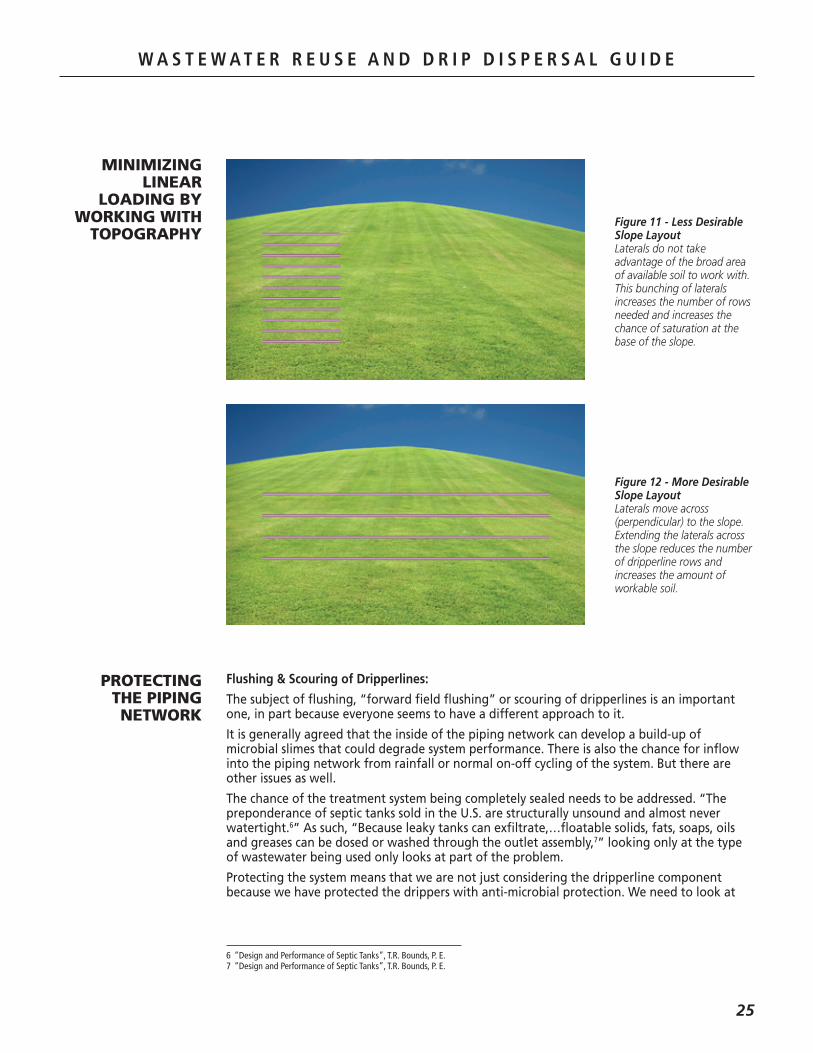
MINIMIZING LINEAR
LOADING BY WORKING WITH
TOPOGRAPHYFigure 11 - Less Desirable Slope Layout Laterals do not take advantage of the broad area of available soil to work with. This bunching of laterals increases the number of rows needed and increases the chance of saturation at the base of the slope.
Figure 12 - More Desirable Slope Layout Laterals move across (perpendicular) to the slope. Extending the laterals across the slope reduces the number of dripperline rows and increases the amount of workable soil.
PROTECTING THE PIPING NETWORK

W A S T E W A T E R R E U S E A N D D R I P D I S P E R S A L G U I D E
26
W A S T E W A T E R R E U S E A N D D R I P D I S P E R S A L G U I D E
the.entire.system.and.consider.the.other.components.that.will.benefit.from.forward.flushing:
•. All.other.piping.beside.the.dripperline
•. Valves
•. Fittings.and.other.velocity-hindering.junctions
Protecting the Bioline® Dripperline
In.order.to.lessen.any.adverse.effects.of.slime.build-up,.Netafim.incorporates.an.antimicrobial.additive.into.the.dripper..This.additive.acts.to.reduce.the.build-up.of.microbial.slimes.and.has.proven.itself.to.be.very.effective..In.addition.to.the.antimicrobial.additive,.designing.the.drip.dispersal.system.to.flush.additional.effluent.at.an.increased.velocity.is.the.norm..The.speed.and.frequency.of.this.action.may.be.a.topic.of.debate,.whether.it.should.be.done.is.not.
Protecting the Rest of the System
The.easiest.and.most.common.method.for.keeping.the.piping.network.and.its.allied.components.operating.in.peak.condition.is.to.design.the.system.so.that.a.flushing.action.can.take.place..This.flushing.action.focuses.on.opening.the.network.up.so.that.additional.flow.can.move.through.the.network.at.an.increased.velocity,.creating.turbulence.and.releasing.any.build-up.that.may.have.occurred.
How Fast You Should Flush
Many.people.look.to.science.to.try.to.get.that.answer..In.terms.of.the.quality.of.effluent,.there.is.data.to.suggest.that.secondary.effluent.may.only.need.a.0.5.-.1.0.fps.velocity.while.raw.wastewater.with.grit.and.other.debris.should.have.anywhere.from.2.5.-.3.5.fps,.and.effluent.following.primary.settling.may.be.in.the.1.5.-.2.0.fps.range..While.the.conservative.nature.of.Netafim.leans.toward.a.higher.flushing.velocity,.the.ultimate.decision.rests.with.local.regulations.and.the.engineer.or.designer.
Designing for a 2 fps Flush Velocity
Designing.for.a.2.fps.flush.velocity.often.does.not.add.any.additional.cost.to.a.system..If.it.does,.it.might.mean.the.minimal.investment.in.an.additional.zone..As.we.have.all.seen.in.life,.the.adage.that.“an.ounce.of.prevention.is.worth.a.pound.of.cure”.usually.wins.out..The.result.of.a.well.designed.and.maintained.system.is.years.of.trouble-free.operation..The.cost.of.cutting.corners.can.ultimately.mean.more.money.spent..When.all.of.the.costs,.from.installation,.to.the.cost.of.the.years.of.service.performed.are.analyzed,.what.may.have.seemed.more.expensive.in.the.beginning.is.really.less.expensive.over.time..That.is.the.principle.behind.Total Cost of Ownership.and.it.is.why.Netafim.encourages.conservative.design.approaches.and.active.professional.maintenance.of.an.onsite.system.
Netafim’s Position on Flush Velocity
Netafim.has.historically.recommended.using.a.2.fps.flushing.velocity..This.rate.correlates.to.a.Reynolds.Number.of.9000.which.is.well.into.the.turbulent.flow.category.(turbulent.flow.with.Bioline.begins.with.0.9.fps)..That.said,.there.is.no.“correct”.number.since.site.and.system.conditions.vary.with.every.system..Among.the.considerations.to.be.studied.are.whether.the.flushing.is.continuous.or.intermittent.and.the.quality.of.the.effluent.
Because.of.the.varying.nature.of.systems.and.the.decision.on.flushing.based.on.regulation.or.designer.belief,.Netafim.provides.Bioline.lateral.length.design.information.for.the.following.velocities:..3.0,.2.5,.2.0,.1.5,.1.0.and.0.5.fps.
Flushing Frequency
The.frequency.of.forward.flushing.is.also.open.to.debate,.but.a.couple.of.factors.help.make.the.decision.easier..Whether.it.is.scheduled.to.be.done.several.times.a.year,.every.25.cycles,.every.15.days,.or.on.a.continuous.basis.is.not.the.issue..Doing.it.and.doing.it.correctly.is.the.issue.

W A S T E W A T E R R E U S E A N D D R I P D I S P E R S A L G U I D E
27
W A S T E W A T E R R E U S E A N D D R I P D I S P E R S A L G U I D E
Dripper Spacing
Dripper Flow Rate (GPH)
Flushing Velocity (fps)
Flow per 100’ (GPM/GPH)
BIOLINE DOSING CHART Maximum Length (feet) of a Single Lateral (2.5 & 3.0 fps)
12”
Inle
t Pre
ssur
e(p
si)
18” 24”
Additional flow of 2.0 GPM required per lateral to achieve 2.5 fps.Additional flow of 2.3 GPM required per lateral to achieve 3.0 fps.
15
25
35
40
45
0.4
2.5 / 3.0
128 / 102
183 / 151
228 / 193
248 / 211
266 / 228
0.67 / 40
0.6
2.5 / 3.0
115 / 94
161 / 136
198 / 171
214 / 186
229 / 200
1.02 / 61
0.9
2.5 / 3.0
100 / 84
137 / 118
166 / 146
178 / 158
190 / 169
1.53 / 92
0.4
2.5 / 3.0
172 / 136
248 / 203
310 / 260
338 / 286
364 / 310
0.44 / 26.67
0.6
2.5 / 3.0
155 / 127
220 / 184
272 / 232
295 / 254
316 / 274
0.68 / 41
0.9
2.5 / 3.0
136 / 113
188 / 161
229 / 200
247 / 218
263 / 233
1.02 / 61
0.4
2.5 / 3.0
205 / 161
301 / 245
379 / 315
413 / 347
447 / 377
0.34 / 20
0.6
2.5 / 3.0
187 / 151
268 / 223
333 / 283
362 / 311
389 / 335
0.51 / 31
0.9
2.5 / 3.0
165 / 137
231 / 197
283 / 245
305 / 267
327 / 287
0.77 / 46
Dripper Spacing
Dripper Flow Rate (GPH)
Flushing Velocity (fps)
Flow per 100’ (GPM/GPH)
BIOLINE DOSING CHART Maximum Length (feet) of a Single Lateral (1.5 & 2.0 fps)
12”
Inle
t Pre
ssur
e(p
si)
18” 24”
Additional flow of 1.2 GPM required per lateral to achieve 1.5 fps.Additional flow of 1.6 GPM required per lateral to achieve 2.0 fps.
15
25
35
40
45
0.4
1.5 / 2.0
201 / 161
266 / 221
316 / 269
337 / 290
358 / 310
0.67 / 40
0.6
1.5 / 2.0
171 / 141
222 / 190
262 / 229
280 / 246
296 / 261
1.02 / 61
0.9
1.5 / 2.0
140 / 119
179 / 157
210 / 187
223 / 200
235 / 212
1.53 / 92
0.4
1.5 / 2.0
275 / 217
366 / 302
437 / 370
469 / 399
497 / 427
0.44 / 26.67
0.6
1.5 / 2.0
235 / 191
308 / 261
365 / 316
391 / 340
413 / 362
0.68 / 41
0.9
1.5 / 2.0
194 / 164
251 / 218
295 / 260
313 / 278
331 / 296
1.02 / 61
0.4
1.5 / 2.0
337 / 263
453 / 369
543 / 455
583 / 493
619 / 527
0.34 / 20
0.6
1.5 / 2.0
289 / 233
383 / 321
455 / 391
487 / 421
517 / 449
0.51 / 31
0.9
1.5 / 2.0
241 / 201
313 / 270
369 / 324
393 / 347
415 / 369
0.77 / 46
Dripper Spacing
Dripper Flow Rate (GPH)
Flushing Velocity (fps)
Flow per 100’ (GPM/GPH)
BIOLINE DOSING CHART Maximum Length (feet) of a Single Lateral (0.5 & 1.0 fps)
12”
Inle
t Pre
ssur
e(p
si)
18” 24”
Additional flow of 0.4 GPM required per lateral to achieve 0.5 fps.Additional flow of 0.8 GPM required per lateral to achieve 1.0 fps.
15
25
35
40
45
0.4
0.5 / 1.0
301 / 248
369 / 315
421 / 367
443 / 389
464 / 409
0.67 / 40
0.6
0.5 / 1.0
242 / 205
296 / 258
337 / 299
354 / 316
371 / 332
1.02 / 61
0.9
0.5 / 1.0
188 / 163
228 / 203
260 / 234
273 / 248
285 / 260
1.53 / 92
0.4
0.5 / 1.0
422 / 344
520 / 440
595 / 513
626 / 545
656 / 574
0.44 / 26.67
0.6
0.5 / 1.0
341 / 285
418 / 361
476 / 419
501 / 445
524 / 468
0.68 / 41
0.9
0.5 / 1.0
265 / 228
323 / 286
368 / 331
387 / 350
404 / 367
1.02 / 61
0.4
0.5 / 1.0
531 / 427
655 / 549
749 / 643
790 / 683
829 / 721
0.34 / 20
0.6
0.5 / 1.0
429 / 355
527 / 453
603 / 527
635 / 559
665 / 589
0.51 / 31
0.9
0.5 / 1.0
335 / 285
409 / 359
467 / 417
491 / 441
513 / 463
0.77 / 46
Table 11 - Maximum Length of a Single Lateral of Bioline Based on Flushing Velocity
W A S T E W A T E R R E U S E A N D D R I P D I S P E R S A L G U I D E
28
DRAINBACK CONSIDERATIONS
When the dosing cycle ends, much of the remaining effluent will drain out of the dripline at or near the closest dripper. (Every 100’ of Bioline only holds 1.33 gallons so the small amount of effluent left in the dripline after shutdown that can drain out of the tubing drains with some evenness over the length of the dripline with little chance for ponding or surfacing.). While this is not a concern with relatively flat areas and areas with subtle rises and-falls, special attention needs to be given to slopes steep enough to create a gravity-driven flow that could force effluent into low areas and thus overload the area or areas with fine textured soils less likely to be able to accept additional flow. To combat this, there are a number of design approaches that address this issue, but the important thing to remember is that caution should be taken to ensure that draindown of the effluent toward the bottom of slopes is minimized.
One of the reasons why Bioline dripperline is a good solution on slopes is due to its pressure compensation feature. Bioline drippers deliver the same flow from 7 to 58 psi, so changes in pressure at the dripper due to elevation-created pressure variances do not affect the delivery rate of the drippers.
Other products allow additional flow anywhere higher pressures exist and as such, the soil can become saturated very quickly at the base of the slope. With Bioline, all areas of the slope are dripped at the same rate. There is no need to increase field size with Bioline. Simply use as much of the slope as possible to deliver to. (See Figures 11 & 12).
Install With the Contour: Dripperline must be installed along the contour of the slope (as level as possible), not up and down the slope. Otherwise, all the effluent in the dripperline will drain rapidly to the emitters at the base of the slope, which can overload the soil.
Feed from the Bottom of the Field: As a rule, drip fields on a slope should be fed from the bottom. This technique will prevent the main lines and manifolds from draining to the field during rest periods. This strategy assumes that the field is uphill from the supply line. The supply manifold should “stair step” through a series of check valves, with a limited number of lines between each check valve. Check valves limit the down gradient flow of the water when the pump shuts down.
Less Frequent, Longer Doses: In more highly permeable soils with no restrictive conditions, longer dosing duration and decreased dosing frequency can help minimize the effects of drainback by reducing the number of cycles per day.
Zone Valves Location: To prevent mainline and submain drainage into the drip dispersal fields, zone valves should be installed as close as possible to the distribution field to minimize the volume of effluent subject to drainback. Local regulations often prohibit effluent from mains and submains draining into the drip fields during periods of rest.
Deeper Line Burial: Another way to manage potential drainback issues and the chance of surfacing is to bury the dripperline deeper. While this is not an optimal solution, it will at least dose the effluent deeper into the soil.

W A S T E W A T E R R E U S E A N D D R I P D I S P E R S A L G U I D E
29
W A S T E W A T E R R E U S E A N D D R I P D I S P E R S A L G U I D E
DOSING AND CONTROLS
The.fundamental.principle.of.drip.dispersal.is.to.take.full.advantage.of.the.entire.application.area.and.to.do.so.over.the.course.of.the.entire.day..Although.most.wastewater.flows.have.peaks.and.valleys.throughout.the.day,.the.goals.of.effective.distribution.are:
•. Minimize.soil.saturation
•. Encourage.lateral.(i.e.,.capillary).rather.than.gravitational.flow.of.effluent
•. Achieve.uniform.distribution
•. Utilize.the.entire.day.(18-24.hours)
Historically,.the.cause.of.most.drip.system.failures.is.not.improperly.designed.drip.fields,.but.rather.an.inadequate.soil.loading.schedule..Experience.has.shown.that.even.a.flow.as.little.as.200.gallons,.dosed.intensively,.can.cause.a.system.failure.in.the.same.field.that.could.accept.500.gallons,.if.dosed.evenly.throughout.the.day.
Time vs. Demand Dosing
The.goals.above.are.best.accomplished.through.effective.dosing.controls.of.an.integrated.system..A.dosing.control.system.is.especially.important.on.tight,.shrink-swell.clay.soils,.since.these.soils.are.very.sensitive.to.overloading.
The.function.and.complexity.of.the.control.system.is.determined.both.by.the.wastewater.demand.and.the.limitations.of.the.soil..An.effective.control.system.considers.the.following:
•. Unusual.loading.conditions
•. Storage.capacity
•. Emergency.storage/malfunction
There.are.two.ways.to.dose.effluent.-.demand.and.time..Demand.dosing.means.that.when.a.tank.is.filled.to.a.certain.point,.a.switch.or.other.device.signals.the.pump.to.turn.on.and.the.effluent.is.dosed.into.the.drip.field..That.continues.until.the.switch.shuts.off.the.pump..
Because.the.system.must.have.adequate.capacity.to.receive.the.flow.and.distribute.it.evenly.over.the.course.of.the.day,.it.is.difficult.to.balance.the.dose.rate.and.the.rest.time.between.doses.with.a.demand.system..Tank.sizing.issues.become.a.critical.component.because.depending.on.its.size,.it.may.lead.to.too.frequent.doses.or.doses.that.operate.too.long..
This.is.the.essence.of.time.dosing.-.pumping.the.effluent.out.at.specified.intervals.throughout.the.day.rather.than.simply.letting.it.flow.out.at.the.same.time.it.is.generated.
Timed.dosing.provides.a.collection.system.and.timer.that.allow.a.specific.amount.of.dosing.to.be.done.at.prescribed.times.throughout.the.day..This.system.is.the.best.way.to.ensure.that.the.soil.is.being.dosed.at.the.proper.rate.and.that.enough.time.elapses.between.doses.for.the.soil.to.manage.the.effluent.
W A S T E W A T E R R E U S E A N D D R I P D I S P E R S A L G U I D E
30
W A S T E W A T E R R E U S E A N D D R I P D I S P E R S A L G U I D E
Netafim.does.not.offer.control.packages.because.many.companies.already.offer.standard.and.customized.controls.to.meet.any.design.criteria.or.specification..The.following.describes.the.general.approach.and.various.levels.of.control.for.a.residential.and.small.commercial.system..Always.consult.local.codes.for.specific.control.requirements.
System.controls.should.be.sophisticated.enough.to.ensure.that.a.sufficient.volume.of.effluent.is.present.in.the.dosing.tank.to.allow.a.time.dose.to.occur.and.that.will.stop.the.dose.event.if.the.level.falls.below.a.sufficient.volume.
Time.Dose.control.panels.are.available.for.use.with.two,.three.or.four.float.combinations..In.a.two.float.system,.one.float.in.the.tank.is.the.“low.level.cutout”.float.while.the.other.is.a.“high.level.alarm”.float..The.normal.operating.level.should.be.between.the.“low.level.cutout”.position.and.the.“high.level.alarm”.position.
Time.Dose.panels.can.be.installed.with.a.choice.of.three.float.systems..One.choice.adds.a.“redundant.off”.float.which.is.positioned.slightly.below.the.“low.level.cutout”.grey.float,.but.above.the.pump..The.normal.operating.level.is.between.the.“low.level.cutout”.position.and.the.“high.level.alarm”.position..The.other.three.float.choice.adds.a.“timer.override”.float.which.is.positioned.between.the.“low.level.cutout”.and.the.“high.level.alarm”.float..Normal.operating.level.should.be.between.the.“low.level.cutout”.float.and.the.“timer.override”.float..
RECOMMENDED DRIP DISPERSAL
OPERATION CONTROLS
An.electronic.control.system.is.essential.to.the.proper.operation.of.a.drip.dispersal.system..The.controller.must.be.able.to.schedule.the.dosing.cycles,.turn.the.dosing.pump(s).on.and.off,.and.may.also.schedule.and.control.the.field.flushing.and.filter.backflush.operations..
While.some.controllers.manage.a.very.sophisticated."headwork".that.doses,.forward.flushes.the.dripperline,.backwashes.the.filters.and.manages.one.or.several.zones,.it.could.also.be.a.more.simple.control.panel.that.performs.the.dosing.cycles,.turns.the.pump(s).on.and.off.and.is.paired.with.a.headwork.unit.that.is.a."continuous.flush".unit.providing.forward.flushing.water.back.to.the.treatment.system.whenever.dosing.is.occurring.
The.breadth.of.control.philosophies.are.only.limited.by.the.creativity.of.the.designer,.the.price.that.the.owner.is.willing.to.pay.and.the.local.regulations.
SEQUENCE OF OPERATION

W A S T E W A T E R R E U S E A N D D R I P D I S P E R S A L G U I D E
31
W A S T E W A T E R R E U S E A N D D R I P D I S P E R S A L G U I D E
HOW TO DOSE
Table 12 - Recommended Dosing Tank Size Based on Bedrooms8
Method 1:
.Add.the.following.elements.together:
•. The.sum.of.the.dosing.volume.
•. The.volume.of.the.delivery.pipes.
•. The.volume.needed.to.keep.the.pump.submerged
•. Emergency.storage.volume.in.case.of.pump.failure..(A.minimum.of.one-day.emergency.storage.above.the.high.water.alarm.is.a.frequently.used.value).
RECOMMENDED DOSING TANK SIZEBased on Bedrooms
1 250
2 250
3 500
4 500
5 750
Number ofBedrooms
Minimum DosingTank Size (gallons)
Method 2:
8 Converse-1978.
The.four.float.system.includes.a.“redundant.off”.float,.a.“low.level.cutout”.float,.a.“timer.override”.float.and.a.“high.level.alarm”.float..The.“timer.override”.float.gives.you.the.option.of.pumping.from.the.basin.while.the.timer.is.in.the.“off”.cycle..It.is.only.intended.for.times.of.abnormally.high.liquid.level.inrushes..The.normal.operating.level.should.be.between.the.“low.level.cutout”.float.and.the.“timer.override”.float..The.control.panel.usually.begins.timing.in.the.“off”.sequence.when.the.“low.level.cutout”.float.is.activated..Once.the.timer.completes.the.“off”.sequence,.the.timer.will.start.the.pump.and.continue.to.run.until.the.programmed.“on”.sequence.is.complete..At.this.point,.the.“off”.sequence.begins.timing.again.and.the.cycle.repeats.
In.addition.to.turning.the.pump.on.and.off.at.specified.times,.the.control.system.typically.enables.the.cleaning.of.filters.and.field.flush.
Before.we.get.too.far.into.dosing,.we.need.to.agree.on.the.volumes.associated.with.a.dose.tank,.what.constitutes.a.single.dose.and.what.constitutes.a.flush.dose,.as.well.as.some.background.on.dose.tank.sizing.
Dose Tank:.The.dose.tank.acts.as.the.storage.vessel.to.accumulate.effluent.that.will.be.dosed.into.the.drip.field..Once.the.effluent.reaches.a.predetermined.volume.or.a.preset.time,.it.is.pumped.to.the.field..The.major.difference.between.a.septic.tank.and.a.dosing.tank.is.that.the.dosing.tank.volume.will.be.lowered.on.a.daily.basis.
Avoid.oversizing.the.dose.tank.because.it.can.be.difficult.to.achieve.adequate.switch.separation.for.the.pump.control..
There.are.different.methods.for.sizing.the.dose.tank..Netafim.does.not.offer.specific.dose.tank.sizing.criteria..The.information.provided.is.only.a.guide..Refer.to.local.regulations.for.proper.sizing.

W A S T E W A T E R R E U S E A N D D R I P D I S P E R S A L G U I D E
32
W A S T E W A T E R R E U S E A N D D R I P D I S P E R S A L G U I D E
Table 13 - Holding Volumes for Various Pipe Sizes
HOLDING VOLUMES in Gallons for Pipe
Pipe Size Per Foot Per 100 Feet
Bioline 0.0133 1.33
1” 0.04 4
1 ¼” 0.07 7
1 ½” 0.1 10
2” 0.17 17
2 ½” 0.24 24
3” 0.38 38
4” 0.65 65
Method 3:
•. Equal.to.what.would.be.required.for.a.septic.tank
•. Should.provide.1.-.2.days.average.flow.equalization.volume
•. On.tough.sites,.increase.the.size.to.ensure.that.the.amount.of.peak.flow.dosing.is.minimized.
•. These.size.systems.usually.work.with.pretreated.effluent
•. Engineers.have.guidelines.on.what.is.adequate
•. The.dose.tank.needs.some.emergency.storage.above.high.water.and.minimum.equalization.storage.for.dosing,.1/3.to.1/2.of.the.daily.flow
•. Equalization.in.the.whole.train.should.exceed.one.day’s.flow
Volume of a Single Dose:.Many.designers.and.regulators.have.established.dosing.times.based.on.dosing.a.minimum.number.of.drip.tubing.volumes.through.the.emitters.(after.pressurization).9.This.ensures.that.the.dosing.cycle.is.long.enough.to.get.good.distribution.of.the.wastewater.into.the.soil..An.effective.minimum.dose.is.generally.regarded.to.be.4.to.6.times.the.liquid.capacity.(volume).of.the.drip.laterals..Refer.to.local.codes.
Volume of a Forward Flush or Flush Dose:.As.we.discussed.earlier.with.flushing.velocities,.the.volume.of.a.flush.dose.is.subject.to.designer.interpretation..In.general,.and.subject.to.local.codes,.it.should.be.at.least.equal.to.or.greater.than.twice.the.void.volume.of.all.pressurized.piping..
Dosing Do’s and Don’ts:
•.Do.not.overdose..Effective.drip.dispersal.relies.on.the.slow,.even.application.of.effluent.to.the.field.
•.Dosing.too.little.could.lead.to.unequal.effluent.distribution.
9 Reference-TVAWastewaterSubsurfaceDripDistributionReport,May2004.Footnote63,page5-26.
DOSE AND FLUSH VOLUMES

W A S T E W A T E R R E U S E A N D D R I P D I S P E R S A L G U I D E
33
W A S T E W A T E R R E U S E A N D D R I P D I S P E R S A L G U I D E
Determining Dosing Requirements:.The.following.provides.the.conceptual.basis.for.sizing.the.drip.field,.setting.up.zones.and.designing.the.pump.control.system..A.computer.spreadsheet.of.this.process.is.available.on.the.Netafim.Wastewater.Division.CD.
1.. How.many.gallons.per.day (GPD) is.the.wastewater.load?
.. Refer to “Typical Wastewater Flows” on page 8 if there is no local rule or criteria.
2.. What.is.the.Soil Loading Rate.in.gallons.per.sq..ft..per.day?.
.. Check.local.rules.and.“Soil.Loading.Rate.Chart”.on.page 18.
3.. Calculate.dispersal.area.
Gallons per day (GPD) ÷ Loading Rate (GPD/sq. ft.) = Application Area (sq. ft.).
4.. Calculate.Total Linear Length of Tubing.
Divide the Application Area by two to get the total linear length of drip tubing (this assumes two foot row spacing between the dripperlines. Divide by 3 for 3 foot spacing, etc.).
5.. Select.Dripper Flow Rate.and.spacing.based.on.soil.type.
. Bioline.is.available.in.flow.rates.of.0.4.GPH,.0.6.GPH.(most.common),.and.0.9.GPH..Heavier.soils.usually.indicate.lower.flow.rate.drippers,.either.0.4.GPH.or.0.6.GPH.
6.. Calculate.Total Flow Rate.of.all.tubing.
. Use.the.chart.“Flow.Rate.per.Length.of.Tubing”.on.page.5,.or.the.following.formula:
Flow Rate of Dripper x Total Linear Length of Tubing ÷ Dripper Spacing (ft.) = Total flow
For example:
- Bioline with 0.6 GPH drippers at 2 ft. spacing between drippers
- For each 1,000 feet of drip tubing, the flow would be: 0.6 x 1000 ÷ 2 = 300 gallons per hour (GPH) = 5 gallons per minute (GPM) [GPH ÷ 60 = GPM].
7.. Determine.the.Number of Zones.needed.by.pump.size.consideration.
. Zones.should.generally.not.exceed.half.the.rated.volume.of.the.pump.
8.. Calculate.Total Flow Rate per Zone.in.gallons.per.minute.(GPM).
.. Total.flow.rate.of.all.tubing.÷.number.of.zones.
9.. Calculate.Number of Minutes of Total Run Time.based.on.daily.flow.
.. Total.Daily.Load.(GPD)
. Number.of.Zones
10.. Calculate.Number of Minutes per Zone.
.. Total.Minutes
. Number.of.Zones
11.. Select.Dosing Duration.based.on.soil.conditions.(6.to.12.minutes):
.. Typically,.heavier.soils.should.have.shorter.dosing.durations.
12.. Determine.Number of Dosing Events:
. Number.of.minutes.of.total.runtime.÷.dose.duration.(minutes).
13.. Calculate.Time Between Dosing Events:
. Based.on.an.18.hour.day.(check.local.regulations)..Time.between.dosing.events.=
.. 18
. Number.of.Doses.plus.1

W A S T E W A T E R R E U S E A N D D R I P D I S P E R S A L G U I D E
34
W A S T E W A T E R R E U S E A N D D R I P D I S P E R S A L G U I D E
Disc Filters:.Disc.filters.fall.into.the.category.of."depth".filters.because.they.add.an.additional.dimension.to.the.cleaning.process..Disc.filters.use.an.overlapping.series.of.grooves.that.force.the.effluent.to.move.through.a.series.of.trap.points..This.process.increases.the.likelihood.of.debris.capture.to.90%.-.99%..Because.of.the.increase.in.filtration.surface.area,.the.frequency.of.cleaning.drops.and.cleaning.is.easier.
Netafim.recommends.disc.filtration.for.standard.residential.and.small.commercial.onsite.wastewater.drip.dispersal.systems.
Media Filters:.Media.filters.offer.the.greatest.protection.against.both.organic.and.inorganic.debris..In.a.media.filter,.raw.water.is.introduced.into.a.filter.chamber.that.is.filled.with.a.media.such.as.sand.and.is.allowed.to.pass.through.the.media.bed..The.media.does.an.excellent.job.of.capturing.the.debris.and.is.superb.at.delivering.highly.filtered.water..In.applications.where.even.finer.filtration.is.required,.varying.types.and.layers.of.media.can.be.
The.filter.is.designed.to.capture.particles.larger.than.can.safely.pass.through.the.drip.emitters..
The.most.common.filtration.methods.in.use.today.in.onsite.systems.are:
•. Screen
•. Disc
•. Media
Screen Filters:.Screen.filters.are.the.least.sophisticated.filters.for.use.in.onsite.systems.because.they.are.the.most.likely.to.allow.debris.to.pass.through.them..This.is.especially.true.of.organics.which.can.change.shape.and.be.squeezed.through.the.filter.during.operation..Screen.filters.also.have.a.much.smaller.surface.area.than.other.types.of.filters.which.increases.the.frequency.of.cleaning..In.general,.screen.filters.only.capture.about.65%.of.the.debris.at.or.above.its.stated.micron.size.and.the.cleaning.operation.is.difficult.because.the.debris.is.typically.wedged.into.the.spaces.of.the.screen..This.means.that.the.screen.cannot.be.effectively.surface.flushed..It.needs.to.be.removed.and.physically.scrubbed.and.it.is.very.difficult.to.remove.the.debris.jammed.into.the.screen.
FILTERS AND FILTER CLEANING
Figure 13 - Screen Filter with Debris Passing Through
This picture illustrates how debris can easily pass through the single layer structure of a screen filter.
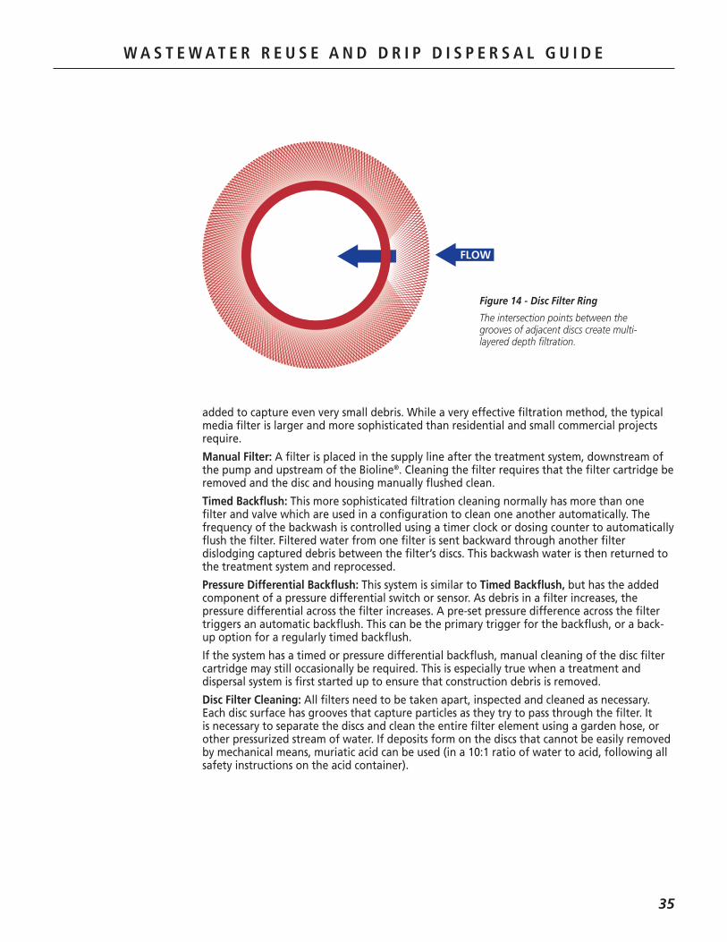
W A S T E W A T E R R E U S E A N D D R I P D I S P E R S A L G U I D E
35
W A S T E W A T E R R E U S E A N D D R I P D I S P E R S A L G U I D E
FLOW
Figure 14 - Disc Filter Ring
The intersection points between the grooves of adjacent discs create multi-layered depth filtration.
added.to.capture.even.very.small.debris..While.a.very.effective.filtration.method,.the.typical.media.filter.is.larger.and.more.sophisticated.than.residential.and.small.commercial.projects.require.
Manual Filter:.A.filter.is.placed.in.the.supply.line.after.the.treatment.system,.downstream.of.the.pump.and.upstream.of.the.Bioline®..Cleaning.the.filter.requires.that.the.filter.cartridge.be.removed.and.the.disc.and.housing.manually.flushed.clean.
Timed Backflush:.This.more.sophisticated.filtration.cleaning.normally.has.more.than.one.filter.and.valve.which.are.used.in.a.configuration.to.clean.one.another.automatically..The.frequency.of.the.backwash.is.controlled.using.a.timer.clock.or.dosing.counter.to.automatically.flush.the.filter..Filtered.water.from.one.filter.is.sent.backward.through.another.filter.dislodging.captured.debris.between.the.filter’s.discs..This.backwash.water.is.then.returned.to.the.treatment.system.and.reprocessed.
Pressure Differential Backflush:.This.system.is.similar.to Timed Backflush,.but.has.the.added.component.of.a.pressure.differential.switch.or.sensor..As.debris.in.a.filter.increases,.the.pressure.differential.across.the.filter.increases..A.pre-set.pressure.difference.across.the.filter.triggers.an.automatic.backflush..This.can.be.the.primary.trigger.for.the.backflush,.or.a.back-up.option.for.a.regularly.timed.backflush.
If.the.system.has.a.timed.or.pressure.differential.backflush,.manual.cleaning.of.the.disc.filter.cartridge.may.still.occasionally.be.required..This.is.especially.true.when.a.treatment.and.dispersal.system.is.first.started.up.to.ensure.that.construction.debris.is.removed.
Disc Filter Cleaning:.All.filters.need.to.be.taken.apart,.inspected.and.cleaned.as.necessary..Each.disc.surface.has.grooves.that.capture.particles.as.they.try.to.pass.through.the.filter..It.is.necessary.to.separate.the.discs.and.clean.the.entire.filter.element.using.a.garden.hose,.or.other.pressurized.stream.of.water..If.deposits.form.on.the.discs.that.cannot.be.easily.removed.by.mechanical.means,.muriatic.acid.can.be.used.(in.a.10:1.ratio.of.water.to.acid,.following.all.safety.instructions.on.the.acid.container).

W A S T E W A T E R R E U S E A N D D R I P D I S P E R S A L G U I D E
36
W A S T E W A T E R R E U S E A N D D R I P D I S P E R S A L G U I D E
ROOT INTRUSION The.unique.design.characteristics.of.the.Bioline.emitter.provide.an.effective.physical.barrier.against.root.intrusion.without.the.addition.of.root.inhibiting.chemicals..Bioline®.dripperline.has.a.Full Ten-year Warranty.against.clogging.due.to.root.intrusion..
If.local.regulations.require.the.addition.of.a.root.intrusion.inhibiting.chemical,.or.if.the.designer.or.system.owner.or.operator.want.an.extra.measure.of.assurance,.Netafim.can.provide.the.Techfilter®.System..Techfilter.incorporates.a.replaceable.filter.element.embedded.with.trifluralin11,.an.effective.root.inhibiting.chemical.used.extensively.in.agriculture..As.water.passes.through.the.filter,.a.very.low.concentration.of.trifluralin.(parts.per.billion).passes.through.the.system..This.technology.provides.very.precise.and.even.distribution.of.trifluralin.throughout.the.piping.network.which.is.not.possible.when.the.dripper.is.impregnated.with.the.chemical.
Unlike.other.products,.Techfilter.eliminates.skin.irritation.from.the.chemical.during.handling,.and.does.not.require.that.tubing.be.stored.in.a.dry,.cool.building.out.of.the.sun.
Techfilter®.is.designed.to.provide.renewable.protection.because.the.chemical.is.both.heat.and.time.sensitive..As.it.loses.its.effectiveness.over.time,.it.can.be.replaced,.and.as.such,.when.prescribed.maintenance.of.the.Techfilter.is.performed,.a.limited.Lifetime Warranty.against.root.intrusion.is.available.
FIELD FLUSH Netafim.Bioline®.dripperline.is.designed.to.last.for.many.years..Although.filtration.is.taking.place,.small.particles.(under.130.microns).can.still.enter.the.tubing..Over.time,.these.particles.may.accumulate..As.such,.it.is.recommended.to.field.flush.the.system.
As.discussed.earlier,."field.flushing",."forward.flushing".or."scouring".is.accomplished.by.either.continuously.flushing.or.by.periodically.opening.the.flush.line.from.the.drip.field.back.to.the.pretreatment.or.dosing.tank..In.this.process,.the.velocity.of.water.moving.through.the.tubing.is.increased.to.a.rate.of.speed.(velocity).that.breaks.any.debris.build-up.free.from.the.walls.of.the.piping.network.and.sends.it.back.to.either.the.dose.tank.(when.doing.continuous.flush).or.the.beginning.of.the.treatment.system.(when.doing.intermittent.flush)..The.dirtier.the.water,.the.higher.the.recommended.flush.velocity.and.frequency.be..To.prevent.an.accumulation.of.debris.in.the.dripperline,.it.is.recommended.that.field.flushing.take.place.on.a.regular.basis..Field.flushing.should.be.done.at.least.several.times.per.year,.but.the.system.may.be.designed.with.a.simple.continuous.flush.headwork.that.allows.a.constant.flow.of.water.back.to.the.dose.tank,.thus.providing.for.a.continuous.scouring.action10..The.required.rate.will.depend.on.many.factors..Among.these.are:
•. Effluent.quality.and.characteristics
•. Filtration.efficiency
•. Length.of.tubing.in.each.zone
•. Local.regulations.for.maintenance
10 Seetheearlierdiscussiononthistopic.11 Trifluralinstopscelldivisioninanyroottipthatcomesintoanareawherethechemicalispresent.

W A S T E W A T E R R E U S E A N D D R I P D I S P E R S A L G U I D E
37
W A S T E W A T E R R E U S E A N D D R I P D I S P E R S A L G U I D E
INSTALLATION SITE PREPARATION
The.drip.field.should.be.viewed.as.a.wastewater.dispersal.field.and.many.of.the.same.considerations.for.conventional.septic.drain.fields.should.apply..These.limitations.include:
•.No.future.expectation.of.building(s),.decks,.or.other.impervious.surfaces
•.No.long.term.storage.of.equipment.or.vehicles.over.the.site
•.A.permanent.vegetative.cover
•.Winter.dormant.grasses.are.over-seeded.with.winter.grasses.when.possible
DRIP TUBING INSTALLATION
One.of.the.prime.benefits.of.Bioline®.is.its.ability.to.deliver.effluent.at.a.prescribed.rate.into.the.biologically-active.layer.of.the.soil.that.supports.the.roots.of.plants,.trees.and.turfgrass..In.conjunction.with.the.effluent-purifying.capabilities.of.the.soil,.the.root.systems.provide.valuable.uptake.of.the.effluent.as.well..
To.maximize.the.soil’s.biological.activity,.the.drip.tubing.will.normally.be.installed.8.to.12.inches.below.the.soil.surface..Check.local.codes.for.depth.of.burial.
Colder.climates.may.require.deeper.placement.or.additional.cover.to.avoid.freezing.during.periods.of.inactivity.
Where.conditions.allow,.manifold.trench.depth.should.be.the.same.as.the.dripperline.depth.in.order.for.the.air/vacuum.relief.valves.to.work.most.effectively..In.freezing.climates,.manifolds.may.have.to.be.placed.below.the.frost.line.
Dig.the.manifold.trenches.wide.enough.to.provide.sufficient.working.room.to.cut.and.fit.tees.and.to.insert.the.flex.connectors.between.the.manifolds.and.the.tubing..Allow.enough.room.to.work..Always.avoid.installing.drip.tubing.in.wet.soil.
Three common ways to install the Bioline drip tubing:
Plowing:.Installed.much.the.same.way.as.TV.cable,.plowing.refers.to.knifing.in.the.dripperline.through.use.of.a.vibratory.plow..This.method.is.increasingly.common.because.the.process.does.not.disturb.the.soils.and.smearing.is.uncommon.
Netafim.works.closely.with.Vermeer.Manufacturing.Company.and.together.they.have.developed.a.vibratory.plow.that.efficiently.installs.several.rows.of.Netafim.Bioline.at.once.
The.process,.called.Conservigation®.is.exclusive.to.Netafim.and.is.the.most.sophisticated.installation.process.on.the.market..

W A S T E W A T E R R E U S E A N D D R I P D I S P E R S A L G U I D E
38
W A S T E W A T E R R E U S E A N D D R I P D I S P E R S A L G U I D E
Figure 15 - The MB-40 Multi-Blade Vibratory Plow. Shown here with three 1,000’ rolls of Netafim Bioline® attached to the versatile Vermeer® LM-42 power unit. This unit has a variety of attachments and fits into narrow areas.
Figure 16 - MB-40 Minimizes Damage to Existing Landscape. Thanks to its unique design, the MB-40 quickly rake-up of this area, the rows virtually disappear.
Figure 18 - MB-40 Can Be Mounted on the Vermeer® RTX-450. This ride-on unit is excellent for large installations.
Figure 17 - MB-40 Does Not Disturb the Grade. Even in bare dirt.

W A S T E W A T E R R E U S E A N D D R I P D I S P E R S A L G U I D E
39
W A S T E W A T E R R E U S E A N D D R I P D I S P E R S A L G U I D E
Trenching:.This.method.uses.commonly.available.trenching.machines.to.cut.narrow.trenches.for.tubing.installation..The.advantages.of.this.method.are.that.trenchers.are.widely.available.and.easy.to.use..The.disadvantages.are.that.the.trench.may.leave.wall.surfaces.that.are.“slicked”.and.therefore.less.receptive.to.horizontal.water.flow..Trenching.will.damage.existing.vegetation;.the.trenches.must.be.filled.with.original.materials,.properly.compacted,.and.watered.in.from.the.top.down.
Fill or “Drip and Fill”: In.this.method,.the.dripperline.is.laid.on.the.ground.and.fill.material.is.placed.over.it..If.there.is.any.vegetative.cover,.it.should.be.removed.and.the.original.soil.scarified.(plowed.or.deep-raked).to.minimize.any.variances.in.soil.types..If.soils.of.different.textures.are.used,.the.constraints.discussed.in.the.Soils.Section.must.apply..It.is.recommended.that.the.fill.material.be.the.same.as.the.original.
Other.tips.when.using.imported.soil.include:
1.. Use.soil.with.a.clay.content.not.exceeding.20%
2.. Harvest,.ship.and.place.the.soil.only.under.dry.conditions
3.. Remove.all.debris,.roots.and.other.coarse.fragments.or.rocks
4.. Put.the.soil.in.place.in.6”.-.8”.increments
Netafim.has.a.technical.paper.titled.“Guidelines.for.Using.Imported.Soil”.in.the.literature.download.section.of.the.Netafim.Wastewater.website..It.contains.important.information.to.consider.when.using.imported.soil.
Figure 20 - Mechanized Equipment May be used
to spread soil over the top in larger systems. It is
important to evenly spread the soil moving with the
tubing direction to keep the laterals from shifting.
Figure 19 - "Drip and Fill" Technique.The dripperline is laid out across the drip field and fill material is then placed over the dripperline to the prescribed depth.

W A S T E W A T E R R E U S E A N D D R I P D I S P E R S A L G U I D E
40
W A S T E W A T E R R E U S E A N D D R I P D I S P E R S A L G U I D E
For.all.methods,.it.is.important.that.the.disturbed.soil.above.the.dripperline.be.the.approximate.texture.and.compaction.as.the.soil.around.the.dripperline..This.will.avoid.creating.a.preferential.pathway.of.the.effluent.to.the.surface,.also.known.as.the."Chimney.Effect"..Careful,.manual.compaction.of.the.soil.above.the.dripperline.may.be.advisable.when.the.tube.has.been.trenched.or.plowed.in.(local.codes.permitting).
NOTE: Avoid excessive mechanical stress on the tubing before, during, and after installation.
PIPING HOOK-UP
The.supply.and.flush.lines,.and.the.supply.and.flush.manifolds.are.installed.using.standard.techniques.for.PVC.piping..Medium.body.(not.fast.drying).PVC.cement.is.generally.preferred.
Use.the.primer.and.cement.as.recommended.by.the.manufacturer.
The.installer.should.use.a.good.quality,.ratcheting.type.PVC.cutter.to.prevent.PVC.filings.from.getting.into.the.distribution.lines.
OPERATION AND MAINTENANCE
START-UP
The.designer.should.take.precautions.to.troubleshoot.the.system.and.ensure.that.it.is.working.properly.over.an.initial.startup.period,.typically.2.to.3.weeks.
Do.not.start.the.system.with.a.massive.dose..This.can.cause.preferential.water.passages,.or.chimneys,.that.allow.the.effluent.to.surface.and.saturate.the.soil..If.this.happens,.it.may.take.some.time.to.recover.the.drip.field.
Construction.debris.(PVC.scraps,.glue.remnants,.soil,.etc.).found.in.the.piping.network.needs.to.be.flushed..This.flushing.should.not.be.done.through.the.dripperline.but.rather.before.the.dripperlines.are.connected.to.the.headers..If.the.dripperlines.are.already.connected.to.the.headers,.do.not.exceed.the.scheduled.dosing.cycle.while.flushing.
The.pump.tank.or.treatment.system.may.be.full.of.water.after.installation..Do.not.simply.run.it.out.through.the.drip.tube..Either.use.the.dosing.schedule.to.empty.the.tank.or.set.up.a.sprinkler,.but.always.follow.local.codes.as.they.apply.
If.the.dosing.field.is.extremely.dry,.it.can.be.advantageous.to.run.a.sprinkler.on.the.surface.to.initially.dampen.the.field.
ROUTINE MAINTENANCE
Service.and.maintenance.of.the.system.should.be.coordinated.with.any.regulatory.requirements.for.monitoring.of.the.onsite.system..Most.states.have.regulations.that.specify.a.routine.maintenance.schedule.for.advanced.onsite.wastewater.treatment.systems.
When.a.drip.dispersal.system.is.properly.sized,.designed,.and.installed,.it.should.operate.with.little.maintenance.and.easy.monitoring..In.addition.to.the.fundamental.design.considerations.already.outlined,.several.other.installation.steps.will.simplify.maintenance..These.include:
1.. Provide.nipples.for.Schrader.valves.(tire.gauge.stems.for.measuring.pressure).on.critical.piping.elements.(pump.output,.supply.and.flush.manifolds,.inlet.and.outlet.of.filters,.etc.).in.valve.boxes.to.provide.easy.measurement.of.system.pressure.
2.. Maintain.access.to.a.short.length.of.drip.tubing.for.inspection.
3.. Keep.a.detailed.plot.plan,.system.diagram,.and.wiring.diagram.readily.accessible.in.the.control.panel.
W A S T E W A T E R R E U S E A N D D R I P D I S P E R S A L G U I D E
41
W A S T E W A T E R R E U S E A N D D R I P D I S P E R S A L G U I D E
TYPICALLAYOUTS
TYPICAL LAYOUTS FOR RESIDENTIAL AND SMALL COMMERCIAL SYSTEMS
The.layout.for.a.typical.residential.onsite.system.is.comprised.of.several.components..In.the.following.illustrations,.each.design.scenario.will.contain.all.or.part.of.the.following.components.and.systems:
•. Secondary.treatment.system.-.advanced.treatment.unit,.recirculating.sand.filter,.peat.system,.fixed.film,.or.wetland.system,.etc.
•. Pump.or.dosing.tank.with.water.level.sensors
•. Pump
•. System.controller.for.pump.operations,.zone.control,.dosing.scheduling,.dosing.tank.monitoring,.filter.backflushing,.field.flushing.and.alarms
•. Automatic.or.manual.disc.filter.(130.micron./.120.mesh).set.in.an.access.box
•. Air/Vacuum.Relief.Valves
•. Zone.Control.Valves.-.Water.actuated,.motor.driven.or.solenoid.activated.hydraulic.valve
•. Underground.PVC.piping,.often.1¼".mainline,.header.and.return.lines
•. Flexible.PVC.connectors.and.loops
•. Mainline.and.supply.header
•. Flush.manifold.and.return.line
•. Check.valves
•. Bioline®.drip.dispersal.tubing
The.following.layouts.illustrate.some.of.the.ways.that.drip.dispersal.fields.can.be.laid.out.at.a.residence.or.small.commercial.complex..Use.these.drawings.as.guides.only..Each.system.will.have.special.circumstances.that.will.require.the.designer.to.modify.these.typical.layouts.in.order.to.adapt.to.the.site..The.following.are.basic.considerations.that.should.be.taken.prior.to.beginning.any.design:
•. Shape.of.the.proposed.drain.field
•. General.slope.or.direction.of.rise.and.fall.of.the.site
•. Location.of.property.lines,.buildings,.trees,.wells,.water.lines,.gas.lines,.buried.power.lines,.swimming.pools,.etc.
•. Soil.type.including.profiling.to.determine.depth.to.most.restrictive.layer.and.or.water.table
4.. Establish.a.service.record.chart.to.record:
• Pressure at: • Schedule:. -.Pump. -.Dosing. -.Supply.line.or.manifold. -.Filter.flushing. -.Flush.line.or.manifold. -.Field.flushing. -.Other.critical.points
5.. Monitor.any.changes.in.the.number,.activities,.and.water.usage.patterns.of.members.of.the.household.
With.this.information.framework,.a.system.inspector.can.quickly.and.easily.determine.if.the.system.is.operating.within.specifications..If.problems.are.identified.by.changes.in.pressure.or.flow,.they.can.be.located.and.corrected.easily.using.information.in.the.plans.and.locations.of.valve.boxes.

W A S T E W A T E R R E U S E A N D D R I P D I S P E R S A L G U I D E
42
W A S T E W A T E R R E U S E A N D D R I P D I S P E R S A L G U I D E
•. Location.of.treatment.system
•. Location.of.power.outlets.or.breaker
•. Location.of.old.drain.field.if.the.new.system.is.a.retrofit
OPPOSING MANIFOLD LAYOUT
Rectangular.field.with.supply.and.flush.manifolds.at.opposite.ends.of.dripperlines:
•. Can.be.used.where.Bioline®.lengths.will.be.long.and.the.drip.field.is.narrow
•. Bioline®.laterals.should.never.exceed.recommended.lengths
Secondary Treatment and Storage
Residence
Disc Filter
Supply Line Air/VacuumRelief Valve
Flush Valve
Flush Line Bioline®
Dripperline
Supply Line
Flush Line
Netafim Bioline
Air/VacuumRelief Valve
Flush Valve
Disc Filter
Key
or

W A S T E W A T E R R E U S E A N D D R I P D I S P E R S A L G U I D E
43
W A S T E W A T E R R E U S E A N D D R I P D I S P E R S A L G U I D E
SINGLE TRENCH LAYOUT
Rectangular.field.with.supply.and.flush.manifolds.on.the.same.side.and.in.the.same.trench:
•. Locate.the.supply.and.flush.manifolds.in.the.same.trench
•. Dripperlines.are.looped.at.the.halfway.point.of.their.run.and.returned.to.flush.manifold
•. Bioline®.laterals.should.never.exceed.recommended.lengths
Secondary Treatment and Storage
Residence
Disc Filter
Supply Line
Flush Valve
Bioline®
Dripperline
Flush Line
or
Air/VacuumRelief Valve
Supply Line
Flush Line
Netafim Bioline
Air/VacuumRelief Valve
Flush Valve
Disc Filter
Key

W A S T E W A T E R R E U S E A N D D R I P D I S P E R S A L G U I D E
44
W A S T E W A T E R R E U S E A N D D R I P D I S P E R S A L G U I D E
IRREGULAR FIELD SHAPE LAYOUT
Triangular.field.with.looping.and.varied.positioning.of.flush.manifolds:
•. Used.when.site.limitations.dictate.unequal.dripperline.length.with.respect.to.dispersal.field.length
•. Loop.the.Bioline®.to.increase.lateral.length.and.reduce.the.number.of.connections
•. Keep.the.Bioline.laterals.as.close.to.the.same.length.as.possible.to.provide.for.an.equal.field.flush
•. The.flush.manifold.may.be.located.on.the.same.or.opposite.side.of.the.supply.manifold
•. As.pictured,.it.may.be.necessary.to.make.one.or.more.distal.end.connections.to.the.flush.line.on.an.opposing.side.in.order.to.balance.dripperline.lateral.lengths.and.to.limit.the.number.of.connections
Secondary Treatment and Storage
Residence
Disc Filter
Flush Valve
or
Flush Line
Bioline®
Dripperline
Supply Line
Air/VacuumRelief Valve
Supply Line
Flush Line
Netafim Bioline
Air/VacuumRelief Valve
Flush Valve
Disc Filter
Key

W A S T E W A T E R R E U S E A N D D R I P D I S P E R S A L G U I D E
45
W A S T E W A T E R R E U S E A N D D R I P D I S P E R S A L G U I D E
MULTIPLE ZONE LAYOUT
Multiple.zone.system.with.looping.laterals:
•. Used.for.a.variety.of.reasons.including.when:
. -. Single.zone.accumulated.Bioline®.lengths.exceed.recommended.pump.flow.rate
. -. Soils.require.additional.resting.time.between.dosings
. -. There.is.a.potential.need.for.expansion.of.the.system,.which.is.common.in.commercial.. .
. . systems..Second.or.subsequent.zone.may.be.left.out.until.needed
•. Additional.check.valves.are.needed.to.isolate.each.zone.on.the.flush.line.side..An.additional.air/vacuum.relief.valve.should.be.installed.before.the.check.valve.on.each.zone
•. Zone.changes.are.typically.accomplished.using.an.electric.valve.and.controller
•. Zone.layouts.may.be.parallel.systems.or.may.follow.any.of.the.scenarios.discussed
•. Zones.should.have.similar.flows.
•. Controller.must.be.capable.of.operating.a.multi-zone.system
Secondary Treatment and Storage
Supply Line
Flush Line
Netafim Bioline
Air/VacuumRelief Valve
Flush Valve
Disc Filter
Check Valve
Key
Residence
Disc Filter
Flush ValveZone Valves Supply Lines
Check Valve
Air/VacuumRelief Valve
Check Valve
or
Bioline® Dripperline

W A S T E W A T E R R E U S E A N D D R I P D I S P E R S A L G U I D E
46
W A S T E W A T E R R E U S E A N D D R I P D I S P E R S A L G U I D E
FREEZING CLIMATE DESIGN
AND OTHER CONSIDERATIONS
The.goal.of.freezing.climate.designs.is.to.be.able.to.drain.the.entire.system.as.quickly.as.possible.-.preferably.in.10.to.15.minutes.or.less..Any.pipe.or.component.that.does.not.drain.after.a.dose.must.be.buried.below.the.frost.line.and/or.properly.insulated.
Landscape and Cover:
1.. Additional.depth.over.dripperline:
. a.. Dripperlines.that.are.buried.deeper.in.the.ground.are.less.likely.to.freeze.than.shallow.
. b.. Whenever.possible,.add.solid.cover.(soil).to.increase.the.depth.of.the.dripperline..
. c.. Note:.It.is.better.to.have.the.dripperlines.in.the.6”.-.8”.range.if.possible.for.better.. .. nutrient.removal,.but.this.should.be.weighed.against.the.climate.
2.. Established.and.undisturbed.wooded.sites.where.trees.have.not.been.removed,.have.been.shown.to.allow.shallow.systems.to.perform.without.freezing.12
3.. Landscapes.with.drip.dispersal.fields.should.have.vegetative.cover.over.them..This.may.be.prairie.grass,.plants,.bushes,.shrubs,.trees,.turfgrass.or.any.combination.
4.. Vegetative.height.should.be.at.least.4”.to.6”.
5.. In.areas.where.warm.season.grasses.go.dormant:
. a.. The.area.should.be.overseeded.to.ensure.sufficient.ground.cover.
. b.. Overseeding.should.begin.as.early.as.possible.to.allow.enough.growth.
. c.. Cover.all.areas.with.at.least.6”.of.straw/hay.until.the.cover.is.properly.. . .. established.
6.. Stop.mowing.operations.as.early.as.possible.so.grasses.can.grow.as.tall.as.possible.
7.. Managing.snow.cover:
. a.. Because.snow.is.an.excellent.insulator,.provisions.should.be.made.to.ensure.that.snow.... can.stay.in.place.over.the.drip.field..
. b.. Use.anything.that.will.help.the.snow.to.accumulate.and.stay.over.the.field,.including.. .. snow.fence.or.other.fencing,.stands.of.trees,.bushes,.hedges,.or.decorative.grasses..
8.. In.windy.areas.it.may.be.necessary.to.have.more.than.turfgrass.as.a.cover.
9.. If.it.is.not.possible.to.grow.a.cover.over.the.field,.use.at.least.6”.of.straw/hay.to.cover.the.entire.system..In.areas/seasons.with.minimum.snow.cover,.check.the.depth.of.the.straw/hay.during.the.season..Add.more.cover.as.needed.
10..Keep.foot.traffic.away.from.the.drip.field,.especially.when.it.has.a.snow.cover.
Headers and Dripperline:
1.. Note:.Netafim.Bioline®.dripperline.is.made.from.low-density,.linear.polyethylene.to.weather.the.effects.of.cold.weather..Due.to.its.emitters,.it.will.drain.available.effluent.after.dosing..Our.design.and.operation.efforts.therefore.are.to.protect.the.non-Bioline.piping.network,.fittings,.valves.and.hard/rigid.components.that.can.break.or.fail.if.frozen.
2.. Manifolds.and.supply/return.lines.should.be.installed.lower.than.dripperlines.to.provide.positive.drainback.after.the.zone.shuts.off.
12 Mokma,D.L.,T.L.Loudon&P.Miller.2001Rationalforshallowtrenchesinsoiltreatmentsystems.In:OnsiteWastewaterTreatment.Proceedingsofthe9thNationalSymposiumonIndividualandSmallCommunitySewageSystems.ASAE.2950NilesRoad,St.Joseph,MI.www.asae.org

W A S T E W A T E R R E U S E A N D D R I P D I S P E R S A L G U I D E
47
W A S T E W A T E R R E U S E A N D D R I P D I S P E R S A L G U I D E
3.. Manifolds.and.supply/return.lines.should.be.sloped.back.to.the.tank.to.provide.positive.drainback.
4.. Under.extreme.conditions,.manifolds.and.supply/return.lines.should.be.buried.below.the.frost.line.
5.. Consider.insulating.all.manifolds.and.supply/return.lines.with.Styrofoam.board.if.the.system.is.in.an.extremely.cold.location.
6.. Any.drain.valves.must.be.able.to.remain.open.long.enough.for.the.entire.field.to.drain..Note:.Hydraulically-operated.valves.may.close.when.system.pressure.is.too.low.
7.. Motorized.drain.valves.may.be.installed.to.help.drain.the.system.in.lieu.of.hydraulic.valves.
8.. Dripperline.should.be.installed.level.across.the.contour.of.any.discernible.slope.
9.. On.laterals.with.blank.tubing.or.flex.connections,.they.may.be.installed.slightly.above.the.dripperlines..This.will.allow.them.to.drain.into.the.dripperline.laterals.
10..Consider.using.larger.piping.on.the.supply.and.return.lines.to.accommodate.a.high.pressure.nozzle.and.tubing.along.with.clean.out.ports.to.gain.entrance.into.the.system..There.are.several.brands.of.water.jets.on.the.market.that.can.clear.ice.from.inside.the.headers..They.rely.on.warm.water.and.its.special.nozzling.allows.it.to.move.forward.in.the.pipe.as.the.stream.of.water.dislodges.any.blockages.
Air Vents / Headworks / Valves / Valve Boxes:
1.. Install.larger.valve.boxes.than.would.normally.be.used.to.accommodate.any.service.work.that.may.be.done.in.the.winter.
2.. Insulate.all.equipment.boxes,.including.headworks.boxes,.filters,.field.flush.valve.boxes,.as.well.as.zone.dosing.valves.and.air/vacuum.relief.valves..Use.Styrofoam.panels.or.chips,.or.other.closed.cell.insulating.materials.such.as.perlite.or.vermiculite.in.bags.around.the.inside.and.the.outside.of.valve.boxes..If.fiberglass.is.used,.ensure.that.it.cannot.become.waterlogged.
3.. Install.headworks.and.other.components.in.risers.over.the.treatment.tank.to.capture.available.warmth.
4.. Design.the.system.around.providing.a.continuous.flush..This.will.keep.water.moving.throughout.the.system.during.a.dose.and.allow.for.fast.draining.on.shutdown.
5.. Insulate.or.add.a.heater.to.the.headworks.
6.. If.using.an.index.valve.to.split.field.zones,.be.sure.it.is.capable.of.draining.
7.. Air/Vacuum.Relief.Valves.should.be.used.liberally,.and.at.least.on.the.end.of.supply.and.flush.manifolds.
8.. Air/Vacuum.Relief.Valves.should.be.placed.below.grade.at.any.high.point(s).and.always.above.any.dripperline.laterals..The.top.of.A/VRV.must.be.no.higher.than.the.soil.surface..
9.. Attach.and.secure.something.metallic.to.the.lid.of.valve.boxes.and.A/VRV.boxes.to.make.them.easier.to.find.when.they.are.covered.with.snow.or.vegetation.
10..Add.a.gravel.sump.of.at.least.6”.under.any.valve.box.
11..Grade.away.from.all.valve.boxes.to.reduce.groundwater.incursion.
Installation:
1.. As.noted.above,.dripperline.laterals.on.any.discernible.slope.should.be.installed.as.close.to.contour.as.possible.

W A S T E W A T E R R E U S E A N D D R I P D I S P E R S A L G U I D E
48
W A S T E W A T E R R E U S E A N D D R I P D I S P E R S A L G U I D E
2.. Due.to.potential.shrinkage.of.the.dripperline.in.cold.weather,.it.should.be.installed.so.there.is.slack.in.the.tubing..“Weaving”.it.back.and.forth.if.being.installed.in.an.open.trench.is.an.acceptable.method..
3.. If.repairs.are.made.to.the.system,.keep.the.dripperline.from.becoming.taut.by.adding.sufficient.tubing.so.the.dripperline.is.not.stretched.
4.. Insulate.the.septic/treatment.tank.and.pump.tank.to.preserve.whatever.heat.is.inside.
5.. All.electrical.components.must.be.properly.sealed.to.prevent.condensation.getting.inside.any.controllers.or.panels.
6.. Position.and.angle.all.filters.to.ensure.that.water.does.not.get.trapped.inside.
7.. Remove.the.check.valve.at.the.pump.
Operation:
1.. In.multi-zone.systems.with.lower.flows.in.the.winter,.reduce.the.number.of.zones.being.used.
2.. Reduce.the.time.between.doses,.but.do.not.overload.the.soil.

W A S T E W A T E R R E U S E A N D D R I P D I S P E R S A L G U I D E
49
W A S T E W A T E R R E U S E A N D D R I P D I S P E R S A L G U I D E
NETAFIMPRODUCT
WARRANTY
NETAFIM USA’S LIMITED WARRANTY/LIMITATION OF BUYER’S REMEDIES
(A) BASIC MANUFACTURER’S LIMITED WARRANTY:
. Except.as.to.products.described.in.Subsections.(B),.(C),.(D),.and.(E).below,.products.sold.and/or.manufactured.by.Netafim.Irrigation,.Inc..(Netafim.USA).are.warranted.to.be.free.from.original.defects.in.material.and.workmanship.for.a.period.of.one.(1).year.from.the.date.of.delivery.to.the.buyer.unless.(i).otherwise.specified.by.and.subject.to.the.terms.and.conditions.of.any.Warranty.Supplements.pertaining.to.specific.products.or,.(ii).expressly.disclaimed.in.writing.by.Netafim.USA..Within.the.warranty.period,.Netafim.USA.at.its.sole.discretion.shall.have.the.option.to.repair.or.replace.part.or.all.of.a.defective.product,.or.refund.part.or.all.of.the.original.purchase.price,.if.any.part.proves.to.be.defective.in.material.or.workmanship.after.return.of.such.product.at.customer’s.expense.and.after.such.return.has.been.authorized.in.writing.by.Netafim.USA..THIS.BASIC.MANUFACTURER’S.LIMITED.WARRANTY.IS.SUBJECT.TO.THE.TERMS.AND.PROVISIONS.IN.SUBSECTION.(F),.(LIMITATION.OF.REMEDIES.AND.DISCLAIMER.OF.WARRANTIES).SET.FORTH.BELOW.IN.THE.EVENT.OF.ANY.INCONSISTENCY.BETWEEN.SUBSECTION.(A).AND.SUBSECTION.(F).OF.THIS.PRODUCT.WARRANTY,.THE.PROVISIONS.OF.SUBSECTION.(F).SHALL.PREVAIL.
(B) DRIPPERLINES:
. Bioline.dripperlines.are.warranted.to.be.free.from.original.defects.in.materials.and.workmanship.for.a.period.of.five.(5).years.and.seven.(7).years.for.environmental.stress.cracking..Further,.the.Bioline.warranty.against.emitter.clogging.due.to.root.intrusion.will.be.for.a.period.of.ten.(10).years..This.warranty.shall.apply.only.to.products.with.a.wall.thickness.of.35.mil.or.greater.
(C) FILTERS:
. Disc.filters.are.warranted.to.be.free.from.original.defects.in.materials.and.workmanship.for.a.period.of.five.(5).years..This.warranty.specifically.excludes.gaskets,.seals.and.o-rings,.which.are.subject.to.the.basic.one.(1).year.warranty.
(D) VALVES:
. Valve.bodies.are.warranted.to.be.free.from.original.defects.in.materials.and.workmanship.for.a.period.of.five.(5).years..Valve.diaphragms.are.warranted.for.a.period.of.two.(2).years.
(E) AIR/VACUUM RELIEF VENTS:
. Air/vacuum.relief.vent.bodies.are.warranted.to.be.free.from.original.defects.in.materials.and.workmanship.for.a.period.of.five.(5).years..Polypropylene.vent.bodies.are.warranted.for.two.(2).years..This.warranty.specifically.excludes.internal.seals,.gaskets.or.o-rings.which.are.subject.to.the.basic.one.(1).year.warranty.
(F) LIMITATION OF REMEDIES AND DISCLAIMER OF WARRANTIES
EXCEPT.AS.EXPRESSLY.PROVIDED.HEREIN,.ALL.WARRANTIES.EXPRESSED.OR.IMPLIED,.INCLUDING.ANY.IMPLIED.WARRANTY.OF.MERCHANTABILITY.OR.FITNESS.FOR.A.PARTICULAR.PURPOSE.OR.USE,.ARE.HEREBY.EXCLUDED.AND.DISCLAIMED.
THE.REMEDIES.PROVIDED.HEREIN.SHALL.BE.THE.EXCLUSIVE.AND.SOLE.REMEDY.OF.THE.BUYER..NO.OTHER.EXPRESS.WARRANTY.IS.GIVEN.AND.NO.AFFIRMATION.BY.NETAFIM.USA,.BY.WORDS.OR.ACTION,.WILL.CONSTITUTE.A.WARRANTY..NO.OTHER.EXPRESS.WARRANTY.NOR.ANY.OTHER.REMEDY.SHALL.BE.AVAILABLE.TO.THE.BUYER.AND.NETAFIM.USA.SHALL.NOT.BE.RESPONSIBLE.OR.LIABLE.FOR.ANY.DAMAGES,.INCLUDING.ANY.LOSS.OF.PROFIT,.LOST.SAVINGS,.LOSS.OF.SALES,.OR.OTHER.DIRECT,.INDIRECT,.INCIDENTAL,.SPECIAL.OR.CONSEQUENTIAL.DAMAGES,.INJURY.OR.DAMAGES.TO.ANY.PERSON.OR.PROPERTY.ARISING.OUT.OF.THE.USE.OR.INABILITY.TO.USE.THE.PRODUCTS.OR.THE.BREACH.OF.ANY.EXPRESS.WARRANTY,.EVEN.IF.NETAFIM.USA.HAS.BEEN.ADVISED.OF.THE.POSSIBILITY.OF.THOSE.

W A S T E W A T E R R E U S E A N D D R I P D I S P E R S A L G U I D E
50
W A S T E W A T E R R E U S E A N D D R I P D I S P E R S A L G U I D E
WARRANTY INFORMATION
Product Description Warranty Length
Air Vent Bodies 5 Years Gaskets, Seals and O-Rings 1 Year Polyethylene Bodies 2 Years
Check Valves 1 Year
Disc Filters 5 Years Gaskets, Seals and O-Rings 1 Year
Bioline Dripperline 5 Years Environmental Stress Cracking, 35 mil/greater 7 Years Emitter Clogging Due to Root Intrusion 10 Years
Fittings 1 Year
Water Meters 1 Year
Pressure Regulators 1 Year
Valve Bodies 5 Years Valve Diaphragms 2 Years
All Products Not Listed 1 Year
Table 14 - Product Warranty Chart
DAMAGES.OR.CLAIMS..NETAFIM.USA.SHALL.NOT.BE.RESPONSIBLE.FOR.THE.AFORESAID.DAMAGES,.CLAIMS.OR.LOSSES.DUE.TO.LATE.DELIVERY.OR.DELIVERY.OR.NON-DELIVER,.OR.OTHERWISE..THERE.ARE.NO.WARRANTIES.WHICH.EXTEND.BEYOND.THE.DESCRIPTION.AS.SET.FORTH.HEREIN..IF.NETAFIM.USA.SHALL.FURNISH.TECHNICAL.ADVICE.OR.ASSISTANCE.WITH.RESPECT.TO.THE.PRODUCTS.SOLD.HEREUNDER,.IT.SHALL.BE.GIVEN.WITHOUT.CHARGE.TO.BUYER.AND.SHALL.BE.GIVEN.AND.ACCEPTED.AT.BUYER’S.SOLE.RISK.WITHOUT.ANY.EXPRESS.OR.IMPLIED.WARRANTY.AND.NETAFIM.USA.SHALL.NOT.BE.RESPONSIBLE.OR.LIABLE.FOR.THE.ADVICE.OR.THE.RESULTS.THEREOF.BUYER.ASSUMES.ALL.RISK.AND.LIABILITY.RESULTING.FROM.USE.OF.THE.PRODUCT.PURCHASED.
This.warranty.is.expressly.conditioned.upon.proper.storage,.installation,.application.and.normal.wastewater.use.and.service.as.recommended.by.Netafim.USA..Such.recommendations.may.be.updated.from.time.to.time..Any.misuse,.neglect,.modifications,.unauthorized.repairs.or.replacement.or.uses.of.the.product.and/or.any.of.its.components.for.purposes.not.recommended.by.Netafim.USA,.including.but.not.limited.to.the.following,.shall.completely.void.this.warranty:
(I).. Water.which.has.not.been.filtered.or.treated.to.the.levels.specified.for.individual.components.of.the.product.by.Netafim.
(II).. Chemical.concentrates,.used.or.applied.internally.or.externally.to.the.product,.or.mechanical.abuse.which.is.harmful.to.the.product.or.its.components.
(III).. Operating.pressures.greater.than.those.specified.by.Netafim’s.individual.component.specifications.
(IV). .Damage.or.plugging.caused.by.insects,.rodents,.other.animals,.improper.installation.or.other.mechanical.damage.
THE.EXPRESS.WARRANTY.PROVIDED.HEREIN.IS.EFFECTIVE.ONLY.IF.CLAIM.IS.MADE.BY.WRITTEN.NOTICE.WITHIN.THE.APPLICABLE.WARRANTY.PERIOD.AND.POSTMARKED.WITHIN.THIRTY.(30).DAYS.AFTER.DISCOVERY.OF.THE.DEFECT.ON.WHICH.THE.CLAIM.IS.BASED..SUCH.NOTICE.SHALL.BE.DELIVERED.TO.NETAFIM.USA.AT.THE.FOLLOWING.ADDRESS:
NETAFIM USA5470 EAST HOME AVENUE
FRESNO, CALIFORNIA 93727ATTN: PRODUCT MANAGEMENT
The.buyer.shall,.together.with.its.notice.of.claim,.offer.Netafim.USA.in.writing.prompt.opportunity.to.examine.the.defective.product.and.correct.the.defect,.if.possible..This.warranty.shall.be.void.unless.buyer.delivers.the.defective.product.to.Netafim.USA.at.buyer’s.sole.cost.and.in.accordance.with.Netafim.USA’s.instructions.

W A S T E W A T E R R E U S E A N D D R I P D I S P E R S A L G U I D E
51
W A S T E W A T E R R E U S E A N D D R I P D I S P E R S A L G U I D E
METRIC CONVERSION
FACTORSFactors for the
Conversion of U.S. Customary Units to
the International System (SI) of Units
Metric Conversion Units
Multiply the U.S. Customary Unit To Obtain the Corresponding Metric UnitBy
acre ac 4047 square meter m2
acre ac 0.4047 hectare ha
cubic foot ft3 0.2832 cubic meter m3
cubic foot ft3 28.32 liter l
cubic foot per gallon ft3/gal 7.4805 cubic meters per cubic meter m3/m3
cubic foot per minute ft3/min 0.0004719 cubic meters per second m3/s
day d 86.4 kilosecond ks
degree Fahrenheit ˚F 0.555(˚F-32) degree Celsius ˚C
foot ft 0.3048 meter m
feet per day ft/d 0.3048 meters per day m/d
feet per minute ft/min 0.00508 meters per second m/s
feet per second fps 0.3048 meters per second m/s
gallon gal 0.003785 cubic meter m3
gallon gal 3.785 liter l
gallons per day GPD 3.785 liters per day l/d
gallons per day per foot gal/d/ft 12.419 liters per day per meter l/d/m
gallons per day per square foot gal/d/ft2 40.746 liters per day per square meter l/d/m2
gallons per hour GPH 3.785 liters per hour l/h
gallons per minute GPM 0.631 liters per second l/s
horsepower hp 0.7457 kilowatt kW
inch in 2.54 centimeter cm
inch in 0.0254 meter m
inches per day in/d 2.54 centimeters per day cm/d
inches per foot in/ft 8.3333 centimeters per meter cm/m
inches per hour in/h 2.54 centimeters per hour cm/hr
inches per month in/mo 2.54 centimeters per month cm/mo
inches per week in/wk 2.54 centimeters per week cm/wk
inches per year in/yr 2.54 centimeters per year cm/yr
parts per million ppm is approximately milligrams per liter mg/l
pound lb 0.4536 kilogram kg
pounds per acre lb/ac 0.1122 grams per square meter g/m2
pounds per acre lb/ac 1.122 kilograms per hectare kg/ha
pounds per cubic foot lb/ft3 16.019 kilograms per cubic meter kg/m3
pounds per square inch psi 6.895 kilonewtons per square meter kN/m2
million gallons per day Mgal/d 0.4381 cubic meter per second m3/s
minutes per inch MPI 0.3937 minutes per centimeter min/cm
square foot ft2 0.0929 square meter m2
Unit Abbreviation Unit Abbreviation

W A S T E W A T E R R E U S E A N D D R I P D I S P E R S A L G U I D E
52
W A S T E W A T E R R E U S E A N D D R I P D I S P E R S A L G U I D E
FRICTION LOSS CHARACTERISTICS PVC SCHEDULE 40
IPS PLASTIC PIPE(1120, 1220)
C=150Sizes ½" to 6"
Flows 1 to 900 GPM
PSI Loss of 100 Feet of Pipe (psi per 100 feet)
Flow
GPM
Flow
GPH Velo
city
FPS
SIZE ½” ¾” 1” 1 ¼” 1 ½” 2” 2 ½” 3” 4” 6” I.D. 0.622'' 0.824'' 1.049'' 1.380'' 1.610'' 2.067'' 2.469'' 3.068'' 4.026'' 6.065'' O.D. 0.840'' 1.050'' 1.315'' 1.660'' 1.900'' 2.375'' 2.875'' 3.500'' 4.500'' 6.625'' Wall Thk 0.109'' 0.113'' 0.133'' 0.140'' 0.145'' 0.154'' 0.203'' 0.216'' 0.237'' 0.280''
PSI
Loss
Velo
city
FPS
PSI
Loss
Velo
city
FPS
PSI
Loss
Velo
city
FPS
PSI
Loss
Velo
city
FPS
PSI
Loss
Velo
city
FPS
PSI
Loss
Velo
city
FPS
PSI
Loss
Velo
city
FPS
PSI
Loss
Velo
city
FPS
PSI
Loss
Velo
city
FPS
PSI
Loss
1 60 1.06 0.43 0.60 0.11 0.37 0.03 0.21 0.01 0.16 0.00 0.10 0.00 0.07 0.00 0.04 0.00 0.03 0.00 0.01 0.00 2 120 2.11 1.55 1.20 0.39 0.74 0.12 0.43 0.03 0.32 0.02 0.19 0.00 0.13 0.00 0.09 0.00 0.05 0.00 0.02 0.00 3 180 3.17 3.28 1.80 0.84 1.11 0.26 0.64 0.07 0.47 0.03 0.29 0.01 0.20 0.00 0.13 0.00 0.08 0.00 0.03 0.00 4 240 4.22 5.59 2.41 1.42 1.48 0.44 0.86 0.12 0.63 0.05 0.38 0.02 0.27 0.01 0.17 0.00 0.10 0.00 0.04 0.00 5 300 5.28 8.45 3.01 2.15 1.86 0.66 1.07 0.17 0.79 0.08 0.48 0.02 0.34 0.01 0.22 0.00 0.13 0.00 0.06 0.00 6 360 6.34 11.85 3.61 3.02 2.23 0.93 1.29 0.25 0.95 0.12 0.57 0.03 0.40 0.01 0.26 0.01 0.15 0.00 0.07 0.00 7 420 7.39 15.76 4.21 4.01 2.60 1.24 1.50 0.33 1.10 0.15 0.67 0.05 0.47 0.02 0.30 0.01 0.18 0.00 0.08 0.00 8 480 8.45 20.18 4.81 5.14 2.97 1.59 1.72 0.42 1.26 0.20 0.76 0.06 0.54 0.02 0.35 0.01 0.20 0.00 0.09 0.00 9 540 9.50 25.10 5.41 6.39 3.34 1.97 1.93 0.52 1.42 0.25 0.86 0.07 0.60 0.03 0.39 0.01 0.23 0.00 0.10 0.00 10 600 10.56 30.51 6.02 7.77 3.71 2.40 2.15 0.63 1.58 0.30 0.96 0.09 0.67 0.04 0.43 0.01 0.25 0.00 0.11 0.00 11 660 11.61 36.40 6.62 9.26 4.08 2.86 2.36 0.75 1.73 0.36 1.05 0.11 0.74 0.04 0.48 0.02 0.28 0.00 0.12 0.00 12 720 12.67 42.77 7.22 10.88 4.45 3.36 2.57 0.89 1.89 0.42 1.15 0.12 0.80 0.05 0.52 0.02 0.30 0.00 0.13 0.00 14 840 8.42 14.48 5.20 4.47 3.00 1.18 2.21 0.56 1.34 0.16 0.94 0.07 0.61 0.02 0.35 0.01 0.16 0.00 16 960 9.63 18.54 5.94 5.73 3.43 1.51 2.52 0.71 1.53 0.21 1.07 0.09 0.69 0.03 0.40 0.01 0.18 0.00 18 1,080 10.83 23.06 6.68 7.12 3.86 1.88 2.84 0.89 1.72 0.26 1.21 0.11 0.78 0.04 0.45 0.01 0.20 0.00 20 1,200 12.03 28.03 7.42 8.66 4.29 2.28 3.15 1.08 1.91 0.32 1.34 0.13 0.87 0.05 0.50 0.01 0.22 0.00 22 1,320 13.24 33.44 8.17 10.33 4.72 2.72 3.47 1.28 2.10 0.38 1.47 0.16 0.95 0.06 0.55 0.01 0.24 0.00 24 1,440 8.91 12.14 5.15 3.20 3.78 1.51 2.29 0.45 1.61 0.19 1.04 0.07 0.60 0.02 0.27 0.00 26 1,560 9.65 14.08 5.58 3.71 4.10 1.75 2.49 0.52 1.74 0.22 1.13 0.08 0.66 0.02 0.29 0.00 28 1,680 10.39 16.15 6.01 4.25 4.41 2.01 2.68 0.60 1.88 0.25 1.22 0.09 0.71 0.02 0.31 0.00 30 1,800 11.14 18.35 6.44 4.83 4.73 2.28 2.87 0.68 2.01 0.28 1.30 0.10 0.76 0.03 0.33 0.00 35 2,100 12.99 24.41 7.51 6.43 5.52 3.04 3.35 0.90 2.35 0.38 1.52 0.13 0.88 0.04 0.39 0.00 40 2,400 8.58 8.23 6.30 3.89 3.82 1.15 2.68 0.49 1.74 0.17 1.01 0.04 0.44 0.01 45 2,700 9.65 10.24 7.09 4.83 4.30 1.43 3.02 0.60 1.95 0.21 1.13 0.06 0.50 0.01 50 3,000 10.73 12.44 7.88 5.88 4.78 1.74 3.35 0.73 2.17 0.25 1.26 0.07 0.56 0.01 55 3,300 11.80 14.84 8.67 7.01 5.26 2.08 3.69 0.88 2.39 0.30 1.39 0.08 0.61 0.01 60 3,600 12.87 17.44 9.46 8.24 5.74 2.44 4.02 1.03 2.60 0.36 1.51 0.10 0.67 0.01 65 3,900 13.94 20.23 10.24 9.55 6.21 2.83 4.36 1.19 2.82 0.41 1.64 0.11 0.72 0.02 70 4,200 11.03 10.96 6.69 3.25 4.69 1.37 3.04 0.48 1.76 0.13 0.78 0.02 75 4,500 11.82 12.45 7.17 3.69 5.03 1.55 3.25 0.54 1.89 0.14 0.83 0.02 80 4,800 12.61 14.03 7.65 4.16 5.36 1.75 3.47 0.61 2.02 0.16 0.89 0.02 85 5,100 13.40 15.70 8.13 4.65 5.70 1.96 3.69 0.68 2.14 0.18 0.94 0.02 90 5,400 8.61 5.17 6.03 2.18 3.91 0.76 2.27 0.20 1.00 0.03 95 5,700 9.08 5.72 6.37 2.41 4.12 0.84 2.39 0.22 1.06 0.03 100 6,000 9.56 6.29 6.70 2.65 4.34 0.92 2.52 0.25 1.11 0.03 110 6,600 10.52 7.50 7.37 3.16 4.77 1.10 2.77 0.29 1.22 0.04 120 7,200 11.47 8.82 8.04 3.71 5.21 1.29 3.02 0.34 1.33 0.05 130 7,800 12.43 10.22 8.71 4.31 5.64 1.50 3.28 0.40 1.44 0.05 140 8,400 13.39 11.73 9.38 4.94 6.08 1.72 3.53 0.46 1.55 0.06 150 9,000 10.05 5.61 6.51 1.95 3.78 0.52 1.67 0.07 160 9,600 10.72 6.33 6.94 2.20 4.03 0.59 1.78 0.08 170 10,200 11.39 7.08 7.38 2.46 4.28 0.66 1.89 0.09 180 10,800 12.06 7.87 7.81 2.73 4.54 0.73 2.00 0.10 190 11,400 12.73 8.70 8.25 3.02 4.79 0.81 2.11 0.11 200 12,000 13.40 9.56 8.68 3.32 5.04 0.89 2.22 0.12 225 13,500 9.76 4.13 5.67 1.10 2.50 0.15 250 15,000 10.85 5.02 6.30 1.34 2.78 0.18 275 16,500 11.93 5.99 6.93 1.60 3.05 0.22 300 18,000 13.02 7.04 7.56 1.88 3.33 0.26 325 19,500 8.19 2.18 3.61 0.30 350 21,000 8.82 2.50 3.89 0.34 375 22,500 9.45 2.84 4.16 0.39 400 24,000 10.08 3.20 4.44 0.44 425 25,500 10.71 3.58 4.72 0.49 450 27,000 11.34 3.98 5.00 0.54 475 28,500 11.97 4.40 5.28 0.60 500 30,000 12.60 4.83 5.55 0.66 550 33,000 13.86 5.77 6.11 0.79 600 36,000 6.66 0.92 650 39,000 7.22 1.07 700 42,000 7.77 1.23 750 45,000 8.33 1.39 800 48,000 8.88 1.57 850 51,000 9.44 1.76 900 54,000 9.99 1.95
Note:..Shaded.areas.of.the.chart.indicate.velocities.over.5.Ft/Sec..Use.with.Caution.
Velocities.are.calculated.using.the.general.equation:.V.=.(.0.4085.*.(Q./.d^2).
Friction.Losses.are.calculated.using.the.Hazen-Williams.Equation:.Hf.=.0.2083.*.(.100./.C.)^1.852.*.(Q^1.852./.d^4.866)
V. =. FPS.(feet.per.second)
Hf.=. PSI/100.Ft..(pounds.per.square.inch.per.100.feet)
C. =. 150
Q. =. GPM.(gallons.per.minute)
d. =. ID.(inside.diameter)

W A S T E W A T E R R E U S E A N D D R I P D I S P E R S A L G U I D E
53
W A S T E W A T E R R E U S E A N D D R I P D I S P E R S A L G U I D E
FRICTION LOSS CHARACTERISTICS PVC SCHEDULE 80
IPS PLASTIC PIPE(1120, 1220)
C=150 Sizes ½" to 6"
Flows 1 to 900 GPM
Note:..Shaded.areas.of.the.chart.indicate.velocities.over.5.Ft/Sec..Use.with.Caution.
Velocities.are.calculated.using.the.general.equation:.V.=.(.0.4085.*.(Q./.d^2).
Friction.Losses.are.calculated.using.the.Hazen-Williams.Equation:.Hf.=.0.2083.*.(.100./.C.)^1.852.*.(Q^1.852./.d^4.866)
V. =. FPS.(feet.per.second)
Hf.=. PSI/100.Ft..(pounds.per.square.inch.per.100.feet)
C. =. 150
Q. =. GPM.(gallons.per.minute)
d. =. ID.(inside.diameter)
PSI Loss of 100 Feet of Pipe (psi per 100 feet)
Flow
GPM
Flow
GPH Velo
city
FPS
SIZE ½” ¾” 1” 1 ¼” 1 ½” 2” 2 ½” 3” 4” 6” I.D. 0.546'' 0.742'' 0.957'' 1.278'' 1.500'' 1.939'' 2.323'' 2.900'' 3.826'' 5.761'' O.D 0.840'' 1.050'' 1.315'' 1.660'' 1.900'' 2.375'' 2.875'' 3.500'' 4.500'' 6.625'' Wall Thk 0.147'' 0.154'' 0.179'' 0.191'' 0.200'' 0.218'' 0.276'' 0.300'' 0.337'' 0.432''
PSI
Loss
Velo
city
FPS
PSI
Loss
Velo
city
FPS
PSI
Loss
Velo
city
FPS
PSI
Loss
Velo
city
FPS
PSI
Loss
Velo
city
FPS
PSI
Loss
Velo
city
FPS
PSI
Loss
Velo
city
FPS
PSI
Loss
Velo
city
FPS
PSI
Loss
Velo
city
FPS
PSI
Loss
1 60 1.37 0.81 0.74 0.18 0.45 0.05 0.25 0.01 0.18 0.01 0.11 0.00 0.08 0.00 0.05 0.00 0.03 0.00 0.01 0.00 2 120 2.74 2.92 1.48 0.66 0.89 0.19 0.50 0.05 0.36 0.02 0.22 0.01 0.15 0.00 0.10 0.00 0.06 0.00 0.02 0.00 3 180 4.11 6.19 2.23 1.39 1.34 0.40 0.75 0.10 0.54 0.05 0.33 0.01 0.23 0.01 0.15 0.00 0.08 0.00 0.04 0.00 4 240 5.48 10.54 2.97 2.37 1.78 0.69 1.00 0.17 0.73 0.08 0.43 0.02 0.30 0.01 0.19 0.00 0.11 0.00 0.05 0.00 5 300 6.85 15.94 3.71 3.58 2.23 1.04 1.25 0.25 0.91 0.12 0.54 0.03 0.38 0.01 0.24 0.00 0.14 0.00 0.06 0.00 6 360 8.22 22.34 4.45 5.02 2.68 1.46 1.50 0.36 1.09 0.16 0.65 0.05 0.45 0.02 0.29 0.01 0.17 0.00 0.07 0.00 7 420 9.59 29.72 5.19 6.68 3.12 1.94 1.75 0.47 1.27 0.22 0.76 0.06 0.53 0.03 0.34 0.01 0.20 0.00 0.09 0.00 8 480 10.96 38.05 5.94 8.55 3.57 2.48 2.00 0.61 1.45 0.28 0.87 0.08 0.61 0.03 0.39 0.01 0.22 0.00 0.10 0.00 9 540 12.33 47.33 6.68 10.64 4.01 3.08 2.25 0.75 1.63 0.35 0.98 0.10 0.68 0.04 0.44 0.01 0.25 0.00 0.11 0.00 10 600 13.70 57.53 7.42 12.93 4.46 3.75 2.50 0.92 1.82 0.42 1.09 0.12 0.76 0.05 0.49 0.02 0.28 0.00 0.12 0.00 11 660 8.16 15.43 4.91 4.47 2.75 1.09 2.00 0.50 1.20 0.14 0.83 0.06 0.53 0.02 0.31 0.01 0.14 0.00 12 720 8.90 18.13 5.35 5.26 3.00 1.29 2.18 0.59 1.30 0.17 0.91 0.07 0.58 0.02 0.33 0.01 0.15 0.00 14 840 10.39 24.12 6.24 6.99 3.50 1.71 2.54 0.78 1.52 0.23 1.06 0.09 0.68 0.03 0.39 0.01 0.17 0.00 16 960 11.87 30.88 7.14 8.95 4.00 2.19 2.90 1.01 1.74 0.29 1.21 0.12 0.78 0.04 0.45 0.01 0.20 0.00 18 1,080 13.36 38.41 8.03 11.14 4.50 2.73 3.27 1.25 1.96 0.36 1.36 0.15 0.87 0.05 0.50 0.01 0.22 0.00 20 1,200 8.92 13.53 5.00 3.31 3.63 1.52 2.17 0.44 1.51 0.18 0.97 0.06 0.56 0.02 0.25 0.00 22 1,320 9.81 16.15 5.50 3.95 3.99 1.81 2.39 0.52 1.67 0.22 1.07 0.07 0.61 0.02 0.27 0.00 24 1,440 10.70 18.97 6.00 4.64 4.36 2.13 2.61 0.61 1.82 0.25 1.17 0.09 0.67 0.02 0.30 0.00 26 1,560 11.60 22.00 6.50 5.39 4.72 2.47 2.82 0.71 1.97 0.29 1.26 0.10 0.73 0.03 0.32 0.00 28 1,680 12.49 25.24 7.00 6.18 5.08 2.83 3.04 0.81 2.12 0.34 1.36 0.11 0.78 0.03 0.34 0.00 30 1,800 13.38 28.68 7.50 7.02 5.45 3.22 3.26 0.92 2.27 0.38 1.46 0.13 0.84 0.03 0.37 0.00 35 2,100 8.75 9.34 6.35 4.28 3.80 1.23 2.65 0.51 1.70 0.17 0.98 0.04 0.43 0.01 40 2,400 10.00 11.96 7.26 5.49 4.35 1.57 3.03 0.65 1.94 0.22 1.12 0.06 0.49 0.01 45 2,700 11.25 14.87 8.17 6.82 4.89 1.96 3.41 0.81 2.19 0.28 1.26 0.07 0.55 0.01 50 3,000 12.51 18.08 9.08 8.29 5.43 2.38 3.78 0.99 2.43 0.34 1.40 0.09 0.62 0.01 55 3,300 13.76 21.57 9.99 9.89 5.98 2.84 4.16 1.18 2.67 0.40 1.53 0.10 0.68 0.01 60 3,600 10.89 11.62 6.52 3.33 4.54 1.38 2.91 0.47 1.67 0.12 0.74 0.02 65 3,900 11.80 13.48 7.06 3.87 4.92 1.60 3.16 0.55 1.81 0.14 0.80 0.02 70 4,200 12.71 15.46 7.61 4.43 5.30 1.84 3.40 0.63 1.95 0.16 0.86 0.02 75 4,500 13.62 17.57 8.15 5.04 5.68 2.09 3.64 0.71 2.09 0.18 0.92 0.03 80 4,800 8.69 5.68 6.06 2.36 3.89 0.80 2.23 0.21 0.98 0.03 85 5,100 9.24 6.35 6.43 2.64 4.13 0.90 2.37 0.23 1.05 0.03 90 5,400 9.78 7.06 6.81 2.93 4.37 1.00 2.51 0.26 1.11 0.04 95 5,700 10.32 7.81 7.19 3.24 4.61 1.10 2.65 0.29 1.17 0.04 100 6,000 10.87 8.58 7.57 3.56 4.86 1.21 2.79 0.31 1.23 0.04 110 6,600 11.95 10.24 8.33 4.25 5.34 1.44 3.07 0.38 1.35 0.05 120 7,200 13.04 12.03 9.08 4.99 5.83 1.70 3.35 0.44 1.48 0.06 130 7,800 9.84 5.79 6.31 1.97 3.63 0.51 1.60 0.07 140 8,400 10.60 6.64 6.80 2.26 3.91 0.59 1.72 0.08 150 9,000 11.35 7.55 7.29 2.57 4.19 0.67 1.85 0.09 160 9,600 12.11 8.51 7.77 2.89 4.47 0.75 1.97 0.10 170 10,200 12.87 9.52 8.26 3.23 4.74 0.84 2.09 0.11 180 10,800 13.63 10.58 8.74 3.60 5.02 0.93 2.22 0.13 190 11,400 9.23 3.97 5.30 1.03 2.34 0.14 200 12,000 9.71 4.37 5.58 1.13 2.46 0.15 225 13,500 10.93 5.44 6.28 1.41 2.77 0.19 250 15,000 12.14 6.61 6.98 1.72 3.08 0.23 275 16,500 13.36 7.88 7.67 2.05 3.38 0.28 300 18,000 8.37 2.40 3.69 0.33 325 19,500 9.07 2.79 4.00 0.38 350 21,000 9.77 3.20 4.31 0.44 375 22,500 10.46 3.64 4.62 0.50 400 24,000 11.16 4.10 4.92 0.56 425 25,500 11.86 4.58 5.23 0.63 450 27,000 12.56 5.10 5.54 0.70 475 28,500 13.26 5.63 5.85 0.77 500 30,000 13.95 6.19 6.15 0.85 550 33,000 6.77 1.01 600 36,000 7.38 1.18 650 39,000 8.00 1.37 700 42,000 8.62 1.58 750 45,000 9.23 1.79 800 48,000 9.85 2.02 850 51,000 10.46 2.26 900 54,000 11.08 2.51
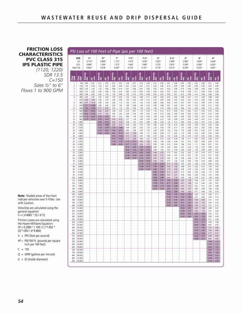
W A S T E W A T E R R E U S E A N D D R I P D I S P E R S A L G U I D E
54
W A S T E W A T E R R E U S E A N D D R I P D I S P E R S A L G U I D E
FRICTION LOSS CHARACTERISTICS
PVC CLASS 315 IPS PLASTIC PIPE
(1120, 1220)SDR 13.5
C=150Sizes ½" to 6"
Flows 1 to 900 GPM
Note:..Shaded.areas.of.the.chart.indicate.velocities.over.5.Ft/Sec..Use.with.Caution.
Velocities.are.calculated.using.the.general.equation:.V.=.(.0.4085.*.(Q./.d^2).
Friction.Losses.are.calculated.using.the.Hazen-Williams.Equation:.Hf.=.0.2083.*.(.100./.C.)^1.852.*.(Q^1.852./.d^4.866)
V. =. FPS.(feet.per.second)
Hf.=. PSI/100.Ft..(pounds.per.square.inch.per.100.feet)
C. =. 150
Q. =. GPM.(gallons.per.minute)
d. =. ID.(inside.diameter)
PSI Loss of 100 Feet of Pipe (psi per 100 feet)
Flow
GPM
Flow
GPH Velo
city
FPS
SIZE ½” ¾” 1” 1 ¼” 1 ½” 2” 2 ½” 3” 4” 6” I.D. 0.716'' 0.894'' 1.121'' 1.414'' 1.618'' 2.023'' 2.449'' 2.982'' 3.834'' 5.643'' O.D. 0.840'' 1.050'' 1.315'' 1.660'' 1.900'' 2.375'' 2.875'' 3.500'' 4.500'' 6.625'' Wall Thk 0.062'' 0.078'' 0.097'' 0.123'' 0.141'' 0.176'' 0.213'' 0.259'' 0.333'' 0.491''
PSI
Loss
Velo
city
FPS
PSI
Loss
Velo
city
FPS
PSI
Loss
Velo
city
FPS
PSI
Loss
Velo
city
FPS
PSI
Loss
Velo
city
FPS
PSI
Loss
Velo
city
FPS
PSI
Loss
Velo
city
FPS
PSI
Loss
Velo
city
FPS
PSI
Loss
Velo
city
FPS
PSI
Loss
1 60 0.80 0.22 0.51 0.07 0.33 0.02 0.20 0.01 0.16 0.00 0.10 0.00 0.07 0.00 0.05 0.00 0.03 0.00 0.01 0.00 2 120 1.59 0.78 1.02 0.27 0.65 0.09 0.41 0.03 0.31 0.01 0.20 0.00 0.14 0.00 0.09 0.00 0.06 0.00 0.03 0.00 3 180 2.39 1.65 1.53 0.56 0.98 0.19 0.61 0.06 0.47 0.03 0.30 0.01 0.20 0.00 0.14 0.00 0.08 0.00 0.04 0.00 4 240 3.19 2.82 2.04 0.96 1.30 0.32 0.82 0.10 0.62 0.05 0.40 0.02 0.27 0.01 0.18 0.00 0.11 0.00 0.05 0.00 5 300 3.98 4.26 2.56 1.45 1.63 0.48 1.02 0.16 0.78 0.08 0.50 0.03 0.34 0.01 0.23 0.00 0.14 0.00 0.06 0.00 6 360 4.78 5.97 3.07 2.03 1.95 0.67 1.23 0.22 0.94 0.11 0.60 0.04 0.41 0.02 0.28 0.01 0.17 0.00 0.08 0.00 7 420 5.58 7.95 3.58 2.70 2.28 0.90 1.43 0.29 1.09 0.15 0.70 0.05 0.48 0.02 0.32 0.01 0.19 0.00 0.09 0.00 8 480 6.37 10.18 4.09 3.45 2.60 1.15 1.63 0.37 1.25 0.19 0.80 0.06 0.54 0.03 0.37 0.01 0.22 0.00 0.10 0.00 9 540 7.17 12.66 4.60 4.30 2.93 1.43 1.84 0.46 1.40 0.24 0.90 0.08 0.61 0.03 0.41 0.01 0.25 0.00 0.12 0.00 10 600 7.97 15.38 5.11 5.22 3.25 1.74 2.04 0.56 1.56 0.29 1.00 0.10 0.68 0.04 0.46 0.01 0.28 0.00 0.13 0.00 11 660 8.77 18.35 5.62 6.23 3.58 2.07 2.25 0.67 1.72 0.35 1.10 0.12 0.75 0.05 0.51 0.02 0.31 0.01 0.14 0.00 12 720 9.56 21.56 6.13 7.32 3.90 2.43 2.45 0.79 1.87 0.41 1.20 0.14 0.82 0.05 0.55 0.02 0.33 0.01 0.15 0.00 14 840 11.16 28.69 7.16 9.74 4.55 3.24 2.86 1.05 2.18 0.54 1.40 0.18 0.95 0.07 0.64 0.03 0.39 0.01 0.18 0.00 16 960 12.75 36.73 8.18 12.47 5.20 4.15 3.27 1.34 2.50 0.70 1.60 0.23 1.09 0.09 0.74 0.04 0.44 0.01 0.21 0.00 18 1,080 9.20 15.51 5.85 5.16 3.68 1.67 2.81 0.86 1.80 0.29 1.23 0.12 0.83 0.04 0.50 0.01 0.23 0.00 20 1,200 10.22 18.85 6.50 6.27 4.09 2.03 3.12 1.05 2.00 0.35 1.36 0.14 0.92 0.05 0.56 0.02 0.26 0.00 22 1,320 11.24 22.49 7.15 7.48 4.49 2.42 3.43 1.25 2.20 0.42 1.50 0.17 1.01 0.06 0.61 0.02 0.28 0.00 24 1,440 12.27 26.42 7.80 8.79 4.90 2.84 3.74 1.47 2.40 0.50 1.63 0.20 1.10 0.08 0.67 0.02 0.31 0.00 26 1,560 13.29 30.65 8.45 10.19 5.31 3.29 4.06 1.71 2.60 0.58 1.77 0.23 1.19 0.09 0.72 0.03 0.33 0.00 28 1,680 9.10 11.69 5.72 3.78 4.37 1.96 2.79 0.66 1.91 0.26 1.29 0.10 0.78 0.03 0.36 0.00 30 1,800 9.75 13.28 6.13 4.29 4.68 2.23 2.99 0.75 2.04 0.30 1.38 0.11 0.83 0.03 0.38 0.01 35 2,100 11.38 17.67 7.15 5.71 5.46 2.96 3.49 1.00 2.38 0.39 1.61 0.15 0.97 0.04 0.45 0.01 40 2,400 13.00 22.63 8.17 7.31 6.24 3.79 3.99 1.28 2.72 0.50 1.84 0.19 1.11 0.06 0.51 0.01 45 2,700 9.19 9.09 7.02 4.72 4.49 1.59 3.06 0.63 2.07 0.24 1.25 0.07 0.58 0.01 50 3,000 10.22 11.05 7.80 5.74 4.99 1.93 3.41 0.76 2.30 0.29 1.39 0.09 0.64 0.01 55 3,300 11.24 13.19 8.58 6.84 5.49 2.31 3.75 0.91 2.53 0.35 1.53 0.10 0.71 0.02 60 3,600 12.26 15.49 9.36 8.04 5.99 2.71 4.09 1.07 2.76 0.41 1.67 0.12 0.77 0.02 65 3,900 13.28 17.97 10.14 9.33 6.49 3.14 4.43 1.24 2.99 0.48 1.81 0.14 0.83 0.02 70 4,200 10.92 10.70 6.99 3.61 4.77 1.42 3.22 0.55 1.95 0.16 0.90 0.02 75 4,500 11.70 12.16 7.49 4.10 5.11 1.62 3.45 0.62 2.08 0.18 0.96 0.03 80 4,800 12.48 13.70 7.99 4.62 5.45 1.82 3.68 0.70 2.22 0.21 1.03 0.03 85 5,100 13.26 15.33 8.48 5.17 5.79 2.04 3.90 0.78 2.36 0.23 1.09 0.04 90 5,400 8.98 5.75 6.13 2.27 4.13 0.87 2.50 0.26 1.15 0.04 95 5,700 9.48 6.35 6.47 2.51 4.36 0.96 2.64 0.28 1.22 0.04 100 6,000 9.98 6.98 6.81 2.76 4.59 1.06 2.78 0.31 1.28 0.05 110 6,600 10.98 8.33 7.49 3.29 5.05 1.26 3.06 0.37 1.41 0.06 120 7,200 11.98 9.79 8.17 3.86 5.51 1.48 3.33 0.44 1.54 0.07 130 7,800 12.98 11.35 8.85 4.48 5.97 1.72 3.61 0.51 1.67 0.08 140 8,400 13.97 13.02 9.54 5.14 6.43 1.97 3.89 0.58 1.80 0.09 150 9,000 10.22 5.84 6.89 2.24 4.17 0.66 1.92 0.10 160 9,600 10.90 6.58 7.35 2.52 4.45 0.74 2.05 0.11 170 10,200 11.58 7.36 7.81 2.82 4.72 0.83 2.18 0.13 180 10,800 12.26 8.18 8.27 3.14 5.00 0.92 2.31 0.14 190 11,400 12.94 9.05 8.73 3.47 5.28 1.02 2.44 0.16 200 12,000 13.62 9.95 9.19 3.82 5.56 1.12 2.57 0.17 225 13,500 10.34 4.75 6.25 1.40 2.89 0.21 250 15,000 11.48 5.77 6.95 1.70 3.21 0.26 275 16,500 12.63 6.88 7.64 2.03 3.53 0.31 300 18,000 13.78 8.09 8.34 2.38 3.85 0.36 325 19,500 9.03 2.76 4.17 0.42 350 21,000 9.73 3.17 4.49 0.48 375 22,500 10.42 3.60 4.81 0.55 400 24,000 11.12 4.06 5.13 0.62 425 25,500 11.81 4.54 5.45 0.69 450 27,000 12.51 5.04 5.77 0.77 475 28,500 13.20 5.57 6.09 0.85 500 30,000 13.89 6.13 6.41 0.93 550 33,000 7.06 1.12 600 36,000 7.70 1.31 650 39,000 8.34 1.52 700 42,000 8.98 1.74 750 45,000 9.62 1.98 800 48,000 10.26 2.23 850 51,000 10.90 2.50 900 54,000 11.55 2.78

W A S T E W A T E R R E U S E A N D D R I P D I S P E R S A L G U I D E
55
W A S T E W A T E R R E U S E A N D D R I P D I S P E R S A L G U I D E
FRICTION LOSS CHARACTERISTICS
PVC CLASS 200 IPS PLASTIC PIPE
(1120, 1220)SDR 21C=150
Sizes ¾" to 6"Flows 1 to 900 GPM
Note:..Shaded.areas.of.the.chart.indicate.velocities.over.5.Ft/Sec..Use.with.Caution.
Velocities.are.calculated.using.the.general.equation:.V.=.(.0.4085.*.(Q./.d^2).
Friction.Losses.are.calculated.using.the.Hazen-Williams.Equation:.Hf.=.0.2083.*.(.100./.C.)^1.852.*.(Q^1.852./.d^4.866)
V. =. FPS.(feet.per.second)
Hf.=. PSI/100.Ft..(pounds.per.square.inch.per.100.feet)
C. =. 150
Q. =. GPM.(gallons.per.minute)
d. =. ID.(inside.diameter)
PSI Loss of 100 Feet of Pipe (psi per 100 feet)
Flow
GPM
Flow
GPH Velo
city
FPS
SIZE ¾” 1” 1 ¼” 1 ½” 2” 2 ½” 3” 4” 6” I.D. 0.930'' 1.189'' 1.502'' 1.720'' 2.149'' 2.601'' 3.166'' 4.072'' 5.993'' O.D. 1.050'' 1.315'' 1.660'' 1.900'' 2.375'' 2.875'' 3.500'' 4.500'' 6.625'' Wall Thk 0.060'' 0.063'' 0.079'' 0.090'' 0.113'' 0.137'' 0.167'' 0.214'' 0.316''
PSI
Loss
Velo
city
FPS
PSI
Loss
Velo
city
FPS
PSI
Loss
Velo
city
FPS
PSI
Loss
Velo
city
FPS
PSI
Loss
Velo
city
FPS
PSI
Loss
Velo
city
FPS
PSI
Loss
Velo
city
FPS
PSI
Loss
Velo
city
FPS
PSI
Loss
1 60 0.47 0.06 0.29 0.02 0.18 0.01 0.14 0.00 0.09 0.00 0.06 0.00 0.04 0.00 0.02 0.00 0.01 0.00 2 120 0.94 0.22 0.58 0.07 0.36 0.02 0.28 0.01 0.18 0.00 0.12 0.00 0.08 0.00 0.05 0.00 0.02 0.00 3 180 1.42 0.46 0.87 0.14 0.54 0.04 0.41 0.02 0.27 0.01 0.18 0.00 0.12 0.00 0.07 0.00 0.03 0.00 4 240 1.89 0.79 1.16 0.24 0.72 0.08 0.55 0.04 0.35 0.01 0.24 0.01 0.16 0.00 0.10 0.00 0.05 0.00 5 300 2.36 1.19 1.44 0.36 0.91 0.12 0.69 0.06 0.44 0.02 0.30 0.01 0.20 0.00 0.12 0.00 0.06 0.00 6 360 2.83 1.67 1.73 0.51 1.09 0.16 0.83 0.08 0.53 0.03 0.36 0.01 0.24 0.00 0.15 0.00 0.07 0.00 7 420 3.31 2.23 2.02 0.67 1.27 0.22 0.97 0.11 0.62 0.04 0.42 0.01 0.29 0.01 0.17 0.00 0.08 0.00 8 480 3.78 2.85 2.31 0.86 1.45 0.28 1.10 0.14 0.71 0.05 0.48 0.02 0.33 0.01 0.20 0.00 0.09 0.00 9 540 4.25 3.55 2.60 1.07 1.63 0.34 1.24 0.18 0.80 0.06 0.54 0.02 0.37 0.01 0.22 0.00 0.10 0.00 10 600 4.72 4.31 2.89 1.30 1.81 0.42 1.38 0.22 0.88 0.07 0.60 0.03 0.41 0.01 0.25 0.00 0.11 0.00 11 660 5.20 5.14 3.18 1.56 1.99 0.50 1.52 0.26 0.97 0.09 0.66 0.03 0.45 0.01 0.27 0.00 0.13 0.00 12 720 5.67 6.04 3.47 1.83 2.17 0.59 1.66 0.30 1.06 0.10 0.72 0.04 0.49 0.02 0.30 0.00 0.14 0.00 14 840 6.61 8.04 4.05 2.43 2.54 0.78 1.93 0.40 1.24 0.14 0.85 0.05 0.57 0.02 0.34 0.01 0.16 0.00 16 960 7.56 10.29 4.62 3.11 2.90 1.00 2.21 0.52 1.42 0.17 0.97 0.07 0.65 0.03 0.39 0.01 0.18 0.00 18 1,080 8.50 12.80 5.20 3.87 3.26 1.24 2.49 0.64 1.59 0.22 1.09 0.09 0.73 0.03 0.44 0.01 0.20 0.00 20 1,200 9.45 15.56 5.78 4.71 3.62 1.51 2.76 0.78 1.77 0.26 1.21 0.10 0.82 0.04 0.49 0.01 0.23 0.00 22 1,320 10.39 18.56 6.36 5.62 3.98 1.80 3.04 0.93 1.95 0.32 1.33 0.12 0.90 0.05 0.54 0.01 0.25 0.00 24 1,440 11.34 21.81 6.93 6.60 4.35 2.12 3.31 1.09 2.12 0.37 1.45 0.15 0.98 0.06 0.59 0.02 0.27 0.00 26 1,560 12.28 25.29 7.51 7.65 4.71 2.45 3.59 1.27 2.30 0.43 1.57 0.17 1.06 0.07 0.64 0.02 0.30 0.00 28 1,680 13.22 29.01 8.09 8.78 5.07 2.82 3.87 1.46 2.48 0.49 1.69 0.19 1.14 0.07 0.69 0.02 0.32 0.00 30 1,800 8.67 9.97 5.43 3.20 4.14 1.65 2.65 0.56 1.81 0.22 1.22 0.08 0.74 0.02 0.34 0.00 35 2,100 10.11 13.27 6.34 4.26 4.83 2.20 3.10 0.74 2.11 0.29 1.43 0.11 0.86 0.03 0.40 0.01 40 2,400 11.56 16.99 7.24 5.45 5.52 2.82 3.54 0.95 2.42 0.38 1.63 0.14 0.99 0.04 0.45 0.01 45 2,700 13.00 21.13 8.15 6.78 6.21 3.51 3.98 1.19 2.72 0.47 1.83 0.18 1.11 0.05 0.51 0.01 50 3,000 9.05 8.24 6.90 4.26 4.42 1.44 3.02 0.57 2.04 0.22 1.23 0.06 0.57 0.01 55 3,300 9.96 9.83 7.59 5.08 4.86 1.72 3.32 0.68 2.24 0.26 1.35 0.08 0.63 0.01 60 3,600 10.86 11.55 8.28 5.97 5.31 2.02 3.62 0.80 2.45 0.31 1.48 0.09 0.68 0.01 65 3,900 11.77 13.39 8.98 6.93 5.75 2.34 3.92 0.93 2.65 0.36 1.60 0.10 0.74 0.02 70 4,200 12.68 15.36 9.67 7.95 6.19 2.69 4.23 1.06 2.85 0.41 1.72 0.12 0.80 0.02 75 4,500 13.58 17.46 10.36 9.03 6.63 3.05 4.53 1.21 3.06 0.46 1.85 0.14 0.85 0.02 80 4,800 11.05 10.17 7.08 3.44 4.83 1.36 3.26 0.52 1.97 0.15 0.91 0.02 85 5,100 11.74 11.38 7.52 3.85 5.13 1.52 3.46 0.58 2.09 0.17 0.97 0.03 90 5,400 12.43 12.65 7.96 4.28 5.43 1.69 3.67 0.65 2.22 0.19 1.02 0.03 95 5,700 13.12 13.99 8.40 4.73 5.74 1.87 3.87 0.72 2.34 0.21 1.08 0.03 100 6,000 13.81 15.38 8.85 5.20 6.04 2.06 4.08 0.79 2.46 0.23 1.14 0.04 110 6,600 9.73 6.21 6.64 2.45 4.48 0.94 2.71 0.28 1.25 0.04 120 7,200 10.61 7.30 7.25 2.88 4.89 1.11 2.96 0.33 1.36 0.05 130 7,800 11.50 8.46 7.85 3.34 5.30 1.28 3.20 0.38 1.48 0.06 140 8,400 12.38 9.71 8.45 3.83 5.71 1.47 3.45 0.43 1.59 0.07 150 9,000 13.27 11.03 9.06 4.36 6.11 1.67 3.70 0.49 1.71 0.08 160 9,600 9.66 4.91 6.52 1.89 3.94 0.55 1.82 0.08 170 10,200 10.27 5.49 6.93 2.11 4.19 0.62 1.93 0.09 180 10,800 10.87 6.11 7.34 2.35 4.43 0.69 2.05 0.11 190 11,400 11.47 6.75 7.74 2.59 4.68 0.76 2.16 0.12 200 12,000 12.08 7.42 8.15 2.85 4.93 0.84 2.27 0.13 225 13,500 13.59 9.23 9.17 3.55 5.54 1.04 2.56 0.16 250 15,000 10.19 4.31 6.16 1.27 2.84 0.19 275 16,500 11.21 5.14 6.77 1.51 3.13 0.23 300 18,000 12.23 6.04 7.39 1.78 3.41 0.27 325 19,500 13.25 7.01 8.01 2.06 3.70 0.31 350 21,000 8.62 2.36 3.98 0.36 375 22,500 9.24 2.68 4.27 0.41 400 24,000 9.85 3.03 4.55 0.46 425 25,500 10.47 3.38 4.83 0.52 450 27,000 11.09 3.76 5.12 0.57 475 28,500 11.70 4.16 5.40 0.63 500 30,000 12.32 4.57 5.69 0.70 550 33,000 13.55 5.46 6.26 0.83 600 36,000 6.82 0.98 650 39,000 7.39 1.13 700 42,000 7.96 1.30 750 45,000 8.53 1.48 800 48,000 9.10 1.67 850 51,000 9.67 1.86 900 54,000 10.24 2.07

W A S T E W A T E R R E U S E A N D D R I P D I S P E R S A L G U I D E
56
W A S T E W A T E R R E U S E A N D D R I P D I S P E R S A L G U I D E
PSI Loss of 100 Feet of Pipe (psi per 100 feet)
Flow
GPM
Flow
GPH Velo
city
FPS
SIZE 1” 1 ¼” 1 ½” 2” 2 ½” 3” 4” 6” I.D. 1.195'' 1.532'' 1.754'' 2.193'' 2.655'' 3.230'' 4.154'' 6.115'' O.D. 1.315'' 1.660'' 1.900'' 2.375'' 2.875'' 3.500'' 4.500'' 6.625'' Wall Thk 0.060'' 0.064'' 0.073'' 0.091'' 0.110'' 0.135'' 0.173'' 0.255''
PSI
Loss
Velo
city
FPS
PSI
Loss
Velo
city
FPS
PSI
Loss
Velo
city
FPS
PSI
Loss
Velo
city
FPS
PSI
Loss
Velo
city
FPS
PSI
Loss
Velo
city
FPS
PSI
Loss
Velo
city
FPS
PSI
Loss
1 60 0.29 0.02 0.17 0.01 0.13 0.00 0.08 0.00 0.06 0.00 0.04 0.00 0.02 0.00 0.01 0.00 2 120 0.57 0.06 0.35 0.02 0.27 0.01 0.17 0.00 0.12 0.00 0.08 0.00 0.05 0.00 0.02 0.00 3 180 0.86 0.14 0.52 0.04 0.40 0.02 0.25 0.01 0.17 0.00 0.12 0.00 0.07 0.00 0.03 0.00 4 240 1.14 0.23 0.70 0.07 0.53 0.04 0.34 0.01 0.23 0.00 0.16 0.00 0.09 0.00 0.04 0.00 5 300 1.43 0.35 0.87 0.11 0.66 0.05 0.42 0.02 0.29 0.01 0.20 0.00 0.12 0.00 0.05 0.00 6 360 1.72 0.49 1.04 0.15 0.80 0.08 0.51 0.03 0.35 0.01 0.23 0.00 0.14 0.00 0.07 0.00 7 420 2.00 0.66 1.22 0.20 0.93 0.10 0.59 0.03 0.41 0.01 0.27 0.01 0.17 0.00 0.08 0.00 8 480 2.29 0.84 1.39 0.25 1.06 0.13 0.68 0.04 0.46 0.02 0.31 0.01 0.19 0.00 0.09 0.00 9 540 2.57 1.05 1.57 0.31 1.20 0.16 0.76 0.05 0.52 0.02 0.35 0.01 0.21 0.00 0.10 0.00 10 600 2.86 1.27 1.74 0.38 1.33 0.20 0.85 0.07 0.58 0.03 0.39 0.01 0.24 0.00 0.11 0.00 11 660 3.15 1.52 1.91 0.45 1.46 0.23 0.93 0.08 0.64 0.03 0.43 0.01 0.26 0.00 0.12 0.00 12 720 3.43 1.78 2.09 0.53 1.59 0.28 1.02 0.09 0.70 0.04 0.47 0.01 0.28 0.00 0.13 0.00 14 840 4.00 2.37 2.44 0.71 1.86 0.37 1.19 0.12 0.81 0.05 0.55 0.02 0.33 0.01 0.15 0.00 16 960 4.58 3.04 2.78 0.91 2.12 0.47 1.36 0.16 0.93 0.06 0.63 0.02 0.38 0.01 0.17 0.00 18 1,080 5.15 3.78 3.13 1.13 2.39 0.58 1.53 0.20 1.04 0.08 0.70 0.03 0.43 0.01 0.20 0.00 20 1,200 5.72 4.59 3.48 1.37 2.66 0.71 1.70 0.24 1.16 0.09 0.78 0.04 0.47 0.01 0.22 0.00 22 1,320 6.29 5.48 3.83 1.64 2.92 0.85 1.87 0.29 1.27 0.11 0.86 0.04 0.52 0.01 0.24 0.00 24 1,440 6.87 6.44 4.18 1.92 3.19 0.99 2.04 0.34 1.39 0.13 0.94 0.05 0.57 0.01 0.26 0.00 26 1,560 7.44 7.47 4.53 2.23 3.45 1.15 2.21 0.39 1.51 0.15 1.02 0.06 0.62 0.02 0.28 0.00 28 1,680 8.01 8.56 4.87 2.56 3.72 1.32 2.38 0.45 1.62 0.18 1.10 0.07 0.66 0.02 0.31 0.00 30 1,800 8.58 9.73 5.22 2.91 3.98 1.50 2.55 0.51 1.74 0.20 1.17 0.08 0.71 0.02 0.33 0.00 35 2,100 10.01 12.95 6.09 3.87 4.65 2.00 2.97 0.67 2.03 0.27 1.37 0.10 0.83 0.03 0.38 0.00 40 2,400 11.44 16.58 6.96 4.95 5.31 2.56 3.40 0.86 2.32 0.34 1.57 0.13 0.95 0.04 0.44 0.01 45 2,700 12.87 20.62 7.83 6.16 5.98 3.19 3.82 1.07 2.61 0.42 1.76 0.16 1.07 0.05 0.49 0.01 50 3,000 8.70 7.48 6.64 3.87 4.25 1.31 2.90 0.52 1.96 0.20 1.18 0.06 0.55 0.01 55 3,300 9.57 8.93 7.30 4.62 4.67 1.56 3.19 0.61 2.15 0.24 1.30 0.07 0.60 0.01 60 3,600 10.44 10.49 7.97 5.43 5.10 1.83 3.48 0.72 2.35 0.28 1.42 0.08 0.66 0.01 65 3,900 11.31 12.16 8.63 6.30 5.52 2.12 3.77 0.84 2.55 0.32 1.54 0.09 0.71 0.01 70 4,200 12.18 13.95 9.29 7.22 5.95 2.44 4.06 0.96 2.74 0.37 1.66 0.11 0.76 0.02 75 4,500 13.05 15.86 9.96 8.21 6.37 2.77 4.35 1.09 2.94 0.42 1.78 0.12 0.82 0.02 80 4,800 13.92 17.87 10.62 9.25 6.80 3.12 4.64 1.23 3.13 0.47 1.89 0.14 0.87 0.02 85 5,100 11.29 10.35 7.22 3.49 4.93 1.38 3.33 0.53 2.01 0.16 0.93 0.02 90 5,400 11.95 11.50 7.64 3.88 5.22 1.53 3.52 0.59 2.13 0.17 0.98 0.03 95 5,700 12.61 12.72 8.07 4.29 5.51 1.69 3.72 0.65 2.25 0.19 1.04 0.03 100 6,000 13.28 13.98 8.49 4.72 5.80 1.86 3.92 0.72 2.37 0.21 1.09 0.03 110 6,600 9.34 5.63 6.37 2.22 4.31 0.85 2.60 0.25 1.20 0.04 120 7,200 10.19 6.61 6.95 2.61 4.70 1.00 2.84 0.30 1.31 0.04 130 7,800 11.04 7.67 7.53 3.02 5.09 1.16 3.08 0.34 1.42 0.05 140 8,400 11.89 8.79 8.11 3.47 5.48 1.34 3.31 0.39 1.53 0.06 150 9,000 12.74 9.99 8.69 3.94 5.87 1.52 3.55 0.45 1.64 0.07 160 9,600 13.59 11.26 9.27 4.44 6.26 1.71 3.79 0.50 1.75 0.08 170 10,200 9.85 4.97 6.66 1.91 4.02 0.56 1.86 0.09 180 10,800 10.43 5.52 7.05 2.13 4.26 0.63 1.97 0.10 190 11,400 11.01 6.11 7.44 2.35 4.50 0.69 2.08 0.11 200 12,000 11.59 6.72 7.83 2.59 4.73 0.76 2.18 0.12 225 13,500 13.04 8.35 8.81 3.22 5.33 0.95 2.46 0.14 250 15,000 9.79 3.91 5.92 1.15 2.73 0.18 275 16,500 10.77 4.67 6.51 1.37 3.00 0.21 300 18,000 11.75 5.48 7.10 1.61 3.28 0.25 325 19,500 12.73 6.36 7.69 1.87 3.55 0.28 350 21,000 13.70 7.29 8.29 2.14 3.82 0.33 375 22,500 8.88 2.44 4.10 0.37 400 24,000 9.47 2.75 4.37 0.42 425 25,500 10.06 3.07 4.64 0.47 450 27,000 10.65 3.41 4.92 0.52 475 28,500 11.24 3.77 5.19 0.58 500 30,000 11.84 4.15 5.46 0.63 550 33,000 13.02 4.95 6.01 0.75 600 36,000 6.55 0.89 650 39,000 7.10 1.03 700 42,000 7.65 1.18 750 45,000 8.19 1.34 800 48,000 8.74 1.51 850 51,000 9.29 1.69 900 54,000 9.83 1.88
FRICTION LOSS CHARACTERISTICS
PVC CLASS 160 IPS PLASTIC PIPE
(1120, 1220)SDR 26C=150
Sizes 1" to 6"Flows 1 to 600 GPM
Note:..Shaded.areas.of.the.chart.indicate.velocities.over.5.Ft/Sec..Use.with.Caution.
Velocities.are.calculated.using.the.general.equation:.V.=.(.0.4085.*.(Q./.d^2).
Friction.Losses.are.calculated.using.the.Hazen-Williams.Equation:.Hf.=.0.2083.*.(.100./.C.)^1.852.*.(Q^1.852./.d^4.866)
V. =. FPS.(feet.per.second)
Hf.=. PSI/100.Ft..(pounds.per.square.inch.per.100.feet)
C. =. 150
Q. =. GPM.(gallons.per.minute)
d. =. ID.(inside.diameter)

W A S T E W A T E R R E U S E A N D D R I P D I S P E R S A L G U I D E
57
W A S T E W A T E R R E U S E A N D D R I P D I S P E R S A L G U I D E
FRICTION LOSS CHARACTERISTICS
PVC CLASS 125 IPS PLASTIC PIPE
(1120, 1220)SDR 32.5
C=150Sizes 1" to 6"
Flows 1 to 600 GPM
Note:..Shaded.areas.of.the.chart.indicate.velocities.over.5.Ft/Sec..Use.with.Caution.
Velocities.are.calculated.using.the.general.equation:.V.=.(.0.4085.*.(Q./.d^2).
Friction.Losses.are.calculated.using.the.Hazen-Williams.Equation:.Hf.=.0.2083.*.(.100./.C.)^1.852.*.(Q^1.852./.d^4.866)
V. =. FPS.(feet.per.second)
Hf.=. PSI/100.Ft..(pounds.per.square.inch.per.100.feet)
C. =. 150
Q. =. GPM.(gallons.per.minute)
d. =. ID.(inside.diameter)
PSI Loss of 100 Feet of Pipe (psi per 100 feet)
Flow
GPM
Flow
GPH Velo
city
FPS
SIZE 1” 1 ¼” 1 ½” 2” 2 ½” 3” 4” 6” I.D. 1.211'' 1.548'' 1.784'' 2.229'' 2.699'' 3.284'' 4.224'' 6.217'' O.D. 1.315'' 1.660'' 1.900'' 2.375'' 2.875'' 3.500'' 4.500'' 6.625'' Wall Thk 0.052'' 0.056'' 0.058'' 0.073'' 0.088'' 0.108'' 0.138'' 0.204''
PSI
Loss
Velo
city
FPS
PSI
Loss
Velo
city
FPS
PSI
Loss
Velo
city
FPS
PSI
Loss
Velo
city
FPS
PSI
Loss
Velo
city
FPS
PSI
Loss
Velo
city
FPS
PSI
Loss
Velo
city
FPS
PSI
Loss
1 60 0.28 0.02 0.17 0.01 0.13 0.00 0.08 0.00 0.06 0.00 0.04 0.00 0.02 0.00 0.01 0.00 2 120 0.56 0.06 0.34 0.02 0.26 0.01 0.16 0.00 0.11 0.00 0.08 0.00 0.05 0.00 0.02 0.00 3 180 0.84 0.13 0.51 0.04 0.39 0.02 0.25 0.01 0.17 0.00 0.11 0.00 0.07 0.00 0.03 0.00 4 240 1.11 0.22 0.68 0.07 0.51 0.03 0.33 0.01 0.22 0.00 0.15 0.00 0.09 0.00 0.04 0.00 5 300 1.39 0.33 0.85 0.10 0.64 0.05 0.41 0.02 0.28 0.01 0.19 0.00 0.11 0.00 0.05 0.00 6 360 1.67 0.46 1.02 0.14 0.77 0.07 0.49 0.02 0.34 0.01 0.23 0.00 0.14 0.00 0.06 0.00 7 420 1.95 0.62 1.19 0.19 0.90 0.09 0.58 0.03 0.39 0.01 0.27 0.00 0.16 0.00 0.07 0.00 8 480 2.23 0.79 1.36 0.24 1.03 0.12 0.66 0.04 0.45 0.02 0.30 0.01 0.18 0.00 0.08 0.00 9 540 2.51 0.98 1.53 0.30 1.16 0.15 0.74 0.05 0.50 0.02 0.34 0.01 0.21 0.00 0.10 0.00 10 600 2.79 1.19 1.70 0.36 1.28 0.18 0.82 0.06 0.56 0.02 0.38 0.01 0.23 0.00 0.11 0.00 11 660 3.06 1.42 1.88 0.43 1.41 0.22 0.90 0.07 0.62 0.03 0.42 0.01 0.25 0.00 0.12 0.00 12 720 3.34 1.67 2.05 0.51 1.54 0.25 0.99 0.09 0.67 0.03 0.45 0.01 0.27 0.00 0.13 0.00 14 840 3.90 2.22 2.39 0.67 1.80 0.34 1.15 0.11 0.79 0.05 0.53 0.02 0.32 0.01 0.15 0.00 16 960 4.46 2.85 2.73 0.86 2.05 0.43 1.32 0.15 0.90 0.06 0.61 0.02 0.37 0.01 0.17 0.00 18 1,080 5.01 3.54 3.07 1.07 2.31 0.54 1.48 0.18 1.01 0.07 0.68 0.03 0.41 0.01 0.19 0.00 20 1,200 5.57 4.31 3.41 1.30 2.57 0.65 1.64 0.22 1.12 0.09 0.76 0.03 0.46 0.01 0.21 0.00 22 1,320 6.13 5.14 3.75 1.56 2.82 0.78 1.81 0.26 1.23 0.10 0.83 0.04 0.50 0.01 0.23 0.00 24 1,440 6.69 6.03 4.09 1.83 3.08 0.92 1.97 0.31 1.35 0.12 0.91 0.05 0.55 0.01 0.25 0.00 26 1,560 7.24 7.00 4.43 2.12 3.34 1.06 2.14 0.36 1.46 0.14 0.98 0.05 0.60 0.02 0.27 0.00 28 1,680 7.80 8.03 4.77 2.43 3.59 1.22 2.30 0.41 1.57 0.16 1.06 0.06 0.64 0.02 0.30 0.00 30 1,800 8.36 9.12 5.11 2.76 3.85 1.38 2.47 0.47 1.68 0.18 1.14 0.07 0.69 0.02 0.32 0.00 35 2,100 9.75 12.14 5.97 3.67 4.49 1.84 2.88 0.62 1.96 0.25 1.33 0.09 0.80 0.03 0.37 0.00 40 2,400 11.14 15.54 6.82 4.71 5.13 2.36 3.29 0.80 2.24 0.31 1.52 0.12 0.92 0.04 0.42 0.01 45 2,700 12.53 19.33 7.67 5.85 5.78 2.93 3.70 0.99 2.52 0.39 1.70 0.15 1.03 0.04 0.48 0.01 50 3,000 13.93 23.49 8.52 7.11 6.42 3.57 4.11 1.21 2.80 0.48 1.89 0.18 1.14 0.05 0.53 0.01 55 3,300 9.38 8.49 7.06 4.26 4.52 1.44 3.08 0.57 2.08 0.22 1.26 0.06 0.58 0.01 60 3,600 10.23 9.97 7.70 5.00 4.93 1.69 3.36 0.67 2.27 0.26 1.37 0.08 0.63 0.01 65 3,900 11.08 11.57 8.34 5.80 5.34 1.96 3.65 0.77 2.46 0.30 1.49 0.09 0.69 0.01 70 4,200 11.93 13.27 8.98 6.65 5.76 2.25 3.93 0.89 2.65 0.34 1.60 0.10 0.74 0.02 75 4,500 12.79 15.07 9.63 7.56 6.17 2.56 4.21 1.01 2.84 0.39 1.72 0.11 0.79 0.02 80 4,800 13.64 16.99 10.27 8.52 6.58 2.88 4.49 1.14 3.03 0.44 1.83 0.13 0.85 0.02 85 5,100 10.91 9.53 6.99 3.22 4.77 1.27 3.22 0.49 1.95 0.14 0.90 0.02 90 5,400 11.55 10.59 7.40 3.58 5.05 1.41 3.41 0.54 2.06 0.16 0.95 0.02 95 5,700 12.19 11.71 7.81 3.96 5.33 1.56 3.60 0.60 2.18 0.18 1.00 0.03 100 6,000 12.84 12.88 8.22 4.36 5.61 1.72 3.79 0.66 2.29 0.19 1.06 0.03 110 6,600 9.04 5.20 6.17 2.05 4.17 0.79 2.52 0.23 1.16 0.04 120 7,200 9.87 6.11 6.73 2.41 4.55 0.93 2.75 0.27 1.27 0.04 130 7,800 10.69 7.08 7.29 2.79 4.92 1.07 2.98 0.32 1.37 0.05 140 8,400 11.51 8.12 7.85 3.20 5.30 1.23 3.21 0.36 1.48 0.06 150 9,000 12.33 9.23 8.41 3.64 5.68 1.40 3.43 0.41 1.59 0.06 160 9,600 13.16 10.40 8.97 4.10 6.06 1.58 3.66 0.46 1.69 0.07 170 10,200 13.98 11.64 9.53 4.59 6.44 1.77 3.89 0.52 1.80 0.08 180 10,800 10.09 5.10 6.82 1.96 4.12 0.58 1.90 0.09 190 11,400 10.65 5.64 7.20 2.17 4.35 0.64 2.01 0.10 200 12,000 11.22 6.20 7.58 2.39 4.58 0.70 2.11 0.11 225 13,500 12.62 7.71 8.52 2.97 5.15 0.87 2.38 0.13 250 15,000 9.47 3.61 5.72 1.06 2.64 0.16 275 16,500 10.42 4.30 6.30 1.26 2.91 0.19 300 18,000 11.36 5.06 6.87 1.49 3.17 0.23 325 19,500 12.31 5.86 7.44 1.72 3.43 0.26 350 21,000 13.26 6.73 8.01 1.98 3.70 0.30 375 22,500 8.59 2.25 3.96 0.34 400 24,000 9.16 2.53 4.23 0.39 425 25,500 9.73 2.83 4.49 0.43 450 27,000 10.30 3.15 4.76 0.48 475 28,500 10.88 3.48 5.02 0.53 500 30,000 11.45 3.83 5.28 0.58 550 33,000 12.59 4.56 5.81 0.70 600 36,000 13.74 5.36 6.34 0.82 650 39,000 6.87 0.95 700 42,000 7.40 1.09 750 45,000 7.93 1.24 800 48,000 8.46 1.39 850 51,000 8.98 1.56 900 54,000 9.51 1.73

W A S T E W A T E R R E U S E A N D D R I P D I S P E R S A L G U I D E
58
W A S T E W A T E R R E U S E A N D D R I P D I S P E R S A L G U I D E
Note:..Shaded.areas.of.the.chart.indicate.velocities.over.5.Ft/Sec..Use.with.Caution.
Velocities.are.calculated.using.the.general.equation:.V.=.(.0.4085.*.(Q./.d^2).
Friction.Losses.are.calculated.using.the.Hazen-Williams.Equation:.Hf.=.0.2083.*.(.100./.C.)^1.852.*.(Q^1.852./.d^4.866)
V. =. FPS.(feet.per.second)
Hf.=. PSI/100.Ft..(pounds.per.square.inch.per.100.feet)
C. =. 150
Q. =. GPM.(gallons.per.minute)
d. =. ID.(inside.diameter)
PSI Loss of 100 Feet of Pipe (psi per 100 feet)
Flow
GPM
Flow
GPH Velo
city
FPS
SIZE ½” ¾” 1” 1 ¼” 1 ½” 2” 2 ½” 3” 4” 6” I.D. 0.622'' 0.824'' 1.049'' 1.380'' 1.610'' 2.067'' 2.469'' 3.068'' 4.026'' 6.065''
PSI
Loss
Velo
city
FPS
PSI
Loss
Velo
city
FPS
PSI
Loss
Velo
city
FPS
PSI
Loss
Velo
city
FPS
PSI
Loss
Velo
city
FPS
PSI
Loss
Velo
city
FPS
PSI
Loss
Velo
city
FPS
PSI
Loss
Velo
city
FPS
PSI
Loss
Velo
city
FPS
PSI
Loss
1 60 1.06 0.49 0.60 0.12 0.37 0.04 0.21 0.01 0.16 0.00 0.10 0.00 0.07 0.00 0.04 0.00 0.03 0.00 0.01 0.00 2 120 2.11 1.76 1.20 0.45 0.74 0.14 0.43 0.04 0.32 0.02 0.19 0.01 0.13 0.00 0.09 0.00 0.05 0.00 0.02 0.00 3 180 3.17 3.73 1.80 0.95 1.11 0.29 0.64 0.08 0.47 0.04 0.29 0.01 0.20 0.00 0.13 0.00 0.08 0.00 0.03 0.00 4 240 4.22 6.35 2.41 1.62 1.48 0.50 0.86 0.13 0.63 0.06 0.38 0.02 0.27 0.01 0.17 0.00 0.10 0.00 0.04 0.00 5 300 5.28 9.60 3.01 2.44 1.86 0.76 1.07 0.20 0.79 0.09 0.48 0.03 0.34 0.01 0.22 0.00 0.13 0.00 0.06 0.00 6 360 6.34 13.46 3.61 3.43 2.23 1.06 1.29 0.28 0.95 0.13 0.57 0.04 0.40 0.02 0.26 0.01 0.15 0.00 0.07 0.00 7 420 7.39 17.91 4.21 4.56 2.60 1.41 1.50 0.37 1.10 0.18 0.67 0.05 0.47 0.02 0.30 0.01 0.18 0.00 0.08 0.00 8 480 8.45 22.93 4.81 5.84 2.97 1.80 1.72 0.47 1.26 0.22 0.76 0.07 0.54 0.03 0.35 0.01 0.20 0.00 0.09 0.00 9 540 9.50 28.52 5.41 7.26 3.34 2.24 1.93 0.59 1.42 0.28 0.86 0.08 0.60 0.03 0.39 0.01 0.23 0.00 0.10 0.00 10 600 10.56 34.67 6.02 8.82 3.71 2.73 2.15 0.72 1.58 0.34 0.96 0.10 0.67 0.04 0.43 0.01 0.25 0.00 0.11 0.00 11 660 11.61 41.36 6.62 10.53 4.08 3.25 2.36 0.86 1.73 0.40 1.05 0.12 0.74 0.05 0.48 0.02 0.28 0.00 0.12 0.00 12 720 12.67 48.60 7.22 12.37 4.45 3.82 2.57 1.01 1.89 0.48 1.15 0.14 0.80 0.06 0.52 0.02 0.30 0.01 0.13 0.00 14 840 8.42 16.45 5.20 5.08 3.00 1.34 2.21 0.63 1.34 0.19 0.94 0.08 0.61 0.03 0.35 0.01 0.16 0.00 16 960 9.63 21.07 5.94 6.51 3.43 1.71 2.52 0.81 1.53 0.24 1.07 0.10 0.69 0.04 0.40 0.01 0.18 0.00 18 1,080 10.83 26.21 6.68 8.10 3.86 2.13 2.84 1.01 1.72 0.30 1.21 0.13 0.78 0.04 0.45 0.01 0.20 0.00 20 1,200 12.03 31.85 7.42 9.84 4.29 2.59 3.15 1.22 1.91 0.36 1.34 0.15 0.87 0.05 0.50 0.01 0.22 0.00 22 1,320 13.24 38.00 8.17 11.74 4.72 3.09 3.47 1.46 2.10 0.43 1.47 0.18 0.95 0.06 0.55 0.02 0.24 0.00 24 1,440 8.91 13.79 5.15 3.63 3.78 1.72 2.29 0.51 1.61 0.21 1.04 0.07 0.60 0.02 0.27 0.00 26 1,560 9.65 16.00 5.58 4.21 4.10 1.99 2.49 0.59 1.74 0.25 1.13 0.09 0.66 0.02 0.29 0.00 28 1,680 10.39 18.35 6.01 4.83 4.41 2.28 2.68 0.68 1.88 0.28 1.22 0.10 0.71 0.03 0.31 0.00 30 1,800 11.14 20.85 6.44 5.49 4.73 2.59 2.87 0.77 2.01 0.32 1.30 0.11 0.76 0.03 0.33 0.00 35 2,100 12.99 27.74 7.51 7.30 5.52 3.45 3.35 1.02 2.35 0.43 1.52 0.15 0.88 0.04 0.39 0.01 40 2,400 8.58 9.35 6.30 4.42 3.82 1.31 2.68 0.55 1.74 0.19 1.01 0.05 0.44 0.01 45 2,700 9.65 11.63 7.09 5.49 4.30 1.63 3.02 0.69 1.95 0.24 1.13 0.06 0.50 0.01 50 3,000 10.73 14.14 7.88 6.68 4.78 1.98 3.35 0.83 2.17 0.29 1.26 0.08 0.56 0.01 55 3,300 11.80 16.87 8.67 7.97 5.26 2.36 3.69 0.99 2.39 0.35 1.39 0.09 0.61 0.01 60 3,600 12.87 19.82 9.46 9.36 5.74 2.77 4.02 1.17 2.60 0.41 1.51 0.11 0.67 0.01 65 3,900 13.94 22.98 10.24 10.86 6.21 3.22 4.36 1.36 2.82 0.47 1.64 0.13 0.72 0.02 70 4,200 11.03 12.45 6.69 3.69 4.69 1.55 3.04 0.54 1.76 0.14 0.78 0.02 75 4,500 11.82 14.15 7.17 4.19 5.03 1.77 3.25 0.61 1.89 0.16 0.83 0.02 80 4,800 12.61 15.95 7.65 4.73 5.36 1.99 3.47 0.69 2.02 0.18 0.89 0.03 85 5,100 13.40 17.84 8.13 5.29 5.70 2.23 3.69 0.77 2.14 0.21 0.94 0.03 90 5,400 8.61 5.88 6.03 2.48 3.91 0.86 2.27 0.23 1.00 0.03 95 5,700 9.08 6.50 6.37 2.74 4.12 0.95 2.39 0.25 1.06 0.03 100 6,000 9.56 7.15 6.70 3.01 4.34 1.05 2.52 0.28 1.11 0.04 110 6,600 10.52 8.53 7.37 3.59 4.77 1.25 2.77 0.33 1.22 0.05 120 7,200 11.47 10.02 8.04 4.22 5.21 1.47 3.02 0.39 1.33 0.05 130 7,800 12.43 11.62 8.71 4.89 5.64 1.70 3.28 0.45 1.44 0.06 140 8,400 13.39 13.33 9.38 5.61 6.08 1.95 3.53 0.52 1.55 0.07 150 9,000 10.05 6.38 6.51 2.22 3.78 0.59 1.67 0.08 160 9,600 10.72 7.19 6.94 2.50 4.03 0.67 1.78 0.09 170 10,200 11.39 8.04 7.38 2.79 4.28 0.74 1.89 0.10 180 10,800 12.06 8.94 7.81 3.11 4.54 0.83 2.00 0.11 190 11,400 12.73 9.88 8.25 3.43 4.79 0.92 2.11 0.12 200 12,000 13.40 10.87 8.68 3.78 5.04 1.01 2.22 0.14 225 13,500 9.76 4.70 5.67 1.25 2.50 0.17 250 15,000 10.85 5.71 6.30 1.52 2.78 0.21 275 16,500 11.93 6.81 6.93 1.81 3.05 0.25 300 18,000 13.02 8.00 7.56 2.13 3.33 0.29 325 19,500 8.19 2.47 3.61 0.34 350 21,000 8.82 2.84 3.89 0.39 375 22,500 9.45 3.22 4.16 0.44 400 24,000 10.08 3.63 4.44 0.49 425 25,500 10.71 4.06 4.72 0.55 450 27,000 11.34 4.52 5.00 0.62 475 28,500 11.97 4.99 5.28 0.68 500 30,000 12.60 5.49 5.55 0.75 550 33,000 13.86 6.55 6.11 0.89 600 36,000 6.66 1.05 650 39,000 7.22 1.22 700 42,000 7.77 1.39 750 45,000 8.33 1.58 800 48,000 8.88 1.79 850 51,000 9.44 2.00 900 54,000 9.99 2.22
FRICTION LOSS CHARACTERISTICS
POLYETHYLENE (PE) SDR PRESSURE
RATED PIPE (2306, 3206, 3306)
SDR 7, 9, 11.5, 15C=150
Sizes ½" to 6"Flows 1 to 900 GPM

W A S T E W A T E R R E U S E A N D D R I P D I S P E R S A L G U I D E
59
W A S T E W A T E R R E U S E A N D D R I P D I S P E R S A L G U I D E
FRICTION LOSS CHARACTERISTICS
SCHEDULE 40 STANDARD STEEL
C=100Sizes ½" to 6"
Flows 1 to 900 GPM
Note:..Shaded.areas.of.the.chart.indicate.velocities.over.5.Ft/Sec..Use.with.Caution.
Velocities.are.calculated.using.the.general.equation:.V.=.(.0.4085.*.(Q./.d^2).
Friction.Losses.are.calculated.using.the.Hazen-Williams.Equation:.Hf.=.0.2083.*.(.100./.C.)^1.852.*.(Q^1.852./.d^4.866)
V. =. FPS.(feet.per.second)
Hf.=. PSI/100.Ft..(pounds.per.square.inch.per.100.feet)
C. =. 100
Q. =. GPM.(gallons.per.minute)
d. =. ID.(inside.diameter)
PSI Loss of 100 Feet of Pipe (psi per 100 feet)
Flow
GPM
Flow
GPH Velo
city
FPS
SIZE ½” ¾” 1” 1 ¼” 1 ½” 2” 2 ½” 3” 4” 6” I.D. 0.622'' 0.824'' 1.049'' 1.380'' 1.610'' 2.067'' 2.469'' 3.068'' 4.026'' 6.065'' O.D. 0.840'' 1.050'' 1.315'' 1.660'' 1.900'' 2.375'' 2.875'' 3.500'' 4.500'' 6.625'' Wall Thk 0.109'' 0.113'' 0.133'' 0.140'' 0.145'' 0.154'' 0.203'' 0.216'' 0.237'' 0.280''
PSI
Loss
Velo
city
FPS
PSI
Loss
Velo
city
FPS
PSI
Loss
Velo
city
FPS
PSI
Loss
Velo
city
FPS
PSI
Loss
Velo
city
FPS
PSI
Loss
Velo
city
FPS
PSI
Loss
Velo
city
FPS
PSI
Loss
Velo
city
FPS
PSI
Loss
Velo
city
FPS
PSI
Loss
1 60 1.06 0.91 0.60 0.23 0.37 0.07 0.21 0.02 0.16 0.01 0.10 0.00 0.07 0.00 0.04 0.00 0.03 0.00 0.01 0.00 2 120 2.11 3.28 1.20 0.84 0.74 0.26 0.43 0.07 0.32 0.03 0.19 0.01 0.13 0.00 0.09 0.00 0.05 0.00 0.02 0.00 3 180 3.17 6.95 1.80 1.77 1.11 0.55 0.64 0.14 0.47 0.07 0.29 0.02 0.20 0.01 0.13 0.00 0.08 0.00 0.03 0.00 4 240 4.22 11.85 2.41 3.02 1.48 0.93 0.86 0.25 0.63 0.12 0.38 0.03 0.27 0.01 0.17 0.01 0.10 0.00 0.04 0.00 5 300 5.28 17.91 3.01 4.56 1.86 1.41 1.07 0.37 0.79 0.18 0.48 0.05 0.34 0.02 0.22 0.01 0.13 0.00 0.06 0.00 6 360 6.34 25.10 3.61 6.39 2.23 1.97 1.29 0.52 0.95 0.25 0.57 0.07 0.40 0.03 0.26 0.01 0.15 0.00 0.07 0.00 7 420 7.39 33.40 4.21 8.50 2.60 2.63 1.50 0.69 1.10 0.33 0.67 0.10 0.47 0.04 0.30 0.01 0.18 0.00 0.08 0.00 8 480 8.45 42.77 4.81 10.88 2.97 3.36 1.72 0.89 1.26 0.42 0.76 0.12 0.54 0.05 0.35 0.02 0.20 0.00 0.09 0.00 9 540 9.50 53.19 5.41 13.54 3.34 4.18 1.93 1.10 1.42 0.52 0.86 0.15 0.60 0.06 0.39 0.02 0.23 0.01 0.10 0.00 10 600 10.56 64.65 6.02 16.45 3.71 5.08 2.15 1.34 1.58 0.63 0.96 0.19 0.67 0.08 0.43 0.03 0.25 0.01 0.11 0.00 11 660 11.61 77.14 6.62 19.63 4.08 6.06 2.36 1.60 1.73 0.75 1.05 0.22 0.74 0.09 0.48 0.03 0.28 0.01 0.12 0.00 12 720 12.67 90.62 7.22 23.06 4.45 7.12 2.57 1.88 1.89 0.89 1.15 0.26 0.80 0.11 0.52 0.04 0.30 0.01 0.13 0.00 14 840 8.42 30.68 5.20 9.48 3.00 2.50 2.21 1.18 1.34 0.35 0.94 0.15 0.61 0.05 0.35 0.01 0.16 0.00 16 960 9.63 39.29 5.94 12.14 3.43 3.20 2.52 1.51 1.53 0.45 1.07 0.19 0.69 0.07 0.40 0.02 0.18 0.00 18 1,080 10.83 48.87 6.68 15.10 3.86 3.97 2.84 1.88 1.72 0.56 1.21 0.23 0.78 0.08 0.45 0.02 0.20 0.00 20 1,200 12.03 59.40 7.42 18.35 4.29 4.83 3.15 2.28 1.91 0.68 1.34 0.28 0.87 0.10 0.50 0.03 0.22 0.00 22 1,320 13.24 70.87 8.17 21.89 4.72 5.76 3.47 2.72 2.10 0.81 1.47 0.34 0.95 0.12 0.55 0.03 0.24 0.00 24 1,440 8.91 25.72 5.15 6.77 3.78 3.20 2.29 0.95 1.61 0.40 1.04 0.14 0.60 0.04 0.27 0.01 26 1,560 9.65 29.83 5.58 7.85 4.10 3.71 2.49 1.10 1.74 0.46 1.13 0.16 0.66 0.04 0.29 0.01 28 1,680 10.39 34.22 6.01 9.01 4.41 4.25 2.68 1.26 1.88 0.53 1.22 0.18 0.71 0.05 0.31 0.01 30 1,800 11.14 38.88 6.44 10.24 4.73 4.83 2.87 1.43 2.01 0.60 1.30 0.21 0.76 0.06 0.33 0.01 35 2,100 12.99 51.72 7.51 13.62 5.52 6.43 3.35 1.91 2.35 0.80 1.52 0.28 0.88 0.07 0.39 0.01 40 2,400 8.58 17.44 6.30 8.24 3.82 2.44 2.68 1.03 1.74 0.36 1.01 0.10 0.44 0.01 45 2,700 9.65 21.69 7.09 10.25 4.30 3.04 3.02 1.28 1.95 0.44 1.13 0.12 0.50 0.02 50 3,000 10.73 26.36 7.88 12.45 4.78 3.69 3.35 1.55 2.17 0.54 1.26 0.14 0.56 0.02 55 3,300 11.80 31.45 8.67 14.86 5.26 4.40 3.69 1.85 2.39 0.64 1.39 0.17 0.61 0.02 60 3,600 12.87 36.95 9.46 17.45 5.74 5.17 4.02 2.18 2.60 0.76 1.51 0.20 0.67 0.03 65 3,900 13.94 42.86 10.24 20.24 6.21 6.00 4.36 2.53 2.82 0.88 1.64 0.23 0.72 0.03 70 4,200 11.03 23.22 6.69 6.88 4.69 2.90 3.04 1.01 1.76 0.27 0.78 0.04 75 4,500 11.82 26.39 7.17 7.82 5.03 3.29 3.25 1.14 1.89 0.31 0.83 0.04 80 4,800 12.61 29.74 7.65 8.82 5.36 3.71 3.47 1.29 2.02 0.34 0.89 0.05 85 5,100 13.40 33.27 8.13 9.86 5.70 4.15 3.69 1.44 2.14 0.38 0.94 0.05 90 5,400 8.61 10.96 6.03 4.62 3.91 1.60 2.27 0.43 1.00 0.06 95 5,700 9.08 12.12 6.37 5.10 4.12 1.77 2.39 0.47 1.06 0.06 100 6,000 9.56 13.33 6.70 5.61 4.34 1.95 2.52 0.52 1.11 0.07 110 6,600 10.52 15.90 7.37 6.70 4.77 2.33 2.77 0.62 1.22 0.08 120 7,200 11.47 18.68 8.04 7.87 5.21 2.73 3.02 0.73 1.33 0.10 130 7,800 12.43 21.66 8.71 9.12 5.64 3.17 3.28 0.85 1.44 0.12 140 8,400 13.39 24.85 9.38 10.47 6.08 3.64 3.53 0.97 1.55 0.13 150 9,000 10.05 11.89 6.51 4.13 3.78 1.10 1.67 0.15 160 9,600 10.72 13.40 6.94 4.66 4.03 1.24 1.78 0.17 170 10,200 11.39 15.00 7.38 5.21 4.28 1.39 1.89 0.19 180 10,800 12.06 16.67 7.81 5.79 4.54 1.54 2.00 0.21 190 11,400 12.73 18.43 8.25 6.40 4.79 1.71 2.11 0.23 200 12,000 13.40 20.26 8.68 7.04 5.04 1.88 2.22 0.26 225 13,500 9.76 8.76 5.67 2.33 2.50 0.32 250 15,000 10.85 10.64 6.30 2.84 2.78 0.39 275 16,500 11.93 12.70 6.93 3.38 3.05 0.46 300 18,000 13.02 14.92 7.56 3.98 3.33 0.54 325 19,500 8.19 4.61 3.61 0.63 350 21,000 8.82 5.29 3.89 0.72 375 22,500 9.45 6.01 4.16 0.82 400 24,000 10.08 6.77 4.44 0.92 425 25,500 10.71 7.58 4.72 1.03 450 27,000 11.34 8.43 5.00 1.15 475 28,500 11.97 9.31 5.28 1.27 500 30,000 12.60 10.24 5.55 1.39 550 33,000 13.86 12.22 6.11 1.66 600 36,000 6.66 1.95 650 39,000 7.22 2.27 700 42,000 7.77 2.60 750 45,000 8.33 2.95 800 48,000 8.88 3.33 850 51,000 9.44 3.73 900 54,000 9.99 4.14

W A S T E W A T E R R E U S E A N D D R I P D I S P E R S A L G U I D E
60
W A S T E W A T E R R E U S E A N D D R I P D I S P E R S A L G U I D E
FRICTION LOSS CHARACTERISTICS
TYPE K COPPERC=140
Sizes ½" to 3"Flows 1 to 450 GPM
Note:..Shaded.areas.of.the.chart.indicate.velocities.over.5.Ft/Sec..Use.with.Caution.
Velocities.are.calculated.using.the.general.equation:.V.=.(.0.4085.*.(Q./.d^2).
Friction.Losses.are.calculated.using.the.Hazen-Williams.Equation:.Hf.=.0.2083.*.(.100./.C.)^1.852.*.(Q^1.852./.d^4.866)
V. =. FPS.(feet.per.second)
Hf.=. PSI/100.Ft..(pounds.per.square.inch.per.100.feet)
C. =. 140
Q. =. GPM.(gallons.per.minute)
d. =. ID.(inside.diameter)
PSI Loss of 100 Feet of Pipe (psi per 100 feet)
Flow
GPM
Flow
GPH Velo
city
FPS
SIZE ½” 5/8“ ¾” 1” 1 ¼” 1 ½” 2” 2 ½” 3” I.D. 0.527'' 0.652'' 0.745'' 0.995'' 1.245'' 1.481'' 1.959'' 2.435'' 2.907'' O.D. 0.625'' 0.750'' 0.875'' 1.125'' 1.375'' 1.625'' 2.125'' 2.625'' 3.125'' Wall Thk 0.049'' 0.049'' 0.065'' 0.065'' 0.065'' 0.072'' 0.083'' 0.095'' 0.109''
PSI
Loss
Velo
city
FPS
PSI
Loss
Velo
city
FPS
PSI
Loss
Velo
city
FPS
PSI
Loss
Velo
city
FPS
PSI
Loss
Velo
city
FPS
PSI
Loss
Velo
city
FPS
PSI
Loss
Velo
city
FPS
PSI
Loss
Velo
city
FPS
PSI
Loss
1 60 1.47 1.09 0.96 0.39 0.74 0.20 0.41 0.05 0.26 0.02 0.19 0.01 0.11 0.00 0.07 0.00 0.05 0.00 2 120 2.94 3.94 1.92 1.40 1.47 0.73 0.83 0.18 0.53 0.06 0.37 0.03 0.21 0.01 0.14 0.00 0.10 0.00 3 180 4.41 8.35 2.88 2.97 2.21 1.55 1.24 0.38 0.79 0.13 0.56 0.05 0.32 0.01 0.21 0.00 0.15 0.00 4 240 5.88 14.23 3.84 5.05 2.94 2.64 1.65 0.65 1.05 0.22 0.74 0.09 0.43 0.02 0.28 0.01 0.19 0.00 5 300 7.35 21.51 4.80 7.64 3.68 3.99 2.06 0.98 1.32 0.33 0.93 0.14 0.53 0.04 0.34 0.01 0.24 0.01 6 360 8.83 30.15 5.77 10.70 4.42 5.59 2.48 1.37 1.58 0.46 1.12 0.20 0.64 0.05 0.41 0.02 0.29 0.01 7 420 10.30 40.12 6.73 14.24 5.15 7.44 2.89 1.82 1.84 0.61 1.30 0.26 0.75 0.07 0.48 0.02 0.34 0.01 8 480 11.77 51.37 7.69 18.24 5.89 9.53 3.30 2.33 2.11 0.78 1.49 0.34 0.85 0.09 0.55 0.03 0.39 0.01 9 540 13.24 63.90 8.65 22.68 6.62 11.85 3.71 2.90 2.37 0.97 1.68 0.42 0.96 0.11 0.62 0.04 0.44 0.02 10 600 9.61 27.57 7.36 14.41 4.13 3.52 2.64 1.18 1.86 0.51 1.06 0.13 0.69 0.05 0.48 0.02 11 660 10.57 32.89 8.10 17.19 4.54 4.21 2.90 1.41 2.05 0.61 1.17 0.16 0.76 0.05 0.53 0.02 12 720 11.53 38.64 8.83 20.20 4.95 4.94 3.16 1.66 2.23 0.71 1.28 0.18 0.83 0.06 0.58 0.03 14 840 13.45 51.41 10.30 26.87 5.78 6.57 3.69 2.21 2.61 0.95 1.49 0.24 0.96 0.08 0.68 0.04 16 960 11.78 34.41 6.60 8.42 4.22 2.83 2.98 1.22 1.70 0.31 1.10 0.11 0.77 0.05 18 1,080 13.25 42.80 7.43 10.47 4.74 3.52 3.35 1.51 1.92 0.39 1.24 0.13 0.87 0.06 20 1,200 8.25 12.72 5.27 4.28 3.72 1.84 2.13 0.47 1.38 0.16 0.97 0.07 22 1,320 9.08 15.18 5.80 5.10 4.10 2.19 2.34 0.56 1.52 0.19 1.06 0.08 24 1,440 9.90 17.84 6.33 5.99 4.47 2.58 2.55 0.66 1.65 0.23 1.16 0.10 26 1,560 10.73 20.69 6.85 6.95 4.84 2.99 2.77 0.77 1.79 0.27 1.26 0.11 28 1,680 11.55 23.73 7.38 7.97 5.21 3.43 2.98 0.88 1.93 0.30 1.35 0.13 30 1,800 12.38 26.96 7.91 9.06 5.59 3.89 3.19 1.00 2.07 0.35 1.45 0.15 35 2,100 9.22 12.05 6.52 5.18 3.73 1.33 2.41 0.46 1.69 0.19 40 2,400 10.54 15.43 7.45 6.63 4.26 1.70 2.76 0.59 1.93 0.25 45 2,700 11.86 19.20 8.38 8.25 4.79 2.11 3.10 0.73 2.18 0.31 50 3,000 13.18 23.33 9.31 10.03 5.32 2.57 3.44 0.89 2.42 0.38 55 3,300 10.24 11.96 5.85 3.07 3.79 1.06 2.66 0.45 60 3,600 11.17 14.05 6.39 3.60 4.13 1.25 2.90 0.53 65 3,900 12.11 16.30 6.92 4.18 4.48 1.45 3.14 0.61 70 4,200 13.04 18.70 7.45 4.79 4.82 1.66 3.38 0.70 75 4,500 13.97 21.24 7.98 5.45 5.17 1.89 3.63 0.80 80 4,800 8.52 6.14 5.51 2.13 3.87 0.90 85 5,100 9.05 6.87 5.86 2.38 4.11 1.01 90 5,400 9.58 7.63 6.20 2.65 4.35 1.12 95 5,700 10.11 8.44 6.55 2.93 4.59 1.24 100 6,000 10.64 9.28 6.89 3.22 4.83 1.36 110 6,600 11.71 11.07 7.58 3.84 5.32 1.62 120 7,200 12.77 13.01 8.27 4.51 5.80 1.91 130 7,800 13.84 15.08 8.96 5.23 6.28 2.21 140 8,400 9.65 6.00 6.77 2.54 150 9,000 10.33 6.82 7.25 2.88 160 9,600 11.02 7.69 7.73 3.25 170 10,200 11.71 8.60 8.22 3.63 180 10,800 12.40 9.56 8.70 4.04 190 11,400 13.09 10.57 9.18 4.46 200 12,000 13.78 11.62 9.67 4.91 225 13,500 10.88 6.10 250 15,000 12.08 7.42 275 16,500 13.29 8.85 300 18,000 325 19,500 350 21,000 375 22,500 400 24,000 425 25,500 450 27,000

W A S T E W A T E R R E U S E A N D D R I P D I S P E R S A L G U I D E
61
W A S T E W A T E R R E U S E A N D D R I P D I S P E R S A L G U I D E
ROUND TANK CAPACITY
RECTANGULAR TANK CAPACITY
Round Tank Capacity (U. S. Gallons for Every One Foot of Depth)
Diameterof Tank
CapacityU. S. Gal.
Cu. Ft. &Area Sq. Ft.
1’ 0” 5.87 .785 1’ 1” 6.89 .922 1’ 2” 8.00 1.069 1’ 3” 9.18 1.227 1’ 4” 10.44 1.396 1’ 5” 11.79 1.576 1’ 6” 13.22 1.767 1’ 7” 14.73 1.969 1’ 8” 16.32 2.182 1’ 9” 17.99 2.405 1’ 10” 19.75 2.640 1’ 11” 21.58 2.885 2’ 0” 23.50 3.142 2’ 1” 25.50 3.409 2’ 2” 27.58 3.687 2’ 3” 29.74 3.975 2’ 4” 31.99 4.276 2’ 5” 34.31 4.587 2’ 6” 36.72 4.909 2’ 7” 39.21 5.241 2’ 8” 41.78 5.585 2’ 9” 44.43 5.940 2’ 10” 47.16 6.305 2’ 11” 49.98 6.681 3’ 0” 52.88 7.069 3’ 1” 55.86 7.467 3’ 2” 58.92 7.876 3’ 3” 62.06 8.296 3’ 4” 65.28 8.727 3’ 5” 68.58 9.168 3’ 6” 71.97 9.621 3’ 7” 75.44 10.085 3’ 8” 78.99 10.559 3’ 9” 82.62 11.045 3’ 10” 86.33 11.541 3’ 11” 90.13 12.048
4’ 0” 94.00 12.566 4’ 1” 97.96 13.095 4’ 2” 102.00 13.635 4’ 3” 106.12 14.186 4’ 4” 110.32 14.748 4’ 5” 114.61 15.321 4’ 6” 118.97 15.90 4’ 7” 123.42 16.60 4’ 8” 127.95 17.10 4’ 9” 132.56 17.72 4’ 10” 138.25 18.35 4’ 11” 142.02 18.99 5’ 0” 146.88 19.63 5’ 1” 151.82 20.29 5’ 2” 156.83 20.97 5’ 3” 161.93 21.65 5’ 4” 167.12 22.34 5’ 5” 172.38 23.04 5’ 6” 177.72 23.76 5’ 7” 183.15 24.48 5’ 8” 188.66 25.22 5’ 9” 194.25 25.97 5’ 10” 199.92 26.73 5’ 11” 205.67 27.49 6’ 0” 211.51 28.27 6’ 3” 229.50 30.68 6’ 6” 248.23 33.18 6’ 9” 267.69 35.78 7’ 0” 287.88 38.48 7’ 3” 308.81 41.28 7’ 6” 330.48 44.18 7’ 9” 352.88 47.17 8’ 0” 376.01 50.27 8’ 3” 399.88 53.46 8’ 6” 421.48 56.75 8’ 9” 449.82 60.13
9’ 0” 475.89 9’ 3” 502.70 9’ 6” 530.24 9’ 9” 558.51 10’ 0” 587.52 10’ 3” 617.26 10’ 6” 647.74 10’ 9” 678.95 11’ 0” 710.90 11’ 3” 743.58 11’ 6” 776.99 11’ 9” 811.14 12’ 0” 846.03 12’ 3” 881.65 12’ 6” 918.00 12’ 9” 955.09 13’ 0” 992.91 13’ 3” 1,031.50 13’ 6” 1,070.80 13’ 9” 1,110.80 14’ 0” 1,151.50 14’ 3” 1,193.00 14’ 6” 1,235.30 14’ 9” 1,278.20 15’ 0” 1,321.90 15’ 3” 1,366.40 15’ 6” 1,411.50 15’ 9” 1,457.40 16’ 0” 1,504.10 16’ 3” 1,551.40 16’ 6” 1,599.50 16’ 9” 1,648.40 17’ 0” 1,697.90 17’ 3” 1,748.20 17’ 6” 1,799.30 17’ 9” 1,851.10
18’ 0” 1,903.60 18’ 3” 1,956.80 18’ 6” 2,010.80 18’ 9” 2,065.50 19’ 0” 2,120.90 19’ 3” 2,177.10 19’ 6” 2,234.00 19’ 9” 2,291.70 20’ 0” 2,350.10 20’ 3” 2,409.20 20’ 6” 2,469.10 20’ 9” 2,529.60 21’ 0” 2,591.00 21’ 3” 2,653.00 21’ 6” 2,715.80 21’ 9” 2,779.30 22’ 0” 2,843.60 22’ 3” 2,908.60 22’ 6” 2,974.30 22’ 9” 3,040.80 23’ 0” 3,108.00 23’ 3” 3,175.90 23’ 6” 3,244.60 23’ 9” 3,314.00 24’ 0” 3,384.10 24’ 3” 3,455.00 24’ 6” 3,526.60 24’ 9” 3,597.90 25’ 0” 3,672.00 25’ 3” 3,745.80 25’ 6” 3,820.30 25’ 9” 3,895.60 26’ 0” 3,971.60 26’ 3” 4,048.40 26’ 6” 4,125.90 26’ 9” 4,204.10
Diameterof Tank
CapacityU. S. Gal.
Cu. Ft. &Area Sq. Ft.
Diameterof Tank
CapacityU. S. Gal.
Diameterof Tank
CapacityU. S. Gal.
Rectangular Tank Capacity (U. S. Gallons for Every One Foot of Depth)
2’ 2’6” 3’ 3’6” 4’ 4’6” 5’ 5’6” 6’ 6’6” 7’ 7’6” 8’ 8’6” 9’ 9’6” 10’ 10’6” 11’ 11’6” 12’
30 37 45 52 60 67 75 82 90 97 105 112 120 127 135 142 150 157 165 172 180 47 56 65 75 84 94 103 112 122 131 140 150 159 168 178 187 196 206 215 224 67 79 90 101 112 123 135 146 157 168 180 191 202 213 224 236 247 258 269 92 105 118 131 144 157 170 183 196 209 223 236 249 262 275 288 301 314 120 135 150 165 180 194 209 224 239 254 269 284 299 314 329 344 359 151 168 185 202 219 236 252 269 286 303 320 337 353 370 387 404 187 206 224 243 262 281 299 318 337 355 374 393 411 430 449 226 247 267 288 309 329 350 370 391 411 432 453 473 494 269 292 314 337 359 381 404 426 449 471 494 516 539 316 340 365 389 413 438 462 486 511 535 559 583 367 393 419 445 471 497 524 550 576 602 628 421 449 477 505 533 561 589 617 645 673 479 509 539 568 598 628 658 688 718 540 572 604 636 668 699 731 763 606 640 673 707 741 774 808 675 711 746 782 817 853 748 785 823 860 898 825 864 903 942 905 946 987 989 1,032 1,077
2’2’6”
3’3’6”
4’4’6”
5’5’6”
6’6’6”
7’7’6”
8’8’6”
9’9’6”10’
10’6”11’
11’6”12’

W A S T E W A T E R R E U S E A N D D R I P D I S P E R S A L G U I D E
62
W A S T E W A T E R R E U S E A N D D R I P D I S P E R S A L G U I D E
CONVERSION CHARTS
Multiply Units In Left Column By
Conversion Number
Length
Units
1 Inch 1 0.0833 0.0278 - 25.4 2.540 0.0254 -1 Foot 12 1 0.3333 - 304.8 30.48 0.3048 -1 Yard 36 3 1 - 914.4 91.44 0.9144 -1 Mile - 5280 1760 1 - - 1609.3 1.6091 Millimeter 0.0394 0.0033 - - 1 0.100 0.001 -1 Centimeter 0.3937 0.0328 0.0109 - 10 1 0.01 -1 Meter 39.37 3.281 1.094 - 1000 100 1 0.0011 Kilometer - 3281 1094 0.6214 - - 1000 1
inches feet yard mile mm cm m km
Volume
Units
1 Inch3 1 - - 16.387 - 0.0164 - -1 Foot3 1728 1 0.0370 28.317 0.0283 28.32 7.481 6.2291 Yard3 46.656 27 1 - 0.7646 764.5 202.0 168.21 Centimeter3 0.0610 - - 1 - 0.0010 - -1 Meter3 61.023 35.31 1.308 1,000 1 999.97 264.2 220.01 Liter 61.025 0.0353 - 1000.028 0.0010 1 0.2642 0.221 U.S. Gallon 231 0.1337 - 3785.4 - 3.785 1 0.83271 Imp. Gallon 277.4 0.1605 - 4546.1 - 4.546 1.201 1
inches3 feet3 yards3 cm3 meter3 liter U.S. Gallon Imp. Gallon
Area
Units
1 Inch3 1 0.0069 - - 6.452 - -1 Foot3 144 1 - - 929.0 0.0929 -1 Acre - 43,560 1 0.0016 - 4047 0.40471 Mile3 - - 640 1 - - 259.01 Centimeter3 0.1550 - - - 1 0.0001 -1 Meter3 1550 10.76 - - 10,000 1 -1 Hectare - - 2.471 - - 10,000 1
inches3 feet3 acre mile3 cm3 m3 hectare
Weight
Units
1 Ounce 437.5 1 0.0625 - 28.35 0.0283 -1 Pound 7000 16 1 0.0005 453.6 0.4536 -1 Ton - 32,000 2000 1 - 907.2 0.90721 Gram 15.43 0.0353 - - 1 0.001 -1 Kilogram - 35.27 2.205 - 1000 1 0.0011 Metric Ton - 35,274 2205 1.1023 - 1000 1
grain ounce pound ton gram kg metric ton
Density
Units
1 Pound/in3 1 1728 231.0 27.68 27.6801 Pound/ft3 - 1 0.1337 0.0160 16.0191 Pound/gal 0.00433 7.481 1 0.1198 119.831 Gram/cm3 0.0361 62.43 8.345 1 1000.01 Gram/liter - 0.0624 0.00835 0.001 1
lb/in3 lb/ft3 lb/gal g/cm3 g/liter

W A S T E W A T E R R E U S E A N D D R I P D I S P E R S A L G U I D E
63
W A S T E W A T E R R E U S E A N D D R I P D I S P E R S A L G U I D E
FRICTION LOSS THROUGH FITTINGS
THERMAL EXPANSION
Friction Loss*
Item
Tee Run 1.0 1.4 1.7 2.3 2.7 4.0 4.9 6.1 7.9 12.3 14.0 17.5 20.0 25.0 27.0 32.0 35.0 42.0Tee Branch 3.8 4.9 6.0 7.3 8.4 12.0 14.7 16.4 22.0 32.7 49.0 57.0 67.0 78.0 88.0 107.0 118.0 137.090˚ Elbow 1.5 2.0 2.5 3.8 4.0 5.7 6.9 7.9 11.4 16.7 21.0 26.0 32.0 37.0 43.0 53.0 58.0 67.045˚ Elbow .8 1.1 1.4 1.8 2.1 2.6 3.1 4.0 5.1 8.0 10.6 13.5 15.5 18.0 20.0 23.0 25.0 30.0
½” ¾” 1” 1 ¼” 1 ½” 2” 2 ½” 3” 4” 6” 8” 10” 12” 14” 16” 18” 20” 24”
Thermal Expansion (∆L) of PVC Pipe (inches)
Temperature Change∆T˚F
Length of Run in Feet
20 0.7 .14 .22 .29 .36 .43 .50 .58 .65 .72 30 .11 .22 .32 .43 .54 .65 .76 .86 .97 1.08 40 .14 .29 .43 .58 .72 .86 1.01 1.15 1.30 1.44 50 .18 .36 .54 .72 .90 1.08 1.26 1.40 1.62 1.80 60 .22 .43 .65 .86 1.08 1.30 1.51 1.73 1.94 2.16 70 .25 .50 .76 1.01 1.26 1.51 1.76 2.02 2.27 2.52 80 .29 .58 .86 1.15 1.44 1.73 2.02 2.30 2.59 2.88 90 .32 .65 .97 1.30 1.62 1.94 2.27 2.59 2.92 3.24 100 .36 .72 1.03 1.44 1.80 2.16 2.52 2.88 3.24 3.60
10 20 30 40 50 60 70 80 90 100
* Friction loss through fittings is expressed in equivalent feet of the same pipe schedule and size for the system flow rate. Sch40 head loss per 100 feet values are commonly used for other wall thicknesses and standard iron pipe size O.D.s.
CONTENTS OF A PIPE
Contents of Pipe
½ .0417 .0014 .0102 ¾ .0625 .0031 .0230 1 .0833 .0055 .0408 2 .1667 .0218 .1632 3 .2500 .0491 .3673 4 .3333 .0873 .6528 6 .5000 .1963 1.469 8 .6667 .3490 2.611 10 .8333 .5455 4.081 12 1.000 .7854 5.876 16 1.333 1.396 10.44
Diameter(inches)
Diameter(feet)
CubicFeet
For One Foot Length
U.S. Gallons(231 inches3)
Thermal Expansion (∆L) of PE Pipe (inches) = 0.3"/100' per each 1˚C change.

W A S T E W A T E R R E U S E A N D D R I P D I S P E R S A L G U I D E
64
W A S T E W A T E R R E U S E A N D D R I P D I S P E R S A L G U I D E
CONVERSION FORMULAS AND
FACTORS
Volume of a Pipe
Whe
re
V = volume (cubic inches)ID = Inside diameter (inches)π = 3.14159L = length of pipe (feet)
Pipe = ID2 x π x L x 3
Weight
1 U.S. gallon @ 50º F = 8.33 lbs. x specific gravity1 cubic foot = 62.35 lbs. x specific gravity1 cubic foot = 7.48 U.S. gal.1 cu. ft. of water @ 50º F = 62.41 lbs.1 cu. ft. of water @ 39.2º F = 62.43 lbs. (39.2º F is water temp. at its greatest density)1 kilogram = 2.2 lbs.1 imperial gallon of water = 10.0 lbs.1 pound = 12 U.S. gal. ÷ by specific gravity1 pound = .016 cu. ft. ÷ by specific gravity
Capacity or Flow
1 cu. ft. minute (cfm) = 449 GPH1 cu. ft. second (cfs) = 449 GPM1 acre foot per day = 227 GPM1 acre inch per hour = 454 GPM1 cubic meter per minute = 264.2 GPM1,000,000 gal. per day = 595 GPM
Velocity
V ft./sec. =
V m./sec. =
0.4085 x Flow (GPM)Pipe I.D. (in)2
1273.24 x Flow (L/sec)Pipe I.D. (mm)2
Slope
S = RiseRun
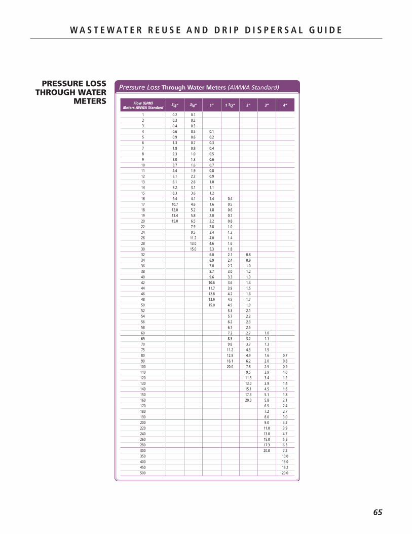
W A S T E W A T E R R E U S E A N D D R I P D I S P E R S A L G U I D E
65
W A S T E W A T E R R E U S E A N D D R I P D I S P E R S A L G U I D E
PRESSURE LOSS THROUGH WATER
METERS
Pressure Loss Through Water Meters (AWWA Standard)
Flow (GPM)Meters AWWA Standard
1 0.2 0.1 2 0.3 0.2 3 0.4 0.3 4 0.6 0.5 0.1 5 0.9 0.6 0.2 6 1.3 0.7 0.3 7 1.8 0.8 0.4 8 2.3 1.0 0.5 9 3.0 1.3 0.6 10 3.7 1.6 0.7 11 4.4 1.9 0.8 12 5.1 2.2 0.9 13 6.1 2.6 1.0 14 7.2 3.1 1.1 15 8.3 3.6 1.2 16 9.4 4.1 1.4 0.4 17 10.7 4.6 1.6 0.5 18 12.0 5.2 1.8 0.6 19 13.4 5.8 2.0 0.7 20 15.0 6.5 2.2 0.8 22 7.9 2.8 1.0 24 9.5 3.4 1.2 26 11.2 4.0 1.4 28 13.0 4.6 1.6 30 15.0 5.3 1.8 32 6.0 2.1 0.8 34 6.9 2.4 0.9 36 7.8 2.7 1.0 38 8.7 3.0 1.2 40 9.6 3.3 1.3 42 10.6 3.6 1.4 44 11.7 3.9 1.5 46 12.8 4.2 1.6 48 13.9 4.5 1.7 50 15.0 4.9 1.9 52 5.3 2.1 54 5.7 2.2 56 6.2 2.3 58 6.7 2.5 60 7.2 2.7 1.0 65 8.3 3.2 1.1 70 9.8 3.7 1.3 75 11.2 4.3 1.5 80 12.8 4.9 1.6 0.7 90 16.1 6.2 2.0 0.8 100 20.0 7.8 2.5 0.9 110 9.5 2.9 1.0 120 11.3 3.4 1.2 130 13.0 3.9 1.4 140 15.1 4.5 1.6 150 17.3 5.1 1.8 160 20.0 5.8 2.1 170 6.5 2.4 180 7.2 2.7 190 8.0 3.0 200 9.0 3.2 220 11.0 3.9 240 13.0 4.7 260 15.0 5.5 280 17.3 6.3 300 20.0 7.2 350 10.0 400 13.0 450 16.2 500 20.0
5/8” 3/4” 1” 1 1/2” 2” 3” 4”

W A S T E W A T E R R E U S E A N D D R I P D I S P E R S A L G U I D E
66
TEMPERATURE CONVERSION
Temperature Conversion
˚F ˚C
-450 -268
-440 -262
-430 -257
-420 -251
-410 -246
-400 -240
-390 -234
-380 -229
-370 -223
-360 -218
-350 -212
-340 -207
-330 -201
-320 -196
-310 -190
-300 -184
-290 -179
-280 -173
-273 -169
-270 -168
-260 -162
-250 -157
-240 -151
-230 -146
-220 -140
-210 -134
-200 -129
-190 -123
˚F ˚C
-180 -118
-170 -112
-160 -107
-150 -101
-140 -96
-130 -90
-120 -84
-110 -79
-100 -73
-90 -68
-80 -62
-70 -57
-60 -51
-50 -46
-40 -40
-30 -34
-20 -29
-10 -23
0 -17.8
1 -17.2
2 -16.7
3 -16.1
4 -15.6
5 -15.0
6 -14.4
7 -13.9
8 -13.3
9 -12.8
˚F ˚C
10 -12.2
11 -11.7
12 -11.1
13 -10.6
14 -10.0
15 -9.4
16 -8.9
17 -8.3
18 -7.8
19 -7.2
20 -6.7
21 -6.1
22 -5.6
23 -5.0
24 -4.4
25 -3.9
26 -3.3
27 -2.8
28 -2.2
29 -1.7
30 -1.1
31 -0.6
32 0.0
33 0.6
34 1.1
35 1.7
36 2.2
37 2.8
˚F ˚C
38 3.3
39 3.9
40 4.4
41 5.0
42 5.6
43 6.1
44 6.7
45 7.2
46 7.8
47 8.3
48 8.9
49 9.4
50 10.0
51 10.6
52 11.1
53 11.7
54 12.2
55 12.8
56 13.3
57 13.9
58 14.4
59 15.0
60 15.6
61 16.1
62 16.7
63 17.2
64 17.8
65 18.3
˚F ˚C
66 18.9
67 19.4
68 20.0
69 20.6
70 21.1
71 21.7
72 22.2
73 22.8
74 23.3
75 23.9
76 24.4
77 25.0
78 25.6
79 26.1
80 26.7
81 27.2
82 27.8
83 28.3
84 28.9
85 29.4
86 30.0
87 30.6
88 31.1
89 31.7
90 32.2
91 32.8
92 33.9
93 33.9
˚F ˚C
94 34.4
95 35.0
95 35.6
97 36.1
98 36.7
99 37.2
100 37.8
110 43
120 49
130 54
140 60
150 66
160 71
170 77
180 82
190 88
200 92
210 99
212 100
220 104
230 110
240 116
250 121
260 127
270 132
280 138
290 143
300 149
Degrees.Centigrade.(˚C). =. 5/9.x.(˚F-32)
Degrees.Fahrenheit.(˚F). =. 9/5.x.(˚C+32)

W062 11/12
NETAFIM USA5470 E. HOME AVE.FRESNO, CA 93727CS 888.638.2346F 800.695.4753www.netafimusa.com
WASTEWATERREUSE ANDDRIP DISPERSALDESIGN GUIDE
WASTEWATER DIVISION