WASHER DISINFECTOR
50
Instruction manual User Manual WASHER DISINFECTOR DS 50 DS 50 D Serial N°: 0051
Transcript of WASHER DISINFECTOR

Instruction manual
User Manual
WASHER DISINFECTOR
DS 50 DS 50 D
Serial N°:
0051

REV.2.04_COD.500065_A4 PAG. 2
Via Balegante, 27 31039 Riese Pio X (TV)
ITALY
Manufacturer:
STEELCO S.p.A. Via Balegante, 27
31039 Riese Pio X (TV) ITALY

REV.2.04_COD.500065_A4 PAG. 3
CONTENTS
1. GENERAL RULES ......................................................................................................................................5 1.1 LIMITS OF MANUFACTURER'S LIABILITY ....................................................................................................................... 5 1.2 MANUAL VALIDITY, CONTENTS AND CONSERVATION .................................................................................................... 5 1.3 REGULATIONS ........................................................................................................................................................ 6
2. SAFETY INFORMATION ............................................................................................................................7 2.1 INTENDED USE, IMPROPER USE ................................................................................................................................ 7 2.2 IMPORTANT WARNINGS AND SUGGESTIONS ................................................................................................................ 8 2.3 SAFETY RECOMMENDATIONS ................................................................................................................................... 8 2.4 RECOMMENDATIONS TO ENSURE HIGH QUALITY PERFORMANCE .................................................................................... 9 2.5 RESIDUAL RISKS ................................................................................................................................................... 10 2.6 SAFETY SIGNAL USED............................................................................................................................................ 11 2.7 TRAINING ............................................................................................................................................................. 12
2.7.1 STAFF QUALIFICATION ................................................................................................................................... 12 2.8 INDICATION OF SOUND LEVEL ................................................................................................................................. 13 2.9 TRANSPORT AND STORAGE .................................................................................................................................... 13
3. INSTALLATION (FOR THE INSTALLER ONLY) .....................................................................................14 3.1 ACTIVITY WARNINGS AND SUGGESTION ................................................................................................................... 14 3.2 POSITIONING ........................................................................................................................................................ 14
3.2.1 MOVEMENT, UNPACKING AND PLACING ............................................................................................................ 14 3.2.2 MAXIMUM FLOOR LOAD .................................................................................................................................. 15 3.2.3 POSITIONING OF THE MACHINE ....................................................................................................................... 15
3.3 WATER CONNECTION (FOR THE INSTALLER ONLY) .................................................................................................... 16 3.4 ELECTRICAL CONNECTION ..................................................................................................................................... 17 3.5 FUSE .................................................................................................................................................................. 18
3.5.1 REPLACEMENT OF FUSE ................................................................................................................................ 18 3.6 CHEMICAL PRODUCTS CONNECTIONS ...................................................................................................................... 19
3.6.1 PRESENCE SENSOR OF CHEMICAL PRODUCT .................................................................................................... 19 3.6.2 METER QUANTITY OF CHEMICAL PRODUCT ....................................................................................................... 19 3.6.3 REFILL OF CHEMICAL PRODUCT ...................................................................................................................... 19 3.6.4 WARNING .................................................................................................................................................... 20 3.6.5 INFORMATION ............................................................................................................................................... 20
3.7 CONNECTING THE DISCHARGE PIPE ........................................................................................................................ 21 3.8 WATER SOFTENER BUILT-IN (DS 50 D) ................................................................................................................... 22
4. CHECKS PRIOR TO START-UP ..............................................................................................................23 4.1 INTRODUCTION ..................................................................................................................................................... 23 4.2 CHECKS OF SAFETY SYSTEMS ................................................................................................................................ 23 4.3 GENERAL CONTROLS ............................................................................................................................................ 23
5. USING THE MACHINE (FOR THE USER) ...............................................................................................24 5.1 CHECKS .............................................................................................................................................................. 24 5.2 OPENING AND CLOSING THE DOOR .......................................................................................................................... 24 5.3 SWITCHING ON ..................................................................................................................................................... 24 5.4 PREPARATION ...................................................................................................................................................... 25 5.5 TREATMENT OF TURBINES AND STRAIGHT AND ANGULAR HAND PIECES (OPPOSED-ANGLES) .......................................... 26
6. CONTROL PANEL AND SYMBOLS USED .............................................................................................27 6.1 CONTROL PANEL .................................................................................................................................................. 27
6.1.1 BUTTONS .................................................................................................................................................... 28
7. WASHING PROGRAMMES ......................................................................................................................30
8. MACHINE STATUS ..................................................................................................................................31 8.1 WAIT .................................................................................................................................................................. 31 8.2 CYCLE ................................................................................................................................................................ 31 8.3 SHUTDOWN ......................................................................................................................................................... 31

REV.2.04_COD.500065_A4 PAG. 4
9. SPECIAL FEATURES ...............................................................................................................................31 9.1 POWER FAILURE ................................................................................................................................................... 31 9.2 RESET PROCEDURE .............................................................................................................................................. 31
10. WORK PROCEDURES .........................................................................................................................32 10.1 INTRODUCTION ..................................................................................................................................................... 32 10.2 INSTRUCTIONS TO PERSONNEL ............................................................................................................................... 32 10.3 DECONTAMINATION PROCEDURES .......................................................................................................................... 32
11. MENU ....................................................................................................................................................33 11.1 PARAMETER SETTINGS .......................................................................................................................................... 34
11.1.1 PARAMETERS LIST ........................................................................................................................................ 34 11.2 DETAILS OF THE ELECTRONIC CARD ........................................................................................................................ 36 11.3 FEATURES OF MASTER CARD ................................................................................................................................. 36
12. ALARMS AND EVENTS LIST ...............................................................................................................37 12.1 LOGICAL DESCRIPTION OF ALARM INTERVENTIONS .................................................................................................... 37 12.2 LIST OF ALARM MESSAGES ..................................................................................................................................... 37
13. PC INTERFACE.....................................................................................................................................38
14. CLOCK ..................................................................................................................................................38
15. HISTORICAL DATA ..............................................................................................................................38
16. MAINTENANCE .....................................................................................................................................39 16.1 GENERAL RECOMMENDATIONS ON MAINTENANCE ..................................................................................................... 39 16.2 PROCEDURE FOR ROUTINE MAINTENANCE WORK ...................................................................................................... 39 16.3 TABLE OF ROUTINE MAINTENANCE TASKS ................................................................................................................ 39 16.4 PROCEDURE FOR SPECIAL MAINTENANCE WORK....................................................................................................... 46 16.5 TABLE OF SPECIAL MAINTENANCE ........................................................................................................................... 46
17. PROBLEMS – CAUSES – SOLUTIONS ...............................................................................................49 17.1 INTRODUCTION ..................................................................................................................................................... 49 17.2 PROBLEMS - CAUSES - SOLUTIONS ........................................................................................................................ 49
18. DECOMMISSIONING ............................................................................................................................50 18.1 INSTRUCTIONS FOR DISASSEMBLY OF THE MACHINE .................................................................................................. 50 18.2 MACHINE DISPOSAL .............................................................................................................................................. 50
Thank you for purchasing this appliance.
The installation, maintenance and operating instructions given in the following pages have been prepared to
ensure the long life and good performance of the appliance.
Following the instructions carefully.
The appliance was designed and constructed using the latest technological innovations available.
Please take good care of it.
Your satisfaction is our best reward.
WARNING: NON OBSERVANCE, EVEN IN PART, OF THE RULES INDICATED IN THIS MANUAL WILL CAUSE
THE PRODUCT GUARANTEE TO BECOME INVALID AND RELIEVES THE MANUFACTURER OF ANY
RESPONSIBILITY.

REV.2.04_COD.500065_A4 PAG. 5
1. GENERAL RULES
1.1 Limits of manufacturer's liability The manufacturer shall not be held liable for failures or problems which arise due to tampering and/or incorrect applications and/or improper use of the machine. The purchaser must comply with all instructions set forth in the user's manual, and he must in particular:
Always work within the allowable limits for the use of the machine;
Always carry out constant and diligent maintenance;
Allow use of the machine by persons with proper skills and abilities for their role and purpose who have been properly trained and instructed;
Use only manufacturer original spare parts. Any modifications, adaptation or the like which may be made to machines which are subsequently placed on the market do not oblige the manufacturer to intervene on previously supplied machines, nor to consider the machine and the related user's manual lacking and inadequate. The installation, maintenance and operating instructions given in the following pages have been prepared to ensure the long life and outstanding performance of the appliance. For some especially demanding programming or maintenance operations, this manual serves as a memorandum of the main operations to be carried out. Education on these topics can be obtained by attending training course held by the manufacturer.
The instructions in this manual do not replace but rather are in addition to employer requirements to adhere to current legislation on standards of prevention and safety.
1.2 Manual validity, contents and conservation This manual reflects the state of the art at the moment of manufacture and delivery of the appliance and is valid for its entire life cycle.
The manufacturer is at clients' disposal for further information or to receive suggestions for making the manual more compliant with the needs for which it was prepared.
The translation of the contents into the client's language has been carefully prepared. In order to prevent possible accidents to persons or property due to in correct translation of the instructions, the client must:
Not perform operations or manoeuvres with the machine if there are any doubts or uncertainties about the operation to be performed; Ask technical service for clarification of the instruction.
If lost, ask for a new copy from the manufacturer.
It is important to keep this instruction manual with the machine for future reference. If the machine is sold or transferred, the manual must be handed over to the new owners or user in order for them to become acquainted with its functioning and the relative warnings.
Read the warnings carefully before installing and using the machine.
This is a translation of the Italian text, which prevails in case of doubts.

REV.2.04_COD.500065_A4 PAG. 6
1.3 Regulations The purpose of the warnings is to safeguard the user in compliance with following Regulations and “Technical Product Standards”:
EUROPE:
1993/42/EEC and s.m.i. (Medical Devices Directive);
2006/95/EC (Low Voltage Directive);
2004/108/EC (Electromagnetic compatibility directive);
EN 61010-1 (Safety);
EN 61010-2-040 (Safety);
and recognized international standards:
IEC 61000 (Electromagnetic compatibility);
ISO 14971 (Medical devices risk analysis);
IEC 61326-1 (Electromagnetic compatibility);
ISO 15883-1 (Cleaning efficacy);
ISO 15883-2 (Cleaning efficacy);
ISO/TS 15883-5 (Cleaning efficacy);
IEC 60529 (IP Grade).

REV.2.04_COD.500065_A4 PAG. 7
2. SAFETY INFORMATION Compliance with safety standards allow the operator to work productively and calmly, without the danger of harming himself or others. Before starting work, the worker must be completely familiar with the functions and proper operation of the machine. He must know the precise function of all command and control devices of the machine.
2.1 Intended use, improper use The intended use of the machine is the washing and thermal disinfection of instruments, equipment and objects. Therefore:
INTENDED USE:
Use is permitted of this machine only and exclusively for washing and thermal disinfection of orthodontic instruments, trays and objects normally used in orthodontic studios, hospital wards, assisted living centres, and so forth, like:
Scissors
Clogs
Glass works
Laboratory instruments
Improper use of this unit may be hazardous to the operator and may seriously damage the machine itself.
WARNING:
If the appliance is used in a manner not specified by the manufacturer, protection of the appliance may be
compromised.
IMPROPER USE:
Any use other than that for which the machine was intended is forbidden.

REV.2.04_COD.500065_A4 PAG. 8
2.2 Important warnings and suggestions For proper use of the machine, and in order to safeguard employed staff, carefully comply with the following general and specific standards.
THE OPERATOR MUST:
Carefully adhere to the provisions and instructions provided by the employer, managers and supervisors for individual and group safety.
Use safety devices appropriately and with care, as well as group and individual safety gear provided by the employer.
Immediately inform the employer, the manager and the supervisor of deficiencies in the aforementioned devices and means, as well as any hazardous conditions which he may become aware of, taking action directly in urgent cases within their scope of responsibilities and abilities to eliminate or reduce the deficiencies or hazards.
THE OPERATOR MUST NEVER:
Remove or modify, without authorization, the safety devices, nor those for signalling and measuring, nor the individual and group safety gear.
Undertake on his own initiative operations or manoeuvres which are not his responsibility which may compromise safety.
Insert foreign objects into the electrical parts. Do not insert foreign bodies into the covers of the electrical motors or into the moving parts of the machine.
Provide power to the machine by tampering with the main switch and the safety devices.
2.3 Safety recommendations If the new machine appears to be damaged, contact the retailer before starting it.
Any modification of electrical and hydraulic systems necessary to install the machine must be carried out by qualified, authorised persons only.
This machine must be operated by trained persons only;
The machine must be used for treatment and thermo disinfection of instruments for orthodontic and medical use and for laboratory glasses.
Any use other than that for which the machine was intended is forbidden.
The user is forbidden to carry out any work or repairs on the machine.
Technical Assistance for this washer disinfector should be carried out by qualified and authorised operators only.
The equipment should be installed by authorised persons only.
Do not install the equipment in rooms where there is the risk of explosion.
Do not expose the equipment to intense cold.
The electrical safety of this washer disinfector is only guaranteed if it is connected to an efficient earth system.
Take great care when handling detergents and additives: avoid contact, wear gloves and act in compliance with the safety recommendations indicated by the manufacturer of the chemical products.
Do not inhale the fumes produced by chemical products.
WARNING:
The chemical products are an irritant for the eyes, in case of contact rinse thoroughly with plenty of
water and consult a doctor.
If these products come into contact with the skin, rinse with plenty of water.
The water in the tank is not drinking water.
Do not lean on the door and do not use it as a step.
The machine reaches a temperature of 93°C during the work cycle: take great care to avoid burns.
Do not wash the machine using high-pressure jets of water.
Disconnect the machine from the electrical supply before carrying out maintenance work.
The acoustic pressure of the machine is below 70 dB(A).

REV.2.04_COD.500065_A4 PAG. 9
2.4 Recommendations to ensure high quality
performance
The user must oversee the machine during the cycle.
The injection tube for washing water must always be connected with the appropriated basket.
When the machine is running do not interrupt the cycle since this jeopardises disinfection.
Check periodically using chemical indicators to ensure correct disinfection.
Use recommended detergents and chemical additives only.
The use of other products may damage the machine.
During the manipulation of treated objects, it is required the use of appropriated PPE to prevent contact
with infected material and the risk of contamination.
Recommending chemical additives does not make the manufacturer responsible for any damage to the
materials and objects treated.
Do not introduce dirty instruments of substances that must not be discharged in sewage system (in
accordance with current legislation) but must be disposed in specific way.
Check that type of chemical product is suitable for the specific washing program used.
Follow the manufacturer's indications when using chemical products and use them for the foreseen
use only.
The machine was designed for use with water and chemical additives.
Do not use organic or other types of solvent as this may result in the risk of explosion or the rapid
deterioration of certain machine parts.
Residues of solvents or acids, particularly “hydrochloric acid”, can damage steel.
Contact should be avoided.
Use original accessories only.
Do never use soap powder.
Do never use foaming detergent.
The machine is to be used only with the baskets and or accessories included by the manufacturer.
Accessories which are not approved by the manufacturer may compromise the results achieved as well
as user safety.
Do never use chemical products based on chlorides (bleaches, sodium hypochlorite, hydrochloric acid
and so on).
These kinds of chemical detergents irreparably damage the machine and jeopardise the integrity of
materials and objects treated.
The taps of the water feeding must be always turned off, as the safety and diagnosis system will be deactivated,
in the following situations:
if the machine is left unused
if the machine is disconnected from the electrical connection
The manufacturer declines all responsibility for personal injury or material damage resulting from
the non-observance of the above rules.
The non-observance of these rules produces the total and prompt cancellation of the guarantee.

REV.2.04_COD.500065_A4 PAG. 10
2.5 Residual risks The appliance includes a series of fixed guards to prevent access to hazardous internal parts or zones.
It is however considered that the WASHER DISINFECTOR includes some residual risks. Hereunder for each phase or significant work intervention are useful measures to be taken:
PHASE BASKET LOADING
RISK Contusions and cuts to the upper limbs, due to accidental contact with due to falling or striking against tools, objects and instruments, mainly while loading and handling the basket.
MEASURE Assign staff that is instructed and equipped with work equipment (e.g. basket with protections, transport carts) and appropriate clothing and individual protection gear (e.g. shirts and protective gloves).
PHASE OBTAINING DETERGENTS/CHEMICAL ADDITIVES
RISK Contact with body parts with chemical washing products.
MEASURE
Assign staff that is instructed and equipped with appropriate clothing and individual protection gear. Wear clothing, gloves and goggles and act in compliance with the safety recommendations indicated by the manufacturer of the chemical products.
FIRST AID MEASURE
Immediately take off/remove clothing which has been contaminated or soaked by
the product.
If the substances come into contact with the skin, wash off affected skin areas
immediately and rinse with water.
RISK Inhalation of vapours of chemical wash products.
MEASURE
Assign staff that is instructed and equipped with appropriate clothing and individual protection gear. Comply with the safety instructions provided by the manufacturer of the chemical products and if there are none, wear a mask for the protection of the respiratory airways.
RISK Accidental release of chemical wash product
MEASURE
Do not flush concentrate into drains, surface or ground waters. Collect spillage with adsorbent material (e.g. sand, earth, vermiculite, diatomaceous earth). Flush away minor amounts with plenty of water.
IN CASE OF CONTACT WITH BODY OR RELEASE OF CHEMICAL PRODUCT LOOK
ALWAYS AT THE SAFETY MEASURES INDICATED IN THE CHEMICAL TECHNICAL
DATASHEET.
PHASE MAINTENANCE OF INTERNAL EQUIPMENT
RISK Burns of body parts by hot parts of the appliance.
MEASURE Allow maintenance to be performed only by trained personnel, equipped with appropriate clothing and individual protection gear. Wear suitable clothing and protective gloves.
PHASE EMISSION OF HAZARDOUS GAS
RISK Inhalation of vapours of hazardous gas
MEASURE
With a correct installation, concurring with the manufacturer prescription, using the authorized chemical product and concurring with the rules in force in your country, the machine don’t generate hazardous gas. However the machine is supplied with vapours discharge, that have to be connected concurring with the instruction on chapter 3.

REV.2.04_COD.500065_A4 PAG. 11
2.6 Safety signal used To inform personnel operating on the machines of obligations of behaviour and residual risks, adequate safety signals (as set forth by 92/58 EEC) are applied to the machine and near the work place. GENERIC SAFETY SIGNALS: In particular, labels with signals of obligation, prohibition and danger contained in this manual and pertinent to this machine and most commonly used are:
Electrical risk Warning!
See annex documentation
Caution hot surface
INDIVIDUAL SAFETY WEAR: The evaluation of risks for the health and safety of workers carried out in the workplace and on any equipment used, as well as the evaluation of residual risks as indicated, allow the employer to evaluate the need to adopt the individual protection gear which is most suitable and appropriate to be provided to workers. Considering the type of machine, it is felt that the individual protection gear should be provided to staff.

REV.2.04_COD.500065_A4 PAG. 12
2.7 Training Instructions for use of the machine will be provided by the STEELCO INSTALLATION TECHNICIAN during the start-up
phase to MACHINE OPERATORS and MAINTENANCE TECHNICIANS for their areas of responsibility, who will be thus instructed and trained.
It will be the duty of the EMPLOYER to check that the degree of staff training is suitable for assigned duties.
2.7.1 Staff qualification
Depending on the difficulty of certain installation operations, and of the operation and maintenance of the system, professional profiles are identified as follows:
Is INSTALLATION and REPAIR TECHNICIAN: Specialized installation and maintenance staff capable of carrying out all machine positioning and installation
operations, connection of various systems and machine start-up at the client's place of business, as well as all routine and special maintenance operations. This operator is responsible for training staff for machine operation and for testing the machine.
As RESPONSIBLE AUTHORITY FOR THE MACHINE IN THE WORKPLACE: Specialized staff assigned to the verification of safety devices and procedures for proper use of the machine in
complete absence or hazards.
The responsible authority is personally responsible for training courses for staff assigned to machine operation
and maintenance.
He must ensure that staff assigned to operation have acquired all information required for use and routine
maintenance of the machine, registering attendance and documenting comprehension tests.
The responsible authority must have a perfect understanding of all command, control and safety devices of the
machine.
He must inform all personnel assigned to machine operation and maintenance of the instructions concerning safety standards, the actions to be avoided and the first aid interventions connected with use of the machine and
the chemical wash agents it contains.
The responsible authority must be aware of all correct procedures for carrying out in absolute absence of danger
all operation and maintenance of the machine, as well as all procedures for disposal of any residual pollutants
and manufacturing wastes. He must always be present during extraordinary or routine maintenance and give his approval to proceed to staff
assigned to operation or to personnel assigned to routine or special maintenance.
The responsible authority will be responsible for operation of all command, control and safety devices in the
machines of the system.
He shall carry out scheduled verification of those devices in order to ensure their continued operation over time.
Ac MACHINE OPERATOR: Skilled personnel assigned to machine operation.
The machine operator must be perfectly aware of all of the machine's command and control devices. Only after approval by the safety supervisor, the machine operator must be capable of using the assigned commands to do the following:
Commissioning and start-up of the machine;
Loading and unloading of material to be washed in the baskets;
Operation of the machine in the various possible working modes, such as the start of various programmed wash cycles.
Programming and setting data from the operator panel, adjustment of single control devices during working phases, starting or resetting of work functions.
In addition, the machine operator must, by making use of all required individual protection gear and following adequate safety measures, be capable of performing some routine maintenance such as cleaning inside the machine, cleaning clogged filters, and disposing of pollutant waste materials produced during working.

REV.2.04_COD.500065_A4 PAG. 13
2.8 Indication of sound level The value shown refers to the measurement obtained on a machine of the same type as that covered herein and measured with an instrument at a height of 1.5 m at a distance of 1 m from the machine.
AVERAGE SOUND PRESSURE LEVEL: < 70 dB (A)
2.9 Transport and storage
Environment conditions:
Temperature range -5 ... +50 °C;
Relative Humidity range 20…90% without condensation;
Ventilation: Air exchange not required (required only if chemical tanks are installed).

REV.2.04_COD.500065_A4 PAG. 14
3. INSTALLATION (FOR THE INSTALLER ONLY)
3.1 Activity warnings and suggestion PREPARATION OF INSTALLATION SITE:
Arrangements for connections to the electrical and plumbing systems must be provided by the client prior to machine installation. Connections must be compliant with current directives in the country of installation. They must comply with the instructions contained in the documentation (provided on request) prior to machine installation.
ENVIRONMENT CONDITIONS:
Temperature range +5…+40 °C.
Relative Humidity range 20…90% without condensation.
Maximum altitude: 2.000 m SLM (for higher altitudes are available special versions of the device).
3.2 Positioning
3.2.1 Movement, unpacking and placing
The machine is delivered to the client fully packed, resting on a wood base and completely protected by cardboard covering.
LIFTING AND MOVEMENT:
Movement of the machine is provided using transport and lifting equipment and must be observed the following indications:
The lifting capability of the forklift must be greater than the total weight of the machine to be moved.
The machine must be kept as close as possible to the ground during movement.
Stack up: not allowed.
Rotation: do not turn upside down.
The forklift operator must perform movement only when there are no persons or objects in the
movement area.
UNPACKING AND PLACING:
Near the place of installation, unpack the machine. Carefully follow these steps:
All the packaging materials can be recycled.
Open the packaging carefully.
Do not overturn the machine as this may cause irreparable damage.
Cut the strap or open the box and remove the expanded polystyrene corner guards.
Remove the box followed by the nylon bag.
Caution: the bag represents a serious hazard for children and should be disposed of immediately.
Place the machine on the work surface and level it by adjusting the feet. The machine must be placed horizontally with a maximum inclination of 1÷2°.
Do not position the machine on surface which could cause a fire or fume hazard.

REV.2.04_COD.500065_A4 PAG. 15
3.2.2 Maximum floor load
For the installation of the machine, the floor must be able to sustain a minimum load of:
150 daN/m2
3.2.3 Positioning of the machine
In normal conditions, the minimum dimensions are suggested for the use of the machine in a single instal lation or with the coil nearby. For different installation ask for the distributors.
Minimum room ceiling height: Machine height (in m) + 0,3 m
Model with 1
load/unload door
0,2 m 0,2 m 0,2 m 0,2 m 0,2 m 0,2 m

REV.2.04_COD.500065_A4 PAG. 16
3.3 Water connection (for the installer only) To perform proper installation, account of following regulations:
The machine has been connected to the water distribution network following the in force rules;
Use only the tubes supplied with the machine;
Don’t cut short the rubber tubes supplied with the machine;
Make sure that mains water pressure is between 100 kPa (1 bar g) and 800 kPa (8 bar g); If it is below 100 kPa (1 bar g) dynamic pressure, you will need to install a pressure increase pump. If the pressure is higher than 800 kPa (8 bar g) a pressure reducer must be installed.
For machines equipped with steam condenser or water softener, the minimum pressure of water must be increased to 200 kPa (2 bar g) to ensure the correct functioning in terms of performance.
If the average hardness of the water is higher than 7 °f, decalcified water must be used;
For connection use cocks with an attachment of ¾”, located in an easily accessible location as near as possible to the machine;
Make sure that the general feeding tube is sufficient for the flow rate required from the machine and equipped with a general closing valve.
ATTENTION
For the specifications for water connections, refer to the plant installation.
During the machine installation, the installer must take the following step:
1. Identify the tubes supplied with the machine and make sure they are free from damages;
2. Identify the correspondence of the connection of flexible tubes to the water supply taps arranged in site, according to the references of the following chart.
CONNECTION COLOUR
HOT WATER RED
COLD WATER BLUE
DEMI WATER WHITE
3. Screw and tighten up the pipe sleeve to the connection arranged in site.
4. Remove any debris in the pipes or in the taps. To perform this operation open the tap and let the water flow in a pail.
5. Check the water temperature according to the specifications of the installation diagram.
6. Identify the correspondence of the connection of flexible tubes to the solenoid valve water supply of the machine.
7. Screw and tighten up the pipe sleeve to the connection arranged in site.
8. Open gradually the water supply taps and check the connections seal.
9. Terminated the connection, in case of water leaks repeat the procedure.
ATTENTION
The threaded connections can be easily damaged, therefore before to apply the maximum
clamping, screw manually the locking sleeve for some threads.
Information:
The back syphonage prevention system is already installed inside the machine concurring with IEC 61770;
If it isn’t available the double connection to hot and cold water, the two supply pipes must be connected together;
The manufacturer declines all responsibility for damage or injury caused by noncompliance of the rules
relating the supply installations.
If you don’t comply with the conditions above, the deriving damages will not warranty.
ATTENTION
When the machine is not in operation, always close the supply cocks.

REV.2.04_COD.500065_A4 PAG. 17
3.4 Electrical connection Connection of the machine to the electrical mains must be made by qualified, skilled personnel.
Power supply cable: It is compulsory for the retailer - installer to adapt the insulation class of the power supply cable to suit the working environment in compliance with Current Technical Regulations.
Check that the electric specifications match those shown in the label.
The machines are normally equipped with a three-phase 220/230/240 vac - 60hz power supply and three-phase with neutral 380/400/415 vac - 60hz power supply. For the specific voltage, please refer to the label on the machine.
The electrical connection must be carried out in compliance with current technical regulations.
Make sure that the mains voltage reading corresponds to the voltage indicated on the machine plate.
Check that the power supply voltage does not differ by more than 10% from its nominal value.
The frequency of the power supply voltage must not differ by more than 1% of its value.
Connection of the machine to the mains must be provided with an earth connection and an equipotential circuit as set forth by current standards.
Make sure that the electrical systems are efficiently earthed.
The earth conductor is to be connected to the earth terminal identified by the standard symbol.
The machine is equipped with a terminal identified by the relative symbol for equipotential connections between appliances (see rules for electrical plants).
Connect the machine using a power cord suitable for the electrical features of the machine and a disconnection system (not provided).
In case of prolonged unused of the machine is recommended that you execute the disconnection procedure of the electrical connection by placing the main-switch in "OFF" state.
The magnetothermal switch must be positioned in an accessible place, free and not covered from other
machine or anything that could obstruct the switch control.
The magneto-thermal switch must be provided with quality markings and must be indicated as an electrical shut-off device for the machine.
Near the magneto-thermal switch, a sign must be placed which reads:
DEDICATED DISCONNECTION DEVICE FOR MACHINE

REV.2.04_COD.500065_A4 PAG. 18
3.5 Fuse The fuses are used to protect the electrical circuits of machine from possible failure as overload or short circuits. If fuse takes action the downstream connections and their function are no longer available.
The fuses must respect the characteristics (size, dimensions and tripping characteristic) indicated in the wiring
diagram.
3.5.1 Replacement of fuse
ATTENTION
The replacement of fuse must be done from authorized operators only.
Before making the replacement procedure of fuse, establish and remove the cause of the fault.
If necessary, contact our technical assistance service.
Replacement procedure of fuse:
Log off the machine in safety condition by magnetothermal switch.
Access at the electrical panel.
Identify the fuse subjects to replacement, based on the wiring diagram.
Remove the related fuse from electrical panel.
Replace failure fuse with another fuse with same characteristics. The correct value of fuses are in the wiring
diagram.
If at the reactivation of electrical devices the new fuse intervene repeat the diagnosis and replacement procedure as
described previously.
ATTENTION
Use only fuses with the amperage and characteristics indicated in the wiring diagram.
The use of fuses other than those specified in the wiring diagram, void the warranty and can
cause the risk of damage the machine.

REV.2.04_COD.500065_A4 PAG. 19
3.6 Chemical products connections The dosing system of chemical products is composed of:
Dosing pump for chemical products.
Presence sensor chemical product.
The system can be equipped with meter quantity of dispensed product.
Further dosing pumps and accessories can be ordered as optional. Each pump is combined with a corresponding type of chemical, according with the references on the table below.
PRODUCT NOTE
DETERGENT
ACID / RINSE AID (OPT)
ATTENTION
In order to guarantee the right treatment of the objects, we suggest the use of specific products.
In the case of necessity, ask for advises to the seller or the producer.
3.6.1 Presence sensor of chemical product
Each dosing pump is combined with a sensor that confirm the presence of chemical product inside the container. If the product is scarce, the electronic control system of the machine send a message on video of lack of product.
3.6.2 Meter quantity of chemical product
Each dosing pump can be combined with a volumetric sensor for the quantity measurement of dispensed product. The electronic control system manages the value of required minimum quantity and, if necessary, stops the cycle.
3.6.3 Refill of chemical product
To refill the chemical product perform the following procedure:
Take the product container.
Switch off the machine.
Open the integrated chemical tank.
Insert the provided funnel in the
detergent tank.
Fill the tank by pouring in detergent.
Do not pour detergent outside the
tank.
Close the integrated chemical tank.
ATTENTION
The used chemical product can be dangerous if touched or inhaled. Before the use, read
carefully the safety information supplied by the manufacturer of the chemical product and the
label on the package.
During the operations of replacement of chemical product container, use the appropriate tools
for individual protection (chemical protective gloves, face masks for breathing, etc.).
The access to the technical compartment, where are located the chemical product containers, is
permitted only with keys and to the authorized personal.

REV.2.04_COD.500065_A4 PAG. 20
3.6.4 Warning
For the maximum amount of product which can be used for washing cycle, follow the instructions for the product you are using.
To ensure the efficiency of the chemical dosing system it is recommended to perform the calibration procedure every 6 months.
To ensure the efficiency of the dispenser pumps for chemical products it is important to service them regularly as described in chapter 16.
Use liquid chemical products only machine cannot function with powder detergent.
For the dispose of the chemical detergent and his tank follow the instruction indicated on the technical and safety data sheet provided by the manufacturer.
Check that type of chemical product is suitable for the specific washing program used.
Don’t place the chemical tank on the machine.
ATTENTION
Before undertaking any sort of special maintenance or movement of machine, empty tanks and
chemical dosing circuit from the chemical. It is advised to execute a treatment cycle without
chemical.
This procedure must be carried out in order to prevent contact of the chemical product with
body parts and machine components that can be damage.
3.6.5 Information
The machine has been validated in accordance with the provisions of Standard UNI EN ISO 15883.
The type test was carried out using the most widely known chemical products on the market, concerning the type of chemical products, the concentrations and the cycle parameters used you can ask the Manufacturer for details.

REV.2.04_COD.500065_A4 PAG. 21
3.7 Connecting the discharge pipe The discharge pipe connection should be checked carefully.
Use a discharge pipe suitable for organic and chemical materials and hot liquids.
The machine is equipped with a drain pipe with a diameter indicated on the installation plant.
CAUTION: if the discharge pipe is clogged take great care when processing the water and avoid contact with hands, eyes, etc. In the case of contact rinse the parts concerned with plenty of water. CONNECTING DRAIN PIPE: The drain pipe is connected to the sewer network in the following manner:
Identify the drain pipe and relative fittings, and assemble them.
Make sure the seal gasket is installed correctly.
On the back of the machine, identify the drain manifold and connect the hose via the union and ring nut.
Tighten the ring nut firmly.
Insert the drain hose and clamp it in place.
Insert the other end of the hose into the drain unit, fitting it properly and locking it in position.
IT IS NECESSARY TO FOLLOW THESE INSTRUCTIONS FOR DRAIN CONNECTION
Drain pipe must be connected by using a clamp.
Drain pipe must not present angles or irregular curving in its course.
Drain point must be placed at the same height of the machine drain point or on the floor.
FOLLOW CAREFULLY THESE INSTRUCTIONS AS A WRONG DRAIN CONNECTION CAN CAUSE THE BLOCK OF
MACHINE.
The diameter of main drain must be as indicated on the installation plant.
Avoid drain pipe extension.
ATTENTION
Drain must be done following International rules.
The manufacturer cannot be held responsible if an inaccurate use of machine causes
pollution.
If the discharge pipe is clogged take great care when processing the water and avoid contact
with hands, eyes, etc. In the case of contact rinse the parts concerned with plenty of water.
When the machine is connected to an exhaust ventilation system, the drain pipe should be
positioned externally of the building, protected from any animal access, and make sure that it
not causes any hazard.

REV.2.04_COD.500065_A4 PAG. 22
3.8 Water softener built-in (DS 50 D) The water softener built-in function is to reduce the anti-limescale quantity contained into the inlet water. If the machine is connected with hard water, the result is a rapid degeneration with lost in functions and performances. Regeneration must be done in order to maintain active ionic resins. For machines equipped with water softener, when installed, water hardness value must be introduced by entering into programmation (PRG switch 5 seconds), at parameter P16 and introduce one of the following values:
WATER HARDNESS (°f) SETTING PARAMETER CYCLES
0-10 Value 10 No regeneration
11-20 Value 20 Regeneration every 25 cycles
21-30 Value 30 Regeneration every 18 cycles
31-40 Value 40 Regeneration every 12 cycles
41-50 Value 50 Regeneration every 6 cycles
51-60 Value 60 Regeneration present at each cycle
(it is recommended for authorized people only).
The machine advise that it need a regeneration with a written on display “CLN” or “RIG”.
ACTIONS:
Open the door
Unscrew the plastic cap of salt box.
Spill 0.5 Kg of common salt inside the box by using the appropriate funnel.
WARNING: during this operation, pay attention do not let fall sail outside box.
Closed the plastic cap. After having introduce the basket, start with a normal washing cycle. Machine regenerates automatically.
A detail of the machine connections is shown on
the installation plant and electrical wiring.

REV.2.04_COD.500065_A4 PAG. 23
4. CHECKS PRIOR TO START-UP
4.1 Introduction The preliminary adjustments and controls are performed by a skilled technician, who has been specifically trained for this purpose.
4.2 Checks of safety systems Indicative list of adjustments and checks of safety systems and devices to be carried out:
Check the mains supply voltage;
Check the efficiency of the emergency and machine shutdown devices (circuit breaker);
Check the efficiency of the door opening safety micro switch;
Check the operation of machine controls, especially the START and STOP commands.
4.3 General controls Indicative list of general adjustments and checks to be made:
Check proper execution of general supplies of the machine (electrical and plumbing);
Ensure that the MACHINE OPERATOR is trained for its use;
Check that the motors installed on the machine rotate in the correct direction (only for machines equipped with tri-phase power supply motors).

REV.2.04_COD.500065_A4 PAG. 24
5. USING THE MACHINE (FOR THE USER)
5.1 Checks Check the quantity of chemical additives present and top-up if necessary as described below:
Obtain appropriate individual protection gear (gloves for protection from chemical substances, breathing protection masks, goggles etc.) and the new detergent container.
Turn off the machine.
Follow the instruction on sections 3.6.
ATTENTION:
The chemical product which is used may be hazardous if touched or inhaled.
Prior to use, carefully read the safety information provided by the detergent supplier and the label
applied to the package.
5.2 Opening and closing the door The machine is fitted with an electric door lock to prevent it being opened when the machine is running.
To open the door during a wash cycle, interrupt the cycle and remember that:
1. The items inside the machine may be very hot.
2. The entire wash cycle must be repeated.
5.3 Switching on Turn on the machine following the procedure:
Activate the magneto-thermal switch on the disconnection device as show below:
The control panel starts automatically.
Check that there are no alarm message. In negative case remove it.

REV.2.04_COD.500065_A4 PAG. 25
5.4 Preparation
WARNING:
Prior to placing instruments in the washer disinfector, remove materials like composite,
cement and amalgam following proper protocol an waste management.
Place the items to be washed inside the machine and position them carefully on the holder and in the rack.
Items should not overlap.
Receptacles should be positioned so that liquids can flow out easily.
Tall or heavy items should be placed towards the middle of the basket if possible to facilitate washing.
Make sure that nothing is blocking the arms and that they turn freely.
Place the load uniformly in the basket.
WARNING
The maximum load for each cycle is 8 Kg (basket included).
Never use the machine without basket !!!!
Below are shown some example of basket’s type available for the machine:
C640 C05
WARNING Do never emptying any solid waste into the machine (excrement, toilet paper etc.).
This will block the outlet system with pump and destroy the machine.
The treatment cycle has to be activated only if the basket is present into the machine
or if it is used a basket equipped with an injection system.
Non observance, even in part, of the rule here indicated, can cause dangerous
leakage of water from the door.

REV.2.04_COD.500065_A4 PAG. 26
5.5 Treatment of turbines and straight and angular hand
pieces (opposed-angles) Your machine can be equipped with a special basket studied specifically for washing hollow instruments, that need to be washed and for thermodisinfection both inside and outside the cavity.
CODE: C80
The above-mentioned basket is equipped with special accessories suitable for inserting the hand pieces. These supports are made in two parts, screwed together, between which there is a special filter. There is a rubber adaptor in the top part, available in two different diameters for the hand pieces.
We recommend washing the filters in the fitting for supporting the turbines and the hand pieces on a weekly basis, or replacing them with new filters.
The following operations should be performed for the correct treatment of the turbines and straight and angular hand pieces:
Prewash with cold water, to eliminate residues of blood and saliva.
Wash at 45°C, adding mineral-free, neutral-PH, liquid detergent.
Thermodisinfection at a temperature of 90°C for 1 minute, adding the additive for eliminating the residual water.
PRECAUTIONS:
Micromotors can’t be subjected to thermodisinfection treatment.
The thermodisinfection treatment can’t be done with the 90 °C program for 3 or 10 minutes.
Never use powder detergents.
REV.2.04_COD.500065_A4 PAG. 27
6. CONTROL PANEL AND SYMBOLS USED
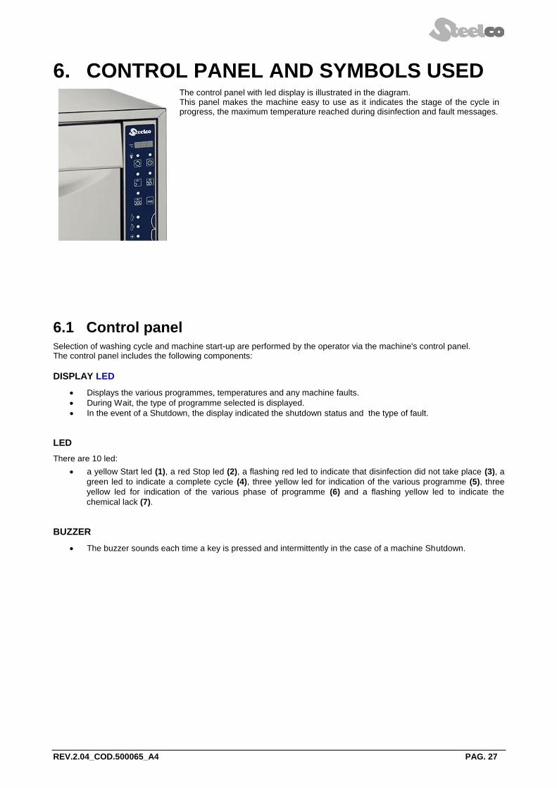
The control panel with led display is illustrated in the diagram. This panel makes the machine easy to use as it indicates the stage of the cycle in progress, the maximum temperature reached during disinfection and fault messages.
6.1 Control panel Selection of washing cycle and machine start-up are performed by the operator via the machine's control panel. The control panel includes the following components:
DISPLAY LED
Displays the various programmes, temperatures and any machine faults.
During Wait, the type of programme selected is displayed.
In the event of a Shutdown, the display indicated the shutdown status and the type of fault.
LED
There are 10 led:
a yellow Start led (1), a red Stop led (2), a flashing red led to indicate that disinfection did not take place (3), a
green led to indicate a complete cycle (4), three yellow led for indication of the various programme (5), three
yellow led for indication of the various phase of programme (6) and a flashing yellow led to indicate the
chemical lack (7).
BUZZER
The buzzer sounds each time a key is pressed and intermittently in the case of a machine Shutdown.

REV.2.04_COD.500065_A4 PAG. 28
6.1.1 Buttons
Programmes available to the user are the following:
BUTTONS DESCRIPTION
P1
Select "SHORT" cycle.
P2
Select “STANDARD” cycle.
P3
Select “INTENSIVE” cycle.
PRG
Keep pressed for five seconds during Wait or Shutdown to display the Menu. The programming menu access is reserved to specialized technician in possession of the password.
START
Select the programme required and press the relative switch to start the cycle.
STOP
This switch interrupts the cycle in progress, the card interrupts the process, a red led indicating that disinfection did not take place, keeps the door locked and if necessary indicates a high temperature inside the chamber. To return the machine to normal conditions the button must be pressed once more.

REV.2.04_COD.500065_A4 PAG. 29
PREWASH
MAIN WASH
HEATING
END CYCLE
STOP
P1
P3
(2/3)
(1)
(6)
(6)
(6)
(4)
(5)
(5)
(5)
(7)
DISPLAY
START
P2
PRG
DETERGENT

REV.2.04_COD.500065_A4 PAG. 30
7. WASHING PROGRAMMES The machine has three main washing programs in according to the necessity:
SHORT PROGRAMME P1 Suitable for lightly soiled items. Wash with detergent and thermal disinfection at 90°C for 1 minutes.
STANDARD PROGRAMME P2 Suitable for moderately soiled items. Pre-wash, wash with detergent and thermal disinfection at 90°C for 3 minutes.
INTENSIVE PROGRAMME P3 Suitable for heavily soiled items. Intensive pre-wash, wash with detergent and thermal disinfection at 90°C for 10 minutes.

REV.2.04_COD.500065_A4 PAG. 31
8. MACHINE STATUS 8.1 Wait The machine is ready to start a cycle. The diagnostics are active.
8.2 Cycle Cycle mode is entered by pressing the START key, this command is only accepted if the machine is in wait mode and the door is closed. The cycle carries out the foreseen stages. The diagnostics and regulators are active. The user interface gives information concerning the stage in progress.
8.3 Shutdown The diagnostics have detected a fault that causes the machine to shutdown, the cycle is suspended and the door remains locked.
The fault is indicated on the display and the user interface is ready for the door release sequence and the RESET
PROCEDURE to restore the machine to WAIT (see reset procedure).
9. SPECIAL FEATURES 9.1 Power failure When tension is restored after a power failure during PREPARING, WAIT or SHUTDOWN, the card returns to the previous programme. When tension is restored following a power failure with a cycle in progress, the card shuts down the machine (Er 0), indicates that the cycle has been interrupted and waits for the reset procedure to be carried out. The door remains blocked during all the power failure time.
9.2 Reset procedure In the event of a SHUTDOWN or when the stop key is pressed with a cycle in progress, the door remains locked. To open the door the door release sequence must be carried out from the keyboard as follows:
1. Press the STOP and START switch together and keep pressed for 5".
2. Press the programme switch P1 followed by the program switch P2 .
3. The machine is reset and returns to standby.
N.B.:
If the machine shutdown persists due to a fault in one of its components (e.g.: faulty probe, unsuitable levels,
etc.), the door is released and the machine remains inactive.
Seek technical assistance.

REV.2.04_COD.500065_A4 PAG. 32
10. WORK PROCEDURES
10.1 Introduction The machine was construct only for washing and thermal disinfection of orthodontic instruments, trays and objects normally used in orthodontic studios, hospital wards, assisted living centres, and so forth. It is therefore subject to constant contact with aggressive detergents and with contaminated instruments. For this reason, it is necessary to provide some useful instructions for the operators who will be using it.
10.2 Instructions to personnel The machine operator, in normal operating conditions, is not subject to risks if he works safely using suitable means of protection. In order to work safely the operator must:
Carefully comply with the instructions set forth in this manual.
Use safety devices appropriately and with care, as well as group and individual safety gear provided in the workplace.
Personally take action, or inform appropriate persons in the event of deficiencies in the aforementioned devices and means, as well as any hazardous conditions which he may become aware of, taking action directly in urgent cases within their scope of responsibilities and abilities to eliminate or reduce the deficiencies or hazards.
The maintenance technicians, in normal operating conditions, are not subject to risks if they work safely using suitable means of protection. In order to work safely the maintenance technician must:
Carefully comply with the instructions set forth in this manual.
Use safety devices appropriately and with care, as well as group and individual safety gear provided in the workplace.
Use special care in making repairs or replacing mechanical parts (e.g. drain pump, etc.) on malfunctioning machines which have not completed the thermal disinfection cycle.
10.3 Decontamination procedures When making repairs or replacing mechanical parts (e.g. drain pump, heating element, etc.) on malfunctioning machines that have not completed the thermal disinfection cycle, before undertaking any sort of maintenance on the internal parts of the machine, the disinfection procedure must be carried out in order to eliminate any pathogenic residues and protect operators who come into contact with the machine from the risk of infection. The decontamination procedure must be performed by the system operator, who must be equipped with all provided individual protection gear. MACHINE STATUS: The machine must not be powered electrically and the magneto-thermal switch must be in the OFF position (see figure on section 4.4). The person performing the task must ensure that there is no-one around the machine during this operation. SAFETY SYSTEMS TO BE ADOPTED: The operation must be carried out in compliance with standards governing the use of disinfectant substances used (see technical information for the product being used, provided by the manufacturer), in compliance with standards concerning contact with parts of the machine which may be contaminated by pathogenic materials and with use of individual protection gear. MODE OF INTERVENTION: If possible, dry run a cycle for thermal disinfection of the wash chamber. Open the wash chamber door and spray evenly with a suitable disinfectant. Cover all internal parts as well as any basket and the instruments it may contain. Wait for the amount of time required for disinfection (see technical information for the disinfectant product). When performing maintenance on parts of the machine which have not been reached by the disinfectant, take appropriate precautions and use suitable safety gear.

REV.2.04_COD.500065_A4 PAG. 33
11. MENU To enter the menu keep the PRG key pressed for 5 seconds. Operations, to enter into phases for programming, setting, time regulation and printing, are as follows:
ACTION PHASE DISPLAY
KEYS SEQUENCE TO ENTER INTO “PARAMETER MENU”
Press PRG for 5 seconds P A r
Press START P A S
Press P1 Password
Press P1 and P2 Select the parameter P1 ÷ P47
Press START Modify parameters with P1 and P2 Value
KEYS SEQUENCE FOR TIME REGULATION
Press PRG for 5 seconds P A r
Press PRG C L O
Press START Modify with P1 and P2 Input day
Press START Modify with P1 and P2 Input month
Press START Modify with P1 and P2 Input year
Press START Modify with P1 and P2 Input hour
Press START Modify with P1 and P2 Input minutes
Push START to go out from
regulation
KEYS SEQUENCE FOR PRINTING HISTORICAL DATAS
Press PRG for 5 seconds P A r
Press PRG C L O
Press PRG P r n
Press START All memorized cycles are printing
KEYS SEQUENCE TO DELETE ALL HISTORICAL EVENTS
Press PRG for 5 seconds P A r
Press PRG C L O
Press PRG P r n
Press PRG E r a
Press START P A S
Press P1 Insert Password
Press START
Starting in deleting historical
events.
After this operation, all memorized
cycles are deleted.
KEYS SEQUENCE FOR MACHINE WORKING HOURS VISUALIZATION
Press PRG for 5 seconds P A r
Press PRG C L O
Press PRG P r n
Press PRG E r a
Press PRG S E r
Press START The machine displays the working
hours. Value

REV.2.04_COD.500065_A4 PAG. 34
11.1 Parameter settings
To set the parameters will be requested a password, that will be entered using P1 and P2 keys. If the password entered is wrong, you will quit the menu immediately.
Pressing instead P1 and P2 keys it will be possible to scroll through the various parameters. Press
START button to enter.
Pressing P1 and P2 keys it is possible to increase or decrease the value of the various parameters once selected them.
If the parameters are not modified, it is possible to quit the parameters menu keeping pressed the STOP key for 5 seconds.
ATTENTION:
The access to the programming mode is restricted only to authorized and skilled technicians which
are supplied with the password.
The password must be obtained from the manufacturer.
11.1.1 Parameters list
PARAM. DESCRIPTION sw.v.6.03 UNIT MIN MAX
P01 Set-up disinfection temperature cycle 2 and cycle 3 °C 85 93
P02 Set-up disinfection temperature cycle 1 °C 55 93
P03 Disinfection time cycle 3 Sec. 60 600
P04 Washing time for neutral phase Sec. 1 180
P05 Prewashing time cycle 2 and cycle 3 Sec. 30 120
P06 Time 1° washing Sec. 30 600
P07 Disinfection time cycle 2 Sec. 60 600
P08 Loading time of rinse-aid cycle 2 Sec. 0 30
P09 Regeneration time ( water softner built-in) Sec. 480 900
P10 Drain time before disinfection Sec. 0 60
P11 Drain time during cooling Sec. 0 60
P12 Water loading time during cooling Sec. 0 60
P13 Detergent loading time Sec. 0 60
P14 Water loading time during regeneration (water softner built-in) Sec. 40 150
P15 Maximum waiting time in lock door Sec. 0 10
P16
Lime-scale value 10 : no regeneration 20 : regeneration every 25 cycles 30 : regeneration every 18 cycles 40 : regeneration every 12 cycles 50 : regeneration every 6 cycles 60 : regeneration each cycle
FR° 1 6
P17 Drain time during last cooling period Sec. 10 30
P18 Maximum waiting time cold water loading Sec. 0 999
P19 Maximum waiting time of drain Sec. 0 999
P20 Maximum time of heating elements functioning Min. 0 60

REV.2.04_COD.500065_A4 PAG. 35
PARAM. DESCRIPTION sw.v.6.03 UNIT MIN MAX
P21 Maximum waiting drain time during water loading Sec. 0 240
P22 Disinfection temperature fluctuation °C 1 10
P23 Loading time of detergent for filling up pipe Sec. 0 60
P24 Loading time of rinse-aid for filling up pipe Sec. 0 60
P25 Excludable phase on cycle 3 (0=OFF; 1=ON) Sel. 0 1
P26 Redundancy probe (0=not present, 1= on slave board, 2=on master board) Sel. 0 2
P27 Hot washing temperature °C 40 80
P28 Disinfection time cycle 1 Sec. 1 600
P29 Excludable phase on cycle 1 (0=OFF; 1=ON) Sel. 0 1
P30 Excludable phase on cycle 2 (0=OFF; 1=ON) Sel. 0 1
P31 Acid detergent dosing pump (0) / rinse-aid dosing pump (1) Sel. 0 1
P32 Loading time of acid detergent Sec. 0 60
P33 Chemical block selection: 0=no block in case of chemical lack 1=no possibility to make cycle in case of chemical lack
Sel. 0 1
P34 Number of regeneration to load salt Sel. 0 18
P35 Time lag in opening 1/10 sec 0 100
P36 Time lag in closing 1/10 sec 0 100
P37 Print enable (0=not enable 1= enable) Sel. 0 1
P38 Washing time for hot washing phase on cycle 2 sec 0 999
P39 Washing time for hot washing phase on cycle 3 sec 0 999
P40 Max chamber probes disparity °C 0 99
P41 Door safety for UL conformity Sel. 0 1
P42 Rinsing phase time during regeneration sec 0 999
P43 A0 temperature interval °C 0 99
P44 A0 temperature reference °C 0 99
P45 A0 lower temperature limit °C 0 99
P46 Show the A0 value on the display (0=not enable 1= enable) Sel. 0 1
P47 Demi water for disinfection phase Sel. 0 1

REV.2.04_COD.500065_A4 PAG. 36
11.2 Details of the electronic card The electronic card was design for the control of the washer machine. Any use other than that specified above. The electronic card was designed following the indications given in the standards below:
EN 60335 low voltage
EN 61000-6-3 emissions
EN 61000-6-1 immunity
11.3 Features of master card
Serial interface
Com1: Low voltage bus bar for two-way communication with the keyboard card.
Com2: Asynchronous serial interface type RS232 foreseen for connection to PC or printer.

REV.2.04_COD.500065_A4 PAG. 37
12. ALARMS AND EVENTS LIST
12.1 Logical description of alarm interventions During machine operation, the operator is aided by ALARMS or ALARM MESSAGES which make use of visual signals on the operator display panel to advise him of possible anomalies in progress and machine alarms which have intervened.
Intervention of an ALARM during operation of the system is signalled to the operator by a message on the operator panel. The alarm which appears on the panel remains active until the cause of intervention is removed. The intervention of an alarm stops the wash cycle currently in progress.
12.2 List of alarm messages Possible alarms which may intervene during a work cycle are shown on the control panel display. The message includes the number of the alarm that has intervened. A complete list of possible alarm messages follows.
ALARMS DESCRIPTION
Er 0 POWER FAIL It shows power failure during cycle.
Er 2 DISINFECTION
INCOMPLETE
This occurs when the temperature does not reach the required value for disinfection.
Er 3 DOOR LOCK This condition happens when, during a cycle, the reel is deactivated, so the door is unblocked. Or, after the start the reel do not activate its limit switch within the time set by the parameter P15.
Er 4 DOOR OPEN This occurs when the limit switch of the door lock is disengaged during a work cycle and the door results as locked but open.
Er 5 WATER SHORTAGE
This occurs when solenoid valve is open but the tank does not reach the required water level within the set time (P18). Possible causes for this condition are lack of water or incorrect parameter setting.
Er 6 HEATING ELEMENTS
PROTECTION
This condition happens when ,with heaters ON, the disinfection do not ends within the time set by the parameter P20. Likely reasons of such a block could be either a problem on eating elements or a too low set time by the parameter.
Er 7 TEMPERATURE
PROBE 1 This occurs when the chamber temperature probe is damaged.
Er 8 TEMPERATURE
PROBES DIFFERENT This occurs when the temperature probes is different.
Er 9 TEMPERATURE
PROBE 2 This occurs when the chamber temperature probe is damaged.
E 10 DISCHARGE PUMP This occurs when the presence of liquid is detected following the discharge stage.
E 11 NO CHEMICAL Lack of chemical (enabled if P33=1).
E 13 CAN SERIAL
CONNECTION Lack of CAN communication between the two boards.
E 14 NO DEMI WATER This occurs when solenoid valve is open but the tank does not reach the required water level within the set time (P18). Possible causes for this condition are lack of water or incorrect parameter setting.
IF A FAULT ARISES DO NOT ATTEMPT TO RESOLVE IT YOURSELF, ASK FOR THE ASSISTANCE OF
AN AUTHORISED TECHNICIAN.
In case of short voltage drop the machine can give ER3 (door lock) instead of POWER FAILURE: if when alarm ER3 appears the door is unlocked, and consequently it can be opened, the error is without doubt due to a short no power.
N.B.: The power failure error is given only when there is no power during a working cycle.

REV.2.04_COD.500065_A4 PAG. 38
13. PC INTERFACE The card has a communication channel RS232 with Modbus protocol. The channel can be used to access the historical data records file by setting the printer as follows:
baud rate: 2400 baud, X ON X OFF
data bits: 8 bits,
parity: none.
14. CLOCK The card has a real-time clock.
Time readings are also used when recording historical data.
15. HISTORICAL DATA During the working cycle, the machine memorizes on a card all the working data of the wash cycles that have
been performed.
The card is able to record the fields described below for up to a max. of 4.000 cycles in the permanent memory. The fields given in the example below are recorded for each cycle:
DATE START TIME PROGRAMME MAX °C HOLD>85°C FAULTS
12.00 Short 93°C 60 seconds 01
13.05 Standard 94°C 180 seconds 01
When 95% of the memory is full the dump memory message appears on the display. To remove the message it is necessary to print or delete the historical.
The various causes for machine shutdowns are indicated in the FAULTS section, the faults are identified by numbers as shown.

REV.2.04_COD.500065_A4 PAG. 39
16. MAINTENANCE
16.1 General recommendations on maintenance The machine was constructed only for washing and thermal disinfection of orthodontic instruments, trays and objects normally used in orthodontic studios, hospital wards, assisted living centres, and so forth. It is therefore subject to constant contact with aggressive detergents and with contaminated instruments. For this reason it is necessary to provide some useful instructions for the operators who will be performing maintenance on it.
The maintenance technicians, in normal operating conditions, are not subject to risks if they work safely using suitable means of protection. In order to work safely the maintenance technician must:
Carefully comply with the instructions set forth in this manual.
Use safety devices appropriately and with care, as well as group and individual safety gear provided in the workplace.
Use special care in making repairs or replacing mechanical parts (e.g. drain pump, etc.) on malfunctioning machines which have not completed the thermal disinfection cycle.
Maintenance operations for the machine described in this manual can be divided into "Routine Maintenance" and
"Special Maintenance".
GENERAL GUIDELINES:
MACHINE STATUS The machine must not be powered electrically and the magneto-thermal switch must be in the OFF position. The person performing the task must ensure that there is no-one around the machine during this operation.
SAFETY SYSTEMS TO BE ADOPTED The operation must be carried out in compliance with standards governing the use of disinfectant substances used (see technical information for the product being used), in compliance with standards concerning contact with parts of the machine which may be contaminated by pathogenic materials and with use of individual protection gear.
16.2 Procedure for routine maintenance work Routine maintenance includes all operations aimed at keeping various parts of the machine clean and functional. They must be performed on a regular basis (see table in paragraph 16.3) or when considered necessary due to incorrect performance of washing cycle. Since these are simple cleaning operations, they are normally performed by the machine operator on his own liability.
16.3 Table of routine maintenance tasks The following table shows the various routine maintenance tasks, their frequency, who is to perform them and the reference to the specific intervention form. Each single task is more fully explained in the single reference forms. Even if the water supply is relatively soft, the high temperature can cause the formation of residues which may create problems with the heating element, compromising the correct wash cycle and the reaching of the disinfection temperature. For these reasons it is advisable to carry out regular cleaning as described below.

REV.2.04_COD.500065_A4 PAG. 40
TABLE OF ROUTINE MAINTENANCE TASKS
N.B.: Routine maintenance tasks must be performed at the intervals set forth in the table. It is however advisable to carry out single cleaning tasks anytime you feel they may be necessary.

REV.2.04_COD.500065_A4 PAG. 41
It is advisable to carry out a general check-up and to clean the appliance regularly,
particularly if the supply water is very hard.
Particular attention should be paid to heating element and the probe of thermostats.
WARNING: Do not clean the machine outside with high pressure water.
Please contact the retailer that supplies your cleaning products for details of recommended methods and products for sanitizing the machine regularly.
The machine has a safety thermostat that shuts down the power supply to the heating elements in the event of overheating.
Before turning the machine back on, you will need to eliminate the problem and wait for the temperature to drop back below operating levels.
To re-start the appliance the fault that caused overheating must be corrected.
Every 12 months
Clean the diaphragms of solenoid valves and replace if necessary.
Clean the thermostat probe.
Change the membrane pipe inside dosing pump.
Even if the supply water is soft, the high working temperatures may cause limescale to build-up. Apart from damaging the resistors, limescale can also clog the nozzles in which case the correct tank temperature for thermodisinfection may not be reached.
WARNING
IT IS NECESSARY TO MAKE A MAINTENANCE AT REGULAR INTERVALS, THIS MEANS EVERY 3 MONTHS, IN
ORDER TO GUARANTEE THE PERFECT FUNCTIONING OF PUMPS DOSING CHEMICAL PRODUCTS.

REV.2.04_COD.500065_A4 PAG. 42
CLEANING OF WASHING CHAMBER DRAIN FILTERS
M1 Worker: Ac Frequency of Intervention: 3 months
METHOD OF INTERVENTION: clean the washing chamber drain filters in the following manner:
Open the washing chamber door and extract the basket.
Extract the drain water filtering assembly from the chamber.
Unscrew the threaded pin and remove the cover of the drain water filter basket.
Clean the drain water filter basket. Remove residues deposited during various wash cycles.
Remove and clean any deposits and incrustations from the wash chamber drain.

REV.2.04_COD.500065_A4 PAG. 43
Replace the clean filter on the washing chamber drain.
Put the cover for the drain water filter back in place. Lock it in position with the threaded pin.
Put the drain water filter group back in the wash chamber.
CLEANING OF WASHING CHAMBER THERMOSTAT PROBE
M2 Worker: Ac Frequency of Intervention: 3 months
METHOD OF INTERVENTION: clean the washing chamber thermostat probe in the following manner:
Open the washing chamber door and extract the basket.
Check the washing chamber thermostat probe and clean it of any deposits or lime incrustations using a damp cloth and an appropriate detergent.
Take care not to damage or move the probe.

REV.2.04_COD.500065_A4 PAG. 44
CLEANING OF WASHING ROTORS
M3 Worker: Ac Frequency of Intervention: 3 months
METHOD OF INTERVENTION: clean the washing rotors as follows:
Open the washing chamber door and extract the basket.
Unscrew the fastening pin of the two rotors and extract them from the chamber.
Unscrew the closure plug of the rear part of the nozzle and remove it.
Carefully cleaned and remove any incrustations from the washing rotor nozzles using appropriate detergents.
Put the plugs back in place at the ends of the washing arms.
Make sure the gasket is properly positioned and in good condition.
Replace it if necessary.
Put the rotors back on the machine.
Lock them in place with the previously removed fastening pin.

REV.2.04_COD.500065_A4 PAG. 45
CLEANING AND CHECKING WASHING CHAMBER INSTRUMENTATION
Worker: Ac Frequency of Intervention: 8 h
METHOD OF INTERVENTION:
Open the access door to the washING chamber and check that no equipment, trays or instruments have been left in
the wash basket.
Spray the inside of the wash chamber evenly with a disinfectant.
Cover all internal parts.
Wait for the amount of time required for disinfection (see technical information for the disinfectant product).
CLEANING THE EXTERNAL BODY OF THE MACHINE
Worker: Ac Frequency of Intervention: 8 h
METHOD OF CLEANING OUTER BODY
Use a damp cloth to clean the outer body of the machine.
Use only neutral detergents.
Do not use abrasive detergents or solvents and/or thinners of any kind.
METHOD OF CLEANING MARKING LABEL
Use a damp cloth to clean the marking label surface. Use only water or isopropyl alcohol. Do not use abrasive detergents or solvents and/or thinners of any kind.
METHOD OF CLEANING CONTROL PANEL
Clean the control panel using only a soft cloth dampened with a product for the cleaning of plastic materials.
ANTI-LIMESCALE TREATMENT
Worker: Ac Frequency of Intervention: 1 week
METHOD OF INTERVENTION:
Use an incrustation removal product when necessary during a dry run (usually once a week unless the amount of
water requires daily use to prevent lime build-up and clogging of the water jets).
This product should be applied using 100 ml of incrustation remover poured into a container of the same size located
on an empty basket.
Start the standard cycle. Stop the cycle before the thermal disinfection phase.
DISINFECTION TREATMENT
Worker: Ac Frequency of Intervention: 1 week
METHOD OF INTERVENTION:
Start a washing cycle (recommended short cycle) with empty machine and with basket present.
This will guarantee the complete disinfection of the washing chamber, of the basket and of the hydraulic circuits.

REV.2.04_COD.500065_A4 PAG. 46
16.4 Procedure for special maintenance work All special maintenance work is to be performed only by qualified, skilled personnel. A table is shown below which includes possible special maintenance work that may be required. If your machine should require special maintenance, please contact your retailer/distributor.
16.5 Table of special maintenance
See scheduled maintenance form table.
CLEANING OF COLD EATER INLET FILTERS
M4 Worker: Is Frequency of Intervention: 3 months
METHOD OF INTERVENTION: clean (or replace) the filter on the cold water supply tube as described below:
Close the water supply tap.
Loosen and completely unscrew the water supply pipe.
Remove the filter located inside the water supply pipe fitting and clean it, removing any incrustation or deposits by
immersing it in a container of water, or in appropriate lime removal products if required.

REV.2.04_COD.500065_A4 PAG. 47
REPLACEMENT THE MEMBRANE PIPE OF DISPENSING PUMP
M6 Worker: Is Frequency of Intervention: from 3 to 6 months
METHOD OF INTERVENTION: replace the membrane pipe of dispensing pump for chemical products as described
below:
1. Remove the closure panel of the machine by removing the screws.
2. Access the chemical product pump. Use a tool to remove the protective mask of the rotor.
3. Extract the membrane pipe from the dispensing pump.
4. Turn the rotor manually, clockwise, until the membrane pipe is fully extracted from the dispensing pump.
ATTENTION: the rotor of dispensing pump
turns ONLY clockwise !!!
5. Place the membrane pipe in vertical position to help the flow of chemical product from membrane tube to chemical circuit. Do this operation to prevent leakage of chemical product during replacement.
6. Loosen the tube clamps and disconnect the product supply tubes from the membrane pipe attachments.
7. Replace the membrane pipe with an other the same type. (see the spare part list).

REV.2.04_COD.500065_A4 PAG. 48
8. Replace the membrane pipe into dispensing pump, manually operating the rotor.
9. Replace the protective mask of the rotor.
ATTENTION: the rotor of dispensing pump turns
ONLY clockwise !!!
N.B.: Every 3/6 months, it is advisable to replace the membrane pipe of the dispensing pump.
CLEANING OF DISPENSING PUMP FOR CHEMICAL PRODUCTS
M6 Worker: Is Frequency of Intervention: 3 months
METHOD OF INTERVENTION: clean the pump for the dispensing of chemical products as described below:
Remove the closure panel of the machine by removing the screws.
Access the chemical product pump. Use a tool to remove the protective mask of the rotor.
Loosen the tube clamps and disconnect the product supply tubes from the membrane tube attachments.
Turn the rotor manually, clockwise, until the membrane tube is fully extracted from the dispensing pump.
Apply an even layer of silicon grease to the membrane tube you have just removed before re-installing it on the dispensing pump, following the previously described operations in reverse order.
CLEANING OF SAFETY SIGNALS SURFACES
Worker: Is Frequency of Intervention: 1 year
METHOD OF INTERVENTION:
Clean the safety signals surfaces with water or isopropyl alcohol, using a cloth.
WARNING
In order to remove the scale, suitable products can be used, yet pay attention that they are not highly corrosive.
ASSISTANCE
If a normal functioning of the machine is not achieved, even after interventions of ordinary maintenance, get in touch with our service assistance stating that kind of the defect, the model and the serial number of the machine.

REV.2.04_COD.500065_A4 PAG. 49
17. PROBLEMS – CAUSES – SOLUTIONS
17.1 Introduction This chapter includes possible problems which may occur during machine operation, along with their cause and solution. All components, if not identified by specific figures, are referred to by the attached assembly drawings. If after following all instructions in this chapter the problems persist or re-occur frequently, please contact our technical service.
17.2 Problems - Causes - Solutions
P. MACHINE WILL NOT START:
C. Circuit breaker de-activated.
S. Place it in the "ON" working position.
C. Machine start switch de-activated.
S. Press the start button.
P. UPON GIVING START-UP COMMAND, WASHING CYCLE DOES NOT START:
C. The door is not correctly closed or locked.
S. Check door closure. Check that the door micro-switch is properly activated.
C. Micro-switch failure.
S. Check operation and replace as necessary.
C. No detergent in tank.
S. Turn the machine off and fill the tank.
P. MACHINE DOES NOT REACH SET TEMPERATURE FOR THE SELECTED WASHING CYCLE:
C. The thermostat probe of the washing chamber is dirty or covered with lime.
S. Clean the thermostat probe of the washing chamber, performing the routine maintenance described in chapter 16 (Form M2) of this manual.
P. MACHINE DOES NOT PROPERLY RUN WASHING CYCLE:
C. The nozzles of the washing rotors are clogged my deposits or lime.
S. Clean the rotors by carrying out the routine maintenance set forth in chapter 16 (Form M3) of this manual.
C. Water required for proper washing does not arrive.
S. Ensure that the water is supplied at the correct pressure and that there are no obstructions.
C. The correct amount of water required for correct washing cycle does not arrive.
S. Completely close the tap for connection to the plumbing system located upstream from the machine and clean the filter as described in chapter 16 (form M1) of this manual.
P. DETERGENT FILLING PHASE DOES NOT OCCUR CORRECTLY:
C. Chemical dispensing pump not very efficient.
S. Perform the routine maintenance set forth in chapter 16 (Form M6) of this manual.
C. Chemical dispensing pump failed.
S. Contact our technical service and ask for the assistance of an authorized workshop technician for the repair or replacement of the pump.

REV.2.04_COD.500065_A4 PAG. 50
18. DECOMMISSIONING
18.1 Instructions for disassembly of the machine
For demolition and subsequent disposal of your machine, proceed as follows:
Disconnect the machine from the electrical power and water supply, and from the drain. With the machine disconnected, check that the water circuit is not pressurized.
Contact the organization responsible for reporting and certifying machine demolition, in accordance with the laws in the country where the machine is installed.
Carry out draining, storage and subsequent disposal of substances such as oils and grease which may be in the lubrication tanks in accordance with the law.
When disassembling the machine, make sure to divide the materials it is made of according to their chemical makeup (iron, aluminium, bronze, plastic, etc.).
Ensure that the floor where the machine or any parts of it are placed is made of washable materials, non-absorbent, and provided with adequate drainage to protect against accidental oil leaks or rust.
These drains must carry any leakage to watertight collection containers.
Cover the machine or parts of it with insulating covers to prevent rain or humidity from damaging the structure through oxidation or rust.
Following the legal requirements where the machine is installed and used, dispose of all materials
and substances resulting from its disassembly.
18.2 Machine disposal
For the dispose of the equipment get through to the manufacturer or distributor.
Do not dispose of this equipment as miscellaneous solid municipal waste, but arrange to have it collected separately.
The re-use or correct recycling of the electronic and electrical equipment (EEE) is important in order to protect the environment and the well-being of humans.
In accordance with European Directive WEEE 2002/96/EC, special collection points are available to which to deliver waste electrical and electronic equipment and the equipment can also be handed over to a distributor at the moment of purchasing a new equivalent type.
The public administration and producers of electrical and electronic equipment are involved in facilitating the processes of the re-use and recovery of waste electrical and electronic equipment through the organisation of collection activities and the use of appropriate planning arrangements.
Unauthorized disposal of waste electrical and electronic equipment is punishable by law with the appropriate penalties.