
Warrior™ 400i CC/CV Warrior™ 500i CC/CV -...
32
Instruction manual 0463 340 030 GB 20181009 Valid for: Serial no. 339-xxx-xxxx Warrior™ 400i CC/CV Warrior™ 500i CC/CV
Transcript of Warrior™ 400i CC/CV Warrior™ 500i CC/CV -...
Instruction manual
0463 340 030 GB 20181009 Valid for: Serial no. 339-xxx-xxxx
Warrior™ 400i CC/CVWarrior™ 500i CC/CV
TABLE OF CONTENTS
0463 340 030 © ESAB AB 2018
1 SAFETY ....................................................................................................... 31.1 Meaning of symbols ............................................................................... 31.2 Safety precautions ................................................................................. 31.3 User responsibility ................................................................................. 71.4 California Proposition 65 Warning........................................................ 9
2 INTRODUCTION .......................................................................................... 102.1 Overview ................................................................................................. 102.2 Equipment ............................................................................................... 10
3 TECHNICAL DATA ...................................................................................... 11
4 INSTALLATION............................................................................................ 134.1 General .................................................................................................... 134.2 Lifting instructions ................................................................................. 134.3 Location................................................................................................... 144.4 Mains supply........................................................................................... 14
5 OPERATION ................................................................................................ 175.1 Overview ................................................................................................. 175.2 Connections and control devices ......................................................... 175.3 Connection of welding and return cable .............................................. 185.4 Turning the mains power on/off ............................................................ 185.5 Fan control .............................................................................................. 185.6 Symbols and functions .......................................................................... 19
6 MAINTENANCE ........................................................................................... 226.1 Overview ................................................................................................. 226.2 Power source .......................................................................................... 226.3 Welding torch.......................................................................................... 23
7 TROUBLESHOOTING ................................................................................. 24
8 ORDERING SPARE PARTS ........................................................................ 25DIAGRAM ............................................................................................................ 26ORDERING NUMBERS ....................................................................................... 27ACCESSORIES ................................................................................................... 28
Rights reserved to alter specifications without notice.
1 SAFETY
0463 340 030 - 3 - © ESAB AB 2018
1 SAFETY1.1 Meaning of symbolsAs used throughout this manual: Means Attention! Be Alert!
DANGER!Means immediate hazards which, if not avoided, will result in immediate,serious personal injury or loss of life.
WARNING!Means potential hazards which could result in personal injury or loss oflife.
CAUTION!Means hazards which could result in minor personal injury.
WARNING!Before use, read and understand the instruction manualand follow all labels, employer´s safety practices and SafetyData Sheets (SDSs).
1.2 Safety precautions
WARNING!These Safety Precautions are for your protection. They summarise precautionaryinformation from the references listed in Additional Safety Information section.Before performing any installation or operating procedures, be sure to read andfollow the safety precautions listed below as well as all other manuals, materialsafety data sheets, labels, etc. Failure to observe Safety Precautions can result ininjury or death.
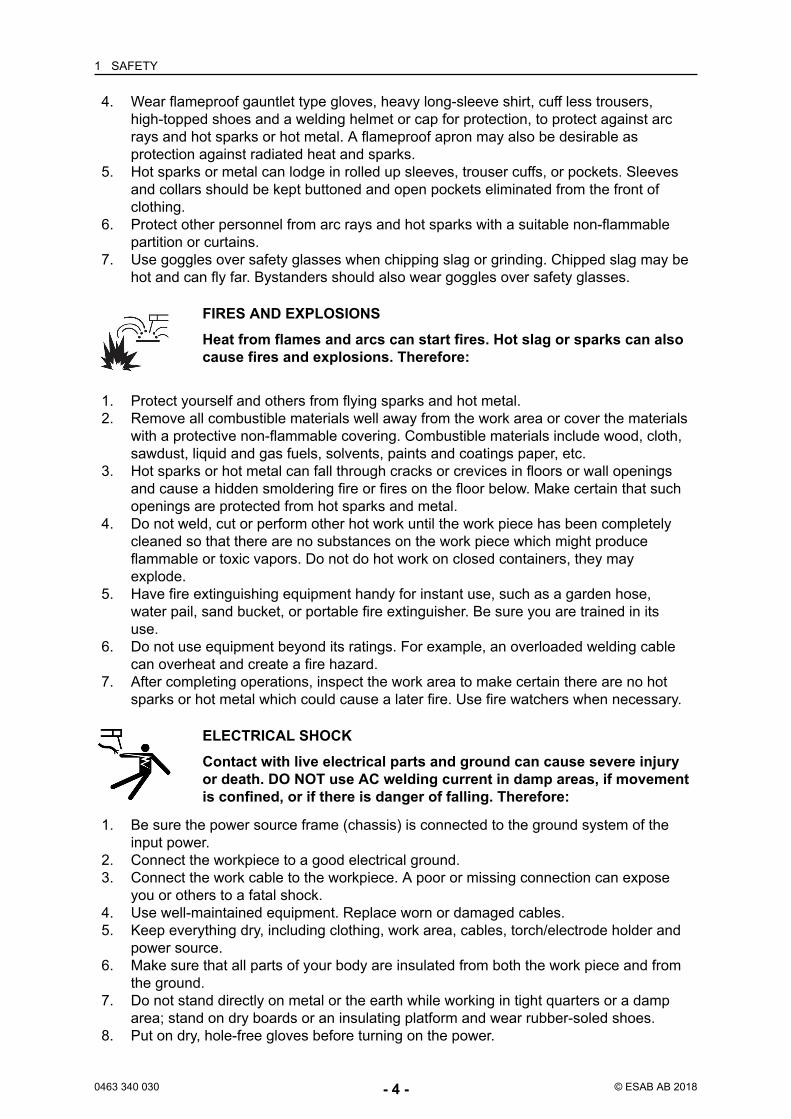
PROTECT YOURSELF AND OTHERSSome welding, cutting and gouging processes are noisy and requireear protection. The arc, like the sun, emits ultraviolet (UV) and otherradiation and can injure skin and eyes. Hot metal can cause burns.Training in the proper use of the processes and equipment is essentialto prevent accidents. Therefore:
1. Wear a welding helmet fitted with a proper shade of filter to protect your face and eyeswhen welding or watching.
2. Always wear safety glasses with side shields in any work area, even if weldinghelmets face shields and goggles are also required.
3. Use a face shield fitted with the correct filter and cover plates to protect your eyes,face, neck and ears from sparks and rays of the arc when operating or observingoperations. Warn bystanders not to watch the arc and not to expose themselves to therays of the electric-arc or hot metal.
1 SAFETY
0463 340 030 - 4 - © ESAB AB 2018
4. Wear flameproof gauntlet type gloves, heavy long-sleeve shirt, cuff less trousers,high-topped shoes and a welding helmet or cap for protection, to protect against arcrays and hot sparks or hot metal. A flameproof apron may also be desirable asprotection against radiated heat and sparks.
5. Hot sparks or metal can lodge in rolled up sleeves, trouser cuffs, or pockets. Sleevesand collars should be kept buttoned and open pockets eliminated from the front ofclothing.
6. Protect other personnel from arc rays and hot sparks with a suitable non-flammablepartition or curtains.
7. Use goggles over safety glasses when chipping slag or grinding. Chipped slag may behot and can fly far. Bystanders should also wear goggles over safety glasses.
FIRES AND EXPLOSIONSHeat from flames and arcs can start fires. Hot slag or sparks can alsocause fires and explosions. Therefore:
1. Protect yourself and others from flying sparks and hot metal.2. Remove all combustible materials well away from the work area or cover the materials
with a protective non-flammable covering. Combustible materials include wood, cloth,sawdust, liquid and gas fuels, solvents, paints and coatings paper, etc.
3. Hot sparks or hot metal can fall through cracks or crevices in floors or wall openingsand cause a hidden smoldering fire or fires on the floor below. Make certain that suchopenings are protected from hot sparks and metal.
4. Do not weld, cut or perform other hot work until the work piece has been completelycleaned so that there are no substances on the work piece which might produceflammable or toxic vapors. Do not do hot work on closed containers, they mayexplode.
5. Have fire extinguishing equipment handy for instant use, such as a garden hose,water pail, sand bucket, or portable fire extinguisher. Be sure you are trained in itsuse.
6. Do not use equipment beyond its ratings. For example, an overloaded welding cablecan overheat and create a fire hazard.
7. After completing operations, inspect the work area to make certain there are no hotsparks or hot metal which could cause a later fire. Use fire watchers when necessary.
ELECTRICAL SHOCKContact with live electrical parts and ground can cause severe injuryor death. DO NOT use AC welding current in damp areas, if movementis confined, or if there is danger of falling. Therefore:
1. Be sure the power source frame (chassis) is connected to the ground system of theinput power.
2. Connect the workpiece to a good electrical ground.3. Connect the work cable to the workpiece. A poor or missing connection can expose
you or others to a fatal shock.4. Use well-maintained equipment. Replace worn or damaged cables.5. Keep everything dry, including clothing, work area, cables, torch/electrode holder and
power source.6. Make sure that all parts of your body are insulated from both the work piece and from
the ground.7. Do not stand directly on metal or the earth while working in tight quarters or a damp
area; stand on dry boards or an insulating platform and wear rubber-soled shoes.8. Put on dry, hole-free gloves before turning on the power.
1 SAFETY
0463 340 030 - 5 - © ESAB AB 2018
9. Turn off the power before removing your gloves.10. Refer to ANSI/ASC Standard Z49.1 for specific grounding recommendations. Do not
mistake the work lead for a ground cable.
ELECTRIC AND MAGNETIC FIELDSMay be dangerous. Electric current flowing through any conductorcauses localized Electric and Magnetic Fields (EMF). Welding andcutting current creates EMF around welding cables and weldingmachines. Therefore:
1. Welders having pacemakers should consult their physician before welding. EMF mayinterfere with some pacemakers.
2. Exposure to EMF may have other health effects which are unknown.3. Welders should use the following procedures to minimise exposure to EMF:
a) Route the electrode and work cables together. Secure them with tape whenpossible.
b) Never coil the torch or work cable around your body.c) Do not place your body between the torch and work cables. Route cables on
the same side of your body.d) Connect the work cable to the workpiece as close as possible to the area being
welded.e) Keep welding power source and cables as far away from your body as
possible.
FUMES AND GASESFumes and gases, can cause discomfort or harm, particularly inconfined spaces. Shielding gases can cause asphyxiation. Therfore:
1. Keep your head out of the fumes. Do not breathe the fumes and gases.2. Always provide adequate ventilation in the work area by natural or mechanical means.
Do not weld, cut or gouge on materials such as galvanized steel, stainless steel,copper, zinc, lead beryllium or cadmium unless positive mechanical ventilation isprovided. Do not breathe fumes from these materials.
3. Do not operate near degreasing and spraying operations. The heat or arc can reactwith chlorinated hydrocarbon vapors to form phosgene, a highly toxic gas and otherirritant gases.
4. If you develop momentary eye, nose or throat irritation while operating, this is anindication that ventilation is not adequate. Stop work and take necessary steps toimprove ventilation in the work area. Do not continue to operate if physical discomfortpersists.
5. Refer to ANSI/ASC Standard Z49.1 for specific ventilation recommendations.6. WARNING: This product when used for welding or cutting, produces fumes or gases
which contain chemicals known to the State of California to cause birth defects and insome cases cancer (California Health & Safety Code §25249.5 et seq.)
CYLINDER HANDLINGCylinders, if mishandled, can rupture and violently release gas. Asudden rupture of cylinder valve or relief device can injure or kill.Therefore:
1 SAFETY
0463 340 030 - 6 - © ESAB AB 2018
1. Locate cylinders away from heat, sparks and flames. Never strike an arc on a cylinder.2. Use the proper gas for the process and use the proper pressure reducing regulator
designed to operate from the compressed gas cylinder. Do not use adaptors. Maintainhoses and fittings in good condition. Follow manufacturer's operating instructions formounting regulator to a compressed gas cylinder.
3. Always secure cylinders in an upright position by chain or strap to suitable handtrucks, undercarriages, benches, wall, post or racks. Never secure cylinders to worktables or fixtures where they may become part of an electrical circuit.
4. When not in use, keep cylinder valves closed. Have valve protection cap in place ifregulator is not connected. Secure and move cylinders by using suitable hand trucks.
MOVING PARTSMoving parts, such as fans, rotors and belts can causeinjury. Therefore:
1. Keep all doors, panels, guards and covers closed and securely in place.2. Stop engine or drive systems before installing or connecting unit.3. Have only qualified people remove covers for maintenance and troubleshooting as
necessary4. To prevent accidental starting of equipment during service, disconnect negative (-)
battery cable from battery.5. Keep hands, hair, loose clothing and tools away from moving parts.6. Reinstall panels or covers and close doors when service is finished and before
starting engine.
WARNING!FALLING EQUIPMENT CAN INJURE
• Only use lifting eye to lift unit. Do NOT use running gear, gas cylinders orany other accessories.
• Use equipment of adequate capacity to lift and support unit.• If using lift forks to move unit, be sure forks are long enough to extend
beyond opposite side of unit.• Keep cables and cords away from moving vehicles when working from an
aerial location.
1 SAFETY
0463 340 030 - 7 - © ESAB AB 2018
WARNING!EQUIPMENT MAINTENANCEFaulty or improperly maintained equipment can cause injury or death.Therefore:
1. Always have qualified personnel perform the installation,troubleshooting and maintenance work. Do not perform any electricalwork unless you are qualified to perform such work.
2. Before performing any maintenance work inside a power source,disconnect the power source from the incoming electrical power.
3. Maintain cables, earthing wire, connections, power cord and powersupply in safe working order. Do not operate any equipment in faultycondition.
4. Do not abuse any equipment or accessories. Keep equipment awayfrom heat sources such as furnaces, wet conditions such as waterpuddles, oil or grease, corrosive atmospheres and inclement weather.
5. Keep all safety devices and cabinet covers in position and in goodrepair.
6. Use equipment only for its intended purpose. Do not modify it in anymanner.
CAUTION!ADDITIONAL SAFETY INFORMATIONFor more information on safe practices for electric arc welding and cuttingequipment, ask your supplier for a copy of “Precautions and Safe Practicesfor Arc Welding, Cutting and Gouging”, Form 52-529.The following publications are recommended to you:
1. ANSI/ASC Z49.1 - “Safety in Welding and Cutting”2. AWS C5.5 - “Recommended Practices for Gas Tungsten Arc Welding”3. AWS C5.6 - “Recommended Practices for Gas Metal Arc welding”4. AWS SP - “Safe practices” - Reprint, Welding Handbook5. ANSI/AWS F4.1 - “Recommended Safe Practices for Welding and
Cutting of Containers That Have Held Hazardous Substances”6. OSHA 29 CFR 1910 - "Safety and health standards"7. CSA W117.2 - "Code for safety in welding and cutting"8. NFPA Standard 51B, “Fire Prevention During Welding, Cutting, and
Other Hot Work"9. CGA Standard P-1, “Precautions for Safe Handling of Compressed
Gases in Cylinders”10.
ANSI Z87.1, "Occupational and Educational Personal Eye and FaceProtection Devices"
1.3 User responsibilityUsers of ESAB equipment have the ultimate responsibility for ensuring that anyone whoworks on or near the equipment observes all the relevant safety precautions. Safetyprecautions must meet the requirements that apply to this type of equipment. The followingrecommendations should be observed in addition to the standard regulations that apply tothe workplace.
All work must be carried out by trained personnel well-acquainted with the operation of theequipment. Incorrect operation of the equipment may lead to hazardous situations which canresult in injury to the operator and damage to the equipment.
1 SAFETY
0463 340 030 - 8 - © ESAB AB 2018
1. Anyone who uses the equipment must be familiar with:○ its operation○ location of emergency stops○ its function○ relevant safety precautions○ welding and cutting or other applicable operation of the equipment
2. The operator must ensure that:○ no unauthorised person is stationed within the working area of the equipment
when it is started up○ no-one is unprotected when the arc is struck or work is started with the
equipment3. The workplace must:
○ be suitable for the purpose○ be free from drafts
4. Personal safety equipment:○ Always wear recommended personal safety equipment, such as safety glasses,
flame-proof clothing, safety gloves○ Do not wear loose-fitting items, such as scarves, bracelets, rings, etc., which
could become trapped or cause burns5. General precautions:
○ Make sure the return cable is connected securely○ Work on high voltage equipment may only be carried out by a qualifiedelectrician
○ Appropriate fire extinguishing equipment must be clearly marked and close athand
○ Lubrication and maintenance must not be carried out on the equipment duringoperation
WARNING!Arc welding and cutting can be injurious to yourself and others. Take precautionswhen welding and cutting.
ELECTRIC SHOCK - Can kill• Install and ground the unit in accordance with instruction manual.• Do not touch live electrical parts or electrodes with bare skin, wet gloves or
wet clothing.• Insulate yourself from work and ground.• Ensure your working position is safeELECTRIC AND MAGNETIC FIELDS - Can be dangerous to health
• Welders having pacemakers should consult their physician before welding.EMF may interfere with some pacemakers.
• Exposure to EMF may have other health effects which are unknown.• Welders should use the following procedures to minimize exposure to
EMF:○ Route the electrode and work cables together on the same side of
your body. Secure them with tape when possible. Do not place yourbody between the torch and work cables. Never coil the torch or workcable around your body. Keep welding power source and cables asfar away from your body as possible.
○ Connect the work cable to the workpiece as close as possible to thearea being welded.
1 SAFETY
0463 340 030 - 9 - © ESAB AB 2018
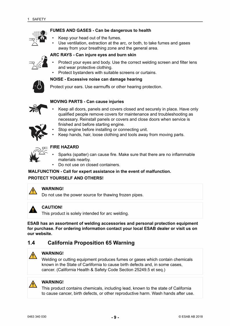
FUMES AND GASES - Can be dangerous to health• Keep your head out of the fumes.• Use ventilation, extraction at the arc, or both, to take fumes and gases
away from your breathing zone and the general area.ARC RAYS - Can injure eyes and burn skin
• Protect your eyes and body. Use the correct welding screen and filter lensand wear protective clothing.
• Protect bystanders with suitable screens or curtains.NOISE - Excessive noise can damage hearingProtect your ears. Use earmuffs or other hearing protection.
MOVING PARTS - Can cause injuries• Keep all doors, panels and covers closed and securely in place. Have only
qualified people remove covers for maintenance and troubleshooting asnecessary. Reinstall panels or covers and close doors when service isfinished and before starting engine.
• Stop engine before installing or connecting unit.• Keep hands, hair, loose clothing and tools away from moving parts.
FIRE HAZARD• Sparks (spatter) can cause fire. Make sure that there are no inflammable
materials nearby.• Do not use on closed containers.
MALFUNCTION - Call for expert assistance in the event of malfunction.PROTECT YOURSELF AND OTHERS!
WARNING!Do not use the power source for thawing frozen pipes.
CAUTION!This product is solely intended for arc welding.
ESAB has an assortment of welding accessories and personal protection equipmentfor purchase. For ordering information contact your local ESAB dealer or visit us onour website.
1.4 California Proposition 65 Warning
WARNING!Welding or cutting equipment produces fumes or gases which contain chemicalsknown in the State of Carlifornia to cause birth defects and, in some cases,cancer. (California Health & Safety Code Section 25249.5 et seq.)
WARNING!This product contains chemicals, including lead, known to the state of Californiato cause cancer, birth defects, or other reproductive harm. Wash hands after use.
2 INTRODUCTION
0463 340 030 - 10 - © ESAB AB 2018
2 INTRODUCTION2.1 OverviewThe Warrior 400i CC/CV and Warrior 500i CC/CV are welding power sources intended forMIG/MAG welding, as well as for welding with powder filled cored wire (FCAW-S), for TIGwelding, for welding with coated electrodes (MMA) and for arc air gouging.
The power sources are intended for use with the following wire feed units:
• Warrior Feed 304• Warrior Feed 304w
ESAB accessories for the product can be found in the "ACCESSORIES" chapter ofthis manual.
2.2 EquipmentThe power sources are supplied with:
• 5 m return cable with earth clamp• 3 m mains cable• instruction manual
3 TECHNICAL DATA
0463 340 030 - 11 - © ESAB AB 2018
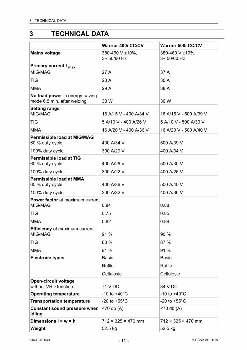
3 TECHNICAL DATAWarrior 400i CC/CV Warrior 500i CC/CV
Mains voltage 380-460 V ±10%,3~ 50/60 Hz
380-460 V ±10%,3~ 50/60 Hz
Primary current I maxMIG/MAG
TIG
MMA
27 A
23 A
29 A
37 A
30 A
38 ANo-load power in energy-savingmode 6.5 min. after welding 30 W 30 WSetting rangeMIG/MAG
TIG
MMA
16 A/15 V - 400 A/34 V
5 A/10 V - 400 A/26 V
16 A/20 V - 400 A/36 V
16 A/15 V - 500 A/39 V
5 A/10 V - 500 A/30 V
16 A/20 V - 500 A/40 VPermissible load at MIG/MAG60 % duty cycle
100% duty cycle
400 A/34 V
300 A/29 V
500 A/39 V
400 A/34 VPermissible load at TIG60 % duty cycle
100% duty cycle
400 A/26 V
300 A/22 V
500 A/30 V
400 A/26 VPermissible load at MMA60 % duty cycle
100% duty cycle
400 A/36 V
300 A/32 V
500 A/40 V
400 A/36 VPower factor at maximum currentMIG/MAG
TIG
MMA
0.84
0.75
0.82
0.88
0.85
0.88Efficiency at maximum currentMIG/MAG
TIG
MMA
91 %
88 %
91 %
90 %
87 %
91 %Electrode types Basic
Rutile
Cellulosic
Basic
Rutile
CellulosicOpen-circuit voltagewithout VRD function 71 V DC 84 V DCOperating temperature -10 to +40°C -10 to +40°CTransportation temperature -20 to +55°C -20 to +55°CConstant sound pressure whenidling
<70 db (A) <70 db (A)
Dimensions l × w × h 712 × 325 × 470 mm 712 × 325 × 470 mmWeight 52.5 kg 52.5 kg
3 TECHNICAL DATA
0463 340 030 - 12 - © ESAB AB 2018
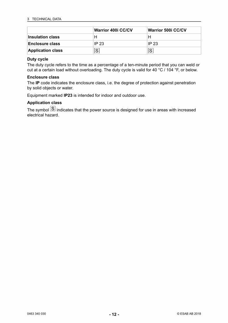
Warrior 400i CC/CV Warrior 500i CC/CVInsulation class H HEnclosure class IP 23 IP 23Application class
Duty cycleThe duty cycle refers to the time as a percentage of a ten-minute period that you can weld orcut at a certain load without overloading. The duty cycle is valid for 40 °C / 104 °F, or below.
Enclosure classThe IP code indicates the enclosure class, i.e. the degree of protection against penetrationby solid objects or water.
Equipment marked IP23 is intended for indoor and outdoor use.
Application classThe symbol indicates that the power source is designed for use in areas with increasedelectrical hazard.
4 INSTALLATION
0463 340 030 - 13 - © ESAB AB 2018
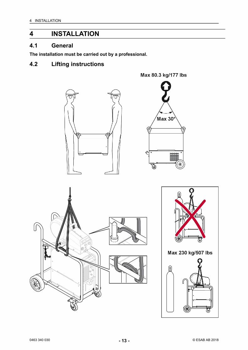
4 INSTALLATION4.1 GeneralThe installation must be carried out by a professional.
4.2 Lifting instructions
4 INSTALLATION
0463 340 030 - 14 - © ESAB AB 2018
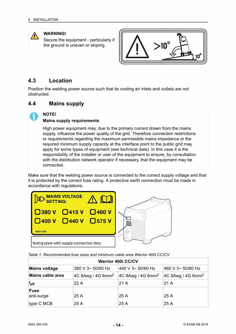
WARNING!Secure the equipment - particularly ifthe ground is uneven or sloping.
4.3 LocationPosition the welding power source such that its cooling air inlets and outlets are notobstructed.
4.4 Mains supply
NOTE!Mains supply requirementsHigh power equipment may, due to the primary current drawn from the mainssupply, influence the power quality of the grid. Therefore connection restrictionsor requirements regarding the maximum permissible mains impedance or therequired minimum supply capacity at the interface point to the public grid mayapply for some types of equipment (see technical data). In this case it is theresponsibility of the installer or user of the equipment to ensure, by consultationwith the distribution network operator if necessary, that the equipment may beconnected.
Make sure that the welding power source is connected to the correct supply voltage and thatit is protected by the correct fuse rating. A protective earth connection must be made inaccordance with regulations.
Warrior 400i CC/CVMains voltage 380 V 3~ 50/60 Hz 440 V 3~ 50/60 Hz 460 V 3~ 50/60 HzMains cable area 4C 8Awg / 4G 6mm2 4C 8Awg / 4G 6mm2 4C 8Awg / 4G 6mm2
Ieff 22 A 21 A 21 AFuseanti-surge
type C MCB
25 A
25 A
25 A
25 A
25 A
25 A
Table 1. Recommended fuse sizes and minimum cable area Warrior 400i CC/CV
4 INSTALLATION
0463 340 030 - 15 - © ESAB AB 2018
Warrior 500i CC/CVMains voltage 380 V 3~ 50/60 Hz 440 V 3~ 50/60 Hz 460 V 3~ 50/60 HzMains cable area 4C Awg / 4G 6mm2 4C 8Awg / 4G 6mm2 4C 8Awg / 4G 6mm2
Ieff 29 A 27 A 26 AFuseanti-surge
type C MCB
35 A
32 A
35 A
32 A
35 A
32 A
Table 2. Recommended fuse sizes and minimum cable area Warrior 500i CC/CV
NOTE!The mains cable areas and fuse sizes as shown above are in accordance withSwedish regulations. Use the power source in accordance with the relevantnational regulations.
Supply from power generatorsThe power source can be supplied from different types of generators. However, somegenerators may not provide sufficient power for the welding power source to operatecorrectly. Generators with Automatic Voltage Regulation (AVR) or with equivalent or bettertype of regulation, with rated power ≥40 kW, are recommended.
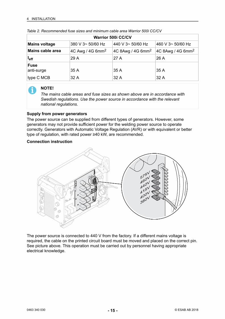
Connection instruction
The power source is connected to 440 V from the factory. If a different mains voltage isrequired, the cable on the printed circuit board must be moved and placed on the correct pin.See picture above. This operation must be carried out by personnel having appropriateelectrical knowledge.

4 INSTALLATION
0463 340 030 - 16 - © ESAB AB 2018
Installation of mains cable
A mains cable needs to be installed, it is then important that the earth connection to thebottom plate must be made in a correct way. See the picture above for the order in which thewashers, nuts and screws are placed.
5 OPERATION
0463 340 030 - 17 - © ESAB AB 2018
5 OPERATION5.1 OverviewGeneral safety regulations for handling the equipment can be found in the chapter"Safety". Read it through before you start the equipment.
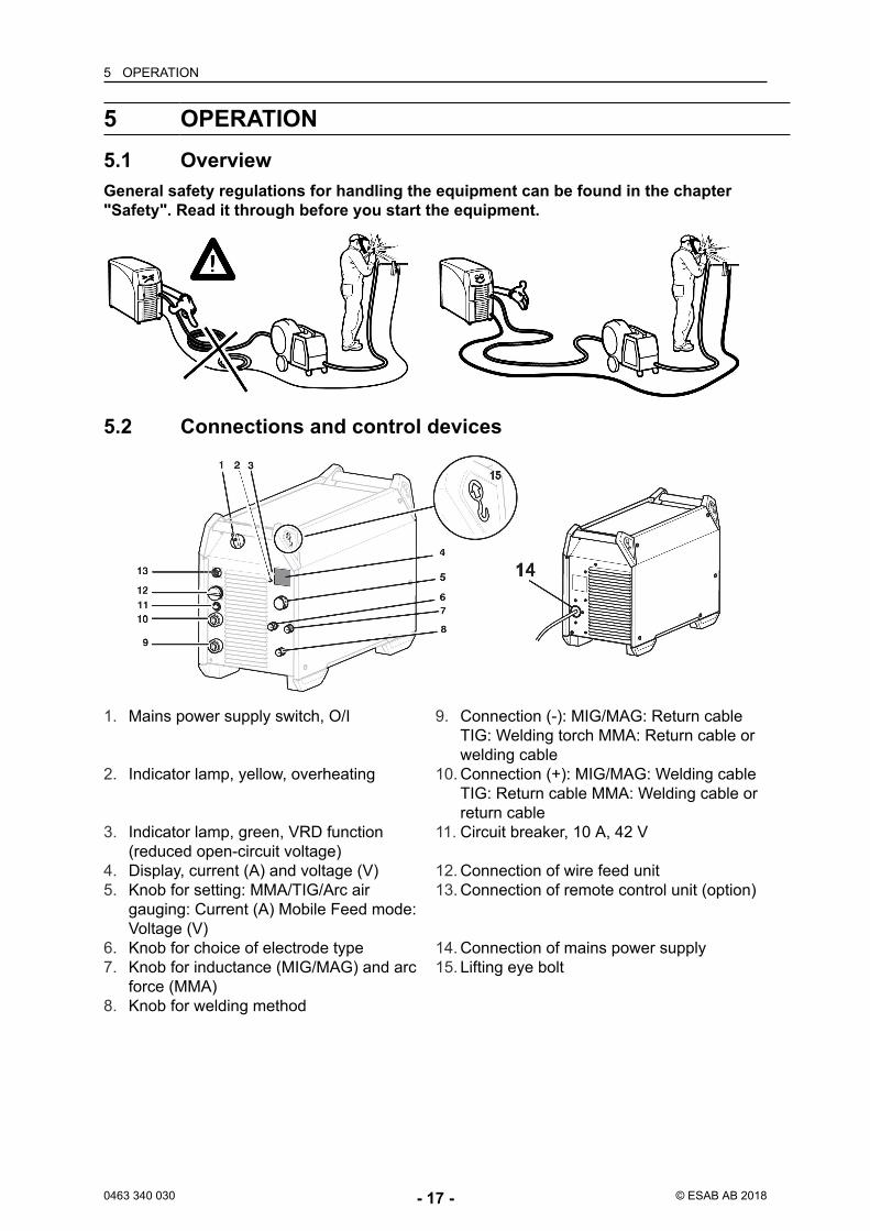
5.2 Connections and control devices
1. Mains power supply switch, O/I 9. Connection (-): MIG/MAG: Return cableTIG: Welding torch MMA: Return cable orwelding cable
2. Indicator lamp, yellow, overheating 10. Connection (+): MIG/MAG: Welding cableTIG: Return cable MMA: Welding cable orreturn cable
3. Indicator lamp, green, VRD function(reduced open-circuit voltage)
11. Circuit breaker, 10 A, 42 V
4. Display, current (A) and voltage (V) 12. Connection of wire feed unit5. Knob for setting: MMA/TIG/Arc air
gauging: Current (A) Mobile Feed mode:Voltage (V)
13. Connection of remote control unit (option)
6. Knob for choice of electrode type 14. Connection of mains power supply7. Knob for inductance (MIG/MAG) and arc
force (MMA)15. Lifting eye bolt
8. Knob for welding method
5 OPERATION
0463 340 030 - 18 - © ESAB AB 2018
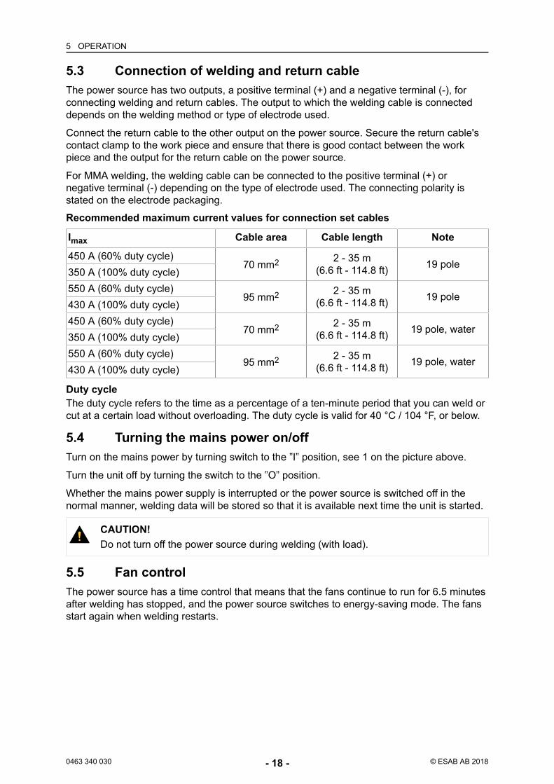
5.3 Connection of welding and return cableThe power source has two outputs, a positive terminal (+) and a negative terminal (-), forconnecting welding and return cables. The output to which the welding cable is connecteddepends on the welding method or type of electrode used.
Connect the return cable to the other output on the power source. Secure the return cable'scontact clamp to the work piece and ensure that there is good contact between the workpiece and the output for the return cable on the power source.
For MMA welding, the welding cable can be connected to the positive terminal (+) ornegative terminal (-) depending on the type of electrode used. The connecting polarity isstated on the electrode packaging.
Recommended maximum current values for connection set cables
Imax Cable area Cable length Note
450 A (60% duty cycle)70 mm2 2 - 35 m
(6.6 ft - 114.8 ft) 19 pole350 A (100% duty cycle)550 A (60% duty cycle)
95 mm2 2 - 35 m(6.6 ft - 114.8 ft) 19 pole
430 A (100% duty cycle)450 A (60% duty cycle)
70 mm2 2 - 35 m(6.6 ft - 114.8 ft) 19 pole, water
350 A (100% duty cycle)550 A (60% duty cycle)
95 mm2 2 - 35 m(6.6 ft - 114.8 ft) 19 pole, water
430 A (100% duty cycle)
Duty cycleThe duty cycle refers to the time as a percentage of a ten-minute period that you can weld orcut at a certain load without overloading. The duty cycle is valid for 40 °C / 104 °F, or below.
5.4 Turning the mains power on/offTurn on the mains power by turning switch to the ”I” position, see 1 on the picture above.
Turn the unit off by turning the switch to the ”O” position.
Whether the mains power supply is interrupted or the power source is switched off in thenormal manner, welding data will be stored so that it is available next time the unit is started.
CAUTION!Do not turn off the power source during welding (with load).
5.5 Fan controlThe power source has a time control that means that the fans continue to run for 6.5 minutesafter welding has stopped, and the power source switches to energy-saving mode. The fansstart again when welding restarts.
5 OPERATION
0463 340 030 - 19 - © ESAB AB 2018
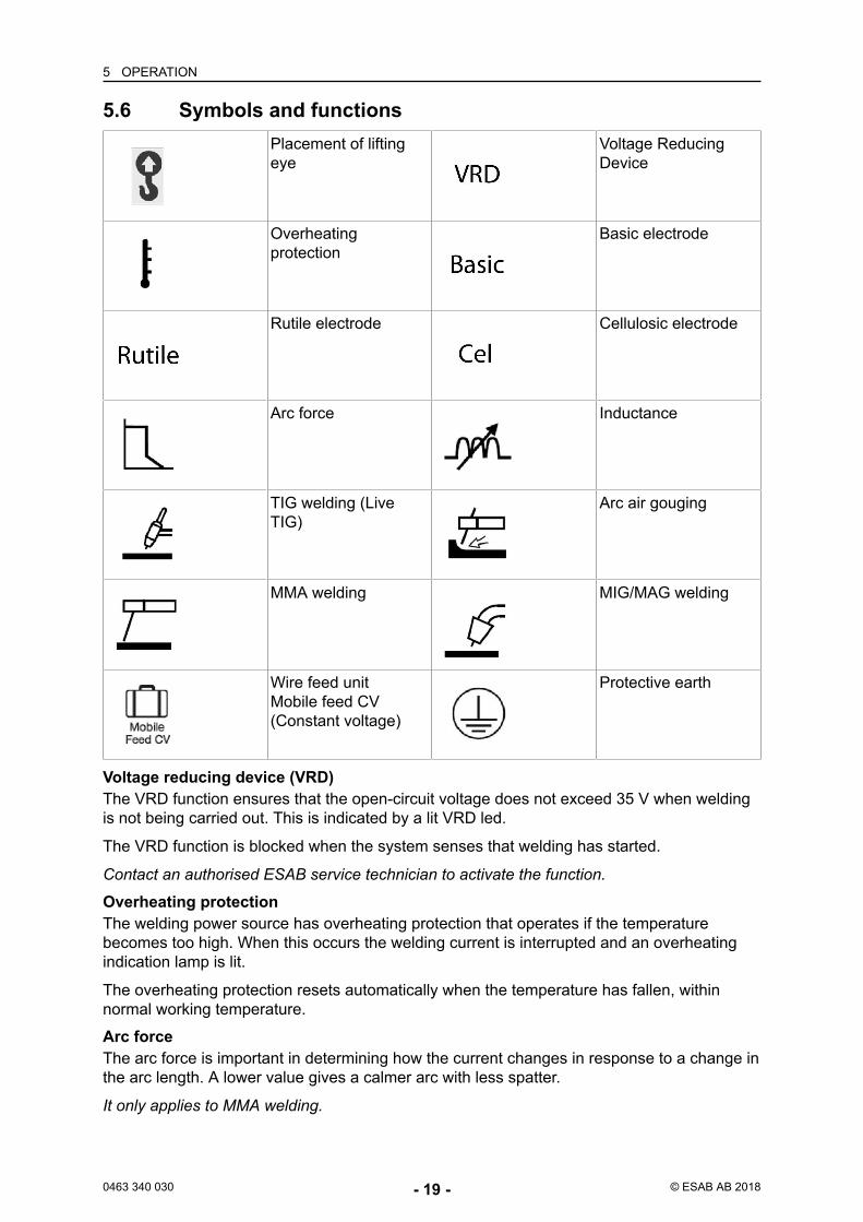
5.6 Symbols and functionsPlacement of liftingeye
Voltage ReducingDevice
Overheatingprotection
Basic electrode
Rutile electrode Cellulosic electrode
Arc force Inductance
TIG welding (LiveTIG)
Arc air gouging
MMA welding MIG/MAG welding
Wire feed unitMobile feed CV(Constant voltage)
Protective earth
Voltage reducing device (VRD)The VRD function ensures that the open-circuit voltage does not exceed 35 V when weldingis not being carried out. This is indicated by a lit VRD led.
The VRD function is blocked when the system senses that welding has started.
Contact an authorised ESAB service technician to activate the function.
Overheating protectionThe welding power source has overheating protection that operates if the temperaturebecomes too high. When this occurs the welding current is interrupted and an overheatingindication lamp is lit.
The overheating protection resets automatically when the temperature has fallen, withinnormal working temperature.
Arc forceThe arc force is important in determining how the current changes in response to a change inthe arc length. A lower value gives a calmer arc with less spatter.
It only applies to MMA welding.
5 OPERATION
0463 340 030 - 20 - © ESAB AB 2018
InductanceHigher inductance results in a wider weld pool and less spatter. Lower inductance producesa harsher sound but a stable, concentrated arc.
It only applies to MIG/MAG welding.
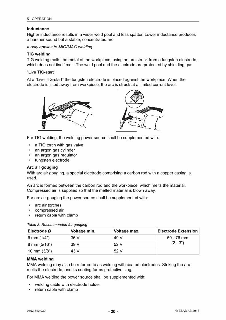
TIG weldingTIG welding melts the metal of the workpiece, using an arc struck from a tungsten electrode,which does not itself melt. The weld pool and the electrode are protected by shielding gas.
"Live TIG-start"
At a ”Live TIG-start” the tungsten electrode is placed against the workpiece. When theelectrode is lifted away from workpiece, the arc is struck at a limited current level.
For TIG welding, the welding power source shall be supplemented with:
• a TIG torch with gas valve• an argon gas cylinder• an argon gas regulator• tungsten electrode
Arc air gougingWith arc air gouging, a special electrode comprising a carbon rod with a copper casing isused.
An arc is formed between the carbon rod and the workpiece, which melts the material.Compressed air is supplied so that the melted material is blown away.
For arc air gouging the power source shall be supplemented with:
• arc air torches• compressed air• return cable with clamp
Electrode Ø Voltage min. Voltage max. Electrode Extension6 mm (1/4") 36 V 49 V 50 - 76 mm
(2 - 3")8 mm (5/16") 39 V 52 V10 mm (3/8") 43 V 52 V
Table 3. Recommended for gouging
MMA weldingMMA welding may also be referred to as welding with coated electrodes. Striking the arcmelts the electrode, and its coating forms protective slag.
For MMA welding the power source shall be supplemented with:
• welding cable with electrode holder• return cable with clamp

5 OPERATION
0463 340 030 - 21 - © ESAB AB 2018
MIG/MAG and self shielded cored wire weldingAn arc melts a continuously supplied wire. The weld pool is protected by shielding gas.
For MIG/MAG and self shielded core wire welding, the power source shall be supplementedwith:
• wire feed unit• welding torch• connection cable between power source and wire feed unit• gas cylinder• return cable with clamp
6 MAINTENANCE
0463 340 030 - 22 - © ESAB AB 2018
6 MAINTENANCE6.1 OverviewRegular maintenance is important for safe, reliable operation.
Only personnel with the appropriate electrical skills (authorized staff) may remove safetyplates.
CAUTION!All warranty undertakings from the supplier cease to apply if the customerattempts any work to rectify any faults in the product during the warranty period.
6.2 Power sourceTo maintain the performance and increase the lifetime of the power source it is mandatory toclean the product regularly. How often depends on:
• the welding process• the arc time• the working environment• the surrounding environment, that is grinding etc.
Tools needed for the cleaning procedure:
• torx screwdriver, T25 and T30• dry compressed air at a pressure of 4 bar• protective equipment like ear plugs, safety glasses, masks, gloves and safety shoes
CAUTION!Make sure that the cleaning procedure is done in a suitable prepared workspace.
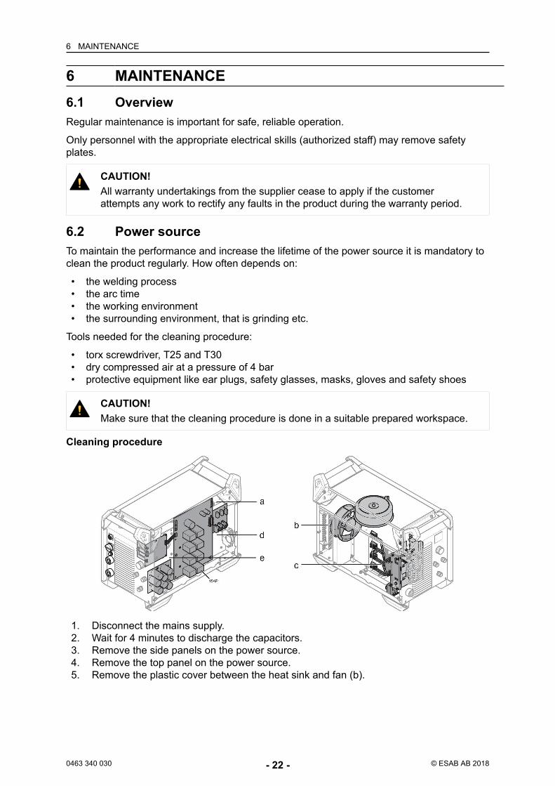
Cleaning procedure
1. Disconnect the mains supply.2. Wait for 4 minutes to discharge the capacitors.3. Remove the side panels on the power source.4. Remove the top panel on the power source.5. Remove the plastic cover between the heat sink and fan (b).
6 MAINTENANCE
0463 340 030 - 23 - © ESAB AB 2018
6. Clean the power source with dry compressed air (4 bar) as follows:a) The upper rear part.b) From the rear panel through the secondary heat sink.c) The inductor, transformer and current sensor.d) The power components side, from the rear side behind PCB 15AP1.e) The PCBs at both sides.
7. Make sure that there is no dust left on any part.8. Install the plastic cover between the heat sink and the fan (2) and make sure it is
correctly fitted against the heat sink.9. Do a test of the power source according to IEC 60974-4, follow the procedure in
section "After repair, inspection and test" in the Service manual.10. Install the top panel on the power source.11. Install the side panels on the power source.12. Connect the mains supply.
6.3 Welding torchA regular programme of care and maintenance reduces unnecessary and expensivedowntime.
Each time a wire bobbin is changed, the welding torch should be removed from the powersource and blown clean with compressed air.
The wire end must not have sharp edges when inserted into the wire liner.
For detailed information see instruction manuals for welding torches.
7 TROUBLESHOOTING
0463 340 030 - 24 - © ESAB AB 2018
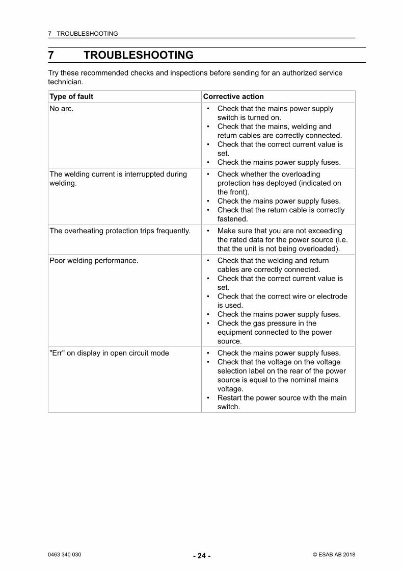
7 TROUBLESHOOTINGTry these recommended checks and inspections before sending for an authorized servicetechnician.
Type of fault Corrective actionNo arc. • Check that the mains power supply
switch is turned on.• Check that the mains, welding and
return cables are correctly connected.• Check that the correct current value is
set.• Check the mains power supply fuses.
The welding current is interruppted duringwelding.
• Check whether the overloadingprotection has deployed (indicated onthe front).
• Check the mains power supply fuses.• Check that the return cable is correctly
fastened.The overheating protection trips frequently. • Make sure that you are not exceeding
the rated data for the power source (i.e.that the unit is not being overloaded).
Poor welding performance. • Check that the welding and returncables are correctly connected.
• Check that the correct current value isset.
• Check that the correct wire or electrodeis used.
• Check the mains power supply fuses.• Check the gas pressure in the
equipment connected to the powersource.
"Err" on display in open circuit mode • Check the mains power supply fuses.• Check that the voltage on the voltage
selection label on the rear of the powersource is equal to the nominal mainsvoltage.
• Restart the power source with the mainswitch.
8 ORDERING SPARE PARTS
0463 340 030 - 25 - © ESAB AB 2018
8 ORDERING SPARE PARTS
CAUTION!Repair and electrical work should be performed by an authorised ESAB servicetechnician. Use only ESAB original spare and wear parts.
Warrior 400i CC/CV and Warrior 500i CC/CV are designed and tested in accordance withthe international standards IEC 60974-1. On completion of service or repair work, it is theresponsibility of the person(s) performing the work to ensure that the product still complieswith the requirements of the above standards.
Spare parts and wear parts can be ordered through your nearest ESAB dealer, seeesab.com. When ordering, please state product type, serial number, designation and sparepart number in accordance with the spare parts list. This facilitates dispatch and ensurescorrect delivery.
DIAGRAM
0463 340 030 - 26 - © ESAB AB 2018
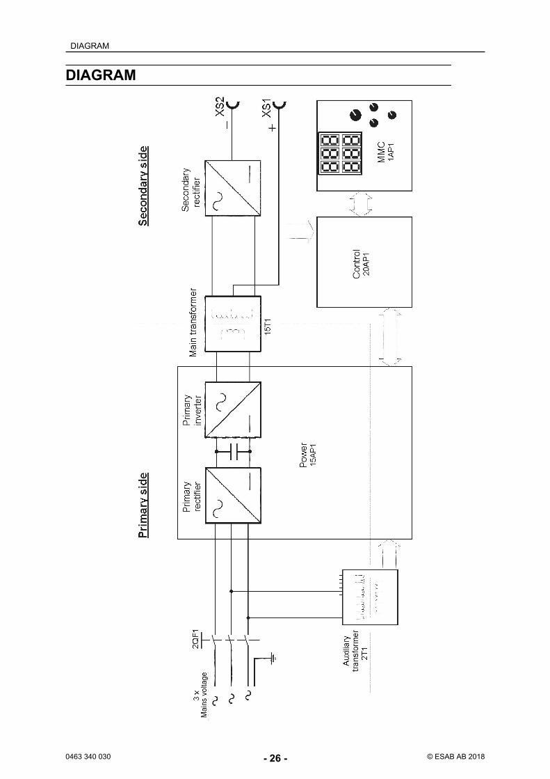
DIAGRAM
ORDERING NUMBERS
0463 340 030 - 27 - © ESAB AB 2018
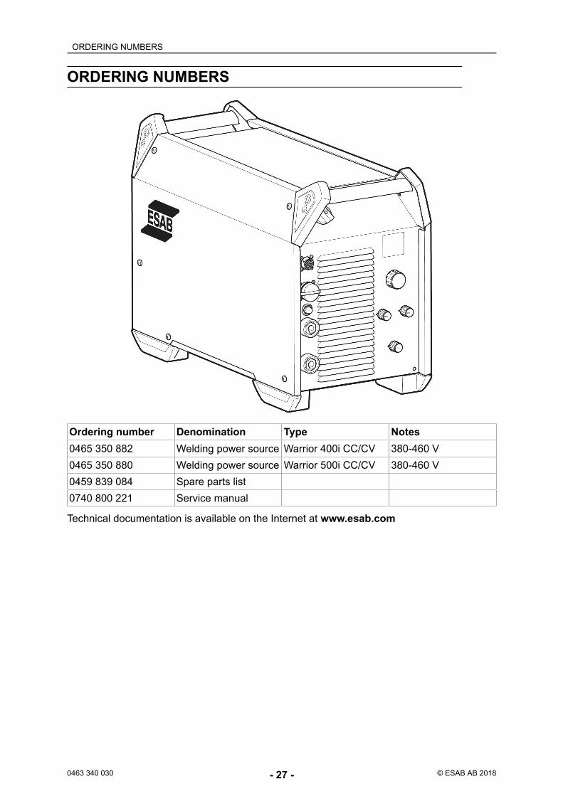
ORDERING NUMBERS
Ordering number Denomination Type Notes0465 350 882 Welding power source Warrior 400i CC/CV 380-460 V0465 350 880 Welding power source Warrior 500i CC/CV 380-460 V0459 839 084 Spare parts list0740 800 221 Service manual
Technical documentation is available on the Internet at www.esab.com
ACCESSORIES
0463 340 030 - 28 - © ESAB AB 2018
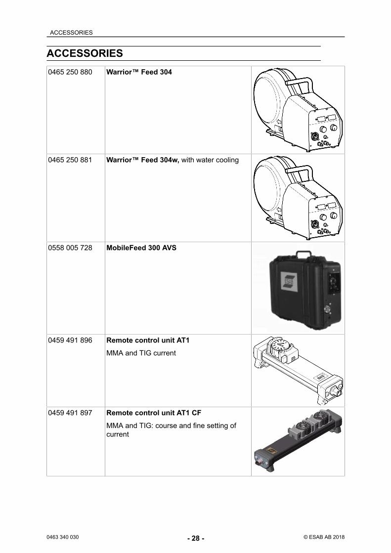
ACCESSORIES0465 250 880 Warrior™ Feed 304
0465 250 881 Warrior™ Feed 304w, with water cooling
0558 005 728 MobileFeed 300 AVS
0459 491 896 Remote control unit AT1MMA and TIG current
0459 491 897 Remote control unit AT1 CFMMA and TIG: course and fine setting ofcurrent
ACCESSORIES
0463 340 030 - 29 - © ESAB AB 2018
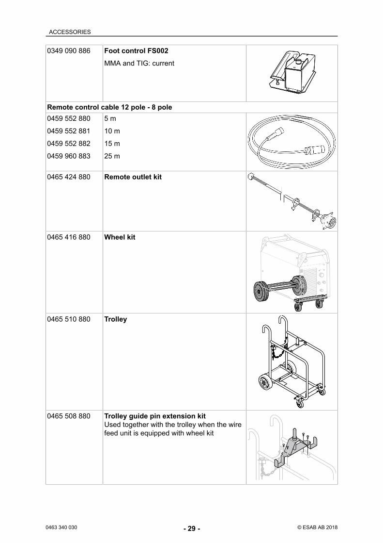
0349 090 886 Foot control FS002MMA and TIG: current
Remote control cable 12 pole - 8 pole0459 552 880
0459 552 881
0459 552 882
0459 960 883
5 m
10 m
15 m
25 m
0465 424 880 Remote outlet kit
0465 416 880 Wheel kit
0465 510 880 Trolley
0465 508 880 Trolley guide pin extension kitUsed together with the trolley when the wirefeed unit is equipped with wheel kit
ACCESSORIES
0463 340 030 - 30 - © ESAB AB 2018
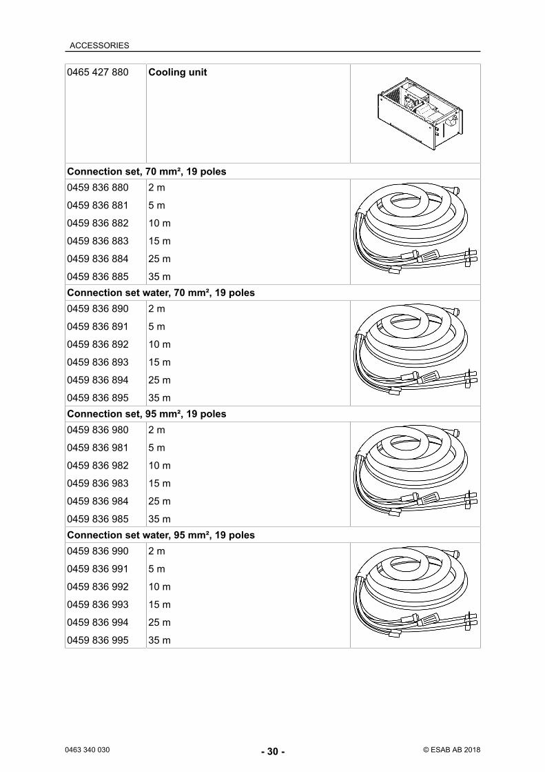
0465 427 880 Cooling unit
Connection set, 70 mm², 19 poles0459 836 880
0459 836 881
0459 836 882
0459 836 883
0459 836 884
0459 836 885
2 m
5 m
10 m
15 m
25 m
35 mConnection set water, 70 mm², 19 poles0459 836 890
0459 836 891
0459 836 892
0459 836 893
0459 836 894
0459 836 895
2 m
5 m
10 m
15 m
25 m
35 mConnection set, 95 mm², 19 poles0459 836 980
0459 836 981
0459 836 982
0459 836 983
0459 836 984
0459 836 985
2 m
5 m
10 m
15 m
25 m
35 mConnection set water, 95 mm², 19 poles0459 836 990
0459 836 991
0459 836 992
0459 836 993
0459 836 994
0459 836 995
2 m
5 m
10 m
15 m
25 m
35 m
ACCESSORIES
0463 340 030 - 31 - © ESAB AB 2018
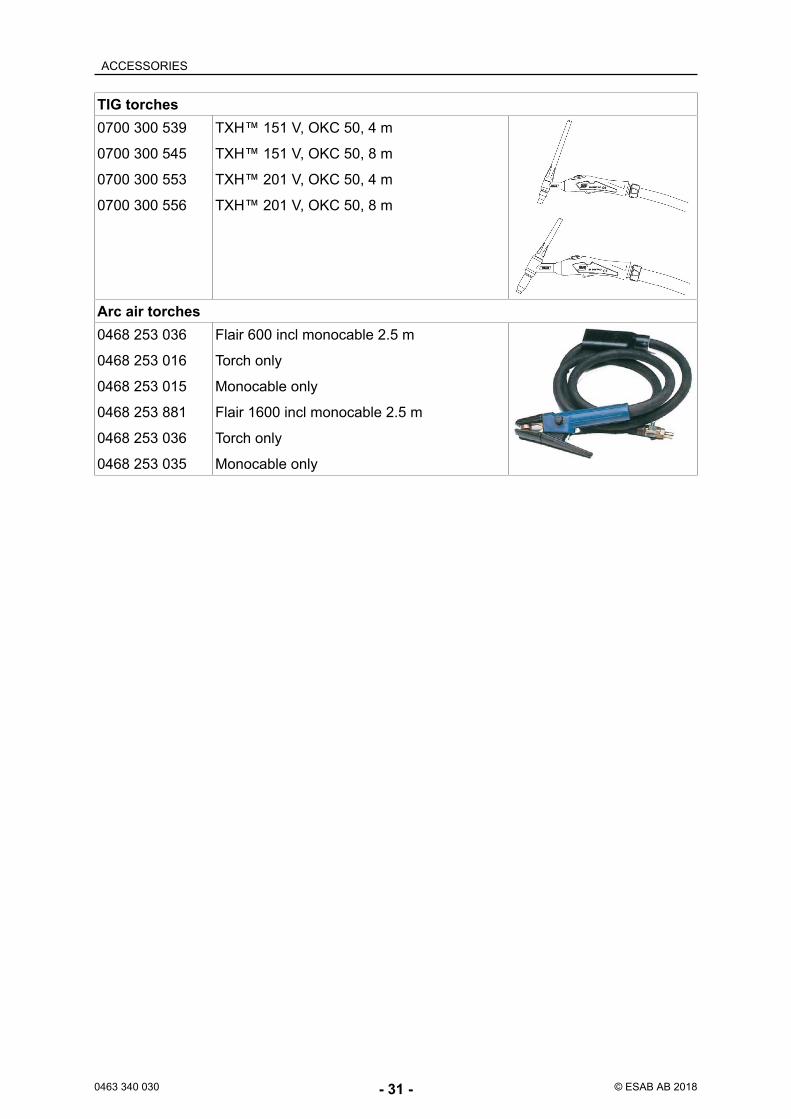
TIG torches0700 300 539
0700 300 545
0700 300 553
0700 300 556
TXH™ 151 V, OKC 50, 4 m
TXH™ 151 V, OKC 50, 8 m
TXH™ 201 V, OKC 50, 4 m
TXH™ 201 V, OKC 50, 8 m
Arc air torches0468 253 036
0468 253 016
0468 253 015
0468 253 881
0468 253 036
0468 253 035
Flair 600 incl monocable 2.5 m
Torch only
Monocable only
Flair 1600 incl monocable 2.5 m
Torch only
Monocable only

For contact information visit esab.comESAB AB, Lindholmsallén 9, Box 8004, 402 77 Gothenburg, Sweden, Phone +46 (0) 31 50 90 00
http://manuals.esab.com