WARNING: If you are unsure of the dangers involved with ... · WARNING: If you are unsure of the...
11
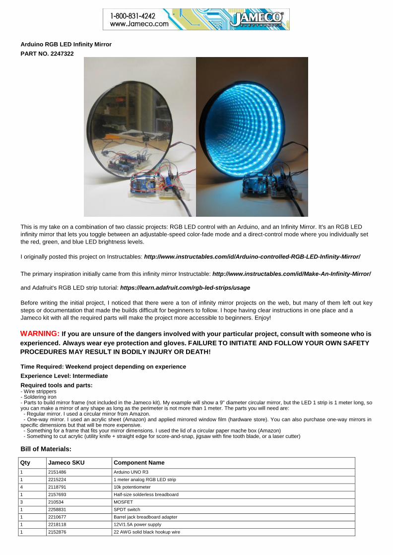
Arduino RGB LED Infinity Mirror PART NO. 2247322 This is my take on a combination of two classic projects: RGB LED control with an Arduino, and an Infinity Mirror. It's an RGB LED infinity mirror that lets you toggle between an adjustable-speed color-fade mode and a direct-control mode where you individually set the red, green, and blue LED brightness levels. I originally posted this project on Instructables: http://www.instructables.com/id/Arduino-controlled-RGB-LED-Infinity-Mirror/ The primary inspiration initially came from this infinity mirror Instructable: http://www.instructables.com/id/Make-An-Infinity-Mirror/ and Adafruit's RGB LED strip tutorial: https://learn.adafruit.com/rgb-led-strips/usage Before writing the initial project, I noticed that there were a ton of infinity mirror projects on the web, but many of them left out key steps or documentation that made the builds difficult for beginners to follow. I hope having clear instructions in one place and a Jameco kit with all the required parts will make the project more accessible to beginners. Enjoy! WARNING: If you are unsure of the dangers involved with your particular project, consult with someone who is experienced. Always wear eye protection and gloves. FAILURE TO INITIATE AND FOLLOW YOUR OWN SAFETY PROCEDURES MAY RESULT IN BODILY INJURY OR DEATH! Time Required: Weekend project depending on experience Experience Level: Intermediate Required tools and parts: - Wire strippers - Soldering iron - Parts to build mirror frame (not included in the Jameco kit). My example will show a 9" diameter circular mirror, but the LED 1 strip is 1 meter long, so you can make a mirror of any shape as long as the perimeter is not more than 1 meter. The parts you will need are: - Regular mirror. I used a circular mirror from Amazon. - One-way mirror. I used an acrylic sheet (Amazon) and applied mirrored window film (hardware store). You can also purchase one-way mirrors in specific dimensions but that will be more expensive. - Something for a frame that fits your mirror dimensions. I used the lid of a circular paper mache box (Amazon) - Something to cut acrylic (utility knife + straight edge for score-and-snap, jigsaw with fine tooth blade, or a laser cutter) Bill of Materials: Qty Jameco SKU Component Name 1 2151486 Arduino UNO R3 1 2215224 1 meter analog RGB LED strip 4 2118791 10k potentiometer 1 2157693 Half-size solderless breadboard 3 210534 MOSFET 1 2258831 SPDT switch 1 2210677 Barrel jack breadboard adapter 1 2218118 12V/1.5A power supply 1 2152876 22 AWG solid black hookup wire
Transcript of WARNING: If you are unsure of the dangers involved with ... · WARNING: If you are unsure of the...
Arduino RGB LED Infinity Mirror
PART NO. 2247322
This is my take on a combination of two classic projects: RGB LED control with an Arduino, and an Infinity Mirror. It's an RGB LED
infinity mirror that lets you toggle between an adjustable-speed color-fade mode and a direct-control mode where you individually set
the red, green, and blue LED brightness levels.
I originally posted this project on Instructables: http://www.instructables.com/id/Arduino-controlled-RGB-LED-Infinity-Mirror/
The primary inspiration initially came from this infinity mirror Instructable: http://www.instructables.com/id/Make-An-Infinity-Mirror/
and Adafruit's RGB LED strip tutorial: https://learn.adafruit.com/rgb-led-strips/usage
Before writing the initial project, I noticed that there were a ton of infinity mirror projects on the web, but many of them left out key
steps or documentation that made the builds difficult for beginners to follow. I hope having clear instructions in one place and a
Jameco kit with all the required parts will make the project more accessible to beginners. Enjoy!
WARNING: If you are unsure of the dangers involved with your particular project, consult with someone who is
experienced. Always wear eye protection and gloves. FAILURE TO INITIATE AND FOLLOW YOUR OWN SAFETY
PROCEDURES MAY RESULT IN BODILY INJURY OR DEATH!
Time Required: Weekend project depending on experience
Experience Level: Intermediate
Required tools and parts: - Wire strippers - Soldering iron - Parts to build mirror frame (not included in the Jameco kit). My example will show a 9" diameter circular mirror, but the LED 1 strip is 1 meter long, so you can make a mirror of any shape as long as the perimeter is not more than 1 meter. The parts you will need are: - Regular mirror. I used a circular mirror from Amazon.
- One-way mirror. I used an acrylic sheet (Amazon) and applied mirrored window film (hardware store). You can also purchase one-way mirrors in specific dimensions but that will be more expensive. - Something for a frame that fits your mirror dimensions. I used the lid of a circular paper mache box (Amazon)
- Something to cut acrylic (utility knife + straight edge for score-and-snap, jigsaw with fine tooth blade, or a laser cutter)
Bill of Materials:
Qty Jameco SKU Component Name
1 2151486 Arduino UNO R3
1 2215224 1 meter analog RGB LED strip
4 2118791 10k potentiometer
1 2157693 Half-size solderless breadboard
3 210534 MOSFET
1 2258831 SPDT switch
1 2210677 Barrel jack breadboard adapter
1 2218118 12V/1.5A power supply
1 2152876 22 AWG solid black hookup wire

Step 1 - How does an infinity mirror work? (Part 1)
The infinity mirror actually contains two mirrors with different transmissivity and reflectivity. For all practical intents and purposes,
mirrors that we deal with in everyday life are 100% reflective (technically a tiny amount of light will also be absorbed, but we can
ignore that for now). That's the regular mirror at the "back" of the infinity mirror (on the left in the diagram above). The tinted window
film, however (on the right in the diagram above), only reflects about half of the light that hits it*. This means that, when you sandwich
an LED between the two mirrors, some of the light escapes through the front mirror and into your eye. The rest is bounced back off
the rear mirror, then into the front mirror again, and this process continues off to infinity - thus the name. But, since a little bit of light
escapes each time, each successive illusionary LED that you see will look a little bit dimmer, until they gradually disappear - you can't
actually see infinitely many LEDs.
*The exact percentages of reflectivity/transmissivity might vary depending on what kind you buy - different levels of reflectivity and
transmissivity are actually regulated in different states for use in car windows, Google it if you're curious.
Step 2 - How does an infinity mirror work? (Part 2)
Note that this does not work because the window tint "only lets light through in one direction", which is a common misconception. In
order for the illusion to work properly, the side of the front mirror the observer is on (the outside world) must be much darker than the
side with the LEDs (inside the infinity mirror). This is the same effect that you see in crime dramas/movies where someone is held in
an interrogation room that has a mirror on the wall, but there are people on the other side of that mirror observing as though it's just a
window. That only works if the interrogation room is well-lit and the observation room is dark.
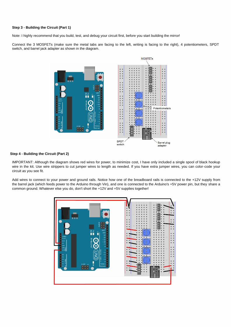
Step 3 - Building the Circuit (Part 1)
Note: I highly recommend that you build, test, and debug your circuit first, before you start building the mirror!
Connect the 3 MOSFETs (make sure the metal tabs are facing to the left, writing is facing to the right), 4 potentiometers, SPDT switch, and barrel jack adapter as shown in the diagram.
Step 4 - Building the Circuit (Part 2)
IMPORTANT: Although the diagram shows red wires for power, to minimize cost, I have only included a single spool of black hookup
wire in the kit. Use wire strippers to cut jumper wires to length as needed. If you have extra jumper wires, you can color-code your
circuit as you see fit.
Add wires to connect to your power and ground rails. Notice how one of the breadboard rails is connected to the +12V supply from
the barrel jack (which feeds power to the Arduino through Vin), and one is connected to the Arduino's +5V power pin, but they share a
common ground. Whatever else you do, don't short the +12V and +5V supplies together!

Step 5 - Building the Circuit (Part 3)
Add wires to connect the Arduino's inputs and outputs as shown in the diagram. Again, I have color-coded here but the kit only
includes black wire.
IMPORTANT: Again, my wiring diagram sticks with the convention that red is for power. I did this originally because some LED strips
just come with solder pads and not pre-attached wires. However, **the LED strip from Jameco comes with pre-attached wires. The
BLACK wire is for +12V, and the red wire is the red LED cathode. Don't get these mixed up!**
Step 6 - Circuit picture
This is just a picture of the assembled circuit.

Step 7 - How does the circuit work?
This is a rough explanation of how the circuit works and what the components are for. Seasoned veterans can skip this step, but read
on if you're curious. Google the names of individual components if you want to learn more about them.
The barrel jack adapter provides a +12V supply to the breadboard. This is required to power the LED strips, and also powers the
Arduino through its Vin pin. Technically, the Arduino's built-in barrel plug will accept a +12V supply, which you can then access
through the Vin pin, but the LEDs draw a lot of current - more than you want running through the Arduino board. This way, the current
"splits up" - the Arduino only draws what it needs, and the high current goes straight to the LEDs through the breadboard. Special
thanks to the Adafruit support forums for helping me figure this out.
The SPDT switch just acts as a toggle to select which "mode" the program is in. The details of the code are explained in the next
step, but essentially it just switches between a "color fade" mode that rotates through different colors, and a direct-control mode
where you control individual red, green, and blue LED brightness. The middle pin of the switch is connected to one of the Arduino's
digital input pins, and the outer two pins are connected to +5V and ground. So, depending on which way the switch is flipped, the
program reads a digital HIGH or LOW using the digitalRead() function and acts accordingly (note: SPDT stands for "single-pole
double-throw", the Wikipedia page on switches has a nice table summarizing the different types of switches, with diagrams).
The potentiometers are your "controls" depending on which mode the program is in. In individual-control mode, the three
potentiometers control brightness of the red, green, and blue LEDs respectively. In color-fade mode, a single potentiometer controls
the speed of the fading. The potentiometers have three pins. Like the switch, one pin is connected to +5V, and one pin to ground.
However, unlike the switch, rotating the potentiometer makes the voltage on the middle pin vary continuously between 0V and 5V,
instead of just toggling between the two. So, the middle pins of the potentiometers are connected to the Arduino's analog inputs.
Then, using the analogRead() function, the Arduino converts that voltage to a number between 0 and 1023 for use in the program
(see next step).
The MOSFETs are probably the trickiest part to understand for a newcomer to electronics. These are required to drive "high power" devices like motors, solenoids and LED strips, which frequently require more current than the Arduino can supply. The Wikipedia page on these is actually rather dense, so I'll try to give a simplified explanation here. The MOSFET has three pins, called the "gate" (G), "drain" (D), and "source" (S). In its simplest form, the MOSFET acts like a valve that lets current flow from the drain to the source. The "gate" controls this valve (think of opening and closing a valve to a garden hose), except that control is electrical instead of mechanical. A voltage applied to the gate from one of the Arduino's output pins turns the MOSFET "on" - allowing high current to flow from the drain to the source, without actually drawing any current from the Arduino. If the voltage to the gate from the Arduino is zero, the MOSFET shuts off and stops current from flowing. This way you can control even enormous motors and lights with a tiny little Arduino, as long as you have an external power supply big enough to handle it.
I should also mention pulse width modulation (PWM). This is a common technique used to control LED brightness with an Arduino.
In short, the Arduino's output pins are digital, so they can only output a HIGH or a LOW (5V or 0V). They can't continuously vary their
voltage to adjust something like LED brightness or motor speed. Instead, what they can do is send out very rapid pulses (roughly 500
times per second with the Arduino), much faster than the human eye can see. Each pulse consists of a HIGH segment and a LOW
segment, and the relative ratio between the two determines the "brightness" that we actually see. A pulse that is 0% high and 100%
low will just look like "off". 100% high and 0% low will be "full brightness", and 50% high/50% low will be about half-brightness. You
get the idea. In this circuit, a PWM signal is sent to the MOSFETs, which then controls the high current going through the LEDs,
allowing a "fading" effect and adjustable brightness.

Step 8 - Arduino code
You can copy the Arduino code from this Instructables step:
http://www.instructables.com/id/Arduino-controlled-RGB-LED-Infinity-Mirror/step4/Arduino-Code/
If this is your first time using an Arduino, check out their official getting started page for instructions on installing their software and
uploading code to the Arduino:
https://www.arduino.cc/en/Guide/HomePage
Step 9 - Test and debug
Plug your power supply into the barrel jack adapter, and after your Arduino takes a second to boot up, you should be able to control
the lights! Use the toggle switch to switch between two modes. In one mode, you can directly the control the red, green, and blue LED
brightness with the first three potentiometers; and combine them to make different colors. In the other mode, the LEDs will fade
between colors automatically, but you can control the speed of the fading with the fourth potentiometer.
Watch this video for a demonstration, and see below for troubleshooting tips if it doesn't work. Notice how there are a couple spots in
this video where my LEDs flicker - this must mean I have a loose connection or two bare wires bumping into each other somewhere
when I jostle the Arduino around. Watch out for that.
https://youtu.be/PL9EvnRBeiQ
Troubleshooting Tips
-Double and triple check your breadboard connections. It only takes one misplaced wire to stop the whole thing from working.
-Make sure the I/O pins assigned in your code match the pins you're actually using. This shouldn't be an issue if you copied and
pasted my code directly, but it can't hurt to check.
-Make sure your LED strip works. Hook the LED strip's V+ wire up directly to the +12V rail on the breadboard, then test red, green, and blue individually by plugging their respective wires into the ground rail. The LED strip has built-in resistors so you don't have to worry about blowing it out. If each color lights up, then your strip is fine, and the problem is elsewhere in your circuit. -Test your circuit and code with regular LEDs, skip the MOSFETs. If MOSFETs are a bit too new and confusing, you can do a starter
version of this project that just uses three plain old LEDs, or a single RGB LED. These are low-current and low-voltage enough that
they can be driven straight from the Arduino and don't require the MOSFETs, but you will need current-limiting resistors so the LEDs
don't burn out. LED blinking and fading are very common starter Arduino projects so I won't reproduce the directions here.
-Skip the potentiometers and test the circuit with a hard-coded color pattern. This lets you make sure the PWM signals and
MOSFETs are working, without having to worry about the analog inputs and potentiometers.
You may have noticed a trend here - the general idea is to break your circuit (or code) down into smaller, isolated sections that can be
tested individually. This lets you narrow things down and search for problems in a compartmentalized way, instead of just staring at a
giant circuit and mess of code and wondering what went wrong. If you can think of other/better ways to debug this circuit, please
chime in in the comments.

Step 10 - Prepare mirror frame
Find or build an enclosure that is slightly larger than the size of your regular mirror. This picture shows the lid of a 9" paper mache box
that fits around a 9" diameter mirror.
Step 11 - Drill hole in frame
You will need to feed the 4 LED wires through the side of your frame. Drill a hole large enough for them. Note that I decided to paint my frame black, which I did before this step.
Step 12 - Mount LED strip
IMPORTANT: the LED strip can be cut to length but only in *3-LED sections*. The sections where you can cut are marked on the
strip. Do not just cut in any location. Once you've cut the strip to length, use the adhesive backing to adhere it around the inner
perimeter of your frame.

Step 13 - Attach mirror
I used hot glue to attach the circular mirror to the circular piece of cardboard that I cut out of the box lid, then used electrical tape to
attach it to the frame and seal around the edges.
Step 14 - Cutting acrylic - Jigsaw
IMPORTANT: Wear your safety glasses if you try this!
I don't really recommend cutting acrylic with a jigsaw as it is brittle and tends to shatter. However, if you use a fine-tooth blade, clamp
tightly, and cut slowly, it can work. If you have access to a laser cutter or can just order acrylic that's the right shape to begin with
(McMaster-Carr sells circular pieces), that might be a lot easier.

Step 15 - Cutting acrylic - score and snap
Another option for cutting the acrylic is to use a score-and-snap method. You can use a utility knife but they also sell special
plastic-cutting knives at hardware stores just for this purpose. This will work much better if you are doing a rectangular mirror. If you
are doing a circular mirror you will need to snap off a ton of individual sections to get the appearance of a rounded edge. Someone
recommended to me that you put the acrylic in the freezer for a few hours, to make it more brittle and easier to snap.
Step 16 - Apply mirror film
Follow the manufacturer's instructions to apply the mirrored window film to the acrylic. Be patient and do this carefully, taking the time
to smooth out any bubbles, as they will affect the final appearance of your mirror.

Step 17 - Mount one-way mirror
Attach the one-way mirror (which you just made by applying the mirrored window film to the acrylic) to the front of the frame, with the
film facing outward. I just used electrical tape.

Step 18 - Enjoy!
Boot up your Arduino and enjoy your new infinity mirror! As long as you tested and debugged your circuit before assembling the
mirror, you shouldn't have any major problems. Note that, as explained in step 2, if you are in a well-lit room and the LEDs are off, it
will just look like a regular mirror. If you are in a dark room and the LEDs are on, you will see a "tunnel" of LEDs. It will not work very
well if you try turning the LEDs on in a very bright room.
Here is a video of the final product: https://youtu.be/IW5E4i0bzAY
Thanks for reading!