WANs - spragmaWANs Cisco Networking Academy Program CCNA 4: WAN Technologies v3.0 . Overview and...
21
Case Study WANs Cisco Networking Academy Program CCNA 4: WAN Technologies v3.0
Transcript of WANs - spragmaWANs Cisco Networking Academy Program CCNA 4: WAN Technologies v3.0 . Overview and...
Case Study
WANs
Cisco Networking Academy Program
CCNA 4: WAN Technologies v3.0
Overview and Objectives This final case study will allow you to build and configure a complex network using skills gained throughout the course. This case study is not a trivial task. To complete it as outlined with all required documentation will be a significant accomplishment.
The case study scenario describes the project in general terms, and will explain why the network is being built. Following the scenario, the project is broken into a number of phases, each of which has a detailed list of requirements. It is crucial that you read and understand each requirement to make sure that the project is complete.
This case study requires that you accomplish the following:
■ Set up the physical layout of the network using the diagram and accompanying narrative
■ Correctly configure single-area OSPF
■ Correctly configure VLANs and 802.1q trunking
■ Correctly configure Frame Relay
■ Correctly configure DHCP
■ Correctly configure NAT
■ Create and apply access control lists on the appropriate routers and interfaces
■ Verify that all configurations are operational and functioning according to the scenario guidelines
■ Provide detailed documentation in a prescribed form as listed in the deliverables sections
2-21 CCNA 4: WAN Technologies v3.0 Copyright 2003, Cisco Systems, Inc.
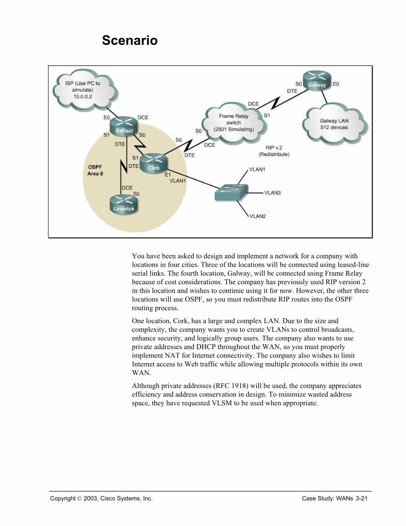
Scenario
You have been asked to design and implement a network for a company with locations in four cities. Three of the locations will be connected using leased-line serial links. The fourth location, Galway, will be connected using Frame Relay because of cost considerations. The company has previously used RIP version 2 in this location and wishes to continue using it for now. However, the other three locations will use OSPF, so you must redistribute RIP routes into the OSPF routing process.
One location, Cork, has a large and complex LAN. Due to the size and complexity, the company wants you to create VLANs to control broadcasts, enhance security, and logically group users. The company also wants to use private addresses and DHCP throughout the WAN, so you must properly implement NAT for Internet connectivity. The company also wishes to limit Internet access to Web traffic while allowing multiple protocols within its own WAN.
Although private addresses (RFC 1918) will be used, the company appreciates efficiency and address conservation in design. To minimize wasted address space, they have requested VLSM to be used when appropriate.
Copyright 2003, Cisco Systems, Inc. Case Study: WANs 3-21
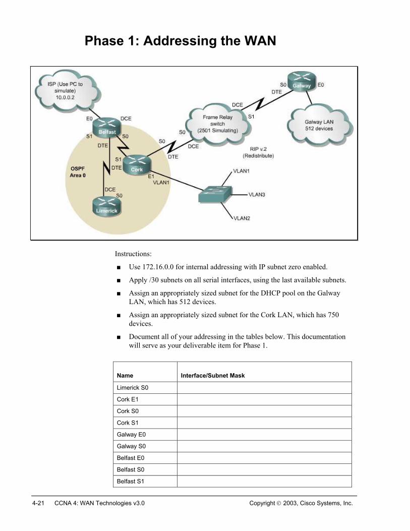
Phase 1: Addressing the WAN
Instructions:
■ Use 172.16.0.0 for internal addressing with IP subnet zero enabled.
■ Apply /30 subnets on all serial interfaces, using the last available subnets.
■ Assign an appropriately sized subnet for the DHCP pool on the Galway LAN, which has 512 devices.
■ Assign an appropriately sized subnet for the Cork LAN, which has 750 devices.
■ Document all of your addressing in the tables below. This documentation will serve as your deliverable item for Phase 1.
Name Interface/Subnet Mask
Limerick S0
Cork E1
Cork S0
Cork S1
Galway E0
Galway S0
Belfast E0
Belfast S0
Belfast S1
4-21 CCNA 4: WAN Technologies v3.0 Copyright 2003, Cisco Systems, Inc.

Name Address Pools
Galway DHCP Pool
Cork LAN
Copyright 2003, Cisco Systems, Inc. Case Study: WANs 5-21
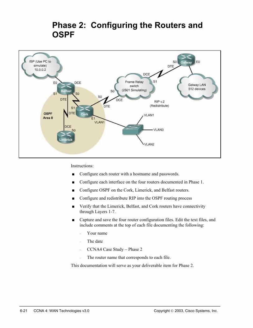
Phase 2: Configuring the Routers and OSPF
Instructions:
■ Configure each router with a hostname and passwords.
■ Configure each interface on the four routers documented in Phase 1.
■ Configure OSPF on the Cork, Limerick, and Belfast routers.
■ Configure and redistribute RIP into the OSPF routing process
■ Verify that the Limerick, Belfast, and Cork routers have connectivity through Layers 1-7.
■ Capture and save the four router configuration files. Edit the text files, and include comments at the top of each file documenting the following:
– Your name
– The date
– CCNA4 Case Study – Phase 2
– The router name that corresponds to each file.
This documentation will serve as your deliverable item for Phase 2.
6-21 CCNA 4: WAN Technologies v3.0 Copyright 2003, Cisco Systems, Inc.
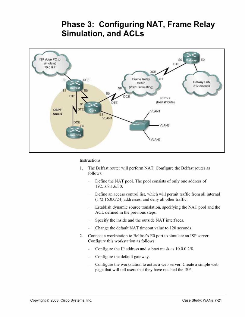
Phase 3: Configuring NAT, Frame Relay Simulation, and ACLs
Instructions:
1. The Belfast router will perform NAT. Configure the Belfast router as follows:
– Define the NAT pool. The pool consists of only one address of 192.168.1.6/30.
– Define an access control list, which will permit traffic from all internal (172.16.0.0/24) addresses, and deny all other traffic.
– Establish dynamic source translation, specifying the NAT pool and the ACL defined in the previous steps.
– Specify the inside and the outside NAT interfaces.
– Change the default NAT timeout value to 120 seconds.
2. Connect a workstation to Belfast’s E0 port to simulate an ISP server. Configure this workstation as follows:
– Configure the IP address and subnet mask as 10.0.0.2/8.
– Configure the default gateway.
– Configure the workstation to act as a web server. Create a simple web page that will tell users that they have reached the ISP.
Copyright 2003, Cisco Systems, Inc. Case Study: WANs 7-21

3. Configure the Frame Relay simulator as follows:
– Configure S0 on both the Cork router and the Galway router to use Frame Relay encapsulation.
– Configure the router between Cork and Galway to simulate a Frame Relay switch.
4. Configure an ACL to filter traffic from source addresses on the Galway LAN. The ACL should permit HTTP access to the ISP, deny all other access to the ISP, and permit all traffic to destinations within the WAN.
5. Recapture and save the Belfast, Cork, and Galway router configuration files. Capture and save the Frame Relay switch router configuration file. Edit the text files, and include comments at the top of each file documenting the following:
– Your name
– The date
– CCNA4 Case Study – Phase 3
– The router name that corresponds to each file.
Document your NAT configuration and your ISP Server configuration in the chart below.
This documentation will serve as your deliverable item for Phase 3.
Item Configured Values
Belfast: Name of NAT Pool
Belfast: ACL Number
ACL Number for ACL Filtering Galway LAN Traffic
Router for ACL Filtering Galway LAN Traffic
Configured Port for ACL Filtering Galway LAN Traffic
Configured Direction for ACL Filtering Galway LAN Traffic
ISP Server IP Address
ISP Server Subnet Mask
ISP Server Default Gateway
Filename of web page on ISP Server (include path)
8-21 CCNA 4: WAN Technologies v3.0 Copyright 2003, Cisco Systems, Inc.
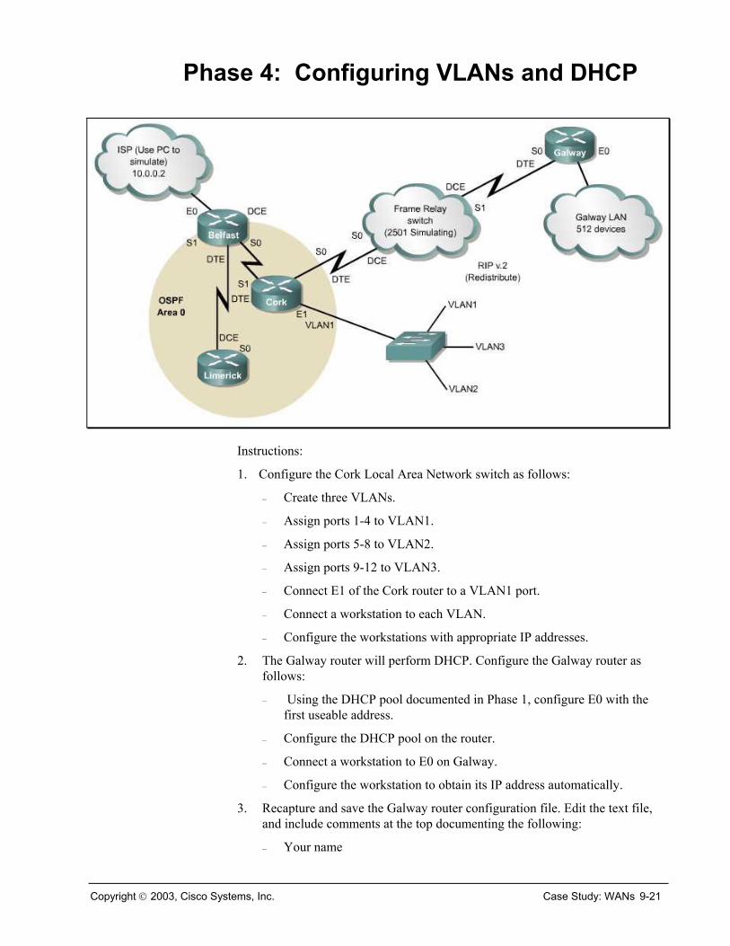
Phase 4: Configuring VLANs and DHCP
Instructions:
1. Configure the Cork Local Area Network switch as follows:
– Create three VLANs.
– Assign ports 1-4 to VLAN1.
– Assign ports 5-8 to VLAN2.
– Assign ports 9-12 to VLAN3.
– Connect E1 of the Cork router to a VLAN1 port.
– Connect a workstation to each VLAN.
– Configure the workstations with appropriate IP addresses.
2. The Galway router will perform DHCP. Configure the Galway router as follows:
– Using the DHCP pool documented in Phase 1, configure E0 with the first useable address.
– Configure the DHCP pool on the router.
– Connect a workstation to E0 on Galway.
– Configure the workstation to obtain its IP address automatically.
3. Recapture and save the Galway router configuration file. Edit the text file, and include comments at the top documenting the following:
– Your name
Copyright 2003, Cisco Systems, Inc. Case Study: WANs 9-21

– The date
– CCNA4 Case Study – Phase 4
– Galway router
This documentation will serve as your deliverable item for Phase 4.
10-21 CCNA 4: WAN Technologies v3.0 Copyright 2003, Cisco Systems, Inc.
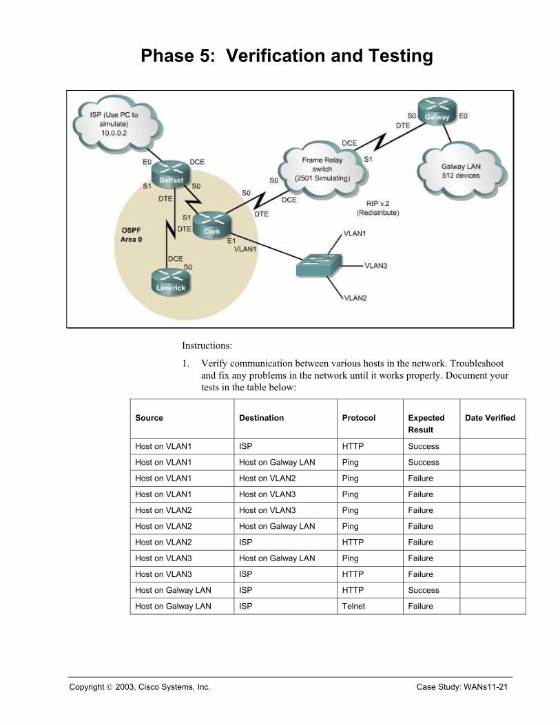
Phase 5: Verification and Testing
Instructions:
1. Verify communication between various hosts in the network. Troubleshoot and fix any problems in the network until it works properly. Document your tests in the table below:
Source Destination Protocol Expected Result
Date Verified
Host on VLAN1 ISP HTTP Success
Host on VLAN1 Host on Galway LAN Ping Success
Host on VLAN1 Host on VLAN2 Ping Failure
Host on VLAN1 Host on VLAN3 Ping Failure
Host on VLAN2 Host on VLAN3 Ping Failure
Host on VLAN2 Host on Galway LAN Ping Failure
Host on VLAN2 ISP HTTP Failure
Host on VLAN3 Host on Galway LAN Ping Failure
Host on VLAN3 ISP HTTP Failure
Host on Galway LAN ISP HTTP Success
Host on Galway LAN ISP Telnet Failure
Copyright 2003, Cisco Systems, Inc. Case Study: WANs11-21

2. Recapture and save the router configuration files for all five routers. Edit the text files, and include comments at the top of each file documenting the following:
– Your name
– The date
– CCNA4 Case Study – Final Router Configuration
– The router name that corresponds to each file.
This documentation, along with the completed tables from Phase 1, Phase 3, and Phase 5, will serve as your final deliverable item for the case study.
12-21 CCNA 4: WAN Technologies v3.0 Copyright 2003, Cisco Systems, Inc.
Instructor Notes
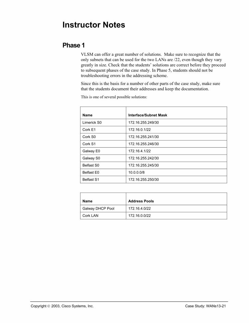
Phase 1 VLSM can offer a great number of solutions. Make sure to recognize that the only subnets that can be used for the two LANs are /22, even though they vary greatly in size. Check that the students’ solutions are correct before they proceed to subsequent phases of the case study. In Phase 5, students should not be troubleshooting errors in the addressing scheme.
Since this is the basis for a number of other parts of the case study, make sure that the students document their addresses and keep the documentation.
This is one of several possible solutions:
Name Interface/Subnet Mask
Limerick S0 172.16.255.249/30
Cork E1 172.16.0.1/22
Cork S0 172.16.255.241/30
Cork S1 172.16.255.246/30
Galway E0 172.16.4.1/22
Galway S0 172.16.255.242/30
Belfast S0 172.16.255.245/30
Belfast E0 10.0.0.0/8
Belfast S1 172.16.255.250/30
Name Address Pools
Galway DHCP Pool 172.16.4.0/22
Cork LAN 172.16.0.0/22
Copyright 2003, Cisco Systems, Inc. Case Study: WANs13-21
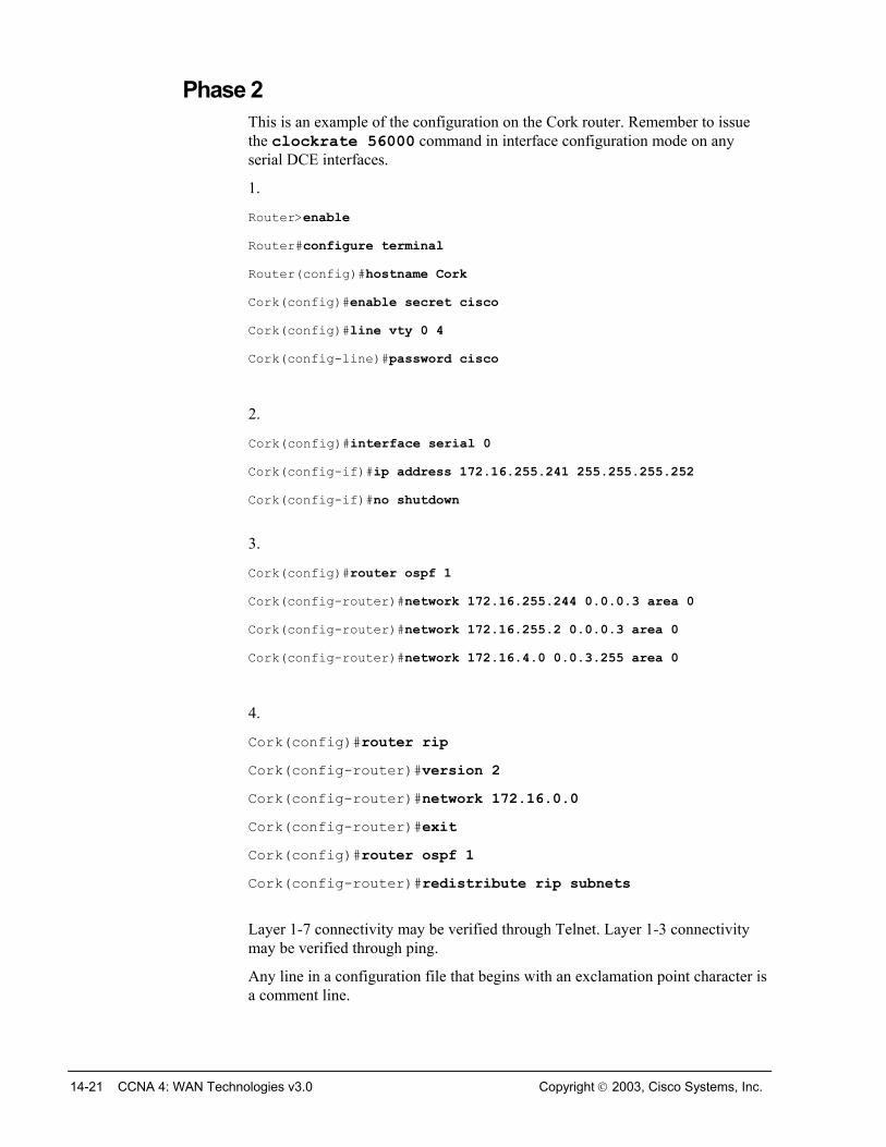
Phase 2 This is an example of the configuration on the Cork router. Remember to issue the clockrate 56000 command in interface configuration mode on any serial DCE interfaces.
1.
Router>enable Router#configure terminal Router(config)#hostname Cork Cork(config)#enable secret cisco Cork(config)#line vty 0 4 Cork(config-line)#password cisco
2.
Cork(config)#interface serial 0 Cork(config-if)#ip address 172.16.255.241 255.255.255.252 Cork(config-if)#no shutdown
3.
Cork(config)#router ospf 1 Cork(config-router)#network 172.16.255.244 0.0.0.3 area 0 Cork(config-router)#network 172.16.255.2 0.0.0.3 area 0 Cork(config-router)#network 172.16.4.0 0.0.3.255 area 0
4.
Cork(config)#router rip Cork(config-router)#version 2 Cork(config-router)#network 172.16.0.0 Cork(config-router)#exit Cork(config)#router ospf 1 Cork(config-router)#redistribute rip subnets
Layer 1-7 connectivity may be verified through Telnet. Layer 1-3 connectivity may be verified through ping.
Any line in a configuration file that begins with an exclamation point character is a comment line.
14-21 CCNA 4: WAN Technologies v3.0 Copyright 2003, Cisco Systems, Inc.
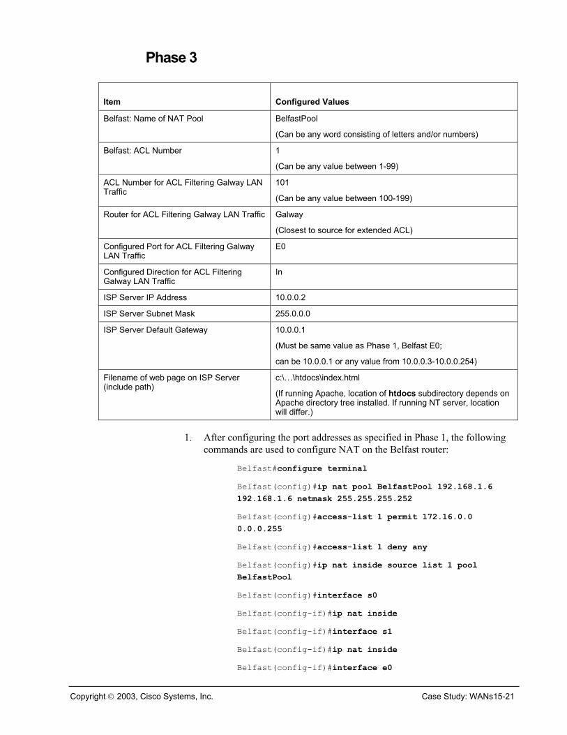
Phase 3
Item Configured Values
Belfast: Name of NAT Pool BelfastPool
(Can be any word consisting of letters and/or numbers)
Belfast: ACL Number 1
(Can be any value between 1-99)
ACL Number for ACL Filtering Galway LAN Traffic
101
(Can be any value between 100-199)
Router for ACL Filtering Galway LAN Traffic Galway
(Closest to source for extended ACL)
Configured Port for ACL Filtering Galway LAN Traffic
E0
Configured Direction for ACL Filtering Galway LAN Traffic
In
ISP Server IP Address 10.0.0.2
ISP Server Subnet Mask 255.0.0.0
ISP Server Default Gateway 10.0.0.1
(Must be same value as Phase 1, Belfast E0;
can be 10.0.0.1 or any value from 10.0.0.3-10.0.0.254)
Filename of web page on ISP Server (include path)
c:\…\htdocs\index.html
(If running Apache, location of htdocs subdirectory depends on Apache directory tree installed. If running NT server, location will differ.)
1. After configuring the port addresses as specified in Phase 1, the following
commands are used to configure NAT on the Belfast router:
Belfast#configure terminal Belfast(config)#ip nat pool BelfastPool 192.168.1.6 192.168.1.6 netmask 255.255.255.252 Belfast(config)#access-list 1 permit 172.16.0.0 0.0.0.255 Belfast(config)#access-list 1 deny any Belfast(config)#ip nat inside source list 1 pool BelfastPool Belfast(config)#interface s0 Belfast(config-if)#ip nat inside Belfast(config-if)#interface s1 Belfast(config-if)#ip nat inside Belfast(config-if)#interface e0
Copyright 2003, Cisco Systems, Inc. Case Study: WANs15-21

Belfast(config-if)#ip nat outside Belfast(config-if)#exit Belfast(config)#ip nat translation timeout 120
2. The following commands are used to configure the ISP Server workstation
(assuming that it is a Windows PC):
– Go to Control Panel, and double-click on Network.
– Double-click on TCP/IP.
– Under the IP Address tab, select Specify an IP Address. Enter 10.0.0.2 as the IP address and 255.0.0.0 as the subnet mask.
– Under the Gateway tab, enter the same IP address as configured on the E0 port of Belfast, and click Add.
– Click OK twice, and reboot the PC.
– If the ISP PC is running Windows NT, then it can be configured as an NT web server. Consult the operating system documentation for instructions.
– Alternatively, web server software (such as Apache) can be downloaded and installed.
■ This link explains how to install Apache: http://perl.about.com/library/weekly/aa020502a.htm
■ This link may be helpful in debugging the Apache installation: http://www.thesitewizard.com/archive/apache.shtml
■ Copy the HTML document that tells users that they have reached the ISP to the htdocs subdirectory in the Apache directory tree.
■ If the name of the HTML document is not index.html, search for a file named httpd.conf, and open it in a text editor. Find the line in the file that begins with DirectoryIndex, and add the filename between the word DirectoryIndex and the word index.html. The files listed after DirectoryIndex represent the prioritized order in which files will be searched for and opened.
3. The following commands are used to configure the Cork router for Phase 3:
Cork#configure terminal Cork(config)#interface s0 Cork(config-if)#encapsulation frame-relay
The following commands are used to configure the Galway router for Phase 3. The ACL shown is one of several possible solutions.
Galway#configure terminal Galway(config)#interface s0 Galway(config-if)#encapsulation frame-relay
16-21 CCNA 4: WAN Technologies v3.0 Copyright 2003, Cisco Systems, Inc.

Galway(config-if)#exit Galway(config)#access-list 101 permit any 10.0.0.2 0.0.0.0 eq 80 Galway(config)#access-list 101 deny any 10.0.0.2 0.0.0.0 Galway(config)#access-list 101 permit any any Galway(config)#interface e0 Galway(config-if)#ip access-group 101 in
The following commands are used to configure the router simulating the Frame Relay switch:
FR#configure terminal FR(config)#frame-relay switching FR(config)#interface s0 FR(config-if)#no ip address FR(config-if)#encapsulation frame-relay FR(config-if)#clock rate 56000 FR(config-if)#frame-relay intf-type dce FR(config-if)#frame-relay route 21 interface serial 1 20 FR(config-if)#no shutdown FR(config-if)#interface s1 FR(config-if)#no ip address FR(config-if)#encapsulation frame-relay FR(config-if)#clock rate 56000 FR(config-if)#frame-relay intf-type dce FR(config-if)#frame-relay route 20 interface serial 0 21 FR(config-if)#no shutdown
Copyright 2003, Cisco Systems, Inc. Case Study: WANs17-21
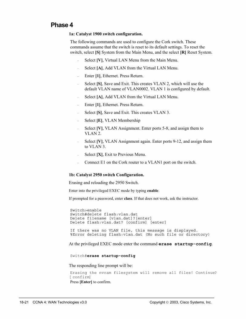
Phase 4 1a: Catalyst 1900 switch configuration.
The following commands are used to configure the Cork switch. These commands assume that the switch is reset to its default settings. To reset the switch, select [S] System from the Main Menu, and the select [R] Reset System.
– Select [V], Virtual LAN Menu from the Main Menu.
– Select [A], Add VLAN from the Virtual LAN Menu.
– Enter [1], Ethernet. Press Return.
– Select [S], Save and Exit. This creates VLAN 2, which will use the default VLAN name of VLAN0002. VLAN 1 is configured by default.
– Select [A], Add VLAN from the Virtual LAN Menu.
– Enter [1], Ethernet. Press Return.
– Select [S], Save and Exit. This creates VLAN 3.
– Select [E], VLAN Membership
– Select [V], VLAN Assignment. Enter ports 5-8, and assign them to VLAN 2.
– Select [V], VLAN Assignment again. Enter ports 9-12, and assign them to VLAN 3.
– Select [X], Exit to Previous Menu.
– Connect E1 on the Cork router to a VLAN1 port on the switch.
1b: Catalyst 2950 switch Configuration.
Erasing and reloading the 2950 Switch.
Enter into the privileged EXEC mode by typing enable.
If prompted for a password, enter class. If that does not work, ask the instructor.
Switch>enable Switch#delete flash:vlan.dat Delete filename [vlan.dat]?[enter] Delete flash:vlan.dat? [confirm] [enter] If there was no VLAN file, this message is displayed. %Error deleting flash:vlan.dat (No such file or directory)
At the privileged EXEC mode enter the command erase startup-config.
Switch#erase startup-config
The responding line prompt will be: Erasing the nvram filesystem will remove all files! Continue? [confirm] Press [Enter] to confirm.
18-21 CCNA 4: WAN Technologies v3.0 Copyright 2003, Cisco Systems, Inc.
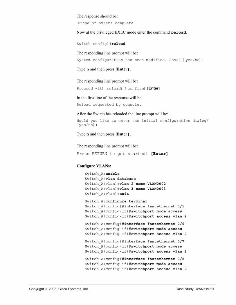
The response should be: Erase of nvram: complete
Now at the privileged EXEC mode enter the command reload.
Switch(config)#reload
The responding line prompt will be: System configuration has been modified. Save? [yes/no]: Type n and then press [Enter].
The responding line prompt will be:
Proceed with reload? [confirm] [Enter]
In the first line of the response will be: Reload requested by console.
After the Switch has reloaded the line prompt will be: Would you like to enter the initial configuration dialog? [yes/no]:
Type n and then press [Enter].
The responding line prompt will be:
Press RETURN to get started! [Enter]
Configure VLANs:
Switch_A>enable Switch_A#vlan database Switch_A(vlan)#vlan 2 name VLAN0002 Switch_A(vlan)#vlan 3 name VLAN0003 Switch_A(vlan)#exit
Switch_A#configure terminal Switch_A(config)#interface fastethernet 0/5 Switch_A(config-if)#switchport mode access Switch_A(config-if)#switchport access vlan 2
Switch_A(config)#interface fastethernet 0/6 Switch_A(config-if)#switchport mode access Switch_A(config-if)#switchport access vlan 2
Switch_A(config)#interface fastethernet 0/7 Switch_A(config-if)#switchport mode access Switch_A(config-if)#switchport access vlan 2
Switch_A(config)#interface fastethernet 0/8 Switch_A(config-if)#switchport mode access Switch_A(config-if)#switchport access vlan 2
Copyright 2003, Cisco Systems, Inc. Case Study: WANs19-21
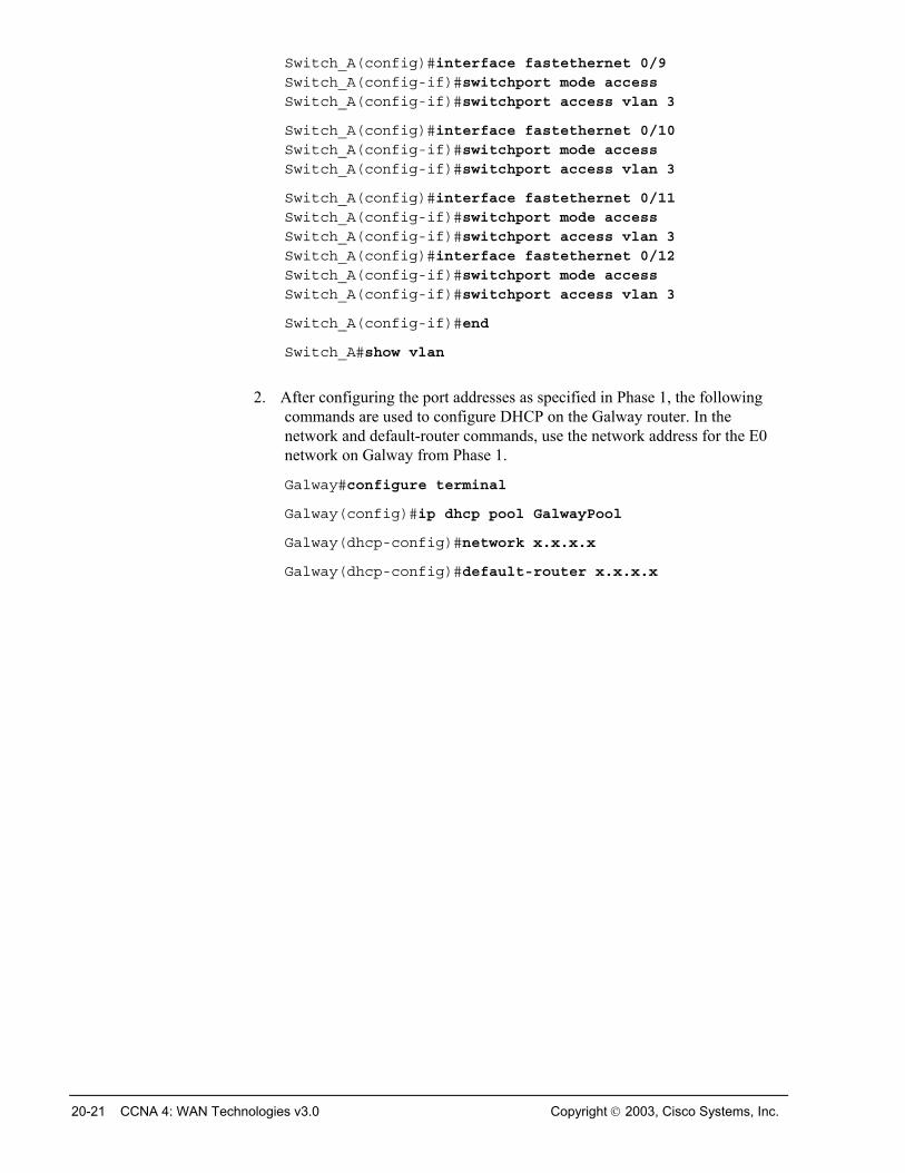
Switch_A(config)#interface fastethernet 0/9 Switch_A(config-if)#switchport mode access Switch_A(config-if)#switchport access vlan 3
Switch_A(config)#interface fastethernet 0/10 Switch_A(config-if)#switchport mode access Switch_A(config-if)#switchport access vlan 3
Switch_A(config)#interface fastethernet 0/11 Switch_A(config-if)#switchport mode access Switch_A(config-if)#switchport access vlan 3 Switch_A(config)#interface fastethernet 0/12 Switch_A(config-if)#switchport mode access Switch_A(config-if)#switchport access vlan 3
Switch_A(config-if)#end
Switch_A#show vlan
2. After configuring the port addresses as specified in Phase 1, the following
commands are used to configure DHCP on the Galway router. In the network and default-router commands, use the network address for the E0 network on Galway from Phase 1.
Galway#configure terminal
Galway(config)#ip dhcp pool GalwayPool
Galway(dhcp-config)#network x.x.x.x
Galway(dhcp-config)#default-router x.x.x.x
20-21 CCNA 4: WAN Technologies v3.0 Copyright 2003, Cisco Systems, Inc.
Phase 5 Troubleshooting is a difficult process to learn. Encourage students to be systematic about their troubleshooting techniques. If communication that is expected to succeed instead fails, students should then ping in a systematic manner beginning with the link closest to the source. The student should then proceed to the next link only upon success. There may be more than one problem preventing communication between the source and the destination. After a problem is found and fixed, the testing process should continue until communication between the source and the destination is verified.
To ensure that the hosts are configured properly, use winipcfg or ipconfig /all.
The following router commands are helpful in troubleshooting router configuration problems:
■ show running-config ■ show protocol ■ show interface ■ show ip route ■ show frame-relay
Copyright 2003, Cisco Systems, Inc. Case Study: WANs21-21