Wang, J. J. H., "Antennas for Global Navigation Satellite System ...
7
INVITED PAPER Antennas for Global Navigation Satellite System (GNSS) Global Navigation Satellite System receive antenna technologies are reviewed in this paper, and the design challenges of this exciting area of antenna design are discussed. By Johnson J. H. Wang, Life Fellow IEEE ABSTRACT | Global Navigation Satellite System (GNSS) will in effect be fully deployed and operational in a few years, even with the delays in Galileo as a consequence of European Union’s financial difficulties. The vastly broadened GNSS spectra, spread densely across 1146–1616 MHz, versus the narrow Global Positioning System (GPS) L1 and L2 bands, together with a constellation of over 100 Medium Earth Orbit (MEO) and Geostationary Earth Orbit (GEO) satellites versus GPS’ 24 MEO satellites, are revolutionizing the design of GNSS receive antennas. For example, a higher elevation cutoff angle will be preferred. As a result, fundamental changes in antenna design, new features and applications, as well as cost structures are ongoing. Existing GNSS receive antenna technologies are reviewed and design challenges are discussed. KEYWORDS | Broadband antenna; Compass; Galileo; GLONASS; GPS antenna; satellite navigation system antenna I. INTRODUCTION VFROM GPS TO GNSS Since the deployment of the Global Positioning System (GPS) by the United States and a similar GLONASS system by the Soviet Union around 1990 [1]–[3], GPS applications have proliferated globally, not only in the military arena but also in commercial and consumer markets. While the im- portance of GPS antenna relative to GPS receiver is obvious and remains, the performance and cost issues have funda- mentally changed. For example, due to drastic price reduc- tion of GPS low noise amplifier (LNA), from $800 in early 1990 to under $1 per unit today for a medium-quality single-band LNA, GPS antennas today routinely include LNA. The price of a GPS antenna also varies widely, ranging from $4 to $8000, sometimes higher than that of the receiver. Application of GLONASS has been minuscule after dissolution of the Soviet Union. Recent recovery of the Russian economy propelled by the oil boom has enabled the revitalization of GLONASS, which restarted full- constellation operation in April 2011. In 2002, the European Union started to develop Galileo. Originally targeted to start operation in 2008, Galileo suffered from years of delays due to financial and technical troubles. In 2011, its delayed plan was to have full global coverage in 2019. China began to develop Compass (Beidou) in the late 1990s, but has been fast moving in recent years, and is positioned to have a full- fledged GNSS within a few years [4]. Additionally, GPS, GLONASS, and Compass are also being augmented by Geostationary Earth Orbit (GEO) satellites to complement their Medium Earth Orbit (MEO) satellites. Several other countries have also started their regional satellite navigation systems, such as Japan’s Quasi- Zenith Satellite System (QZSS). All these satellite-based systems constitute the Global Navigation Satellite System (GNSS), with GPS, GLONASS, Galileo, and Compass being the four cornerstones with global coverage. The upcoming availability of so many satellites, and over such a wide frequency range, in GNSS constellations, as well as the move toward more unified code-division multiple-access (CDMA) approach, in the near future will offer superior performance and lower life-cycle cost, as well as new features and capabilities. These game-changing events are also enabled by newly available low-cost software-defined radio (SDR) technologies and the unpre- cedented global economy. To meet the anticipated market needs, GNSS receivers covering two or more GNSS systems have been developed and deployed at fairly low costs. While GNSS antennas will be pivotal in enabling su- perior performance, lower life-cycle cost, and new features Manuscript received July 31, 2011; revised November 21, 2011; accepted December 7, 2011. Date of publication January 13, 2012; date of current version June 14, 2012. The author is with Wang Electro-Opto Corporation (WEO), Marietta, GA 30067 USA (e-mail: [email protected]). Digital Object Identifier: 10.1109/JPROC.2011.2179630 Vol. 100, No. 7, July 2012 | Proceedings of the IEEE 2349 0018-9219/$31.00 Ó2012 IEEE
Transcript of Wang, J. J. H., "Antennas for Global Navigation Satellite System ...

INV ITEDP A P E R
Antennas for Global NavigationSatellite System (GNSS)Global Navigation Satellite System receive antenna technologies are reviewed in
this paper, and the design challenges of this exciting area of antenna design
are discussed.
By Johnson J. H. Wang, Life Fellow IEEE
ABSTRACT | Global Navigation Satellite System (GNSS) will in
effect be fully deployed and operational in a few years, even
with the delays in Galileo as a consequence of European Union’s
financial difficulties. The vastly broadened GNSS spectra,
spread densely across 1146–1616MHz, versus the narrow Global
Positioning System (GPS) L1 and L2 bands, together with a
constellation of over 100 Medium Earth Orbit (MEO) and
Geostationary Earth Orbit (GEO) satellites versus GPS’ 24 MEO
satellites, are revolutionizing the design of GNSS receive
antennas. For example, a higher elevation cutoff angle will be
preferred. As a result, fundamental changes in antenna design,
new features and applications, as well as cost structures are
ongoing. Existing GNSS receive antenna technologies are
reviewed and design challenges are discussed.
KEYWORDS | Broadband antenna; Compass; Galileo; GLONASS;
GPS antenna; satellite navigation system antenna
I . INTRODUCTIONVFROM GPS TO GNSS
Since the deployment of the Global Positioning System
(GPS) by the United States and a similar GLONASS system
by the Soviet Union around 1990 [1]–[3], GPS applications
have proliferated globally, not only in the military arena butalso in commercial and consumer markets. While the im-
portance of GPS antenna relative to GPS receiver is obvious
and remains, the performance and cost issues have funda-
mentally changed. For example, due to drastic price reduc-
tion of GPS low noise amplifier (LNA), from $800 in early
1990 to under $1 per unit today for a medium-quality
single-band LNA, GPS antennas today routinely include LNA.
The price of a GPS antenna also varies widely, ranging from
$4 to $8000, sometimes higher than that of the receiver.Application of GLONASS has been minuscule after
dissolution of the Soviet Union. Recent recovery of the
Russian economy propelled by the oil boom has enabled
the revitalization of GLONASS, which restarted full-
constellation operation in April 2011.
In 2002, the European Union started to develop
Galileo. Originally targeted to start operation in 2008,
Galileo suffered from years of delays due to financial andtechnical troubles. In 2011, its delayed plan was to have
full global coverage in 2019. China began to develop
Compass (Beidou) in the late 1990s, but has been fast
moving in recent years, and is positioned to have a full-
fledged GNSS within a few years [4].
Additionally, GPS, GLONASS, and Compass are also
being augmented by Geostationary Earth Orbit (GEO)
satellites to complement their Medium Earth Orbit (MEO)satellites. Several other countries have also started their
regional satellite navigation systems, such as Japan’s Quasi-
Zenith Satellite System (QZSS). All these satellite-based
systems constitute the Global Navigation Satellite System
(GNSS), with GPS, GLONASS, Galileo, and Compass
being the four cornerstones with global coverage.
The upcoming availability of so many satellites, and
over such a wide frequency range, in GNSS constellations,as well as the move toward more unified code-division
multiple-access (CDMA) approach, in the near future will
offer superior performance and lower life-cycle cost, as
well as new features and capabilities. These game-changing
events are also enabled by newly available low-cost
software-defined radio (SDR) technologies and the unpre-
cedented global economy. To meet the anticipated market
needs, GNSS receivers covering two or more GNSS systemshave been developed and deployed at fairly low costs.
While GNSS antennas will be pivotal in enabling su-
perior performance, lower life-cycle cost, and new features
Manuscript received July 31, 2011; revised November 21, 2011;
accepted December 7, 2011. Date of publication January 13, 2012; date of
current version June 14, 2012.
The author is with Wang Electro-Opto Corporation (WEO), Marietta, GA 30067 USA
(e-mail: [email protected]).
Digital Object Identifier: 10.1109/JPROC.2011.2179630
Vol. 100, No. 7, July 2012 | Proceedings of the IEEE 23490018-9219/$31.00 �2012 IEEE

and capabilities of new SDR receivers, books covering thistopic are scanty, scattered, and mostly outdated (e.g., [5]–
[7]). To the author’s knowledge, a book [8] and a book
chapter [9] on GNSS antennas were scheduled for publica-
tion in 2011 and 2012. This paper provides a bird’s eye
view on GNSS receive antennas, written in the context of
the latest developments and their consequential funda-
mental changes in design principles, which are departing
conventional GPS antennas.
II . RADIO-FREQUENCY (RF) PERFORMANCEPARAMETERS OF GNSS ANTENNAS
The impact of the fundamental changes from GPS to GNSS
has been recognized and taken advantage of by receiver
manufacturers. Several GNSS receivers have recently
showed up in the marketplace; and they can easily adapt
to large future changes in GNSS waveforms since they arebased on SDR technology. These GNSS receivers readily
benefit from the fairly mature and low-cost SDR technol-
ogy, which has been under continuous multibillion dollar
development programs funded by the U.S. Government
since 1980 as the SPEAKEASY programs, which were
transitioned around 2000 to the Joint Tactical Radio
System (JTRS) programs. In the commercial world, SDR
development and application have been growing rapidlysince about 2000.
On the other hand, SDR antenna development has not
had such success as the receiver. In this context, we will
discuss RF performance parameters of GNSS receive anten-
nas, highlighting changes from those for conventional GPS.
A. Operating Frequencies and BandwidthTable 1 displays signals and constellations of the four
major GNSS systems: GPS, GLONASS, Galileo, and
Compass, with the data on maximum bandwidths largelyderived from [4] and [10] for interoperability issues. GNSS
spectra are spread densely across 1146–1616 MHz, cover-
ing a frequency bandwidth of 470 MHz or an octaval
bandwidth of 1.41 : 1, with a gap of 259 MHz (1300–
1559 MHz). Obviously, future GNSS antennas will strive
to cover more bands and constellations like SDR antennas
driven by their receivers.
Note that the maximum bandwidths shown in Table 1are the maximum instantaneous bandwidth of each of the
four major constellations. Note also that they are consid-
erably larger than those adopted in many conventional GPS
antenna and receiver designs. For example, the maximum
bandwidth of conventional GPS L1 was about 20 MHz (or
�10 MHz) and is now 30.69 MHz in the GNSS scenario.
Since the receivers will be increasingly more able to
cover the entire GNSS spectrum, and take advantage of it, itis desirable and sometimes necessary that their antennas’
operating frequencies and bandwidths be consistent with
those of the SDR receivers. Additionally, large bandwidths
are needed to mitigate detuning due to changes in anten-
na’s installation environment. In practical applications,
there is also a growing trend for GNSS antennas toward
multifunction that covers not only GNSS but also some
satellite communications such as satellite radio, Iridium, etc.
B. Gain Pattern and PolarizationFig. 1 depicts two ideal elevation gain patterns, one
before and one after 2010, to highlight the fundamental
changes. The polar patterns are in spherical and rectan-
gular coordinates, with the z-axis pointing to the zenith.
The gain pattern optimizes gain and coverage for
satellites over 0� G � G �C and mitigates problems due tomultipath from satellite platform, ionosphere, tropo-
sphere, and platform environment, as well as interferences
Table 1 Signals and Constellations of Major GNSS Systems: GPS, GLONASS, Galileo, and Compass
Wang: Antennas for Global Navigation Satellite System (GNSS)
2350 Proceedings of the IEEE | Vol. 100, No. 7, July 2012

and noises over �C G � G 180�. The sharp turn at elevation
Bcutoff angle[ �C is a major design difficulty; a real-world
GNSS antenna generally has a smooth cardioid patternwith hemispherical coverage. �C is a crucial parameter
varying between applications, but is moving higher
toward the zenith with the advent of GNSS.
Right-hand circular polarization (RHCP) is universally
required for GNSS. The quality of the pattern’s polariza-
tion is expressed in either axial ratio (AR) or the relative
magnitude of its cross polarization. Generally, AR G 3 dB
or cross polarization (LHCP) of G�10 dB is desired over� G �C for a medium-quality GNSS antenna.
A minimum antenna gain Gmin in RHCP is desired over
angles � G �C. Generally, Gmin > �10 dBic in RHCP is
needed to provide sufficient signal-to-noise ratio (SNR) for
detection. But this low gain requirement can be further
relaxed by up to 10 dB or so by using various software and
hardware techniques for applications with lower precision
requirement. At elevation angles below �C, i.e., 180� >� > �C, a vanishingly small gain is desired to mitigate ter-
restrial multipath and interference signals generally strong
near the horizon.
The ideal gain pattern and spatial coverage vary from
application to application. Before 2010, conventional GPS
generally called for 80� > �C > 70� for terrestrial applica-
tions and 100� > �C > 80� for airborne applications. After
2010, GNSS applications are expected to move toward ahigher cutoff elevation angle, probably about 70� > �C >50� for terrestrial applications and 80� > �C > 60� for
airborne applications.
The trend toward a higher cutoff elevation angle �C isdue to: 1) increasingly higher interference noises near
horizon, 2) availability of more satellites near zenith, and
3) superior performance using near-zenith coverage.
Issue 1) is epitomized by the controversial terrestrial
transmission by LightSquared near GPS L1 with 1500-W
transmitters at 1525–1559 MHz, which at a half mile
from the ground station is roughly 1 billion times higher
than GPS signals [11].Issue 2) is due to the upcoming completion of the four
major GNSS constellations, with more than 100 satellites.
Issue 3) has just been successfully demonstrated by Japan’s
QZSS, which will have three geosynchronous satellites in
orbits to augment GPS in an Asia/Pacific region. QZSS uses
only satellites at elevation angles near zenith to improve
signal reception in urban canyons and mountainous ter-
rain. With only one satellite launched in 2010, tests haveshown continuous 3-cm positioning accuracy for a car
driving at 20 km/h using a conventional GPS receiver
equipped to receive correction from the QZSS satellite.
The same GPS equipment relying only on GPS signals has
accuracy of about 10 m.
C. Multipath Mitigation andInterference Suppression
The antenna is primarily a spatial filter to elevate the
SNR of line-of-sight signals from selected satellites, by
suppressing multipath and interference signals. A GNSS
antenna with higher cutoff angle �C above horizon and
good axial ratio (or low cross polarization) would have
higher antenna gain over noise temperature to detect low
line-of-sight CDMA signal desired, as demonstrated in the
QZSS tests.To suppress multipath and interference signals below
the cutoff angle �C, choke ring, resistive loading, conduct-
ing ground plane, or metamaterials are placed at the rim of
high-performance GPS antennas. The anticipated change
in �C would affect their design methodology and usage in
GNSS antennas, as they are generally bulky, heavy, and
expensive.
D. Phase Center StabilityStability of a GNSS antenna’s phase center over fre-
quency and spatial angles is a serious problem for high-
performance GNSS antennas, especially as they strive to
cover more GNSS bands and wider bandwidth. This is an
ultimate performance parameter as well as a limitation
posed by the GNSS antenna [12], [13], which will be
addressed later.
III . DESIGN CHALLENGESVSIZECONSTRAINTS, FEED NETWORK,AND COST
Challenges facing the design of GNSS receive antennas
stem from two major premises: the greatly enlarged
Fig. 1. Ideal antenna gain patterns for GPS antennas (1985–2010)
and GNSS antennas (after 2010).
Wang: Antennas for Global Navigation Satellite System (GNSS)
Vol. 100, No. 7, July 2012 | Proceedings of the IEEE 2351

bandwidth requirement and the constraints by the platformon which the antenna operates. Feed network and cost are
other major challenges. These are discussed as follows.
A. Platform-Imposed Size ConstraintAntenna size constraint and simultaneous broad-
banding are conflicting requirements facing fundamental
physical limitations, established in a rigorous analysis six
decades ago [14], which relates the fundamental limitation
of the gain bandwidth of an antenna to its electrical size.
Also, for a GNSS antenna, its platform (in a broad sense
including the platform’s immediate environment) dictateshow, and how well, the antenna can mitigate problems due
to multipath signals from satellite platform, ionosphere,
troposphere, and terrestrial environment, as well as
natural and man-made interferences and noises.
B. Feed NetworkThe feed network bridges between a coaxial cable and
the radiating aperture, providing excitation to generate
RHCP. Since the GNSS antenna needs to detect extremely
low GNSS signals, about 25 dB below noise level on Earth,
the use of LNA close to antenna is highly desirable. LNA
elevates the signal strength so that it would not beattenuated away before reaching the receiver, usually via a
cable 1–3 m long, which adds more noise as well.
Additionally, the LNA augments frequency filtering and
further enhances SNR. Because of the high-performance
benefit and low cost, use of LNA as part of GNSS antenna
is ubiquitous today. For high performance, a user may
select antenna and LNA separately.
With the transition from the narrowband, and mostlysingle band, GPS to the multiband broadband GNSS, feed
network design will be fundamentally changed not only by
performance considerations but also by production cost
issues. This challenge will be even more serious in the
more complex feed network of anti-interference GNSS
arrays with fixed or adaptive gain pattern.
C. CostThe cost of a GNSS antenna is a fundamental design
consideration driven by the market. A testimony is the
patch antenna, whose widespread use is not only due to its
low-profile, platform-compatible structure, and medium-
to-small size, but also for its low cost enabled by its simple
feed. However, the patch antenna’s performance and cost
advantages will be challenged by other antennas in the new
multiband/broadband GNSS scenario.
IV. CLASSIFICATION OF GNSSANTENNAS AND THEIRCHARACTERISTICS FROM USER’SPERSPECTIVEVBASED ONINSTALLATION PLATFORM
Section III demonstrated that a GNSS antenna’s platform
(in a broad sense including its environment) drives and
constrains its design. The broader the bandwidth, the
greater the difficulty is; and the smaller the platform, the
greater the difficulty becomes. Thus, most of the design
criteria and challenges are rooted in the platform.
Accordingly, it is reasonable to classify GNSS antennas
first by their intended platforms.A review of the numerous products in GPS World in the
annual survey of GNSS antenna manufacturers [15] con-
firms the need for a more readable classification. Table 2
proposes a simple top-level classification, dividing GNSS
antennas into four types based on their intended platform:
large, medium, small, and handheld platforms. Conven-
tional application-based classifications are used as second-tier
subclassifications (similar to how auto tires are classified).
V. BASIC GNSS ANTENNA APPROACHES
It is also desirable to know what basic antenna approaches
are taken for GNSS antennas. The answers can be found in
several books [5]–[9] covering GNSS antennas, as well as
in general antenna books, outside the GNSS context,
Table 2 GNSS Antennas Classified Based on Intended Platform, With Their General Characteristics and Anticipated Changes
Wang: Antennas for Global Navigation Satellite System (GNSS)
2352 Proceedings of the IEEE | Vol. 100, No. 7, July 2012
under the category of antennas of circular polarization
with a broad symmetrical unidirectional beam and a peak
directivity of 3–10 dBi. (A higher directivity leads to a
narrower beam, and thus a higher cutoff angle �C abovehorizon.)
This author also contacted, by both e-mail and letter,
eight of the 35 manufacturers of GNSS antennas listed in
the annual survey of GPS World [15] that had products
covering all, or almost all, GNSS bands, asking for in-
formation on design principles and technical details of
these products for possible coverage in this paper. The
responses were not enthusiastic and had little detailedinformation. This lack of adequate response was likely due
to concerns on intellectual property rights, in particular
patent rights.
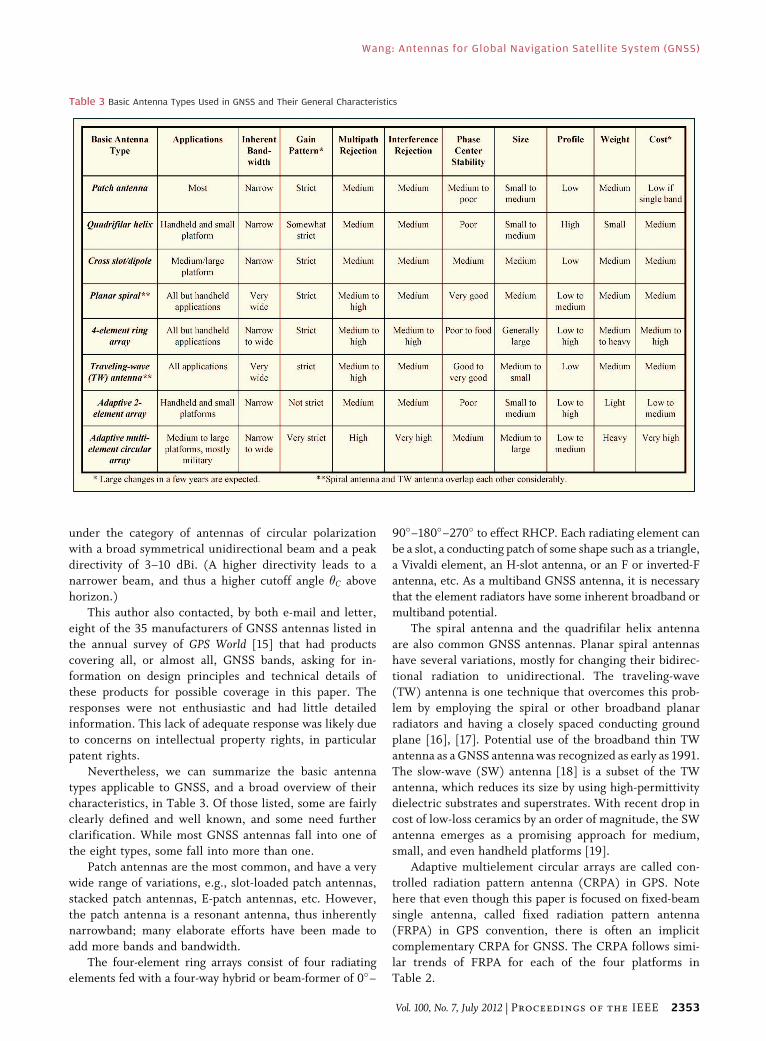
Nevertheless, we can summarize the basic antenna
types applicable to GNSS, and a broad overview of their
characteristics, in Table 3. Of those listed, some are fairly
clearly defined and well known, and some need further
clarification. While most GNSS antennas fall into one ofthe eight types, some fall into more than one.
Patch antennas are the most common, and have a very
wide range of variations, e.g., slot-loaded patch antennas,
stacked patch antennas, E-patch antennas, etc. However,
the patch antenna is a resonant antenna, thus inherently
narrowband; many elaborate efforts have been made to
add more bands and bandwidth.
The four-element ring arrays consist of four radiatingelements fed with a four-way hybrid or beam-former of 0�–
90�–180�–270� to effect RHCP. Each radiating element can
be a slot, a conducting patch of some shape such as a triangle,
a Vivaldi element, an H-slot antenna, or an F or inverted-F
antenna, etc. As a multiband GNSS antenna, it is necessarythat the element radiators have some inherent broadband or
multiband potential.
The spiral antenna and the quadrifilar helix antenna
are also common GNSS antennas. Planar spiral antennas
have several variations, mostly for changing their bidirec-
tional radiation to unidirectional. The traveling-wave
(TW) antenna is one technique that overcomes this prob-
lem by employing the spiral or other broadband planarradiators and having a closely spaced conducting ground
plane [16], [17]. Potential use of the broadband thin TW
antenna as a GNSS antenna was recognized as early as 1991.
The slow-wave (SW) antenna [18] is a subset of the TW
antenna, which reduces its size by using high-permittivity
dielectric substrates and superstrates. With recent drop in
cost of low-loss ceramics by an order of magnitude, the SW
antenna emerges as a promising approach for medium,small, and even handheld platforms [19].
Adaptive multielement circular arrays are called con-
trolled radiation pattern antenna (CRPA) in GPS. Note
here that even though this paper is focused on fixed-beam
single antenna, called fixed radiation pattern antenna
(FRPA) in GPS convention, there is often an implicit
complementary CRPA for GNSS. The CRPA follows simi-
lar trends of FRPA for each of the four platforms inTable 2.
Table 3 Basic Antenna Types Used in GNSS and Their General Characteristics
Wang: Antennas for Global Navigation Satellite System (GNSS)
Vol. 100, No. 7, July 2012 | Proceedings of the IEEE 2353

VI. HIGH-PERFORMANCE GNSSANTENNAS
High-performance GNSS antennas will clearly be the first
to respond to changes in the marketplace. Their growth
path will reflect the state of the art and cost structure of
relevant GNSS antenna technologies, monitored by gov-
ernment agencies, with data available on their websites.
The use of choke rings and other software and hardware
techniques in geodetic GNSS antennas tends to mask the
inherent merits and shortcomings of the basic antennas.Here we attempt to present a simpler overview from a pure
antenna perspective.
Two key performance issues in long-term evolution of
GNSS antennas, as discussed, are their potential to adapt to
the requirements of broadened bandwidth and elevated
cutoff angle �C. We will focus on these two characteristics by
comparing the measured data on four high-performance
GNSS antennas [12] and those on one of the Wang Electro-Opto Corporation (WEO, Marietta, GA) latest four-arm
spiral TW antenna measured in WEO’s anechoic chamber.
Fig. 2 shows comparison of their phase, thus phase
center, variation over elevation angle �. The red, blue, and
green colors designate carrier frequencies L1, L2, and L5,respectively. The data show that WEO’s spiral TW antenna
has smaller phase variations, consistent with the observa-
tion by Granger et al. [13] on spiral antennas. The WEO
GNSS antenna’s four-arm spiral, fed with an innovative
feed network [20], is in the form of a circular pillbox,
15 cm in diameter and 3 cm thick, with an inherent con-
ducting ground plane. It does not use choke ring, dissi-
pative material, or metamaterial.Fig. 3 shows measured relative polar gain patterns for
these five GNSS antennas. Note their different rates of gain
drop near the horizon, leading to 10-dB beam widths
differing by 10�–20�. The differences translate to a dif-
ference of 5�–10� in their ability to accommodate a higher �C
above the horizon desired in GNSS. Thus, the narrow-
beamed WEO antenna is more able to achieve a desired
higher cutoff angle �C above the horizon than the other four.While the measurements at WEO and those in [13] were
limited by their test chamber facilities, which apparently
were not as accurate as the anechoic test chamber of the
Goddard Space Flight Center utilized in [12], their results
are similar and in favor of the spiral antenna approach.
The findings are also consistent with theory. From the
viewpoint of geometry, phase center variation with fre-
quency and spatial angle in azimuth vanishes with increasinguniformity of the radiating structure versus angular coordi-
nate ’ and improved feed network accuracy. Similarly, and
by invoking the image theory, phase center variation in
elevation vanishes with decreasing thickness of radiating
structure and accuracy of feed network. The higher cutoff
angle of the spiral TW antenna stems from its equivalence to
an array of concentric annular slots with phased excitation.
VII. CONCLUSION ANDFUTURE RESEARCH
Vastly broadened spectra and constellations of over
100 MEO and GEO satellites in GNSS are game-changingevents that are reshaping antenna requirements toward
much broader bandwidth and higher cutoff elevation
angle. They pose new challenges not faced by conventional
GPS and give rise to new features and applications as well
Fig. 2. Comparison of measured phase variation of five
high-performance GNSS antennas.
Fig. 3. Relative gain pattern for five high-performance GNSS antennas showing different amenability to higher cutoff angle �C .
Wang: Antennas for Global Navigation Satellite System (GNSS)
2354 Proceedings of the IEEE | Vol. 100, No. 7, July 2012

as cost structures. Several high-performance GNSSantennas are evaluated to highlight the state of the art,
with the four-arm spiral TW antenna showing the highest
potential.
Future research will be redirected by these changes.
For size reduction, the slow-wave technology appears to be
a practical solution for applications from handheld to
medium platform, but needs considerable research. Forpattern control, in particular higher cutoff angle above
horizon, use of metamaterial will be pursued by some,
especially for medium and large platforms. Smart antenna
techniques will be developed to enhance performance in
small and handheld platforms in the increasingly noisier
terrestrial environment. h
RE FERENCES
[1] B. W. Parkinson and J. J. Spilker, GlobalPositioning System: Theory and Applications,vol. 1. Washington, DC: AIAA, 1996.
[2] E. D. Kaplan, Ed., Understanding GPSPrinciples and Applications. Boston, MA:Artech House, 1996.
[3] P. Misra and P. Enge, Global Position System:Signals, Measurements, and Performance,2nd ed. Lincoln, MA: Ganga-Jamuna, 2006.
[4] W. Liu, X. Zhan, L. Liu, and M. Niu, BGNSSRF compatibility assessmentVInterferenceamong GPS, galileo, and compass,[ GPSWorld, Dec. 2010. [Online]. Available:http://www.gpsworld.com/gnss-system/signal-processing/gnss-rf-compatibility-assessment-10837.
[5] J. L. Volakis, Ed., Antenna EngineeringHandbook, 4th ed. New York: McGraw-Hill,Jun. 2007.
[6] J. D. Kraus and R. J. Marhefka, Eds.,Antennas for All Applications, 3rd ed.New York: McGraw-Hill, 2002.
[7] C. A. Balanis, Ed., Modern AntennaHandbook. New York: Wiley, 2008.
[8] B. R. Rao, W. Kunysz, and K. McDonald, Eds.,GNSS Antennas. Norwood, MA: ArtechHouse, 2011.
[9] C.-C. Chen, S. Gao, and M. Maqsood,BAntennas for Global Navigation Satellite
Systems Receivers,[ in Space AntennaHandbook, W. Imbriale, S. Gao, andL. Boccia, Eds. New York: Wiley, 2012.
[10] T. A. Stansell, K. W. Hudnut, andR. G. Keegan, BFuture wave L1C signalperformance and receiver design,[ GPSWorld, Apr. 2011. [Online]. Available:http://www.gpsworld.com/gnss-system/gps-modernization/future-wave-11401.
[11] Inside GNSS, GPS Community ConfrontsLightSquared Move Into L1 Spectrum,Apr. 2011. [Online]. Available:http://www.insidegnss.com/node/2508.
[12] B. R. Schupler and T. A. Clark,BCharacterizing the behavior of geodetic GPSantennas,[ GPS World, pp. 48–55, Feb. 2001.
[13] R. Granger, P. Readman, and S. Simpson,BReady to receive: Developing a professionalantenna for GALIleo,[ GPS World, Feb. 2007.[Online]. Available: http://www.gpsworld.com/gnss-system/galileo/ready-receive-developing-a-professional-antenna-galileo-4104.
[14] L. J. Chu, BPhysical limitations ofomnidirectional antennas,[ J. Appl. Phys.,vol. 19, 1948, DOI: 10.1063/1.1715038.
[15] ‘‘2011 antenna survey,’’ GPS World, p. 4.[Online]. Available: http://www.gpsworld.com/antennasurvey
[16] J. J. H. Wang, BThe spiral as a travelingwave structure for broadband antennaapplications,[ Electromagnetics, vol. 20,pp. 323–342, Jul.–Aug. 2000.
[17] J. J. H. Wang and D. J. Triplett,BHigh-performance universal GNSS antennaand enhancement techniques to overcome itsperformance limitations,[ in Proc. IEEE Int.Symp. Antennas Propag., Toronto, ON, Canada,Jul. 11–17, 2010, DOI: 10.1109/APS.2010.5560970.
[18] J. J. H. Wang and J. K. Tillery, BBroadbandminiaturized slow-wave antenna,[ U.S. Patent6 137 453, Oct. 24, 2000.
[19] J. J. H. Wang, D. J. Triplett, andS. C. Workman, BMiniaturized planarslow-wave antennas and their application toultrawideband multifunction antennas,[ inProc. IEEE Int. Symp. Microw. Antenna Propag.EMC Technol., Beijing, China, Nov. 1–3, 2011,pp. 733–736.
[20] J. J. H. Wang, BUltra-wideband conformallow-profile four-arm unidirectionaltraveling-wave (TW) antennas with a simplefeed,[ U.S. Patent 61/469409 (pending),Mar. 30, 2011.
ABOUT T HE AUTHO R
Johnson J. H. Wang (Life Fellow, IEEE) received
the B.S.E.E. degree from National Taiwan Univer-
sity, Taipei, Taiwan, in 1962 and the Ph.D. degree
in electrical engineering from the Ohio State
University, Columbus, in 1968.
Since 1991, he has been Chief Scientist and
President of Wang Electro-Opto Corporation
(WEO), Marietta, GA. From 1975 to January 1995,
he was on the faculty of the Georgia Institute of
Technology (Georgia Tech), Atlanta. Prior to
coming to Georgia Tech in 1975, he had seven years of industrial
experience in the design of various antennas and phased arrays. At
Georgia Tech, his research was in the area of antennas, microwaves, and
electromagnetic theory. A focus of his research was the computation of a
variety of 3-D electromagnetic problems using digital computers by the
method of moments. His current fields of interest are broadband/
multiband low-profile conformable antennas, smart antennas, software-
defined arrays, ultrawideband phased array antenna systems, multifunc-
tion and diversity antenna systems employing modern microwave and
lightwave technologies, digital beam forming, as well as wireless
telecommunications. He is the author of a widely used textbook on
advanced electromagnetics and computer numerical analysis, General-
ized Moment Methods in ElectromagneticsVFormulation and Computer
Solution of Integral Equations (New York, NY: Wiley, 1991).
Dr. Wang is active in the IEEE Antennas and Propagation Society, the
IEEE Microwave Theory and Techniques (MTT) Society, and the IEEE
Communications Society. He is a Fellow of The Electromagnetics
Academy.
Wang: Antennas for Global Navigation Satellite System (GNSS)
Vol. 100, No. 7, July 2012 | Proceedings of the IEEE 2355