WAM MU Vibrating Bin Bottoms Tech Manual JECcatalog.jamiesonequipment.com/Asset/WAM MU Vibrating Bin...
68
TECHNICAL CATALOGUE /,9( %,1 %277206 TECHNICAL CATALOGUE SCHNECKENAUSTRAGEBÖDEN TECHNISCHER KATALOG (;75$&7(856 08/7,3/(6 ¬ 9,6 CATALOGUE TECHNIQUE ESTRATTORI MULTIPLI A COCLEA CATALOGO TECNICO All rights reserved © WAMGROUP S.p.A. MU 1 CATALOGUE &217/ ISSUE $ LATEST UPDATE CIRCULATION
Transcript of WAM MU Vibrating Bin Bottoms Tech Manual JECcatalog.jamiesonequipment.com/Asset/WAM MU Vibrating Bin...

TEC
HN
ICA
L C
ATA
LOG
UE
TECHNICAL CATALOGUE
SCHNECKENAUSTRAGEBÖDENTECHNISCHER KATALOG
CATALOGUE TECHNIQUE
ESTRATTORI MULTIPLI A COCLEACATALOGO TECNICO
All
right
s re
serv
ed ©
WA
MG
RO
UP
S.p
.A.
MU
1
CATALOGUE
ISSUE LATEST UPDATECIRCULATION

All the products described in this catalogue are manufactured according to WAMGROUP S.p.A. Quality System procedures.UNI EN ISO 9002 and extended to
the latest release of UNI EN ISO 9001, ensures that the entire production process, starting from the processing of the order to the technical service after delivery, is carried out in a controlled manner that guarantees the quality standard of the product.
Alle in diesem Katalog beschriebenen Produkte werden gemäß dem Qualitätssystem der WAMGROUP S.p.A. hergestellt.Das im Juli 1994 gemäß der internationalen Norm UNI EN ISO 9002 und auf die neueste Version der UNI EN ISO 9001 erweiter-
gewährleistet ist.
Tous les produits décrits dans ce catalogue sont fabriqués selon les procédures du Système de Qualité de WAMGROUP S.p.A., UNI EN ISO 9002 et étendu à la dernière version de la norme UNI EN ISO
9001. Cela garantit que le processus de production, à partir de la gestion de la commande au service technique après-vente, est effectué de manière contrôlée garantissant la norme de qualité du produit.
procedure del Sistema Qualità di WAMGROUP S.p.A. UNI EN ISO 9002 -
UNI EN ISO 9001
This publication cancels and replaces any previous edition and revision.
Diese Veröffentlichung storniert und ersetzt alle früheren Ausgaben und überarbeiteten Fassungen.Wir behalten uns das Recht vor, Änderungen ohne vorherige Information durchzuführen.
Dieser Katalog darf ohne vorherige Genehmigung weder ganz noch teilweise vervielfältigt werden.
Cette publication annule et remplace toute édition et révision antérieure.
Ce catalogue ne peut être reproduit, même partiellement, sans notre consentement préalable.
Questa pubblicazione annulla e sostituisce le edizioni e revisioni precedenti. Ci riserviamo la facoltà di apportare modi che senza preavviso.
Il presente catalogo non può essere riprodotto, nemmeno parzialmente, senza previo consenso.

CODE INDEX........................................................................................................................INTRODUCTION ..................................................................................................................STANDARD SUPPLY.............................................................................................................OVERALL DIMENSION AN-TYPE........................................................................................ACCESSORIES......................................................................................................................MU_P - MU_E STRUCTURAL COMPONENTS.................................................................MU_P - MU_E MECHANICAL COMPONENTS ................................................................DIRECT DRIVE (S-TYPE GEAR REDUCER).....................................................................DRIVE UNIT LAYOUT...........................................................................................................FINISHING..............................................................................................................................COLOURS........................................................................................................................... ..MU TYPE MODULAR CODE KEY........................................................................................INQUIRY FORM....................................................................................................................MEDIUM-HEAVY DUTY TROG............................................................................................EXTRA-HEAVY DUTY TROG................................................................................................TROUGH FLANGE DRILLING..............................................................................................END PLATE XP - TYPE ........................................................................................................END PLATE............................................................................................................................DRILLING SHEME.................................................................................................................SCREW DIRECTION AND ROTATION...............................................................................P SCREW...............................................................................................................................E SCREW...............................................................................................................................
TROUGH COVER.................................................................................................................COVER LOCK........................................................................................................................
SHAFT SEALING TYPE - XUC............................................................................................SHAFT COUPLINGS XAA and XAC.....................................................................................SHAFT COUPLING XAV........................................................................................................GEAR REDUCER - TYPE S 21-23-25-27............................................................................MOTOR MT............................................................................................................................
OPTIONS - SHAFT COUPLINGS XAQ-XAT.............................................................................OPTIONS - COUPLING TRANSMISSION (“S”-TYPE GEAR REDUCER).......................OPTIONS - CHAIN TRANSMISSION (“S”-TYPE GEAR REDUCER)...............................
ACCESSORIES - SQUARE INLET......................................................................................
ACCESSORIES - REINFORCEMENT RINGS...................................................................
TROUGH CONFIGURATION Ø 100 - 250...........................................................................SHIPPING DATA ....................................................................................................................WEIGHTS MU_P....................................................................................................................WEIGHTS MU_E AN............................................................................................................
CODES..................................................................................................................EINFÜHRUNG...........................................................................................................STANDARD-LIEFERUMFANG..................................................................................
MECHANISCHE KOMPONENTEN MU_P - MU_E...................................................
FINISH.......................................................................................................................
SUCHCODESCHLÜSSEL TYP MU...........................................................................ANFRAGEFORMULAR.............................................................................................TROG MITTELSCHWER...........................................................................................TROG SCHWER........................................................................................................
ENDSCHILD XP.........................................................................................................ENDSCHILD..............................................................................................................
SCHNECKENWENDEL P..........................................................................................SCHNECKENWENDEL E.........................................................................................
ENDLAGEREINHEIT XSP.........................................................................................ENDLAGEREINHEIT XSR........................................................................................
MOTOR MT................................................................................................................
VARIANTEN - PADDELWENDEL..............................................................................VARIANTEN - ENDLAGEREINHEIT TYP XSQ.........................................................VARIANTEN - ENDLAGEREINHEIT TYP XSS.........................................................
TROGKONFIGURATION Ø 100 - 250.......................................................................KOLLIDATEN ............................................................................................................GEWICHTE MU_P.....................................................................................................GEWICHTEMU_E AN...............................................................................................
1
1 1

CODES ET SIGLES......................................................................................................................INTRODUCTION ........................................................................................................................COMPOSITION STANDARD.......................................................................................................
ACCESSOIRES............................................................................................................................COMPOSANTS STRUCTURE MU_P - MU_E..........................................................................COMPOSANTS MECANIQUES MU_P - MU_E........................................................................ENTRAINEMENT DIRECTE (REDUCTEUR TYPE “S”)..........................................................POSITIONS DES MOTORISATIONS..........................................................................................FINITION.......................................................................................................................................TONALITES..................................................................................................................................CODE MODULAIRE TYP MU....................................................................................................FICHE DE DOMANDE................................................................................................................AUGE SERVICE LOURD.............................................................................................................AUGE EXTRA LOURD.................................................................................................................
FLASQUE COTE XP.....................................................................................................................FLASQUE.....................................................................................................................................SCHÉMA DE PERÇAGE.............................................................................................................SENS DE L’HÉLICE ET SENS DE ROTATION..........................................................................SPIRE P.........................................................................................................................................SPIRE E........................................................................................................................................
CAPOTAGE..................................................................................................................................FERMETURE CAPOTAGE.........................................................................................................SUPPORT PALIER D’EXTREMITE TYPE XSP..........................................................................SUPPORT PALIER D’EXTREMITE TYPE XSR.........................................................................ETANCHEITE TYP XUC.............................................................................................................ACCOUPLEMENTS XAA et XAC................................................................................................ACCOUPLEMENT XAV................................................................................................................REDUCTEUR TYPE S 21-23-25-27............................................................................................MOTEUR MT................................................................................................................................OPTIONS- ACCOUPLEMET CANNELE ET DEFONCE XAL..................................................OPTIONS- ACCOUPLEMETS XAQ-XAT........................................................................................OPTIONS - ENTRAINEM. AV.ACCOUPL.DEMI-ELASTIQUE (RED.TYPE “S”).....................OPTIONS - ENTRAINEMENT PAR CHAINE (REDUCTEUR TYPE “S”)...............................OPTIONS - SPIRE A PALETTES.................................................................................................OPTIONS - SUPPORT PALIER D’EXTREMITE TYPE XSQ.....................................................OPTIONS - SUPPORT PALIER D’EXTREMITE TYPE XSS......................................................
ÉTANCHÉITÉ INTERNE ADDITIONNELLE...............................................................................
ACCESSOIRES - ANNEAUX DE RENFORT.............................................................................
DISPOSITION CONSTRUCTIVE ...............................................................................................COLISAGE ...................................................................................................................................POIDS MU_P................................................................................................................................POIDS MU_E AN.........................................................................................................................
CODICI E SIGLE.............................................................................................INTRODUZIONE ...............................................................................................FORNITURA STANDARD...................................................................................
ACCESSORI......................................................................................................COMPONENTI COMPONENTI CARPENTERIA MU_P - MU_E.......................COMPONENTI MECCANICA MU_P - MU_E....................................................MOTORIZZAZIONE DIRETTA (TESTATA MOTRICE TIPO “S”)........................DISPOSIZIONE MOTORIZZAZIONI...................................................................FINITURA...........................................................................................................TONALITÀ..............................................................................................................CHIAVE SIGLA MODULARE TIPO MU..............................................................MODULO RICHIESTA........................................................................................TRUOGOLO PESANTE.....................................................................................TRUOGOLO EXTRAPESANTE.........................................................................FORATURA FLANGIA TRUOGOLO...................................................................PORTASUPPORTO XP.......................................................................................PORTASUPPORTO............................................................................................SCHEMA DI FORATURA...................................................................................SENSO DELL’ELICA E VERSO DI ROTAZIONE...............................................SPIRA P.............................................................................................................SPIRA E.............................................................................................................
COPERCHIO......................................................................................................CHIUSURA COPERCHIO..................................................................................SUPPORTO D’ESTREMITÁ XSP.......................................................................SUPPORTO D’ESTREMITÁ XSR......................................................................TENUTA XUC....................................................................................................ACCOPPIAMENTI XAA e XAC...........................................................................ACCOPPIAMENTO XAV...................................................................................TESTATA MOTRICE S 21-23-25-27...................................................................MOTORE MT......................................................................................................OPZIONI - ACCOPPIAMENTO CALETTATO SPINATO XAL.............................OPZIONI - ACCOPPIAMENTI XAQ-XAT............................................................OPZIONI - TRASMISSIONE CON GIUNTO (TEST.MOTR.TIPO “S”)................OPZIONI - TRASMISSIONE A CATENA (TEST.MOTR.TIPO “S”).....................OPZIONI - ELICA A PALETTE............................................................................OPZIONI - SUPPORTO D’ESTREMITÁ XSQ....................................................OPZIONI - SUPPORTO D’ESTREMITÁ XSS....................................................
ACCESSORI - RETE SOTTOPORTELLO XKX.................................................
ACCESSORI - ANELLI DI RINFORZO...............................................................
DISPOSIZIONE TRUOGOLI .............................................................................
PESI MU_P........................................................................................................PESI MU_E AN..................................................................................................
1
1 1

1
Estrattore multiplo pesante
Estrattore multiplo extra pesante
Testata motrice
Testata motrice
Testata motrice
Testata motrice
Truogolo
Portasupporto
Elica
Coperchio
Chiusura coperchio
Supporto d’estremità
Supporto d’estremità
Accoppiamento albero
Accoppiamento albero
Accoppiamento albero
Tenuta
Motore
Trasmissione
Portello apribile
Rete sottoportello
Portello a membrana
Sottocoperchio
Diaframma divisorio
Inserto tubolare
Sella
Morsetto a vite
XE
XF
XJV
XJE
Extracteur multiple lourd
Extracteur multiple extra lourd
Réducteur
Réducteur
Réducteur
Réducteur
Auge
Flasque
Helice
Couvercle
Fermeture capotage
Support palier d’extrémité
Support palier d’extrémité
Accouplement arbre
Accouplement arbre
Accouplement arbre
Etanchéité
Moteur électrique
Entraînement
Capot mobile
Grille sous capot
Trappe à membrane
Support capot
Diapharagme de division
Insert tubulaire
Semelle support
Pince à vis
Heavy-duty live bin bottom
Extra-heavy-duty live bin bottom
Gear reducer
Gear reducer
Gear reducer
Gear reducer
Trough
End plate
Screw
Trough cover
Cover lock
End bearing assembly
End bearing assembly
Shaft coupling
Shaft coupling
Shaft coupling
Shaft sealing
Electric motor
Transmission
Square spout
Rectangular spout
Rectangular spout
Flush outlet
Membrane hatch
Cover support bracket
Separating diaphgram
Flow stopping diaphragm
Tubular insert
Rotational indicator bracket
Trough foot
Screw clamp
Austragsschneckenboden mittelschwer
Austragsschneckenboden schwer
Getriebe
Getriebe
Getriebe
Getriebe
Trog
Endschild
Wendel
Trogabdeckung
Abdeckungsverschluß
Endlagereinheit
Endlagereinheit
Wellenverbindung
Wellenverbindung
Wellenverbindung
Wellenabdicthung
Elektromotor
Kraftübertragung
Frontalauslauf
Überlaufklappe
Membranklappe
Trennwehr
Verdrängungselement
Trogfuß
Endschalter-Grundplatte
Grundplatte und Endschalter

1
= estrattori multipli a ca-
complete di testata motrice.
= estrattori multipli a ca--
sante, complete di testata motrice.
=come supporti intermedi, con
=come supporti intermedi, con
= come maad albero nudo.
= come maad albero nudo.
= come maad albero nudo.
= come maad albero nudo.
Queste macchine sono in acciaio al carbonio e NON sono idonee al tra-sporto di prodotti alimentari.
prima che la macchina/impianto nel quale devono essere installate sia
In quest’ambito è cura dell’impiantista / installatore predisporre ed installare
di evitare danni a cose o persone in caso di rotture e conseguente caduta
del motore).Per prodotti pericolosi, nocivi al con-
esplosivi e pericolosi dal punto di vista batteriologico e/o virale, l’impiantista e/o l’installatore, dovranno prevedere idonei dispositivi all’uopo.
La geometria e la forma dell’MU sono dimensionati come sistema per l’estra-
strutturale di fondo di una tramoggia, di un silo o di qualunque altro contenitore. Sarà cura dell’installatore supportarlo correttamente.
= extracteurs multiples en auge pour service lourd, motorisation comprise.
= extracteurs multiples en auge pour service extra-lourd, motorisation comprise.
=comme mais avec longeur majorée sans paliers intermédiaires.
=comme mais avec longeur majorée sans paliers intermédiaires.
= comme mais à arbre nu.
= comme mais à arbre nu.
= comme mais à arbre nu.
= comme mais à arbre nu.
Ces machines NE sont PAS indi-quées au transport de produits alimentaires.En outre, il est interdit de les mettre en fonction avant que la machine / l’installation dans laquelle elles doivent être montées a été déclarée conforme aux dispositions de la Direc-
Dans ce cadre il est la responsabilité du constructeur de l’installation ou de l’installateur de projeter et d’installer tout équipement de protection néces-
/ ou des parties d’elle puissent causer de dégâts à des personnes et / ou
appropriées contre la chaute du moteur etc.).Pour des produits dangereux, nui-sibles au contact et/ou à l’inhalation,
du point de vue bactériologique et/ou viral, le constructeur de l’installation ou l’installateur devront prévoir des dispositifs appropriés au besoin.
La géométrie et la forme des extrac-teurs multiples à vis sont dimension-nés comme système pourl’extraction du produit. Les MU ne sont donc pas dimensionnés pour mener la fonction structurale de fond d’une trémie, ou d’un silo ou de n’importe quel autre type de récipient. Il est la responsabilité de l’installateur de supporter l’extracteur MU correcte-ment.
= Austragschnecken-boden in mittelschwerer Ausführung inkl. Antriebs-einheit.
= Austragschnecken-boden in schwerer Aus-füh-rung inkl. Antriebseinheit.
= wie , jedoch Überlänge ohne Zwischen-lager.
= wie , jedoch Überlänge ohne Zwischen-lager.
= wie jedoch mit freiem Wellenende ohne Antrieb.
= wie jedoch mit freiem Wellenende ohne Antrieb.
= wie jedoch mit freiem Welle-nende ohne Antrieb.
= wie jedoch mit freiem Welle-nende ohne Antrieb.
Die in dieser Dokumentation genann-ten Schneckenförderer sind NICHT
geeignet.
genommen werden, bevor sowohl sie selbst, als auch die Anlage, in die sie eingebaut wird, mit den Vorschriften
erklärt wurde.Es liegt in der Verantwortung des
-
durch einen Geräte- oder Teiledefekt Personen- und/oder Sachschäden
Motors etc.).
die nicht mit dem menschlichen Körper in Kontakt geraten oder eingeatmet
explosive sowie bakteriologisch ge-fährliche Medien muß der Anlagenbau-
erforderlichen Vorrichtungen vorsehen und Maßnahmen treffen.
Geometrie und Form der MU Schnek-kenaustragsböden entsprechen allein der Anforderung, ein Schüttgut aus-
-böden sind nicht dafür ausgelegt,
erfüllen. Es liegt in der Verantwortung des Anlagenaufstellers, den Trichter,
= Heavy-duty live bin bottom, complete with gear motor.
= Extra-heavy-duty live bin bottom, complete with gear motor.
=same as but beyond standard length without intermediate han-ger bearings.
=same as but beyond standard length without intermediate han-ger bearings.
= same as but with bare shaft only.
= same as but with bare shaft only.
=same asbut with bare shaft only.
= same as but with bare shaft only.
This equipment is NOT suitable for handing of foodstuff.The screw conveyor must not be starded before the screw conveyor itself, as well as the plant it is going to be installed in, have been declared in conformity with the European Directive
responsability to design and install all necessary protection in order to avoid that breaking and / or yielding of the equipment or of parts of it might dam-age people and / or parts of the plant (e.g. adequate protection against fall-ing down of the motor etc.).For dangerous materials, i.e. those that must not get in contact with the human body or be inhaled, for flammable, explosive and bacteriologically danger-ous materials the plant manufacturer
safety devices and measures.
Geometry and shape of MU Live
material discharging device. MU Live
structural support functions of a bin, hopper or silo bottom. It is the plant fitter’s responsibility to support the silo, hopper or bin in a correct fashion.

1
1 ELECTRIC MOTOR ELEKTROMOTOR MOTEUR ELECTRIQUE MOTORE ELETTRICO
TROUGH TROG AUGE TRUOGOLO
END PLATE ENDSCHILD REHAUSSE PORTA SUPPORTO
SCREW SCHNECKENWENDEL SPIRE SPIRA XE-
11
SUPPORT DE CAPOTS SOTTOCOPERCHI
111

1
G
F
D
C
A
E
H
Ø E F
WENDELN
ELICHE
WENDELN
ELICHE
WENDELN
ELICHE
WENDELN
ELICHE
WENDELN
ELICHE
1.5 - 2 - 2.5 - 3 505 670 835 1000 172 86 115 182
1.5 - 2 - 2.5 - 3 665 885 1105 1325 222 111 185 135 182
1.5 - 2 - 2.5 - 3 815 1085 1355 1625 262 131 215 160 225
1285 1605 315 157.5 233 151
755 1135 1515 2275 370 185 275 235 233 151
2.5 - 3 - 3.5 850 1275 1700 2125 2550 208.5 305 270 267 162
2.5 - 3 1565 2085 2605 3125 512 256 380 310 180
1865 3105 3725 607 303.5 310 180
Contact the Manufacturer - Beim Hersteller nachfragenConsulter le Fabricant - Consultare il Costruttore

1
1
Coupling transmission Kupplung Entraînement par accouplement Trasmissione con giunto
Chain transmission Kettentrieb Entraînement par chaîne Trasmissione a catena
11
Membrane hatch Membranklappe Trappe à membrane Portello a membrana XKY
1
11

1
Ø Trog
Truogolo
SchneckenwendelSpira
InnenrohrTubo interno
Einlauf
Carico
Auslauf
Scarico
Abdeckung
Coperchio
Befest. Abdeckung
Fissaggio coperchioSteig.
Passo
Ø
3 150 60 3
VariableVariabelVariabileVariable
60 7
on requestauf Wunschsur demandesu richiesta
XFCC
Geschraubt
Bulloni
3 200 60 60 7 XFCC
3 250 60 60 7 XFCC
300 7 XFCC
350 7 XFCC
5 7 XFCC
500 5 7 XFCC
600 168 6 168 7 XFCC
Ø Trog
Truogolo
SchneckenwendelSpira
InnenrohrTubo interno
Einlauf
Carico
Auslauf
Scarico
Abdeckung
Coperchio
Befest. Abdeckung
Fissaggio coperchioSteig.
Passo
Ø
150 60
VariableVariabelVariabileVariable
60 7
on requestauf Wunschsur demandesu richiesta
XFCC
Geschraubt
Bulloni
200 60 60 7 XFCC
250 60 5 60 7 XFCC
6 300 5 7 XFCC
6 350 5 7 XFCC
6 6 7 XFCC
6 500 6 7 XFCC
6 600 168 8 168 7 XFCC
Contact the Manufacturer - Beim Hersteller nachfragenConsulter le Fabricant - Consultare il Costruttore
Contact the Manufacturer - Beim Hersteller nachfragenConsulter le Fabricant - Consultare il Costruttore

1
Ø LEinlaufendlager bei
auslaufs. Antr.
Testata carico permotorizz. lato carico
Auslaufendlager beieinlaufs. Antriebe
Testata scarico permotorizz. lato scarico
Wellenverbindungeinlaufseitig
Accoppiamento carico
Wellenverbindungauslaufseitig
Accoppiamento scarico
Wellenabdichtung
Tenuta
3 XSP035A_1
3 XSP035A_1
3
XSP055A_1
XSP055A_1
3.5 XSP055A_1
3 XSP065A_1
XSP065A_1 XAQ075T1681 XAQ075T1681
Ø LEinlaufendlager bei
auslaufs. Antr.
Testata carico permotorizz. lato carico
Auslaufendlager beieinlaufs. Antriebe
Testata scarico permotorizz. lato scarico
Wellenverbindungeinlaufseitig
Accoppiamento carico
Wellenverbindungauslaufseitig
Accoppiamento scarico
Wellenabdichtung
Tenuta
3 XSR035A_1 XAV085T0601 XAV085T0601
3 XSR035A_1 XAV085T0601 XAV085T0601
3 XAV100T0601 XAV100T0601
XSR055A_1
XSR055A_1
3.5 XSR055A_1
3 XSR065A_1
XSR065A_1 XAT125T1681 XAT125T1681
Contact the Manufacturer - Beim Hersteller nachfragenConsulter le Fabricant - Consultare il Costruttore
Contact the Manufacturer - Beim Hersteller nachfragenConsulter le Fabricant - Consultare il Costruttore

1
FC
A
A6
Ø H
K
E

1
WENDEL - ELICHE
WENDEL - ELICHE
Outlet - AuslaufSortie - Scarico
Inlet - EinlaufEntrée - Carico
Drive unit at inlet, direct, 1 to LH.Gear transmission at outlet.
1 Direktantrieb am Einlaufendet links,Übersetzungsvorgelege am Auslauf.
Motorisation au chargement en direct 1 à g.Renvoi sur la sortie.
Motorizzazione al carico in diretta 1 a sx.Rinvio allo scarico.
1
1
Drive unit at inlet, direct, 1 central.Gear transmission at outlet.
1 Direktantrieb am Einlauf zentral,Übersetzungsvorgelege am Auslauf.
Motorisation au chargement en direct 1 central.Renvoi sur la sortie.
Motorizzazione al carico in diretta 1 centrale.Rinvio allo scarico.
Outlet - AuslaufSortie - Scarico
Inlet - EinlaufEntrée - Carico
View from inlet - Ansicht von EinlaufVue de chargement - Vista da carico
View from inlet - Ansicht von EinlaufVue de chargement - Vista da carico

1
WENDEL - ELICHE
WENDEL - ELICHE
2 drive units at inlet end, direct to LH of each group of 2.Gear transmission at outlet.
2 Direktantriebe am Einlaufende links von jeder ZweiergruppeÜbersetzungsvorgelege am Auslauf.
Motorisation 2 au chargement en direct à g. de chaque groupe de 2Renvoi sur la sortie.
Motorizzazione 2 al carico in diretta a sx di ogni gruppo da 2Rinvio allo scarico.
1
1 Drive unit with 3 motors, 2 on sides, 1 central.Int. gear at outlet on two outer units
3 Antriebe, 2 seitliche, 1 zentraler, einlaufseitig Übersetzungsvorgelege am Auslaufende an den beiden außen liegenden Wendelpaaren
Motorisation à 3 moteurs, 2 latéraux 1 centralRenvoi côté déchargement sur deux groupes extérieurs
Motorizzazione a 3 motori, 2 laterali 1 centraleRinvio lato scarico sui due gruppi esterni
Outlet - Auslauf Sortie - Scarico
Inlet - EinlaufEntrée - Carico
Outlet - AuslaufSortie - Scarico
Inlet - EinlaufEntrée - Carico
View from inlet - Ansicht von EinlaufVue de chargement - Vista da carico
View from inlet - Ansicht von EinlaufVue de chargement - Vista da carico
1
WENDEL - ELICHE
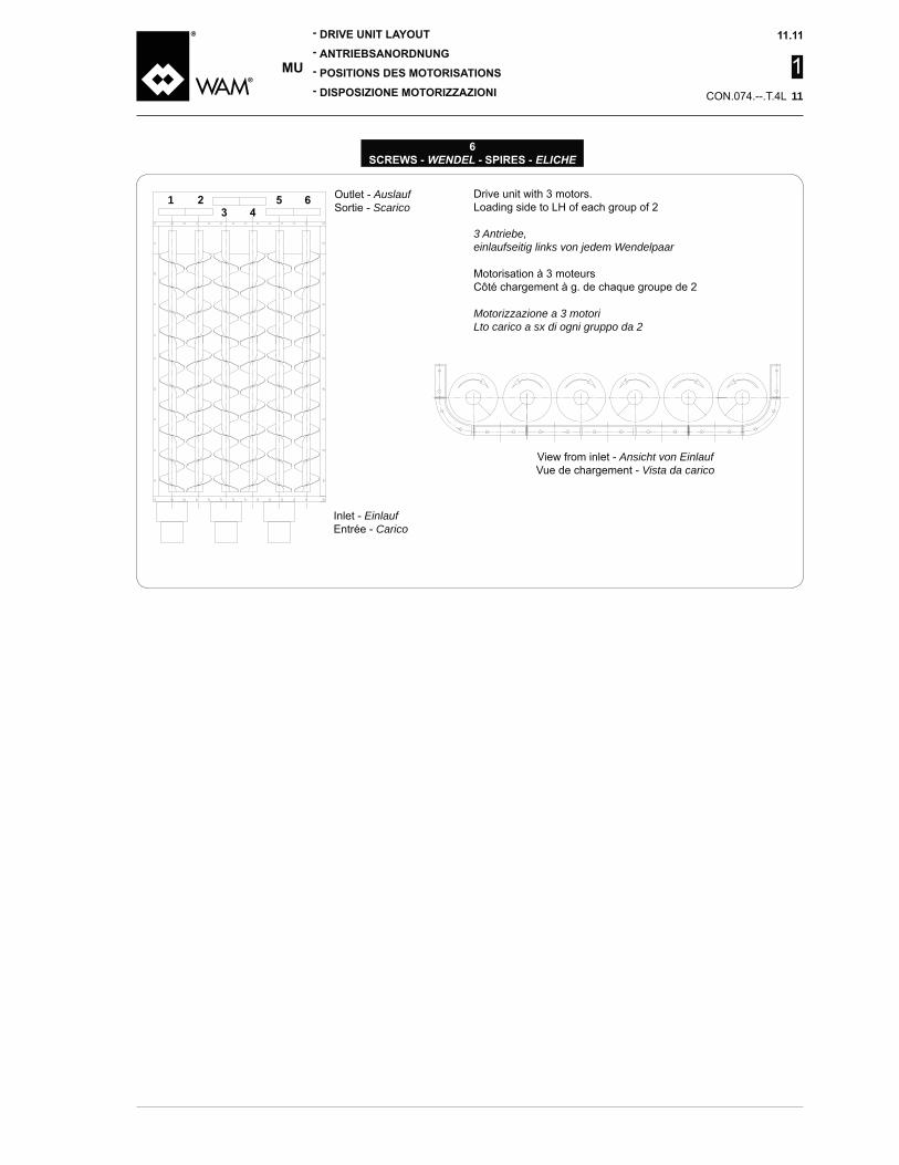
1 Drive unit with 3 motors.Loading side to LH of each group of 2
3 Antriebe,einlaufseitig links von jedem Wendelpaar
Motorisation à 3 moteursCôté chargement à g. de chaque groupe de 2
Motorizzazione a 3 motoriLto carico a sx di ogni gruppo da 2
Outlet - AuslaufSortie - Scarico
Inlet - EinlaufEntrée - Carico
11
View from inlet - Ansicht von EinlaufVue de chargement - Vista da carico

1
Finishklasse der Schnecke - Classe di finitura coclea
Standard Standard Standard Standard
High quality Hochwertig Soignée Accurata
Farbton Wendel Tonalità spira
See COLOUR Table - Voir la table des TEINTES - Vedi tabella TONALITA'
Oberflächenbehandlung WendelTrattamento superficiale spira
None Keine Aucun Nessuno
Sa 2.5 +80μm repaintable powder coat(RAL 7001 only)
Sa 2.5 +80μm Pulverbeschichtungüberlackierbar(nur RAL 7001)
Sa 2,5 +80μm reprise par peinture enpoudre possible(RAL 7001 seulement)
Sa 2.5 +80μm verniciatura a polvereriverniciabile(solo RAL 7001)
Sa 2.5 +80μm powder coat(all RAL hues)
Sa 2.5 +80μm Pulverbeschichtung(alle RAL-Farbtöne)
Sa 2,5 +80μm peinture en poudre(toutes les RAL)
Sa 2.5 +80μm verniciatura a polvere(tutti i RAL)
Sa 2.5 +120μm powder coat(all RAL hues)
Sa 2.5 +120μm Pulverbeschichtung(alle RAL)
Sa 2,5 +120μm peinture en poudre(toutes les RAL)
Sa 2.5 +120μm verniciatura a polvere(tutti i RAL)
VSa 2.5 +80μm food-grade powder coat
Sa 2.5 +80μm lebensmittelltauglichePulverbeschichtung
Sa 2,5 +80μm peinture en poudrealimentaire
Sa 2.5 +80μm verniciatura a polverealimentare
**
Sa 2.5 +
80μm powder coat(all RAL hues)
Sa 2.5 +80μm Zinkstaubanstrich +80μm Pulverbeschichtung(alle RAL-Farbtöne)
Sa 2.5 +
80μm peinture en poudre(toutes les RAL)
Sa 2.5 +
80μm verniciatura a polvere(tutti i RAL)
Oberflächenbehandlung Trog und DeckelTrattamento superficiale truogolo e coperchi
None Keine Aucun Nessuno
Sa 2.5 +80μm repaintable powder coat(RAL 7001 only)
Sa 2.5 +80μm überlackierbare Pulverbeschichtung(nur RAL 7001)
Sa 2.5 +80μm reprise avec peinture enpoudre possible(RAL 7001 seulement)
Sa 2.5 +80μm verniciatura a polvereriverniciabile(solo RAL 7001)
Sa 2.5 +80μm powder coat(all RAL paint hues)
Sa 2.5 +80μm Pulverbeschichtung(alle RAL-Töne)
Sa 2.5 +80μm peinture en poudre(toutes les RAL)
Sa 2.5 +80μm verniciatura a polvere(tutti i RAL)
Sa 2.5 +120μm powder coat(all RAL paint hues)
Sa 2.5 +120μm Pulverbeschichtung(alle RAL-Töne)
Sa 2.5 +120μm peinture en poudre(toutes les RAL)
Sa 2.5 +120μm verniciatura a polvere(tutti i RAL)
VSa 2.5 +80μm food-grade powder coat
Sa 2.5 +80μm lebensmittelechte Pulverbeschichtung
Sa 2.5 +80μm peinture en poudrealimentaire
Sa 2.5 +80μm verniciatura a polverealimentare
**
Sa 2.5 +
80μm powder coad(all RAL paint hues)
Sa 2.5 +80μm Zinkstaubanstrich +80μm Pulverbeschichtung(alle RAL-Töne)
Sa 2.5 +
80μm peinture en poudre(toutes les RAL)
Sa 2.5 +
80μm verniciatura a polvere(tutti i RAL)
Farbtöne Trog und Deckel Tonalità truogolo e coperchi
See COLOURS' Table - Voir la table des TEINTES - Vedi tabella TONALITA'
e la tonalità interna del truogolo e coperchi NON POTRA’ ESSERE DIVERSA da quella esterna.
The type of surface treatment and internal colour of the trough and covers MUST NOT be different from the external paint.
Der Typ der Oberflächenbe-handlung und der Tonalität im Troginneren und der Deckel KANN NICHT VON der externen
et les teinte interne de l’auge et des couvercles NE POURRA PAS ETRE DIFFERENTE de la teinte extérieure.

1
®
1) Portasupporto, testate motrici, supporti di estremità e basamenti per le trasmissioni sono verniciati con vernice ALTO SOLIDO RAL
2) Tutti i tipi di trattamenti a polvere (S,T,U,V,X) sono idonei per lavora-
max di 170°C.3) la verniciatura tipo T è idonea per
lavorare a contatto con cereali e farine, o comunque alimentari solidi in quanto sono formulati
lavorare a contatto con prodotti alimentari secondo quanto previsto
aggiornamenti derivati da direttive 2001/62/CE, 2002/16/CE, 2002/17/CE.
5) CAV 600 sarà verniciata a liquido
6) Per verniciature diverse da quelle indicate, contattare il Costruttore.
®
1) End plate, gear reducers, end bear-ings and drive bases are painted using HS paint such as RAL 5010 (gentian blue)
2) All types of powder treatment (S, T, U, V, X) are suitable for use in applications with max. temperature of 170°C.
3) T type painting is suitable for parts working in contact with cereals and
they are formulated in accordance
working in contact with food prod-ucts according to the provisions of
updates derived from Directives 2001/62/EC, 2002/16/EC, 2002/17/EC.
5) CAV 600 will be liquid-painted (see
6) For painting other than that indi-cated, contact the Manufacturer.
®
1) Zwischenlagerträger, Antriebsköp-fe, Endlager und Konsolen für die Getriebe sind mit HOCHFESTEM
-kiert.
2) Alle Arten der Pulverbeschichtung (S,T,U,V,X) eignen sich für Anwen-dungen mit max. Temperatur von 170°C.
3) Die Lackierung Typ T eignet sich -
treide und Mehl oder auf jeden Fall mit festen Nahrungsmitteln, weil
-
Nr. 338 konform sind.
-
-rungen aufgrund der Richtlini-en 2001/62/EG, 2002/16/EG, 2002/17/EG.
6) Für unterschiedliche Lackierungen muss man sich an den Hersteller wenden.
®
1) Porte palier, têtes motrices, paliers d’extrémité et bâtis pour les trans-missions sont peintes unique-ment avec des peintures A HAUT EXTRAIT SEC RAL 5010 (bleu gentiane).
2) Tous les types de traitements en poudre (S,T,U,V,X) sont indiqués pour travailler dans des applica-tions à une température maximum de 170°C.
3) la peinture type T est indiquée pour travailler en contact avec des cé-réales, des farines ou des produits alimentaires solides car formulées
travailler en contact de produits alimentaires conformément aux
et mises à jours successives tirées des directives 2001/62/CE, 2002/16/CE, 2002/17/CE.
5) CAV 600 sera peint à liquide (voir
6) Pour des peintures différentes de
le Constructeur.
Serienmäßig (immer auf Lager vorrätig)Di serie (sempre disponibili a magazzino)
Caterpillar yellow - Gelb Caterpillar - Giallo caterpillar
RAL 7001
Serienmäßig schnell (immer auf Lager vorrätig)Standard veloce (sempre disponibili a magazzino)
None - Keine - Aucun - Nessuno
RAL 1013
RAL 1015
E RAL 5015
F RAL 6011
RAL 7035
RAL 7032
L
RAL 1006
)Standard langsam (von Fall zu Fall zu erwerben, unterliegen Mindestbestellmengen)
Standard lenta (acquistati di volta in volta, soggetti a quantitativo minimo)
1 Yellow C - Gelb C - Giallo C
RAL 5012
RAL 5010
V Others - Andere - Autres - Altri RAL

1
Querschnitt Sezione
Werkstoffe MaterialeFe
1.4301 - Aisi 304L316L st. st. - 1.4401 - Inox 316L - Aisi 316L
AußenwendelEsterno elica
Ø
Wendel - Eliche
Innenrohr - Tubo interno
Länge Lunghezza
FL - FL
Länge offener TeilLunghezza parte aperta
Trennvorrichtung - Separatore+ = without - ohne - sans - senza
= with - mit - avec - con
Ausgestattet mit AbdeckungDotazione coperchio
+ = without cover - ohne Abdeckung - sans couvercle - senza coperchio = with cover - mit Abdeckung - avec couvercle - con coperchio
Einlauftyp Tipo bocca carico+ = without - ohne - sans - senza
= square - - carrée -
Länge konischer AbschnittLunghezza tratto conico
(+ + + )
+ + +
+ = without hatch - ohne Klappe - sans trappe - senza portello = with hatch - mit Klappe - avec trappe - con portello
SicherheitsklappePortello di sicurezza
VerdrägungselementInserto tubolare
+ = without - ohne - sans - senza = with - mit - avec - con

1
E
AntriebsanordnungPosizione motorizzazione
C = inlet end - einlaufseitig - côté d’entrée - codaT = outlet end - auslaufseitig - côté de sortie - testa
UntersetzungsverhältnisRapporto di riduzione
Getriebe Riduttore
S21 - S23 - S25 - S27
Typ KraftübertragungTipo di trasmissione
+ = direct - direkt - directe - direttaL = coupling - Kupplung - accouplement - giunto
= chain - Kette - chaîne - catena = chain - Kette - chaîne - catena = chain - Kette - chaîne - catena = chain - Kette - chaîne - catena = belt - Riemen - courroie - cinghia = belt - Riemen - courroie - cinghia = belt - Riemen - courroie - cinghia
V = belt - Riemen - courroie - cinghia
Frequenz Frequenza
++ = non WAM
Leistung Potenza
Pole Poli
BetriebsspannungTensione di alimentazione
+++ = no WAM
Position KonsolePosizione basamento
Direct driveDirektantriebEntraînement directTrasm. diretta
= without - ohne - sans - senza
RiementriebEntraînem. par courroieTrasm. cinghiaDrive CouplingKupplungsantriebEntraînem. par accoupl.Trasm. giunto
= high - oben - en haut - in alto
= in line - - en ligne - in linea
Chain driveKettenantriebEntraînem. par chaîneTrasm. catena
= north - Norden - nord - nord = south - Süden - sud - sud
E = east - Osten - est - estW = west - Westen - ouest - ovest
Antriebs - Motorizzazioni

1
Einlauf-Wälzlager Cuscinetto carico+ = without - ohne - sans - senza
= radial + thrust - radial/axial - radial-axial - radiale-assialeE = Orientable roller bearing - Pendelrollen - orientable à rouleau - orientabile a rullo
Wellenende EinlaufEstremità albero carico
+ = without - ohne - sans - senzaV = extending - vorstehend - en saillie - sporgente
= not extending - gekappt - pas en saillie - non sporgenteW = extending bored - vorstehend, gebohrt - en saillie, percé - sporgente forato
= not extending bored - nicht vorstehend, gebohrt - pas en saillie, percé - non sporgente for.
Auslauf-WälzlagerCuscinetto scarico
+ = without - ohne - sans - senza = radial - radial - radial - radiale
E = Orientable roller bearing - Pendelrollen - orientable à rouleau - orientabile a rullo
EndlagereinheitSupporto d’estremità
= std (P) = without grease cup - ohne Schmiernippel
sans graisseur - senza ingrassatore= INOX= without grease cup - ohne Schmiernippel
sans graisseur - senza ingrassatore = std (E)= without grease cup - ohne Schmiernippel
sans graisseur - senza ingrassatore
Wellenende AuslaufEstremità albero scarico
Endwellenzapfen Albero estremità
+ = without - ohne - sans - senzaV = extending - vorstehend - en saillie - sporgente
= not extending - nicht vorstehend - pas en saillie - non sporgenteW = extending bored - vorstehend, gebohrt - en saillie, percé - sporgente forato
= not extending bored - nicht vorstehend, gebohrt - pas en saillie, percé - non sporgente forato
035 = Ø 35 mm (150-200)
065 = Ø 65 mm (500-600)080 = Ø 80 mm100 = Ø 100 mm
Externe Dichtung - Tenuta esterna
Wellenverbingung Einlauf - Accoppiamento carico
Wellenverbindung Auslauf - Accoppiamento scarico
Wendeltyp - Tipo spira
Werkstoffe MaterialeFe
1.4306 - Aisi 304L316L st. st. - 1.4404 - Inox 316L - Aisi 316L
Länge Paddelwendel (bei gemischter Wendel)Longueur section à palettes (si spire mixte) - Lunghezza tratto a palette (se spira mista)
Bei gefüllter Schneckenwendel Con elica piena = Feeder paddle - Austragpaddel - Palette extractrices - Paletta estrattrici = Conveyor paddle Palette convoyeuses - Paletta convogliatrici = Combined - gemischt - Mixte - Mista

1
DIRECT
COUPLING
CHAIN
mmVery Free Flowing
Mildly ModeratelyFree Flowing Average
ExtremelyPoorly
μm [ t/m3 ]
FlowabilityAbrasivenessTemperature [ C° ]
(m3/h)
[ m ][ mm ][ ]
Diameter on RequestInlet spout lengthOutlet spout
fromfrom
toto
L =
ø T =L1 =C = Std Special
Continuous
Type of Plant
Hours/Day
Start ups/Hour
Days/Year
Hours/DayIndoor Outdoor
Drive PositionVoltage [ V ]
Inlet Outlet
50 60
1
mmsehr hoch
niedrig mittelmäßighoch mittelmäßig
hochschwach
μm [ t/m3 ]
Rieselfähigkeit
AbrasivitätTemperatur [ C° ]Risikoeigenschaften
3/h ]Höhe Materialsäule [ m ]
[ mm ] [ ]
Durchmesser (Wunsch)
Länge Einlauf Auslauf
VonVon
bisbis
L =
ø T =L1 =C = Standard
DauerbetriebChargenbetriebAnlagenaufstellung
Stunden pro Tag
Einsch. pro Std. Stunden pro Tagim Gebäude im Freien
PositionSpannung [ V ]
Einlauf Auslauf
50 60
DIRECT
COUPLING
CHAIN

1
mm
Moyenne ModéréeFluide Moyenne
ExtrêmeStagnante
μm [ t/m3 ]
FluiditéAbrasivitéTempérature [ C° ]Propriétés ou dangers
[ m3/h ]
[ m ][ mm ][ mm ]
Diamètre (si demandé)Longu. bouche entrée
DeDe
àà
L =
ø T =L1 =C = Std Spécial
ContinuDiscontinuType d’installation
Heures par jourDémar./heure Heures par jour
Intérieur Extérieur
Pos. motorisationTension [ V ]
Chargt. Déchargt.
50 60
DIRECT
COUPLING
CHAIN

1
mmMolto alta
MediaAlta Media
AltaScarsa
μm[ t/m3 ]
AbrasivitàTemperatura [ C° ]Proprietà a rischio
[ m3/h ]
[ m ][ mm ][ ]
Diametro se richiestoLungh. bocca carico
DaDa
aa
L =
ø T =L1 =C = std Speciale
ContinuoDiscontinuoTipo di impianto
Ore al giorno
Avvi l’ora
Giorni l’anno
Ore al giornoInterno Esterno
Tensione [ V ]
Carico Scarico
50 60
DIRECT
COUPLING
CHAIN

1
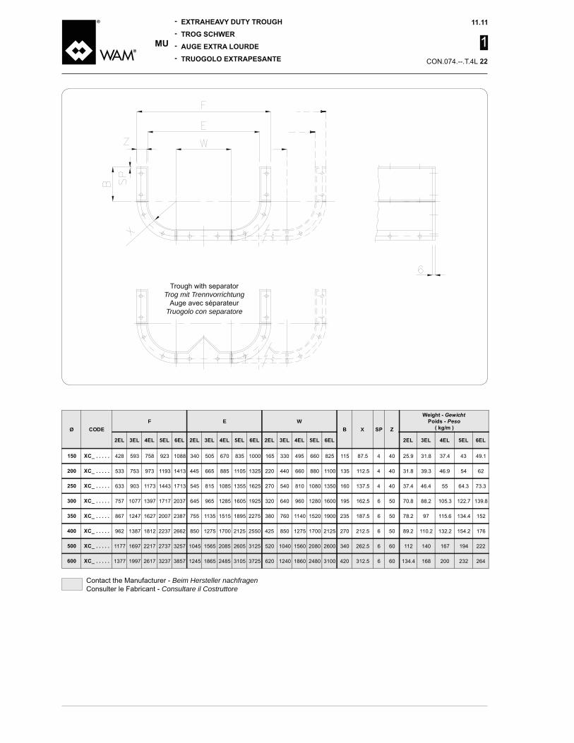
ØF E W
X
GewichtPeso
756 1086 505 670 835 1000 165 330 660 825 115 87.5 3 28.1 32.3 36.8
531 751 665 885 1105 1325 220 660 880 1100 135 112.5 3 35.2
631 1171 1711 815 1085 1355 1625 270 810 1080 1350 160 137.5 3 28.1 55
753 1073 1713 1285 1605 320 1280 1600 162.5 50 58.8 70.2 81.8
863 1623 2003 2383 755 1135 1515 2275 380 760 1520 235 187.5 50 52.1 77.1 101
1383 1808 2233 2658 850 1275 1700 2125 2550 850 1275 1700 2125 270 212.5 50 73.5 88.1 103 117
Trough with separatorTrog mit Trennvorrichtung
Auge avec séparateurTruogolo con separatore
1
ØF E W
X
GewichtPeso
758 1088 505 670 835 1000 165 330 660 825 115 87.5 31.8
533 753 665 885 1105 1325 220 660 880 1100 135 112.5 31.8 62
633 1173 1713 815 1085 1355 1625 270 810 1080 1350 160 137.5 55 73.3
757 1077 1717 2037 1285 1605 320 1280 1600 162.5 6 50 70.8 88.2 105.3 122.7
867 1627 2007 2387 755 1135 1515 2275 380 760 1520 235 187.5 6 50 78.2 115.6 152
1387 1812 2237 2662 850 1275 1700 2125 2550 850 1275 1700 2125 270 212.5 6 50 110.2 132.2 176
1177 2217 2737 3257 1565 2085 2605 3125 520 1560 2080 2600 262.5 6 60 112 167 222
1377 2617 3237 3857 1865 3105 3725 620 1860 3100 312.5 6 60 168 200 232
Trough with separatorTrog mit Trennvorrichtung
Auge avec séparateurTruogolo con separatore
Contact the Manufacturer - Beim Hersteller nachfragenConsulter le Fabricant - Consultare il Costruttore
1
Ø
560 725 1055
500 720 1160 1380
600 870 1680
705 1025 1665
825 1205 1585
1350 1775 2200 2625
1120 2160 2680 3200
1320 2560 3180 3800
Pitc
hes
- Tei
lung
von
- P
as d
e - P
assi
da
250m
m ±
0.5

1
Screws - WendelHélices - Eliche
N°
= section - section - sezione UV = section - section - sezione V
Ø J
GewichtPeso
763 115 260 30 6 50 25 7 10 12.6 18
535 755 135 185 320 30 6 50 25 10.3 18.7 23 27
635 1175 1715 160 215 375 6 50 70 30 20.7 26.7 32.8
755 1075 1715 2035 6 50 70 30 28 53
865 1625 2005 2385 235 275 510 8 50 70 30 62.3
1815 2665 270 305 575 8 60 80 37.5 61.8 80.5 118
1175 2215 2735 3255 380 720 50 10 60 37.5 80 115 150 186 221
1375 2615 3235 3855 885 55 10 60 100 37.5 112 163 213

1
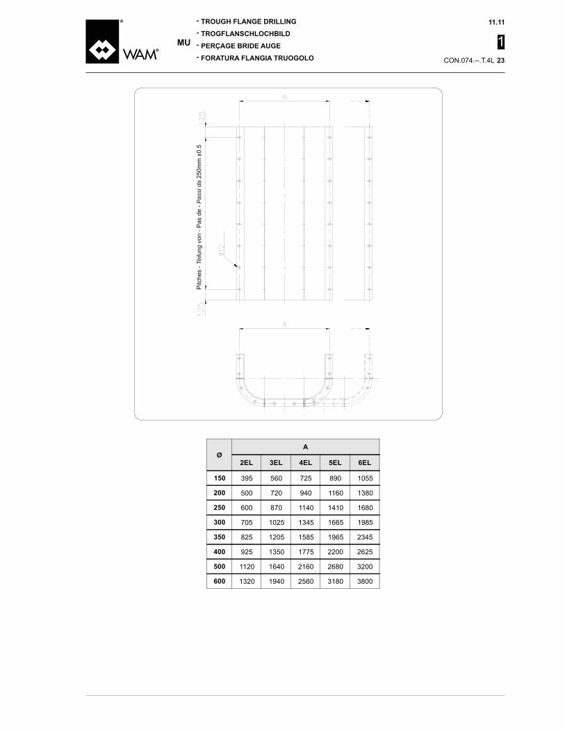
Lochbild oberer und unterer FlügelForatura ala superiore ed inferiore
Lower wing - Aile inférieure - Ala inferiore
Upper wing - Aile supérieure - Ala superiore
Ø
150 12.5 12.5 560 80 725 112.5 1055 127.5
200 12.5 15 500 100 720 110 120 1160 130 1380
250 12.5 15 600 100 870 135 120 105 1680
300 12.5 705 102.5 1025 112.5 122.5 1665 132.5
350 12.5 825 112.5 1205 102.5 1585 82.5 122.5
12.5 112.5 1350 125 1775 87.5 2200 100 2625 112.5
500 15 1120 110 120 2160 2680 3200 100
600 15 1320 110 120 2560 3180 3800 100
* Only outer drillings of lower wing - Trous extérieurs de l’aile inférieure seulement - Solo fori esterni dell’ala inferiore

1
WendelEliche
E F I L
2 70
50 25 30 266 230
2
115 172.53 560 80 52.5 505
725 112.5 85 670 763 55 67.5 835 76 1055 127.5 100 1000 8
Wendel Eliche
E F I L
2 500 100 72.5 535
50 25 30 316 280
3
222.53 720 110 82.5 665 755 5
120 885 75 1160 130 102.5 11056 1380 112.5 1325 11
INLET
CC
N x
100
mm
H
DA
N x
100
mm
125
H
B
PASSI/PITCH 250
B
D A E
M
PP P
BN
x 1
00 m
m
�12.5
B
L
IQ
�12.5
E
F G

1
Wendel Eliche
E F I L
2 705 102.5 72.5 755
50 60 30 385
5
128.3 3153 1025 112.5 102.5 1075 8
122.5 1285 115 1665 132.5 102.5 1605 17056 112.5 2033 17
Wendel Eliche
E F I L
2 600 100 72.5 635
50 60 30 376 330 110 262.53 870 135 107.5 815 6
120 1085 11755 105 77.5 1355 126 1680 62.5 1625 1715 15
Wendel Eliche
E F I L
2 825 112.5 77.5 755 865
50 60 30
6
3653 1205 102.5 67.5 1135 10
1585 57.5 1515 16255 82.5 2005 186 122.5 87.5 2275 2385 21
Wendel Eliche
E F I L
2 112.5 75 850
60 70 37.5 553 500
7
1003 1350 125 87.5 1275 11
1775 87.5 50 1700 1815 165 2200 100 62.5 2125 206 2625 112.5 75 2550 2665
Wendel Eliche
E F I L
2 1120 110 72.5 1175
60 70 37.5 50 668 600 120 512.53 120 82.5 1565
2160 130 2085 22155 2680 102.5 2605 27356 3200 100 62.5 3125 3255 30
Wendel Eliche
E F I L
2 1320 110 72.5 1375
60 70 37.5 55 773 700
11
607.53 120 82.5 1865 17
2560 130 2615 235 3180 102.5 3105 32356 3800 100 62.5 3725 3855 36

1

1
LH Screw - Linker Schneckenwendel - Spire Gauche - Spira Sinistra
RH Screw - Rechter Schneckenwendel - Spire Droite - Spira Destra
ØGewichte
Poids - Peso
150 XE..015..... 150 60 75 100 150 12
200XE..020.....
20060
100 133 200XE..020.....
250XE..025.....
25060
125 167 25015.8
XE..025.....
300XE..030.....
300 150 200 30025.8
XE..030..... 168 22
350XE..035.....
350 175 233 350XE..035..... 168 23.5
200 26631
168 27.5
500XE..050.....
500 250 333 50035.3
XE..050..... 168 31
600XE..060.....
600168
300 60051
XE..060.....
NotaI passi in tabella sono indicativi,
estensione dipendono dal prodot-
dell’apertura di carico.
Il peso è riferito alla spira con elica avente passo 1/1.
NoteThe pitch values in the Table are
extension depends on the product to be extracted and the length of the inlet opening.
The pitch refers to a screw with
AnmerkungDie Steigungen in der Tabelle sind unverbindlich. Das Vorhan-densein oder Nichtvorhandensein
-tragenden Produkt und der Länge des Einlaufs ab.
sich auf die Schneckenwendel mit Steigung 1/1.
RemarqueLes pas de la table sont indica-tifs, leur présence ou pas et leur extension dépendent du produit à extraire et de la longueur de l’ouverture de l’entrée de char-gement.
Le poids se réfère à la spire avec hélice ayant un pas 1/1.

1
ØGewichte
Poids - Peso
150 XE..015..... 150 60 75 100 150 12.7
200XE..020.....
20060
100 133 20015.5
XE..020..... 23.3
250XE..025.....
25060
125 167 25017.5
XE..025..... 25.5
300XE..030.....
300 150 200 30027.5
XE..030..... 168 23
350XE..035.....
350 175 233 350XE..035..... 168 25.5
200 266168
500XE..050.....
500 250 333 50038.5
XE..050..... 168
600XE..060.....
600168
300 60058.5
XE..060..... 50
LH Screw - Linker Schneckenwendel- Spire gauche - Spira Sinistra
RH Screw - Rechter Schneckenwendel - Spire droite - Spira Destra
NoteThe pitch values in the Table are
extension depends on the product to be extracted and the length of the inlet opening.
The pitch refers to a screw with
AnmerkungDie Steigungen der Tabelle sind unverbindlich. Das Vorhanden-sein oder Nichtvorhandensein und ihre Ausdehnung hängt vom
Länge des Einlaufs ab.
Das Gewicht ist auf die Schrau-benwendel mit Steigung 1/1
RemarqueLes pas de la table sont indica-tifs, leur présence ou pas et leur extension dépendent du produit à extraire et de la longueur de l’ouverture de l’entrée de char-gement.
Le poids se réfère à la spire avec hélice ayant un pas 1/1.
NotaI passi in tabella sono indicativi,
estensione dipendono dal prodot-
dell’apertura di carico.
Il peso è riferito alla spira con elica avente passo 1/1.

1
Material - WerkstoffMaterial - Materiale
Fe1.4306 - Aisi 304L
316L st. st. - 1.4404 - Inox 316L - Aisi 316L
Ø E F
505 670 835 1000 2 5 7 8 70 52.5 85 67.5 100 100 50 25 12.5 25
665 885 1105 1325 3 5 7 11 72.5 82.5 102.5 112.5 100 50 25 12.5 25
815 1085 1355 1625 6 12 15 72.5 107.5 77.5 62.5 120 60 30 60 12.5 30
1285 1605 5 8 11 17 75.5 102.5 102.5 112.5 120 60 30 60 12.5 30
755 1135 1515 2275 6 10 18 21 77.5 67.5 57.5 87.5 120 60 30 60 12.5 30
850 1275 1700 2125 2550 7 11 16 20 75 87.5 50 62.5 75 75 32.5 75 12.5 37.5
1565 2085 2605 3125 30 72.5 82.5 102.5 62.5 75 32.5 75 15.5 37.5
1865 3105 3725 11 17 23 36 72.5 82.5 102.5 62.5 75 32.5 75 15.5 37.5
Ø of screws - WendelzahlØ Hélices - Ø Eliche
U =V =
U 10 2 0X QType
Ø of screws - WendelzahlØ Hélices - Ø Eliche

1
Shape - BauformForme - forma X
EF
XFCC015....1 50 3.5 338 503 668 833 601 766 15 2 7.3 12.5 15.1 17.7
XFCC020....1 50 3.5 660 880 1100 1320 538 758 15 2 12.3 15.7 22.6
XFCC025....1 60 3.5 810 1080 1350 1620 1182 1722 15 2 10.5 18.6 22.7 26.7
XFCC030....1 60 1280 1600 762 1082 1722 15 2 15.3 21.6 27.8
XFCC035....1 60 750 1050 1350 1650 872 1252 1632 2012 15 2 17.6 31.6 38.6
70 1270 2120 1817 2667 15 2 27.6 35.8 52
XFCC050....1 70 1560 2080 2600 3120 1182 1702 2222 3262 15 2 23.6 33.7
XFCC060....1 70 1860 3100 3720 1382 2002 2622 3862 15 2 27.5 51.7 76
Shape - BauformForme - forma
Shape - BauformForme - forma

1
SCHRAUBVERSCHLUSS CHIUSURA A BULLONI
<
< <
<
DICHTUNG GUARNIZIONE
GASKETDICHTUNGGARNITUREGUARNIZIONE
XKH10. M10 X 25
2510TE0186
Farbe
Colore
WHITE - WEISSBIANCO

1
E1 F1 L
25 28 x 25 203 65 117 11 35 M10 8x7x36 5
35 252.5 310.5 58 85 105 137 13 35 M10 10x8x50 6.5
271.5 353.5 82 85 130 162 13 M12
55 60 x 55 386.5 82 151 110 210 18 55 M12 16x10x70 22
65 337.5 105 162 130 171 18 65 M16 32
80 130 180 60 170 250 22 82 M20 20x12x110 55
6210 6210 - 51110 22210CC 0.1 XUC 055
Wälzlager
Cuscinetti
Wälzlager
Cuscinetto
Fett
Grasso
Wellendichtung
Tenuta
<
Wälzlager
Cuscinetto
Z V

1
F1
F2
E2
EA
E2
L
DIN 6885
G
H
G3
ØC
E1
Ø D
3
E5
Ø D
2
Ø D
1
E6 F3
F2F1
Ø Ø Ø E1 F1Ø
25 70 50 10.5 162 55.5 2.5 10 117 11 8x7x36 M10 6
35 110 85 65 12.5 257.5 58 72.5 5.5 12 105 137 13 10x8x50 M10 8
130 100 78 16.5 226.5 308.5 82 12 130 162 13 M12 16
55 155 125 105 16.5 6 250.5 332.5 82 151 106.5 17.5 20 210 18 16x10x70 M12 26
65 155 125 105 16.5 6 263.5 368.5 105 162 106.5 17.5 20 171 18 M16 35
80 200 160 135 21 6 312 130 180 28 22 250 22 M20 62
100 235 160 25 6 561 165 230 135 38 25 266 30 107
6210 6210 - 51110 22210CC 0.1 XUC 055
6222 6222 - 51122 22222CC 0.6 XUC 115
Wälzlager
Cuscinetti
Wälzlager
Cuscinetto
Fett
Grasso
Wellendichtung
Tenuta
<
Wälzlager
Cuscinetto
ZV
Z
V

1
Ø ØE E1
�F1
Ø Für
Per
030 2 28 12 M8 20 120 70 50 0.5 S21
035 50 2 28 12 M8 20 120 70 50 0.65 XS.025
55 2 28 12 121.6 M8 20 80 60 0.75 S23
60 2 28 12 121.6 M8 20 80 60 0.8 XS.035
050 70 60 3 36 M10 30 100 70 1.2 S25
055 75 60 3 36 M10 30 100 70 1.5
060 80 60 3 36 M10 30 210 120 70 1.8 S27
070 60 3 36 M10 30 210 120 70 2 XS.055
080 100 62 3 36 210.7 M12 35 70 2.5 XS.065
100 120 80 3 36 18 210.7 M12 155 80 3 XS.080
115 85 50 18 M16 180 110 6.5 XS.100
K2
K3
ØD
ØF2
E3
ØC
E1
E
E2
F1 K1
Packung Baderna
standard:graphitiert
<

1
Internal pipe diameterInnenrohrdurchmesserDiamètre tube intérieurDiametro tubo interno
X 1
= Ø 150 - 200 - 250 = Ø 150 - 200 - 250
= Ø 500 = Ø 600
X 1
= Ø 150 - 200 - 250
= Ø 600
28 x 25 60 60 1.5
60 60 1.15
60 60 1
60 x 55 8.2
6.75
180 168 168 23

1
110 M12 XAV085T0601 3.1 / /
130 M16 XAV100T0601 / /
155 M16 / /
155 M16 6 / 13.2 /
200 M20 6 / 18 XAV160T1681 33
235 6 / 23.5 36.5
ØA
Ø
n° x ØD
ØT

1
A
ØE
C
G
L
ØN
ØM
F
ØD
K
ØP
H
Q
Q
= 1.1 - 1.5 kW = 2.2 - 3 kW
= splined / Vielkeil cannelée / calettata
à bride /
ratio - see catalogueUnters. - Siehe Katalograpp. - voir cataloguerapp. - vedi catalogo
1 1
= 0.75 kW = 1.1 - 1.5 kW = 2.2 - 3 kW
= splined / Vielkeil cannelée / calettata
bride /
ratio - see catalogueUnters. - Siehe Katalograpp. - voir cataloguerapp. - vedi catalogo
= 2.2 - 3 kW
= 11 - 15 kW = 18.5 - 22 kW
= splined / Vielkeil cannelée / calettata
à bride /
ratio - see catalogueUnters. - Siehe Katalog rapp. - voir cataloguerapp. - vedi catalogo
= 11 - 15 kW = 18.5 - 22 kW = 30 - 37 kW
= splined / Vielkeil cannelée / calettata
à bride /
ratio - see catalogueUnters. - Siehe Katalograpp. - voir cataloguerapp. - vedi catalogo

1
N.B.: Wenn Getriebe auf Schnecke montiert, Getriebe in enzianblau RAL 5010. Als Ersatzeil mit Grundanstrich.
N.B.: Montato sulla coclea è verniciato in Blu Genziana RAL 5010, come ricambio è verniciato in antiruggine.
Motorgröße
Gr. motore
F L
225 55.5 28 x 25 13 165 200 6 12 21.5 8 70 105 30
225 55.5 28 x 25 13 165 200 6 12 21 8 70 105 30
235 55.5 28 x 25 13 215 250 8 15 31 8 70 28 105 32
235 55.5 28 x 25 13 215 250 8 15 31 8 70 28 105 32
Motorgröße
Gr. motore
F L
276 128.5 72.5 13 165 200 8 12 27 10 85 110 130
286 128.5 72.5 13 215 250 8 15 31 10 85 110 28 130
286 128.5 72.5 13 215 250 8 15 31 10 85 110 28 130
128.5 72.5 13 265 300 10 15 10 85 110 28 130
Motorgröße
Gr. motore
F L
315 128.5 180 17 215 250 8 15 31 12 125 155 31 75
330 128.5 180 17 265 300 10 15 12 125 155 78
352 128.5 180 17 300 350 12 12 125 15580
352 128.5 180 17 300 350 51.5 12 125 155 51.5
Motorgröße
Gr. motore
F L
350 153.5 106.5 225 60x55 22 215 250 8 15 31 15 125 155 28 138
365 153.5 106.5 225 60x55 22 265 300 10 15 15 125 155 38
387 153.5 106.5 225 60x55 22 300 350 12 15 125 155
387 153.5 106.5 225 60x55 22 300 350 51.5 15 125 155
153.5 106.5 225 60x55 22 350 16 15 125 155 55 151

1
Lm
Ø P
Ø MF
D
E
L
Ø R
N
C
O
E F L
155 8 27 50 200 165 12.5 130 3.5 180 M25x1.5 1 25
155 8 27 50 273 200 165 12.5 130 3.5 180 M25x1.5 1 26
100 LR 180 28 8 31 60 306 250 215 15 180 218 M25x1.5 2
100 LH 180 28 8 31 60 306 250 215 15 180 218 M25x1.5 2 35
112 M 28 8 31 60 250 215 15 180 218 M32x1.5 2
112 M 28 8 31 60 250 215 15 180 218 M32x1.5 2
132 S 210 38 10 80 371 300 265 15 230 258 M32x1.5 2 65
132S 210 38 10 80 371 300 265 15 230 258 M32x1.5 2 65
132 M 210 38 10 80 300 265 15 230 258 M32x1.5 2
132 M 210 38 10 80 300 265 15 230 258 M32x1.5 2
132 ML 210 38 10 80 300 265 15 230 258 M32x1.5 2 87
11 160 M 255 12 110 350 300 250 5 300 2 118
160 MA 255 12 110 350 300 250 5 300 2 118
255 12 110 350 300 250 5 300 2 118
160 L 255 12 110 350 300 250 5 300 2
160 L 255 12 110 350 300 250 5 300 2
180 M 285 51.5 110 350 300 250 5 2 173
180 L 285 51.5 110 585 350 300 250 5 2 220
180 L 285 51.5 110 585 350 300 250 5 2 220
Cable gland is made of plastic.
seen standing behind fan. Cable gland below.*With different motor makes, a tolerance of ± 50 mm should be allowed.
When mounted on feeder
5010. As spare part only primer painted.
PG - Verschraubungen aus Kunst-stoff. Klemmenkasten auf der linken Seite von Lüfterhaube aus gese-hen. Kabeleintritte an der Unterseite des Klemmenkastens.
von ± 50 mm möglich.
Wenn Getriebe auf Schnek-ke montiert ist, Lackierung =
-teil nur mit Grundanstrich.
I pressacavi sono in plastica.La morsettiera si trova sul lato si-nistro del motore (visto dal carter).*Con marche diverse sono possi-
Montato sulla coclea è
5010; come ricambio è verniciato in antiruggine.
Presse-câbles en plastique.
du moteur (vu du carter). *Avec des marques diverses des tolérances de ± 50 mm sont possibles.
Monté sur la vis les moteurs
5010. Comme pièce de rechange en antirouille.

1
The motors listed in the table are WAM® models manufactured according to IEC as well as DIN standards as far as junction box connections are concerned.This means other electric motor makes can be used providing they conform to the above men-tioned standards without having to change the gear reducer.
WAM® motors are constructed in
Directive).- Low Voltage Directive 73/ 23/EEC.
- Isolation class F- Motor protection IP 55- Terminal protection IP 55
(inclusive)
22 kW.
- single Dahlander type winding
WAM® motors can withstand a
can operate at environmental temperatures varying from -10°
If motors with special technical characteristics are required (volt-age, cycles, double speed etc.) please contact a WAM® sales
For further details and character-istics see electric motor catalogue WA.052MT
Die in der Tabelle aufgeführten Elektro-Flanschmotoren, Fabrikat WAM®, entsprechen der europä-ischen IEC-Norm sowie der DIN, was die Klemmenverbindun-gen betrifft. Dies ermöglicht es, wahlweise Normmotoren eines
ohne dabei die Getriebeeinheit
muss allerdings beachtet werden, dass WAM-Motoren als Ergebnis langjähriger Praxiserfahrungen die beste Garantie für einen
unterschiedlichsten Anwendungs-bereichen bieten.
Die WAM® Motoren entsprechen
- Niederspannungs-Richtlinie 73/23/EWG.
- Isolierstoffklasse F
-1
kW einschließlich
bis 22 kW.
-1
Die WAM® Motoren ertragen ei-
-
Sollte eine Sonderausführung
etc. erforderlich sein, bitte mit
Kontakt aufnehmen.
technische Daten siehe Katalog der Elektromotoren WA.052MT.
I motori riportati nella tabella sono di marca WAM® e sono conformi alle norme europee IEC nonchè alle norme DIN per quanto ri-guarda gli attacchi (pressacavi) nella morsettiera. Ciò significa
impiego di motori di qualsiasi mar-
dover cambiare testata motrice.
I motori WAM® sono costruiti
EMC).- Le direttive basso voltaggio
73/23/EEC.
- Classe isolamento F
kW compresi
22 kW.
- unico avvolgimento tipo Dahlan-der
I motori WAM® possono resistere
possono lavorare ad una tempe-ratura ambiente che varia da -10°
Qualora dovesse essere neces-sario l’impiego di un motore con caratteristiche diverse (voltaggio,
pregati di contattare il ns. uff. tecnico commerciale.
Per ulteriori dettagli e caratteristi-che tecniche vedi catalogo motori elettrici WA.052MT.
Les moteurs listés dans le tableau sont de la marque WAM® et sont en conformité avec les normes européeues IEC et DIN en ce qui concerne les connexions dans la
l’utilisateur a la possibilité d’utili-ser des moteurs de quelconque marque, pourvu qu’ils soient conformes aux normes, sans devoir changer la tête motrice.
Les moteurs WAM® sont construits
-tive EMC).- Aux directives basse tension 73/23/EEC.
bride- Classe d’isolation F- Protection moteur IP 55- Protection bornier IP 55
kW inclus
22 kW.
- enroulement unique type Da-hlander
tr/mn
Les moteurs WAM® peuvent résister à un taux d’humidité de
température ambiante qui varie de
S’il était nécessaire d’utiliser un moteur avec des caractéristiques différentes (voltage, fréquence, polarité etc.) vous êtes priés de contacter notre bureau commer-ciaux.
Pour plus de details et caracté-ristiques consulter le cataloque moteur électriques WA.052MT

1
Internal pipe diameterInnenrohrdurchmesserDiamètre tube intérieurDiametro tubo interno
= Ø 558 = Ø 660
X L 1
=
= Ø 660
28 x 25 65 35 M 10
28 x 25 65 35 M 10 0.65
60 35 M 12 60 1.15
60 M 16 60 1
60 x 55 55 M 16 8.2
65 M 20 6.75
180 168 82 168 23
1
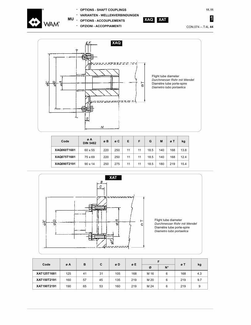
Flight tube diameterDurchmesser Rohr mit WendelDiamétre tube porte-spireDiametro tubo portaelica
Flight tube diameterDurchmesser Rohr mit WendelDiamétre tube porte-spireDiametro tubo portaelica
E F
60 x 55 220 250 11 11 18.5 168 13.8
220 250 11 11 18.5 168
250 275 11 11 18.5 180
F
Ø
125 31 105 168 M 16 6 168
160 57 135 M 20 6
65 53 160 6

1
250 35 280 500 375 215 160
NotaIl numero delle trasmissioni pre-
Costruttore
RemarqueLe nombre des entraînements
avec le Fabricant
AnmerkungDie Zahl der Getriebe auf der
NoteThe number of transmissions present in the MU must be de-fined in accordance with the Manufacturer.

1
A
C
D
300 1105 880 1350
NotaIl numero delle trasmissioni pre-
Costruttore
RemarqueLe nombre des entraînements
avec le Fabricant
AnmerkungDie Zahl der Getriebe auf der
NoteThe number of transmissions present in the MU must be de-fined in accordance with the Manufacturer.

1
Palette trapezie tipo A1 - N° 3 palette al passo
LH Screw - Linker Schneckenwendel - Spire gauche - Elica sinistra
RH Screw - Rechter Schneckenwendel - Spire droite - Elica destra
Ø
150 60 100 116 100
200 60 100 122 133
250 60 125 155 167
300 150 185 200
350 175 215 233
200 267
500 250 305 333
600 168 300 365
Contact the Manufacturer - Beim Hersteller nachfragenConsulter le Fabricant - Consultare il Costruttore

1
E1 F1
25 28 x 25 203 65 117 11 M10 8x7x36 5
35 252.5 310.5 58 85 105 137 13 M10 10x8x50 6.5
271.5 353.5 82 85 130 162 13 M12
55 60 x 55 386.5 82 151 110 210 18 M12 16x10x70 22
65 337.5 105 162 130 171 18 M16 32
80 130 180 60 170 250 22 M20 55
6206 - 2RS 6206 - 2RS / XUC 035
6206 - 2RS 6210 - 2RS / XUC 055
6206 - 2RS 6212 - 2RS / XUC 070
6206 - 2RS 6218 - 2RS / XUC 100
Wälzlager
Cuscinetti
Wälzlager
Cuscinetto
Wellendichtung
Tenuta
<
Wälzlager
Cuscinetto
Z V
G3

1
Ø Ø Ø E1 F1Ø
25 70 50 10.5 162 55.5 2.5 10 117 11 8x7x36 M10 6
35 110 85 65 12.5 257.5 58 72.5 5.5 12 105 137 13 10x8x50 M10 8
130 100 78 16.5 226.5 308.5 82 12 130 162 13 M12 16
55 155 125 105 16.5 6 250.5 332.5 82 151 106.5 17.5 20 210 18 16x10x70 M12 26
65 155 125 105 16.5 6 263.5 368.5 105 162 106.5 17.5 20 171 18 M16 35
80 200 160 135 21 6 312 130 180 28 22 250 22 M20 62
100 235 160 25 6 561 165 230 135 38 25 266 30 107
F1
F2
E2
EA
E2
L
DIN 6885
G
H
G3
ØC
E1
Ø D
3
E5
Ø D
2
Ø D
1
E6 F3
F2F1
6206 - 2RS 6206 - 2RS / XUC 035
6206 - 2RS 6210 - 2RS / XUC 055
6206 - 2RS 6212 - 2RS / XUC 070
6206 - 2RS 6218 - 2RS / XUC 100
6222 - 2RS 6222 - 2RS / XUC 115
Wälzlager
Cuscinetti
Wälzlager
Cuscinetto
Wellendichtung
Tenuta
<
Wälzlager
Cuscinetto
VZ
Z
V

1
Ø E FL
1 60 3 175 251 230 115 763 505 670 835 1000 560 725 1055 2 5 7 8 80 112.5 127.5
2 60 3 225 311 280 535 755 665 885 1105 1325 500 720 1160 1380 3 5 7 11 100 110 120 130
2 60 3 275 361 330 110 635 1175 1715 815 1085 1355 1625 600 870 1680 6 12 15 100 135 120 105
2 60 325 385 128.3 755 1075 1705 2035 1285 1605 705 1025 1665 5 8 11 17 102.5112.5122.5172.5
3 80 375 865 1625 2005 2385 755 1135 1515 2275 825 1205 1585 6 10 18 21 112.5102.5 82.5 122.5
3 80 5 535 500 100 1815 2665 850 1275 1700 2125 2550 1350 1775 2200 2625 7 11 16 20 112.5 125 87.5 100 112.5
80 5 525 655 600 120 1175 2215 2735 3253 1665 2085 2605 3125 1120 2160 2680 3200 30 110 120 130 100
80 5 625 755 700 1375 2615 3235 3855 1865 3105 3725 1320 2560 3180 3800 11 17 23 36 110 120 130 100
Contact the Manufacturer - Beim Hersteller nachfragenConsulter le Fabricant - Consultare il Costruttore

1
-plied is provided with screws and nut. The inspection hatch is prear-ranged for limit switch or safety
ORDER
mount is required
mount are required
chiuso con viti e dadi. Il portello è predisposto per il
ORDINARE
corsa
inklusive Schrauben und Muttern geliefert. Die Inspektionsklappe ist für Endschalter oder Sicherheits-Endschalter Montage vorgerüstet.
Endschalter-
schalter
-nie avec des vis et des écrous. La trappe de visite est prédisposée pour commutateur de limite ou de montage interrupteur de sécurité limite.
COMMANDEZ-
support
ØE
F
50 338 503 668 833 601 766 15 560 725 1055 2
50 660 880 1100 1320 538 758 15 500 720 1160 1380 2
60 810 1080 1350 1620 1182 1722 15 600 870 1680 2
60 1280 1600 762 1082 1722 15 700 1015 1330 2
60 750 1050 1350 1650 872 1252 1632 2012 15 825 1205 1585 2
70 1270 2120 1817 2667 15 1350 1775 2200 2625 2
70 1560 2080 2600 3120 1182 1702 2222 3262 15 1120 2160 2680 3200 3
70 1860 3100 3720 1382 2002 2622 3862 15 1320 2560 3180 3800 3
Contact the Manufacturer - Beim Hersteller nachfragenConsulter le Fabricant - Consultare il Costruttore
1
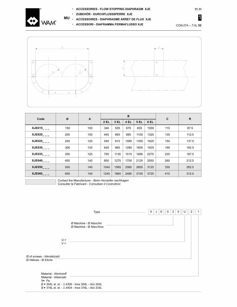
Ø
150 100 505 670 835 1000 110 87.5
200 100 665 885 1105 1325 130 112.5
250 120 815 1085 1355 1625 150 137.5
300 120 1285 1605 162.5
350 120 755 1135 1515 2275 230 187.5
850 1275 1700 2125 2550 260 212.5
500 1565 2085 2605 3125 330 262.5
600 1865 3105 3725 312.5
Ø Machine - Ø MaschinØ Machine - Ø Macchina
U =V =
U 2 10 2 0X EType
Ø of screws - WendelzahlØ Hélices - Ø Eliche
Material - WerkstoffMaterial - Materiale
Fe1.4306 - Aisi 304L
316L st. st. - 1.4404 - Inox 316L - Aisi 316L
Contact the Manufacturer - Beim Hersteller nachfragenConsulter le Fabricant - Consultare il Costruttore

1
Ø
XKX _ _ _ _ 758 1088 560 725 1055 350
XKX _ _ _ _ 533 753 500 720 1160 1380 350
XKX _ _ _ _ 633 1173 1713 600 870 1680 350
XKX _ _ _ _ 753 1073 1713 2033 705 1025 1665 350
XKX _ _ _ _ 867 1627 2007 2387 825 1205 1585 350
XKX _ _ _ _ 1387 1812 2237 2662 1350 1775 2200 2625 350
XKX _ _ _ _ 1177 2217 2737 3257 1120 2160 2680 3200 350
XKX _ _ _ _ 1377 2617 3237 3857 1320 2560 3180 3800 350
Contact the Manufacturer - Beim Hersteller nachfragenConsulter le Fabricant - Consultare il Costruttore
The grid under XKXIT IS NOT a safety device.It is meant only to prevent foreign bodies from penetrating inside the screw conveyor.
La griglia/rete sotto portello XKXNON è un componente di sicu-
Essa serve soltanto per evitare che, una volta aperto il portello, possano cadere nella coclea corpi estranei.
Das Gitter unter XKX IST KEINE Sicherheitsvorrich-tung. Es soll lediglich verhindern, dass Fremdkörper in die Förderschnek-ke eindringen.
La grille sous XKX N’EST PAS un dispositif de sécu-rité.Elle est destinée uniquement à empêcher les corps étrangers de pénétrer à l’intérieur du transpor-teur à vis.

1
* L = 500 - 1000 - 1500 - 2000 - 2500 - 3000 mm
Ø
150 175
200 225
250 275
300 325
350 375
500 525
600 625
U =V =
U 2 10 1 5X GType 1 0
L(dm)
Ø Machine - Ø MaschinØ Machine - Ø Macchina
Ø of screws - WendelzahlØ Hélices - Ø Eliche
Material - WerkstoffMaterial - Materiale
Fe1.4306 - Aisi 304L
316L st. st. - 1.4404 - Inox 316L - Aisi 316L
Contact the Manufacturer - Beim Hersteller nachfragenConsulter le Fabricant - Consultare il Costruttore

1
Ø
75 500
75 500
125 500
125 500
125 500
200 500
200 500
200 500
1Induktionssensor vom Lieferumfang ausgeschlossen
Sensore induttivo escluso dalla fornitura
The number of accessories required is equal to the number of screws
Il faut qu’il y ait autant d’accessoires que de nombre de spires
1
Contact the Manufacturer - Beim Hersteller nachfragenConsulter le Fabricant - Consultare il Costruttore
Number of screws
Nombre de spiresNumero di eliche
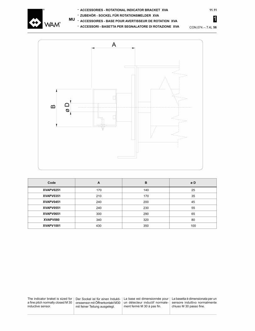
1
La basetta è dimensionata per un sensore induttivo normalmente
inductive sensor.
La base est dimensionnée pour un détecteur inductif normale-
Der Sockel ist für einen Indukti-
mit feiner Teilung ausgelegt.
ø D
A
170 25
210 170 35
200
230 55
300 65
320 80
350 100

1
Passend zu - Idoneo per
_ 030 S 21
_ 035 XS_025__
_ S 23
_ 113 XS_035__
_ 050 S 25
_ 055
_ 060 S 27
_ 070 158 XS_055__
_ 080 158 XS_065__
_ 100 203 XS_080__
1 116 55 238 XS_100__1
1 136 XS_120__1
X J
Plate in contact with productPlatte produktberührendPlaque en contact avec le produitPiastra a contatto con il prodotto
Werkstoff der produktberührenden PlatteMateriale piastra a contatto con il prodotto
Carbon steel - Normalstahl Acier au carbone - Acciaio al carbonio
1.4306 - Aisi 304L316L st. st. - 1.4404 - Inox 316L - Aisi 316L
- Tipo tenuta2 Water - Wasser - Eau5 Grease Graisse - Grasso6 Air - Luft - Air - Aria (0.2 bar)
1
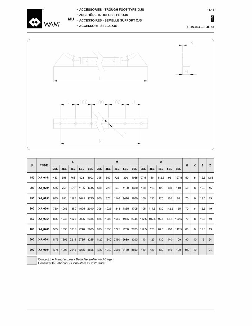
ØL
763 560 725 1055 80 112.5 127.5 50 5 12.5 12.5
535 755 500 720 1160 1380 100 110 120 130 50 6 12.5 15
635 1175 1715 600 870 1680 100 135 120 105 70 6 12.5 15
750 1065 1380 2010 705 1025 1865 1705 105 117.5 130 155 70 6 12.5
865 1625 2005 2385 825 1205 1585 112.5 102.5 82.5 122.5 70 8 12.5
1815 2665 1350 1775 2200 2625 112.5 125 87.5 100 112.5 80 8 12.5
1175 2215 2735 3255 1120 2160 2680 3200 110 120 130 100 10 15
1375 2615 3235 3855 1320 2560 3180 3800 110 120 130 100 100 10
Contact the Manufacturer - Beim Hersteller nachfragenConsulter le Fabricant - Consultare il Costruttore

1
Gli estrattori multipli devono essere sempre adeguatamente supportati.
-ri utili ad irrigidire la struttura e a facilitare l’opera di supporto spe-cialmente quando sugli estrattori gravano pesi elevati.
La geometria e la forma dell’MU sono dimensionati come sistema
quindi non è dimensionato per
fondo di una tramoggia, di un silo o di qualunque altro contenitore. Sarà cura dell’installatore suppor-tarlo correttamente.
Ø
Nbr. of screws - WendelzahlN° de spires - N° spire
Les extracteur multiples doivent toujours être soutenus de manière adéquate.Les anneaux de renforts sont des accessoires servant à maintenir la structure rigide et faciliter la fonc-tion de support surtout quand les extracteurs doivent soutenir des poids élevés.
La géométrie et la forme des extracteurs multiples à vis sont dimensionnés comme système pourl’extraction du produit. Les MU ne sont donc pas dimensionnés pour mener la fonction structurale de fond d’une trémie, ou d’un silo ou de n’importe quel autre type de récipient. Il est la responsabi-lité de l’installateur de supporter l’extracteur MU correctement.
Austragschneckenböden müs-sen immer in angemessener Weise gelagert werden.Die Verstärkungsringe sind Zu-
insbesondere dann, wenn ein hohes Gewicht auf den Schne-ckenwendeln lastet.
Geometrie und Form der MU Schneckenaustragsböden ent-sprechen allein der Anforde-
MU Schneckenaustragsböden sind nicht dafür ausgelegt, eine
erfüllen. Es liegt in der Verantwor-tung des Anlagenaufstellers, den
-
have adequate support.The reinforcement rings are ac-cessories used for stiffening the structure so that it provides support especially when the puller screws have to support very heavy weights.
Geometry and shape of MU Live
a material discharging device.
-port functions of a bin, hopper or
responsibility to support the silo, hopper or bin in a correct fashion.
Contact the Manufacturer - Beim Hersteller nachfragenConsulter le Fabricant - Consultare il Costruttore

1
Consultare il costruttore.
-bilità delle singole spire dal lato opposto a quello della MTR.
attraverso una apertura praticata sulla piastra portasupporti.
dover sconnettere alcuna parte dell’MU dalle strutture (tramog-ga, sostegni o altro) ad esso collegate.Gli accoppiamenti calettati faci-
di sfilo non dovendo operare all’interno dell’MU per togliere o svitare eventuali bulloni di ac-
Cette option permet l’extraction des spires par le côté opposé à celui de la MTR.
La spire est retirée dans la diec-tion axiale à travers une ouverture
L’opération est réalisable sans devoir désolidariser aucune partie de l’extracteur MU des structures (trémie, supports ou autre) qui lui sont réliées.Les accouplements emboîtés facilitent encore plus l’opération de dépose, car il ne faut pas intervenir à l’intérieur du MU pour enlever ou dévisser des boulons
par bride.
Mit dem Hersteller Kontakt aufnehmen
Diese Option ermöglicht das -
gegenüber dem Antrieb. Die Wendel wird axial durch eine
Lager-Endschild vorgesehen ist. Der Vorgang kann durchgeführt werden, ohne irgendein Teil des MU-Austragbodens von den mit ihm verbundenen Strukturen (Trichter, Träger u.ä.) abtrennen
Die Evolventenkeilwellenver-bin-dungen vereinfachen das
-ren ar-beiten muss, um etwa-
Contact the Manufacturer.
This option makes it possible to remove the screws separately from the opposite side of the MTR. The screw is extracted axially through an opening made on the end plate.The operation is possible without having to disconnect any part of the MU from the frame (hopper, supports, or other parts) con-nected to it.The splined couplings facilitate this removal further since it is not necessary to work inside the MU to remove or unscrew bolted or

1
Length L = (end flange to end multipla di 500 mm.
Länge L = (Endflansch-End-flansch) ist ein Vielfaches von 500 mm.
de 500 mm.
CA
L
L fürper
1500
ø 150
2000 1 1
2500 1 1
3000 1 1
3500 1 1
1 1
ø 200-2501 1
5000 1 1 1
5500 1 1 1
6000 1 1 1
6500 1 1 1 ø 300
L fürper
2000 1
ø 500
2500 1 1
3000 1 1
3500 1 1
1 1
1 1
5000 1 1
5500 1 1 1
6000 1 1 1
6500 1 1 1ø 600
7000 1 1 1

1
Ø LMAX
RMAX
TMAX
V
2EL 3EL 5EL 6EL
150 A + 200
700 650
500 650 850 1000 1200
200A + 230
600 850 1050 1250 1500
250 700 1250 1525 1800
300A + 270
1000
750 850 1160 1800 2100
350800
1000 1375 1750 2125 2500
A + 3001100 1525 2375 2800
500 1250 2325 2870
600 1000 1500 2125 2750 3375
rendersi necessario dividere -
port il peut s’avérer nécessaire de décomposer l’extracteur en plusieurs sections et avec le groupe de motorisation séparé.
kann es erforderlich sein, den Aus-tragboden in mehrere Teile
separate the puller screw into a number of sections, with the drive unit separated, for transport.

1
Pc
Pa
If the equipment is shipped in a packing case or crate add the weight of the packing to the weight of the equipment.
Se la macchina è spedita imbal-lata in cassa o gabbia, al peso totale della stessa aggiungere il peso dell’imballo.
Si la machine est expédiée em-ballée en caisse ou cage, ajouter le poids de l’emballage au poids
Wird das Gerät in einer Kiste oder
gebracht, ist das Gewicht der
= Total weight / Gesamtgewicht / Poids total / Peso totale (kg)L = Length / Länge / Longueur / Lunghezza (m)
= n° screws / n° Schneckenwendel \ n° spire \ Numero spire
Per macchine con n° di eliche superione a due ricavare i pesi dalla tabella sottostante.
1 1
1 = Total weight / Gesamtgewicht / Poids total / Peso totale (kg)L = Length / Länge / Longueur / Lunghezza (m)
= n° screws / n° Schneckenwendel \ n° spire \ Numero spire
For machines with more than two screws consult the tables below for the weights.
Für die Maschinen mit mehr als
-nehmen.
Pour les machines dont le nombre de spires est supérieur à deux, calculer le poids à partir de la table ci-dessous.
Ø
52.8 180 330 330
22.5 27.7 32.2 55.6 102
Ø
1 18.6 22.2 62.5 75 103 136
1 16.8 23.2 36.7 55 67

1
Pc
Pa
If the equipment is shipped in a packing case or crate add the weight of the packing to the weight of the equipment.
Se la macchina è spedita imbal-lata in cassa o gabbia, al peso totale della stessa aggiungere il peso dell’imballo.
Si la machine est expédiée embal-lée en caisse ou cage, ajouter le poids de l’emballage au poids total
Wird das Gerät in einer Kiste oder
gebracht, ist das Gewicht der
= Total weight / Gesamtgewicht / Poids total / Peso totale (kg)L = Length / Länge / Longueur / Lunghezza (m)
= n° screws / n° Schneckenwendel \ n° spire \ Numero spire
Per macchine con n° di eliche superione a due ricavare i pesi dalla tabella sottostante.
1 1
1 = Total weight / Gesamtgewicht / Poids total / Peso totale (kg)L = Length / Länge / Longueur / Lunghezza (m)
= n° screws / n° Schneckenwendel \ n° spire \ Numero spire
For machines with more than two screws consult the tables below for the weights.
Für die Maschinen mit mehr als
-nehmen.
Pour les machines dont le nombre de spires est supérieur à deux, calculer le poids à partir de la table ci-dessous.
Ø
58.8 106 160 252 500
35.8 71.3 80.6 111.3 132.5
Ø
1 25 71 83.8 110 226
1 55 60 70 85
Jamieson Equipment Companywww.jamiesonequipment.com
toll free 800.875.0280