Wallace & Tiernan® Disinfection Systems OSEC® Pool
71
Wallace & Tiernan® Disinfection Systems OSEC® Pool IM.85.051GE
Transcript of Wallace & Tiernan® Disinfection Systems OSEC® Pool

Wallace & Tiernan® Disinfection SystemsOSEC® Pool
IM.85.051GE


Siemens plc Siemens Division: Water Technologies
Address; Priory Works, Tonbridge, Kent, TN11 0QL, UK
Tel.: +44 (0) 1732 771 777 Fax.: +44 (0) 1732 771 800 www.siemens.co.uk/water
Registered office: Faraday House, Sir William Siemens Square, Frimley, Camberley, GU16 8QD. Registered no: 727817, England.
s Industry
IMPORTANT ANNOUNCEMENT Supply of Spares - Payment by Credit/Debit Card
Siemens Water Technologies are pleased to announce that we are able to accept payment for spare parts by major credit/debit cards. We appreciate that some of our Customers periodically require quantities of spare parts, possibly to repair plant breakdowns. Standard procedures, whereby an official order has to be issued before parts can be supplied, often hinders this process, leaving the operations/maintenance personnel frustrated and without vital spares to complete the job. If you, or your staff, have a valid credit/debit card, that is all you need. We will not require an official order to cover credit/debit card transactions. To order freephone 0800 7834628. Our staff will take all the details and advise you on price and availability of your parts requirements. Your order will be despatched the same day wherever possible (depending on the time the order is placed). If ordered late in the day, it will be despatched the next working day. An invoice will be sent to your designated invoice address with a copy of the credit payment slip for your records. We are sure that this “Fast Track” facility will be welcomed by your “sharp end” personnel who keep plant operational. G.Horden Sales & Marketing Director Chemical Feed and Disinfection


� FormRD1012,Issue3,June2007
Didwe…… ExcellentHighly
SatisfactorySatisfactory Unsatisfactory
HighlyUnsatisfactory
1 Treatyouinahelpful&friendlymanner?
2 Providesoundadvice,whichdemonstratesprofessionalismandknowledgeofyourapplication?
3 Provideproductsandservicesthatmeetyourrangeofchemicaldosing&disinfectionneeds?
4 Provideproductsandservicesofthequalitythatmeetsyourneeds?
5 Ifyouhaverecentlyreceivedaninstructionmanual,wasitclear&easytounderstand?
6 Ifyouhaverecentlyrequestedparts,werethosepartsavailable?
7 Ifwehaverecentlysuppliedequipmenttoyou,diditmeetitsstatedperformance?
8 Giveefficient,promptserviceandkeepyouuptodateonprogressofyourorder?
9 Arewetherewhenyouneedus–accessibleandsupportive?
10 Didwetakeownershipofanyproblemsthatmayhavearisen?
11 Overallhowdoyourateourservice?
MuchBetter
Better Thesame Worse MuchWorse
12 Comparedto12monthsago,howdoyourateourcompany’sperformance?
13 Comparedtootherequipmentcompanies,howdoyourateourservice?
Definitely Probably Undecided Probablynot Definitelynot
14 Wouldyourecommendourcompanytoacolleague?
CUSTOMER FEEDBACKInlinewithourISO9001QualityProcedures,weareconstantlylookingforwaysinwhichtoimproveourlevelofservice
toourcustomers.Wearethereforeveryinterestedtoobtainyourviewsofthecurrentserviceweprovideandanyideas
forimprovement.Wewanttodeliveraservicethatistailoredtomeetyourneeds,sowewouldbemostgratefulifyou
takeafewmomentstocompletethisfeedbackform.
Wereadeverycomment,goodorbad,highlightedonreturnedquestionnairesandwilltakethecommentsextremely
seriously.Theresultswillbereportedtoourmanagementteamaspartofourqualityprocedures.
Wouldyoupleasecompletetheformbelow.Thiswillhelpusassessyourresponsesaccurately.
Ifyouhaveanycommentsthatthatwillhelpusimproveourservice,couldyoutelluswhatcouldhavebeendone
differentlyusingthespaceintheappropriatesections.Pleasereturnyourcompletedforminthepre-paidenvelope
or,ifyouprefer,faxbackto+44(0)1732771800.
s WaterTechnologies

� FormRD1012,Issue3,June2007
15Ifyouarenotatallsatisfiedwithourservice,itwouldhelpusifyoucouldtelluswhyandwhatwecouldhavedonedifferently.
16 Pleasegiveusyousuggestionsonhowwecanimproveourproductsandservices,ortellusthoseyouwouldlikeustointroduce.
17 Withinourcompany,weliketorecognisethosepeoplewhoprovideexcellentcustomerservice.Ifyouhavereceivedsuchaservice,pleasenamethepersonortheteaminvolved.
18 Whichotherequipmentsuppliersyoudealwithprovidethelevelofservicethatyourequire?
19 Whatmakesthembetter?
20 Anyothercommentsorfeedback
Name:
Company:
Address:
Tel:
Email:
Position:
Fax:
Thankyouforyourtimeincompletingthisquestionnaire.Thiswillhelpustofurtherimprovetheservicesweoffer,
andensurethatwemeetyourfuturerequirements.
CliveDean
ManagingDirector
BM.50.265 (1-494)
1IM85.051.GE (0812)
osEc pool
IntroductIon
The OSEC Pool described in this manual has been designed for the continuous production of sodium hypochlorite by the electrolysis of brine at either 6 or 12 kg/day equivalent chlorine. The system is a complete package for sodium hypochlorite production. The generated sodium hypochlorite is used for the disinfection of pool water, being a safer alternative to gaseous chlorination. Sodium hypochlorite produced by the OSEC method is of much lower concentration than standard commercial sodium hypochlorite and is therefore far less hazardous and not subject to the same degree of decomposition.
This manual has been produced to enable the user to obtain maximum service from the equipment and comprises installation, operation maintenance and spare parts information. Minor changes may be made to the equipment that are not immediately reflected in the manual - if such a change appears to have been made, contact Wallace & Tiernan for information.
Our guarantee is conditional upon the equipment being used in accordance with the instructions herein and we therefore recommend that they be read and fully understood before the equipment is placed in service.
Siemens Water Technologies
contEntS
Anode Warranty conditionsGeneral Description 1 Basic equipment 1.1 Electrolyser 1.1.1 Power supply/control panel 1.1.2 Water softener 1.1.3 Salt saturator 1.1.4 Air blower 1.1.5 Hypochlorite storage tank 1.1.6Installation 2 Location 2.1 Electrical connections 2.2 Water supply 2.3 Product line 2.4 Power supply/control panel 2.5 Storage tank 2.6 Level probe connections 2.6.1 Air blower/hydrogen discharge 2.6.2 Air flow indication 2.6.3 Softener 2.7 Salt saturator 2.8

IM.85.051.GE (0812)2
osEc pool
Drains 2.9 Hypochlorite dosing system 2.10operation 3 Initial start up 3.1 Pre-start checks 3.1.1 Start-up 3.1.2 Normal operation 3.2 System malfunction 3.3 Shut-down/mains power failure 3.4Maintenance 4 Routine maintenance 4.1 Water softener 4.1.1 Salt saturator 4.1.2 Hypochlorite storage tank 4.1.3 Power supply/control panel 4.1.4 Electrolyser 4.1.5 Acid cleaning procedure 4.1.6 Alarms and fault finding 4.2 Low water flow 4.2.1 Low electrolyte level 4.2.2 Improper voltage 4.2.3 Low storage level 4.2.4 Air flow fault 4.2.5 Failure of mains supply 4.2.6 Hydrogen leak/emergency stop 4.2.7 Pre-start systems check 4.3
AppendixWater Softener Appendix A
OSEC operational log Table 1
IllustrationsZoning diagram XAC1267 Fig.1Overall dimensions AAC1266 Fig.2Skid diagram XAC1277 Fig.3External connection diagram XAC1270 Fig.4Electrolyser chassis Fig.5Control panel 6kg AAC2595 Fig.6Control panel 12kg AAC2589 Fig.6General arrangement WAC2797 Fig.7

BM.50.265 (1-494)
3IM85.051.GE (0812)
osEc pool
WArnInG — HYdrocHLorIc AcId
Hydrochloric acid is used for cleaning the electrodes of the electro-chlorinator where this is recommended as part of the servicing procedures. The storage of any acid and the associated handling facilities must be completely separate from the sodium hypochlorite storage arrangements. Hydrochloric acid fumes excessively in its concentrated form and great care must be taken when handling carboys of acid. Every possible safeguard must be taken to ensure that the acid does not come into contact with the hypochlorite solution as this will result in chlorine gas being produced. Any spillage of acid, whether dilute or not, should be immediately flushed away with copious quantities of water. Personnel must be made aware of the dangers of handling concentrated acid and the preparation of dilute solutions. The personnel must wear chemical goggles and protective clothing, rubber boots and gloves. Splashes in the eyes must be dealt with immediately by prolonged irrigation with running water. Medical advice should be sought as soon as possible. Similarly, splashes to the skin or clothing should also be immediately washed in running water. Warning notices pointing out the dangers and displaying the previous points should be prominently posted wherever acid is stored or handled.
WArnInG — SodIuM HYPocHLorItE
The strength of the hypochlorite solution generated by the OSEC unit and stored in the bulk tank is approximately 0.8% w/w. Although this solution is considerably weaker than normal commercial bulk supplies (15% w/w), care should still be taken with handling. The sodium hypochlorite is slightly alkaline and forms an oxidising and bleaching agent which is corrosive and may cause damage to skin and clothing on contact. Mixing of the chemical with any form of acid must be avoided as highly toxic chlorine gas would be generated. Warning notices similar to those displayed for the acid equipment should be prominently posted in areas where hypochlorite is generated and stored.
WArnInG — ELEctrIcAL SAFEtY
The electrical power in this equipment is at a voltage high enough to endanger life. Before carrying out maintenance or repair, persons concerned must ensure that the equipment is isolated from the electrical supply and tests made to verify that the isolation is complete.
When any of the supplies cannot be disconnected, functional testing, maintenance and repair of the electrical units is to be undertaken only by persons fully aware of the danger, and who have taken adequate precautions.

IM.85.051.GE (0812)4
osEc pool
WArnInG — HYdroGEn GAS
The process of converting brine into sodium hypochlorite generates hydrogen gas which is safely exhausted to atmosphere externally from the hypochlorite storage tank, having been diluted with air to reduce its concentration. However, to ensure plant safety, warning notices should be displayed forbidding smoking or any naked flame in the vicinity of the electro-chlorinator unit and any satellite storage tank. The equipment should be regularly checked to ensure that no gas leakages occur. Do not check with a match or naked light, use a specifically sensitive hydrogen detector.
No attempt must be made to extract sodium hypochlorite at any point prior to the storage tank, apart from small volume samples taken at the hypochlorite outlet sample valve for purely analytical purposes. This is to prevent the hydrogen, which is contained in the hypochlorite before reaching the tank, from being released into the atmosphere in an undiluted form, with consequent risk of ignition.

BM.50.265 (1-494)
5IM85.051.GE (0812)
osEc pool
AnodE WArrAntY condItIonS
The anodes used in the electro-chlorinator are warranted for five calendar years after installation and commissioning unless stated otherwise at the time of tender or there is a temperature variance as mentioned under item 1 below.
USF Wallace & Tiernan will replace or refurbish the anodes, at its option ex Works, during the period stated in the tender after installation and commissioning, either option at the spare parts price in effect at the time of replacement, less a percentage equal to that portion of the expected life that was not obtained from the anodes being replaced. The warranty and conditions current at the time of replacement will then apply.
Anode life is dependent upon many factors, the warranty is therefore conditional upon correct operation of the equipment in accordance with the Instruction Manual and subject to the following conditions:-
1 A 5 year warranty will apply if the temperature of the incoming electrolyte does not fall below 10°C.
2 The salinity of the electrolyte must be above 18,000 mg/l chloride (Cl2) unless otherwise specified by USF W&T. The sulphate content (SO4) must be less than 1/7th of the chloride content as (Cl2).
3 The manganese level in the electrolyte entering the electrolyser must not exceed 10 mg/m3 at any time.
4 The electrolyte must contain less than 2 mg/l fluoride (F).
5 The electrolyser as specified must not be operated at a current above the figure shown in the Instruction Manual.
6 The operational log as shown in this Instruction Manual (Table 1) must be maintained with the time periods specified.
7 A monthly log of water analysis must be maintained by water authorities and, in the case of other users, as determined by agrement with USF W&T.
8 Salt quality must be to the following specification:-
Water insolubles 0.1% maximum Calcium sulphate 0.14% maximum Magnesium sulphate 0.02% maximum Magnesium chloride 0.1% maximum Sodium chloride 99.82% minimum

IM.85.051.GE (0812)6
osEc pool
9 Acid cleaning is to be carried out if current efficiency falls below the normal by more than 5%, otherwise once per year.
10 Water hardness ex the softener must not exceed 17 mg/l of CaCo3. This should be checked and logged weekly.
11 If it is found that the performance of the anode coatings has been impaired by organic contaminants in the electrolyte causing directly or indirectly blinding or reduced coating life, then the anode coating lifetime guarantee will not apply.
It is recommended that the total organic content in the electrolyte should be less than 10 mg/kg, the actual limit being dependent on the species.
12 Brine dilution shall normally be a nominal 10:1, this may be increased to a nominal 12:1 providing the incoming electrolyte is always above 10°C. (This will reduce the chlorine strength but power and salt efficiency will be improved).
BM.50.265 (1-494)
7IM85.051.GE (0812)
osEc pool
WALLAcE & tIErnAn AnodE WArrAntY condItIonSBackground
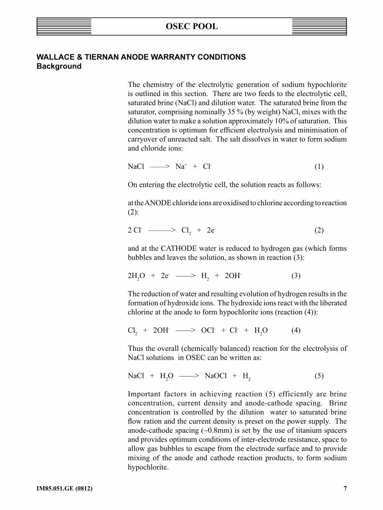
The chemistry of the electrolytic generation of sodium hypochlorite is outlined in this section. There are two feeds to the electrolytic cell, saturated brine (NaCl) and dilution water. The saturated brine from the saturator, comprising nominally 35 % (by weight) NaCl, mixes with the dilution water to make a solution approximately 10% of saturation. This concentration is optimum for efficient electrolysis and minimisation of carryover of unreacted salt. The salt dissolves in water to form sodium and chloride ions:
NaCl ——> Na+ + Cl- (1)
On entering the electrolytic cell, the solution reacts as follows:
at the ANODE chloride ions are oxidised to chlorine according to reaction (2):
2 Cl- ———> Cl2 + 2e- (2)
and at the CATHODE water is reduced to hydrogen gas (which forms bubbles and leaves the solution, as shown in reaction (3):
2H2O + 2e- ——> H2 + 2OH- (3)
The reduction of water and resulting evolution of hydrogen results in the formation of hydroxide ions. The hydroxide ions react with the liberated chlorine at the anode to form hypochlorite ions (reaction (4)):
Cl2 + 2OH- ——> OCl- + Cl- + H2O (4)
Thus the overall (chemically balanced) reaction for the electrolysis of NaCl solutions in OSEC can be written as:
NaCl + H2O ——> NaOCl + H2 (5)
Important factors in achieving reaction (5) efficiently are brine concentration, current density and anode-cathode spacing. Brine concentration is controlled by the dilution water to saturated brine flow ration and the current density is preset on the power supply. The anode-cathode spacing (~0.8mm) is set by the use of titanium spacers and provides optimum conditions of inter-electrode resistance, space to allow gas bubbles to escape from the electrode surface and to provide mixing of the anode and cathode reaction products, to form sodium hypochlorite.

IM.85.051.GE (0812)8
osEc pool
Because the efficiency of operation is critically affected by the inter-electrode gap, it is important to prevent build-up of deposits in this gap. The primary source of material which might form deposits is hardness in the feed waters. Species which contribute to water hardness (dissolved calcium and magnesium salts) tend to precipitate from solution at high pH. In the electrolytic process the generation of hydroxide at the cathode causes an increase in pH sufficient to cause precipitation of hardness deposits. This has seriously deleterious effects on electrolysis efficiency and also on the service life of the precious metal-coated anodes. For this reason it is essential that all water fed to the electrolyser has a hardness less than 17 mg/l Ca hardness. In most applications there will be a requirement that water is softened prior to entry to the salt saturator and electrolyser. Regular monitoring of the feed water hardness is a crucial part of the routine maintenance of OSEC plant.

BM.50.265 (1-494)
9IM85.051.GE (0812)
osEc pool
notES on ProtEctIVE EQuIPMEnt And cLotHInG
The following warning is general in nature due to the variety of hazardous chemicals the equipment is capable of handling.
WARNING: When dealing with hazardous material it is the responsibility of the equipment user to obtain and follow all safety precautions recommended by the material manufacturer.
It is good general practice to make use of the following types of protective clothing when handling any hazardous liquid. It is recommended that such protective equipment be used by all persons servicing this equipment and its associated piping, tubing , valves and accessories.
1 Goggles, flexible fitting, hooded ventilation (per BS EN 2092)
2 Face shield (BS EN 2092)
3 Chemical apron (BS EN 7184)
4 Chemical gloves (BS EN 7184)
5 Self contained, positive pressure breathing apparatus (BS 4667)
NoTE 1: BS EN 7028 "practice for occupational.......eye and face protection" recommends goggles (see 1 above) as the "preferred protection" when handling chemicals which present a hazard from splash, acid burns or fumes; for severe exposure, a face shield (see 2 above) over the goggles is recommended.
NoTE 2: An eye flushing fountain and a deluge type shower may also be recommended.

IM.85.051.GE (0812)10
osEc pool
tEcHnIcAL dAtA (PrIncIPLE ItEMS)
General operating data
Water pressure: 2 to 5 bar
Electrolysis current: 224 Amp. (12 kg/day) 112 Amp. (6 kg/day)
Electrolysis voltage: 10-11V (nominal)
Water flow: 1.0 l/min (12 kg/day) 0.5 l/min (6 kg/day) (Both controlled by Maric valve)
Brine flow: 0.1 l/min (12 kg/day) 0.05 l/min (6 kg/day) both manually set at control panel
Product concentration: Nominal concentration 0.8% as equivalent chlorine
Maximum inlet water temp.: 25°
skid Unit
Dimensions (mm): 1926h x 1500w x 750d
Weight: 151 kg (dry) 170 kg (working)
Incoming water connection: ½" n.b plain union connection
Product line: ½" plain union connection - solid PVC pipe
Drain line: ½" plain union connection
Vent line: ½" plain union connection - solid PVC pipe
power supply/control panel
Dimensions (mm): 500 x 600 x 300 - wall mounting
Input requirements: 230V; 1-phase, 50/60 Hz 120A unit (6kg/day) - 12A 240A unit (12kg/day) - 24A Mains connection via Type D16A circuit breaker (not supplied as standard) 6kgMains connection via Type D32A circuit breaker (not supplied as standard) 12kg
DC output: 6kg/day - 112A @ 10.5V (nominal) Cables - 50mm2 tri-rated switchgear wire
12kg/day - 224A @ 10.5V (nominal) Cables - 95mm2 tri-rated switchgear wire

BM.50.265 (1-494)
11IM85.051.GE (0812)
osEc pool
Operation: Auto/Stop/Top-up functions Alarm reset
Indicators: HMI
Alarms: General alarm contact
Water Softener—to suit site requirements
Refer to manufacturer's Instructional Manual
Salt Saturator—Integral part of skid
Air Blower AAB8232
Dimensions (mm) 212.5 L x 213.5 H x 200 Dia - side channel air blower
Weight: 5kg
Rating: 0.2 kW (110/240VAC, 1 phase, 50/60 Hz) Power derived from control panel
Noise level 52 dBA
Storage tank
200 litre
Product line: ½" plain union connection - solid pvc pipe
Hydrogen vent connection: 1½" N.B. pvc pipe - plain union connection
Storage tank level probes: Capacitive level sensor 2 levels: high level (STOP) low level (START) Optional low storage (STOP dosing pump)

IM.85.051.GE (0812)12
osEc pool
1 GEnErAL dEScrIPtIon
The OSEC Pool (On-Site Electrolytic Chlorination) is a skid unit on which is mounted all the necessary equipment for the production of sodium hypochlorite. The principle items of equipment are: the electrolyser, power supply, control panel, salt saturator (integral part of the skid), air blower, water softener, brine pump, and product tank.
1.1 Basic Equipment1.1.1 Electrolyser
The electrolyser consists of a three compartment cell, made of PVC, mounted on the skids polypropylene backboard to which softened water and saturated brine are fed. The softened (dilution) water is controlled by a solenoid valve mounted adjacent to the softener, which closes on shut-down of the electrolyser. Flow rate of dilution water is fixed by a Maric valve and flow monitored by a flow indicator (the signal from which is monitored at the control panel). Saturated brine is fed via a peristaltic pump, also mounted on the skid backboard. The cell is furnished with an electrode chassis containing anodes and cathodes connected using titanium fittings. Electrolyte level is indicated by a float operated reed switch mounted in the lid of the cell.
The anodes (positive electrodes) are rectangular titanium sheets coated with an electrocatalytic precious metal coating, consisting primarily of ruthenium oxide. This coating is selective and promotes the oxidation of chloride to chlorine. The remainder of the electrode chassis, apart from cathodes, is fabricated from titanium which is highly resistant to attack from hypochlorite and is generally resistant under oxidising conditions. The cathodes (negative electrodes) are made from rectangular sheets of Titanium, which is active towards hydrogen evolution.
The anodes and cathodes in each cell are mounted in an interleaved configuration. All anodes in each cell are connected together in parallel. Similarly, all cathodes are connected together in parallel. All cells are then connected together in series. In this way the power requirements of the electrolyser can be provided at low voltage but high current. The complete electrode chassis is mounted through the cell lid. Positive and negative terminals are indicated by labels on the lid. Electrical connection is made to the titanium posts by silver plated bolts which screw into the posts and secure the heavy duty flexible cables. The cables in turn are connected to the appropriate terminals on the rectifier and covered with a rubber insulating boot.

BM.50.265 (1-494)
13IM85.051.GE (0812)
osEc pool
The saturated brine and dilution water are fed to the inlet at the bottom of the cell. The two flows meet and mix prior to entry to the cell. When the electrolyser has filled, as detected by the float switch in the cell, the dc power to the electrolyser is switched on and electrolysis started. The electrolyte flows through the cells and is discharged from the final cell to the product tank.
1.1.2 Power Supply/control Panel
The control panel is provided in a separate, skid-mounted cabinet and is similar for both 6 and 12 kg/day capacities. The panel is equipped with all the operator controls and the associated alarms and status indicators for the electrolyser system. The system which is under control comprises the electrolyser, power supply, one air blower, brine pump and level probes (high, low and stop) in the storage tank.
The power supply is of the switched-mode type and consists of one or two modules to make up the current to suit the capacity required: 12V/120A for 6 kg/day (112A required) and 12V/240A for 12 kg/day (224A required).
The main control options are: AUTO, OFF and TOP-UP. In the OFF position only the emergency stop, hydrogen leak and low storage alarms are active. Should a low storage alarm (optional) occur, the low storage level alarm is generated and the general alarm relay is de-energised.
With the main control switch in the AUTO position, the electrolyser is started and stopped as required by the level control system. Starting when the level is below the start float switch (switch closes) and stopping when the level reaches the stop float switch (switch opens).
When the start signal is received a pre-start systems check is executed. This checks that the storage tank stop (high) level switch is closed and that the water flow switch, air flow switch, rectifier running and improper voltage contacts are open. If any of these checks fail, the appropriate alarm indicator and the rectifier running indicator are initiated. Once the pre-start check has been passed the storage tank blower is started. Once the air flow switch indicates that an air flow has been established the brine pump is started. Ten seconds later the water solenoid valve is opened and providing the cell is full (level closes float switch) the rectifier is turned on.
The system continues to run until the stop level is reached (switch opens) or an alarm forces a shutdown. At this point the rectifier is turned off and

IM.85.051.GE (0812)14
osEc pool
providing that the water flow is healthy, the brine pump and water valve are kept running for a period determined by the PLC in order to prime the cell with fresh electrolyte. The storage tank blower remains running for a minimum of 15 minutes from the time the rectifier is stopped or until the prime is complete. When selected to TOP-UP the start sequence is entered immediately, without waiting for the storage tank to drop to the start level. The fill is terminated when the stop level is reached or the selection is changed from TOP-UP to OFF. If the selection is left in the TOP-UP position after the stop level has been reached the system will not re-start when the storage tank level drops to the start level.
The dosing pump enable relay is held energised all the time the level in the storage tank is above the low storage level probe.
If the power fails while the electrolyser is running the system automatically resumes running once the power is restored.
The panel monitors and displays the following alarm conditions: ALARM DERIVED FROM Low storage level Level switch (storage tank) Low electrolyser cell level Level switch (electrolyser) Low water flow Water flow switch Rectifier not running Transformer rectifier Air flow fault/Air flow switch failure Air flow switch/overload Hydrogen leak/Emergency stop External contact
On receipt of an alarm condition, the appropriate indicator on the control panel is displayed. When the alarm reset pushbutton is pressed while an alarm light is illuminated the alarm is cleared and the system restarted. If the alarm condition is still present the alarm will be redisplayed and the system shutdown. Detailed explanations of the alarm functions are set out in Section 4.
1.1.3 Water softener
The water softener provides a softened water supply to the salt saturator to create the brine supply to the electrolyser and the dilution water supply to the electrolyser. For optimum operation of the electrolyser and maximisation of the life of the precious anodes, the hardness of the water entering the electrolyser (both dilution and brine feeds) must not exceed 17 mg/l. [This value represents the minimum hardness detectable using the Hach Model 5B Hardness Tester.]

BM.50.265 (1-494)
15IM85.051.GE (0812)
osEc pool
Because the hardness of the water feed to the electrolyser is critical to efficient operation and the lifetime of the anodes, W&T recommend that the hardness of the softened water supply is monitored weekly (as a minimum) to ensure that hardness does not exceed the recommended minimum. In order to comply with the anode warranty, W&T also require that a monthly record of operational parameters is kept by the Operator. This establishes a baseline for the operation of the system and any variance from this baseline should highlight possible degradation in performance requiring further operator or W&T service attention.
If the chlorine content of the water supply to the softener is in excess of 1 mg/l (1ppm) and no other supply exists, a carbon filter should be fitted to the supply to remove the chlorine and protect the resin. Regular cartridge replacement will be required, the frequency depending on the chlorine content of the feed water.
For full details on the water softener refer to Appendix A at the back of this manual.
1.1.4 Salt saturator
The saturated brine solution is produced by passing softened water through the salt saturator. This is an integral part of the skid containing commercial salt, suitable for manual loading (via bagged salt). The salt specification is outlined in the Anode Warranty. This specification is adequately met by pure vacuum dried (PVD) salt, which is the recommended grade of salt for OSEC systems.
The softened water enters the tank at high level via a float operated valve. Saturated brine is removed from the bottom of the tank through a ceramic filter which prevents undissolved solids passing out of the saturator tank into the brine pump suction line. As a result the water passes through the bed of salt, becoming saturated by the time it leaves the tank. The saturated brine is removed from the tank by the peristaltic brine pump fitted to the skid backboard.
1.1.5 Air Blower
WARNING: It is critical for safe operation of the electrolyser that hydrogen is removed from the tank and dispersed into a safe area.
The air blower is a safety critical component of the OSEC Pool system. As noted above, the main by-product in the electrogeneration of NaOCl is hydrogen gas. (For every kilogram of chlorine equivalent produced,

IM.85.051.GE (0812)16
osEc pool
there is ~612 litres of hydrogen produced.) Mixed with air (oxygen) this results in a potentially explosive mixture. Therefore, in addition to removing sources of ignition from the vicinity of the electrolyser, it is essential that the hydrogen is dispersed/diluted to prevent build-up of the explosive gas mixture.
The lower explosive limit (LEL) for hydrogen/air mixtures is 4% in air. To minimise the risk of explosion, the hydrogen must be diluted to less that 25% of the LEL. This achieved by blowing air into the electrolyser compartment of the product storage tank and exhausting the diluted hydrogen/air mixture to a safe zone outside the building where the OSEC installation is located. Air is blown into the electrolyser compartment which precludes the requirement for any special components operating in explosive environments. The air blower is fitted to the skid backboard beneath the control panel and ensures that “clean” air is taken into the system and blown into the electrolyser compartment and then out through the vent.
The pipe as it enters the electrolyser compartment of the skid is fitted with a airflow switch. The status of the air flow switch is monitored at the control panel and the loss of air flow results in shut down of the system. The control panel also monitors the status of the air flow switch, to check that it returns to a closed state after shut down.
WARNING: It is essential that the clear cover of the electrolyser compartment before operating the equipment. The joint must be inspected to ensure that it is completely airtight. Failure to comply with the foregoing may result in the release of a hydrogen/air mixture in excess of the lower explosive limit.
The maximum length of 75mm convoluted tube, measured from the blower to the outlet, is 40m (20m for 50mm smooth bore pipe). The following tables show how much this maximum length is reduced when elbows etc., are introduced.

BM.50.265 (1-494)
17IM85.051.GE (0812)
osEc pool
75mm convoluted Tube
Number of Reduce length by
90° Normal Elbow 1 1.0590° Short Radius Elbow 1 2.2545° Short Radius Elbow 1 1.2Tee Flow Through Branch 1 4.5Tee Flow Through Run 1 1.5Swing Check Valve 1 3.75
50mm smooth Bore pipe
Number of Reduce length by
90° Normal Elbow 1 0.790° Short Radius Elbow 1 1.545° Short Radius Elbow 1 0.8Tee Flow Through Branch 1 3Tee Flow Through Run 1 1Swing Check Valve 1 2.5
1.1.6 Hypochlorite Storage tank
The hypochlorite storage tank is fitted with two level switches (third is optional): the highest shuts down the generation process when the product reaches the maximum level; the next, lower switch (low level) starts up hypochlorite generation; the lowest level switch (“stop”) is used to inhibit the hypochlorite dosing pump, to prevent complete draining of the storage tank and suction of air into the dosing pump.

IM.85.051.GE (0812)18
osEc pool
2 InStALLAtIon2.1 Location
WARNING: The electrolytic generation of sodium hypochlorite from brine results in the production of hydrogen gas as a by-product. When mixed with air, the hydrogen presents a potential explosion hazard. To comply with Health & Safety directives the following conditions must be met when siting the OSEC Pool.
The equipment by its function creates a hazard so it must not be installed in any existing hazardous area, or have any additional equipment installed in the area after that date. The hazardous area is a ZONE 2 area which exists around the external hydrogen discharge point and above and below the discharge point. No smoking or naked flames should be permitted in or near the hazardous area. See Fig. 1 for details of zoning.
The OSEC Pool skid must be located indoors with a ambient temperature of between 5 and 40°C. Where possible the OSEC Pool should be separate from all other plant electrical items to avoid these being subject to water or chemical splashes that might occur during servicing the equipment.
2.2 Electrical connections
WARNING: MAINS VOLTAGE CAN KILL. Ensure that the supply is isolated elsewhere before making connections.
cAUTIoN: Before switching on the mains supply, check that the primary tappings on the main transformer are in accordance with those shown on the transformer/rectifier wiring diagram and suit the incoming mains supply.
The OSEC Pool electrical connections should be made in accordance with the Skid Diagram Fig.3 and External Connection Diagram Fig.4.
2.3 Water Supply
The OSEC Pool requires a supply of clean water free from turbidity. The flow rate of water into the electrolyser is controlled by a Maric valve which has an operating range of 2 (min.) to 5 bar. Where the supply pressure is in excess of this, a pressure regulating valve should be fitted into the water supply to the system.
NoTE: under the terms of the anode warranty, the electrodes should not be exposed to water/brine solution at a temperature lower than 10°C. If the temperature of the feed water/brine solution does fall below 10°C the warranty period will be reduced.

BM.50.265 (1-494)
19IM85.051.GE (0812)
osEc pool
2.4 Product line
The skid is dispatched with the hypochlorite product line disconnected at the storage tank (Fig.6 (3)), this should be reconnected.
2.5 Power Supply/control Panel
The power supply requires a 230V, single phase supply. This requires a separate circuit breaker, rated for 16A (6 kg) 32A (12 kg), type D.
The mains AC power to the power supply is switched on with a skid mounted isolator.
The control panel connects to a normal 230V mains supply via a skid mounted isolator. The connections for control and alarm contacts are shown in the table below. Further detail of the layout of connections is provided in the general layout of the control panel at Fig.6.
Contacts Terminal Block Function 1 and 2 X1 Hydrogen leak 3 and 4 X1 Emergency Stop
2.6 Storage tank
The storage tank is fitted with level probe facilities. There are two level probes: low (START) level, high (STOP) level and a optional low storage level to shut down the system and prevent air-locking of the dosing pump.
2.6.1 Level Probe connections
The level probes are connected back to the control panel. The connections are as follows:
Level indication Terminal Block Terminals High (STOP) X3 1, 2 + 3Low (START) X3 4, 5 + 6“Low-Low” (low storage) X3 7, 8 + 9
2.6.2 Air Blower/Hydrogen discharge
The skid electrolysis section is furnished with an air blower to provide a flow of air sufficient to dilute the hydrogen produced in the process to below 25% of the L.E.L. The exhaust from the electrolyser compartment

IM.85.051.GE (0812)20
osEc pool
is piped to a high level discharge point. This should be at least 3 metres from any building opening (door or window), or any source of ignition. The discharge vent should be fitted with a cowl and arranged so that the system cannot be pressurised by prevailing winds. The exhaust pipework should rise vertically from the electrolyser compartment for at least 300 mm and then be angled continuously upwards to the discharge point. This ensures that no traps, which might gather hydrogen gas, are created and that any vapour that condenses in the pipework can drain back to the tank.
The pipework should be adequately supported for its entire length and labelled as to its function and direction of flow.
2.6.3 Airflow Indication
The air flow switch for detection of air flow, is located in the blower outlet.
2.7 Softener (see Appendix A)
2.8 Salt Saturator
The incoming softened water supply enters the saturator on the side of the integral tank. The softened water supply is controlled by a float valve inside the tank. To check its operation allow the saturator to fill. Check that the float shuts off correctly and then turn off the water supply valve. Open the saturator discharge valve and release 50% of the water. The saturator can now be charged with salt to fill it to the correct level.
cAUTIoN: Care must be exercised when adding the bags of salt to ensure that damage does not occur to the brine outlet filter in the bottom of the tank.
After charging, the softened water is turned on again and the tank allowed to fill to its normal water level. Allow the system to stand to ensure full saturation. The unit is now ready for use.
The saturator will supply saturated brine to both the electrolyser and to the softener for regeneration of the ion exchange resin.
NoTE: With a new installation the brine drawn off initially will not be of the correct strength. At least 100 litres should be drawn off and the brine output checked to ensure a specific gravity of 1.2 — a measuring cylinder and hydrometer specially calibrated in % brine strength is provided as part of the optional chemical analysis kit (U85656).

BM.50.265 (1-494)
21IM85.051.GE (0812)
osEc pool
2.9 drains
The OSEC Pool skid has a drain manifold into which the softener and salt saturator overflow pipework is directed. The outlet of the drain should be directed to an appropriate waste water drain.
2.10 Hypochlorite dosing System
A pump to dose sodium hypochlorite to the point of application is required to complete the system. The control panel has contacts to shut down dosing when the level in the storage drops below the low storage level.

IM.85.051.GE (0812)22
osEc pool
3 oPErAtIon
System Parameters 6kg/day 12kg/day
Water Pressure 2 to 5 bar 2 to 5 bar
Water Flow 0.5 l/min 1.0 l/min
Brine Flow 0.05 l/min 0.1 l/min
Electrolysis Current 112 A 224 A
Electrolysis Voltage 10 - 11V 10 - 11V
Maximum Inlet Water Temperature 25°C 25°C
Prime Time 10 minutes 20 minutes
WARNING: It is essential that the clear cover of the electrolyser compartment is in place before operating the equipment. The joint must be inspected to ensure that it is completely airtight. Failure to comply with the foregoing may result in the release of a hydrogen/air mixture in excess of the lower explosive limit.
3.1 Initial Start-up
When all electrical and pipework connections have been completed, including commissioning of the water softener and salt saturator, the OSEC Pool can be brought into operation.
3.1.1 Pre-Start checks
1. Ensure that the mains water supply is open and adjust any pressure reduction valve to maintain pressure in the 2-5 bar operating range.
2. The brine pump flow rate will have been set at the factory and should not be adjusted.
3.1.2 Start-up
1. Switch on power to control panel at the skid mounted isolator. The control panel will illuminate all alarm indicators for two seconds. These should all extinguish automatically, with the exception of the low storage alarm.

BM.50.265 (1-494)
23IM85.051.GE (0812)
osEc pool
2. The digital ammeter and voltmeter should indicate ZERO in each case.
NoTE: On restart a small voltage will be indicated. This is normal.
3. Press 'AUTO' on the HMI main screen; this starts the air blower. Once a signal indicating that air flow has been established, the brine pump is started. After approximately 10 seconds the dilution water solenoid valve is opened. Once the electrolyser is filled (level closes float switch) the power supply is started.
4 Sodium hypochlorite is now being generated with the brine and dilution water in the correct ratio and is passing into the storage tank. Once the product level passes above the optional low storage level probe (if fitted) the HMI 'Reset' can be pressed to remove the alarm.
5 The sodium hypochlorite passing to the product tank can be sampled for analysis from a sample cock (not Wallace & Tiernan supply) in the product line. Care must be taken when removing sample not to remove large quantities of liquid, which may contain dissolved hydrogen. A sample volume of approximately 50 cm3 is sufficient when measuring chlorine content alone. If the specific gravity of the product is also to be determined, approximately 300 cm3 of sample will be required. (See below for analytical procedures.)
WARNING: Although in a dilute form of approximately 0.8% w/w, the sodium hypochlorite produced by the electro-chlorinator is still corrosive, to a degree, to the skin, eyes, clothing, most metals and painted surfaces. It must not be mixed, or come into contact, with any other chemical than water. Personnel handling hypochlorite should wear chemical goggles and protective clothing. Splashes in the eyes should be dealt with immediately by prolonged irrigation with running water, and medical advice should be sought as soon as possible. Similarly, splashes to the skin or clothing should immediately be washed in running water.
7 The system continues to run until the stop level is reached (switch opens) or an alarm forces a shutdown. At this point the rectifier is turned off and providing the water flow is healthy, the brine pump and water valve are kept running for a period determined by the PLC in order to prime the cell with fresh electrolyte. The storage tank blower remains running for a minimum of 15 minutes from the time the rectifier is stopped or until the prime is complete.

IM.85.051.GE (0812)24
osEc pool
3.2 normal operation
For normal operation, the OSEC Pool should be left in the “AUTO” mode. In this condition there will be automatic start of the process when the product storage level drops below the low level probe and generation cease when the level reaches the high level probe. The electricity supply to the power supply, control panel and other ancillary equipment must be maintained at all times to ensure that automatic start-up will occur as required.
3.3 System Malfunction
If a malfunction occurs in the electrolyser or associated equipment, this will be shown on the control panel HMI. The alarm can be cleared by pressing the “RESET” button and the system will restart. If the alarm condition persists, the alarm will be re-displayed and the system shut down again.
Detailed descriptions of the alarm functions can be found in Section 4.2.
3.4 Shut-down/Mains Power Failure
Whenever power is removed from the OSEC Pool through a shut down or mains failure, the unit starts in the 'OFF' mode when power is switched back on. 'AUTO' must then be manually pressed to start hypochlorite production.

BM.50.265 (1-494)
25IM85.051.GE (0812)
osEc pool
4 MAIntEnAncE
cAUTIoN: It is emphasised that when servicing the individual items of equipment which form the complete system, Wallace & Tiernan approved parts must be used for replacement purposes.
4.1 routine Maintenance
Recommendations for the routine maintenance of the peristaltic brine pump and any dosing pumps supplied with the system are found in the respective manuals. These manuals contain the necessary information on servicing, together with illustrated parts lists for spares purposes.
The maintenance required for the OSEC Pool consists mainly of good housekeeping of the system itself and the immediate location of the installation. It is important that all items of equipment are kept clean of salt, dust and splashes of sodium hypochlorite in order to minimise corrosion. The equipment should be checked regularly for leaks. The electrolyser compartment cover must be checked for airtightness.
4.1.1 Water Softener
As noted above, electrolyser operation deteriorates seriously if unsoftened water enters the process. Electrolysis of solutions of hardness greater than 17 mg/l will cause the build-up of deposits on the electrodes, with a resulting loss in efficiency and potential damage to the expensive electrocatalytic surface of the anodes. It is critical that the softener is maintained to operate at full capacity and produces a continuous supply of softened water.
Because of the critical nature of water hardness on the long-term performance of the system and the warranty of the anodes, W&T require operator to maintain a weekly log of water hardness and other operating parameters. Failure to maintain this log may void the anode warranty.
A weekly check should be made and logged on both the input supply and the output of the water softener to ensure the unit is functioning correctly. A test point should be provided in the dilution water line to enable a test sample of softened water to be obtained. To check the hardness of the water Wallace & Tiernan recommend the use of a Hach, Model 5B Water Hardness Tester which can be supplied as an optional extra with the chemical analysis kit (U85656).
If the electrolyser has been exposed to unsoftened water for any length of operation time, it is important that the electrodes are cleaned promptly to prevent possible damage by continued use. The cleaning procedure is described in Section 4.1.6.

IM.85.051.GE (0812)26
osEc pool
4.1.2 Salt Saturator
The salt saturator requires little attention other than to maintain the salt level in the tank. The incoming water supply valve should be checked periodically to ensure that the correct water level is maintained. Ensure that the strainer is fully immersed in the salt bed.
Weekly checks of the brine strength emerging from the saturator should be made using the brineometer (hydrometer) supplied with the optional analysis kit (U.85656). This is done by half-filling the measuring cylinder with brine solution from the sample tap in the line to the brine pump. Place the brineometer into the solution. A fully saturated brine should indicate 100% on the brineometer scale.
4.1.3 Hypochlorite Storage tank
There are no maintenance requirements for the storage tank other than to inspect the fittings on the tank for leakage.
4.1.4 Power Supply/control Panel
There are no routine maintenance requirements for the power supply. The unit should be kept clean and the connections be checked for security. Refer to the manufacturer’s literature or W&T for assistance.
4.1.5 Electrolyser
The anodes used in the electrolyser are warranted for 5 years from installation, unless otherwise stated at the time of ordering the system, providing the system is operated in accordance with the Warranty Conditions defined at the beginning of this manual. Claims under warranty must be accompanied by proof that the equipment has been operated correctly.
To this purpose, an Operating Log (Table 1, OSEC Operational Log) is included in the manual, which must be completed MONTHLY as a minimum, and signed by a responsible person such as a Foreman, Supervisor or Manager.
Where, because of abnormal site conditions, an acid cleaning programme is recommended, this programme must be adhered to, otherwise permanent damage may be caused to the anode coatings and the warranty voided.
Electrode cleaning
The electrode assemblies may need to be acid cleaned at extended intervals of over 1 year duration. The frequency cannot be predetermined, but can be determined from operational data (see over). The water softener

BM.50.265 (1-494)
27IM85.051.GE (0812)
osEc pool
should remove all the hardness elements, which otherwise would be deposited during electrolysis. The softener should also remove other metal ions, such as manganese. However, there may be breakdowns in the softening plant which result in the formation of deposits on the electrodes. An indication that deposits have formed is the lowering of the normal efficiency of the electrolyser by about 10%. The measurement of operating efficiency is outlined below.
The determination of efficiency is based on the concentration of equivalent chlorine in the product, as measured by titration. In order to obtain a representative analysis, the plant must be allowed to run for at least 30 minutes before taking a sample. The sample is taken from the sample tap on the outlet from the electrolyser casing.
reagents required
Potassium iodide crystals; 50% acetic acid solution (or citric acid crystals); 0.1 mol dm-3 sodium thiosulfate solution; distilled water.
Procedure
1 Place ~50 cm3 distilled water in a conical flask.
2 Add ~1 g potassium iodide crystals.
3 Add 20 cm3 acetic acid (or ~10 g citric acid crystals).
4 Using a pipette, take 5 cm3 of the OSEC product (as sampled above) and add to the flask. [This produces a deep red-brown coloration due to the iodine liberated.]
5 Titrate with the 0.1 mol dm-3 sodium thiosulfate, adding slowly until the colour is removed. As the colour is discharged, the sodium thiosulfate should be added dropwise to ensure that the end-point is determined accurately.
6 The product strength, in terms of equivalent Cl2 is calculated with
the following formula:
mg/l cl2 = T x 3.546 x 1000 Sample Vol.
where T is the titration in cm3.
[e.g. a sample of 5 cm3 is found equivalent to 11.3 cm3 of sodium thiosulfate solution; this gives an equivalent chlorine concentration of 8014 mg/l.]

IM.85.051.GE (0812)28
osEc pool
7 The concentration in mg/l can be converted to kg/hour (or day) by:
kg/hr = mg/l x total flow rate(l/min) x 60 106
kg/day = mg/l x total flow rate (l/min) x 60 x 24 106
8 Current Efficiency is calculated as follows: at 100% current efficiency 1 Amp will produce 0.00132 kg/hr equivalent Cl2 at the anodes. To determine the 100% efficiency in the electrolyser, this value must be multiplied by the current passed and the number of cells in series. In the OSEC Pool, there are 3 cells in series. So, the 100% current efficiency is:
100% CE = 0.00132 x I x 3
= 0.4435 for 6 kg/day capacity (112 Amp)
= 0.8870 for 12 kg/day capacity (224 Amp)
The current efficiency is then calculated from:
CE = 100 x measured kg/hr for 6 kg/day capacity 0.4435 = 100 x measured kg/hr for 12 kg/day capacity 0.8870
A typical figure is between 60 and 70%. However, this can vary due to the temperature and water/brine ratio.
9 Salt Usage is determined from the relationship:
kg (Salt)/ kg eq. Cl2 = 318 x brine flow l/hr 1000 x kg Cl2/hr
A typical figure is 3 - 3.5 kg salt/ kg eq. Cl2.
10 Salt Conversion Efficiency is a measure of how much salt is converted to sodium hypochlorite. Theoretically, it requires 1.6485 kg of NaCl to make 1 kg of eq. Cl2. Therefore,
Salt conversion efficiency = 100 x 1.6485 Salt Usage
A typical figure is 50% (3.3 kg/kg chlorine).

BM.50.265 (1-494)
29IM85.051.GE (0812)
osEc pool
4.1.6 Acid cleaning Procedure
WARNING: the acid cleaning requires the handling of both concentrated and dilute hydrochloric acid. Personnel should refer to the safety warnings at the beginning of this manual and manufacturer’s hazard information to be made aware of the safe handling procedures for these materials. Disposal of the hydrochloric acid used in the cleaning procedure must be carried out according to local regulations. Under no circumstances should the acid enter a drain where sodium hypochlorite may be or have been disposed, as chlorine gas will be liberated.
When a consistent decrease (~10%) in the equivalent Cl2 production rate is observed in a series of determinations (over several weeks), this is an indication that there is a build-up of deposits or other factors are negatively affecting the electrolyser. The first step to remedy this is to acid clean the electrodes. If necessary, refer to Wallace & Tiernan for advice on the acid cleaning.
The electrode chassis must be removed from the electrolyser casing for acid cleaning. Prior to carrying out any work on the electrolyser, ensure that the selector on the control panel is set to OFF and the power supply is also switched off at the mains to the control panel. Removal of the electrode chassis is then carried out as follows:
1 Slide the insulation boot off both DC power terminals on the top of the casing.
2 Unscrew both DC power connectors and remove cables; retain bolts.
3 Unscrew and remove the cell level probe from the lid of the casing. Ensure that the level probe is supported safely and will not be damaged during removal of the electrode chassis.
4 Remove all nuts and bolts securing the lid to the casing and retain. When reassembling the bolts should be tightened to 2Nm using a torque wrench.
5 The lid may now be lifted off the casing with the electrode chassis attached.
Before carrying out acid cleaning, the chassis should be rinsed with clean water to remove all traces of sodium hypochlorite (to prevent liberation of chlorine gas on contact with acid).
The chassis is most conveniently acid cleaned in a container in which the electrodes can be completely immersed in hydrochloric acid (minimum dimensions approximately 250 mm (h) x 150 mm (w) x 150 mm (d), requiring 4l of ~10% hydrochloric acid to immerse the electrodes).

IM.85.051.GE (0812)30
osEc pool
Make up the required quantity of ~10% hydrochloric acid by adding 1 part of concentrated acid to 10 parts of water and place in the cleaning vessel. Immerse the electrode chassis in the acid and agitate gently. Leave the electrodes immersed in the acid until any effervescence due to hardness deposits has subsided, with occasional agitation to ensure that fresh acid reaches the inter-electrode gap. The acid clean should be terminated after 30 minutes. At completion of the acid clean remove the electrode chassis from the acid and rinse thoroughly in clean, preferably running water to remove all traces of acid from the electrodes. If possible, carry out a final rinse with softened water.
The electrode chassis can now be replaced into the casing and the electrolyser reassembled by reversing the procedure 1-5 above. Particular care must be taken when reconnecting the DC power cables. The connections contacting surfaces must be clean and fully tightened together to prevent excessive voltage drop in the contacting areas.
NoTE: Acid cleaning may be carried out using a Wallace & Tiernan acid cleaning kit (refer to W&T for information).
4.2 ALArMS And FAuLt FIndInG
Main equipment faults will be sensed by the control panel and appropriate alarms generated.
4.2.1 Low Water Flow
Dilution water flow is sensed by the water flow switch on the incoming softened water flow which opens under conditions of low (80%) flow. The alarm is inhibited when the water solenoid valve is closed and for 30 seconds after the valve is opened. There is also a 10 second transient time to remove the effect of fluctuations in flow.
If this alarm condition is detected:
the “low water flow” alarm is generated the general alarm relay is de-energised the rectifier and brine pump are stopped the water valve closed The storage tank blower remains on for 15 minutes.
cAUsE REMEDy Failure of water supply pressure Check and remedy Incorrect pressure setting See Section 2.3 Failure of water prv Service or replace Failure of low water flow switch Replace Solenoid valve failure Replace Electrical failure Consult W&T

BM.50.265 (1-494)
31IM85.051.GE (0812)
osEc pool
4.2.2 Low Electrolyte Level
A level switch on the electrolyser cell is used to detect when the electrolyte level in the cell is correct, this opens at low level. When the system is started for the first time after being placed in AUTO, it has 10 minutes to close the switch. If the system has previously run in this auto cycle, then it has 90 seconds to confirm this level. Once the level switch has closed there is also a 5 second transient time if the switch opens before any action is taken. If the cell fails to fill or the transient time is exceeded, then:-
If this alarm condition is detected:
the “low electrolyte level” alarm is generated the general alarm relay is de-energised the rectifier and brine pump are stopped the water valve is closed
The cell level is also monitored after the electrolyser has stopped. If the level switch opens then the 'low cell level' alarm is generated. This is used as an indication rather than a latched alarm.
cAUsE REMEDy
Failure of level switch Check and/or replace Failure of water supply Check and remedy Failure of water prv Service or replace Solenoid valve failure Replace Electrical failure Consult W&T
4.2.3 Improper Voltage
This alarm is derived from a contact within the transformer rectifier, which is closed when healthy. The alarm is inhibited when the rectifier is OFF and for 120 seconds after it is switched ON.
If this alarm condition is detected:
the “improper voltage” indicator is illuminated the general alarm relay is de-energised the rectifier is stopped the brine pump and water valve remain running for the set prime period the room ventilation (if ifitted) and storage tank blower remain on for a minimum of 15 minutes
If the rectifier running contact does not close within 10 seconds of the rectifier being asked to run or opens while the system is running, then:-

IM.85.051.GE (0812)32
osEc pool
the “improper voltage” indicator is flashed the general alarm relay is de-energised the rectifier is stopped the brine pump and water valve remain running for the set prime period the room ventilation (if fitted) and storage tank blower remain on for a minimum of 15 minutes
cAUsE REMEDy Loss of brine flow or high brine flow Check Brine flow rate and reset appropriately Salt saturator water/salt levels low Recharge with salt/check ball valve Too high dilution water flow Check correct Maric valve fitted Short circuit in electrodes Consult W&T Power supply failure Consult W&T Electrolyser needs acid cleaning Acid clean as Section 4.1.6. Anodes coating worn replace anodes
4.2.4 Low Storage Level
The low storage level is derived from a flow switch in the product tank. The input to the PLC is high for level above the set level and low below the set level. The dosing pump enable relay is held energised while the level is above the set level.
If the level drops below the set level:
the “low storage level” indicator is illuminated the general alarm relay is de-energised the dosing pump enable is de-energised.
cAUsE REMEDy Electrolyser not operating Check mains supply Check controls and select AUTO Level control/probe fault Check low start level position and associated switch action Dosing pump rate too high Check and correct if required 4.2.5 Air Flow Fault
An air flow switch mounted in the storage tank blower pipework is used to monitor whether there is airflow or not, this switch is open under the no-flow condition. The alarm is inhibited when the blower is off, and for 60 seconds after the blower is started. There is also a 10 second transient time to take care of any fluctuations in the flow. The tripped contact from the blower thermal overload is also monitored.

BM.50.265 (1-494)
33IM85.051.GE (0812)
osEc pool
If this alarm condition is detected while the system is running, then:-
the “air flow fault” indicator is illuminated the general alarm relay is de-energised the rectifier is stopped the brine pump and water valve remain running for the set prime period. The storage tank blower remains on for minimum of 15 minutes.
cAUsE REMEDy Blower failure Check mains power to blower Vent blockage Clear vent Pressure switch malfunction Check and repair
4.2.6 Failure of Mains Supply
cAUTIoN: Should a failure occur in the electrical power supply to the OSEC-Pool the system will need to be restarted in the AUTO position.
4.2.7 Hydrogen Leak/Emergency Stop
External contacts for hydrogen leak and emergency stop are monitored, both should be closed when healthy. These contacts form part of a hard wired shutdown circuit to stop the room ventilation (if fitted), rectifier, brine pump and storage tank blower.
If either of these contacts open, then:-
all the alarm lights flash the general alarm relay is de-energised
If the system is running, then:-
everything is stopped
4.3 Pre-Start Systems check
When the level in the storage tank reaches the start level and providing the control switch is in the AUTO position, a systems check is performed before the electrolyser is allowed to start. This checks that certain input conditions are in the expected state. If they are not the rectifier running indicator is flashed along with an alarm light indicating the nature of the error. The electrolyser is prevented from starting.

IM.85.051.GE (0812)34
osEc pool
check Indication if incorrect (Rectifier running light flashed) Storage tank high (stop) level Low storage level alarm light flashed switch closed Water flow switch open Low water flow alarm light flashed Air flow switch open Air flow fault alarm light flashed Rectifier running contact open Improper voltage alarm light flashed Improper voltage contact open Improper voltage alarm light flashed

BM.50.265 (1-494)
35IM85.051.GE (0812)
osEc pool
TABlE 1 osEc opERATIoNAl loG
OSEC MODEL No: ..............................SITE: ........................................DATE COMMISSIONED ....................
CAPACITY: .................................kg/day
SETTINGS FOR NORMAL RUNNING: WATER FLOW RATE: ................................................. l/hr
BRINE FLOW RATE: .................................................. l/hr
AMPRERES: ...............................................................
VOLTS: ........................................................................
RECOMMENDED ACID CLEANING FREQUENCY: .......................................................................
notE: tHE tABLE BELoW MuSt BE coMPLEtEd At LEASt EVErY MontH
dAtE WAtEr FLoW l/hr
BrInE FLoW l/hr
WAtEr HArdnESS
InLEt WAtEr
tEMP °cAMPS VoLtS SIGnAturE PoSItIon

IM.85.051.GE (0812)36
osEc pool
FIG.1 ZonInG dIAGrAM (XAc1267)
ENIL F
OO
R
002 R
AERA
GNI
KO
MS
NO
NSI
UD
AR
m5
:SETO
N
EB TO
N TSU
M ENIL
RIA/NE
GO
RD
YH
ROF
EG
RA
HC
SID F
O TNI
OP
EHT .1
A SA H
CUS
GNI
NEPO
GNI
DLIU
B Y
NA
MO
RF S
ERT
EM 3
NA
HT S
SEL
ERE
HW ESI
R DL
UO
HS KR
OWEPIP T
NEV N
EG
OR
DY
H E
HT .W
OD
NIW
RO
RO
OD
EHT
MO
RF .KNAT E
GAR
OTS EHT
OT R
ES
YLO
RTC
ELE
EHT
MO
RF EL
BIS
SO
P D
NA ERTE
M 1 R
OF YLLAEDI YLL
ACIT
RE
V E
SIR
DLU
OH
S TI K
NAT
EG
AR
OTS
ON TA
HT SER
USNE SI
HT .TNI
OP EG
RA
HC
SID
EHT
OT S
DR
AW
PU
DEL
GN
A E
B N
EHT
YNA TA
HT D
NA DETAE
RC E
RA SAG
NE
GO
RD
YH
RE
HTA
G TH
GIM
HCI
HW
SP
ART
.KNAT E
HT OT K
CAB NIA
RD
NAC K
RO
WE
PIP
NI S
ES
NE
DN
OC T
AHT
RU
OP
AV
) ERTE
M/m
m51 SI ESI
R D
ETS
EG
GU
S (
HTIW
NOITA
CIFITNE
DI R
OF DE
DO
C R
UOL
OC
EB
DLU
OH
S K
RO
WE
PIP .2
DLU
OHS K
RO
WEPIP LLA .)0171 SB ( W
OLF FO
NOIT
CE
RID
GNI
WO
HS
SW
OR
RA
.HT
GNEL E
RITNE S'TI
ROF
DET
RO
PP
US
YLET
AU
QE
DA
EB
OT
SLE
BAL
GNI
NR
AW
DR
AZA
H .3RE
HW
DEH
CATTA EB.ETAI
RPO
RPPA EM
OO
R TNALP E
HT NI
DETSOP EB
OT S
NGI
S ST
HGIL
DE
KA
N R
O G
NIK
OM
S O
N .
GNI
DLIUB E
HT FO SE
RTE
M 5 NI
HTIW
OT D
NA
TENIBA
C EDI
SNI 2
EN
OZ
2 EN
OZ N
EG
OR
DY
H
002 R

BM.50.265 (1-494)
37IM85.051.GE (0812)
osEc pool
AIR
BLO
WER
WAT
ER S
OFT
ENER
1 1/
2” n
b PL
AIN
SO
LVEN
T W
ELD
HYD
RO
GEN
O
UTL
ET. T
HIS
PIP
E M
UST
RU
N S
OLI
D W
ITH
OU
TG
ASK
ETED
JO
INTS
TO
OU
TSID
E AT
MO
SPH
ERE.
REF
ER T
O F
IG.1
ZO
NIN
G D
IAG
RA
M28
5
1930
1766
1700
1500
1609
6075
0
1/2”
nb
DR
AIN
/ O
VER
FLO
W C
ON
NEC
TIO
N.
100
5750
30
710
1/2”
nb
WAT
ER IN
LET
CO
NN
ECTI
ON
PRES
SUR
E R
AN
GE:
2-5
BA
R
FIG.2 oVErALL dIMEnSIonS (XAc1266)

IM.85.051.GE (0812)38
osEc pool
23
4K3
23
4K3
230V
, 1pH
, 50H
zSU
PPLY
2.8K
VA F
OR
6K
G/D
AY3.
6KVA
FO
R 1
2 K
G/D
AY
LC O
SEC
ELE
CTR
OLY
SER
(6kg
/day
or 1
2kg/
day)
CEL
LLE
VEL
WAT
ERFL
OW
WAT
ER IN
LET
VALV
EB
RIN
EPU
MP YY
CA
BLE
2 C
OR
E &
EA
RTH
1.00
mm
2
YY C
AB
LE2
CO
RE
& E
AR
TH1.
00 m
m2
YY C
AB
LE2
CO
RE
& E
AR
TH1.
00 m
m2
OSE
C P
OO
L C
ON
TRO
L PA
NEL
DO
SIN
GSY
STEM
EN
AB
LE
GEN
ERA
LFA
ULT
VOLT
FR
EE C
ON
TAC
TSFO
R C
UST
OM
ERS
CO
NN
ECTI
ON
N/CCOMN/O
N/CCOMN/O
SUPPLYVOLTAGE
L
NE
H
YDR
OG
EN
EMER
GEN
CY
LE
AK
ST
OP
STA
RT
STO
P
CU
STO
MER
S C
ON
NEC
TIO
N
(VO
LT F
REE
)
24VDC
24VDC
BLO
WER
MO
TOR
0.12
KW
STO
RA
GE
TAN
K L
EVEL
SWIT
CH
ES(s
ee N
ote
6)
AIR
FLO
WSW
ITC
H
Q
BNBLUBLK
BNBLUBLK
BNWHT
X3:1X3:2X3:3
X3:4X3:5X3:6
IS:1IS:2
X1.1
X1.2
X1.3
X1.4
X2:1
X2:2
X2:3
K3:12K3:11K3:14
K4:12K4:11K4:14
X3:4X3:5X3:6
IS2:4IS:25
X1:5
X1:6
X2:NK1:14X2:E
X2:N
K2:14X2:E
D.C. SUPPLY
INTRINSICALLYSAFE
INTRINSICALLYSAFE
BRNWHT
REDBLU
21
G/N
21
G/N
240V AC
240V AC
NK2E
Q
NO
TES
1
INTR
INSI
CA
LLY
SAFE
CA
BLE
S TO
BE
BLU
E A
ND
RU
N S
EPA
RAT
E FR
OM
ALL
MA
INS
CA
BLE
S
2
IF H
YDR
OG
EN L
EAK
CO
NTA
CT
IS N
OT
AVA
ILA
BLE
, LIN
K T
ERM
INA
L X1
4 TO
X18
3
IF E
MER
GEN
CY
STO
P PU
SHB
UTT
ON
IS N
OT
FITT
ED, L
INK
TER
MIN
AL
X16
TO X
19]
4
TER
MIN
AL
IDEN
TIFI
CAT
ION
PR
EFIX
ED ‘K
’ DEN
OTE
S A
CO
NN
ECTI
ON
MA
DE
DIR
ECTL
Y TO
AN
INTE
RFA
CIN
G R
ELAY
IDEN
TIFI
ED B
Y TH
OSE
LET
TER
S.
5
INTR
INSI
CA
LLY
SAFE
INPU
TS C
ON
NEC
TED
DIR
ECTL
Y TO
ISO
LATI
ON
BA
RR
IER
S.
6
STA
RT
SEN
SOR
TO
BE
PRO
GR
AM
MED
N/C
WIT
H N
O L
IQU
ID IN
PIP
E
STO
P SE
NSO
R T
O B
E PR
OG
RA
MM
ED N
/O W
ITH
NO
LIQ
UID
IN P
IPE.
FIG.3 SKId dIAGrAM (XAc1277)

BM.50.265 (1-494)
39IM85.051.GE (0812)
osEc pool
NO
TES
:
1.
IF
HY
DR
OG
EN
LE
AK
DE
TEC
TIO
N IS
NO
T FI
TTE
D, L
INK
TE
RM
INA
L X
16 T
O X
19
2.
IF
EM
ER
GE
NC
Y S
TOP
PU
SH
BU
TTO
N IS
NO
T FI
TTE
D, L
INK
TE
RM
INA
L X
14 T
O X
18
3.
TH
E W
OR
DS
‘VO
LT F
RE
E’ A
PP
EA
RIN
G A
GA
INS
T A
CA
BLE
IND
ICAT
ES
TH
AT T
HE
CA
BLE
IS S
UB
JEC
T
TO
VO
LTA
GE
S A
PP
LIE
D B
Y TH
E E
XTE
RN
AL
EQ
UIP
ME
NT
AN
D N
OT
THE
CO
NTR
OL
PAN
EL
4.
TE
RM
INA
L ID
EN
TIFI
CAT
ION
PR
EFI
XE
D ‘K
’ DE
NO
TES
A C
ON
NE
CTI
ON
MA
DE
DIR
EC
TLY
TO
A
N IN
TER
FAC
ING
RE
LAY
IDE
NTI
FIE
D B
Y TH
OS
E L
ETT
ER
S.
5.
A
LL C
AB
LIN
G T
O B
E IN
STA
LLE
D IN
AC
CO
RD
AN
CE
WIT
H I.
E.E
. RE
GU
LATI
ON
S, 1
6TH
ED
ITIO
N
FO
R E
LEC
TRIC
AL
INS
TALL
ATIO
N
6.
A
LL V
OLT
FR
EE
CO
NTA
CTS
RAT
ED
- 25
0VA
C /
125V
DC
MA
X
2500
VA /
300W
7.
TH
E A
LAR
M R
ELA
YS
AR
E F
AIL
SA
FE (E
NE
RG
ISE
D W
HE
N H
EA
LTH
Y)
FUS
ED
ISO
LATO
R
CU
STO
ME
RC
ON
NE
CTI
ON
DO
SIN
GS
YS
TEM
EN
AB
LE
GE
NE
RA
LFA
ULT
230V
, 1P
h, 5
0Hz
SU
PP
LY2.
8KVA
FO
R 6
KG
/DAY
3.6K
VA F
OR
12
KG
/DAY
OS
EC
PO
OL
/ LC
PLU
S S
KID
UN
IT
VO
LT F
RE
E C
ON
TAC
TSFO
R E
XTE
RN
AL
CO
NN
EC
TIO
N
HY
DR
OG
EN
LEA
KE
ME
RG
EN
CY
STO
P
FIG.4 EXtErnAL connEctIon dIAGrAM (XAc1270)

IM.85.051.GE (0812)40
osEc pool
Key Part no. QtY description
- AAB4605 - Titanium Chassis 6kg/day OSEC Pool complete 1 AAB1586 2 Conductor post 2 AAB1551 4 Spacer 33.25 long 3 AAB4458 6 Titanium outer cathode assy 4 P121205 6 Anode 5 AAB4461 3 Titanium cathode assy 6 AAA8250 6 Screw 3/8"-16 UNC x 25 long 7 P53300 42 Spacer 8 AAA8247 6 Screw 3/8"-16 UNC x 20 long 9 AAA8244 2 Busbar screw 11 AAA8433 1 Orientation tube
Key Part no. QtY description
- AAB4608 - Titanium Chassis 12kg/day OSEC Pool complete 1 AAB1586 2 Conductor post 2 AAA8442 4 Conductor spacer 30 long 3 AAB4458 6 Titanium outer cathode assy 4 P121205 12 Anode 5 AAB4461 9 Titanium cathode assy 6 P121082 6 Screw 3/8"-16 UNC x 28.5 long 7 P53300 66 Spacer 8 AAA8250 6 Screw 3/8"-16 UNC x 25 long 9 AAA8244 2 Busbar screw 11 AAA8433 1 Orientation tube
FIG.4 ELEctroLYSEr cHASSIS

BM.50.265 (1-494)
41IM85.051.GE (0812)
osEc pool
1745 328 96 11
6
6
6
8
8
8
+
_
6
8 6 8
_
+
2 2 64
6
PART
No.
12AA
B460
8
No. O
F AN
ODES
AAB4
605
ASSE
MBLY
OF
6kg/
day C
HASS
IS
ASSE
MBLY
OF
12kg
/day
CHA
SSIS
FOR Q
UANT
ITIES
SEE S
EPAR
ATE B
ILL OF
MATE
RIAL
11
ISSU
E
APPL
Y E.
8017
8 ELE
CTRI
CAL
JOIN
TING
COM
POUN
DTO
M12
THR
EAD
BEFO
RE A
SSEM
BLY
6AA
B155
4
12AA
B155
711
TITA
NIU
MHA
STEL
LOY
CATH
ODE
TYPE
HAST
ELLO
YTI
TAN
IUM
FIG.5 ELEctroLYSEr cHASSIS

IM.85.051.GE (0812)42
osEc pool
Key Part no. QtY description 1 AAC2592 1 Enclosure drilling cp osec pool 2 AAB8301 1 PLC Mitsubishi FX1N-24MR-ES/UL 100/230 V 3 AAC2577 1 Operator interface MAC E1012 4 AAB8307 1 MITSUBISHI PLC A/D input card FX1N-2AD 5 AAB8331 1 Shunt150A, 75mV 6 AAB5452 1 Overload 1.8-2.6A 7 AAB6025 2 Contactor 24VDC 4NO 6A low consumption 8 ATI3989 4 Relay socket (P2RF-05-E) 9 AAB8646 1 Voltage converter multi I/P - O/P , 24V 10 AWO4046 4 Relay 1P C/O 24VDC 11 AAB8313 1 24V DC power supply* 12 AWO3059 17 TERMINAL 102000 13 AAA1132 2 Fuse 2amps* 14 AAA1102 4 Terminal.fused 101100 15 AAB1279 1 Switch operated relay 2 channel I/S 17 ATI3471 3 End plate 18 AAB8322 1 Power supply unit in 240V OUT 12V/125A 19 AAB8319 1 PLC FX1N to HMI cable 20 AAB8316 2 Fan 24 VDC axial 120mm x 120mm* 21 AAB8325 2 Push on fan guard for AAB8316* 22 AXQ4718 6 End bracket 038356 23 AAB8421 4 Cabinet vents 160 X 160 25 AAB8766 2 High impedance emi suppression core 27 ASG4779 5 Terminal.earth 28 5SY6110-7 1 Circuit breaker 10 AMP 1 pole 29 0914 2 Betaduct open slot 25x75 black 30 AAB8763 1 Filter 25 amp multi stage 31 AAB8574 2 Mounting bracket power supply osec pool 32 AAB8829 1 Disconnect switch 25a pole 33 W2T404160 1 Mains isolator handle 34 AAB8832 1 Shaft extension 320mm S1 type handle 35 AAB8835 1 Unswitch protective earth module 36 AAB8838 1 Terminal shrouds 3 pole 38 AAA3703 1 Cross connection 10 way 39 AAA1698 8 Nut M8 st stl 40 AAA1593 2 Scr hex M8x25 st stl 41 AWO5392 8 Washer M8 42 ASG4388 32 Washer M4 43 AAA1314 16 Scr pan M4x12 st stl 44 AAA2394 16 Nut M4 NYLOC MS 45 AAB8841 2 DIN rail angled mounting bracket 42mm H 46 AXS5842 70 Assembly rail TS35 48 AAA1734 4 Screw csk hd M4x12lg st/st 49 AAB8640 1 Busbar power supply osec pool 50 AAB8997 2 Insulating spacer GRP 40lg M8 51 AAA1599 2 Screw M8x12 hex hs st stl 53 AAA1150 2 Neutral link (044610) 54 AAA2029 2 Capacitor 55 AAB9720 5 Ferrite core 16dia 28lg* 56 W2T29013 1 12 way terminal block 32amp 60 ASG5784 100 Channel 61 6058 1 Cable gland PG13.5 grey with nut* 62 3146 7 Cable glands PG9 grey with nut 63 ASG5784 100 Channel.
FIG.6 controL PAnEL 6kg (AAc2595)

BM.50.265 (1-494)
43IM85.051.GE (0812)
osEc pool
FIG.6 controL PAnEL 6kg (AAc2595)

IM.85.051.GE (0812)44
osEc pool
Key Part no. QtY description 1 AAC2592 1 Enclosure drilling CP OSEC pool 2 AAB8301 1 PLC Mitsubishi FX1N-24MR-ES/UL 100/230 V 3 AAC2577 1 Operator interface MAC E1012 4 AAB8307 1 Mitsubishi PLC A/D input card FX1N-2AD 5 AAB8508 1 Shunt 250A, 75mV 6 AAB5452 1 Overload 1.8-2.6A 7 AAB6025 2 Contactor 24VDC 4NO 6A low consumption 8 ATI3989 4 Relay socket (P2RF-05-E) 9 AAB8646 1 Voltage converter multi I/P - O/P , 24V 10 AWO4046 4 Relay 1P C/O 24VDC 11 AAB8313 1 24V DC power supply* 12 AWO3059 17 Terminal 102000 13 AAA1132 2 Fuse 2amps* 14 AAA1102 4 Terminal fused 101100 15 AAB1279 1 Switch operated relay 2 channel I/S 17 ATI3471 3 End plate 18 AAB8322 1 Power supply unit in 240V OUT 12V/125A 19 AAB8319 1 PLC FX1N to HMI cable 20 AAB8316 2 Fan 24 VDC axial 120mm x 120mm* 21 AAB8325 2 Push on fan guard for AAB8316* 22 AXQ4718 6 End bracket 038356 23 AAB8421 4 Cabinet vents 160 X 160 25 AAB8766 2 High impedance EMI suppression core 27 ASG4779 5 Terminal.earth 28 5SY6110-7 1 Circuit breaker 10A 1 pole 29 0914 2 Betaduct open slot 25x75 black 30 AAB8763 1 Filter 25A multi stage 32 AAB8574 2 Mounting bracket power supply OSEC pool 33 AAB8874 1 Busbar power supply OSEC pool 34 AAB8829 1 Disconnect switch 25A pole 35 W2T404160 1 Mains isolator handle 36 AAB8832 1 Shaft extension 320mm S1 type handle 37 AAB8835 1 Unswitch protective earth module 38 AAB8838 1 Terminal shrouds 3 pole 40 AAA3703 1 Cross connection 10 way 43 AWO5392 8 Washer M8 44 AAB8640 1 Busbar power supply OSEC pool 45 ASG4388 32 Washer M4 46 AAA1314 16 Scr pan M4x12 st stl 47 AAA2394 16 Nut M4 NYLOC MS 48 AAB8841 2 DIN rail angled mounting bracket 42mm H 49 AXS5842 70 Assembly rail TS35 51 AAB8862 1 Mounting plate - power supply 12kg OSEC 52 AAA1734 4 Screw csk hd M4x12lg st/st 54 AAB8997 2 Insulating spacer GRP 40lg M8 55 AAA1599 2 Screw M8x12 hex hs st stl 58 AAA1150 2 Neutral link (044610) 59 AAA2029 2 Capacitor 60 AAB9720 5 Ferrite core 16dia 28lg* 61 W2T29013 1 12 way terminal block 32A 65 6058 1 Cable gland PG13.5 grey with nut* 66 3146 7 Cable glands PG9 grey with nut 67 ASG5784 100 Channel.
FIG.6 controL PAnEL 12kg (AAc2589)

BM.50.265 (1-494)
45IM85.051.GE (0812)
osEc pool
FIG.6 controL PAnEL 12kg (AAc2589)

IM.85.051.GE (0812)46
osEc pool
Key QtY Part no. description - - AAB8205 6 kg/day OSEC skid - - AAB8490 12 kg/day OSEC skid 1 1 AAB8208 Skid unit 2 5 AAA3555 ½ nb union 3 6 AAA6693 ½ nb tank connector 5 1 AAC4342 Brine pump 12 kg/day 5 1 AAC4339 Brine pump 6kg/day 6 1 AAA8781 Air flow switch 8 1 AAB8334 Electrol yser 6 kg/day 8 1 AAB8337 Electrolyser 12 kg/day 9 2 AAB6717 ½ nb ball valve FPM 10 1 AAB6699 1 nb tank connector 11 1 JU81239 Strainer 12 1 AAB8994 200 litre tank 13 5 AAA3363 ½ nb tee 14 1 AAB1171 Flow indicator 12kg/day 14 1 AAB1177 Flow indicator 6 kg/day 15 1 8064 1/2 Nb solenoid valve 16 1 AAB7734 Maric valve -6kg/day 16 1 AAB7059 Maric valve -12kg/day 17 1 AAA5002 Reducing bush 1 ½ nb x 1 nb 19 1 JP83536 Body 20 1 P100738 Nut 21 1 P89036 Collet 24 1 AAB8232 Blower 25 1 P83074 Hose adaptor 26 7 AAA3081 Pipe clip 27 7 2190 R ½ pipe nipple 28 1 AAB8226 R 1 pipe nipple 30 9 AAA3393 ½ nb elbow 31 1 AAB1299 Float valve 32 2 8181 ½ Nb banded socket plain /threaded 33 2 AAA4308 1 nb elbow 45 deg 34 1 CAB2205 1 nb pipe 35 1 AAA3408 1 ½ nb elbow 36 4 AAA4302 ½ nb elbow x 45 deg 38 1 AAB1734 Retaining bracket 39 4 AAA1146 M6 washer 40 4 ATI3486 M6 x12lg cap head screw 41 2 AAA1530 M10 x 25lg hex head screw 42 4 AAA1452 M10 washer 44 100cm RP534473 Tubing 45 1 AAB8907 Water softener 46 1 CAB2199 ½ nb rpvc pipe 49 2 AAB8187 Tubing adaptor 50 2 AAB8265 Reducing bush ½ nb x 12mm 53 1 AAB8370 Red bus bar cable - 6 kg/day 53 1 AAB8367 Red busbar cable -12 kg/day 54 1 AAB8373 Black -busbar cable - 6 kg/day 54 1 AAB8364 Black busbar cable -12 kg/day 55 1 AAB8271 Control panel 6kg/day 55 1 AAB8283 Control panel 12kg/day 56 1 AAB8343 Push fit female adaptor ½ tube x ½ bsp 58 2 AAB8346 Push fit female adaptor ½ tube x ¾ bsp (F)
Key QtY Part no. description 59 2 AAB8349 Push fit straight adaptor ½ tube x ½ bsp (M) 60 1 AAB8352 Push fit equal tee ½ tube 63 2 AAC7489 Nut M12 x 1 64 2 AAC7492 Collet 67 7 AAA1134 Screw M4 x 20lg pan head 68 2 AAB7116 M10 washer large 69 2 ATI3434 Nut M10 70 10cm CAB2211 1 ½ nb rpvc pipe 72 6 AAA2196 M10 washer spring 75 4 AAA1575 Screw M10 x 12lg hex head 76 2 AAC4324 Pump hose kit 6 kg/day only 76 2 AAD3703 Pump hose kit -12kg/day only 77 4 AHQ5469 Screw M4 x 12lg cap head 78 4 ASG4388 Washer M4 79 200cm RP9144435 PVC hose 4mm od x 1mm id 6 kg/day 80 3 AAA3114 Spacer 5mm 81 100cm RP684484 Hose 3/8 nb 82 100cm CAC4607 Water inlet tubing 85 1 AAA3561 1 nb union 86 2 AAB7797 Cable gland PG7 87 1 AAB8466 Warning label 88 1 AAB1905 Hypochlorite outlet label 89 1 L80176 Explosion label 90 1 AAA9096 OSEC nameplate label 91 1 AAB1740 Warning label 92 1 AAA9051 Instruction label 93 1 AAB7683 ATEX label 94 300cm CAC4607 Tubing 96 1 AAB8538 Valve 100 1 P88560 Reducing bush ½ nb x Rp ¼ 103 1 AAB8628 Warning label 106 2 P86332 Warning label 107 1 77367/360 Foot valve - remove strainer 108 1 AAB8973 Water softener bracket 109 2 ASG3667 Cap head screw M10 x 25lg 110 1 AAA3435 Tank connector 112 1 AAB1908 Water inlet (remove softened) 113 1 AHS4038 Label refer to instruction manual 114 1 AAA7512 Label isolate 115 1 AAB6012 Wallace & Tiernan nameplate 117 1 AAB8991 Packing kit 118 1 AAB3006 ½ nb tee 45 deg 119 1 AAC1956 R ½ nipple x 75lg 120 150cm CAC4619 ½ nb clear pvc 121 2 AAB5466 Level sensor 123 2 AAC1986 Mounting bracket for level sensor 124 1 P89696 Union adaptor 126 1 W2T405951 Stop label 127 1 W2T405952 Start label 128 1 AAB1740 Warning label cell drain valve
Important: When ordering spare parts quote the serial number of the equipment together with the full description and part number.
FIG.7 GEnErAL ArrAnGEMEnt (WAc2797)

BM.50.265 (1-494)
47IM85.051.GE (0812)
osEc pool
FIG.7 GEnErAL ArrAnGEMEnt (WAc2797)

IM.85.051.GE (0812)48
osEc pool
FIG.7 GEnErAL ArrAnGEMEnt (WAc2797)

BM.50.265 (1-494)
49IM85.051.GE (0812)
osEc pool
126
121
123
30
30 12
120
30
3
82
110
302 26
6780
30
14119
2667
80
3
6364
49
50 13
30
9613 59322667
80
1530
27
27
60
56
31
4039
3940
38
27 2 27 16 27
128
925
103
46
3630 118 89 90
30368
87
262667
80
13
30
BRIN
E CO
NN
ECTI
ON
FRO
M P
UM
P O
UTL
ET
BRIN
E CO
NN
ECTI
ON
- RU
N H
OSE
( 79
) TO
BR
INE
PUM
P IN
LET.
124
107
RUN
HO
SE F
ROM
TH
IS P
OIN
T TO
DRA
IN13
FIG.7 GEnErAL ArrAnGEMEnt (WAc2797)

osEc pool
APPEndIX A - WAtEr SoFtEnEr