Wall-Mounted Slewing Jib Crane WSK GWL - Pfaff …MA_WSKGWL_EN...Wall-Mounted Slewing Jib Crane WSK...
52
F 09.01.103_PDF_08.05.2012 / UD GB Operating and Assembly Instructions Version EN-10.2010 Wall-Mounted Slewing Jib Crane WSK GWL Slewing range 180° bis 270° (je nach Anbringung) www.pfaff-silberblau.com Prüf.- Nr. Test no. No. de vérification Type Type Type Art. Nr. Art. No. Réf. de l’article Geräte/Fabrik-Nr. Device / Serial number Numéro de série Baujahr Year of manufacture Année de construction Tragfähigkeit Capacity Capacité
-
Upload
doankhuong -
Category
Documents
-
view
232 -
download
4
Transcript of Wall-Mounted Slewing Jib Crane WSK GWL - Pfaff …MA_WSKGWL_EN...Wall-Mounted Slewing Jib Crane WSK...

F 09.01.103_PDF_08.05.2012 / UD
GB Operating and Assembly Instructions
Version EN-10.2010
Wall-Mounted Slewing Jib Crane
WSK GWL
Slewing range 180° bis 270° (je nach Anbringung)
www.pfaff-silberblau.com
Prüf.- Nr. Test no. No. de vérification
Type Type Type
Art. Nr. Art. No. Réf. de l’article
Geräte/Fabrik-Nr. Device / Serial number Numéro de série
Baujahr Year of manufacture Année de construction
Tragfähigkeit Capacity Capacité

Scope of these instructions:
The model series with designation „GWL“
wall-mounted slewing jib crane , manually swivelling with a swivelling range up to 180
degrees
From date of manufacture: 29/12/2009
The detailed scope of supply and equipment is described in the accessory purchase order documents. Characteristic technical data of the crane shall be taken from the master data list of the crane in the inspection records.
Outreach in mm Lifting capacity in kg 2000 2500 3000 3500 4000 4500 5000 5500 6000 6500 7000
50 80
125 200 250 400 500 800 1000 1600 2000 2500
Assembly I Assembly II Assembly III Assembly IV Assembly V
Drawing 1
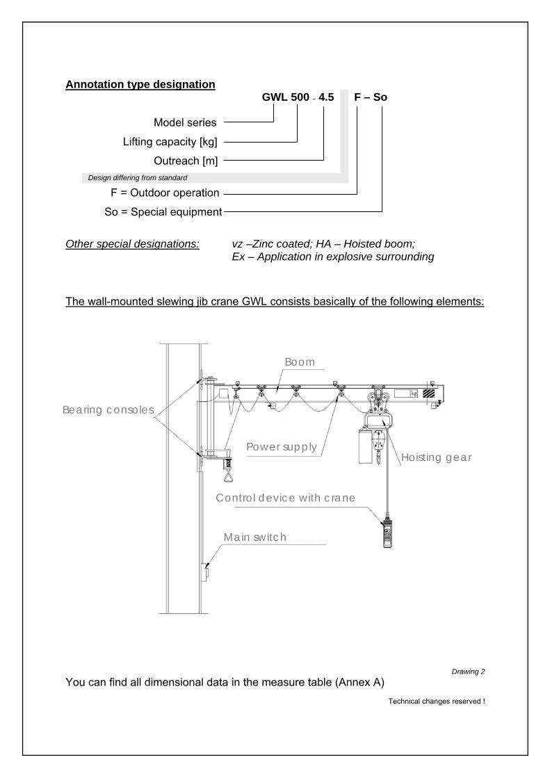
Annotation type designation
GWL 500 – 4.5 F – So
Model series
Lifting capacity [kg]
Outreach [m] Design differing from standard
F = Outdoor operation
So = Special equipment Other special designations: vz –Zinc coated; HA – Hoisted boom;
Ex – Application in explosive surrounding
The wall-mounted slewing jib crane GWL consists basically of the following elements:
Drawing 2
You can find all dimensional data in the measure table (Annex A)
Technical changes reserved !
Boom
Bearing consoles
Main switch
Control device with crane i h
Hoisting gear Power supply

Table of contents Page Introduction Part A – Operating instructions
1. Information on intended use A1
2. Usage limits A2
3. Warning of improper use A2
4. Description of dangers and warning of remaining risks A4
5. Operation of the crane A5
5.1 Control elements A5
5.1.1 Power supply switch A5
5.1.2 Control switch A5
5.1.3 Crane switch / EMERGENCY Stop A6
5.1.4 Locking device of boom A6
5.2 Operational elements A7
5.2.1 Stops for limitation of cross travel motion A7
5.2.2 Slewing brake for adjustment of the stiffness A7
5.2.3 Stops for limitation of slewing A8
6. Commissioning A9
7. Decommissioning A9
7.1 Emergency situation A10
7.2 Danger to steadiness and operating reliability A10
7.3 Closedown A10
7.4 Disposal A11
8. Non permitted use – Ban on operation A11
9. Security advices A11
9.1 Responsibility of operating company A12
9.2 Working environment A12
9.3 Choice of personnel and personnel’s qualification A13
9.4 Security advices to operating phases A13
9.4.1 Transport and Storage A13
9.4.2 Normal operation A13
9.4.3 Maintenance works A14
9.4.4 Welding works on cranes A15
9.5 Advices to special types of risks A15
10. Maintenance A16
10.1 General information A16

Table of contents Page
Part B – Assembly instructions
11. Important requirements B1
11.1 Welding works on cranes B1
11.2 General assembly advices B2
12. Overview of crane B3
12.1 Possibilities of anchorage B4
12.2 Equipment of the crane B5
12.3 Marking on crane B5
13. Assembly bearing consoles B6
13.1 Assembly of versions with positive locking B6
13.1.1 Fixation to wall B6
13.1.2 Screwed joint on flange B7
13.1.3 Bolt anchorage B8
13.2 Assembly of versions actuated by gravity B9
13.2.1 Support clasp B9
14. Assembly of the boom and the upper bearing console B10
15. Assembly of the equipment B11
15.1 Assembly of the hoisting gear B11
15.2 Assembly of the cross travel stop B12
15.3 Assembly of the slewing brake B13
15.4 Assembly of the slewing stops B13
15.5 Assembly of the locking of boom B14
16. Assembly of the electricity B15
16.1 Assembly of the basic electricity B16
16.2 Assembly of the main switch B17
16.3 Assembly of the grounding unit on boom B18
16.4 Power supply round cable B19
16.5 Power supply trailing cable B20
17. Information on adjustment B21
18. Start of operation B21
19. Safety distances to wall-mounted slewing jib crane B22
20. Additions and notes B23
Part C – Annex
A Dimension sheet B Spare parts list C Declaration of Conformity D Declaration of Incorporation

Introduction This document must be read by personnel in charge before the assembly and the initial operation as
well as before maintenance works. Provided that the complete instruction manual in not available, the
manufacturer shall be contacted. If required, the operating company shall translate the instruction
manual to user’s language. A safe operation and a long fatigue life can be only ensured with a proper
use of the crane.
This instruction manual is intended for the use of wall-mounted slewing jib cranes with booms which
can only be slewed manually.
A hoisting gear can be assembled on a crane boom solidly or with a carriage, which does not exceed,
according to data sheet, the maximum permissible values for load bearing capacity, dead weight, as
well as lifting and cross travel speed and has a rated capacity limiter. For reasons of steadiness, the
crane cannot lift from the floor, according to data sheet, more than 1.4 times the lifting capacity of the
crane. During the operation, the maximum permissible lifting load is limited to the nominal load,
according to the marked load bearing capacity. Higher loads are forbidden.
In the European Union, the legislators demand from the operators that instruction manuals shall be
always available and must be communicated to all users. In the Federal Republic of Germany it is
necessary to attach additionally a summary of the Accidents Prevention Regulations BGV D6 with the
essential security advices in a good visible manner directly on the work station of the crane operator.
Operators of crane units as well as the maintenance personnel must have knowledge of the
regulations and rules applying for this. Those are in the Federal Republic of Germany in particular:
- Accidents Prevention Regulations Cranes BGV D6
- Accidents Prevention Regulations Winches, Hoist and Traction Machines BGV D8 - BGR 500 – Load suspension device at hoisting gear operation

- A1 -
Part A – Operating instructions
1. Information on intended use
- The operator shall catch up on the intended use of the crane before start up. Improper
use is forbidden.
- The crane may be only started up, when the assembly and the equipments comply
with the valid regulations. (Declaration of Conformity is available, CE- mark is
attached, acceptance inspection or regular inspection is visible on the test seal and
still valid)
- The crane must be only assembled in an appropriate working environment. An
accident-proof operation must be ensured.
- The assembly must be executed on a floor which is permanently capable of bearing,
plane, vibration- and oscillation-free.
- In the Federal Republic of Germany, only persons who meet the requirements
according to UVV (accident prevention regulations) BGV D6 §29 can be appointed as
crane operators.
- The application and the use of the crane are permitted according to classification in
hoisting class and loading group according DIN 15018 (see information in test book).
- The wall-mounted slewing jib crane is intended to lift and drive (in each case power-
operated or manually) loads on the boom using a hoisting gear. The slewing of the
boom may be only executed manually, whereby the load must be guided by another
person.
- Only hoisting gears which have a dead weight that does not exceed the limiting value,
according to dimensions table [Annex A], may be used on the lifting arm to lift and
drive loads.*
- The maximum permissible lifting speed of hoisting gears on the crane is 8.0 m/min. *
- The maximum permissible driving speed of power-operated trolley gears is
20.0 m/min*
- Only hoisting gears with an effective rated capacity limiter (e.g. safety clutch) may be
used.
- The wall-mounted slewing jib crane is designed for a temperature range between –
10°C and +40°C.
- Only wall-mounted slewing jib cranes with additional mark “F” in their type designation
are designed for an outside operation and can be operated till wind force 4, provided
that the operating instructions are observed.
- Only wall-mounted slewing jib cranes with the additional mark “ex” in their type
designation are designed for the operation in potentially explosive areas and can be
used in the respective area according to their marking on the device and in the test
book.
- Under operating conditions above the corrosion-protection class C2 or in the
environment of aggressive mediums, special models are required. *) If higher values are permitted, thanks to special designs, they are recorded by the manufacturer in the additional data sheet. The additional data sheet is a component of the test book.

2. Usage limits The use of slewing cranes is limited by the number of load alternations (frequency), the load spectrum
(load distribution) as well as by the design (execution) of the crane. The use of the crane outside of
the intended range can result in dangers to and damages on the crane.
Characteristic usage limits are:
- Higher dynamic load:
Use of hoisting gears and load suspension devices, which require a higher classification
into loading group and hoisting class, according to DIN 15018, as designated in the test
book of the crane, e.g. during grab or magnet operation.
- Tendency to fractures of brittle materials, e.g. glass panels
The boom bounces because of the elastic deflection. A gentle set-down is, according to
the self-supporting length (column + boom), only possible to a limited extend.
- Operation at temperatures under -10°C and over +40°C
- Use under extreme ambience conditions, e.g. smelting furnaces, acid baths and areas
with strong vibrations.
- Actions which influence the static of the crane and its stability, e.g. extensions or
shortenings of the boom or the column, modifications of attachments, modification of the
load bearing capacity, subsequent installation of a hoisting gear, bigger or heavier as
intended or unapproved welding works.
3. Warning of improper use
The following use of the crane is forbidden. A nonobservance can result in risks for the operator and its environment as well as damages on the crane structure.
- The use of a crane which is assembled improperly or an equipped crane without
manufacturer’s certifications (Declaration of Conformity, CE mark) or test badge.
- The fixation/anchorage on insufficiently stable construction (wall/hall column or
similar)
- The use of a crane which is clearly damaged or defective, maybe also ignoring
the blocking and prohibition signs.
- Transport of unpermitted loads, such as passenger transportation, transport of
fused materials, transport of loads which are heavier than the permitted load
bearing capacity of the crane
- Stay under suspended loads
- Diagonal pulling, trailing or sliding of loads
- Release of uncontrolled movements of the boom or the hoisting gear by fixing the
load not perpendicular under the hook
- Inching operation of the hoisting gear – then, swing up of the boom by operation
of the hoisting gear or interventions on the suspended load
- A2 -

- Lost of fixed loads, lifting of covers (e.g. of recipients under residual vacuum)
- Slewing of the boom by pulling the control switch
- Welding works on suspended loads
- Lifted loads – must not be exceeded by additional load, must be set-down during a
stoppage of the transport process, must not rest in the suspended position if they are
unattended, must not tilt or knock over into the load cable because of a movement of
the center of gravity.
- During a use on the open air ground only such loads (dead weight, geometry, surface)
may be used, which may be reasonably controlled by the user with the available
means under the respective wind forces.
- Hooking of the crane hook in loads of fixed points and “tightening” of the load-carrier
for the protection against unintentional movements.
- Unpermissible high operating heights or operating distances – the crane operator
must be able to operate the manual operated crane in every position in a save
manner and to slow the load down.
- Uncontrolled drive to final positions with a high manual speed
- Improper anchoring or fastening of the crane, in particular with anchor bolts in the
bottom flange holes on the column tube
- Additions not intended or authorised by the manufacturer or design modifications on
the crane
- Fitting or mounting to air, water or landcrafts or other moveable machines not
intended or authorised by the manufacturer. (also cranes)
The wall-mounted slewing jib crane is not designed for continuous operation (continuous load changes in automatic processes).
- A3 -

4. Description of dangers and warning of remaining risks List of dangers according to EN 14121-1 for slewing cranes
N°
Danger potentials Danger Solution / Warning
1 Mechanical dangers of operator / of third persons by the load Observe safety distances ,
Observe swing of the load and braking distances of operator by the boom Observe safety distances
Attach stops of operator by boundaries on the final positions (arrestors)
Observe safety distances Observe operating instructions Mark danger areas
1.1 Crushing
of operator / foot by the load Observe safety distances, Observe swing of the load, Keep passing places free
1.2 Shearing of operator / hand by the boom, column, wall, support
Observe safety distances Observe operation instructions Mark danger areas
of user by swing of the load Observe safety distances of operator / third persons by the boom Observe safety distances,
Warnings on the boom
1.3 Impact
of operator / third persons by unexpected / unintended start
Use additional attachments (slewing brake, adjustment device of boom) Observe safety distances Observe operation instructions
of operator / third persons by the load Observe safety distances 1.4 Fall down of pieces of operator by unintended operation Observe safety distance,
Observe operating instructions 1.5 Stability of operator by underground floor / wall / slab Leave danger area,
If possible, lower the load immediately,
Stop the crane,
Only dispose the load on sufficiently sustainable underground 1.6 Stumble and falling of operator / third persons Keep operation ways free, safeguard tripping points if necessary
Ensure sufficient stability, Warnings in the working area
2. Electric dangers 2.1 Electric shock of operator by a damaged coating of electric
conductors Stop operation, Switch power off, Replace defective lines
2.2 Error on power supply, functional disorder of the control system
of operator / third persons Activate emergency stop and Start measures for fault clearance by a qualified person
4. Noise dangers 4.1 Discomfort, stress, failure of the voice
communication of operator / third persons by warn parts or grinding surfaces
Stop operation, Fix the error
7. Material / substance dangers
7.1 Operating supply items (oils, greases, lubricants)
of operator /third persons / environment by the hoisting gear
See special operating instructions manual for hoisting gears and drives
7.2 Fire and explosion of operator / third persons by electrical operated crane
Use only cranes designed for outside areas Observe device categories and zone classification according to the document on explosion protection of the operating company
8. Ergonomic dangers 8.1 Inadequate local illumination of operator / third persons Ensure adequate illumination
8.2 Human error of operator Training 9. Dangers by operational environment
9.1 Lightning of operator / load Stop operation immediately, Lower the load immediately, Stop the crane
9.2 Wind of operator / third persons by an uncontrolled drift of the load
Stop operation immediately, If possible, lower the load immediately, Stop the crane
9.3 Frost of operator by unexpected crane movements and starts
Observe temperature range
9.4 Exterior effect of operator by e.g. other means of transportation Observe crane, load and environment attentively
10. Combination of dangers
10.1 Failure or incorrect arrangement of protective measures
of operator Take measures to reduce the danger potential
10.2 Start and stopping device of operator by control switch Push emergency stop in the case of a defective control switch, switch the machine neutral, replace parts
10.3
Security symbols / signals Information and warning devices
of operator by faulty labelling Hold labelling readable
10.4 Turn-off devices of power supply of operator by power supply switch and emergency stop
Check on functioning before starting the work
10.5 Emergency measures working area / operating company Push emergency stop, if the danger can be reduced with this action
10.7 Failure assembly of operator Stop operation, fix the errors
Table 1
- A4 -
5. Operation of the crane / operation modes / intervention processes of the operating person
Basis for the operation of the crane are the operating manuals for crane and hoisting gear as well as
the UVV cranes (BGV D6). These documents shall be displayed on place by the operating company of
the machine. These instructions, advices and directives shall be observed.
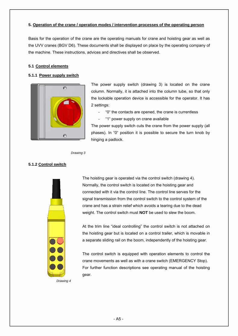
5.1 Control elements 5.1.1 Power supply switch
The power supply switch (drawing 3) is located on the crane
column. Normally, it is attached into the column tube, so that only
the lockable operation device is accessible for the operator. It has
2 settings:
- “0“ the contacts are opened, the crane is currentless
- “1“ power supply on crane available
The power supply switch cuts the crane from the power supply (all
phases). In “0“ position it is possible to secure the turn knob by
hinging a padlock.
Drawing 3
5.1.2 Control switch
The hoisting gear is operated via the control switch (drawing 4).
Normally, the control switch is located on the hoisting gear and
connected with it via the control line. The control line serves for the
signal transmission from the control switch to the control system of the
crane and has a strain relief which avoids a tearing due to the dead
weight. The control switch must NOT be used to slew the boom.
At the trim line “ideal controlling” the control switch is not attached on
the hoisting gear but is located on a control trailer, which is movable in
a separate sliding rail on the boom, independently of the hoisting gear.
The control switch is equipped with operation elements to control the
crane movements as well as with a crane switch (EMERGENCY Stop).
For further function descriptions see operating manual of the hoisting
gear.
- A5 -
Drawing 4

5.1.3 Crane switch / EMERGENCY Stop
The red marked crane switch (EMERGENCY Stop) (Drawing 5) stops with
operation (pushing) all power-driven functions. By a short clockwise turning the
red switch goes back to its starting position and all functions are operational
again.
Please refer to the operating manual of the hoisting gear manufacturer. Drawing 5 (Example)
Never operate the EMERGENCY Stop together with other operation element – this could result in movements of the crane.
5.1.4 Locking device of the boom (special equipment, serial at operation in open-air ground)
The locking device of the boom (drawing 6) serves for the secure fixing of the boom in one or more
fixed positions of the slewing range. At cranes which are designed for the use on open-air ground, the
locking device of the boom serves for the wind bracing on one boom position minimum. The operation
(Loosening / Locking) is allowed till approx. wind force 4. Beyond that, very high operating forces
occur and the drifting boom is potential danger. For this reason, only loose the locking device if there
is no danger of drifting booms due to wind.
The operation takes place by pulling the
operating rod (A1) till the return stop (A2)
below the bearing plate is visible and the
locking bolt (A3) releases the boom (1). Now
the run-back of the locking pin (A3) is
avoided by a 90 degree turning of the
operating rod (A1). The boom can slew
freely. If the boom shall be locked, it shall be
slewed manually to a locking position till the
locking bolt (A3) is located under a drilling /
locking strap (A5). The locking of the bolt
takes place in reverse order.
Drawing 6
- A6 -

5.2 Operational elements All stops are designed as EMERGENCY end stop and must not be arrived during normal operation.
(see also BGV D6 § 30).
5.2.1 Stops for limitation of cross travel motions The pictured stops of cross travels are exemplary and can differ according to hoisting gear make.
Drawing 7
5.2.2 Slewing brake for adjustment of the stiffness
Drawing 8 As special equipment, the slewing brake (drawing 8) serves for the adjustment of the stiffness of the
boom (see mounting instructions paragraph 15.3). Slewing brakes are intended for cranes in closed
halls.
- A7 -
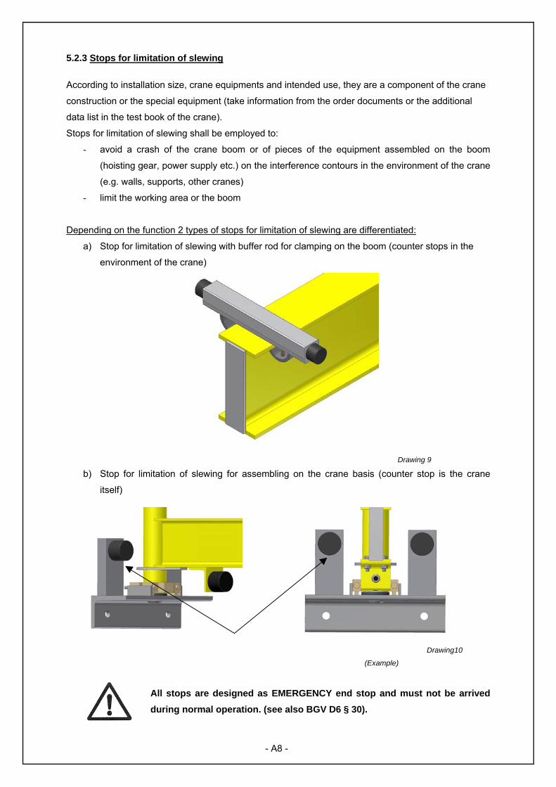
5.2.3 Stops for limitation of slewing
According to installation size, crane equipments and intended use, they are a component of the crane
construction or the special equipment (take information from the order documents or the additional
data list in the test book of the crane).
Stops for limitation of slewing shall be employed to:
- avoid a crash of the crane boom or of pieces of the equipment assembled on the boom
(hoisting gear, power supply etc.) on the interference contours in the environment of the crane
(e.g. walls, supports, other cranes)
- limit the working area or the boom
Depending on the function 2 types of stops for limitation of slewing are differentiated:
a) Stop for limitation of slewing with buffer rod for clamping on the boom (counter stops in the
environment of the crane)
Drawing 9
b) Stop for limitation of slewing for assembling on the crane basis (counter stop is the crane
itself)
Drawing10
(Example)
All stops are designed as EMERGENCY end stop and must not be arrived during normal operation. (see also BGV D6 § 30).
- A8 -

6. Commissioning
- the statutory acceptance tests (according to UVV BGV D6 § 25) must have taken place before
the initial operation
- the crane must be evidently in a safe and functional condition
- the operator must have read and understood the operating manual
Steps before commissioning
- visual inspection that all parts are free of external damages and reliably operating
- activate the power supply switch on the crane column
- unlock the EMERGENCY Stop button on the control panel
- loosen the locking (if existing on the crane)
- use boom and hoisting gear
Transport of loads
- Select adequate slinging means for the chosen load and the transport.
- Hinge the load hook and the boom above the load centre into the load or the slinging mean
and tighten the load cable carefully.
- Always lifting the load from the floor in fine motion. Use a faster lifting speed for the lifting to
the desired height not before the load is hanging safely.
- At manually operated cranes, all moves shall be realised by guiding the load or the load cable.
The crane operator must drive manually and partially power operated cranes so, that he is
able to stop the released travels and rotations without any danger.
EMERGENCY Stops (stops) must not be arrived non-braked.
- If a direct guiding of the load is impossible, additional guiding aids (e.g. ropes, chains or
guiding rods) shall be attached on the load, the load hook or the boom.
- Keep the transport process shortly and put the load in a safe position and completely down.
Hang the load hook out and bring it to a safe stand-by position.
7. Decommissioning The crane shall be stopped at the end of work or longer stoppages of work as well as in cases of
recognized damages or occurring critical situations.
- Hoisting gear in standby position
- Push power supply switch to 0 condition
In cases of interruptions, shutdown or wind force >4, the booms of cranes in operation on open air
ground shall be locked by a serial locking in its standby position.
- A9 -

7.1 Emergency situation
An emergency situation exists, if the crane movement does not stop or is impeded, e.g. by jamming or
catching loads.
Acting in case of emergency situations - Activate the existing EMERGENCY – STOP devices on the control switch or the
power supply switch!
- Inform immediately the competent authorities of the company!
- Safeguard the danger area!
7.2 Danger to steadiness and security of operation The steadiness is not ensured:
- if there are cracks on welding seams of the crane column or the boom,
- if there are loosen attachments or screw joints,
- if buildings – floor, wall, slab, supports, frames cannot absorb the fet forces anymore
The security of operation is not ensured:
- in case of a high wear of components; breakage, cracks, deformation, corrosion of load
bearing components on the crane or in load bearing means (ropes, chains, hooks),
- in case of a damage on electrical equipment, - if loads cannot be hold (rated capacity limiter and/or brakes faulty or worn) - if there are damaged functional components (stops for limitation of cross travel motion,
slewing limitation stops, etc.), - in case of a overload of the crane by exceeding the permissible lifting capacity or e.g. by
inching the control switch frequently during the lifting or lowering movement, which results in a
higher dynamic pressure. (“inching operation is forbidden!“)
7.3 Closedown
A closedown of the crane shall be carried out in case of:
- damages or wear till the repair is carried out
- achievement of the theoretic remaining service life,
- absence of the required maintenance and quality inspections (see inspection plate on crane)
After the closedown another use of the crane must be excluded, e.g. by locking the power supply
switch in “Off” condition with a padlock.
7.4. Entsorgung - A10 -

7.4. Entsorgung After the end of the operation period or irreparable damages on the crane the same must be shut
down and disposed as steel scrap. The disassembly shall be only executed by a competent person
and in reversed order to the assembly. Electric components on the crane shall be disposed
environmentally friendly.
8. Non permitted use – Ban on operation
No Transportation of persons!
No Transport of fused materials!
No Diagonal pulling, trailing and loose of stucked loads!
No Slewing of loads or moving of the crab by pulling the control switch!
No Stay in danger area during the crane operation!
No Stay under suspended loads!
No Use of damaged load bearing mediums and load handling devices!
No Transport of unsecured loads!
No Loads which exceed the indicated load bearing capacity and the classification!
No Unintentional crane movements due to faulty operation, insufficient braking
efficiency!
No Load lifting by inching operation or swinging up of the boom as a result of
external influences!
No Rest of the loads in suspended positions without control!
No Welding works on suspended loads!
No Fixing of hoisting gear or boom by insertion of the hook and “lifting opened” so
that the system is permanently loaded
Please note: Note on paragraph 3. Warning of improper use
9. Security advices
The wall-mounted slewing jib crane is designed and constructed according to the state of technology /
the valid safety requirements*. It meets the demands of the EC Machinery Directive. Using the crane
as intended the dangers to life and limb of the operator and third persons as well as of the material
values are low. Thereby a sensible handling with regard to security and dangers according to the
operating manual of the crane and the hoisting gear is assumed.
The crane must be stopped immediately if defects or irregularities are determined at the function. The
safety distances shall be observed obligatory according to the valid directives BGV D6 §11. *) At the date of placing on the market
- A11 -

9.1 Responsibility of the operating company
- Right selection and load of the crane
- Sure function and fixation on crane and loads
- Sure operating condition of the crane
- Sure operation and use by the operating personnel
- Initiate required acceptance tests and recurring inspections
You, as operating company, are responsible for the acceptance of the crane and for recurring
inspections (maintenance) according to BGV D6 and BGV D8.
All persons who are authorised with the operation and maintenance of this crane must have read
carefully and understood this operation manual. Any non-compliance and act in opposition can result
in accidents and dangers.
Additional to the operation manual, the operating company of crane units must also observe and
instruct the general laws and provisions for the prevention of accidents and to the environmental
protection.
The following protection devices exist on the wall-mounted slewing jib crane:
1. Stops for limitation of cross travel motion on boom (emergency stop device)
2. Slewing limitation stop (partial special equipment)
3. Protective conductor of boom and crane column (only cranes with electric equipment)
Due to special local conditions or cases of operations, situations could exist or appear, which are not
considered in this operating manual. In such cases the required measures for the security of the
operator shall be decided and initiated.
The operating manual shall be completed by the operating company with instructions regarding work
organisation, working processes, authorised personnel, obligations of supervision and to inform etc.
9.2 Working environments
The wall-mounted slewing jib cranes are remote-controlled cranes. That results, that the operator must
know the working environment, especially with regard to obstacles in working and transport area,
possible tripping points and existing control elements and safety devices (e.g. emergency stop switch).
Release and swing of loads are forbidden. Manual operated cranes shall be guided on the load hook
and/or the load. Safety distances to stacked material must be observed. The guiding of loads on
ramps, chambers or towers is dangerous. There is a risk of falling. Here, the operating company
arranges additional safety measures.
- A12 -

9.3 Choice of personnel and personnels qualification
According to UVV BGV D6 § 29 the following directive applies:
“To operate and maintain the crane independently the operating company may only authorise
persons,
- who are physically and mentally suitable
- who are likely to fullfill their tasks reliable
- who are instructed in driving and maintain the crane and have demonstanted their
competence
- who have reached 18 years of age.
Only adequate qualified personnel may be deployed for repairs and maintenance works.
Works on electric equipment may only be executed by an authorised electrician or by instructed
personnel and under the direction and supervision of an authorised electrician.”
9.4 Security advices for operating phases 9.4.1 Transport and storage The wall-mounted slewing jib cranes must be transported and stored as demounted components.
Hereby the boom is not stable due to its geometry. For this purpose the components are provided ex
works with adequate disposable transport aids (pallets, square timbers, stretch tapes). This transport
aids shall not be removed before the assembly. During the transport, the packing units shall be
secured on the transport mean against slipping and tilting (e.g. load restraint assemblies in case of
delivery with truck).
In case of a later assembly of the crane the components crane column and boom shall be put for
transport and storage on adequate stable transport aids and shall be additionally secured against
tilting, rolling and slipping with load restraint assemblies and support blocks.
The components shall be stored so, that they are protected against climatic influences. The storage
can take place between –20°C and +45°C.
9.4.2 Normal operation Emissions Noise emission: At motor driven hoisting gears the noise emissions vary from low up to high noise
levels. Please read the information in manufacturer’s operating manual of hoisting gear for advices on
emissions of hoisting gears. Other emissions are not known till this day.
- A13 -

Observe the following security advices during the daily operation:
- Only work with a safe and functional crane. All EMERGENCY Stop devices and control
elements must be available and meet the requirements.
- Only work with the crane if you know the limits of the machine (load bearing capacity,
allowd speeds, working areas) and you are familiar with the operation. (function of control
elements and safety devices)
- Refrain from actions which endanger the stability of the crane.
- Ensure a safe working environment and refrain from risky actions.
- Check the crane minimum once per shift for externally visible defects and faults.
- Stop the crane in case of visible faults or abruptly changed operating performance (see
operating manual chapter 7) and act according to operating manual point 9.4.3.
9.4.3 Maintenance works Observe the following security advices during works on the crane:
- The maintenance means measures for maintenance, inspection and repairs. These works
may only be executed by qualified personnel.
- The adjustment and maintenance works as well as inspection intervals, including
information on replacement of components, specified in this operating manual, shall be
observed.
- The crane unit shall be stopped during all works and secured against unintentional or
unauthorised start. (lock power supply switch with padlock and/or attach warning plate on
the switch) If necessary, the working area shall be protected.
- Ensure that the electric components and cables are dead-voltage before working on
electrical installations and facilities of the crane unit.
- During the assembly, single parts and bigger components must be safety attached with
adequate hoisting gears. Do not stay under suspended loads.
- During assembly works over 1.80 m an adequate access method (ladders, work
scaffoldings, platforms for lifting persons) shall be used and a fall protection shall be worn.
Do not use parts of the crane as climbing aids.
- If a temporarly disassembly of safety devices is necessary, they shall be reattached
before commissioning.
- Check all screw fittings on the crane for tight hold during maintenance works.
- After finishing all works on the gear the operating company may release the gear not
before inspection to proper condition. If necessary, a competent person or authorised
expert shall be commissioned with it.
- A14 -

9.4.4 Welding works on cranes
You may only weld on cranes if:
- it is required and described in the assembly instructions
- the manufacturer has authorised this welding works
- all requirements for the welding are complied with.
Requirements for welding works on cranes:
- obtain a written approval of the operating company (hot-work permit)
- observe UVV BGV D1 " welding, cutting and allied processes "
- observe VDI – Directive 2382 / 1990 – 08 " Maintenance of crane units; welding, stitching,
flame cutting, drilling"
- qualification of manufacturer class E according to DIN 18800-7:2002 (steel structures)
required
- valid welder’s performance qualification according to DIN EN 287-1 of the working welder
required
9.5 Advices to special types of risks Dangers by crushing hazard at the wall-mounted slewing jib crane
During operation:
- by swinging or falling loads
- by a run over of indoor cranes
- by moving crane parts during the arrangement of parts of the construction in
working and transportation area
During maintenance:
- by unlocked, slewing booms
- by unsufficient stability of the crane
Dangers by electric power (electric shock)
- faulty electric connections
- Parts of the construction which are energised because of defect coating
- unsufficient distance to aerial cables or open current bars of indoor cranes
- during maintenance works on energised parts
Dangers due to the hoisting gear
- due to unintended movements due to errors or defects on the electric installation or
controller (e.g. independently running motor movements or incorrect rotating
direction of drives)
- A15 -

10. Maintenance Maintenance works on the wall-mounted slewing jib crane serve for the maintenance of the operating
reliability and the functionality and increase the fatigue life of the machine. The maintenance must be
carried out regulary and by experienced qualified companies and/or qualified persons according to
BGV D8 §23 and BGV D6 §26.
10.1 General information Even though the crane is extensively maintenance free, the components which are subject to a wear
must be checked regulary.
With an intended assembly and use of the crane, the service life of any wear parts amounts normally
to 10 years. In case of a stress above average as a result of external influences the service life can be
shortened, so that the wear parts must be replaced early.
Components which are essential for a sure operation must be checked per working
day and before every use.
Inspection interval: The inspection intervals are fixed on 12 months for all parts according to the
design of the crane for the entire service life.
The following components must be checked regulary:
Daily inspection / before commissioning – X
Inspection every 12 months – O
Components Pos. N° Check for Measures
Wear parts: Buffer stops for cross travel motions 110 Functionality / wear
Replace the buffers, If necessary, correct fitting and fixation
X
Stop buffer for slewing stops 41.10 Functionality / wear
Replace the buffers, If necessary, correct fitting and fixation
O
Slide ring 21 Wear Replace slide ring O Slewing brake 40 Wear of the brake pad,
Pretension of the disc springs Replace the brake pads Replace the disc springs O
DU bushes 100 Too much clearance Replace the DU bushes O Locking of boom Breaking of the spring,
Wear of the locking pins Replace spring Replace locking pins X
Electrical components: State of cables and electric lines Correct operation and coating Stop the crane and repair defective installation by
a qualified electrician O State of main switch
Correct operation and locking capability
Stop the crane and repair by a qualified electrician X
- A16 -
Components Pos.-N° Check for Measures
Other components: Marking of load bearing capacity
Correct marking of load bearing capacity on crane and hoisting gear
Attach right marking X Check of corrosion protection Defects Refit corrosion protection O
Screw joints / Attachments Tight fitting and existing locking devices / Tightening torque
Tighten the screw joints with dynamometric key, add locking devices O
Weld seams Cracks (especially foot flange) Stop the crane and inform qualified personnel for repair O
Protection against slipping (at support clasp) Tight fitting Stop the crane and inform qualified personnel for
repair X Table 2
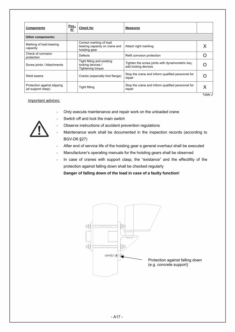
Important advices:
- Only execute maintenance and repair work on the unloaded crane
- Switch off and lock the main switch
- Observe instructions of accident prevention regulations
- Maintenance work shall be documented in the inspection records (according to
BGV-D6 §27)
- After end of service life of the hoisting gear a general overhaul shall be executed
- Manufacturer’s operating manuals for the hoisting gears shall be observed
- In case of cranes with support clasp, the “existance” and the effectifity of the
protection against falling down shall be checked regularly
Danger of falling down of the load in case of a faulty function!
- A17 -
Protection against falling down (e.g. concrete support)

Part B – Assembly Instructions
11. Important requirements These assembly instructions apply to the installation of a wall-mounted slewing jib crane.
Please read the operating manual before starting the assembly. The drawings stated
in the manual are exemplary and may differ from the model provided.
The following safety instructions shall be observed during a proper assembly:
For assembly personnel
- The assembly work must be executed by qualified personnel only and shall be
coordinated between the operator and the operating company.
- The assembly personnel shall be protected against local dangers during the assembly
of the crane.
- Wear protective equipment!
- Auxiliary material shall be used in a manner that danger to person due to unintended
use will be prevented.
- Only adequate and certified tools shall be used during the assembly of the wall-
mounted slewing jib crane.
- The work steps described below shall be observed.
- The stay under suspended loads is forbidden.
- The unit shall be activated considering the electrotechnical instructions and only
assembled in zero potential condition.
For assembly site
- The working and danger area shall be sufficiently secured.
- Customer specific instructions shall be observed
- Hoisting gears and auxiliary material, adequate for the assembly, must be available,
certified and in proper state and shall be used according to the intended use.
11.1 Welding works on cranes
You only may weld on cranes if:
- It is required and described in the assembly instructions
- We, as manufacturer, have allowed the welding works
- All requirements are complied with (see 9.4.4)
- B1 -

11.2 General assembly advices
- Wall-mounted slewing cranes only operate correctly if they are assembled according
to this manual.
- Statutory tests and maintenances must be executed at regular intervals.
- Before every assembly, the installation conditions on site and the crane and
installation height due to the design shall be checked. The statutory safety distances
shall be observed.
- Only wall-mounted slewing jib cranes with additional mark “F” in their type designation
are designed for an outside operation and shall be assembled and operated there.
- Only wall-mounted slewing jib cranes with the additional mark “ex” in their type
designation are designed for the operation in potentially explosive areas.
- For the included hoisting gears, the respective operating manuals of the manufacturer
shall be observed.
- After finishing the assembly, execute all crane functions carefully and check the
proper function.
- Operating instructions shall be attached on the crane in a clearly legible manner.
- At power operated cranes and all cranes with a load bearing capacity higher than
1000 kg, checks must be executed according to UVV- Cranes BGV D6 §25 before
initial operation.
- All checks shall be executed according to §19 of IEC 60204-32.
- B2 -

12. Overview of crane
Constructional design
Power supply
Round cable
Trailing cable
Ideal control system
Variants of the bearing consoles
Assembly I-III
Assembly IV -V Table 3
- B3 -
Bearing
Boom Power supply
Cross travel
Hoisting
Slewing brake
Boom locking
Main switch Control switch

12.1 Possibilities of anchorage
a) Fixation to wall b) Screwed joint on flange
c) Bolt anchorage d) Support clasp
Table 4 Requirements on the wall: - Minimum concrete quality B25 or C25/30
- Free of vibration an oscillation
- The joint and supporting surfaces must be even and vertical - The load bearing capacity must be ensured
Requirements on the support: - Free of vibration an oscillation
- The joint and supporting surfaces must be even and vertical - The load bearing capacity must be ensured - Open profiles (such as I profiles) are flexible in torsion and so they must be sufficiently
dimensioned and require, if necessary, a bracing to the box girder - Concrete support: minimum concrete quality B25 or C25/30
- B4 -

The operating company is responsible for check the load bearing capacity of
supporting structures (walls, supports) on site. In cases of doubt it is necessary to
inform astructural eingineer. Effective loads on the bearing consoles on site shall be taken from the purchase order documents or
asked at manufacturer. Information of general dimension and data sheets apply only to the standard
designs and till the indicated construction height.
12.2 Equipment of the crane
Standard equipment Special equipment
• Consoles for the fixation • Boom • Swivel axis • Cross travel buffers • Equipment and small
components
• Slewing brake • Locking device of boom (standard for outside
operation) • Slewing stops • Hoisting gear • Main switch • Power supply
Tabelle 5 12.3 Marking on the crane
The following markings must be
attached on the crane:
- CE Mark
- Mark of the load bearing capacity
- Warning mark
- Type plate
- Operating instruction
- Main switch
If these markings do not exist on the
crane, they must be amended.
(see annex B – spare parts list) Drawing11
- B5 -
Mark of the load bearing capacity (on
Warning mark (on both
Operating instruction Main switch Type plate CE Mark
13. Assembly bearing consoles
During the assembly of the bearing consoles, work with high dilligence because a later adjustment of the consoles is impossible.
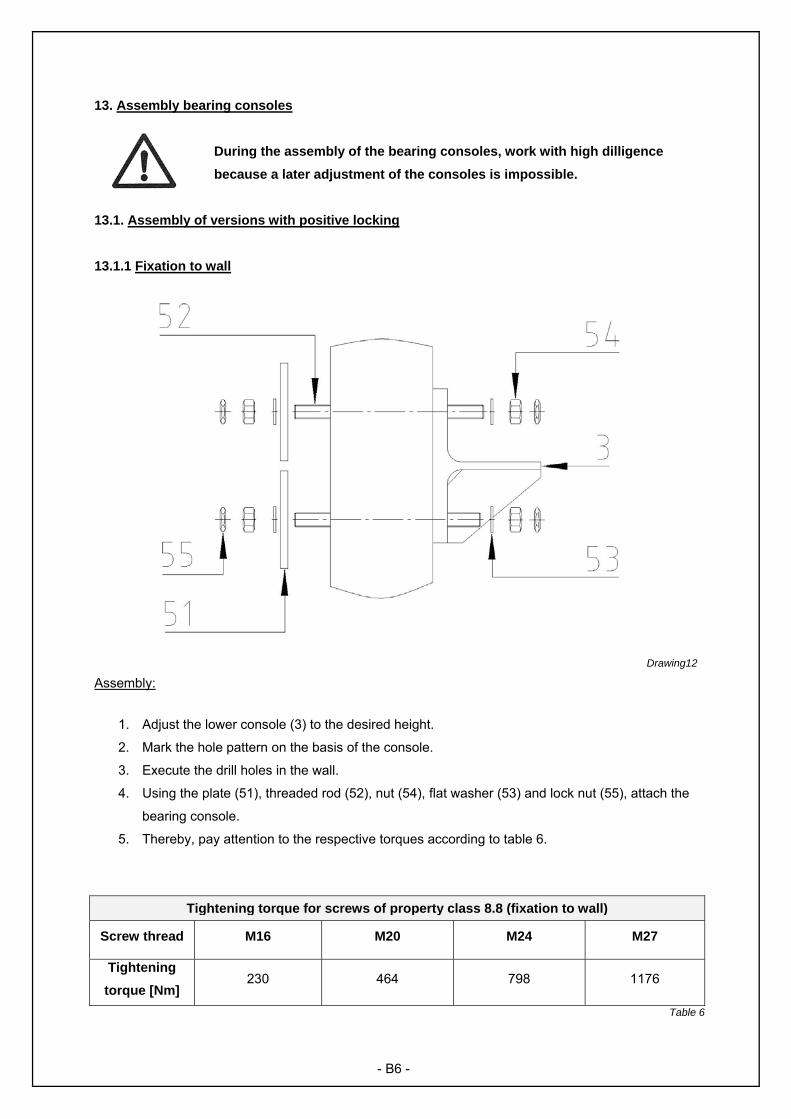
13.1. Assembly of versions with positive locking 13.1.1 Fixation to wall
Drawing12
Assembly:
1. Adjust the lower console (3) to the desired height.
2. Mark the hole pattern on the basis of the console.
3. Execute the drill holes in the wall.
4. Using the plate (51), threaded rod (52), nut (54), flat washer (53) and lock nut (55), attach the
bearing console.
5. Thereby, pay attention to the respective torques according to table 6.
Tightening torque for screws of property class 8.8 (fixation to wall)
Screw thread M16 M20 M24 M27
Tightening torque [Nm]
230 464 798 1176
Table 6
- B6 -
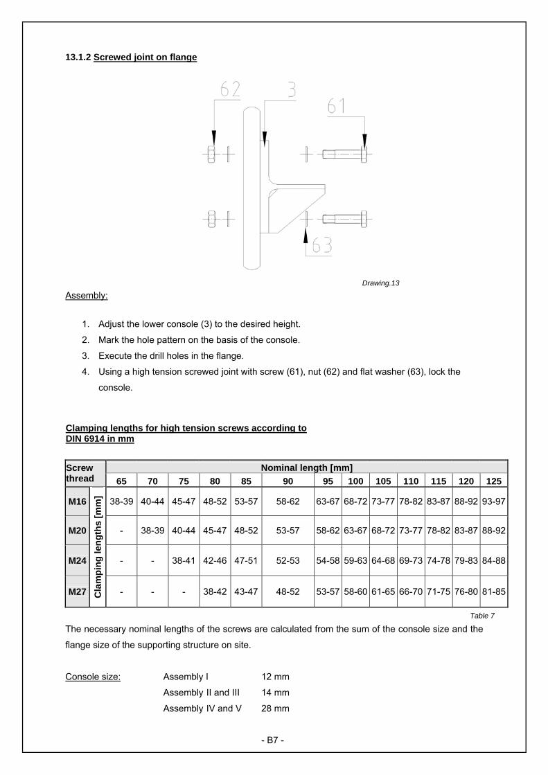
13.1.2 Screwed joint on flange
Assembly:
1. Adjust the lower console (3) to the desired height.
2. Mark the hole pattern on the basis of the console.
3. Execute the drill holes in the flange.
4. Using a high tension screwed joint with screw (61), nut (62) and flat washer (63), lock the
console.
Clamping lengths for high tension screws according to DIN 6914 in mm
Nominal length [mm] Screw thread 65 70 75 80 85 90 95 100 105 110 115 120 125
M16 38-39 40-44 45-47 48-52 53-57 58-62 63-67 68-72 73-77 78-82 83-87 88-92 93-97
M20 - 38-39 40-44 45-47 48-52 53-57 58-62 63-67 68-72 73-77 78-82 83-87 88-92
M24 - - 38-41 42-46 47-51 52-53 54-58 59-63 64-68 69-73 74-78 79-83 84-88
M27 Cla
mpi
ng le
ngth
s [m
m]
- - - 38-42 43-47 48-52 53-57 58-60 61-65 66-70 71-75 76-80 81-85
The necessary nominal lengths of the screws are calculated from the sum of the console size and the
flange size of the supporting structure on site.
Console size: Assembly I 12 mm
Assembly II and III 14 mm
Assembly IV and V 28 mm
Drawing.13
- B7 -
Table 7

13.1.3 Bolt anchorage
Assembly:
1. Using the threaded rod (73), flat washer (75) and nut (74), attach the bearing console (3) to
the bolt plate.
2. Mark the hole pattern on the basis of the bolt plate (71).
3. Execute the drill holes in the wall. Thereby, observe the information of the bolt fabricator.
4. Attach the lower bearing console (3) to the wall and thereby pay attention to the information of
the bolt fabricator.
Sizes of the screws and bolts shall be taken from the documents of the crane.
Please check the information on the additional master data list and observe the general technical
approvals of the bolts.
Drawing 14
- B8 -

13.2 Assembly of versions actuated by gravity
13.2.1 Support clasp
At the attachment of the bearing consoles by means of a connection actuated by
gravity it is important to lock the lower bearing consoles against slipping. For this
reason, fall protections shall be assembled during the assembly. Hereby, two variants
are possible.
Variants of the fall protection:
Attachment with bolts (concrete support) Attachment by welding ( I profile)
Assembly:
To concrete support:
1. Mark the hole pattern for the fall protection (82) in the desired heigth on the concrete
support and execute the necessary drill hole in the support. Please take the necessary
descriptions from the information of the bolt fabricator.
2. Using a stud bolt (81), attach the fall protection (82) to the concrete support.
3. Using the threaded rod (85), counter plate (83), flat washers (86) and nuts (87), attach the
lower bearing console (3) to the column.
4. Weld the locking devices (84) to the bearing console, so that those are flush with the
support. (field weld a=4mm)
To steel column (I profile):
1. Weld the fall protection (82) in the desired heigth to the column.
(hollow weld a=4mm)
2. Using the threaded rod (85), counter plate (83), flat washers (86) and nuts (87), attach
the lower bearing console (3) to the column.
3. Weld the locking device s (84) to the bearing console, so that those are flush with the
support. (field weld a=4mm)
Drawing 15
- B9 -

14. Assembly of the boom and the upper bearing console Before starting the assembly, clean the upper and lower sliding bearing (DU bush (100)) and remove
heavy solings on mechanical parts. The bearings are ex factory fitted to the boom tube and should not
be disassembled.
Drawing16
Assembly:
1. Lift the boom (1) carefully. Make sure that the boom is protected against fall and is lifted
horizontally.
2. Insert the slide ring (21) between lower bearing console and boom.
3. Insert the pre-assembled slewing brake between the guide brackets on the lower bearing
console (only with special equipment “slewing brake“).
4. Insert the boom (1) carefully into the lower console (3)
Caution! Danger of crushing!
5. Guide the swivel axis (20) to the drilled hole of the lower bearing console (3).
6. Put the upper bearing console (2) on the boom (1) and guide the swivel axis through the
drilled hole of the upper console (2).
7. Using a screw (120), flat washer (121), nut (122), attach the safety plate (22) to the boom.
8. Adjust the console till the swivel axis (20) is perpendicular.
9. In case of anchorage variant a), b), c): mark the hole pattern on the basis of the upper console
(2).
In case of anchorage variant d): Using the counter plate, threaded rods as well as flat washers
and nuts, the upper console shall be attached during the assembly.
10. Execute the drill holes in the supporting structure on site. [a),b),c)]
- B10 -

11. a) Fixation to wall: Using the plate (31), threaded rod (32), flat washer (33), nut (34) and
locking nut (35), the upper console shall be fixed.
Thereby, observe the respective torques according to table 6.
b) Screwed joint on flange: Lock the upper bearing console with high tension screwed joint.
Please take the sizes of the screwed joints from the documents of the crane.
c) Bolt anchorage: Using the incluted bolts, attach the upper bearing console. Thereby,
observe the information of the bolt fabricator.
15. Assembly of the equipment The supplementary equipment offered by us is the permitted equipment for the crane. We, as crane
manufacturer, adjust our equipment to the crane and certify the belonging in the inspection records on
the additional master data list. In addition, the crane is intended for the use with hoisting gears and
load handling devices which meet the national accident prevention regulations as well as the current
EC Machinery Directive. During the choice of the hoisting gears, the limitations according to chapter 1
(intended use) and the data sheets shall be observed.
15.1 Assembly of the hoisting gear
Review and decide in advance, if you pre-assemble the cross travel winch and the hoisting gear on
outside and hang it then into the boom of if the assembly of the hoisting gear should take place
directly on the boom. Assemble the hoisting gear and the travelling winch according to the individual
instructions of the respective manufacturer of hoisting gear. Ensure the correct adjustment of the
bottom flange carriage to the width of the mounting flange of the boom. Consider the clearance on the
crab gauge provided by the manufacturer of the hoisting gear.
Advice!
Observe the instructions of the manufacturer of hoisting gear!
Table 8
Possible arrangements (in direction to the head of the boom) Component
Left Centre Right
Chain box X Hoisting gear normal design X Carriage X Control switch on hoisting gear X Trailing cable X or X Round cable X or X Terminal box on boom Terminal box on carriage Terminal box on hoisting gear
Arrangement according to the point where the power supply is assembled
- B11 -

15.2 Assembly cross travel stops The inner cross travel stops are tightly connected ex works with the boom. The cross travel stop on
the head of the boom is removable. They are suitable as final position limitation for numerous cross
travel winches.
ADVICE: If the function of the cross travel stops is not ensured, universal cross travel
stops in clamping design are available as special equipment.
The following parts are loosely enclosed for the assembly of the cross travel stops: 1x Stop angle (23) 2x Rubber buffer (110) 2x Flat washer (111) 2x Hexagon nut (112) 2x Hexagon head screw (115) 4x Falt washer (116) 2x Hexagon nut (117)
Drawing17
Assembly: 1. Fix the stop angle (23) on the head of the boom using (115) to (117). 2. Fix the rubber buffer (110) on the stop angles using (111) and (112). By starting the carriage, ensure the function of the cross travel stops after the
assembly. CAUTION: Without cross travel stop on the head of the boom, the hoisting gear
(with load) moves from the boom danger of fall down of the load!!!
- B12 -

40.1
41.1
15.3 Assembly slewing brake The slew brake (special equipment) serves for the adjustment of the slewing rate of the boom. The
brake shoes equipped with a brake pad can be pressed on the slewing column via a manually fine
adjustable disc spring packet and as a result they avoid, according to pretension, the overtravel of the
boom.
Assembly: Drawing18
1. Position the both blocks (40.1) with the distance pieces (40.2) downwards on the lower
console between the guide plates intended for this purpose.
2. Attach 10 disc springs (40.12) in each case (according to drawing 18) on the screws (40.11)
and connect the both blocks using the scews and nuts (40.10).
3. The braking effect is adjusted by tightening the nuts (40.10) uniformly.
Is case of the subsequent equipment of cranes with slewing brakes it is necessary to refit guide plates
on the lower bearing console. In this case, please observe the separately available assembly
instructions.
15.4 Assembly slewing stops The sleving stops serves for the limitation of the slewing motion (special equipment).
15.4.1 Slewing stops in weldable design are provided as all-purpose
fixed stops on the base of boom.
The stops consist in each case of a steel profile (41.1) as well as of a
rubber buffer with stay bolts (41.10), a flat washer (41.11) and a
locking nut (41.12) for the fixation. During the welding, the rubber
buffers shall be removed from the profile.
- B13 -
40.12
40.11
40.240.3
40.10
Drawing19
41.10, 41.11, 41.12

Please review before assembly:
- Do you meet the requirements of welding on cranes?
- Allow the environmental conditions on assembly site a welding?
- Are all equipments, hoisting gears etc., relevant to define the slewing range,
assembled on the crane?
- Which interference contours in the environment of the crane shall be protected
against impact of the boom and how must the boom protected against impact?
- Decide on which point (Crane column or lower bearing plate) and in which position
(standing of lying) the universal stop must be welded to fulfil its function.
- In this connection, please take account to a maximum long weld seam (GWL design
size 1-3 minimum 75 mm, design size 4+5 minimum 120 mm).
Assembly:
1. In the area of the projected welded seam, remove locally the existing anti-corrosion
coating.
2. Attach the buffer (41.1) and check the intended function – if necessary, adjust the
position of the buffer.
3. Completely weld the buffer on (hollow weld a=3mm (I-III) and/or a=4mm (IV + V).
4. Using flat washer (41.11) and nut (41.12), assemble the rubber buffer (41.10).
5. Check the function of the stops with and without load on the respective final positions
of cross travel.
6. Using the included correction colour, renew the corrosion protection in the area oft he
welded seam.
15.4.2 Slewing stops with buffer rod are provided for the assembly in the area of the head of boom.
For reasons of the optimum load application the stops
provided for clamping on the upper flange or the end plate
shall
- Be assembled max. 300 mm before end of boom
- Take effect perpendiculary on a fixed counterplot in the
environment of the crane
Using the clamping shoe, clamp the slewing stops at the
desired position on the end of the boom. Make sure that the
slewing stops effect perpendiculary on the counterplot (walls,
column or similar).
- B14 -
Drawing 20

15.5 Assembly of the locking of boom The locking of the boom is intended for the fixation of the boom in one or more positions within the
swivelling range of the crane. At cranes for outdoor operation the locking is standard equipment and
serves for wind bracing (see also chapter 5.1.4)
The locking of the boom is pre-assembled ex works on the lower bearing console.
During the assembly locking of the boom
shall be adjusted in position “loosen”, to
ensure a smooth hanging in of the boom.
Therefor, turn the control rod (A1) to make
possible, that the return stop (A2) could be
guided through the drilled hole of the metal
plate. Afterwards, the locking shall be
turned so that the fastening bolt (A3) is fixed
and cannot be guided back through the
drilled hole of the metal plate. In this
position, the fastening bolt (A3) is loose and
not positioned in the locking bracket (A5).
After assembly of the boom (see chapter
14), the locking shall be checked for right
function.
During maintenance and repair works, it
could be necessary to disassemble the
locking to replace for example the spiral
spring. In this case the bolt (pos. A2 and A6
– called return stop) must be replaced and
the control rod can be pulled downwards out
of the guide plates. Remove spring and flat washer carefully. Caution – the return spring could be
under pre-tension.
The assembly proceeds in reverse order. Position the new spring (A4) and the new flat washer (A7)
between the plates and the control rod into the drilling holes of the guide plates. Lock it with bolt (A2
and A6) and, after assembly, check locking for function.
Drawing21
- B15 -

16. Assembly of the electricity Standard electricity Equipment:
• Rising main • Main switch Basic electricity • Grounding unit for swivel column + boom • The power supply to the hoisting gear on the boom is ensured via round cable or trailing cable
Round cable power supply
Trailing cable power supply Drawing 22
• The hoisting gear is controlled via a control switch which is directly attached to the hoisting gear. Safety instructions
In case of faulty electric power supplies there is the risk of an accident, maybe a
danger for life and limb is also possible. Never act without thinking, it is impossible to
replace a human life.
Only electricians may create electrical connections!
Observe the currently valid directives:
- UVV BGV D6
- DIN VDE 0100
- DIN EN 60204-32
- DIN VDE 0100-600
Observe the safety instructions:
- Power off
- Ensure zero potential
- Protect main switch against unauthorised switch-on (e.g. padlock)
- Pay attention to right tension and rotating direction.
In case of emergency, push the EMERGENCY BUTTON on the control swith or cut
the electric power on main switch off.
- B16 -

16.1 Assembly of the base electricity
After the boom is assembled, it is possible to connect
the base electricity. Therefore a terminal box with an
applicable round cable is pre-assembled on the boom. Guide the round cable through the applicable screw
connection on the crane column in the tube downwards
to the main switch.
Drawing 23 16.2 Assembly of the main switch
Assembly:
1. Attach the lower case of the main switch on the provided point of the supporting structure on
site below the boom in a height of 1.20 m above floor. In case of a fixation to wall, the main
switch shall be attached with a countersunk head wood screw (226) and an expansion anchor
(225).
2. As next step, attach the protective earth conductor of the power supply to the terminal block
(with grounding symbol).
- B17 -
Drawing 24
224
225, 226
223
Round cable Flat cable
Terminal box

3. Attach the protective earth conductor of the round cable to the terminal block.
4. Afterwards, attach the 3 phase cables of the round cable to the switch module according to
the marking on the respective cable on the positions T1, T2, T3.
5. Now, connect the 3 phase cables of the power supply with the switch module on the positions
L1, L2, L3. Make sure that the switch is opened (position OFF)
6. Close the main switch by fixing the upper case to the lower case, using the countersunk
screws.
16.3 Assembly grounding unit on boom (Only for design with trailing cable)
Drawing 25
Assembly:
1. Attach one end of the protective earth conductor (218) with cylinder head screw (216),
hexagon head screw (217), flat washer (221) and lock washer (220) to the terminal box of the
boom.
2. Attach one end of the protective earth conductor (218) on the terminal block of the terminal
box (214). Make sure that the green/yellow marked cables are connected opposite.
- B18 -

16.4 Power supply via trailing cable
Description:
The flat cable (213) runs parallel to the boom (1) through the running rail (205) and is connected
between terminal box (214) and terminal block to the hoisting gear. The length of the flat cable
amounts 1.4 times the boom. It is arranged ex works on the right side of the boom in the direction to
end of boom. Designs with arrangement on the left side are possible in special design.
Assembly:
1. Using the clamping shoes (202), clamp the support console (201) to the boom.
(maximum distance between the support consoles amounts to 2m)
2. Attach the fixed mounting bracket (204) to the support console (201).
3. Insert the running rail (205) into the fixed mounting bracket (204).
4. Attach the termination fitting (210) to the running rail (205)
5. Run the carrier (209) and the piped wagons (208) in the running rail (205) and fix the end cap
(211) to the end of the running rail.
6. Unscrew the screw on piped wagon (208), carrier (209) and termination fitting (210).
7. Guide the flat cable (213) through termination fitting (210), piped wagon (208) and carrier
(209). The distances between the piped wagons amount to 2x the cable sag.
8. Divide the flat cable (213) in equal distances.
9. Tighten the srews, unscrewed under point 6
10. Drive the hoisting gear carefully to the end of the boom till the cross travel stop.
11. Connect the flat cable (213) with the terminal block of the hoisting gear.
12. Using a screw (43.12) and a spring washer (43.13), assemble the carrier (43) to the carriage
of the hoisting gear.
- B19 -
Drawing 26

16.5 Power supply via round cable
Description:
The round cable (308) is located up to the half length of the boom in the armoured steel tube (309)
and connected with the terminal block of the hoisting gear. The free cable sag is ¼ of the boom
length. The armoured steel tube (310) and the armoured steel crown (311) are fixed with a Stauff
clip (312). It is arranged ex works on the right side of the boom in the direction to end of boom.
Arrangements on the left side are possible in special design.
Drawing 27
Montage:
1. The armoured steel tube (309) is pre-assembled on the boom.
2. Screw the armoured steel crown (311) on the armoured steel tube (310)
3. Using the Schauff clip (313) attach the short armoured steel tube (310) and the armoured
steel crown (311) on the boom.
4. Guide the round cable (308) through the armoured steel tube (309) and (310), through the
armoured steel crown (311) to the terminal block of the hoisting gear.
5. Drive the hoisting gear to the end of the boom and connect the round cable with the terminal
block of the hoisting gear according to the instructions of the hoisting gear manufacturer.
On the ultimate position of the hoisting gear, the round cable hangs freely and/or sags a bit.
(No tractive forces to the connections!)
- B20 -

17. Information on the adjustment A correctly adjusted crane with hoisting gear in stand-by position (on the end of the boom close by the
bearing consoles) and with hook in upper position at the desired working or stand by positions should
not start unintended.
Load the crane with nominal load and drive all possible courses of motions with this load in order to be
able to take into account the manufacture or assembly related settling of the crane unit or anchorages.
The causes of uncontrolled boom movement of manual operated booms could be due to the system.
That means that they are caused by supporting structures (walls, supports). Check, how the
uncoltrolled boom movement could derange or endanger the operating procedure. Please note, that
unguided loads hanging on the crane (this also could be slinging means, traverses or several) do not
meet the requirements of the intended use and require, if necessary, special equipment.
In case that the uncontrolled boom movement disturbs and/or impacts the security or the operation
and if the adjustment results no improvements, in most cases, a slewing brake (special equipment)
could help.
18. Start of operation
Commissioning of the crane
Take protocol of the commissioning! The following points shall be observed at commissioning:
Electrical connection Checked by electrician? (VDE 0100 – 600)
Screw fittings Safe and fixed?
Ropes and chains Secured on start and end, lubricated and greased?
Cross travel stops Attached on boom end?
Boom Axle support (Pos. 22) attached?
Slewing brake Checked for correct operation?
Boom locking Safe and functioning?
Power supply Free movement of the hoisting gear possible?
Foot flange Bottom casting existing?
Coating Correct damages?
Hoisting gear Observe manufacturer’s operating manual!
Documentation Hand included documents over!
Assembly site Cleaned up?
Labelling Complete?
Check the crane functions without load:
Working area Hindered?
Slewing range Limited?
Satefy distances Are they observed?
Function Crane, end switch, additional equipment? Test load If the evaluation is not clear, load the crane with nominal load!
- B21 -
Is it possible to start the crane? Responsibility of acceptance: All cranes ≥ 1000 kg load bearing capacity All cranes ≤ 1000 kg, from 2 power driven movements
Before initial operation and after significant modifications, power driven cranes must be checked by an
authorised expert before recommissioning. This also applies for manual or partly power driven cranes
with a load bearing capacity of more than 1000 kg.
The acceptance shall take place in compliance with BGG 905 “Principles for the inspection of cranes“
according to UVV BGV D6 “Cranes“.
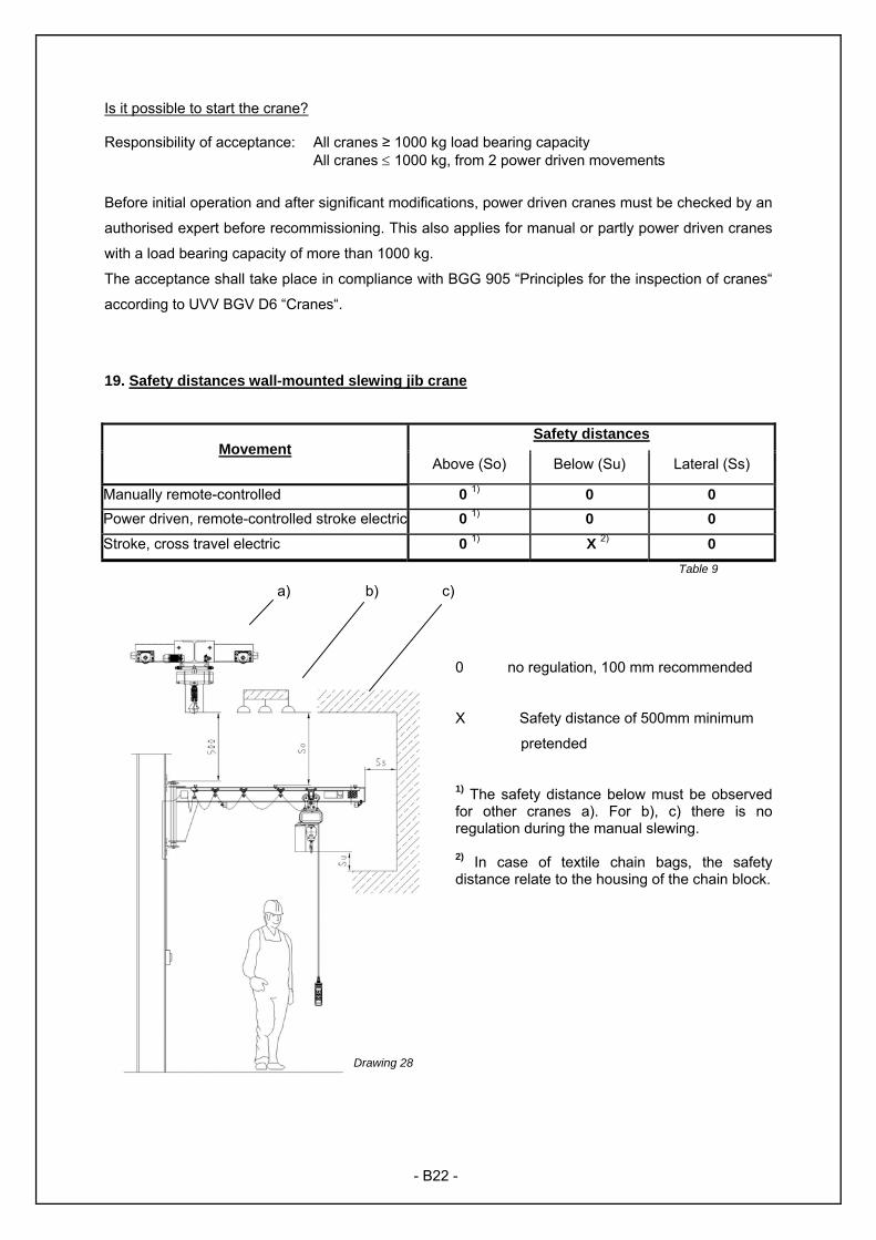
19. Safety distances wall-mounted slewing jib crane
Safety distances Movement
Above (So) Below (Su) Lateral (Ss)
Manually remote-controlled 0 1) 0 0 Power driven, remote-controlled stroke electric 0 1) 0 0 Stroke, cross travel electric 0 1) X 2) 0
Table 9 a) b) c)
0 no regulation, 100 mm recommended
X Safety distance of 500mm minimum
pretended
1) The safety distance below must be observed for other cranes a). For b), c) there is no regulation during the manual slewing. 2) In case of textile chain bags, the safety distance relate to the housing of the chain block.
Drawing 28
- B22 -

20. Additions and notes
- B23 -
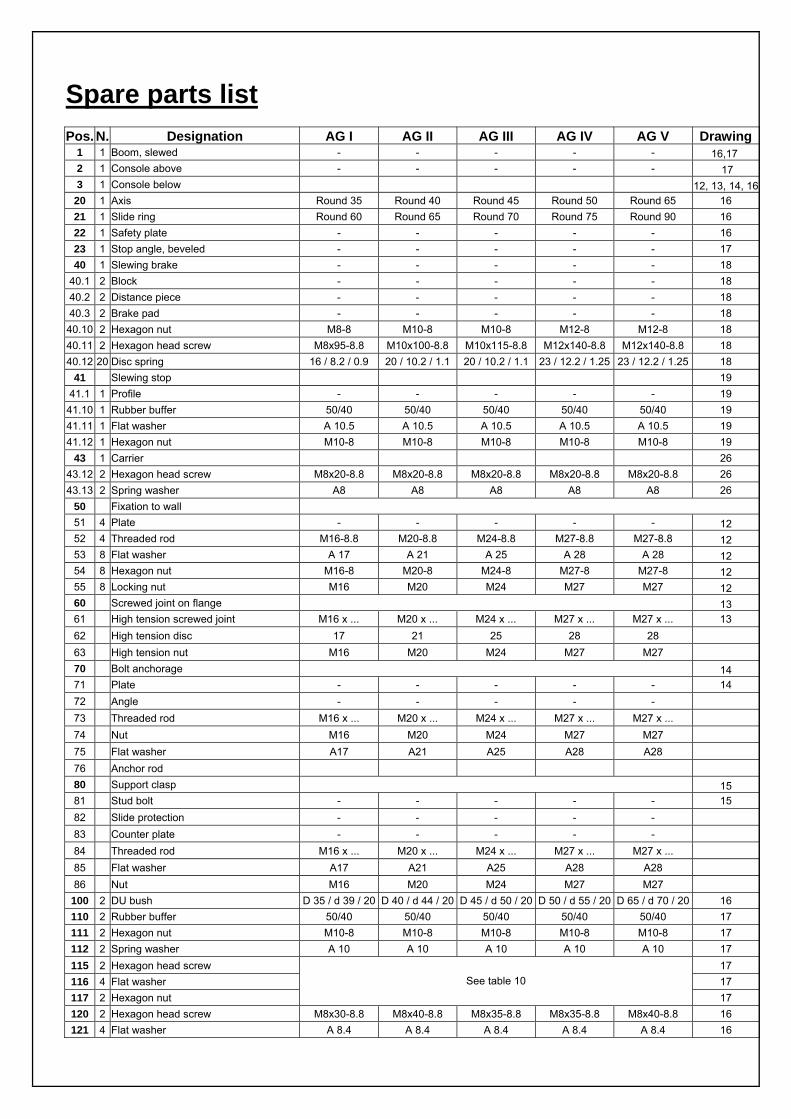
Spare parts list
Pos. N. Designation AG I AG II AG III AG IV AG V Drawing1 1 Boom, slewed - - - - - 16,17 2 1 Console above - - - - - 17 3 1 Console below 12, 13, 14, 16
20 1 Axis Round 35 Round 40 Round 45 Round 50 Round 65 16 21 1 Slide ring Round 60 Round 65 Round 70 Round 75 Round 90 16 22 1 Safety plate - - - - - 16 23 1 Stop angle, beveled - - - - - 17 40 1 Slewing brake - - - - - 18
40.1 2 Block - - - - - 18 40.2 2 Distance piece - - - - - 18 40.3 2 Brake pad - - - - - 18
40.10 2 Hexagon nut M8-8 M10-8 M10-8 M12-8 M12-8 18 40.11 2 Hexagon head screw M8x95-8.8 M10x100-8.8 M10x115-8.8 M12x140-8.8 M12x140-8.8 18 40.12 20 Disc spring 16 / 8.2 / 0.9 20 / 10.2 / 1.1 20 / 10.2 / 1.1 23 / 12.2 / 1.25 23 / 12.2 / 1.25 18
41 Slewing stop 19 41.1 1 Profile - - - - - 19
41.10 1 Rubber buffer 50/40 50/40 50/40 50/40 50/40 19 41.11 1 Flat washer A 10.5 A 10.5 A 10.5 A 10.5 A 10.5 19 41.12 1 Hexagon nut M10-8 M10-8 M10-8 M10-8 M10-8 19
43 1 Carrier 26 43.12 2 Hexagon head screw M8x20-8.8 M8x20-8.8 M8x20-8.8 M8x20-8.8 M8x20-8.8 26 43.13 2 Spring washer A8 A8 A8 A8 A8 26
50 Fixation to wall 51 4 Plate - - - - - 12 52 4 Threaded rod M16-8.8 M20-8.8 M24-8.8 M27-8.8 M27-8.8 12 53 8 Flat washer A 17 A 21 A 25 A 28 A 28 12 54 8 Hexagon nut M16-8 M20-8 M24-8 M27-8 M27-8 12 55 8 Locking nut M16 M20 M24 M27 M27 12 60 Screwed joint on flange 13 61 High tension screwed joint M16 x ... M20 x ... M24 x ... M27 x ... M27 x ... 13 62 High tension disc 17 21 25 28 28 63 High tension nut M16 M20 M24 M27 M27 70 Bolt anchorage 14 71 Plate - - - - - 14 72 Angle - - - - - 73 Threaded rod M16 x ... M20 x ... M24 x ... M27 x ... M27 x ... 74 Nut M16 M20 M24 M27 M27 75 Flat washer A17 A21 A25 A28 A28 76 Anchor rod 80 Support clasp 15 81 Stud bolt - - - - - 15 82 Slide protection - - - - - 83 Counter plate - - - - - 84 Threaded rod M16 x ... M20 x ... M24 x ... M27 x ... M27 x ... 85 Flat washer A17 A21 A25 A28 A28 86 Nut M16 M20 M24 M27 M27
100 2 DU bush D 35 / d 39 / 20 D 40 / d 44 / 20 D 45 / d 50 / 20 D 50 / d 55 / 20 D 65 / d 70 / 20 16 110 2 Rubber buffer 50/40 50/40 50/40 50/40 50/40 17 111 2 Hexagon nut M10-8 M10-8 M10-8 M10-8 M10-8 17 112 2 Spring washer A 10 A 10 A 10 A 10 A 10 17 115 2 Hexagon head screw 17 116 4 Flat washer 17 117 2 Hexagon nut
See table 10 17
120 2 Hexagon head screw M8x30-8.8 M8x40-8.8 M8x35-8.8 M8x35-8.8 M8x40-8.8 16 121 4 Flat washer A 8.4 A 8.4 A 8.4 A 8.4 A 8.4 16
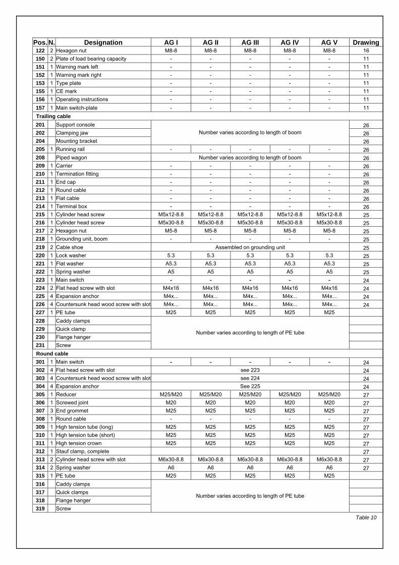
Pos. N. Designation AG I AG II AG III AG IV AG V Drawing122 2 Hexagon nut M8-8 M8-8 M8-8 M8-8 M8-8 16 150 2 Plate of load bearing capacity - - - - - 11 151 1 Warning mark left - - - - - 11 152 1 Warning mark right - - - - - 11 153 1 Type plate - - - - - 11 155 1 CE mark - - - - - 11 156 1 Operating instructions - - - - - 11 157 1 Main switch-plate - - - - - 11
Trailing cable 201 Support console 26 202 Clamping jaw 26 204 Mounting bracket
Number varies according to length of boom
26 205 1 Running rail - - - - - 26 208 Piped wagon Number varies according to length of boom 26 209 1 Carrier - - - - - 26 210 1 Termination fitting - - - - - 26 211 1 End cap - - - - - 26 212 1 Round cable - - - - - 26 213 1 Flat cable - - - - - 26 214 1 Terminal box - - - - - 26 215 1 Cylinder head screw M5x12-8.8 M5x12-8.8 M5x12-8.8 M5x12-8.8 M5x12-8.8 25 216 1 Cylinder head screw M5x30-8.8 M5x30-8.8 M5x30-8.8 M5x30-8.8 M5x30-8.8 25 217 2 Hexagon nut M5-8 M5-8 M5-8 M5-8 M5-8 25 218 1 Grounding unit, boom - - - - - 25 219 2 Cable shoe Assembled on grounding unit 25 220 1 Lock washer 5.3 5.3 5.3 5.3 5.3 25 221 1 Flat washer A5.3 A5.3 A5.3 A5.3 A5.3 25 222 1 Spring washer A5 A5 A5 A5 A5 25 223 1 Main switch - - - - - 24 224 2 Flat head screw with slot M4x16 M4x16 M4x16 M4x16 M4x16 24 225 4 Expansion anchor M4x... M4x... M4x... M4x... M4x... 24 226 4 Countersunk head wood screw with slot M4x... M4x... M4x... M4x... M4x... 24 227 1 PE tube M25 M25 M25 M25 M25 228 Caddy clamps 229 Quick clamp 230 Flange hanger 231 Screw
Number varies according to length of PE tube
Round cable 301 1 Main switch - - - - - 24 302 4 Flat head screw with slot see 223 24 303 4 Countersunk head wood screw with slot see 224 24 304 4 Expansion anchor See 225 24 305 1 Reducer M25/M20 M25/M20 M25/M20 M25/M20 M25/M20 27 306 1 Screwed joint M20 M20 M20 M20 M20 27 307 3 End grommet M25 M25 M25 M25 M25 27 308 1 Round cable - - - - - 27 309 1 High tension tube (long) M25 M25 M25 M25 M25 27 310 1 High tension tube (short) M25 M25 M25 M25 M25 27 311 1 High tension crown M25 M25 M25 M25 M25 27 312 1 Stauf clamp, complete 27 313 2 Cylinder head screw with slot M6x30-8.8 M6x30-8.8 M6x30-8.8 M6x30-8.8 M6x30-8.8 27 314 2 Spring washer A6 A6 A6 A6 A6 27 315 1 PE tube M25 M25 M25 M25 M25 316 Caddy clamps 317 Quick clamps 318 Flange hanger 319 Screw
Number varies according to length of PE tube
Table 10

Flange width [mm] Hexagon head screw Flat washer Hexagon nut 64 M8 x 30 - 8.8 A 8,4 M8 - 8 73 M10 x 30 - 8.8 A11 M10 - 8 82 M10 x 30 - 8.8 A11 M10 - 8 91 M12 x 40 - 8.8 A13 M12 - 8 100 M12 x 40 - 8.8 A13 M12 - 8 110 M12 x 40 - 8.8 A13 M12 - 8 120 M12 x 40 - 8.8 A13 M12 - 8 135 M16 x 45 - 8.8 A17 M16 - 8 150 M16 x 45 - 8.8 A17 M16 - 8 160 M16 x 45 - 8.8 A17 M16 - 8 170 M16 x 45 - 8.8 A17 M16 - 8 180 M16 x 45 - 8.8 A17 M16 - 8
Table 11

COLUMBUS McKINNON Engineered Products GmbH Am Silberpark 2-8 86438 Kissing/Germany
Telefon: +49 8233 2121-0 Telefax: +49 8233 2121-805 www.pfaff-silberblau.com
EG-Konformitäts-erklärung
im Sinne der EG-Maschinen-richtlinie 2006/42/EG, Anhang
II, Nr. 1A
EC-Declaration of Conformity
as defined by EC Machinery Directive 2006/42/EC,
annex II, No. 1A
Déclaration "CE" de Conformité
conformément à la directive "CE" relative aux machines
2006/42/CE, Annexe II No. 1A Hiermit erklären wir, dass Herewith we declare that the supplied model of Nous déclarons que le modèle
Wandschwenkkran WSK Wall-mounted slewing jib
crane WSK Potence murale avec
commande pivotant WSK
Type GWL zum Heben, Senken und Bewe-
gen von Lasten for lifting, lowering and moving
of loads pour lever, baisser et deplacer
des charges
mit allen einschlägigen Bestimmungen der EG Maschinenrichtlinie 2006/42/EG in Übereinstimmung ist
complies with the relevant provisions of the EC Machinery directive 2006/42/EC applying to it
est conforme à l’ensemble des dispositions selon la directive 2006/42/CE relative aux machines
Die Maschine ist auch in Übereinstimmung mit allen einschlägigen Bestimmungen der folgenden EG-Richtlinien:
The engine is also in agreement with all relevant regulations of the following EC directives:
L’appareil est également conforme aux dispositions selon les directives européennes suivants :
EG-Niederspannungsrichtlinie 2006/95/EG
EG-Richtlinie EMV 2004/108/EG
Low voltage directive 2006/95/EC
EMC Directive 2004/108/EC
Directive „Basse tension“ 2006/95/CE
Directive „Compatibilité électromagnétique“ 2004/108/CE
Angewendete harmonisierte Normen, insbesondere:
Applied harmonised standards, in particular: Normes harmonisées utilisées, notamment
DIN EN ISO 12100-1; DIN EN ISO 12100-2; EN 60204 T 32 ; DIN EN 13001-1; DIN EN 13001-2; DIN EN 13001-3-1;
Angewendete nationale Normen und technische Spezifikationen, insbesondere:
Applied national technical standards and specifications, in particular:
Normes et spécifications techniques nationales qui ont été utilisées, notamment
BGV A1; BGV D6; BGV D8; DIN 15018-Teil 1 und Teil 2; DIN 15019 Teil 1; DIN 1045;
Die EG-Konformitätserklärung gilt für betriebsfertig gem. Montageanleitung, errichtete Krane, deren ordnungsgemäße Aufstellung und Prüfung bescheinigt ist.
Diese Konformitätserklärung erlangt ihre Gültigkeit nach vollständig abgeschlossener und dokumentier-ter Montage gem. Montageanleitung und mängel-freier, dokumentierter Prüfung vor der ersten Inbe-triebnahme. Die bauseitige Tragkonstruktion ist nicht Gegenstand dieser Erklärung. Für einen sicheren Kranbetrieb ist aber ausreichende Tragfähigkeit und Steifigkeit der Tragkonstruktion erforderlich.
This declaration of conformity only becomes valid after the assembly has been completed and docu-mented in accordance with the assembly instructions and after faultless, documented checking before the first start-up. The support structure provided by the customer is not a subject of this declaration. However, the load-bearing capacity and rigidity of the support structure must be adequate in order to ensure safe crane op-eration.
Cette déclaration de conformité ne devient valable qu’après un montage totalement terminé et docu-menté, conformément aux instructions de montage et un contrôle documenté sans défaut avant la pre-mière mise en service. L’appareil porteur sur le site ne fait pas l’objet de cette déclaration. Cependant, pour que la grue fonc-tionne en toute sécurité, il est nécessaire que l’appareil porteur ait une limite de charge suffisante et une rigidité.
Ort/Datum Kissing, 01.04.2011
ppa. Ulrich Hintermeier i.V. Konrad Ertl Der Unterzeichnende ist bevollmächtigt die technischen Unterlagen gem. Anhang VII A zusammenzustellen und der zuständigen Behörde auf Verlangen zu übermitteln.
The signing is authorised to put together the technical documents in accordance with appendix VII A and to transmit to the responsible authority on demand.
Le signant est habilité à rassembler les documents techniques selon l'annexe VII A et à les transmettre, sur demande, aux autorités compétentes.
Komplettierung, Montage, Probebetrieb und Sachkundigenprüfung/Sachverständigen, vor Inbetriebnahme wurde durchgeführt. Die Prüfung ist im Prüfprotokoll (siehe Anhang) eingetragen.
Ort: ........................................................................ Datum: ..................................................................
Verantwortlicher: ...................................................... Firma: .......................................................................

COLUMBUS McKINNON Engineered Products GmbH Am Silberpark 2-8 86438 Kissing/Germany
Telefon: +49 8233 2121-0 Telefax: +49 8233 2121-805 www.pfaff-silberblau.com
Prüfnachweis Inspection Certificate / Certificat d’inspection
Datum der Inbetriebnahme:
Date of commissioning / Date de la mise en sevice
Prüfung vor der ersten Inbetriebnahme:
Inspection prior to first commissioning Inspection avant la première mise en service
durch:
by / par Firmenstempel / company stamp / cachet d’entreprise
Sachverständiger / Competent person / expert Sachkundiger
Wiederkehrende Prüfungen Regular Inspections / Inspections régulières
Prüfdatum Inspection Date
Date d’inspection
Befund Result / Résultat
Unterschrift des Sachkun-digen/Sachverständiger
Signature of a competent inspector
Signature de l’expert
Mängel behoben Defects eliminated am durch on by le par

Alle Standorte finden Sie auf / All locations can be found at
www.pfaff-silberblau.com
D
COLUMBUS McKINNON Engineered Products GmbH Am Silberpark 2-8 86438 Kissing GERMANY Telefon +49 8233 2121-0 Telefax +49 8233 2121-805 [email protected] www.cmco.eu/pfaff-silberblau
Händler: Merchant / commerçant Firmenstempel/stamp/cachet de la maison
Bei Inbetriebnahme Typenschilddaten eintragen:
Note name-plate data when taking into operation:
Inscrire les données sur la plaque du constructeur pendant l’utilisation :
Prüf.- Nr. Test no. No. de vérification Type Type Type Art. Nr. Art. No. Réf. de l’article Basismodell Base model Modèle de base Geräte/Fabrik-Nr. Device / Serial number Numéro de série Baujahr Year of manufacture Année de construction Hublast Capacity Capacité