Walking Experiment of Biped Robot with Antagonistic ... · Walking Experiment of Biped Robot with...
5
1 Abstract—The purpose of this research is to develop a biped robot with antagonistic actuation. An antagonistic actuation mechanism based on the human musculoskeletal structure was applied to the hip joint of the developed walking robot. SAT(Stiffness Adjustable Tendon) was attached at the actuation mechanism of the developed biped robot. The antagonistic actuation was realized by using motor and wire with SAT. A control algorithm utilizing the antagonism for walking motion was proposed and applied to the walking experiment by using the developed robot. The results of the walking experiment conducted using the proposed control algorithm are presented and discussed. Index Terms—Biped walking robot, Antagonistic actuation, Semi-passive walking, Walking experiment, Stiffness adjustable tendon I. INTRODUCTION OR the walking motion of biped robots, the two main technologies of actuation and feedback control are essential. For example, in the cases of ASIMO [1] and HRP-4 [2], a harmonic gear mechanism and ZMP (zero moment point)-based control have been employed. These robots had succeeded in continuous walking. However, the energy efficiency associated with the walking motion of typical biped robots is known to be worse than that of humans [3]. Besides, their motion is not compliant owing to their actuation mechanism of high reduction ratio. Passive walking is considered as a potential approach to solving the energy efficiency problem [4, 5]. The legs of a passive walking robot follow a pendulum-like motion by using gravitational energy, thus allowing the robots to walk continuously. Therefore, passive walking robots can walk without any actuators and controls on shallow slopes with certain initial conditions. This implies that from the energy efficiency viewpoint, passive walking robots are superior to typical walking robots with ZMP-based control. However, passive walking robots cannot walk on horizontal surfaces because they have no actuators and controls. Semi-passive walking robots utilizing the pendulum theory with minimal number of actuators have been Manuscript received December 9, 2015; revised December 20, 2015. This work was supported by JSPS KAKENHI Grant Number 26420201. Every author is with Mechanical Engineering Course, Graduate School of Science and Engineering, Ehime University, 3 Bunkyo-cho, Matsuyama, Ehime, 790-8577, Japan. Takashige Yano (e-mail: [email protected]). Jae Hoon Lee (e-mail: [email protected]). Shingo Okamoto (e-mail: [email protected]). considered for walking on horizontal surfaces in previous research works [6, 7]. This walking strategy realizes human-like walking based on passive walking. Recently, much attention has been paid to mimicking human structure, especially the musculoskeletal structure and its antagonistic actuation. Humans can adaptively adjust elasticity of the musculoskeletal structure by controlling the corresponding muscle tension. Thus, various types of human motion, such as walking, jumping, and running, could be performed. In addition, walking energy efficiency has been reported to improve by using musculoskeletal structure-like design [8]. Biped robots with musculoskeletal structure have been developed as well [9, 10]. Previously, we analyzed the model of a 1-DOF antagonistic actuation unit with a musculoskeletal structure [11, 12]. Simulation of motion and experiments by using the proposed control method and the calculation were also performed. Moreover, a semi-passive walking robot with antagonistic actuation was designed and developed in our previous research [13]. The control algorithm utilizing passive walking theory was proposed and embedded to the developed robot system. Those were tested through the walking experiments. Resultantly, it was shown in the experiment that the developed robot with antagonistic actuation can walk on the horizontal ground. Furthermore, its capability is similar to that of the previous research with no antagonistic actuation [6]. To control the stiffness of the robot, a particular spring with non-linear elasticity such as SAT (Stiffness Adjustable Tendon) is needed [14]. This paper deals with a method to utilize a SAT in the antagonistic actuator of the robot developed previous research. In addition, a control algorithm utilizing antagonism for walking motion is proposed. Walking Experiment of Biped Robot with Antagonistic Actuation Using Non-Linear Spring Takashige Yano, Jae Hoon Lee, Member, IAENG and Shingo Okamoto F Fig. 1. The model of the biped walking robot with antagonistic actuation Proceedings of the International MultiConference of Engineers and Computer Scientists 2016 Vol I, IMECS 2016, March 16 - 18, 2016, Hong Kong ISBN: 978-988-19253-8-1 ISSN: 2078-0958 (Print); ISSN: 2078-0966 (Online) IMECS 2016
Transcript of Walking Experiment of Biped Robot with Antagonistic ... · Walking Experiment of Biped Robot with...

1
Abstract—The purpose of this research is to develop a biped
robot with antagonistic actuation. An antagonistic actuation
mechanism based on the human musculoskeletal structure was
applied to the hip joint of the developed walking robot.
SAT(Stiffness Adjustable Tendon) was attached at the
actuation mechanism of the developed biped robot. The
antagonistic actuation was realized by using motor and wire
with SAT. A control algorithm utilizing the antagonism for
walking motion was proposed and applied to the walking
experiment by using the developed robot. The results of the
walking experiment conducted using the proposed control
algorithm are presented and discussed.
Index Terms—Biped walking robot, Antagonistic actuation,
Semi-passive walking, Walking experiment, Stiffness adjustable
tendon
I. INTRODUCTION
OR the walking motion of biped robots, the two main
technologies of actuation and feedback control are
essential. For example, in the cases of ASIMO [1] and HRP-4
[2], a harmonic gear mechanism and ZMP (zero moment
point)-based control have been employed. These robots had
succeeded in continuous walking.
However, the energy efficiency associated with the
walking motion of typical biped robots is known to be worse
than that of humans [3]. Besides, their motion is not
compliant owing to their actuation mechanism of high
reduction ratio. Passive walking is considered as a potential
approach to solving the energy efficiency problem [4, 5]. The
legs of a passive walking robot follow a pendulum-like
motion by using gravitational energy, thus allowing the
robots to walk continuously. Therefore, passive walking
robots can walk without any actuators and controls on
shallow slopes with certain initial conditions. This implies
that from the energy efficiency viewpoint, passive walking
robots are superior to typical walking robots with ZMP-based
control. However, passive walking robots cannot walk on
horizontal surfaces because they have no actuators and
controls. Semi-passive walking robots utilizing the pendulum
theory with minimal number of actuators have been
Manuscript received December 9, 2015; revised December 20, 2015.
This work was supported by JSPS KAKENHI Grant Number 26420201. Every author is with Mechanical Engineering Course, Graduate School of
Science and Engineering, Ehime University, 3 Bunkyo-cho, Matsuyama,
Ehime, 790-8577, Japan. Takashige Yano (e-mail: [email protected]).
Jae Hoon Lee (e-mail: [email protected]).
Shingo Okamoto (e-mail: [email protected]).
considered for walking on horizontal surfaces in previous
research works [6, 7]. This walking strategy realizes
human-like walking based on passive walking.
Recently, much attention has been paid to mimicking
human structure, especially the musculoskeletal structure and
its antagonistic actuation. Humans can adaptively adjust
elasticity of the musculoskeletal structure by controlling the
corresponding muscle tension. Thus, various types of human
motion, such as walking, jumping, and running, could be
performed. In addition, walking energy efficiency has been
reported to improve by using musculoskeletal structure-like
design [8]. Biped robots with musculoskeletal structure have
been developed as well [9, 10]. Previously, we analyzed the
model of a 1-DOF antagonistic actuation unit with a
musculoskeletal structure [11, 12]. Simulation of motion and
experiments by using the proposed control method and the
calculation were also performed. Moreover, a semi-passive
walking robot with antagonistic actuation was designed and
developed in our previous research [13]. The control
algorithm utilizing passive walking theory was proposed and
embedded to the developed robot system. Those were tested
through the walking experiments. Resultantly, it was shown
in the experiment that the developed robot with antagonistic
actuation can walk on the horizontal ground. Furthermore, its
capability is similar to that of the previous research with no
antagonistic actuation [6].
To control the stiffness of the robot, a particular spring
with non-linear elasticity such as SAT (Stiffness Adjustable
Tendon) is needed [14]. This paper deals with a method to
utilize a SAT in the antagonistic actuator of the robot
developed previous research. In addition, a control algorithm
utilizing antagonism for walking motion is proposed.
Walking Experiment of Biped Robot
with Antagonistic Actuation
Using Non-Linear Spring
Takashige Yano, Jae Hoon Lee, Member, IAENG and Shingo Okamoto
F
Fig. 1. The model of the biped walking robot
with antagonistic actuation
Proceedings of the International MultiConference of Engineers and Computer Scientists 2016 Vol I, IMECS 2016, March 16 - 18, 2016, Hong Kong
ISBN: 978-988-19253-8-1 ISSN: 2078-0958 (Print); ISSN: 2078-0966 (Online)
IMECS 2016
II. CONFIGURATION OF THE BIPED WALKING ROBOT
A. Model of biped walking robot
Figure 1 shows the model of the walking robot. The model
was derived based on the previously published research [6, 7].
The model is a three-linked planar system comprising two
legs and a torso. The control torques between the torso and
each leg are generated by two antagonistic wires connected to
the pulley of the DC motors on the torso link. The pulling
force of each wire is generated by the torque for winding up
the motor. It mimics the antagonistic actuation of the human
musculoskeletal structure. The angles 𝜃1 and 𝜃2 are the right
and left leg angles, respectively. The quantities 𝜏1 and 𝜏2
denote the control torques for both legs generated by the
motors connected by the wires. The angle 𝜃3 is the pitch
angle of the torso with respect to the vertical direction.
B. Mechanism of the biped walking robot
Figure 2 shows the developed robot in this research. The
robot has two pairs of legs and one torso. To constrain the
walking motion to the vertical planar space, each leg in
Figure 1 was designed as a pair of two parallel links. The
inner legs were connected to each other by additional frame.
The outer legs were fixed on the hip shaft. Therefore, both
legs of each pair moved together, while leg pairs moved
independently. The control torques for each pair of legs were
generated by using two wires connected to the pulleys of the
DC motors on the torso links. Thus, the left two motors were
used for controlling the outer legs. the motors and the legs
were connected by using wires as muscles.
In the real robot in Figure 2, 𝜃1 denotes the angle of the
inner pair of legs, while 𝜃2 denotes the angle of the outer pair
of legs. The control torques, 𝜏1 and 𝜏2 , correspond to the
angles. The inner legs are controlled by Motors 1 and 2, while
the outer legs are controlled by Motors 3 and 4.
The foot of the robot makes contact with the ground during
swing motion because the lengths of all the legs are the same.
(a) During in landing state (b) During in swing state
Fig. 3. The ankle part of the robot.
Fig. 7. System configuration of the walking robot
Fig. 2. The experimental biped walking robot system
developed in this research.
Fig. 5. SAT(Stiffness Adjustable Tendon) used in this research
SAT
Fig. 6. Relationship between elongation and load in SAT
Fig. 4. A Touch sensor on the foot.
Proceedings of the International MultiConference of Engineers and Computer Scientists 2016 Vol I, IMECS 2016, March 16 - 18, 2016, Hong Kong
ISBN: 978-988-19253-8-1 ISSN: 2078-0958 (Print); ISSN: 2078-0966 (Online)
IMECS 2016

Then, the contact becomes an obstacle for the walking
motion. For avoiding contact, special foot mechanisms were
used at the end points of all the legs in the actual robot system.
By changing the foot angle, the length of the legs could be
controlled. To change the robot feet angle, servo motors with
embedded controllers were incorporated into the angle joints.
Figure 3 shows the ankle part of the robot. The ankle joints
were used to lift the feet above the ground during the swing
phase. When the legs were in the stance phase, the feet
pointed downward, as shown in Figure 3(a). On the contrary,
when the feet of the swinging legs came closer to the ground,
they were made to point upward by using the servo motors, as
shown in Figure 3(b), to prevent the feet from touching the
ground. Touch sensors, developed in the present study, were
used for determining whether the feet touched the ground.
Figure 4 shows a sample touch sensor. It is comprised of a
limit switch and a trigger made of a foamed styrol plate.
When the foot touches the ground, the trigger presses the
limit switch and the landing of each leg can be detected.
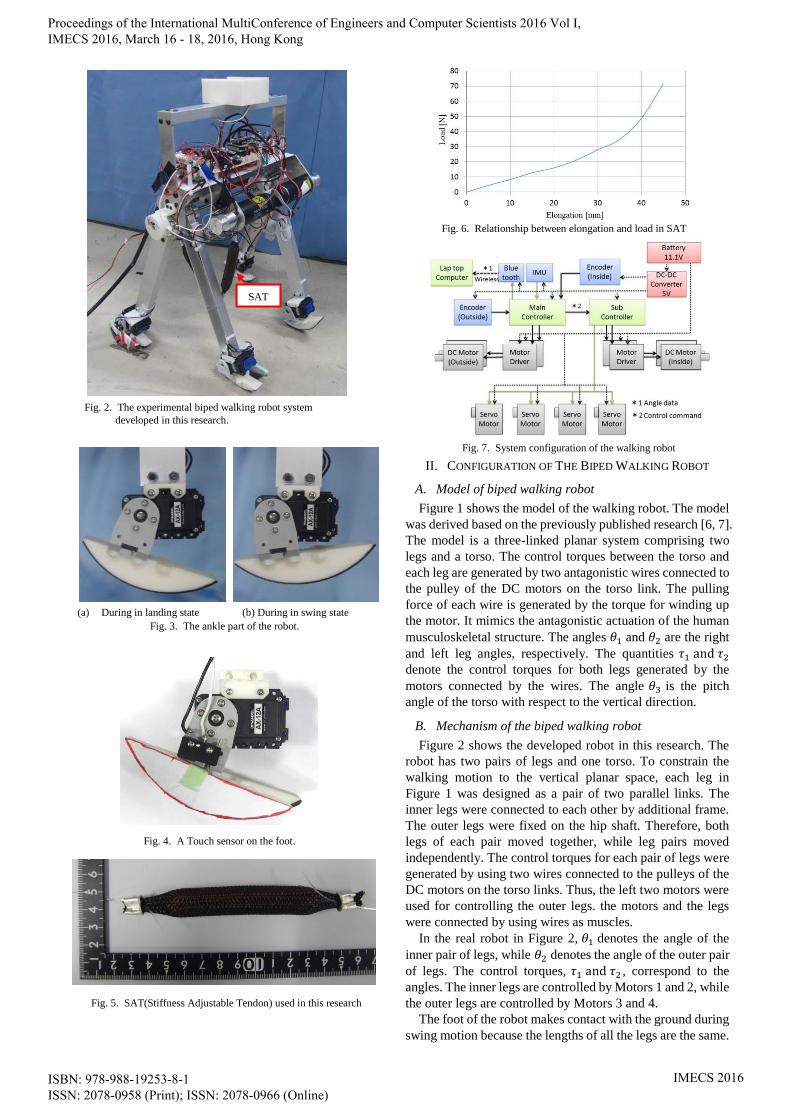
C. Non-Linear Spring SAT
Human walking shows high adaptability against
disturbance such as external force or unevenness of terrain. It
is realized by adjusting elasticity of leg joints using muscle
antagonism which utilizes the peculiar characteristics of
non-linearity. Non-linear spring is needed to adjust its
elasticity. A non-linear spring of SAT shown in Figure 5 was
employed in this research. Its characteristic of non-linear
spring is shown in Figure 6 which shows relationship
between elongation and load on SAT. It is observed that the
more the SAT stretched, the higher stiffness is achieved.
D. Configuration of control system
The system configuration of the developed robot system is
shown in Figure 7. This robot is controlled by two controllers.
Two encoders were installed at the hip joints to measure the
angles between both the leg pairs and torso. An attitude
sensor (IMU: Inertial Measurement Unit) was installed on the
robot’s torso to measure the angle of the torso. The control
torques were calculated using the main controller cased on
the information from the sensors. For generating the torque of
inner legs, Motors 1 and 2 were controlled by the main
controller. Motors 3 and 4 for outer legs were controlled by
the sub-controller, based on the commands from the main
controller. The servo motors for changing the feet angles
were also controlled by the sub-controller. The internal status,
including the angles of the legs and the torso, was wirelessly
sent to a laptop computer by using a Bluetooth module. The
servo motors and motor drivers were supplied with voltage of
11.1 (V). the controllers, encoders, IMU and Bluetooth
module were supplied with the voltage regulator of 5.0 volts.
III. CONTROL METHOD
A. Control for Walking Motion
The fundamental control scheme for walking motion of
this research is based on semi-passive walking [6], an
extension of passive walking [4, 5]. The robot’s walking
motion is decided in four stages, according to the values of
the touch sensors. The stages are as follows:
(a) The inner legs are in the stance stage and the outer legs
are in the swing phase.
(b) The both legs are in stance stage and 𝜃1 is positive.
(c) The outer legs are in the stance phase and the inner
legs are in the swing phase.
(d) The both legs are in stance stage and 𝜃1 is negative.
Therefore, different control methods are applied according to
these stages, as follows.
In the state (a), the control torques 𝜏1 and 𝜏2 are given as
follows:
−𝜏1 − 𝜏2 = 𝑘3𝑝(𝜃3𝑑 − 𝜃3) (1)
𝜏2 = 𝑘2𝑝(𝜃12𝑑 − 𝜃12) (2)
𝜃12 = 𝜃1 + 𝜃2 (3)
𝜃12𝑑 = 𝜋/2 (4)
Here, 𝜏1 denotes the torque applied to the outer legs, 𝜏2
denotes the torque applied to the inner legs, 𝑘3𝑝 denotes the
proportional gain, 𝜃3𝑑 denotes the desired angle of the torso,
𝜃12𝑑 denotes the desired angle of the outer legs, 𝑘2𝑝 denotes
the proportional gain. In addition, the robot turns the feet of
the inner legs downward and the feet of the outer legs
upward.
In the stage (b), the control torques 𝜏1 and 𝜏2 are
computed by (1) and the following equation:
𝜏1 = 𝑘1𝑝(𝜃12𝑑 − 𝜃12) (5)
Here, 𝑘1𝑝 denotes the proportional gain. In addition, the robot
turns the toes of the inner and outer legs downward.
In the stage (c), the control torques 𝜏1 and 𝜏2 are
computed by (1) and (5). In addition, the robot turns the toes
of the inner legs upward and the feet of the outer legs
downward.
In the stage (d), the control torques 𝜏1 and 𝜏2 are
computed by (1) and (2). In addition, the robot turns the toes
of the inner and outer legs downward.
B. Generating Torques with Antagonistic Actuation
Each leg pair of the robot is controlled by two DC motors
and wires with SAT; thus, the torque of the joints are
generated by the torque of the four motors. They are
computed by the following equations:
𝜏1𝑚 = {𝜏1 − 𝜏𝑝 (𝜏1 < 0)
−𝜏𝑝 (𝜏1 > 0) (9)
𝜏2𝑚 = {𝜏𝑝 (𝜏1 < 0)
𝜏1 + 𝜏𝑝 (𝜏1 > 0) (10)
𝜏3𝑚 = {𝜏2 − 𝜏𝑝 (𝜏2 < 0)
−𝜏𝑝 (𝜏2 > 0) (11)
𝜏4𝑚 = {𝜏𝑝 (𝜏2 < 0)
𝜏2 + 𝜏𝑝 (𝜏2 > 0) (12)
Here, 𝜏𝑝 is a preload torque for preventing wires from
sagging and for changing the internal force in the antagonistic
actuation.
Fig.8. Experimental environment
Proceedings of the International MultiConference of Engineers and Computer Scientists 2016 Vol I, IMECS 2016, March 16 - 18, 2016, Hong Kong
ISBN: 978-988-19253-8-1 ISSN: 2078-0958 (Print); ISSN: 2078-0966 (Online)
IMECS 2016

Fig. 10. Temporal dynamics of the joints’ angles for the robot walking with P control.
(a) t = 0.46 [s] (b) t=0.60[s] (c) t=0.66[s] (d) t=0.70[s]
(e) t =0.73 [s] (f) t=0.76[s] (g) t=0.83[s] (h) t=0.90[s]
(i) t = 0.93[s] (j) t=1.00[s] (k) t=1.06[s] (l) t=1.16[s] Fig. 9. Experimental result of the robot walking.
Proceedings of the International MultiConference of Engineers and Computer Scientists 2016 Vol I, IMECS 2016, March 16 - 18, 2016, Hong Kong
ISBN: 978-988-19253-8-1 ISSN: 2078-0958 (Print); ISSN: 2078-0966 (Online)
IMECS 2016

IV. WALKING EXPERIMENT
The developed robot system with the proposed method
had been validated by performing a walking experiment on a
horizontal surface.
A. Experimental Environment
Figure 8 shows the environment of the walking experiment.
This experiment was conducted on a horizontal surface. A
linear frame and a belt connecting the robot to the bar were
used for safety of the robot system. This configuration did not
affect the walking motion. However, when the robot fell
down owing to a walking motion failure, the robot was hung
on the bar with a belt; thus, the configuration prevented the
robot from collapsing on the ground.
B. Experimental Result
Figure 9 shows experimental result. The figures, from (a)
to (l) in Figure 9, show the snapshot captured while the robot
had been walking on the ground in the experiment. Figure 10
shows the time history responses of the angles of both legs
and the torso. The robot landed 4 times in this experiment.
V. CONCLUSION
In this research, the semi-passive biped walking robot with
antagonistic actuation using non-linear spring was developed.
The walking experiment was carried out by using the control
method proposed in this research. Resultantly, it was shown
in the experiment where the developed robot with
antagonistic actuation can walk on the horizontal ground.
Furthermore, it was observed that its capability is similar to
that of the previous research with no non-linear spring [13].
For more effective and stable walking motion, it is needed
to utilize the control method that can adjust the elasticity of
the joint as proposed previous research [11].
REFERENCES
[1] Y. Sakagami, R. Watanabe, C. Aoyama, S. Matsunaga, N. Higaki, and
K. Fujimura, “The intelligent ASIMO: System Overview and Integration”, Proc. of the Int. Conf. on Intelligent Robots and Systems,
3, pp2478-2483, 2002.
[2] K. Kaneko, F. Kanehiro, M. Morisawa, K. Akashi, G. Miyamori, A. Hayashi and N. Kanehira, “Humanoid Robot HRP-4 - Humanoid
Robotics Platform with Lightweight and Slim Body –,“ IROS,
pp.4400-4407, 2011. [3] K. Ono and R. Liu, “Optimal Biped Walking Locomotion Solved by
Trajectory Planning Method”, J. of Dynamic Systems., 124,
pp.554-565, 2002.
[4] T. McGeer, “Passive dynamic walking”, Int. J. Robot. Res., 9, 2,
pp.62-82, 1990.
[5] K. Rushdi, D. Koop and C. Q. Wu, “Experimental studies on passive dynamic bipedal walking”, Robotics and Autonomous Systems, 62,
pp.446-455, 2014.
[6] H. Koike, J.H. Lee and S. Okamoto, “Development and motion control of a biped walking robot based on passive walking theory”, Artificial
Life and Robotics, 19, pp. 68-75, 2014.
[7] H. Yamada, J.H. Lee and S. Okamoto, “Semi-passive Biped Robot using Motion Control Combining Energy and PD Controls,”
Proceeding of the IMCES, pp.297-300, 2014.
[8] B. Vanderborght, B. Verrelst, R. V. Ham, M. V. Damme, P. Beyl and D. Lefeber, “Development of a Compliance Controller to Reduce Energy
Consumption for Bipedal Robots,” Autonomous Robots, 24,
pp.419-434, 2008. [9] K. Hosoda, T. Takuma, A. Nakamoto and S. Hayashi, “Biped robot
design powered by antagonistic pneumatic actuators for multi-modal locomotion,” Robotics and Autonomoous Systems, 56, pp.46-53,
2007.
[10] R. Niiyama, S. Nishikawa and Y. Kuniyoshi, “Athlete robot with
applied human muscle activation patterns for bipedal runnning,” Humanoid Robots, pp.498-503, 2010.
[11] T. Yano, J.H. Lee and S. Okamoto, “Development of 1-DOF Leg
System with Musculoskeletal Structure,” ROBOMEC, 2015. [12] H. Takemoto, J.H. Lee and S. Okamoto, “Control Experiment of
1-DOF Actuation Unit with Musculoskeletal System,” JSME
Chugokushikoku gakuseikai 45th gakuseiin sotsugyokenkyu koenkai, 2015.
[13] T. Yano, J.H. Lee and S. Okamoto, “Development of Biped Walking
Robot with Antagonistic Actuation” International Conference on Mechatronics and Manufacturing, 2016.
[14] T. Shirai, T. Hirose and T. Tomioka, “Development of a Three-Link
Robot by using Non-Linear Spring SAT,” ROBOMEC, 2006.
Proceedings of the International MultiConference of Engineers and Computer Scientists 2016 Vol I, IMECS 2016, March 16 - 18, 2016, Hong Kong
ISBN: 978-988-19253-8-1 ISSN: 2078-0958 (Print); ISSN: 2078-0966 (Online)
IMECS 2016