
Waikie-Talkies How to Make - worldradiohistory.com · HOW TO MAKE WALKIE-TALKIES by F. G. RAYER,...
58
How to Make Waikie-Talkies F.G. RAYER, T.Eng.(CEI),'Assoc.IERE, G3OGR
Transcript of Waikie-Talkies How to Make - worldradiohistory.com · HOW TO MAKE WALKIE-TALKIES by F. G. RAYER,...
How to MakeWaikie-Talkies
F.G. RAYER, T.Eng.(CEI),'Assoc.IERE, G3OGR
1
HOW TO MAKE WALKIE-TALKIES
ALSO BY THE SAME AUTHOR
No. BP30 Two Transistor Electronic ProjectsNo. BP32 How to Build Your Own Metal and Treasure
LocatorsNo. BP35 Handbook of IC Audio Preamplifier and Power
Amplifier ConstructionNo. BP37 50 Projects Using Relays SCR's & TriacsNo. BP39 50(FET) Field Effect Transistor ProjectsNo. BP48 Electronic Projects for BeginnersNo. BP57 How to Build Your Own Solid State Oscilloscope
HOW TO MAKE WALKIE-TALKIES
by
F. G. RAYER, T.Eng.(CEI), Assoc.IERE, G3OGR
BABANI PRESSThe Publishing Division of
Babani Trading and Finance Co. LtdThe Grampians
Shepherds Bush RoadLondon W6 7NF
England
Although every care is taken with the preparation of this book, thepublishers or author will not be responsible in any way for any errorsthat might occur.
© 1977 BABANI PRESS
I.S.B.N. 0 85934 046 5
First Published - December 1977Reprinted - July 1979
Printed and Manufactured in Great Britain byC. Nicholls & Co. Ltd.
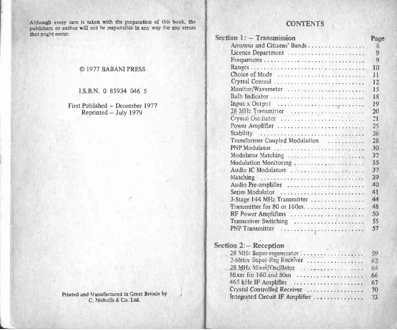
CONTENTS
Section 1: - Transmission PageAmateur and Citizens' Bands 8
Licence Department 9
Frequencies 9
Ranges 10Choice of Mode 11
Crystal Control 12
Monitor/Wavemeter 15Bulb Indicator 18
Input x Output 1928 MHz Transmitter 20Crystal °sell a t or 21
Power Amplifier 25Stability 26Transformer Coupled Modulation 28PNP Modulator 30Modulator Matching 32Modulation Monitoring 35Audio IC Modulators 37Matching 39Audio Pre -amplifier 40Series Modulator 413 -Stage 144 MHz Transmitter 44Transmitter for 80 or 160m 48RF Power Amplifiers 50Transceiver Switching 55PNP Transmitter 57
Section 2:- Reception28 MHz super -regenerator 592 -Metre Super -Reg Receiver 6228 MHz MixeilOscillator 64Mixer for 160 and 80in 66465 kHz IF Amplifier 67Crystal Controlled Receiver 70integrated Circuit IF Amplifier 73
Page2 -Stage Audio Amplifier 75Receiver Audio IC 76Superhet for 2m 77FM 86
Section 3:- Aerials and Additional CircuitInformation
Aerials 87144 MHz Verticals 90Pi Tank 93Capacitor Loading 96Further Circuits 96Simple Talkie 97Super -regeneration 99Carbon Microphone 100Stabilisation 101RF Blocking 10227 MHz Citizens' Band Operation 103
SECTION 1
TransmissionEquipment for low power hand-held or portable operationneed not be of a very complicated type. It falls much morereadily within the scope of the home constructor than doesmedium and high powered transmitters, and multi -bandreceivers for the Amateur frequencies. There are severalreasons for this simplification. The equipment will be for asingle band, instead of for multi -band use, and this alonegreatly reduces the number of components necessary.
Another saving naturally arises from the relatively low poweremployed for transmission. This considerably reduces thenumber and size of components and eases constructionalwork.
Again, with an Amateur band transmitter or transceiver(transmitter -receiver) the present-day trend is to use singlesideband transmission. This offers maximum utilisation ofpower for voice transmission, but requires a balancedmodulator and filter to remove the unwanted carrier andsideband. As these items themselves form a large part of asingle sideband transmitter, they are not justified in lowpowei equipment. As a result, amplitude modulation isgeneral in these circumstances, and the generation of anAM signal needs very few components and circuitry,compared with the production of SSB signals.
In addition to these points, the practical needs of low powercommunication are often met by the use of only one or twopre-set frequency channels. This, in turn, brings moresimplification, when adopted instead of the variable-frequencyoscillator means of transmitter control.
Transmission and reception may take place on crystal control-led frequencies, and then there need be virtually no adjust-ments at all during use. Two transceivers of this type, builtfor use together, act as a familiar walkie-talkie link.

On the other hand, Amateurs have long found interest inlightweight portable operation, and fully tunable equipmentis then of enormously greater scope. With it, other Amateurstations at considerable distances can be worked, especiallywhen the other station is using medium or high power trans-mission, with a full aerial -earth system and sensitive receiver.In fact, portable or temporary location working forms a largepart of the activity of some Amateurs, especially duringsummer months.
Amateurs will be familiar with the operation of "talk in"stations at rallies, with "fox hunting" (location of a hiddentransmitter by directional means) and similar activities.These can easily be added to the more direct point-to-pointcontact afforded by a set of transceivers. In fact a singletransceiver will in some cases be all that will be required, asit can provide two-way contact via the usual home stationwith its permanent transmitter and receiver.
It has been found in practice that "portable" operationcovers a larger field than might be anticipated. Items whichhave been constructed and used for portable operation, orfor activities in conjunction with portable equipment, includethe following:
Lightweight pocket transceivers for relatively short point-to-point ranges; tunable pocket equipment for reception only,so that the enthusiast with no transmitting licence canparticipate as a listener; larger power equipment, easily trans-portable, for use as a base station in caravan, tent, or whenon holiday etc. There are in fact those devoted largely or evenwholly to {RP (low -power) working, and thus the circuitsdescribed could fall within their scope.
Amateur and Citizens' BandsEquipment is intended for licensed operation, so will generallybe used in one of the permitted Amateur frequency bands.One such allocation - the 28 MHz band - falls very near thepopular USA Citizens' Band, where operation is around
8
27 MHz. Citizens' Band equipment working on 27 MHz can-not obtain a licence in Great Britain, but such equipment canin some circumstances be shifted into the permitted 28 MHzband used by Amateurs. In a similar manner, the circuitsshown for 28 MHz can be set up to work in the 27 MHz Band,where this is permitted, and details for this are included.
In Great Britain, passing a test which includes Morse allowsoperation in all the Amateur bands, while if Morse is notattempted only very high frequency bands may be employed.This may have an important bearing on the workingfrequencies chosen.
Unlicensed operators are generally termed "pirates" and whentheir illegal operation is detected they should at least expectthe GPO to confiscate their equipment. Receiver circuits inthis book may be used by anyone, but transmitting circuitsshould only be operated by holders of a suitable licence.
Licence DepartmentThe transmitting circuits described here are intended for use inthe permitted Amateur bands, and an Amateur transmittinglicence is required for the operation of such equipment.Details of the licences available for the use of transmittingequipment in Great Britain may be obtained from:
Home Office,Radio Regulatory Department,Waterloo Bridge House,Waterloo Road,London, SE1 8UA.
No special licence is necessary for the use of receiving circuitssuch as those included, or for reception of Amateur signals.
FrequenciesLicence conditions at present allow the use of the followingfrequency bands: 1.8-2.0 MHz, 3.5-3.8 MHz, 7.0-7.1 MHz,14.0-14.35 MHz, 21.0-21.45 MHz, 28.0-29.7 MHz, 70.025-70.7 MHz, 144-146 MHz, 420-450 MHz, and various
9

extremely high frequencies. It is worth while referring tothese individually.
The 1.8 MHz or 160 metre band has considerable use for lowpower Amateur activity, especially as transmitter power onthis band is limited to 10 watts. This band would generally beexpected to give contacts up to 25 miles or so, though natural-ly greater ranges are often covered. For present purposes, the3.5 MHz or 80 metre band is somewhat similar, though greaterranges are covered. The band can be very noisy during eveningor darkness hours. Either of these low frequency bands cangive reliable short distance ground wave communicationexcept when conditions are unfavourable.
The 7 MHz (40 m), 14 MHz (20 m) and 21 MHz (15 m) bandsare generally used for very long distance communication, andare not of advantage here.
The 28 MHz or 10 metre band has little interference from verydistant signals except during certain favourable conditions, andis popular for purposes such as those in view, being similar incharacter to the 27 MHz band.
The 70 MHz or 4 metre band has advantages for short rangelow power working, but the 144 MHz or 2 metre band is moreused, and is popular with VHF operators. The 420 MHz andhigher frequency bands are not very popular at present, dueto device and other limitations.
Equipment can thus generally best be for the low frequencybands 160 m or 80 m; or for 10 m; or for 2 m. This doesnot of course completely rule out the other bands, whichhave their own advantages in some circumstances.
RangesReliable contact is by ground wave, which falls away instrength as distance increases. Contact may also behindered by hills or other obstacles in the signal path.Propagation conditions being equal, range is increased byraising the transmitter power, by increasing the receiver
sensitivity, or by using more efficient aerials with trans-mitter or receiver.
Greater ranges are obtained by a sky wave reflected fromionized layers above the earth. These layers suffer hourlyand seasonal variation. As a result, strong communicationby sky wave may be possible at one particular time, forsome days, but may then cease or suffer fading and otherdefects. These effects permit very long distance contacts,but not essentially reliable communication. Effects of thiskind arise with all high frequency signals, at other thanground wave distances. They will be faimilar to all wholisten to short wave broadcast or Amateur transmissions.
Choice of ModeIn view of the high efficiency and low voice duty cycle ofthe single sideband transmitter, this mode would be ideal forlow power working. Unfortunately, the generation of anySSB signal poses considerable problems because of thecircuitry necessary. The same filter and other items willbe necessary for low power, as for high power SSB, andthe equipment becomes costly and much less compact.
Frequency modulation on the VHF bands has some advan-tages, but can cause extra complication in the receiver, ormake the use of a simple type of receiver impossible. FMthus becomes something of a luxury, in home built light-weight equipment (See FM page 86).
For voice transmission, amplitude modulation or AM thushas to be adopted in most cases. There is a loss over SSBas power is used to generate a carrier and two sidebands,but equipment is very much easier to construct, and issmaller and much less costly.
Some low power enthusiasts use CW (Morse) in order towork great distances with portable equipment. Ranges ofthousands of miles are possible with milliwatts of powerand such equipment may be carried to elevated locations.
10 11

Such expeditions by the Dx (long distance communication)enthusiast rely on high frequency band skip. For groundwave or 144 MHz working, power of perhaps 200 milliwatts(0.2 watt) would be more appropriate for a few miles,using AM. Range does of course depend enormously onthe aerial, and the ranges obtained with efficient aerials cangreatly exceed those when short whip aerials are in use.(Reference should be made to the information on propagationand aerials.)
Crystal ControlThe use of crystal control of frequency means that circuits aresimplified, and it is not necessary to keep to hand equipmentwhich can verify the frequency. When correctly built, thecrystal controlled circuit can only operate at the frequencyof the crystal, and this is rigidly maintained. Drift due tochanges in battery voltage or temperature , or randomvariations from mechanical vibration, are avoided.
A single crystal will provide one operating frequency only,but this limitation is not too important. Where it is wished towork other fixed location stations the latter will normallyfully tunable equipment, so can readily shift to the crystalfrequency. For two or more channels, it is necessary to usemore crystals, which can be selected by switching.
The transmitter can often use the stages shown at A inFigure 1. The crystal controlled oscillator works at thefrequency of the signal to be transmitted. It is followed bya power amplifier (PA), to boost the transmitted power. Theaudio section has a preamplifier, followed by a stage whichmodulates the PA, and thus the transmitted signal.
For VHF working it will become necessary to multiply thecrystal oscillator frequency, as at B. As example, a 72 MHzoscillator, followed by a doubler, would give 144 MHz opera-tion. An extra stage is then required.
CRYSTAL CONTROLLEDOSCILLATOR
AUDIOPREAMPLIFIER
O
O
POWERAMPLIFIER
M MODULATOR
CRYSTALCONTROLLEDOSCILLATOR
-11 MULTIPLIERDRIVER PA
FIG. I. MODULATOR --I
With some circuits modulation is also applied to the stagewhich precedes the PA, as by this means greater depth ofmodulation can be achieved.
For minimum size and low power, the arrangement at A willbe most used, and is satisfactory on 1.8 MHz to 28 MHzbands. On some occasions oscillator, driver and PA stages allwork on the same frequency, as more power can then be madeavailable. This is practicable, but greater freedom frominstability or similar troubles will be expected when theoscillator is followed by a multiplier. Again, in some circum-stances it is easy to arrange so that an intermediate stage willoperate either as a multiplier, or straight through, and thustwo -band operation is obtained with a single crystal.
If two hand-held units are to be built to work together, theywill work on the same frequency. If a home base or otherstation tunes up on this frequency, communication can thenbe 3 -way if required.

Where the receiver is tunable, it can of course be adjusted toany signal it is wished to hear. However, for stability a crystalcontrolled receiver oscillator is popular. This will allowreception on one frequency only, so the crystal frequency hasto be chosen to suit the transmitter.
SUPER -REGENERATIVEDETECTOR AF AMP.
MIXER-TUNABLE OSC. IF AMP. DET. &
AF
MIXER
CRYSTALOSCILLATOR
IF AMP.
FIG. 2.
imaimimmi
DET. &AF
Figure 2 will clarify the situation here. At A, a tunable super -regenerative receiver is indicated, and this can be tuned to anywanted frequency. At B, a tunable superhet is shown. Bytuning the oscillator, signals can be received on any wantedfrequency. At C, a crystal controlled oscillator is used. Thisallows reception on one chosen frequency. As example,assume the transmitter operates on 28.5 MHz. The crystalin the receiver oscillator must differ from this by an amountcorresponding to the receiver intermediate frequency. In theexample, and assuming that the receiver IF is 460 kHz, thereceiver oscillator crystal will be either 28.5 MHz plus460 kHz (28.960 MHz) or 28.5 MHz less 460 kHz (28.040MHz). Only when the crystal frequencies differ by the IF isreception possible. For this system, crystals can be purchasedin pairs. The rigid control of both transmitter and receiveroscillators means that tuning is correctly maintained.
14
Crystal control of the receiver has the advantage that driftfrom the wanted frequency does not arise. However, thelower cost and greater scope of a tunable receiver can give itsome advantage. It is also feasible to use the super -regenerative type of tuned receiver which has excellentsensitivity, and is much easier to build than a superhet.
It will thus be seen that crystal control of the transmitter isgeneral for equipment of the type in view. For a 2 -stationlink to be used for no other purpose, crystal control of thereceiver is also recommended. But for simplicity in buildingand greater utility for other purposes, the receiver can betunable.
A transceiver, or combined transmitter -receiver, could be madeby using one circuit from Figure 1 and one from Figure 2.This has some advantages from the constructional viewpoint,as receiver and transmitter sections are separate, so can bebuilt and tested individually. As an alternative to this, circuitscan employ some stages in both transmission and reception.The audio section is most commonly used in this way, actingas modulator on transmission, and receiver audio amplifierfor reception. This can reduce the number of components,and size of the equipment, but generally requires morecomplicated switching to change from transmit to receive.
Monitor/WavemeterA combined monitor and wavemeter is very easily constructedfor the wanted band, and will prove extremely useful whentesting and setting up a transmitter circuit. It will show thatradio frequency energy is being produced in oscillator oramplifier stages, and also give an indication of signal strength,as an aid to tuning oscillator or other circuits. By plugging inheadphones, it will enable the radiated signal to be checked forspeech quality or modulation. With an aerial added, it canhelp in tuning a transmitter for best radiated signal strength.
Figure 3 is the circuit of this unit. RF energy is picked up byLl and rectified by DI. This provides an indication on themeter. The jack socket must be of a type which shorts when
15
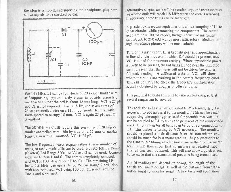
the plug is removed, and inserting the headphone plug hereallows signals to be checked by ear.
For 144 MHz, LI can he four turns of 20 swg or similar wire,self-supporting, approximately 9 mm in outside diameter,and spaced so that the coil is about 18 mm long. VC1 is 25 pand Cl is not required. For 70 MHz, use seven turns of26 swg enamelled wire on a 11 minor similar former, withturns spaced to occupy 15 mm. VC1 is again 25 pF, and Clis omitted.
The 28 MHz band will require thirteen turns of 28 swg orsimilar enamelled wire, side by side on a 11 mm or similarfomer, also with CI omitted. VC1 is 25 pF.
The low frequency bands require rather a large number ofturns, so ready-made coils can be used. For 3.5 MHz, a Denco(Clacton) Ltd Range 3 Yellow Valve coil can be used. Conneetions are to pins 1 and 6. The core is completely removed,and VC1 is 100 pF with 22 pF for Cl. The remaining LFband, 1.8 MHz, can use a Denco Yellow Range 2 coil, alsowith core removed, VC1 being 100 pF. Cl is not required.Pins I and 6 are used.
Alternative surplus coils will be satisfactory, and most mediumwaveband coils will reach 1.8 MHz when the core is removed.If necessary, some turns can be taken off.
A plastic box is recommended, as this allows coupling of LI toother circuits, while protecting the components. The meterneed not be a 100 pA model, though a sensitive instrument(say 50 pA to 250µA) will be most satisfactory. Medium orhigh impedance phones will be most suitable.
To use this instrument, LI is brought near and approximatelyin line with the inductor in which RF should be present, andVC1 is tuned for maximum reading. Where appreciable poweris likely to be present, do not bring Ll too near the inductoruntil it is seen that the meter will not be driven beyond itsfull-scale reading. A calibrated scale on VC1 will showwhether circuits are working in the correct frequency band.This can be useful to check the frequency multiplicationactually obtained by doubler or other circuits.
It is practical to build this unit to take plug-in coils, so thatseveral ranges can be covered.
To check the field strength obtained from a transmitter, it isnecessary to add an aerial to the monitor. This can be a self-supporting telescopic type as used for portable receivers. Itcan be coupled to LI by using the primaries of the ready-madecoils. Or coupling for all bands can be by direct connection toLI. This makes re -tuning by VC1 necessary. The monitorshould be placed a little distance from the transmitter, andshould be tuned for best meter reading. Any adjustments tothe transmitter tuning which cause a rise in the monitor meterreading will then show that an increase in radiated fieldstrength has been obtained. This will also allow a quick checkto be made that the accustomed power is being transmitted.
Actual readings will depend on power, the length of theaerials and surroundings, as well as the distance from trans-mitter aerial to monitor aerial. A few tests will soon show
16 17

what to expect. Should communication become unsatisfac-tory and transmitter power fall off, a check of the transmitteror its batteries would be in order. But should transmitteroutput be as usual, investigation of the receiver would beindicated.
CI22 PF
LI
RI 2.2Mn-C73-
I II C3 0.1).,F
' C 2IVCI IONF
FIG. 4.
3/9V
T R I
Figure 4 is a similar circuit, but it provides boosted phonereception for monitoring signals. Medium or high impedancephones of about 500 to 2,000 ohm will be most suitable. TRcan be a BC108 or any small audio NPN transistor.
Bulb IndicatorA bulb can be extremely useful to show that a transmittercircuit is giving the expected power output. Radio frequencyenergy is allowed to flow through the bulb, or is supplied tothe bulb instead of the aerial. The bulb will then light inaccordance with the RF energy present.
For oscillators and low powered circuits, a 6 volt 0.06A 0160 mA bulb is suitable. When fully lit, this will be of about100 ohm impedance, and will show that about 360 mW of
18
RF can be obtained. The 6 V 0.1 A bulb will be of approxi-mately 60 ohm impedance when lit, and will show 600 mWor 0.6 W of RF.
Larger bulbs will only be required for larger power. Thus a6.3 V 0.15 A bulb will be a little over 40 ohm, and require950 mW, while a 6.3 V 0.3 A bulb will be a little over 20ohm and need 1.8 W. As the impedance becomes too low,higher voltage bulbs are necessary for higher power, or bulbsin series. Thus a 12 V 2 W bulb would be of about 70 ohmimpedance when lit.
Such lamps are available from garages, cycle shops, etc. Theusual torch bulb, such as 3.5 V 0.3 A is of too low impedance(near 10 ohm) to act as a substitute for an aerial but can insome instances be in series with an aerial to indicate radiofrequency current.
Generally, only an indication that the transmitter is workingas it should will be required. For RF output measurements,a thermo-couple or other RF meter is needed, with a suitablenon -inductive load. 12 xR (current x current x resistance) willthen show RF power. It should be noted that as current issquared power rises rapidly. Thus a current of 0.1 A through100 ohm would indicate 1 watt, while a current of 0.2 Awould show 4 watts
Efficiency in radio frequency power output stages is not verylikely to be over 66 per cent, and may well be less. Input toan RF power amplifier is V x I, and output can be found as justexplained. Lost power is mostly dissipated in the outputtransistor as heat. Thus incorrect tuning, as example, cancause poor RF output, and also overheating of the amplifier.This can set a limit on the direct current power input whichcan be allowed, if destruction of the transistor is to beavoided.
Input x OutputAs an example, assume the power amplifier were drawingabout 80-90 mA with a 12 V supply, so that its DC input is
19

about 1 watt. If output lights a 600 mW lamp efficiency isabout 60 per cent, and the remaining 400 mW will be lost andheat transistor. Working would be safe if the transistorcould dissipate 400 mW or over, so a 500 mW device wouldbe suitable. But if incorrect tuning reduced output to, say,300 mW, then about 700 mW would be dissipated in thetransistor, causing overheating.
Except for very low power circuits, it may thus be wiser tomake a first test with a reduced voltage, so that tuning can beadjusted. Should an amplifier transistor become hot, it iswise to switch off or reduce voltage until working conditionshave been checked.
28 MHz TransmitterWorking on 28 MHz gives similar conditions to those whichapply to signals on the 27 MHz Citizens' Band. Many ofthe adjustments which are required for a 28 MHz transmitterwill be similar to those which are necessary for other fre-quency bands. It is thus worth while to consider the tuningup of a transmitter for low power use on 28 MHz in somedetail.
Some well-known 27 MHz equipment of overseas manufactureoperates with a power of about 200 mW. The transmitter hercan be run with a power input of up to about 500 mW. Thisoffers some increase in signal power, without becoming toocostly in terms of battery current. It is quite feasible toreduce power by lowering the battery voltage, or by tuningin such a way that less drive is applied to the final RFamplifier.
The whole transmitter consists of crystal oscillator, RF poweramplifier, and modulator. To avoid expensive batteries, itcan be run from six 1.5 V cells, or an ordinary 9 V battery.(For lengthy use, rechargeable cells would eventually provemore economical.)
The transmitter may be completed before applying power antesting it, and may well need no further attention except for
20
tuning. However, a detailed check of the working of eachstage can be made as described, either as work progresses, orto trace snags.
Crystal OscillatorFigure 5 is the circuit of a typical crystal controlled oscillatorhere intended for the 28 MHz band. The crystal indicated isfor 28.5 MHz, but naturally other frequencies can be usedinstead.
LI is tuned to approximately the frequency of the crystal,by means of its adjustable core. The exact diameter of theformer, or wire gauge, will not be important, but the typeof core must be suitable for HF use (up to 30 MHz orhigher). With a former of approximately 7 mm diameter,LI can be fifteen turns of 26 swg enamelled wire side byside. For a slightly smaller coil, seventeen turns of 32 swgwire can be used on a 5 mm former. In each case L2 isfour turns, tightly coupled to Ll.
When making coils of this type, turns can be kept in placeby spots of adhesive at each end of the winding. However,the whole winding should not be secured with varnish, wax,
21

or similar substances which will cause losses. "Bostik 1" issuitable, applied sparingly.
When adding L2, it may be noted that if coupling to LI isvery loose, the RF output available will be reduced. On theother hand, if coupling is very tight, the oscillator may notfunction. Best coupling will give a good transfer of RFenergy, without stopping oscillation.
Many transistors will perform well in this circuit, and theBC109 or 2N2221A may be adopted. Cl is best a silver micaor other component suitable for HF. Resistor values shownwill usually prove to be satisfactory, though they can bemodified somewhat for other transistors.
When Ll is badly off resonance, no oscillation is obtained.The presence of RF can be, found by bringing the wavemetercoil near to LI, and tuning the core for maximum deflectionof the meter. Or temporarily connect L2 to a 6 V 0.06 Abulb. With the oscillator tuned for a dip of about 10 mA to15 mA, sufficient RF should be obtained to light this bulbdimly. That is, at about similar brilliance to that seen ifthe bulb is connected to a 1.5 V or single cell battery.
It will be found that LI has to be tuned slightly away fromthe setting which gives maximum possible brilliance, or theoscillator will not start again, if the battery circuit isinterrupted, then restored. This is usual with crystal con-trolled oscillators of this kind. Correct tuning is that givingmaximum output, with reliable starting.
With compact commercial and home -built equipment of thistype, the number of stages are minimised. It is thus importantto get the best RF output from the oscillator, or there will beinsufficient drive to the following amplifier, and the transmit-ter output will be poor.
The supply need not be 9 V, and 12 V would increase output.It is of advantage to get the best efficiency from each stage,for good range without unnecessary battery power.
For small changes in frequency, such as result from alternativecrystals, re -tuning of LI will generally be unnecessary. Finaltuning is approximately correct when carried out as explained,but when L2 is driving the following amplifier some smallreadjustment of the core of Ll will be required for maximumefficiency.
RI E R3
1.
(R4 leC2
C3f.
.1.111/1, 41=sio,....................CI
+
B
CTR 1/2
FIG .6.
A.
Figure 6 shows the assembly of this stage. If 0.15 in matrixperforated board is used, components can be placed exactlyas indicated. Some further reduction in size would bepossible, but if dimensions are reduced to the absolute
2? 23

minimum constructional work becomes cramped and
difficult.
The coil former is approximately 5 mm in diameter and15 mm long. Start at point 1, near the top of the former, and
wind on seventeen turns of 32 swg enamelled wire closely side
by side, finishing at 2. Begin at lead 3, winding four turns inthe same direction as Ll, and ending at 4. Push these turnsagainst Ll. Secure the wires as described. The position of thecoil core is approximately as shown though this will differ
slightly with individual coils and wiring. Note the core ispositioned for maximum coupling from Ll to L2, not outof Ll at the top.
Cl is a small silver mica capacitor, and C2 and C3 are low
voltage disc ceramics. R2 goes flat under the board. Aminiature crystal with holder is used, but wire -ended
crystals can be soldered directly into circuit. The metal
case of TR1 must not touch wires or other bare metal items.
This stage can be tested as described. If a meter is placedin one battery lead, current will dip as tuning of Ll becomescorrect and RF is delivered to L2.
R4 R5100.
C416 PF
TR2
FIG.7
C5 20NF
L3
WY CBFY 51
2N3553
24
Power AmplifierThe circuit for the PA stage is shown in Figure 7 Thecoupling winding L2 supplies RF drive to the base of TR2.With this method, TR2 ceases to operate if drive is absent,and collector current is nearly zero. Final tuning of theoscillator can thus be for maximum collector cuiltn, forTR2, provided the crystal starts when the circuit is switchedon, as described.
Output from TR2 collector is to the centre -tapped coil L3,with parallel capacitor C4. L4 provides coupling to the aerial.
Numerous transistors will give good results with this circuit.The BFY51 is inexpensive and has a minimum fT (frequency)of 50 MHz. The 2N3553 has a higher II' and is a little moreefficient. The small type of transistor as used in the oscillatorstage can also give a good account of itself here. A finned clipon heat sink is required.
The indicating wavemeter will show if RF is present in L3, andtuning can be for maximum indication, and maximum brilli-ance of a 6 V 0.06 A bulb temporarily connected to L4. Thisshould light quite brightly, with TR2 drawing about 40 mA.Only slight readjustment of tuning should be needed, whenthe bulb is disconnected and the aerial is in use.
Damage to TR2 is unlikely. It may arise when current inputto TR2 is high, but RF output obtained is low, due toseverely wrong tuning of L3. In these circumstances,virtually all the power flowing to TR2 is dissipated as heat.The larger type of transistor (BFY51) has a safe dissipationof 800 mW, so this is a safeguard, but the smaller typedissipation is around 300 mW, and these can in unfavourableconditions grow very hot here. Extra care is necessary if a12 V supply is used, and current should be checked with ameter. or the circuit should be adjusted with a 9 V supplyin advance. -
With reasonable care, and with low voltage, it is not likelythat any damage will be caused to TR2 during tuning -up.
25

Figure 6 shows the wiring layout for this stage. This gives
a little separation between LI and L3, as feedback can causeoscillation at frequencies not determined by the crystal.Coupling is reduced by placing the coils at right angles toeach other. The layout could be a little more compact if
a small can were used to screen L1. If the crystal istemporarily removed from its holder, RF output must cease,and battery current drop to a low level.
L3 is eighteen turns of 32 swg enamelled wire, side by side
on a 5 mm cored former. The centre tap is scraped andtinned during winding. A single layer of paper or thin tapeis put over L3, and L4 is wound on this, and has two turns
each side the centre tap of L3. It is possible to raise the
DC input to TR2 by providing greater aerial loading,increasing L4 to six turns. Optimum coupling does in factdepend somewhat on the actual transistor, as well as the
battery voltage. Initially, the four turns can be used for
the transistor types mentioned.
Built in this way, the oscillator and PA circuitry will need
a board about 50 x 20 mm or 2 x s in. This is compact,without going for the minimum size obtainable.
StabilityThe likelihood of instability in the transmitter section of a
transceiver depends on many factors. Difficulty of thiskind may in some cases be introduced inadvertently.
It could be felt that using transistor holders would allow easychanging of transistor types, but holders are only generallypossible in low frequency circuits. In VHF circuits inparticular the extra capacitance and lead length can causeinstability. (This is not so with some receiver circuits such as
the super -regenerative detector, where collector -emitter feed-
back is needed.) Long transistor leads may also result in a
circuit being unsatisfactory. In fact, even a 465 kHz IFamplifier which is unstable may need nothing more thanshortening of base and collector leads, and stray feedbackbecomes more important as frequency rises.
26
There is a trend to the use of transistors with a typical fTof hundreds of MHz and circuits with these are more likelyto have VHF parasitics, than when transistors of lower fT arefitted. A cure may be found in placing a ferrite bead on thebase lead.
The gain of individual transistors varies, and in some casessubstituting one transistor for another of the same type mayresult in instability. In such cases a miniature, low -valueresistor in the base connection at the transistor (or sometimesthe collector) will probably stabilise the circuit.
In VHF circuits in particular by-pass capacitors need to havethe shortest practical lead length to avoid unwanted resonanteffects. High value and low value capacitors in parallel may beneeded to provide effective by-passing at both low and highfrequencies. Capacitors in VHF circuits need to be compon-ents intended for such purposes, such as miniature disc.
Chances of instability develop as the power level rises andmore stages are fitted using the same frequency. Oscillatorand power amplifier, or oscillator, driver and power amplifiercircuits need to be segregated both mechanically and electrical-ly, when all working on the same frequency. Mechanicalseparation will allow screening between stages, while decoupl-ing of the power line will prevent RF passing back from thepower amplifier to the driver or oscillator. Circuits of theoscillator -PA, or oscillator -driver -PA type, with stages whichfollow the oscillator only operating when driven, should beabsolutely "dead" in terms of RF, when the oscillator istemporarily put out of action.
Transistor damage can easily arise if a PA is operated with noload, or with a badly mismatched load. The PA may also beperfectly stable when working into a normal load, but unstablewhen the load is not present, so the latter does not necessarilyindicate any fault.
In general, the circuits in this book will present no particulardifficulty but it is not practical to relax normal precautions
27

such as by using transistor holders or allowing back couplingbetween inductors, without the possibility of trouble arising.Similar care would have to be taken in a receiver where twoor more stages operate on the same frequency.
Transformer Coupled ModulationTo secure full modulation of the power amplifier by changingthe collector voltage, potential at the collector will be swungfrom zero to twice the level present with no modulation. Withthis form of modulation, the instantaneous collector voltagecould thus be expected to reach four times the supply voltage.,Without modulation the collector potential may swing fromzero to twice the supply voltage at radio frequency. Withmodulation applied, the potential to the collector would bedoubled at positive peaks, so that the maximum RF peak istwice this, or four times the supply potential. As a result,the type of modulation which can be used for a PA, or thechoice of the transistor, must allow for this.
Figure 8 shows a transformer coupled modulator, as used in acommercially manufactured transceiver. As this employs PNPtransistors the circuit has a positive ground line.
TR1 is the first audio amplifier and driver, with base bias viaRl/R2, and emitter bias by R3, which has the by-passcapacitor C3. T1 is the driver transformer, with a centre -tapped secondary, to drive TR2/3 in push-pull. R5, R6 andR7 set operating conditions in the output stage. C2 and R4decouple the negative supply line to the first stage.
The speaker unit acts as microphone during transmission, andis switched to TR1 by switch section 1. Cl prevents disturb-ance of DC operating conditions as would arise if the speakerwere directly across R2. Amplified audio signals are thusavailable in the output transformer T2, for transmission.
T2 has two secondaries, S1 and S2. Switch 3 applies thesupply voltage through secondary S2 to the collector circuitof the power amplifier, thus modulating it.
U1
42.12, 4)UI -
4 -
'fib -0(P0_
r -
totY
M 0(N)
so
cci
tL
'00-0Z5`
CV N Cr)
CX co u to
t4CC
W - 1 -
CC
(11U r.\ 11>
WCC i-1
+
2829
For reception, switch section 1 transfers TR1 to the receiver,while 2 connects the speaker to secondary Sl, and switch 3opens to interrupt the PA circuit. The same audio sectioncan thus give speaker reception of signals received.
Except for the switching and T2, these stages are typicalof many portable transistor receivers and amplifiers. Trans-formers such as T2 are not available generally, as they aremade with individual turns ratio for the speaker (secondarySi) and transmitter section power amplifier (secondary S2).However, it is possible to obtain acceptable results bytolerating some mis-match, by resistance loading, or byusing separate transformers or amplifiers.
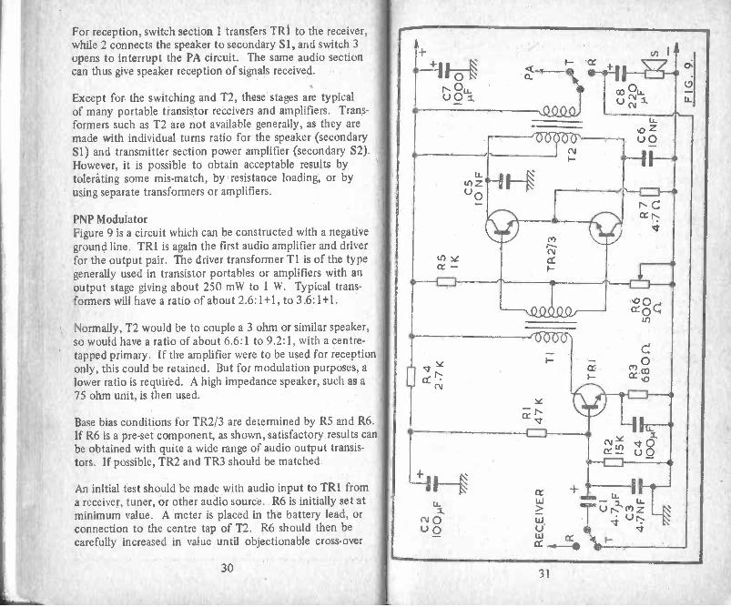
PNP ModulatorFigure 9 is a circuit which can be constructed with a negativeground line. TR1 is again the first audio amplifier and driverfor the output pair. The driver transformer T1 is of the typegenerally used in transistor portables or amplifiers with anoutput stage giving about 250 mW to 1 W. Typical trans-formers will have a ratio of about 2.6: 1+1, to 3.6:1+1.
Normally, T2 would be to couple a 3 ohm or similar speaker,so would have a ratio of about 6.6:1 to 9.2:1, with a centre -tapped primary. If the amplifier were to be used for receptiononly, this could be retained. But for modulation purposes, alower ratio is required. A high impedance speaker, such as a75 ohm unit, is then used.
Base bias conditions for TR2/3 are determined by R5 and R6.If R6 is a pre-set component, as shown, satisfactory results canbe obtained with quite a wide range of audio output transis-tors. If possible, TR2 and TR3 should be matched.
An initial test should be made with audio input to TRI froma receiver, tuner, or other audio source. R6 is initially set atminimum value. A meter is placed in the battery lead, orconnection to the centre tap of T2. R6 should then becarefully increased in value until objectionable cross -over
4)- I F40u) I A
N u.
C';
0U 0 OD IA_"
CV
,Q.S2D
NCcc r.
e -
Necr -0-1 I.
N!)
\QQ.0Q.0, cr 0
I
cvU
1535Z5Z7N
se
en cocr
-ILir)- U0
10-1 1
-
cr .----1 I.... u -LA -> 0 r. el z14 4 'U' 4Lu cc 1-cr -.-
3031

distortion ceases, but current is not over 10 mA or so, withno input. In these circumstances, current peaks at goodvolume will be 40 mA to 60 mA or so. If R6 is of toogreat a value, a large resting or no -signal current will flow
in the output stage.
C3, C5 and C6 are to keep RF out of these circuits, and also
reduce the higher audio frequencies. Reproduction throughthe amplifier should be of acceptable quality. R1, R2 andR3 will suit most audio driver type transistors.
Modulator MatchingThe best ratio for the output transformer T2 is determinedas follows:
Ratio =Optimum load
Speaker impedance
As example, if the best load is 200 ohm, and the speaker isa 3 ohm unit, N/765 = N/66 = 8 (approximately) or 8:1.
An approximation of the modulating impedance of the PAcan be found from V/I. As example, assume the PA draws40 mA to 50 mA from a 9 V supply. This is a load of 225to 180 ohm. So T2 can be approximately 1:1 ratio, ignoringthe mis-match when operating the speaker.
Small transformers with a 1:1 ratio do not appear to be easilyobtained. A transformer of near ratio, such as 3.6:1+1 can be
utilised instead. It is also not too difficult to re -wind a trans-former of the type which has not been dipped in wax orvarnish. The core laminations should be taken out carefully,and put aside so that they can be replaced as originally. Itwill then be possible to unwind the bobbin, transferring thewire to a spare reel.
It is necessary to determine the number of turns required for
the new winding. Because of the relatively low impedances, avery large number of turns will not be present, so that windin
32
by hand is not too difficult. Or it may be found that a betterand more even winding can be achieved by making a simplemechanical winder. This can be an axle running in bearings,fitted with a handle one end, and clamping the bobbinbetween cones or wheels. (Constructional toy parts such asMeccano will be ideal for this.) The winder should be fixedto the bench, so that wire can be fed on with one hand, whileturning and counting.
The turns ratio of the transformer can be found as described.With an output transformer, the primary or collector windingwill be retained, and the speaker or secondary winding will bereplaced. Some transformers have the secondary on top of theprimary, and some have the positions of these windingsreversed. If so, it will be necessary to take off the collectorwinding, before the speaker winding can be removed. Thenumber of turns on the collector winding should be countedas they are taken off. From this, the number of turns on thenew secondary can be calculated. As example, if the existingcollector winding had 140 turns, and a 1:1 ratio is wanted,then the new secondary will also have 140 turns. A 1:1.4turns ratio would be obtained with 100:140 turns, or 140:196turns, and so on.
The wire used for the new winding will have to be chosen sothat the turns can be accommodated. It will be of finer gaugethan the speaker winding, and can generally resemble thecollector winding gauge, but should not be unnecessarily fine.Turns will occupy the least space if kept neatly side by side.A layer of thin insulating material, extending the full widthbetween the bobbin cheeks, should be put between primaryand secondary.
Coloured sleeving can be used to identify the ends of thewinding and all the laminations should be replaced as before.If the best ratio is not certain, the new secondary can haveone or two taps, so that alternative connections will give arange of impedances.
In the interests of small size, the small or miniature type of
33
transformer will be required, and T2 can thus be of drivertype, which will be of similar dimensions to a 250 mW orsimilar output transformer. The centre -tapped secondary will.be connected as primary.
If T2 is intended for a much lower impedance load than thatpresented by the PA, the voltage swing will be much smallerthan needed, and modulation of the signal will be weak.
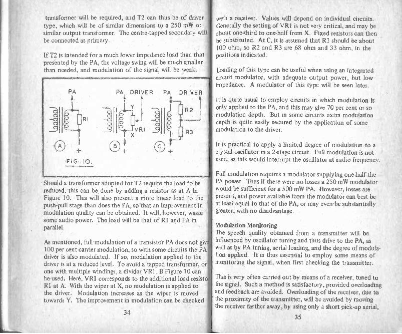
Should a transformer adopted for T2 require the load to bereduced, this can be done by adding a resistor as at A inFigure 10. This will also present a more linear load to thepush-pull stage than does the PA, so that an improvement inmodulation quality can be obtained. It will, however, wastesome audio power. The load will be that of RI and PA inparallel.
As mentioned, full m odulation' of a transistor PA does not give100 per cent carrier modulation, so with some circuits the PAdriver is also modulated. If so, modulation applied to thedriver is at a reduced level. To avoid a tapped transformer, orone with multiple windings, a divider VR1, B Figure 10 canbe used. Here, VR1 corresponds to the additional load resistorRI at A. With the wiper at X, no modulation is applied tothe driver. Modulation increases as the wiper is movedtowards Y. The improvement in modulation can be checked
with a receiver. Values will depend on individual circuits.Generally the setting of VR1 is not very critical, and may beabout one-third to one-half from X. Fixed resistors can thenbe substituted. At C, it is assumed that RI should be about100 ohm, so R2 and R3 are 68 ohm and 33 ohm, in thepositions indicated.
Loading of this type can be useful when using an integratedcircuit modulator, with adequate output power, but lowimpedance. A modulator of this type will be seen later.
It is quite usual to employ circuits in which modulation isonly applied to the PA, and this may give 70 per cent or somodulation depth. But in some circuits extra modulationdepth is quite easily secured by the application of somemodulation to the driver.
It is practical to apply a limited degree of modulation to acrystal oscillator in a 2 -stage circuit. Full modulation is notused, as this would interrupt the oscillator at audio frequency.
Full modulation requires a modulator supplying one-half thePA power. Thus if there were no losses a 250 mW modulatorwould be sufficient for a 500 mW PA. However, losses arepresent, and power available from the modulator can best beat least equal to that of the PA, or may even -be substantiallygreater, with no disadvantage.
Modulation MonitoringThe speech quality obtained from a transmitter will beinfluenced by oscillator tuning and thus drive to the PA, aswell as by PA tuning, aerial loading, and the degree of modula-tion applied. It is thus essential to employ some means ofmonitoring the signal, when first checking the transmitter.
This is very often carried out by means of a receiver, tuned tothe signal. Such a method is satisfactory, provided overloadingand feedback are avoided. Overloading of the receiver, due tothe proximity of the transmitter, will be avoided by movingthe receiver farther away, by using only a short pick-up aerial,
3435

or by feeding the transmitter signal into a lamp load asdescribed elsewhere. -
Feedback of sound from the receiver loudspeaker totransmitter microphone will cause howling. This is avoidedby keeping the receiver volume low, or by using phones, aswell as placing the microphone so as to avoid unnecessarypick up of sound from the receiver.
/ Modulation can also be checked by using headphones withthe monitor/wavemeter described.
Some circuits will be found to be more tolerant of mis-adjustment than others. Attempts to raise modulation beyothe level which is appropriate will cause a considerable loss ospeech quality. In any case of difficulty, it is worth while totest the modulator by feeding its output directly into a loud-
speaker. If distortion is present, operating conditions in theaudio amplifier have to be checked, as good speech qualitycannot be expected from the transmitter.
On the other hand, if the audio amplifier used alone providesan acceptable audio signal, but transmission quality is poorthe fault must be sought in modulator matching, tuning orloading of the PA, the level of drive from the oscillator to th'PA, or similar factors. It should b'e 'remembered that excessaudio power may easily be applied to a low -power PA. Thiswill be suspected if the speech quality of transmissionimproves when the audio level is reduced.
With the simple type of transmitter, it is usual to have a fixe'level of audio gain. Correct modulation is then achieved byspeaking at such a distance and volume as to give a normalaudio output if the amplifier were operating a loudspeaker.For simplicity, and to avoid, a high background noise andinstability troubles, no high -gain microphone pre -amplifieris generally used, and the amplifier is intended for closespeaking at about normal volume.
Audio IC ModulatorsAn integrated circuit audio amplifier will be found to givegood results as modulator. There is not much saving in spaceover the driver/push-pull type of circuit with discrete compon-ents and using three transistors, but the IC will be expected toprovide somewhat better speech quality and will have highergain. Extra audio power will also be readily available.
Many popular audio ICs will give 1 W or more output, with a9 V or similar supply. Though in some circuits the full outputwill not of course be required such ICs can have a lowquiescent current, and operate excellently with good economyat the lower output level needed with a PA running at perhaps250 mW to 500 mW input.
A useful IC is the TBA800, which can provide about 1 W witha 9 V supply, and does not require a very large number ofother components. Figure 11 is a circuit for this IC. C4should be closely connected to 4 and 5, and C3 is similarlynear 5 and 10. Audio input is via the isolating capacitor Cl,so operating conditions are not influenced by the DCresistance of the input circuit.
36 37

An 8 ohm load is suitable for this amplifier, which can bematned to the PA as described, by using a transformer. Theratio o' f' is item will not prove to be too critical and as moreaudio is available than required for a low power PA it will beof advantage to load the secondary with a resistor, asexplained.
Layout Of this audio amplifier is not critical, provided inputand output circuits are reasonably separated, and C3 and C4are placed as mentioned. A 50 x 50 mm printed circuit forthe TBA800 will be found in the "Handbook of IC AudioPreamplifier & Power Amplifier Construction" (BabaniPress BP35) and this board can readily be incorporated in atransmitter or transceiver.
CI
I OROK1
B
TBA8IOASI0A
I06
R2son
T
. T .C2 47 OpF
C3
C9
R3 loon 1000
6-7-11 C64 100),F
12
C55 I NF
100pr R4ICr
WIN C 4 IMO
T47NF TC8
ICIO
E+
+ C7 1000pFIMO=PM
F I G. I 2.
C
D_
Figure 12 is the circuit of a somewhat more powerful audioIC amplifier, which will prove very satisfactory with a PA of
increased input (say 1 W to 5 W). It may be used with asupply of down to 9 V, but is, more appropriate for 3 wattsoutput or over with a 12 V to 14 V supply, for a car, caravanor similar transportable transmitter. With a 4 ohm load,
current peaks will be about 300 mA to 500 mA, for outputsof 1 W to 4 W, and though current is naturally lower with asmaller audio output, the IC with sink is rather too large for"pocket" equipment.
Audio input to 8 is by the isolating capacitor Cl. It will befound that sufficient power is obtainable with a crystal micro-phone of high output type feeding the IC here. The ICrequires a heat sink. With the load increased to 8 ohm,peak current falls to about 300 mA at 14 V, and output 3 W.
This IC can be fitted to a board along similar lines to thatsuitable for the TBA800 and no particular difficulty shouldarise in wiring this, or preparing a printed circuit.
An IC amplifier, in common with other amplifiers, should notbe operated without a suitable load. The load must not bebelow the minimum quoted, or heavy peak currents maydamage the IC.
A test should be made by feeding the audio amplifier into a4 ohm or 8 ohm speaker. Input may be taken from a tuneror other convenient source, or from the microphone to beused. With the latter acoustic feedback from loudspeakerto microphone must be avoided in the usual way.
MatchingIt is convenient to use a transformer for coupling the audioIC to the power amplifier of the RF section. This providesDC isolation of circuits, and also allows the choice of asuitable ratio to give satisfactory impedance matching.
With an audio IC, the output load intended will generally below and may be from about 4 ohm to 16 ohm (actuallydesigned for the direct connection of an appropriate speaker).So the coupling transformer will need to have a step-up ratio,since the modulation impedance of the PA will be greater thanthat appropriate for the IC amplifier. The ratio will naturallydepend on operating conditions but may be around 1:2. Thiscan be determined as described later. As an audio IC of the
38 39
type described will operate satisfactorily with a range ofimpedances (though with a falling off in maximum audiopower output if the load is too high) there is useful latitudein the coupling ratio. The fact that excess audio power willbe available for a lower power PA also means that resistiveloading can be included. As this load is constant throughoutthe audio cycle, such loading will enhance operatingconditions.
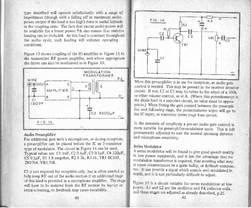
Figure 13 shows coupling of the IC amplifier in Figure 1 tothe transmitter RF power amplifier, and where appropriatethe driver can also be modulated as in Figure 10.
C2 3500pF
F I G.13.
Audio PreamplifierFor additional gain with a microphone, or during reception,a preamplifier can be placed before the IC or 3 -transistortype of modulator. The circuit in Figure 14 can be used.Typical values are: Cl 1nF, C2 0.1µF, C3 0.1p.F, C4 320/.2F,C5 0.5µF, RI 1.8 megohm, R2 8.2k, R3 lk, TR1 BC108,2N3704. VR1 50k.
Cl is not required for reception only, but is often needed tohelp keep RF out of the audio section if an additional stageof this kind is provided as a microphone amplifier. The stagewill have to be isolated from the RF section by layout orextra screening, or feedback may cause instability.
40
FIG. 14.
C2
MIKE'
I I
T
S
I 1
+I R32
TRI
I I --C3
4
VRIC 5
A
When this preamplifier is in use for reception, an audio gaincontrol is needed. This may be present in the receiver detectorcircuit. If not, C2 or C3 may be taken to the wiper of a 100kor other volume control, as at A. (Where this potentiometer isthe diode load in a superhet circuit, its value must be appro-priate.) When fitting the gain control between the preampli-fier and following stage, the potentiometer wiper will go tothe IC input, or transistor driver stage base circuit.
In the interests of simplicity a pre-set audio gain control ismore suitable for preamplifier -modulator units. This is leftpermanently adjusted to suit the normal speaking distanceand microphone sensitivity.
Series ModulatorA series modulator will be found to give good speech qualityin low power equipment, and it has the advantage that nomodulation transformer is required, thus avoiding what mayin some circumstances be a quite bulky, or difficult compon-ent. It can provide a signal which sounds well modulated indepth, and it is not particularly difficult to adjust.
Figure 15 is a circuit suitable for series modulation at lowpower. LI and L2 are the oscillator and PA collector coils,and these stages are adjusted as already described, p.25.
41

V R I [4-2K
C2
RI2.2K
FIG.1 5.
L2T R I
CI 3.3NF
TR2AC14 2
C3640
F
TR2 is the series modulator, and should be of similar orlarger power handling rating than the input to TR1. WhereasTR1 is an NPN transistor, TR2 is a PNP device. For aBFY51 or other PA running at a few hundred milliwatts, anAC128, AC142, or similar audio type transistor will be satis-factory for TR2.
The base coupling coil for Ll, supplying drive to TR1, isreturned to the emitter of TR1, not to the negative line.Cl is a by-pass capacitor, and should be near TR1 emitter,offering a short RF path.
Base bias for TR2 is obtained from VR1 and R1 Adjustmentof VR1 should begin with most of the resistance out ofcircuit. A high resistance voltmeter is clipped from X tonegative line. TR1 should for preference have been alreadytuned up normally, as this, and the drive obtained from Ll,will considerably influence the current TR1 would pass. VR1is then adjusted so that the voltage at X is approximately halfthe supply voltage. That is, about 4.5 V for a 9 V supply, or6 V fora 12 V supply.
Audio input applied to TR2 via the capacitor C2 (2i/F).When the base of TR2 is driven positive, TR2 emitter currentfalls, while with negative drive emitter current rises. Thevoltage reaching TR1 is thus swung up and down at audiofrequency, with consequent modulation of the carrier.
It will be found that speech quality improves if the voltageacross TR2 - that is, from negative line to point X - is alittle over one-half the supply voltage. This can be securedby appropriate adjustment of VR1. This setting is not verycritical, and VR1 can be replaced by a fixed component ofnear value to that giving best results, VR1 being disconnectedand measured with a meter.
If drive from Ll, tuning of L2 and loading here, audio drivevia C2, and VR1 are all adjusted, excellent speech quality canbe obtained. But none of these adjustments are of a particu-larly tricky or critical nature. Audio input to C2 should betaken up to the point where the signal sounds stronglymodulated, when tuned in by a receiver or monitor.
With X set at half the supply voltage, TR1 is operating at onlyhalf the voltage which could be present with transformercoupled modulation. As a result, RF output is lowered.-However, a useful output is available. Compensation can bemade to some extent by increasing the supply voltage - twoextra 11/2 V cells will raise this from 9 V to 12 V. The ratingof TR1 need only be twice the supply voltage (not four times,as with transformer modulation). Two audio stages will bethe minimum to provide audio drive for TR2.
This circuit will function satisfactorily with a wide range oftransistors and power inputs, from flea power to some wattsinput. In each case base bias for TR2 is set as described.With other than very small power, TR2 will require a heatsink to match that used with TR1.
The circuit can perform well when RF drive to TR1 is a littlemeagre. This is usually not so with transformer coupled
42 43

modulation of the collector, where drive requirements arehigh during those instants when the collector swings toapproximately twice the supply voltage.
3 -Stage 144 MHz TransmitterIf the number of stages in a VHF transmitter is to be keptdown, it is necessary to start with an oscillator at a high
frequency. This avoids the need for so many multipliers.Thus an oscillator working at 72 MHz to 73 MHz, followed
by a doubler, will give an output in the 144 MHz to 146MHz band. It is poor practice to energise the aerial from adoubler, because of the harmonic energy present, so the
final power amplifier should work straight through at the
same frequency. With these points in mind, a 3 -stagetransmitter for 144 MHz can consist of a 72 MHz oscillator,doubler operating with 72 MHz input and furnishing144 MHz output, and PA functioning at 144 MHz. Thecircuit described here is of this type.
TR1 in Figure 16 is the crystal controlled oscillator.Collector current is about 4 mA to 5 mA with the stagenot oscillating, and 8 mA to 10 mA when oscillating.Collector current, and RF output, can be adjusted to someextent by changing the value of RI or R2.
Ll is ten turns of 32 swg enamelled wire, side by side, ona 4.5 mm diameter former, with VHF grade core. The
crystal can be a miniature plug-in or wire ended type.Adjust tuning of LI, with the aid of an indicating wavemeter,for maximum RF, assuring the oscillator always starts when
switched on, as explained earlier. Check that the RF is at72 MHz, as harmonically cut crystals can be tuned to operateat a different multiple of their fundamental. Various othertransistors than the type shown will be found to operate in
this stage. As there are only three stages in all, and becauseof the reduced gain at VHF, it is essential to obtain the bestefficiency from each section - oscillator, doubler, and finalamplifier - to avoid the need for an extra transistor betweendoubler and TR3.
N QQ.O.'cr '0000\
co C
cmm
^-{
NC.
Et th
COO 0_ 0_0
t!1 0 0-J
Nc-
LL.LL
C Z0 Ct.
N Z0
C
0;
uO
cc
MEM
Nc c 0
I
0N
(11
44 45
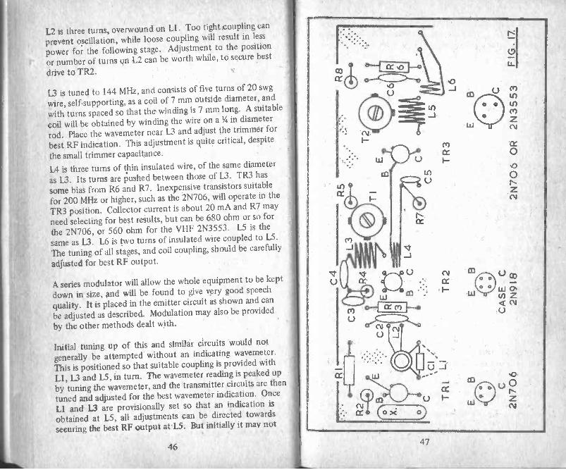
L2 is three turns, overwound on LI. Too tight coupling can
prevent oscillation, while loose coupling will result in less
power for the following stage. Adjustment to the position
or number of turns on L2 can be worth while, to secure best
drive to TR2.
L3 is tuned to 144 MHz, and consists of five turns of 20 swg
wire, self-supporting, as a coil of 7 mm outside diameter, and
with turns spaced so that the winding is 7 mm long. A suitable
coil will be obtained by winding the wire on a1/4 in diameter
rod. Place the wavemeter near L3 and adjust the trimmer for
best RF indication. This adjustment is quite critical, despite
the small trimmer capacitance.
L4 is three turns of thin insulated wire, of the same diameter
as U. Its turns are pushed between those of U. TR3 has
some bias from R6 and R7. Inexpensive transistors suitable
for 200 MHz or higher, such as the 2N706, will operate in the
TR3 position. Collector current is about 20 mA and R7 may
need selecting for best results, but can be 680 ohm or so for
the 2N706, or 560 ohm for the VHF 2N3553. L5 is the
same as 13. L6 is two turns of insulated wire coupled to L5.
The tuning of all stages, and coil coupling, should be carefully
adjusted for best RF output.
A series modulator will allow the whole equipment to be keptdown in size, and will be found to give very good speechquality. It is placed in the emitter circuit as shown and can
be adjusted as described. Modulation may also be provided
by the other methods dealt with.
Initial tuning up of this and similar circuits would not
generally be attempted without an indicating wavemeter.This is positioned so that suitable coupling is provided with
Ll, 13 and L5, in turn. The wavemeter reading is peaked up
by tuning the wavemeter, and the transmitter circuits are then
tuned and adjusted for the best wavemeter indication. Once
LI and L3 are provisionally set so that an indication isobtained at L5, all adjustments can be directed towards
securing the best RF output at L5. But initially it may not
46
Eft,
47

be practical to check for RF at L5 only, as should Ll bemis-tuned TR1 will not oscillate, while wrong tuning of L3can also cause a complete absence of output from TR3.
Figure 17 is the layout of components for this circuit. L4 isshown separated from L3 for clarity. This also applies to L6,which is of insulated wire, with turns between those of L5.
Connections should be as short as possible, this includingemitter, by-pass capacitor and other earth returns. It will notbe feasible to drive the 2N3553 type of transistor to full
output, but its VHF performance is better than that of the2N706. Once the circuit is providing output at 144 MHz,individual adjustment to component values, and tuning andcoil coupling, will allow the best possible performance to beachieved with the three stages.
Transmitter for 80 or 160 mThe 3.5 MHz band offers local short range contacts and longer
distance working by sky wave, while the 1.8 MHz band is quiteoften used for low power. Transmitters for these frequenciesare easily constructed and can operate with good efficiency.Many transistor types exist for use at frequencies under about4 MHz, and those chosen can best be for frequencies up to
10 MHz or so. Higher frequency types are satisfactory, butthe chances of high frequency parasitics increase with HFand VHF transistors. It is thus a disadvantage to fit devices
which could operate up to the VHF region, when the equip-ment is for the low frequency hands.
In Figure 18 TR1 is the crystal controlled oscillator, with a
fundamental frequency crystal X. It will thus be 3.5 MHz t63.8 MHz for the 80 in band, or 1.8 MHz to 2.0 MHz for
160 m. For CW operation on 80 m, the operating frequencyis generally from 3.5 MHz to 3.6 MHz. RI and R2 providebase bias, and Cl is for decoupling, with R3 in the positiveline. LI is tuned approximately to the crystal frequency, in
the way described. C2 and C3 in series are across LI, and
their junction provides a drive point for the base of TR2. This
stage has base bias from R5 and R6, and output is into thetapped coil L2. L3 is for aerial coupling.
Component values for Figure 18RI 33 kR2 10 kR3
R4R5
R6
R7CI
C2
C3
C4
CS
TR1
TR2
270 ohm W
22 ohm10k33 k33 ohm0.1 /IF1.5 nF siliver mica1 nF silver mica400 pF silver mica20 nFBFY51 etc.BFY51 etc.
itilitiamemmrimMinianrwsremuallialiblaLlia.1111anailmmajli
48 49

80 m inductors. LI is thirty-tivo turns of 32 swg enamelled
wire, wound side by side on a 3/16th in or 5 mm diameter
former, with core. It might in some circumstances be neces-
sary to change the number of turns slightly, for crystals nearthe band edges, according to the type of core and tolerances
of C2 and C3. L2 is wound with 24 swg enamelled wire on
a 3/8th in or 10 mm former, and is twenty-three turns, with
the collector tapping seven turns from the C5 end of the
winding. L3 is four turns, overwound on L2, but coupling
here can be changed to the aerial.
160 m inductors. LI is increased to fifty-five turns, in a
compact pile. The core for L2 is a piece of ferrite rod
1 in x 3/8th in in diameter, and L2 is twenty-eight turnsof 24 swg enamelled wire, tapped at eight turns, with L3
having five turns, overwound. The turns are on a thin cardtube so that the ferrite core can be moved for tuning
purposes.
The circuit will operate with a wide range of voltages, up tothe maximum for the transistor types, and where necessaryallowing for modulation as described. R7 may be disconnec-ted for collector modulation of TR2. It is possible tomodify the relative values of C2 and C3, and the positionof the tap on L2, to suit the operating voltage or transistors.Miniature plug in crystals will allow moving to various fre-
quencies on the band. Check that all RF output ceases when
the crystal is removed.
RF Power AmplifiersWith a final radio frequency power amplifier running with an
input of about 200 mW to 400 mW or so, economical opera-
tion is possible from small batteries. This power is sufficient
for point to point contact over. reasonable distances. But for
larger yet still portable equipment an increase in power level
may be wanted, and it may be practicable to draw currentfrom a vehicle accumulator in some cases, or to have this as
an alternative to a 12 V or similar dry -battery supply. Even
with a small battery, an increase in power is feasible if it isrealised that earlier replacement of the battery pack will benecessary.
With many circuits it is possible to add a larger poweramplifier. In some circumstances this can replace theexisting PA, but in others the low -power PA can performas a driver stage for the new PA, which will have a higherpower rating.
Figure 19 shows the basic PA output stage, and this can be abasis for increasing power on 160 m to 2 m. This stage mayrun with the same voltage as the remaining circuits of thetransmitter, or may be operated from a different voltage,where necessary, and it can be modulated by any of themethods described.
f the existing PA transistor is to be changed, LI, L2, 1.3and L4 will be present. But where the stage will bedditional to the existing circuit, LI will be the old PA collec-or winding, and L2 the aerial coupling winding, so that aurther transistor, with L3, L4 and associated components,ill be added.
50 51

As an example of adding this further stage as power amplifier,it can follow the 2 -transistor circuit in Figure 18. Ll and L2
will thus be present. L3 and L4, Figure 19, can be wound in
the same way as L2 and L3, Figure 18, for 80 m operation.
A 400 pF capacitor is used across L3 (Figure 19) and tuning
is by the adjustable core. A suitable transistor is the BD139.
Tuning up of all stages will be as already described, and for
test and tune-up purposes L4 can be connected to a 12 V 2.2
watt bulb. The stage can be modulated by the larger ICmodulator shown, transformer coupled to the collector
circuit.
Layout must avoid feedback from L3 or associated circuits,to LI, or the base circuit. This is best arranged by havingthe new stage in a small screening box, or at least having a
screen between this and the previous stage. Remember
that in all transmitters the RF output should cease if the
crystal is disconnected or taken out. If this is not so,oscillation is arising elsewhere and must be prevented. Toimprove stability, a 10 ohm to 22 ohm resistor may beinserted at X, near the base.
Cl and L3 will of course depend on the working frequency.C2 is a by-pass capacitor, and should be arranged to offer ashort RF path from L3 and L4 to PA emitter and groundline. C2 cannot be of large value when collector modulation
is used, as it is effectively across the audio output of themodulator. It can generally be about 10 NF for LF circuits,but can be reduced to 4.7 NF or 1 NF for 28 MHz or 144
MHz. With series modulation (Figure 15) the same consider-
ations apply to the capacitor which will be from PA emitterto ground line. With this form of modulation, C2 can now
be 0.1 tiF or larger for LF transmitters, as it is no longer
across the modulator output.
With three stages, modulation can now also be applied to the
driver, as shown. This increases the overall modulation dept'
Modulator or RF voltages must not be allowed to travel
along the positive line to earlier stages, such as a microphone,
pre -amplifier or oscillator. It may be necessary to place aresistor as RF stopper in series with L3 at the positive end,with C2 directly from L3 to ground. The resistor has to be oflow value to avoid loss of voltage, and 10 ohm can be fitted.A large capacitor - say 1000 AF or more - should beconnected across the modulator positive and negative lines,near the modulator.
When initially setting up a PA stage such as that in Figure 19,a meter should be included in the positive supply, so thatcurrent can be checked. A multi -range instrument set to its1 ampere range will generally be suitable.
Adjustable cores are not shown for Ll and L3, but are usedfor the LF band's or 28 MHz. For 144 MHz, tuning mayinstead be by small pre-set capacitors, with self-supportingcoils. If core -tuned coils are employed, it is essential thatthe core material is of a grade suitable for these frequencies.
The following list of transistor types will give the moreimportant operating conditions. The suggested -uses are not ofcourse the only ones to which a particular transistor could beput. Transistors with high collector voltage ratings will be ofspecial use where transformer coupled collector modulation isto he used. Figure 20 gives lead information on the typeslisted. It is not possible to list all transistors which might be
52 53

...,
"Z":1
E..,> 0
1:3
-o
.o
,,,i
"-
--o:it-6
8
m
,_-
47:
c.:1-.
o
,..0
5r--
L:
^3:
vs-`6)
,..,o
4.;.-:
Em
TIT-..7.
...:
-'f,'
9.L.
'-',G
...:'
-.,6..
u:
-8
y
::-1
4T...
=>',.--....,t-
:-=',
:d
-y.''''
>
ocz:
:ILa.
.,,---
iIOoi.0
I2ooN
I2ooN
N:1:."
2oLr-,
N
I2ooen
IN2o
I20o-
I2oN
N
2oN
NI2in-
cl-,e-
cCN
,-00N
0C(,)
0ir,m
_00in
.-=o0
00
..-- Lr,
00
- (--......,-
,,,-;,--in- N.- cD
NCm
Cd-
Cm
0-1'
000
07.t.
71--
C..)'-4
<-,---0Cc)
<P00
<E00
<E00
<
00
y..
-,<
00<in
<--
eai,:3
Cr)71V7 - - - - - ,n - c )
N09
Z(-4
m,i0
(ue,'",a..-- -
2
i..0
r---
Zc.,
-7,-,'t'''''enz,...
<LNNNzCI
->-fa.ac
cntg-'-')t.,-..-si
Cr'("")
(Th
rd
r'-)
,'n"cnzCV
v-,
,--,c7-z,"-'1
used in the RF section of a transmitter, and there are othertypes which will prove to be satisfactory. The upperfrequency limit of a transistor should be substantially higherthan the actual working frequency required.
Data are in the following order: Lead information (Fig. 20), ICor maximum rated collector current, Vc-e or maximumcollector to emitter voltage, P or maximum device ratedpower dissipation, and fT (frequency).
No single rating should be exceeded. Maximum operatingconditions may thus be limited by current, voltage, or powerdissipated. Heat sinking is necessary for the larger transistorsunless used at such lower power that the temperature rise isnot important. All are NPN types.
Transceiver SwitchingSwitching from reception to transmission can be with a push -switch (push to talk) or a small rotary switch, marked withreceive and transmit positions. With the latter type of switch,it is convenient to fit a 3 -way component, and the thirdposition can be used for "off' to avoid a separate on -offswitch.
5554

Where the transmitter and receiver are separate units, a 2 -pole
switch is adequate, as in Figure 21. During reception, section
Si takes the aerial to the receiver, and S2 applies batteryvoltage to this section. The loudspeaker is permanentlyconnected and the receiver has its own audio amplifier.
This method has some advantages. The transmitter, with its
modulator, will be a completely separate unit. The receiverwill operate alone, and can be changed or replaced without
disturbing any part of the transmitter circuit. Switching is
simplified. A disadvantage is that the receiver requires itsown audio amplifier, but this need take up little space.
TRANSMITTERR F
SIR S2
RECEIVERR F-DET
IN
AUDIO OUTAMPLIFIER
--is.4]T R
eRS3'$T
FIG.22.
In Figure 22 switching has been added so that a single audioamplifier is in use for both transmission and reception. Switch,sections Si and S2 operate as before. S3 transfers the inputcircuit of the audio amplifier to the receiver for reception,and to the speaker (as microphone) for transmission. S4
switches the audio output to the speaker for reception, orradio frequency section of the transmitter to providemodulation, as required.
The receiver now needs no audio amplifier or output stage,but there is additional switching, with interconnection ofunits. It is necessary to avoid unwanted coupling of RFenergy from SI or the aerial circuit, to S3 or the audioamplifier input, as feedback of this type will causeinstability on speech peaks or continuous instability.
Modifications of these circuits are possible. In Figure 22the speaker is switched from receiver output stage tomodulator input stage, so that a separate microphone isnot required. This is most easily arranged by having thespeaker returned to the negative line for both circuits,with capacitor coupling, so that a further switch pole willtransfer the speaker as shown (see Fig. 8). But as amicrophone need occupy little space, it may be preferredto retain the speaker for reception only.
With some commercial equipment, additional switch polesare present, so that greater isolation can be securedbetween audio amplifier input and output circuits, orbetween audio input and aerial circuits.
For push-button change-over, no intermediate off position willbe available and the main on -off switch may then be separate,or may be incorporated in the receiver audio gain, controlwhen present. The best method of change -over is by push-button switch, which automatically returns to "receive" whenreleased. A spring biased toggle switch, similarly used, is alsosatisfactory. Easily obtainable small push switches have alimited number of poles, and this may in part help decidewhat type of change -over switching can be used.
PNP TransmitterFigure 8 is the circuit of a modulator which has a positiveground line, and using PNP transistors. Figure 23 shows apositive ground line oscillator and power amplifier intendedfor use with this modulator, and running at about 200 mW.It will be seen that the circuit arrangement folloWs thatemployed with NPN transistors and a negative ground line.No modulation is applied to the crystal controlled oscillator
56 57
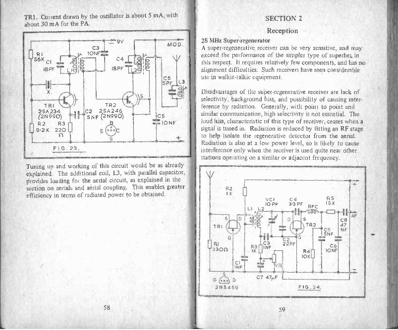
TR1. Current drawn by the oscillator is about 5 mA, withabout 30 mA for the PA.
Tuning up and working of this circuit would be as alreadyexplained. The additional coil, L3, with parallel capacitor,provides loading for the aerial circuit, as explained in thesection on aerials and aerial coupling. This enables greaterefficiency in terms of radiated power to be obtained.
58
SECTION 2
Reception28 MHz Super-iegeneratorA super -regenerative receiver can be very sensitive, and mayexceed the performance of the simpler type of superhei, inthis respect. It requires relatively few components, and has noalignment difficulties. Such receivers have seen considerableuse in walkie-talkie equipment.
Disadvantages of the super -regenerative receiver are lack ofselectivity, background hiss, and possibility of causing inter-ference by radiation. Generally, with point to point andsimilar communication, high selectivity is not essential. Theloud hiss, characteristic of this type of receiver, ceases when asignal is tuned in. Radiation is reduced by fitting an RF stageto help isolate the regenerative detector from the aerial.Radiation is also at a low power level, so is likely to causeinterference only when the receiver is used quite near otherstations operating on a similar or adjacent frequency.
59

Figure 24 shows the RF and detector stages of a super -regenerative receiver for 28 MHz. TR1 is primarily a buffer,and no amplification is expected here. It is scarcely worthwhile providing a tuned circuit, though it would improveefficiency. R1 is for source bias of TR1.
TR1 drain is coupled to L2 by LI, and L2 is the only tunedcircuit present. VC1 allows reception over the whole 28 MHzband. C2, and the core setting of L2, determine the actualfrequency range.
Regeneration arises by the feedback via C4, and is quenchedby the network R4/5 and C5/6. Transistors such as the2N5459 give excellent results in this circuit. There is someslight advantage in using a VHF type of FET for TR1, butthis type may result in, too strong regeneration in the TR2position. Regeneration is controlled by VR1, and the hissshould commence with this rotated about half to two-thirdsfrom its zero (negative end) position. C4 has considerableinfluence on regeneration and can generally be as shown,though 1.8 pF to 4.7 pF can be tried if necessary, or a 5 pFtrimmer.
The circuit is followed by an audio amplifier. For a verysmall receiver for phones, a single stage is adequate. A 2 -stage amplifier will provide reasonable loudspeaker reception.The amplifier may be that used as modulator on transmission
L2 is wound on a former approximately 5 mm in diameter,and is fourteen turns of 32 swg enamelled wire, side by side.LI is eight turns, near the C3 end of L2. A space of about2 mm between LI and L2 will be satisfactory. If Ll is verynear L2, regeneration may be prevented, while unnecessarilyloose coupling will reduce volume. The core of L2 is adjustedso that the wanted frequencies are found with VC1 about hal,closed.
The RF choke can be wound on a carbon 2.2 megolun resistowhich is about 3'h mm in diameter and 10 mm long, or upon
60
piece of insulated material of similar size. It has one hundredturns of 42 swg wire, in two compact piles each of fifty turns.The wire ends are soldered to the resistor leads, which supportthe choke. The turns must not be varnished or waxed, buttouches of adhesive can be used to avoid them coming loose.
VR1 has to be turned beyond the point where oscillationbegins, so that a loud hissing is heard. This ceases, as men-tioned, when a signal is tuned in. Adjustment of VR1 is notvery critical, except with very weak signals. The usual typeof telescopic aerial is fitted.
Layout of the components does not prove to be too importantprovided short leads are possible for TR1; Ll/L2 and TR2,including C3, and the variable capacitor with C2. A suitablelayout for 0.15 in matrix perforated board is shown inFigure 25. A miniature tuning capacitor of the type madeby Jackson Bros. (the C.1604) will allow size to be keptdown, though any small capacitor of low value will give thesame results.
A rim control potentiometer, as used in pocket and smallradio receivers for audio gain, will also save space. As thiscomponent is a potential divider any value from about 5 kto 25 k is satisfactory. Alternative, a small linear potentio-meter of ordinary type can be fitted to the case near VC1.The finished receiver will more easily slip in a pocket if theknobs are at the top. It would be possible to accommodatethese components on a somewhat smaller board, but is noteasy to obtain speaker units of less than about 21/4 in in dia-meter, so this item sets one minimum dimension.
If the layout shown is followed, wiring should be quite easy.Position the coil slug towards the LI end of the coil. The RFand detector sections of the receiver may be tested by connec-ting medium or high impedance phones from C8 to thenegative line.
This circuit, followed by a simple AF amplifier, can be usedfor a receiver to be employed alone. Current can then be
61

I
C3D
T R2 C4
taken from a small 9V layer battery. If the circuit is fitted ina transceiver, power is drawn from the transmitter sectionbatteries.
2 -Metre Super -Reg ReceiverThe simplicity of the super -regenerative receiver makes it ofadvantage for 144 MHz, provided its limitations are remem-bered. It is readily adapted to tune the VHF bands, and asuperhet of equal sensitivity would need considerably morecomponents.
The circuit can be basically as shown for 28 MHz (Fig. 24).Both FETs should be for VHF use, with a top frequency of200 MHz or higher. It will be necessary to modify LI andL2, and the RF choke. Self-supporting coils are convenient,in view of the small number of turns necessary. The chokemay be constructed along the same lines as described for28 MHz, but is wound with turns side by side, over alength of about 8 mm. L2 is three turns of 18 swg wire,self-supporting, and arranged as in Figure 26. It is 12 mmdiameter and 17 mm long. C2 is a miniature 15pF pre-set. LIis two turns, near L2, spacing being adjusted for best recep-tion. Very short leads should be obtained in the RF circuits.
TR1/2G S D AERIAL
RI
R2
CSR
C6illrilC1111
C4
R5 Warsomtk .
8 Ilk -"Ns.L2
R3C7
F I G.26.
This section is followed by a 2 -transistor, or transistor and ICamplifier, for loudspeaker reception. C8 runs to an audio gainpotentiometer, AF being taken from the control wiper.
63

28 MHz Mixer/OscillatorA self -oscillating mixer for use in the 28 MHz band is shown in
Figure 27. The whip aerial is coupled by Cl to the aerial coil
Ll, which has the parallel capacitor C2. The secondary of Ll
provides input to TR1, and RI and R2 provide base bias.
The oscillator coil L2 has coupling windings for emitter andcollector. Trimmer T1 and the core of L2 allow setting up forthe 28 MHz band, and manual tuning is by the small variable
capacitor VC1. R3 provides emitter bias. Output from themixer is via R4, to the primary tapping of the first IF trans-
former. It will be found in some cases that R4 is not neces-
sary to maintain stability, but it is required if continuouswhistles accompany reception.
As aerial tuning is relatively flat, and only a narrow band of
frequencies will be required, variable tuning is not necessaryhere. Instead, the core of Ll is peaked up for best receptionon the wanted frequency, or at about the middle of the
range of frequencies which will be received.
Ll is wound with 32 swg enamelled wire, using a 5 mm orsimilar diameter former, with adjustable core. Begin at poin
1 and fix the wire with a spot of adhesive. Wind twelve turnsside by side, and finish this coil at 2. A very small space isleft, and the wire is fixed at 3. Four turns are then wound inthe same direction as before, and the coil terminates at 4.The wire ends are long enough to reach the various connectingpoints. The core is located towards the bottom of the twelveturn winding.
The oscillator coil L2 is wound on a similar former. It hasseven turns for the tuned winding, four turns for the collectorwinding, and two turns for the emitter winding. The wire canbe 32 swg enamelled as before, or thinner wire may be usedfor the two smaller windings. Points 1, 2 and 3 are the startof each individual winding, and all windings are in the samedirection. The seven turn winding is put on first, and thetwo smaller windings are placed on top of this, to be tightlycoupled.
Adjustment of T1 and the core allows the 28 MHz band to betuned without too violent oscillation, and VC1 covers anadequately large band. By fitting a small capacitance here,the need for a reduction drive is avoided.
When testing this circuit for the first time, note that thefrequency coverage depends on L2 and T1 (with VC1). Whencoverage is suitable, the core of Ll is merely peaked for bestvolume. The positive supply line from RI passes to thepositive line of the IF board, or pin 3 of IFT1.
With an intermediate frequency of 465 kHz, L2 may be tunedeither 465 kHz above the reception frequency, or 465 kHzbelow this frequency. This has no practical effect on effici-ency, but it is more usual to have the oscillator tuned I -IF ofthe aerial circuit.
A range of NPN mixer and oscillator transistors will operate inthis circuit. The BF194 is recommended, but other transistorswith fT going up to 200/250 MHz, and hFE of 100 or so willoperate.
64 65
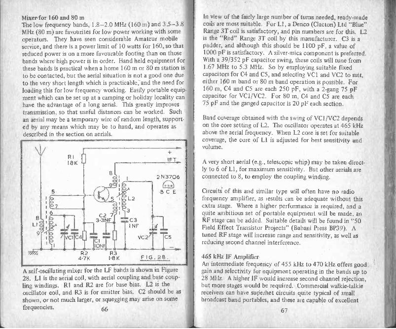
Mixer for 160 and 80 mThe low frequency bands, 1.8-2.0 MHz (160 m) and 3.5-3.8MHz (80 m) are favourites for low power working with someoperators. They have seen considerable Amateur mobileservice, and there is a power limit of 10 watts for 160, so thatreduced power is on a more favourable footing than on thosebands where high power is in order. Hand held equipment forthese bands is practical when a home 160 m or 80 m station isto be contacted, but the aerial situation is not a good one dueto the very short length which is practicable, -and the need forloading this for low frequency working. Easily portable equip-ment which can be set up at a camping or holiday locality canhave the advantage of a long aerial. This greatly improvestransmission, so that useful distances can be worked. Suchan aerial may be a temporary wire of random length, support-ed by any means which may be to hand, and operates asdescribed in the section on aerials.
2 N 3706
4: TIIONTR2 R3
4.7K 1.81( FIG.28.
A self -oscillating mixer for the LF bands is shown in Figure28. Ll is the aerial coil, with aerial coupling and base coup-ling windings. RI and R2 are for base bias. L2 is theoscillator coil, and R3 is for emitter bias. C2 should be asshown, or not much larger, or squegging may arise on somefrequencies. 66
Id
In view of the fairly large number of turns needed, ready-madecoils are most suitable. For Ll, a Denco (Clacton) Ltd "Blue"Range 3T coil is satisfactory, and pin numbers are for this. L2is the "Red" Range 3T coil by this manufacturer. C3 is apadder, and although this should be 1100 pF, a value of1000 pF is satisfactory. A silver -mica component is preferred.With a 39/352 pF capacitor swing, these coils will tune from1.67 MHz to 5.3 MHz. So by employing suitable fixedcapacitors for C4 and C5, and selecting VC1 and VC2 to suit,either 160 m band or 80 m band operation is possible. For160 m, C4 and C5 are each 250 pF, with a 2-gang 75 pFcapacitor for VC1/VC2. For 80 m, C4 and C5 are each75 pF and the ganged capacitor is 20 pF each section.
Band coverage obtained with the swing of VC1/VC2 dependson the core setting of L2. The oscillator operates at 465 kHzabove the aerial frequency. When L2 core is set for suitablecoverage, the core of Ll is adjusted for best sensitivity andvolume.
A very short aerial (e.g., telescopic whip) may be taken direct-ly to 6 of Ll, for maximum sensitivity. But other aerials areconnected to 8, to employ the coupling winding.
Circuits of this and similar type will often have no radiofrequency amplifier, as results can be adequate without thisextra stage. Where a higher performance is required, and aquite ambitious set of portable equipment will be made, anRF stage can be added. Suitable details will be found in "50Field Effect Transistor Projects" (Babani Press BP39). Atuned RF stage will increase range and sensitivity, as well asreducing second channel interference.
465 kHz IF AmplifierAn intermediate frequency of 455 kHz to 470 kHz offers goodgain and selectivity for equipment operating in the bands up to28 MHz. A higher IF would increase second channel rejection,but more stages would be required. Commercial walkie-talkiereceivers can have superhet circuits quite typical of smallbroadcast band portables, and these are capable of excellent

results. Suitable transformers for this frequency are readilyavailable.
Figure 29 is the circuit of a 465 kHz IF amplifier using twoBF195 (or 2N3704) transistors. Two double tuned and onesingle tuned transformers allow very good results, and allcomponents can be fitted in a small space. A little savinghere would be accomplished by using three single tunedtransformers.
IFT1 receives input from the mixer. The connection is to 1for a dual -gate FET mixer, but otherwise to tapping 2.
Secondary output from tapping 5 is to TR1 base. Base biasis largely determined by RI, R4, and VR1, so these items mustbe of the values shown. TR1 collector output is to theprimary of IFT2, and the secondary couples to TR2 base viaC2, with base bias for TR2 from R3. TR2 supplies the singletuned IFT. The decoupling components R5 and C3 can proveto be unnecessary with the 2N3704s.
Any AM receiver detector diode or similar diode will besuitable for Dl. Its polarity must be as shown, becausesignals can then shift TR1 base negative, via R4 and R2, toprovide automatic volume control. After demodulation byD1, audio signals are taken at any wanted level from theslider of the volume control VR1.
IFT pin identification is for Denco (Clacton) Ltd components.These are pre -aligned, so the cores should be left as they are,except for a final touching up after the circuit has beenfound to operate satisfactorily. A properly shaped trimmingtool is advised (such as that available from the IFT maker) asa wedge-shaped blade can crack and jam the cores. Final IFTadjustment is best by providing a steady signal, and clipping ahigh resistance voltmeter across VR1. The cores are then setfor maximum reading, which corresponds to the highest AVCvoltage.
The circuit will provide very good gain and sensitivity. If it is
1CL
O
NC
Cr 0
SU, rn
u_
IL_
9
68 69

found that instability arises with alignment correct, this canbe prevented by adding a resistor between the IFT secondaryand base of the stage; or between collector and the followingprimary. The transistors mentioned have a wide spread in
gain, so it may be necessary to try values from about 47 ohmto 470 ohm or so, using the lowest values which allow stableoperation at low signal levels. The resistors should be closeup against the transistor, with very short leads, but will notprove to be critical in value.
This amplifier may be constructed as an individual unit, or canbe assembled on a board carrying mixer and oscillator com-ponents. The layout of parts can best be similar to that in thecircuit, with stages following each other and input and outputcircuits at the ends of the board.
It will be appreciated that this same IF strip can be used with avariety of mixer and audio circuits, for any band up to 28MHz. It will be of advantage when minimum size is notessential. A rather smaller 465 kHz strip is described later.
Audio output via R7 can best be to a preamplifier (such asthat in Figure 14). This can be followed by a driver and push-pull audio panel. The audio section will then have fourtransistors in all. Alternatively, an audio IC can be used. Ifsomewhat less audio gain can be tolerated, then R7 may beconnected to the driver or audio IC input, the preamplifierbeing omitted.
Crystal Controlled ReceiverThe tunable receivers described have the advantage that othertransmissions can be copied on adjacent frequencies, so thattheir scope is increased. However, for 2 -way contact a crystalcontrolled receiver offers several advantages. Its frequency ofreception is rigidly controlled by the crystal, so that it isalways correctly tuned. In fact, no manual tuning controlwill be present. It is not susceptible to changes in frequencydue to battery voltage, vibration or similar factors. It cannot,of course, be used for the reception of signals on any otherfrequency for which a crystal is not available. Such a receiver
will generally be used with a second unit, also crystal con-trolled. It is possible for a home or base station to tune upfor transmission to suit the crystal controlled receiver, butthere is not much latitude for error and the transmitter willnormally be crystal controlled.
For communication in one direction the transmitter andreceiver will employ a pair of crystals which have a frequencydifference equal to the intermediate frequency of the receiver.An identical pair of crystals can be used for communication inthe other direction. A third station operating on the samefrequency will then be heard by both listening stations.
It is more usual to have the receiver oscillator working at ahigher frequency than the transmitter, though there is novery important reason why it should not operate on the lowfrequency side of the signal. So if the transmitter is to operateon, say, 28.5 MHz, and the receiver intermediate frequency is465 kHz, the receiver oscillator can use either 28.965 MHz, or28.045 MHz. In each case mixing of the signal and oscillatorfrequencies will give an output from the mixer stage of 465kHz, to pass to the intermediate frequency amplifier.
A circuit incorporating a crystal controlled oscillator is shownin Figure 30. LI is the aerial coil, and the whip aerial iscoupled to this by C1. LI , with parallel capacitor C2, is tunedto the transmitter frequency, or 28.5 MHz in the examplegiven. RI and R2 are for base bias of the mixer, and couplingis by the secondary of LI, Collector output of this stagepasses to the IF amplifier.
TR2 is the separate oscillator, and the frequency here is deter-mined by the crystal, which can be 28.965 MHz, as explained.C6, with the RF choke, allows feedback to the emitter. Thechoke can be any small component effective at these fre-quencies. It may be wound with 32 swg enamelled wire, on aY4 in diameter insulated rod or tube, fifty turns being provided.Oscillator coupling is by C5 to TR1 base.
With such a circuit, Ll is merely tuned for best reception, and
70 71

0_
NN-I I-
Nrr
c-
. 1
6m
zN
is not very critical. As is usual with a superhet circuit, thecritical frequency is that of the oscillator, and this is fixed bythe crystal. Normally, virtually no tuning of the receiver(except to peak the core of LI) will be required. However,the cores of the intermediate frequency transformers can eachbe given a small adjustment, if this proves necessary, so thatthey fall exactly on the mixer output frequency. This willcompensate for any slight errors in the frequencies of thecrystals. With the transmitter with which the receiver will beused operating normally, and the IFT cores and LI adjusted,the equipment should remain correctly set up for long periods.
Should the channel not be clear, it is not possible to tune toanother frequency, unless optional crystals for this are provid-ed in both the transmitter and receiver. The crystals can bechanged by removing them and plugging in a different pair; ora switch can be fitted for changing channel. Normally noother adjustments will be necessary with either the transmitteror receiver. For 2 -way communication of the type for whichsuch equipment will generally be used, in the 28 MHz band,interference is not very likely.
Where the intermediate frequency of the receiver will be someother figure, the oscillator crystal must of course be chosen tosuit this. For an IF of 470 kHz, transmitter oscillator andreceiver oscillator crystals would differ by 470 kHz. Thoughan IF of 455 kHz to 470 kHz does not allow the receiver tohave good second channel rejection at 28 MHz, intermediatefrequencies of this order are usual as they provide goodselectivity and sensitivity with simple IF amplifiers.
Integrated Circuit IF AmplifierThe circuit of a 465 kHz intermediate frequency amplifierwith a small number of components is shown in Figure 31.Input to the IF transformer can be from a mixer with crystalcontrolled oscillator, or from a tuned oscillator/mixer, to pinsI and 2, as explained. The secondary of this transformerprovides the input for the integrated circuit, IC1.
72 71

3
4
5
6
6
2
3
6R4
RI 100K
IC I
cv
..c30-1pF
C40.1)4F
The ZN414 has three stages of RF amplification, a transistordetector, and automatic gain control. Audio frequencyoutput is obtained at 1 and is available at the volume controlVR1. R1 is the feedback resistor for the IC, and R2 the out-put circuit load and provides the positive supply. C2 is the
output by-pass.
The IFT is a small double -tuned component, and could beintended for a different intermediate frequency. Pin numbersare for the Denco (Clacton) Ltd IFT18/465, which is a smalltransistor receiver IFT. The IC input 2 is high impedance, soa tapping is not used on the secondary of the IFT.
Layout should allow leads 1 and 2 of the IC, and adjacentcomponents and circuits, to be separated, and C2 should bedirectly from 1 to the earth lead 3. Unnecessary feedbackwill caust instability to arise before full gain is obtained.
The IC operates with a low potential at 1 - typically 1.3V.The voltage here is fairly important, and a change of even0.1V or less can produce a considerable drop in sensitivity,or may cause instability. With a 9V supply, the values shownfor R2, R3 and R4 will usually be satisfactory, but it must be
noted that VRI is part of the potential divider. So if a gaincontrol is not wanted here, a 27 k resistor should be connectedacross C2. If the potential at 1 is low, sensitivity and outputwill be poor; on the other hand, if the voltage is too high,whistles and instability will arise. The correct figure willgenerally be between 1.25V and 1.4V. This can be checkedwith a high resistance meter. If necessary, fine adjustmentsto the voltage can be made by using a miniature 2 k pre-setpotentiometer for R3. It can then be reduced carefully frommaximum value until the correct voltage is obtained at 1.There will be a slight change in voltage when tuning a signal,due to the AVC operation within the IC.
In the interests of stability, lead 2 can be soldered directly topin 4 of the IFT, and the layout can place lead 3 betweenleads 1 and 2. The power gain of the IC is 70 dB.
Selectivity with this circuit is less than with an IF amplifierhaving three single -tuned IFTs, or two double -tuned and onesingle -tuned transformers. But for 2 -point 28 MHz working,this is not of any particular disadvantage. Where a tunable oscillator/mixer stage provides the input to the IFT, theactual intermediate frequency is not important, so the coresare simply adjusted for best volume. When a crystal con-trolled oscillator is employed, the intermediate frequencymust agree with the difference between the transmitter andreceiver crystals, as explained, so that it is necessary for thecores to be set for this.
2 -Stage Audio AmplifierFigure 32 is the circuit of a compact audio amplifier whichwill provide good gain, and reasonable volume for a smallloudspeaker. TR1 is a high amplification stage, with basebias from RI and R2 as collector load. Output from thisstage is coupled by Cl to the output transistor, TR2. Here,R3 and R4 set base operating conditions, while emitter biasdepends also on the speaker resistance. A speaker of quitehigh impedance (75 to 80 ohm) is preferable. If necessary,either R3 or R4 can be selected so that TR2 passes about
74 75

15 mA to 20 mA or so. Reducing the value of R3 raisescollector current, and increasing the value of R3 causescollector current to be lower. The stage cannot operate verywell with a very low current, but an unnecessarily high currentwill bring no advantage and will increase the load on thebattery.
[ R2
RI iemn 10K
C4 TR1
F G.32.
r R3L56 K
.--241-411
JCI1pF (l)
TR2
R4 0 S.I2K
d. C2a..100).4F
Various transistors will work in this circuit, but TR1 is forpreference a type having high gain.
This amplifier may be used in conjunction with the IC IFamplifier shown in Figure 31, or the IF strip in Figure 29.
Receiver Audio ICDuring reception, a lower level of audio power output andspeech quality will generally be considered adequate, thanwould be appropriate for normal listening. For this reason,and because listening will generally be intermittent, asimplified type of audio and output circuit can be usedsatisfactorily. This might consist of two or three transistorsas audio amplifiers and Class A output stage.
Where switcning will allow the same audio amplifier to be usedfor both transmission and reception, adequate audio power
76
will be available. But where it is felt better to have a separateaudio amplifier for reception, a low power audio IC can befitted, to save battery current during reception, and increaseloudspeaker output.
CI 0.1p4F
C2IONF "IM
41.
TOP
C4 au°100).4F
RI 10KC3
2201.1F1S.
A suitable IC for this purpose is the MFC4000B, Figure 33.This will give excellent results from a 9V supply, and currentdrain with no signal is about 3.5 mA. Maximum output isabout 250 mW with a 16 ohm speaker. The IC incorporatesdriver and output stages, and is of very small size. It requiresfew external components, and no heat sink. Cl is the inputcoupling capacitor, giving DC isolation from earlier circuits.R1 is for negative feedback. The speaker is driven via C3,while C4 is a power circuit by-pass capacitor. Values are nottoo important (except for R1). With small components,the whole amplifier can be constructed as a very compact unit.
Superhet for 2 mA superhet designed for 144 MHz reception will generally be asingle conversion type with high intermediate frequency (e.g.,10.7 MHz) or of double conversion type. The latter is describ-ed here. Essentially such a superhet consists ofa VHF con-verter followed by a receiver operating in the 2 to 30 MHzrange, which itself has an intermediate frequency of 455 kHzto 470 kHz.
77

This will allow a 2 MHz band (e.g., 144-146 MHz) to betuned with a first conversion oscillator which is crystal con-trolled, and so can have the required frequency stability for
good results. The operating frequency of the crystal oscillatorwill depend on the frequency which is chosen as the firsttunable intermediate frequency. As example, if the 144-146MHz band is to be covered, and the first mixer receives anoscillator input fixed at 140 MHz, then the output from thissection will require that the next section tunes from 4 MHz
to 6 MHz. Similarly, oscillator injection could be at 116 MHz.The difference between 144 MHz and 116 MHz is 28 MHz,and the difference between 146 MHz and 116 MHz is 30 MHz.
Thus the tunable section of the circuit would need to cover28 MHz to 30 MHz, to permit tuning in signals over the
144-146 MHz band.
It will be seen that by choosing the oscillator injectionfrequency virtually any 2 MHz wide segment may be adopted.However, high frequencies such as 28-30 MHz offer betterrejection of unwanted second channel signals, and there is lesschance of breakthrough of transmissions here, than with alower frequency, such as 4 MHz to 6 MHz.
The first mixer oscillator injection frequency will be high, sowill generally be obtained by multiplication. As example, a58 MHz crystal controlled oscillator, followed by a doubler,would provide 116 MHz. Combining 144 MHz to 146 MHzsignals with 116 MHz in the mixer will give 28 MHz to 30MHz for the tunable IF section, as explained
Figure 34 is the oscillator chain to provide 140 MHz for themixer. X is a miniature wire -ended crystal for 35 MHz, andLI is tuned to near this frequency. When setting up the
circuit, check first that this stage is oscillating. TR2 is agrounded base doubler with L3 tuned to 70 MHz. R5 is foremitter bias here. TR3 doubles to 140 MHz, and Ll, L3 andT1 are all adjusted for maximum reading on an indicatingwavemeter whose coil is near L5. Check that the crystalcontrolled oscillator always starts, as described earlier, andthat the harmonic multiplication (2 x 2) is correct. This
78 79

Component values for Figure 34
RI 56kR2 5.6 kR3 100 ohmR4 120 bhmR5 68 ohmR6 120 ohmR7 47 ohmX 35 MHzTR1 2N706TR2 ZTX108Cl 1 nFC2 11 pFC3 1 nFC4 1 nFC5 20 pFC6 1 nFC7 111F
C8 5 pFTI 10 pF trimmerTR3 ZTX108
provides a stable 140 MHz oscillator input to the mixer,so that 144 MHz to 146 MHz signals come out at 4 MHz to
6 MHz. Other frequencies may be arranged as explainedearlier.
Home wound inductors may need pruning, though the coresof Ll and L3 give a fairly wide adjustment to frequency.With 6.5 mm diameter formers for LI and L3, windings canbe as follows: L1, begin at bottom of former for TRI collec-tor and wind fifteen turns (26 swg) side by side, leave nospace and wind L2 in the same direction, commencing atC3/R5 end, providing five turns. U, nine turns, with twoturns for L4, arranged in the same way. L5 is self-supporting,20 swg wire, and has five turns 8 mm outside diameter and9 mm long. This coil can be slightly stretched or compressedif necessary so that T1 is about half screwed down.
80 81

Component values for Figure 35R1 100 kR2 47 kR3 270 ohmR4 470 ohmR5 100 kR6 120 ohm (see text)R7 82 kTR1 40673TR2 40673Cl 1 nFC2 1 nFC3 1 nFC4 47 pFC5 I nFC6 1 nFC7 10 pFT1 10 pF pre-setT2 10 pF pre-set
The layout can best place the components along a strip ofinsulated board, stage by stage in a similar manner to Figure34, and allowing short connections to ground line for basesof TR2 and TR3, C3, C4, C6 and C7. C2, C5 and T1 aredirectly across the windings. C8 can be soldered to themiddle turn of L5, though the level of oscillator injection tothe mixer can be modified by moving this tapping pointalong L5.
Figure 35 is the RF and mixer section. Signal input is to gate1 of the dual -gate FET TR1. RI and R2 provide gate 2voltage. Drain output is to L2, which is coupled to L3, forsignal input to gate 1 of TR2. In this stage, gate 2 is used foroscillator input, from the coupling capacitor C8 in Figure 34.It can be worth while to experiment with the value used forR6.
Output from the mixer TR2 will be at frequencies from4 MHz to 6 MHz, for reception from 144-146 MHz, and L4is tuned to approximately the middle of this band, or to the
82
range of frequencies of most interest. A 1.6 MHz miniatureIF transformer was found suitable here, with its internal250 pF capacitor removed. This is replaced by C7 (10 pF)and core adjustment then allowed tuning to about 5 MHz.Variable tuning is not employed in this coupler for simplicity.LI and L3 are wound as described for L5 in Figure 34. Theaerial tap is one turn from the grounded end of LI. L2 is twoturns of insulated wire situated near U. As the 40673 is aprotected gate device, no particular precautions have to betaken when soldering. Unprotected devices must be protectedby a shorting loop until installed.
When the circuits in Figures 34 and 35 are operating, 2 metreband signals will appear at 4 MHz to 6 MHz in IA, so thefollowing circuit tunes this band to select the wanted 2 mtransmissions.
Figure 36 is the tunable section of the receiver. Input to thebase of the RF amplifier TR1 is from the coupling coil of IA,Figure 35. RI, R2 and R3 set the DC operating conditions forthis stage, which is coupled to the mixer base circuit, tuned byVC1. VC2 is the oscillator coil tuning capacitor, and C5 theseries padder. The trimmers T1 and T2 are adjusted at thehigh frequency end of the band to give suitable coverage andbest sensitivity, and the signal frequency coil and oscillatorcoil cores of TR2 stage are similarly adjusted at the low fre-quency end of the band. In order to avoid unnecessary breakthrough of 4 MHz to 6 MHz signals, this section of the equip-ment should be screened, as should the input coil for TR1. Ametal case will provide sufficient screening. Layout needs toavoid feedback over TR1 in particular, or instability may ariseat some frequencies.
Output from the mixer TR2 passes to the final intermediatefrequency amplifier, which can operate at 455 kHz to 470 kHzand can use circuits such as those already shown. Accuratecalibration of frequencies over the 144 MHz to 146 MHz rangewill be obtained by calibrating the scale of VC1/2 throughoutthe 4 MHz to 6 MHz range.
83
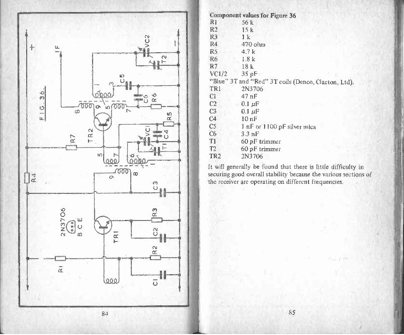
LL
cf)
(9
LL
co
<N1
CC I-
U)
r-aCtS),
U)cc
0'am -
co
wU
M
ot
I
84
Component values for Figure 36RI 56 kR2 15 kR3 1 kR4 470 ohmR5 4.7 kR6 1.8 kR7 18 kVC1/2 35 pF"Blue" 3T and "Red" 3T coils (Denco, Clacton, Ltd).TRI 2N3706Cl 47 nFC2 0.1 ,uFC3 0.1 µFC4 10 nFC5 I nF or 1100 pF silver micaC6 3.3 nFTI 60 pF trimmerT2 60 pF trimmerTR2 2N3706
It will generally be found that there is little difficulty insecuring good overall stability because the various sections ofthe receiver are operating on different frequencies.
85

FM SECTION 3
For 2m mobile working, frequency modulation is largely used,direct or through repeaters activated by an audio tone. These
signals are heard with VHF commercially made portable orother receivers covering 144-146MHz.
FM signals are most readily generated by modulating an 8MHz
or 12MHz crystal oscillator by means of a varicap diode,
multiplier stages giving output in the 2m band.
For 2m mobile and similar work aerials are usually vertical.
Power is generally about 1-10 watts, giving a range of some
miles with a% -wave whip.
The home station having a good communications type receiver
not designed for FM can obtain satisfactory FM reception bytuning slightly off the signal (slope detection) a converterbeing fitted between aerial and receiver so that the latter uses28-30MHz or some other available band as described earlier.
86
Aerials and Additional Circuit Information
AerialsThe purpose of the aerial is, of course, to radiate the signalas effectively as possible. Generally the aerial will be ofreduced efficiency, because it will not be long enough, orhigh enough, to give radiation equal to that of a dipole.Despite this, practical aerials will give satisfactory results.
The length of a half -wave dipole in feet can be found from468/MHz. Thus approximate half -wave lengths for thevarious bands are as follows: 1.8 MHz 260 feet, 3.5 MHz130 feet, 28 MHz 161/2 feet; and 80 inches for 70 MHz, with381/2 inches for 144 MHz.
It is clear that the long aerials are quite impossible in manycircumstances, and even unlikely for the lower frequencieswith a semi -permanent station. This is overcome by using aquarter -wave or even shorter aerial, and by methods ofloading which give an increase in the electrical length ofthe aerial. It will be apparent that these methods apply tobands such as 1.8 MHz, 3.5 MHz, and often 28 MHz, butwould not be necessary in most circumstances with 144 MHz.
For hand-held portable use, the aerial must be a whip fixedto the transmitter. For mobile use, or semi -portable stationssuch as at a caravan, a somewhat larger type of self-supportingaerial can be employed. For fixed semi -portable locations,it may be possible to erect a temporary dipole for 28 MHz, orrandom -length end -fed aerial for the low frequency bands.These will permit much greater ranges to be worked.
In Figure 37, A shows a full-sized dipole aerial, which will givevery good results. For a frequency of 28.5 MHz, the top canbe 16 ft 5 in overall. It can be made from 7/26 or similarflexible wire and three small egg insulators, one being used at
87
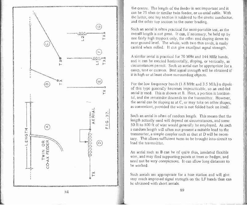
88
the centre. The length of the feeder is not important and itcan be 75 ohm or similar twin feeder, or co -axial cable. Withthe latter, one top section is soldered to the centre conductor,and the other top section to the outer brading.
Such an aerial is often practical for semi -portable use, as theoverall length is not great. It can, if necessary, be held up byone fairly high support only, the other end sloping down tonear ground level. The whole, with two thin cords, is easilycarried when rolled. It can give excellent signal strength.
A similar aerial is practical for 70 MHz and 144 MHz bands,and it can be erected horizontally, sloping, or vertically, ascircumstances permit. Such an aerial can be appropriate for acamp, tent or caravan. Best signal strength will be obtained ifit is high or at least above surrounding objects.
For the low frequency bands (1.8 MHz and 3.5 MHz) a dipoleof this type generally becomes impracticable, so an end -fedaerial is used. This is shown at B. Here, a portion is horizon-tal, and the remainder descends to the transmitter. However,the aerial can be sloping as at C, or may take on other shapes,as convenient, provided the wire is not folded back on itself.
Such an aerial is often of random length. This means that thelength actually used will depend on circumstances, and some50 ft to 100 ft of wire would generally be employed. As sucha random length will often not present a suitable load to thetransmitter, a simple coupler such as that at D will be neces-sary. This allows sufficient turns to be brought into circuit toload the transmitter.
An aerial such as B can be of quite thin, insulated flexiblewire, and may find supporting points at trees or hedges, andneed not be very conspicuous. It can allow long distances tobe worked.
Such aerials are appropriate for a base station and will givevery much improved signal strength on the LF bands than canbe obtained with short aerials.
89

It is worth noting that mobile aerials can be purchased for anyband. These are excellent for LF bands or VHF working whenthey can be fitted to a car or caravan.
For hand-held operation, a telescopic aerial is necessary. Thiscan be represented as at E. For 144 MHz it can be a quarterwave, or more. But for the lower frequencies, the aerial willbe very much shorter in terms of wavelength. For example, at28 MHz it would need to be some 8 ft or so long.
There are several means of using such aerials, which are inthemselves too short for the operating frequency. The aerialcan be used as it is, and can radiate reasonably, providedsuitable coupling allows loading of the transmitter. Or a load-ing coil Ll can be fitted near the base, on the aerial, or in thetransmitter, so that working resembles that obtained with Dand C together. Or the coil can be moved up the aerial, beingL2 at G. This is more efficient than F, as current is moved upthe lower section.
It is clear that considerable experiment can be made with theaerial system. For maximum portability, E or F will beadopted. Aerials of type G are available for the 27 MHz(model control) band, and can be modified for 28 MHz.Arrangements similar to F can be made, when operation is tobe on one of the LF bands.
In some cases it will be convenient to be able to attach a betteraerial when using the equipment at home or when circum-stances permit this. This may extend the range from a few'miles, to a hundred miles or more, according to the band,and conditions.
144 MHz VerticalsA '4 -wave aerial for 144 MHz is about 19 in long and isoperated against earth - the latter often in the form of avehicle or caravan roof. This is shown in Figure 38. A co-axial feeder is used here, with its inner conductor to the baseof the vertical aerial, and outer conductor to earth. If the
90
aerial is of correct length, there will be a smooth flow ofpower along the feeder, with small losses. The feeder isthus a convenient means of allowing the aerial to be situatedto best advantage. Magnetic mounts avoid any need to drillthe roof.In the case of a hand-held transmitter, earth is provided bythe equipment case, and to some extent by the user's body.This is less effective but has to be tolerated.
When the aerial is Y4 -wavelength long, the relationship betweenvoltage and current at its base is such, that the impedance isaround 52 ohms, or sufficiently near for 52 ohm feeders tobe used.
If the aerial is lengthened, to increase radiation, the baseimpedance may change considerably. As example, if it weretwice as long, or a 1/2 -wave, the relationship between currentand voltage is now changed, current being low, and voltagehigh. As a result, the impedance is very high (many hundredsof ohms) and a 52 ohm feeder can no longer be used. But ifthe length of the aerial is even further increased, so that it isabout a 3% -wave in length, the impedance at the base is againlow, allowing a 52 ohm feeder.
91

Where the length is not electrically correct, matching to a52 ohm or similar feeder or output circuit can be arranged bymeans of a loading coil. This fact, and the short physicallength of a Vi -wave or similar aerial at 144 MHz; allows longeraerials to be used without too much difficulty.
In Figure 38, B is an extended aerial with loading coil, whileC is also an extended aerial, this time with a base coil used asa matching device by employing a suitable tapping for thefeeder.
It is possible to use any practical lengths for B or C, providedcoils LI and L2 (and the tap on L2) are adjusted correctly.Correct adjustments can be found by tuning for maximumradiated signal strength; or by using a standing wave ratioindicator in the feeder, and tuning the aerial for lowestreflected power.
For semi -permanent use, a telescopic aerial offers an easymeans of adjusting the aerial length, but for a stronger andweatherproof aerial a solid conductor is preferred. This canbe a metal rod about in in diameter, or very stout self-supporting wire. A light alloy tube can also be used, with itstop pinched shut or plugged. The coils should be of stoutwire - say 14 swg.
A length of 5 ft is suggested for aerial B, and 4 ft for aerial C.LI can then be ten turns spaced over about 11/2 in windinglength, on a VI in diameter insulated rod. L2 can be seven
turns, in in diameter and 1 in long. The tap is two to threeturns from the bottom.
The aerials can be tuned by changing their length, or by alter-ing the coil. The simplest method is to use temporarily a wireof similar gauge to the rod, beginning with it too long, and tocut a little at a time from the end, until radiation is at amaximum and the SWR low. This should be done with theaerial in its intended location. Note results, and finally havethe rod at the length which gives best results.
92
A vertical such as A, or rod alone, is readily supported by astand-off insulator or similar mounting at the bottom. Radi-ation of B and C is best if LI and L2 are vertically in line withthe aerials. It is thus necessary to have a paxolin tube or somesimilar means of providing a support for the bottom of theaerial. This needs to be of sufficient strength to resist windpressure or vibration. Failing this, the coil can be situated atthe feeder side of the mounting, as at D, in the interests ofobtaining a strong fixing for the aerial itself.
Similar arrangements to these are practical for 28 MHz, orindeed for the low frequency bands. However, the aerialitself should then be as long as reasonably practicable, and theloading coil will need to be of larger diameter, and have manymore turns.
With hand-held equipment for 144 MHz, the simplest solutionis to fit a 1/4 -wave in the form of a telescopic aerial cut tocorrect length. However, aerials longer than 1/4 -wave arereadily possible at this frequency, and are often employed toimprove radiation. For hand-held equipment at 28 MHz, G inFigure 37 offers best results with a telescopic aerial, but thecoil is often moved to position F to allow it to be inside thetransmitter. It can be a cored coil similar to that used forcollector tuning. This also applies to the use of hand-heldtransmitting equipment on the lower frequencies.
Pi TankAs operation will be on a single frequency in many cases,with an aerial of particular length, suitable coupling can bearranged from a secondary, closely situated to the finalamplifier collector coil. In order that the amplifier can worksatisfactorily, the aerial must present an approximately suit-able load. This is arranged by using the correct number ofturns on the secondary, and positioning this to achieve propercoupling. With correct coupling, the PA is loaded so that itdraws a suitable collector current, and RF energy is transferredto the aerial, to be radiated.
93
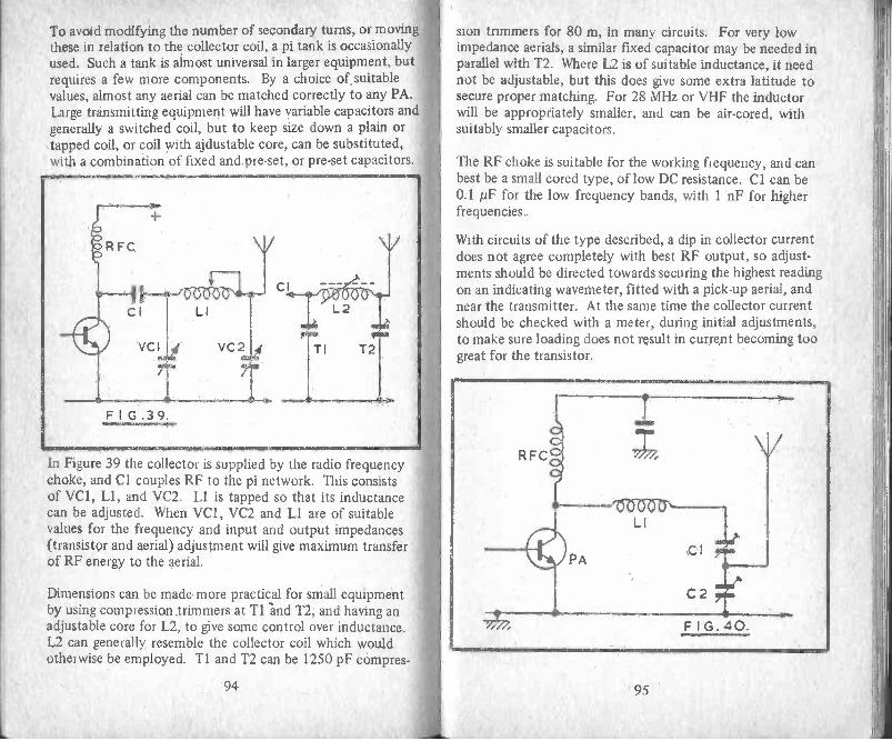
To avoid modifying the number of secondary turns, or moving\these in relation to the collector coil, a pi tank is occasionallyused. Such a tank is almost universal in larger equipment, butrequires a few more components. By a choice of suitablevalues, almost any aerial can be matched correctly to any PA.Large transmitting equipment will have variable capacitors andgenerally a switched coil, but to keep size down a plain ortapped coil, or coil with ajdustable core, can be substituted,with a combination of fixed and pre-set, or pre-set capacitors.
F I G .3 9
In Figure 39 the collector is supplied by the radio frequencychoke, and Cl couples RF to the pi network. This consistsof VC1, Ll, and VC2. LI is tapped so that its inductancecan be adjusted. When VC1, VC2 and LI are of suitablevalues for the frequency and input and output impedances(transistor and aerial) adjustment will give maximum transferof RF energy to the aerial.
Dimensions can be made more practical for small equipmentby using compression trimmers at Ti and T2, and having anadjustable core for L2, to give some control over inductance.L2 can generally resemble the collector coil which wouldotherwise be employed. T1 and T2 can be 1250 pF compres-
94
sion trimmers for 80 m, in many circuits. For very lowimpedance aerials, a similar fixed capacitor may be needed inparallel with T2. Where L2 is of suitable inductance, it neednot be adjustable, but this does give some extra latitude tosecure proper matching. For 28 MHz or VHF the inductorwill be appropriately smaller, and can be air -cored, withsuitably smaller capacitors.
The RF choke is suitable for the working frequency, and canbest be a small cored type, of low DC resistance. Cl can be0.1 itiF for the low frequency bands, with 1 nF for higherfrequencies.
With circuits of the type described, a dip in collector currentdoes not agree completely with best RF output, so adjust-ments should be directed towards securing the highest readingon an indicating wavemeter, fitted with a pick-up aerial, andnear the transmitter. At the same time the collector currentshould be checked with a meter, during initial adjustments,to make sure loading does not result in current becoming toogreat for the transistor.
95

Capacitor LoadingFigure 40 is a circuit which may be used to allow adjustmentof loading by the aerial. If the power amplifier transistor isto draw correct current from the battery and deliver this asradiated energy from the aerial, some form of impedancematching is required. Here, Cl and C2 are an alternative tousing a coupling winding in conjunction with the coil LI.
The RF choke needs to be of low DC resistance, and must besuitable for the working frequency. For 144 MHz, it can betwenty-five turns of 28 swg enamelled wire, on an insulatedformer about 5 mm in diameter. LI can be five turns of 18swg wire, 6 mm inside diameter and with turns spaced tooccupy 12 mm. Cl can be 25 pF and C2 60 pF.
The capacitances Cl and C2 in series resonate the circuit, butsetting C2 to a lower value and increasing the capacitance ofCI has the effect of moving the aerial coupling point nearerto LI. To adjust this circuit, begin with C2 at fairly highcapacitance, and tune LI to resonance by C1. Resonance isshown by an indicating wavemeter, or by a suitable bulbreplacing the aerial, as explained. A lamp load will be fromthe junction of CI /C2 to negative or ground line. With
tuning for maximum output by means of Cl , slightly change!the setting of C2, re -adjusting Cl for maximum output. Ifthis is greater than before, repeat adjustments in the samedirection. Continue this until RF output is at maximum,but note that the DC input to the PA is not taken beyondthe safe level.
A similar circuit can also be used between stages, with driveto the base of a following transistor from the junction of Cland C2. One or both capacitors may be fixed, with LFcircuits. See Figure 18.
Further CircuitsThe circuit information in this section should prove to be ofinterest, and will assist in the construction of equipment ofthe general type described. Tuning up and initial testing willbe on the lines already described in detail.
96
Simple TalkieThe selection of transmitter and receiver circuits from thosegiven will depend on the frequency required, and the eventualsize, weight, and complication of the finished equipment.Where a pair of low power units are to be used for two waycommunication, the receivers incorporated need to be of goodsensitivity. Where communication is to be between a hand-held unit and a higher power station, the talkie receiver canbe of a simpler type. Lower transmitter power will also bepossible when one station has a highly sensitive communica-tions type receiver.
A good set of equipment can be made from a transmittersection running 300 mW to 500 mW or so, with a crystalcontrolled superhet receiver. On the other hand, equipmentcan be cut down considerably when a more modest per-formance is sufficient, and Figure 41 shows the circuitryfor a small talkie somewhat similar to low priced commer-cially made equipment.
TR1 is the power amplifier, driven by Ll, and is thus thesecond transistor in an oscillator/amplifier arrangement ofthe type already covered in detail. LI and L2 will be tunedto the chosen band. Here, 2,r8idliz is sqggested,
TR2 is an audio amplifier, driven by the loudspeaker, whichserves as a microphone for transmission purposes. TR2 shouldbe a high gain amplifier, with hfe of 400 or higher (theBC109 is typical). If necessary, RI or R2 (or both) may beadjusted in value to secure optimum gain. This stage isdecoupled by C3 and R4, and coupled to TR3 by C2.
TR3 is the series modulator for TR1. By using the NPN typeof transistor, gain is substantially higher than with the circuitin Figure 15, but operating conditions are more critical. Apre-set resistor to adjust base bias (and hence the relativevoltages across TR1 and TR3) is essential. Begin with VR1set at low value, increasing this until the voltage availablefrom the supply is approximately equally divided across TR1and TR3, with TR1 loaded and tuned. R5 is an audio para-
97

-J
[-tsccc-
Q.S20,(;)'
((NM
C-2cc
NLL.
6 3-
cc
C
N
+
ct
98
(.9
sitic stopper, and is of the lowest value found adequate (220ohm or less). Since the supply voltage is not fully availablefor TR1, a 12V battery pack is best. For best performance,aerial loading, tuning of LI and L2, VR1, and volume ofspeech into the microphone (loudspeaker) all have to beadjusted.
The simplest receiver for 28 MHz will be seen in Figures 24and 25, followed by a two-stage audio amplifier, Figure 32.This allows the speaker unit to be returned to the negativeline, so that a single switch can transfer this item fromreceiver output at S to Cl for operation as a microphone.A further switch pole takes the aerial to receiver aerial inputat AE, or to the secondary of L2. Another pole switches ontransmitter and receiver sections. The final pole shows howRF may be kept out of the receiver first stage by shortingthe receiver input, to protect the RF transistor whenrequired. A 3 -way switch allows a central "off" position.
Instability and similar troubles are unlikely during reception.With the transmitter circuits, the most likely cause ofdifficulty can be feedback of RF into the first audio stage.Layout and switching must be arranged to avoid this. Suchfeedback is usually heard either as a continuous whistle orhowl accompanying transmission, or as spurious soundsaccompanying speech. However, the latter can also be verysevere overmodulation, and with TR3 having substantial gain(say hfe of 250, or typically a BC108) loud speech near themicrophone is not necessary. If necessary, capacitors of about470 pF to 1 nF from TR2 base or TR3 base to negative linewill help keep RF out of these stages.
Super -regenerationFigure 42 is a further super -regenerative detector circuit.Cx is a very small capacitance, and can be made by twistingtogether two insulated wires for about Y4 in of their length.Alternatively, a coupling winding could be used. Values areprimarily for 144 MHz but the circuit can be used on 28 MHz.Coil details will be found in the information provided with
99

earlier circuits. The value of VC1 can be modified to obtainthe wanted coverage, or may consist of pre-set and variable
capacitors in parallel.
C3 4.7PF TI
VCI IOPF
R3t--{ I
100KRI10K
FIG. 42.
R2 IK
TRI
C22NF C4
0.1pFT
- VRI50K
Regeneration is controlled by VR1. Numerous transistortypes will operate with this circuit, and the value of C3 maybe changed if necessary to secure satisfactory regeneration.
Tl is a coupling transformer, to drive the base circuit of thefirst audio amplifier. Resistance capacitor coupling can beused here instead. The operation of this circuit and its adjust-ment will be similar to that of the super -regenerative detectorshown in Figure 24.
Carbon MicrophoneFor some equipment the use of a carbon microphone willallow simplification of the audio amplifier. Such a micro-phone can give a relatively large audio signal, so that reducedamplification is sufficient. A carbon microphone does notproduce any audio output voltage itself, but is a device whoseresistance varies at audio frequency. It is thus necessary to
100
pass a direct current through the microphone. This can bedone by using a microphone transformer. This is a compon-ent with a step-up ratio of about 1:50 to 1:100. The carbonmicrophone, transformer primary, and a source of DC (about1.5V to 4.5V) are connected in series. A very large audiosignal voltage is obtained from the transformer secondary.
An alternative circuit which avoids the need for a transformeris shown in Figure 43. Direct current for the carbon micro-phone is obtained through RI. The audio signal at Cl isamplified in the usual way. R2, R3 and C2 can be typicalfor the stage - Cl and C2 may be 0.1 /IF, with a 1.8 megohmfor R2, and 10 k for R3.
RI is best chosen so that optimum microphone current isprovided. About 100 ohm is generally suitable. Unnecessarilylow values here will increase battery drain, and tend to causenoise. C3 and R4 will only be necessary where audio fluctu-ations in battery supply cause feedback of other troubles,and R4 can typically be a few hundred ohms, with 220µFto 640 µF for C3.
StabilisationWith a pair of transistors in a push-pull modulator (or
101
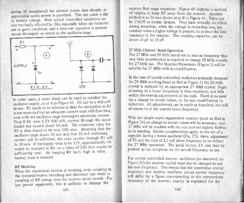
similar IC modulator) the current drawn rises sharply as
appreciable audio power is provided. This can cause a dip
in battery voltage. Most crystal controlled oscillators are
not too badly affected by this, especially when the batteries
are in good condition, and a reservoir capacitor is presentacross the supply or circuit to the oscillator stage.
In other cases, a zener diode can be used to stabilise theoscillator supply, as at A in Figure 44. Dl can be a 400 mW
device. R1 needs to be selected so that the dissipation in D1
is not exceeded but an adequate current must still flow here,
even with the oscillator stage drawing its maximum current.
Thus if D1 were 6.2V 400 mW, current through the diodeshould not exceed about 60 mA. The minimum value for
RI is then found to be near 100 ohm. Assuming that theoscillator stage draws 20 mA and that 10 mA stabilisingcurrent will be sufficient, the total current through RI willbe 30 mA. If the supply were to be 12V, approximately 6Vwould be dropped in R1, so a value of 220 ohm would be
sufficiently near. By keeping RI fairly high in value,
battery drain is reduced.
RF BlockingWhen the transmitter section is working, stray coupling in
the transmit/receive switching and elsewhere can result in
coupling of RF energy into the receiver aerial circuit. For
low power equipment, this is unlikely to damage the
102
receiver first stage transistor. Figure 41 includes a methodof helping to keep RF away from the receiver. Anothermethod is to fit two diodes as at B in Figure 44. There canbe 1N629 or similar devices. They have virtually no effectduring reception, when the voltage is exceeding low, butconduct when a higher voltage is present, to protect the' firsttransistor in the receiver. The coupling capacitor can' beabout 10 pF to 18 pF.
27 MHz Citizens' Band OperationThe 27 MHz and 28 MHz bands are so near in frequency thatvery little modification is required to change 28 MHz circuitsfor 27 MHz use. The Monitor/Wavemeter (Figure 3) will besuitable for 27 MHz with no modification.
In the case of crystal controlled oscillators primarily designedfor 28 MHz working (such as that in Figure 5) the 28 MHzcrystal is replaced by an appropriate 27 MHz crystal. Slightre -tuning to a lower frequency is then necessary, and fallswithin the normal adjustments of the coils. There is no needfor a change to circuit values, or for any modification toinductors. All adjustments can be made as described, but willof course be at the wanted lower frequency.
With the simple super -regenerative receiver (such as that inFigure 24) no change to circuit values will be necessary, and27 MHz will be reached with the coil core set slightly furtherin its winding. Similar considerations apply to the use of asuperhet having a tuned oscillator (Fig. 27). Here, adjustmentof T1 and the core of L2 will allow frequency to be shiftedfor 27 MI-Iz operation. The aerial circuit, LI, can then bepeaked up for reception on the actual frequency in use.
For crystal controlled receiver oscillators (as described forFigure 30) the receiver crystal must also be changed to suitthe new frequency. This means that the transmitter crystalfrequency and receiver oscillator circuit crystal frequencywill differ by a figure corresponding to the intermediatefrequency of the receiver, exactly as explained for the
'103

28 MHz band. Thus, for 27 MHz, the receiver crystal can
be 27,465 kHz, or 26,535kHz (27.465 MHz or 26.535 MHz)where the receiver IF is 465 kHz, and according to whether
the oscillator is to operate at the high frequency or lowfrequency side of the transmission frequency. Where the
receiver IF is 470 kHz or some other frequency, the receiveroscillator crystal is chosen to suit, as explained.
In the case of aerials, the approximate length of a half wave
can be found from 468/MHz, the result being in feet. As
example, this is about 17.33 ft for 27 MHz and 16.7 ft for28 MHz. It will be seen that these are quite close to each other
and a result of this is that adjustable whip and similar systems
can generally be tuned from 28 MHz to 27 MHz with little
difficulty. The 27 MHz aerial will need to be a little longer,
or its loading inductance will have to be slightly greater.
As mentioned earlier in relation to Amateur activities inGreat Britain, reference should be made to the appropriate
local authority regarding conditions of operation.
104
Notes

Notes OTHER BOOKS AVAILABLE BY THE SAME AUTHOR
BP30: TWO TRANSISTOR ELECTRONIC PROJECTSISBN: 0 85934 033 3 Price: 85pApprox. Size: 180 x 105 mm 96 PagesThis book is written by Mr F.G. Rayer, a very experienced andpopular author, who has written many books and contributesregularly to the monthly electronic magazines. It covers 28popular projects that can be built using only two transistors.Mr Rayer initially describes in detail the various methods ofconstruction, Tag Board, Veroboard, or printed circuit andthen carefully details the various projects to be constructed.An ideal book for beginners and more advanced enthusiastsalike.
BP32: HOW TO BUILD YOUR OWN METAL ANDTREASURE LOCATORSISBN. 0 85934 035 X Price: 85pApprox. Size: 180 x 105 mm 96 PagesThis book contains complete electronic and practical detailson the simple and inexpensive construction of HeterodyneMetal Locators. This is one of the most fascinating applica-tions of electronics and an ideal book to capture the interestof the beginner, also just as applicable to the more advancedenthusiast.
BP35: HANDBOOK OF IC AUDIO PREAMPLIFER ANDPOWER AMPLIFIER CONSTRUCTIONISBN: 0 85934 038 4 Price: 95pApprox. Size: 180 x 105 mm 112 PagesThis book is divided into three parts: Part I, understandingaudio IC's, Part II, Preamplifiers, Mixers and Tone Controls,Part III, Power Amplifiers and Supplies. Includes practicalconstructional details of pure IC and Hybrid IC and Transistordesigns from about 250 mW to 100 W output. A "must" forthe library of both beginner and experienced enthusiast alike.
BP37: 50 PROJECTS USING RELAYS, SCRs and TRIACs
ISBN: 0 85934 040 6 Price: £1.10Approx. Size: 180 x 105 mm 112 Pages
Relays, silicon controlled rectifiers (SCRs) and bi-
directional triodes (TRIACs) have a wide range of applicationin electronics today. These may extend over the whole fieldof motor control; dimming and heating control; delayed,timing and light sensitive circuits and include warning devices,various novelties, light modulators, priority indicators, excess
voltage breakers, etc.This book gives tried and practical working circuits which
should present the minimum of difficulty for the enthusiast
to construct. In most of the circuits there is a wide latitude
in component values and types, allowing easy modification
of circuits or ready adaption of them to individual needs.
An ideal book for both beginner and advanced enthusiast
alike.
BP39: 50 (FET) FIELD EFFECT TRANSISTOR PROJECTS
ISBN: 0 85934 042 2 Price: £1.25
Approx. Size: 180 x 105 mm 112 Pages
Field effect transistors (FETs) find application in a wide
variety of circuits. The projects described here include radio
frequency amplifiers and converters, test equipment andreceiver aids, tuners, receivers, mixers and tone controls, aswell as various miscellaneous devices which are useful in the
home.It will be found that in general the actual FET used is not
critical and many suitable types will perform satisfactorily.The FET is a low -noise, high gain device with many uses, andthe dual gate FET is of particular use for mixer and other
applications.This book contains something of particular interest for
every class of enthusiast - shortwave listener, radio amateur,experimenter or audio devotee.
A valuable addition to the library of all electronic
enthusiasts.
Please note overleaf is a list of other titles that are available inour range of Radio and Electronic Books.
These should be available from most good Booksellers,Radio Component Dealers and Mail Order Companies.
However, should you experience difficulty in obtaining anytitle in your area, then please write directly to the publishersenclosing payment to cover the cost of the book plus adequatepostage.
BABANI PRESS & BERNARDS (PUBLISHERS) LTDTHE GRAMPIANS
SHEPHERDS BUSH ROADLONDON W6 7NF
ENGLAND

BP1 First Book of Transistor EquIvalents and Substitutes 60p
BP2 Handbook of Radio, N and Ind. & Transmitting Tube & valve EquN. 60p
BP6 Engineers and Machinists Reference Tables 50p
BP7 Radio and Electronic C0101.11 Codes and Data Chart 25p
BP11 Practical Transistor Novehy Circuits 40p
BP14 Second Book of Transistor Equivalents 1,10p
BP22 79 Electronic Novelty Circuits75p
BP23 First Book of Practical Electronic Projects 75p
BP24 52 Projects using IC74195p
BP25 How to Build Your Own Electronic and Quartz Controlled Watches & Clocks 85p
BP26 Radio Antenna Handbook for Long Distance Reception & Transmission 85p
13P27 Giant Chart of Radio Electronic Semiconductor & Logic Symbols 60p
BP28 Resistor Selection Handbook (international Edition) 60p
BP29 Major Solid State Audio Hi-Fi Construction Projects 85p
BP30 Two Transistor Electronic Projects85p
BP31 Practical Electrical Re -wiring & Repairs 85p
BP32 How to Build Your Own Metal and Treasure Locators 1.00p
BP33 Electronic Calculator Users Handbook 95p
BP34 Practical Repair & Renovation of Colour Na' 95p
BP35 Handbook of IC Audio Prearnpfrfier & Power Amplifier Construction 1.25p
BP36 50 Circuits Using Germanium, Silicon and Zener Diodes 75p
BP37 50 Projects Using Relays, SCR's and TRIAC's1.10p
BP38 Fun & Games with your Electronic Calculator75p
BP39 50 (FET) Field Effect Trarisistor Projects 1.25p
BP40 Digital IC Equivalents and Pin Connections2.50p
BP41 Linear IC Equivalents and Pin Connections 2.75p
BP42 50 Simple L.E.D. Circuits 75p
BP43 How to make Walkie-Talkies 1.25p
BP44 IC 555 Projects1.45p
BP45 Projects on Opto-Electronics1.25p
BP46 Radio Circuits using IC's 1.35p
BP47 Mobile Discotheque Handbook1.35p
BP48 Electronic Projects for Beginners1.35p
BP49 Popular Electronic Projects1.45p
BP50 IC LM3900 Projects1.35p
BP51 Electronic Music and Creative Tape Recording 1.25p
BP52 Long Distance Television Reception (TV -DX) for the Enthusiast 1.45p
BP53 Practical Electronic Calculations and Formulae 2.25p
BP54 Your Electronic Calculator and Your Money 1.35p
BP55 Radio Stations Guide 1.45p
BP56 Electronic Security Devices1.45p
BP57 How to Build your own Solid State Oscilloscope1.500
ESP59 50 Circuits using 7400 Series IC's1.35p
I3P59 Second Book of CMOS IC Protects 1.50p
BP60 Practical Construction of Pm -Amps. Tone Controls, Filters and Attenuators 1.45p
BP61 Beginners Guide to Digital Techniques95p
100 A Comprehensive Redo Valve Guide - Book 1 40p
121 A Comprehensive Radio Valve Guide - Book 2 40p
126 Boys Book of Crystal Sets 25p
138 How to Make Aerials for TV (Band 1-2-3) 25p
143 A Comprehensive Radio Valve Guide - Book 3 40p
157 A Comprehensive Radio Valve Guide - Book 4 40p
160 Coil Design and Construction Manuel 75p
178 A Comprehensive Radio Valve Glide - Book 5 40p
196 AF-RF Reactance - Frequency Chart for Constrictors 15p
200 Hartibutik of Practical Electronic Musical Novelties 50p
201 Practical Transistorised Novelties for HI -Fl Enthusiasts 35o
202 Handbook of Integrated Circuits (IC's) Equivalents and Substitutes 1.000
203 IC's and Transistor Gedgets Construction Handbook 60p
205 First Book of HI -F1 Loudspeaker Enclosures 75p
206 Practical Transistor Circuits for Modern Test Equipment 60p
207 Practical Electronic Science Projects 75p
208 Practical Stereo and Ouadrophony Handbook 75p
210 The Complete Car Radio Manual 1.00p
211 First Book of Diode Characteristics Equivalents and Substitutes 95p
213 Electronic Circuits for Model Railways 1.00p
214 Audio Enthusiasts Handbook85p
215 Shortwave Circuits and Gear for Experimenters and Radio Hams 85p
216 Electronic Gadgets and Games1.00p
217 Solid State Power Supply Handbook85p
218 Build Your Own Electronic Experimenters Laboratory 85p
219 Solid State Novelty Projects85p
220 Build Your Own Solid State HI -Fl and Audio Accessories 85p
221 28 Tested Transistor Projects95p
222 Sold State Short Wave Receivers for Beginners 95p
223 50 Projects using IC CA313095p
224 50 CMOS IC Projects95p
225 A Practical Introduction to Digital IC's 95p
228 How to Build Advanced Short Wave Receivers 120p
227 Beginners Guide to Building Electronic Projects1.25p
228 Essential Theory for the Electronics Hobbyist 125p
RCC Resistor Cola,, Code Disc Calculator10p

How to MakeWalkie-Talkies
Equipment for low power hand-held orportable operation need not be of a verycomplicated ii/pe to give excellent results andit falls more readily in the scope of the homeconstructor than does, say, medium or highpowered transmitters and multi -band receivers.
In This bOok, the very experienced authorMr. F. G. Rayer, G3OGR, presents an excellenttreatise on Low Power Transmitter -Receivers or'Walk ie-Talkies' as they are more popularlycalled, covering many aspects from licensingrequirements and bands, through practical.
circuitry and construction to the various typesof aerials`that may be used.
Divided intothree sections:ITrarSmission
IIReceptionIIIAerials and Additional
Circuit .Information.
A book of great interest not only to thelicenced operator, but also to those enthusiastswithout transmitting licences who can participateas.listene'rs with the receiver equipmentdescribed.
BABANI PRES8The GrampiansShepherds Bush RoadLondon W6 7NFEnglandI"
ISBN 0 85934 046 5