WA LL M OUNTED type - fujiklimatizace.cz · AIR CIRCULATION-Hi (m3/hr) C 630 H665 C 630 H700...
17
SPLIT TYPE ROOM AIR CONDITIONER WALL MOUNTED type Models Indoor unit Outdoor unit RS-9LA RS-12LA RO-9LA RO-12LA C O N T E N T S SPECIFICATIONS . . . . . . . . . . . . . . . . . . . . . . DIMENSIONS . . . . . . . . . . . . . . . . . . . . . . . . . . REFRIGERANT SYSTEM DIAGRAM . . . . CIRCUIT DIAGRAM . . . . . . . . . . . . . . . . . . . . DISASSEMBLY ILLUSTRATION . . . . . . . . PCB CIRCUIT DIAGRAM . . . . . . . . . . . . . . PARTS LIST . . . . . . . . . . . . . . . . . . . . . . . . . . 1 3 4 5 8 ERROR CONTENTS . . . . . . . . . . . . . . . . . . . 6 10 13 STANDARD ACCESSORIES . . . . . . . . . . . 15
Transcript of WA LL M OUNTED type - fujiklimatizace.cz · AIR CIRCULATION-Hi (m3/hr) C 630 H665 C 630 H700...

S PLIT T Y PE R OOM A IRCON DIT ION E R
WA L L M O U N T E D t y pe
Models Indoor unit Outdoor unit
RS-9LA
RS-12LA
RO-9LA
RO-12LA
C O N T E N T S
SPECIFICATIONS . . . . . . . . . . . . . . . . . . . . . .
DIMENSIONS . . . . . . . . . . . . . . . . . . . . . . . . . .
REFRIGERANT SYSTEM DIAGRAM . . . .
CIRCUIT DIAGRAM . . . . . . . . . . . . . . . . . . . .
DISASSEMBLY ILLUSTRATION . . . . . . . .
PCB CIRCUIT DIAGRAM . . . . . . . . . . . . . .
PARTS LIST . . . . . . . . . . . . . . . . . . . . . . . . . .
1
3
4
5
8
ERROR CONTENTS . . . . . . . . . . . . . . . . . . . 6
10
13
STANDARD ACCESSORIES . . . . . . . . . . . 15

S P E C I F I C A T I O N S
T Y PE (COOL& HE A T IN V E R T E R ) (COOL& HE A T IN V E R T E R )
IN DOOR U N IT R S -9LA R S -12LA
OU T DOOR U N IT R O-9LA R O-12LA
COOLIN G CA PA CIT Y ( ) : R ange (kW ) 2.6(0.5~3.6) 3.5(0.9~4.2)
HE AT IN G CA PA CIT Y ( ) : R ange (kW ) 3.6(0.5~6.0) 4.8(0.9~6.6)
POW E R S OU R CE (V ) 230
FR E QU E N CY (Hz) 50
R U N N IN G CU R R E N T (A )COOLIN G 3.0
3.6 5.8
1.33(0.25~2.30)0.91(0.25~1.96)
4.6
HE AT IN G
IN PU T WAT T S (kW )COOLIN G 0.68(0.25~1.38) 1.03(0.25~1.61)
HE AT IN G
E E R (kW /kW )COOLIN G 3.82 3.40
3.96 3.61
1.8
HE AT IN G
M OIS T U R E R E M OVA L (r /hr) 1.3
A IR CIR CU LAT ION -Hi (m 3/hr) C 630 H665 C 630 H700
E LE CT R ICA L DATA
COM PR E S S OR
Note : Always use a vacuum pump to purge the air.
Refrigerant for purging the air is not charged in the outdoor unit at the factory.
DIM E N S ION S
T Y PE Herm etic type,
4 pole, 3 phase , DC brushles m otor
CODE 80206680
R E FR IG E R A N T R 410A (g) 950 1100
POW E R S OU R CE (V ) 230 230
HI-S PE E D (r.p.m .) C 1,350 H1,420 C 1,400 H1,470
M E D-S PE E D (r.p.m .) C 1,150 H1,200 C 1,200, H1,290
IN DOOR U N IT
LO-S PE E D (r.p.m .) C 950 H1,000 C 1,000 H1,110
QU IE T (r.p.m .) C 740 H900 C 820 H9801, 1, 1,
OU T DOOR U N IT (r.p.m .) 830 830
IN DOOR U N ITH x W x D (m m )
280 x 790x 230
OU T DOOR U N IT 535 x 780 x 250
FA N M OT OR
80206680
2003.06.09 1
HI-S PE E D (dB ) C 42 H 42 C 43 H 43
M E D-S PE E D (dB ) C 37 H 36 C 39 H38
IN DOOR U N IT
LO-S PE E D (dB ) C 31 H 30 C 32 H 33
QU IE T (dB ) C 23 H 26 C 26 H 29
OU T DOOR U N IT (dB ) C 47 H 49 C 47 H 49
N OIS E LE V E L
Note : Noise was measured in accordance with JIS standards, Japan.
W E IG HT S
IN DOOR U N ITG R OS S / N E T (kg)
12 / 9
OU T DOOR U N IT 35 / 33 37 / 34
PIPE LE N G T H 7.5 m 10 m
A DDIT ION A L R E FR IG E R A N T N one N one
15 m
N one
2003.06.09 2
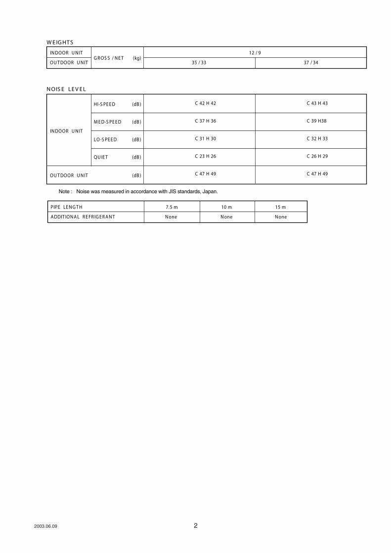
D I M E N S I O N S
Models : RS-9LA / RO-9LA
2003.06.09
RS-12LA / RO-12LA
3
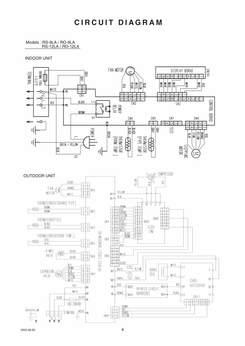
C I R C U I T D I A G R A M
INDOOR UNIT
OUTDOOR UNIT
Models : RS-9LA / RO-9LA
RS-12LA / RO-12LA
2003.06.09 4

R E F R I G E R A N T S Y S T E M D I A G R A M
Models : RS-9LA / RO-9LA
RS-12LA / RO-12LA
2003.06.09 5
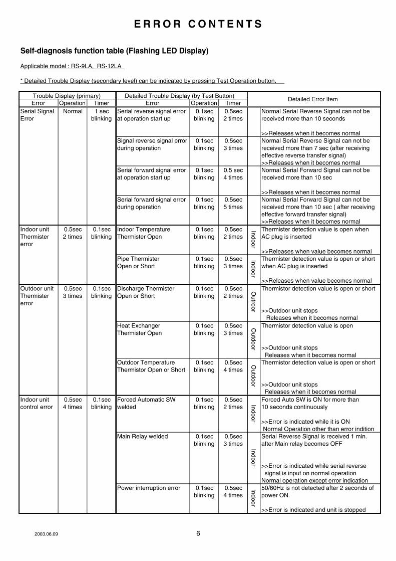
Self-diagnosis function table (Flashing LED Display)
Applicable model : RS-9LA, RS-12LA
* Detailed Trouble Display (secondary level) can be indicated by pressing Test Operation button.
Error Operation Timer Error Operation Timer
Serial Signal Normal 1 sec Serial reverse signal error 0.1sec 0.5sec Normal Serial Reverse Signal can not be
Error blinking at operation start up blinking 2 times received more than 10 seconds
>>Releases when it becomes normal
Signal reverse signal error 0.1sec 0.5sec Normal Serial Reverse Signal can not be
during operation blinking 3 times received more than 7 sec (after receiving
effective reverse transfer signal)
>>Releases when it becomes normal
Serial forward signal error 0.1sec 0.5 sec Normal Serial Forward Signal can not be
at operation start up blinking 4 times received more than 10 sec
>>Releases when it becomes normal
Serial forward signal error 0.1sec 0.5sec Normal Serial Forward Signal can not be
during operation blinking 5 times received more than 10 sec ( after receiving
effective forward transfer signal)
>>Releases when it becomes normal
Indoor unit 0.5sec 0.1sec Indoor Temperature 0.1sec 0.5sec Thermister detection value is open when
Thermister 2 times blinking Thermister Open blinking 2 times AC plug is inserted
error
>>Releases when value becomes normal
Pipe Thermister 0.1sec 0.5sec Thermister detection value is open or short
Open or Short blinking 3 times when AC plug is inserted
>>Releases when value becomes normal
Outdoor unit 0.5sec 0.1sec Discharge Thermister 0.1sec 0.5sec Thermistor detection value is open or short
Thermister 3 times blinking Open or Short blinking 2 times
error
>>Outdoor unit stops
Releases when it becomes normal
Heat Exchanger 0.1sec 0.5sec Thermistor detection value is open
Thermister Open blinking 3 times
>>Outdoor unit stops
Releases when it becomes normal
Outdoor Temperature 0.1sec 0.5sec Thermistor detection value is open or short
Thermistor Open or Short blinking 4 times
>>Outdoor unit stops
Releases when it becomes normal
Indoor unit 0.5sec 0.1sec Forced Automatic SW 0.1sec 0.5sec Forced Auto SW is ON for more than
control error 4 times blinking welded blinking 2 times 10 seconds continuously
>>Error is indicated while it is ON
Normal Operation other than error indition
Main Relay welded 0.1sec 0.5sec Serial Reverse Signal is received 1 min.
blinking 3 times after Main relay becomes OFF
>>Error is indicated while serial reverse
signal is input on normal operation
Normal operation except error indication
Power interruption error 0.1sec 0.5sec 50/60Hz is not detected after 2 seconds of
blinking 4 times power ON.
>>Error is indicated and unit is stopped
Trouble Display (primary) Detailed Trouble Display (by Test Button)Detailed Error Item
Ind
oo
rIn
do
or
Ind
oo
rO
utro
or
Ou
tdo
or
Ou
tdo
or
Ind
oo
rIn
do
or
E R R O R C O N T E N T S
2003.06.09 6
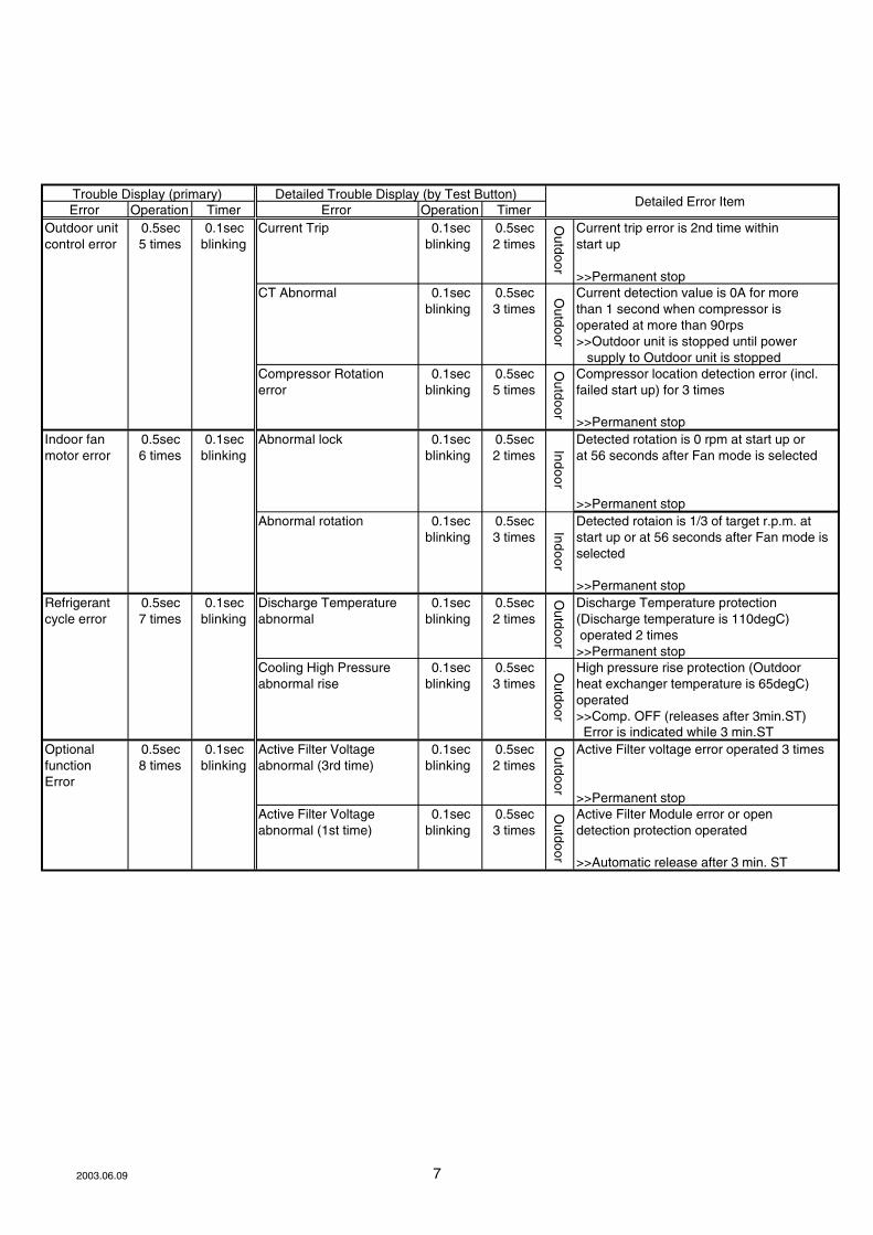
Error Operation Timer Error Operation Timer
Outdoor unit 0.5sec 0.1sec Current Trip 0.1sec 0.5sec Current trip error is 2nd time within
control error 5 times blinking blinking 2 times start up
>>Permanent stop
CT Abnormal 0.1sec 0.5sec Current detection value is 0A for more
blinking 3 times than 1 second when compressor is
operated at more than 90rps
>>Outdoor unit is stopped until power
supply to Outdoor unit is stopped
Compressor Rotation 0.1sec 0.5sec Compressor location detection error (incl.
error blinking 5 times failed start up) for 3 times
>>Permanent stop
Indoor fan 0.5sec 0.1sec Abnormal lock 0.1sec 0.5sec Detected rotation is 0 rpm at start up or
motor error 6 times blinking blinking 2 times at 56 seconds after Fan mode is selected
>>Permanent stop
Abnormal rotation 0.1sec 0.5sec Detected rotaion is 1/3 of target r.p.m. at
blinking 3 times start up or at 56 seconds after Fan mode is
selected
>>Permanent stop
Refrigerant 0.5sec 0.1sec Discharge Temperature 0.1sec 0.5sec Discharge Temperature protection
cycle error 7 times blinking abnormal blinking 2 times (Discharge temperature is 110degC)
operated 2 times
>>Permanent stop
Cooling High Pressure 0.1sec 0.5sec High pressure rise protection (Outdoor
abnormal rise blinking 3 times heat exchanger temperature is 65degC)
operated
>>Comp. OFF (releases after 3min.ST)
Error is indicated while 3 min.ST
Optional 0.5sec 0.1sec Active Filter Voltage 0.1sec 0.5sec Active Filter voltage error operated 3 times
function 8 times blinking abnormal (3rd time) blinking 2 times
Error
>>Permanent stop
Active Filter Voltage 0.1sec 0.5sec Active Filter Module error or open
abnormal (1st time) blinking 3 times detection protection operated
>>Automatic release after 3 min. ST
Trouble Display (primary) Detailed Trouble Display (by Test Button)
Ou
tdo
or
Ind
oo
rO
utd
oo
rO
utd
oo
r
Detailed Error Item
Ou
tdo
or
Ou
tdo
or
Ind
oo
rO
utd
oo
rO
utd
oo
r
2003.06.09 7

RO
OM
TE
MP
ER
AT
UR
E T
HE
RM
IST
OR
PIP
E T
EM
PE
RAT
UR
E T
HE
RM
IST
OR
BL
AC
K
BL
AC
K
GR
AY
GR
AY
RE
D
WH
ITE
LO
UV
ER
RE
D
OR
AN
GE
YE
LL
OW
PIN
K
BL
UE
RE
D
BL
AC
K
BL
UE
YE
LL
OW
WH
ITE
FA
N M
OT
OR
AU
TO
RE
STA
RT
RE
MO
TE
CO
NT
RO
L
CU
ST
OM
C
OD
E
GR
EE
N
GREEN
TE
RM
INA
L B
OA
RD
BL
UE
RED
WHITE
BROWNB
LA
CK
GRAY
GRAY
TH
ER
MA
L F
US
E
WH
ITE
WH
ITE
WH
ITE
WH
ITE
WH
ITE
PO
WE
R S
OU
RC
E2
20
/ 2
40
V5
0H
z
GR
EE
N /
YE
LL
OW
IND
ICAT
OR
PC
B
EZ
-00219H
SE
-D (
F)
I C
1u
PD
78
00
24
SG
B-X
09
CO
NT
RO
LLE
R P
CB
AS
EM
BLY
(M
AIN
PC
B)
AS
Y9LS
AC
W : E
Z-0
0219H
SE
-C
AS
Y12LS
AC
W : E
Z-0
021C
HS
E-C
IND
OO
R P
RIN
TE
D C
IRC
UIT
BO
AR
D
CIR
CU
IT D
IAG
RA
M
82
00
3.0
6.1
0
MB
90
46
2-1
17
N2
00
50
0K
SC
-10
-55
JH
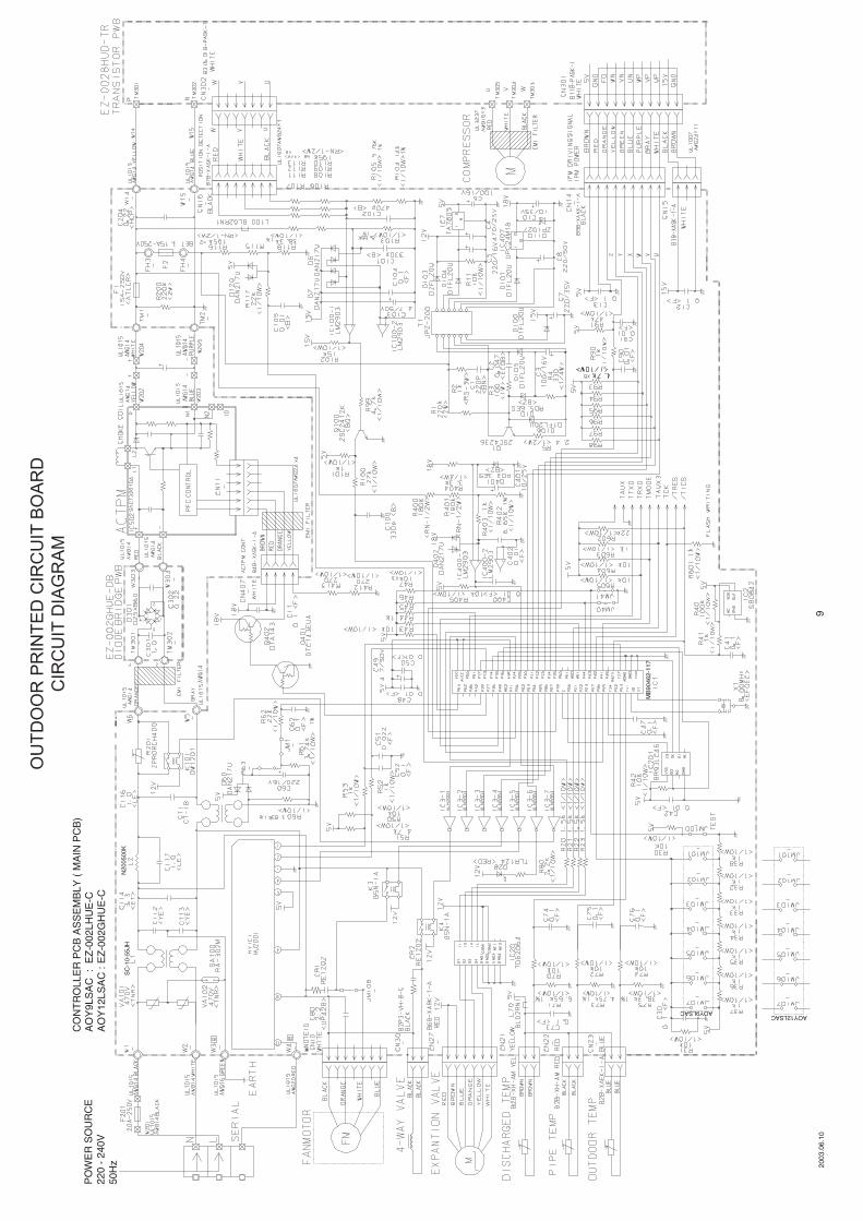
PO
WE
R S
OU
RC
E
220 -
240V
50H
z
AOY12LSACAOY9LSAC
CO
NT
RO
LLE
R P
CB
AS
SE
MB
LY
( M
AIN
PC
B)
AO
Y9LS
AC
: E
Z-0
02LH
UE
-C
AO
Y12LS
AC
: E
Z-0
02G
HU
E-C
OU
TD
OO
R P
RIN
TE
D C
IRC
UIT
BO
AR
D
CIR
CU
IT D
IAG
RA
M
92
00
3.0
6.1
0

2003.06.09 10
D I S A S S E M B LY I L L U S T R AT I O N
Models :
RS-9LA
RS-12LA

Models :
RS-9LA
RS-12LA
2003.06.09 11

122003.06.09
Models :
RO-9LA
RO-12LA

When you order parts, please make a photocopy of this page
INDOOR UNIT and fill the number of the parts in the "Order" column.
Description Description
1 Air Filter-L 9311027010 9311027010 28 Drain Hose Assy 9310357019 9310357019
2 Air Filter-R 9311028017 9311028017 29 Drain Cap Assy 9304150008 9304150008
4 Guide (Filter)-L 9311180012 9311180012 30 Wire Clamper 9311946014 9311946014
5 Guide (Filter)-R 9311254010 9311254010 31 Box (Switch) 9309996014 9309996014
6 Grill (Top)-L 9311025023 9311025023 32 Cover (Switch) 9311863014 9311863014
7 Grill (Top)-R 9311026020 9311026020 33 Evaporator Total Assy 9311495017 9311495017
8 Front Panel Assy 9311903048 9311903048 36 Joint Pipe Assy-E 9311497011 9311497011
9 Emblem-A 9311784050 9311784050 37 Insulation (Pipe)-E 9304607007 9304607007
10 Emblem-B 9311785026 9311785026 38 Holder (Evaporator)-L 9309982017 9309982017
11 Bearing (Panel)-L 9311029014 9311029014 39 Holder (Evaporator)-R 9309983014 9309983014
12 Bearing (Panel)-R 9311030010 9311030010 40 Water Seal 9310721001 9310721001
13 Grill (Intake)-L 9311782049 9311782049 42 Air Seal 9310611005 9310611005
14 Grill (Intake)-R 9311783039 9311783039 43 Terminal 9701955077 9701955077
15 Shaft (Grill)-L 9311031017 9311031017 46 Step Motor 9900139025 9900139025
16 Shaft (Grill)-R 9311149019 9311149019 48 Fan Motor Assy 9601351016 9601351016
20 Gear-A 9309994003 9309994003 51 Remote Control Unit 9312058013 9312058013
21 Casing Assy 9312112036 9312112036 52 Bracket Panel 9310001004 9310001004
23 Cover (Casing)-B 9311916017 9311916017 61-1 Flow Control Panel-U 9309991026 9309991026
24 Cross Flow Fan Assy 9307836015 9307836015 61-2 Flow Control Panel-Z 9309992023 9309992023
25 Motor Cushion-B 9306274009 9306274009 188 Power Cord 9702595067 9900157012
26 Clamper (Motor) 9310102008 9310102008 236 Controller PCB Assy 9705001053 9705001060
27 Shaft Holder-C Assy 9306628017 9306628017
Ref.
No.
Part No.Ref.
No. RS-9LA RS-12LA
Ord.
Q'ty
Part No.
RS-9LA RS-12LA
Ord.
Q'ty
P A R T S L I S T
RS-9LA
RS-12LA
132003.06.09

When you order parts, please make a photocopy of this page
OUTDOOR UNIT and fill the number of the parts in the "Order" column.
Description Description
1 Blow Grill 9309929012 9309929012 29 Coil (Expansion Valve) 9900057015 9900057015
3 Grip 9302061016 9302061016 39 Propeller Fan 9309909014 9309909014
5 Cabinet Front Panel, Painted 9309928053 9309928053 39-1 Inverter Cover 9311017011 9311017011
7 Electric Cover 9310979013 9310979013 40 Inverter Base 9311015017 9311015017
9 Cabinet Rear Panel, Painted 9309870024 9309870024 41 Fan Motor Assy 9601474012 9601474012
10 Pulse Motor Valve 9900056018 9900056018 42 Bracket (Motor) 9306047023 9306047030
12 Base Assy, Painted 9310248027 9310248027 46 Compressor Assy 9312448012 9312448012
14 2-Way Valve Assy 9310084014 9310084014 84 Thermistor (Condenser) 9704220011 9704220011
16 Condenser Sub Assy 9312586028 9312586011 98 Fan Ring 9309876026 9309876026
17 3-Way Valve Assy 9311487012 9311487012 138 Separate Wall 9311013013 9311013013
23 Inverter PCB Assy 9705092020 9705092013 344 4-Way Valve 9900047016 9900047016
24 Thermistor (Discharge) 9704219060 9704219060 527 Protective Net 9310980019 9310980019
28 Solenoid Coil 9970033018 9970033018 734 Panel Top, Painted 9310338063 9310338063
Ref.
No.
Part No.Ref.
No. RO-9LA RO-12LA
Ord.
Q'ty
Part No.
RO-9LA RO-12LA
Ord.
Q'ty
2003.06.09 14
RO-9LA
RO-12LA
2003.06.09 15
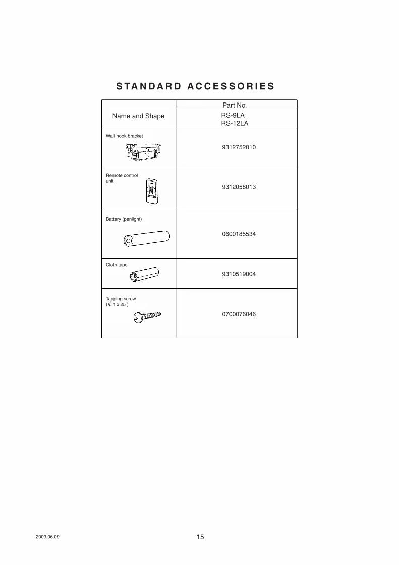
Name and Shape
Part No.
RS-9LA
RS-12LA
Wall hook bracket
Remote control
unit
Battery (penlight)
Cloth tape
9312752010
9312058013
0600185534
9310519004
0700076046
Tapping screw
( 4 x 25 )
S TA N D A R D A C C E S S O R I E S