WA Electrical Requirements - Department of Commerce · this updated version of the WA Electrical...
56
Issued by the Director of Energy Safety WA Electrical Requirements January 2014 Re-issued December 2015 incorporating Amendments No. 1 and No. 2
Transcript of WA Electrical Requirements - Department of Commerce · this updated version of the WA Electrical...
Issued by the Director of Energy Safety
WA Electrical Requirements
January 2014Re-issued December 2015
incorporating Amendments No. 1 and No. 2


WAER January 2014 incorporating Amendments No. 1 October 2015 & No. 2 December 2015 1
Energy Safety Division (EnergySafety) of the Department of Mines, Industry Regulation and Safety, following consultation with network operators and electrical contracting industry groups in Western Australia, issued this updated version of the WA Electrical Requirements (WAER) which applies from 1 July 2014.
Electrical installation designs commenced after 1 July 2014 must comply with this January 2014 version. Designs started before 1 July 2014, and projects under construction or for which building contracts are signed at that date, may comply with the earlier July 2008 version. The application of amendments to the WAER is not retrospective.
Compliance with the WAER is mandatory under Regulation 49 of the Western Australian Electricity (Licensing) Regulations 1991. The WAER should be read with the Electricity Regulations 1947, Part VIII, and the Electricity (Licensing) Regulations 1991. Both sets of regulations take precedence.
The document makes frequent references to relevant Australian Standards. As a general rule, nothing in those standards is replicated in the WAER. The reader needs to refer to the quoted Australian Standards.
Failure to comply with a requirement may result in prosecution under the Electricity (Licensing) Regulations 1991. It may also cause electricity connection delays.
This latest version has been appropriately re-focussed on technical safety compliance requirements and includes the following material changes:
• removal of much of the detailed information on network connection arrangements, which is now covered by network operators’ connection and technical requirements; and
• removal of matters which are now contained in other new or revised statutory instruments or technical standards (such as the Wiring Rules).
As a consequence, the 2008 version has been significantly modified as follows:• numerous changes have been made to definitions in Chapter 2;• much of the content of Chapter 6 has been removed and, in particular, technical requirements for
Service Protection Devices have been modified;• chapter 7 has been extensively modified by removal of much of the detail required in HV Submissions
but important new provisions have been added in relation to ongoing safe operation of high voltage installations;
• the content of Chapter 8 has been deleted with the exception of matters related to Shared Bore Pumps (see new Chapter 9); and
• chapters 9 and 10 have been removed in entirety.
Further amendments may be necessary from time to time and Industry comments will be sought on any material matters prior to publication. The latest version of the WAER is available from EnergySafety’s website (www.energysafety.wa.gov.au).
KEN BOWRONDirector of Energy Safety
Feedback on any aspect of this document is encouraged. Comments and suggestions may be forwarded, at any time, to:
Director of Energy SafetyEnergySafety303 Sevenoaks Street, Cannington, Western Australia 6107fax (08 6251 1901) or email ([email protected]).
Preface

WAER January 2014 incorporating Amendments No. 1 October 2015 & No. 2 December 20152
Table of Contents
Preface ........................................................................................................................................1
1 Introduction .........................................................................................................................4
2 Definitions ...........................................................................................................................5
3 General requirements .........................................................................................................6
3.1 Supply arrangements ..................................................................................................6
3.2 Earthing system ..........................................................................................................8
3.3 On-site power generation ...........................................................................................9
3.4 Point of supply (underground low voltage) ..................................................................9
3.5 Labelling ....................................................................................................................14
3.6 Multiple network points of supply ..............................................................................15
3.7 Privately owned low voltage power lines ..................................................................21
4 Low voltage overhead connections ................................................................................22
4.1 Connection ................................................................................................................22
4.2 Service cable route & point of attachment ................................................................22
4.3 Aerial consumers mains ............................................................................................22
4.4 Spans and clearances ..............................................................................................22
4.5 Consumer poles ........................................................................................................23
4.6 Private poles .............................................................................................................23
5 Low voltage underground connections .........................................................................25
5.1 Connection ................................................................................................................25
5.2 Cables and enclosures .............................................................................................25
5.3 Service connection equipment .................................................................................25
5.4 Protection of consumers mains supplied from substations.......................................26
5.5 Contractor termination of consumers mains .............................................................26
6 Metering and service equipment.....................................................................................27
6.1 General .....................................................................................................................27
6.2 Service Protection Devices .......................................................................................27
6.3 Energisation ..............................................................................................................29
6.4 Earthing of remote metering enclosures ...................................................................29
7 High voltage installations ................................................................................................31
7.1 General requirements ...............................................................................................31
7.2 Design requirements .................................................................................................31
7.3 Commissioning tests and final certification...............................................................32
A2
A1
A2
A1
A1
A1
WAER January 2014 incorporating Amendments No. 1 October 2015 & No. 2 December 2015 3
8 Emergency conditions .....................................................................................................33
8.1 Emergency disconnection .........................................................................................33
8.2 Repair of damaged installations ................................................................................33
8.3 Defective main switch, service protection device or boundary fuse .........................33
8.4 Consumers mains failure ..........................................................................................33
8.5 Mains connection box failure ....................................................................................34
8.6 Warning notices ........................................................................................................34
9 Special requirements for installations in WA ................................................................35
9.1 Application of Wiring Rules Part 1 ............................................................................35
9.2 Consumers mains .....................................................................................................36
9.3 Current-carrying capacity of cables in roof spaces ..................................................37
9.4 Protection of consumers mains .................................................................................37
9.5 Protection of PV Array DC cables .............................................................................40
9.6 Equipotential bonding in shower recesses and bathrooms ......................................40
9.7 Segregation of electrical installations .......................................................................40
9.8 Supply to shared-use domestic bore pumps ............................................................40
9.9 Minimum cross-sectional area of conductors ........................................................... 41
9.10 Jointing consumers mains ........................................................................................ 41
9.11 Reporting of unsafe electrical installations ............................................................... 41
9.12 Applicable standards................................................................................................. 41
9.13 Exemptions ............................................................................................................... 41
10 Network Operators ...........................................................................................................42
10.1 Introduction ...............................................................................................................42
10.2 Western Power – The Southwest Interconnected System ........................................42
10.3 Horizon Power...........................................................................................................43
10.4 Rio Tinto Iron Ore .....................................................................................................44
10.5 BHP Billiton Limited Nickel West Leinster .................................................................46
10.6 BHP Billiton Iron Ore .................................................................................................48
Appendix 1 ................................................................................................................................49
Part 1 Design and Verification Certificate ...........................................................................49
Appendix 2 ................................................................................................................................51
WAER document history .....................................................................................................51A2
A1

WAER January 2014 incorporating Amendments No. 1 October 2015 & No. 2 December 20154
1 Introduction
The WAER applies to all electrical installations, whether connected to distribution networks, transmission networks or stand-alone (‘off-grid’), with operating voltages up to 330kV.
Nothing in this document may be used or interpreted to vary any of the requirements for a consumer installation specified in any of the Australian Standards prescribed in Section 9, unless:
(a) details of such variation(s) are set out in this document; or(b) the relevant Standard has a specific provision for varying the prescribed requirements (for
the matter in question), at the discretion of the network operator.
The WAER sets out minimum requirements for all electrical installations in WA. Network operators may prescribe additional or enhanced requirements as a condition of connection to their networks.
NOTE: Where Amendment No.1 issued in October 2015 amends the original January 2014 edition, an ‘A1’ notation is inserted in the left hand margin. Where Amendment No. 2 issued in December 2015 amends the January 2014 edition, an ‘A2’ notation is inserted in the left hand margin. Full details of each amendment are published separately – see www.energysafety.wa.gov.au.
A1
A2

WAER January 2014 incorporating Amendments No. 1 October 2015 & No. 2 December 2015 5
2 Definitions
The Act: The Electricity Act 1945.
Connection requirements: The requirements of the respective network operator for connection of an installation to its network including:
• technical requirements;• connection arrangements; and• the WADCM (applicable to Horizon Power and Western Power).
Consumer: A legal entity to which electricity is supplied for the purposes of consumption.
Consumer installation: An assembly of electrical wiring, components and equipment downstream from the point of supply, excluding the network operator’s metering equipment, and includes all types of assemblies, such as those in domestic residences and commercial, industrial and institutional premises where persons use electricity in appliances and electrical equipment.
Consumer pole: A private pole required to provide ground clearance for the network operator’s overhead service cables (refer Figure 3.2).
Consumers mains: Has the meaning given in the Wiring Rules.
Contiguous: In contact with or immediately adjacent.
Cyclonic area: As defined in AS/NZS 1170.2 Structural design actions Part 2: Wind actions.
Director: The Director of Energy Safety, as defined in the Energy Coordination Act 1994.
Distribution works: Has the meaning given in the Electricity Act 1945.
Freehold title lot: (Formerly known as green title) A defined portion of land depicted on a plan or diagram for which a separate Crown Grant or Certificate of Title has been or can be issued as defined by the Planning and Development Act.
High voltage: Has the meaning given in the Wiring Rules.
Load: The total maximum electrical power demanded by a consumer’s installation, measured in amperes or watts. This is the maximum demand defined and calculated according to the Wiring Rules.
Network operator: Has the meaning given in the Electricity Act 1945.
Point of attachment: The point at which an aerial service cable is physically secured on a consumer’s structure.
Point of supply: The junction of the consumers mains with – • conductors of the network operator’s distribution works (including the service cable) or
transmission works; or• output terminals of electricity generation works within the premises.
Private pole: A pole supplied and installed by the property owner as required in Section 4.6.
Professionallyqualifiedengineer: Has the meaning given in Part 3 of the Electricity (Licensing) Regulations 1991.
Property boundary: A surveyed line or border of a freehold (green), strata or purple title lot.
Strata title: Lots and common property forming part of a survey strata plan under the Strata Title Act 1985.
WADCM: The Western Australian Distribution Connections Manual published by Horizon Power and Western Power.
Wiring Rules: AS/NZS 3000:2007 as published by Standards Australia.
A1
A1

WAER January 2014 incorporating Amendments No. 1 October 2015 & No. 2 December 20156
3 General requirements
3.1 Supply arrangementsSupply arrangements for consumers shall comply with this document and other statutory requirements. Network operators may have additional requirements for network connection.
For illustrative purposes1, typical connection arrangements for small consumers connecting to low voltage networks are shown in the following figures:
Road reserve
Property boundary
Network
Main switchboard
Network cable (provided by network operator)
Point of attachment / Point of supply
Riser bracket
Consumers mains
Figure 3.1 Overhead service
Road reserve
Property boundary
Network
Main switchboard
Network cable (provided by network operator)
Point of attachment / Point of supply
Riser bracket
Consumers mains
Private pole (provided by property owner)
Figure 3.2 Overhead service with private pole
1 Unless specifically defined in Section 2 of this document, terms used in these figures have the usual common meaning.
A1

WAER January 2014 incorporating Amendments No. 1 October 2015 & No. 2 December 2015 7
Road reserve
Property boundary
Network
Main switchboard
Network cable (provided by network operator)
Point of attachment / Point of supply
Consumers mains
Consumer’s distribution switchboard
Consumer sub-mains
Private pole (provided by property owner)
Figure 3.3 Overhead supply to private pole/main switchboard
Road reserve
Property boundary
Network
Network cable (provided by
network operator)
Point of attachment / Point of supply
Consumer’s distribution switchboard
Consumer sub-mains
Private poles (provided by property owner)
Main switchboard
Riser bracket
Consumer sub-mains
Consumers mains
Figure 3.4 Overhead supply to rural consumer2
Road reserve
Property boundary
Network
Main switchboard
Consumers mains
Network cable (provided by network operator)
Service pillar Point of
supply
Figure 3.5 Overhead street mains and underground consumers mains
2 Underground consumer sub-mains are recommended.
A1
A1

WAER January 2014 incorporating Amendments No. 1 October 2015 & No. 2 December 20158
Road reserve
Property boundary
Main switchboard
Consumers mains
Service pillar Point of
supply
Network
Network cable(provided by network operator)
Figure 3.6 Underground network and underground consumers mains
Road reserve
Property boundary
Consumers mains
Service pillar
Point of supply
Network
Network cable(provided by network operator)
Main switchboard
Distribution board 2
Distribution board 1
Consumer sub-mains
Figure 3.7 Typical underground service to multi-lot built strata
In addition, network operators should be consulted regarding their connection requirements.
3.2 Earthing systemEarthing systems shall comply with the relevant technical standards, including:
• the Wiring Rules;• AS/NZS 2067:2008, Substations and high voltage installations exceeding 1kV a.c.; and• the WAMines Safety and Inspection Regulations 1995.
The earthing system in all electrical installations shall be the Multiple Earthed Neutral (MEN) system as defined by the Wiring Rules, unless otherwise permitted for mining operations.
Further specific requirements may be found in:• the network operator’s connection requirements; and• Energy Networks Association EG(1) Substation Earthing Guide.

WAER January 2014 incorporating Amendments No. 1 October 2015 & No. 2 December 2015 9
3.3 On-site power generationWhere sources of electricity generation are installed in a consumer’s premises, the generator electrical installation shall comply with relevant technical standards including:
• AS/NZS: 3010:2005, Electrical installations – generating sets;• AS 4509.1:2009, Stand-alone power systems – safety and installation;• AS 4777:2005, Grid connection of energy systems via inverters;• AS/NZS 5033:2005, Installation of photo-voltaic (PV) arrays; and• the Wiring Rules.
Further requirements of network operators may be found in their connection requirements.
In particular, where an installation has multiple alternative sources of supply (incorporating either automatic and or manual switching), all associated circuits and equipment including isolating switches shall have signage and labelling as required by the relevant standards. Further detailed labelling requirements are provided in section 3.5 (below).
Installation or modification of on-site power generation is ‘notifiable work’ as defined in the Electricity Licensing Regulations 1991 and, in particular, notices of work shall be submitted to the network operator as required by Regulations 51 and 52.
3.4 Point of supply (underground low voltage)3.4.1 Standard domestic connectionTypical point of supply arrangements for domestic connections are illustrated in the Figures below.
In particular, the following principles apply:1) A network operator’s service pillar on a lot is the point of supply for that lot and (in most
cases) for the adjacent lot (see Figures 3.8(a) & (b)).2) Where a service pillar is installed on a lot, the premise on that lot must be connected to that
pillar (see Figure 3.8(b)).3) If there is no service pillar provided or intended to be provided on the lot of a standard
domestic connection then the consumer mains of the domestic connection can be connected to a pillar on an adjacent lot provided that the pillar:– is correctly positioned as per section 5.3; and– has designated available terminals for that connection.
4) A network operator’s transformer or LV kiosk located on a lot or adjacent road reserve or public open space is not a point of supply for a lot unless the consumers mains for the lot are connected to it (see Figures 3.8(c) & 3.8(d)).

WAER January 2014 incorporating Amendments No. 1 October 2015 & No. 2 December 201510
Road Reserve
Lot A Lot B
Lot D
Lot C
Property boundary Property boundary
Property boundary
Servicepillar
Servicepillar
Survey strata property boundary
The point of supply for Lots A & B is the service pillar on Lot A.(Even if no consumers mains are installed or connected).
The point of supply for Lots C & D is the service pillar on Lot D (even if no consumers mains are installed or connected).
Figure 3.8(a) Example of points of supply
Lot A Lot B
Connection of the installation on Lot A to the pillar on Lot B is not permitted as two points of supply are then created for Lot A.
Service pillar
Consumers mains
Road reserve Property
boundary
Not permitted.Must use the pillar on Lot A.
Service pillar
Figure 3.8(b) Example of points of supply

WAER January 2014 incorporating Amendments No. 1 October 2015 & No. 2 December 2015 11
Road reserve Service
pillar Property boundary
Lot B Lot A
Consumers mains
Network operator transformer or LV kiosk (on lot or in road reserve)
Connection of a house on Lot A is to the pillar on Lot B as the transformer / LV kiosk is not a point of supply.
Figure 3.8(c) Example of points of supply
Road reserve Service
pillar
Property boundary
Lot B Lot A
Consumers mains
Network operator transformer or LV kiosk (on lot or in road reserve)
Connection of a house on Lot A is to the pillar on Lot A as the transformer / LV kiosk is not a point of supply.
Figure 3.8(d) Example of points of supply

WAER January 2014 incorporating Amendments No. 1 October 2015 & No. 2 December 201512
Road reserve Existing service pillar
Easement required if consumer mains not existing at time of subdivision
Survey strata property boundary
Consumer mains
Existing house with UG supply
Property boundary
Road reserve New servicepillar
Survey strata property boundary
Existing house with OH supply
Consumer mains
Overhead service to be removed
Property boundary
Figures 3.8(e) & (f) Examples of ‘battle-axe’ subdivision with and without easements3
Road reserve Existing service
pillar
Free hold property boundary
Consumer mains
Existing house with UG supply
Property boundary
Built strata lot
Consumer mains.
New service pillar
Figure 3.8(g)
3 Details of how to create an easement are available from Landgate.
WAER January 2014 incorporating Amendments No. 1 October 2015 & No. 2 December 2015 13
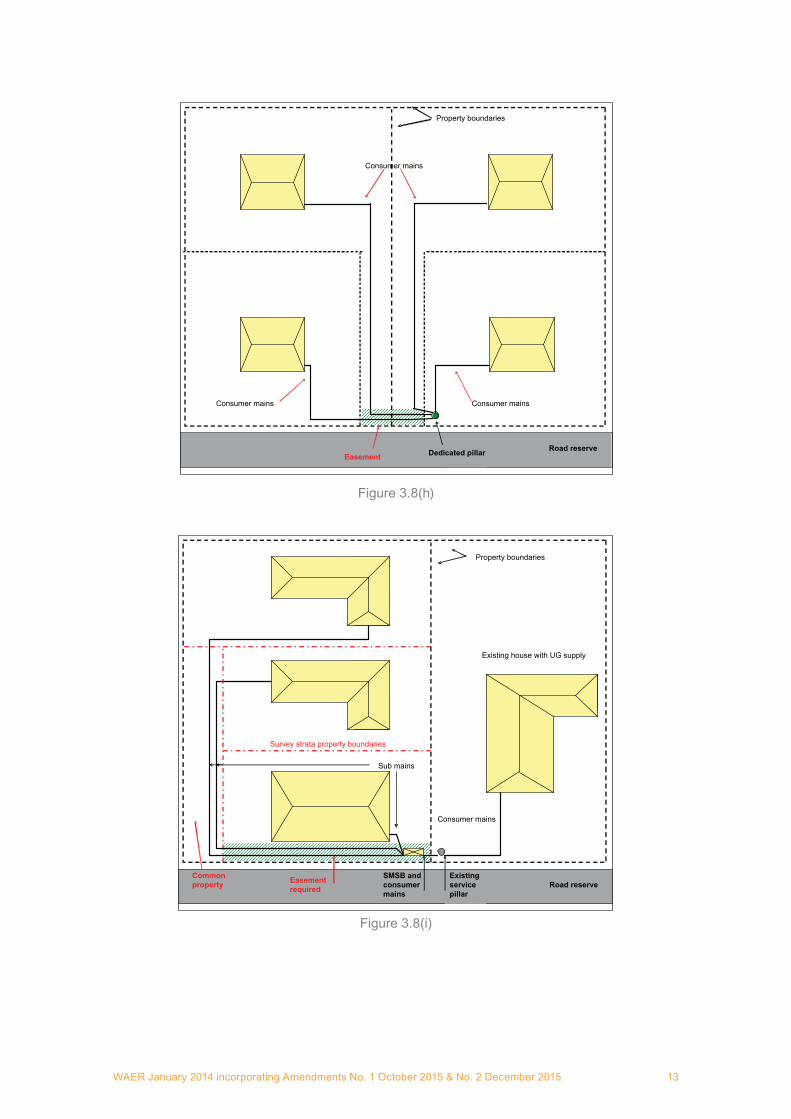
Road reserveDedicated pillar
Property boundaries
Easement
Consumer mains
Consumer mainsConsumer mains
Figure 3.8(h)
Road reserve Existing service pillar
Survey strata property boundaries
Sub mains
Property boundaries
SMSB and consumer mains
Easement required
Common property
Consumer mains
Existing house with UG supply
Figure 3.8(i)

WAER January 2014 incorporating Amendments No. 1 October 2015 & No. 2 December 201514
Road reserve
Point of supply
Main Switchboard
Consumer’s mains
Sub mainsProperty boundary
Built strata development
Figure 3.8(j)
3.4.2 Commercial connectionEach lot shall have its own point of supply. This shall be a service pillar, transformer or LV kiosk located on the lot, or a transformer or LV kiosk located in the immediately adjacent road reserve or public open space, as determined by the network operator.
3.4.3 Non-standard connection.The network operator will determine whether the connection is to be to a service pillar, transformer, LV kiosk or other means.
3.5 Labelling3.5.1 GeneralLabels shall be made of material, able to withstand ultra violet radiation, extreme weather, and vandalism. They shall be indelible, durable, legible and suitably secured for the expected life of the installation.
Technical guidance should be taken from AS 1319:1994, Safety signs for the occupational environment.
Network operators should also be consulted regarding relevant details in their connection requirements.
3.5.2 Consumers mainsThe installer shall label all underground consumers mains at the point of supply. This shall be in addition to any Wiring Rules requirement for marking and recording of underground cable locations. Labels shall be fixed to the outer sheath of the cable in a position that is visible without undue manipulation of the termination or the need for excavation.
The minimum information on labels shall be:• lot or street number (eg lot 70);• unit number/alpha description (eg unit 4B); and• street name.

WAER January 2014 incorporating Amendments No. 1 October 2015 & No. 2 December 2015 15
3.5.3 SwitchboardsElectrical contractors, before requesting or carrying out energisation of an installation, shall ensure that all switchboards are appropriately and uniquely labelled to clearly identify the board’s specific point of supply.
3.5.4 Transformers and LV KioskThe network operator may include a label inside the transformer enclosure warning that a lot has another point of supply where:
• a network operator’s transformer or LV Kiosk is situated on a lot or immediately adjacent in the road reserve;
• it is the network operator’s normal practice to connect a consumer directly to its transformer or distribution frame; and
• the lot is supplied by other means.
Where a service pillar is located on a lot and the supply to the consumer’s installation on that lot originates from a transformer or kiosk, labelling within the service pillar shall identify the origin of the consumer’s supply.
3.5.5 Multiple sources of supplyWhere an installation includes multiple sources of supply, the electrical contractor shall place appropriate warning labels and signage at the generation source(s), network point(s) of supply and at the main switchboard, informing operational and emergency services staff of:
• the existence and location of each source of supply;• type(s) of supply;• point(s) of isolation; and• safe shutdown and isolation procedures.
3.5.6 External equipmentAny permanently installed external free standing electrical equipment that does not form part of a single domestic installation shall be fitted with a label(s) identifying the switchboard from which it receives supply using the unique identifier of that switchboard.
Example: Supply Origin DB1 Circuit R3
3.6 Multiple network points of supply3.6.1 GeneralA network operator shall provide only one point of supply to an individual freehold lot, Crown land title or survey strata lot unless circumstances justify more than one point of supply and safety concerns are satisfied.
The following sections apply where the network operator has approved a consumer’s application for more than one point of supply based on safety, practical and cost considerations.
A1

WAER January 2014 incorporating Amendments No. 1 October 2015 & No. 2 December 201516
3.6.2 Standard minimum requirementsA consumer may identify zones on a lot to which they require separate electricity supplies. In such cases the network operator may approve more than one point of supply to the lot if, in addition to any specific conditions required by the network operator, the installation complies with the following:
• No low or high voltage wiring crosses zone boundaries4.• Zone boundaries, wherever possible, follow easily recognisable site features such as
buildings, fences or driveways and do not unnecessarily deviate from these, intermingle or crossover.
• An up-to-date zone diagram clearly identifying, both electrically and geographically, the extent of every zone and every zone main switchboard location, has been placed in every zone main switchboard and distribution board on the site.
• Every zone main switchboard has a unique identifier.• The locations of the network operator’s points of supply and service equipment in each
zone are clearly identified on the diagram.• Current copies of all zone diagrams have been provided to the network operator in an
acceptable format.• The labelling and signage requirements of section 3.5 and the Wiring Rules have been
complied with, in addition to any particular identification requirements of network operators.• In addition to the requirements of section 3.5, all items within 100m of the dividing zone
boundaries not part of a building (for example free standing lighting, pumps or boom gates) have been clearly labelled with the unique identifier of the zone main switchboard supplying them.
• There is a suitable location for the network operator’s service pillar(s)/equipment.• A Notification under Section 70A of the Western Australian Transfer of Land Act 1893 has
been placed on the property title of every and each:i. freehold lotii. survey strata lotiii. built strata lotiv. Certificate of Crown land titles
warning that the property has more than one point of electrical supply. In addition a copy of the zone diagram and all revisions has been lodged with each Notice.
3.6.3 Commercial and industrial premisesA network operator may provide more than one point of supply for commercial and industrial premises where:
• the requirements listed in section 3.6.2 and this section 3.6.3, whichever is the more stringent, are met;
• each zone has a building with a minimum 4 metre-wide ground level street frontage and contains a building with a main switchboard;
• a current copy of all zone diagrams has been provided to DFES and the relevant local government authority in a format acceptable to them; and
• buildings adjacent to each other but located in separate zones have sufficient separation to be deemed as separate buildings under the Building Code of Australia (BCA).
4 Extra low voltage (ELV) wiring may cross zone boundaries provided its supply source is identified.

WAER January 2014 incorporating Amendments No. 1 October 2015 & No. 2 December 2015 17
A separate zone may be provided for electrical equipment that is remote (electrically or geographically) from buildings or the main switchboard (such as pumps, lighting, boom-gates, communication towers, etc) provided:
• zone boundaries are a minimum of 10 metres from all associated remote equipment and the point of supply; and
• the remote equipment and associated switchboard are at least 50 metres from any building in an adjacent zone.
Zone 1 Zone 2
Zone 3
Zone boundary
Property boundary
Point of supply
Point of supply
Consumers mains
Consumers mains
Min 4m Min 4m
Min 10m
Min 10m Switchboard & pumpMin
50m
Road reserve
Zone boundary
Figure 3.6.3 Commercial and Industrial Premises – example of zone diagram
3.6.4 Built strata lots – domesticA network operator may provide more than one supply point to a group of built strata lots if the requirements listed in section 3.6.2 and the following, are met:
• The zones shall align with the land allocation.• Each zone has a minimum 3 metre-wide ground-level street frontage and contains a
building with a main switchboard.
3.6.5 Survey strata lots – domesticFor a survey strata development zoned domestic and comprising up to three5 survey strata lots, a network operator may provide more than one point of supply provided the installation complies with section 3.6.2 and the following:
• Each zone has a minimum 3 metre-wide ground-level street frontage and contains a building with a main switchboard.
5 For 4 or more lots, the network operator should be consulted.
A1

WAER January 2014 incorporating Amendments No. 1 October 2015 & No. 2 December 201518
3.6.6 Schools, institutions and reservesA network operator may provide more than one point of supply for schools, other institutions and reserves where:
• the requirements listed in section 3.6.2 and this section 3.6.6, whichever is the more stringent, are met;
• each zone has a minimum 4 metre-wide ground level street frontage where there is a building or a minimum 10 metre-wide frontage where there is no building;
• a current copy of all zone diagrams are provided to DFES and the relevant local government authority in a format acceptable to them; and
• buildings adjacent to each other but located in separate zones have sufficient separation to be deemed as such under the Building Code of Australia (BCA).
A separate zone may be provided for electrical equipment that is remote (electrically or geographically) from buildings or the main switchboard (such as reserve/oval lighting, pumps or other equipment) where:
• zone boundaries are a minimum of 10 metres from the point of supply; and• the remote equipment and associated switchboards are a minimum of 25 metres from any
building in an adjacent zone.
Where a reserve/oval is part of the site and may be used for any sporting event, fete, fair or similar gathering, requiring a temporary electricity supply, then either:
• a temporary supply to the lot can be provided in accordance with section 3.6.10; or• a permanent switchboard may be established in a discrete zone with a separate permanent
point of supply for provision of temporary power supplies (which shall comply in all other respects with section 3.6.10) to such events on the site.
Zone 1 Zone 2
Zone 3
Zone boundary
Property boundary
Point of supply
Consumers mains Consumers
mains
Min 4m Min 10m
Switchboard for temporary
supplies
Road reserve
Zone boundary
School
Community Centre
Oval
Lights
Consumers mainsPoint of supply Point of supply
Min 25m
Min 25m
Min 10m
Figure 3.6.6 Schools, Institutions and Reserves

WAER January 2014 incorporating Amendments No. 1 October 2015 & No. 2 December 2015 19
3.6.7 Rural and semi-rural lotsA network operator may provide more than one point of supply if their separation is more than 200 metres and the electrical wiring of each installation maintains a 50 metre separation at all times.
Where these separation requirements cannot be achieved, the minimum requirements are as set out in section 3.6.2.
3.6.8 Rural subdivisions comprising multiple survey strata lots and common propertyFor large rural subdivisions involving multiple survey strata lots and common property, a network operator may provide more than one point of supply if:
• the points of supply are more than 200 metres apart;• all equipment downstream from the network operator’s point of supply is owned by the
strata company;• the site main switchboard(s) is established in accordance with the network operator’s
connection requirements;• a site of adequate dimension is provided by the strata company/site owner for the network
operator’s equipment;• service pillars owned and installed by the strata company/site owner are readily identifiable
as not being the property of the network operator; and• the network operator’s access requirements are met.
3.6.9 Temporary builder’s suppliesThe following are the minimum requirements for provision of a temporary builder’s supply to a lot with an existing point of supply:
• Temporary building supplies shall comply with the Wiring Rules. AS/NZS 3012:2010, Electrical installations – Construction and demolition sites may also contain relevant additional requirements.
• The builder shall be responsible for both the permanent and the temporary supplies while the building site is under the builder’s care.
• The temporary builder’s supply shall service only the building project site and all wires and cables energised from this supply shall be contained within the builder’s operational area, fenced or not.
• Where building work takes place on an adjacent block, the network operator may provide separate temporary builder’s supplies.
The network operator connection requirements may also contain relevant additional requirements.
WAER January 2014 incorporating Amendments No. 1 October 2015 & No. 2 December 201520
3.6.10 Temporary supplies for short term eventsThe following are the minimum requirements for provision of a temporary supply to a lot with an existing point of supply:
• Temporary supplies for short term events shall comply with the Wiring Rules and AS/NZS 3002:2008.
• The event organiser or their representative shall be responsible for both the temporary and permanent supplies during all phases of the short-term event but in so doing the organiser shall not adversely interfere with or interrupt the permanent supply to the site.
• The temporary supply shall service only the event and shall be contained within the event’s operational area, fenced or not.
• No wires or cables energised from the temporary event supply shall cross into adjacent land or beyond the confines of the event concerned.
• On completion of the event the temporary supply shall be entirely removed and the site made electrically safe.
The network operator’s connection requirements may also contain relevant additional requirements.
3.6.11 Existing multiple supply pointsSome developed properties have existing multiple points of supply, installed prior to the existence of the WAER. Some typical examples would be heritage buildings, older terrace housing and small commercial building clusters.
When new developments or renovations are proposed for such properties, a network operator may require the supply arrangements to be modified so that they comply with WAER requirements.
Where a new development or renovation involves only a discrete part of such properties, so that clear separation from the remaining undisturbed portion may be achieved, its modified or upgraded supply shall comply with the relevant part of this Section 3.6.
The existing point or points of supply to the undisturbed section may remain in service provided that:
• the undisturbed electrical installation is safe;• no electrical work is proposed in the undisturbed section to either the supply arrangement
or switchboards;• updated zone diagrams and labelling are placed in every main switchboard in service at
the property;• copies of the zone diagrams are provided to DFES and the relevant local authority in an
acceptable format; and• each point of supply bears sufficient indelible labelling to identify clearly the location and
means of isolation of supply to the whole or part of the undisturbed section to enable rapid and precise disconnection of supply in the event of fire.

WAER January 2014 incorporating Amendments No. 1 October 2015 & No. 2 December 2015 21
3.6.12 Electrical Safety Management PlanWhere more than one point of supply is implemented, supply arrangements are otherwise complex or a requirement of the Occupational Safety and Health Regulations 1996 must be addressed, the consumer may be required to prepare and observe a site-specific Occupational Safety and Health Management Plan. It is the responsibility of the consumer or his representative to ensure that all electrical work performed at the site complies with the Plan, which must meet Occupational Safety and Health Regulation requirements in addition to those set out herein.
These requirements may affect consumers, staff, electrical and other contractors, the network operator and DFES, and may stipulate notifications and procedures required by other local, state or federal regulatory bodies. A copy of the Plan shall be made available on request to an authorised representative of WorkSafe, the network operator or EnergySafety.
3.6.13 Energisation of multiple points of supplyPrior to requesting energisation or permanently energising the installation for a particular zone, the electrical contractor must satisfy the network operator that all stated requirements of this Section 3.6 have been complied with and that all applicable information has been supplied to the relevant entities.
3.7 Privately owned low voltage power linesAll new and replacement low voltage power lines within a consumer installation6 should be installed underground to maximise the safety of the premises and its occupants.
However, in those situations where it is not practical or cost-effective to use an underground system, an overhead (aerial) system may be used, provided that it:
• uses galvanised steel poles or treated timber poles as detailed in Section 4.6;• utilises insulated conductors; and• complies with the requirements of Section 3.12 of the Wiring Rules.
EnergySafety’s publication Guidelines for the safe management of private power poles and lines provides guidance7 on good industry practice for the design, construction and maintenance of privately owned low voltage power lines.
6 For the avoidance of doubt, this includes electrical infrastructure in regional communities where the infrastructure is owned and operated by the community (i.e. electrical assets that are not owned/operated by a network operator).
7 For guidance only; requirements are recommended but are not mandatory.
A1

WAER January 2014 incorporating Amendments No. 1 October 2015 & No. 2 December 201522
4 Low voltage overhead connections
4.1 ConnectionThe network operator shall determine the method of connection in areas serviced by an overhead distribution network.
4.2 Service cable route & point of attachmentThe following factors should be taken into consideration in determining the route of the network operator’s service cable and the position of the point of attachment:
• The location of the network operator’s poles in the street used for supplying the new connection and adjacent properties.
• Geographic features, structures, large vegetation and water features.• The need for, and location of, a consumers pole to maintain correct aerial span lengths and
clearances.• The location of other utility services.• Service protection requirements, especially for rural connections.• The position of the point of attachment shall ensure:
– the route of the service cable is clear of swimming pools, water features, vegetation and building features such as windows, balconies and entrances;
– the area directly below is clear, and can be kept clear, of obstructions;– a minimum clearance of 2.5 metres is maintained between the finished ground or floor
level and the mains connection box or the service cable (up to the point of attachment); and
– where a point of attachment is on a pole, a minimum clearance of 3 metres and a maximum height of 7 metres above ground level is maintained.
4.3 Aerial consumers mainsAerial consumers mains are not permitted.
4.4 Spans and clearancesThe network operator shall determine the maximum span for an overhead service cable.
Overhead service cables shall not cross over or enter the zones of a pool or water feature as defined in the Wiring Rules.
A1
A1

WAER January 2014 incorporating Amendments No. 1 October 2015 & No. 2 December 2015 23
Example AS/NZS 3000
Pool zones
Zone 0
Distribution networkStreet
Property boundary
Common boundary
Consumer’s pole
3500mm min
Network cable
Zone 1
Zone 2
Figure 4.4 Overhead service – pools or spas
Where compliance with this requirement cannot be achieved, the property owner shall either:• replace the overhead service cable with underground consumers mains connected to a
network operator’s service pillar; or• install an intermediate consumer’s pole (section 4.5) on the property located to divert the
service cable away from the pool or water feature zones.
4.5 Consumer poles8
Property owners may be required to supply and install a pole on their property to ensure that:• aerial ground clearances above both trafficable areas and property comply with the Wiring
Rules;• aerial spans do not exceed acceptable limits; and• aerial spans do not pass too close to pools, spas and other buildings.
The design and installation of consumer poles shall comply with the technical requirements of the respective network operator.
A network operator may elect to supply and install the consumer poles on behalf of the property owner in certain cases, but the property owner remains responsible for the continuing maintenance of such poles after installation.
4.6 Private poles9
Property owners may be required to supply, install and maintain pole(s) on their property for the purposes of:
(a) supporting the network operator’s low voltage network cable to provide adequate ground clearance (see definition of ‘consumer pole’ in Section 2); or
(b) providing a point of attachment for the network operator’s low voltage network cable; or(c) supporting privately-owned low voltage power lines.
8 See definition of consumer pole in Section 2.
9 See definition of private pole in Section 2.
A1
A1

WAER January 2014 incorporating Amendments No. 1 October 2015 & No. 2 December 201524
Private poles shall comply with the following relevant technical requirements:1) for the purpose of 4.6(a) – the network operator’s technical requirements;2) for the purpose of 4.6(b) – Section 4 of this document, Section 3.12.6 of the Wiring Rules
and any additional technical requirements of the network operator;3) for the purpose of 4.6(c):(i) are either galvanised steel or Copper Chrome Arsenic (CCA) treated timber; and(ii) section 3.12.6 of the Wiring Rules – this section of the Wiring Rules also provides a
reference to AS/NZS 7000: Overhead line design – Detailed procedures for further detailed technical requirements which may apply in different environments e.g. cyclonic winds and other climatic factors;
4) sawn timber poles and untreated round timber poles shall not be used; and5) steel poles shall be installed in a concrete footing as shown in the following diagram:
100mm minimum (per Wiring Rules)
50mm minimum concrete cover
(per Wiring Rules)
Galvanised steel pole
Concrete
Ground line
Concrete shaped to shed water (per Wiring Rules)
Depth per pole length &
Wiring Rules
Figure 4.6 Steel pole footing details
EnergySafety’s publication Guidelines for the safe management of private power poles and lines provides guidance10 on good industry practice for the design, construction and maintenance of privately owned power poles. In particular, different pole options are recommended in different geographical areas according to predominant soil characteristics and being prone to bushfire.
10 For guidance only; requirements are recommended but are not mandatory.
WAER January 2014 incorporating Amendments No. 1 October 2015 & No. 2 December 2015 25
5 Low voltage underground connections
5.1 ConnectionThe network operator shall determine the method of connection in areas serviced by an underground distribution system.
Special arrangements may apply to consumer’s installations supplied at high voltage or from multiple transformers. Reference should be made to the relevant connection requirements for further information.
5.2 Cables and enclosuresFor multiple consumer installations on a site, common property or easements shall be created to allow consumers mains to be connected to the pillar and or sub-mains to be connected to the site main switchboard. Cables shall run parallel to or perpendicular to the property boundary and shall be within 1.0m of those boundaries.
At the network operator’s discretion, a service easement may be created where a survey strata lot is established and common property is required across the front boundary to ensure all lots can access the pillar with their consumer mains (Figures 3.4(e), (h) & (i)). The consumer is responsible for all costs associated with the creation of the easement.
With the exception of building entry arrangements described in section 9.4, consumers mains cables shall be insulated, sheathed and installed in a heavy-duty non-metallic enclosure over their entire length. Conduit elbows or flexible conduit shall be used to facilitate cable exit from service pillars or cubicles.
Consumers mains shall be installed as a Category ‘A’ system, as defined in the Wiring Rules. Where necessary because of rock, a Category ‘C’ system may be used.
A Category ‘B’ system as defined by the Wiring Rules or steel wire armoured cable shall not be used for consumers mains.
Conduits for above ground outdoor use shall be of a heavy-duty UV resistant type.
5.3 Service connection equipmentThe network operator will provide and install a service connection pillar, pit, panel or frame to facilitate connection of the consumers mains.
The network operator shall determine the location of the service connection equipment.
An unimpeded vertical and 500mm horizontal exclusion zone shall be maintained around service connection equipment providing sufficient space to allow network operator staff, emergency personnel and electrical contractors to access easily and work safely while completing or removing service connections, operating links or fuses.
Trees, shrubs, fences and garden features such as fishponds, gazebos and ornamental paths shall not be placed within the exclusion zone of service connection equipment.
The network operator’s connection requirements may also contain relevant additional requirements.
A1
A1
WAER January 2014 incorporating Amendments No. 1 October 2015 & No. 2 December 201526
5.4 Protection of consumers mains supplied from substationsWhere the installation main switchboard is contiguous with the network operator’s substation enclosure11, the consumers mains do not require over-current protection. If not contiguous, the consumers mains must have over-current protection in the substation.
5.5 Contractor termination of consumers mainsA network operator may authorise an electrical contractor to terminate the consumers mains at the point of supply.
Where a multi-point terminal block is provided in network equipment, only one wire of a consumers mains cable shall be terminated in each tunnel of the terminal block. The network operator is to be contacted if there are insufficient vacant tunnels to complete the termination, which must not proceed until a suitable arrangement has been decided by the network operator.
Doubling of active conductors in one tunnel is only permissible for street light circuits.
11 Where separation is 1 metre (approximately) or less, this is considered to be “contiguous”.
WAER January 2014 incorporating Amendments No. 1 October 2015 & No. 2 December 2015 27
6 Metering and service equipment
6.1 GeneralMetering and service equipment shall comply with the relevant network operator’s connection requirements.
Where augmentation of an existing non-standard metering arrangement (such as plug-in meters) is required, the network operator must be consulted prior to any changes being made.
This section provides particular requirements for low voltage installations only. [For high voltage installations, further details should be obtained from the relevant network operator.]
6.2 Service Protection DevicesThe purpose of a Service Protection Device (SPD) is to:
• electrically protect the consumers mains12 and metering equipment from the effects of short circuit faults within an electrical installation;
• provide a point of electrical isolation for:– safe replacement of metering equipment; and– the network operator.
6.2.1 General requirementsAn SPD is required in all consumer installations.
Both an SPD and a main switch must be provided on direct connected metering installations.
For CT connected metering installations, the SPD does not replace the main switch except for sole-use substations, where the transformer circuit breaker need not be duplicated.
As part of determining the supply arrangement, the network operator will provide the protection grading requirements for the purpose of SPD selection.
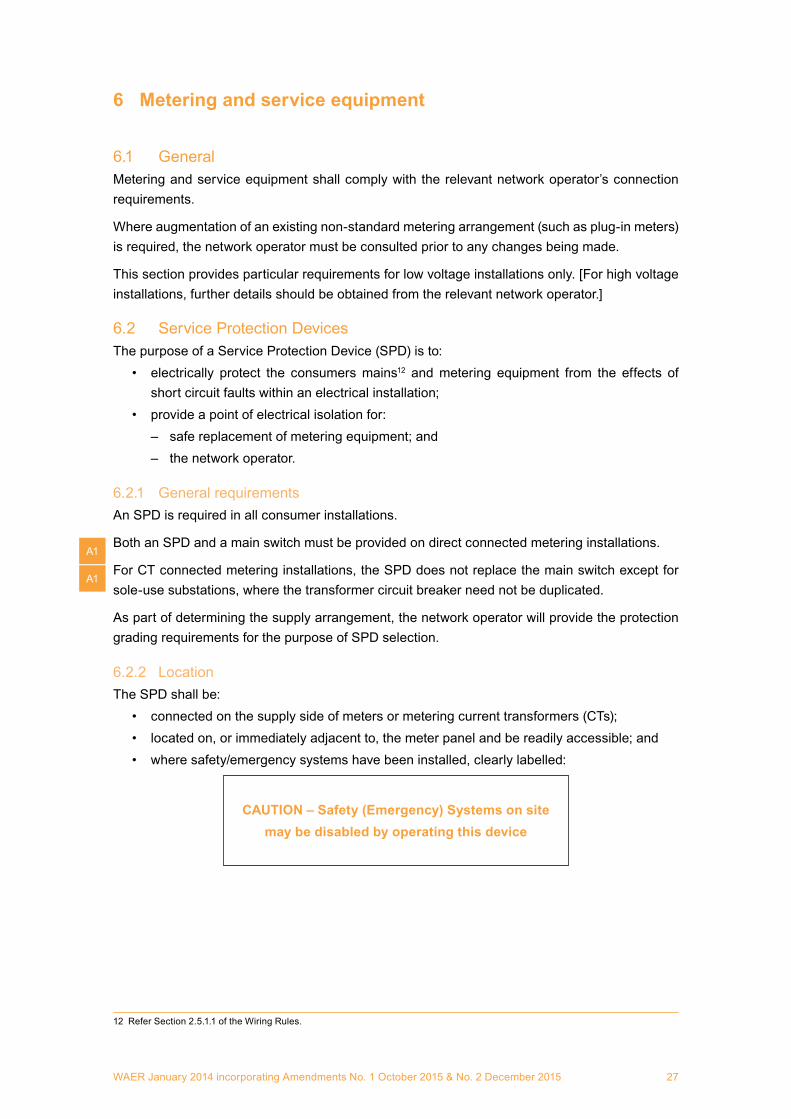
6.2.2 LocationThe SPD shall be:
• connected on the supply side of meters or metering current transformers (CTs);• located on, or immediately adjacent to, the meter panel and be readily accessible; and• where safety/emergency systems have been installed, clearly labelled:
CAUTION – Safety (Emergency) Systems on sitemay be disabled by operating this device
12 Refer Section 2.5.1.1 of the Wiring Rules.
A1
A1

WAER January 2014 incorporating Amendments No. 1 October 2015 & No. 2 December 201528
6.2.3 SPD for direct metering
6.2.3.1 Maximum demand not exceeding 100AThe SPD for permanent installations with direct connected metering and a maximum demand not exceeding 100A shall be a HRC fuse(s), and shall:
• have a continuous rating of 100A (base and holder);• unless otherwise approved by the network operator, have a rated short circuit breaking
capacity of not less than 25kA13;• be suitable to accept a Type IIa current limiting (HRC) fusible link (22 mm barrel)
manufactured to the requirements of AS 60269.3:2005 or its IEC equivalent standard; and• provide robust facilities for:
– a seal to be fitted when the fuse link is in place; and– a seal or a tag to be fitted when the fuse link is removed.
For builders’ supplies, the SPD may be either a HRC fuse or miniature circuit breaker with the following ratings:
• A continuous rating of 100A (base and holder).• A rated short circuit breaking capacity of not less than 25kA.
6.2.3.2 Maximum demand greater than 100AFor installations with direct connected metering and a maximum demand exceeding 100A (such as a multiple master metering or distributed master metering arrangement):
• The SPD shall be a circuit breaker or combined switch-fuse (CFS) unit of a type acceptable to the network operator, and shall:– have a continuous current rating to accommodate the maximum demand;– unless otherwise approved by the network operator, have a rated short circuit breaking
capacity of 25kA minimum8;– be capable of discrimination with both upstream and downstream protective devices;
and– be able to be locked and tagged in the ‘off’ position.
• Each individual meter shall be electrically protected with a fuse meeting the specified requirements of section 6.2.3.1.
6.2.4 SPD for CT meteringThe SPD for installations with CT connected metering shall be a circuit breaker or combined switch-fuse (CFS) unit of a type acceptable to the network operator and shall:
• have a continuous rating appropriate to meet consumer requirements; and• have a minimum rated short circuit breaking capacity of 25kA unless otherwise specified
or approved by the network operator;• be capable of discrimination with both upstream and downstream protective devices; and• be able to be locked and tagged in the ‘off’ position.
13 A lower rating may be approved by the network operator where specifically assessed by a suitably qualified electrician or professionally qualified engineer as being equal to or greater than the prospective fault level at the point of supply or where nominated by the network operator as appropriate.
A1

WAER January 2014 incorporating Amendments No. 1 October 2015 & No. 2 December 2015 29
6.3 EnergisationThe electrical contractor may operate the SPD to check the operation of the meter(s) where direct connected meter(s) are installed.
On completion of this work, either the fusible element(s) shall be removed or the circuit breaker(s) returned to the ‘off’ position and tagged.
The electrical contractor shall inform the network operator of the termination details (section 3.5.7).
An ‘out-of-service’ tag shall be attached to the SPD(s) to indicate that only the network operator’s authorised representative may remove the tag and energise the installation. This will be done after receipt of the Notice of Completion from the electrical contractor.
6.4 Earthing of remote metering enclosuresWhere a remote metering enclosure (separate from the main switchboard) is required for network operator access to metering equipment, the enclosure shall be effectively earthed by either of the two methods described in Section 5.5.3.5 of the Wiring Rules, namely:
Method 1The enclosure is connected to the consumers mains neutral by a conductor of cross sectional area not less than the neutral conductor, as shown in Figure 6.4.1.
N
MEN
N E
Meter
SPD
A N N A
ABond
Main switchboardMeter enclosure
Point of
supply
Figure 6.4.1 Neutral bonding of remote metering enclosure
The main neutral conductor must be continuous (i.e. unbroken) and connection may be made by:• Splicing, soldering and taping; or• Using a two screw connector and then taping.
This does not preclude other methods of jointing provided they comply with the Wiring Rules.
This method must not be used where the metering enclosure and switchboard are mounted on the same metal-framed building structure.
A2
A1

WAER January 2014 incorporating Amendments No. 1 October 2015 & No. 2 December 201530
Method 2The enclosure is connected to the earth bar in the main switchboard via an earthing conductor of the same size as the consumers mains neutral, as shown in Figure 6.4.2.
N
MEN
N
Meter
Meter enclosure
SPD
A N N A
A
Main switchboard
EPoint
of supply
Figure 6.4.2 Connection of remote metering enclosure to main earth
Method 2 must be used where the metering enclosure and switchboard are mounted on the same metal-framed building structure.
WAER January 2014 incorporating Amendments No. 1 October 2015 & No. 2 December 2015 31
7 High voltage installations
7.1 General requirementsConsumer high voltage electrical installations must be designed, constructed, maintained and operated by competent persons, consistent with good industry practice, to ensure the ongoing safety of personnel, equipment, property and the public.
The fundamental requirements specified in Regulations 49, 49A and 49B of the Electricity (Licensing) Regulations 1991 and Chapter 9 of this document must be observed.
The technical requirements for the design of HV installations are contained in various technical standards which include, but are not limited to:
• AS/NZS 2067:2008;• the Wiring Rules;• AS/NZ 7000:2010; and• network operators’ connection requirements.
Network operators may also have additional requirements for specific connection locations.
A consumer’s HV installation commences at the point of supply as designated by the network operator (where connected to a network) and/or at the source of HV supply from on-site generating plant.
HV installations on mine sites are also required to comply with mines safety inspection legislation administered by the Resources Safety Division of the Department of Mines and Petroleum.
7.2 Design requirements7.2.1 Design detailsHV installation design details shall include, but not be limited to, the following information:
• Site plans.• Single line diagrams.• Electrical load calculations.• Control of incoming supplies and metering arrangements.• Earthing system design calculations.• Primary plant details – generators, motors, power transformers, switches, current and
voltage transformers.• Protection scheme.• Applicable technical standards.• Time schedule for initial commissioning supply and permanent connection.• Safe operating procedures.• Equipment maintenance requirements.
The network operator may also request additional information for particular HV installations.
7.2.2 Design certificationFor all proposed new HV installations and subsequent modifications or upgrades, the HV installation design is to be developed and certified in writing by a professionally qualified engineer as complying with all relevant technical requirements.

WAER January 2014 incorporating Amendments No. 1 October 2015 & No. 2 December 201532
7.2.3 Operation and maintenance of HV installationsIt is the responsibility of the HV installation designer to provide the installation owner/operator with:
• a set of HV operating and safe working procedures to manage the ongoing safety of personnel and equipment in accordance with good electricity industry practice14; and
• a maintenance schedule for the HV and other electrical equipment.
The procedures and plan shall be designed to achieve compliance with the requirements of the relevant legislation, Australian Standards and applicable codes of practice.
Further recommended requirements are provided in the EnergySafety publication15 Guidelines for the Safe Management of High Voltage Electrical Installations.
Where the HV installation is to be connected to a network, the designer shall formally notify the network operator when the safe operating procedures and recommended maintenance plan have been provided to the installation owner/operator.
7.2.4 HV submissionsThe requirements for HV design submissions16 (inclusive of safety procedures and maintenance recommendations) are as follows:
• HV submissions should be made prior to commencement of construction.• Where connection to a network is required, the certified installation details must be
submitted to the network operator17 in reasonable time to enable review prior to the network connection proceeding.
• In addition, in the case of mine sites, the submission must be forwarded to the Resources Safety Division of the Department of Mines and Petroleum, in accordance with regulation 5.18 of the Mines Safety and Inspection Regulations 1995.
• In the case of HV installations not connected to a network, a HV submission is not required. [However, the installation must otherwise comply with the relevant requirements of this Chapter 7.]
7.3 Commissioning tests and final certificationFinal commissioning tests are required to prove the satisfactory performance of the installation in meeting the design requirements. These tests shall be performed by a competent service provider acceptable to the network operator (where applicable).
In the case of network connections, satisfactory test results for all electrical equipment between the point of supply and the main switch shall be recorded and submitted to the network operator prior to permanent supply being made available.
Final certification is required by a professionally qualified engineer that the ‘as commissioned’ installation complies with the design and all relevant technical requirements. A copy of the final certification shall be provided to the network operator (where the installation is connected to a network).
14 Or demonstrate, where applicable, that existing site operating protocols meet the requirements.
15 At the time of publication of this revised WAER, these guidelines were being developed but not yet published.
16 Submissions must include all items listed in section 7.2.1.
17 For large and complex installations (eg a new major hospital or mining development), staged submission of installation details may be made where agreed by the network operator.
WAER January 2014 incorporating Amendments No. 1 October 2015 & No. 2 December 2015 33
8 Emergency conditions
8.1 Emergency disconnectionUnder emergency conditions, an electrical contractor may open the SPD or otherwise isolate the installation from the low voltage electricity supply to ensure their own, occupants’ and the public’s safety.
Care shall be exercised not to unnecessarily isolate any emergency equipment such as fire-fighting services or evacuation aids.
The installation must then be made electrically safe before the installation can be re-energised.
8.2 Repair of damaged installationsTemporary repairs may be made to enable occupants to use all or designated parts of the consumer installation for a short period while permanent repairs are arranged.
The network operator must be notified by the electrical contractor of the temporary repairs to an installation as soon as practicable after it is re-energised.
An emergency or temporary repair must only remain in service for a maximum period of 14 calendar days (21 days for isolated country districts).
A Notice of Completion and Electrical Safety Certificate shall be forwarded by the electrical contractor to the network operator and the installation owner respectively on completion of the permanent repairs.
8.3 Defective main switch, service protection device or boundary fuseShould a consumer’s main switch, service protection device or boundary fuse become defective, the network operator or an electrical contractor authorised by the network operator may disconnect, and later reconnect, the electrical supply to enable replacement by the consumer’s electrical contractor.
8.4 Consumers mains failureAn electrical contractor may provide emergency consumers mains to an installation to maintain electricity supply when failure or damage to the permanent consumers mains has occurred.
The installation of a temporary service shall not create any additional electrical hazard(s). In all cases the temporary consumers mains shall be double insulated along their entire route length and positioned so as to ensure protection from further damage.
The following work shall be undertaken:• Where the consumers mains switchboard is damaged, deemed unsafe or is unserviceable
a panel suitable to house an emergency main switch shall be supplied and installed.• The existing main earth electrode and conductor shall be confirmed as operational or
replaced as a part of the temporary repairs.• The MEN connection for the temporary arrangement is to be re-made at the consumer’s
neutral link (not at the network operator’s meter or neutral link).

WAER January 2014 incorporating Amendments No. 1 October 2015 & No. 2 December 201534
As a part of the permanent repairs the electrical contractor shall ensure that:• consumers mains comply with statutory and network operator requirements;• consumer mains are labelled in accordance with section 3.5;• the main switchboard complies with the statutory and network operator requirements;• 75 mm rear clearance is provided for existing meter enclosures, provided that a consumers
mains cable size of 16 mm2 is not exceeded;• main earth, installation earths and MEN comply with statutory requirements; and• the installation is electrically safe and free from hazards.
8.5 Mains connection box failureThe network operator may carry out repairs to the mains connection box when failure or damage has occurred.
8.6 Warning noticesAfter installing an emergency supply or carrying out temporary repairs, the electrical contractor shall leave a warning notice in the main switchboard before leaving the site and immediately notify the network operator.
The warning notice shall describe the emergency/temporary work and provide contact details should it be necessary for anyone to discuss the arrangement with the electrical contractor.
The warning notice should indicate when permanent repairs to the installation are expected to be carried out. The warning notice shall only be removed by the electrical contractor on completion of the permanent repairs and submission of the appropriate notices.

WAER January 2014 incorporating Amendments No. 1 October 2015 & No. 2 December 2015 35
9 Special requirements for installations in WA
Under Regulation 49 of the Electricity (Licensing) Regulations 1991, the requirements set out below, which are additional to or at variance with the Wiring Rules and other Australian Standards, take precedence over those appearing in the Australian Standards and are mandatory.
9.1 Application of Wiring Rules Part 1Electrical installation designers choosing to use a Wiring Rules Part 1 design and installation solution (rather than apply the deemed to comply require ments of Part 2) must comply with section 1.9.4 of the Wiring Rules and the following additional requirements.
Designers must not adopt a Part 1 solution for the following types of electrical installations, which must comply with Part 2 of the Wiring Rules and the applicable standard or standards referred to in Section 9.12:
• domestic installations;• construction and demolition sites;• medical treatment areas;• relocatable installations and the site installations to supply them;• marinas and pleasure craft; and• shows and carnivals.
Design workDesigners must be competent to carry out designs that depart from Part 2 of the Wiring Rules under the provisions of section 1.9.4.1. For the purposes of this requirement, the following persons may be considered competent:
• Currently licensed electricians (previously known as electrical installers) with at least 10 years experience in the design and construction of consumer’s electrical installations (other than domestic installations) since qualifying, including not less than 5 years design experience in total.
• Electrical designers holding a TAFE Advanced Diploma in Electrical Engineering (or equivalent) and have at least 5 years experience in the design of consumer’s electrical installations (other than domestic installations).
• Professionally qualified engineers with at least 5 years experience in the design of consumer’s electrical installations (other than domestic installations).
The designer must establish and retain for at least 10 years a folder that contains:– the document referred to in Clause 1.9.4.2 of the Wiring Rules, which contains the
installation owner’s or operator’s acknowledgment and acceptance that some parts of the installation do not conform to Part 2 of the Wiring Rules; and
– the specific information listed in Clause 1.9.4.3 ‘Documentation’ of the Wiring Rules.
The designer is also required to provide one copy of the folder and contents to the person with overall responsibility for the installation, and a further copy to the person engaged to verify the compliance of the installation.
The designer shall make his/her folder available for examination by an Inspector (Electricity), if requested.
Additionally the designer shall complete Section A of the “Part 1 Design and Verification Certificate”.
A1

WAER January 2014 incorporating Amendments No. 1 October 2015 & No. 2 December 201536
Verification of complianceBoth the design and construction of the parts of the installation that do not comply with Part 2 of the Wiring Rules are required to be independently assessed to confirm compliance with the requirements listed in Wiring Rules Clause 1.9.4.1 paragraphs (a), (b) and (c), as required by Clause 1.9.4.4.
This verification assessment work may only be carried out by persons who:• were not involved in the design of the installation; and• do not report to the designer (ie They may be part of the same organisation, subject to
these constraints);and who are one of the following:
– Currently licensed electricians (previously known as electrical installers) with at least 10 years experience in the design and construction of consumer’s electrical installations (other than domestic installations) since qualifying, including not less than 5 years design experience in total.
– Electrical designers holding a TAFE Advanced Diploma in Electrical Engineering (or equivalent) and have at least 5 years experience in the design of consumer’s electrical installations (other than domestic installations).
– Professionally qualified engineers with at least 5 years experience in the design of consumer’s electrical installations (other than domestic installations).
On completion of the verification assessment, the verifier may, if satisfied, complete Section B of the ‘Part 1 Design and Verification Certificate’ appended to this document.
It is the designer’s responsibility to ensure the verification work is carried out.
When completed by both the designer and verifier, the certificate must be placed on the project folder referred to above, and retained by the designer for at least 10 years. A copy of the certificate shall be provided to the network operator on request.
9.2 Consumers mains9.2.1 DesignSingle and multi-phase consumers mains shall have a minimum current-carrying capacity of 32A per phase, except for:
• single domestic installations, where the minimum current-carrying capacity shall be:– Single-phase: 63A– Multi-phase: 32A per phase
and• multiple installations which incorporate a domestic installation, where the minimum current-
carrying capacity shall be:– Single-phase: 63A– Multi-phase: 63A per phase.
The minimum cable sizes used for consumers mains to domestic premises shall be:• single-phase: 10 square millimetres, copper conductors; or• three-phase: 6 square millimetres, copper conductors.
WAER January 2014 incorporating Amendments No. 1 October 2015 & No. 2 December 2015 37
When calculating voltage drop in an installation, the component of voltage drop across the consumers mains shall be assessed using the maximum demand of the installation or 80% of the minimum current carrying capacity specified above, whichever is the greater.
Installation designers should bear in mind the steadily growing demand maxima imposed by domestic dwellings, especially with the increasing popularity of split-cycle and central air conditioning. To allow for demand growth, and the possibility of all-electric homes, designers and contractors should consider installing 16 and 10 square millimetre copper conductors respectively for single-phase and three-phase consumers mains.
9.3 Current-carrying capacity of cables in roof spacesFor the purpose of calculating current-carrying capacity, wiring systems shall be installed in the roof space of buildings on the assumption that ceiling thermal insulation, if not currently installed, will be installed in the future.
If a length of cable not exceeding 150mm passes through bulk thermal insulation (for example to connect to a lighting point), it shall not be considered as being surrounded by thermal insulation.
Where cables are installed in a manner permitting the free circulation of air around them (for example in a wiring enclosure of adequate dimensions, and in any case, of dimensions not less than 50mm × 100mm), the cables shall not be considered as being surrounded by thermal insulation.
9.4 Protection of consumers mains9.4.1 Consumers mains in wall cavitiesInsulated and sheathed consumers mains are permissible without enclosure in heavy duty conduit when installed in the cavity of double-brick walls (reference Clause 3.9.7.1.2 of Wiring Rules).
9.4.2 Building entryProvision shall be made during construction of the building for the consumers mains conduit to pass through the building foundations and into either the building or the wall cavity.
If such provision has not been allowed, the portion of this conduit rising up to and around the footing to the point of entry into the wall cavity shall be protected against impact damage, movement and water ingress by robust means such as a galvanised steel pipe or equivalent (refer also to section 9.4.1).

WAER January 2014 incorporating Amendments No. 1 October 2015 & No. 2 December 201538
Meter enclosure
Finished ground level
500mm
Figure 9.4(a) Conduit entry through slab – double brick
Meter enclosure
Finished ground level
500mm
Stud wall
Brick wall
Figure 9.4(b) Conduit entry through slab – brick veneer

WAER January 2014 incorporating Amendments No. 1 October 2015 & No. 2 December 2015 39
foundations
Floor slab
Inte
rior w
all
exte
rior w
all
50mm
Conduit protruding into wall cavity
Galvanised pipe extending from conduit elbow or bend to a minimum of 50mm into exterior wall
Consumers mains conduit
Finished ground level
500mm
Meter enclosure
Figure 9.4(c) Conduit entry through wall – double brick
foundations
Floor slab
50mm
Conduit extending to meter enclosure
Galvanised pipe extending from conduit elbow or bend to a minimum of 50 mm into exterior wall
Consumers mains conduit
Finished ground level
500mm
Meter enclosure
Inte
rior w
all –
stud
wall
Brick
wall
Exte
rior w
all
Figure 9.4(d) Conduit entry through wall – brick veneer

WAER January 2014 incorporating Amendments No. 1 October 2015 & No. 2 December 201540
9.4.3 Connection at point of supplyUnderground consumers mains shall be protected mechanically over their entire length as required in Section 5.2.
Where consumers mains are installed on external surfaces of property owners’ structures (eg consumer pole, external walls, under eaves), they shall be installed in a heavy-duty non-metallic enclosure to provide appropriate mechanical and waterproofing protection in accordance with section 3 of the Wiring Rules.
9.5 Protection of PV Array DC cablesInsulated and sheathed d.c. cables may be installed in the cavity of double-brick walls without enclosure in heavy duty conduit (reference Clause 4.3.6.3.2 of AS/NZS 5033:2014) but shall otherwise comply with the requirements of AS/NZS 5033:2014.
9.6 Equipotential bonding in shower recesses and bathroomsEquipotential bonding of the conducting metal reinforcing mesh within concrete floors and walls forming part of a shower recess or bathroom is not required (Clause 5.6.2.5 of the Wiring Rules).
9.7 Segregation of electrical installationsExcept for the following listed circumstances, no part of installation wiring or consumers mains from one lot shall cross into another lot. The exceptions are:
• if electrical zones have been established as required under Section 3.6 of this document, the consumers mains or installation wiring may cross into another lot if they remain within their zone;
• wiring within common property (see section 5.1 and section 9.8);• consumers mains may cross into an adjacent lot in the vicinity of a service pillar or other
similar network operator point of supply, if the consumer mains are to be connected into that pillar; and
• if an enterprise operates over adjacent lots and one service supplies all such lots, installation wiring may extend over the lots.
Where a fire-rated barrier separates individual enterprises the electrical services of either enterprise shall not cross such fire rated barriers.
Consumers mains may only cross or be located in road or other reserves (such as public open space) when:
• the area they enter is the site of a network operator’s substation and the consumers mains are to be connected into the substation; or
• they are associated with a network operator approved installation such as an unmetered supply.
9.8 Supply to shared-use domestic bore pumpsTwo or more domestic consumers may provide separate supplies to a common load such as a bore pump installed on, or straddling, the property boundary as follows:
• Wiring shall be arranged so that only one supply can service the load at any one time and the two supplies cannot be interconnected.
• Appropriately rated socket outlets may be installed on either side of the boundary and supplied from the electrical installations of the respective properties. Alternative means of supply may be submitted to the network operator for approval. A changeover switch arrangement is not acceptable.
A1

WAER January 2014 incorporating Amendments No. 1 October 2015 & No. 2 December 2015 41
• The pump may be connected to either socket outlet using a flexible cord and plug. An isolating switch capable of being locked open shall be located adjacent to the load.
• A durable, easily legible notice shall be fixed on the isolating switch warning that supply may originate from either of two sources. Further details about acceptable technical standards for notices and labels are provided in section 3.5.
Where a bore pump is shared-use but is located within the confines of one property, the supply to it must originate from the electrical installation in that property only.
Extra low voltage control cabling from one property may cross into the associated adjoining property.
9.9 Minimum cross-sectional area of conductorsIn domestic installations, conductors for final sub-circuits supplying socket outlets shall have a cross-sectional area of not less than 2.5mm².
The exception to this is that installation of socket outlets on lighting circuits is acceptable for connection of luminaires and other appliances rated at not more than 150 watts provided the socket outlet location is more than 2.3 metres above the floor and the requirements of Clause 3.5.1 of the Wiring Rules are met.
9.10 Jointing consumers mainsJoints in consumers mains are to be avoided wherever possible. If jointing is unavoidable, electrical contractors should apply to the relevant network operator for approval.
9.11 Reporting of unsafe electrical installationsWhere an electrical worker identifies a defect in an electrical installation that renders that installation unsafe, Regulation 62 of the Electricity (Licensing) Regulations 1991 requires that person to advise the electrical contractor, who shall report the matter to the owner and the relevant network operator (or the Director).
Such defects include, but are not limited to:• unenclosed electrical joints in ceiling spaces; or• degraded wiring insulation.
Where occurrences of unenclosed joints or degraded wiring insulation have already been rectified, no reporting is required under Regulation 62.
The fitting of an RCD, while recommended, is not acceptable (on its own) as an effective remedial action for such defects.
9.12 Applicable standardsReferences are made throughout this document to relevant technical standards that apply to various aspects of electrical installations.
Electrical work must be carried out so as to comply (where applicable) with the latest version of those standards listed in Schedule 2 of the Electricity (Licensing) Regulations 1991.
9.13 ExemptionsUpon written application, the Director may exempt in writing any consumer, network operator or other person from complying with a requirement set out in this document, or to vary the application of any requirements, subject to any conditions the Director stipulates.
As a general rule, the Director will not consider an exemption from the normal requirements set out in this document unless the applicant clearly demonstrates in writing the special circumstances that may justify such an action, including a comprehensive risk assessment.
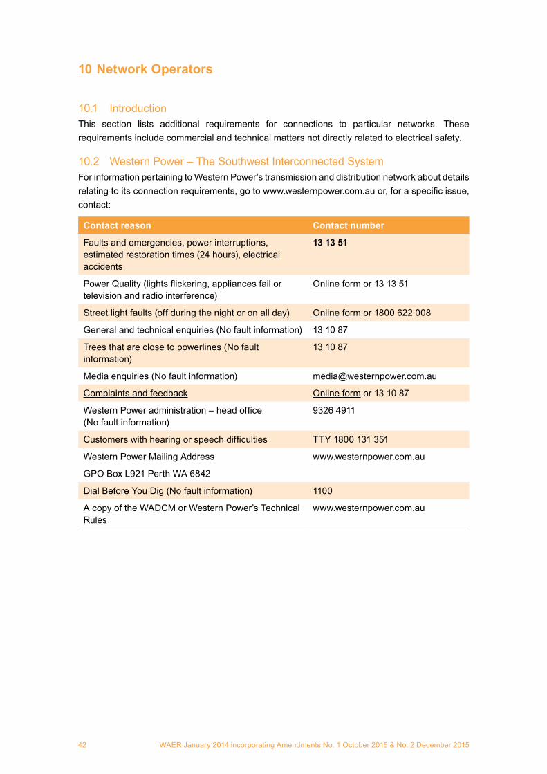
WAER January 2014 incorporating Amendments No. 1 October 2015 & No. 2 December 201542
10 Network Operators
10.1 IntroductionThis section lists additional requirements for connections to particular networks. These requirements include commercial and technical matters not directly related to electrical safety.
10.2 Western Power – The Southwest Interconnected SystemFor information pertaining to Western Power’s transmission and distribution network about details relating to its connection requirements, go to www.westernpower.com.au or, for a specific issue, contact:
Contact reason Contact number
Faults and emergencies, power interruptions, estimated restoration times (24 hours), electrical accidents
13 13 51
Power Quality (lights flickering, appliances fail or television and radio interference)
Online form or 13 13 51
Street light faults (off during the night or on all day) Online form or 1800 622 008
General and technical enquiries (No fault information) 13 10 87
Trees that are close to powerlines (No fault information)
13 10 87
Media enquiries (No fault information) [email protected]
Complaints and feedback Online form or 13 10 87
Western Power administration – head office (No fault information)
9326 4911
Customers with hearing or speech difficulties TTY 1800 131 351
Western Power Mailing Address
GPO Box L921 Perth WA 6842
www.westernpower.com.au
Dial Before You Dig (No fault information) 1100
A copy of the WADCM or Western Power’s Technical Rules
www.westernpower.com.au

WAER January 2014 incorporating Amendments No. 1 October 2015 & No. 2 December 2015 43
10.3 Horizon PowerFor information pertaining to Horizon Power’s transmission and distribution networks about details relating to its connection requirements, go to www.horizonpower.com.au or, for a specific issue, contact:
Faults and emergencies, power interruptions, estimated restoration times (24 hours), electrical accidents
13 23 51
Street light faults 1800 264 914 or online form
Complaints / Enquiries – Residential
– Business
1800 267 926
1800 737 036
Trees and Powerlines (No fault information) Please contact your local Horizon Power Office
Dial Before You Dig (No fault information) 1100
Media enquiries (No fault information) 1800 799 745
Horizon Power – head office (No fault information)
9159 7250
Horizon Power Administration 6310 1000
Horizon Power
PO Box 817, Karratha WA 6714
www.horizonpower.com.au
A copy of the WADCM www.horizonpower.com.au
Non-interconnected townsHorizon Power has a number of remote towns supplied by a local power station. In some locations there are restrictions on the size of an installation’s total load and of individual motors that may be connected to the local power supply. Refer to the WADCM for specific details.
Under frequency load shedding and demand side managementHorizon Power may require the fitting of devices to air conditioners that enable disconnection from the network during power disturbances. Refer to the WADCM for specific details.
Horizon Power also reserves the right to disconnect discrete loads from the network during power system contingencies. Refer to the WADCM for specific details.

WAER January 2014 incorporating Amendments No. 1 October 2015 & No. 2 December 201544
10.4 Rio Tinto Iron Ore10.4.1 IntroductionRio Tinto operates an electricity network, on behalf of the entities authorised under the Iron Ore (Hamersley Range) Agreement Act 1963 and Iron Ore (Robe River) Agreement Act 1964, in the Pilbara.
The following requirements are particular to Rio Tinto’s (network operator) electricity network, including but not limited to the towns of Dampier, Wickham, Tom Price, Paraburdoo and Pannawonica, and their interconnecting transmission system.
10.4.2 DefinitionsAuthorised person: Any person appointed in writing by an authorised employee of the network operator for the purpose of working on network operator equipment.
10.4.3 General requirementsApplication for a new connection or substantial increase in connected load must be made on the standard form(s) obtained from the network operator, so that the capacity of the network to supply the load can be investigated. Refer to section 10.4.7 below for contact information.
Significant expenses should not be incurred as a result of a new connection or substantial load increase prior to receipt of a written approval to any such application.
Connection to Rio Tinto Iron Ore’s distribution system shall only be made by a network’s officer or other authorised person.18
10.4.4 LV Earthing SystemTwo earthing systems are used:
• Direct earthing by laid up network operator’s earth; and/or• MEN system.
The MEN system is to be used for all new or upgraded electrical installations unless advised otherwise by the network operator.
10.4.5 Service and metering equipmentThe network operator will supply revenue meters for installation by a Network Officer or other authorised person. The consumer may be required to pay the cost of purchase of any such meters as determined by the network connection agreement.
Meter test blocks shall be fitted to all CT metered installations.
Commercial tariff meters are to be installed in a separate pad-lockable cubicle complete with viewing window.
Where it is necessary to lock switchboard enclosures containing service and metering equipment, only Yale 490-25 MK PI cam locks or padlocks which incorporate a Rio Tinto Iron Ore master key pattern will be accepted.
10.4.6 Emergency conditionsAccess to the network operator’s equipment such as supply pillars and pole mounted protective devices shall be by Network Officer or other authorised persons only.
18 Deviation to these requirements shall be subject to formal risk assessment by the network operator.
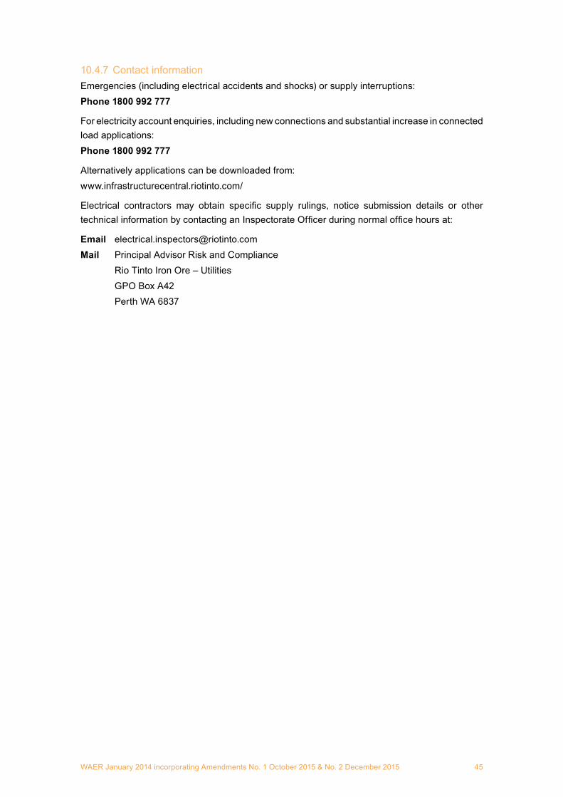
WAER January 2014 incorporating Amendments No. 1 October 2015 & No. 2 December 2015 45
10.4.7 Contact informationEmergencies (including electrical accidents and shocks) or supply interruptions:Phone 1800 992 777
For electricity account enquiries, including new connections and substantial increase in connected load applications:Phone 1800 992 777
Alternatively applications can be downloaded from:www.infrastructurecentral.riotinto.com/
Electrical contractors may obtain specific supply rulings, notice submission details or other technical information by contacting an Inspectorate Officer during normal office hours at:
Email [email protected] Principal Advisor Risk and Compliance Rio Tinto Iron Ore – Utilities GPO Box A42 Perth WA 6837
WAER January 2014 incorporating Amendments No. 1 October 2015 & No. 2 December 201546
10.5 BHP Billiton Limited Nickel West Leinster10.5.1 IntroductionThe following requirements are particular to BHP Billiton Leinster Nickel Operation electricity networks, and are monitored by the Leinster Supply Authority.
10.5.2 DefinitionsNo additional definitions
10.5.3 General requirements
10.5.3.1 Connection processThe electrical contractor must contact the Leinster Supply Authority.
10.5.3.2 Supply arrangementsThe electrical contractor or consultant responsible for the project design shall submit details to the Leinster Supply Authority of any new connections that increase the maximum demand of an existing or new installation.
The method of connection and details of requirements will be location dependent.
10.5.3.3 Boundary fusesThe Leinster Supply Authority must be consulted about the location and type of service protection device (SPD) required. SPDs generally will be in accordance with the requirements of Section 6.1.
10.5.4 Overhead suppliesThe Leinster Supply Authority must be consulted about where overhead supplies may be used.
10.5.5 Underground suppliesNo additional requirements.
10.5.6 Service and metering equipmentThe Leinster Supply Authority must be consulted about the types of metering systems in Leinster.
10.5.7 High voltage installationsThe Leinster Supply Authority must be consulted concerning supplies at high voltage, which are normally 33 kV.
10.5.8 Special LV supply arrangementsThe Leinster Supply Authority must be consulted about any special LV supply arrangements such as standby generators, supply to short term events and un-metered supplies.
10.5.9 Private generators connected to networksConnection of private generators to the network generally will be permitted. Individual applications will be considered on their merit and only for specific reasons.
10.5.10 Supply to construction sitesThe Leinster Supply Authority must be consulted about any supply to construction sites.

WAER January 2014 incorporating Amendments No. 1 October 2015 & No. 2 December 2015 47
10.5.11 Supply under emergency conditionsTo make an installation safe under emergency conditions, an electrical contractor may remove the SPD fuse(s) and subsequently replace them when the emergency condition is cleared. The Leinster Supply Authority must be notified as soon as practicable after removal of the SPD fuse(s) and will indicate at the time if replacement of the fuse(s) may be performed by the contractor.
10.5.12 Special requirements for installations in WANo additional requirements.
10.5.13 General informationAn electrical contractor or consultant who requires:
• specific information from the Leinster Supply Authority;• specific information for submission of Preliminary Notices or Notices of Completion;• a Supply Ruling; or• a Regulatory/Inspection Ruling,
is required to contact the Leinster Supply Authority at:The Leinster Supply Authority Electrical Inspector’s OfficePO Box 22Leinster WA 6437Phone (08) 9026 5673 Fax (08) 9026 5395Email [email protected]
A1
15 This form is to be used as a template, shall be typed and may comprise several pages in order to contain all required information.

WAER January 2014 incorporating Amendments No. 1 October 2015 & No. 2 December 201548
10.6 BHP Billiton Iron Ore10.6.1 IntroductionThe following requirements are particular to BHP Billiton Iron Ore’s electricity network, which covers the township of Newman, town water supply bore field, Capricorn Roadhouse, Newman Airport and surrounding mine leases.
10.6.2 General requirements
10.6.2.1 Supply arrangements and connection processThe electrical contractor or consultant responsible for the project design shall submit details to the BHPBIO Supply Authority for approval.
Significant expense should not be incurred as a result of a new connection or substantial load increase prior to receipt of a written approval to any such application.
Details about the BHPBIOSA’s particular supply arrangements can be found in its Town Specification manual, available on request.
Connection to the BHPBIOSA’s distribution system shall only be made by a network officer or other authorised person.
10.6.2.2 Service and metering equipmentDetails about the BHPBIOSA’s metering requirements can be found in its Town Specification manual, available on request.
10.6.2.3 Private generators connected to networksConnection of private generators to the network is generally not permitted. However individual applications will be considered on their merit and only for specific reasons.
10.6.2.4 Emergency conditionsAccess to the network operator’s equipment such as supply pillars and pole mounted protective devices shall be by a network officer or other authorised persons only.
10.6.2.5 Contact informationEmergencies including electrical accidents and shocks:Phone (08) 9175 3303
New connections and substantial increase in connected load applications.
Electrical contractors may obtain specific supply rulings, notice submission details or other technical information by contacting the electrical inspector.
Preliminary Notices and Notices of Completion shall be forwarded to the following also:
Email [email protected]
Mail BHP Billiton Iron Ore Supply Authority PO Box 655 Newman WA 6753
Electricity account enquiries:Phone 1300 632 483Email [email protected]

WAER January 2014 incorporating Amendments No. 1 October 2015 & No. 2 December 2015 49
Appendix 1
Part 1 Design and Verification Certificate
PART 1 DESIGN AND VERIFICATION CERTIFICATE19
This form has been approved by the Director of Energy Safety, EnergySafety WA, for use by designers and verifiers of electrical installations which are based on a Wiring Rules
‘Part 1’ design and installation solution, to satisfy requirements detailed in Section 9.1 of the WA Electrical Requirements (WAER) manual.
Section A: To be completed by the designer who wishes to adopt a design solution complying with Part 1 of AS/NZS 3000:2007, Wiring Rules.
Designer’s Name: ____________________________________________________________
Designer’s Employer or Business Name: _________________________________________
Project Name: _______________________________________________________________
Project Address: _____________________________________________________________
____________________________________________________________________________
____________________________________________________________________________
Brief Description of Project and Proposed Electrical Installation: ____________________
____________________________________________________________________________
____________________________________________________________________________
____________________________________________________________________________
____________________________________________________________________________
CertificationbyDesigner:I certify that the electrical installation design described above was designed by me, that I comply with the competence requirements for designers set out in Section 9.1 of the WAER, and that the installation –
(a) will satisfy the fundamental safety principles of Part 1 of the Wiring Rules;(b) will result in a degree of safety from physical injury, fire and electric shock not less than
that which, in other circumstances, would be achieved by compliance with the particular requirements of the Wiring Rules; and
(c) will satisfy the other requirements of Clause 1.9 of the Wiring Rules.
Signature: ___________________________________________Date: __________________
19 This form is to be used as a template, shall be typed and may comprise several pages in order to contain all required information.
A1
A1
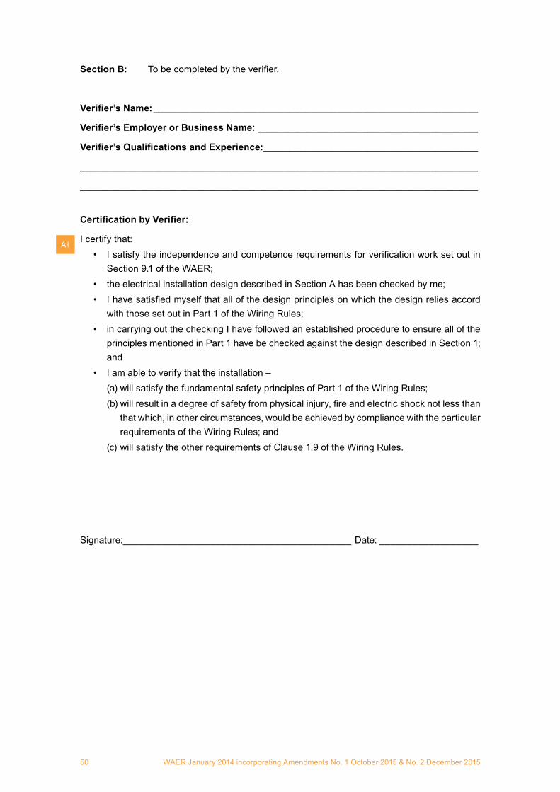
WAER January 2014 incorporating Amendments No. 1 October 2015 & No. 2 December 201550
Section B: To be completed by the verifier.
Verifier’sName: ______________________________________________________________
Verifier’sEmployerorBusinessName: __________________________________________
Verifier’sQualificationsandExperience: _________________________________________
____________________________________________________________________________
____________________________________________________________________________
CertificationbyVerifier:
I certify that:• I satisfy the independence and competence requirements for verification work set out in
Section 9.1 of the WAER;• the electrical installation design described in Section A has been checked by me;• I have satisfied myself that all of the design principles on which the design relies accord
with those set out in Part 1 of the Wiring Rules;• in carrying out the checking I have followed an established procedure to ensure all of the
principles mentioned in Part 1 have be checked against the design described in Section 1; and
• I am able to verify that the installation –(a) will satisfy the fundamental safety principles of Part 1 of the Wiring Rules;(b) will result in a degree of safety from physical injury, fire and electric shock not less than
that which, in other circumstances, would be achieved by compliance with the particular requirements of the Wiring Rules; and
(c) will satisfy the other requirements of Clause 1.9 of the Wiring Rules.
Signature:__________________________________________ Date: __________________
A1
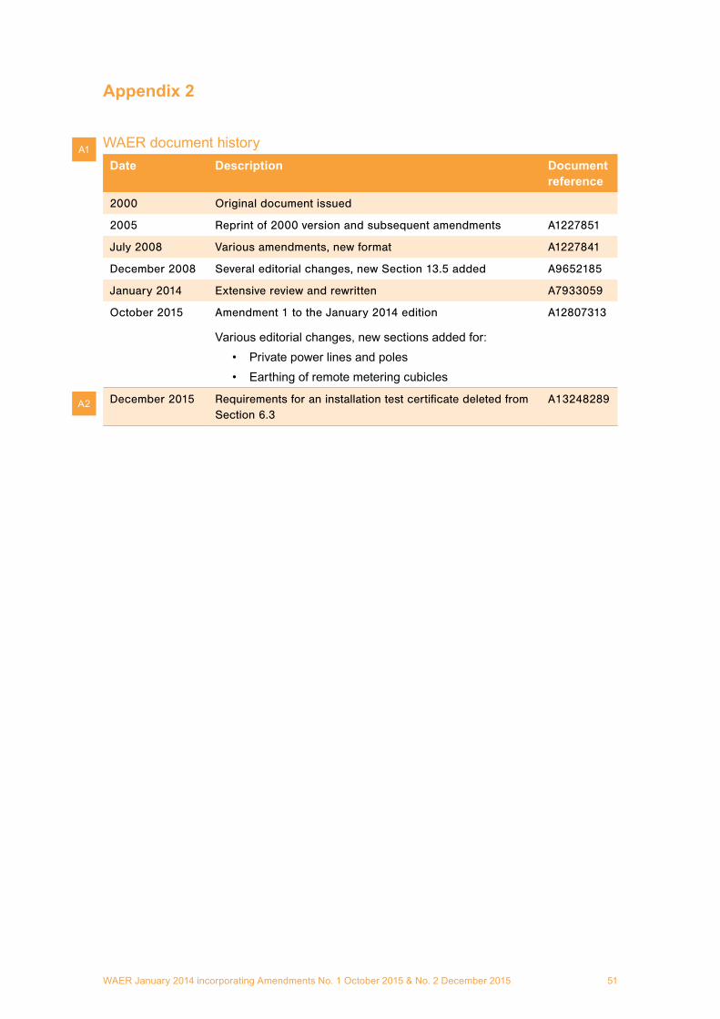
WAER January 2014 incorporating Amendments No. 1 October 2015 & No. 2 December 2015 51
Appendix 2
WAER document historyDate Description Document
reference
2000 Original document issued
2005 Reprint of 2000 version and subsequent amendments A1227851
July 2008 Various amendments, new format A1227841
December 2008 Several editorial changes, new Section 13.5 added A9652185
January 2014 Extensive review and rewritten A7933059
October 2015 Amendment 1 to the January 2014 edition
Various editorial changes, new sections added for:• Private power lines and poles• Earthing of remote metering cubicles
A12807313
December 2015 Requirements for an installation test certificate deleted from Section 6.3
A13248289
A1
A2

WAER January 2014 incorporating Amendments No. 1 October 2015 & No. 2 December 201552


ES
WA
E062 1215