W0GS18ST BMW R1200 GS 08 - Shad · 3 304070 2 Tornillo M6 x 40 DIN 912 - Screw - Vis - Schraube -...
2
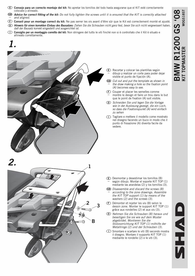
1 3 B 2 A Consejo para un correcto montaje del kit: No apretar los tornillos del todo hasta asegurarse que el KIT esté correctamente colocado y alineado. Advice for correct fitting of the kit: Do not fully tighten the screws until it is ensured that the KIT is correctly attached and aligned. Conseil pour un montage correct du kit: Ne pas serrer les vis avant d’être sûr que le Kit est correctement monté et ajusté. Hinweis für einen korrekten Einbau des Bausatzes: Ziehen Sie die Schrauben nicht ganz fest, bevor Sie sich nicht vergewissert haben, daß der Bausatz korrekt eingestellt und ausgerichtet ist. Consiglio per un montaggio corretto del kit: Non stringere del tutto le viti finché non si è controllato che il Kit è situato e allineato correttamente. BMW R1200 GS ‘08 KIT TOPMASTER W0GS18ST 2. 1. Recortar y colocar las plantillas según dibujo y realizar un corte para poder dejar visible el punto de fijación (A). Cut out and put the template as shown in the draw making a hole so the fixation point (A) becomes easy to see. Couper et placer les semelles comme montre le design et faire un trou dans le but que le point de fixation (A) soit visible. Schneiden Sie und legen Sie die Vorlage wie in der Auslosung gezeigt, die ein Loch, so dass die Fixationspunkt (A) wird einfach zu sehen Tagliare e mettere il modello come mostrato nel disegno facendo un buco in modo che il punto di fissazione (A) diventa facile da vedere. Desmontar y desestimar los tornillos (B) según dibujo. Montar el soporte KIT TOP (1) mediante las arandelas (2) y los tornillos (3). Disassemble and discard the screws (B) according to the zone drawings. Assemble the KIT TOP support (1) by means of the washers (2) and the screws (3). Démonter et rejeter les vis (B) selon le dessin zone. Monter le support KIT TOP (1) grâce aux rondelles (2) et aux vis (3). Nehmen Sie die Schrauben (B) heraus und beseitigen Sie sie wie auf dem Muster abgebildet. Montieren Sie die Stützvorrichtung KIT TOP (1) mithilfe der Metallringe (2) und der Schrauben (3). Smontare e scartare le viti (B) secondo mostra il disegno. Montare il supporto KIT TOP (1) mediante le rondelle (2) e le viti (3).
Transcript of W0GS18ST BMW R1200 GS 08 - Shad · 3 304070 2 Tornillo M6 x 40 DIN 912 - Screw - Vis - Schraube -...
1
3
B
2
A
Consejo para un correcto montaje del kit: No apretar los tornillos del todo hasta asegurarse que el KIT esté correctamentecolocado y alineado. Advice for correct fitting of the kit: Do not fully tighten the screws until it is ensured that the KIT is correctly attachedand aligned.Conseil pour un montage correct du kit: Ne pas serrer les vis avant d’être sûr que le Kit est correctement monté et ajusté.Hinweis für einen korrekten Einbau des Bausatzes: Ziehen Sie die Schrauben nicht ganz fest, bevor Sie sich nicht vergewissert haben,daß der Bausatz korrekt eingestellt und ausgerichtet ist. Consiglio per un montaggio corretto del kit: Non stringere del tutto le viti finché non si è controllato che il Kit è situato eallineato correttamente.
BM
W R
12
00
GS
‘08
K
IT T
OP
MA
STE
R
W0
GS
18
ST
2.
1.
Recortar y colocar las plantillas segúndibujo y realizar un corte para poder dejarvisible el punto de fijación (A).Cut out and put the template as shown inthe draw making a hole so the fixation point(A) becomes easy to see.Couper et placer les semelles commemontre le design et faire un trou dans le butque le point de fixation (A) soit visible.Schneiden Sie und legen Sie die Vorlagewie in der Auslosung gezeigt, die ein Loch,so dass die Fixationspunkt (A) wird einfachzu sehenTagliare e mettere il modello come mostratonel disegno facendo un buco in modo che ilpunto di fissazione (A) diventa facile davedere.
Desmontar y desestimar los tornillos (B)según dibujo. Montar el soporte KIT TOP (1)mediante las arandelas (2) y los tornillos (3). Disassemble and discard the screws (B)according to the zone drawings. Assemblethe KIT TOP support (1) by means of thewashers (2) and the screws (3). Démonter et rejeter les vis (B) selon ledessin zone. Monter le support KIT TOP (1)grâce aux rondelles (2) et aux vis (3).Nehmen Sie die Schrauben (B) heraus undbeseitigen Sie sie wie auf dem Musterabgebildet. Montieren Sie dieStützvorrichtung KIT TOP (1) mithilfe derMetallringe (2) und der Schrauben (3).Smontare e scartare le viti (B) secondo mostrail disegno. Montare il supporto KIT TOP (1)mediante le rondelle (2) e le viti (3).
1
2
4
72
65
88BM
W R
12
00
GS
‘08
K
IT T
OP
MA
STE
R
W0
GS
18
ST
REF. 500479Edición 3ª
Pos. Ref. Cant.
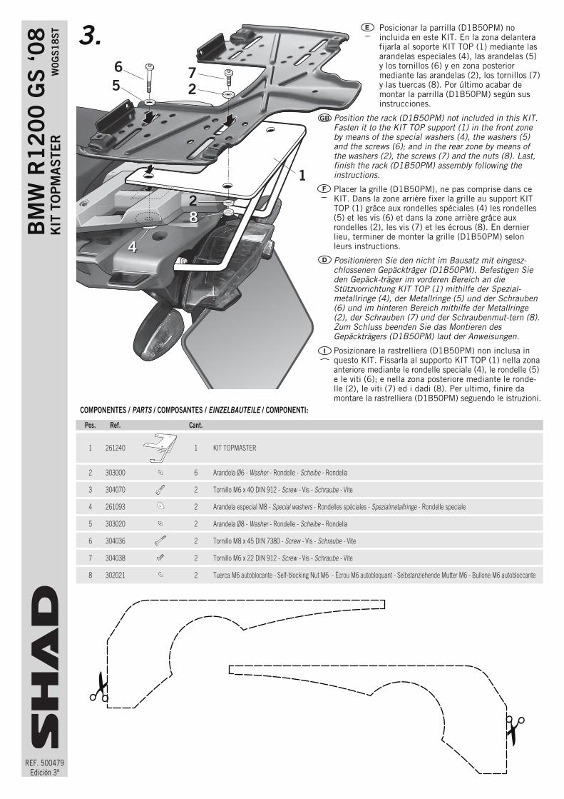
1 261240 1 KIT TOPMASTER
2 303000 6 Arandela Ø6 - Washer - Rondelle - Scheibe - Rondella
3 304070 2 Tornillo M6 x 40 DIN 912 - Screw - Vis - Schraube - Vite
4 261093 2 Arandela especial M8 - Special washers - Rondelles spéciales - Spezialmetallringe - Rondelle speciale
5 303020 2 Arandela Ø8 - Washer - Rondelle - Scheibe - Rondella
6 304036 2 Tornillo M8 x 45 DIN 7380 - Screw - Vis - Schraube - Vite
7 304038 2 Tornillo M6 x 22 DIN 912 - Screw - Vis - Schraube - Vite
8 302021 2 Tuerca M6 autoblocante - Self-blocking Nut M6 - Écrou M6 autobloquant - Selbstanziehende Mutter M6 - Bullone M6 autobloccante
COMPONENTES / PARTS / COMPOSANTES / EINZELBAUTEILE / COMPONENTI:
3. Posicionar la parrilla (D1B50PM) noincluida en este KIT. En la zona delanterafijarla al soporte KIT TOP (1) mediante lasarandelas especiales (4), las arandelas (5)y los tornillos (6) y en zona posteriormediante las arandelas (2), los tornillos (7)y las tuercas (8). Por último acabar demontar la parrilla (D1B50PM) según susinstrucciones.
Position the rack (D1B50PM) not included in this KIT.Fasten it to the KIT TOP support (1) in the front zoneby means of the special washers (4), the washers (5)and the screws (6); and in the rear zone by means ofthe washers (2), the screws (7) and the nuts (8). Last,finish the rack (D1B50PM) assembly following theinstructions.
Placer la grille (D1B50PM), ne pas comprise dans ceKIT. Dans la zone arrière fixer la grille au support KITTOP (1) grâce aux rondelles spéciales (4) les rondelles(5) et les vis (6) et dans la zone arrière grâce auxrondelles (2), les vis (7) et les écrous (8). En dernierlieu, terminer de monter la grille (D1B50PM) selonleurs instructions.
Positionieren Sie den nicht im Bausatz mit eingesz-chlossenen Gepäckträger (D1B50PM). Befestigen Sieden Gepäck-träger im vorderen Bereich an dieStützvorrichtung KIT TOP (1) mithilfe der Spezial-metallringe (4), der Metallringe (5) und der Schrauben(6) und im hinteren Bereich mithilfe der Metallringe(2), der Schrauben (7) und der Schraubenmut-tern (8).Zum Schluss beenden Sie das Montieren desGepäckträgers (D1B50PM) laut der Anweisungen.
Posizionare la rastrelliera (D1B50PM) non inclusa inquesto KIT. Fissarla al supporto KIT TOP (1) nella zonaanteriore mediante le rondelle speciale (4), le rondelle (5)e le viti (6); e nella zona posteriore mediante le ronde-lle (2), le viti (7) ed i dadi (8). Per ultimo, finire damontare la rastrelliera (D1B50PM) seguendo le istruzioni.
!!