W0224-001A APOLLO CRADLES LTD 1.5M X-BEAM 2016 DESIGN ...
57
AWD016-01 Rev 1 By EMcG 16-01-2016 W0224-001A APOLLO CRADLES LTD 1.5M X-BEAM 2016 DESIGN CHECK CALCULATIONS Alan N White B.Sc., M.Eng., C.Eng., M.I.C.E., M.I.H.T. Malachy Ryan B.Eng, M.Sc., C.Eng., M.I.C.E. DEC 2016 17-19 Hill Street Kilmarnock KA3 1HA Tel:01563 594 621 Fax:01563 593 056 [email protected]
Transcript of W0224-001A APOLLO CRADLES LTD 1.5M X-BEAM 2016 DESIGN ...

AWD016-01 Rev 1 By EMcG 16-01-2016
W0224-001A APOLLO CRADLES LTD 1.5M X-BEAM 2016 DESIGN CHECK CALCULATIONS
Alan N White B.Sc., M.Eng., C.Eng., M.I.C.E., M.I.H.T.
Malachy Ryan B.Eng, M.Sc., C.Eng., M.I.C.E.
DEC 2016
17-19 Hill Street Kilmarnock KA3 1HA Tel:01563 594 621 Fax:01563 593 056

AWD016-01 Rev 1 By EMcG 16-01-2016
Document Revision History
Revision Description Author Revision Date Checked
A Initial Issue MRB 07/12/2016 MMR
Project : Apollo 1.5m X-beam 2016Element : BriefJob Number : W0224 By : mrb Date: Dec 16Document No : 001A Checked: mmr Date: Dec 16
Brief The brief is to prepare calculated values for the capacity of the Apollo 1.5m X-Beam to BS EN 1999-1-1.
The beams are manufactured from tube extrusions in aluminium alloy6082 T6.
Alloy The alloy used is 6082 T6:
For extruded profiles/tubes with thickness less than 5mm:
Po,haz = 0.50
Pu,haz = 0.64
Fo = 250 N/mm2
Fu = 290 N/mm2
For extruded profiles/tubes with thickness greater than 5mm:
Po,haz = 0.48
Pu,haz = 0.60
Fo = 260 N/mm2
Fu = 310 N/mm2
Layout All beam lengths define the overall length of beam and not the span. As the
beam is supported at the verticals, all spans are 1m less than the beam length.
The geometry of the beam is shown in the drawing below:
Design Eurocode 9: Design of Aluminium structures EN 1999-1-1
Alloy used is 6082 T6 throughout
Design Assumptions
6082 T6 Aluminium is to be utilised throughout.
X-beam top and bottom booms are to be restrained at 1.00m c/c's.
All loads are to be applied at node locations.

Project : Apollo 1.5m X-beam 2016Element : BriefJob Number : W0224 By : mrb Date: Dec 16Document No : 001A Checked: mmr Date: Dec 16
Load Cases Images are shown for a 3m beam, loading for larger beams is applied using the same methodology.
Load Case 1 Self WeightSelf weight of all members factored by 1.15 to account for connections
Load Case 2 UDL10kN/m Load Applied to top boom over full length of the X-Beam at node points
Load Case 3 Central Point Load10kN Point Load Applied to Centre of Top Boom of the X-Beam

Project : Apollo 1.5m X-beam 2016Element : BriefJob Number : W0224 By : mrb Date: Dec 16Document No : 001A Checked: mmr Date: Dec 16
Load Case 4 Two Point Loads 2No 10kN point loads applied at third points along the top boom of the X-Beam.
Load Case 5 Three Point Loads3No 10kN Point Loads applied at quarter points along the X-Beam
Load Case 6 End Shear10kN Point Load applied 1.0m from support

Project : Apollo 1.5m X-beam 2016Element : BriefJob Number : W0224 By : mrb Date: Dec 16Document No : 001A Checked: mmr Date: Dec 16
Load Combinations
Combination Number Load Cases
1 1+22 1+33 1+44 1+55 1+6
Above Combinations were checked for the following design factors:
gD= 1.35
gL= 1.50
Combination DescriptionUDL
Central Point LoadTwo Point Loads
Three Point LoadsEnd Shear

Project : Apollo 1.5m X-beam 2016Element : Main Boom CapacityJob Number : W0224 By : mrb Date: Dec 16Document No : 001A Checked: mmr Date: Dec 16
Main Boom Capacity101.6 x 101.6 x 6.35mm SHS 6082-T2
Alu. 6082-T2 Po,haz = 0.48 (Table 3.2b)
Pu,haz = 0.60
fo = 260 N/mm2
fu = 310 N/mm2
101.6mm
101.6mm 88.9mm
6.35mmA= 2419 mm2
I= 3674543 mm4
Wel= 72334 mm3
Wpl= 86800 mm3
ry= 38.97 mm
for slenderness b= b/t b= 101.60 mm = 16.00 t = 6.35 mm
e= sqrt(250/fo) fo= 260 N/mm2
= 0.98
Class A, without welds, Internal parts b1= 11e
= 11*0.98 = 10.78< 16.00
b2= 16e
= 16*0.98 = 15.68< 16.00
Alan white design

Project : Apollo 1.5m X-beam 2016Element : Main Boom CapacityJob Number : W0224 By : mrb Date: Dec 16Document No : 001A Checked: mmr Date: Dec 16 Alan white design
b3= 22e
= 22*0.98 = 21.56> 16.00
Main Boom HAZ
There are HAZ's at welded joints to the diagonal and vertical.HAZ Section at diagonal not considered as Vertical HAZ is more detrimental
Two HAZ sections considered at the vertical, one at the edge of the vertical (A-A)and one through the mid-section of the vertical (B-B).
A B Vertical Member
Main Boom
Extent of HAZ
A BPLAN VIEW OF VERTICAL TO MAIN BOOM CONNECTION
Take sections shown below as heat affected
SHS Po,haz HAZ Section Layout
Section A-A Section B-B
Section is class 3

Project : Apollo 1.5m X-beam 2016Element : Main Boom CapacityJob Number : W0224 By : mrb Date: Dec 16Document No : 001A Checked: mmr Date: Dec 16 Alan white design
A-A B-BA= 1748.0 2290.2 mm2
I= 3097368.8 3444575.0 mm4
Wel,PoHAZ= 65207.8 72517.4 mm3
Wpl,PoHAZ= 78249.3 87020.8 mm3
ry= 42.1 38.8 mm
Conservatively, use section A-A as HAZ section properties are lower.
SHS Pu,haz HAZ Section Layout
Section A-A Section B-B
A-A B-BA= 1903.0 2384.6 mm2
I= 3230562.0 3569613.0 mm4
Wel,PuHAZ= 66940.8 73966.3 mm3
Wpl,PuHAZ= 80328.9 88759.5 mm3
ry= 41.2 38.7 mm
Conservatively, use section A-A as HAZ section properties are lower.
Boom SHS Moment Capacity (6.2.5.1)
Non-HAZMo,Rd = aWel fo / gM1
a3,u = 1.00 (Table 6.4)
Wel = 72.33 cm3
fo = 260 N/mm2
gM1 = 1.1 (6.1.3) = 1.00*72.33*260/1100
Mo,Rd = 17.10 kNm

Project : Apollo 1.5m X-beam 2016Element : Main Boom CapacityJob Number : W0224 By : mrb Date: Dec 16Document No : 001A Checked: mmr Date: Dec 16 Alan white design
HAZMu,Rd = Wnet fu / gM2
Wnet = Wel,PuHAZ
= 66.94 cm3
fu = 310 N/mm2
gM2 = 1.25 (6.1.3) = 66.94*310/1250
Mu,Rd = 16.60 kNm
MRd,x = 16.60 kNm lesser value of Mc,Rd / Mu,Rd
Boom SHS Shear Capacity (6.2.6)
VRd = Av fo/ √3gM1
Av= 0.6Ae
Av= 0.6*1748
Av= 1,048.80 mm2
gM1= 1.1fo = 260 N/mm2
= 1048.80*260/(SQRT(3)*1100)VRd = 143.12 kN

Project : Apollo 1.5m X-beam 2016Element : Main Boom CapacityJob Number : W0224 By : mrb Date: Dec 16Document No : 001A Checked: mmr Date: Dec 16 Alan white design
Boom SHS Axial Comp Capacity @ 1000mm (effective length of beam between restraints)
Without Weld Nb,Rd = kXwx Aeff fo /gM1 (6.3.1.1 (6.49a))
Ncr = π2 EI / k2 L2 (Appendix I.3)
E = 70,000 N/mm2
I = 3,674,543 mm4
k = 0.50L = 1,000 mm
Ncr = ((PI()^2)*70000*3674543)/((0.5^2)*(1000^2))= 10,154,560.01 N
λ = √Aeff fo / Ncr (6.3.1.2)
= 0.25 Aeff = 2419 mm2
A = 2,419 mm2
X = 1/ Φ+√Φ2-λ2
Φ = 0.5(1+ά(λ-λo)+λ2)
ά = 0.20 Table 6.6λo= 0.10 Table 6.6Φ = 0.55
X = 0.92
k= 1.00 (no welds)
wx= 1/(X+(1-X)sin(PI()xs/lcr))
= 1.08
Nb,Rd = 1.00*0.92*1.08*2419*260/1100= 568.10 kN

Project : Apollo 1.5m X-beam 2016Element : Main Boom CapacityJob Number : W0224 By : mrb Date: Dec 16Document No : 001A Checked: mmr Date: Dec 16 Alan white design
Localised Weld Nb,Rd = Xhazwx,haz Au,eff fu /gM2 (6.3.1.1 (6.49b))
Ncr = π2 EI / k2 L2 (Appendix I.3)
E = 70,000 N/mm2
I = 3,674,543 mm4
k = 0.50L = 1,000 mm
Ncr = ((PI()^2)*70000*3674543)/((0.5^2)*(1000^2))= 10,154,560.01 N
λhaz = √Au,eff fu / Ncr (6.3.1.2)= 0.23
Au,eff = 1903 mm2
A = 2,419 mm2
X = 1/ Φ+√Φ2-λ2
Φ = 0.5(1+ά(λ-λo)+λ2)
ά = 0.20 Table 6.6λo= 0.10 Table 6.6Φ = 0.54
X = 0.94
wx,haz = 1/(Xhaz+(1-Xhaz)sin(PI()xs,haz/lcr))
= 1.06
Nb,Rd = 0.94*1.06*1903*310/1250= 470.25 kN
Lesser Value= 470.25 kN

Project : Apollo 1.5m X-beam 2016Element : Main Boom CapacityJob Number : W0224 By : mrb Date: Dec 16Document No : 001A Checked: mmr Date: Dec 16 Alan white design
SHS Axial Tension Capacity (6.2.3)
1. General yieldingNo,Rd = Ag fo /gM1
fo = 260 N/mm2
Ag = A
= 2419 mm2
gM1 = 1.1 = 2419*260/1100 = 571.76 kN
2. Local failureNu,Rd = Au,efffu /gM2
fu = 310 N/mm2
Au,eff = 1903 mm2
gM1 = 1.25
= 1903*310/1250 = 471.94 kN
Lesser Value= 471.94 kN

Project : Apollo 1.5m X-beam 2016Element : Vertical CHS Member CapacityJob Number : W0224 By : mrb Date: Dec 16Document No : 001A Checked: mmr Date: Dec 16
Vertical CHS Member Capacityø48.3mm x 4.4mm CHS 6082-T6
Alu. 6082-T2 Po,haz = 0.50 (Table 3.2b)
Pu,haz = 0.64
fo = 250 N/mm2
fu = 290 N/mm2
Section Properties A= 607 mm2
I= 147654 mm4
Wel= 6114 mm3
Wpl= 8254 mm3
ry= 15.6 mm
for slenderness b= b/t b= 48.3 mm = 10.98 t = 4.4 mm
e= sqrt(250/fo) fo= 250 N/mm2
= 1.00
Class A, without welds, Internal parts b1= 11e
= 11*1.0 = 11.00> 10.98
Vertical CHS HAZ Length
Full perimeter weld at the joint, therefore the entire section is affected by HAZ.
As per BS EN 1999-1-1, for HAZ wall thickness factored by 0.50 (For Po,haz)
As per BS EN 1999-1-1, for HAZ wall thickness factored by 0.64 (For Pu,haz)
Section is class 1
Alan white design

Project : Apollo 1.5m X-beam 2016Element : Vertical CHS Member CapacityJob Number : W0224 By : mrb Date: Dec 16Document No : 001A Checked: mmr Date: Dec 16 Alan white design
Vertical CHS Po,haz HAZ Section Layout
Ahaz= 288 mm2
I= 62820 mm4
Iz= 62820 mm4
Wel,PoHAZ= 2,862 mm3
Wpl,PoHAZ= 3,864 mm3
Vertical CHS Pu,haz HAZ Section Layout
Ahaz= 374 mm2
I= 84308 mm4
Iz= 84308 mm4
Wel,PuHAZ= 3,735 mm3
Wpl,PuHAZ= 5,043 mm3

Project : Apollo 1.5m X-beam 2016Element : Vertical CHS Member CapacityJob Number : W0224 By : mrb Date: Dec 16Document No : 001A Checked: mmr Date: Dec 16 Alan white design
Vertical CHS Moment Capacity (6.2.5.1)
Non-HAZMo,Rd = aWel fo / gM1
a = Wpl/Wel (Table 6.4)= 1.35
Wel = 6.11 cm3
fo = 250 N/mm2
gM1 = 1.1 (6.1.3) = 1.35*6.11*250/1100
Mo,Rd = 1.87 kNm
HAZMu,Rd = Wnet fu / gM2
Wnet = Wel,PuHAZ
= 3.74 cm3
fu = 290 N/mm2
gM2 = 1.25 (6.1.3) = 3.74*290/1250
Mu,Rd = 0.87 kNm
MRd,x = 0.87 kNm lesser value of Mc,Rd / Mu,Rd
Vertical CHS Shear Capacity (6.2.6)
VRd = Av fo/ √3gM1
Av= 0.6Ae
Av= 0.6*288
Av= 172.80 mm2
gM1= 1.1fo = 250 N/mm2
= 172.80*250/(SQRT(3)*1100)VRd = 22.67 kN

Project : Apollo 1.5m X-beam 2016Element : Vertical CHS Member CapacityJob Number : W0224 By : mrb Date: Dec 16Document No : 001A Checked: mmr Date: Dec 16 Alan white design
Vertical CHS Axial Comp Capacity @ 1297mm (effective length of beam)
Without Weld Nb,Rd = kXwx Aeff fo /gM1 (6.3.1.1 (6.49a))
Ncr = π2 EI / k2 L2 (Appendix I.3)
E = 70,000 N/mm2
I = 147,654 mm4
k = 0.50L = 1,297 mm
Ncr = ((PI()^2)*70000*147654)/((0.5^2)*(1297^2))= 242,562.15 N
λ = √Aeff fo / Ncr (6.3.1.2)
= 0.79 Aeff = 607 mm2
A = 607 mm2
X = 1/ Φ+√Φ2-λ2
Φ = 0.5(1+ά(λ-λo)+λ2)
ά = 0.20 Table 6.6λo= 0.10 Table 6.6Φ = 0.88
X = 0.57
k= 1.00 (no welds)
wx= 1/(X+(1-X)sin(PI()xs/lcr))
= 1.69
Nb,Rd = 1.00*0.57*1.69*607*250/1100= 132.89 kN

Project : Apollo 1.5m X-beam 2016Element : Vertical CHS Member CapacityJob Number : W0224 By : mrb Date: Dec 16Document No : 001A Checked: mmr Date: Dec 16 Alan white design
Localised Weld Nb,Rd = Xhazwx,haz Au,eff fu /gM2 (6.3.1.1 (6.49b))
Ncr = π2 EI / k2 L2 (Appendix I.3)
E = 70,000 N/mm2
I = 147,654 mm4
k = 0.50L = 1,297 mm
Ncr = ((PI()^2)*70000*147654)/((0.5^2)*(1297^2))= 242,562.15 N
λhaz = √Au,eff fu / Ncr (6.3.1.2)= 0.63
Au,eff = 374 mm2
A = 607 mm2
X = 1/ Φ+√Φ2-λ2
Φ = 0.5(1+ά(λ-λo)+λ2)
ά = 0.20 Table 6.6λo= 0.10 Table 6.6Φ = 0.75
X = 0.67
wx,haz = 1/(Xhaz+(1-Xhaz)sin(PI()xs,haz/lcr))
= 1.45
Nb,Rd = 0.67*1.45*374*290/1250= 84.30 kN
Lesser Value= 84.30 kN

Project : Apollo 1.5m X-beam 2016Element : Vertical CHS Member CapacityJob Number : W0224 By : mrb Date: Dec 16Document No : 001A Checked: mmr Date: Dec 16 Alan white design
Vertical CHS Axial Tension Capacity (6.2.3)
1. General yieldingNo,Rd = Ag fo /gM1
fo = 250 N/mm2
Ag = A
= 607 mm2
gM1 = 1.1 = 607*250/1100 = 137.95 kN
2. Local failureNu,Rd = Au,efffu /gM2
fu = 290 N/mm2
Au,eff = 374 mm2
gM1 = 1.25
= 374*290/1250 = 86.77 kN
Lesser Value= 86.77 kN

Project : Apollo 1.5m X-beam 2016Element : SHS Diagonal CapacityJob Number : W0224 By : mrb Date: Dec 16Document No : 001A Checked: mmr Date: Dec 16
SHS Diagonal Layout50.8 x 50.8 x 3mm SHS 6082-T2
Alu. 6082-T2 Po,haz = 0.50 (Table 3.2b)
Pu,haz = 0.64
fo = 250 N/mm2
fu = 290 N/mm2
50.8mm
50.8mm 44.8mm
3.00mmA= 574 mm2
I= 219291 mm4
Wel= 8634 mm3
Wpl= 10360 mm3
ry= 19.55 mm
for slenderness b= b/t b= 50.80 mm = 16.93 t = 3.00 mm
e= sqrt(250/fo) fo= 250 N/mm2
= 1.00
Class A, without welds, Internal parts b1= 11e
= 11*1.00 = 11.00< 16.93
b2= 16e
= 16*1.00 = 16.00< 16.93
Alan white design
Page 18of 22

Project : Apollo 1.5m X-beam 2016Element : SHS Diagonal CapacityJob Number : W0224 By : mrb Date: Dec 16Document No : 001A Checked: mmr Date: Dec 16 Alan white design
b3= 22e
= 22*1.00 = 22.00> 16.93
SHS Diagonal HAZ Length
Full perimeter weld at the joint, therefore the entire section is affected by HAZ.
As per BS EN 1999-1-1, for HAZ wall thickness factored by 0.50 (For Po,haz)
As per BS EN 1999-1-1, for HAZ wall thickness factored by 0.64 (For Pu,haz)
SHS Diagonal Po,haz HAZ Section Layout
47.8mm
44.8mm
1.5mm
Ahaz= 278 mm2
I= 99357 mm4
Iz= 99357 mm4
Wel,PoHAZ= 4,157 mm3
Wpl,PoHAZ= 4,989 mm3
Section is class 3
Page 19of 22

Project : Apollo 1.5m X-beam 2016Element : SHS Diagonal CapacityJob Number : W0224 By : mrb Date: Dec 16Document No : 001A Checked: mmr Date: Dec 16 Alan white design
SHS Diagonal Pu,haz HAZ Section Layout
46.96mm
44.8mm
1.92mm
Ahaz= 358 mm2
I= 130752 mm4
Iz= 130752 mm4
Wel,PuHAZ= 5,376 mm3
Wpl,PuHAZ= 6,452 mm3
SHS Diagonal Axial Tension Capacity (6.2.3)
1. General yieldingNo,Rd = Ag fo /gM1
fo = 250 N/mm2
Ag = A
= 574 mm2
gM1 = 1.1 = 574*250/1100 = 130.45 kN
2. Local failureNu,Rd = Au,efffu /gM2
fu = 290 N/mm2
Au,eff = 358 mm2
gM1 = 1.25
= 358*290/1250 = 83.06 kN
Lesser Value= 83.06 kN
Page 20of 22

Project : Apollo 1.5m X-beam 2016Element : SHS Diagonal CapacityJob Number : W0224 By : mrb Date: Dec 16Document No : 001A Checked: mmr Date: Dec 16 Alan white design
SHS Diagonal Axial Comp Capacity @ 732mm (effective length of beam)
Without Weld Nb,Rd = kXwx Aeff fo /gM1 (6.3.1.1 (6.49a))
Ncr = π2 EI / k2 L2 (Appendix I.3)
E = 70,000 N/mm2
I = 219,291 mm4
k = 0.50L = 732 mm
Ncr = ((PI()^2)*70000*219291)/((0.5^2)*(732^2))= 1,130,983.90 N
λ = √Aeff fo / Ncr (6.3.1.2)
= 0.36 Aeff = 574 mm2
A = 574 mm2
X = 1/ Φ+√Φ2-λ2
Φ = 0.5(1+ά(λ-λo)+λ2)
ά = 0.20 Table 6.6λo= 0.10 Table 6.6Φ = 0.59
X = 0.86
k= 1.00 (no welds)
wx= 1/(X+(1-X)sin(PI()xs/lcr))
= 1.16
Nb,Rd = 1.00*0.86*1.16*574*250/1100= 130.14 kN
Page 21of 22
Project : Apollo 1.5m X-beam 2016Element : SHS Diagonal CapacityJob Number : W0224 By : mrb Date: Dec 16Document No : 001A Checked: mmr Date: Dec 16 Alan white design
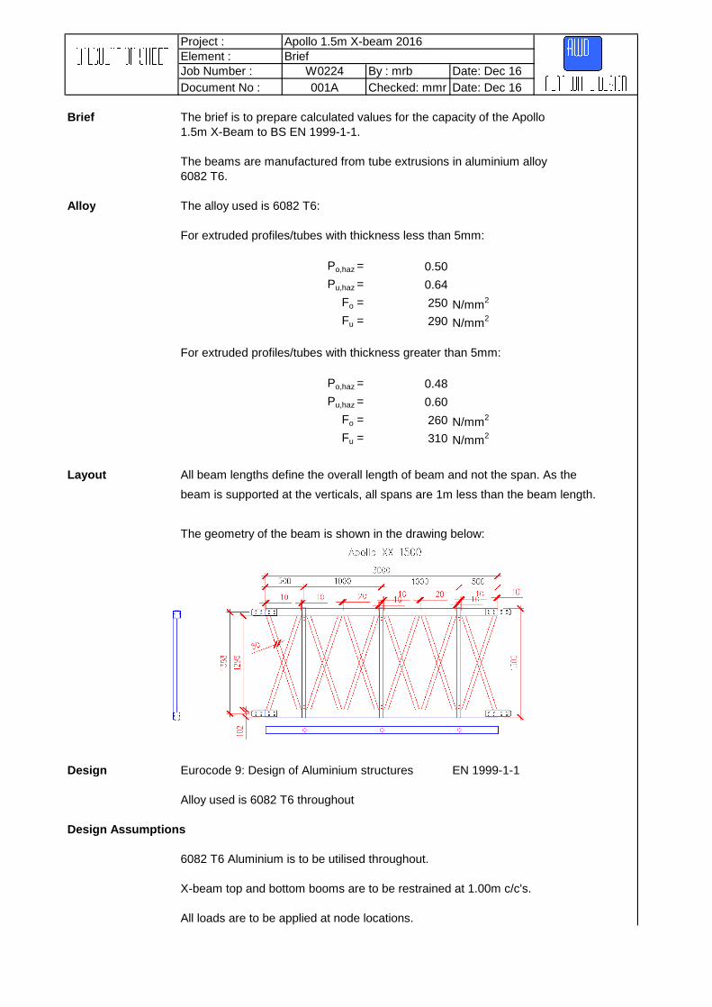
Localised Weld Nb,Rd = Xhazwx,haz Au,eff fu /gM2 (6.3.1.1 (6.49b))
Ncr = π2 EI / k2 L2 (Appendix I.3)
E = 70,000 N/mm2
I = 219,291 mm4
k = 0.50L = 732 mm
Ncr = ((PI()^2)*70000*219291)/((0.5^2)*(732^2))= 1,130,983.90 N
λhaz = √Au,eff fu / Ncr (6.3.1.2)= 0.28
Au,eff = 358 mm2
A = 574 mm2
X = 1/ Φ+√Φ2-λ2
Φ = 0.5(1+ά(λ-λo)+λ2)
ά = 0.20 Table 6.6λo= 0.10 Table 6.6Φ = 0.56
X = 0.90
wx,haz = 1/(Xhaz+(1-Xhaz)sin(PI()xs,haz/lcr))
= 1.10
Nb,Rd = 0.90*1.10*358*290/1250= 82.23 kN
Lesser Value= 82.23 kN
Page 22of 22

Project : Apollo 1.5m X-beam 2016Element : 12m X-Beam ResultsJob Number : W0224 By : mrb Date: Dec 16Document No : 001A Checked: mmr Date: Dec 16
12m X-Beam Results
Alan white design

Project : Apollo 1.5m X-beam 2016Element : 12m X-Beam Load Combination 1Job Number : W0224 By : mrb Date: Dec 16Document No : 001A Checked: mmr Date: Dec 16
Load Comb. 1 UDL load 10kN/m applied along beam
Element Action Formula Ultimate Calculated Factor
Boom Moment Mc,Rd 16.60 3.72 4.47
Shear VRd 143.12 9.77 14.66
Tension No,Rd 471.94 54.37 8.68
Compression Nb,Rd 470.25 164.18 2.86Deflection d 120.00 17.80 6.74Combined (Ned/NRd)
1.3 + [(Med,x/Mrd,x)
1.7]0.6 < 1.0 1.00 1.89
Vertical Moment Mc,Rd 0.87 0.13 6.89
Shear VRd 22.67 0.18 128.83
Tension No,Rd 86.77 0.75 115.85
Compression Nb,Rd 84.30 25.07 3.36Combined (Ned/NRd)
1.3 + [(Med,x/Mrd,x)
1.7]0.6 < 1.0 1.00 2.43
Diagonal Tension No,Rd 83.06 38.11 2.18
Compression Nb,Rd 82.23 49.46 1.66Factor 1.66
Ra Rb
Max Moment= WL2/8
so for ultimate condition W= 1.5*10
15.00 kNapply factor from above
Wf= 15*1.66= 24.90 kN
so maximum moment is as above Ultimate Mu= Wf*12^2/8
= (24.90*12^2)/8= 448.20 kNm
and for allowable valueallowable max moment= 448.20/1.50
= 298.80 kNm
Moment values Ultimate 448.20 kNmAllowable 298.80 kNm
12.00m
Alan white design
w w

Project : Apollo 1.5m X-beam 2016Element : 12m X-Beam Load Combination 2Job Number : W0224 By : mrb Date: Dec 16Document No : 001A Checked: mmr Date: Dec 16
Load Comb. 2 Point load 10kN load applied at midspan of beam
Element Action Formula Ultimate Calculated Factor
Boom Moment Mc,Rd 16.60 0.80 20.67
Shear VRd 143.12 2.03 70.64
Tension No,Rd 471.94 15.20 31.05
Compression Nb,Rd 470.25 30.73 15.30Deflection d 120.00 3.34 35.93Combined (Ned/NRd)
1.3 + [(Med,x/Mrd,x)
1.7]0.6 < 1.0 1.00 9.58
Vertical Moment Mc,Rd 0.87 0.02 51.04
Shear VRd 22.67 0.02 985.83
Tension No,Rd 86.77 0.53 165.27
Compression Nb,Rd 84.30 2.52 33.48Combined (Ned/NRd)
1.3 + [(Med,x/Mrd,x)
1.7]0.6 < 1.0 1.00 21.94
Diagonal Tension No,Rd 83.06 4.99 16.64
Compression Nb,Rd 82.23 5.90 13.95Factor 9.58
W 6.0m
Ra RbMax Moment= WL/4
so for ultimate condition W= 1.50*10
= 15.00 kNapply factor from above
Wf= 15*9.58= 143.70 kN
so maximum moment is as above Ultimate Mu= Wf*L/4
= 143.70*12/4= 431.10 kNm
and for allowable valueallowable max moment= 431.10/1.50
= 287.40 kNm
Moment values Ultimate 431.10 kNmAllowable 287.40 kNm
12.00m
Alan white design
Project : Apollo 1.5m X-beam 2016Element : 12m X-Beam Load Combination 3Job Number : W0224 By : mrb Date: Dec 16Document No : 001A Checked: mmr Date: Dec 16
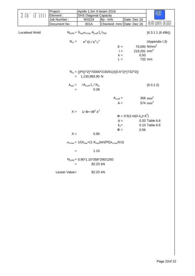
Load Comb. 3 PL at third points 10kN load applied at each of the two third points
Element Action Formula Ultimate Calculated Factor
Boom Moment Mc,Rd 16.60 0.80 20.73
Shear VRd 143.12 2.03 70.57
Tension No,Rd 471.94 13.03 36.22
Compression Nb,Rd 470.25 41.21 11.41Deflection d 120.00 4.52 26.55Combined Axial (Ned/NRd)
1.3 + [(Med,x/Mrd,x)
1.7]0.6 < 1.0 1.00 7.94
Vertical Moment Mc,Rd 0.87 0.03 27.12
Shear VRd 22.67 0.04 539.86
Tension No,Rd 86.77 0.63 138.83
Compression Nb,Rd 84.30 4.48 18.80Combined Axial (Ned/NRd)
1.3 + [(Med,x/Mrd,x)
1.7]0.6 < 1.0 1.00 12.07
Diagonal Tension No,Rd 83.06 9.06 9.17
Compression Nb,Rd 82.23 10.25 8.02Factor 7.94
4.0m W W 4.0m
Ra Rb
Max Moment= WL/3
so for ultimate condition W= 1.50*10
15.00 kNapply factor from above
Wf= 15.00*7.94= 119.10 kN
so maximum moment is as above Ultimate Mu= Wf*L/3
= (119.10*12)/3= 476.40 kNm
and for allowable valueallowable max moment= 476.40/1.50
= 317.60 kNm
Moment values Ultimate 476.40 kNmAllowable 317.60 kNm
12.00m
Alan white design
Project : Apollo 1.5m X-beam 2016Element : 12m X-Beam Load Combination 4Job Number : W0224 By : mrb Date: Dec 16Document No : 001A Checked: mmr Date: Dec 16
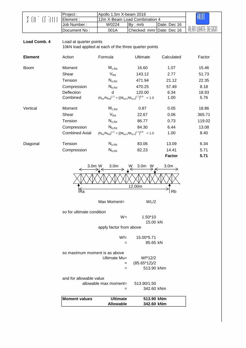
Load Comb. 4 Load at quarter points10kN load applied at each of the three quarter points
Element Action Formula Ultimate Calculated Factor
Boom Moment Mc,Rd 16.60 1.07 15.46
Shear VRd 143.12 2.77 51.73
Tension No,Rd 471.94 21.12 22.35
Compression Nb,Rd 470.25 57.49 8.18Deflection d 120.00 6.34 18.93Combined (Ned/NRd)
1.3 + [(Med,x/Mrd,x)
1.7]0.6 < 1.0 1.00 5.76
Vertical Moment Mc,Rd 0.87 0.05 18.86
Shear VRd 22.67 0.06 365.71
Tension No,Rd 86.77 0.73 119.02
Compression Nb,Rd 84.30 6.44 13.08Combined Axial (Ned/NRd)
1.3 + [(Med,x/Mrd,x)
1.7]0.6 < 1.0 1.00 8.40
Diagonal Tension No,Rd 83.06 13.09 6.34
Compression Nb,Rd 82.23 14.41 5.71Factor 5.71
3.0m W 3.0m W 3.0m W 3.0m
12.00m Ra Rb
Max Moment= WL/2
so for ultimate condition W= 1.50*10
15.00 kNapply factor from above
Wf= 15.00*5.71= 85.65 kN
so maximum moment is as above Ultimate Mu= Wf*12/2
= (85.65*12)/2= 513.90 kNm
and for allowable valueallowable max moment= 513.90/1.50
= 342.60 kNm
Moment values Ultimate 513.90 kNmAllowable 342.60 kNm
Alan white design

Project : Apollo 1.5m X-beam 2016Element : 12m X-Beam Load Combination 5Job Number : W0224 By : mrb Date: Dec 16Document No : 001A Checked: mmr Date: Dec 16
Load Comb. 5 End Shear 10kN load applied at a 1.0m distance from the support
Element Action Formula Ultimate Calculated Factor
Boom Moment Mc,Rd 16.60 0.69 23.99
Shear VRd 143.12 2.04 70.30
Tension No,Rd 471.94 3.76 125.52
Compression Nb,Rd 470.25 11.06 42.51Deflection d 120.00 1.08 111.11Combined (Ned/NRd)
1.3 + [(Med,x/Mrd,x)
1.7]0.6 < 1.0 1.00 16.88
Vertical Moment Mc,Rd 0.87 0.01 61.98
Shear VRd 22.67 0.02 1133.71
Tension No,Rd 86.77 0.24 364.57
Compression Nb,Rd 84.30 4.05 20.81Combined Axial (Ned/NRd)
1.3 + [(Med,x/Mrd,x)
1.7]0.6 < 1.0 1.00 16.50
Diagonal Tension No,Rd 83.06 6.25 13.29
Compression Nb,Rd 82.23 7.74 10.62Factor 10.62
W 1.0m
12.00m Ra Rb
Max Shear Rb= W*11/12
so for ultimate condition W= 1.50*10
15.00 kNapply factor from above
Wf= 15.0*10.62= 159.30 kN
so maximum shear is as above Ultimate Qu= Wf*11/12
= (159.30*11)/12= 146.03 kN
and for allowable valueallowable max shear= 146.03/1.50
= 97.35 kN
Shear values Ultimate 146.03 kNAllowable 97.35 kN
Alan white design
Project : Apollo 1.5m X-beam 2016Element : 12m X-Beam ResultsJob Number : W0224 By : mrb Date: Dec 16Document No : 001A Checked: mmr Date: Dec 16
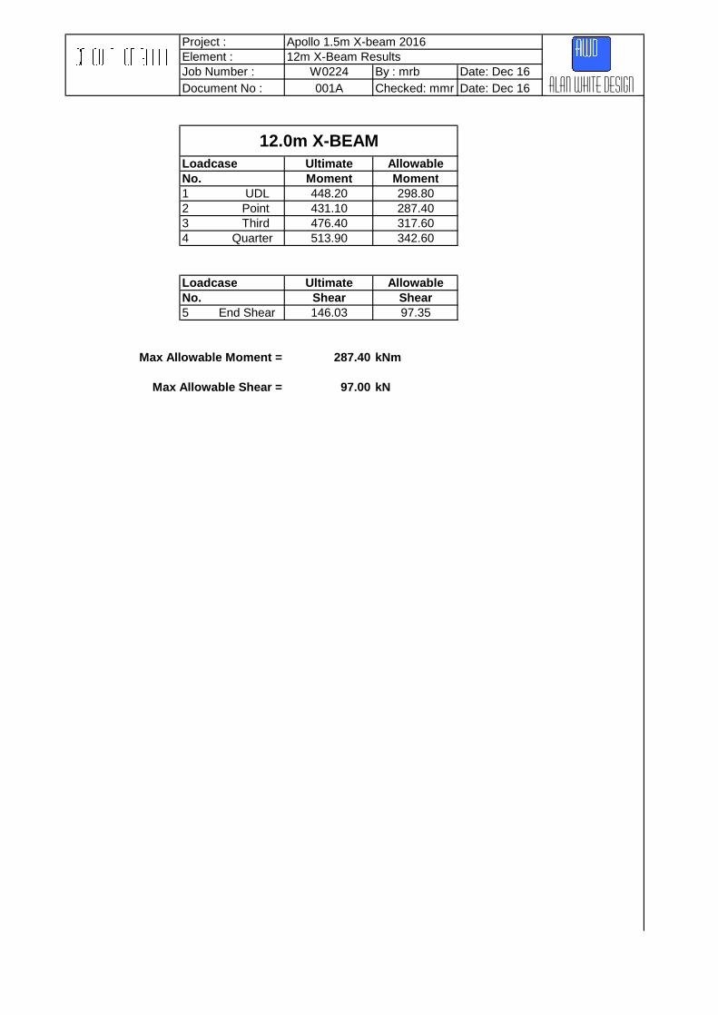
Loadcase Ultimate AllowableNo. Moment Moment1 UDL 448.20 298.802 Point 431.10 287.403 Third 476.40 317.604 Quarter 513.90 342.60
Loadcase Ultimate AllowableNo. Shear Shear5 End Shear 146.03 97.35
Max Allowable Moment = 287.40 kNm
Max Allowable Shear = 97.00 kN
12.0m X-BEAM
Alan white design
Project : Apollo 1.5m X-beam 2016Element : 18m X-Beam ResultsJob Number : W0224 By : mrb Date: Dec 16Document No : 001A Checked: mmr Date: Dec 16
18m X-Beam Results
Alan white design

Project : Apollo 1.5m X-beam 2016Element : 18m X-Beam Load Combination 1Job Number : W0224 By : mrb Date: Dec 16Document No : 001A Checked: mmr Date: Dec 16
Load Comb. 1 UDL load 10kN/m applied along beam
Element Action Formula Ultimate Calculated Factor
Boom Moment Mc,Rd 16.60 5.79 2.87
Shear VRd 143.12 14.93 9.59
Tension No,Rd 471.94 131.02 3.60
Compression Nb,Rd 470.25 394.20 1.19Deflection d 180.00 73.03 2.46Combined (Ned/NRd)
1.3 + [(Med,x/Mrd,x)
1.7]0.6 < 1.0 1.00 0.90
Vertical Moment Mc,Rd 0.87 0.21 4.13
Shear VRd 22.67 0.29 77.12
Tension No,Rd 86.77 2.67 32.50
Compression Nb,Rd 84.30 36.68 2.30Combined (Ned/NRd)
1.3 + [(Med,x/Mrd,x)
1.7]0.6 < 1.0 1.00 1.59
Diagonal Tension No,Rd 83.06 62.93 1.32
Compression Nb,Rd 82.23 76.78 1.07Factor 0.90
Ra Rb
Max Moment= WL2/8
so for ultimate condition W= 1.5*10
15.00 kNapply factor from above
Wf= 15*0.90= 13.50 kN
so maximum moment is as above Ultimate Mu= Wf*18^2/8
= (13.50*18^2)/8= 546.75 kNm
and for allowable valueallowable max moment= 546.75/1.50
= 364.50 kNm
Moment values Ultimate 546.75 kNmAllowable 364.50 kNm
18.00m
Alan white design
w w

Project : Apollo 1.5m X-beam 2016Element : 18m X-Beam Load Combination 2Job Number : W0224 By : mrb Date: Dec 16Document No : 001A Checked: mmr Date: Dec 16
Load Comb. 2 Point load 10kN load applied at midspan of beam
Element Action Formula Ultimate Calculated Factor
Boom Moment Mc,Rd 16.60 0.83 20.00
Shear VRd 143.12 2.00 71.56
Tension No,Rd 471.94 25.01 18.87
Compression Nb,Rd 470.25 52.07 9.03Deflection d 180.00 9.11 19.76Combined (Ned/NRd)
1.3 + [(Med,x/Mrd,x)
1.7]0.6 < 1.0 1.00 6.67
Vertical Moment Mc,Rd 0.87 0.02 48.20
Shear VRd 22.67 0.03 872.08
Tension No,Rd 86.77 0.40 215.84
Compression Nb,Rd 84.30 2.74 30.74Combined (Ned/NRd)
1.3 + [(Med,x/Mrd,x)
1.7]0.6 < 1.0 1.00 20.34
Diagonal Tension No,Rd 83.06 5.55 14.97
Compression Nb,Rd 82.23 6.12 13.44Factor 6.67
W 9.0m
Ra RbMax Moment= WL/4
so for ultimate condition W= 1.50*10
= 15.00 kNapply factor from above
Wf= 15*6.67= 100.05 kN
so maximum moment is as above Ultimate Mu= Wf*18/4
= 100.05*18/4= 450.23 kNm
and for allowable valueallowable max moment= 450.23/1.50
= 300.15 kNm
Moment values Ultimate 450.23 kNmAllowable 300.15 kNm
18.00m
Alan white design

Project : Apollo 1.5m X-beam 2016Element : 18m X-Beam Load Combination 3Job Number : W0224 By : mrb Date: Dec 16Document No : 001A Checked: mmr Date: Dec 16
Load Comb. 3 PL at third points 10kN load applied at each of the two third points
Element Action Formula Ultimate Calculated Factor
Boom Moment Mc,Rd 16.60 0.83 20.05
Shear VRd 143.12 2.05 69.68
Tension No,Rd 471.94 21.78 21.67
Compression Nb,Rd 470.25 67.91 6.92Deflection d 180.00 12.89 13.96Combined (Ned/NRd)
1.3 + [(Med,x/Mrd,x)
1.7]0.6 < 1.0 1.00 5.46
Vertical Moment Mc,Rd 0.87 0.03 27.12
Shear VRd 22.67 0.05 503.87
Tension No,Rd 86.77 0.79 109.83
Compression Nb,Rd 84.30 4.67 18.04Combined (Ned/NRd)
1.3 + [(Med,x/Mrd,x)
1.7]0.6 < 1.0 1.00 11.76
Diagonal Tension No,Rd 83.06 9.61 8.64
Compression Nb,Rd 82.23 10.59 7.76Factor 5.46
6.0m W W 6.0m
Ra Rb
Max Moment= WL/3
so for ultimate condition W= 1.50*10
15.00 kNapply factor from above
Wf= 15.00*5.46= 81.90 kN
so maximum moment is as above Ultimate Mu= Wf*L/3
= (81.90*18)/3= 491.40 kNm
and for allowable valueallowable max moment= 491.40/1.50
= 327.60 kNm
Moment values Ultimate 491.40 kNmAllowable 327.60 kNm
18.00m
Alan white design

Project : Apollo 1.5m X-beam 2016Element : 18m X-Beam Load Combination 4Job Number : W0224 By : mrb Date: Dec 16Document No : 001A Checked: mmr Date: Dec 16
Load Comb. 4 Load at quarter points10kN load applied at each of the three quarter points
Element Action Formula Ultimate Calculated Factor
Boom Moment Mc,Rd 16.60 1.14 14.60
Shear VRd 143.12 2.89 49.52
Tension No,Rd 471.94 35.02 13.48
Compression Nb,Rd 470.25 94.88 4.96Deflection d 180.00 17.50 10.29Combined (Ned/NRd)
1.3 + [(Med,x/Mrd,x)
1.7]0.6 < 1.0 1.00 3.92
Vertical Moment Mc,Rd 0.87 0.05 18.86
Shear VRd 22.67 0.06 354.28
Tension No,Rd 86.77 0.93 93.30
Compression Nb,Rd 84.30 6.61 12.75Combined (Ned/NRd)
1.3 + [(Med,x/Mrd,x)
1.7]0.6 < 1.0 1.00 8.26
Diagonal Tension No,Rd 83.06 13.60 6.11
Compression Nb,Rd 82.23 14.99 5.49Factor 3.92
4.50m W 4.50m W 4.50m W 4.50m
Ra Rb
Max Moment= WL/2
so for ultimate condition W= 1.50*10
15.00 kNapply factor from above
Wf= 15.00*3.92= 58.80 kN
so maximum moment is as above Ultimate Mu= Wf*L/2
= (58.80*18)/2= 529.20 kNm
and for allowable valueallowable max moment= 529.20/1.50
= 352.80 kNm
Moment values Ultimate 529.20 kNmAllowable 352.80 kNm
18.00m
Alan white design
Project : Apollo 1.5m X-beam 2016Element : 18m X-beam Load Combination 5Job Number : W0224 By : mrb Date: Dec 16Document No : 001A Checked: mmr Date: Dec 16
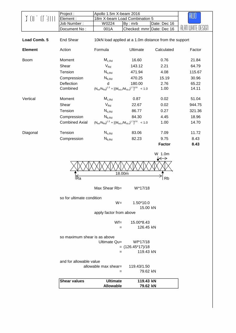
Load Comb. 5 End Shear 10kN load applied at a 1.0m distance from the support
Element Action Formula Ultimate Calculated Factor
Boom Moment Mc,Rd 16.60 0.76 21.84
Shear VRd 143.12 2.21 64.79
Tension No,Rd 471.94 4.08 115.67
Compression Nb,Rd 470.25 15.19 30.96Deflection d 180.00 2.76 65.22Combined (Ned/NRd)
1.3 + [(Med,x/Mrd,x)
1.7]0.6 < 1.0 1.00 14.11
Vertical Moment Mc,Rd 0.87 0.02 51.04
Shear VRd 22.67 0.02 944.75
Tension No,Rd 86.77 0.27 321.36
Compression Nb,Rd 84.30 4.45 18.96Combined Axial (Ned/NRd)
1.3 + [(Med,x/Mrd,x)
1.7]0.6 < 1.0 1.00 14.70
Diagonal Tension No,Rd 83.06 7.09 11.72
Compression Nb,Rd 82.23 9.75 8.43Factor 8.43
W 1.0m
Ra Rb
Max Shear Rb= W*17/18
so for ultimate condition W= 1.50*10.0
15.00 kNapply factor from above
Wf= 15.00*8.43= 126.45 kN
so maximum shear is as above Ultimate Qu= Wf*17/18
= (126.45*17)/18= 119.43 kN
and for allowable valueallowable max shear= 119.43/1.50
= 79.62 kN
Shear values Ultimate 119.43 kNAllowable 79.62 kN
18.00m
Alan white design

Project : Apollo 1.5m X-beam 2016Element : 18m X-Beam ResultsJob Number : W0224 By : mrb Date: Dec 16Document No : 001A Checked: mmr Date: Dec 16
Loadcase Ultimate AllowableNo. Moment Moment1 UDL 546.75 364.502 Point 450.23 300.153 Third 491.40 327.604 Quarter 529.20 352.80
Loadcase Ultimate AllowableNo. Shear Shear5 End Shear 119.43 79.62
Max Allowable Moment = 300.00 kNm
Max Allowable Shear = 79.50 kN
18.0m X-BEAM
Alan white design

Project : Apollo 1.5m X-beam 2016Element : 24m X-Beam ResultsJob Number : W0224 By : mrb Date: Dec 16Document No : 001A Checked: mmr Date: Dec 16
24m X-Beam Results
Alan white design

Project : Apollo 1.5m X-beam 2016Element : 24m X-Beam ResultsJob Number : W0224 By : mrb Date: Dec 16Document No : 001A Checked: mmr Date: Dec 16
Load Comb. 1 UDL load 10kN/m applied along beam
Element Action Formula Ultimate Calculated Factor
Boom Moment Mc,Rd 16.60 7.91 2.10
Shear VRd 143.12 20.15 7.10
Tension No,Rd 471.94 240.51 1.96
Compression Nb,Rd 470.25 722.81 0.65Deflection d 240.00 213.85 1.12Combined (Ned/NRd)
1.3 + [(Med,x/Mrd,x)
1.7]0.6 < 1.0 1.00 0.52
Vertical Moment Mc,Rd 0.87 0.29 2.96
Shear VRd 22.67 0.41 55.03
Tension No,Rd 86.77 5.19 16.72
Compression Nb,Rd 84.30 47.92 1.76Combined (Ned/NRd)
1.3 + [(Med,x/Mrd,x)
1.7]0.6 < 1.0 1.00 1.19
Diagonal Tension No,Rd 83.06 87.60 0.95
Compression Nb,Rd 82.23 104.38 0.79Factor 0.52
Ra Rb
Max Moment= WL2/8
so for ultimate condition W= 1.5*10
15.00 kNapply factor from above
Wf= 15*0.52= 7.80 kN
so maximum moment is as above Ultimate Mu= Wf*24^2/8
= (7.80*24^2)/8= 561.60 kNm
and for allowable valueallowable max moment= 561.60/1.50
= 374.40 kNm
Moment values Ultimate 561.60 kNmAllowable 374.40 kNm
24.00m
Alan white design
w w

Project : Apollo 1.5m X-beam 2016Element : 24m X-Beam ResultsJob Number : W0224 By : mrb Date: Dec 16Document No : 001A Checked: mmr Date: Dec 16
Load Comb. 2 Point load 10kN load applied at midspan of beam
Element Action Formula Ultimate Calculated Factor
Boom Moment Mc,Rd 16.60 0.86 19.30
Shear VRd 143.12 1.97 72.65
Tension No,Rd 471.94 35.55 13.28
Compression Nb,Rd 470.25 75.67 6.21Deflection d 240.00 20.62 11.64Combined (Ned/NRd)
1.3 + [(Med,x/Mrd,x)
1.7]0.6 < 1.0 1.00 4.98
Vertical Moment Mc,Rd 0.87 0.02 43.38
Shear VRd 22.67 0.03 781.87
Tension No,Rd 86.77 0.75 115.69
Compression Nb,Rd 84.30 2.96 28.51Combined (Ned/NRd)
1.3 + [(Med,x/Mrd,x)
1.7]0.6 < 1.0 1.00 18.66
Diagonal Tension No,Rd 83.06 6.10 13.62
Compression Nb,Rd 82.23 6.85 12.01Factor 4.98
W 12.00m
Ra RbMax Moment= WL/4
so for ultimate condition W= 1.50*10
= 15.00 kNapply factor from above
Wf= 15*4.98= 74.70 kN
so maximum moment is as above Ultimate Mu= Wf*24/4
= 74.70*24/4= 448.20 kNm
and for allowable valueallowable max moment= 448.20/1.50
= 298.80 kNm
Moment values Ultimate 448.20 kNmAllowable 298.80 kNm
24.00m
Alan white design

Project : Apollo 1.5m X-beam 2016Element : 24m X-Beam ResultsJob Number : W0224 By : mrb Date: Dec 16Document No : 001A Checked: mmr Date: Dec 16
Load Comb. 3 PL at third points 10kN load applied at each of the two third points
Element Action Formula Ultimate Calculated Factor
Boom Moment Mc,Rd 16.60 0.87 19.19
Shear VRd 143.12 2.18 65.56
Tension No,Rd 471.94 31.62 14.93
Compression Nb,Rd 470.25 96.87 4.85Deflection d 240.00 29.44 8.15Combined (Ned/NRd)
1.3 + [(Med,x/Mrd,x)
1.7]0.6 < 1.0 1.00 4.07
Vertical Moment Mc,Rd 0.87 0.03 25.52
Shear VRd 22.67 0.05 472.38
Tension No,Rd 86.77 0.93 93.30
Compression Nb,Rd 84.30 4.89 17.26Combined (Ned/NRd)
1.3 + [(Med,x/Mrd,x)
1.7]0.6 < 1.0 1.00 11.18
Diagonal Tension No,Rd 83.06 10.15 8.18
Compression Nb,Rd 82.23 11.29 7.28Factor 4.07
8.0m W W 8.0m
Ra Rb
Max Moment= WL/3
so for ultimate condition W= 1.50*10
15.00 kNapply factor from above
Wf= 15.00*4.07= 61.05 kN
so maximum moment is as above Ultimate Mu= Wf*L/3
= (61.05*24)/3= 488.40 kNm
and for allowable valueallowable max moment= 488.40/1.50
= 325.60 kNm
Moment values Ultimate 488.40 kNmAllowable 325.60 kNm
24.00m
Alan white design
Project : Apollo 1.5m X-beam 2016Element : 24m X-Beam ResultsJob Number : W0224 By : mrb Date: Dec 16Document No : 001A Checked: mmr Date: Dec 16
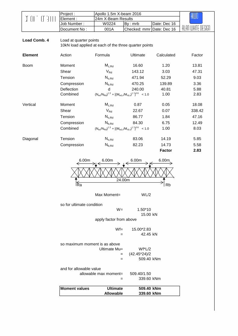
Load Comb. 4 Load at quarter points10kN load applied at each of the three quarter points
Element Action Formula Ultimate Calculated Factor
Boom Moment Mc,Rd 16.60 1.20 13.81
Shear VRd 143.12 3.03 47.31
Tension No,Rd 471.94 52.29 9.03
Compression Nb,Rd 470.25 139.89 3.36Deflection d 240.00 40.81 5.88Combined (Ned/NRd)
1.3 + [(Med,x/Mrd,x)
1.7]0.6 < 1.0 1.00 2.83
Vertical Moment Mc,Rd 0.87 0.05 18.08
Shear VRd 22.67 0.07 338.42
Tension No,Rd 86.77 1.84 47.16
Compression Nb,Rd 84.30 6.75 12.49Combined (Ned/NRd)
1.3 + [(Med,x/Mrd,x)
1.7]0.6 < 1.0 1.00 8.03
Diagonal Tension No,Rd 83.06 14.19 5.85
Compression Nb,Rd 82.23 14.73 5.58Factor 2.83
6.00m 6.00m 6.00m 6.00m
Ra Rb
Max Moment= WL/2
so for ultimate condition W= 1.50*10
15.00 kNapply factor from above
Wf= 15.00*2.83= 42.45 kN
so maximum moment is as above Ultimate Mu= Wf*L/2
= (42.45*24)/2= 509.40 kNm
and for allowable valueallowable max moment= 509.40/1.50
= 339.60 kNm
Moment values Ultimate 509.40 kNmAllowable 339.60 kNm
24.00m
Alan white design

Project : Apollo 1.5m X-beam 2016Element : 24m X-Beam ResultsJob Number : W0224 By : mrb Date: Dec 16Document No : 001A Checked: mmr Date: Dec 16
Load Comb. 5 End Shear 10kN load applied at a 1.0m distance from the support
Element Action Formula Ultimate Calculated Factor
Boom Moment Mc,Rd 16.60 0.82 20.27
Shear VRd 143.12 2.35 60.80
Tension No,Rd 471.94 6.12 77.12
Compression Nb,Rd 470.25 22.39 21.00Deflection d 240.00 6.59 36.42Combined (Ned/NRd)
1.3 + [(Med,x/Mrd,x)
1.7]0.6 < 1.0 1.00 11.32
Vertical Moment Mc,Rd 0.87 0.02 45.67
Shear VRd 22.67 0.03 839.78
Tension No,Rd 86.77 0.32 271.15
Compression Nb,Rd 84.30 4.77 17.68Combined Axial (Ned/NRd)
1.3 + [(Med,x/Mrd,x)
1.7]0.6 < 1.0 1.00 13.58
Diagonal Tension No,Rd 83.06 7.78 10.68
Compression Nb,Rd 82.23 10.52 7.82Factor 7.82
W 1.0m
Ra Rb
Max Shear Rb= W*23/24
so for ultimate condition W= 1.50*10.0
15.00 kNapply factor from above
Wf= 15.00*7.82= 117.30 kN
so maximum shear is as above Ultimate Qu= Wf*23/24
= (117.30*23)/24= 112.41 kN
and for allowable valueallowable max shear= 112.41/1.50
= 74.94 kN
Shear values Ultimate 112.41 kNAllowable 74.94 kN
24.00m
Alan white design

Project : Apollo 1.5m X-beam 2016Element : 24m X-Beam ResultsJob Number : W0224 By : mrb Date: Dec 16Document No : 001A Checked: mmr Date: Dec 16
Loadcase Ultimate AllowableNo. Moment Moment1 UDL 561.60 374.402 Point 448.20 298.803 Third 488.40 325.604 Quarter 509.40 339.60
Loadcase Ultimate AllowableNo. Shear Shear5 End Shear 112.41 74.94
Max Allowable Moment = 298.50 kNm
Max Allowable Shear = 74.50 kN
24.0m X-BEAM
Alan white design

Project : Apollo 1.5m X-beam 2016Element : 36m X-Beam ResultsJob Number : W0224 By : mrb Date: Dec 16Document No : 001A Checked: mmr Date: Dec 16
36m X-Beam Results
Alan white design

Project : Apollo 1.5m X-beam 2016Element : 36m X-Beam ResultsJob Number : W0224 By : mrb Date: Dec 16Document No : 001A Checked: mmr Date: Dec 16
Load Comb. 1 UDL load 10kN/m applied along beam
Element Action Formula Ultimate Calculated Factor
Boom Moment Mc,Rd 16.60 12.30 1.35
Shear VRd 143.12 30.70 4.66
Tension No,Rd 471.94 558.01 0.85
Compression Nb,Rd 470.25 1,675.75 0.28Deflection d 300.00 1,034.00 0.29Combined (Ned/NRd)
1.3 + [(Med,x/Mrd,x)
1.7]0.6 < 1.0 1.00 0.24
Vertical Moment Mc,Rd 0.87 0.46 1.88
Shear VRd 22.67 0.65 35.05
Tension No,Rd 86.77 12.00 7.23
Compression Nb,Rd 84.30 69.36 1.22Combined (Ned/NRd)
1.3 + [(Med,x/Mrd,x)
1.7]0.6 < 1.0 1.00 0.80
Diagonal Tension No,Rd 83.06 136.73 0.61
Compression Nb,Rd 82.23 160.43 0.51Factor 0.24
Ra Rb
Max Moment= WL2/8
so for ultimate condition W= 1.5*10
15.00 kNapply factor from above
Wf= 15*0.24= 3.60 kN
so maximum moment is as above Ultimate Mu= Wf*36^2/8
= (3.60*36^2)/8= 583.20 kNm
and for allowable valueallowable max moment= 583.20/1.50
= 388.80 kNm
Moment values Ultimate 583.20 kNmAllowable 388.80 kNm
36.00m
Alan white design
w w

Project : Apollo 1.5m X-beam 2016Element : 36m X-Beam ResultsJob Number : W0224 By : mrb Date: Dec 16Document No : 001A Checked: mmr Date: Dec 16
Load Comb. 2 Point load 10kN load applied at midspan of beam
Element Action Formula Ultimate Calculated Factor
Boom Moment Mc,Rd 16.60 0.89 18.65
Shear VRd 143.12 1.90 75.33
Tension No,Rd 471.94 58.91 8.01
Compression Nb,Rd 470.25 129.00 3.65Deflection d 300.00 72.70 4.13Combined (Ned/NRd)
1.3 + [(Med,x/Mrd,x)
1.7]0.6 < 1.0 1.00 3.18
Vertical Moment Mc,Rd 0.87 0.02 36.15
Shear VRd 22.67 0.03 666.89
Tension No,Rd 86.77 1.03 84.24
Compression Nb,Rd 84.30 3.36 25.06Combined (Ned/NRd)
1.3 + [(Med,x/Mrd,x)
1.7]0.6 < 1.0 1.00 16.09
Diagonal Tension No,Rd 83.06 7.18 11.57
Compression Nb,Rd 82.23 8.20 10.02Factor 3.18
W 18.0m
Ra RbMax Moment= WL/4
so for ultimate condition W= 1.50*10
= 15.00 kNapply factor from above
Wf= 15*3.18= 47.70 kN
so maximum moment is as above Ultimate Mu= Wf*36/4
= 47.70*36/4= 429.30 kNm
and for allowable valueallowable max moment= 429.30/1.50
= 286.20 kNm
Moment values Ultimate 429.30 kNmAllowable 286.20 kNm
36.00m
Alan white design

Project : Apollo 1.5m X-beam 2016Element : 36m X-Beam ResultsJob Number : W0224 By : mrb Date: Dec 16Document No : 001A Checked: mmr Date: Dec 16
Load Comb. 3 PL at third points 10kN load applied at each of the two third points
Element Action Formula Ultimate Calculated Factor
Boom Moment Mc,Rd 16.60 0.99 16.82
Shear VRd 143.12 2.44 58.59
Tension No,Rd 471.94 53.20 8.87
Compression Nb,Rd 470.25 161.58 2.91Deflection d 300.00 102.48 2.93Combined (Ned/NRd)
1.3 + [(Med,x/Mrd,x)
1.7]0.6 < 1.0 1.00 2.57
Vertical Moment Mc,Rd 0.87 0.04 22.83
Shear VRd 22.67 0.05 427.81
Tension No,Rd 86.77 1.35 64.27
Compression Nb,Rd 84.30 5.19 16.23Combined (Ned/NRd)
1.3 + [(Med,x/Mrd,x)
1.7]0.6 < 1.0 1.00 10.32
Diagonal Tension No,Rd 83.06 11.23 7.40
Compression Nb,Rd 82.23 12.70 6.48Factor 2.57
12.00m W W 12.00m
Ra Rb
Max Moment= WL/3
so for ultimate condition W= 1.50*10
15.00 kNapply factor from above
Wf= 15.00*2.57= 38.55 kN
so maximum moment is as above Ultimate Mu= Wf*L/3
= (38.55*36)/3= 462.60 kNm
and for allowable valueallowable max moment= 462.60/1.50
= 308.40 kNm
Moment values Ultimate 462.60 kNmAllowable 308.40 kNm
36.00m
Alan white design

Project : Apollo 1.5m X-beam 2016Element : 36m X-Beam ResultsJob Number : W0224 By : mrb Date: Dec 16Document No : 001A Checked: mmr Date: Dec 16
Load Comb. 4 Load at quarter points10kN load applied at each of the three quarter points
Element Action Formula Ultimate Calculated Factor
Boom Moment Mc,Rd 16.60 1.33 12.46
Shear VRd 143.12 3.29 43.46
Tension No,Rd 471.94 83.64 5.64
Compression Nb,Rd 470.25 226.00 2.08Deflection d 300.00 136.47 2.20Combined (Ned/NRd)
1.3 + [(Med,x/Mrd,x)
1.7]0.6 < 1.0 1.00 1.85
Vertical Moment Mc,Rd 0.87 0.05 16.69
Shear VRd 22.67 0.07 314.92
Tension No,Rd 86.77 1.65 52.59
Compression Nb,Rd 84.30 7.03 12.00Combined (Ned/NRd)
1.3 + [(Med,x/Mrd,x)
1.7]0.6 < 1.0 1.00 7.60
Diagonal Tension No,Rd 83.06 15.25 5.44
Compression Nb,Rd 82.23 17.19 4.78Factor 1.85
9.00m W 9.00m W 9.00m W 9.00m
Ra Rb
Max Moment= WL/2
so for ultimate condition W= 1.50*10
15.00 kNapply factor from above
Wf= 15.00*1.85= 27.75 kN
so maximum moment is as above Ultimate Mu= Wf*L/2
= (27.75*36)/2= 499.50 kNm
and for allowable valueallowable max moment= 499.50/1.50
= 333.00 kNm
Moment values Ultimate 499.50 kNmAllowable 333.00 kNm
36.00m
Alan white design

Project : Apollo 1.5m X-beam 2016Element : 36m X-Beam ResultsJob Number : W0224 By : mrb Date: Dec 16Document No : 001A Checked: mmr Date: Dec 16
Load Comb. 5 End Shear 10kN load applied at a 1.0m distance from the support
Element Action Formula Ultimate Calculated Factor
Boom Moment Mc,Rd 16.60 0.93 17.87
Shear VRd 143.12 2.62 54.61
Tension No,Rd 471.94 13.16 35.86
Compression Nb,Rd 470.25 44.06 10.67Deflection d 300.00 27.19 11.03Combined (Ned/NRd)
1.3 + [(Med,x/Mrd,x)
1.7]0.6 < 1.0 1.00 7.23
Vertical Moment Mc,Rd 0.87 0.02 36.15
Shear VRd 22.67 0.03 687.09
Tension No,Rd 86.77 0.46 188.63
Compression Nb,Rd 84.30 5.23 16.12Combined Axial (Ned/NRd)
1.3 + [(Med,x/Mrd,x)
1.7]0.6 < 1.0 1.00 11.94
Diagonal Tension No,Rd 83.06 9.03 9.20
Compression Nb,Rd 82.23 11.94 6.89Factor 6.89
W 1.0m
Ra Rb
Max Shear Rb= W*29/30
so for ultimate condition W= 1.50*10.0
15.00 kNapply factor from above
Wf= 15.00*6.89= 103.35 kN
so maximum shear is as above Ultimate Qu= Wf*35/36
= (103.35*35)/36= 100.48 kN
and for allowable valueallowable max shear= 100.48/1.50
= 66.99 kN
Shear values Ultimate 100.48 kNAllowable 66.99 kN
36.00m
Alan white design

Project : Apollo 1.5m X-beam 2016Element : 36m X-Beam ResultsJob Number : W0224 By : mrb Date: Dec 16Document No : 001A Checked: mmr Date: Dec 16
Loadcase Ultimate AllowableNo. Moment Moment1 UDL 583.20 388.802 Point 429.30 286.203 Third 462.60 308.404 Quarter 499.50 333.00
Loadcase Ultimate AllowableNo. Shear Shear5 End Shear 100.48 66.99
Max Allowable Moment = 286.00 kNm
Max Allowable Shear = 70.00 kN
36.0m X-BEAM
Alan white design

Project : Apollo 1.5m X-beam 2016Element : Overall X-Beam ResultsJob Number : W0224 By : mrb Date: Dec 16Document No : 001A Checked: mmr Date: Dec 16
Overall X-Beam Results
Alan white design

Project : Apollo 1.5m X-beam 2016Element : X-Beam ResultsJob Number : W0224 By : mrb Date: Dec 16Document No : 001A Checked :mmr Date: Dec 16
Load case 1 : UDL
Loadcase 1Length (m)
12182436
Average kNmMinimum kNm
Load case 2 : Central Point Load
Loadcase 2Length (m)
12182436
Average kNmMinimum kNm
Load case 3 : Two Point Loads at Third Points
Loadcase 3Length (m)
12182436
Average kNmMinimum kNm
1.5m X-BEAM
1.5m X-BEAM
1.5m X-BEAM
431.10
Ultimate
483.90476.40
448.20
491.40
561.60
429.30
488.40
450.23
534.94
440.66
431.10Moment
UltimateMoment
448.20
Ultimate
476.40
462.60
448.20546.75
583.20
Moment
Alan white design
Page 2of 5

Project : Apollo 1.5m X-beam 2016Element : X-Beam ResultsJob Number : W0224 By : mrb Date: Dec 16Document No : 001A Checked :mmr Date: Dec 16 Alan white design
Load case 4 : Three Point Loads at Quarter Points
Loadcase 4Length (m)
12182436
Average kNmMinimum kNm
Load case 5 : Shear
Loadcase 5Length (m)
12182436
Average kNMinimum kN
509.40499.50
112.41100.48
119.43
119.43
1.5m X-BEAM
1.5m X-BEAMUltimate
Shear
132.73
146.03
529.20
521.55513.90
513.90MomentUltimate
Page 3of 5

Overall Graded Results for Allowable Working Loads on a 1.5m X-Beam
For simply supported Apollo1.5m X-BEAM with a compression chord restraint at 1.0m intervals
Test Results
12 18 24 36287.4 300.0 298.5 286.097.0 79.5 74.5 67.0
Allowable loads for load distributions from resultsType of Load
12 18 24 36Uniformly Distributed load 16.0 7.4 4.1 1.8Total UDL 191.6 133.3 99.5 63.6Single point load (mid Point) 95.8 66.7 49.8 31.8Two point loads (third points) 71.9 50.0 37.3 23.8Three point loads ( quarter points) 47.9 33.3 24.9 15.9
Extrapolated Allowable loads for load distributions
Type of Load11 12 13 14 15 16 17 18 19 20 21 22 23 24 25 26 27
Uniformly Distributed load kN/m 17.6 16.0 13.6 11.7 10.2 9.0 8.0 7.4 6.6 6.0 5.4 4.9 4.5 4.1 3.7 3.4 3.1Total UDL kN 194.0 191.6 176.9 164.2 153.3 143.8 135.3 133.3 125.7 119.4 113.7 108.5 103.8 99.5 91.5 88.0 84.7Single point load (mid Point) kN 104.5 95.8 88.5 82.1 76.7 71.9 67.6 66.7 62.8 59.7 56.9 54.3 51.9 49.8 45.8 44.0 42.4Two point loads (third points) Each kN 78.4 71.9 66.3 61.6 57.5 53.9 50.7 50.0 47.1 44.8 42.6 40.7 38.9 37.3 34.3 33 31.8Three point loads ( quarter points) Each kN 52.3 47.9 44.2 41.1 38.3 35.9 33.8 33.3 31.4 29.9 28.4 27.1 26.0 24.9 22.9 22 21.2Type of Load
28 29 30 31 32 33 34 35 36Uniformly Distributed load kN/m 2.9 2.7 2.5 2.4 2.2 2.1 2.0 1.9 2Total UDL kN 81.7 78.9 76.3 73.8 71.5 69.3 67.3 65.4 64Single point load (mid Point) kN 40.9 39.4 38.1 36.9 35.8 34.7 33.6 32.7 32Two point loads (third points) Each kN 30.6 29.6 28.6 37.7 26.8 26.0 25.2 24.5 24Three point loads ( quarter points) Each kN 20.4 19.7 19.1 18.5 17.9 17.3 16.8 16.3 16
Each kN
Clear span (m)
kNkN
Clear span (m)
Clear span (m)
Allowable MomentAllowable Shear (Load on Vertical)
kN/m
Each kN
Span (m)
Alan white design

Notes: 1. This table is provided as a guide only and assume all loads are applied at nodes. All scaffolds and structures shouldbe checked by a qualified structural engineer.
2. Maximum capacity of a point load mid way between nodes is 15kN but overall buckling of the top chord should bechecked if loads are placed other than at restrained nodes. Compression chord restraint required at 1.0m c/c
3. Factor of Safety = 1.65 ( = 1.5*1.1 (material factor))4. Calculations as per BS EN 1999-1-15. For design purposes the allowable bending moment is 282.50kNm and the allowable shear is 66.50kN.
Graph Summary of Allowable Working Loads for a 1.5m X-Beam to BS EN 1999-1-1
0.0
50.0
100.0
150.0
200.0
250.0
10 15 20 25 30 35
Load
ing
(kN
)
Length of X-Beam
1.5m X-Beam Loading Capacity to BS EN 1999-1-1 (1.0m Restraint)
Total UDL
Single point load (mid Point)
Two point loads (thirdpoints)
Three point loads ( quarterpoints)
Alan white design