VWR Collection ULT Upright Freezers
68
VWR ® Collection ULT Upright Freezers Version: 1 Issued: January 12, 2015 INSTRUCTION MANUAL VWR Number Model Number Manufacturing Number Size (cu ft) Volume (L) Box Voltage Temperature -86°C FREEZERS 10160-724 VWR24086A 5603 13 368 240 120V/60Hz -86°C 10160-726 VWR24086D 5602 13 368 240 208-230V/60Hz -86°C VWR24086V 5601 13 368 240 230/50Hz -86°C 10160-728 VWR32086A 5604 17 490 320 120V/60Hz -86°C 10160-730 VWR32086D 5605 17 490 320 208-230V/60Hz -86°C VWR32086V 5635 17 490 320 230/50Hz -86°C 10160-732 VWR40086A 5656 23 651 400 120V/60Hz -86°C 10160-734 VWR40086D 5606 23 651 400 208-230V/60Hz -86°C VWR40086V 5636 23 651 400 230V/50Hz -86°C VWR40086SSD 5616 23 651 400 208-230V/60Hz -86°C 10160-736 VWR60086D 5607 28 793 600 208-230V/60Hz -86°C VWR60086V 5650 28 793 600 230/50Hz -86°C -40°C FREEZERS 10160-748 VWR24040A 5722 13 368 240 120V/60Hz -40°C 10160-750 VWR24040D 5727 13 368 240 208-220V/60Hz -40°C VWR24040V 5713 13 368 240 230V/50Hz -40°C 10160-752 VWR32040A 5728 17 490 320 120V/60Hz -40°C 10160-754 VWR32040D 5729 17 490 320 208-220V/60Hz -40°C VWR32040V 5726 17 490 320 230V/50Hz -40°C
Transcript of VWR Collection ULT Upright Freezers

VWR® Collection ULT Upright Freezers
Version: 1Issued: January 12, 2015
INSTRUCTION MANUAL
VWR Number Model NumberManufacturing
Number Size (cu ft) Volume (L) Box Voltage Temperature-86°C FREEZERS
10160-724 VWR24086A 5603 13 368 240 120V/60Hz -86°C
10160-726 VWR24086D 5602 13 368 240 208-230V/60Hz -86°C
VWR24086V 5601 13 368 240 230/50Hz -86°C
10160-728 VWR32086A 5604 17 490 320 120V/60Hz -86°C
10160-730 VWR32086D 5605 17 490 320 208-230V/60Hz -86°C
VWR32086V 5635 17 490 320 230/50Hz -86°C
10160-732 VWR40086A 5656 23 651 400 120V/60Hz -86°C
10160-734 VWR40086D 5606 23 651 400 208-230V/60Hz -86°C
VWR40086V 5636 23 651 400 230V/50Hz -86°C
VWR40086SSD 5616 23 651 400 208-230V/60Hz -86°C
10160-736 VWR60086D 5607 28 793 600 208-230V/60Hz -86°C
VWR60086V 5650 28 793 600 230/50Hz -86°C
-40°C FREEZERS10160-748 VWR24040A 5722 13 368 240 120V/60Hz -40°C
10160-750 VWR24040D 5727 13 368 240 208-220V/60Hz -40°C
VWR24040V 5713 13 368 240 230V/50Hz -40°C
10160-752 VWR32040A 5728 17 490 320 120V/60Hz -40°C
10160-754 VWR32040D 5729 17 490 320 208-220V/60Hz -40°C
VWR32040V 5726 17 490 320 230V/50Hz -40°C

VWR International
MANUAL NUMBER 7085602
1 31653 1/12/15 Release 11 - color chg, manual format, added models ccs
VERSION ECR/ECN DATE DESCRIPTION By
Preface
VWR Collection i
Important installer and user information:A redundant temperature sensing device has been included in this ULT freez-er. This device is a type “T” thermocouple. For convenient access, the thermo-couple (Figure 2-3) terminates in an interconnect jack (Figure 2-5) behind thebase front cover. (May be located differently in chests. See Section 2.) It isstrongly recommended that this thermocouple be attached to a redundant 24hour 7 day monitoring system with alarm capabilities. Connecting the sensorto a monitoring and alarm system separate from the freezer provides theutmost in product safety, should the integral system fail.
United States Europe
VWR International, LLC VWR International bvba
100 Matsonford Rd Researchpark Haasrode 2020
Radnor, PA 19087 Geldenaaksebaan 464
800-932-5000 B-3001 Leuven
http://www.vwr.com + 32 16 385011
http://be.vwr.com
Country of origin: United States
Part Number Description Quantity
122005 Key 2
380520 Neoprene Cap 2
510016 1/4-20 x 5-1/2” Bolt 2
195763 Retaining Clip 1
370563 Remote Alarm Connector 1
Packing List

VWR Internationalii VWR Collection
Preface
Contains Parts and Assemblies
Susceptible to Damage by
Electrostatic Discharge (ESD)
CAUTION
Important Read this instruction manual. Failure to read, understand and follow the instructions in this manualmay result in damage to the unit, injury to operating personnel, and poor equipment performance. s
Caution All internal adjustments and maintenance must be performed by qualified service personnel. s
Material in this manual is for information purposes only. The contents and the product it describes are subjectto change without notice. VWR International makes no representations or warranties with respect to thismanual. In no event shall VWR be held liable for any damages, direct or incidental, arising out of or related tothe use of this manual.
Intended Use: The VWR Collection freezers (see cover page for specific model series) described in this manualare high performance units for professional use. These products are intended for use as cold storage in researchuse and as a general purpose laboratory freezer, storing samples or inventory at operating temperatures between-50°C and -80°C, or -10°C and -50°C, depending on model.
It is not considered a medical device ands has therefore not been registered with a medical device regulatorybody (e.g. FDA); that is, it has not evaluated for the storage of samples for diagnostic use or for samples to bere-introduced to the body.
This unit is not intended for use in classified hazardous locations, not to be used for the storage offlammable inventory.
©2015 VWR® International. All rights reserved.
VWR International VWR Collection iii
Preface
Important operating and/or maintenance instructions. Read the accompanying text carefully.
Potential electrical hazards. Only qualified persons should perform procedures associated with thissymbol.
Equipment being maintained or serviced must be turned off and locked off to prevent possible injury.
Extreme temperature hazards, hot or cold. Use special handling equipment or wear special, protectiveclothing.
This equipment is marked with the crossed out wheeled bin symbol to indicate that this equipmentmust not be disposed of with unsorted waste.
Instead it's your responsibility to correctly dispose of your equipment at lifecycle -end by handling itover to an authorized facility for separate collection and recycling. It's also your responsibility todecontaminate the equipment in case of biological, chemical and/or radiological contamination, so asto protect from health hazards the persons involved in the disposal and recycling of the equipment.
For more information about where you can drop off your waste of equipment, please contact yourlocal dealer from whom you originally purchased this equipment.
By doing so, you will help to conserve natural and environmental resources and you will ensure thatyour equipment is recycled in a manner that protects human health.
4 Always use the proper protective equipment (clothing, gloves, goggles, etc.)
4 Always dissipate extreme cold or heat and wear protective clothing.
4 Always follow good hygiene practices.
4 Each individual is responsible for his or her own safety.

VWR Internationaliv VWR Collection
Preface
Do You Need Information or Assistance on VWR Scientific Products?
The VWR can provide information on pricing and give you quotations. We can take your order and provide delivery information on major equipment items or make arrangements to have your local sales representative contact your. Our products are listed on the internet and we can be contacted through our Internet home page.
1-800-932-5000 VWR, Toll Free, UShttp://www.vwr.com Internet Worldwide Web Home page
The VWR can supply technical information about proper setup, operation or troubleshooting of your equipment. We can fill your needs for replacement parts or
provide you with on-site service. We can also provide you with a quotation on our Extended Maintenance Program for your products.
Whatever VWR or Thermo products you need or use, we will be happy to discuss your applications. If you are experiencing technical problems, working together, we will help you locate the problem and, chances are, correct it yourself...over the telephone without a service call.
When more extensive service is necessary, we will assist you with direct factory trained technicians or a qualified service organization for on-the-spot repair. If your service need is covered by the VWR Scientific warranty, we will arrange for the unit to be repaired at our expense and to your satisfaction.
Regardless of your needs, VWR support by Thermo's professional telephone technicians is available to assist you Monday through Friday from 8:00a.m. to 6:30 p.m. Eastern Time. Please call or fax us at:
International customers, please contact your local distributor.
Sales Group
Product Service Group at Thermo
1-740-373-4763 Direct1-800-438-4851 Technical Services, Toll Free, U.S. and Canada1-740-373-4189 FAXHttp://www.vwr.com Internet Worldwide Web Home Page
Technical Services E-Mail [email protected]

VWR Collection vVWR International
Table of Contents
Product Specifications . . . . . . . . . . . . . . . . . . . . . . . . . . . . . . . . . . . . . . . .1-1
Overview . . . . . . . . . . . . . . . . . . . . . . . . . . . . . . . . . . . . . . . . . . . . . . . . . . . .2-1Control Panel Keys, Displays & Indicators . . . . . . . . . . . . . . . . . . . .2-3Keypad Operation . . . . . . . . . . . . . . . . . . . . . . . . . . . . . . . . . . . . . . .2-4Install the Freezer . . . . . . . . . . . . . . . . . . . . . . . . . . . . . . . . . . . . . . . .2-5
Choose the Location . . . . . . . . . . . . . . . . . . . . . . . . . . . . . . . . . . . .2-5Displays . . . . . . . . . . . . . . . . . . . . . . . . . . . . . . . . . . . . . . . . . . . . . . .2-5
Install the Shelves . . . . . . . . . . . . . . . . . . . . . . . . . . . . . . . . . . . . . .2-6RS-232 Communications . . . . . . . . . . . . . . . . . . . . . . . . . . . . . . . .2-6Install the Wall Bumpers . . . . . . . . . . . . . . . . . . . . . . . . . . . . . . . . .2-6Remote Alarm Contacts and Analog Output . . . . . . . . . . . . . . . . .2-7Attach the Power Cord . . . . . . . . . . . . . . . . . . . . . . . . . . . . . . . . . .2-8Connect Unit to Electrical Power . . . . . . . . . . . . . . . . . . . . . . . . . .2-8
Freezer Start-Up . . . . . . . . . . . . . . . . . . . . . . . . . . . . . . . . . . . . . . . . .2-9Set the Operating Temperature . . . . . . . . . . . . . . . . . . . . . . . . . . .2-10Set the High Temperature Alarm . . . . . . . . . . . . . . . . . . . . . . . . .2-10Set the Low Temperature Alarm . . . . . . . . . . . . . . . . . . . . . . . . . .2-11Access Code . . . . . . . . . . . . . . . . . . . . . . . . . . . . . . . . . . . . . . . . .2-11
Run Mode . . . . . . . . . . . . . . . . . . . . . . . . . . . . . . . . . . . . . . . . . . . .2-11
Calibrate . . . . . . . . . . . . . . . . . . . . . . . . . . . . . . . . . . . . . . . . . . . . . . . . . . . .3-1Calibrate the Control Probe . . . . . . . . . . . . . . . . . . . . . . . . . . . . . . . .3-1Calibrate the Optional Sample Probe . . . . . . . . . . . . . . . . . . . . . . . . .3-2
Temperature Stabilization Periods . . . . . . . . . . . . . . . . . . . . . . . . . .3-2
Configuration . . . . . . . . . . . . . . . . . . . . . . . . . . . . . . . . . . . . . . . . . . . . . . . .4-1High Alarm Test . . . . . . . . . . . . . . . . . . . . . . . . . . . . . . . . . . . . . . . .4-1Low Alarm Test . . . . . . . . . . . . . . . . . . . . . . . . . . . . . . . . . . . . . . . . .4-1System Battery Test . . . . . . . . . . . . . . . . . . . . . . . . . . . . . . . . . . . . . .4-2BUS Battery Test . . . . . . . . . . . . . . . . . . . . . . . . . . . . . . . . . . . . . . . .4-2Display Temperature . . . . . . . . . . . . . . . . . . . . . . . . . . . . . . . . . . . . .4-2Clear High Stage Alarm . . . . . . . . . . . . . . . . . . . . . . . . . . . . . . . . . . .4-3Set Access Code . . . . . . . . . . . . . . . . . . . . . . . . . . . . . . . . . . . . . . . . .4-3RS485 Address . . . . . . . . . . . . . . . . . . . . . . . . . . . . . . . . . . . . . . . . . .4-4Back-Up System Type . . . . . . . . . . . . . . . . . . . . . . . . . . . . . . . . . . . .4-4Cold Excursion . . . . . . . . . . . . . . . . . . . . . . . . . . . . . . . . . . . . . . . . .4-4Warm Excursion . . . . . . . . . . . . . . . . . . . . . . . . . . . . . . . . . . . . . . . .4-4Reset Excursion . . . . . . . . . . . . . . . . . . . . . . . . . . . . . . . . . . . . . . . . .4-4
Section 1
Section 2
Section 4
Section 3

vi VWR Collection VWR International
Alarms . . . . . . . . . . . . . . . . . . . . . . . . . . . . . . . . . . . . . . . . . . . . . . . . . . . . . .5-1Lost Communication Alarm . . . . . . . . . . . . . . . . . . . . . . . . . . . . . . .5-2Micro Board Failure Alarm . . . . . . . . . . . . . . . . . . . . . . . . . . . . . . . .5-2Multiple Alarms . . . . . . . . . . . . . . . . . . . . . . . . . . . . . . . . . . . . . . . . .5-2High Stage System Failure . . . . . . . . . . . . . . . . . . . . . . . . . . . . . . . . .5-2Error Messages . . . . . . . . . . . . . . . . . . . . . . . . . . . . . . . . . . . . . . . . . .5-3
Maintenance . . . . . . . . . . . . . . . . . . . . . . . . . . . . . . . . . . . . . . . . . . . . . . . .6-1Clean Air Filter . . . . . . . . . . . . . . . . . . . . . . . . . . . . . . . . . . . . . . . . .6-1Clean the Condenser . . . . . . . . . . . . . . . . . . . . . . . . . . . . . . . . . . . . .6-1Clean the Water-cooled Condenser . . . . . . . . . . . . . . . . . . . . . . . . . .6-2
Clean in Place (CIP) . . . . . . . . . . . . . . . . . . . . . . . . . . . . . . . . . . . .6-2Prepare the Unit for Storage . . . . . . . . . . . . . . . . . . . . . . . . . . . . . . .6-2
Long Term Storage with Water-cooled Condenser . . . . . . . . . . . . .6-3Defrost the Chamber . . . . . . . . . . . . . . . . . . . . . . . . . . . . . . . . . . . . .6-3Clean the Door Gasket . . . . . . . . . . . . . . . . . . . . . . . . . . . . . . . . . . .6-4Vacuum Relief Port . . . . . . . . . . . . . . . . . . . . . . . . . . . . . . . . . . . . . .6-4
Vacuum Relief Port Maintenance . . . . . . . . . . . . . . . . . . . . . . . . . .6-5Replace the Battery . . . . . . . . . . . . . . . . . . . . . . . . . . . . . . . . . . . . . .6-6
Factory Installed Options . . . . . . . . . . . . . . . . . . . . . . . . . . . . . . . . . . . . . .7-1Back-Up System (BUS) . . . . . . . . . . . . . . . . . . . . . . . . . . . . . . . . . . .7-1
Install Vent Stack, Solenoid & Injection Asm. . . . . . . . . . . . . . . . .7-2Install the Temperature Probe . . . . . . . . . . . . . . . . . . . . . . . . . . . . .7-3Connect the Probe/Solenoid Harness . . . . . . . . . . . . . . . . . . . . . . .7-4BUS Operation and Maintenance . . . . . . . . . . . . . . . . . . . . . . . . . .7-5
Chart Recorder . . . . . . . . . . . . . . . . . . . . . . . . . . . . . . . . . . . . . . . . .7-7Change the Recorder Temperature Range . . . . . . . . . . . . . . . . . . . .7-8Calibrate the Recorder . . . . . . . . . . . . . . . . . . . . . . . . . . . . . . . . . .7-9
Water-cooled Condenser . . . . . . . . . . . . . . . . . . . . . . . . . . . . . . . . .7-10Water Connections . . . . . . . . . . . . . . . . . . . . . . . . . . . . . . . . . . . .7-12
Warranty Information . . . . . . . . . . . . . . . . . . . . . . . . . . . . . . . . . . . . . . . . .8-1
Handling Liquid Nitrogen . . . . . . . . . . . . . . . . . . . . . . . . . . . . . . . . . . . . .A-1Introduction . . . . . . . . . . . . . . . . . . . . . . . . . . . . . . . . . . . . . . . . . . .A-2Handling Liquid Carbon Dioxide . . . . . . . . . . . . . . . . . . . . . . . . . . .A-4First Aid . . . . . . . . . . . . . . . . . . . . . . . . . . . . . . . . . . . . . . . . . . . . . .A-4
Table of Contents
Section 5
Section 6
Section 7
Section 8
Appendix

Section 1 Product Specifications
VWR Collection 1-1VWR International
Temperature Range -50°C (-58°F) to -86°C (-123°F) or -10°C (-14°F) to -40°C (-40°F) in an 18°C to 28°C (64.4°F to 82.4°F) ambient
Capacity
13.0 cu. ft. (368.1 liters)
17.3 cu. ft. (489.9 liters)
23.0 cu. ft. (651.3 liters)
28.0 cu. ft. (792.8 liter
Refrigeration 2545 BTUH (Two compressors for -86C units), (One compressor for -40C units)
Insulation CFC-free, foamed-in-place urethane: minimum 5.0" (12.7cm) cabinet; 4.5” (11.4 cm) door
Electrical - nominal voltage ±10% 208-230VAC, 60 Hz, 12 FLA 230VAC, 50 Hz, 12 FLA 120VAC, 60 Hz, 16 FLA
Breaker Requirements15 Amp, Dedicated Circuit, 15 Amp Time Delay Breaker
15 Amp, Dedicated Circuit, 15 Amp Time Delay Breaker
20 Amp, Dedicated Circuit,20 Amp Time Delay Breaker

1-2 VWR Collection VWR International
Section 1Specifications
CertificationsDeclaration of Conformity is available from the factory
Safety SpecificationsIndoor Use OnlyAltitude - Up to 2,000 metersTemperature - 5°C to 43°CHumidity - Maximum RH 80% for temperatures up to 31°C, decreas-ing linearly to 50% RH at 40°CMains Supply Fluctuations - Mains supply voltage fluctuations not toexceed ±10% of the nominal voltageInstallation Category II 1
Pollution Degree 2 2
Class of Equipment I
1 Installation category (overvoltage category) defines the level of transient overvoltage which theinstrument is designed to withstand safely. It depends on the nature of the electricity supply and itsovervoltage protection means. For example, in CAT II which is the category used for instruments ininstallations supplied from a supply comparable to public mains such as hospital and researchlaboratories and most industrial laboratories, the expected transient overvoltage is 2500V for a230V supply and 1500V for a 120V supply.
2 Pollution degree describes the amount of conductive pollution present in the operatingenvironment. Pollution degree 2 assumes that normally only non-conductive pollution such as dustoccurs with the exception of occasional conductivity caused by condensation.

VWR Collection 2-1VWR International
Section 2 Overview
Control PanelOptional
Back-Up System Controls
Optional Temp Recorder
Optional Back-up
System Connections
RS-232 or RS-485
Interface
Power Switch
(mains disconnect)Power Inlet
Wall Bumper
(pre-tapped holes)
Remote Alarm Contacts
and Analog Output
Shelf
Bracket
Sealant
(Caution: This is a critical seal.
Seal must be maintained.)
Optional - Recorder Probe/Datalogger Probe
Control RTD/Redundant Type T
Thermocouple Probe
Optional Miscellaneous Accessories Probe
Figure 2-1. Front View
Figure 2-2. Rear View
Figure 2-3. Chamber Probes
Figure 2-1
• Control Panel - keypad,displays and indicators
• BUS (Optional Back UpSystem) panel
• Optional temperaturerecorder (7 day, one pen)
Figure 2-2
• Remote alarm contactsand selectable analogoutput connection (0-1V,4-20mA (default), 0-5V)
• Power inlet for powercord connection.
• Optional BUSconnections for probe andsolenoid
• RS-232 (default) or RS-485 interface
• Power switch (mainsdisconnect)
Figure 2-3
• Vacuum relief port -pressure equalization port
• Probe cover

2-2 VWR Collection VWR International
Section 2Overview
Figure 2-4
• Probe cover houses control, optional recorder, redundant alarm probes.
Figure 2-5
• Battery mounting bracket(s)
• Battery power switch (freezer and BUS)
• Freezer battery
• Optional BUS battery
• Freezer filter location
• Mode Select Switch - Used to select Run, Settings, Calibrate and
Figure 2-4. Vacuum Relief and Probe Cover Location
O
Battery power
switchTo
remove filterThermocouple
interconnect jack
Battery mounting
bracket
Freezer batteryand optional BUS battery
Figure 2-5. Battery(s) Location and Switch
Chamber ProbeCover
Vacuum ReliefPort

VWR Collection 2-3VWR International
Section 2Overview
System Configuration Modes.
Mode Select Indicators -
Run: Run Menu
Settings: Set Points Menu
Calibrate: Calibrate Menu
Configuration: Configuration Menu
• Temperature Display - Displays temperature in degrees Celsius.
• Alarm Indicator - Light pulses on/off during an alarm condition of thecabinet.
• Mute - Silences the audible alarm.
• Low Battery - indicates a low battery condition of the freezer battery.
• Hot Condenser - indicates a hot condenser condition.
• Message Center - displays system status and alarms.
• Scroll for Parameters Arrows - moves the operator through the choicesof the selected mode.
• Up and Down Arrows - Increases or decreases values, toggles betweenchoices.
• Enter Arrow - Stores the value into memory.
Control Panel Keys,Displays & Indicators
Figure 2-6. Control Panel
MuteModeAlarmIndicator
Temperature Display
Enter ArrowUp and Down ArrowsScroll for Parameters Arrows
Low Battery
HotCondenser

The VWR Collection freezer has four basic modes which allow freezersetup: Run, Settings, Calibrate and Configuration.
Run is the default mode for the freezer during normal operation. Settings is used to enter system set points for freezer operation. Calibrate is used to calibrate various system parameters.
Configuration allows for custom setup of various options.
The chart below shows the selections under each of the modes.
Scroll for Parameters Arrows: Steps the operator through the parametersof SETTINGS, CALIBRATE and CONFIGURATION Modes. Theright arrow goes to the next parameter, the left arrow returns to theprevious parameter. Up Arrow: Increases or toggles the parameter value that has been selectedin the SETTINGS, CALIBRATE, and CONFIGURATION Modes. Enter: Must press Enter key to save to memory any changed values.Down Arrow: Decreases or toggles the parameter values that have beenselected in the SETTINGS, CALIBRATE and CONFIGURATIONModes.Mute Key: Press to silence the audible alarm. See Section 4 for alarmringback times.
2-4 VWR Collection VWR International
Section 2Overview
Keypad Operation
Run Settings Calibrate Configuration
Default ModeSystem Ok
Control Set Point Control Probe High Alarm Test
Line Voltage High Alarm Set Point Optional SampleProbe Low Alarm Test
Compensated Voltage Low Alarm Set Point System Battery Test
HSHX Temperature Optional Back UpSystem Set Point BUS Battery Test
Display Temperature
Clear High StageAlarm
Set Access Code
RS485 Address
BUS type CO2 or LN2
Cold Excursion
Warm Excursion
Reset Excursion

Message Center: Displays the system status (Mode) at all times. DisplaysSYSTEM OK during normal operation, or alarm messages if the systemdetects an alarm condition. See the Alarms section.
Caution If tipped more than 45°, allow the unit to set upright for 24 hoursbefore start up. s
To remove the freezer from the pallet, use the ½" wrench to remove all thebolts securing the shipping bracket to the pallet.
Remove the shipping bracket. Remove the ramp boards from the palletand place the slotted end over the ramp brackets on the pallet. Thesupport blocks on the ramps will be facing down. Before moving thefreezer, make sure the casters are unlocked and moving freely. Align thecaster with the ramp boards. Use adequate personnel to roll the freezer offthe pallet.
The freezer can be easily pushed to the desired approved location,described below. If necessary, the doors and lower front panel may beopened to move the unit through tight openings. When the freezer is inposition, set the front caster brakes.
Caution If the factory installed option water-cooled condenser is present,do not turn the freezer on without water connected and flowing. Damageto the refrigeration system could occur within 5 minutes if water is notconnected and flowing on unit start-up. Refer to Section 6. s
Locate the freezer on a firm, level surface in an area with an ambienttemperature between 18°C and 28°C. Provide ample room to reach themains disconnect switch (power switch) located on the rear of the freezer.
Caution The freezer must not be moved with the product load inside. s
Caution For proper ventilation and airflow, a minimum clearance of 5” atthe rear and top, and a clearance of 8” on the side of the freezer isrequired. Allow adequate space in front of the freezer for door opening. s
VWR Collection 2-5VWR International
Section 2Overview
Displays
Install the Freezer
Choose the Location

The parts bag, located inside the cabinet, contains the following parts.
Install the bolts into the pre-tapped holes on the back of the compressorsection. Install a neoprene cap on each bolt. Refer to Figure 1-2 for thelocation of the pre-tapped holes.
Install the shelf clips into the shelf pilasters (front and back) at the desiredshelf level. Install the shelves in the cabinet onto the clips.
Note On units having the optional 5 inner door option, refer to theinstructions accompanying the inner door kit. s
The VWR Collection freezer has a data communications interface. Thefactory default setting is RS-232.
The wiring identification for the interface is shown in Figure 2-7. Onenine pin, sub "D" style connector is located on the back of the freezer. SeeFigure 1-2 for the location of the connector on the freezer.
The freezer transmits temperature information every 60 minutes. Astandard DB9 serial extension cable can be used to connect the freezer to aserial device. Some serial devices may require a null modem adapter.
Data format:Baud . . . . . . . . . . . . . . . . . . . . . . . . . . . . . . . .1200Data bits . . . . . .8 (7 bit ASCII with leading zero)Start bits . . . . . . . . . . . . . . . . . . . . . . . . . . . . . . . .1Stop bits . . . . . . . . . . . . . . . . . . . . . . . . . . . . . . . .2Parity . . . . . . . . . . . . . . . . . . . . . . . . . . . . . . .none
2-6 VWR Collection VWR International
Section 2Overview
Install the Wall Bumpers
Quantity Stock # Description Purpose
2 510016 1/4-20x5-1/2” Bolt Wall Bumper
2 380520 Neoprene Cap Cap Protector
Install the Shelves
RS-232 Communications
Figure 2-7. Wiring Identification

The data transfer sequence is transmitted in the following format. X refersto numerical temperature data.(NUL) (-) XXX (SP) C (SP) (Error Message) (SP) (LF) (CR) (EOT) (SP)
In the event of a CNTRLFAIL, Er07, or the control probe is out of rangeerror, the numerical temperature data (XXX) in the transmission would bereplaced by T_ERR.
If no alarm condition exists, spaces will be sent. A total of 20 characterswill be sent.
SP - Space LF - Line feedCR - Carriage return EOT - End of text (4)NUL - Null character (00)
If an alarm condition does exist, “Error Message” in the protocol will bereplaced by the following:
UNDERTEMP (temperature above the low alarm setpoint)OVERTEMP (temperature below the high alarm setpoint)PWRFAIL (AC power failure)CNTRLFAIL (Control probe failure)Er07 (micro failure)HSHX FAIL (Heat exchanger failure)HOT COND (Hot condenser)
The VWR Collection freezer has remote alarm contacts and analogoutput. See Figure 2-2 for the location of the remote alarm contacts. Theremote alarm connector is located in the parts bag provided with themanual. It must be installed if connecting the freezer to an alarm system.After installing the wiring from the alarm system to the connector, installthe connector to the freezer microboard and secure with the two screwsprovided.
VWR Collection 2-7VWR International
Section 2Overview
RS-232 Communications(continued)
Remote Alarm Contactsand Analog Output

The remote alarm provides a NO (normally open) output, a NC (normallyclosed) output and COM (common). The contacts will trip on a poweroutage, high temperature alarm or low temperature alarm. They will alsotrip on high stage, control probe and microboard failures. Figure 2-8 showsthe remote contacts in alarm state.
The analog output function allows the freezer to output signalsrepresenting the temperature of the freezer cabinet. The factory defaultsetting is 4-20 mA. Refer to Figure 2-9 for output specifications.
Insert the power cord into thepower inlet module. Place theretaining bracket (P/N195763) over the connector.Tighten retaining screws tosecure.
Caution See the serial tag on the side of the unit for electrical specificationsor refer to the electrical schematics in this manual. s
Caution If the factory installed option water-cooled condenser is present,do not turn the freezer on without water connected and flowing. Damageto the refrigeration system could occur within 5 minutes if water is notconnected and flowing on unit start-up. Refer to Section 6. s
2-8 VWR Collection VWR International
Section 2Overview
Attach the Power Cord
Connect Unit to ElectricalPower
Figure 2-10. Power Cord Connection
Remote Alarm Contactsand Analog Output (cont.)
4-20 mA 0-1V 0-5V
Temperature -100 to +50°C -100 to +50°C -100 to +50°C
Figure 2-8. Remote Alarm Contact Pins
Figure 2-9. Specifications
IMPORTANT USER INFORMATION
CAUTION! Stored product should be protected
by a redundant 24 hour/day monitoring system
with alarm capability. An interconnect jack and
thermocouple are installed for centralized
monitoring, should on-board system fail.
The freezer should be operated on a dedicated grounded service. Checkthe voltage rating on the serial tag of the unit and compare it with theoutlet voltage. Then, with the power switch turned off, plug the line cordinto the wall outlet.
First turn on the freezer power switch. Then open the lower front door bygrasping the bottom left corner. Locate the battery switch (Figure 1-5) andturn it to Standby mode ( ). During initial freezer start-up, the systembattery may require charging and the Low Battery message may appear inmessage center.
Caution Ensure the battery switch is turned to Standby mode ( ). Therechargeable batteries require 36 hours to charge at initial start-up. A “LowBattery” alarm may occur until the batteries are fully charged. Should apower failure occur during the initial start-up period, the electronics willhave limited operation. s
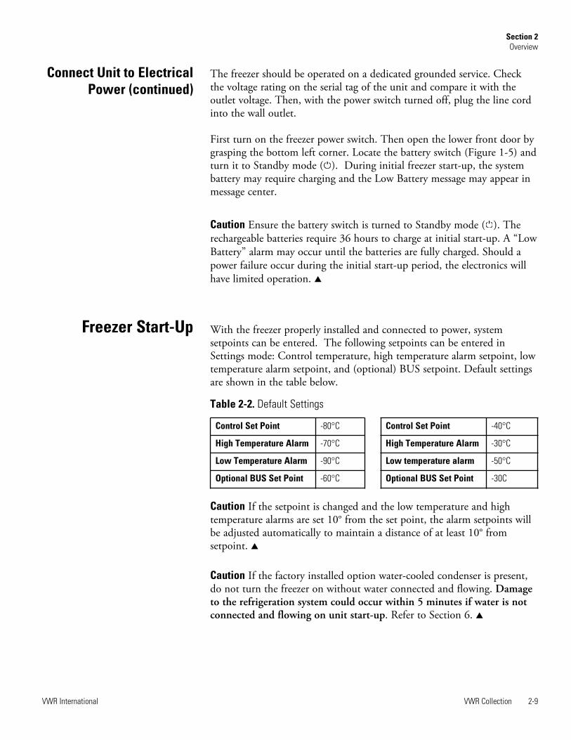
With the freezer properly installed and connected to power, systemsetpoints can be entered. The following setpoints can be entered inSettings mode: Control temperature, high temperature alarm setpoint, lowtemperature alarm setpoint, and (optional) BUS setpoint. Default settingsare shown in the table below.
Caution If the setpoint is changed and the low temperature and hightemperature alarms are set 10° from the set point, the alarm setpoints willbe adjusted automatically to maintain a distance of at least 10° fromsetpoint. s
Caution If the factory installed option water-cooled condenser is present,do not turn the freezer on without water connected and flowing. Damageto the refrigeration system could occur within 5 minutes if water is notconnected and flowing on unit start-up. Refer to Section 6. s
VWR Collection 2-9VWR International
Section 2Overview
Connect Unit to ElectricalPower (continued)
Freezer Start-Up
Control Set Point -80°C
High Temperature Alarm -70°C
Low Temperature Alarm -90°C
Optional BUS Set Point -60°C
Table 2-2. Default Settings
Control Set Point -40°C
High Temperature Alarm -30°C
Low temperature alarm -50°C
Optional BUS Set Point -30C

VWR Collection freezers have an operating temperature range of -50°C to-86°C, or -10°C to -40°C, depending on model and ambient temperature.The freezer is shipped from the factory with a temperature set point of-80°C, or -40°C, depending on model. To change the operatingtemperature setpoint:
1. Press the Mode key until the Settings indicator lights.
2. Press right arrow until “SET PT = -XX” is displayed in message center.
3. Press the up/down arrow key until the desired temperature set point isdisplayed.
4. Press Enter to save the set point.
5. Press the Mode key until the Run indicator lights for Run mode orpress the right/left arrow keys to go to next/previous parameter.
If no control keys are pressed, the freezer will automatically return to RUNmode after 5 minutes.
For -40°C units: At -20°C operation, probe may need to be calibrated toensure cabinet temperatures are within required range. Refer to Calibrationsection for procedure.
The high temperature alarm will activate an audible/visual warning whenthe freezer chamber temperature has reached or exceeded the hightemperature alarm set point. To set the high temperature alarm set point:
1. Press the Mode key until the Set indicator lights.
2. Press right arrow until “HI ALM = -XX” is displayed in messagecenter.
3. Press the up or down arrow key until the desired high temperaturealarm set point is displayed.
4. Press Enter to save the setting.
5. Press the Mode key until the Run indicator lights or press the right orleft arrow to go to the next or previous parameter.
If no control keys are pressed, the freezer will automatically return to RUNmode after 5 minutes.
Caution The high alarm set point must be set at least 5°C from thecontrol set point. At initial start-up, the high temperature alarm is disableduntil the cabinet reaches set point, or 12 hours elapse. s
2-10 VWR Collection VWR International
Section 2Overview
Set the High TemperatureAlarm
Set the OperatingTemperature

The low temperature alarm will activate an audible/visual warning whenthe freezer chamber temperature has reached or decreased below the lowtemperature alarm set point. To set the low temperature alarm set point:
1. Press the Mode key until the Settings indicator lights.
2. Press the right arrow until “LO ALM = -XX” is displayed in themessage center.
3. Press the up or down arrow key until the desired low temperaturealarm set point is displayed.
4. Press Enter to save the setting.
5. Press the Mode key until the Run indicator lights or press the right orleft arrow to go to the next or previous parameter.
If no control keys are pressed, the freezer will automatically return to RUNmode after 5 minutes.
Note The low alarm set point must be set at least 5°C from the control setpoint. s
An access code of 000 is required to access the Settings, Calibrate orConfiguration modes. If the access code is not set at the default ‘000’, acode must be entered to leave RUN mode. See Section 4 for instructionson modifying the access code.
Run is the default mode for the freezer. The run mode will display thecabinet temperature on the temperature display and ‘SYSTEM OK’ on themessage center under normal operating conditions. In addition, this modeallows display of the following information:
LINE VOLTAGE
COMPENSATED VOLTAGE
HSHX TEMPERATURE (heat exchanger temperature), - 86°C models
This information is scrolled individually by pressing the right arrow key.In each case, the message center returns to SYSTEM OK in 10 seconds ifno keys are pressed.
VWR Collection 2-11VWR International
Section 2Overview
Access Code
Set the Low TemperatureAlarm
Run Mode

2-12 VWR Collection VWR International
Section 2Overview

VWR Collection 3-1VWR International
Section 3 Calibrate
Once the freezer has stabilized, the control or sample probe may need tobe calibrated. Calibration frequency is dependent on use, ambientconditions and accuracy required. A good laboratory practice wouldrequire at least an annual calibration check. On new installations, allparameters should be checked after the stabilization period.
On -40°C models only: For -20°C operation, calibration may be needed toensure cabinet air temperatures are within a specified range.
Caution Before making any calibration or adjustments to the unit, it isimperative that all reference instruments be properly calibrated. s
Plug a type T thermocouple reader into the receptacle located inside thelower door (Figure 2-5). Compare the control temperature set point tothe temperature of the measuring device. See Chart 3-1 at the end of thissection for more detail.
1. Press the Mode key until the Calibrate indicator lights.
2. Press right arrow until “CONT T = -XX.X” appears in message center.
3. Press up/down arrow to match the display to calibrated instrument.
4. Press Enter to store calibration.
5. Press the Mode key to return to Run or the right/left arrow to go tonext/previous parameter.
On -40°C models only: Probe Calibration for -20°C Operation; Notethat if the peak variation is within ±5°C of set value, then no calibration isrequired.
1. Set temperature to -20C.
2. Calibrate probe to -4°C (-2.5 for 13 ft units) per above procedure.
3. Allow unit to stabilize to -20°C per temperature stabilizationperiod below.
4. Check peak variation after unit has achieved steady state operation.Probe may need to be calibrated a second time to achieve therequired range.
Calibrate the ControlProbe

3-2 VWR Collection VWR International
Section 3Calibrate
Calibrate the OptionalSample Probe
For freezers with the optional sample probe, place the calibratedinstrument in the center of the sample bottle. The bottle should contain anappropriate medium and the measuring instrument should be centered inthe bottle.
1. Press the Mode key until the Calibrate indicator lights.
2. Press the right arrow until “SAMP T = -XX.X” appears in the messagecenter.
3. Press up/down arrow to match display to calibrated instrument.
4. Press Enter to store calibration.
5. Press the Mode key to return to Run or the right/left arrow to go tonext/previous parameter.
See Chart 3-1 for calibration process functions.
Temperature Stabilization Periods
Startup - Allow 12 hours for the temperature in the cabinet to stabilizebefore proceeding.
Already Operating - Allow at least 2 hours after the display reaches setpoint for temperature to stabilize before proceeding.
Caution During calibration, the temperature display is not available. s
If no keys are pressed for approximately five minutes while in calibrationmode, the system will reset to Run mode.
Temperature StabilizationPeriods

VWR Collection 3-3VWR International
Section 3Calibrate

VWR Collection 4-1VWR International
Section 4 Configuration
The Configuration Mode is used for testing and custom setup of thefreezer. The configuration functions listed and described below may notbe necessary in all applications, but are available if needed. See Chart 3-1for more detail.
The high alarm test is used to verify the high alarm will activate, shouldthe freezer temperature equal or exceed the high alarm set point.
1. Press the Mode key until the Configuration indicator lights.
2. Press the right arrow until HI ALRM TEST is displayed in themessage center.
3. Press Enter to initiate the test.
The temperature on the display will begin to increase until the high alarmset point has been reached. The audible alarm will sound and the alarmindicator will flash. Press the Mute key to silence the alarm.
The low alarm test is used to verify the low alarm will activate, should thefreezer temperature equal or become less than the low alarm set point.
1. Press the Mode key until the Configuration indicator lights.
2. Press the right arrow until LO ALRM TEST is displayed in themessage center.
3. Press Enter to initiate the test.
The temperature on the display will begin to decrease until the low alarmset point has been reached. The audible alarm will sound and the alarmindicator will flash. Press the Mute key to silence the alarm.
High Alarm Test
Low Alarm Test

4-2 VWR Collection VWR International
Section 4Configuration
System Battery Test To test the charge of the freezer battery:
1. Press the Mode key until the Configuration indicator lights.
2. Press the right arrow until SYS BAT TEST is displayed in the messagecenter.
3. Press Enter to initiate the test.
TESTING BATT displays during the testing period. Upon completion ofthe test, the message center displays BATT GOOD or BATT FAIL. Whena test is failed, the audible alarm sounds, the alarm indicator and the LowBattery indicator light. Press the Mute key and the alarm indicator goesout. The Low Battery light stays on until a future battery test is performedand passed.
To test the charge of the BUS battery:
1. Press the Mode key until the Configuration indicator lights.
2. Press the right arrow until BUS BAT TEST is displayed in themessage center.
3. Press Enter to initiate the test.
TESTING BATT displays during the testing period. Upon completion ofthe test, the message center displays BBAT GOOD or BBAT FAIL. Whena test is failed, the audible alarm sounds, the alarm indicator and the LowBattery indicator lights. Press the Mute key. The audible alarm and alarmindicator go off. The Low Battery light stays on. If this test fails, it isrecommended to replace the BUS battery.
This function, only available on freezers with the optional sample probe,allows the user to select which temperature is displayed in the temperaturedisplay window. The options are CONTROL or SAMPLE.
1. Press the Mode key until the Configuration indicator lights.
2. Press the right arrow until DISP CONTROL or DISP SAMPLE isdisplayed in the message center.
3. Press up/down arrow to toggle between the two display selections.
4. Press Enter to save.
If control probe is selected, the temperature display will be oncontinuously. If sample probe is selected, the temperature display will bepreceded with a letter ‘S’.
BUS Battery Test
Display Temperature

VWR Collection 4-3VWR International
Section 4Configuration
Should a high stage alarm occurred, it may become necessary to the clearthe alarm condition after the condition has been corrected.
1. Press the Mode key until the Configuration indicator lights.
2. Press the right arrow until CLR HS ALARM is displayed in themessage center.
3. Press Enter to clear the alarm.
To set the Access Code:
1. Press the Mode key until the Configuration indicator lights.
2. Press the right arrow until “SET ACC CODE” is displayed in themessage center.
3. Press Enter.
4. The message center will display ACC CODE = 000. Press the up ordown arrow key until the desired access code is displayed (000 - 999).Press the left or right arrow key to select digit 1, 2, 3.
Note The left and right arrow keys are used to move from the firstthrough the third digits within the access code. s
5. Press Enter to save the setting
6. Press the Mode key until the Run indicator lights. A three digit AccessCode can be entered to avoid unauthorized personnel from changingthe set points, calibration, or configuration. A setting of 000 willbypass the access code. The factory setting is 000.
Clear High StageAlarm
Set Access Code

The freezer will need to have a unique identification address for datacommunications. This address is set through the Configuration mode.
1. Press the Mode key until the Configuration indicator lights.
2. Press the right arrow until RS485ADDR is displayed in the messagecenter.
3. Press Enter. The message center will display 485 ADDR XX.
4. Press up or down arrow to select the appropriate address for the freezer(1 - 24).
5. Press Enter to save.
This function, which is only available on freezers with the optional BUS(back up system), allows the user to select which type of gas is injected intothe freezer chamber. The options are CO2 and LN2.
1. Press the Mode key until the Configuration indicator lights.
2. Press the right arrow until BUS TYPE CO2 or BUS TYPE LN2 isdisplayed in the message center.
3. Press up/down arrow to toggle between the two display selections.
4. Press Enter to save.
This function displays the coldest temperature recorded by the controlprobe.
This function displays the warmest temperature recorded by the controlprobe.
This function resets the cold and warm excursions.
4-4 VWR Collection VWR International
Section 4Configuration
RS485 Address
Cold Excursion
Warm Excursion
Reset Excursion
Back-Up System Type

VWR Collection 4-5VWR International
Section 4Configuration

4-6 VWR Collection VWR International
Section 4Configuration

VWR Collection 4-7VWR International
Section 4Configuration


VWR Collection 5-1VWR International
Section 5 Alarms
The VWR Collection freezer alarm system is shown in the table below.When an alarm is active, the message appears in the LED message center.Press the Mute key to silence the audible alarm for the ringback period.The visual alarm will continue until the freezer returns to a normalcondition. The alarms are momentary alarms only. When an alarmcondition occurs and then returns to normal, the freezer automaticallyclears the alarm condition and the message center.
All alarm delays and ringback times are ±30 seconds.* The automatic battery test runs immediately on initial start-up, then every 8 hours thereafter.
Description Message Delay Ringback Relay
No alarm condition exists SYSTEM OK ---- ---- ----
Power Failure POWER FAIL 1 min. 15 min. Yes
High Temperature Alarm TEMP IS HIGH 1 min. 15 min. Yes
Low Temperature Alarm TEMP IS LOW 1 min. 15 min. Yes
Door Ajar DOOR IS OPEN 1 min. 15 min. No
Low Battery* LOW BATTERY 1 min. 12 hours No
Low BUS Battery (optional) LOW BUS BATT 1 min. 15 min. No
Control Probe Failure PROBE 1 FAIL 1 min. 15 min. Yes
Heat Exchanger Probe Failure PROBE 2 FAIL 1 min. 15 min. No
Condenser Probe PROBE 3 FAIL 1 min. 15 min. No
Sample Probe Failure (optional) PROBE 4 FAIL 1 min. 15 min. No
High Stage System Failure HS SYST FAIL 1 min. 15 min. Yes
Condenser Hot Condition (-86°C models only) HOT CONDENSR 1 min. none No
Wrong Power WRONG POWER 0 min. none Yes
Micro Board Failure MICRO FAIL 0 min. 15 min. Yes

5-2 VWR Collection VWR International
Section 5Alarms
This condition is created when the high stage compressor and fans run for30 minutes and are not capable of cooling the interstage heat exchanger tothe proper temperature. Under this condition, the high stage compressorand fans will turn off after 30 minutes, and an audible and visual alarmwill occur along with the "HS SYST FAIL" message in the LED messagecenter.
When multiple alarm conditions occur, active messages are displayed in themessage center one at a time, updating at 5 second intervals. Pressing Muteduring multiple alarms causes all active alarms to be muted and to ringback in 15 minutes.
An internal communications failure has occurred with the micro board.During this alarm, the compressor(s) attempt to run continuously.However, with this type of failure, freezer operation becomesundependable.
Communication between the micro board and the display board has beenlost. Under this condition, the visual alarm LED flashes along with dashes(----) in the temperature display. In addition, ‘LOST COMM’ flashes inthe message center. Contact Technical Services.
High Stage SystemFailure (-86°C models only)
Multiple Alarms
Micro Board FailureAlarm
Lost CommunicationAlarm

VWR Collection 5-3VWR International
Section 5Alarms
Error MessagesError High End Message Notes
Er00 “INV. MODEL”
Name: Improper model selected.Description: Indicates that DIP SW3 has not selected a proper model or can’t be accessed properly.Response: Display shows “Er00” and will not start-up until a proper model is selected. Contact TechnicalServices.
ErA1 “ NO FREQUENCY” This error condition will prevent peripherals (fans, compressors, etc.) from powering up with the incorrectvoltage.Name: Voltage/Frequency failureDescription: Indicates the measured RMS line voltage did not agree with the logic level sensed by themicros provided by the installed high voltage PCB; or the measured RMS voltage is not within a tolerablerange (<180VAC < 270 for 230VAC unit / <85 VAC < 160 for 115VAC unit); or the frequency measured over 10cycles was not within a tolerable range (55 Hz < Freq < 70 Hz for 60 Hz units / 40 Hz < Freq < 55 Hz for 50 Hzunits)Response: This condition is checked at power on reset and if it is active the unit will NOT power up. Theunit will indefinitely display “Er_1” in the display and continue to monitor the frequency and voltage.Furthermore, the audible alarm will sound. Other startup error messages may be displayed prior to this mes-sage; however, the system will stop the startup sequence for this condition.ErA1 .. No pulses (zero crossings) detected to determine frequency (50 / 60 Hz)ErC1 .. Frequency detected is below 50 HzErd1 .. Frequency detected is above 60 Hz (Possible noise spikes on supply voltage)ErE1 .. Unit is 230V and the voltage detected is below the low limit (180VRMS)ErF1 .. Unit is 230V and the voltage detected is above the high limit (260VRMS)Erg1 .. Unit is 115V and the voltage detected is below the low limit (85VRMS)ErH1 .. Unit is 115V and the voltage detected is above the high limit (160VRMS)
ErC1 “FREQ <50Hz”
Erd1 “FREQ >60Hz”
ErE1 “VAC < 180V”
ErF1 “VAC > 260V”
Erg1 “VAC < 85V”
ErH1 “VAC > 160V”

5-4 VWR Collection VWR International
Section 5Alarms
Error(cont.) High End Message Notes
Er02 “CNT PRB FLT”
Name: Control (Cabinet) Sensor FailureDescription: This condition indicates that the control sensor has failed to produce a valid reading for >12consecutive reads (~60 seconds).Response: The unit will stage both compressors on (if necessary) and the unit will attempt to head to bot-tom out. If the sensor recovers, the system will begin to operate normally and respond to the temperaturefeedback. The remote alarm contacts will become active regardless of the key position for this mode of fail-ure. ‘Er02’ will be added to the main display queue and the last valid cabinet temperature value will not bedisplayed
Er03 “HSHX PRB FLT”
Name: Heat Exchange Sensor FailureDescription: This condition indicates that the heat exchange sensor has failed to produce a valid readingfor >12 consecutive reads (~60 seconds).Response: The display will show “Er03” only when the button sequence to read the heat exchange sensoris depressed.
Er05 N/A
Name: Display Firmware Integrity FailureDescription: The display firmware has failed to pass its CRC CCITT checksum integrity test.Response: The display performs this check at startup and the display board will fail to startup with out anyerror indication if it does not pass this at power on.
Er06 N/A
Name: Micro Firmware Integrity FailureDescription: The micro firmware has failed to pass its CRC CCITT checksum integrity test.Response: This is checked at power on reset and the “Er06” will be displayed for ~10 seconds at startup ifthis condition exists.
Er07 “MICRO FAIL”
Name: Micro Fail - CS5521 SPI Failure / UISR FailureDescription: This condition indicates a micro board failure due to either the SPI bus is unable to communi-cate with the ADC device or a UISR event caused the microcontroller to be in an unstable state.Response: The unit will try to recover from this fault three times by a hardware reset of the micro board. Inthe event that the system couldn’t rectify the issue, the following sequence of events will occur:
1. Remote alarm contacts will become active.2. Buzzer will annunciate audibly and will have a ringback of 15 minutes.3. “Seven segment” display will show “Er07”.4. The system will have 10 minute staging between the high stage compressor and the low stage
compressor activation.5. The system will go to bottom out temperatures.

VWR Collection 5-5VWR International
Section 5Alarms
Error(cont.) High End Message Notes
Er09 N/AName: Stuck ButtonDescription: This condition indicates that the display board has a stuck button.Response: The Er09 will show on the display periodically.
Er11 “COND PRB FLT”
Name: Condenser Probe Sensor FailureDescription: This condition indicates that the condenser probe sensor has failed to produce a valid readingfor >12 consecutive reads (~60 seconds).Response: The display shows “Er11”.
N/A “SMPL PRB FLT”
Name: Sample Probe Sensor FailureDescription: This condition indicates that the sample probe sensor has failed to produce a valid reading for>12 consecutive reads (~60 seconds).Response: The message center shows “SMPL PRB FLT”.
dErr N/A This is a general display error in which the value being displayed can not be represented withinthe characters provided.
(fourdashes)---- indisplay
N/AName: Lost CommunicationDescription: Communication between the micro board and the display board has been lost. Under this con-dition, the visual alarm flashes along with dashes in the temperature display (----). Contact Technical Services.


VWR Collection 6-1VWR International
Section 6 Maintenance
Warning Avoid the excessive use of water around the control area due tothe risk of electrical shock. Damage to the controls may also result. s
Wipe down the freezer exterior using soap and water and a general uselaboratory disinfectant. Rinse thoroughly with clean water and dry with asoft cloth.
Warning If the unit has been in service, turn it off and disconnect thepower cord connector before proceeding with any maintenance. s
Clean the air filter a minimum of four times per year.*
1. Open the front lower door by grasping the bottom left corner.
2. Locate the grille on the door. See Figure 6-1. Grasp the middle of thegrille material and gently pull out to remove.
3. Wash the filter material using water and a mild detergent.
4. Dry by pressing between two towels.
5. Install the filter back into the grille and attach the grille.
* The clean filter alarm occurs every three months as a reminder to clean theair filter. Depending upon environmental conditions, the filter may need to becleaned or replaced more frequently. If the filter becomes torn or excessivelydirty, a replacement can be purchased from VWR. Order part number760203.
Clean the condenser a minimum of once a year.*
1. Open the front lower door by grasping the bottom left corner. SeeFigure 6-1.
2. Using a vacuum cleaner, exercising care to not damage the condenserfins, clean the condenser.
* Depending upon environmental conditions, the condenser may need to becleaned more frequently.
Clean Air Filter
Clean the Condenser
6-2 VWR Collection VWR International
Section 6Maintenance
Clean the Water-cooled Condenser
It is recommended that the water-cooled condenser be cleaned at least oncea year, more frequently if environmental conditions are relatively high inparticulates. The water-cooled condenser can be cleaned-in-place by usingthe CIP procedure. Cleaning solutions can be used, depending on type ofdeposits or build-up to be removed. Follow manufacturer precautions.
Caution Do not use liquids that are corrosive to stainless steel or thebrazing material (copper or nickel). Do not use hydrochloric acid ormuriatic acid. s
1. Disconnect the unit from the water supply.
2. Drain the unit.
3 . Rinse with fresh water and drain the unit again.
4. Fill with fresh water.
5. Add cleaning agent (solution and concentration dependent on depositsor build-up).
6. Circulate cleaning solution (if feasible).
7. Drain the cleaning solution.
8. Add and circulate a passivating liquid for corrosion inhibition of platesurfaces.
9. Drain this liquid.
10. Rinse with fresh water and drain.
11. Reconnect the water supply and fill the unit.
12 . Return to service.
Clean in Place (CIP)
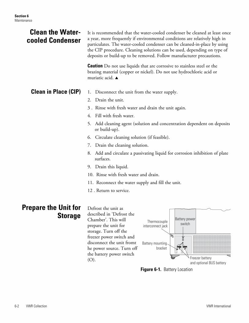
Defrost the unit asdescribed in ‘Defrost theChamber’. This willprepare the unit forstorage. Turn off thefreezer power switch anddisconnect the unit fromthe power source. Turn offthe battery power switch(O).
Prepare the Unit forStorage
Battery power
switchThermocouple
interconnect jack
Battery mounting
bracket
Freezer battery
and optional BUS battery
Figure 6-1. Battery Location

Caution To prevent permanent damage to the refrigeration system of thisfreezer, proper draining and preparation is required for long term storage.The water-cooled condenser must be dry and sealed. If stored clean anddry, restoring to service only requires a new in-line strainer filter, properinstallation and water flow balancing per ‘Water Cooled Condenser’. s
Required: Cleaning solution, supply of dry air or N2.
Note Do not use liquids corrosive to stainless steel or the brazing material(copper or nickel). Do not use hydrochloric acid or muriatic acid. s
1. Turn the freezer off.
2. Drain and clean the unit following the procedure in this section, CleanWater-cooled Condenser.
3. The condenser must be fully dry prior to storage. Use dry air to purgeand dry the condenser circuit as much as possible. Since the freezer isnot running, the internal valve will be closed and dry air cannot becirculated through the loop. Allow the condenser to dry, open to theair, until no moisture is seen at the connecting ports.
4. After the condenser water loop is dry, purge both the inlet and outletwith nitrogen or dry air and cap the ports.
Note On restarting a freezer that has been stored for some time, it issuggested to run the unit briefly, then check and clean the particulatefilter, if fitted, to ensure that no sediment or growth occurred in thecondenser during storage. s
1. Remove all product and place it in another freezer.
2. Turn the unit off and disconnect it from the power source.
3. Turn off the battery switch (O). See Figure 6-1.
4. Open all of the doors and place towels on the chamber floor.
5. Allow the frost to melt and become loose.
6. Remove the frost with a soft cloth.
7. After defrosting is complete, clean the interior with a non-chloridedetergent. Rinse thoroughly with clean water and dry with a soft cloth.
8. Plug unit in and turn power switch on.
9. Turn the battery power switch to Standby mode ( )
10. Allow the freezer to operate empty overnight before reloading theproduct.
VWR Collection 6-3VWR International
Section 6Maintenance
Defrost the Chamber
Long Term Storage withWater-cooled Condenser

Clean the door gasket a minimum of once a month.*
Using a soft cloth, remove any frost build-up from the gasket and door(s).The Clean Gasket alarm occurs every three months as a reminder toremove frost build-up from the gasket and door(s). Press the Silence key todisable the audible alarm.
*The door gasket may need to be cleaned more frequently if dirt or excessivefrost build-up prevents the door from closing properly.
The exterior door gasket provides an excellent seal that protects product,provides an energy efficient thermal barrier to keep cold air in and roomtemperature air out, and reduces frost build-up on the inner doors.
Because the door gasket seals so well, a vacuum can be created after a dooropening. Warm air enters the cabinet, cools and contracts, creating avacuum that pulls the door in tightly against the seal.
To equalize the pressure inside the cabinet after a door opening requires1.5-3.0 cu.ft. of ambient air to be drawn into the cabinet. The amount ofair required to equalize the pressure varies depending on the cabinet size,cabinet temperature, duration of door opening, inventory volume and thetemperature/humidity of the ambient air. This unit is designed with a“vacuum relief port” that allows the pressure to be equalized.
The time required to draw 1.5-3.0 cu.ft. of air into the cabinet depends ontwo. factors,
a) size and number of paths available for air to enter cabinet, and b) pressure difference between internal cabinet and ambient room.
Cabinets with the vacuum relief port operating normally, (i.e. vacuumrelief port is not iced over) will require a minimum of 30 seconds up to amaximum of 120 seconds for the cabinet to equalize. This is also a goodindication that the exterior door is well sealed.
The vacuum relief port requires routine maintenance. It will ice over unlesspreventive measures are taken. If the vacuum relief port becomes icedover, the freezer will take several hours to equalize pressure.
Caution Do not leave the freezer unattended while the door is unlatched.The vacuum could release at any time, resulting in the door opening andpossible product loss. s
6-4 VWR Collection VWR International
Section 6Maintenance
Vacuum Relief Port
Clean the DoorGasket
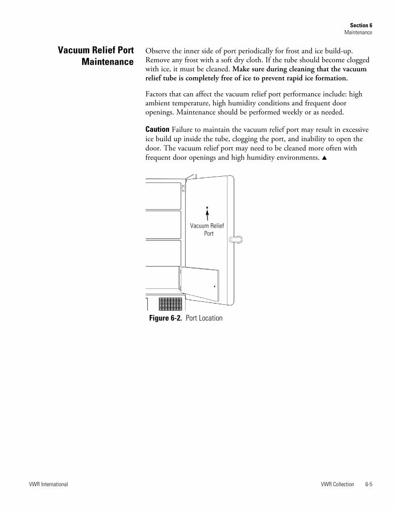
Observe the inner side of port periodically for frost and ice build-up.Remove any frost with a soft dry cloth. If the tube should become cloggedwith ice, it must be cleaned. Make sure during cleaning that the vacuumrelief tube is completely free of ice to prevent rapid ice formation.
Factors that can affect the vacuum relief port performance include: highambient temperature, high humidity conditions and frequent dooropenings. Maintenance should be performed weekly or as needed.
Caution Failure to maintain the vacuum relief port may result in excessiveice build up inside the tube, clogging the port, and inability to open thedoor. The vacuum relief port may need to be cleaned more often withfrequent door openings and high humidity environments. s
VWR Collection 6-5VWR International
Section 6Maintenance
Vacuum Relief PortMaintenance
Figure 6-2. Port Location
Vacuum ReliefPort

1. To gain access to the battery, open the lower door by grasping thebottom left corner. The battery is rectangular in shape, located on thefront left corner of the compressor compartment and is secured inplace by a mounting bracket.
2. Directly above the battery(s) is the battery power switch. Turn thebattery power switch to the off position (O).
3. Cut the tie wrap securing the battery to the mounting bracket. Lift thebattery out of the bracket.
4. Disconnect the red and black wires from the battery.
5. Use a voltmeter set to DC volts. Matching the wire colors, connect themeter to the battery.
6. If the voltage reads less than 10.8 volts, replace the battery. If above10.8, re-install as previously.
7. Turn the battery power switch to Standby mode ( ).
8. Close lower panel door.
1. To gain access to the battery, open the lower door by grasping thebottom left corner. The battery is rectangular in shape, located on thefront left corner of the compressor compartment and is secured inplace by a mounting bracket.
2. Directly above the battery(s) is the battery power switch. Turn thebattery power switch to the off position (O).
3. Disconnect the battery connections.
4. Remove the old battery and install the new battery.
6. Reconnect the battery (red to positive and black to negative).
7. Turn the battery power switch to Standby mode ( ).
8. Close lower panel door.
Warning The % of charge can vary depending on the age, usage andcondition of the battery. For a consistent and dependable charge, replacethe battery every 2 years. Replacement batteries must be rechargeable andare available from Thermo. Refer to the parts list for stock number anddescription of the replacement batteries. Dispose of the used batteries in asafe manner and in accordance with good environmental practices. s
6-6 VWR Collection VWR International
Section 6Maintenance
Check Battery
Replace the Battery

VWR Collection 6-7VWR International
Section 6Maintenance
PREV
ENTI
VE M
AIN
TEN
AN
CE
Tips
:

6-8 VWR Collection VWR International
Section 6Maintenance
Ref
er to
Man
ual
Sect
ion
Actio
n M
onth
ly
Year
ly
Ever
y 2
Year
s
Mor
e fre
quen
t cle
anin
g m
ay b
e re
quire
d, d
epen
ding
on
use
and
envi
ronm
enta
l con
ditio
ns.
To
min
imiz
e ic
e bu
ild-u
p in
side
free
zer:

Section 7 Factory Installed Options
Descriptions of freezer options which can only be factory installed follow.
Warning Before installation of BUS components, make sure the power tothe freezer is disconnected, the battery switch is turned off (O) and thefreezer has warmed to ambient temperature. s
The built-in BUS (back up system) will keep the freezer chambertemperature below the critical level in the event of a power or equipmentfailure. If power to the freezer fails, or temperature increases to the back upalarm set point, the BUS injects liquefied gas into the chamber to keep thechamber temperature within the specified range.
The BUS operates on an internal 12-volt, rechargeable battery which iskept charged during normal operation by the integral battery charger.
VWR Collection 7-1VWR International
Back-Up System (BUS)
Figure 7-1. Injection

1. Install the injection assembly through the 1/2” pre-punched hole,directly behind the 2” vent stack hole in the center of the chamberceiling.
Note Cover the open end of injection assembly with tape to keepinsulation from entering the nipple. s
2. Slide 3/8” flatwasher over open end of nipple.
3. Insert the covered end of the injection assembly through the exteriorhole.
4. Remove the tape covering from the end of the nipple and install the1/8” NPT brass tee on the open end of the nipple. Place Permagumsealant between the brass tee and the interior top.
5. Remove the two Phillips head screws securing the metal bracket on thevent stack assembly.
6. Install the vent stack through the opening and secure it to the top ofthe freezer, using screws.
7. Go to the interior and seal around the end of the vent stack withPermagum.
8. Install the transfer hose connecting one end to the injection assembly,the other end to the solenoid valve. Install the solenoid valve to thesupply source. The solenoid mounting bracket is not required and maybe discarded.
Caution When selecting aCO2 supply cylinder, it mustbe equipped with a siphontube. s
7-2 VWR Collection VWR International
Section 7Factory Installed Options
Install Vent Stack,Solenoid & Injection Asm.
Figure 7-2. Vent Stack

VWR Collection 7-3VWR International
Section 7Factory Installed Options
1. Locate the 0.500” pre-punched hole inthe upper left back corner of thechamber ceiling. Remove the tie wrapsecuring the coiled probe/solenoidharness. Uncoil the probe lead and runthe probe tip (approximately 12”)down through 0.500” porthole (Figure7-4).
2. As in Figure 7-3, thread the small tiewrap through the openings in thefront of the bracket. Secure the probeon the back of the bracket with thetie wrap.
3. Tap #8-32 the two pre-punched holes located on the interior left wallof the freezer. Mount the bracket. Figure 7-4 shows the Back-Upprobe mounted on the interior left side wall of the freezer.
Install the TemperatureProbe
290167
Back-Up Probe
30037
Small Tie
Wrap
195419
Probe Mounting
Bracket
Figure 7-3. Probe
Figure 7-4. Probe Bracket

1. Remove the four screws on the freezer back panel and use them tomount the tie wrap anchors as shown in Figure 7-5. Secure the probewire with tie wraps.
2. Plug the solenoid/probe connector into the BUS connection and securewith a screw on the right and left side. The connector is keyed.
3. Loosen the terminal screws on the solenoid. Slide the spade lugconnectors under the screws and tighten to secure.
4. Connect power to the freezer. Turn the freezer On, with battery switchOff (O).
a. The Solenoid Engaged light on the BUS control panel willilluminate (no injection occurs). This light stays on until the unit isbelow BUS setpoint.
b. The Low Battery indicator may also illuminate.
5. Turn the battery switch to Standby mode ( ) to charge both batteries.
7-4 VWR Collection VWR International
Section 7Factory Installed Options
Connect theProbe/Solenoid Harness
Remote alarmcontacts andanalog output
Power switch
(mains disconnect)
Power Inlet
RS-232 or RS-485Interface
BUS connection Spade lug
connections
to solenoid
Tie wrap
anchor
Probe wire
Figure 7-5. Connections
Warning When activated, this unit injects liquid nitrogen or carbondioxide. Liquid nitrogen can cause serious freezing (frostbite) if it comesin contact with unprotected skin or eyes. Nitrogen and carbon dioxide gassuppresses oxygen levels and may cause suffocation if area is not wellventilated. Refer to Appendix A for the proper handling of liquid LN2. s
Caution Make sure the pressure relief valve on any LN2 tank is adjusted to30 PSI max blow-off. s
Warning Carbon dioxide gas suppresses oxygen levels and may causesuffocation if area is not well ventilated. Refer to “Handling Liquid CO2
in Appendix B. s
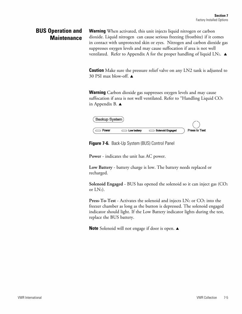
Power - indicates the unit has AC power.
Low Battery - battery charge is low. The battery needs replaced orrecharged.
Solenoid Engaged - BUS has opened the solenoid so it can inject gas (CO2
or LN2).
Press-To-Test - Activates the solenoid and injects LN2 or CO2 into thefreezer chamber as long as the button is depressed. The solenoid engagedindicator should light. If the Low Battery indicator lights during the test,replace the BUS battery.
Note Solenoid will not engage if door is open. s
VWR Collection 7-5VWR International
Section 7Factory Installed Options
BUS Operation andMaintenance
Figure 7-6. Back-Up System (BUS) Control Panel

The optional back up system is designed to inject CO2 or LN2 into thefreezer compartment if the temperature rises above back up system setpoint. To set the BUS set point:
1. Press the Mode key until the Settings indicator lights.
2. Press the right arrow until “BACKUP = -XX” is displayed in themessage center.
3. Press the up or down arrow key until the desired BUS set point isdisplayed.
4. Press Enter to save the setting.
5. Press the Mode key until the Run indicator lights or press the right orleft arrow to go to next or previous parameter.
If no control keys are pressed, the freezer automatically returns to RUNmode after 5 minutes.
Caution The BUS setpoint cannot be set any colder than the hightemperature alarm setpoint (see Section 1). If the back-up system isinstalled with CO2, then -65°C is the coldest BUS setpoint that can beused (if the cabinet setpoint is -75°C or colder).Changing the operating temperature setpoint can affect the BUS setpoint.The BUS setpoint will self-adjust to maintain a temperature of at least10°C above the operating temperature setpoint. s
After the freezer has stabilized and both batteries are fully charged, theBUS can be tested to verify proper operation.
1. Disconnect the AC power to the freezer by turning the power switchoff.
2. As the freezer warms up, verify the BUS injects at the desiredtemperature. Displayed temperature may vary by a few degrees frominject temperature due to the differences in probe locations.
Routinely check the vent stack for frost or ice build-up. The type of frostthat forms in the vent stack is generally very soft and may be easilyremoved with a bristle brush or soft cloth. If ice build-up has occurred, acomplete defrost may occasionally be required. See Section 5 for freezerdefrost instructions.
7-6 VWR Collection VWR International
Section 7Factory Installed Options
Set Optional BUS Setpoint
Test the BUS
Clean the Vent Stack

To disconnect the freezer back-up from the gas supply:
1. Close the supply valve.
2. Depress the test button on the Back-Up System control box to removethe gas from the line.
3. Slowly disconnect the fitting assembly from the supply (in the eventthat any gas remains in the line).
To install the chart paper in the recorder, follow the steps below.
1. Open the glass door of the recorder and press button #3 until the penbegins to move outward.
2. Unscrew the knob at the center of the chart and remove the paper.
3. Install the new chart paper, position the paper to the correct time lineand replace the knob.
4. Remove the cap from the felt pen and press button #3.
VWR Collection 7-7VWR International
Section 7Factory Installed Options
Disconnect the Fitting Assemblyand Transfer Hose
Chart Recorder
1 2
3Program selection and
calibration buttons
Range Sticker
1 2
3G
OO
D
LO
W
1
2
3 4 5
6
7
8
Figure 7-7. Recorder Details
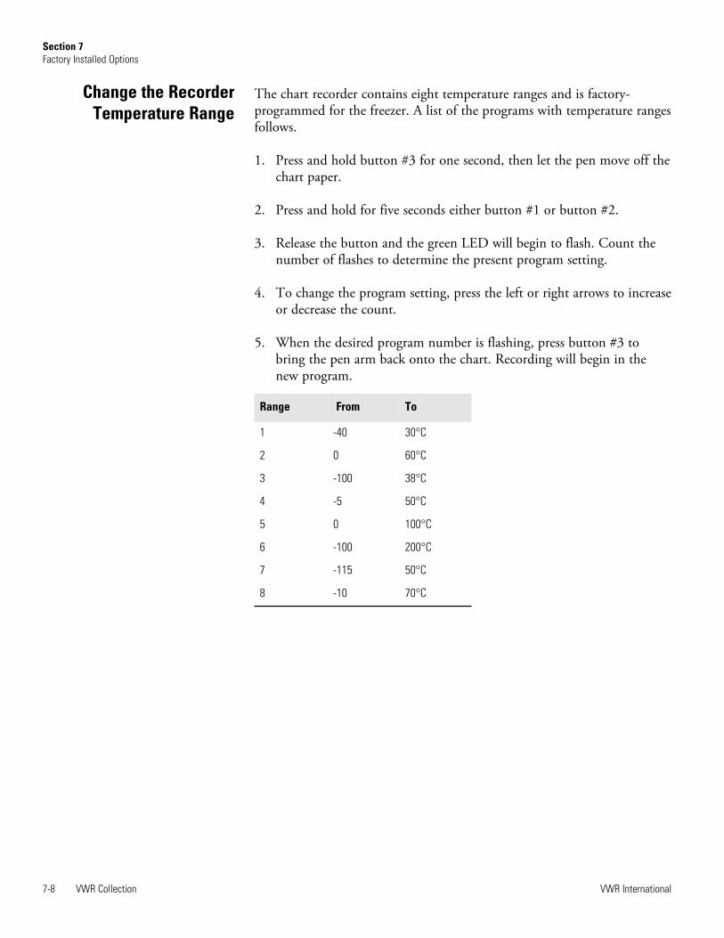
The chart recorder contains eight temperature ranges and is factory-programmed for the freezer. A list of the programs with temperature rangesfollows.
1. Press and hold button #3 for one second, then let the pen move off thechart paper.
2. Press and hold for five seconds either button #1 or button #2.
3. Release the button and the green LED will begin to flash. Count thenumber of flashes to determine the present program setting.
4. To change the program setting, press the left or right arrows to increaseor decrease the count.
5. When the desired program number is flashing, press button #3 tobring the pen arm back onto the chart. Recording will begin in thenew program.
7-8 VWR Collection VWR International
Section 7Factory Installed Options
Range From To
1 -40 30°C
2 0 60°C
3 -100 38°C
4 -5 50°C
5 0 100°C
6 -100 200°C
7 -115 50°C
8 -10 70°C
Change the RecorderTemperature Range

Caution The recorder must be in service for 24 hours before performingthe following calibration procedure. s
1. Place an accurate thermometer in the chamber next to the recorderprobe.
2. Temperature probes for the recorder are located in the left front cornerof the freezer chamber (Figure 1-4).
3. After about three minutes, compare the thermometer reading with thechart recorder reading.
4. If an adjustment is necessary, press the #1 button to move the pen tothe left or the #2 to move the pen to the right. The button must beheld about five seconds before the pen begins to move. Release thebutton when the pen position matches the thermometer.
Note The felt-tip pen on the recorder requires periodic replacement.Usually the ink will appear to fade before replacement becomes necessary.Additional pen tips are available for purchase. s
VWR Collection 7-9VWR International
Section 7Factory Installed Options
Calibrate the Recorder

The water-cooled condenser is a factory installed option (P/N 195964,195965, 195967) and requires a qualified technician at freezer installation.Refer to Table 7-1 for the specifications for this option.
Water Quality: Free of particulates that could cause a blockage, or impairfunction of the regulating valve or heat exchanger. A stainless steel inlinestrainer is factory installed in the inlet pipe to minimize particulates in thewater supply.
Water Drainage: If water return line labeled WATER OUTLET is notconnected to a closed loop chiller system, connect the return line water toa reservoir tank or drain. This will hold/dispose of the water from thefreezer to avoid flooding.
To verify operating requirements, you will need:
• a flowmeter capable of measuring up to at least 5.3 gallons (20 liters)per minute to measure flow rates at the water return line labeledWATER OUTLET.
• a pressure gauge ranging from 0 to 300 psig to measure pressure at thewater inlet labeled WATER INLET.
• a thermocouple or other temperature monitor to measure the watertemperature near the water inlet fitting labeled WATER INLET.
Clearance: Before installing the water connections, position the freezerwith an extra 2 inches (5cm) clearance in back for a hose. This is inaddition to the 6 inches (15cm) clearance in back previously recommendedin this manual.
7-10 VWR Collection VWR International
Section 7Factory Installed Options
Water-cooledCondenser
Water Pressure Not to exceed 90 psig (620.5 kpa)
Water Temperature Range Not to exceed 29.4°C (85°F)
Inlet Connection 1/2” NPT
Outlet Connection 1/2” NPT
Flow Rate Required (minimum) 1.0 gallons (3.8 liters) per minute
Table 7-1. Specifications

Caution When using multiple freezers in a water loop, proper water flowand inlet temperature must be maintained for EACH freezer in the loop.It is recommended that a valve be installed in the supply line of eachfreezer to facilitate a balanced flow rate.If the number of freezers in a loop is more than 5, it is recommended thatone freezer be started at a time and tested to verify water flow, beforestarting all and allowing to run. Water flow of at least 1 gpm, at or belowthe maximum allowed inlet temperature, is required. Values higher thanminimum are acceptable. Do not allow the freezer to continue to runwith no observed water flow within several seconds of the compressorstarting. s
Recommended Bypass Water Loop Assembly: The bypass loop containsfittings, a valve, and a flowmeter to simulate the presence of a freezer andallows for balancing of the entire water supply system to ensure that 1 gpmis available for each freezer in the loop before the freezers are started.Values higher than minimum are acceptable. Do not adjust the valveinside the deck of the freezer. It is pre-set at the factory.
Option A: Install the bypass instead of a freezer (Figure 7-8).
Option B: Install the bypass permanently (Figure 7-8) so that allfreezers can be left connected but water flow can be simulated usingthe bypass without turning on all freezers.
Caution If Option B is used, the bypass valve MUST be closed prior tofreezer operation to ensure all water passes through the freezer rather thanthe bypass. Failure to do this will result in damage to the freezer.
VWR Collection 7-11VWR International
Section 7Factory Installed Options
Water-cooledCondenser (cont.)
Figure 7-8. Bypass Water Loop Options
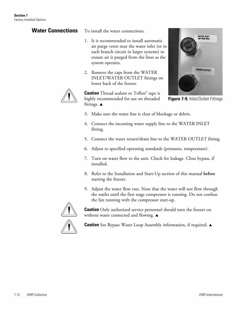
To install the water connections:
1. It is recommended to install automaticair purge vents near the water inlet (or ineach branch circuit in larger systems) toensure air is purged from the lines as thesystem operates.
2. Remove the caps from the WATERINLET/WATER OUTLET fittings onlower back of the freezer.
Caution Thread sealant or Teflon® tape ishighly recommended for use on threadedfittings. s
3. Make sure the water line is clear of blockage or debris.
4. Connect the incoming water supply line to the WATER INLETfitting.
5. Connect the water return/drain line to the WATER OUTLET fitting.
6. Adjust to specified operating standards (pressures, temperature).
7. Turn on water flow to the unit. Check for leakage. Close bypass, ifinstalled.
8. Refer to the Installation and Start-Up section of this manual beforestarting the freezer.
9. Adjust the water flow rate. Note that the water will not flow throughthe outlet until the first stage compressor is running. Do not confusethe fan running with the compressor start-up.
Caution Only authorized service personnel should turn the freezer onwithout water connected and flowing. s
Caution See Bypass Water Loop Assembly information, if required. s
7-12 VWR Collection VWR International
Section 7Factory Installed Options
Figure 7-9. Inlet/Outlet Fittings
Water Connections

VWR Collection 8-1VWR International
Section 8Warranty Information
VW
R S
CIE
NT
IFIC
PR
OD
UC
TS
FR
EE
ZE
R W
AR
RA
NT
Y -
US
A
The W
arr
anty
Period s
tart
s t
wo w
eeks f
rom
the d
ate
your
equip
ment
is s
hip
ped f
rom
our
facili
ty.
This
allo
ws f
or
ship
pin
g t
ime
so t
he w
arr
anty
will
go into
effect
at
appro
xim
ate
ly t
he s
am
e t
ime y
our
equip
ment
is d
eliv
ere
d.
The w
arr
anty
pro
tection
exte
nds t
o a
ny s
ubsequent
ow
ner
during t
he w
arr
anty
period.
During t
he f
irst
two y
ears
of
the w
arr
anty
period,
com
ponent
part
s p
roven t
o b
e n
on-c
onfo
rmin
g in m
ate
rials
or
work
manship
will
be r
epaired o
r re
pla
ced a
t V
WR
/Therm
o S
cie
ntific’s
expense,
labor
inclu
ded.
The V
WR
Colle
ction U
LT
Fre
ezers
inclu
de
an a
dditio
nal th
ree y
ear
warr
anty
on t
he c
om
pre
ssors
, part
s o
nly
, F.O
.B.
facto
ry.
Insta
llation a
nd c
alib
ration is n
ot
covere
d b
y
this
warr
anty
agre
em
ent. T
he T
echnic
al S
erv
ices D
epart
ment
must
be c
onta
cte
d f
or
warr
anty
dete
rmin
ation a
nd d
irection
prior
to a
ny w
ork
bein
g p
erf
orm
ed.
Expendable
ite
ms,
i.e., g
lass,
filters
, pilo
t lig
hts
, lig
ht
bulb
s a
nd d
oor
gaskets
are
exclu
d-
ed f
rom
this
warr
anty
.
Repla
cem
ent
or
repair o
f com
ponent
part
s o
r equip
ment
under
this
warr
anty
shall
not
exte
nd t
he w
arr
anty
to e
ither
the
equip
ment
or
to t
he c
om
ponent
part
beyond t
he o
rigin
al tw
o y
ear
warr
anty
period.
VW
R a
nd/o
r T
herm
o m
ust
giv
e p
rior
appro
val fo
r th
e r
etu
rn o
f any c
om
ponents
or
equip
ment.
TH
IS W
AR
RA
NT
Y I
S E
XC
LU
SIV
E A
ND
IN
LIE
U O
F A
LL O
TH
ER
WA
RR
AN
TIE
S,
WH
ET
HE
R W
RIT
TE
N,
OR
AL,
OR
IMP
LIE
D.
NO
WA
RR
AN
TIE
S O
F M
ER
CH
AN
TA
BIL
ITY
OR
FIT
NE
SS
FO
R A
PA
RT
ICU
LA
R P
UR
PO
SE
SH
ALL A
PP
LY.
VW
R/T
herm
o s
hall
not
be lia
ble
for
any indirect
or
consequential dam
ages inclu
din
g,
without
limitation,
dam
ages r
ela
ting t
o
lost
pro
fits
or
loss o
f pro
ducts
.
Your
local V
WR
Sale
s O
ffic
e is r
eady t
o h
elp
with c
om
pre
hensiv
e s
ite p
repara
tion info
rmation b
efo
re y
our
equip
ment
arr
ives.
Printe
d instr
uction m
anuals
care
fully
deta
il equip
ment
insta
llation,
opera
tion,
and p
reventive m
ain
tenance.
If e
quip
ment
serv
ice is r
equired,
ple
ase c
all
the T
echnic
al S
erv
ices O
ffic
e a
t 1-8
00-4
38-4
851 (
US
A a
nd C
anada)
or
1-7
40-3
73-4
763.
We're r
eady t
o a
nsw
er
your
questions o
n e
quip
ment
warr
anty
, opera
tion,
main
tenance,
serv
ice,
and s
pecia
l
applic
ations.
Outs
ide t
he U
SA
, conta
ct
your
local dis
trib
uto
r fo
r w
arr
anty
info
rmation.
ISO
9001
REGI
STER
EDR
ev.
7 1
/15

8-2 VWR Collection VWR International
Section 8Warranty Information
VW
R S
CIE
NT
IFIC
PR
OD
UC
TS
FR
EE
ZE
R W
AR
RA
NT
Y -
IN
TE
RN
AT
ION
AL
The W
arr
anty
Period s
tart
s t
wo m
onth
s f
rom
the d
ate
your
equip
ment
is s
hip
ped f
rom
our
facili
ty.
This
allo
ws f
or
ship
pin
g
tim
e s
o t
he w
arr
anty
will
go into
effect
at
appro
xim
ate
ly t
he s
am
e t
ime y
our
equip
ment
is d
eliv
ere
d.
The w
arr
anty
pro
tection
exte
nds t
o a
ny s
ubsequent
ow
ner
during t
he w
arr
anty
period.
During t
he f
irst
two y
ears
of
the w
arr
anty
period,
com
ponent
part
s p
roven t
o b
e n
on-c
onfo
rmin
g in m
ate
rials
or
work
manship
will
be r
epaired o
r re
pla
ced a
t V
WR
/Therm
o S
cie
ntific's
expense,
labor
exclu
ded.
The V
WR
Colle
ction F
reezers
inclu
de a
n
additio
nal th
ree y
ear
warr
anty
on t
he c
om
pre
ssors
, part
s o
nly
, F.O
.B.
facto
ry.
Insta
llation a
nd c
alib
ration is n
ot
covere
d b
y
this
warr
anty
agre
em
ent. T
he T
echnic
al S
erv
ices D
epart
ment
must
be c
onta
cte
d f
or
warr
anty
dete
rmin
ation a
nd d
irection
prior
to a
ny w
ork
bein
g p
erf
orm
ed.
Expendable
ite
ms,
i.e., g
lass,
filters
, pilo
t lig
hts
, lig
ht
bulb
s a
nd d
oor
gaskets
are
exclu
ded
from
this
warr
anty
.
Repla
cem
ent
or
repair o
f com
ponent
part
s o
r equip
ment
under
this
warr
anty
shall
not
exte
nd t
he w
arr
anty
to e
ither
the
equip
ment
or
to t
he c
om
ponent
part
beyond t
he o
rigin
al tw
o y
ear
warr
anty
period.
VW
R a
nd/o
r T
herm
o m
ust
giv
e p
rior
appro
val fo
r th
e r
etu
rn o
f any c
om
ponents
or
equip
ment.
TH
IS W
AR
RA
NT
Y I
S E
XC
LU
SIV
E A
ND
IN
LIE
U O
F A
LL O
TH
ER
WA
RR
AN
TIE
S,
WH
ET
HE
R W
RIT
TE
N,
OR
AL,
OR
IMP
LIE
D.
NO
WA
RR
AN
TIE
S O
F M
ER
CH
AN
TA
BIL
ITY
OR
FIT
NE
SS
FO
R A
PA
RT
ICU
LA
R P
UR
PO
SE
SH
ALL A
PP
LY.
VW
R/T
herm
o s
hall
not
be lia
ble
for
any indirect
or
consequential dam
ages inclu
din
g,
without
limitation,
dam
ages r
ela
ting t
o
lost
pro
fits
or
loss o
f pro
ducts
.
Your
local V
WR
Sale
s O
ffic
e is r
eady t
o h
elp
with c
om
pre
hensiv
e s
ite p
repara
tion info
rmation b
efo
re y
our
equip
ment
arr
ives.
Printe
d instr
uction m
anuals
care
fully
deta
il equip
ment
insta
llation,
opera
tion,
and p
reventive m
ain
tenance.
If e
quip
ment
serv
ice is r
equired,
ple
ase c
all
your
local dis
trib
uto
r or
the T
echnic
al S
erv
ices D
epart
ment
at
1-7
40-3
73-4
763
(1-8
00-4
38-4
851 in U
SA
or
Canada).
We're r
eady t
o a
nsw
er
your
questions o
n e
quip
ment
warr
anty
, opera
tion,
main
tenance,
serv
ice,
and s
pecia
l applic
ations.
Outs
ide t
he U
SA
, conta
ct
your
local dis
trib
uto
r fo
r w
arr
anty
info
rmation.
ISO
9001
REGI
STER
EDR
ev.
7 1
/15

VWR Collection A-1VWR International
Appendix A Handling Liquid Nitrogen
Warning Contact of liquid nitrogen or cold gas with the skin or eyes maycause serious freezing (frostbite) injury. s
Handle liquid nitrogen carefully.The extremely low temperature can freeze human flesh very rapidly.When spilled on a surface the liquid tends to cover it completely andintimately, cooling a large area. The gas issuing from the liquid is alsoextremely cold. Delicate tissue, such as that of the eyes, can be damagedby an exposure to the cold gas which would be too brief to affect theskin of the hands or face.
Never allow any unprotected part of your body to touch objects cooledby liquid nitrogen.Such objects may stick fast to the skin and tear the flesh when youattempt to free yourself. Use tongs to withdraw objects immersed in theliquid, and handle the object carefully.
Wear protective clothing.Protect your eyes with a face shield or safety goggles (safety glasses with-out side shields do not give adequate protection). Always wear gloveswhen handling anything that is, or may have been, in immediate contactwith liquid nitrogen. Insulated gloves are recommended, but heavyleather gloves may also be used. The gloves should fit loosely, so thatthey can be thrown off quickly if liquid should splash into them. Whenhandling liquid in open containers, it is advisable to wear high-topshoes. Trousers (which should be cuffless if possible) should be wornoutside the shoes.

VWR International
The safe handling and use of liquid nitrogen in cryogenic refrigerators anddewar flasks is largely a matter of knowing the potential hazards and usingcommon-sense procedures based on that knowledge. There are twoimportant properties of liquid nitrogen that present potential hazards:
1. It is extremely cold. At atmospheric pressure, liquid nitrogen boils at -320°F (-196°C).
2. Very small amounts of liquid vaporize into large amounts of gas. Oneliter of liquid nitrogen becomes 24.6 cu. ft. (700l) of gas.
The safety precautions in this booklet must be followed to avoid potentialinjury or damage which could result from these two characteristics. Donot attempt to handle liquid nitrogen until you read and fully understandthe potential hazards, their consequences, and the related safetyprecautions. Keep this booklet handy for ready reference and review.
Note Argon is an inert gas whose physical properties are very similar tothose of nitrogen. The precautions and safe practices for the handling anduse of liquid argon are the same as those for liquid nitrogen. s
Use only containers designed for low temperature liquids.Cryogenic containers are specifically designed and made of materials thatcan withstand the rapid changes and extreme temperature differencesencountered in working with liquid nitrogen. Even these special con-tainers should be filled SLOWLY to minimize the internal stresses thatoccur when any material is cooled. Excessive internal stresses can dam-age the container.
Do not cover or plug the entrance opening of any liquid nitrogen refrig-erator or dewar. Do not use any stopper or other device that wouldinterfere with venting of gas. These cryogenic liquid containers are generally designed to operate withlittle or no internal pressure. Inadequate venting can result in excessivegas pressure which could damage or burst the container. Use only theloose-fitting necktube core supplied or one of the approved accessoriesfor closing the necktube. Check the unit periodically to be sure thatventing is not restricted by accumulated ice or frost.
Use proper transfer equipment. Use a phase separator or special filling funnel to prevent splashing andspilling when transferring liquid nitrogen into or from a dewar or refrig-erator. The top of the funnel should be partly covered to reduce splash-ing. Use only small, easily-handled dewars for pouring liquid. For thelarger, heavier containers, use a cryogenic liquid withdrawal device totransfer liquid from one container to another. Be sure to follow instruc-tions supplied with the withdrawal device. When liquid cylinders orother large storage containers are used for filling, follow the instructionssupplied with those units and their accessories.
A-2 VWR Collection
Introduction
Appendix

VWR International VWR Collection A-3
Appendix
Do not overfill containers.Filling above the bottom of the necktube (or specified maximum level)can result in overflow and spillage of liquid when the necktube core orcover is placed in the opening.
Never use hollow rods or tubes as dipsticks.When a warm tube is inserted into liquid nitrogen, liquid will spoutfrom the top of the tube due to gasification and rapid expansion of liq-uid inside the tube.
Warning Nitrogen gas can cause suffocation without warning! s
Store and use liquid nitrogen only in a well-ventilated place. As the liquid evaporates, the resulting gas tends to displace the normalair from the area. In closed areas, excessive amounts of nitrogen gasreduce the concentration of oxygen and can result in asphyxiation.Because nitrogen gas is colorless, odorless and tasteless, it cannot bedetected by the human senses and will be breathed as if it were air.Breathing an atmosphere that contains less than 18% oxygen can causedizziness and quickly result in unconsciousness and death.
Note The cloudy vapor that appears when liquid nitrogen is exposed tothe air is condensed moisture; not the gas itself. The issuing gas isinvisible. s
Never dispose of liquid nitrogen in confined areas or places where othersmay enter.Disposal of liquid nitrogen should be done outdoors in a safe place.Pour the liquid slowly on gravel or bare earth where it can evaporatewithout causing damage. Do not pour the liquid on pavement.
Introduction(continued)

VWR International
First Aid
Warning High concentrations of CO2 gas can cause asphyxiation! OSHAStandards specify that employee exposure to carbon dioxide in any eight-hour shift of a 40-hour work week shall not exceed the eight-hour timeweighted average of 5000 PPM (0.5% CO2). The short term exposurelimit for 15 minutes or less is 30,000 PPM (3% CO2). Carbon dioxidemonitors are recommended for confined areas where concentrations ofcarbon dioxide gas can accumulate. s
Store and use liquid CO2 only in a well-ventilated place.As the liquid evaporates, the resulting gas tends to displace the normalair from the area. In closed areas, excessive amounts of CO2 gas reducethe concentration of oxygen and can result in asphyxiation. BecauseCO2 gas is colorless, odorless and tasteless, it cannot be detected by thehuman senses and will be breathed as if it were air. Breathing an atmos-phere that contains less than 18% oxygen can cause dizziness and quicklyresult in unconsciousness and death.
Note The cloudy vapor that appears when liquid CO2 is exposed to the airis condensed moisture, not the gas itself. The issuing gas is invisible. s
Never dispose of liquid CO2 in confined areas or places where others mayenter.Disposal of liquid CO2 should be done outdoors in a safe place. Pourthe liquid slowly on gravel or bare earth where it can evaporate withoutcausing damage. Do not pour the liquid on pavement.
If a person seems to become dizzy or loses consciousness while workingwith liquid nitrogen or carbon dioxide, move to a well-ventilated areaimmediately. If breathing has stopped, apply artificial respiration. Ifbreathing is difficult, give oxygen. Call a physician. Keep warm and atrest.
If exposed to liquid or cold gas, restore tissue to normal body temperature(98.6° F) as rapidly as possible, followed by protection of the injured tissuefrom further damage and infection. Remove or loosen clothing that mayconstrict blood circulation to the frozen area. Call a physician. Rapidwarming of the affected part is best achieved by using water at 108° F.Under no circumstance should the water be over 112° F, nor should thefrozen part be rubbed either before or after rewarming. The patient shouldneither smoke nor drink alcohol.
A-4 VWR Collection
Handling LiquidCarbon Dioxide
Appendix

VWR Collection A-5VWR International
Austria VWR International GmbH Graumanngasse 7 1150 Vienna Tel.: +43 1 97 002 0 Fax: +43 1 97 002 600 E-mail: [email protected]
Belgium VWR International bvba Researchpark Haasrode 2020 Geldenaaksebaan 464 3001 Leuven Tel.: 016 385 011 Fax: 016 385 385 E-mail: [email protected]
Czech Republic VWR International s. r. o. Veetee Business Park Pražská 442 CZ - 281 67 St íbrná Skalice Tel.: +420 321 570 321 Fax: +420 321 570 320 E-mail: [email protected]
Denmark VWR - Bie & Berntsen Transformervej 8 2730 Herlev Tel.: 43 86 87 88 Fax: 43 86 87 90 E-mail: [email protected]
Finland VWR International Oy Valimotie 9 00380 Helsinki Tel.: 09 80 45 51 Fax: 09 80 45 52 00 E-mail: [email protected]
France VWR International S.A.S. Le Périgares – Bâtiment B 201, rue Carnot 94126 Fontenay-sous-Bois cedex Tel.: 0 825 02 30 30 (0,15 € TTC/min) Fax: 0 825 02 30 35 (0,15 € TTC/min) E-mail: [email protected]
Germany VWR International GmbH Hilpertstraße 20a D - 64295 Darmstadt Freecall: 0800 702 00 07 Fax: 0180 570 22 22* Email: [email protected] *0,14 €/Min. aus d. dt. Festnetz
Hungary VWR International Kft. Simon László u. 4. 4034 Debrecen Tel.: (52) 521-130 Fax: (52) 470-069 E-mail: [email protected]
Ireland / Northern Ireland VWR International Ltd / VWR International (Northern Ireland) Ltd Orion Business Campus Northwest Business Park Ballycoolin Dublin 15 Tel.: 01 88 22 222 Fax: 01 88 22 333 E-mail: [email protected]
Italy VWR International PBI S.r.l. Via San Giusto 85 20153 Milano (MI) Tel.: 02-3320311/02-487791 Fax: 800 152999/02-40090010 E-mail: [email protected]
The Netherlands VWR International B.V. Postbus 8198 1005 AD Amsterdam Tel.: 020 4808 400 Fax: 020 4808 480 E-mail: [email protected]
Norway VWR International AS Haavard Martinsens vei 30 0978 Oslo Tel.: 02290 Fax: 815 00 940 E-mail: [email protected]
Poland VWR International Sp. z o.o. Limbowa 5 80-175 Gdansk Tel.: 058 32 38 200 do 204 Fax. 058 32 38 205 E-mail: [email protected]
Portugal VWR International - Material de Laboratório, Lda Edifício Neopark Av. Tomás Ribeiro, 43- 3 D 2790-221 Carnaxide Tel.: 21 3600 770 Fax: 21 3600 798/9 E-mail: [email protected]
Spain VWR International Eurolab S.L. C/ Tecnología 5-17 A-7 Llinars Park 08450 - Llinars del Vallès Barcelona Tel.: 902 222 897 Fax: 902 430 657 E-mail: [email protected]
Sweden VWR International AB Fagerstagatan 18a 163 94 Stockholm Tel.: 08 621 34 00 Fax: 08 621 34 66 E-mail: [email protected]
Switzerland VWR International GmbH Lerzenstrasse 16/18 8953 Dietikon Tel.: 044 745 13 13 Fax: 044 745 13 10 E-mail: [email protected]
Turkey Pro Lab Laboratuar Teknolojileri Ltd. ti. a VWR International Company Orta Mah. Cemal Gürsel Caddesi Ördekcioglu I merkezi No.32/1 34896 Pendik - Istanbul Tel.: +90216 598 2900 Fax: +90216 598 2907 Email: [email protected]
UK VWR International Ltd Customer Service Centre Hunter Boulevard - Magna Park Lutterworth Leicestershire LE17 4XN Tel.: 0800 22 33 44 Fax: 01455 55 85 86 E-mail: [email protected]
Australia VWR International, Pty Ltd. Unit 1/31 Archimedes Place Murarrie, Queensland 4172 Tel.: 1300 727 696 Fax: 1300 135 123
China VWR International China Co., Ltd Rm.219, 2100 Dongming Road Pudong New District Shanghai 200123 Tel.:+86-21-5898 6888 Fax:+86-21-5855 8801 E-mail: [email protected]
India VWR Lab Products Private Limited 135/12, Brigade Towers, 2nd Floor Front wing, Brigade Road, Bengaluru, India – 560 025 Tel.: +91-80-41117125/26 (Bengaluru) Tel.: +91-2522-647911/922 (Mumbai) Fax: +91-80-41117120 E-mail: [email protected]
New Zealand Global Science - A VWR Company 241 Bush Road Albany 0632, Auckland Tel.: 0800 734 100 Fax: 0800 999 002 E-mail: [email protected]
Singapore VWR Singapore Pte Ltd 18 Gul Drive Singapore 629468 Tel.: +65 6505 0760 Fax: +65 6264 3780 E-mail: [email protected]


VWR International, Inc.1310 Goshen ParkwayWest Chester, Pennyslvania 19380U.S.A.