VT-VPCD – Digital closed loop control Replaces: 08.06 ...
108
The Drive & Control Company VT-VPCD – Digital closed loop control electronics for axial piston pumps A4VS... with HS4 control and A2V with EO4 control Installation and Operation RE 30028-01-B/08.07 Replaces: 08.06
Transcript of VT-VPCD – Digital closed loop control Replaces: 08.06 ...

The Drive & Control Company
VT-VPCD – Digital closed loop control electronics for axial piston pumps A4VS... with HS4 control and A2V with EO4 control
Installation and Operation
RE 30028-01-B/08.07Replaces: 08.06
2/106 Bosch Rexroth AG | Hydraulics Instruction Manual | RE 30028-01-B/08.07
Contents
1 Introduction................................................................................................6
1.1 Document ....................................................................................................6
1.2 General ........................................................................................................6
1.3 Signs and symbols used in this document...................................................6
1.4 Introduction to the Control assignment ........................................................7 Controlling the axial piston pump ................................................................................. 7 General definition of the assignment ............................................................................ 7 General description of the solution ............................................................................... 8
2 Pump control for A4VS…HS4 Pumps - Overview...................................9
2.1 General ........................................................................................................9
2.2 System components ....................................................................................9
2.3 Electrical and hydraulic installation plan ....................................................11 Connector pin assignments ........................................................................................ 14 Connecting the pressure transducers......................................................................... 17 Connecting the proportional valve .............................................................................. 18 Connecting the valve position transducer................................................................... 19 Connecting the swivel angle transducer..................................................................... 20
A4VS...HS4: Typ AWXF004D01 ........................................................................ 20 A2V...EO4 submergeable pump: Type DK100 ................................................... 20 A2V...EO4 Housing pump: Typ MCP-40/4742 ................................................... 21
2.4 Controller faceplate elements ....................................................................22
2.5 Circuit variations ........................................................................................25 Hydraulic circuit variations.......................................................................................... 25 Pump combination (MASTER / SLAVE)..................................................................... 26
2.6 Safety notes...............................................................................................29
3 Application: Pump control for A4VS…HS- pumps ...............................30

RE 30028-01-B/08.07 | Instuction Manual Hydraulics | Bosch Rexroth AG 3/106
3.1 Structured list for proceeding with start-up ................................................30
3.2 Configure application sequence ................................................................31 Data exchange between the BODAC software and the VT-VPCD controller card ..... 31 Open or create parameter file..................................................................................... 31
3.3 Configure inputs.........................................................................................32 Swivel angle command value..................................................................................... 32 Pressure command value........................................................................................... 33 Power command value............................................................................................... 33 Actual pressure B ....................................................................................................... 33 Actual pressure A ....................................................................................................... 34 res. Swivel angle command value .............................................................................. 34 MCP-40/4742 (Potentiometer-A2V)............................................................................ 34 Adjust input elements ................................................................................................. 34
3.4 Configure profiles.......................................................................................35 Command value configuration.................................................................................... 35 Configuration 1 ........................................................................................................... 39
Set null points for valve and pump position transducers..................................... 40 Pressure controller ..................................................................................................... 42 Enhanced pressure controller..................................................................................... 45 Motion data................................................................................................................. 49 Faults ......................................................................................................................... 49 Test jacks ................................................................................................................... 51 Configuration 3 ........................................................................................................... 51 Open Loop.................................................................................................................. 54 Bus Configuration....................................................................................................... 55 Bus Trigger................................................................................................................. 57 Busmanager (Profibus, CANopen, DeviceNet)........................................................... 58 Local Bus ................................................................................................................... 61
3.5 Define controller parameters .....................................................................62 Parameterizing the pressure controller....................................................................... 63
3.6 Save parameter file....................................................................................65
3.7 Check Application settings.........................................................................65 Test jacks ................................................................................................................... 65 Motion Data ................................................................................................................ 65 Status overview.......................................................................................................... 66
3.8 Start application .........................................................................................66

4/106 Bosch Rexroth AG | Hydraulics Instruction Manual | RE 30028-01-B/08.07
4 User interface BODAC - General ............................................................67
4.1 Software tool and data handling ................................................................67 The BODAC Software ................................................................................................ 67 Data exchange between BODAC and the VPCD ....................................................... 67 Create file ................................................................................................................... 67 Save the current status .............................................................................................. 68
4.2 Main Menu .................................................................................................68 Title bar ...................................................................................................................... 69 Menu bar .................................................................................................................... 69 BODAC toolbar........................................................................................................... 69 Window toolbar........................................................................................................... 70 Status bar ................................................................................................................... 71 Short cut list................................................................................................................ 71
5 BODAC – Menu Description ...................................................................73
5.1 File menu ...................................................................................................73 Open .......................................................................................................................... 73 Save ........................................................................................................................... 73 Printer Setup .............................................................................................................. 74 Print............................................................................................................................ 74 Quit............................................................................................................................. 74
5.2 Controller menu .........................................................................................75 Offline......................................................................................................................... 75 Connect ...................................................................................................................... 75 Search Card ............................................................................................................... 76 Read parameters........................................................................................................ 76 Write Parameters ....................................................................................................... 76 Set parameters to memory......................................................................................... 77 Language ................................................................................................................... 77 Card information......................................................................................................... 78
5.3 View menu .................................................................................................79 Status ......................................................................................................................... 80 Fault History ............................................................................................................... 81
5.4 Configuration menu ...................................................................................82 Analog I/O .................................................................................................................. 82
“Inputs” field........................................................................................................ 82

RE 30028-01-B/08.07 | Instuction Manual Hydraulics | Bosch Rexroth AG 5/106
5.5 Tools menu ................................................................................................84 Preferences ................................................................................................................ 84
Com.................................................................................................................... 84 Options ............................................................................................................... 87 Security .............................................................................................................. 90
Utilities........................................................................................................................ 92
5.6 Application Window menu .........................................................................93 Command values ....................................................................................................... 93 Configuration 1 ........................................................................................................... 93 Pressure controller ..................................................................................................... 93 Motion Data ................................................................................................................ 93 Multiplot ...................................................................................................................... 95
Multiplot toolbar .................................................................................................. 96 Multiplot signal display........................................................................................ 98 Multiplot signal display legend............................................................................ 98
Winview recording .................................................................................................... 100 Faults ....................................................................................................................... 101 Test jacks ................................................................................................................. 102 Configuration 3 ......................................................................................................... 103 Open Loop................................................................................................................ 103 Bus Configuration..................................................................................................... 103 Bus Trigger............................................................................................................... 103
5.7 Windows menu ........................................................................................104 Select an opened window ........................................................................................ 104 Save layout............................................................................................................... 104 Open layout .............................................................................................................. 104
5.8 Help menu ...............................................................................................105 About BODAC…....................................................................................................... 105 Topics....................................................................................................................... 105 Examples ................................................................................................................. 105

6/106 Bosch Rexroth AG | Hydraulics Instuction Manual | RE 30028-01-B/08.07
1 Introduction
1 Introduction
1.1 Document
Version 1.5
1.2 General
In this manual you will become familiar with:
The digital controller for axial piston displacement pumps VT-VPCD
The BODAC (Bosch Rexroth Operator interface for Digital Axis Controller) software
Application examples
You will learn about the menus and window contents for the software, the settings and parameters
Selected application examples clarify the functionality, systematics and recommended procedure for starting up the “VPCD - Digital Amplifier for Driving Axial Piston Unit A4VS… with HS4 Control
The software description presumes basic familiarity with a PC and corresponding knowledge of the user interface and operating elements of Windows™
If you need additional information, please read the relevant chapters in the Microsoft Windows user’s manual or use Windows online help
Information about installation and operation of the VT-VPCD card can be found in the manual “Installation and Operation of the VT-VPCD Controller”
A list of VPCD documentation can be found in the publication RE 30028
1.3 Signs and symbols used in this document
The following signs and symbols are used in this manual
Activity symbol: The text following this sign describes activities. These are to be performed from top to bottom in the order indicated.
Result symbol: The text following this sign describes the result of an action.

RE 30028-01-B/08.07 | Instuction Manual Hydraulics | Bosch Rexroth AG 7/106
Introduction 1
After this symbol you will find notes and useful tips for optimal usage of the controller card.
After this symbol you will find references to more detailed documenta-tion.
Special safety notes are given at the relevant locations. These are indicated using the following symbols
General hazard This sign is placed in front of activities which represent a poten-tial hazard to persons and/or extensive damage to equipment
1.4 Introduction to the Control assignment
Controlling the axial piston pump
Manipulating an actuator controls (increases or decreases) the pressure and flow generated by the axial piston pump. The position of the actuator corresponds with the flow of the pump
Man serves the machine
Man produces products
Fig. 1 Man works with machines
General definition of the assignment
Keep a control variable X at a given command value W, even if disturbances Z are trying to affect the control variable.
Warning signs

8/106 Bosch Rexroth AG | Hydraulics Instuction Manual | RE 30028-01-B/08.07
1 Introduction
A08
W
-
Z
XController
Fig. 2General definition of the assignment
General description of the solution
The “Operating panel with display” gives the operator access to the pressure control, flow control (swivel angle) and horse power control.
The control electronics receive the signals and links them with machine conditions in order to ensure smooth and reliable operation.
The control electronics initiates moves which, depending on the application, require different degrees of accuracy. A “control unit” is used to achieve these accuracies even under changing start conditions and disturbing forces.
The manipulated variable converts the output signals from the control unit into actual physical actions (such as pressure, flow, power) and thus affects the control variable.
Sequencecontrol
Human machineinterface
Close loopcontrol
Outputvalue
Fig. 3 Typical function groups for automated motions

RE 30028-01-B/08.07 | Instuction Manual Hydraulics | Bosch Rexroth AG 9/106
Pump control for A4VS…HS4 Pumps - Overview 2
2 Pump control for A4VS…HS4 Pumps - Overview
2.1 General
The HS4 control is used for electro-hydraulic swivel angle and pressure control as well as for power limiting of axial piston units of types A4VS…HS4 and A2V…EO4.
The control system consists of the following modules:
Axial piston unit including proportional valve 4WRE6V…-2X/ /822 (A4VS…HS4) or 4WRE10V….-2X (A2V…EO4) with transducers for sensing swivel angle and valve position (for technical data see RE 92050 for open loop, RE 92100 for closed loop as well as RE 92076)
Recommended pressure transmitter HM17 for detecting the system pressure
VT-VPCD amplifier card for implementing all electrical functions needed for the HS4 or EO4 control
The scope of the following documentation is the A4VS...HS4 but it is also correspond-ing to the A2V...EO4.
2.2 System components
The swivel angle and pressure regulation as well as the power limiting of the A4VS… variable displacement pump is accomplished by means of a electrical controlled pro-portional valve (1). This valve uses the servo piston (2) of the pump to control the position of the swash plate (3).
When the pump is not rotating and the hydraulic control piston has no pressure as well as when the enable is not activated, the swash plate is forced in the “Zero” swivel angle position by the centering spring. (“Zero” position is accomplished by spring force alone when the system is properly calibrated).
The control electronics contain a swivel angle, pressure and valve controller as well as a power limiter. The position of the swash plate is measured by an inductive trans-ducer (4) while a pressure transducer is measuring the actual pressure value. Both actual values are fed to the controller card and linked with each other via software. The actual power value is obtained through the product of the actual pressure value and actual swivel angle value. The controller software uses a minimum value algo-rithm to ensure that the controller with the smallest error is active.
The static state is defined as swivel angle command value equals swivel angle actual value, power command value equals power actual value or pressure command value equals pressure actual value. In this condition the valve spool is in the center position.
If for example a change in the flow (corresponds to a change in the swivel angle) is required, the integrated 4/3 proportional valve will move the pump displacement mechanism until the delivered flow corresponds to what is required (swivel angle Com = swivel angle act).
When this is accomplished, the proportional valve moves the spool back to the center position.

10/106 Bosch Rexroth AG | Hydraulics Instuction Manual | RE 30028-01-B/08.07
2 Pump control for A4VS…HS4 Pumps - Overview
VPCD_01
1423
Fig. 4 System components
The cutaway shows the A4VS… pump with HS4 control; the proportional valve (1) is driven by the VT-VPCD amplifier card.
Note on HS4 control:
The 4WRE6V...-2X/ / 822 proportional valves are shown with reference to a “clockwise” driven pump, i.e. when the valve is de-energized, the pump swivels to =0 with version A4VSO or to = - 100 % with ver-sion A4VSG. The actual value of the valve is approx. + 28% at no current to the valve.

RE 30028-01-B/08.07 | Instuction Manual Hydraulics | Bosch Rexroth AG 11/106
Pump control for A4VS…HS4 Pumps - Overview 2
2.3 Electrical and hydraulic installation plan
Fig. 5 Block schematic of VT-VPCD card for AWX F004 D01

12/106 Bosch Rexroth AG | Hydraulics Instuction Manual | RE 30028-01-B/08.07
2 Pump control for A4VS…HS4 Pumps - Overview
Fig. 6 Block schematic of VT-VPCD card for MCP -40/4742

RE 30028-01-B/08.07 | Instuction Manual Hydraulics | Bosch Rexroth AG 13/106
Pump control for A4VS…HS4 Pumps - Overview 2
Fig. 7 Block schematic of VT-VPCD card for DK 100

14/106 Bosch Rexroth AG | Hydraulics Instuction Manual | RE 30028-01-B/08.07
2 Pump control for A4VS…HS4 Pumps - Overview
Connector pin assignments
Pin Description VT-VPCD-1-1X
2 DI 1 Command-Setpoint 1
4 DI 2 Command-Setpoint 2
6 DI 3 Command-Setpoint 4
8 DI 4 Command-Setpoint 8
10 DI 5 Slave mode
12 DI 6 DI 1-5 valid
14 DI 7 n. c.
16 DI 8 n. c.
18 DI 9 Enable
20 DO 1 Swivel angle controller active
22 OK Ready
24 Data + Local CAN Bus Input/Output
26 DO 2 Pressure controller active
28 Data – Local CAN Bus Input/Output
30 AO 1 n. c.
32 AO 2 resulting swivel angle command value
Tab. 1 Connector configuration, row d
Pin Description VT-VPCD-1-1X
2 AI3+ Swivel angle command value (Slave) + (U)
4 AI3 – Swivel angle command value (Slave) – (U) reference
6 AI2+ Actual pressure value (A) + (U/I) or (U)
8 AI2 – Actual pressure value (A) – (U/I) or (U) reference
10 AI1+ Actual pressure value MCP-40/4742 + (U)
12 AI1 – Actual pressure value MCP-40/4742 – (U)
14 AI4+ Swivel angle command value + (U/I) or (U)
16 AI4 – Swivel angle command value – (U/I) or (U) reference
18 AI5+ Command pressure value + (U/I) or (U)
20 AI5 – Command pressure value – (U/I) or (U) reference
22 AI6+ Actual pressure value (B) + (U/I) or (U)
24 AI6 – Actual pressure value (B) – (U/I) or (U) reference
26 AO3 Test output (X1)
28 AGND Analog GND
30 REF – Reference voltage –10V
32 REF+ Reference voltage +10V
Tab. 2 Connector configuration, row b
Row d
Row b

RE 30028-01-B/08.07 | Instuction Manual Hydraulics | Bosch Rexroth AG 15/106
Pump control for A4VS…HS4 Pumps - Overview 2
Pin Description VT-VPCD-1-1X
2 MA+ Solenoid A+
4 MA – Solenoid A–
6 MB+ Solenoid B+
8 MB – Solenoid B–
10 Shield Shield
12 L1O– LVDT Valve Power –
14 L1I– LVDT Valve actual value –
16 L1I+ LVDT Valve actual value +
18 L1O+ LVDT Valve Power +
20 System ground System ground
22 DO 3 Power limitation active
24 DO 4 Slavemode active
26 DO 5 | Command angle – actual angle | < window
28 DO 6 | p command – p actual | < window
30 UB Supply voltage
32 LO Common
Tab. 3 Connector configuration, row z
Row z

16/106 Bosch Rexroth AG | Hydraulics Instuction Manual | RE 30028-01-B/08.07
2 Pump control for A4VS…HS4 Pumps - Overview
Pin Description VT-VPCD-1-1X
2 DO 7 n. c.
4 Clk+ n. c.
6 Clk– n. c.
8 AI7+ Command value power + (U)
10 AI7– Command value power – (U) reference
12 Ua2 and AI8+ n. c.
14 Ua2 and AI8+ n. c.
16 Ua0 n. c.
18 /Ua0 n. c.
20 L2O– LVDT Pump Power – (Pin 2) for AWXF004D01
22 L2I– LVDT Pump actual value – (Pin 4) for AWXF004D01
24 L2I+ LVDT Pump actual value + (Pin 3) for AWXF004D01
26 L2O+ LVDT Pump feed + (Pin 1) for AWXF004D01
20 L2O– LVDT Pump Power – (Pin 4) for DK100
22 L2I– LVDT Pump actual value – (Pin 3) for DK100
24 L2I+ LVDT Pump actual value + (Pin 2) for DK100
26 L2O+ LVDT Pump feed + (Pin 1) for DK100
28 GND_CAN CAN Bus Reference (CAN specification)
30 CANL CAN Bus In-/Output (CAN specification)
32 CANH CAN Bus In-/Output (CAN specification)
Tab. 4 Connector configuration, row f
Row f

RE 30028-01-B/08.07 | Instuction Manual Hydraulics | Bosch Rexroth AG 17/106
Pump control for A4VS…HS4 Pumps - Overview 2
Connecting the pressure transducers
The use of the following cable is recommended for connecting the pressure trans-ducer HM17:
LiYCY-CY 2 x 0.25 mm² (current interface) (24 AWG double-shielded cable)
LiYCY-CY 4 x 0.25 mm² (voltage interface) (24 AWG double-shielded cable)
VPCD_03
Current interface (HM17)
z30
b22
142
3
z32
z10b24
142
3
z30
b6z32
z10b8
Application of 2 pressure transducers:
pB
pA
Fig. 8 Connecting the pressure transducer HM17 with current interface
CAUTION!
When using the HM17 pressure transducer, the operating voltage UB must not exceed 36 V!

18/106 Bosch Rexroth AG | Hydraulics Instuction Manual | RE 30028-01-B/08.07
2 Pump control for A4VS…HS4 Pumps - Overview
VPCD_04
142
3
z30
b22
b24
z10
z32
142
3
z30
b6
b8
z10
z32
Voltage interface (HM17)
Application of 2 pressure transducers:
pB
pA
Fig. 9 Connecting the pressure transducer HM17 with voltage interface
Notes on the dimensions of the HM17 pressure transducer can be found in RE 30269.
Connecting the proportional valve
When connecting the proportional valve, be sure that the solenoid cables are routed separately from the inductive position transducers.
It is strongly recommended that the solenoid cable is shielded.
For lengths up to 50 m cable 2 x 1.5 mm² of type LiYCY-CY (16 AWG double-shielded cable) is recommended. When double shielded cable is used the outer shield can be terminated entering the control cabinet and the inner shield needs to be terminated at the controller card.
RE 30028-01-B/08.07 | Instuction Manual Hydraulics | Bosch Rexroth AG 19/106
Pump control for A4VS…HS4 Pumps - Overview 2
VPCD_05
2
PE
12
PE
1
Solenoid a Solenoid b
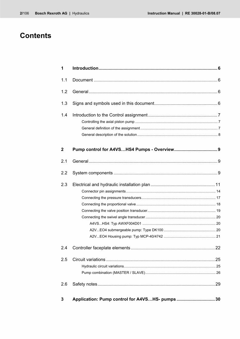
Solenoid connector wiring
to Controller to Controller
z2 z4 z6 z8z10
Fig. 10 Connecting the solenoids
A CECc 75301-803-A002FA-H3008-G cable connector according to DIN EN 175 301-803 and ISO 4400 is recommended for connecting the solenoids.
Solenoid a, cable connector color gray
Order separately under material number R901017010
Solenoid b, cable connector color black
Order separately under material number R901017011
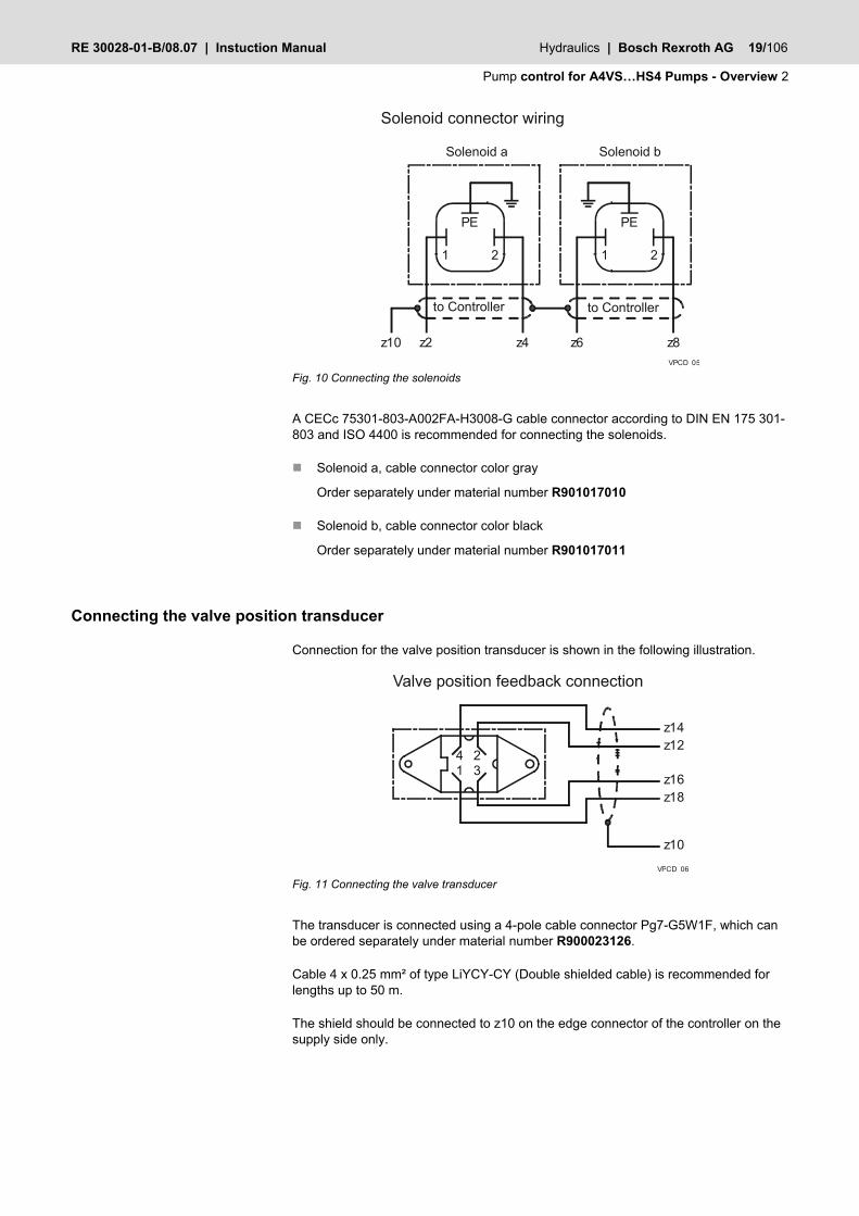
Connecting the valve position transducer
Connection for the valve position transducer is shown in the following illustration.
VPCD_06
34 21
Valve position feedback connection
z12z14
z16z18
z10
Fig. 11 Connecting the valve transducer
The transducer is connected using a 4-pole cable connector Pg7-G5W1F, which can be ordered separately under material number R900023126.
Cable 4 x 0.25 mm² of type LiYCY-CY (Double shielded cable) is recommended for lengths up to 50 m.
The shield should be connected to z10 on the edge connector of the controller on the supply side only.

20/106 Bosch Rexroth AG | Hydraulics Instuction Manual | RE 30028-01-B/08.07
2 Pump control for A4VS…HS4 Pumps - Overview
Connecting the swivel angle transducer
A4VS...HS4: Typ AWXF004D01
Connection for the swivel angle transducer is shown in the following illustration.
VPCD_07
34 21
f20f22
f24f26
z10
Fig. 12 Connecting the swivel angle transducer AWXF004D01
The transducer is connected using a 4-pole cable receptacle Pg7-G5W1F, which can be ordered separately under material number R900023126.
Housing pump:
Up to lengths of 50 m it is recommend to use cabling size 4 x 0.25mm of the type LiYCY-CY (24 AWG double shielded cable).
Submergeable pump:
For this type of pump the swivel angle transducer is located inside the oil. It is recom-mended to use cabeling type ÖLFLON® PTFE/FEP 4 x 0,75 mm² (Lapp Kabel).
When double shielded cable is used the outer shield can be terminated entering the control cabinet and the inner shield needs to be terminated at the controller card.
A2V...EO4 submergeable pump: Type DK100
Connection for the swivel angle transducer is shown in the following illustration.
f22f20
2134
5 f24f26
z10
Swivel angle feedback connection DK100
Fig. 13 Connecting the swivel angle transducer DK100
The transducer is connected using a 5-pole cable receptacle 130-9 IEC-22 DIN 45 321, which can be ordered separately.

RE 30028-01-B/08.07 | Instuction Manual Hydraulics | Bosch Rexroth AG 21/106
Pump control for A4VS…HS4 Pumps - Overview 2
Up to lengths of 50 m it ir recommend to use cabling size 4 x 0.25mm of the type LiYCY-CY (24 AWG double shielded cable).
When double shielded cable is used the outer shield can be terminated entering the control cabinet and the inner shield needs to be terminated at the controller card.
A2V...EO4 Housing pump: Typ MCP-40/4742
Connection for the swivel angle transducer is shown in the following illustration.
b32b28
21 3
45b12b28
b10
z10
Swivel angle feedback connection MCP-40/4742
Fig. 14 Connecting the swivel angle transducer MCP-40/4742
The connection is established by soldering connections.
Up to lengths of 50 m it is recommend to use cabling size 4 x 0.25mm of type LiYCY-CY (24 AWG double shielded cable).
When double shielded cable is used the outer shield can be terminated entering the control cabinet and the inner shield needs to be terminated at the controller card.

22/106 Bosch Rexroth AG | Hydraulics Instuction Manual | RE 30028-01-B/08.07
2 Pump control for A4VS…HS4 Pumps - Overview
2.4 Controller faceplate elements
Fig. 15 Faceplate elements
The LED indicates the status of the controller card.
OK “Ready”
„ Enable“ (d18) active
The buttons allow you to move around within the menu and access the individual parameters and error messages.
ENT
ESC
UP
DOWN
Status-LED
Buttons
RE 30028-01-B/08.07 | Instuction Manual Hydraulics | Bosch Rexroth AG 23/106
Pump control for A4VS…HS4 Pumps - Overview 2
ParameterCMD + ramp
0~ 15Angle CMD
Angle ramp
Pressure CMD
Pressure ramp
Power CMD
0~ 3Pressure control
P
Binary
Binary
Binary
Binary
Binary
4~ 7l [ms]
P
l [ms]8~ 11
P
l [ms]12~ 15
l [ms]
P
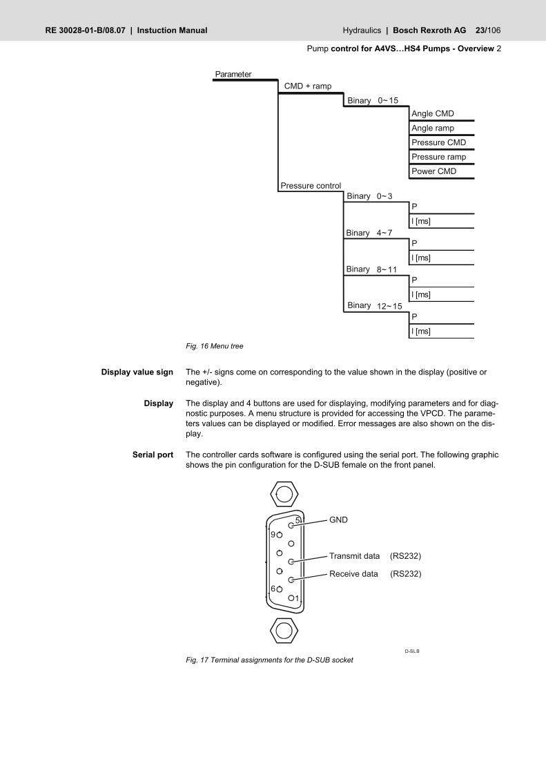
Fig. 16 Menu tree
The +/- signs come on corresponding to the value shown in the display (positive or negative).
The display and 4 buttons are used for displaying, modifying parameters and for diag-nostic purposes. A menu structure is provided for accessing the VPCD. The parame-ters values can be displayed or modified. Error messages are also shown on the dis-play.
The controller cards software is configured using the serial port. The following graphic shows the pin configuration for the D-SUB female on the front panel.
D-SUB
16
9
Receive data (RS232)
Transmit data (RS232)
GND5
Fig. 17 Terminal assignments for the D-SUB socket
Display value sign
Display
Serial port
24/106 Bosch Rexroth AG | Hydraulics Instuction Manual | RE 30028-01-B/08.07
2 Pump control for A4VS…HS4 Pumps - Overview
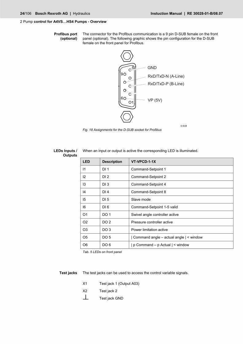
The connector for the Profibus communication is a 9 pin D-SUB female on the front panel (optional). The following graphic shows the pin configuration for the D-SUB female on the front panel for Profibus.
Fig. 18 Assignments for the D-SUB socket for Profibus
When an input or output is active the corresponding LED is illuminated.
LED Description VT-VPCD-1-1X
I1 DI 1 Command-Setpoint 1
I2 DI 2 Command-Setpoint 2
I3 DI 3 Command-Setpoint 4
I4 DI 4 Command-Setpoint 8
I5 DI 5 Slave mode
I6 DI 6 Command-Setpoint 1-5 valid
O1 DO 1 Swivel angle controller active
O2 DO 2 Pressure controller active
O3 DO 3 Power limitation active
O5 DO 5 | Command angle – actual angle | < window
O6 DO 6 | p Command – p Actual | < window
Tab. 5 LEDs on front panel
The test jacks can be used to access the control variable signals.
X1 Test jack 1 (Output A03)
X2 Test jack 2
Test jack GND
Profibus port (optional)
LEDs Inputs / Outputs
Test jacks

RE 30028-01-B/08.07 | Instuction Manual Hydraulics | Bosch Rexroth AG 25/106
Pump control for A4VS…HS4 Pumps - Overview 2
2.5 Circuit variations
The A4VS…HS4 axial piston unit can be operated in various circuit configurations, which means that adaptations to the axial piston unit are necessary for each variant.
The following circuit variations are possible:
Hydraulic circuit variations
– open loop – closed loop
Pump combination (MASTER / SLAVE)
– Circuit version for current-type pressure transducers – Circuit version for voltage-type pressure transducers
Hydraulic circuit variations
Hydraulic circuit variations refer to operation of the axial piston unit in open and in closed loop.
When operating the A4VSO...HS4 axial piston unit in open loop a sandwich plate is inserted between the A4VSO.. axial piston unit and the 4WRE6-2X/822 proportional valve. The corresponding sandwich plate is selected according to the rotation direc-tion of the pump
ab
ab
B A
PT
R5R6R7 R2R3R4U M2M1
BB1 MB
R(L)TK2K1MSS
US
SpP
Rkv
SpP
Rkv
A4VSO
Right hand rotation
Left hand rotation
Fig. 19 Connecting the swivel angle transducer
When operating the A4VSG...HS4 axial piston unit in closed loop a sandwich plate is inserted between the A4VSG.. axial piston unit and the 4WRE6-2X/822 proportional valve. The corresponding sandwich plate is selected according to the rotation direc-tion of the pump.
Open loop
Closed loop
26/106 Bosch Rexroth AG | Hydraulics Instuction Manual | RE 30028-01-B/08.07
2 Pump control for A4VS…HS4 Pumps - Overview
ab
ab
B A
PT
R5R6R7 R2R3R4 M2M1 R(L)TK2K3
US
Isolation valve (optional)
U
SpP
Rkv
SpP
Rkv
(+)
E
MAMB
B A
A4VSG
Right hand rotation
Left hand rotation
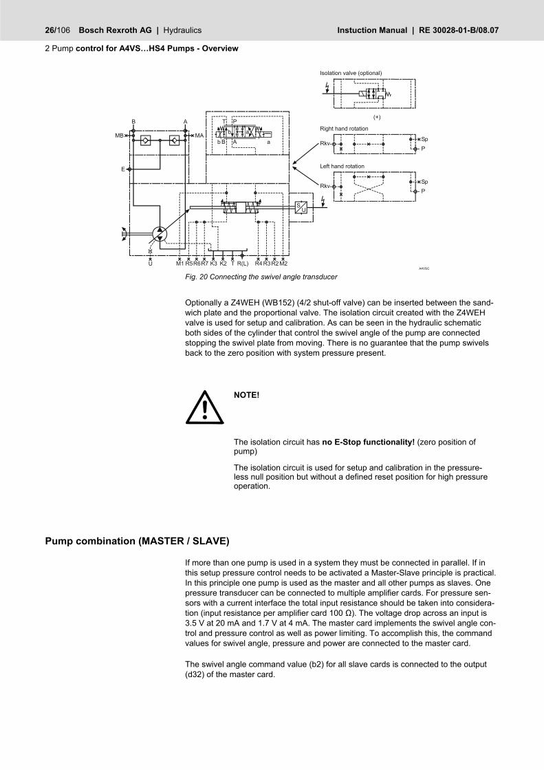
Fig. 20 Connecting the swivel angle transducer
Optionally a Z4WEH (WB152) (4/2 shut-off valve) can be inserted between the sand-wich plate and the proportional valve. The isolation circuit created with the Z4WEH valve is used for setup and calibration. As can be seen in the hydraulic schematic both sides of the cylinder that control the swivel angle of the pump are connected stopping the swivel plate from moving. There is no guarantee that the pump swivels back to the zero position with system pressure present.
NOTE!
The isolation circuit has no E-Stop functionality! (zero position of pump)
The isolation circuit is used for setup and calibration in the pressure-less null position but without a defined reset position for high pressure operation.
Pump combination (MASTER / SLAVE)
If more than one pump is used in a system they must be connected in parallel. If in this setup pressure control needs to be activated a Master-Slave principle is practical. In this principle one pump is used as the master and all other pumps as slaves. One pressure transducer can be connected to multiple amplifier cards. For pressure sen-sors with a current interface the total input resistance should be taken into considera-tion (input resistance per amplifier card 100 Ω). The voltage drop across an input is 3.5 V at 20 mA and 1.7 V at 4 mA. The master card implements the swivel angle con-trol and pressure control as well as power limiting. To accomplish this, the command values for swivel angle, pressure and power are connected to the master card.
The swivel angle command value (b2) for all slave cards is connected to the output (d32) of the master card.

RE 30028-01-B/08.07 | Instuction Manual Hydraulics | Bosch Rexroth AG 27/106
Pump control for A4VS…HS4 Pumps - Overview 2
The swivel angle command value reference (b4) for all slave cards must be connected to the output (b28) of the master card for Master-Slave operation.
In this case the pressure control only needs to be adjusted in the master card. The slave cards use the resulting command value of the master card when operating in swivel angle control.
A4VS_001
Pump 1 Pump 2 Pump n
Controller Controller Controller 1 2 n
i
pHM17+UB
Angle (cmd)
Pressure (cmd)
Power (cmd)
b22
b24
b4
b2
d10UB
b22
b24
b4
b2
d10UB
b22
b24
b16
b14
d10
b20
b18
f10
f8
d32
Connection diagram pressure transducer - Current interface
z32
b28
Fig. 21 Circuit version for current-type pressure sensors
A4VS_002
Pump 1 Pump 2 Pump n
Controller Controller 2 Controller n1
u
p
+UB
Angle (cmd)
Pressure (cmd)
Power (cmd)
b4
b2
d10UB
b4
b2
d10UB
b22
b24
b16
b14
d10
b20
b18
f10f8
d32
Connection diagram pressure transducer - Voltage interface
b28
HM17
Fig. 22 Circuit version for voltage-type pressure sensors

28/106 Bosch Rexroth AG | Hydraulics Instuction Manual | RE 30028-01-B/08.07
2 Pump control for A4VS…HS4 Pumps - Overview
It is also possible to realize a Master/Slave system via a fieldbus (Profibus / CANopen / DeviceNet). The parameters will be transmitted then via the bus and not via analog in-/outputs. You can see an example of such a system in the following picture. More information you will find in chapter “3.4 Bus Configuration”.
There are also combinations of analog inputs and bus communication possible.
Fig. 23 Fieldbus connection

RE 30028-01-B/08.07 | Instuction Manual Hydraulics | Bosch Rexroth AG 29/106
Pump control for A4VS…HS4 Pumps - Overview 2
2.6 Safety notes
NOTE!
The isolation circuit has no E-Stop functionality! (zero position of pump)
The isolation circuit is used for setup and calibration in the pressure less null position but without a defined reset position for high pressure operation.

30/106 Bosch Rexroth AG | Hydraulics Instuction Manual | RE 30028-01-B/08.07
3 Application: Pump control for A4VS…HS- pumps
3 Application: Pump control for A4VS…HS- pumps
3.1 Structured list for proceeding with start-up
The BODAC Software
Data interchange between BODCA software and the controller card VT-VPCD
Opening or creating Parameters
Save the working state
Configure inputs
Swivel Angle Command Pressure Command Power Command Actual pressure B Actual pressure A Res. Swivel Angle Command
Configure Profile
Command generation Configuration 1 Pressure Control Motion Data Faults Test jacks
Valve position transducer
Pump position transducer
Define Control parameters
Save parameters
Check Process settings
Test jacks Motion Data Status
Start the Application
Using software for start-up
Configure inputs
Define structure
Set null points
Enter parameters
Save the working state
Process settings
Starting the application
RE 30028-01-B/08.07 | Instuction Manual Hydraulics | Bosch Rexroth AG 31/106
Application: Pump control for A4VS…HS- pumps 3
3.2 Configure application sequence
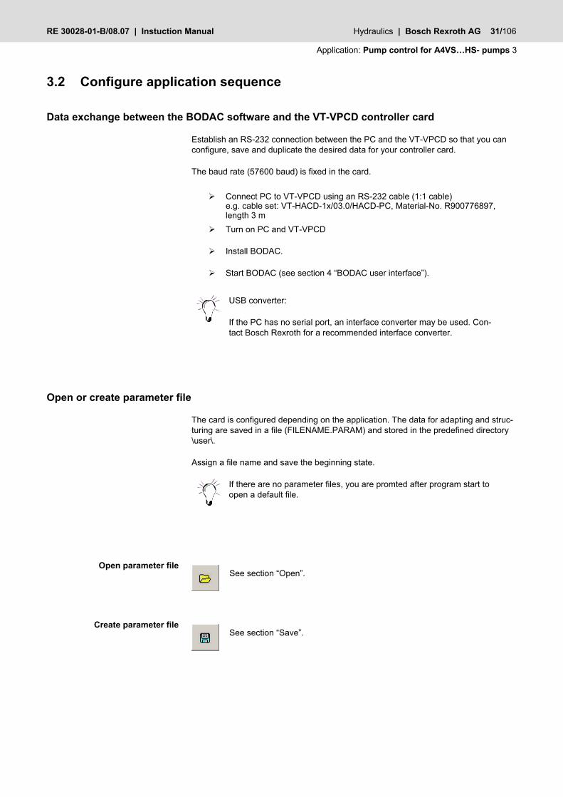
Data exchange between the BODAC software and the VT-VPCD controller card
Establish an RS-232 connection between the PC and the VT-VPCD so that you can configure, save and duplicate the desired data for your controller card.
The baud rate (57600 baud) is fixed in the card.
Connect PC to VT-VPCD using an RS-232 cable (1:1 cable) e.g. cable set: VT-HACD-1x/03.0/HACD-PC, Material-No. R900776897, length 3 m
Turn on PC and VT-VPCD
Install BODAC.
Start BODAC (see section 4 “BODAC user interface”).
USB converter:
If the PC has no serial port, an interface converter may be used. Con-tact Bosch Rexroth for a recommended interface converter.
Open or create parameter file
The card is configured depending on the application. The data for adapting and struc-turing are saved in a file (FILENAME.PARAM) and stored in the predefined directory \user\.
Assign a file name and save the beginning state.
If there are no parameter files, you are promted after program start to open a default file.
See section “Open”.
See section “Save”.
Open parameter file
Create parameter file

32/106 Bosch Rexroth AG | Hydraulics Instuction Manual | RE 30028-01-B/08.07
3 Application: Pump control for A4VS…HS- pumps
3.3 Configure inputs
The “Analog I/O” menu is where you configure the analog inputs on the controller card for your application.
Clicking on the preceding icon, which is a component of the toolbar, also opens the “Analog I/O” window. A list of existing shortcuts for the toolbar can be found in Section 4.2 “BODAC Toolbar”.
Fig. 24 “Analog I/O" window
The File menu in the “Analog I/O” window corresponds to the BODAC main window “File menu”.
Contains commands for reading, writing and modifying parameters.
Takes you directly to help for the current topic, or to the contents page of the BODAC windows help.
NOTE!
Note that set external command values are added to the internal command values of the profiles. If the external command value is turned off, only the parameterized internal set point always remains as the input for the controller.
Swivel angle command value
Here you define the swivel angle command value (external command value).
Assignments are made with the mouse button. Clicking on the “Type" entry field opens a selection field containing the following:
Analog I/O - File menu
Analog I/O - Controller menu
Analog I/O - Help menu
Type

RE 30028-01-B/08.07 | Instuction Manual Hydraulics | Bosch Rexroth AG 33/106
Application: Pump control for A4VS…HS- pumps 3
+/-10 V
The expected input signal varies in a range of (–10 V) to (+10 V).
4~20 mA
The current level of the input signal varies between (4 mA) and (20 mA).
Pressure command value
Here you define the pressure command value (external command value).
Assignments are made with the mouse button. Clicking on the “Type" entry field opens a selection field containing the following:
0~10 V
An input signal of from (0 V) to (+10 V) is expected
4~20 mA
The current level of the input signal varies between (4 mA) and (20 mA).
Power command value
Here you define the power command value (external command value).
Assignments are made with the mouse button. Clicking on the “Type" entry field opens a selection field containing the following:
0~10 V
An input signal of from (0 V) to (+10 V) is expected.
Actual pressure B
Here you define the actual pressure value on port “B” of the pump (see section 2.5 "Hydraulic Circuit Variations" Fig. 10 and Fig. 11).
Assignments are made with the mouse button. Clicking on the “Type" entry field opens a selection field containing the following:
0~10 V
An input signal of from (0 V) to (+10 V) is expected.
4~20 mA
The current level of the input signal varies between (4 mA) and (20 mA).
Which input signal you select depends on which pressure sensor is connected.
Type
Type
Type

34/106 Bosch Rexroth AG | Hydraulics Instuction Manual | RE 30028-01-B/08.07
3 Application: Pump control for A4VS…HS- pumps
Actual pressure A
Here you define the actual pressure value on port “A” of the pump (see section 2.5 "Hydraulic Circuit Variations" Fig. 10 and Fig. 11).
Assignments are made with the mouse button. Clicking on the “Type" entry field opens a selection field containing the following:
0~10 V
An input signal of from (0 V) to (+10 V) is expected.
4~20 mA
The current level of the input signal varies between (4 mA) and (20 mA).
Which input signal you select depends on which pressure sensor is connected.
When using just one pressure sensor (Actual pressure B), the error message from the second pressure sensor (Actual pressure A) must always be turned off. See section 3.4 “Errors”.
res. Swivel angle command value
Here you define the resulting swivel angle command value.
The output signal cannot be changed.
+/-10 V
The expected input signal varies in a range of (–10 V) to (+10 V).
MCP-40/4742 (Potentiometer-A2V)
Here you define the swivel angle actual value when using a ring potentiometer for swivel angle feedback (for A2-housing pumps only).
0~10 V
An input signal of from (0 V) to (+10 V) is expected.
Adjust input elements
Adjust the input elements as follows:
Use the right mouse button to assign an entry from the selection fields to the parameters.
Type
Type

RE 30028-01-B/08.07 | Instuction Manual Hydraulics | Bosch Rexroth AG 35/106
Application: Pump control for A4VS…HS- pumps 3
The external command values and actual values are selected. The logical links are defined.
This concludes the “Analog I/O” configuration.
3.4 Configure profiles
Command value configuration
For stable operation of the control action, a stable command value input is critical. Therefore, after the command value has been generated the signal is further config-ured by the Ramps before it is passed along to the controller as a command signal.
“Ramp” is provided for set point configuration. The entered ramp time always refers in the case of the swivel angle to a 100% command value jump, i.e., a command value change from 0 to 50% is reached in half the set ramp time.
In the case of the pressure command value, the normalization of the ramp refers to the pressure command value "Max. Unit" in the “Analog I/O” window.
Ramps and S-ramps are only necessary when parameterizing the angle (swivel angle) and the pressure.
In this window you parameterize the digital command values of swivel angle, pressure and power as well as the associated ramps.
Clicking on the preceding icon, which is a component of the toolbar, also opens the “Command values” window. A list of existing shortcuts for the toolbar can be found in Section 4.2 “BODAC Toolbar”.
Ramp
Command values

36/106 Bosch Rexroth AG | Hydraulics Instuction Manual | RE 30028-01-B/08.07
3 Application: Pump control for A4VS…HS- pumps
Fig. 25 “Command values” window
The File menu in the “Command values” window corresponds to the BODAC main window “File menu”.
Contains commands for reading, writing and modifying parameters.
Takes you directly to help for the current topic, or to the contents page of the BODAC windows help.
In this window you can configure the following parameters:
Swivel angle command value (+/-100 %)
Ramp time for swivel angle (0.01 … 300 s)
Pressure command value (0 … 600 bar)
Ramp time for pressure command value (0.01 … 300 s)
Power command value (0 … 100 %)
Depending on the application a maximum of 16 different settings can be configured for the parameters described above.
Command values – File menu
Command values – Controller menu
Command values – Help menu
Digital command values

RE 30028-01-B/08.07 | Instuction Manual Hydraulics | Bosch Rexroth AG 37/106
Application: Pump control for A4VS…HS- pumps 3
Configuration of the P- and I-terms of the pressure control for the parameter sets specified here is done in the “Pressure control” window (see section “Pressure con-trol").
The corresponding value of the analog set point is added (with correct sign) to the selected digital set point.
For the controller to work properly the pressure and power command value must be > 0 %.
Analog command values are fed in through the corresponding differential inputs. Note the following:
Swivel angle command value +/-10V %
Pressure and power command value 0 ... +10V
The analog command values are configured in the “Analog I/O” window.
NOTE!
When using differential inputs both inputs must always be turned on or off at the same time. The command values should be switched only using contacts appro-priate for currents < 1 mA.
The power command value is given in % of the maximum power limit.
Pump maximum power calculation:
PM Motor power
n Speed
VG Displacement
pmax System pressure
ηmh Mechanical-hydraulic efficiency
mhbarPncmVP G
η×××
=−
000.600][][min][ max
13
%100
Calculating the relationships:
%100)(%100
×=×PPap M
Analog command values
Power command value calculation

38/106 Bosch Rexroth AG | Hydraulics Instuction Manual | RE 30028-01-B/08.07
3 Application: Pump control for A4VS…HS- pumps
Example:
PM = 100 kW n = 1500 rpm
VG = 250 cm³ pmax = 450 bar
ηmh = 1 (theoretical value)
P100% = 281,25 kW
(p*α)max = 35.5%
The digital input DI6 sets the binary word as valid. Only if this input is High the pat-terns for inputs DI1 to DI5 are accepted. The current state remains valid until there is a state change.
In the motion data screen inputs DI1 to DI5 are only updated if DI6 shows a High level.
The active block can be calculated according to the following:
state = 8*DI4 + 4*DI3 + 2*DI2 + 1*DI1
where DIx = 0 if input shows a Low level (0V)
DIx = 1 if input shows a High level (24V).
The following shows the relationships of the digital inputs in a truth table:
state DI4 DI3 DI2 DI1 Bustrigger
binary 8
binary 4
binary 2
binary 1
binary 32 byte hex
0 0 0 0 0 0..00000000000000001 0x00000001
1 0 0 0 1 0..00000000000000010 0x00000002
2 0 0 1 0 0..00000000000000100 0x00000004
3 0 0 1 1 0..00000000000001000 0x00000008
4 0 1 0 0 0.00000000000010000 0x00000010
5 0 1 0 1 0..00000000000100000 0x00000020
6 0 1 1 0 0..00000000001000000 0x00000040
7 0 1 1 1 0..00000000010000000 0x00000080
… ... ...
12 1 1 0 0 0..00001000000000000 0x00001000
13 1 1 0 1 0..00010000000000000 0x00002000
14 1 1 1 0 0..00100000000000000 0x00004000
15 1 1 1 1 0..01000000000000000 0x00008000
Tab. 1 Truth-table of discrete inputs
Binary enable

RE 30028-01-B/08.07 | Instuction Manual Hydraulics | Bosch Rexroth AG 39/106
Application: Pump control for A4VS…HS- pumps 3
The states are activated by the high-end controller (SPS / PLC) according to the table shown using the digital inputs or fieldbus trigger.
Configuration 1
In this window you configure the given conditions of the loop or application.
Clicking on the preceding icon, which is a component of the toolbar, also opens the “Configuration 1” window. A list of existing shortcuts for the toolbar can be found in Section 4.2 “BODAC Toolbar”.
Fig. 26 “Configuration 1” window
The File menu in the “Configuration 1” window corresponds to the BODAC main win-dow “File menu”.
Contains commands for reading, writing and modifying parameters.
Takes you directly to help for the current topic or to the contents page of the BODAC windows help.
This area is where you configure the pump used in the application.
Configuration 1 – File menu
Configuration 1 – Controller menu
Configuration 1 – Help menu
Pump configuration

40/106 Bosch Rexroth AG | Hydraulics Instuction Manual | RE 30028-01-B/08.07
3 Application: Pump control for A4VS…HS- pumps
Leakage oil correction
This field is used for turning leakage oil correction on and off. Leakage oil correc-tion increases the internal swivel angle command value as a function of actual pressure by a nominal size-specific amount.
min. Actual swivel angle = 0 %
This option limits the I-term of the pressure controller and must be turned on if the pump has a zero end stop.
Pump size:
Use this field to select pump type and nominal size.
Direction of rotation:
– A4VS...HS4 right: Pressure at connection B with clockwise rotation (Stan-dard pump)
– A4VS...HS4 left: Pressure at connection A with counter clockwise rotation – A2V...EO4 right: – A2V...EO4 left
Valve
– 4WRE6V...-2X/822: Pilot valve for pump type A4VS...HS4 – 4WRE10V...-2X: Pilot valve for pump type A2V...EO4
Angle sensor
– AWXF004D01: Swivel angle transducer for pump type A4VS...HS4 – MCP-40/4742: Swivel angle transducer for housing pump A2V...EO4 – 0~10V: customer designed Swivel angle transducer
The digital outputs DO5 and DO6 are set using the serial interface by changing the values.
|Target swivel angle – Actual swivel angle|
The possible values for digital output DO5 are in a range from 0 to 200 %.
|Target pressure – Actual pressure|
The possible values for digital output DO6 are in a range from 0 to 600 bar.
Set null points for valve and pump position transducers
This area is where you set the offset for the “Valve” and “Pump” transducers. The offset is configured using the window as shown in Fig. 22 and the range is from (-100) to (+100).
Fig. 27 Configuring of the offsets in the “Configuration 1” window.
The pump offset needs to be set to 0 V if the enable is low and pilot oil is available. First check the swivel indicator of the pump to verify whether it is actually in the zero
Configuration dig. outputs
Configuration offset
Pump offset

RE 30028-01-B/08.07 | Instuction Manual Hydraulics | Bosch Rexroth AG 41/106
Application: Pump control for A4VS…HS- pumps 3
position. Change the value of the offset until the displayed value of the swivel angel is as close as possible to the actual angle value.
NOTE!
Check the offsets and readjust them as necessary whenever replacing the pump or control electronics.
The valve offset must be set after the enable is high:
Constant swivel angle input: Angle nom > 0 %
Change the “Valve offset” value until the angle error = 0 %
NOTE!
If, after the enable is raised the control valve or the pump demonstrate undefined movements, the following causes are possible
Hydraulic system insufficiently bled
No power command value given
No pressure command value given
If at a swivel angle input of +100 % (-100 %) the actual value deviates from the com-mand value (e.g. α nom = +100 % and α act = +90 % or at α nom = +100 % the pump does not reach the full displacement or a downstream cylinder or hydro motor does not reach its max. speed), the sensitivity of the pump transducer will have to be read-justed: Change the value “LVDT pump sens.” until the actual angle value corresponds to 100 %.
The pressure command value should correspond to the maximum pressure so that the pressure control remains inactive. The load valve must be fully open. When turning on the pump drive motor the general start-up requirements (in particular the direction of rotation of the electric motor) must be observed. The hydraulic fluid must be at operating temperature during start-up.
NOTE!
Enable of the control and thereby of the end stages is accomplished by a LOW-HIGH edge on the enable input (d18). After enabling the "OK" LED must come on and the output (d22) must go to High.
Valve offset
Recommended setting
Enable of the control

42/106 Bosch Rexroth AG | Hydraulics Instuction Manual | RE 30028-01-B/08.07
3 Application: Pump control for A4VS…HS- pumps
Pressure controller
In this screen you can configure the pressure controller parameters: The pressure controller is configured as a PI controller with a correction algorithm of the I sum.
Clicking on the preceding icon, which is a component of the toolbar, also opens the “Pressure controller” window. A list of existing shortcuts for the toolbar can be found in Section 4.2 “BODAC Toolbar”.
Fig. 28 “Pressure controller” window
The File menu in the “Pressure controller” window corresponds to the BODAC main window “File menu”.
The Controller menu contains commands for reading, writing and modifying parame-ters.
The Help menu takes you directly to the help for the current topic, or to the contents page of the BODAC windows help.
When switching from swivel angle control to pressure control, the I-part of the pres-sure controller must be quickly corrected to avoid or reduce pressure overshoots. When switching from pressure control to swivel angle control, especially when there is a small difference between pressure command value and pressure actual value and low P-gain, the I-sum (resulting integrator part of the controller) must also be cor-rected in order to ensure rapid rotation of the pump swash plate.
Correction is accomplished by using the parameter “I-pressure window”, which deter-mines the I correction. Within the pressure window (|Target – Actual| ≤pressure win-dow) the pressure controller operates like a normal PI controller with the set control parameters. If the control difference leaves the I-pressure window, the integrator por-tion of the PI controller uses a nearly quadratic function for correction (See figure 25).
Pressure controller – File menu
Pressure controller – Controller menu
Pressure controller – Help menu
RE 30028-01-B/08.07 | Instuction Manual Hydraulics | Bosch Rexroth AG 43/106
Application: Pump control for A4VS…HS- pumps 3
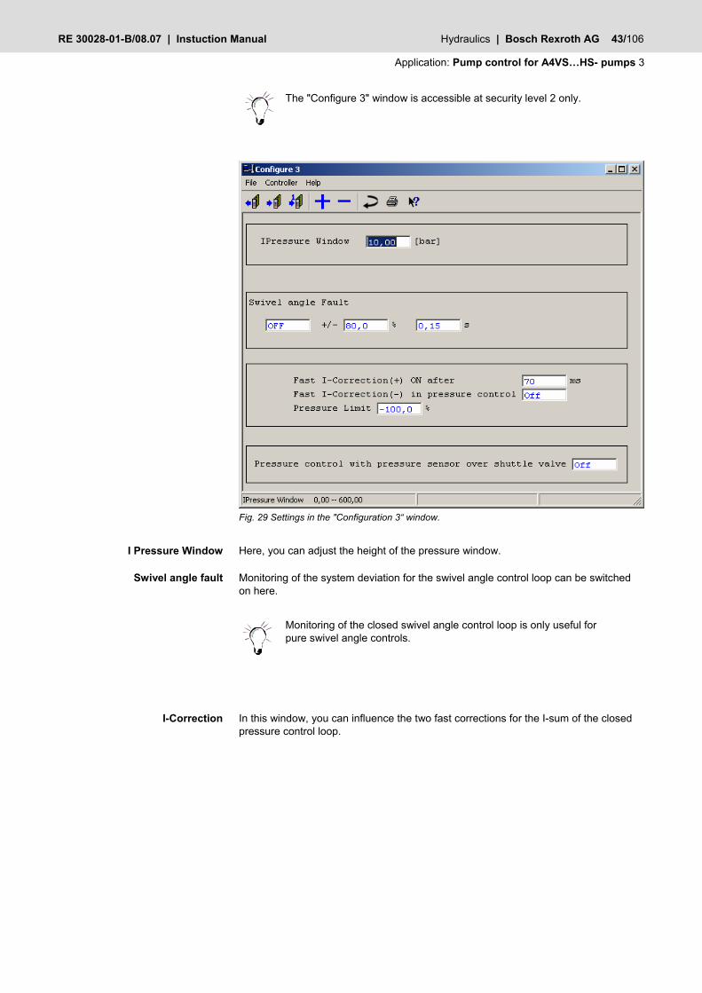
The "Configure 3" window is accessible at security level 2 only.
Fig. 29 Settings in the "Configuration 3“ window.
Here, you can adjust the height of the pressure window.
Monitoring of the system deviation for the swivel angle control loop can be switched on here.
Monitoring of the closed swivel angle control loop is only useful for pure swivel angle controls.
In this window, you can influence the two fast corrections for the I-sum of the closed pressure control loop.
I Pressure Window
Swivel angle fault
I-Correction
44/106 Bosch Rexroth AG | Hydraulics Instuction Manual | RE 30028-01-B/08.07
3 Application: Pump control for A4VS…HS- pumps
t
t
0+ Pressure window
Pressure window
Controller error| p - pcomm act |
-
I-Result
I I- -Correction Correction Fig. 30 Characteristic curve
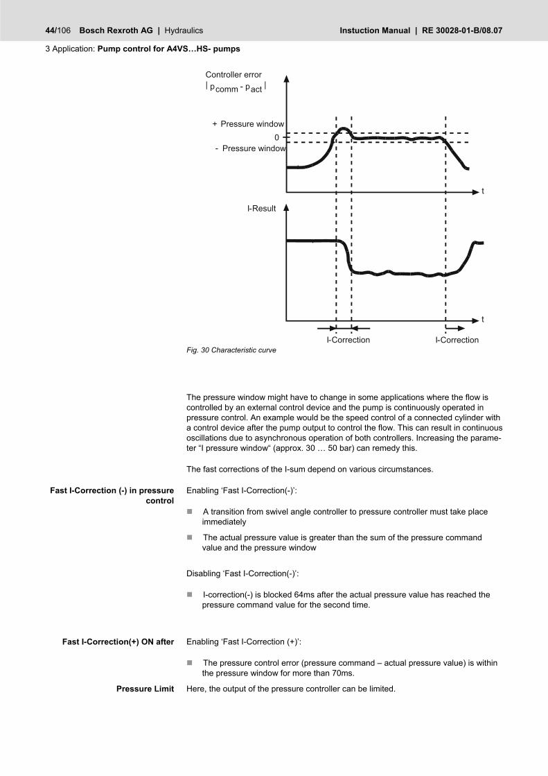
The pressure window might have to change in some applications where the flow is controlled by an external control device and the pump is continuously operated in pressure control. An example would be the speed control of a connected cylinder with a control device after the pump output to control the flow. This can result in continuous oscillations due to asynchronous operation of both controllers. Increasing the parame-ter “I pressure window“ (approx. 30 … 50 bar) can remedy this.
The fast corrections of the I-sum depend on various circumstances.
Enabling ‘Fast I-Correction(-)’:
A transition from swivel angle controller to pressure controller must take place immediately
The actual pressure value is greater than the sum of the pressure command value and the pressure window
Disabling ‘Fast I-Correction(-)’:
I-correction(-) is blocked 64ms after the actual pressure value has reached the pressure command value for the second time.
Enabling ‘Fast I-Correction (+)’:
The pressure control error (pressure command – actual pressure value) is within the pressure window for more than 70ms.
Here, the output of the pressure controller can be limited.
Fast I-Correction (-) in pressure control
Fast I-Correction(+) ON after
Pressure Limit

RE 30028-01-B/08.07 | Instuction Manual Hydraulics | Bosch Rexroth AG 45/106
Application: Pump control for A4VS…HS- pumps 3
An additional logic operation adjusts the I-term correspondingly when the control error is greater than 10 bar. To make sure the adjustment works properly, the pressure command value should be at least 10 bar bigger than the minimum back pressure.
Usually, two pressure sensors should be used for a two-sided closed-loop pressure control. The active pressure side is then determined on the basis of the maximum of the two pressure sensors. If the switch is set to ON, the active pressure side is determined on the basis of the actual swivel angle value. The actual pressure value must then be measured via a shuttle valve and fed to the port of pressure cell B.
In conjunction with pumps swiveling to both sides, the use of a pressure sensor can result in positive feedback.
Enhanced pressure controller
In this screen you can configure the pressure controller parameters: The pressure controller is configured as a PI controller with a correction algorithm of the I-sum. You can also configure the p-part and the I-part over the screen „pressure controller“.
Clicking on the preceding icon, which is a component of the toolbar, also opens the “Pressure controller” window. A list of existing shortcuts for the toolbar can be found in Section 4.2 “BODAC Toolbar”.
Pressure control with shuttle valve

46/106 Bosch Rexroth AG | Hydraulics Instuction Manual | RE 30028-01-B/08.07
3 Application: Pump control for A4VS…HS- pumps
Fig. 31 Enhanced “Pressure controller” window “
The File menu in the “Pressure controller” window corresponds to the BODAC main window “File menu”.
The Controller menu contains commands for reading, writing and modifying parame-ters.
The Help menu takes you directly to the help for the current topic, or to the contents page of the BODAC windows help.
The controller structure is illustrated in the figure below.
Pressure controller – File menu
Pressure controller – Controller menu
Pressure controller – Help menu

RE 30028-01-B/08.07 | Instuction Manual Hydraulics | Bosch Rexroth AG 47/106
Application: Pump control for A4VS…HS- pumps 3
Command (CMD)
Act. Value
Pressure stroke
DT1(LFB)
DT1
P
I
- - +
+
T1
(LFB)
Fig. 32 Controller structure for the pressure controller
The parameter in the “P" field changes the proportional component of the controller. It causes a proportional change in the output variable. The parameter has no unit and indicates the gain of the control error.
The parameter in the “I" field changes the integral component of the controller. It causes a velocity change in the output signal proportional to the time integral of the input signal. A value of “0” deactivates the I-controller. The I-component is given in milliseconds and represents the time required by the controller to change the control action from 0 to 100% in the case of a maximum con-trol error.
The parameter in the "I on |CMD-LFB|<" field defines the threshold for the I-controller. If |CMD-LFB| is less than the threshold, the I-controller is active. Above the threshold the I-controller is set to zero.
The parameter in the "I on |CMD-LFB|>" field defines the threshold for the I-controller. If |CMD-LFB| is greater than the threshold, the I-controller is active. Below the thresh-old the I-controller is frozen.
0
Io
Loop error
n CMD - LFB <
Ion CMD - LFB >
Ion CMD - LFB <
Ion CMD - LFB >
regelung_I
I controller=0
I controller acvtive
I controller acvtive
I controller frozen
I controller=0
Fig. 33 Function of the fields I on |CMD-LFB|
P
I
I on |CMD-LFB|<
I on |CMD-LFB|>
48/106 Bosch Rexroth AG | Hydraulics Instuction Manual | RE 30028-01-B/08.07
3 Application: Pump control for A4VS…HS- pumps
The parameter in the „DT1“ field changes the differential component of the controller. It causes a differentiated response of the output variable corresponding to the change speed of the input signal. A value of “0” deactivates the D-controller. A value of “2” set the DT1 controller to fast reaction.
The parameter in the "Damping" field is used to change the D-component of the actual value. This is used for a holdback of the actual value. A value of “0” deactivates the DT1(LFB) controller. A value of “2” set the DT1(LFB) controller to fast reaction.
The parameter in the „T1 Lag“ field implements a low-pass filter. A value of “640” deactivates the low-pass.
The enhanced "pressure controller" window is accessible at security level 2 only. The controller parameters are independent from the security-levels.
DT1
DT1 (LFB)
T1 Lag

RE 30028-01-B/08.07 | Instuction Manual Hydraulics | Bosch Rexroth AG 49/106
Application: Pump control for A4VS…HS- pumps 3
Motion data
This window shows the links between the individual process variables and the current values as well as the signal states.
Clicking on the preceding icon, which is a component of the toolbar, also opens the “Process display” window. A list of existing shortcuts for the toolbar can be found in Section 4.2 “BODAC Toolbar”.
Fig. 34 “Motion Data” window
The File menu in the “Motion Data ” window corresponds to the BODAC main window “File menu”.
The Controller menu contains commands for reading, writing and modifying parame-ters.
The Help menu takes you directly to the help for the current topic, or to the contents page of the BODAC windows help.
Faults
In this window you specify which error messages for the control circuit you want to output and log.
Clicking on the preceding icon, which is a component of the toolbar, also opens the “Faults” window. A list of existing shortcuts for the tool-bar can be found in Section 4.2 “BODAC Toolbar”.
Motion Data - File menu
Motion Data - Controller menu
Motion Data - Help menu

50/106 Bosch Rexroth AG | Hydraulics Instuction Manual | RE 30028-01-B/08.07
3 Application: Pump control for A4VS…HS- pumps
Fig. 35 “Faults” window
The File menu in the “Faults” window corresponds to the BODAC main window “File menu”.
The Controller menu contains commands for reading, writing and modifying parame-ters.
The Help menu takes you directly to the help for the current topic, or to the contents page of the BODAC windows help.
The parameters for which fault messages are output are configured as follows:
Select the corresponding parameter.
Use the mouse button to assign an entry from the selection fields to the pa rameter
Fault is configured.
The parameters may have the following states:
OFF There is no fault monitoring.
STOP
When a fault occurs the control process is stopped, the solenoids are de-energized and the pump goes (rotates) to its preferred position.
The fault range of the individual parameters is described in the section "Configure inputs”.
Faults – File menu
Faults – Controller menu
Faults – Help menu
Fault configuration

RE 30028-01-B/08.07 | Instuction Manual Hydraulics | Bosch Rexroth AG 51/106
Application: Pump control for A4VS…HS- pumps 3
Test jacks
In this window you can configure the test jacks: You specify which control parameter is available on the test points.
Clicking on the preceding icon, which is a component of the toolbar, also opens the “Test points” window. A list of existing shortcuts for the toolbar can be found in Section 4.2 “BODAC Toolbar”.
Fig. 36 “Test jacks” window
The File menu in the “Test jacks” window corresponds to the BODAC main window “File menu”.
The Controller menu contains commands for reading, writing and modifying parame-ters.
The Help menu takes you directly to the help for the current topic, or to the contents page of the BODAC windows help.
Configuration 3
In this window you specify the units of the I term for the pressure controller. The win-dow is only visible on Level “2”.
Clicking on the preceding icon, which is a component of the toolbar, also opens the “Configuration 3” window. A list of existing shortcuts for the toolbar can be found in Section 4.2 “BODAC Toolbar”.
Test jacks - File menu
Test jacks - Controller menu
Test jacks - Help menu
52/106 Bosch Rexroth AG | Hydraulics Instuction Manual | RE 30028-01-B/08.07
3 Application: Pump control for A4VS…HS- pumps
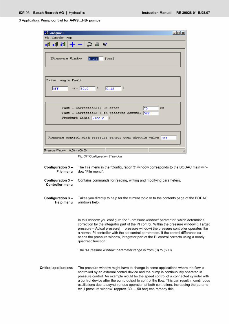
Fig. 37 “Configuration 3” window
The File menu in the “Configuration 3” window corresponds to the BODAC main win-dow “File menu”.
Contains commands for reading, writing and modifying parameters.
Takes you directly to help for the current topic or to the contents page of the BODAC windows help.
In this window you configure the "I-pressure window" parameter, which determines correction by the integrator part of the PI control. Within the pressure window (| Target pressure – Actual pressure| pressure window) the pressure controller operates like a normal PI controller with the set control parameters. If the control difference ex-ceeds the pressure window, integrator part of the PI control corrects using a nearly quadratic function.
The “I-Pressure window” parameter range is from (0) to (600).
The pressure window might have to change in some applications where the flow is controlled by an external control device and the pump is continuously operated in pressure control. An example would be the speed control of a connected cylinder with a control device after the pump output to control the flow. This can result in continuous oscillations due to asynchronous operation of both controllers. Increasing the parame-ter „I pressure window“ (approx. 30 … 50 bar) can remedy this.
Configuration 3 – File menu
Configuration 3 – Controller menu
Configuration 3 – Help menu
Critical applications

RE 30028-01-B/08.07 | Instuction Manual Hydraulics | Bosch Rexroth AG 53/106
Application: Pump control for A4VS…HS- pumps 3
The parameter “I-pressure window” is set to 10 bar by default. After entering the cor-responding value the data must be sent to the controller card.
Swivel angle error monitoring. If the control error is > 80 % for 0.15 s "OFF“ or "STOP” is executed.
Here, you can influence the two fast corrections for the I-sum of the closed pressure control loop.
t
t
0+ Pressure window
Pressure window
Controller error| p - pcomm act |
-
I-Result
I I- -Correction Correction Fig. 38 Characteristic curve
The pressure window might have to change in some applications where the flow is controlled by an external control device and the pump is continuously operated in pressure control. An example would be the speed control of a connected cylinder with a control device after the pump output to control the flow. This can result in continuous oscillations due to asynchronous operation of both controllers. Increasing the parame-ter „I pressure window“ (approx. 30 … 50 bar) can remedy this.
The fast corrections of the I-sum depend on various circumstances.
Enabling ‘Fast I-Correction(-)’:
A transition from swivel angle controller to pressure controller must take place immediately
The actual pressure value is greater than the sum of the pressure command value and the pressure window
Changes
Swivel angle error
I-Correction
Fast I-Correction (-) in pressure control

54/106 Bosch Rexroth AG | Hydraulics Instuction Manual | RE 30028-01-B/08.07
3 Application: Pump control for A4VS…HS- pumps
Disabling ‘Fast I-Correction(-)’:
I-correction(-) is blocked 64ms after the actual pressure value has reached the pressure command value for the second time.
Enabling ‘Fast I-Correction (+)’:
The pressure control error (pressure command – actual pressure value) is within the pressure window for more than 70ms.
Here, the output of the pressure controller can be limited.
An additional logic operation adjusts the I-term correspondingly when the control error is greater than 10 bar. To make sure the adjustment works properly, the pressure command value should be at least 10 bar bigger than the minimum back pressure.
Usually, two pressure sensors should be used for a two-sided closed-loop pressure control. The active pressure side is then determined on the basis of the maximum of the two pressure sensors. If the switch is set to ON, the active pressure side is determined on the basis of the actual swivel angle value. The actual pressure value must then be measured via a shuttle valve and fed to the port of pressure cell B.
In conjunction with pumps swiveling to both sides, the use of a pressure sensor can result in positive feedback.
Open Loop
In this window the user can configure a fixed pump control valve opening. The window is only visible on Level “2”.
Clicking on the preceding icon, which is a component of the toolbar in Level 2, also opens the “Open Loop” window. A list of existing short-cuts for the toolbar can be found in Section 4.2 “BODAC Toolbar”.
Fig. 39 “Open Loop” window
Fast I-Correction(+) ON after
Pressure Limit
Pressure control with shuttle valve

RE 30028-01-B/08.07 | Instuction Manual Hydraulics | Bosch Rexroth AG 55/106
Application: Pump control for A4VS…HS- pumps 3
The File menu in the “Open Loop” window corresponds to the BODAC main window “File menu”.
Contains commands for reading, writing and modifying parameters.
Takes you directly to help for the current topic, or to the contents page of the BODAC windows help.
In this window you can assign a fixed open loop variable to the control valve. Click on the Controller field.
Select „Controller inactive“.
Pressure control, Flow control and Power Limiting is switched off.
Enter the desired value in the „Valve stroke“ field.
To deselect the “Open Loop” function: Click on the Controller field.
Select „Controller active“.
Pressure control, Flow control and Power Limiting is switched on.
Enter a value of 0.0 in the „Valve stroke“ field.
Only the open loop variable is given to the valve. At this point neither the swivel angle controller nor the pressure controller or power limiting is active. With a open loop variable unequal to 0 the pump swivel plate rotates to ± 100 %.
The valve open loop variable becomes effective immediately after sending the value to the VPCD amplifier card.
Bus Configuration
In this window the user can choose which commands and trigger he wants to use.
Clicking on the preceding icon, which is a component of the toolbar, also opens the “Bus Configuration” window. A list of existing shortcuts for the toolbar can be found in Section 4.2 “BODAC Toolbar”.
Open Loop – File menu
Open Loop – Controller menu
Open Loop – Help menu
Configuration of the open loop variable

56/106 Bosch Rexroth AG | Hydraulics Instuction Manual | RE 30028-01-B/08.07
3 Application: Pump control for A4VS…HS- pumps
Fig. 40 “Bus Configuration” window
The File menu in the “Bus Configuration” window corresponds to the BODAC main window “File menu”.
Contains commands for reading, writing and modifying parameters.
Takes you directly to help for the current topic, or to the contents page of the BODAC windows help.
Choose Command:
Angle Command:
– b14/b16: Choose analog input for “Angle Command” – BUS: The parameter “Angle Command” will be transmitted via fieldbus to
the VPCD Pressure Command:
– b18/b20: Choose analog input for “Pressure Command”. – BUS: The parameter “Pressure Command” will be transmitted via fieldbus
to the VPCD Power Command:
– f8/f10: Choose analog input for “Power Command”. – BUS: The parameter “Power Command” will be transmitted via fieldbus to
the VPCD res. Angle Command:
– b2/b4: Choose analog input for “res. Angle Command”. – BUS: The parameter “res. Angle Command” will be transmitted via fieldbus
to the VPCD
Bus Configuration – File menu
Bus Configuration – Controller menu
Bus Configuration – Help menu

RE 30028-01-B/08.07 | Instuction Manual Hydraulics | Bosch Rexroth AG 57/106
Application: Pump control for A4VS…HS- pumps 3
Choose Activation:
Command Demand:
– CMD binary+MS binary: The switching between state is done by discrete inputs completely (normal and Master/Slave mode)
– CMD binay+MS BUS: The activating of state is done by discrete inputs in normal mode and via fieldbus in Master/Slave mode
– CMD BUS+MS binary: The activating of state is done by fieldbus in normal mode and for Master/Slave it is done with discrete inputs.
– CMD BUS+MS BUS: In normal and Master/Slave mode the activating is done by fieldbus.
Bus Trigger
This window show the actual state of the bus trigger. You can see here which bit is set in the bus trigger. Each state has it’s own bit. If there are problems with triggers via fieldbus, you can use this screen to be sure to send the correct data.
Clicking on the preceding icon, which is a component of the toolbar, also opens the “Bus Trigger” window. A list of existing shortcuts for the toolbar can be found in Section 4.2 “BODAC Toolbar”.
Fig. 41 “Bus Trigger” window
The File menu in the “Bus Trigger” window corresponds to the BODAC main window “File menu”.
Contains commands for reading, writing and modifying parameters.
Takes you directly to help for the current topic, or to the contents page of the BODAC windows help.
Bus Trigger – File menu
Bus Trigger – Controller menu
Bus Trigger – Help menu

58/106 Bosch Rexroth AG | Hydraulics Instuction Manual | RE 30028-01-B/08.07
3 Application: Pump control for A4VS…HS- pumps
Busmanager (Profibus, CANopen, DeviceNet)
In the "Bus manager" window you can adjust the parameters for bus communication and determine the parameters that are to be transmitted via the bus.
For the purpose of explanation, Profibus is used as an example.
Fig. 42 "Profibus" window
The File menu in the “Profibus” window corresponds to the BODAC main window “File menu”.
Contains commands for reading, writing and changing parameters.
Takes you directly to the current topic or to the contents page of the BODAC windows help.
Buttons are provided for frequently used functions. They are described in the section “Toolbar”.
In this window, bus parameters can be displayed and, where applicable, changed.
Here, you can determine the parameters to be transmitted from the controller card to the bus master (e.g. PLC).
Profibus – File menu
Profibus – Controller menu
Profibus – Help menu
Profibus – Toolbar
Transmit

RE 30028-01-B/08.07 | Instuction Manual Hydraulics | Bosch Rexroth AG 59/106
Application: Pump control for A4VS…HS- pumps 3
Fig. 43 Window "Profibus, Transmit HACD -> PLC"
The File menu in the "Profibus" window corresponds to the BODAC main window “File menu”.
Contains commands for reading, writing and changing parameters.
Takes you directly to the current topic or to the contents page of the BODAC windows help.
Buttons are provided for frequently used functions. They are described in the section “Toolbar”.
The selection field “Parameters" lists all parameters available in the HACD. A maxi-mum of 32 bytes can be transmitted via DP V0. These are subdivided into 4 buffers.
Parameters from the selection list are taken over for bus transmission.
Parameters are removed from the bus transmission.
If parameters that are available in several blocks are selected for bus transmission, the block number must be selected additionally.
Determines the parameters received by the controller card (HACD) from the bus mas-ter (e.g. PLC).
Profibus Transmit HACD->PLC– File menu
Profibus Transmit HACD->PLC– Controller menu
Profibus Transmit HACD->PLC– Help menu
Profibus Transmit HACD->PLC– Toolbar
Receive
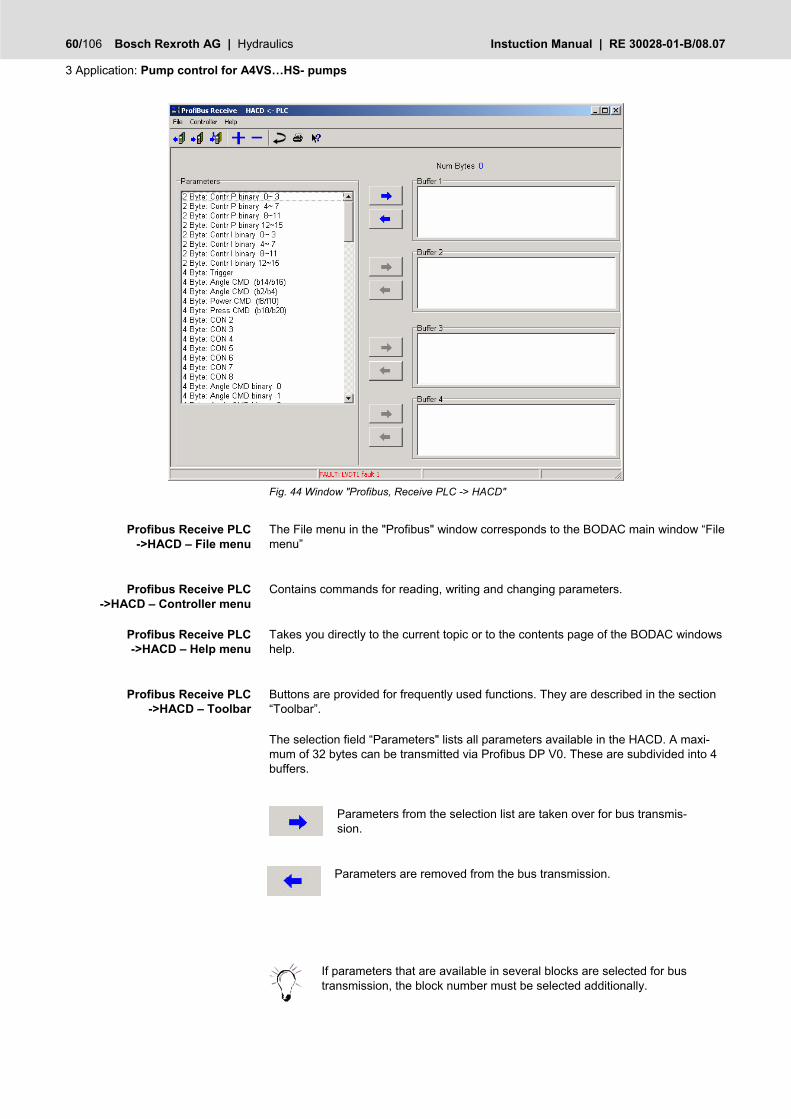
60/106 Bosch Rexroth AG | Hydraulics Instuction Manual | RE 30028-01-B/08.07
3 Application: Pump control for A4VS…HS- pumps
Fig. 44 Window "Profibus, Receive PLC -> HACD"
The File menu in the "Profibus" window corresponds to the BODAC main window “File menu”
Contains commands for reading, writing and changing parameters.
Takes you directly to the current topic or to the contents page of the BODAC windows help.
Buttons are provided for frequently used functions. They are described in the section “Toolbar”.
The selection field “Parameters" lists all parameters available in the HACD. A maxi-mum of 32 bytes can be transmitted via Profibus DP V0. These are subdivided into 4 buffers.
Parameters from the selection list are taken over for bus transmis-sion.
Parameters are removed from the bus transmission.
If parameters that are available in several blocks are selected for bus transmission, the block number must be selected additionally.
Profibus Receive PLC ->HACD – File menu
Profibus Receive PLC ->HACD – Controller menu
Profibus Receive PLC ->HACD – Help menu
Profibus Receive PLC ->HACD – Toolbar
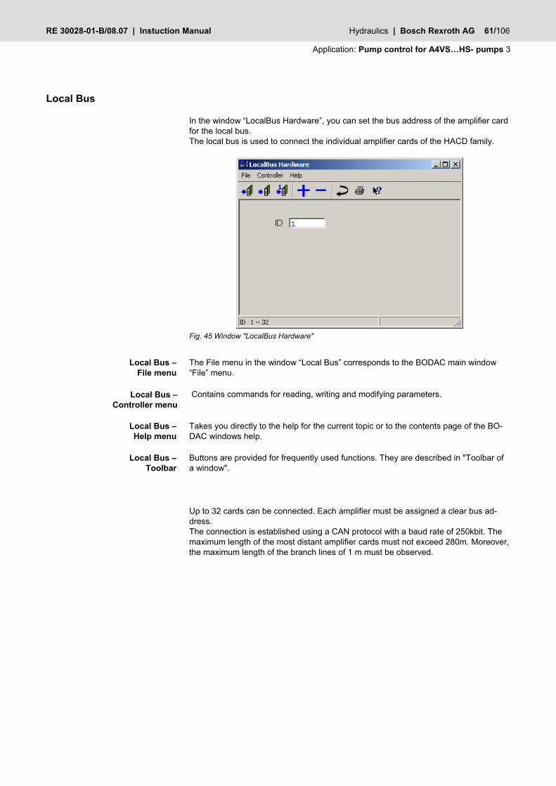
RE 30028-01-B/08.07 | Instuction Manual Hydraulics | Bosch Rexroth AG 61/106
Application: Pump control for A4VS…HS- pumps 3
Local Bus
In the window “LocalBus Hardware”, you can set the bus address of the amplifier card for the local bus. The local bus is used to connect the individual amplifier cards of the HACD family.
Fig. 45 Window "LocalBus Hardware"
The File menu in the window “Local Bus” corresponds to the BODAC main window “File” menu.
Contains commands for reading, writing and modifying parameters.
Takes you directly to the help for the current topic or to the contents page of the BO-DAC windows help.
Buttons are provided for frequently used functions. They are described in "Toolbar of a window".
Up to 32 cards can be connected. Each amplifier must be assigned a clear bus ad-dress. The connection is established using a CAN protocol with a baud rate of 250kbit. The maximum length of the most distant amplifier cards must not exceed 280m. Moreover, the maximum length of the branch lines of 1 m must be observed.
Local Bus – File menu
Local Bus – Controller menu
Local Bus – Help menu
Local Bus – Toolbar

62/106 Bosch Rexroth AG | Hydraulics Instuction Manual | RE 30028-01-B/08.07
3 Application: Pump control for A4VS…HS- pumps
Fig. 46 Schematic structure of “Local Bus“
Data is to be transmitted via a shielded twisted-pair cable.
Two bus terminating resistors of 120 Ohm are required.
3.5 Define controller parameters
The necessary loop settings for your application can be done in the „Pressure control-ler" window. The values entered affect the loop behavior.
Clicking on the preceding icon, which is a component of the toolbar, also opens the “Pressure controller” window. A list of existing shortcuts for the toolbar can be found in Section 4.2 “BODAC Toolbar”.

RE 30028-01-B/08.07 | Instuction Manual Hydraulics | Bosch Rexroth AG 63/106
Application: Pump control for A4VS…HS- pumps 3
Fig. 47 “Pressure controller” window
The File menu in the “Pressure controller” window corresponds to the BODAC main window “File menu”.
The Controller menu contains commands for reading, writing and modifying parame-ters.
The Help menu takes you directly to the help for the current topic, or to the contents page of the BODAC windows help.
Differences between VT12350-3x and VT-VPCD in the control pa-rameters:
VT12350-3x VT-VPCD
P 20 corresponds to
I 10 ms 100 ms
Parameterizing the pressure controller
Parameterization of the loop settings for the command values “Binary 0” to "Binary 3".
The parameter in the “P” entry field changes the proportional component of the con-troller. It affects a proportional change in the output variable corresponding to the input variable.
Pressure controller – File menu
Pressure controller – Controller menu
Pressure controller – Help menu
Control parameters binary 0 to 3
P

64/106 Bosch Rexroth AG | Hydraulics Instuction Manual | RE 30028-01-B/08.07
3 Application: Pump control for A4VS…HS- pumps
The parameter in the “I” entry field changes the integral term of the controller. It af-fects a rate of change of the output signal proportional to the time integral of the input signal.
Parameterization of the loop settings for the command values “Binary 4” to "Binary 7".
The parameter in the “P” entry field changes the proportional term of the controller. It affects a proportional change in the output variable corresponding to the input vari-able.
The parameter in the “I” entry field changes the integral term of the controller. It af-fects a rate of change of the output signal proportional to the time integral of the input signal.
Parameterization of the loop settings for the command values “Binary 8” to "Binary 11".
The parameter in the “P” entry field changes the proportional term of the controller. It affects a proportional change in the output variable corresponding to the input vari-able.
The parameter in the “I” entry field changes the integral term of the controller. It af-fects a rate of change of the output signal proportional to the time integral of the input signal.
Parameterization of the loop settings for the command values “Binary 12” to "Binary 15".
The parameter in the “P” entry field changes the proportional term of the controller. It affects a proportional change in the output variable corresponding to the input vari-able.
The parameter in the “I” entry field changes the integral term of the controller. It af-fects a rate of change of the output signal proportional to the time integral of the input signal.
Enter the corresponding values in the entry fields.
This concludes parameterizing of the pressure controller.
I
Control parameters binary 4 to 7
P
I
Control parameters binary 8 to 11
P
I
Control parameters Binary 12 to 15
P
I
Enter parameters
RE 30028-01-B/08.07 | Instuction Manual Hydraulics | Bosch Rexroth AG 65/106
Application: Pump control for A4VS…HS- pumps 3
3.6 Save parameter file
All necessary functions have been parameterized.
Save the data in a parameter file (FILENAME.PARAM). The parameter file is stored in the predetermined directory \user\.
See section “Save”.
3.7 Check Application settings
If enable is activated and there are no errors, the user can get a quick overview of”
the current parameters (“Configuration 1” and “Pressure controller” windows)
the current controller structure (“Motion Data” window)
the signals present (“Motion Data” window)
the status of your controller card („Card information“ window)
If the “binary valid” signal is at “OFF”, then “binary” is always set to “Zero”.
Test jacks
For diagnostic purposes you can assign signals to the "X1" and “X2” test jacks on the front panel of the controller card.
Clicking on the preceding icon, which is a component of the toolbar, also opens the “Test points” window. A list of existing shortcuts for the toolbar can be found in Section 4.2 “BODAC Toolbar”.
See Section “Test jacks”.
Motion Data
You can view the entire signal sequence of your application in real-time.

66/106 Bosch Rexroth AG | Hydraulics Instuction Manual | RE 30028-01-B/08.07
3 Application: Pump control for A4VS…HS- pumps
Clicking on the preceding icon, which is a component of the toolbar, also opens the “Process display” window. A list of existing shortcuts for the toolbar can be found in Section 4.2 “BODAC Toolbar”.
See section “Motion Data”.
Status overview
The “Status overview” window provides an overview of the current faults that are de-tected while the controller card is operating.
Clicking on the preceding icon, which is a component of the toolbar, also opens the “Status” window. A list of existing shortcuts for the toolbar can be found in Section 4.2 “BODAC Toolbar”.
See section “Status overview”.
3.8 Start application
The application is started with digital input “D18”. This input corresponds with the enable function of the controller card.
See also Fig. 3 in section 2.
Starting up
RE 30028-01-B/08.07 | Instuction Manual Hydraulics | Bosch Rexroth AG 67/106
User interface BODAC - General 4
4 User interface BODAC - General
4.1 Software tool and data handling
The BODAC Software
BODAC is a software tool for start-up. It must be installed on the PC or laptop you are using for the initial startup.
BODAC stands for:
Bosch Rexroth Operator interface for Digital Axis Controller for in- and output configu-ration, controller structure configuration, parameterization, motion data and diagnos-tics.
This software tool can be downloaded from the Internet at http://www.boschrexroth.com/hacd.
Data exchange between BODAC and the VPCD
Establish a connection between the PC and the VT-VPCD so that you can set, save and duplicate the desired data.
The connection is based on RS232. A fixed baud rate is set in the card (57600 baud).
Use an RS232 cable (1:1 cable) to connect the PC to the VPCD.
Turn on PC and VPCD.
Install BODAC.
Start BODAC (see document RE 30028-B)
BODAC automatically uploads the parameter set from the VPCD.
If BODAC does not upload automatically, no connection was made. In this case check the “Configuration of the serial interface”, the serial connection and the supply voltage.
Create file
It is recommended that the parameter set be saved in a file. This allows you to restore the current status of the VPCD at any time.
Assign a file name and save the initial parameter settings.

68/106 Bosch Rexroth AG | Hydraulics Instuction Manual | RE 30028-01-B/08.07
4 User interface BODAC - General
Save the current status
This allows you to easily store all parameters and structure specifications during startup. If your work is interrupted, you can resume later without any loss of data.
To finalize your work, save the data also in the permanent memory (flash) of the VPCD card.
See also: “Save”.
See also: “Set parameters to memory”
4.2 Main Menu
These include: The title bar
The menu bar
The toolbar
The status bar
Fig. 48 BODAC main menu
RE 30028-01-B/08.07 | Instuction Manual Hydraulics | Bosch Rexroth AG 69/106
User interface BODAC - General 4
Title bar
The title bar contains the name of the program/window and several standard Windows buttons. Information about the standard Windows buttons can be found in your Win-dows online help.
Menu bar
The menu bar lists all the menus and commands available in BODAC.
The following menus are available: File menu
Controller menu
View menu
Configuration menu
Options menu
Application Window menu
Windows menu
Help menu
BODAC toolbar
The toolbar contains buttons with symbols (icons) execute the most commonly used functions, invoke commands or open windows when clicked on with the mouse.
Following is a list of the available functions:
Generates the “Offline” command, which breaks the connection to the controller card. The symbol is only visible if there is an active connec-tion to the card. Generates the “Connect” command. The symbol is only visible if there is no active connection to the card.
Opens the “Open” window, where you can select stored BODAC data files.
Opens the “Save file as” window, in which you can save your entries.
Opens the "Analog in-/outputs“ (“Analog I/O”) window.
Opens the "Status“ window.
The “Read parameters” command reads the data (parameter set) stored in the working memory of the VPCD and passes the set to the BODAC program.

70/106 Bosch Rexroth AG | Hydraulics Instuction Manual | RE 30028-01-B/08.07
4 User interface BODAC - General
The “Write parameters” command sends the current data (parameter set) from BODAC to the working memory of the VPCD.
The “Set parameters to memory” sends the VPCD parameter set from working memory to permanent memory.
Opens the "Language“ window.
Opens the "Print forms“ window.
Opens the "Command values“ window.
Opens the "Configuration 1“ window.
Opens the "Pressure controller“ window.
Opens the "Motion Data“ window.
Opens the "Faults“ window.
Opens the "Test jacks“ window.
Window toolbar
The Window toolbar contains buttons with symbols (icons) execute the most com-monly used functions, invoke commands or open windows when clicked on with the mouse.
Following is a list of the available functions:
see 4.2 “Read Parameters”
see 4.2 “Write Parameters”
Clicking on this symbol writes only the parameter value you have just changed to the card.
The “Set parameters to memory” sends the current data from BODAC to the memory chip of the controller card.
If you are in an entry field, you can click on the symbol “+” to increment the field contents. Simultaneously BODAC writes this parameter to the card.
Exception: Multiplot, see “Multiplot toolbar”

RE 30028-01-B/08.07 | Instuction Manual Hydraulics | Bosch Rexroth AG 71/106
User interface BODAC - General 4
If you are in an entry field, you can click on the "-" symbol to decre-ment the field contents. Simultaneously BODAC writes this parameter to the card.
Exception: Multiplot, see “Multiplot toolbar”
The Undo symbol in the toolbar nullifies the last entry.
Clicking on the oscilloscope symbol in the toolbar opens the BODAC window “Multiplot”.
To show signals in the Multiplot window, open the Motion Data window and click on the name of the desired signal. The name of the signal is highlighted in red to indicate that it is selected for display in the Mul-tiplot window. Then click on the oscilloscope symbol in the toolbar to open the Multiplot window. The signals you selected will be displayed.
You can also select more signals once the "Multiplot" window is opened.
A maximum of 8 signals can be selected.
For information on the Multiplot window, see section 3.3 “Multiplot”.
Clicking on the printer symbol in the toolbar opens the Windows sys-tem window “Print”.
The Help symbol in the toolbar generates a help pointer. Clicking with the help pointer on a parameter field opens the help for this parameter field. The Data Log symbol in the toolbar generates a file with the extension “.log” in which all motion data are stored.
Status bar
The status bar contains useful information about the active window. For example the main menu shows the current connection status.
Short cut list
You can also invoke important functions using the function keys on the keyboard. The function keys are defined as follows:
F1 Opens BODAC Help (see also “Help menu”)
F2 Reads the currently saved data in the controller card and sends them to the BODAC program. (see also “Read Parameters”)
F3 Sends the settings and entries you made to the card and overwrites the previously saved data in volatile memory. (see also “Write Parame-ters”)
F11 If you are in an entry field, you can press “F11” to increment the field contents. Simultaneously BODAC writes this parameter to the card.

72/106 Bosch Rexroth AG | Hydraulics Instuction Manual | RE 30028-01-B/08.07
4 User interface BODAC - General
F12 If you are in an entry field, you can press “F12” to decrement the field contents. Simultaneously BODAC writes this parameter to the card.
Page-down
If you are in the structure editor in the entry field block, you can use “Page down” to increment the field contents. This then opens the next higher block.
Page-up
If you are in the structure editor in the entry field block, you can use “Page up” to decrement the field contents. This then opens the next lower block.
Notes

RE 30028-01-B/08.07 | Instuction Manual Hydraulics | Bosch Rexroth AG 73/106
BODAC – Menu Description 5
5 BODAC – Menu Description
5.1 File menu
The “File” menu contains commands for administering and printing data.
Fig. 49 “File” menu
Open
Opens a window in which you can load the complete parameter structure that you previously created and saved in BODAC. The profile contains all the values and pa-rameters you specified and entered before saving in BODAC.
Clicking on the preceding icon, which is a component of the toolbar, also opens the window in which you can select the saved data files. A list of existing shortcuts for the toolbar can be found in Section 4.2 “BODAC Toolbar”.
Save
Opens a window in which you can save all the data you entered and specified while working with BODAC under a file name of your choice. This creates a file you can use to send the functionality of this card to additional cards. The file has a “.param” exten-sion.
Clicking on the preceding icon, which is a component of the toolbar, also opens the window in which you can save your entries. A list of existing shortcuts for the toolbar can be found in Section 4.2 “BODAC Toolbar”.
Save the complete parameter structure after installation is complete! When replacing a defective card you can transfer the existing parame-ter structure to the new card. This card is then immediately ready for use with all previously defined parameters and value settings. You can also send already defined parameter structures to comparable or simi-lar applications.

74/106 Bosch Rexroth AG | Hydraulics Instuction Manual | RE 30028-01-B/08.07
5 BODAC – Menu Description
Printer Setup
This menu point opens the standard Windows “Printer Setup" window. Information about setting up a printer can be found in your Windows online help.
This menu point first opens the “Print” window as shown in the following illustration.
Fig. 50 “Print” window
The window is divided into several columns. In the Print column you select the data sheet you want to print. If more than one data sheet is available for a form, select the number of data sheets to print under Options.
Clicking on the preceding icon, which is a component of the toolbar, also opens the “Print” window. A list of existing shortcuts for the toolbar can be found in Section 4.2 “BODAC Toolbar”.
Clicking on the “Print” button takes you to the standard “Print” window of Windows. Information about the Print window can be found in your Windows online help.
Quit
Closes all currently opened windows and quits the BODAC program.

RE 30028-01-B/08.07 | Instuction Manual Hydraulics | Bosch Rexroth AG 75/106
BODAC – Menu Description 5
5.2 Controller menu
The “Controller” menu contains commands for direct communication with the card. These commands are used to send or receive data to and from the card.
Fig. 51 “Controller” menu
Offline
Closes the connection to the card. The “Offline” command is only selectable if there is an active connection to the controller card.
Clicking on the preceding icon, which is a component of the toolbar, also generates the “Offline” command. The symbol is only visible if there is no currently active connection to the card. A list of existing shortcuts for the toolbar can be found in Section 4.2 “BODAC Toolbar”.
Connect
Opens the connection between BODAC and the HACD. The “Connect” command is only selectable if there is no active connection to the card.
Clicking on the preceding icon, which is a component of the toolbar, also generates the “Connect” command. The symbol is only visible if there is no currently active connection to the card. A list of existing shortcuts for the toolbar can be found in Section 4.2 “BODAC Toolbar”.

76/106 Bosch Rexroth AG | Hydraulics Instuction Manual | RE 30028-01-B/08.07
5 BODAC – Menu Description
Search Card
The command “Search Card” opens the window “Search Card”, searches for active cards on the local bus and lists them in a tabular form.
Fig. 52 Window “Search Cards“
Cards are searched for on the local bus.
Bodac connects to the selected card.
Bodac changes over to the offline mode and closes the connection with the active card.
The search for cards is interrupted, and Bodac maintains the connection with the active card.
In the first column “ID“ the bus address of the card is shown. The master bus address is not listed, but must differ from the bus addresses of other cards. The second column “Mat. Nr.“ includes the material number of the card and the ver-sion number of the configuration. (see “Card information“). The third column “Description“ shows the text presented on the display. This text can be changed in the window “Card information“.
Read parameters
The “Read parameters” command reads the data (parameter set) stored in the work-ing memory of the controller card and passes the set to the BODAC program.
Clicking on the preceding icon, which is a component of the toolbar, also reads out the data stored in the card and sends them to the BO-DAC program. A list of existing shortcuts for the toolbar can be found in Section 4.2 “BODAC Toolbar”.
Write Parameters
The “Write parameters” command sends the settings and entries you made to the controller card and overwrites the previously saved data in volatile memory.
Start Search
Connect
Offline
Cancel

RE 30028-01-B/08.07 | Instuction Manual Hydraulics | Bosch Rexroth AG 77/106
BODAC – Menu Description 5
NOTE!
The new data is available as long as the card has power. If the card is disconnected from its power source, the data will be lost.
To save data permanently on the controller card, read the section “Set parameters to memory”.
Clicking on the preceding icon, which is also a component of the tool-bar, also sends the settings and entries you made to the card and overwrites the previously saved data in volatile memory. A list of exist-ing shortcuts for the toolbar can be found in Section 4.2 “BODAC
Set parameters to memory
Sends the current data available in BODAC to the cards flash memory. This saves the data to the non-volatile memory of the card so it is still available after a power inter-ruption.
The preceding icon, which is a component of the toolbar, sends the current data from BODAC to the card non-volatile memory. A list of existing shortcuts for the toolbar can be found in Section 4.2 “BODAC Toolbar”.
Language
The “Language” menu point contains the following options: English
Deutsch
Clicking on the preceding icon, which is a component of the toolbar, opens a selection menu in which you can also select the language. A list of existing shortcuts for the toolbar can be found in Section 4.2 “BODAC Toolbar”.
Displays all the entries, windows, menus, etc. in English.
Displays all the entries, windows, menus, etc. in German.
NOTE!
The software language selection also affects the language version of your card.
The menu tree operated by the buttons on the front panel of your card is also switched over to the selected language.
The language selection is stored in the card.
English
Deutsch
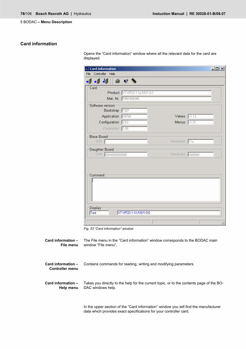
78/106 Bosch Rexroth AG | Hydraulics Instuction Manual | RE 30028-01-B/08.07
5 BODAC – Menu Description
Card information
Opens the “Card information” window where all the relevant data for the card are displayed.
Fig. 53 “Card information” window
The File menu in the “Card information” window corresponds to the BODAC main window “File menu”.
Contains commands for reading, writing and modifying parameters.
Takes you directly to the help for the current topic, or to the contents page of the BO-DAC windows help.
In the upper section of the “Card information” window you will find the manufacturer data which provides exact specifications for your controller card.
Card information – File menu
Card information – Controller menu
Card information – Help menu
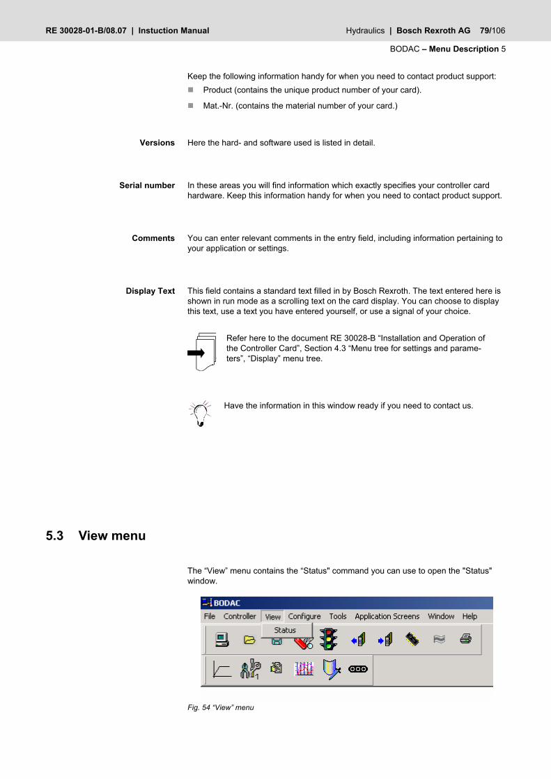
RE 30028-01-B/08.07 | Instuction Manual Hydraulics | Bosch Rexroth AG 79/106
BODAC – Menu Description 5
Keep the following information handy for when you need to contact product support: Product (contains the unique product number of your card).
Mat.-Nr. (contains the material number of your card.)
Here the hard- and software used is listed in detail.
In these areas you will find information which exactly specifies your controller card hardware. Keep this information handy for when you need to contact product support.
You can enter relevant comments in the entry field, including information pertaining to your application or settings.
This field contains a standard text filled in by Bosch Rexroth. The text entered here is shown in run mode as a scrolling text on the card display. You can choose to display this text, use a text you have entered yourself, or use a signal of your choice.
Refer here to the document RE 30028-B “Installation and Operation of the Controller Card”, Section 4.3 “Menu tree for settings and parame-ters”, “Display” menu tree.
Have the information in this window ready if you need to contact us.
5.3 View menu
The “View” menu contains the “Status" command you can use to open the "Status" window.
Fig. 54 “View” menu
Versions
Serial number
Comments
Display Text

80/106 Bosch Rexroth AG | Hydraulics Instuction Manual | RE 30028-01-B/08.07
5 BODAC – Menu Description
Status
This menu item opens the “Status” window, which provides an overview of the current faults which were detected while the controller card was operating.
Clicking on the preceding iconl, which is a component of the toolbar, also opens the “Status” window. A list of existing shortcuts for the toolbar can be found in Section 4.2 “BODAC Toolbar”.
Fig. 55 “Status” window
Remains green as long as no fault has been detected.
Remains yellow when a fault has been detected. If a signal you want to monitor is set to “Flag” in the “Faults” window, operation of the card is not interrupted. The fault is recognized, saved and processing continues.
Lights up red when a fault has been detected. The controller card stops the process. Set the monitored signal in the “Faults” window to “Stop”.
An error is indicated if the signal is outside the defined signal range. The signal range is determined in the analog in-/outputs configuration window.
A fault is indicated if there is a cable break or short circuit on the LVDT transducer for the proportional valve.
A fault is indicated if there is a cable break or short circuit on the LVDT transducer for the pump.
A fault is indicated if there is a short circuit on the proportional valve solenoid.
The checksum for the memory chip shows a deviation from the currently stored data in the chip.
OK
Fault
STOP
Angle command value Pressure command value
Power command value Actual pressure B Actual pressure A
LVDT1 fault 1 to 3
LVDT2 fault 1 to 3
Solenoid short circuit
Checksum flash
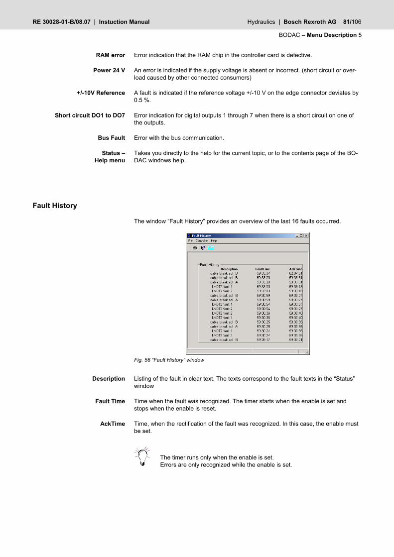
RE 30028-01-B/08.07 | Instuction Manual Hydraulics | Bosch Rexroth AG 81/106
BODAC – Menu Description 5
Error indication that the RAM chip in the controller card is defective.
An error is indicated if the supply voltage is absent or incorrect. (short circuit or over-load caused by other connected consumers)
A fault is indicated if the reference voltage +/-10 V on the edge connector deviates by 0.5 %.
Error indication for digital outputs 1 through 7 when there is a short circuit on one of the outputs.
Error with the bus communication.
Takes you directly to the help for the current topic, or to the contents page of the BO-DAC windows help.
Fault History
The window “Fault History” provides an overview of the last 16 faults occurred.
Fig. 56 “Fault History” window
Listing of the fault in clear text. The texts correspond to the fault texts in the “Status” window
Time when the fault was recognized. The timer starts when the enable is set and stops when the enable is reset.
Time, when the rectification of the fault was recognized. In this case, the enable must be set.
The timer runs only when the enable is set. Errors are only recognized while the enable is set.
RAM error
Power 24 V
+/-10V Reference
Short circuit DO1 to DO7
Bus Fault
Status – Help menu
Description
Fault Time
AckTime

82/106 Bosch Rexroth AG | Hydraulics Instuction Manual | RE 30028-01-B/08.07
5 BODAC – Menu Description
5.4 Configuration menu
The “Configuration” menu contains the “Analog I/O” command which you use to open the window for configuring the analog inputs of the controller card.
Fig. 57 “Configuration” menu
Analog I/O
The “Analog I/O” window is where you make the settings for all analog inputs on the card.
Clicking on the preceding icon, which is a component of the toolbar, also opens the “Analog I/O” window. A list of existing shortcuts for the toolbar can be found in Section 4.2 “BODAC Toolbar”.
Fig. 58 “Analog I/O" window
“Inputs” field
The first column in the Inputs field lists the names of the analog inputs.
In the following columns the parameter values for the analog input signals are speci-fied.
Not all analog inputs can be configured as current inputs.

RE 30028-01-B/08.07 | Instuction Manual Hydraulics | Bosch Rexroth AG 83/106
BODAC – Menu Description 5
Assignments are made with the mouse button. Clicking on the “Type" entry field opens a selection field containing the following:
+/-10 V The expected input signal varies in a range of (–10 V) to (+10 V).
0~10 V An input signal of from (0 V) to (+10 V) is expected.
4~20 mA The current level of the input signal varies between (4 mA) and (20 mA).
The “Range” column is where you enter the signal value range in [%]. A signal of (-10V) for a range setting of ±100% corresponds to a signal of (-100%).
The relationship is shown in the graphic below
The “Min” setting is used to limit the minimum input signal to a value you determine within the type range (±10 V). For example, a value of (-5 V) means the signal (-5 V) is interpreted as (-100%) range (see Fig. 41 Analog I/O - Input adjustments).
The “Max” setting is the opposite of “Min”. For example, a value of (+9 V) means the signal (+9 V) is interpreted as (+100%) range (see Fig. 41 Analog I/O - Input adjust-ments).
The setting for the value “Min Error” is used to specify the minimum error. When the signal falls below this entered value, BODAC uses the “Status” window to indicate that a fault has occurred if the fault is activated in the “Faults” window.
The setting for the value „Max Error” is used to specify the maximum error. When the signal exceeds this entered value, BODAC uses the “Status” window to indicate that a fault has occurred if the fault is activated in the “Faults” window.
The “Max Units” setting specifies the value range of the signal in units [Unit].
The following example shows in table and graphic form the parameters for a signal adjustment in the Inputs field.
Max Unit[Units]
-Min [V]
100
Max Unit[Units]
-100
-5 9Max [V]
100
-100
-10 10
Max [V]
Min [V]
-5
-100 100
9
analoge_ea_diag Fig. 59 Analog I/O input adjustments
Type
Range
Min
Max
Min Error
Max-Error
Max-Units

84/106 Bosch Rexroth AG | Hydraulics Instuction Manual | RE 30028-01-B/08.07
5 BODAC – Menu Description
5.5 Tools menu
In the “Tools” menu you adjust the settings of the BODAC program for communication with the card to your special needs.
Fig. 60 “Tools” menu
In the submenu “Preferences” you change the parameters for the communications interface between PC and controller card, the access rights and the behavior for data synchronization with the card. The submenu “Utilities” contains update functions and a function for resetting the card to its default settings.
Preferences
Com
The “COM“ window is the dialog window for configuring the serial port.
Fig. 61 "COM" window
Select the radio button “Connect with Serial Port” if you want to connect with the PC to the VT-VPCD using the Serial Port connection.
With the “Serial Port“ entry field the user specifies which serial port of the PC is used to communicate with the controller card.
Connect with Serial Port
Serial Port

RE 30028-01-B/08.07 | Instuction Manual Hydraulics | Bosch Rexroth AG 85/106
BODAC – Menu Description 5
The “Timeout“ field is the delay for “Cable break” detection by BODAC. This value can be changed in Security Level 2.
Select the radio button “Use Modem to Connect” if you want to connect with the PC to the VT-VPCD remotely using a modem connection.
With the “Modeml Port“ entry field the user specifies which serial port of the PC is used to communicate with the controller card using a modem connection.
The “Timeout“ field is the delay for “Cable break” detection by BODAC. This value should be at least 1500 ms.
The “Phone Number to Dial” field is used to enter the phone number of the remote modem.
AT commands are stringssent to the modem connected to the PC to configure it be-fore dialing. There is a basic command set, the Hayes Command Set, that most mo-dems have implemented (For more information refer to http://en.wikipedia.org/wiki/Hayes_command_set ). For specific information regarding commands that are used in your modem please refer to the modem manufacturer documentation. At a minimum the modem codes should be set to numeric(ATV0) and the results codes should be set to 0(ATX0).
Opens a file with previously saved Modem Initialization Commands
Saves the Modem Initialization Commands listed in the window.
Fig. 62 Modem configuration
In order to communicate successfully both the local and remote modems need to be configurated. The VPCD communicates at a defined baud rate; therefore the modem connected to the VPCD must be configured to communicate at the VPCD baud rate.Setting of the baud rate that matches the VT- VPCD baud rate can be achieved using dipswitches or AT commands depending on the modem being used (For details regarding setting of the modem baud rate please refer to the modem documentation)
Local Modem connection:
Timeout
Use Modem to Connect
Modem Port
Timeout
Phone Number to Dial
Modem Initialization Commands
Configuration of the modems

86/106 Bosch Rexroth AG | Hydraulics Instuction Manual | RE 30028-01-B/08.07
5 BODAC – Menu Description
With an external modem a standard serial cable is used. The local modem must be set to return numeric results (Hayes Command ATV0) and basic results codes (Hayes Command ATX0). Depending on the modem used this can either be accomplished through dip switches on the modem or through the use of Hayes Commands.
Remote Modem connection:
The external remote modem must be able to answer incoming calls.The connection between the remote modem and the VT- VPCD card must be a NULL modem cable. The remote modem must be configured to auto answer an incoming call (Hayes Command ATS0=1 => sets auto answer to 1 ring). The remote modem DTR (Date Terminal Ready) should be set to override (Hayes Command AT&D0), because oth-erwise the modem will not answer since the VT- VPCD does not control the DTR line.
Signal Name DB-9 Pin DB-9 pIN Signal Name
TD (Transmit Data) 3 - 2 RD
RD (Receive Data) 2 - 3 TD
SG (Signal Ground) 5 - 5 SG
It is recommended that a Winview recording is used when monitoring actual signals. The communication speed due to the modem connection is not fast enough to get the required resolution.
Establishing the connection using this method will take some. After the connection is established BODAC can be used as if there were a direct serial connection to the card although the communication rate is signifi-cantly lower.
NULL modem cable
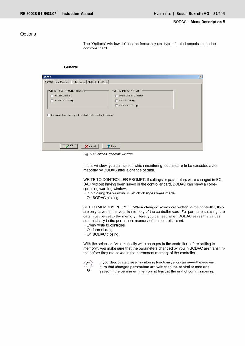
RE 30028-01-B/08.07 | Instuction Manual Hydraulics | Bosch Rexroth AG 87/106
BODAC – Menu Description 5
Options
The "Options" window defines the frequency and type of data transmission to the controller card.
Fig. 63 “Options, general” window
In this window, you can select, which monitoring routines are to be executed auto-matically by BODAC after a change of data.
WRITE TO CONTROLLER PROMPT: If settings or parameters were changed in BO-DAC without having been saved in the controller card, BODAC can show a corre-sponding warning window: - On closing the window, in which changes were made - On BODAC closing
SET TO MEMORY PROMPT: When changed values are written to the controller, they are only saved in the volatile memory of the controller card. For permanent saving, the data must be set to the memory. Here, you can set, when BODAC saves the values automatically in the permanent memory of the controller card: - Every write to controller. - On form closing. - On BODAC closing.
With the selection “Automatically write changes to the controller before setting to memory“, you make sure that the parameters changed by you in BODAC are transmit-ted before they are saved in the permanent memory of the controller.
If you deactivate these monitoring functions, you can nevertheless en-sure that changed parameters are written to the controller card and saved in the permanent memory at least at the end of commissioning.
General

88/106 Bosch Rexroth AG | Hydraulics Instuction Manual | RE 30028-01-B/08.07
5 BODAC – Menu Description
Fig. 64 “Fault Monitoring, Options” window
The operator program BODAC queries at regular intervals the fault states of the con-troller card. This interval can be set here.
Fig. 65 “Options, Table Screen” window
Here, you can select the basic settings for the function “write table to controller“. When the “Table“ screen is closed before the tables were written to the controller, the tables are automatically written to the controller with this setting.
Fault Monitoring
Table Screen
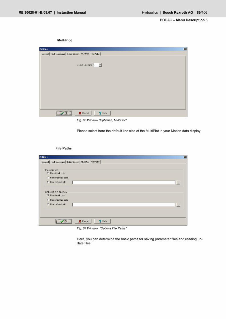
RE 30028-01-B/08.07 | Instuction Manual Hydraulics | Bosch Rexroth AG 89/106
BODAC – Menu Description 5
Fig. 66 Window "Optionen, MultiPlot"
Please select here the default line size of the MultiPlot in your Motion data display.
Fig. 67 Window "Options File Paths"
Here, you can determine the basic paths for saving parameter files and reading up-date files.
MultiPlot
File Paths

90/106 Bosch Rexroth AG | Hydraulics Instuction Manual | RE 30028-01-B/08.07
5 BODAC – Menu Description
Security
Five security levels are available for using BODAC. This allows you to divide BODAC users into groups to ensure that only qualified and trained personnel can change safety-critical settings.
The security levels are defined as follows: Level 4 = Rexroth Bosch AG
Level 3 = Rexroth Bosch AG
Level 2 = Customer Default password “2”
Level 1 = Customer Default password “1”
Level 0 = Customer
WARNING!
The restrictions for settings and changes to parameters and process data have been established for your own security!
Do not attempt through program manipulation or changes of any kind to defeat the security levels.
Personal injury and severe damage to components can result if the card no longer functions correctly due to improper interven-tion.
Such actions will also void any warranties and/or liability on the part of the manufacturer!
Please document the assigned passwords for yourself and your cus-tomers.
The BODAC software always starts up on Level 0.
A user can enter the password he has received for his user group in the “Login” win-dow. After successfully logging in, any changes to settings and parameters allowed for this group can be made.
Fig. 68 “Login” window
In the “Passwords" window you assign the associated password of your choice to the defined security levels.
Login
Passwords

RE 30028-01-B/08.07 | Instuction Manual Hydraulics | Bosch Rexroth AG 91/106
BODAC – Menu Description 5
Fig. 69 “Passwords” window
If the BODAC software is in Level “2”, the following window opens. In this window you can assign a password for the display on the front panel of the controller card.
Fig. 70 “Passwords” Level 2 window
No changes can be made using the display or pushbuttons without knowledge of this password , only the set values can be displayed.
In the “Security : Configure screens” window you specify which user group is given access to the various BODAC windows.
Configure screens
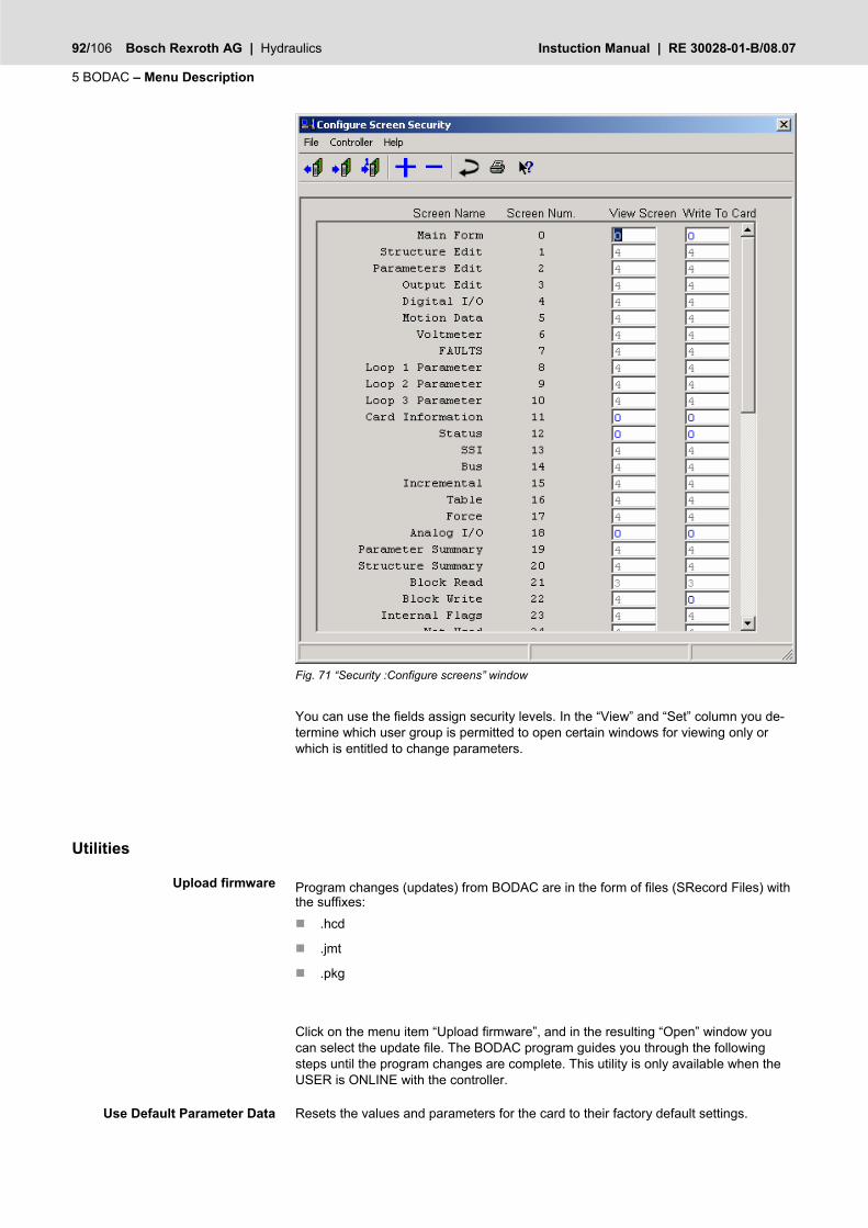
92/106 Bosch Rexroth AG | Hydraulics Instuction Manual | RE 30028-01-B/08.07
5 BODAC – Menu Description
Fig. 71 “Security :Configure screens” window
You can use the fields assign security levels. In the “View” and “Set” column you de-termine which user group is permitted to open certain windows for viewing only or which is entitled to change parameters.
Utilities
Program changes (updates) from BODAC are in the form of files (SRecord Files) with the suffixes:
.hcd
.jmt
.pkg
Click on the menu item “Upload firmware”, and in the resulting “Open” window you can select the update file. The BODAC program guides you through the following steps until the program changes are complete. This utility is only available when the USER is ONLINE with the controller.
Resets the values and parameters for the card to their factory default settings.
Upload firmware
Use Default Parameter Data

RE 30028-01-B/08.07 | Instuction Manual Hydraulics | Bosch Rexroth AG 93/106
BODAC – Menu Description 5
WARNING!
When you reset the values and parameters to their defaults, all the current data will be lost!
5.6 Application Window menu
Command values
Opens the "Commands“ window for parameterizing the command values.
Clicking on the preceding icon, which is a component of the toolbar, also opens the “Command values” window. A list of existing shortcuts for the toolbar can be found in Section 4.2 “BODAC Toolbar”.
See also: Section 3.4 “Configure profiles”.
Configuration 1
Opens the "Configuration 1“ window for configuring the application.
Clicking on the preceding icon, which is a component of the toolbar, also opens the “Configuration 1” window. A list of existing shortcuts for the toolbar can be found in Section 4.2 “BODAC Toolbar”.
See also: Section 3.4 “Configure profiles”.
Pressure controller
Opens the "Pressure controller“ window for parameterizing the pressure controller.
Clicking on the preceding icon, which is a component of the toolbar, also opens the “Pressure controller” window. A list of existing shortcuts for the toolbar can be found in Section 4.2 “BODAC Toolbar”.
See also: Section 3.4 “Configure profiles”.
Motion Data
The “Motion Data” window shows the entire signal sequence of your control loop in real-time.
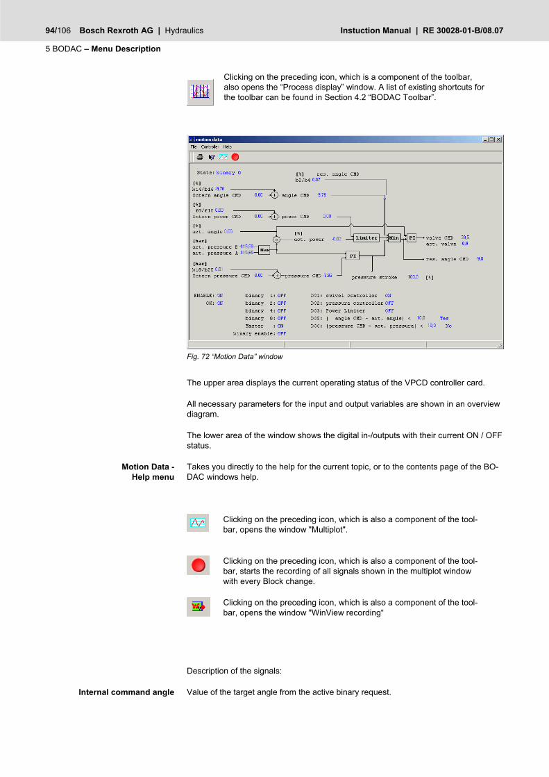
94/106 Bosch Rexroth AG | Hydraulics Instuction Manual | RE 30028-01-B/08.07
5 BODAC – Menu Description
Clicking on the preceding icon, which is a component of the toolbar, also opens the “Process display” window. A list of existing shortcuts for the toolbar can be found in Section 4.2 “BODAC Toolbar”.
Fig. 72 “Motion Data” window
The upper area displays the current operating status of the VPCD controller card.
All necessary parameters for the input and output variables are shown in an overview diagram.
The lower area of the window shows the digital in-/outputs with their current ON / OFF status.
Takes you directly to the help for the current topic, or to the contents page of the BO-DAC windows help.
Clicking on the preceding icon, which is also a component of the tool-bar, opens the window "Multiplot".
Clicking on the preceding icon, which is also a component of the tool-bar, starts the recording of all signals shown in the multiplot window with every Block change.
Clicking on the preceding icon, which is also a component of the tool-bar, opens the window "WinView recording“
Description of the signals:
Value of the target angle from the active binary request.
Motion Data - Help menu
Internal command angle

RE 30028-01-B/08.07 | Instuction Manual Hydraulics | Bosch Rexroth AG 95/106
BODAC – Menu Description 5
Addition of internal and external angle command value
Value of the signal on (b2/b4).
Value of the power command value from the active binary request.
Addition of internal and external power command value.
Value of the actual swivel angle
Value of the actual power
Value of the actual pressure B
Value of the actual pressure A
Value of the pressure command from the active binary request.
Addition of internal and external pressure command value
Value of the valve command
Actual value valve
Multiplot
In the multiplot window the signal trace of selected signals are displayed in graphical form.
Fig. 73 “Multiplot” window
The window is a convenient software representation of an oscilloscope.
Command angle
res. Swivel angle command value
Internal command power
Power command value
Actual swivel angle
Actual power
Actual pressure B
Actual pressure A
Internal pressure command
Pressure command
Valve command
Valve actual

96/106 Bosch Rexroth AG | Hydraulics Instuction Manual | RE 30028-01-B/08.07
5 BODAC – Menu Description
You can get to the “Multiplot” window from any submenu in the “Application window” menu.
The Multiplot is used mainly in the “Motion Data” window (see section “Motion Data”).
Multiplot toolbar
The toobar contains buttons which you can click on to execute all the functions of the real-time oscilloscope.
Fig. 74 Multiplot – Toolbar
Following is a list of the included functions:
Opens the “Save file as” window, in which you can save a signal plot as a file having the suffix “.plt”. The file can be loaded again as needed. You can also import the file in Excel.
Opens the “Open" window, in which you load a previously saved signal plot into the Multiplot window.
Opens the "Open new plot“ window.
Starts the logging process and display of the signal plot for the se-lected signals.
Stops logging of the signal plot and freezes the current display until the plot is activated again by clicking on the “Start” button.
Moves the signal display from right to left. The plot is displayed in scroll mode.
The signal display is fixed. The signal plot begins left and ends at the right border in constant repetition.
All selected signals are shown together in one signal display.
Each signal is shown in its own signal display.
Generates a screenshot of the current display of the multiplot window.
Opens the “Save file as” window, in which you can save the represen-tation of the signal plot in a Windows Meta File (WMF file).
The file is then usable in virtually any common word processing or graphic program.

RE 30028-01-B/08.07 | Instuction Manual Hydraulics | Bosch Rexroth AG 97/106
BODAC – Menu Description 5
Opens the "Print“ window. You get a printout of the multiplot window.
Opens a window in which you can use two selection menus to add analog and digital signals to the display.
Opens a window in which you can delete a selected signal from the multiplot window.
You select a signal for deletion by clicking on its name in the “Signal display legend”. The signal is then highlighted with a white back-ground. Non-selected signals are shown with a gray background.
Shows two cursors on the signal plot of the represented signals. When you select a signal in the “Signal display legend”, you can use the mouse or right/left arrow keys to go to the desired position of the signal plot.
The coordinates are shown in the “Signal display legend” as X- and Y-coordinates.
Deletes the cursors for the X and Y coordinates from the signal dis-play.
Opens a window in which you can set the start condition for displaying the signal plot. A selection menu is used to determine the signal for the start condition. In the “Trigger Units” entry field the value of the trigger parameter in units [Unit] is entered. This value is used to start the signal plot.
1 s/div
The signal display is shown in X- and Y-coordinates with green grid lines. The X-coordinate division can be changed by clicking on the preceding field. In the current representation the signal travels 1 divi-sion in the X direction in one second.
To learn how to change the division of the Y-coordinate, refer to sec-tion "Multiplot signal display legend".
Increases the current Timebase setting with one step. If the current setting is 1s/div this function would increase the X-axis to 500ms/div.
Decreases the current Timebase setting with one step. If the current setting is 1s/div this function would decrease the X-axis to 2s/div.
The user can zoom in on a selected area of the Multiplot window.
Reset the multiplot back to its original size.

98/106 Bosch Rexroth AG | Hydraulics Instuction Manual | RE 30028-01-B/08.07
5 BODAC – Menu Description
Multiplot signal display
The signal is a graphical representation of the signal trace over time.
Fig. 75 Multiplot – signal display
The values of the displayed signals are shown in the Y-direction The unit of the repre-sented pressure command value is [bar], and that of the swivel angle command value is [%]. The X-direction is shown as a time axis.
The display corresponds with a normal oscilloscope.
Multiplot signal display legend
The signal display legend shows the relevant information for the represented signals in tabular form.
Fig. 76 Real-time oscilloscope – Signal display – Legend
In the Parameters column the signals are shown with their names. Clicking on a signal name changes the background to white. This means the signal is selected.
Double-clicking on a signal name opens the “Adjust ” window.
Parameters

RE 30028-01-B/08.07 | Instuction Manual Hydraulics | Bosch Rexroth AG 99/106
BODAC – Menu Description 5
Fig. 77 “Adjust graphs” window
In the “Adjust graphs” window you change the graphical display of the selected signal. Clicking on the "Color" field opens a color table from which you can select a new dis-play color.
The “Thickness” field contains a selection menu for changing the line thickness of the signal.
In the “Min” and "Max" fields you enter the scaling in the Y-direction of the signal dis-play for the selected signal.
The current parameter value is displayed in the signal display legend following the signal name.
The Color column is used for selecting the display color in order to ensure proper association and recognizability in the signal display.
The “X1” and “Y1” columns are directly related to the “Show cursor” button. If you move Cursor 1 to a certain place in the signal plot, you can read off the X/Y coordi-nates of the displayed signal in the X1/Y1 column.
In the “X2”/”Y2” column you read off the coordinates of Cursor 2.
The “dX” (delta X) and “dY” (delta Y) columns show the difference between the X and the Y values.
Color
X1/Y1
X2/Y2
dX/dY

100/106 Bosch Rexroth AG | Hydraulics Instuction Manual | RE 30028-01-B/08.07
5 BODAC – Menu Description
Winview recording
Fig. 78 “Winview Recording” window
The File Menu in the „Winview Recording“ window corresponds to the BODAC main window „File menu“.
Takes you directly to the help function for the current topic, or the contents page of the BODAC windows help.
Buttons are provided for frequently used functions. These are described in section „Toolbar“.
The signals listed in this screen are the same signals used in the BODAC Structure Editor. The Structure Editor screen layout is used to categorize the different signals that can be recorded in an easy to understand representation
Further information regarding the signals used in BODAC that can be selected for recording can be found in the chapter "4.2".
This setup allows the user to select the condition that will trigger the start of the re-cording.
This setup is used for configuring the recording parameters. The number of recording points for all signals combined is limited to 16384. The rate of recording can be set between 2ms and 32766ms. Since the smallest available time step for recording is 2ms the number entered here should be a multiple of 2. The Pretrigger points have a range of 0 – 16384 ms.
Winview Recording – File menu
Winview Recording – Help menu
Winview recording – Toolbar
Trigger Setup
Recording Setup
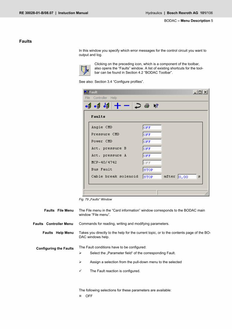
RE 30028-01-B/08.07 | Instuction Manual Hydraulics | Bosch Rexroth AG 101/106
BODAC – Menu Description 5
Faults
In this window you specify which error messages for the control circuit you want to output and log.
Clicking on the preceding icon, which is a component of the toolbar, also opens the “Faults” window. A list of existing shortcuts for the tool-bar can be found in Section 4.2 “BODAC Toolbar”.
See also: Section 3.4 “Configure profiles”.
Fig. 79 „Faults“ Window
The File menu in the “Card information” window corresponds to the BODAC main window “File menu”.
Commands for reading, writing and modifying parameters.
Takes you directly to the help for the current topic, or to the contents page of the BO-DAC windows help.
The Fault conditions have to be configured: Select the „Parameter field“ of the corresponding Fault.
Assign a selection from the pull-down menu to the selected
The Fault reaction is configured.
The following selections for these parameters are available: OFF
Faults File Menu
Faults Controller Menu
Faults Help Menu
Configuring the Faults

102/106 Bosch Rexroth AG | Hydraulics Instuction Manual | RE 30028-01-B/08.07
5 BODAC – Menu Description
No Fault Monitoring.
STOP
If a Fault occurs the controller is stopped, the current to the solenoids becomes zero and the pump swivels to its default position.
The Fault range of the parameters is defined in Chapter 0 „Input Configuration“.
Test jacks
In the “Test jacks” window the signals can be assigned that are available for diagnos-tic purposes on test jack “X1” and “X2” on the front panel of the controller card.
You can assign a signal from the selection menu to test point “X1” (see Fig. 56 „Test jacks“ window).
You can assign a signal from the selection menu to test point “X2” (see Fig. 56 „Test jacks“ window).
Clicking on the preceding icon, which is a component of the toolbar, also opens the “Test points” window. A list of existing shortcuts for the toolbar can be found in Section 4.2 “BODAC Toolbar”.
Fig. 80 “Test jacks” window
Takes you directly to the help for the current topic, or to the contents page of the BO-DAC windows help.
Clicking on the Signal entry field opens a selection menu which contains the available signals.
Test point “X1” has a default value of 100 units. The size of the unit [Unit] for “X2” can be adjusted by the user.
For additional information on the test points of the card, see Technical Bulletin RE 30028-B “Installation and Operation of the Controller Card”.
Test points - Help menu
Signal
Unit

RE 30028-01-B/08.07 | Instuction Manual Hydraulics | Bosch Rexroth AG 103/106
BODAC – Menu Description 5
Configuration 3
Opens the "Configuration 3“ window for parameterizing the application. The window is only visible on Level “2”.
Clicking on the preceding icon, which is a component of the toolbar, also opens the “Configuration 3” window. A list of existing shortcuts for the toolbar can be found in Section 4.2 “BODAC Toolbar”.
See also: Section 3.4 “Configure profiles”.
Open Loop
Opens the "Open Loop“ window for parameterizing the application. The window is only visible on Level “2”.
Clicking on the preceding icon, which is a component of the toolbar in Level 2, also opens the “Pilot” window. A list of existing shortcuts for the toolbar can be found in Section 4.2 “BODAC Toolbar”.
See also: Section 3.4 “Configure profiles”.
Bus Configuration
In this window the user can choose which commands and trigger he wants to use.
Clicking on the preceding icon, which is a component of the toolbar, also opens the “Bus Configuration” window. A list of existing shortcuts for the toolbar can be found in Section 4.2 “BODAC Toolbar”.
See also Section 3.4 “Configure profiles”.
Bus Trigger
This window show the actual state of the bus trigger. You can see here which bit is set in the bus trigger. Each state has it’s own bit. If there are problems with triggers via fieldbus, you can use this screen to be sure to send the correct data.
Clicking on the preceding icon, which is a component of the toolbar, also opens the “Bus Trigger” window. A list of existing shortcuts for the toolbar can be found in Section 4.2 “BODAC Toolbar”.
See also Section 3.4 “Configure profiles”.
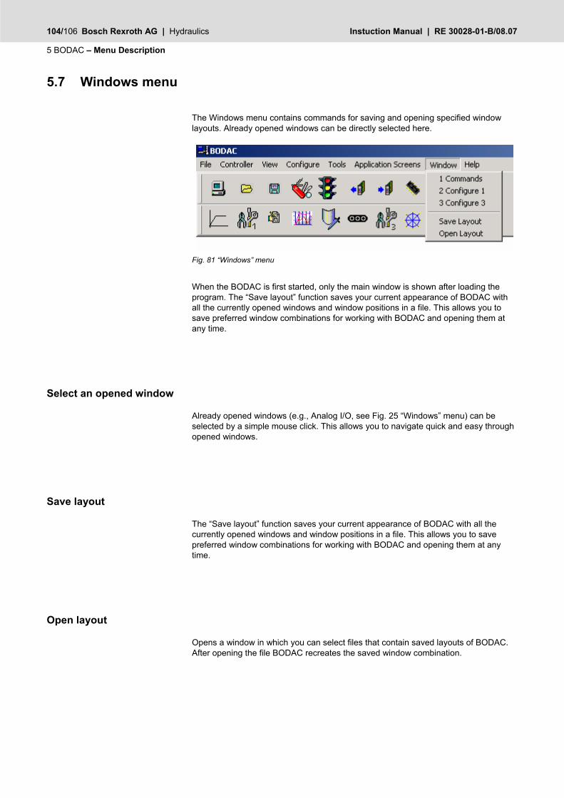
104/106 Bosch Rexroth AG | Hydraulics Instuction Manual | RE 30028-01-B/08.07
5 BODAC – Menu Description
5.7 Windows menu
The Windows menu contains commands for saving and opening specified window layouts. Already opened windows can be directly selected here.
Fig. 81 “Windows” menu
When the BODAC is first started, only the main window is shown after loading the program. The “Save layout” function saves your current appearance of BODAC with all the currently opened windows and window positions in a file. This allows you to save preferred window combinations for working with BODAC and opening them at any time.
Select an opened window
Already opened windows (e.g., Analog I/O, see Fig. 25 “Windows” menu) can be selected by a simple mouse click. This allows you to navigate quick and easy through opened windows.
Save layout
The “Save layout” function saves your current appearance of BODAC with all the currently opened windows and window positions in a file. This allows you to save preferred window combinations for working with BODAC and opening them at any time.
Open layout
Opens a window in which you can select files that contain saved layouts of BODAC. After opening the file BODAC recreates the saved window combination.

RE 30028-01-B/08.07 | Instuction Manual Hydraulics | Bosch Rexroth AG 105/106
BODAC – Menu Description 5
5.8 Help menu
Online help for BODAC can be accessed as follows:
Press the F1 key.
or
Click on the Topics menu in the Help menu.
or
Click on the Help button in the active window.
Fig. 61 “Help” menu
In addition an informative text is displayed on the element you touch with your mouse.
About BODAC…
Information window which provides version information of BODAC.
Topics
Opens the overview of online help for BODAC, from which the user can navigate to any available topic.
Examples
Opens online help for the application (see section 3 "Application: Pump control for A4VS…-H… pumps").


Bosch Rexroth AG HydraulicsZum Eisengießer 197816 Lohr, [email protected]
© This document, as well as the data, specifications and other information set forth in it, are the ex-clusive property of Bosch Rexroth AG. It may not be reproduced or given to third parties without its consent.The data specified above only serve to describe the product. No statements concerning a certain condition or suitability for a certain application can be derived from our information. The information giv-en does notrelease the user from the obligation of own judgment and verification. It must be remembered that our products are subject to a natural process of wear and aging.
Printed in GermanyRE 30028-01-B/08.07Replaces: 08.06