VPLEX Metro with HP Serviceguard A11 - Dell EMC · White Paper Abstract This white paper describes...
22
White Paper Abstract This white paper describes the implementation of HP Serviceguard using EMC ® VPLEX ™ Metro configuration. October 2013 EMC ® VPLEX ™ Metro with HP Serviceguard A11.20
Transcript of VPLEX Metro with HP Serviceguard A11 - Dell EMC · White Paper Abstract This white paper describes...

White Paper
Abstract
This white paper describes the implementation of HP Serviceguard using EMC® VPLEX™ Metro configuration. October 2013
EMC® VPLEX™ Metro with HP Serviceguard A11.20
2
EMC VPLEX Metro and HP Serviceguard
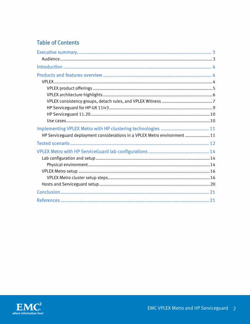
Table of Contents
Executive summary.................................................................................................. 3 Audience ............................................................................................................................ 3
Introduction ............................................................................................................ 4
Products and features overview ............................................................................... 4 VPLEX ................................................................................................................................. 4
VPLEX product offerings ................................................................................................. 5 VPLEX architecture highlights ......................................................................................... 6 VPLEX consistency groups, detach rules, and VPLEX Witness ......................................... 7 HP Serviceguard for HP-UX 11iv3 .................................................................................... 9 HP Serviceguard 11.20 ................................................................................................. 10 Use cases ..................................................................................................................... 10
Implementing VPLEX Metro with HP clustering technologies ................................... 11 HP Serviceguard deployment considerations in a VPLEX Metro environment .................... 11
Tested scenario ..................................................................................................... 12
VPLEX Metro with HP ServiceGuard lab configurations ............................................ 14 Lab configuration and setup ............................................................................................. 14
Physical environment ................................................................................................... 14 VPLEX Metro setup ........................................................................................................... 16
VPLEX Metro cluster setup steps ................................................................................... 16 Hosts and Serviceguard setup .......................................................................................... 20
Conclusion ............................................................................................................ 21
References ............................................................................................................ 21
3
EMC VPLEX Metro and HP Serviceguard
Executive summary EMC® VPLEX™ is an enterprise-class solution that breaks the physical barrier by enabling users to access to a single copy of the data at different geographical locations. It enables the user to geographically stretch virtual and physical host clusters. This enables transparent load sharing between multiple sites while providing the flexibility of relocating workload between sites in anticipation of planned events. In the stretched clusters the cluster nodes are spread across the sites. In the event of unplanned failure at a site, the cluster nodes on the other sites are not impacted providing high availability to the running applications. This solution is made possible by the VPLEX AccessAnywhere clustering technology which allows read/write access to distributed volumes across distance where the volumes have the exact same SCSI LUN identity.
The VPLEX product line includes VPLEX Local (single site SAN federation), VPLEX Metro supporting synchronous distributed volumes with round-trip latency up to 5 ms, and VPLEX Geo support asynchronous distributed volumes with round-trip time up to 50 ms. This paper highlights VPLEX Metro working in conjunction with an HP Serviceguard solution. The solution covered in this white paper focuses on a traditional active/passive cluster configuration.
Main benefits of VPLEX Metro in an HP Serviceguard solution:
• Continuous application availability through network, server, storage, and site failures
• Increased resiliency to entire site failure scenarios or data center maintenance operations without application downtime
• Host cluster nodes are distributed across two sites for maximum availability
EMC Symmetrix® VMAX™ and VNX™ Series are used in this paper as the storage array behind VPLEX clusters. Refer the best practices guide on implementing the storage array for better performance and data protection.
Audience
This white paper is intended for Systems administrators, Storage administrators, and IT architects responsible for architecting, creating, managing, and using IT environments that focus on high availability solutions with HP, VPLEX, and EMC Block storage technologies. The white paper assumes readers are familiar with HP Serviceguard clustering technology, EMC VPLEX, and the EMC Storage array technologies.

4
EMC VPLEX Metro and HP Serviceguard
Introduction The HP Serviceguard solution monitors the information stack and provides services between servers/clusters that allow you to transfer control in the event of a failure, or perform maintenance operations without application downtime. This allows organizations to eliminate system downtime, and continue business processing uninterrupted, even in the case of complete site failures.
This white paper introduces readers to the EMC VPLEX family, VPLEX Metro cluster architecture, and features and functionality that are relevant to an HP Serviceguard deployment. This paper also discusses the resiliency of the HP Serviceguard cluster against different failure conditions.
Products and features overview
VPLEX
EMC VPLEX is a storage virtualization solution for both EMC and non-EMC storage, as shown in Figure 1. The storage behind VPLEX can be heterogeneous, supporting both EMC storage and common arrays from other storage vendors, such as NetApp, HDS, HP, and IBM.
Figure 1. EMC VPLEX Local to federate heterogeneous storage
VPLEX can be extended across geographically dispersed data centers to provide simultaneous access to storage devices through the creation of VPLEX Distributed Virtual Volumes. VPLEX technology provides non-disruptive, heterogeneous data movement and volume management functionality.
Because of these capabilities, VPLEX delivers unique and differentiated value to address four distinct requirements:
• The ability to dynamically move applications and data across different compute and storage infrastructures, either within or across data centers.
5
EMC VPLEX Metro and HP Serviceguard
• The ability to create high-availability storage and compute infrastructure geographically dispersed with unmatched resiliency.
• The ability to provide efficient real-time data collaboration over distance.
• The ability to seamlessly migrate data between storage arrays.
VPLEX product offerings
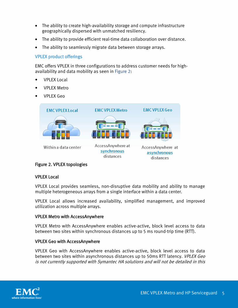
EMC offers VPLEX in three configurations to address customer needs for high-availability and data mobility as seen in Figure 2:
• VPLEX Local
• VPLEX Metro
• VPLEX Geo
Figure 2. VPLEX topologies
VPLEX Local
VPLEX Local provides seamless, non-disruptive data mobility and ability to manage multiple heterogeneous arrays from a single interface within a data center.
VPLEX Local allows increased availability, simplified management, and improved utilization across multiple arrays.
VPLEX Metro with AccessAnywhere
VPLEX Metro with AccessAnywhere enables active-active, block level access to data between two sites within synchronous distances up to 5 ms round-trip time (RTT).
VPLEX Geo with AccessAnywhere
VPLEX Geo with AccessAnywhere enables active-active, block level access to data between two sites within asynchronous distances up to 50ms RTT latency. VPLEX Geo is not currently supported with Symantec HA solutions and will not be detailed in this

6
EMC VPLEX Metro and HP Serviceguard
document. For more information about VPLEX Geo visit http://support.emc.com, search by product: VPLEX Geo.
VPLEX architecture highlights1
The VPLEX family uses a unique clustering architecture to help customers break the boundaries of the data center and allow servers at multiple data centers to have read/write access to shared block storage devices. VPLEX Local includes a single cluster while VPLEX Metro includes two. A VPLEX cluster consists of one, two, or four engines as seen in Table 1. Each VPLEX engine provides SAN/WAN connectivity, cache and processing power with two redundant directors.
Table 1. VPLEX hardware components
Feature Description
VPLEX Cluster Contains one, two, or four engines
VPLEX Engine Contains two directors, management modules, power supplies, battery power and fans
VPLEX Director Contains some of the I/O modules, SSD, CPU and RAM
VPLEX Local uses write-through caching and lets writes pass directly and get acknowledged first at the storage behind the VPLEX volumes before acknowledging them back to the host. With EMC storage, such as Symmetrix VMAX Series and VNX Series, where writes only need to register with the storage persistent cache, application write response time is optimal. VPLEX Metro also uses write-through cache but will acknowledge the writes to the application only once they were registered with both local and remote storage. In all VPLEX deployments, reads can benefit from the VPLEX cache, and in VPLEX Metro, read-hits are served from the local VPLEX cluster cache.
VPLEX logical storage structure
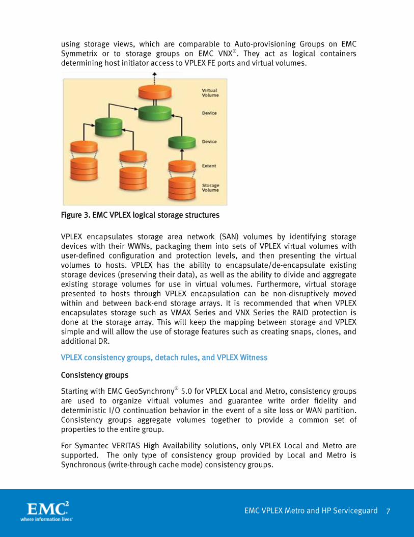
VPLEX encapsulates traditional physical storage array devices and applies three layers of logical abstraction to the storage volumes as seen in Figure 3. Extents are the mechanism VPLEX uses to divide storage volumes. Extents may be all or part of the underlying storage volume. EMC VPLEX aggregates extents and it can apply RAID protection in the device layer.
Devices are constructed using one or more extents and can be combined into more complex RAID schemes and device structures as desired. At the top layer of the VPLEX storage structures are virtual volumes. Virtual volumes are created from devices and inherit the size of the underlying device. Virtual volumes are the elements VPLEX exposes to hosts using its front-end (FE) ports. Access to virtual volumes is controlled
1 The details in this section are based on VPLEX release 5.2 and may be different in other releases. The VPLEX Product Guide provides exact version details.
7
EMC VPLEX Metro and HP Serviceguard
using storage views, which are comparable to Auto-provisioning Groups on EMC Symmetrix or to storage groups on EMC VNX®. They act as logical containers determining host initiator access to VPLEX FE ports and virtual volumes.
Figure 3. EMC VPLEX logical storage structures
VPLEX encapsulates storage area network (SAN) volumes by identifying storage devices with their WWNs, packaging them into sets of VPLEX virtual volumes with user-defined configuration and protection levels, and then presenting the virtual volumes to hosts. VPLEX has the ability to encapsulate/de-encapsulate existing storage devices (preserving their data), as well as the ability to divide and aggregate existing storage volumes for use in virtual volumes. Furthermore, virtual storage presented to hosts through VPLEX encapsulation can be non-disruptively moved within and between back-end storage arrays. It is recommended that when VPLEX encapsulates storage such as VMAX Series and VNX Series the RAID protection is done at the storage array. This will keep the mapping between storage and VPLEX simple and will allow the use of storage features such as creating snaps, clones, and additional DR.
VPLEX consistency groups, detach rules, and VPLEX Witness
Consistency groups
Starting with EMC GeoSynchrony® 5.0 for VPLEX Local and Metro, consistency groups are used to organize virtual volumes and guarantee write order fidelity and deterministic I/O continuation behavior in the event of a site loss or WAN partition. Consistency groups aggregate volumes together to provide a common set of properties to the entire group.
For Symantec VERITAS High Availability solutions, only VPLEX Local and Metro are supported. The only type of consistency group provided by Local and Metro is Synchronous (write-through cache mode) consistency groups.
8
EMC VPLEX Metro and HP Serviceguard
Synchronous consistency groups are defined as follows:
Synchronous consistency groups — Provide a convenient way to apply the same VPLEX cluster detach rules and other properties to a group of volumes in a VPLEX Local or VPLEX Metro configuration, simplifying system configuration and administration on large systems. Volumes in a synchronous group have global or local visibility. Synchronous consistency groups use write-through caching (known as synchronous cache mode in the VPLEX user interface) and with VPLEX Metro are supported on clusters separated by up to 5 ms of latency. This means that VPLEX Metro sends writes to the back-end storage volumes, and acknowledges the write to the application as soon as the back-end storage volumes in both clusters acknowledge the write.
Detach rules
Detach rules are predefined rules that determine consistency group I/O processing semantics whenever connectivity with remote cluster is lost (for example network partitioning or remote cluster failure). In these situations, until communication is restored, most workloads require specific sets of virtual volumes to continue I/O on one cluster and suspend I/O on the other.
In a VPLEX Metro configuration detach rules can depict a static preferred cluster by setting 2: winner:cluster-1, winner:cluster-2 or No Automatic Winner (where the last one specifies no preferred cluster). When the system is deployed without VPLEX Witness (discussed in the next section), I/Os to consistency group devices proceeds on the preferred cluster and are suspended on the non-preferred cluster.
VPLEX Witness
VPLEX Witness, introduced with GeoSynchrony 5.0. VPLEX Witness connects to both VPLEX Metro clusters over the management IP network. By reconciling its own observations with the information reported periodically by the clusters, the VPLEX Witness enables the cluster(s) to distinguish between inter-cluster network partition failures and cluster failures and automatically continue I/O in these situations at the appropriate site. VPLEX Witness affects only virtual volumes that a members of synchronous consistency groups in a VPLEX Metro configuration, and only when the detach rules indicate either cluster-1 or cluster-2 as preferred for the consistency group (that is, VPLEX Witness does not affect consistency groups where No Automatic Winner rule is in effect).
Without VPLEX Witness, if two VPLEX clusters lose contact, the consistency group detach rules in effect define which cluster continues operation and which suspends I/O as explained earlier. The use of detach rules alone to control which site is a winner may add an unnecessary complexity in case of a site failure since it may be necessary to manually intervene to resume I/O to the surviving site.
2 Based on management GUI options. CLI uses slightly different terms to specify the same rules.

9
EMC VPLEX Metro and HP Serviceguard
VPLEX Witness handles such an event dynamically and automatically and this is why it is an absolute requirement for extended Symantec HA deployments. It provides the following features:
• Automatic load balancing between data centers
• Active/active use of both data centers
• Fully automatic failure handling at the storage layer
In order for VPLEX Witness to be able to distinguish correctly between failure conditions, it must be installed in an independent failure domain from either cluster using distinct network interfaces to each. This will eliminate the possibility of a single fault affecting both the cluster and the VPLEX Witness. For example, if the two clusters of a VPLEX Metro configuration are deployed on two different floors of the same data center, deploy the VPLEX Witness on a separate floor. On the other hand, if the two clusters of a VPLEX Metro configuration are deployed in two different data centers, deploy the VPLEX Witness in the third data center. Please refer to the following link for additional details
https://support.emc.com/docu47973_VPLEX-Administration-Guide.pdf?language=en_US
Cache vault
To avoid metadata loss or data loss (when write back caching is used) under emergency conditions, VPLEX uses a mechanism called cache vaulting to safeguard cache information to a persistent local storage.
HP Serviceguard for HP-UX 11iv3
HP Serviceguard solutions protect and keep the applications, data and infrastructure resilient and available for the most critical services running in the data center. HP supports mainstream business applications for high availability providing 24x7 data availability.
The Serviceguard suite consists of the following products:
• HP Serviceguard A.11.20 cluster software (tested solution)
• HP Serviceguard Manager B.03.xx
• HP Serviceguard tool kits for application integration
• HP Serviceguard Extension kits for database support
• HP Serviceguard extended distance support (MetroCluster, ContinentalCluster)
• HP Serviceguard Storage Management Suite (Serviceguard and VCS integration)

10
EMC VPLEX Metro and HP Serviceguard
HP Serviceguard 11.20
HP Serviceguard 11.20 includes file system support for Base VxFS, Full VxFS, CFS, and NFS. The software provides support the following volume managers LVM, VxVM, and CVM.
• LVM is a disk management system that gives you the ability to manage the physical disks on the system. The system can use EMC PowerPath or PVlinks for path management.
• VxFS is a high performance journaling file system that provides easy management and quick-recovery for applications. It delivers scalable performance, continuous availability, increased I/O throughput, and structural integrity.
• Veritas Volume Manager (VxVM) removes the physical limitations of disk storage. Users can configure, share, manage, and optimize storage I/O performance online without interrupting data availability. Veritas Volume Manager also provides easy-to-use, online storage management tools to reduce downtime.
Use cases
The following are some uses cases of high availability infrastructure using VPLEX Metro and HP Serviceguard solutions tested by EMC E-Lab™ for shared data access and high-availability.
Active/Passive cluster configuration
• HP Serviceguard A.11.20
• HP Serviceguard Manager B.03.30

11
EMC VPLEX Metro and HP Serviceguard
Implementing VPLEX Metro with HP clustering technologies This section provides information for implementing VPLEX Metro with HP clustering technologies.
HP Serviceguard deployment considerations in a VPLEX Metro environment
EMC VPLEX breaks the physical barriers of data centers and allows users to access data at different geographical locations concurrently. In an extended Symantec VCS clusters with VPLEX Metro, the active cluster nodes are running on a dedicated VPLEX cluster. For example, in a 4-node cluster implementation, Nodes 1and 2 are active nodes and Nodes 3 and 4 are passive cluster nodes. In case of an unplanned failure on site with active nodes, the passive nodes at the surviving site take the active role and the application continues with minimal downtime.
Figure 5 shows an example of an HP Serviceguard cluster with VPLEX Metro.
Figure 5. HP Serviceguard cluster with VPLEX Metro
12
EMC VPLEX Metro and HP Serviceguard
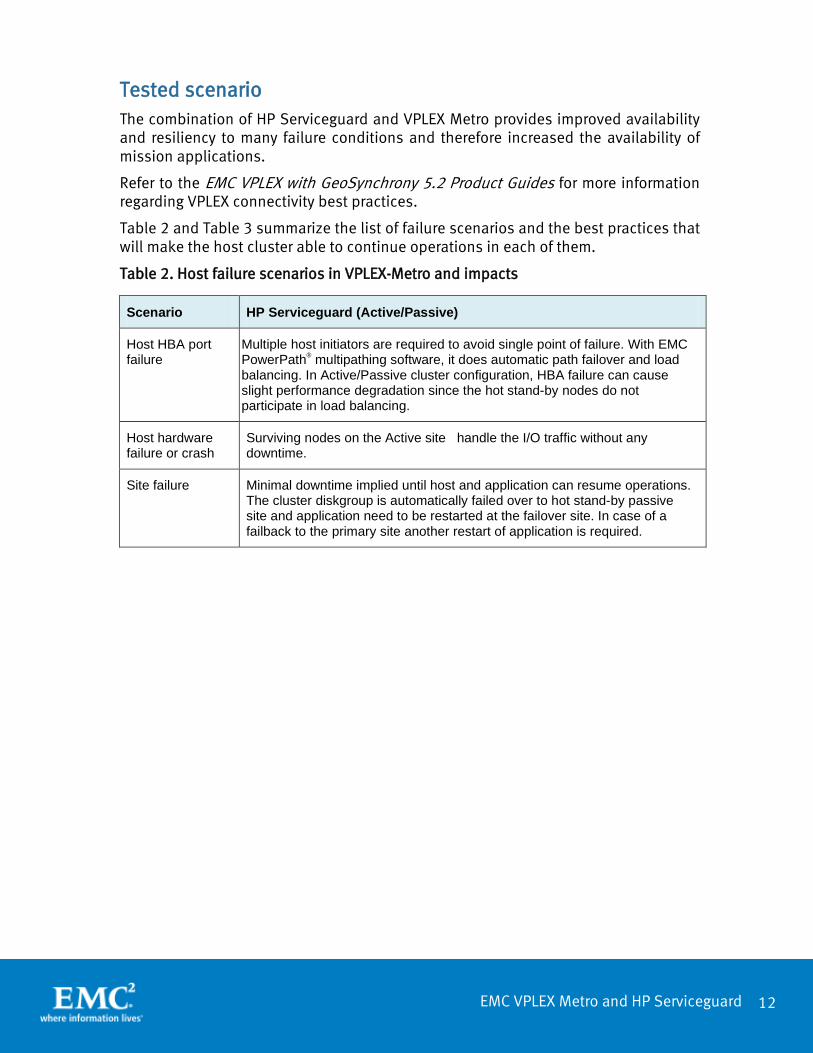
Tested scenario The combination of HP Serviceguard and VPLEX Metro provides improved availability and resiliency to many failure conditions and therefore increased the availability of mission applications.
Refer to the EMC VPLEX with GeoSynchrony 5.2 Product Guides for more information regarding VPLEX connectivity best practices.
Table 2 and Table 3 summarize the list of failure scenarios and the best practices that will make the host cluster able to continue operations in each of them.
Table 2. Host failure scenarios in VPLEX-Metro and impacts
Scenario HP Serviceguard (Active/Passive)
Host HBA port failure
Multiple host initiators are required to avoid single point of failure. With EMC PowerPath® multipathing software, it does automatic path failover and load balancing. In Active/Passive cluster configuration, HBA failure can cause slight performance degradation since the hot stand-by nodes do not participate in load balancing.
Host hardware failure or crash
Surviving nodes on the Active site handle the I/O traffic without any downtime.
Site failure Minimal downtime implied until host and application can resume operations. The cluster diskgroup is automatically failed over to hot stand-by passive site and application need to be restarted at the failover site. In case of a failback to the primary site another restart of application is required.

13
EMC VPLEX Metro and HP Serviceguard
Table 3. VPLEX failure scenarios and impacts
Scenario VPLEX behavior
Single path failure − Front-end (FE) port
VPLEX will continue to provide access to the distributed volume and cluster host multipathing will be expected to failover to the alternate paths.
Single path failure − Back-end (BE) port
VPLEX will switch to provide access to the Metro distributed virtual volume via alternate paths to the same alternate paths to the same BE array and continue to provide access to the Metro distributed volumes exposed to the hosts.
VPLEX hardware component failure
VPLEX has fully redundant directors and power supplies.
VPLEX Interconnect partition
If both sites are still available, the VPLEX Preferred Cluster detach rules will determine which cluster resumes I/Os and which suspends, without downtime for host connected to the surviving Cluster.
VPLEX cluster unavailable
VPLEX Witness will allow I/O to resume at the surviving VPLEX cluster.
Although the architecture of VPLEX Metro is designed to support concurrent access at multiple locations, the current version of the product supports a two-site configuration separated by synchronous distance with a maximum round trip latency of 5 ms between the two sites.
EMC VPLEX Architecture and Deployment: Enabling the Journey to the Private Cloud TechBook, available on EMC Online Support at https://support.emc.com, provides further information on EMC VPLEX Metro configuration.

14
EMC VPLEX Metro and HP Serviceguard
VPLEX Metro with HP ServiceGuard lab configurations
Lab configuration and setup
The following sections describe the technologies and components used in the test cases documented in this paper.
Physical environment
Figure 7 illustrates the overall physical architecture of the HP Serviceguard configuration deployment that was used for the tests shown in this paper. The configuration consisted of four cluster nodes, two at each simulated data center (Site A and Site B).
Figure 7. VPLEX Metro configuration for HP Serviceguard solutions
The hardware setup included setting up Fibre Channel connectivity among the hosts, VPLEX clusters, and EMC storage arrays (VMAX/VNX) to the redundant fabric switches. In each site, the hosts are zoned to their local VPLEX cluster front-end ports and the storage to the VPLEX cluster back-end ports. The VPLEX clusters are zoned to each other for synchronous storage replication. The Serviceguard cluster Private Interconnect between sites uses GigE Ethernet for IP connectivity.
15
EMC VPLEX Metro and HP Serviceguard
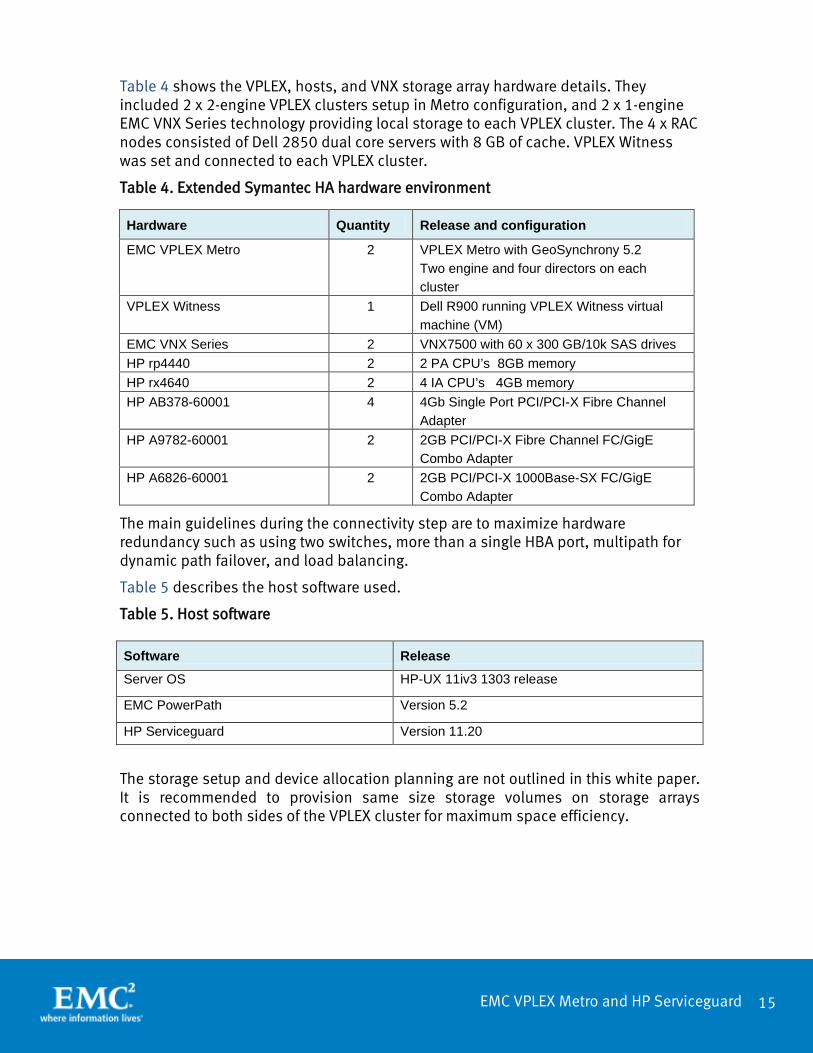
Table 4 shows the VPLEX, hosts, and VNX storage array hardware details. They included 2 x 2-engine VPLEX clusters setup in Metro configuration, and 2 x 1-engine EMC VNX Series technology providing local storage to each VPLEX cluster. The 4 x RAC nodes consisted of Dell 2850 dual core servers with 8 GB of cache. VPLEX Witness was set and connected to each VPLEX cluster.
Table 4. Extended Symantec HA hardware environment
Hardware Quantity Release and configuration
EMC VPLEX Metro 2 VPLEX Metro with GeoSynchrony 5.2 Two engine and four directors on each cluster
VPLEX Witness 1 Dell R900 running VPLEX Witness virtual machine (VM)
EMC VNX Series 2 VNX7500 with 60 x 300 GB/10k SAS drives HP rp4440 2 2 PA CPU’s 8GB memory HP rx4640 2 4 IA CPU’s 4GB memory HP AB378-60001 4 4Gb Single Port PCI/PCI-X Fibre Channel
Adapter HP A9782-60001 2 2GB PCI/PCI-X Fibre Channel FC/GigE
Combo Adapter HP A6826-60001 2 2GB PCI/PCI-X 1000Base-SX FC/GigE
Combo Adapter
The main guidelines during the connectivity step are to maximize hardware redundancy such as using two switches, more than a single HBA port, multipath for dynamic path failover, and load balancing.
Table 5 describes the host software used.
Table 5. Host software
The storage setup and device allocation planning are not outlined in this white paper. It is recommended to provision same size storage volumes on storage arrays connected to both sides of the VPLEX cluster for maximum space efficiency.
Software Release
Server OS HP-UX 11iv3 1303 release
EMC PowerPath Version 5.2
HP Serviceguard Version 11.20

16
EMC VPLEX Metro and HP Serviceguard
VPLEX Metro setup
This section discusses how to set up VPLEX Metro cluster. For further details please refer the EMC VPLEX Configuration Guide at
https://support.emc.com/docu34005_VPLEX-Configuration-Guide.pdf?language=en_US
VPLEX Metro cluster setup steps
Figure 8 lists the main tasks that are required for VPLEX Metro setup.
Figure 8. Overview of VPLEX Metro setup tasks
Note: You must set up both VPLEX Metro clusters as described. You cannot set each cluster up individually and then join them later.

17
EMC VPLEX Metro and HP Serviceguard
Set up VPLEX Metro cluster connectivity
The two key components of VPLEX Metro inter-site communication are FC and IP. Metro can use either Fibre Channel or 10 Gigabit Ethernet for connectivity between directors of each cluster. Connectivity between VPLEX management servers at each cluster are over a secure VPN tunnel. A VPLEX Metro should be set up with redundant (dual fabrics) and completely independent Fibre Channel or 10 Gigabit Ethernet networks between clusters for inter-director communication. This provides maximum performance, fault isolation, fault tolerance, and availability. To check VPLEX Metro Cluster status, run the cluster summary command. For example:
VPlexcli:/> cluster summary
Clusters:
Name Cluster ID TLA Connected Expelled Operational Health State
Status
------- -------- ---------- --------- -------- ------------------ -------
cluster-1 1 PMTELABA000010 true false ok ok
cluster-2 2 PMTELABA000009 true false ok ok
Islands:
Island ID Clusters
--------- --------------------
1 cluster-1, cluster-2
VPLEX Metro host connectivity
To ensure the highest level of connectivity and availability to extended Symantec High Availability cluster nodes even during abnormal operations, each node in the extended Symantec HA deployment model should have at least two physical HBAs, and each HBA should be connected to front-end ports on different directors on EMC VPLEX. This configuration ensures continued availability of the cluster nodes even if one of the front-end ports of the VPLEX goes offline for either planned maintenance events or unplanned disruptions.
When a single VPLEX engine configuration is connected to an extended Symantec cluster node each HBA should be connected to the front-end ports provided on both the A and B directors within the VPLEX engine. Connectivity to the VPLEX front-end ports should consist of first connecting unique hosts to port 0 of each I/O module emulating the front-end directors before connecting additional hosts to the remaining ports on the I/O module. If multiple VPLEX engines are available, the HBAs from the cluster nodes should be connected to different engines.
The connectivity from the VPLEX engines to the storage arrays should follow the best practices recommendation for the array. A detailed discussion of the best practices for connecting the back-end storage is beyond the scope of this paper. The EMC VPLEX Architecture and Deployment: Enabling the Journey to the Private Cloud TechBook provides more information.

18
EMC VPLEX Metro and HP Serviceguard
VPLEX Metro administration
Administration of VPLEX Metro running Geosynchrony 5.2 can be done through the EMC Unisphere™ for VPLEX Management Console. Some additional advanced functionality is provided by with VPLEX CLI. On authenticating to the secure web-based GUI, the user is presented with a set of on-screen configuration options, listed in the order of completion. The EMC Unisphere for VPLEX Management Console online help provides more information about each step in the workflow.
The following table summarizes the steps to be taken from the discovery of the arrays up to the storage being visible to the host.
Step Action 1 Discover available storage
VPLEX Metro automatically discovers storage arrays that are connected to the back-end ports. All arrays connected to each director in the cluster are listed in the Storage Arrays view.
2 Claim storage volumes Storage volumes must be claimed before they can be used in the cluster (with the exception of the metadata volume, which is created from an unclaimed storage volume). Only after storage volume is claimed, it can be used to create extents, devices, and then virtual volumes.
3 Create extents Create extents for the selected storage volumes and specify the capacity.
4 Create devices from extents A simple device is created from one extent and uses storage in one cluster only.
5 Create a virtual volume Create a virtual volume using the device created in the previous step.
6 Register initiators When initiators (hosts accessing the storage) are connected directly or through a Fibre Channel fabric, VPLEX Metro automatically discovers them and populates the Initiators view. Once discovered, you must register the initiators with VPLEX Metro before they can be added to a storage view and access storage. Registering an initiator gives a meaningful name to the port’s WWN, which is typically the server’s DNS name, to allow you to easily identify the host.
7 Create a storage view For storage to be visible to a host, first create a storage view and then add VPLEX Metro front-end ports and virtual volumes to the view. Virtual volumes are not visible to the hosts until they are in a storage view with associated ports and initiators.
8 Create consistency group
Create a consistency group on both VPLEX systems, and add all virtual volumes assigned to extended devices, that require write-order consistency to the consistency group.

19
EMC VPLEX Metro and HP Serviceguard
Figure 9 shows the operational status of VPLEX-Metro cluster. Online Help provides information on provisioning storage from EMC VPLEX.
Figure 9. EMC Unisphere for VPLEX management interface
The browser-based management interface, as seen in Figure 9, shows the system status of various components in the VPLEX Metro various components. Storage from EMC VPLEX is exposed using a logical construct called “Storage View” that is a union of the objects, Registered initiators, VPLEX ports, and Virtual Volume.
• The “Registered initiators” object lists the WWPN of the initiators that need access to the storage. In the case of a Symantec cluster environment, the “Registered initiators” entity contains the WWPN of the HBAs in the cluster servers connected to the EMC VPLEX.
• The “VPLEX ports” contains the front-end ports of the VPLEX array through which the “Registered initiators” access the virtual volumes.
• The “Virtual Volume” object is a collection of volumes that are constructed from the storage volumes that are provided to the EMC VPLEX from the back-end storage arrays.
The Provision Storage tab supports a centralized mechanism for provisioning storage to different cluster members in case of EMC VPLEX Metro. The first step in the process of provisioning storage from EMC VPLEX is the discovery of the storage arrays connected to it. This step needs to be rarely executed since the EMC VPLEX proactively monitors for changes to the storage environment. The second step in the process is the “claiming” of storage that has been exposed to EMC VPLEX. The process of claiming the storage creates the object’s “Storage Volume” that is shown
20
EMC VPLEX Metro and HP Serviceguard
in Figure 9. The Create Storage View wizard enables you to create a storage view and add initiators, ports, and virtual volumes to the view. Once all the components are added to the view, it automatically becomes active. When a storage view is active, hosts can see the storage and begin I/O to the virtual volumes. After creating a storage view, you can only add or remove virtual volumes through the GUI. To add or remove ports and initiators, use the CLI. The EMC VPLEX CLI Guide provides comprehensive information above VPLEX Metro commands.
VPLEX Metro with VPLEX Witness
VPLEX Witness is installed as a closed virtual machine deployed in a failure domain separate from either of the VPLEX clusters (to eliminate the possibility of a single fault affecting both the cluster and the VPLEX Witness). VPLEX Witness connects to both VPLEX clusters over the management IP network. By reconciling its own observations with the information reported periodically by the clusters, the VPLEX Witness enables the cluster(s) to distinguish between inter-cluster network partition failures and cluster failures and automatically resume I/O in these situations.
Hosts and Serviceguard setup
This section covers the recommendations for configuring Serviceguard on HP-UX 11iv3 in an active/passive cluster configuration. Please note that the Serviceguard implementations using VPLEX-Metro are the same for all supported OS revisions supported with HP Serviceguard A.11.20 solutions.
Refer to the EMC Support Matrix, available at https://elabnavigator.emc.com, for supported configurations.
The cluster can be deployed using either cluster wide DSF’s (device special files) or you can use a traditional approach to configuring your cluster. Detailed cluster installation and configuration guidelines are available at http://h20628.www2.hp.com/km-ext/kmcsdirect/emr_na-c03511798-5.pdf.

21
EMC VPLEX Metro and HP Serviceguard
Conclusion EMC VPLEX Metro running the GeoSynchrony operating system is an enterprise-class SAN-based federation technology that aggregates and manages pools of Fibre Channel attached storage arrays that can be either co-located in a single data center or across multiple data centers that are geographically separated by metro distances. Furthermore, with a unique scale-up and scale-out architecture, EMC VPLEX’s advanced data caching and distributed cache coherency provide workload resiliency, automatic sharing, and balancing and failover of storage domains, and enable both local and remote data access with predictable service levels.
HP Serviceguard cluster dispersed in two data centers within metro distance, backed by the capabilities of EMC VPLEX Metro, provides simplified deployment topologies and storage administration, non-disruptive storage scalability and tech refresh.
In addition, the capability of EMC VPLEX to provide non-disruptive, heterogeneous data movement and volume management functionality within synchronous distances enables customers to offer nimble, efficient, and cost-effective cloud services spanning multiple physical locations.
References The following documents include more information on VPLEX Metro can be found on https://support.emc.com.
• EMC VPLEX Metro Witness – Technology and High Availability TechBook
• Implementation and Planning Best Practices for EMC VPLEX Technical Notes
• EMC VPLEX with GeoSynchrony 5.2 Product Guides
• Conditions for stretched hosts cluster support on EMC VPLEX Metro
For product-specific information, refer to:
• VPLEX at http://www.emc.com/storage/vplex/vplex.htm
• Symantec High Availability at http://www8.hp.com/us/en/products/servers/hp-ux.html?compURI=1454628
22
EMC VPLEX Metro and HP Serviceguard
CONTACT US To learn more about how EMC products, services, and solutions can help solve your business and IT challenges, contact your local representative or authorized reseller—or visit us at www.EMC.com.
Copyright © 2013 EMC Corporation. All Rights Reserved. EMC believes the information in this publication is accurate as of its publication date. The information is subject to change without notice. The information in this publication is provided “as is.” EMC Corporation makes no representations or warranties of any kind with respect to the information in this publication, and specifically disclaims implied warranties of merchantability or fitness for a particular purpose. Use, copying, and distribution of any EMC software described in this publication requires an applicable software license. For the most up-to-date listing of EMC product names, see EMC Corporation Trademarks on EMC.com. EMC2, EMC, the EMC logo, and the RSA logo are registered trademarks or trademarks of EMC Corporation in the United States and other countries. Red Hat is a registered trademark of Red Hat, Inc. in the United States and/or other jurisdictions. All other trademarks used herein are the property of their respective owners. © Copyright 2013 EMC Corporation. All rights reserved. Published in the USA. 10/13 White Paper H12381