Vortex Ring State Simulation Using Actuator Disc · these simulations an actuator disc model of fan...
6
Vortex Ring State Simulation Using Actuator Disc Adam Dziubinski Wienczyslaw Stalewski Instytut Lotnictwa / Institute of Aviation Computational Fluid Dynamics Department Al. Krakowska 110/114, Warsaw 02-256, Poland E-mail: [email protected] ; [email protected] KEYWORDS CFD, Helicopter Analysis. ABSTRACT This work contains the simulation results of vortex ring state appearance and evolution around main rotor of a helicopter. These calculations were based on solution of Navier-Stokes equations using the Fluent code. During these simulations an actuator disc model of fan has been used. This model assumes that a fan is a pressure jump generating surface. Two meshes have been used during this simulation: three dimensional and axisymmetric two dimensional. The most of the cases has been calculated using steady flow solution, but unsteady model also has been applied. Main goal of this work was a calibration of model, in terms of simplifications influence on results, and also in comparison with experimental results. It is assumed, that after a proper calibration, this model can be used in further flight safety methods of VRS elimination research. 1. INTRODUCTION In a specific conditions of a helicopter flight, around the main rotor may appear a toroidal structure called a vortex ring. This is very dangerous phenomenon, because the rotor stops pulling a helicopter up, instead wasting its power to propel the vortex around it. The fully developed vortex ring state is shown in Fig. 1. Fig.1 fully developed vortex ring state.[2] Vortex Ring State (VRS, called also "settling with power") appears in a following way: the air stream flowing through a rotor meets with a surrounding air which has opposite velocity. The friction forces caused by the external flow are destroying the continuity of this stream, and turning it back to upper (suction) side of the rotor. Then this air goes again by the rotor closing the loop of vortex. So the vortex is propelled by the rotor on one side, and by surrounding flow on the other. It is clearly shown in Fig. 1. Vortex ring state on main rotor of a helicopter may appear not only in vertical flight, but also in forward flight. In Fig. 2 a theoretical range of VRS appearance depending on horizontal and vertical velocities of a helicopter is shown. A VRS starts to appear at the descent velocities around 0.5 of velocity induced by the rotor, and stops at 1.5 of this velocity. Using this chart one can figure out, that there is only several ways to get rid of the vortex ring. Pilot can: • try to enforce forward flight, which can blow backward all the vortices from a rotor. • try to enforce higher descent velocity than a "bottom part" of VRS velocities range. Unfortunately this maneuver cannot be done in proximity of ground. • try to climb up from VRS by increasing power. It is known, that required power for such maneuver is about twice the power needed to hover flight, and there is only one helicopter that can do this: Sikorsky S-64 Skycrane without container mounted. Fig.2 Flight conditions most dangerous in terms of VRS phenomena appearance. The problem is, that a vortex ring has a strong tendency to stabilize itself around a rotor. Increasing a power does not cause a blowing out the vortex, but instead it causes continuous increasing of a vortex rotational velocity. The only exception is a situation, when an induced velocity increases dramatically. This is not usual, Proceedings 21st European Conference on Modelling and Simulation Ivan Zelinka, Zuzana Oplatková, Alessandra Orsoni ©ECMS 2007 ISBN 978-0-9553018-2-7 / ISBN 978-0-9553018-3-4 (CD)
Transcript of Vortex Ring State Simulation Using Actuator Disc · these simulations an actuator disc model of fan...

Vortex Ring State Simulation Using Actuator Disc
Adam Dziubinski
Wienczyslaw Stalewski Instytut Lotnictwa / Institute of Aviation
Computational Fluid Dynamics Department Al. Krakowska 110/114, Warsaw 02-256, Poland E-mail: [email protected]; [email protected]
KEYWORDS CFD, Helicopter Analysis. ABSTRACT
This work contains the simulation results of vortex ring state appearance and evolution around main rotor of a helicopter. These calculations were based on solution of Navier-Stokes equations using the Fluent code. During these simulations an actuator disc model of fan has been used. This model assumes that a fan is a pressure jump generating surface. Two meshes have been used during this simulation: three dimensional and axisymmetric two dimensional. The most of the cases has been calculated using steady flow solution, but unsteady model also has been applied. Main goal of this work was a calibration of model, in terms of simplifications influence on results, and also in comparison with experimental results. It is assumed, that after a proper calibration, this model can be used in further flight safety methods of VRS elimination research. 1. INTRODUCTION
In a specific conditions of a helicopter flight, around the main rotor may appear a toroidal structure called a vortex ring. This is very dangerous phenomenon, because the rotor stops pulling a helicopter up, instead wasting its power to propel the vortex around it. The fully developed vortex ring state is shown in Fig. 1.
Fig.1 fully developed vortex ring state.[2] Vortex Ring State (VRS, called also "settling with power") appears in a following way: the air stream flowing through a rotor meets with a surrounding air which has opposite velocity. The friction forces caused
by the external flow are destroying the continuity of this stream, and turning it back to upper (suction) side of the rotor. Then this air goes again by the rotor closing the loop of vortex. So the vortex is propelled by the rotor on one side, and by surrounding flow on the other. It is clearly shown in Fig. 1. Vortex ring state on main rotor of a helicopter may appear not only in vertical flight, but also in forward flight. In Fig. 2 a theoretical range of VRS appearance depending on horizontal and vertical velocities of a helicopter is shown. A VRS starts to appear at the descent velocities around 0.5 of velocity induced by the rotor, and stops at 1.5 of this velocity. Using this chart one can figure out, that there is only several ways to get rid of the vortex ring. Pilot can: • try to enforce forward flight, which can blow backward all the vortices from a rotor. • try to enforce higher descent velocity than a "bottom part" of VRS velocities range. Unfortunately this maneuver cannot be done in proximity of ground. • try to climb up from VRS by increasing power. It is known, that required power for such maneuver is about twice the power needed to hover flight, and there is only one helicopter that can do this: Sikorsky S-64 Skycrane without container mounted.
Fig.2 Flight conditions most dangerous in terms of VRS phenomena appearance. The problem is, that a vortex ring has a strong tendency to stabilize itself around a rotor. Increasing a power does not cause a blowing out the vortex, but instead it causes continuous increasing of a vortex rotational velocity. The only exception is a situation, when an induced velocity increases dramatically. This is not usual,
Proceedings 21st European Conference on Modelling and SimulationIvan Zelinka, Zuzana Oplatková, Alessandra Orsoni ©ECMS 2007ISBN 978-0-9553018-2-7 / ISBN 978-0-9553018-3-4 (CD)

because a lot of power is needed even to stop descending. Previously mentioned strong tendency to stabilize the vortex around the rotor is very dangerous during an attempt to escape forward from VRS. Unfortunately this is the only solution in proximity of ground. Most feasible method is a fast descent, but it requires a reserve of altitude and velocity. It leads to determine such flight rules, which allow a helicopter to stay in dangerous flight conditions for a very short time.
Fig. 3 Ranges of forward and descent speeds, where as a unit has been used the induced velocity. [2] In Fig. 3 a similar chart for the real helicopter is shown. The range of VRS is much wider than a theoretical analysis could determine. It is also hard to achieve the autorotation conditions (curve “A”) not passing through the VRS area. The Vortex Ring State appearance has a strong influence on flight safety. This is the reason, why a research concerning VRS is so important. In such research very helpful could be the computer simulation. In general, the computer methods of flow simulations around the rotor of a helicopter are based on a whole spectrum of CFD methods: simplified methods of vortex line on one hand, and unsteady Navier-Stokes solutions around complex geometry of rotor on the other. In this work an alternative methodology of computer modeling of flow around helicopter rotor is introduced. Methodology is based on combination of flow modeling using Navier - Stokes unsteady solution with simplified pressure jump surface (actuator disc, FAN model) representation of rotor. Because of wide range of problems according to VRS, this work contains only partial analysis of flowfield simulation around helicopter during VRS appearance, as follows:
• validation of simplified modeling of rotor using pressure jump surface in VRS analysis
• simulation of dynamic phenomena leading to VRS
• simulation of dynamic maneuvers allowing to escape from VRS state
2. METHODOLOGY OF VORTEX RING STATE SIMULATION.
Simulation of VRS has been done using commercial FLUENT ® [1] code, being a widely recognized CFD industrial standard. In general this code solves the Navier-Stokes equations using finite volume method. Flow equations are solved in a given domain, represented by using structural, non-structural or mixed computational mesh. Code allows to use a wide spectrum of computational methods. For an analysis of flowfield around rotors, this code also contains a lot of computational models. Most complex model is modeling of unsteady flow around rotor with exact model of geometry. This type of solution is very time consuming, and requires a lot of computer resources. Time and resource efficiency is crucial during modeling of maneuvering helicopter, and especially during VRS analysis. This phenomenon is highly unsteady and nonperiodical, and requires a very time consuming computational simulation. In that case, to proceed in acceptable time with such simulation, simplification of flow modeling is strongly taken into account. In presented approach a computational model of rotor based on pressure jump surface was used. In Fig. 4 basic geometrical conditions of a model are shown. A helicopter is represented by a simplified fuselage and infinitely thin disc (so called actuator disc) which represents the rotor. Depending on a specific requirements a shape of fuselage is more or less simplified. Actuator disc can model both, main and tail rotors. In presented research the model of helicopter shown in Fig. 4. was applied.
Fig. 4 Geometrical assumptions of computational model. The model of a helicopter described above, was surrounded by a computational domain, as it is shown in Fig. 5. In case of unsteady flight , it was assumed that whole computational domain is moving with a helicopter according to assumed kinematics. Flow equations were solved in non inertial reference frame attached to the helicopter. Boundary conditions were assumed as shown in Fig 5. The surface of fuselage was considered as a solid wall. On external surfaces the far field condition was assumed. An additional condition was set on actuator disc modeling main rotor. The FLUENT boundary condition type FAN was applied.

Fig. 5 Structure of considered flowfield. This type of condition allows to enforce on given surface an assumed pressure jump and also a distribution of tangential components of velocity vector. This type of boundary condition is used for simplified modeling of the disturbances of flowfield generated by vents and fans. In described approach this type of boundary condition was used for modeling the effects generated by rotating main rotor of a helicopter. Basic parameter defining a FAN is a pressure jump distribution. In presented approach following radial distributions on rotor disc were applied:
• Pressure jump defined by a load distribution along a blade
• Linear distribution of radial velocity • Linear distribution of swirl velocity
Exemplary of distributions have been shown in Fig 6.
Fig. 6 Distributions of pressure jump (dP), swirl velocity (vt) and radial velocity (vr) on actuator disc. The described computational problem requires a specific mesh. In a structure of this mesh the disc modeling rotating elements of fan have to be distinguished. Example of such mesh has been shown in Fig 7, 8. Fig 7 is an overview of a mesh surrounding a helicopter in its central part. Flowfield dimensions are extremely large in comparison with helicopter dimensions.
Details of mesh are shown in Fig 8. A hybrid structural - nonstructural mesh has been used.
Fig.7 Example of mesh used for VRS computations
Fig.8 Example of hybrid mesh surrounding the model of a helicopter. 3. THE RESULTS OF CFD SIMULATIONS.
Fully three-dimensional simulation of VRS has been predeceased by simple two-dimensional axisymmetric simulation. In that case a version of FLUENT code allowing to solve two-dimensional problems has been used. Analysis concerned an isolated rotor. At the beginning a hover flight condition has been determined. Next, an analysis of flowfield for different values of descent velocity has been done. The results are shown in Fig 9. In the first phase of simulation the flow around the rotor is typical for hover flight. Following color maps are showing, phase by phase, a process of VRS formation and destruction. Most significant VRS can be observed in some specific range of descent velocity. Above this range the vortex is blown up from the rotor. Further computations were done for fully three-dimensional case using the mesh shown in Fig 7 and 8. The simulation included two different cases of helicopter flight: • the descent with constant acceleration • the escape from VRS forward, with constant acceleration.
Rotor surface, actuator disc (fan model)
Surface of the fuselage, wall boundary condition
Side surface, Pressure far field
boundary condition
Pressure outlet surface
Pressure inlet surface

Fig.9 Result of 2d simulation for hover and various velocities of descent. 3.1 Simulation of descent flight with constant acceleration.
In a first part of three-dimensional computations a simulation of helicopter descent flight with constant acceleration was considered.(Fig.10.). The following cinematic data was assumed: descent acceleration: aw = 2 m/s2 forward acceleration: av = 0 m/s2 ranges of velocities: descent: W = 0 - 40 m/s forward: V = 0 m/s timeframe of simulation: T = 20 s
The results of the simulation are shown in Fig. 11. and 12. The pictures shows the pathlines around a helicopter rotor.All characteristic phases of VRS are shown. Flow generated by the rotor is turned back over the surface of a propeller. When a descent velocity, similar to velocity induced by the rotor is achieved, a vortex ring appears, and it exists in some range of descent velocity. In reality,
the descent velocity is stabilizing itself in this range, and it is hard to get rid of VRS. Similarity with stall of an aircraft is adequate, in terms of hardness to avoid, danger in ground proximity and flight safety.
W=0V= 0
W=4V= 0
W=8V= 0
W=12V= 0
W=16V= 0
W=20V= 0
W=24V= 0
W=28V= 0
W=0V= 0
W=4V= 0
W=8V= 0
W=12V= 0
W=16V= 0
W=20V= 0
W=24V= 0
W=28V= 0
Fig.11 Path lines flowing from the rotor disc in given timeframes, during descent flight , front view. In a described simulation the vertical velocity was increased further, to push a helicopter through a vortex ring state. Therefore a verification of model, in terms of blow up a vortex from rotor when a descent velocity is high enough, was possible.
ww
Fig.10 Kinematics of helicopter during descent with constant acceleration.
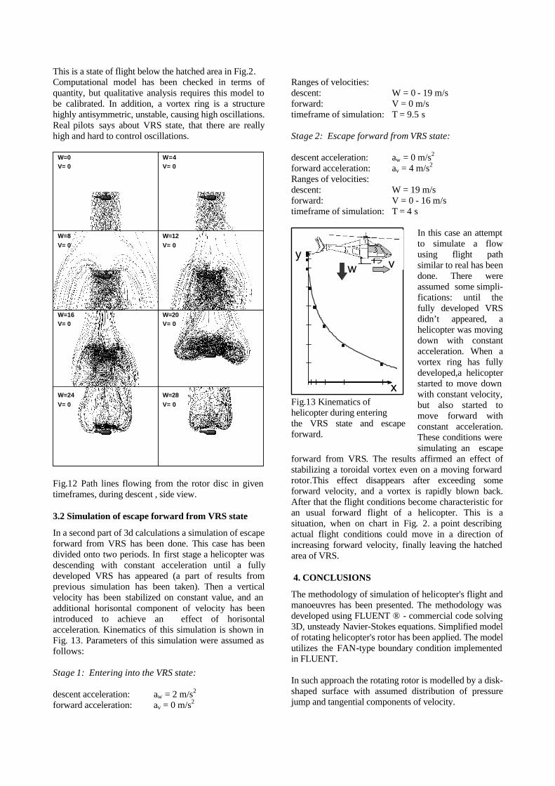
This is a state of flight below the hatched area in Fig.2. Computational model has been checked in terms of quantity, but qualitative analysis requires this model to be calibrated. In addition, a vortex ring is a structure highly antisymmetric, unstable, causing high oscillations. Real pilots says about VRS state, that there are really high and hard to control oscillations.
W=0V= 0
W=4V= 0
W=8V= 0
W=12V= 0
W=16V= 0
W=20V= 0
W=24V= 0
W=28V= 0
W=0V= 0
W=4V= 0
W=8V= 0
W=12V= 0
W=16V= 0
W=20V= 0
W=24V= 0
W=28V= 0
Fig.12 Path lines flowing from the rotor disc in given timeframes, during descent , side view. 3.2 Simulation of escape forward from VRS state
In a second part of 3d calculations a simulation of escape forward from VRS has been done. This case has been divided onto two periods. In first stage a helicopter was descending with constant acceleration until a fully developed VRS has appeared (a part of results from previous simulation has been taken). Then a vertical velocity has been stabilized on constant value, and an additional horisontal component of velocity has been introduced to achieve an effect of horisontal acceleration. Kinematics of this simulation is shown in Fig. 13. Parameters of this simulation were assumed as follows: Stage 1: Entering into the VRS state: descent acceleration: aw = 2 m/s2 forward acceleration: av = 0 m/s2
Ranges of velocities: descent: W = 0 - 19 m/s forward: V = 0 m/s timeframe of simulation: T = 9.5 s Stage 2: Escape forward from VRS state: descent acceleration: aw = 0 m/s2 forward acceleration: av = 4 m/s2 Ranges of velocities: descent: W = 19 m/s forward: V = 0 - 16 m/s timeframe of simulation: T = 4 s
In this case an attempt to simulate a flow using flight path similar to real has been done. There were assumed some simpli- fications: until the fully developed VRS didn’t appeared, a helicopter was moving down with constant acceleration. When a vortex ring has fully developed,a helicopter started to move down with constant velocity, but also started to move forward with constant acceleration. These conditions were simulating an escape
forward from VRS. The results affirmed an effect of stabilizing a toroidal vortex even on a moving forward rotor.This effect disappears after exceeding some forward velocity, and a vortex is rapidly blown back. After that the flight conditions become characteristic for an usual forward flight of a helicopter. This is a situation, when on chart in Fig. 2. a point describing actual flight conditions could move in a direction of increasing forward velocity, finally leaving the hatched area of VRS. 4. CONCLUSIONS
The methodology of simulation of helicopter's flight and manoeuvres has been presented. The methodology was developed using FLUENT ® - commercial code solving 3D, unsteady Navier-Stokes equations. Simplified model of rotating helicopter's rotor has been applied. The model utilizes the FAN-type boundary condition implemented in FLUENT. In such approach the rotating rotor is modelled by a disk-shaped surface with assumed distribution of pressure jump and tangential components of velocity.
w vy
x
w vy
x Fig.13 Kinematics of helicopter during entering the VRS state and escape forward.

The methodology was applied to study the phenomenon called Vortex Ring State which may appear in specific conditions of helicopter's flight and which is a very dangerous from point of view of flight safety. Performed simulations concerned typical flight conditions leading to an appearance of Vortex Ring State. After achieving this state of flight the simulations have been continued realising different ways of rescue, including fast descent or forward flight.
W=0V= 0
W=12V= 0
W=19V= 0
W=19V= 4
W=19V= 6
W=19V= 8
W=19V= 12
W=19V= 16
W=0V= 0
W=12V= 0
W=19V= 0
W=19V= 4
W=19V= 6
W=19V= 8
W=19V= 12
W=19V= 16
Fig.14 Path lines flowing from the rotor disc in given timeframes, during escape forward simulation . Front view. Performed simulations confirmed that presented methodology gives qualitatively good results of helicopter manoeuvres simulations leading to and recovering from the Vortex Ring State. Therefore the methodology seems to be a very useful tool supporting research of helicopter flight safety. To use for quantitative analysis the method needs to be calibrated and developed. It especially concerns the simulation of mutual interactions between external flow and distribution of flow parameters on the rotor disk. The good way to achieve this, seems to be a coupling of presented methodology with the Blade Element Theory which evaluates interactions between rotor blades and fluid. This approach is considered as a best way to get a good, cost-efficient computational tool for analysis of
very complicated phenomena appearing during helicopter's flight and manoeuvres.
W=0V= 0
W=12V= 0
W=19V= 0
W=19V= 4
W=19V= 6
W=19V= 8
W=19V= 12
W=19V= 16
W=0V= 0
W=12V= 0
W=19V= 0
W=19V= 4
W=19V= 6
W=19V= 8
W=19V= 12
W=19V= 16
Fig.15 Path lines flowing from the rotor disc in given timeframes, during escape forward simulation. Side view. SYMBOLS DESCRIPTION
av - vertical acceleration aw - acceleration dP - pressure jump on surface of the actuator disc T - time V - forward (horizontal) velocity Vi - induced velocity Vt - swirl velocity Vr - radial velocity W - descent velocity
BIBLIOGRAPHY
1. FLUENT 6.1 User's Guide. Fluent Inc. February 2003.
2. http://www.copters.com 3. W. J. Prosnak “Mechanika Plynów” Warsaw
1971