
Vortex-Induced Vibration Characteristics of a PTC Cylinder ...
Upload
trannguyetCategory
view
227download
0
Abstract—A numerical simulation of vortex-induced vibration of
a 2-dimensional elastic circular cylinder with two degree of freedom under the uniform flow is calculated when Reynolds is 200. 2-dimensional incompressible Navier-Stokes equations are solved with the space-time finite element method, the equation of the cylinder motion is solved with the new explicit integral method and the mesh renew is achieved by the spring moving mesh technology. Considering vortex-induced vibration with the low reduced damping parameter, the variety trends of the lift coefficient, the drag coefficient, the displacement of cylinder are analyzed under different oscillating frequencies of cylinder. The phenomena of locked-in, beat and phases-witch were captured successfully. The evolution of vortex shedding from the cylinder with time is discussed. There are very similar trends in characteristics between the results of the one degree of freedom cylinder model and that of the two degree of freedom cylinder model. The streamwise vibrations have a certain effect on the lateral vibrations and their characteristics.
Keywords—Fluid-structure interaction, Navier-Stokes equation, Space-time finite element method, vortex-induced vibration.
I. INTRODUCTION
LUID-STRUCTURE interactions occur in many engineering fields, such as nuclear engineering, ocean
engineering, vehicle engineering and wind engineering. The vortex-induced vibration caused by the vortex shedding from the cylinder is a typical fluid-interaction problem. The periodic flow force, generated by the periodic vortex shedding, affect the cylinder vibration, at the same time, the oscillating cylinder will affect the fluid flow around cylinder, the fluid force and the vortex pattern, thus, a complex fluid-structure interaction forms. Flow-induced vibrations of an elastic circular cylinder are strongly nonlinear. It is very important to research vortex-induced vibration for the design of a variety of engineering structures. Numerous studies have been carried out on the vortex-induced vibration of an elastic circular cylinder.
The vortex-induced vibration experiment in the laminar regime is very few. Anagnostopoulos & Bearman [1] conducted a vortex-induced vibration experiment with one degree of freedom over a range, Re=90-150. The locked-in and
T. Li is with the Traction Power State Key Laboratory, Southwest Jiaotong
University, Chengdu, Sichuan Province, China (phone: +86-28-8760-0147; e-mail: [email protected]).
J.Y.Zhang is with the Traction Power State Key Laboratory, Southwest Jiaotong University, Chengdu, Sichuan Province, China (phone: +86-28-8646-6040; e-mail: [email protected]).
beat phenomena were captured. Khalak [2] conducted a similar experiment. The results shows that for large mass ratios, the actual cylinder oscillation frequency at resonance will be close to the vortex shedding frequency for the fixed cylinder, and also close to the vortex shedding frequency. But, that’s not suitable for small mass ratios. Khalak & Williamson [3] examined a hydroelastic cylinder with a very low mass damping in the lateral-flow. It shows that the response of the cylinder has two resonance branches, a lower branch and an upper branch. Brika & Laneville were the first to examine the 2P vortex pattern using a vibrating cable in a wind tunnel. They found a clear correspondence of the 2S pattern with the initial branch of response, and the 2P pattern with the lower branch.
On the other hand, numerous numerical works have been carried out. Williamson & Roshko [4] studied the vortex wake patterns for a cylinder translating in a sinusoidal trajectory over a variation of amplitudes and frequency ratios. They defined a whole set of different regimes for vortex patterns, such as the 2S, 2P and P+S modes. Guilmineau [5] analyzed the vortex-induced vibration of cylinder with low mass-damping in a turbulent flow. Dong [6] discussed the flow past a fixed and oscillating cylinder at Re=10000. Al-Jamal [7] considered vortex-induced vibration at a moderate Reynolds. A number of two-dimensional numerical simulation at Re=100-200 were carried out. Antoine [8] discussed the forced and free oscillating cylinder in a cross-flow at low Reynolds number. Zhou [9] studied a uniform flow past an elastic circular cylinder using the discrete vortex method at the Reynolds=200. Analyses of the cylinder responses, the damping, the induced forces, the vortex shedding frequency and the vortex structure in the wake have been carried out. It is shown that a one degree of freedom structural model yields results that are only in qualitative agreement with a two degree of freedom model. Li [10] analyzed the vortex-induced vibration of an elastic circular cylinder at Re=200, the locked-in, beat and phaseswith phenomena were captured. Besides, the vortex structure, the unsteady lift and drag coefficient, and the displacement at various natural frequency of the cylinder were discussed. Meneghini & Bearman [11] demonstrated that the 2S mode persists up to a level of A=0.6, beyond which they found the P+S mode. But there is a clear correspondence between the nonexistence of any free-vibration amplitude A in excess of 0.6. Sarpkaya [12] worked with XY vibrations and demonstrated a broad regime of synchronization, similar to Y-only vibration. The results show that structure in XY motion do not lead to surprising changes in the expected maximum
Vortex-Induced Vibration Characteristics of an Elastic Circular Cylinder
T. Li, J.Y. Zhang, W.H. Zhang and M.H. Zhu
F
World Academy of Science, Engineering and TechnologyInternational Journal of Mathematical, Computational, Physical, Electrical and Computer Engineering Vol:3, No:12, 2009
1082International Scholarly and Scientific Research & Innovation 3(12) 2009 scholar.waset.org/1999.7/11024
Inte
rnat
iona
l Sci
ence
Ind
ex, M
athe
mat
ical
and
Com
puta
tiona
l Sci
ence
s V
ol:3
, No:
12, 2
009
was
et.o
rg/P
ublic
atio
n/11
024
resonant amplitudes, as compared to bodies in Y motion. Fairly comprehensive reviews on this fluid-structure interaction problem can be found in the articles by Williamson [13].
This complicated fluid-structure interaction phenomenon has become the typical test case for numerical techniques. In this complicated problem, a lot of methods were used to solve Navier-Stokes equations, involving Reynolds Averaged Navier-Stokes method [5], Direct Numerical Simulations [6], Large Eddy Simulations [7], Finite Volume Method [8], Discrete Vortex Method [9], etc. But there are very few articles using the Finite Element Mehtod. Space-time Galerkin/least square method [14]-[15] (short for Space-time FEM method below) is based on the time-discontinuous FEM Galerkin formulation, to which a least-squares operator is added. Space-time FEM method is a valid tool to solve the moving boundary problem such as the vortex-induced vibration of an elastic cylinder. Furthermore, these formulations substantially improve the convergence rate in iterative solution of the large-scale nonlinear equation system.
Despite the large number of papers [1-9, 11] and references in [13] dedicated to the problem of a cylinder vibrating only in the lateral direction, there are very few papers [10, 12] that also allow the body to vibrate in-line with the flow. References [10, 12] discussed the regime of synchronization and amplitude of vibration with two degree of freedom. The wake pattern, x-y phase plot and so on were not discussed.
The present study proposes to discuss in detail the vortex-induced vibration of an elastic cylinder. The motion of the structure is modeled by a spring-damper-mass system that allows translational motion in lateral direction or both lateral direction and streamwise direction. The 2D incompressible Navier-Stokes equations were solved with the space-time finite element method, the equation of the cylinder motion was solved with the new explicit integral method [16] and the mesh renew was achieved by the spring moving mesh technology [17]. Considering the situation of low mass-damping and low Reynolds with one degree of freedom, the vortex pattern in wake, are analyzed. Besides, the locked-in, beat and phaseswith phenomena are captured. Both the characteristics of vortex shedding from the periodic oscillating cylinder and the evolution of vortex shedding from the cylinder with time are discussed. The vortex pattern in the wake is very complicated with the evolution with time. Comparing the one degree of freedom cases and the two degree of freedom cases, the wake pattern, x-y phase plot, the unsteady lift and drag coefficient, and the displacement variation are discussed. It shows that the streamwise vibrations have a certain effect on the lateral vibrations and their characteristics.
II. GOVERNING EQUATIONS AND SPACE-TIME FEM
A. Governing Equation In this section, we state the problem in the form of
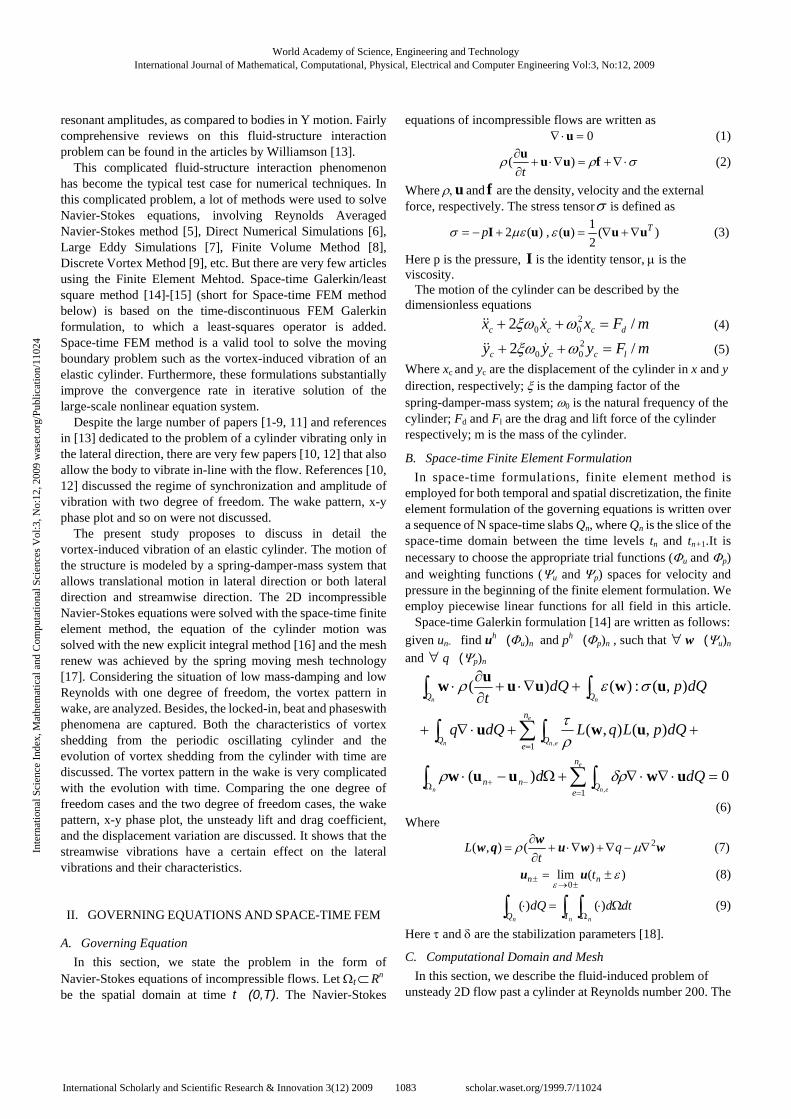
Navier-Stokes equations of incompressible flows. Let Ωt ⊂ Rn be the spatial domain at time t�(0,T). The Navier-Stokes
equations of incompressible flows are written as 0=⋅∇ u (1)
σρρ ⋅∇+=∇⋅+∂∂ fuuu
)(t
(2)
Where ρ, u and f are the density, velocity and the external force, respectively. The stress tensorσ is defined as
)(2 uI μεσ +−= p , )(2
1)( Tuuu ∇+∇=ε (3)
Here p is the pressure, I is the identity tensor, μ is the viscosity.
The motion of the cylinder can be described by the dimensionless equations
mFxxx dccc /2 200 =++ ωξω (4)
mFyyy lccc /2 200 =++ ωξω (5)
Where xc and yc are the displacement of the cylinder in x and y direction, respectively; ξ is the damping factor of the spring-damper-mass system; ω0 is the natural frequency of the cylinder; Fd and Fl are the drag and lift force of the cylinder respectively; m is the mass of the cylinder.
B. Space-time Finite Element Formulation In space-time formulations, finite element method is
employed for both temporal and spatial discretization, the finite element formulation of the governing equations is written over a sequence of N space-time slabs Qn, where Qn is the slice of the space-time domain between the time levels tn and tn+1.It is necessary to choose the appropriate trial functions (Φu and Φp) and weighting functions (Ψu and Ψp) spaces for velocity and pressure in the beginning of the finite element formulation. We employ piecewise linear functions for all field in this article.
Space-time Galerkin formulation [14] are written as follows:
given un-�find uh�(Φu)n and ph�(Φp)n , such that ∀ w�(Ψu)n
and ∀ q�(Ψp)n
0)(
),(),(
),(:)()(
1
1
,
,
=⋅∇⋅∇+Ω−⋅
++⋅∇+
+∇⋅+∂∂
⋅
∑∫∫
∑∫∫
∫∫
=Ω −+
=
e
enn
e
enn
nn
n
eQnn
n
eQQ
dQd
dQpLqLdQq
dQpdQt
uwuuw
uwu
uwuuuw
δρρ
ρτ
σερ
(6) Where
wwuwqw 2)(),( ∇−∇+∇⋅+∂∂
= μρ qt
L (7)
)(lim0
εε
±=±→
± nn tuu (8)
∫ ∫∫ ΩΩ⋅=⋅
n nn IQdtddQ )()( (9)
Here τ and δ are the stabilization parameters [18].
C. Computational Domain and Mesh In this section, we describe the fluid-induced problem of
unsteady 2D flow past a cylinder at Reynolds number 200. The
World Academy of Science, Engineering and TechnologyInternational Journal of Mathematical, Computational, Physical, Electrical and Computer Engineering Vol:3, No:12, 2009
1083International Scholarly and Scientific Research & Innovation 3(12) 2009 scholar.waset.org/1999.7/11024
Inte
rnat
iona
l Sci
ence
Ind
ex, M
athe
mat
ical
and
Com
puta
tiona
l Sci
ence
s V
ol:3
, No:
12, 2
009
was
et.o
rg/P
ublic
atio
n/11
024
30.5
16
8
8
D=1
x
y
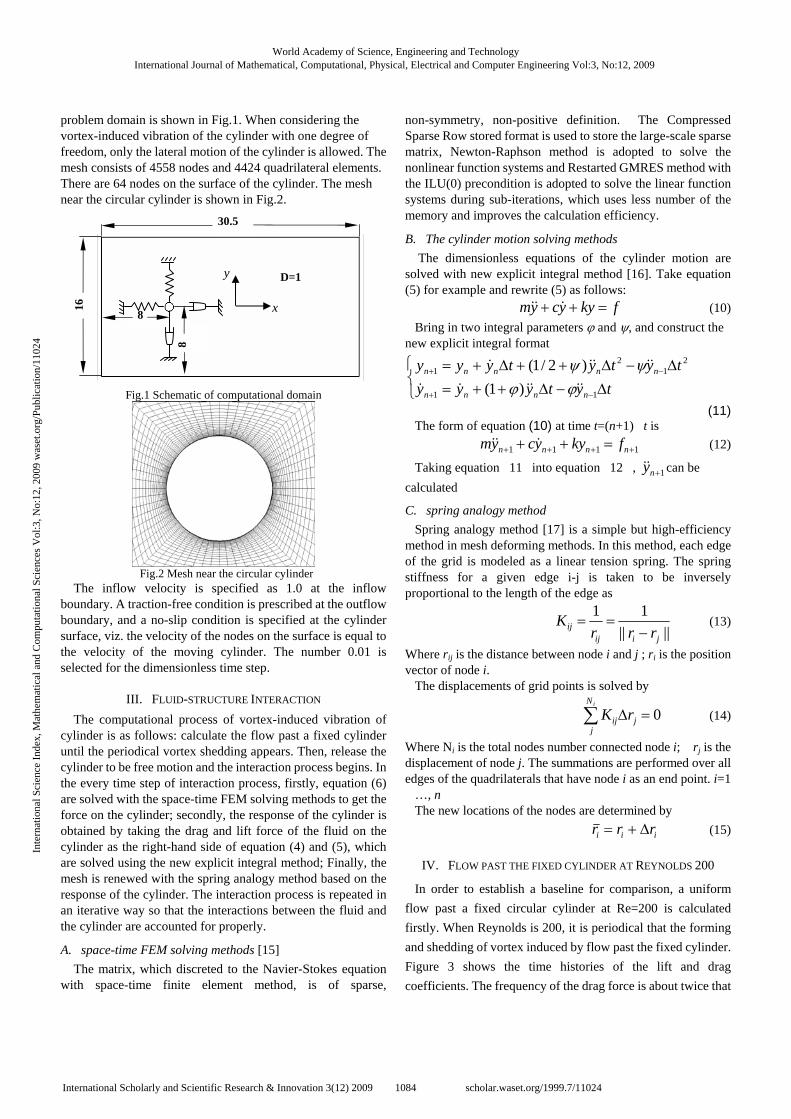
problem domain is shown in Fig.1. When considering the vortex-induced vibration of the cylinder with one degree of freedom, only the lateral motion of the cylinder is allowed. The mesh consists of 4558 nodes and 4424 quadrilateral elements. There are 64 nodes on the surface of the cylinder. The mesh near the circular cylinder is shown in Fig.2.
Fig.1 Schematic of computational domain
Fig.2 Mesh near the circular cylinder
The inflow velocity is specified as 1.0 at the inflow boundary. A traction-free condition is prescribed at the outflow boundary, and a no-slip condition is specified at the cylinder surface, viz. the velocity of the nodes on the surface is equal to the velocity of the moving cylinder. The number 0.01 is selected for the dimensionless time step.
III. FLUID-STRUCTURE INTERACTION
The computational process of vortex-induced vibration of cylinder is as follows: calculate the flow past a fixed cylinder until the periodical vortex shedding appears. Then, release the cylinder to be free motion and the interaction process begins. In the every time step of interaction process, firstly, equation (6) are solved with the space-time FEM solving methods to get the force on the cylinder; secondly, the response of the cylinder is obtained by taking the drag and lift force of the fluid on the cylinder as the right-hand side of equation (4) and (5), which are solved using the new explicit integral method; Finally, the mesh is renewed with the spring analogy method based on the response of the cylinder. The interaction process is repeated in an iterative way so that the interactions between the fluid and the cylinder are accounted for properly.
A. space-time FEM solving methods [15] The matrix, which discreted to the Navier-Stokes equation
with space-time finite element method, is of sparse,
non-symmetry, non-positive definition. The Compressed Sparse Row stored format is used to store the large-scale sparse matrix, Newton-Raphson method is adopted to solve the nonlinear function systems and Restarted GMRES method with the ILU(0) precondition is adopted to solve the linear function systems during sub-iterations, which uses less number of the memory and improves the calculation efficiency.
B. The cylinder motion solving methods The dimensionless equations of the cylinder motion are
solved with new explicit integral method [16]. Take equation (5) for example and rewrite (5) as follows:
fkyycym =++ (10)
Bring in two integral parameters ϕ and ψ, and construct the new explicit integral format
⎩⎨⎧
Δ−Δ++=Δ−Δ++Δ+=
−+
−+
tytyyytytytyyy
nnnn
nnnnn
11
21
21
)1(
)2/1(
ϕϕψψ
(11) The form of equation (10) at time t=(n+1)�t is
1111 ++++ =++ nnnn fkyycym (12)
Taking equation�11�into equation�12�, 1+ny can be
calculated�
C. spring analogy method Spring analogy method [17] is a simple but high-efficiency
method in mesh deforming methods. In this method, each edge of the grid is modeled as a linear tension spring. The spring stiffness for a given edge i-j is taken to be inversely proportional to the length of the edge as
||||
11
jiijij rrr
K−
== (13)
Where rij is the distance between node i and j ; ri is the position vector of node i.
The displacements of grid points is solved by
0=Δ∑iN
jjij rK (14)
Where Ni is the total nodes number connected node i; �rj is the displacement of node j. The summations are performed over all edges of the quadrilaterals that have node i as an end point. i=1�…, n�
The new locations of the nodes are determined by
iii rrr Δ+= (15)
IV. FLOW PAST THE FIXED CYLINDER AT REYNOLDS 200
In order to establish a baseline for comparison, a uniform
flow past a fixed circular cylinder at Re=200 is calculated
firstly. When Reynolds is 200, it is periodical that the forming
and shedding of vortex induced by flow past the fixed cylinder.
Figure 3 shows the time histories of the lift and drag
coefficients. The frequency of the drag force is about twice that
World Academy of Science, Engineering and TechnologyInternational Journal of Mathematical, Computational, Physical, Electrical and Computer Engineering Vol:3, No:12, 2009
1084International Scholarly and Scientific Research & Innovation 3(12) 2009 scholar.waset.org/1999.7/11024
Inte
rnat
iona
l Sci
ence
Ind
ex, M
athe
mat
ical
and
Com
puta
tiona
l Sci
ence
s V
ol:3
, No:
12, 2
009
was
et.o
rg/P
ublic
atio
n/11
024

of the lift force. Figure 4 shows a spectral analysis of the lift
coefficient curve. Obviously, the St is equal to 0.1972, which
means that the natural frequency of vortex shedding f0=0.1972.
The vortex mode in the wake of flow past a fixed cylinder is
shown in Figure 5. It composes of negative and positive
staggered vortices, which is the famous Karman vortex street.
Fig. 3 Lift and drag coefficients variations of flow past a cylinder
0.0 0.1 0.2 0.3 0.4 0.5 0.6 0.7 0.8 0.9 1.00.0
0.1
0.2
0.3
0.4
0.5
0.6
0.7
Frequency (Hz)
Am
plitu
de
Fig. 4 Spectral analysis of a fixed cylinder
Fig.5 vortex mode in the wake of flow past a fixed cylinder
V. VIV OF CYLINDER WITH ONE DEGREE OF FREEDOM
Generally speaking, vortex-induced vibration is of strongly non-linear quality. The vibration of structure influences the flow around cylinder, vice versa; the change of fluid influences the response of structure. The frequency ratio fn/f0 (fn represents the elastic cylinder natural frequency and f0 represents the vortex shedding frequency corresponding to the fixed cylinder) is a very important parameter, which influences the vortex induced vibration phenomena. Calculations are carried out for an elastic circular cylinder with one degree of lateral freedom for a number of cases where Re=200, dimensionless mass ratio M=1 and damping factor α=0.00306. The frequency ratio fn/f0
ranges from 0.5 to 2.5. Figure 6 shows the mean drag coefficient Cdmean, the r.m.s. of
lift coefficient Clrms, the average amptitude 2Yrms/D and phase difference φ at different frequency ratios. There are similar
trends between present computation and reference [9][10]. The amplitude of cylinder in lateral displacement reaches the maximum value when fn/f0=1.50. When the frequency ratio is between 0.9 and 1.0, the amplitude of lift coefficient reaches its minimum value. The phase between the lift force and the lateral displacement undergoes a suddenly change from 1500 to 200 .
Fig. 6 Main parameters versus frequency ratio
Figure 7 shows the lateral displacement and lift coefficient curves of an elastic circular cylinder with one degree of freedom. When the frequency ratio fn/f0 is small, i.e. fn/f0=0.5, the amplitude of lift coefficient of an elastic cylinder is larger than that of a fixed cylinder. The response of cylinder is very weak. With the increase of frequency ratio, the lateral displacement of the cylinder becomes larger, but the amplitude of lift coefficient becomes smaller. Besides, higher harmonics
World Academy of Science, Engineering and TechnologyInternational Journal of Mathematical, Computational, Physical, Electrical and Computer Engineering Vol:3, No:12, 2009
1085International Scholarly and Scientific Research & Innovation 3(12) 2009 scholar.waset.org/1999.7/11024
Inte
rnat
iona
l Sci
ence
Ind
ex, M
athe
mat
ical
and
Com
puta
tiona
l Sci
ence
s V
ol:3
, No:
12, 2
009
was
et.o
rg/P
ublic
atio
n/11
024
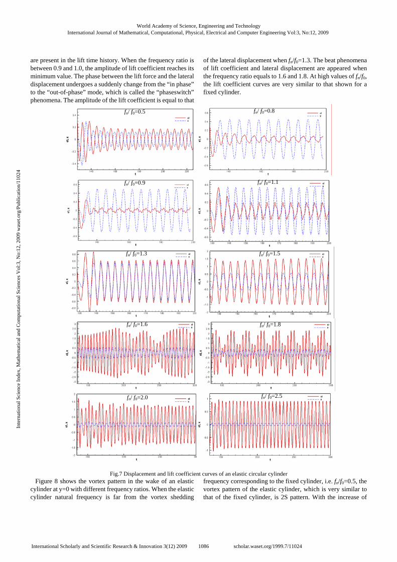
are present in the lift time history. When the frequency ratio is between 0.9 and 1.0, the amplitude of lift coefficient reaches its minimum value. The phase between the lift force and the lateral displacement undergoes a suddenly change from the “in phase” to the “out-of-phase” mode, which is called the “phaseswitch” phenomena. The amplitude of the lift coefficient is equal to that
of the lateral displacement when fn/f0=1.3. The beat phenomena of lift coefficient and lateral displacement are appeared when the frequency ratio equals to 1.6 and 1.8. At high values of fn/f0, the lift coefficient curves are very similar to that shown for a fixed cylinder.
Fig.7 Displacement and lift coefficient curves of an elastic circular cylinder Figure 8 shows the vortex pattern in the wake of an elastic
cylinder at y=0 with different frequency ratios. When the elastic cylinder natural frequency is far from the vortex shedding
frequency corresponding to the fixed cylinder, i.e. fn/f0=0.5, the vortex pattern of the elastic cylinder, which is very similar to that of the fixed cylinder, is 2S pattern. With the increase of
fn/ f0=2.5 fn/ f0=2.0
fn/ f0=1.8 fn/ f0=1.6
fn/ f0=1.5 fn/ f0=1.3
fn/ f0=1.1 fn/ f0=0.9
fn/ f0=0.8 fn/ f0=0.5
World Academy of Science, Engineering and TechnologyInternational Journal of Mathematical, Computational, Physical, Electrical and Computer Engineering Vol:3, No:12, 2009
1086International Scholarly and Scientific Research & Innovation 3(12) 2009 scholar.waset.org/1999.7/11024
Inte
rnat
iona
l Sci
ence
Ind
ex, M
athe
mat
ical
and
Com
puta
tiona
l Sci
ence
s V
ol:3
, No:
12, 2
009
was
et.o
rg/P
ublic
atio
n/11
024

frequency ratio, the lateral displacement of the cylinder becomes larger, which influences the vortex pattern in the wake. As shown in Figure 8(b), when fn/f0=0.9, the spacing in streamwise direction between vortices becomes smaller and two parallel rows with opposite sign of the vortices in the near wake appears, because of the increase of the vortex shedding frequency. The vortices spacing in streamwise direction becomes much smaller and the vortex in the wake is extruded by the vortices in neighborhoods at fn/f0=1.0. As shown in Figure 8(c), the extruded vortex decomposes of a main vortex and a sub vortex and in the wake there are different patterns at the different position in the wake, so it is a transition stage. When the frequency ratio is between 0.9 and 1.0, “phaseswitch” phenomena occurs and the pattern begins to change form 2S pattern to 2P pattern correspond. As the frequency ratio increases, when fn/f0=1.3 and fn/f0=1.5, as shown in Figure 8(e) and Figure 8(f) respectively, the
amplitude of motion reaches the maximum peak. The vortex shedding from the cylinder decomposes of a main vortex and a sub vortex because of extrusion, and there are two lines of sub vortices besides two lines of main vortices. Besides, two lines vortices extrude each other in the lateral direction and the amplitude of motion reaches the maximum peak, that is the reason there are alternative vortices appeared in the lateral spacing between two lines of main vortices. With the evolution of the vortices, the middle vortices are gradually merged into the two lines of main vortices in the far wake. As the beat phenomena of lift coefficient and lateral displacement are appeared when the frequency ratio equals to 1.6, the vortex pattern is complex. The pattern is different with different amplitude of cylinder motion, as shown in Figure 8(g). When the frequency ratio fn/f0 is large, i.e. fn/f0=2.5, the vortex pattern of the elastic cylinder, which is very similar to that of the fixed cylinder, is the standard Karman vortex street.
Fig. 8 Vortex pattern in the wake of an elastic cylinder with different frequency ratios
VI. VIV OF CYLINDER WITH TWO DEGREE OF FREEDOM
Finally, a two degree of freedom case with Re=200, M=1 and α=0.00306, where the cylinder is allowed to vibrate in both lateral direction and stream-wise direction, is calculated and the results are compared with those if the one degree of freedom case. The frequency ratio fn/f0 ranges from 0.5 to 3.0. The comparison of the drag coefficient, the r.m.s. of the coefficient, the r.m.s. of the lift coefficient, the r.m.s of the lateral displacement and the ratio of vortex shedding frequency and natural frequency are shown in Figure 9,10,11,12 and 13, respectively. In these figures, the circular and square symbols represent the results of the two degree of freedom case and the one degree of freedom case respectively.
It is seen that main parameters for the two cases are almost consistent. The drag coefficients for the two cases are almost
equal. The r.m.s of drag coefficient shows a very similar behavior, which appears to have a higher value for one degree of freedom case than for the two degree of freedom case. Oppositely, the r.m.s of lateral displacement appears to have a higher value for two degree of freedom case than for the one degree of freedom case. Figure 14 shows the mean streamwise displacement at the different frequency ratios. With the increment of frequency ratio, the mean streamwise displacement becomes smaller. It is very interesting that the mean streamwise displacement is not proportional to the mean drag coefficient.
(a) =0/ ffn 0.5 (b) =0/ ffn 0.9
(c) =0/ ffn 1.0 (d) =0/ ffn 1.1
(e) =0/ ffn 1.3 (f) =0/ ffn 1.5
(g) =0/ ffn 1.6 (h) =0/ ffn 2.5
World Academy of Science, Engineering and TechnologyInternational Journal of Mathematical, Computational, Physical, Electrical and Computer Engineering Vol:3, No:12, 2009
1087International Scholarly and Scientific Research & Innovation 3(12) 2009 scholar.waset.org/1999.7/11024
Inte
rnat
iona
l Sci
ence
Ind
ex, M
athe
mat
ical
and
Com
puta
tiona
l Sci
ence
s V
ol:3
, No:
12, 2
009
was
et.o
rg/P
ublic
atio
n/11
024

0.0 0.5 1.0 1.5 2.0 2.5 3.0
1.2
1.4
1.6
1.8
2.0
2.2
2.4
fn/f0
Cd
1DOF 2DOF
0.0 0.5 1.0 1.5 2.0 2.5 3.0
0.0
0.2
0.4
0.6
0.8
1.0
fn/f0
Cd rm
s
1DOF 2DOF
Fig. 9 Comparison of the mean drag coefficient Fig.10 Comparison of the r.m.s. of the drag coefficient
0.0 0.5 1.0 1.5 2.0 2.5 3.0
0.0
0.2
0.4
0.6
0.8
1.0
1.2
1.4
1.6
fn/f0
Cl rm
s
1DOF 2DOF
0.0 0.5 1.0 1.5 2.0 2.5 3.00.0
0.2
0.4
0.6
0.8
1.0
fn/f0
2Yrm
s/D
1DOF 2DOF
Fig.11 Comparison of the r.m.s. of the lift coefficient Fig. 12 Comparison of the r.m.s. of y-displacement
0.0 0.5 1.0 1.5 2.0 2.5 3.00.6
0.8
1.0
1.2
1.4
fn/f0
f s/f0
1DOF 2DOF
0.0 0.5 1.0 1.5 2.0 2.5 3.0
0.0
0.2
0.4
0.6
0.8
1.0
1.2
1.4
1.6
fn/f0
Xm
ean
2DOF
Fig.13 Comparison of the frequency ratio fs/f0 Fig.14 The mean streamwise displacement
Figure 15 shows the X-Y phase plot for two degree of
freedom of an elastic cylinder. It is seen that with the increment of frequency ratio, the equilibrium position of the vibration in the streamwise direction becomes smaller, besides, the lateral amplitude increase firstly and then decrease. When the frequency ratios are 1.5 and 1.6, the X-Y phase is very complex. That’s because beat phenomena occurs at that frequency ratios.
Figure 16 shows vortex pattern in the wake of an elastic cylinder with two degree of freedom at different frequency
ratios. Compared to figure 6, there are two obvious differences as follows: (1) The vortex pattern at fn/f0=1.5 is different from that with
one degree of freedom because of the beat phenomenon as shown in Figure 16(g).
(2) When fn/f0=1.3 and fn/f0=1.4, as shown in Figure 16(e) and Figure 16(f) respectively, the amplitude of motion reaches
World Academy of Science, Engineering and TechnologyInternational Journal of Mathematical, Computational, Physical, Electrical and Computer Engineering Vol:3, No:12, 2009
1088International Scholarly and Scientific Research & Innovation 3(12) 2009 scholar.waset.org/1999.7/11024
Inte
rnat
iona
l Sci
ence
Ind
ex, M
athe
mat
ical
and
Com
puta
tiona
l Sci
ence
s V
ol:3
, No:
12, 2
009
was
et.o
rg/P
ublic
atio
n/11
024

Fig.15 X-Y phase plot for two degree of freedom of an elastic cylinder
Fig. 16 Vortex pattern in the wake of an elastic cylinder with two degree of freedom
fn/ f0=0.5
fn/ f0=1.5
fn/ f0=0.9 fn/ f0=1.0
fn/ f0=1.1 fn/ f0=1.3 fn/ f0=1.4
fn/ f0=1.6 fn/ f0=2.5
(a) =0/ ffn 0.5 (b) =0/ ffn 0.9
(c) =0/ ffn 1.0 (d) =0/ ffn 1.1
(e) =0/ ffn 1.3
(g) =0/ ffn 1.5
(f) =0/ ffn 1.4
(h) =0/ ffn 3.0
World Academy of Science, Engineering and TechnologyInternational Journal of Mathematical, Computational, Physical, Electrical and Computer Engineering Vol:3, No:12, 2009
1089International Scholarly and Scientific Research & Innovation 3(12) 2009 scholar.waset.org/1999.7/11024
Inte
rnat
iona
l Sci
ence
Ind
ex, M
athe
mat
ical
and
Com
puta
tiona
l Sci
ence
s V
ol:3
, No:
12, 2
009
was
et.o
rg/P
ublic
atio
n/11
024

Fig.17 Displacement and lift coefficient curves of an elastic circular cylinder with two degree of freedom
the maximum peak. Two lines vortices extrude each other in the lateral direction and the amplitude of motion reaches the maximum peak. There are alternative vortices pairs appeared in
the lateral spacing between two lines of main vortices in the near wake, different from the pattern for the one degree of freedom case.
fn/ f0=1.1
fn/ f0=0.5 fn/ f0=0.8
fn/ f0=0.9
fn/ f0=1.3 fn/ f0=1.5
fn/ f0=1.6 fn/ f0=1.8
fn/ f0=2.0 fn/ f0=2.5
World Academy of Science, Engineering and TechnologyInternational Journal of Mathematical, Computational, Physical, Electrical and Computer Engineering Vol:3, No:12, 2009
1090International Scholarly and Scientific Research & Innovation 3(12) 2009 scholar.waset.org/1999.7/11024
Inte
rnat
iona
l Sci
ence
Ind
ex, M
athe
mat
ical
and
Com
puta
tiona
l Sci
ence
s V
ol:3
, No:
12, 2
009
was
et.o
rg/P
ublic
atio
n/11
024

Figure 17 shows the displacement and lift coefficient curves of an elastic circular cylinder with two degree of freedom at different frequency ratios. Compared to figure 6 for one degree of freedom, there is no obvious difference. The only difference is that the beat phenomena occurs at the frequency ratio fn/f0 =1.5 for the two degree of freedom case, while the beat phenomena occurs at the frequency ratio fn/f0 =1.6 for the one degree of freedom case. When the elastic cylinder natural frequency is far from the vortex shedding frequency corresponding to the fixed cylinder, i.e. fn/f0=0.5, the lateral response of cylinder is very weak, but the equilibrium position of the streamwise vibration is very large. With the increase of frequency ratio, the lateral displacement of the cylinder becomes larger and the streamwise displacement becomes smaller. When the frequency ratio is between 0.9 and 1.0, the amplitude of lift coefficient reaches its minimum value and the “phaseswitch” phenomenon occurs. The beat phenomena of lift coefficient and lateral displacement are appeared when the frequency ratio equals to 1.5, 1.6 and 1.8. At high values of fn/f0, the response of the cylinder is very weak.
VII. CONCLUSION
A numerical simulation of vortex-induced vibration of a 2-dimensional elastic circular cylinder is carried out using the Space-time FEM. There are several conclusions:
(1) The calculation of the fluid-structure problem is achieved by the combination of using the space-time finite element method, the new explicit integral method and spring moving mesh technology.
(2) The variety trend of the lift coefficient, the drag coefficient, the displacement of cylinder was analyzed under different oscillating frequencies of cylinder. The phenomena of locked-in, beat and phases-witch were captured successfully.
(3) Comparing the two cases, it shows that the streamwise vibrations have a certain effect on the lateral vibrations and their characteristics.
ACKNOWLEDGMENT
This work was supported by 973 Program (No.2007CB714701), National Natural Science Foundation of China (No. 50821063, No.50823004).
REFERENCES [1] P. Anagnostopoulos, P.W. Bearman, “Response characteristics of a
vortex-excited cylinder at low Reynolds number,” J. luids.Struct., vol. 6, pp. 39–50, 1992.
[2] A. Khalak, C.H.K. Williamson, “Investigation of the realative effects of mass and damping in vortex-induced vibration of a circular cylinder”, J. Wind Eng. Ind. Aerodyn. vol. 69-71, pp. 341–350, 1997.
[3] D. Brika, A. Laneville, “Vortex-induced vibrations of a long flexible circular cylinder”, J. Fluid Mech. vol. 250, pp. 481–508, 1993.
[4] C.H.K. Williamson, A. Roshko, “Vortex formation in the wake of an
oscillating cylinder”, J. Fluids Struct. vol. 2, pp. 355-381, 1988. [5] E. Guilmineau, P. Queutey, “Numerical simulation of vortex-induced
vibration of a circular cylinder with low mass-damping in a turbulent
flow”, J. Fluids Struct. vol. 19, pp. 449-466, 2004. [6] S. Dong, G.E. Lesoinne, “DNS of flow past a stationary and oscillating
cylinder at Re=10000”, J. Fluids Struct. vol. 20, pp. 519-531, 2005. [7] H. Al-Jamal, C. Dalton, “vortex induced vibrations using large eddy
simulation at a moderate Reynolds number”, J. Fluids Struct. vol. 19, pp. 73-92, 2004.
[8] A. Placzek, J.F. Sigrist, A.Hamdouni, “Numerical simulation of an oscillating cylinder in a cross-flow at low Reynolds number: Forced and free oscillations”, Comuter&fluids. vol. 38, pp. 80-100, 2009.
[9] C.Y.Zhou, C.Sorm, K.Lam, “vortex induced vibrations of an elastic
circular cylinder”, J. Fluids Struct. vol. 13, pp. 165-189, 1999. [10] G.W. Li, A.L. Ren, W.Q. Chen, “An ALE method for vortex-induced
vibrations of an elastic circular cylinder”, Acta.Aerodynamic.Asinica. vol. 22, pp. 283-288, 2004.
[11] J.R. Meneghini, P.W. Bearman, “Numerical simulation of high amplitude
oscillatory flow about a circular cylinder”, J. Fluids Struct. vol. 9, pp. 435-455, 1995.
[12] T.Sarkaya, “Hydrodynamic damping, flow-induced oscillations, and biharmonic response”, ASME J.Offshore Mech. Arctic Eng. vol. 117, pp. 232-238, 1995.
[13] C.H.K. Williamson, R. Govardhan, “Vortex-induced vibration”. Annu. Rev. Fluid Mech. vol. 36, pp. 413-455, 2004.
[14] T.E.Tezduyar , S.Mittal and S.E.Ray, “Incompressible flow computations with bilinear and linear equal-order-interpolation velocity-pressure elements”, Comp. Meth. App. Mech.&Eng., vol. 95, pp 221-242, 1992.
[15] T. Li, J.Y. Zhang, W.H. Zhang. “Efficient evaluation of space-time finite element method”, Journal of Southwest Jiaotong Unversity, vol. 43. pp 772-777. 2008
[16] W.M. Zhai, Vehicle-track coupling dynamics. Beijing: China Railway publishing house, 2001, pp 397-399.
[17] M. Mistsuhiro, N.Kazuhiro, M. Kisa, “Unstructured dynamic mesh for large movement and deformation”, AIAA, vol. 40. pp 1-11. 2002
[18] L.P. Franca, S.L. Frey, “Stabilized finite element method: II. The incompressible Navier-Stokes equations”, Comp. Meth. App. Mech. & Eng., vol. 99. pp 209-233. 1992.
World Academy of Science, Engineering and TechnologyInternational Journal of Mathematical, Computational, Physical, Electrical and Computer Engineering Vol:3, No:12, 2009
1091International Scholarly and Scientific Research & Innovation 3(12) 2009 scholar.waset.org/1999.7/11024
Inte
rnat
iona
l Sci
ence
Ind
ex, M
athe
mat
ical
and
Com
puta
tiona
l Sci
ence
s V
ol:3
, No:
12, 2
009
was
et.o
rg/P
ublic
atio
n/11
024


