
Volumetric reconstruction of particulate dispersions from...
9
17 th International Symposium on Applications of Laser Techniques to Fluid Mechanics Lisbon, Portugal, 07-10 July, 2014 - 1 - Volumetric reconstruction of particulate dispersions from a light field image by means of a plenoptic camera Tatsuya KAWAGUCHI*, Takushi SAITO and Isao SATOH Department of mechanical and control engineering, Tokyo institute of technology Ookayama 2-12-1, Meguro-ku, Tokyo 152-8552, Japan * correspondent author: [email protected] Abstract Volumetric reconstruction of the particulate field is one of the significant and desired technique for the understanding of the fluid phenomena. Since the various kinds of the whole-field technique such as stereo-PIV, multilayer-PIV, Holo- and Tomo-PIV have been developed, the measurement system or optical set-up tend to be complicated. In this study, the 4D light field camera was applied to the measurement of the three dimensional particulate field. The camera could record not only the position of the scatted ray from a particles but also the angle of the rays instantaneously. The entire information of the ray enables to reconstruct the volumetric image of the particle field. The light field imaging technique was firstly applied to the multi-layer PIV measurement that is followed by the volumetric reconstruction of the particle images by means of the multiplicative algebraic reconstruction technique. 1. Introduction Instantaneous volumetric recording of the dispersed particulate field is desired in order to understand the flow field by means of the field fluid measurement techniques such as particle image velocimetry (PIV) (Adrian 1981) and droplet sizing for the spray applications as well. Multi-layer PIV and the stereoscopic PIV (Arroyo 1991) were the direct extension of the conventional 2D2C PIV that enabled to obtain three- dimensional and third velocity component respectively. Holo-PIV (Hirsch 2002) is the optical method that captures the depth information of the particle locations, the method however has difficulty in recording the successive images. Tomo-PIV (Elsinga 2006) is the recently developed 3D3C velocimetry technique that employs the multiple cameras in conjunction with the algebraic reconstruction technique for the determination of the three dimensional particulate field. These multi-camera methodologies assume that the scattered ray from the tracer particles is isotropic which is known as a Lambert redundancy. Moreover the scattered ray from a particle was recorded by the multiple cameras in order to recover the depth information of the particles that was lost by the planar sensors. Recently, the 4D light field camera, which is also called a plenoptic camera or integral photograph that employ the two-dimensional microlens array in the vicinity of the sensor (Ren 2005). Original idea of the camera was introduced by Lippmann (1908), the fabrication technology of optical microlens, however, was not present at that time. Vaish (2004) employed the light field imaging system by attaching external lens array in front of main lens of normal digital camera. Georgiev (2003) captured a light field imaging by making the camera array which displayed a lot of camera itself. The recent light field camera could capture the image from the multiple angle of view with only one camera, instead of the multiple pair of the sensor and lens. In other words, an image acquisition by the light field camera is equivalent to the recording by the multiple cameras. Another significant advantage of the camera is that the focal plane could be adjusted as the post processing by the computer, which enables to refocus the particles after the image acquisition, i.e. the volumetric particulate field is reconstructed for the PIV or spray diagnostics (Cenedese 2012, Techet 2012). The reconstructed volume information, however, suffered from the undesired ghost image due to the linear back-projection procedure. In this study, the simplified anti-hexagonal filter as well as the multiplicative algebraic reconstruction technique was employed in order to reconstruct the volumetric particle images that well contribute to the whole-field, time-resolved and single-camera particle image velocimetry.
Transcript of Volumetric reconstruction of particulate dispersions from...
17th International Symposium on Applications of Laser Techniques to Fluid Mechanics Lisbon, Portugal, 07-10 July, 2014
- 1 -
Volumetric reconstruction of particulate dispersions
from a light field image by means of a plenoptic camera
Tatsuya KAWAGUCHI*, Takushi SAITO and Isao SATOH
Department of mechanical and control engineering, Tokyo institute of technology
Ookayama 2-12-1, Meguro-ku, Tokyo 152-8552, Japan
* correspondent author: [email protected] Abstract Volumetric reconstruction of the particulate field is one of the significant and desired technique for the understanding of the fluid phenomena. Since the various kinds of the whole-field technique such as stereo-PIV, multilayer-PIV, Holo- and Tomo-PIV have been developed, the measurement system or optical set-up tend to be complicated. In this study, the 4D light field camera was applied to the measurement of the three dimensional particulate field. The camera could record not only the position of the scatted ray from a particles but also the angle of the rays instantaneously. The entire information of the ray enables to reconstruct the volumetric image of the particle field. The light field imaging technique was firstly applied to the multi-layer PIV measurement that is followed by the volumetric reconstruction of the particle images by means of the multiplicative algebraic reconstruction technique. 1. Introduction Instantaneous volumetric recording of the dispersed particulate field is desired in order to understand the flow field by means of the field fluid measurement techniques such as particle image velocimetry (PIV) (Adrian 1981) and droplet sizing for the spray applications as well. Multi-layer PIV and the stereoscopic PIV (Arroyo 1991) were the direct extension of the conventional 2D2C PIV that enabled to obtain three-dimensional and third velocity component respectively. Holo-PIV (Hirsch 2002) is the optical method that captures the depth information of the particle locations, the method however has difficulty in recording the successive images. Tomo-PIV (Elsinga 2006) is the recently developed 3D3C velocimetry technique that employs the multiple cameras in conjunction with the algebraic reconstruction technique for the determination of the three dimensional particulate field. These multi-camera methodologies assume that the scattered ray from the tracer particles is isotropic which is known as a Lambert redundancy. Moreover the scattered ray from a particle was recorded by the multiple cameras in order to recover the depth information of the particles that was lost by the planar sensors. Recently, the 4D light field camera, which is also called a plenoptic camera or integral photograph that employ the two-dimensional microlens array in the vicinity of the sensor (Ren 2005). Original idea of the camera was introduced by Lippmann (1908), the fabrication technology of optical microlens, however, was not present at that time. Vaish (2004) employed the light field imaging system by attaching external lens array in front of main lens of normal digital camera. Georgiev (2003) captured a light field imaging by making the camera array which displayed a lot of camera itself. The recent light field camera could capture the image from the multiple angle of view with only one camera, instead of the multiple pair of the sensor and lens. In other words, an image acquisition by the light field camera is equivalent to the recording by the multiple cameras. Another significant advantage of the camera is that the focal plane could be adjusted as the post processing by the computer, which enables to refocus the particles after the image acquisition, i.e. the volumetric particulate field is reconstructed for the PIV or spray diagnostics (Cenedese 2012, Techet 2012). The reconstructed volume information, however, suffered from the undesired ghost image due to the linear back-projection procedure. In this study, the simplified anti-hexagonal filter as well as the multiplicative algebraic reconstruction technique was employed in order to reconstruct the volumetric particle images that well contribute to the whole-field, time-resolved and single-camera particle image velocimetry.

17th International Symposium on Applications of Laser Techniques to Fluid Mechanics Lisbon, Portugal, 07-10 July, 2014
- 2 -
2. 4D Light field imaging by means of a plenoptic camera The scatted rays such as the Mie scattering from dispersed phase in the fluid flow consist of the multiple rays in terms of the angle and position of the origin of the ray. The ray is a function of the two dimensional relative position and two components relative angles to the optical axis of the receiving optics. Figure 1 depicted the fundamental coordinated of the light field. The ray scattered from a particle is consisted of the four independent components, relative position, q, and angle, p, to the optical axis of the receiving optics. The recent light field camera employs plenoptic 2.0 alignments of the optical elements (Georgiev 2009, 2010, Lumsdaine 2009). Figure 2 shows the fundamental alignment of the optical elements by plenoptic 2.0 system. The alignment has the better spatial resolution than that of the plenoptic 1.0 configuration. In order to evaluate the effective spatial resolution of plenoptic camera, which enables to record not only the 2D position of object but also the 2D angle of ray, the rays through the plenoptic optics, was numerically investigated by means of geometrical optics. Figure 3 and figure 4 compare the scattered rays from two independent particles with 30 µm separation through the plenoptic 1.0 and 2.0 system. Recent development of high-resolution digital CMOS sensor as well as the fabrication technique of high density micro-lens matrix enables us to capture the many sub-images with the different angle of view in the single instantaneous image. Since the plenoptic camera could capture not only the planar image but also the different angle of view of the physical object, the focused plane could be adjusted after the image acquisition. In this study, the effective spatial resolution of light field image in terms of the various optical parameters was analyzed in order to apply the camera to the measurement of the dispersed particles. Figure 5 is the numerically reconstructed synthetic particle images from the single light field image. The different depth focal plane, z=1mm and z=-1mm was compared. Though the defocused particles were appeared in the both images, the intensity of the in-focus particles is much higher than that of the out-of-focus particles. Since the diameter of the in-focus particles is much smaller, the higher spatial frequency components of in-focus particles significantly contribute to the cross correlation coefficients for the interrogation of the particle image velocimetry.
Figure 1. Coordinates of 4D light field. q1, q2 and p1, p2 represent two dimensional position and angles of ray
respectively.

17th International Symposium on Applications of Laser Techniques to Fluid Mechanics Lisbon, Portugal, 07-10 July, 2014
- 3 -
Image planeMain lens Lensarray
Sensor
Figure 2. Simplified optical alignment of plenoptic 2.0 optics.
Plenoptic 1.0
z (m)
q1 (m) Size of microlens(100 µm)
Figure 3. Detailed rays from two neighboring particles. The rays in the vicinity of the microlens array were depicted. Plenoptic 1.0 optics is used. Different particle images were exposed at the exactly same position on a sensor by which the angle of ray is obtained by the sensor pixel.

17th International Symposium on Applications of Laser Techniques to Fluid Mechanics Lisbon, Portugal, 07-10 July, 2014
- 4 -
Plenoptic 2.0(Keplerien)
z (m)
q1 (m)
Figure 4. Optical arrangement of plenoptic 2.0 light field camera. The micro lens array is located behind the focal point of a main lens. The sensor is focused on a virtual imaging plane by micro lens array. Detailed rays from two particles in the vicinity of the microlens array and sensor were depicted. On the sensor, two independent particle could be distinguished.
z = +1mm z = -1 mm Figure 5. The synthetic images of two parallel planes by refocusing post processing. Actual pixel number of synthetic images was 1250x1250, only 256x256 sub-areas were depicted. 3. Simultaneous acquisition of multi-layer particle image
Figure 6 illustrates the experimental setup for the volumetric image acquisition of the particle images that consisted of a light source, plenoptic camera and main lens. Nd:YLF laser was used as a light source of the laser sheets. The wavelength and output power were 527 nm and 10 W respectively. Dual plane laser sheet

17th International Symposium on Applications of Laser Techniques to Fluid Mechanics Lisbon, Portugal, 07-10 July, 2014
- 5 -
with 8 mm separation was used. Each sheet was 4 mm of thickness. Raytrix R5 Camera was used that is connected to the PC via gigabit ether connection. Original pixel number of the camera was 2048x2048 pixel. The size of the synthetic image was 1024x1024. Frame rate of the camera was 25 frames per sec, area of view was 22mm x 22 mm due to the magnification ratio of the main lens we used. Nikon 85mm f1.8 lens was used as the main lens. Tap water was used as a working fluid. Transient flow was induced by the solid stick. Polystyrene spherical particle was dispersed as a tracer particle. The arithmetic mean diameter of the particle was 50 µm. Laptop PC with Intel Core i7 3GHz 8core + NVIDIA GTX480M GPGPU (general-purpose computing on graphics processing units) was employed in order to capture the light field image and compute the synthetic image and PIV calculation as well. The cross correlation computation with a Gaussian subpixel interpolation was performed by means of a portable workstation. Resultant in-plane spatial resolution of the measured velocity was 2 mm with the 50% overlapping window methodology of PIV image processing. Figure 7 depicts the instantaneous captured light field image of the tracer particles and their magnified image. Rays scattered from the single particle passed through the different microlens, and reached to the different CMOS sensors in terms of the angle of the rays. The spatio-angular information recorded in the instantaneous light field image enables us to reconstruct the particle images at the different focal planes by the image processing. Figure 8 compare the multi-layer velocity vector map at the different depth plane. Particle images at both planes were reconstructed from the single light field image by using the standard RxLive software by Raytrix. The result demonstrated that the velocity vector field in the multiple depth layers could be obtained simultaneously by a light field camera. Although both synthetic images contains the undesired defocused particle images, the band-cut notch filter enables to calculate the cross correlation functions without the characteristic cyclic hexagonal patterns. The impact of the defocused particle image, however, affects the resultant accuracy of velocity determination, further detailed investigation is necessary. The technique led us to the determination of the third components of the velocity by using a voxel correlation between synthetic images from the light field camera.
Figure 6. Experimental setup. Physical dimension of the test section was 22 mm x 22 mm, laser sheet thickness and
separation was 4 mm and 8 mm respectively.

17th International Symposium on Applications of Laser Techniques to Fluid Mechanics Lisbon, Portugal, 07-10 July, 2014
- 6 -
(original) (magnified)
Figure 7. Instantaneous light field image. Left image is the original output from the CMOS sensor, right image is the magnified light field image. Each circular cell corresponds the sub-image due to the microlens array. Rays from the
single particle were exposed on the different sensors due to the microlens array.
z = +4 mm z = -4 mm
Figure 8. Velocity vector map at the different depth plane (z axis) at the same instance. These two particle images were generated from an instantaneous light field image as shown in figure 7.
4. Volume reconstruction of three dimensional particulate field In order to reconstruct a volumetric intensity field for particle image velocimetry, one simple methodology is the direct back projection of the captured rays into a reconstructed volume. The back projection, however
17th International Symposium on Applications of Laser Techniques to Fluid Mechanics Lisbon, Portugal, 07-10 July, 2014
- 7 -
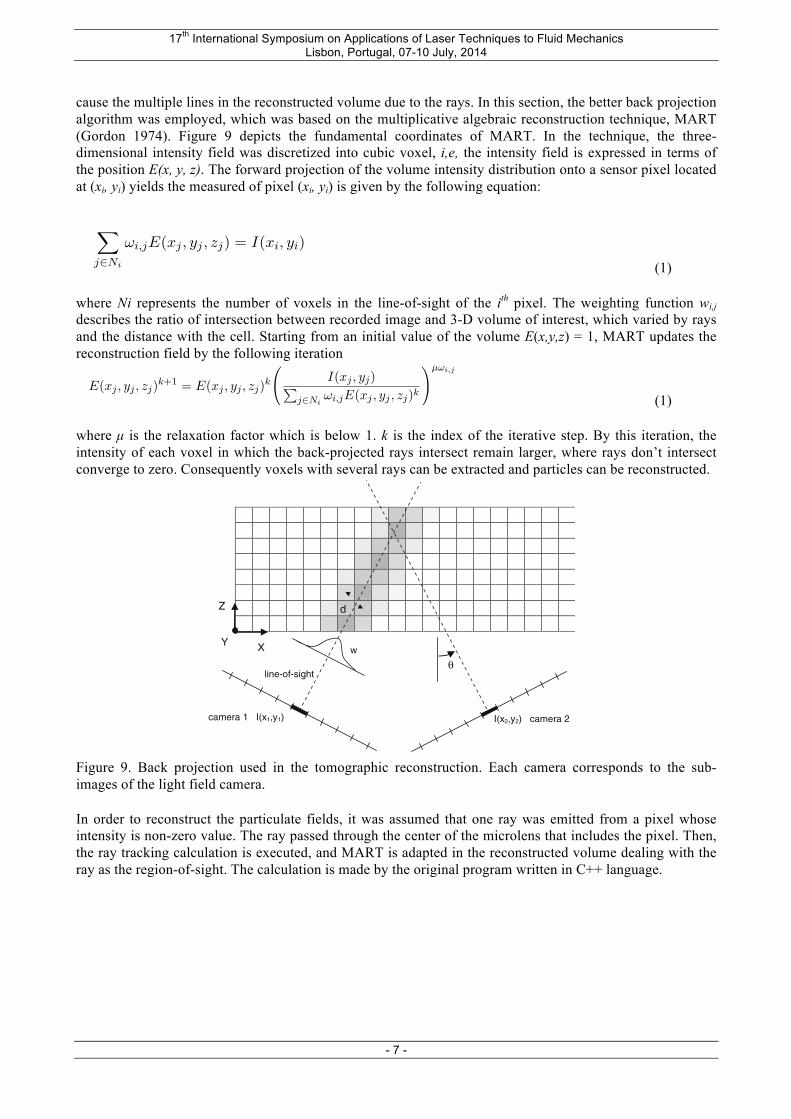
cause the multiple lines in the reconstructed volume due to the rays. In this section, the better back projection algorithm was employed, which was based on the multiplicative algebraic reconstruction technique, MART (Gordon 1974). Figure 9 depicts the fundamental coordinates of MART. In the technique, the three-dimensional intensity field was discretized into cubic voxel, i,e, the intensity field is expressed in terms of the position E(x, y, z). The forward projection of the volume intensity distribution onto a sensor pixel located at (xi, yi) yields the measured of pixel (xi, yi) is given by the following equation:
第 4章 光線の逆追跡による再構成のシミュレーション
(a) z=0mm (b) z=+1.0mm
Figure 4.8: Raw image of a particle generated by ray-trace simulation.
えていく.このセルに与える輝度値は式 (4.1)に示される様な関係を満たす.
!
j∈Ni
ωi,jE(xj , yj , zj) = I(xi, yi) (4.1)
ここでNiは一本の光線に対する輝度を与えるセルの数,E(xj , yj , zj)はNi個のセルのう
ちの j 番目のセルの輝度値,I(xi, yi)は画像の i番目のピクセルの輝度値を示す.ωi,j は重
み関数であり,光線とセルとの距離によって変化する.このように与えていったセルの輝度
値を式 (4.2)に示される MART と呼ばれるアルゴリズムを用いて値を更新していくことに
より,光線の交わる部分のセルの輝度値は大きく,交わらない部分のセルの輝度値は小さく
なっていく.これにより,光線の交わる位置,すなわち粒子の位置のみを残し,その他の部
分を除去することが出来る.
E(xj , yj , zj)k+1 = E(xj , yj , zj)k
"I(xj , yj)#
j∈Niωi,jE(xj , yj , zj)k
$µωi,j
(4.2)
µは緩和係数とよばれ,0から 1の間で任意に定める.kは更新の繰り返し回数を示す.良
好な結果を得る為に,この µや kを適切に定める必要がある.
第 4.2節のような光線追跡を一度行い,センサに露光した画像を作成した後,上記のMART
を適応することによって粒子の再構成を行った,その結果をFigure 4.10からFigure 4.12に
示す.Figure 4.10は斜め上から見た図,Figure 4.11は正面から見た図,Figure 4.12は上か
Department of Mechanical and Intelligent Systems Engineering,Tokyo Institute of Technology
30
(1) where Ni represents the number of voxels in the line-of-sight of the ith pixel. The weighting function wi,j describes the ratio of intersection between recorded image and 3-D volume of interest, which varied by rays and the distance with the cell. Starting from an initial value of the volume E(x,y,z) = 1, MART updates the reconstruction field by the following iteration
第 4章 光線の逆追跡による再構成のシミュレーション
(a) z=0mm (b) z=+1.0mm
Figure 4.8: Raw image of a particle generated by ray-trace simulation.
えていく.このセルに与える輝度値は式 (4.1)に示される様な関係を満たす.
!
j∈Ni
ωi,jE(xj , yj , zj) = I(xi, yi) (4.1)
ここでNiは一本の光線に対する輝度を与えるセルの数,E(xj , yj , zj)はNi個のセルのう
ちの j 番目のセルの輝度値,I(xi, yi)は画像の i番目のピクセルの輝度値を示す.ωi,j は重
み関数であり,光線とセルとの距離によって変化する.このように与えていったセルの輝度
値を式 (4.2)に示される MART と呼ばれるアルゴリズムを用いて値を更新していくことに
より,光線の交わる部分のセルの輝度値は大きく,交わらない部分のセルの輝度値は小さく
なっていく.これにより,光線の交わる位置,すなわち粒子の位置のみを残し,その他の部
分を除去することが出来る.
E(xj , yj , zj)k+1 = E(xj , yj , zj)k
"I(xj , yj)#
j∈Niωi,jE(xj , yj , zj)k
$µωi,j
(4.2)
µは緩和係数とよばれ,0から 1の間で任意に定める.kは更新の繰り返し回数を示す.良
好な結果を得る為に,この µや kを適切に定める必要がある.
第 4.2節のような光線追跡を一度行い,センサに露光した画像を作成した後,上記のMART
を適応することによって粒子の再構成を行った,その結果をFigure 4.10からFigure 4.12に
示す.Figure 4.10は斜め上から見た図,Figure 4.11は正面から見た図,Figure 4.12は上か
Department of Mechanical and Intelligent Systems Engineering,Tokyo Institute of Technology
30
(1) where µ is the relaxation factor which is below 1. k is the index of the iterative step. By this iteration, the intensity of each voxel in which the back-projected rays intersect remain larger, where rays don’t intersect converge to zero. Consequently voxels with several rays can be extracted and particles can be reconstructed.
beyond the scope of the present study and can befound in Herman and Lent (1976). Instead the per-formance of two different tomographic algorithms isevaluated by numerical simulations of a tomographic-PIV experiment focusing the evaluation upon thereconstruction accuracy and convergence properties.The comparison is performed between the additive andmultiplicative techniques referred to as ART (alge-braic reconstruction technique) and MART (multipli-cative algebraic reconstruction technique), respectively(Herman and Lent 1976). Starting from a suitable ini-tial guess (E(X, Y, Z)0 is uniform, see next section) theobject E(X, Y, Z) is updated in each full iteration as:
1. for each pixel in each camera i:2. for each voxel j:
ART: EðXj;Yj;ZjÞkþ1
¼EðXj;Yj;ZjÞkþl
Iðxi;yiÞ%P
j2Ni
wi;j EðXj;Yj;ZjÞk
Pj2Ni
w2i;j
wi;j
ð2Þ
MART: EðXj;Yj;ZjÞkþ1
¼EðXj;Yj;ZjÞk Iðxi;yiÞ
,X
j2Ni
wi;j EðXj;Yj;ZjÞk
!lwi;j
ð3Þ
end loop 2
end loop 1
where l is a scalar relaxation parameter, which forART is between 0 and 2 and for MART must be £1. InART the magnitude of the correction depends on theresidual Iðxi; yiÞ %
Pj2Ni
wi;j EðXj;Yj;ZjÞ multiplied bya scaling factor and the weighting coefficient, so thatonly the elements in E(X, Y, Z) affecting the ith pixelare updated. Alternatively in MART the magnitude ofthe update is determined by the ratio of the measuredpixel intensity I with the projection of the current objectP
j2Niwi;j EðXj;Yj;ZjÞ The exponent again ensures that
only the elements in E(X, Y, Z) affecting the ith pixelare updated. Furthermore, the multiplicative MARTscheme requires that E and I are definite positive.
4.2 2-D numerical assessment
A domain with reduced dimensionality was adopted toevaluate the performances of the two methods: a50 · 10 mm2 2D slice of the 3D volume. The 2D par-ticle field contains 50 particles, which images are re-corded by three linear array cameras with 1,000 pixel.For the ART reconstruction the relaxation parameteris set at 0.2 and the initial condition is a uniform zerointensity distribution, while for MART relaxation andinitial condition are both 1.
The reconstructed particle fields after 20 iterationsare shown in Fig. 3. The maximum intensity is 75counts and values below 3 counts are blanked forreadability. The ART algorithm leaves traces of theparticles along the lines of sight, while the MARTreconstruction shows more distinct particles. The
d
camera 1 I(x1,y1)
line-of-sight
I(x2,y2) camera 2
wX
Z
Y
θ
Fig. 2 Representation of theimaging model used fortomographic reconstruction.In this top-view the imageplane is shown as a line ofpixel elements and themeasurement volume is a 2Darray of voxels. The gray levelindicates the value of theweighting coefficient (wi,j) ineach of the voxels withrespect to the pixel I(x1,y1)
Exp Fluids (2006) 41:933–947 937
123
Figure 9. Back projection used in the tomographic reconstruction. Each camera corresponds to the sub-images of the light field camera. In order to reconstruct the particulate fields, it was assumed that one ray was emitted from a pixel whose intensity is non-zero value. The ray passed through the center of the microlens that includes the pixel. Then, the ray tracking calculation is executed, and MART is adapted in the reconstructed volume dealing with the ray as the region-of-sight. The calculation is made by the original program written in C++ language.

17th International Symposium on Applications of Laser Techniques to Fluid Mechanics Lisbon, Portugal, 07-10 July, 2014
- 8 -
Figure 10 : Three dimensional view of reconstructed particle images. Colors represent the depth location. Figure 10 compares the example of the reconstructed volumetric particle field. The optical parameters was equivalent to the parameters used in the previous experiment. Physical dimension of volume is 20 x 20 x 4.6 mm. The volume is discretized into a grid of 450 x 450 x 105 voxels. The 200 particles were present in the test section and each particle size is equal to voxel size. The particle fields were reconstructed after 20 interactions of MART using a relaxation parameter of 0.6 and the calculation time is 300 sec approximately. In the present optical configuration, the resultant spatial resolution is 44 µm that is equal to a voxel in x-y plane, whereas 176µm in z(depth) direction that is equal to 4 voxel. The deviation of the centroid particle position of the particle is 9 voxels. From the several comparison of the image reconstruction, it was found that the effective spatial resolution was drastically affected by the F number of the main lens. Under the larger N.A., i.e. the smaller F number, the depth resolution could be increased, total depth of field, in contrast, was decreased. By the present investigation, the trade-off relation between depth of measurement volume and spatial resolution was clarified and the relation should be optimized for the particle image velocimetry by noting the spatial scale or structure of the fluid flow. Conclusion The paper proposed the volumetric reconstruction of the particulate field by means of a light field camera. Fully 3D3C PIV measurement method of the new flow ground to be able to perform more easily that simplifies the image acquisition. Volumetric particle field was reconstructed by the iterative MART process for the light field image that contain the 2D position information as well as the 2D angular information of rays. In the current optical system, volume size of test section was 22 x 22 x 4.62 mm, resultant spatial resolution was 44 µm in the plane that is parallel to the sensor, 176 µm in the depth direction respectively. References
Adrian R J, Particle-imaging techniques for experimental fluid mechanics. Annual Review of Fluid Mechanics, 23, pp261-304, 1991.
Arroyo M P and Greated C A, Stereoscopic particle image velocimetry. Measurement Science and Technology, 2, 12, pp 1181-1186, 1991.
Cenedese A, Cenedese C, Furia F, Marchetti M, Moroni M and Shindler L, 3D particle reconstruction using light field imaging, Proc. 16th Int Symp on Appl. of Laser Tech. to Fluid Mech (2012) Lisbon, Portugal.
Elsinga G E, Scarano F, Wieneke B and van Oudheusden B W, Tomographic particle image velocimetry, Experiments in Fluids, 41, pp 933-947, 2006.
Georgiev T and Intwala C, Light field camera design for integral view photography, Adobe Technical Report, 2003.
Georgiev T and Lumsdaine A, Superresolution with Plenoptic Camera 2.0, Adobe Technical Report, 2009.
Georgiev T, New Results on the Plenoptic 2.0 Camera, IEEE Asilomar, 2009. Georgiev T and Lumsdaine A, Focused Plenoptic Camera and Rendering, Journal of Electronic Imaging,
19, 2, pp. 021106-11, 2010. Gordon R, A tutorial on art (algebraic reconstruction techniques), IEEE Transactions on Nuclear Science,

17th International Symposium on Applications of Laser Techniques to Fluid Mechanics Lisbon, Portugal, 07-10 July, 2014
- 9 -
21, 3, pp. 78-93, 1974. Hirsch K D, Holographic particle image velocimetry, Measurement Science and Technology, 13, pp R61-
R72, 2002. Lippmann G, La photographie intégral. Comptes-Rendus, Académie des Sciences, 1908. Lumsdaine A and Georgiev T, The Focused Plenoptic Camera, Computational Photography (ICCP),
2009 IEEE International Conference. Ren Ng, Levoy M, Bredif M, Duval G and Horowitz M. Light field photography with a hand-held
plenoptic camera. Computer Science Technical Report CSTR, 2005. Techet AH, Scharfman BE, Milnes TB and Hart DP, Light Field Imaging of Fuel Droplets and Sprays,
Proc. 16th Int Symp on Appl. of Laser Tech. to Fluid Mech. (2012) Lisbon, Portugal. Vaish, V, Wilburn B, Joshi N and Levoy M, Using plane + parallax for calibrating dense camera arrays,
Proc. of CVPR, 2004.


