VOLUMETRIC METHODSand STRIPPING...
38
W E L L C O N T R O L S C H O O L Muscat, Oman Training Center VOLUMETRIC METHODS and STRIPPING OPERATIONS
Transcript of VOLUMETRIC METHODSand STRIPPING...

WEL
L C
ONTROL SCHOOL
Muscat, Oman Training Center
VOLUMETRIC METHODS
andSTRIPPING
OPERATIONS
VOLUMETRIC METHODS
andSTRIPPING
OPERATIONS

The material contained here, is based on the best sources available to the authors. WCS does not warrent or guarantee any procedures or information presented in this text. By the very nature of the oil industry, procedures, equipment, standards and practices vary widely. It is not the intent of WCS to endorse policies and procedures, but rather to communicate to readers generally accepted practices.
©2007 - August WCS - Well Control School All Rights Reserved
w w w . w e l l c o n t r o l . c o m
INTRODUCTION
This text has been developed to accompany a basic discussion of the Volumetric Method of well control and the use of the method during stripping operations. The text is divided into two sections. Section I discusses the Volumetric Method only; Section II deals with stripping operations. The Volumetric Method is a means of con-trolling gas expansion in a well. Stripping is the process of safely moving a workstring (drillpipe or tubing) into or out of a pressurized well. When gas is present in a well, the stripping operation must apply the principles of the Volumetric Method in order to maintain control of the well.
Although much has been written about gas behavior during drilling operations, mis-takes that lead to serious well control incidents still occur throughout the world. An industry survey revealed that human error is most often the cause of blowouts. The primary contributing factors to these tragedies were:
• Mistakes in interpreting well conditions• Mistakes in controlling the properties of the working fluid in the well• Incorrect interpretation of trip tank data, especially with regard to varied diameters
and displacement of the workstring• Incorrect action taken when problems developed
The implication is that field personnel do not always fully understand the importance of early kick detection and how rapidly things can deteriorate if the wrong action is taken.
This text is addressed to the men and women who work in the field, but is in no way intended as an operational guide. The hope is that readers will be reminded of the dangers of unwanted gas in a well and realize the fine line that can exist between maintaining or losing control.

�
The Volumetric Method of Well Control
Volumetric Method: A method of well control in which bottomhole pressure is kept con-stant when circulation is not possible and gas is migrating up the hole. Bottomhole pressure is maintained slightly higher than formation pressure while the gas is allowed to expand in a controlled manner as it moves to the surface. A Dictionary for the Petroleum Industry (2nd edition, Petex)
The Volumetric Method can be described as a means of providing for the controlled expansion of gas during migration. It can be used from the time a well is shut in after a kick until the well can be circulated. The gas may be brought to the surface safely without using a pump. The method trades pressure for mud volume at the appropriate time in order to maintain a bottomhole pressure that is equal to, or slightly greater than, the formation pressure.If a gas kick is allowed to migrate in a shut-in (closed) well, pressures throughout the
well will increase significantly. The formation may fracture, resulting in lost returns and an underground blowout. Casing and/or wellhead equipment may fail. The Volu-metric Method reduces these high pressures by bleeding a volume of liquid to allow controlled expansion of the gas.The Volumetric Method is not a kill method, but rather it is a method of controlling
the downhole and surface pressures until kill procedures can be started. It can be used to bring the influx to surface providing no additional influx is allowed. The volumetric principle can also be used to replace the gas with liquid in order to bring the well back under control.There are many situations in which the volumetric principle may be applied, includ-ing:• When the workstring is out of a well and gas is migrating upward• When the pumps are inoperative• When the workstring is plugged• During a long shut-in period such as weighting up drilling fluid or making repairs
to equipment • When there is a washout in the workstring that prevents displacement of the kick
by a circulating method• When the workstring is a considerable distance off bottom and the kick is below the
string• When annulus pressure develops on a production or injection well because of a tub-
ing or packer leak• During stripping and/or snubbing operations.
The need for the Volumetric Method can be determined by observing the casing pres-sure. If the casing pressure does not increase after about 30 minutes, there is probably little gas associated with a kick. However it should be noted that if the well is highly deviated, or if the working fluid is oil based, the gas might migrate very slowly, or not at all. If the casing pressure continues to increase above its original shut-in value, it may be assumed that gas is present and is migrating towards the surface.
se
ct
ion
�

�
WEL
L C
ONTROL SCHOOL
A few basic assumptions are made when considering the Volumetric Method; they are:1. Boyle’s Gas Law is used to describe and predict gas expansion. It should be noted
that Boyle’s Law does not consider temperature or compressibility factors.
BOYLE’S LAWP1 V1 = P2 V2
Where:P1 = pressure at position 1V1 = volume at position 1P2 = pressure at position 2V2 = volume at position 2
Boyle’s Law describes the pressure/volume relationship of gas. If a certain volume of gas is allowed to expand, the pressure within the gas will decrease. This is the basis of the Volumetric Method. A gas bubble is allowed to expand by bleeding off a calcu-lated volume of liquid at the surface, thereby reducing pressure throughout the well, compared to the wellbore pressure if no fluid had been bled off.
2. For simplicity, this discussion will assume that there is a single bubble of gas in a vertical well. It is also assumed that a kick comes from the bottom of the well. Actu-ally a kick may be strung out in the form of many bubbles over thousands of feet. In that case considerable gas expansion has been allowed by the time the well is shut in, which would result in lower surface pressure.
3. Bottomhole pressure is defined as the sum, or total, of all pressures exerted on the bottom of a well. The values on the gauges represent the lack of hydrostatic pres-sure. At this point the well is balanced, that is, mechanically balanced by the closed blowout preventers. The shut-in drillpipe pressure (SIDPP) reflects the difference between the formation pressure and the hydrostatic pressure of the liquid inside the drillpipe. The hydrostatic pressure in the annulus is less than the hydrostatic pres-sure inside the drillpipe due to the gas influx, therefore the shut-in casing pressure (SICP) is greater than the SIDPP.
The density of gas is usually much less than the density of the liquid in a well, there-fore gas will have a tendency to rise, or migrate up the wellbore. As the bubble of gas rises in the well, the length of the column of liquid below the bubble increases. Accord-ing to Boyle’s Law the pressure within the bubble remains the same because the volume of the gas remains unchanged. Bottomhole pressure increases as the bubble rises and is now made up of the unchanged pressure within the bubble plus the hydrostatic pres-sure of the liquid below the bubble.* At the same time, the hydrostatic pressure of the column of liquid above the gas is reduced as the bubble rises in the well. The SICP increases, reflecting the higher downhole pressure being brought to the surface by the rising gas bubble. The SIDPP will also increase proportionately because pressure is exerted equally in all directions in a closed vessel (the shut-in well).
When using the Driller’s Method to circulate out a gas kick, the pump is used to remove the gas from the well. Bottomhole pressure is held constant by maintaining a constant drillpipe (circulating) pressure. The correct minimum circulating pressure is
*The gas itself also exerts hydrostatic pressure, which is a component of BHP, but it is ignored here because this value is very small and not practical to calculate.

�
the sum of the SIDPP plus the friction pressure at a selected pumping rate. The SIDPP component of the circulating pressure controls the formation as the pump moves the gas out of the well. Expansion is controlled as the gas rises. A migrating gas situation in which it is not possible or desirable to circulate may be handled in essentially the same way. Theoretically, liquid can be bled out of the annulus maintaining a constant drillpipe pressure in order to keep bottomhole pressure constant. In practice, safety margins are applied because it is not possible to keep the gauge pressure perfectly stable when the choke opening is changed.
There are no standard safety margins that would be appropriate for all wells. However, the following considerations do apply to all well control situations.
• Formation characteristics, i.e. pressure and relative permeability• The depth and deviation of the well• The rate at which the gas may be moving upwards in the well• The estimated strength of the formation (MASP)• The type and condition of equipment to be used, especially the choke and choke
manifold• The relative accuracy of pressure gauges• The type of working fluid in the well
Well DataDepth: 10,000 ft md/tvdCasing: 9 5/8 in @ 5,000 ftDrillpipe: 4 1/2 inBHA: 6 1/2 in 360 ftMud: 12.5 ppgPit Gain: 10.5 bbls
Figure 1 - Sample Well
5000 ft
10,000 ft
450 psi250 psi
�
WEL
L C
ONTROL SCHOOL
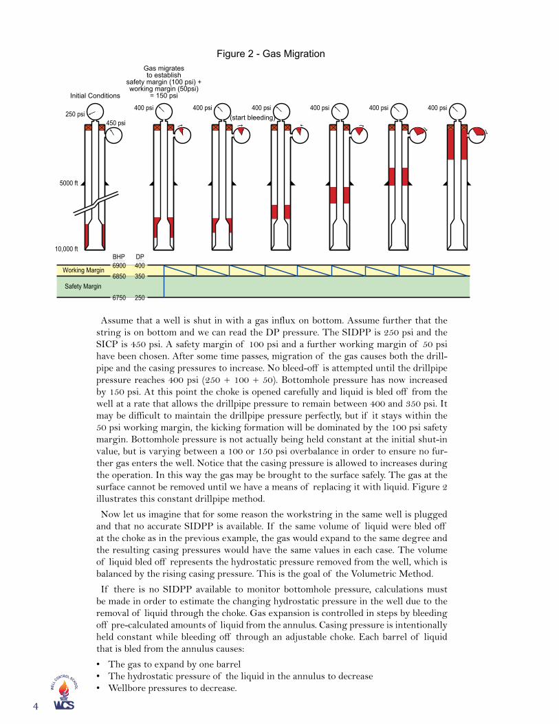
Assume that a well is shut in with a gas influx on bottom. Assume further that the string is on bottom and we can read the DP pressure. The SIDPP is 250 psi and the SICP is 450 psi. A safety margin of 100 psi and a further working margin of 50 psi have been chosen. After some time passes, migration of the gas causes both the drill-pipe and the casing pressures to increase. No bleed-off is attempted until the drillpipe pressure reaches 400 psi (250 + 100 + 50). Bottomhole pressure has now increased by 150 psi. At this point the choke is opened carefully and liquid is bled off from the well at a rate that allows the drillpipe pressure to remain between 400 and 350 psi. It may be difficult to maintain the drillpipe pressure perfectly, but if it stays within the 50 psi working margin, the kicking formation will be dominated by the 100 psi safety margin. Bottomhole pressure is not actually being held constant at the initial shut-in value, but is varying between a 100 or 150 psi overbalance in order to ensure no fur-ther gas enters the well. Notice that the casing pressure is allowed to increases during the operation. In this way the gas may be brought to the surface safely. The gas at the surface cannot be removed until we have a means of replacing it with liquid. Figure 2 illustrates this constant drillpipe method.
Now let us imagine that for some reason the workstring in the same well is plugged and that no accurate SIDPP is available. If the same volume of liquid were bled off at the choke as in the previous example, the gas would expand to the same degree and the resulting casing pressures would have the same values in each case. The volume of liquid bled off represents the hydrostatic pressure removed from the well, which is balanced by the rising casing pressure. This is the goal of the Volumetric Method.
If there is no SIDPP available to monitor bottomhole pressure, calculations must be made in order to estimate the changing hydrostatic pressure in the well due to the removal of liquid through the choke. Gas expansion is controlled in steps by bleeding off pre-calculated amounts of liquid from the annulus. Casing pressure is intentionally held constant while bleeding off through an adjustable choke. Each barrel of liquid that is bled from the annulus causes:
• The gas to expand by one barrel • The hydrostatic pressure of the liquid in the annulus to decrease• Wellbore pressures to decrease.
Figure 2 - Gas Migration
400 psi 400 psi
Gas migratesto establish
safety margin (100 psi) +working margin (50psi)
= 150 psi
(start bleeding)400 psi400 psi400 psi
450 psi
5000 ft
10,000 ft
250 psi
Initial Conditions
400 psi
DP
Working Margin
Safety Margin
400350
250
69006850
6750
BHP

�
The volume of liquid to bleed is the gas expansion required to return bottomhole pressure to formation pressure plus a pre-determined overbalance. Accurate volume measurements are critical. A manual choke is sometimes preferred for greater con-trol when bleeding the liquid. The returning fluid must be measured accurately in a small, calibrated tank. Note that it is important to bleed off liquid from the annulus at a rate that permits the casing pressure to be held constant, but casing pressure is held constant only while bleeding fluid. At other times, the casing pressure is allowed to increase, reflecting the effects of gas expansion. Thus, volumetric control is ac-complished in a series of steps that causes the bottomhole pressure to rise and fall in succession.
To calculate the hydrostatic pressure reduction if one barrel of 12.5 ppg liquid is removed from the well (Figure 1):
Solve for the pressure gradient of the working fluid: 12.5 x 0.052 = 0.65 psi/ft
There are three annular capacities given in the example therefore:
• Casing/DP annulus is 0.05451 bbls/ft therefore: 5000 x 0.05451 = 272.55 bbls• OH/DP annulus is 0.04934 bbls/ft therefore: 4640 x 0.04934 = 228.94 bbls• OH/BHA annulus is 0.02908 bbls/ft therefore: 360 x 0.02908 = 10.47 bbls• 272.55 + 228.94 + 10.47 = 511.96 bbls in the annulus• 511.96 ÷ 10,000 = 0.0512 bbls/ft average annular capacity• 0.65 ÷ 0.0512 = 12.69 psi/bbl average pressure exerted per barrel in the annulus
It is true that the annulus around the BHA represents the highest pressure per barrel (0.65 ÷ 0.02908 = 22.35 psi/bbl) and therefore provides the greatest safety, however the BHA is only 360 ft long, and in this case it is probably safe to use the lower value. However, it must be stressed that this is a well-specific judgment. Other factors, for instance formation strength, must be considered when selecting pressures and bleed-off cycles.
Convert the working margin of 50 psi to bleed-off barrels per cycle:
50 psi ÷ 12.69 psi/bbls = 3.94 bbls therefore let 4 bbls be equivalent to 50 psi
Once safety and working margins are selected and the bleed-off cycle versus pres-sure per volume values are determined, the method is implemented by repeating two distinct steps.
Step 1. The gas is allowed to migrate and wellbore pressures increase.
Step 2. Liquid is bled (holding casing pressure constant with the choke) and the wellbore pressures decrease.
The steps are repeated until gas reaches the surface or other kill operations are initiated. In this way bottomhole pressure is held within a range of values that is high enough to prevent another influx and hopefully low enough to prevent formation breakdown.The examples given are simple and offered only as an explanation of the volumetric
principle. Other factors in the field will influence the selection of safety margins, bleed-off volumes, etc. For example, the rate of the gas migration rate can be estimated by timing the pressure increase on the casing gauge, but there is no assurance that the gas will continue to migrate at a constant rate.Suppose the gauge value increased 100 psi in 40 minutes.
100 psi ÷ 40 min ÷ 0.65 psi/ft x 60 min/hr = 231 ft/hr

�
WEL
L C
ONTROL SCHOOL
If the gas influx is at the bottom of a cased hole, a fairly accurate estimate of the original kick height may be made providing the original pit gain is accurate. Even so, other factors (many unknowable) may be considered when the gas begins to rise in the well. The pressure within the gas is affected by changes in temperature as well as the type(s) of gas encountered and also by the degree of solubility of the gas. Hydrocar-bon gases are highly soluble in oil-based fluids, especially in deep wells. With regard to drilling in open hole, the length of the rising gas (assuming it remains a unified bubble) will change with changes in annular diameters. The bubble would obviously be longer around a large diameter bottomhole assembly and shorter in a washed out section of open hole. These changes in height affect the annular hydrostatic pressure and conse-quently, the casing pressure. This example is illustrated in the three following figures. Figure 3 plots casing pres-
sure against liquid volume bled off. Note that no liquid is bled until the casing pressure has increased from its shut-in value of 450 psi to 600 psi, the combination of our safety and working margins. At that point, 4 bbls of liquid is bled from the well while holding casing pressure constant at 600 psi. When 4 bbls have been removed from the well, the choke is closed and the casing pressure is allowed to increase to 650 psi before the next bleed-off begins. The maximum pressure in the illustration is about 980 psi. At that point in the example the gas is at the surface.
400
600
800
1,000
0 5 10 15 20 25 30 35
Mud Volume Bled Off - Bbls
Cas
ing
Pre
ssur
e -
psi
Figure 3 - Volumetric Well Control
Figure 4 on the following page is a plot of bottomhole pressure against liquid bled off during the operation. Although the BHP is approximately constant throughout, the graph indicates a slight increase over the entire operation. The increase is due in part to our selecting 4 bbls as a practical bleed cycle volume. Calculations indicated that 50 psi is actually equivalent to 3.94 bbls in this well. Also, as the gas migrated up the well and moved into different annular dimensions, the true hydrostatic pressure per barrel changed. However, when planning the operation, we used an average hydrostatic pres-sure per barrel over the entire well.

�
6,700
6,800
6,900
7,000
7,100
0 5 10 15 20 25 30 35
Mud Volume Bled Off - Bbls
Bot
tom
-Hol
e P
ress
ure
- p
si
Figure 4 - Volumetric Well Control
Figure 5, a plot of liquid bled off versus time, illustrates several interesting facts. Assuming that the gas was migrating steadily at a rate of 250 ft/hr, it required more than 2 hours (about 150 minutes) before the casing pressure increased by the safety and working margins, and that 1400 minutes, more that 23 hours, passed before we finished bleeding off our first 4 bbls of liquid (at a constant casing pressure of 600 psi)! At the end of the operation a total of about 31 bbls of liquid were bled from the well.
0
5
10
15
20
25
30
35
Mud
Vol
ume
Ble
d O
ff -
Bbl
s
Figure 5 - Volumetric Well Control
5 hrs 10 hrs 15 hrs 30 hrs 35 hrs 40 hrs20 hrs 25 hrs
Time - Hours

�
WEL
L C
ONTROL SCHOOL
The Lubricate & Bleed MethodThe Lubricate and Bleed Method is an application of the Volumetric Method and is
used to safely remove gas at the surface when it is not possible or practical to circulate the gas out. In the Lubricate and Bleed Method, liquid is pumped into the well and al-lowed to fall down through the gas into the annulus. Sufficient time must be allowed for the liquid to fall through the gas, thus increasing the annular hydrostatic pressure. Once the annular hydrostatic pressure is increased as a result of the pumped liquid, casing pressure may be reduced by that value.
The operation entails pumping a carefully measured volume of liquid into the well. The height of the pumped liquid is determined, and then converted to hydrostatic pressure. This value will subsequently be bled off on surface.
It is important to avoid excessive pressures when pumping liquid into the well. There will be some compression of the gas when injecting the liquid. The pump forces liquid into the well, which increases the pressure imposed throughout the well. Pressure, and therefore injected liquid volume, should be limited according to the specific well char-acteristics. A high pressure/low volume pump is best for this operation.
After injecting the liquid, a judgment must be made as to the time it takes the liquid to fall through the gas. It is important that the liquid falls below the choke to ensure that only gas is bled off. Waiting time will vary depending on well geometry, the type of fluid injected, and the section of the well into which it finally settles. This may take 30 minutes or longer. When bleeding gas, the casing pressure is reduced by the hydro-static gain plus the increase in pressure from gas compression that was noted when the liquid was injected. The operation is completed when the gas has been removed and the well is full of liquid.
EXAMPLEUsing data from previous examples:Surface pressure (SICP): 1000 psi Open hole: 8.5 inDrillpipe: 4.5 in, 16.6 lbs/ftBHA: 6.5 in, 360 ftMud weight: 12.5 ppg Pump output: 0.044 bbls/stk
If we choose to increase surface pressure by a given value, say 100 psi, throughout the procedure, less and less pumped liquid will be required to achieve the 100 psi in-crease as the gas volume in the well is reduced. It is impossible to accurately predict the volume/pressure relationship during the entire operation. In the example below 50 psi is chosen because, 1) it is a relatively low-pressure increase and, 2) it is our chosen working margin.

�
Determine the pressure exerted by one barrel in the casing/drillpipe annulus.
0.65 psi/ft ÷ 0.05451 bbls/psi = 11.9 psi/bbls
Determine the volume of liquid equivalent to 50 psi hydrostatic pressure.
50 psi ÷ 0.65 psi/ft = 76.9 ft
76.9 x 0.05451 bbls/ft = 4.19 bbls
Determine the pump strokes required to pump 4.19 bbls.
4.19 bbls ÷ 0.044 bbls/stroke= 95.3 or 95 strokes
The pump is brought online carefully to overcome wellbore pressure and liquid is pumped into the well until the casing pressure increases by 50 psi or until 95 strokes have been pumped, whichever comes first. At this point a judgment must be made as to the time to allow the injected liquid to fall beneath the choke and the full hydrostatic effect has been gained. After the allotted time has passed, the choke is opened and the casing pressure is reduced according to the increase in hydrostatic pressure plus the pressure increase due to compression. As the operation continues, the volume per stage will decrease and the pressure due to compression will increase.
This procedure, injecting fluid, waiting for it to change place with the gas in the well, then bleeding off casing pressure, is repeated until the annulus is full of fluid and cas-ing pressure is reduced as much as feasible.
If the well was under balanced, the space that the gas occupies in the wellbore must be replaced with a fluid heavy enough to compensate for the under balance (this may not be predictable or possible if we really want to kill the well). The graph(s) below illustrate the Lubricate and Bleed operation. Notice that if we continue to use 50 psi as our target pressure increase, the volume of liquid pumped into the well on each step is reduced. That is, as the well is filled with liquid, less pumped volume is required to achieve the 50 psi target. Some well-specific decisions must be made as to how the final bleed-offs will be accomplished. The techniques used to remove the last of the surfaced gas will depend upon the pumps being used and company preference.

�0
WEL
L C
ONTROL SCHOOL
400
500
600
700
800
900
1,000
1,100
0 5 10 15 20 25 30 35 40
Cumulative Volume Mud Pumped - Bbls
Cas
ing
Pre
ssur
e -
psi
Figure 6 - Lubricate and Bleed
6,950
7,000
7,050
7,100
7,150
0 5 10 15 20 25 30 35 40
Cumulative Volume Mud Pumped - Bbls
Bot
tom
-Hol
e P
ress
ure
- p
si
Figure 7 - Lubricate and Bleed

��
Summarizing this section: The Volumetric Method is used to:• Control bottomhole pressure while allowing migrating gas to expand as it rises in
a well,• Replace the gas at the surface with mud, while maintaining control of bottomhole
pressure (Lubricate and Bleed).
0
5
10
15
20
25
30
35
40
Vol
ume
Mud
Pum
ped
- B
bls
Figure 8 - Lubricate and Bleed
2 hrs 4 hrs 10 hrs 12 hrs6 hrs 8 hrs 14 hrs 16 hrs 18 hrs 20 hrsTime - Hours

��
WEL
L C
ONTROL SCHOOL
Stripping in: The process of lowering the drill stem into the wellbore when the well is shut in on a kick and when the weight of the drill stem is sufficient to overcome the force of well pressure. Stripping out is the process of removing the drill stem from a well under pressure.A Dictionary for the Petroleum Industry (2nd edition, Petex)
The expression used to describe the situation that requires stripping is “pipe heavy”.
If the forces from the well are greater than the weight of the pipe the situation is con-sidered “pipe light”. In pipe light conditions the operation of moving pipe in a well is known as snubbing. Snubbing is a highly specialized operation requiring special equip-ment, i.e., hydraulic workover units or coiled tubing units, and will not be addressed in this discussion.
Some of the most serious well control events have occurred when tripping pipe out of a well. When tripping out, bottomhole pressure (BHP) is reduced in three distinct ways: 1) Annular friction loss disappears when the pump(s) are stopped, 2) there is some decrease in BHP due to the upward movement of the pipe, and 3) the level of liquid in the well goes down as pipe is removed. Improper fill-up on trips out of a well, especially when the bottomhole assembly (BHA) is being pulled through the ro-tary table, has led to many blowouts. Also, the reduction of BHP due to the upward movement of the pipe, that is, the “swabbing effect”, if handled improperly, can lead to disastrous consequences. The main contributors to swabbing are:
• The rate at which the pipe is pulled
• The flow properties of the working liquid (viscosity and gel strength)
• Annular clearances
Swabbing is a piston-like effect caused by pulling the pipe faster than the liquid can fall below it. The opposite effect, surging, which causes an increase in BHP, can also lead to well control problems, but not as often as swabbing.
Swabbing or surging can only be detected early by carefully monitoring a calibrated trip tank as the pipe is moved into or out of a well. On trips out, if the well does not take the pre-determined correct volume of liquid for fill-up, it can be assumed that swabbing of formation fluids into the wellbore has occurred.
It has long been known that the only way to get complete control of a well is to have a workstring near bottom and to have the means to circulate. That statement in itself is essentially true. However, the means by which the pipe is run to bottom is critical. Running back to bottom in an open well, that is, “outrunning the kick” has led to many disastrous blowouts. If it is okay to run in so long as the well is not flowing “too bad”, then “too bad” begs a definition. How bad is too bad? The following figures illustrate how a common, swabbing incident can turn into a dangerous well control incident.
Stripping Operationss
ec
tio
n
�

��
When drilling an 8-1/2 inch hole, the bit penetrated a different formation and a trip had to be made for bit change. The TVD was 9,186 ft. The mud weight was 14.9 ppg which pro-vided approximately 494 psi overbalance, or trip margin. The formation pressure gradient was es-timated to be 0.721 psi/ft. The formation contained gas with an estimated density of 2.5 ppg.
After pulling out of the hole to 5,577 ft, it was no-ticed that the well was not taking the correct volume for fill-up and the well was flowing slowly. The pits had gained about 9.4 bbls due to incorrect fill-up and possible gas expansion. The open hole was now filled with gas cut drilling fluid. The on-bottom over-balance was reduced to 290 psi.
Stage �
Stage �
Outrunning a Kick?D
epth
(ft)
3,500
4,500
5,500
6,500
7,500
8,500
9,500
10,500
11,500
5,577 ft
Pressure
9,186 ft
290 psi
3,500
4,500
5,500
6,500
7,500
8,500
9,500
10,500
11,500
9,186 ft
Dep
th (
ft)
Pressure
494 psi
Mud Hydrostatic
Pore Pressure
��
WEL
L C
ONTROL SCHOOL
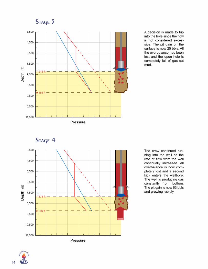
A decision is made to trip into the hole since the flow is not considered exces-sive. The pit gain on the surface is now 25 bbls. All the overbalance has been lost and the open hole is completely full of gas cut mud.
The crew continued run-ning into the well as the rate of flow from the well continually increased. All overbalance is now com-pletely lost and a second kick enters the wellbore. The well is producing gas constantly from bottom. The pit gain is now 63 bbls and growing rapidly.
Stage �
Stage �
3,500
4,500
5,500
6,500
7,500
8,500
9,500
10,500
11,500
7,218 ft
Dep
th (
ft)
Pressure
9,186 ft
3,500
4,500
5,500
6,500
7,500
8,500
9,500
10,500
11,500
7,874 ft
Dep
th (
ft)
Pressure
9,186 ft

��
The well is closed in with the BOPs. Total volume gained is now 94 bbls. The shut in casing pres-sure (SICP) is 725 psi with the bit still 1,312 ft from bottom. The open hole is loaded with gas and con-trol has effectively been lost. Recovery from this situation is now difficult and very risky.
Stage �
Consider a trip out of a well with a drilling rig. If, during the trip, the volume of liq-uid pumped into the well is less than the pre-determined correct volume displacement of the pipe (considering the particular well’s normal characteristics) the trip should be stopped, a full opening safety valve made up on the workstring, and the well checked for flow. If the well is flowing it must be shut-in so that the flow is stopped as quickly as possible and so that the situation can be analyzed under static conditions. Even though the well is not flowing, once it has been determined that formation fluid has been swabbed into a well the pipe should be stripped back near bottom and the influx circulated out using a constant bottomhole pressure method.
Safe stripping practices involve two primary concerns. There is the mechanical opera-tion itself that consists of the rig-up and operation of equipment, specific assignments for the crew, and careful displacement and volume calculations. Also, since some gas is associated with most formation fluids, consideration must be given to controlling bottomhole pressure in the event of gas migration during the stripping operation. Al-though both of these concerns are addressed simultaneously during actual operations, here they are discussed separately for the sake of simplicity and clarity.
The basic equipment requirements for stripping pipe into a well using an annular preventer against relatively low pressure are:
• A fluid-discharge system from the wellhead (BOP) into a dedicated and accurately calibrated tank, in order to allow controlled bleed-off.
• A BOP control system that allows fast response and guarantees a seal when a tool joint is stripped through the sealing element.
• Additional equipment to ensure efficient operations.
3,500
4,500
5,500
6,500
7,500
8,500
9,500
10,500
11,500
7,874 ft
Dep
th (
ft)
Pressure
9,186 ft

��
WEL
L C
ONTROL SCHOOL
It goes without saying that it is vitally important that supervisors know the limits of their well control equipment and that maintenance and operational manuals are readily available. Unnecessary damage to the sealing elements of preventer(s) during stripping has been the cause of more than one blowout. A brief description of the equipment requirements and operating limitations are discussed below.
Figure 6 below is a schematic layout of the fluid discharge from the wellhead, via the choke line and choke-manifold into a calibrated trip tank. A calibrated strip tank is used to monitor and record volumes of the closed-end displacement of the pipe to be stripped into the well. The trip tank contains the volume increase of gas expansion (as a result of choke manipulation applying the Volumetric Method) and is monitored and recorded separately from the pipe displacement volume.
AdjustableChoke
Flow LineAccuratePressureGauges
(various ranges)
AnnularPreventer
(see detail)
CalibratedTrip Tank
CalibratedStripping Tank
Figure 6 - Rig Layout for Combined Stripping and Static Volumetric Method

��
In many operations, some leakage will occur as a tool joint passes through the an-nular preventer. This liquid must be measured and added to the volume bled from the annulus. Figure 7 above illustrates a line directing any preventer leakage back into the calibrated trip tank.
Figure 8 is a schematic layout of a pressure regulating system used to ensure a fast, guaranteed seal when a tool joint is stripped through the annular preventer. In order to minimize wear on the sealing element, the closing pressure should be reduced as much as possible and the element allowed to expand, and then contract, as the tool joint passes through. Lubricating the drillpipe before and during the operation can further reduce potential wear. If there is leakage around the pipe, the fluid should be collected in the trip tank and considered as liquid from the well. A 10 gallon surge accumulator bottle is installed in the closing line as close as possible to the preventer. The pre-charge pressure of the surge accumulator depends on the type of preventer in use. As rule of thumb, it should be pre-charged to 50% of the minimum required closing pres-sure, for the preventer. The surge bottle is isolated under normal operating conditions, and is used to ease the expansion and contraction of the sealing element.
Figure 8 - Equipment requirements for stripping with an annular preventer
AnnulusBleed Line
Hand AdjustableChoke
Calibrated Measuring Tank(Trip Tank)
Fluid Leaking PastPreventers
Figure 7 - Trip Tank
Nitrogen-charged bag-type accumulator(3,000 psi WP 10 gals capacity)
pre-charged to 400 psi
Make this piping as shortand direct as possible
Closing line to TR typeregulating valve
Remove plug to ventopening chamberduring stripping
Pre-charge fitting
Ball valve
Opening line
3000 psi gauge

��
WEL
L C
ONTROL SCHOOL
Figure 9 illustrates a fail-safe type of regulating valve used when operating the BOPs remotely. The fail-safe valve will maintain the closing pressure in the event that air or hydraulic signals to operate the valve is lost. The TRTM pressure regulation valve illustrated here incorporates a fail-safe feature. With the TRTM regulator, if the pilot pressure is lost, the manual adjusting screw remains in position, thereby maintaining the last regulated pressure setting. An important feature is that the mechanical lock screw remains locked to ensure that the last setting remains.
Surge-Bottle(Pre-charged to
50% of the minimumrequired closing pressure)
Closing Line
OpeningLine
Figure 10 - Blowout Preventer
Another advantage of the TRTM fail-safe regulator valve is high flow-through vs. valve size due to mul-tiple internal flow paths; therefore, it is responsive to stripping operations due to the multi-port vent line.
Regulating Air PressureNormal Vented FluidRegulated Control Pressure3000 psi Hydraulic SupplyWell Pressure
Figure 9 - Fail-Safe Regulator Valve
3000
0
600
0
BOP Stack
“Open”Line
“Closed”Line
AnnularControlValve
Accumulator
Pump

��
The Hydril GK preventer, illustrated in Figure 10 on the previous page, was de-veloped especially for use on surface installations. Pack-off is effected by hydraulic pressure applied to the closing chamber that raises the piston, forcing the packing element into a seal around the tubular pipe (the GK will also seal on the open hole, but this is normally avoided because of the potential for extreme packer wear).The GK is designed to be pressure assisted so that pressure from the well is acting up
on the packing element. As well pressure increases, closing force increases and there-fore the friction forces developed by the moving pipe also increase. Longer packing unit life is obtained by lowering the closing chamber pressure. Manufacturer’s tables are available for various make and model preventers and should be used as guides for establishing the initial closing pressure.The chart below illustrates the differences in recommended minimum closing pres-
sures of various types of annular preventers.
Stripping ExamplesIn this first example assume the same well geometry taken from the previous volu-
metric discussion, and that a 15 bbls gas influx was swabbed into the well and de-tected 25 stands (2,325 ft) off bottom. The decision is made to strip back into the well and circulate the kick out. Also assume that the 12.5 ppg mud balanced the formation before the trip was started and that the gas will not migrate. The 115 psi casing pres-sure is relatively low surface pressure so the annular preventer will be used as the stripping head. As in the volumetric discussion, a safety margin of 100 psi and a work-ing margin of 50 psi are chosen. These assumptions may not reflect a true situation; they are used here for illustration purposes only.
2K 3K 4K 5K1K
1500
1000
500
0
Well Pressure (psi)
Clo
sing
Pre
ssur
e (p
si)
For 5” dp Only
GK 13 5/8” 5000 psi
All type D 5000 psi
13 5/8” 5000 psi
Shaffer Spherical
Figure 11 - Closing Pressures

�0
WEL
L C
ONTROL SCHOOL
WELL DATA
Depth: 10,000 ft
Casing: 9-5/8 in, 40 lbs/ft, set at 5,000 ft
Drill Pipe: 4-1/2 in, 16.6 lbs/ft, closed end displacement 0.02084 bbls/ft
Off bottom, an influx is swabbed in below the workstring.
Fluid density: 12.5 ppg
SICP: 120 psi
Final pit gain after shut in: 15 bbls
Formation pressure: 6,500 psi
The closed-in displacement of the 4-1/2 in drillpipe with tool joints is 0.02084 bbls/ft therefore each 93 ft stand displaces 1.94 bbls (0.02084 x 93 = 1.94). After the proper equipment is rigged up, a detailed safety meeting is held. During this meeting the crew is informed as to the details of the operation and individual tasks are assigned and explained.
The operation begins by stripping the drillpipe through the annular preventer with the choke closed until the casing pressure has increased by the safety margin (100 psi) and the working margin (50 psi), that is, to 270 psi. From this point onward the choke is opened as the pipe is moved into the well in order to bleed off exactly the drillpipe displacement. The trip tank should be approximately 1/3 full before stripping begins. In this ideal situation (no migration) the casing pressure would remain approximately constant as the pipe is stripped until the BHA stings into the top of the influx. At that point the annular hydrostatic pressure would be reduced as a result of the lon-ger (higher) influx. The casing pressure would then increase reflecting the changing wellbore geometry. It can be seen that accurate measurement of the displaced liquid is crucial to the operation and that communication between the choke operator and the men measuring the liquid must be excellent. Bottomhole pressure remains constant so long as the returning liquid equals the actual pipe displacement until the workstring is at, or near, the bottom of the well. Any changes in casing pressure are due to changes in annular hydrostatic pressure as pipe is moved into the well.
Figure 12 - Pipe Displacement

��
The example on the previous page assumed that no gas was associated with the swabbed-in influx and therefore there was no upward migration. However, almost all kicks contain some gas and stripping operations must be prepared to control bottom-hole pressure if the gas begins to rise in the well. Since circulation is not possible, the volumetric principle is incorporated into the stripping operation. In this situation there are two separate concerns, 1) careful measurement of pipe displacement and, 2) the application of the Volumetric Method in order to allow for gas expansion and control of bottomhole pressure.
When planning a stripping operation, it is not practical to consider every geometric change in the wellbore even though the migrating gas may move into different annuli, for example, above the BHA. Also, as mentioned in the previous example, consideration must be given to the potential pressure change that will likely occur when the BHA stings into the main body of the gas. If the vertical length of the gas increases, it will result in a decrease in the effective annular hydrostatic pressure, which in turn, results in an increase in casing pressure. It is important to realize that this increase in surface pressure is not due to gas migration.
Although it is possible to estimate the rate of migration, there is no assurance that this rate will continue. Also, the exact top (or bottom) of the bubble cannot be known. Since a well may have various annuli, the hydrostatic pressure per barrel of liquid will vary depending on the position of the bubble. When selecting a hydrostatic pressure value versus volume to be used (psi/bbl), some operators simplify matters by using the annulus between the BHA and open hole, considering the smallest annulus to be the safest. Others use an average, or the longest annulus. In most wells the pressure per barrel differences between the various annuli are small. At any rate, the choke operator should anticipate a significant pressure change when the BHA enters the gas bubble.
Choosing appropriate safety and working margins also varies according to specific well characteristics. For example, formation strength (MASP) is always a concern in drilling because there is exposed open hole. There is no hard rule but if the MASP were 1200 psi, and the SICP were 800 psi, the selection of 200 psi total margins would likely be safe since 1200 – 800 = 400 psi, which should provide ample tolerance. If cas-ing pressure does not increase after a few stands are tripped in, it could mean that the well is already taking liquid and that the fracture pressure has been exceeded. Once it is established that the well is taking working fluid, stripping may continue by bleeding just enough fluid to equal the total displacement of the pipe. In this situation, less fluid would be forced into the formation and the losses might stop once the gas rises above the fracture point.
Some basic assumptions are made in the following example.
• The annular preventer is used for stripping.
• The influx will be considered to be gas and therefore backpressure will be added, allowing for migration and expansion as in the Volumetric Method.
• The influx remains in a continuous bubble, occupying the entire annulus cross-sec-tion.
• Safety and working margins will be added at the very start of the operation and the influx will be in the open hole at the beginning of the operation.
An average psi/bbl will be used for volumetric guidelines. Here we determined the average by dividing the formation pressure of 6500 psi by the total annular volume when the workstring is on bottom (512 bbls).
��
WEL
L C
ONTROL SCHOOL
Like safety margins, this must be a well-specific judgment. Some of the additional considerations required are: estimates of the bubble position, maximum allowable pressures, and length of open hole in relation to the casing seat.
Suppose the crew has received orders to strip back to bottom before circulating the gas influx out. During the stripping operations pipe will be moving, gas may be mi-grating, and fluid will be bled off at the choke. A planned stripping pressure schedule should be developed.
The well is shut in with 120 psi casing pressure. In designing a bleed off schedule, a safety margin and a working margin are chosen. In this example we have decided to use 200 psi safety margin (because of the hydrostatic loss of 100 to 150 psi associated with the bit passing through the kick) and a 50 psi working margin. In other words, the choke will not be opened for any bleed off until the casing pressure has been allowed to rise to 370 psi. During first bleed off, casing pressure will be maintained within our working margin, that is, between 320 and 370 psi.
It is necessary to carefully measure any fluid bled from the well and to estimate its equivalent hydrostatic pressure. Tubing will be fitted with at least one backpressure valve so total displacement will be that of the full outside diameter.
0.02084 bbls/ft x 93 ft = 1.9 bbls/stand, closed-in pipe displacement
6500 psi ÷ 512 bbls = 12.7 psi/bbls, pressure equivalent chosen for volumetric adjust-ments
50 psi ÷ 12.7 psi/bbls = 3.9 bbls, working margin equivalent in barrels
With this information, a stripping/bleed off schedule is created. Using the schedule, the following steps describe the procedure when the drillpipe is continuously stripped into the well.
1. Strip into the well without bleeding fluid until casing pressure increases by 250 psi (200 psi for safety margin and 50 psi for working margin) from 120 psi to 370 psi.
2. Once the casing pressure has reached 370 psi, continue bleeding at a rate to hold casing pressure between 320 and 370 psi. After bleeding the equivalent of 50 psi (working margin) of liquid, that is, 4 bbls, allow the casing pressure to increase by another 50 psi to 420 psi.
3. As pipe is lowered, carefully bleed off the amount of tubing displacement (1.9 bbls per 93 ft stand) as it is run into the well. The casing pressure is allowed to increase. If the casing pressure has not increased by 50 psi after the stand is lowered and set on the slips, close the choke, and make up the next stand. Continue bleeding only pipe displacement when the connected stand is lowered.
4. When casing pressure has increased to 420 psi while continuing to strip, maintain casing pressure between 370 and 420 psi while bleeding until a gain of 4 bbls is noted. At this point, casing pressure is once again allowed to increase as the bubble migrates and pipe is run into the well.
The steps are repeated until drillpipe has been run to bottom or gas reaches surface.
It is important to note that these are not recommendations, but are offered to demon-strate the complexity of the operation, and the critical need for thorough preparation before beginning to strip into a well.

��
The following three graphs (Figures 13, 14 and 15) illustrate a computer simulation using the data in our example. Figure 13 illustrates the movement of the BHA into the well as the kick migrates upward. Some assumptions were made in order to develop the plots. (1) The bubble is migrating at a rate of 250 ft/hr. (2) Pipe is being stripped at a rate of 1000 ft/hr. (3) Each connection takes 2 minutes and a stand is moved into the well in 3.8 minutes, making the total stripping time 5.8 minutes per stand.
Figure 13 - Stripping in the Hole7,000
7,500
8,000
8,500
9,000
9,500
10,000
Dep
th -
Fee
t
1 hr 2 hrs 3 hrs 4 hrsTime - Hours
Kick Top
Bit Depth
Top BHA
Kick Bottom
Figure 14 - Bit Penetrates the Kick
0
100
200
300
400
500
600
Pre
ssur
e (p
si)
or H
eigh
t (ft
)
1 hr 2 hrs 3 hrs 4 hrs
Time - Hours
Kick Height
Casing Pressure
For illustrative purposes: Bleeding for pipe displacement + capacity only NO Bleeding for kick migration!
BHA entering gas
BHA begins to exit bottom of gas
Gas completely above BHA

��
WEL
L C
ONTROL SCHOOL
Notice in Figure 14, which illustrates pipe displacement only, that approximately 3 hours into the operation both the casing pressure and the kick height increase for about 30 minutes and then begin to decrease. As the BHA enters the gas, the length (height) of the kick increases, effectively reducing the annular hydrostatic pressure. The de-crease in hydrostatic pressure is offset by the resulting increase in casing pressure. As the BHA exits the bottom of the gas, the kick becomes shorter, mud hydrostatic pres-sure increases, and the casing pressure decreases. Once the gas is completely above the BHA, the gas occupies the larger annulus around the drillpipe only. At that point the kick height remains constant (because for clarity we have assumed no bleeding for kick migration), hydrostatic pressure is constant, and casing pressure increases as the kick brings its pressure up the hole. It is important to note that this necessary increase/de-crease in casing pressure that occurs when the BHA passes through the bubble is one reason why we strip pipe based on volume calculations, not on forced changes in casing pressure.
The Figure 14 plot was developed using 1.94 bbls/stand as calculated. It is interest-ing to note that if the closed-in displacement were rounded up to 2 bbls/stand - a seemingly small adjustment - the well would be under-balanced by 150 psi by the time the bit was at bottom!
The bottomhole pressure/time plot in Figure 15 assumes three different gas migra-tion and stripping rates. The graph was generated using the following assumptions:
• Safety margin – 200 psi• Working margin – 50 psi• Bleed-off for stripping – 1.9 bbls/stand• Bleed-off for migration – 3.9 bbls for the 50 psi working margin• Assumed connection times were 2, 5, and 8 minutes for stripping rates of 1000, 500,
and 250 ft/hr respectively.
Figure 15 - Volumetric Stripping
6,500
6,550
6,600
6,650
6,700
6,750
6,800
Bot
tom
-Hol
e P
ress
ure
- p
si
Bit on Bottom
Migration Rate / Stripping Rate (ft/hr)
250 / 1,000 500 / 5001,000 / 250
1 hr 2 hrs 5 hrs 6 hrs3 hrs 4 hrs 7 hrs 8 hrs 9 hrs 10 hrsTime - Hours

��
The safety and working margins were established by migration only. No stripping began until the bottomhole pressure had increased to 6750 psi. Note that at the slowest assumed migration rate (depicted in red) about 2 hours were required to achieve the 250 psi over balance. Continuing to follow the 250 ft/min rate, it can be seen that the BHA had been stung through the gas in about 4 hours and that in less than 5 hours the bit was on bottom even though our working margin of 50 psi (3.9 bbls) had not yet been bled from the well.
Doubling the migration rate to 500 ft/hr and slowing the stripping time by half i.e., 500 ft/hr required approximately 5 hours to reach bottom but still, the working mar-gin equivalent had not been completely bled from the well.
In the third case (blue) the migration rate has increased 4 times while the stripping speed has been reduced to only 250 ft/hr. In this case it was about 9 hours into the operation before the 3.9 bbls were bled. Less than an hour later the bit was at bottom. The increase in BHP after the 3.9 bbls (for migration) is achieved is due to stripping and bleeding pipe displacement only, re-establishing the working margin.
It can be seen from these illustrations that volumetric stripping can be a complicated operation, and that it is impossible to predict exactly what will happen once the opera-tion begins. Although the plotted data are generated by computer modeling and not from actual case studies, they demonstrate the complexity of stripping into a well safely while maintaining bottomhole pressure within a designed range or “window” for optimum safety, protecting not only the crew and equipment, but also the environ-ment.
The following steps represent a summary of recommended low pressure stripping procedures developed by a major operator. They are offered here as information only since specific procedures differ among operators.
1. After the well is shut in, casing pressure is monitored carefully. Pressure is recorded every 5 minutes in order to determine if the influx is migrating.
2. Rig up equipment for stripping and prepare a stripping schedule, determining safety and working margins, closed-pipe displacement, psi/bbl calculations, etc.
3. Reduce the closing pressure on the annular preventer and open the surge accumula-tor bottle.
4. Conduct a safety meeting for all personnel, explaining the operations, assigning tasks, and establishing paths of communication for the operation.
5. Install an Inside BOP (IBOP) on top of the full opening safety valve (FOSV)
6. Open the FOSV slowly checking that the IBOP is holding. If a non-ported check valve (float) is in the BHA it is unlikely that there will be pressure below the FOSV.
7. Consider circulating for a short time to confirm that the workstring is not plugged before beginning to strip.
8. Ensure that the choke line and manifold are properly aligned to discharge bled off liquid into the trip tank and that the trip tank is approximately 1/3 full.
9. Install a stand of drillpipe, making sure that pipe rubbers are removed; tong and slip marks are smoothed as much as possible, and the tool joints are lubricated.
10. Allow the casing pressure to increase until it equals SICP + safety margin + work-ing margin while stripping the first stand.
11. Fill each stand stripped with fluid from the active system.
12. Move the tool joints slowly through the preventer, avoiding excessive pressure surges.

��
WEL
L C
ONTROL SCHOOL
13. While stripping, the volume increase due to the closed-end displacement of the pipe and the expansion volume are purged into the trip tank. After stripping the entire stand, bleed the displacement volume into the stripping tank. This ensures that any increase in the trip tank volume is due to gas expansion and the resulting loss of hydrostatic pressure in the well.
14. While stripping the next stand, allow the casing pressure to increase from its present value plus the working margin.
15. Continue stripping, repeating steps 11-15 as often as necessary, allowing migra-tion and volumetric control until the string is near bottom.
16. Prior to circulating, close a ram preventer in order to have full closed-in integrity when the gas is near the surface.
17. Route the returns from the annulus through the mud/gas separator.
18. Once the influx is circulated out and before opening the preventer, be aware that pressure may be trapped in the BOP stack and/or below the IBOP.
High Pressure StrippingThe previous discussions have outlined the basics of stripping into a well against
relatively low wellbore pressure using an annular preventer. In high-pressure situa-tions two preventers are used to strip into or out of a well. When two preventers are used the operation is more critical and much more complex. High pressure stripping is discussed briefly below, but it must be stressed that each well is different and a detailed explanation of high pressure stripping operations is beyond the scope of this text.
Stripping With an Annular and One Ram PreventerIf the force required to pass the combination of FOSV, IBOP and tool joint through
the annular preventer is too great, i.e. there is not enough string weight available, a ram preventer can be used in conjunction with the annular preventer. Providing space-out distances permit, the steps are:
1. Close the appropriate ram.
2. Bleed off pressure trapped between the annular and the ram.
3. Lower the closing pressure of the ram to a pre-determined value.
4. Open the annular preventer.
5. Strip pipe slowly through the ram, until the upset of the tool joint gently tags up on the ram block.
6. Pick up to the original hookload and close the annular preventer.
7. Using a high pressure/low volume pump, apply pressure between the closed pre-venters equal to the casing pressure.
8. Open the ram.
9. Use tags to indicate which preventer is containing the wellbore pressure.
10. Continue repeating the cycle until enough string weight is available to strip with the annular preventer alone.
Stripping in with Pipe RamsHigh pressure stripping operations and properly arranged BOP stacks are required
for ram-to-ram stripping. Often, a trained stripping crew conducts the operation. BOP stack arrangement is crucial. The rams must be spaced far enough apart so that tool joints will not be trapped in either ram when both are closed. This requires a single
��
ram with a spacer in the stack. Adjacent rams in double or triple sets cannot be used for stripping. If the lower rams are reserved as a master valve, or safety ram, ram-to-ram stripping would require a four-ram stack.
Although the packing elements in pipe ram blocks are designed to extrude and hold a seal for a long period of time, pressure on the closing side of the rams is reduced to avoid burning the ram packing as the pipe is sliding through. There are no rules about pressure on the closing side of rams, but 400-500 psi is recommended by some operators. The upper ram set is used for the majority of stripping and the lower set is primarily used to seal the well as tool joints pass through. Bottomhole pressure is controlled by carefully measuring liquid returns and making the necessary volumetric corrections.
Stripping Out of a WellBefore stripping out of a well, consideration must be given to the fact that at some
point there will not be enough pipe weight for the pipe to stay in the well against the wellbore pressure. Calculations are made in order to estimate the balance point. The crew and equipment must be fully prepared to handle the change in well conditions.
Prior to beginning, precautions must be taken to ensure that the workstring is closed. Pump-down type back pressure valves (BPV), properly seated, are often used for this purpose. Safety valves, made up on the string are kept open when pulling the pipe so that if the BPV leaks, it will not pressure up the string.
Liquid is pumped into the annulus to keep the hole full. There are a number of ways to do this. A common technique is to arrange to circulate across the BOP stack from the kill to the choke line. A high pressure/low volume pump, like a cementing pump, generally works better than rig pumps. The pump is kept running throughout the stripping operation.
Backpressure, greater than the casing pressure, is controlled by choke adjustments. The well is kept full of liquid as the pump circulates across the BOP stack. The liquid is pumped from a single accurately calibrated tank. After each stand, the total pipe displacement is compared to liquid actually taken by the well. Casing pressure is held constant and corrections to volume pumped into the well can be made by choke adjust-ments.
The casing pressure will decrease as the large diameter BHA is pulled out of the kick-ing fluid. However, the upward migration of gas and some upward drag may cause an increase in casing pressure. Corrections to the casing pressure are made according to the principles of the Volumetric Method.
It may become necessary to use the pipe rams as rubber protectors are pulled through an open annular preventer. The pressure between the pipe ram and the annular pre-venter is released before opening the annular preventer.
SummaryStripping operations can range from a fairly simple low pressure operation with a salt
water kick, to an extremely dangerous high pressure gas situation. Each case is differ-ent just as each well is different. For example, in most low-pressure operations pipe can be stripped into a well much faster than the gas will migrate. Some operators may choose to circulate out gas once the pipe has been run into, or below the gas. Detailed procedures for various stripping operations are beyond the scope of this text. How-ever, three well-worn universal statements can be made, 1) prevention is always better than a cure, 2) trying to “outrun” a kick to bottom is not a safe practice, and 3) there is no substitute for careful planning before stripping operations begin.

��
WEL
L C
ONTROL SCHOOL
The following three pages are examples of various worksheets that may be used in planning stripping operations.
Well:Date:
Pre-recorded data:Mud gradient psi/ft MAASP psi
Size of Casing Inches Formations strength gradient (Leak-off or Limit test)
psi/ft
Shoe depth MD/TVD ft. Size of OH ftCasing capacity bbls/ft Drilled depth AH/TVD ftSize & Wt dp ins # OH-DC capacity bbls/ftTooljoint OD inches OH-DP capacity bbls/ftDP cap. & CE displacement bbls/ft Slow circulation rate data:
Pump output bbls/strAvg. CE
displacement/stand bbls20 spm psi 30 spm psiSize/Length of DC’s ins ft40 spm psi
DC cap. & CE displacement bbls 50 spm psi
Float valve in BHA installed
Trip tank capacity bbls/ft Trip tank level increase of 1 stand DP inches
Strip tank capacity bbls/ft Strip tank level increase of 1 stand DP inches
Required friction, loss of hookload, (experienced from previous Strip-drill at zerowellhead pressure) to strip tool joint (FOSV/IBOP) through annular preventer (FBOP). lbs
Pre-chosen Pw (working margin, usually 50 psi) and lbsEquivalent Volume ( (Pw / gradient mud) x OH-DC capacity) bblsKick / Swab data:Bit depth when closed in? ft Closed in when: Swabbed influx volume? bblsStabilized Pdp (SIDPP)? psi Stabilized Pann1 (SICP)? psi Pann1 increasing? (Pann2-Pann1) psi/5min Stripping Calculations:
Ps
Ps=Influx volume x F-factorF-factor = (1 / OHcapacity) x ( mud- gas)x(OH capacity
/ OH-DC capacity -1)psi
Pchoke1 Pchoke1=Pann1+Ps+Pw psi Pchoke2 , etc. Pchoke2=Pchoke1+Pw, etc. psi
Friction weight due to wellhead pressure Fup= /4x(ODTooljointx2.54)2xPann1x0.0102 lbs
Minimum string weight, hookload (HL), required to Strip through annular preventer with tool joint.
Minimum required HL= Fup+ Fannular BOP lbs
Circulation Calculations:Drillpipe volume bbls Drillpipe/Casing volume bblsBHA volume bbls Drillpipe/OH volume bbls
BHA/OH volume bbls
Total drillstring volume: bbls Total annular volume: bbls
Volumetric Stripping Worksheet

��
Well:Date:
Triptank level at:Starting level (level1) inches Pchoke4 (level5=level4+ V) inchesPchoke1 (level2=level1+ V) inches Pchoke5 (level6=level5+ V) inchesPchoke2 (level3=level2+ V) inches Pchoke6 (level7=level6+ V) inchesPchoke3 (level4=level3+ V) inches Pchoke7 (level8=level7+ V) inches
Actual Data: *Triptank level recorded, is actual level after a draining the closed-in volume of 1 stand into the Strip-tank.
Time: Stand #: Pchoke actual: *Trip tank level: Remarks:
Recording Worksheet

�0
WEL
L C
ONTROL SCHOOL
SIWHP psi Fluid Gradient psi/ft
SICTP psi Annular Capacity bbls/ft
Working Margin psi Hydrostatic Pressure Lost psi/bbls
Safety Margin psi Volume per Cycle bbls
Volumetric Method Worksheet

��
Notes

��
WEL
L C
ONTROL SCHOOL
Notes

w w w . w e l l c o n t r o l . c o m

WEL
L C
ONTROL SCHOOL
w w w . w e l l c o n t r o l . c o m