Volume 5 Ancillary Investigatory Works - Reading Brett Associates Field Road Chalk Mines...
41
Peter Brett Associates Consulting Engineers 16 Westcote Road Reading, Berkshire, RG30 2DE T: 0118 950 8777 F: 0118 950 8198 E: [email protected] Client: Reading Borough Council Civic Centre Reading RG1 7TD Funding Agency: English Partnerships Prepared by: D Emanuel Checked by: Eur Ing J C S Talbot Reviewed by: Dr C N Edmonds On behalf of Peter Brett Associates Consulting Engineers Peter Brett Associates disclaims any responsibility to the Client and others in respect of any matters outside the scope of this report. This report has been prepared with reasonable skill, care and diligence within the terms of the Contract with the Client and generally in accordance with ACE Conditions of Engagement (Agreement D) and taking account of the manpower, resources, investigations and testing devoted to it by agreement with the Client. This report is confidential to the Client and Peter Brett Associates accepts no responsibility of whatsoever nature to third parties to whom this report, or any part thereof is made known. Any such party relies upon the report at their own risk. © Peter Brett Associates 2002 Field Road Chalk Mines Stabilisation Project - Phase 1 Volume 5 Ancillary Investigatory Works Project Ref :10 846/100 November 2002
Transcript of Volume 5 Ancillary Investigatory Works - Reading Brett Associates Field Road Chalk Mines...

Peter Brett Associates Consulting Engineers 16 Westcote Road Reading, Berkshire, RG30 2DE T: 0118 950 8777 F: 0118 950 8198 E: [email protected]
Client: Reading Borough Council Civic Centre
Reading RG1 7TD
Funding Agency: English Partnerships
Prepared by:
D Emanuel Checked by:
Eur Ing J C S Talbot Reviewed by:
Dr C N Edmonds On behalf of Peter Brett Associates Consulting Engineers
Peter Brett Associates disclaims any responsibility to the Client and others in respect of any matters outside the scope of this report. This report has been prepared with reasonable skill, care and diligence within the terms of the Contract with the Client and generally in accordance with ACE Conditions of Engagement (Agreement D) and taking account of the manpower, resources, investigations and testing devoted to it by agreement with the Client. This report is confidential to the Client and Peter Brett Associates accepts no responsibility of whatsoever nature to third parties to whom this report, or any part thereof is made known. Any such party relies upon the report at their own risk. © Peter Brett Associates 2002
Field Road Chalk Mines Stabilisation Project - Phase 1
Volume 5 Ancillary Investigatory
Works
Project Ref :10 846/100
November 2002

Peter Brett Associates Field Road Chalk MinesStabilisation Project - Phase 1
Volume 5Ancillary Investigatory Works
Brief Overview of the Project
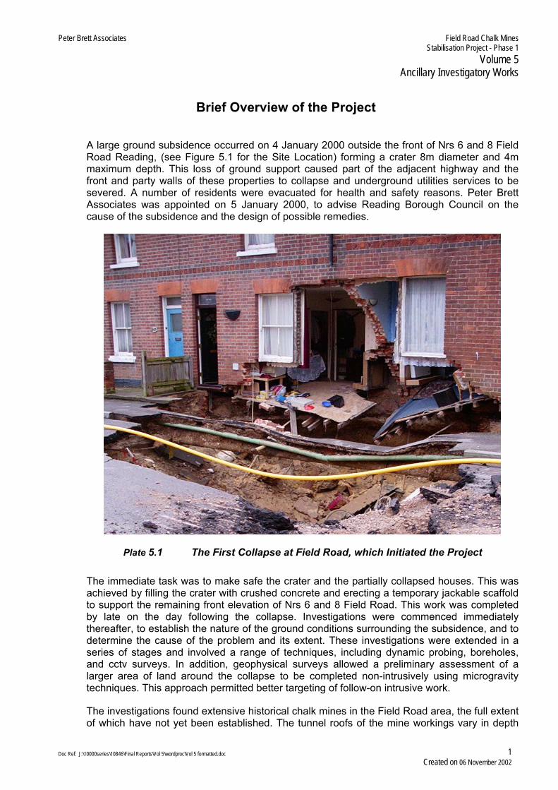
A large ground subsidence occurred on 4 January 2000 outside the front of Nrs 6 and 8 Field Road Reading, (see Figure 5.1 for the Site Location) forming a crater 8m diameter and 4m maximum depth. This loss of ground support caused part of the adjacent highway and the front and party walls of these properties to collapse and underground utilities services to be severed. A number of residents were evacuated for health and safety reasons. Peter Brett Associates was appointed on 5 January 2000, to advise Reading Borough Council on the cause of the subsidence and the design of possible remedies.
Plate 5.1 The First Collapse at Field Road, which Initiated the Project
The immediate task was to make safe the crater and the partially collapsed houses. This was achieved by filling the crater with crushed concrete and erecting a temporary jackable scaffold to support the remaining front elevation of Nrs 6 and 8 Field Road. This work was completed by late on the day following the collapse. Investigations were commenced immediately thereafter, to establish the nature of the ground conditions surrounding the subsidence, and to determine the cause of the problem and its extent. These investigations were extended in a series of stages and involved a range of techniques, including dynamic probing, boreholes, and cctv surveys. In addition, geophysical surveys allowed a preliminary assessment of a larger area of land around the collapse to be completed non-intrusively using microgravity techniques. This approach permitted better targeting of follow-on intrusive work.
The investigations found extensive historical chalk mines in the Field Road area, the full extent of which have not yet been established. The tunnel roofs of the mine workings vary in depth
Doc Ref: J:\10000series\10846\Final Reports\Vol 5\wordproc\Vol 5 formatted.doc 1 Created on 06 November 2002

Peter Brett Associates Field Road Chalk MinesStabilisation Project - Phase 1
Volume 5Ancillary Investigatory Works
from about 7.5m to 11m below ground level. The tunnel floors are typically around 13m to 14m below ground level, while their width is predominantly 3m to 4m. The condition of the mine workings was found to be poor, with many areas of the roof having collapsed. The latter process appeared to be continuing, at a gradually increasing pace. Indeed, during the course of the Project, before the ground had been stabilised, a further four subsidence events occurred near the initial event, three of which caused structural damage to the rear of Nrs 8, 10 and 18 Field Road.
Reading Borough Council successfully applied for and received funding under the Government’s Land Stabilisation Programme, which is administered by English Partnerships as an agency, at the time of application, of DETR (the Department of Environment, Transport and the Regions). This Central Government body subsequently became, for a short time DTLR (Department of, Transport and the Local Regions) prior to coming under the aegis of the Office of the Deputy Prime Minister (ODPM).
After a review of options for treatment, it was concluded that grouting techniques represented the most suitable and economical method for stabilising the chalk mine subsidence problems. Grouting is a process whereby a cement-based liquid is injected into the ground under pressure through hollow metal tubing that has been drilled into the ground. The grout spreads through the ground infilling voids and strengthening weak ground. After completion of the process the grout sets hard within 24 hours, gaining further strength with time.
The grouting works commenced at the junction of Castle Hill with Field Road and proceeded southwards to the south end of the evacuated area, which had been fenced off. The mine workings under the houses were partially stabilised from the road and from their rear gardens, with additional grouting being carried out inside the even-numbered houses, using a portable drill rig.
Plate 5.2 Stabilisation Works Between Nrs 59 and 61 Field Road
Garden restoration works and repairs to the damaged houses started as soon as safe access was available. Work on the gardens and buildings continued after the completion of the
Doc Ref: J:\10000series\10846\Final Reports\Vol 5\wordproc\Vol 5 formatted.doc 2 Created on 06 November 2002

Peter Brett Associates Field Road Chalk MinesStabilisation Project - Phase 1
Volume 5Ancillary Investigatory Works
grouting contract, and repairs were made by the various utilities to their buried services that had been damaged by the mine roof collapses. After repairs and renewals had been made to the buried services, and near the completion of the restoration works to the gardens and buildings, repair of the highway took place.
Following intensive teamwork by all parties involved in the Project, the evacuated residents were able to return to their homes, precisely on programme and before Christmas 2001, exactly 23 months after their initial evacuation.
Doc Ref: J:\10000series\10846\Final Reports\Vol 5\wordproc\Vol 5 formatted.doc 3 Created on 06 November 2002
Peter Brett Associates Field Road Chalk MinesStabilisation Project - Phase 1
Volume 5Ancillary Investigatory Works
Table of Contents for Volume 5 – Ancillary Investigatory Works Brief Overview of the Project..................................................................................................... 1 Table of Contents for Volume 5................................................................................................. 4 Contents of the Final Report – Volumes other than Vol 5 ......................................................... 5 1 Introduction .................................................................................................................. 11
1.1 Introduction to this Volume............................................................................................... 11 1.2 Structure of the Final Report ............................................................................................ 11
2 Utilities Services Searches............................................................................................ 12 3 TWU Pipe Exhumation .................................................................................................. 14 4 Closed Circuit TV Surveys of Drains and Sewers .......................................................... 16 5 Control of the Ingress of Precipitation into the Ground................................................... 17 6 Internal Facilitating Works............................................................................................. 19 7 Level Surveys ............................................................................................................... 21 8 Groundwater Monitoring................................................................................................ 22
8.1 Liaison with the Environment Agency ............................................................................... 22 8.2 Monitoring of Groundwater Levels .................................................................................... 22 8.3 Chemical Analysis of Groundwater ................................................................................... 22
9 Other Environmental Issues .......................................................................................... 23 9.1 Grout Constituent Materials.............................................................................................. 23 9.2 Noise ............................................................................................................................... 24 9.3 Other ............................................................................................................................... 24
10 Condition Surveys......................................................................................................... 25 List of Tables Table 5.1 Details of Local OS Benchmarks .................................................................................. 21 Photographs Plate 5.1 The First Collapse at Field Road, which Initiated the Project .......................................... 1 Plate 5.2 Stabilisation Works between Nrs 59 and 61 Field Road.................................................. 2 Plate 5.3 North end of Field Road showing backfilled services clearance pits ............................. 13 Plate 5.4 Experts observing the excavation of the fractured water main ...................................... 14 Plate 5.5 The exposed fractured water main in situ prior to removal............................................ 15 Plate 5.6 Remotely Operated Vehicle used for cctv surveys of the sewers .................................. 16 Plate 5.7 Diversion of Gutter down-pipe from Nrs 6/8 to Nrs 10/12.............................................. 17 Plate 5.8 Breaking out Holes Between Prestressed Floor Beams ................................................ 19
Figures 5.1 Site Location 5.2 Site Plan 5.3.1 Services in the north end of Field Road 5.3.2 Services in the south end of Field Road 5.4 Key plan for water main levelling 5.5 Groundwater levels chart Appendices 51 Method Statement for the EA
Doc Ref: J:\10000series\10846\Final Reports\Vol 5\wordproc\Vol 5 formatted.doc 4 Created on 06 November 2002
Peter Brett Associates Field Road Chalk MinesStabilisation Project - Phase 1
Volume 5Ancillary Investigatory Works
Contents of the Final Report – Volumes other than Vol 5
Please note that relevant figures, together with a selection of appropriate photographs, are presented in each volume and included in their respective Table of Contents although, for brevity, they are not listed in the following summary of contents for each volume of the Final Report.
Contents of Volume 1 – Summary Report
Brief Overview of the Project
Table of Contents for Volume 1 Contents of Final Report – Volumes other than Vol 1 1 Introduction 1.1 Introduction to this Volume 1.2 Structure of the Final Report 2 Site Location 3 Subsidence Events And Implications 3.1 Initial Collapse Event 3.2 Cause of the Initial Event 3.3 Extent of the Site and Phasing of the Work 3.4 Evacuation of Residents 3.5 Funding of the Works 4 Geology and Past Use of the Site 5 Ground Investigations 5.1 Investigation Strategy 5.2 Services Clearance 5.3 Geophysical Surveys 5.4 Dynamic Probing 5.5 Window Sample Boreholes 5.6 Light Cable Percussion Boreholes 5.7 Closed Circuit TV Surveys 5.8 Interpretation of Mine Workings 6 Ground Stabilisation 7 Restoration Works to Properties 8 Reading Borough Council’s Role 9 Future Work
Appendix 11 Glossary of Terms Used in the Reports
Contents of Volume 2 – An Account of the Site and Subsidence Events
Brief Overview of the Project Table of Contents for Volume 2 Contents of Final Report – Volumes other than Vol 2 1 Introduction 1.1 Introduction to this Volume 1.2 Structure of the Final Report 2 Site Location 3 Site Description 4 Published Contemporary Geology Of The Area
Doc Ref: J:\10000series\10846\Final Reports\Vol 5\wordproc\Vol 5 formatted.doc 5 Created on 06 November 2002

Peter Brett Associates Field Road Chalk MinesStabilisation Project - Phase 1
Volume 5Ancillary Investigatory Works
5 Summary of Events on 04 and 05 January 2000 6 Evacuations and Temporary Accommodation 7 The Interpreted Sequence of Initial Events 8 Subsequent Failure Events 9 References
Contents of Volume 3 – Desk Studies and Research Report
Brief Overview of the Project Table of Contents for Volume 3 Contents of Final Report – Volumes other than Vol 3 1 Introduction 1.1 Introduction to this Volume 1.2 Structure of the Field Road Report 2 EnviroCheck Report and Historical OS Maps 3 Other Historical Maps 4 Summary of Historical Studies 5 Historical Geological Records 6 Previous Ground Investigations 6.1 Summary of Investigations 6.2 Discussion of Investigation Results 7 RBC’s Archival Records 8 Press Reports 9 Anecdotal Accounts of Past Events 10 Other Sources of Information 10.1 DEFRA Natural Cavity and Mining Cavity Databases 10.2 Historical Brickworks and Chalk Mining 11 References
Appendix 31 Press Cuttings Appendix 32 Anecdotal Accounts Relating to Subsidence
Contents of Volume 4 – Geotechnical Investigations
Brief Overview of the Project Table of Contents for Volume 4 Contents of Final Report – Volumes other than Vol 4 1 Introduction 1.1 Introduction to this Volume 1.2 Structure of the Final Report 2 Purpose and Scope of Investigations 3 Procurement of Specialist Services 4 Investigation Strategy 5 Investigation Techniques Employed 6 Dynamic Probing 7 Light Cable Percussion Boreholes 8 Window Sample Boreholes 9 Closed Circuit Television Surveys 10 Microgravity Geophysical Survey
Doc Ref: J:\10000series\10846\Final Reports\Vol 5\wordproc\Vol 5 formatted.doc 6 Created on 06 November 2002
Peter Brett Associates Field Road Chalk MinesStabilisation Project - Phase 1
Volume 5Ancillary Investigatory Works
Contents of Volume 5 – this volume – see the preceding pages for a separate Table of Contents Contents of Volume 6 – Interpretation of Investigations and Implications
Brief Overview of the Project Table of Contents for Volume 6 Contents of Final Report – Volumes other than Vol 6 1 Introduction 1.1 Introduction to this Volume 1.2 Structure of the Final Report 2 Typical Detailed Intrusive Investigation Results 2.1 Dynamic Probes 2.2 Window Sample and Light Cable Percussion Boreholes 3 Summary of Intrusive Ground Investigation Results 4 Interpretation of Intrusive Ground Investigation Results 4.1 Interpretation of Dynamic Probe data 4.1.1 Investigation along the northern end of the road, south of Castle Hill 4.1.2 Investigation along the southern end of the Road towards Garnet Hill 4.1.3 Internal Probes in Nrs 2 to 18 Field Road 4.1.4 Ground conditions beneath Nrs 20 to 34 Field Road 4.1.5 Rear Gardens of Nrs 2 to 34 Field Road 4.1.6 Nrs 53-77 Field Road and Nrs 24-30 Garnet Hill, and the car park area 4.2 Borehole Profiles 4.2.1 Northern End of Field Road 4.2.2 Area around Initial Collapse 4.2.3 Car Park and Access Lane Area 4.2.4 Southern End of Field Road 4.2.5 Outside the Phase 1 Area 4.3 Ranges of fill depth 4.4 Top of Chalk Contours 4.5 Subsurface Features 4.5.1 Man-made Features 4.5.2 Natural Features 4.6 The Ground Model 4.7 Hydrogeology 4.8 Results of Testing for Contamination 5 Geophysical Interpretation Plan 6 Risk Assessments 7 References
Contents of Volume 7 – Ground Stabilisation Works
Brief Overview of the Project Table of Contents for Volume 7 Contents of Final Report – Volumes other than Vol 7 1 Introduction 1.1 Introduction to this Volume 1.2 Structure of the Final Report 2 Stabilisation Strategy 2.1 Stabilisation Method Adopted 2.2 Treatment Areas 2.3 Grouting Limitations 3 Risk Mitigation Measures
Doc Ref: J:\10000series\10846\Final Reports\Vol 5\wordproc\Vol 5 formatted.doc 7 Created on 06 November 2002

Peter Brett Associates Field Road Chalk MinesStabilisation Project - Phase 1
Volume 5Ancillary Investigatory Works
4 Tender Process 5 Scheme Design 5.1 Design Approach 5.2 Perimeter Cut-off Stage 5.3 Void Bulk-infilling Stage 5.4 Compaction Stage 5.5 Pile Base Grouting Stage 5.6 Grundomat Stage 5.7 Readymixed Grout 5.8 Monitoring of Ground Movement During Grouting 5.9 Water Table 5.10 Layout of Grout Holes 6 Local Variations around Collapse Areas 7 Evaluation of Grout Takes 7.1 Background 7.2 AREA A (North End of Field Road Highway – Castle Hill to Nr 7) 7.2.1 Area A Perimeter Holes 7.2.2 Area A Void Holes 7.2.3 Area A Compaction Holes 7.3 AREA B (Mid-north Portion of Field Road Highway – Nr 9 to Nr 23) 7.3.1 Area B Compaction Holes 7.4 AREA C (Middle Portion of Field Road Highway – Nr 25 to Nr 49) 7.4.1 Area C Perimeter Holes 7.4.2 Area C Void Holes 7.4.3 Area C Compaction Holes 7.5 AREA D (Mid-south Portion of Field Road Highway – Nr 49 to Nr 67) 7.5.1 Area D Perimeter Holes 7.5.2 Area D Void Holes 7.5.3 Area D Compaction Holes 7.6 AREA E (Houses & Lower Rear Gardens of Nr 2 to Nr 18 Field Road) 7.6.1 Area E Perimeter Holes 7.6.2 Area E Void Holes 7.6.3 Area E Compaction Holes 7.6.4 Area E Grundomat Holes 7.6.5 Area E Out of Phase Works 7.7 AREA F (Upper Rear Gardens of Nr 2 to Nr 18 Field Road) 7.7.1 Area F Perimeter Holes 7.7.2 Area F Void Holes 7.7.3 Area F Compaction Holes 7.8 AREA G (Houses and Rear Gardens of Nr 53 to Nr 67 & Rear Car Park Area) 7.8.1 Area G Perimeter Holes 7.8.2 Area G Void Holes 7.8.3 Area G Compaction Holes 7.8.4 Area G Pile Base Holes 7.9 AREA H (Nr 20 to Nr 34 Field Road – Highway, Houses and Lower Rear Gardens) 7.9.1 Area H Perimeter Holes 7.9.2 Area H Void Holes 7.9.3 Area H Compaction Holes 7.9.4 Area H Grundomat Holes 7.10 AREA I (Upper Rear Gardens of Nr 20 to Nr 34 Field Road) 7.10.1 Area I Perimeter Holes 7.10.2 Area I Void Holes 7.10.3 Area I Compaction Holes 7.11 AREA J (Houses and Gardens of Nr 69 to Nr 77 Field Road, and Nr 24 to Nr 30 Garnet Hill) 7.11.1 Area J Perimeter Holes 7.11.2 Area J Void Holes 7.11.3 Area J Compaction Holes 7.11.4 Area J Pile Base Holes
Doc Ref: J:\10000series\10846\Final Reports\Vol 5\wordproc\Vol 5 formatted.doc 8 Created on 06 November 2002

Peter Brett Associates Field Road Chalk MinesStabilisation Project - Phase 1
Volume 5Ancillary Investigatory Works
8 Validation Works 8.1 Validation Strategy 8.2 Interpretation 8.2.1 Referencing System for Validation Works 8.2.2 Area A (North End of Field Road Highway – Castle Hill to Nr 7) 8.2.3 Area B (Mid-north Portion of Field Road Highway – Nr 9 to Nr 23) 8.2.4 Area C (Middle Portion of Field Road Highway – Nr 25 to Nr 49) 8.2.5 Area D (Mid-south Portion of Field Road Highway – Nr 49 to Nr 67) 8.2.6 Area E (Houses & Lower Rear Gardens of Nr 2 to Nr 18 Field Road) 8.2.7 Area F (Upper Rear Gardens of Nr 2 to Nr 18 Field Road) 8.2.8 Area G (Houses and Rear Gardens of Nr 53 to Nr 67 & Rear Car Park Area) 8.2.9 Area H (Nr 20 to Nr 34 Field Road – Highway, Houses and Lower Rear Gardens) 8.2.10 Area I (Upper Rear Gardens of Nr 20 to Nr 34 Field Road) 8.2.11 Area J (Houses and Rear Gardens of Nr 69 to Nr 77 Field Road and Nr 24 to Nr 30 Garnet Hill) 8.3 Discussion and Conclusions
Contents of Volume 8 – Site Restoration and House Rehabilitation Works
Brief Overview of the Project Table of Contents for Volume 8 Contents of Final Report – Volumes other than Vol 8 1 Introduction 1.1 Introduction to this Volume 1.2 Structure of Field Road Report 2 Condition Surveys 3 Procurement of Contractors 4 Restoration of the Gardens 5 Rehabilitation of Houses 6 Restoration of Utilities 7 Reconstruction of the Field Road Highway
Appendix 81 Typical Tender Documents for Repairs to a House Appendix 82 Typical Tender Documents for the Clearance and Restoration of a Garden
ADDENDA REPORTS [Detailed Results and Supplementary Volumes]
A1 EnviroCheck Report & Historical OS Maps A2 Historian’s Account & Interpretation A3 Previous Ground Investigations A4 Dynamic Probing Logs (seven volumes to accommodate all probes) A5 Light Cable Percussion Borehole Records A6 Window Sample Boreholes Records A7 Reports on the Geophysical Surveys A8 Stabilisation Drilling & Grouting Records A9 Validation Probing and Grouting Records
Doc Ref: J:\10000series\10846\Final Reports\Vol 5\wordproc\Vol 5 formatted.doc 9 Created on 06 November 2002

Peter Brett Associates Field Road Chalk MinesStabilisation Project - Phase 1
Volume 5Ancillary Investigatory Works
APPENDIX REPORTS Completion Reports for Individual Properties
Nrs 2 to 34 Field Road Nrs 53 to 77 Field Road Nrs 24 to 30 Garnet Hill - (34 properties in total)
Doc Ref: J:\10000series\10846\Final Reports\Vol 5\wordproc\Vol 5 formatted.doc 10 Created on 06 November 2002

Peter Brett Associates Field Road Chalk Mines Stabilisation Project - Phase 1
Volume 5 Ancillary Investigatory Works
VOLUME 5 ANCILLARY INVESTIGATORY WORKS
1 Introduction
1.1 Introduction to this Volume
This document is entitled Ancillary Investigatory Works, and forms Volume 5 of the suite of volumes comprising the Final Report for Phase 1 of the Field Road (Castle Kiln Mines) Stabilisation Project. The location of the site is shown in Figure 5.1.
It describes the wide-ranging ancillary works that facilitated both the main geotechnical investigations and the subsequent stabilisation by grouting, and which were instrumental in the safe and efficient progress of the Project. These ancillary works included various operations in connection with utilities services’ assets (mainly buried) such as documentary searches for their locations and routes and verifying the information by inspection or clearance pits at exploratory hole positions; the exhumation of the Thames Water Utilities water main associated with the initial ground collapse; closed circuit tv surveys of drains and sewers; the exposure of roof drainage gullies and restricting the ingress of surface water runoff.
This volume also describes the work inside houses to facilitate the investigations, as well as the levelling surveys, groundwater monitoring, initial condition surveys of properties and it records other environmental issues.
1.2 Structure of the Final Report
Volume 1 provides a concise standalone summary of the whole Project, and has been written as an executive Summary Report. For those readers who require more detailed and, or, technical information, Volumes 2 to 8 inclusive, present comprehensive, detailed accounts of the various engineering aspects concerning the Project. Thus they should be treated as a whole and read in conjunction with each other. These volumes are supplemented by the Addenda Reports in nine volumes and referenced A1 to A9, inclusive, which contain detailed results of the investigations and stabilisation works, and they also include reports by other parties.
Individual property completion reports have been prepared and issued separately to the respective owners.
Reference should be made to the overall list of contents which, for convenience, is repeated at the beginning of every main volume of the Final Report (but not the Addenda Volumes). The overall list of contents provides a detailed guide to the location of information recorded about the Project.
Doc Ref: J:\10000series\10846\Final Reports\Vol 5\wordproc\Vol 5 formatted.doc 11 Created on 06 November 2002
Peter Brett Associates Field Road Chalk Mines Stabilisation Project - Phase 1
Volume 5 Ancillary Investigatory Works
2 Utilities Services Searches
During the early stages of the Project Peter Brett Associates approached all utilities service providers and requested details of all plant and assets in the Field Road area. The information was invariably provided in the form of annotated OS maps. The positions of the service on these maps were often approximate and were used as a preliminary guide only. From the data supplied by all the utilities providers, a composite map showing all buried services was generated for the Project.
In addition, Reading Borough Council was able to provide copies of historical drainage details for properties built before 1935, which effectively meant all houses on the west side of the site within the extended fenced area, ie nrs 2 to 34 Field Road. The information contained in these historical records was added to the Project’s composite map of services. The map is presented in two parts as Figures 5.2.1 and 5.2.2.
Prior to the ground investigation in any area Keller Ground Engineering Limited (KGE), the Principal Contractor, carried out a drain survey. This involved tracing the line of the drain using a Cable Avoidance Tool (CAT) and a signal generator (SONDE) and water testing, ensuring that dyed water could flow freely along the pipework between adjacent manholes. The main sewer sometimes exceeded the depth range of the SONDE. When this occurred, the line of the drain was marked on the ground surface along a stringline held taught between connecting manhole covers, as advised by Thames Water Utilities Ltd (TWU), Reading
The main investigations, described in Volume 4 of the Final Report, involved the formation of a large number of exploratory holes at close spacing in the road, the footpaths and around the houses, in close proximity to buried services. The precise locations and routes of the latter were not always known with sufficient precision and confidence and these services were live outside the initial collapse zone and fenced area. Consequently, a services clearance pit, or inspection pit, was excavated at the proposed positions of all intrusive investigatory holes in the vicinity of buried services in private properties, as well as for every hole in the highway. The purpose of the starter pits was to avert the risk of damage to the services and for the protection of site personnel from live gas or electrical mains.
Before commencing hand-digging operations and during progress of the starter pits, the exposed surface at the pit position or within it was checked by means of a CAT scanner. The CAT was used to check for the presence of live electrical cables and metal pipework. The starter pits were generally of the minimum practical plan size to enable them to be excavated safely and efficiently to 0.9m depth, to expose any services present. A length of 75mm diameter plastic tube was placed vertically in the base of the pit, clear of any buried services, with its upper end finished level with the ground surface and terminated with a plastic cap. The pits located in the public highway were backfilled in accordance with the requirements of the New Roads and Street Works Act, 1991: Part III: Specification for the Reinstatement of Openings in Highways and of Reading Borough Council’s Highways Department, while those elsewhere were backfilled with arisings and the surfacing replaced on a like-for-like basis.
Where deeper gravity pipework (ie sewers) was known or suspected to be present at any exploratory hole location, the depth of the inspection pit was extended by means of a 0.15m diameter hand auger hole to at least 0.5m below the known or calculated level of the pipe, to ensure that it would not be struck by the exploratory hole boring or probing
Doc Ref: J:\10000series\10846\Final Reports\Vol 5\wordproc\Vol 5 formatted.doc 12 Created on 06 November 2002

Peter Brett Associates Field Road Chalk Mines Stabilisation Project - Phase 1
Volume 5 Ancillary Investigatory Works
tools. The plastic clearance tube was then inserted to the full depth of the hole and the pit completed as described above.
Generally the procedures described were successful in locating and proving connections for the main sewers. However, water became trapped in the foul drain and down pipe outside Nr 59 Field Road during the drain survey. It transpired that this was an historical problem. Evidence of a leaking sewer had been observed in front of Nr 59 before the Project started, and Reading Borough Council reported that it had dealt with the problem on previous occasions.
Plate 5.3 North end of Field Road showing backfilled services clearance pits
Doc Ref: J:\10000series\10846\Final Reports\Vol 5\wordproc\Vol 5 formatted.doc 13 Created on 06 November 2002

Peter Brett Associates Field Road Chalk Mines Stabilisation Project - Phase 1
Volume 5 Ancillary Investigatory Works
3 TWU Pipe Exhumation
The initial mass collapse and subsidence at the front of Nrs 6 & 8 Field Road was originally thought to have been triggered by water originating from a burst water main situated in the road. The pipe was exhumed to establish the condition of the water main. At that time, it was thought that the water main may have been in a poor condition, such that it fractured and disintegrated locally and the escaping water initiated the collapse. To this end, RBC issued a letter to TWU the owner of the water main, intimating that the cause of the collapse and subsidence may be the responsibility of TWU and they may be held financially accountable for the ensuing works.
Accordingly, TWU requested, and RBC readily agreed, that the length of water main that included the burst zone be exhumed to allow inspection and subsequent laboratory analysis, in an attempt to establish the cause of the fracture. In view of the potentially litigious nature of the pipe fracture, TWU and RBC agreed on a mutually acceptable independent specialist metallurgical laboratory to inspect and test the pipe. After an initial postponed date, the pipe was eventually exhumed on 26 April 2000. At this event, representatives of RBC, pba, Burgoygnes (RBC’s Consulting Metallurgist), Sandberg, who were the agreed independent metallurgical laboratory, TWU, their contractor Clancy DOCWRA, Halcrow (TWU’s Consulting Engineers) and TWU’s solicitor were present to witness the exhumation (See Plate 5.4, below).
Plate 5.4 Observing the Excavation of the Fractured Water Main Prior to Analysis
The pipe was carefully exposed, surveyed for line and level (see Figure 5.3), closely inspected by all parties and photographed in situ (see Plate 5.5 below) before being removed by metallurgical scientists from Sandberg and taken to their laboratory in London.
Doc Ref: J:\10000series\10846\Final Reports\Vol 5\wordproc\Vol 5 formatted.doc 14 Created on 06 November 2002

Peter Brett Associates Field Road Chalk Mines Stabilisation Project - Phase 1
Volume 5 Ancillary Investigatory Works
It was found to be approximately 75 mm in diameter, made of cast iron, with a bituminous exterior coating. Solely from the in situ inspection, the pipe appeared to be in good condition, with no visible signs of corrosion, and was observed to have two clean fractures and a ruptured joint within the 11m length exposed.
An expert from Burgoygnes subsequently attended Sandberg’s laboratory to examine the pipe and its fracture zones in detail. The specialist confirmed that the material constituting the pipe was cast iron, and concluded that the fractures were fresh (ie had occurred within a few months to a year) and exhibited all signs consistent with excessive flexure. It should be borne in mind that cast iron is a highly brittle metal that cannot withstand flexure or bending, yet the survey had demonstrated that the exhumed pipe had been displaced vertically downwards in the vicinity of the fracturing. Thus it was concluded that subsidence of the ground immediately under the failure zone of the cast iron pipe, resulting in loss of ground support, had caused it to fracture.
Plate 5.5 The Exposed Fractured Water Main in situ
Doc Ref: J:\10000series\10846\Final Reports\Vol 5\wordproc\Vol 5 formatted.doc 15 Created on 06 November 2002

Peter Brett Associates Field Road Chalk Mines Stabilisation Project - Phase 1
Volume 5 Ancillary Investigatory Works
4 Closed Circuit TV Surveys of Drains and Sewers
Prior to commencing the stabilisation works, the condition of the foul and surface water sewers within the site were checked to establish their initial condition and, where possible, to ascertain to what extent ground subsidence had affected them. Leaking pipes could pose a threat to the stability of the ground by introducing excess water into the soil. Leaking foul sewers would also constitute a health threat, because those in the northern and southern ends of the site were still in use during the works. The sewers were surveyed on behalf of TWU by specialist sub-contractor, SubTerra, using cctv techniques. Small cameras were introduced into the sewers, attached to a small tracked vehicle, which was controlled remotely from the surface via cabling – see Plate 5.6, below. The camera relayed live images to the surface, which were recorded to videocassettes for later study and analysis.
Plate 5.6 SubTerra’s Remotely Operated cctv Survey Unit
Following completion of the grouting works further cctv surveys were conducted and compared to the original survey. These surveys were undertaken to assess whether or not any damage had been inflicted on the sewers by the grouting process, to provide evidence in the event of potential queries, and to assist in resolving any arguments that might arise regarding damage to the drains. The cctv contractors were able to differentiate between recent and historical cracking in the pipes, most of which were observed in the cctv videos to display signs of historical deterioration, which preceded the grouting works.
Doc Ref: J:\10000series\10846\Final Reports\Vol 5\wordproc\Vol 5 formatted.doc 16 Created on 06 November 2002

Peter Brett Associates Field Road Chalk Mines Stabilisation Project - Phase 1
Volume 5 Ancillary Investigatory Works
5 Control of the Ingress of Precipitation into the Ground
Water has a detrimental effect on the strength of soils. Its presence in the pore spaces within a soil mass induces a positive porewater pressure, which reduces its strength, at the same time as increasing its weight. In the specific context of the situation at Field Road, it was appreciated early in the life of the Project that the introduction of water into potentially unstable ground in sufficient quantities could rapidly weaken soil and, as in the case of a burst water main, could induce cumulative deterioration and eventual collapse of the ground. Owing to the unstable nature of the roof and overburden of the mine workings at Field Road, it was necessary to take practical steps to eliminate the ingress of water into the ground so far as possible, thereby minimising the risk of further water-related subsidence.
The collapse of the lower front elevation of Nrs 6 and 8 Field Road also removed the lower portion of the down-pipe and its terminating gully to the front roof gutter. It was unclear from the drainage records for these houses whether the roof gutter was led from the gully into a local soakaway, or into the nearby surface or foul water sewer. Therefore, the gully at the front of Nr 2 was excavated to expose its underground detail and ascertain its disposal method. It was found that the gullies all led to a collector pipe running along the front of the even numbered houses, and every so often the collected water was led into the public surface water sewer in the highway. Both this surface water sewer, which flowed southwards past Nr 2 down to Nr 34, and the collector pipe had been severed by the ground collapse. Thus it was necessary to divert the surface water to prevent it entering the ground and the measures taken are described in the following paragraph.
Plate 5.7 Diversion of Gutter Downpipe from Nrs 6/8 to Nrs 10/12
It was decided to modify the guttering and down-pipes at the front of Nrs 2 to 10 Field Road, to maintain efficient drainage of their roof areas and to reduce the ingress of water
Doc Ref: J:\10000series\10846\Final Reports\Vol 5\wordproc\Vol 5 formatted.doc 17 Created on 06 November 2002

Peter Brett Associates Field Road Chalk Mines Stabilisation Project - Phase 1
Volume 5 Ancillary Investigatory Works
into the ground, particularly in the vicinity of the collapse crater. As noted previously, the original roof drainage system had been disrupted by the collapse and so the modifications involved installing new down-pipes to the guttering of Nrs 2 to 10, to direct all of the flow into a gully in front of Nr 10. The gully then drained the water away to the south, via the surface water sewer, thus avoiding the site of the collapse. Plate 5.7, above, shows the temporary rerouting of the down-pipe to the gully outside Nrs 10/12.
Potentially, the infilled collapse crater in front of Nrs 6 & 8 Field Road could have served as a migration path through which water could enter the ground. The crater had been backfilled with crushed concrete to stabilise it rapidly, but which is considerably more permeable than the surrounding clay-rich soil and the relatively impermeable bituminous pavement surfacing.
To reduce the ingress of precipitation and surface water runoff into the ground via the backfilled collapse area, waterproof tarpaulin sheets were placed over the top of the backfill. This expediency diverted most of the rainwater from the crater, forcing it to run into nearby road gullies down gradient and away from the collapse zone. The ruptured surface water sewer pipe was isolated by using a pipe-bung inserted at the nearest upstream manhole. The manhole was then periodically emptied by pumping out using a road-cleaning vehicle.
Public road gullies, as well as individual house gullies, were checked, and cleaned when necessary, throughout the duration of the Project to maintain efficient drainage of the site.
Doc Ref: J:\10000series\10846\Final Reports\Vol 5\wordproc\Vol 5 formatted.doc 18 Created on 06 November 2002

Peter Brett Associates Field Road Chalk Mines Stabilisation Project - Phase 1
Volume 5 Ancillary Investigatory Works
6 Internal Facilitating Works
All of the newer properties situated on the east side of the road, are founded on continuous flight auger piles. The ground floors of these properties (i.e. Nrs 53 to 61, 65, 69 and 71 to 75 Field Road & Nrs 24 & 28 Garnet Hill) are of suspended concrete form, while Nrs 63, 67 and 77 Field Road & Nrs 26 & 30 Garnet Hill are first floor flats, so were not affected directly by the investigation works. In detail, the structural element of the ground floors consists of concrete blocks supported on the base flanges of precast prestressed concrete beams. The beams span the entire length or width of each property and rest on perimeter pile beams. The structural floors are covered by a 50mm thick screed and vinyl tiles. It was necessary to break holes through the suspended floors to allow internal probing to be carried out within these properties. The holes had to be created through the concrete blocks, carefully avoiding the concrete beams. The consequences of a prestressed beam being structurally damaged were potentially very severe:
a) a failure of the beam would release the prestress energy stored in the highly tensioned tendons, with possibly explosive effect, and
b) the beams are longer than the rooms and were placed in position during construction of the buildings. Had a beam failed, it would have been necessary to demolish the superstructure to ground floor level to enable a new beam to be inserted.
Plate 5.8 – Breaking out Holes Between Prestressed Floor Beams
The prestressed beams were located using the original construction working drawings that had been stored in RBC’s archive. The positions of the holes required were identified in each ground floor room and the locations of relevant beams were marked on the floors by structural engineers from Peter Brett Associates project team. The groundworks contractor (John Shore Building and Contracting) then removed the vinyl tiles and carefully excavated
Doc Ref: J:\10000series\10846\Final Reports\Vol 5\wordproc\Vol 5 formatted.doc 19 Created on 06 November 2002

Peter Brett Associates Field Road Chalk Mines Stabilisation Project - Phase 1
Volume 5 Ancillary Investigatory Works
the screed until the tops of adjacent pairs of prestressed beams lying to either side of each hole position had been exposed. Sufficient blocks were then removed, leaving a hole large enough to accommodate two large wooden blocks, upon which was placed the probing equipment jack. This arrangement enabled all the force generated by the jack during the lifting of the probe rods to be transmitted to the ground beneath the floor, instead of onto the suspended beams, which might have overstressed and damaged them.
Houses Nrs 2 to 18 Field Road had suspended wooden ground floors, consisting of timber floor joists, orientated along the length of the house, overlain by timber floor boards, set perpendicular in plan to the beams. The boards were nailed to the joists. Most of these floors were overlain by carpets, which were lifted and transported to a safe place by the groundworks contractor. Lines of probes were set out parallel to the direction in which the planks ran to minimise the number of planks that needed lifting. In doing so it was possible to carry out three probes at optimum spacing (approximately 1.5m) across the width of the house. In this way two lines of three probes were undertaken in the front and rear ground floor rooms of each house. After probing large wooden blocks were wedged between the suspended floor beams and the ground beneath the house. The blocks transferred the downward force (generated by the jack while extracting the probe rods) directly to the ground, thus preventing the beams from becoming overly stressed in the process.
The floors were restored following the probing in each of the properties mentioned above. House Nrs 20 to 34 were of similar construction to Nrs 2 to 18 but, because no internal investigations were conducted in these properties, it was not necessary to lift any floors to gain access for probing.
Doc Ref: J:\10000series\10846\Final Reports\Vol 5\wordproc\Vol 5 formatted.doc 20 Created on 06 November 2002

Peter Brett Associates Field Road Chalk Mines Stabilisation Project - Phase 1
Volume 5 Ancillary Investigatory Works
7 Level Surveys
A total of in excess of 12 levelling surveys were conducted during the course of the investigations, to determine the ground level at the position of each exploratory hole. At the commencement of the first levelling exercise, a Project temporary benchmark (TBM) was established on the site in an area of known stable ground. It was situated by the road name sign outside Nr 51 Field Road, and had a value of 51.935m above Ordnance Datum (AOD). The elevation of the Project TBM was derived from and checked on at least two further occasions, against various Ordnance Survey (OS) benchmarks in the locality of the site; these are given in the table below.
TABLE 5.1 Local OS Benchmarks
Location Position Value, m (above OD Newlyn)
1 Coley Hill North-western corner 55.44
39A Berkeley Avenue North-western corner 43.68
1 Almshouses, Castle Street North-eastern corner 45.51
16 Castle Crescent South-eastern corner 60.17
NB. All levels quoted in this Project are expressed in metres with respect to Ordnance Datum.
The ground levels of the exploratory holes are recorded on their respective individual records or logs. In addition, most of the levels for holes located in the highway were inserted onto a scale plan of Field Road, to assist in planning for the reconstruction of the road and footpaths.
The levels have been used to aid in correlating and comparing strata bedding changes, roof and floor elevations of mine galleries and generally in understanding the relationship of the galleries to their surrounding ground conditions. The levelling data have also facilitated the generation of cross-sectional figures through the mine workings and these sections are presented in Volume 6.
Doc Ref: J:\10000series\10846\Final Reports\Vol 5\wordproc\Vol 5 formatted.doc 21 Created on 06 November 2002

Peter Brett Associates Field Road Chalk Mines Stabilisation Project - Phase 1
Volume 5 Ancillary Investigatory Works
8 Groundwater Monitoring
8.1 Liaison with the Environment Agency
Peter Brett Associates produced a method statement with two options for the Environment Agency (EA), for the stabilisation of the former chalk mines beneath Field Road (see Appendix 51). The EA was satisfied with the proposals, indicating that it would prefer the option in which grout was not used below the water table, but that gravel was placed at the base of the holes. They also recommended a groundwater testing suite of metals plus total petroleum hydrocarbons (TPH) to monitor any effects that the pulverised fuel ash (pfa) and plant machinery, respectively, might exert on the groundwater.
The EA was also interested in the groundwater monitoring data that the Project would be collecting, and expressed an interest in adopting at least one of the boreholes as an observation borehole, once the Project was completed. It was agreed that this could easily be accomplished and would be initiated at the appropriate time.
8.2 Monitoring of Groundwater Levels
Groundwater level monitoring commenced in August 2000. Levels were measured at approximately weekly intervals in Phase 1 boreholes, references BH20 – 22, 25, 27, 28 and 30 – 35, and from May 2001 in Phase 1B boreholes (BH40 – 43) until the end of the Project November 2001. The groundwater levels chart is presented in Figure 5.4.
8.3 Chemical Analysis of Groundwater
Three episodes of chemical analysis were undertaken on the groundwater at Field Road to monitor the effects of the stabilisation works on the water within the Chalk aquifer beneath the site and the results are tabulated and discussed in Volume 6.
Groundwater samples were initially taken from BH20 and BH28, situated at either end of the Field Road site, on 03 October 2000, prior to the mobilisation of Keller Ground Engineering’s plant to site. This represented the pre-grouting condition.
The second set of samples was obtained during the stabilisation grouting works on 19 July 2001. Borehole 28 had become obstructed during the grouting, so a water sample was taken from the nearby BH 27. Samples were again taken from BH 20 and also from BH 25, as it was situated immediately adjacent to the area used by KGE to store their pfa.
The post-grouting water samples were collected on 09 October 2001; over one month after grouting had been completed. The samples were taken from BH20, BH25 and BH27.
The pH of the groundwater at borehole 20 was in situ tested again on 09 November 2001. After purging, the water was found to have a pH of 7.07. Tests could not be conducted at BH25 and BH27 on this date because they were obstructed by road resurfacing contractors.
Doc Ref: J:\10000series\10846\Final Reports\Vol 5\wordproc\Vol 5 formatted.doc 22 Created on 06 November 2002

Peter Brett Associates Field Road Chalk Mines Stabilisation Project - Phase 1
Volume 5 Ancillary Investigatory Works
9 Other Environmental Issues
9.1 Grout Constituent Materials
The investigation had revealed that mine workings were present beneath almost the entire length of Field Road, including its northernmost extent at the junction with Castle Hill. A risk assessment was made with respect to access routes for heavy plant and materials deliveries along Field Road, over the mine workings. This resulted assessment highlighted a high potential for further subsidence collapses being induced, so the decision was taken to commence the stabilisation works at the far northern end (ie at Castle Hill) and progress southwards down the road towards the original fenced area. This sequence and method of work resulted in severe restrictions with regard to the available working area, with insufficient space at the start to set up a site batching plant.
Consequently, it was necessary to use ready-mixed cementitious grout until adequate space in the road had been created by the stabilisation works advancing southwards along the road. A disadvantage of using ready-mixed grout lay in the difficulty of accurately gauging the quantity of grout that would be used in any one day. Owing to the unpredictable condition of the ground, in respect to its potential for grout acceptance, deliveries of excess quantities of ready-mixed grout were common. To dispose of this surplus grout off site would have proved very costly and wasteful, so grout holes were drilled as much in advance of grout injection as practically possible to avoid the potential for a surplus to occur.
When the Field Road highway, from Castle Hill south to the original fenced area (in front of Nrs 2 & 51 Field Road) had been successfully treated and the stabilisation grouting works validated, it became possible to use site batched and mixed grout.
A large proportion of the grout used at the Field Road site contained pulverised fuel ash, or pfa. Permission to use the pfa had been granted to the contractor by the Environment Agency. The EA required that an analysis be performed on the source pfa to establish the levels of contaminant within it. It was considered that any contaminants would be unable to leach out of pfa once the grout had set and the analyses of the groundwater samples, as described and discussed in Chapter 8 above, demonstrated this to have been the case.
A stockpile of pfa was maintained on the site throughout most of the Project. Plastic sheeting was suspended above the stockpile to reduce the amount of this relatively light, fine-grained material becoming airborne. The pfa was surrounded on two sides by plywood sheeting. The road was regularly cleaned to reduce the amount of dust being generated and the opportunity for it to be transported outside the batching area. The road and pfa stockpile were also dampened during periods of dry weather to reduce the dust yet further. Sandbags were positioned around drain gullies to filter out any surface water-borne pfa.
Plastic reinforced sheeting was draped over the perimeter fence that ran in front of the occupied properties. This was intended to reduce the amount of dust escaping the site and blowing towards the occupied houses.
Doc Ref: J:\10000series\10846\Final Reports\Vol 5\wordproc\Vol 5 formatted.doc 23 Created on 06 November 2002

Peter Brett Associates Field Road Chalk Mines Stabilisation Project - Phase 1
Volume 5 Ancillary Investigatory Works
9.2 Noise
The stabilisation works involved using a large amount of motorised plant. Since the northern and central parts of Field Road were still inhabited during the works, site operations were not permitted to commence before 08:00h and had to cease before 18:00h. In addition, KGE was not allowed, as a matter of course, to work at weekends, without specific prior arrangement and for good reason. Sound proofed generators were used at the site, these being located in the contractor’s compound at the rear of Nrs 53-67 Field Road.
9.3 Other
The Field Road site is situated above a major aquifer, comprising the Upper Chalk Formation. Groundwater levels were measured throughout the contract and groundwater quality was assessed before, during and after the stabilisation works (see Chapter 8).
On 08 May 2001, at 16:40h, a leakage of diesel occurred from a tanker during a routine weekly delivery to site. The truck was parked on Garnet Hill at the southern end of the site. A quantity of diesel escaped and ran down the gutters of Lower Field Road. The diesel truck carried absorbent pellets, which were used to prevent the spread of the spilt diesel, although some did escape into the gullies on Garnet Hill and Lower Field Road. Reading Borough Council was immediately informed and an RBC Environmental Health inspection team visited the site later that afternoon. The EA was also informed. The gullies were inspected the following day and it was apparent that the diesel had not travelled beyond the gullies, which were, fortuitously, blocked. The gullies were cleaned to remove the diesel. The Environment Agency later visited the site and was satisfied with the diesel clean up. The spill was caused by a fault on the tanker’s coupling to the delivery hose.
All diesel bowsers on the Field Road site were double-skinned. Oil and diesel tanks and generators were placed in drip trays to prevent diesel spills.
Doc Ref: J:\10000series\10846\Final Reports\Vol 5\wordproc\Vol 5 formatted.doc 24 Created on 06 November 2002

Peter Brett Associates Field Road Chalk Mines Stabilisation Project - Phase 1
Volume 5 Ancillary Investigatory Works
10 Condition Surveys
Condition surveys were undertaken on the buildings within the site, in separate stages. These comprised:
At the initial time of structural damage. Any property suffering structural damage due to ground subsidence was surveyed to ensure that the structure was stable and safe.
Prior to grouting works, each property was inspected and any structural defects noted. During the grouting operations a number of monitoring régimes were put into place. These included: o accurately levelled stations automatically monitored by instrument, o continuous monitoring of the pressure of the grout, and o visual observation by personnel stationed inside each house. If at any time any one of the above techniques revealed that structural movement had been triggered, placing of the grout would be immediately halted. This precaution was intended to ensure that no damage would be caused by the grouting operation itself.
As a result of this careful monitoring regime just one incidence of minor cracking occurred in an upstairs flat throughout the 10 months overall duration of Keller Ground Engineering’s contracts for phases 1 and 1B.
A final conditional survey was then undertaken after the grouting works had been fully verified by English Partnership’s consultants.
A consequence of leaving a building unoccupied, unheated and unventilated for a prolonged period of time, in the Field Road case, for very nearly two years, is that deterioration can be accelerated. Therefore, concurrently with the final conditional survey a habitability survey was also undertaken. This survey determined what, if any, damage had occurred, so that it could be rectified prior to reoccupation by the residents.
Doc Ref: J:\10000series\10846\Final Reports\Vol 5\wordproc\Vol 5 formatted.doc 25 Created on 06 November 2002


email: [email protected] Internet: www.pba.co.uk16 WESTCOTE ROAD READING BERKSHIRE RG30 2DE TEL 0118 950 0761 FAX 0118 959 7498
A3 Scale
Date
Drawn
Checked
Figure Number
FIELD ROAD, READING
KEY PLAN FOR WATER MAIN LEVELING5.4
Client JULY 2002
AS SHOWN
GCP (& DJM)
J:\10846\Final Reports\Vol 5\Acad

16 WESTCOTE ROAD READING BERKSHIRE RG30 2DE TEL 0118 950 0761 FAX 0118 959 7498email: [email protected] internet: www.pba.co.uk
Client Date
A4 Scale
Drawn
Checked
Figure Number
GROUNDWATER LEVELS CHARTFIELD ROAD, READING
J:10846\FINAL REPORTS\VOL 5\OTHER GRAPHICS\COREL
BDA
NTS
JULY. 2002
5.5
NB
Temporarily elevated reading dueto water used to progress the drilling
Groundwater elevations


Peter Brett Associates Field Road Chalk Mines Stabilisation Project - Phase 1
Volume 5 Ancillary Investigatory Works
10846/SNK/JCST/DA/MAM M Leeson Esq The Environment Agency Isis House Howbury Park Crowmarsh Gifford Wallingford Oxon OX10 8BD 20 September 2000 BY MAIL AND FAX TO 01491 828 473 Dear Mike RE: FIELD ROAD, READING -
STABILISATION OF HISTORICAL CHALK MINES Thank you for visiting our offices with your colleague, Craig Hampton, yesterday, 19 September, to hear about our Project, as captioned above, and our proposals to address any potential concerns the EA may have with regard to groundwater. As agreed, we are writing to furnish you with the various items of information you require, as set out below and enclosed. 1. Outline Method Statement for the Stabilisation Works
It is intended to stabilise the collapsing mine workings by a combination of bulk filling, pressure grouting and compaction grouting. Bulk filling using granular materials will be undertaken, where necessary, for infilling open air-filled mine galleries. Pressure grouting will be carried out to permeate the bulk infill and to seek out and infill unconnected voids. The compaction grouting is used to locally displace, compact and strengthen loose infill, backfill and collapsing ground.
2. Grout Types
Bulk filling will include granular materials such as sand and gravel. The grout mix will be composed of sand, cement, pulverised fuel ash (pfa), sometimes bentonite, and water. The constituents are batched in set proportions and mixed. Compaction grouting requires a stiff, low slump mix, while pressure grouting tends to use a more fluid, higher slump mix.
/cont’d………
Doc Ref: J:\10000series\10846\Final Reports\Vol 5\wordproc\Vol 5 formatted.doc Created on 06 November 2002

Peter Brett Associates Field Road Chalk Mines Stabilisation Project - Phase 1
Volume 5 Ancillary Investigatory Works
-2-
3. Option for Treatment below the Water Table
Along much of Field Road the mine workings are present at depths of 8m (roof level) to 14m (floor level) in the Phase 1 area. This generally equates to a mine floor elevation level of about 39m OD to 40m OD. However, along the northern end of Field Road, locally, it appears that some mine workings extend down to depths of 16m below ground level. This equates to a mine floor elevation level of about 35m OD to 36m OD. Over much of the area the water level monitoring shows that the chalk water table level is at about 37m OD, rising to almost 38m OD beside Castle Hill. Therefore the deeper workings locally extend up to about 2m below the water table level. In the above circumstances, it is proposed to place gravel within the base of the grout holes where they penetrate the water table. In this way, the grout will not be in direct contact with the groundwater, minimising the potential for leaching while also maintaining a permeable pathway for groundwater flow. Consequently, it is believed that these measures should ensure that there will be no impacts of any significance upon local groundwater flow or water quality.
4. Groundwater levels – existing installations
We have recently established 6 piezometric standpipes for the weekly monitoring of groundwater levels. The enclosed map shows the positions of boreholes 20, 21, 22, 25, 27 and 28 in which the standpipes were installed in accordance with the diagram handed to you yesterday and attached herewith for completion. We also enclose tabulated readings of groundwater depths and elevations to OD for the weekly readings in each standpipe, commencing on 29 August 2000.
5. Groundwater levels – proposed additional installations
As discussed, it is proposed to install some additional standpipes in the immediate vicinity of Field Road to investigate the general groundwater surface profile – these are also marked on the accompanying A4 plan (scale 1:1250 at A3) as holes a to f inclusive. The final positions may be moved slightly to suit site conditions and permission from landowners/occupiers, but we will, of course, let you know the final ‘as bored’ positions. If the EA would be interested in adopting these standpipes for long-term monitoring after the Project is complete and you have any suggestions for improvements or specific requirements, please let us know.
6. Groundwater Quality Monitoring
As agreed, we shall be undertaking groundwater quality monitoring and we intend to take the initial pre-works samples from boreholes 20 and 28, on Thursday 21 September, for this purpose. Once the grouting contract is well underway we will take another set of samples from the same boreholes (provided BH28 is still functioning) and the operation will be repeated again after completion of the works.
/cont’d………
Doc Ref: J:\10000series\10846\Final Reports\Vol 5\wordproc\Vol 5 formatted.doc Created on 06 November 2002
Peter Brett Associates Field Road Chalk Mines Stabilisation Project - Phase 1
Volume 5 Ancillary Investigatory Works
-3-
7. Likely impact on groundwater quality
A significant potential source of contamination of the groundwater from the grouting works would be possible leaching of pfa from unset grout. This will be addressed as described in 3 above, so that any grout holes penetrating the water table will be filled to above water with gravel. A plug of stiff cementitious mortar grout would then be injected above the gravel to form a seal between higher level, possibly thinner and less stiff grout, and the underlying granular fill, which extends into the water table. If necessary, consideration could be given to excluding the use of pfa in the stiff mortar grout plug. This procedure will reduce the risk of adverse impact on groundwater to negligible levels. Any possibility of surface contamination (for example, spilt hydrocarbons from the grouting rigs or pumps) will be prevented from entering the boreholes by the use of casing, the top of which will at all times be kept at least 0.3m above ground level and will be sealed into the overburden above the chalk. Any potential adverse impact from this source will again be kept at acceptably low risk levels.
We trust the foregoing adequately address the various points raised during our meeting and will enable you to respond fully to our earlier letter to you dated 6 September in respect of your approval to the proposed works.
We look forward to hearing from you in the near future.
Yours sincerely, J C S Talbot PETER BRETT ASSOCIATES c.c. Ian Johnson, Reading Borough Council David Keeton, English Partnerships Mike Hope, White Young Green Environmental
Doc Ref: J:\10000series\10846\Final Reports\Vol 5\wordproc\Vol 5 formatted.doc Created on 06 November 2002
Peter Brett Associates Field Road Chalk Mines Stabilisation Project - Phase 1
Volume 5 Ancillary Investigatory Works
Doc Ref: J:\10000series\10846\Final Reports\Vol 5\wordproc\Vol 5 formatted.doc Created on 06 November 2002
Peter Brett Associates Field Road Chalk Mines Stabilisation Project - Phase 1
Volume 5 Ancillary Investigatory Works
Doc Ref: J:\10000series\10846\Final Reports\Vol 5\wordproc\Vol 5 formatted.doc Created on 06 November 2002