Volume 2 Tab 5 - eaton.com · Volume 2—Commercial Distribution, CA08100003E Tab 5—Transfer...
126
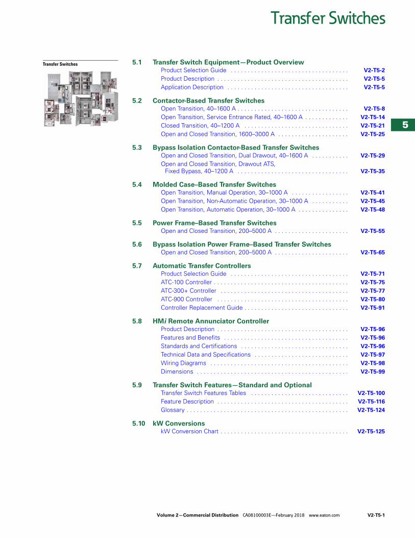
Volume 2—Commercial Distribution CA08100003E—February 2018 www.eaton.com V2-T5-1 5 5 5 5 5 5 5 5 5 5 5 5 5 5 5 5 5 5 5 5 5 5 5 5 5 5 5 5 5 5 Transfer Switches Transfer Switches 5.1 Transfer Switch Equipment—Product Overview Product Selection Guide . . . . . . . . . . . . . . . . . . . . . . . . . . . . . . . . . . . V2-T5-2 Product Description . . . . . . . . . . . . . . . . . . . . . . . . . . . . . . . . . . . . . . . V2-T5-5 Application Description . . . . . . . . . . . . . . . . . . . . . . . . . . . . . . . . . . . . V2-T5-5 5.2 Contactor-Based Transfer Switches Open Transition, 40–1600 A . . . . . . . . . . . . . . . . . . . . . . . . . . . . . . . . . V2-T5-8 Open Transition, Service Entrance Rated, 40–1600 A . . . . . . . . . . . . . V2-T5-14 Closed Transition, 40–1200 A . . . . . . . . . . . . . . . . . . . . . . . . . . . . . . . V2-T5-21 Open and Closed Transition, 1600–3000 A . . . . . . . . . . . . . . . . . . . . . V2-T5-25 5.3 Bypass Isolation Contactor-Based Transfer Switches Open and Closed Transition, Dual Drawout, 40–1600 A . . . . . . . . . . . V2-T5-29 Open and Closed Transition, Drawout ATS, Fixed Bypass, 40–1200 A . . . . . . . . . . . . . . . . . . . . . . . . . . . . . . . . . V2-T5-35 5.4 Molded Case–Based Transfer Switches Open Transition, Manual Operation, 30–1000 A . . . . . . . . . . . . . . . . . V2-T5-41 Open Transition, Non-Automatic Operation, 30–1000 A . . . . . . . . . . . V2-T5-45 Open Transition, Automatic Operation, 30–1000 A . . . . . . . . . . . . . . . V2-T5-48 5.5 Power Frame–Based Transfer Switches Open and Closed Transition, 200–5000 A . . . . . . . . . . . . . . . . . . . . . . V2-T5-55 5.6 Bypass Isolation Power Frame–Based Transfer Switches Open and Closed Transition, 200–5000 A . . . . . . . . . . . . . . . . . . . . . . V2-T5-65 5.7 Automatic Transfer Controllers Product Selection Guide . . . . . . . . . . . . . . . . . . . . . . . . . . . . . . . . . . . V2-T5-71 ATC-100 Controller . . . . . . . . . . . . . . . . . . . . . . . . . . . . . . . . . . . . . . . . V2-T5-75 ATC-300+ Controller . . . . . . . . . . . . . . . . . . . . . . . . . . . . . . . . . . . . . . V2-T5-77 ATC-900 Controller . . . . . . . . . . . . . . . . . . . . . . . . . . . . . . . . . . . . . . . V2-T5-80 Controller Replacement Guide . . . . . . . . . . . . . . . . . . . . . . . . . . . . . . . V2-T5-91 5.8 HMi Remote Annunciator Controller Product Description . . . . . . . . . . . . . . . . . . . . . . . . . . . . . . . . . . . . . . . V2-T5-96 Features and Benefits . . . . . . . . . . . . . . . . . . . . . . . . . . . . . . . . . . . . . V2-T5-96 Standards and Certifications . . . . . . . . . . . . . . . . . . . . . . . . . . . . . . . . V2-T5-96 Technical Data and Specifications . . . . . . . . . . . . . . . . . . . . . . . . . . . . V2-T5-97 Wiring Diagrams . . . . . . . . . . . . . . . . . . . . . . . . . . . . . . . . . . . . . . . . . V2-T5-98 Dimensions . . . . . . . . . . . . . . . . . . . . . . . . . . . . . . . . . . . . . . . . . . . . . V2-T5-99 5.9 Transfer Switch Features—Standard and Optional Transfer Switch Features Tables . . . . . . . . . . . . . . . . . . . . . . . . . . . . . V2-T5-100 Feature Description . . . . . . . . . . . . . . . . . . . . . . . . . . . . . . . . . . . . . . . V2-T5-116 Glossary . . . . . . . . . . . . . . . . . . . . . . . . . . . . . . . . . . . . . . . . . . . . . . . . V2-T5-124 5.10 kW Conversions kW Conversion Chart . . . . . . . . . . . . . . . . . . . . . . . . . . . . . . . . . . . . . . V2-T5-125
Transcript of Volume 2 Tab 5 - eaton.com · Volume 2—Commercial Distribution, CA08100003E Tab 5—Transfer...
Volume 2—Commercial Distribution CA08100003E—February 2018 www.eaton.com V2-T5-1
5
5
5
5
5
5
5
5
5
5
5
5
5
5
5
5
5
5
5
5
5
5
5
5
5
5
5
5
5
5
Transfer Switches
Transfer Switches 5.1 Transfer Switch Equipment—Product OverviewProduct Selection Guide . . . . . . . . . . . . . . . . . . . . . . . . . . . . . . . . . . . V2-T5-2
Product Description . . . . . . . . . . . . . . . . . . . . . . . . . . . . . . . . . . . . . . . V2-T5-5
Application Description . . . . . . . . . . . . . . . . . . . . . . . . . . . . . . . . . . . . V2-T5-5
5.2 Contactor-Based Transfer SwitchesOpen Transition, 40–1600 A . . . . . . . . . . . . . . . . . . . . . . . . . . . . . . . . . V2-T5-8
Open Transition, Service Entrance Rated, 40–1600 A . . . . . . . . . . . . . V2-T5-14
Closed Transition, 40–1200 A . . . . . . . . . . . . . . . . . . . . . . . . . . . . . . . V2-T5-21
Open and Closed Transition, 1600–3000 A . . . . . . . . . . . . . . . . . . . . . V2-T5-25
5.3 Bypass Isolation Contactor-Based Transfer SwitchesOpen and Closed Transition, Dual Drawout, 40–1600 A . . . . . . . . . . . V2-T5-29
Open and Closed Transition, Drawout ATS, Fixed Bypass, 40–1200 A . . . . . . . . . . . . . . . . . . . . . . . . . . . . . . . . . V2-T5-35
5.4 Molded Case–Based Transfer SwitchesOpen Transition, Manual Operation, 30–1000 A . . . . . . . . . . . . . . . . . V2-T5-41
Open Transition, Non-Automatic Operation, 30–1000 A . . . . . . . . . . . V2-T5-45
Open Transition, Automatic Operation, 30–1000 A . . . . . . . . . . . . . . . V2-T5-48
5.5 Power Frame–Based Transfer SwitchesOpen and Closed Transition, 200–5000 A . . . . . . . . . . . . . . . . . . . . . . V2-T5-55
5.6 Bypass Isolation Power Frame–Based Transfer SwitchesOpen and Closed Transition, 200–5000 A . . . . . . . . . . . . . . . . . . . . . . V2-T5-65
5.7 Automatic Transfer ControllersProduct Selection Guide . . . . . . . . . . . . . . . . . . . . . . . . . . . . . . . . . . . V2-T5-71
ATC-100 Controller . . . . . . . . . . . . . . . . . . . . . . . . . . . . . . . . . . . . . . . . V2-T5-75
ATC-300+ Controller . . . . . . . . . . . . . . . . . . . . . . . . . . . . . . . . . . . . . . V2-T5-77
ATC-900 Controller . . . . . . . . . . . . . . . . . . . . . . . . . . . . . . . . . . . . . . . V2-T5-80
Controller Replacement Guide . . . . . . . . . . . . . . . . . . . . . . . . . . . . . . . V2-T5-91
5.8 HMi Remote Annunciator ControllerProduct Description . . . . . . . . . . . . . . . . . . . . . . . . . . . . . . . . . . . . . . . V2-T5-96
Features and Benefits . . . . . . . . . . . . . . . . . . . . . . . . . . . . . . . . . . . . . V2-T5-96
Standards and Certifications . . . . . . . . . . . . . . . . . . . . . . . . . . . . . . . . V2-T5-96
Technical Data and Specifications . . . . . . . . . . . . . . . . . . . . . . . . . . . . V2-T5-97
Wiring Diagrams . . . . . . . . . . . . . . . . . . . . . . . . . . . . . . . . . . . . . . . . . V2-T5-98
Dimensions . . . . . . . . . . . . . . . . . . . . . . . . . . . . . . . . . . . . . . . . . . . . . V2-T5-99
5.9 Transfer Switch Features—Standard and OptionalTransfer Switch Features Tables . . . . . . . . . . . . . . . . . . . . . . . . . . . . . V2-T5-100
Feature Description . . . . . . . . . . . . . . . . . . . . . . . . . . . . . . . . . . . . . . . V2-T5-116
Glossary . . . . . . . . . . . . . . . . . . . . . . . . . . . . . . . . . . . . . . . . . . . . . . . . V2-T5-124
5.10 kW ConversionskW Conversion Chart . . . . . . . . . . . . . . . . . . . . . . . . . . . . . . . . . . . . . . V2-T5-125
Volume 2—Commercial Distribution, CA08100003E
Tab 5—Transfer SwitchesRevision date Section Change page(s) Description
02/05/2018 All All Major overhaul to complete tab, all pages revised
02/08/2018 All All Revision date changed to February 2018
Revision notes
V2-T5-2 Volume 2—Commercial Distribution CA08100003E—February 2018 www.eaton.com
5
5
5
5
5
5
5
5
5
5
5
5
5
5
5
5
5
5
5
5
5
5
5
5
5
5
5
5
5
5
5.1 Transfer Switches
Transfer Switch Equipment—Product Overview
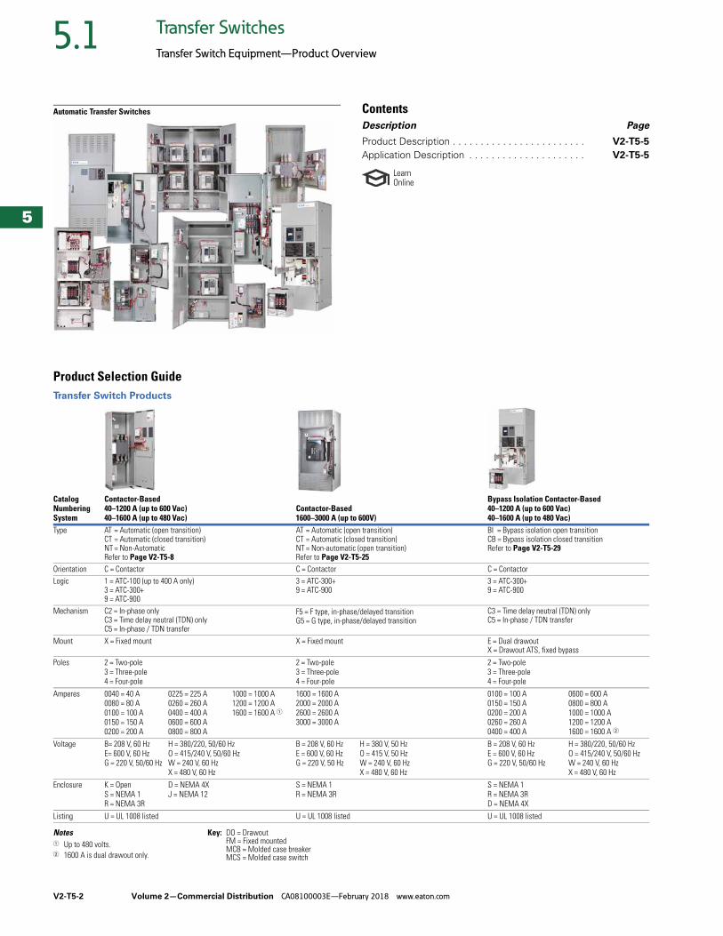
Automatic Transfer Switches ContentsDescription Page
Product Description . . . . . . . . . . . . . . . . . . . . . . . . V2-T5-5
Application Description . . . . . . . . . . . . . . . . . . . . . V2-T5-5
LearnOnline
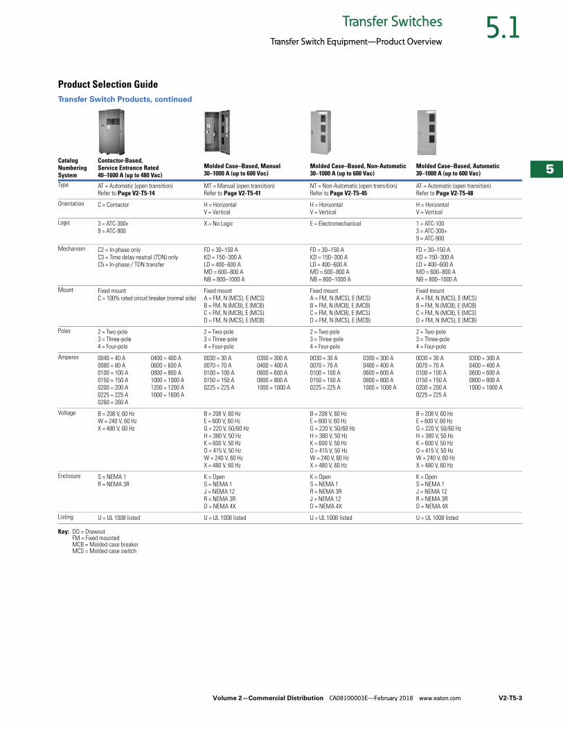
Product Selection GuideTransfer Switch Products
Notes1 Up to 480 volts.2 1600 A is dual drawout only.
Key: DO = DrawoutFM = Fixed mountedMCB = Molded case breakerMCS = Molded case switch
Catalog Numbering System
Contactor-Based40–1200 A (up to 600 Vac)40–1600 A (up to 480 Vac)
Contactor-Based1600–3000 A (up to 600V)
Bypass Isolation Contactor-Based40–1200 A (up to 600 Vac)40–1600 A (up to 480 Vac)
Type AT = Automatic (open transition)CT = Automatic (closed transition)NT = Non-AutomaticRefer to Page V2-T5-8
AT = Automatic (open transition)CT = Automatic (closed transition)NT = Non-automatic (open transition)Refer to Page V2-T5-25
BI = Bypass isolation open transitionCB = Bypass isolation closed transitionRefer to Page V2-T5-29
Orientation C = Contactor C = Contactor C = ContactorLogic 1 = ATC-100 (up to 400 A only)
3 = ATC-300+9 = ATC-900
3 = ATC-300+9 = ATC-900
3 = ATC-300+9 = ATC-900
Mechanism C2 = In-phase onlyC3 = Time delay neutral (TDN) onlyC5 = In-phase / TDN transfer
F5 = F type, in-phase/delayed transitionG5 = G type, in-phase/delayed transition
C3 = Time delay neutral (TDN) onlyC5 = In-phase / TDN transfer
Mount X = Fixed mount X = Fixed mount E = Dual drawoutX = Drawout ATS, fixed bypass
Poles 2 = Two-pole3 = Three-pole4 = Four-pole
2 = Two-pole3 = Three-pole4 = Four-pole
2 = Two-pole3 = Three-pole4 = Four-pole
Amperes 0040 = 40 A0080 = 80 A0100 = 100 A0150 = 150 A0200 = 200 A
0225 = 225 A0260 = 260 A0400 = 400 A0600 = 600 A0800 = 800 A
1000 = 1000 A1200 = 1200 A1600 = 1600 A 1
1600 = 1600 A2000 = 2000 A2600 = 2600 A3000 = 3000 A
0100 = 100 A0150 = 150 A0200 = 200 A0260 = 260 A0400 = 400 A
0600 = 600 A0800 = 800 A1000 = 1000 A1200 = 1200 A1600 = 1600 A 2
Voltage B= 208 V, 60 HzE= 600 V, 60 HzG = 220 V, 50/60 Hz
H = 380/220, 50/60 HzO = 415/240 V, 50/60 HzW = 240 V, 60 HzX = 480 V, 60 Hz
B = 208 V, 60 HzE = 600 V, 60 HzG = 220 V, 50 Hz
H = 380 V, 50 HzO = 415 V, 50 HzW = 240 V, 60 HzX = 480 V, 60 Hz
B = 208 V, 60 HzE = 600 V, 60 HzG = 220 V, 50/60 Hz
H = 380/220, 50/60 HzO = 415/240 V, 50/60 HzW = 240 V, 60 HzX = 480 V, 60 Hz
Enclosure K = OpenS = NEMA 1R = NEMA 3R
D = NEMA 4XJ = NEMA 12
S = NEMA 1R = NEMA 3R
S = NEMA 1R = NEMA 3RD = NEMA 4X
Listing U = UL 1008 listed U = UL 1008 listed U = UL 1008 listed
Volume 2—Commercial Distribution CA08100003E—February 2018 www.eaton.com V2-T5-3
5
5
5
5
5
5
5
5
5
5
5
5
5
5
5
5
5
5
5
5
5
5
5
5
5
5
5
5
5
5
5.1Transfer Switches
Transfer Switch Equipment—Product Overview
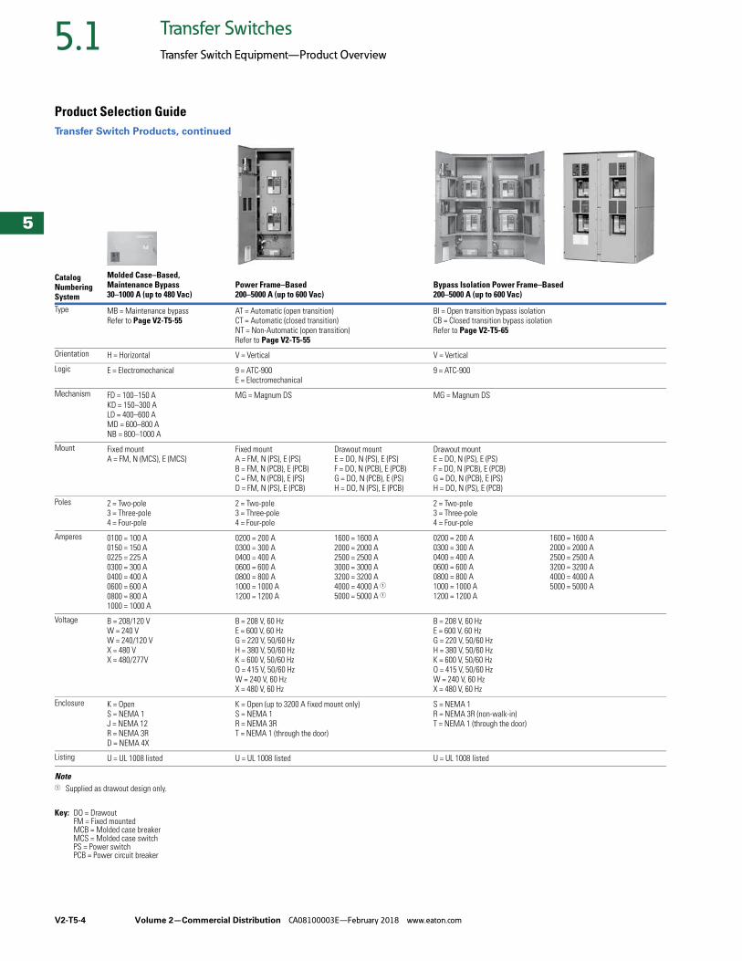
Product Selection GuideTransfer Switch Products, continued
Key: DO = DrawoutFM = Fixed mountedMCB = Molded case breakerMCS = Molded case switch
Catalog Numbering System
Contactor-Based, Service Entrance Rated40–1600 A (up to 480 Vac)
Molded Case–Based, Manual30–1000 A (up to 600 Vac)
Molded Case–Based, Non-Automatic30–1000 A (up to 600 Vac)
Molded Case–Based, Automatic30–1000 A (up to 600 Vac)
Type AT = Automatic (open transition)Refer to Page V2-T5-14
MT = Manual (open transition)Refer to Page V2-T5-41
NT = Non-Automatic (open transition)Refer to Page V2-T5-45
AT = Automatic (open transition)Refer to Page V2-T5-48
Orientation C = Contactor H = HorizontalV = Vertical
H = HorizontalV = Vertical
H = HorizontalV = Vertical
Logic 3 = ATC-300+9 = ATC-900
X = No Logic E = Electromechanical 1 = ATC-100 3 = ATC-300+ 9 = ATC-900
Mechanism C2 = In-phase onlyC3 = Time delay neutral (TDN) onlyC5 = In-phase / TDN transfer
FD = 30–150 AKD = 150–300 ALD = 400–600 AMD = 600–800 ANB = 800–1000 A
FD = 30–150 AKD = 150–300 ALD = 400–600 AMD = 600–800 ANB = 800–1000 A
FD = 30–150 AKD = 150–300 ALD = 400–600 AMD = 600–800 ANB = 800–1000 A
Mount Fixed mountC = 100% rated circuit breaker (normal side)
Fixed mountA = FM, N (MCS), E (MCS)B = FM, N (MCB), E (MCB)C = FM, N (MCB), E (MCS)D = FM, N (MCS), E (MCB)
Fixed mountA = FM, N (MCS), E (MCS)B = FM, N (MCB), E (MCB)C = FM, N (MCB), E (MCS)D = FM, N (MCS), E (MCB)
Fixed mountA = FM, N (MCS), E (MCS)B = FM, N (MCB), E (MCB)C = FM, N (MCB), E (MCS) D = FM, N (MCS), E (MCB)
Poles 2 = Two-pole3 = Three-pole4 = Four-pole
2 = Two-pole3 = Three-pole4 = Four-pole
2 = Two-pole3 = Three-pole4 = Four-pole
2 = Two-pole3 = Three-pole4 = Four-pole
Amperes 0040 = 40 A0080 = 80 A0100 = 100 A0150 = 150 A0200 = 200 A0225 = 225 A0260 = 260 A
0400 = 400 A0600 = 600 A0800 = 800 A1000 = 1000 A1200 = 1200 A1600 = 1600 A
0030 = 30 A0070 = 70 A0100 = 100 A0150 = 150 A0225 = 225 A
0300 = 300 A0400 = 400 A0600 = 600 A0800 = 800 A1000 = 1000 A
0030 = 30 A0070 = 70 A0100 = 100 A0150 = 150 A0225 = 225 A
0300 = 300 A0400 = 400 A0600 = 600 A0800 = 800 A1000 = 1000 A
0030 = 30 A0070 = 70 A0100 = 100 A0150 = 150 A0200 = 200 A0225 = 225 A
0300 = 300 A0400 = 400 A0600 = 600 A0800 = 800 A1000 = 1000 A
Voltage B = 208 V, 60 HzW = 240 V, 60 HzX = 480 V, 60 Hz
B = 208 V, 60 HzE = 600 V, 60 HzG = 220 V, 50/60 HzH = 380 V, 50 HzK = 600 V, 50 HzO = 415 V, 50 HzW = 240 V, 60 HzX = 480 V, 60 Hz
B = 208 V, 60 HzE = 600 V, 60 HzG = 220 V, 50/60 HzH = 380 V, 50 HzK = 600 V, 50 HzO = 415 V, 50 HzW = 240 V, 60 HzX = 480 V, 60 Hz
B = 208 V, 60 HzE = 600 V, 60 HzG = 220 V, 50/60 HzH = 380 V, 50 HzK = 600 V, 50 HzO = 415 V, 50 HzW = 240 V, 60 HzX = 480 V, 60 Hz
Enclosure S = NEMA 1R = NEMA 3R
K = OpenS = NEMA 1J = NEMA 12R = NEMA 3RD = NEMA 4X
K = OpenS = NEMA 1R = NEMA 3RJ = NEMA 12D = NEMA 4X
K = OpenS = NEMA 1J = NEMA 12R = NEMA 3RD = NEMA 4X
Listing U = UL 1008 listed U = UL 1008 listed U = UL 1008 listed U = UL 1008 listed
V2-T5-4 Volume 2—Commercial Distribution CA08100003E—February 2018 www.eaton.com
5
5
5
5
5
5
5
5
5
5
5
5
5
5
5
5
5
5
5
5
5
5
5
5
5
5
5
5
5
5
5.1 Transfer Switches
Transfer Switch Equipment—Product Overview
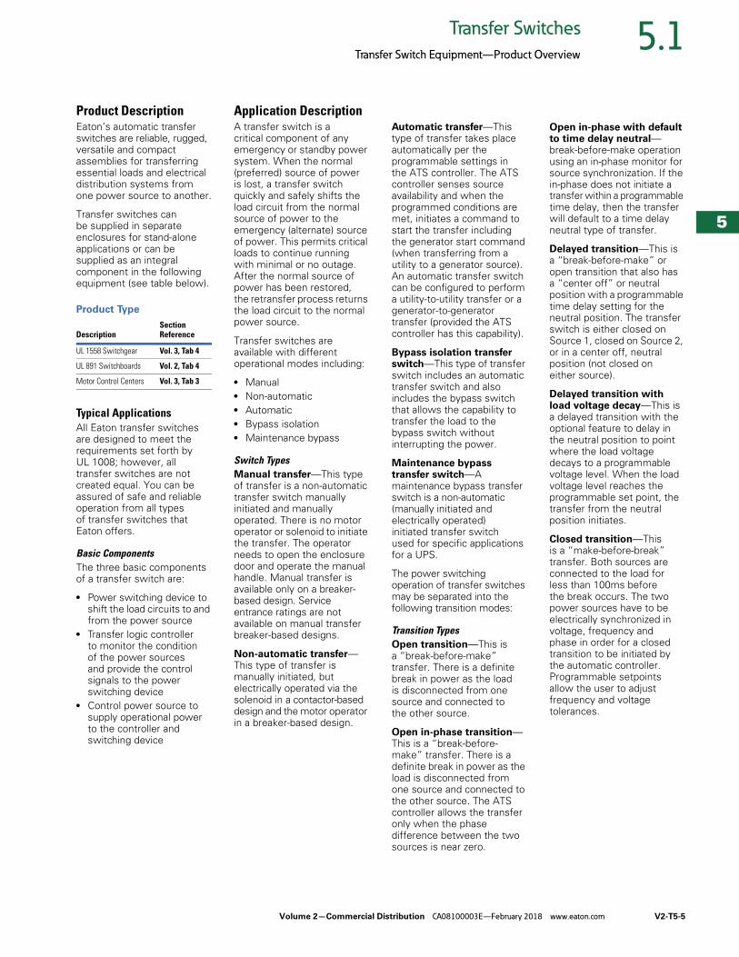
Product Selection GuideTransfer Switch Products, continued
Note1 Supplied as drawout design only.
Key: DO = DrawoutFM = Fixed mountedMCB = Molded case breakerMCS = Molded case switchPS = Power switchPCB = Power circuit breaker
Catalog Numbering System
Molded Case–Based, Maintenance Bypass30–1000 A (up to 480 Vac)
Power Frame–Based200–5000 A (up to 600 Vac)
Bypass Isolation Power Frame–Based200–5000 A (up to 600 Vac)
Type MB = Maintenance bypassRefer to Page V2-T5-55
AT = Automatic (open transition)CT = Automatic (closed transition)NT = Non-Automatic (open transition)Refer to Page V2-T5-55
BI = Open transition bypass isolationCB = Closed transition bypass isolationRefer to Page V2-T5-65
Orientation H = Horizontal V = Vertical V = Vertical
Logic E = Electromechanical 9 = ATC-900E = Electromechanical
9 = ATC-900
Mechanism FD = 100–150 AKD = 150–300 ALD = 400–600 AMD = 600–800 ANB = 800–1000 A
MG = Magnum DS MG = Magnum DS
Mount Fixed mountA = FM, N (MCS), E (MCS)
Fixed mountA = FM, N (PS), E (PS)B = FM, N (PCB), E (PCB)C = FM, N (PCB), E (PS)D = FM, N (PS), E (PCB)
Drawout mountE = DO, N (PS), E (PS)F = DO, N (PCB), E (PCB)G = DO, N (PCB), E (PS)H = DO, N (PS), E (PCB)
Drawout mountE = DO, N (PS), E (PS)F = DO, N (PCB), E (PCB)G = DO, N (PCB), E (PS)H = DO, N (PS), E (PCB)
Poles 2 = Two-pole3 = Three-pole4 = Four-pole
2 = Two-pole3 = Three-pole4 = Four-pole
2 = Two-pole3 = Three-pole4 = Four-pole
Amperes 0100 = 100 A0150 = 150 A0225 = 225 A0300 = 300 A0400 = 400 A0600 = 600 A0800 = 800 A1000 = 1000 A
0200 = 200 A0300 = 300 A0400 = 400 A0600 = 600 A0800 = 800 A1000 = 1000 A1200 = 1200 A
1600 = 1600 A2000 = 2000 A2500 = 2500 A3000 = 3000 A3200 = 3200 A4000 = 4000 A 15000 = 5000 A 1
0200 = 200 A0300 = 300 A0400 = 400 A0600 = 600 A0800 = 800 A1000 = 1000 A1200 = 1200 A
1600 = 1600 A2000 = 2000 A2500 = 2500 A3200 = 3200 A4000 = 4000 A5000 = 5000 A
Voltage B = 208/120 VW = 240 VW = 240/120 VX = 480 VX = 480/277V
B = 208 V, 60 HzE = 600 V, 60 HzG = 220 V, 50/60 HzH = 380 V, 50/60 HzK = 600 V, 50/60 HzO = 415 V, 50/60 HzW = 240 V, 60 HzX = 480 V, 60 Hz
B = 208 V, 60 HzE = 600 V, 60 HzG = 220 V, 50/60 HzH = 380 V, 50/60 HzK = 600 V, 50/60 HzO = 415 V, 50/60 HzW = 240 V, 60 HzX = 480 V, 60 Hz
Enclosure K = OpenS = NEMA 1J = NEMA 12R = NEMA 3RD = NEMA 4X
K = Open (up to 3200 A fixed mount only)S = NEMA 1R = NEMA 3RT = NEMA 1 (through the door)
S = NEMA 1R = NEMA 3R (non-walk-in)T = NEMA 1 (through the door)
Listing U = UL 1008 listed U = UL 1008 listed U = UL 1008 listed
Volume 2—Commercial Distribution CA08100003E—February 2018 www.eaton.com V2-T5-5
5
5
5
5
5
5
5
5
5
5
5
5
5
5
5
5
5
5
5
5
5
5
5
5
5
5
5
5
5
5
5.1Transfer Switches
Transfer Switch Equipment—Product Overview
Product DescriptionEaton’s automatic transfer switches are reliable, rugged, versatile and compact assemblies for transferring essential loads and electrical distribution systems from one power source to another.
Transfer switches canbe supplied in separate enclosures for stand-alone applications or can be supplied as an integral component in the following equipment (see table below).
Product Type
Typical ApplicationsAll Eaton transfer switches are designed to meet the requirements set forth by UL 1008; however, all transfer switches are not created equal. You can be assured of safe and reliable operation from all types of transfer switches that Eaton offers.
Basic ComponentsThe three basic components of a transfer switch are:
● Power switching device to shift the load circuits to and from the power source
● Transfer logic controller to monitor the condition of the power sources and provide the control signals to the power switching device
● Control power source to supply operational power to the controller and switching device
Application DescriptionA transfer switch is a critical component of any emergency or standby power system. When the normal (preferred) source of power is lost, a transfer switch quickly and safely shifts the load circuit from the normal source of power to the emergency (alternate) source of power. This permits critical loads to continue running with minimal or no outage. After the normal source of power has been restored, the retransfer process returns the load circuit to the normal power source.
Transfer switches are available with different operational modes including:
● Manual● Non-automatic● Automatic● Bypass isolation● Maintenance bypass
Switch TypesManual transfer—This type of transfer is a non-automatic transfer switch manually initiated and manually operated. There is no motor operator or solenoid to initiate the transfer. The operator needs to open the enclosure door and operate the manual handle. Manual transfer is available only on a breaker-based design. Service entrance ratings are not available on manual transfer breaker-based designs.
Non-automatic transfer—This type of transfer is manually initiated, but electrically operated via the solenoid in a contactor-based design and the motor operator in a breaker-based design.
Automatic transfer—This type of transfer takes place automatically per the programmable settings in the ATS controller. The ATS controller senses source availability and when the programmed conditions are met, initiates a command to start the transfer including the generator start command (when transferring from a utility to a generator source). An automatic transfer switch can be configured to perform a utility-to-utility transfer or a generator-to-generator transfer (provided the ATS controller has this capability).
Bypass isolation transfer switch—This type of transfer switch includes an automatic transfer switch and also includes the bypass switch that allows the capability to transfer the load to the bypass switch without interrupting the power.
Maintenance bypass transfer switch—A maintenance bypass transfer switch is a non-automatic (manually initiated and electrically operated) initiated transfer switch used for specific applications for a UPS.
The power switching operation of transfer switches may be separated into the following transition modes:
Transition TypesOpen transition—This is a “break-before-make” transfer. There is a definite break in power as the load is disconnected from one source and connected to the other source.
Open in-phase transition—This is a “break-before-make” transfer. There is a definite break in power as the load is disconnected from one source and connected to the other source. The ATS controller allows the transfer only when the phase difference between the two sources is near zero.
Open in-phase with default to time delay neutral—break-before-make operation using an in-phase monitor for source synchronization. If the in-phase does not initiate a transfer within a programmable time delay, then the transfer will default to a time delay neutral type of transfer.
Delayed transition—This is a “break-before-make” or open transition that also has a “center off” or neutral position with a programmable time delay setting for the neutral position. The transfer switch is either closed on Source 1, closed on Source 2, or in a center off, neutral position (not closed on either source).
Delayed transition with load voltage decay—This is a delayed transition with the optional feature to delay in the neutral position to point where the load voltage decays to a programmable voltage level. When the load voltage level reaches the programmable set point, the transfer from the neutral position initiates.
Closed transition—This is a “make-before-break” transfer. Both sources are connected to the load for less than 100ms before the break occurs. The two power sources have to be electrically synchronized in voltage, frequency and phase in order for a closed transition to be initiated by the automatic controller. Programmable setpoints allow the user to adjust frequency and voltage tolerances.
DescriptionSectionReference
UL 1558 Switchgear Vol. 3, Tab 4
UL 891 Switchboards Vol. 2, Tab 4
Motor Control Centers Vol. 3, Tab 3
V2-T5-6 Volume 2—Commercial Distribution CA08100003E—February 2018 www.eaton.com
5
5
5
5
5
5
5
5
5
5
5
5
5
5
5
5
5
5
5
5
5
5
5
5
5
5
5
5
5
5
5.1 Transfer Switches
Transfer Switch Equipment—Product Overview
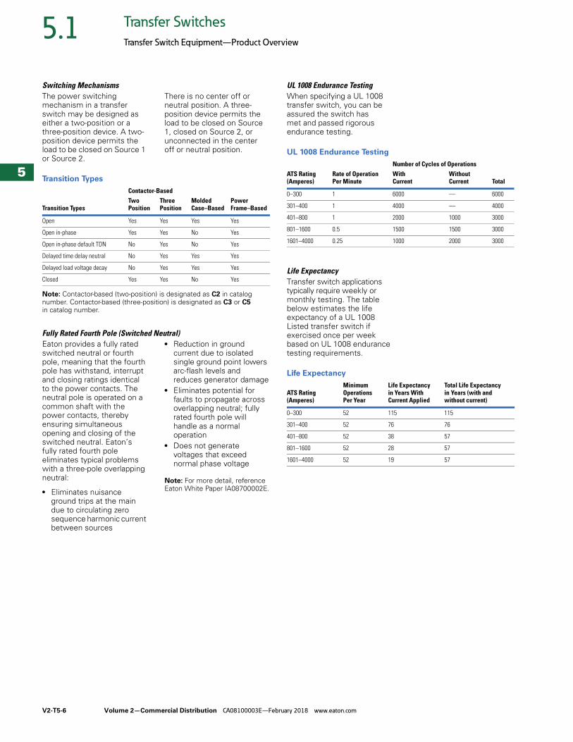
Switching MechanismsThe power switching mechanism in a transfer switch may be designed as either a two-position or a three-position device. A two-position device permits the load to be closed on Source 1 or Source 2.
There is no center off or neutral position. A three-position device permits the load to be closed on Source 1, closed on Source 2, or unconnected in the center off or neutral position.
Transition Types
Note: Contactor-based (two-position) is designated as C2 in catalog number. Contactor-based (three-position) is designated as C3 or C5 in catalog number.
Fully Rated Fourth Pole (Switched Neutral)Eaton provides a fully rated switched neutral or fourth pole, meaning that the fourth pole has withstand, interrupt and closing ratings identical to the power contacts. The neutral pole is operated on a common shaft with the power contacts, thereby ensuring simultaneous opening and closing of the switched neutral. Eaton’s fully rated fourth pole eliminates typical problems with a three-pole overlapping neutral:
● Eliminates nuisance ground trips at the main due to circulating zero sequence harmonic current between sources
● Reduction in ground current due to isolated single ground point lowers arc-flash levels and reduces generator damage
● Eliminates potential for faults to propagate across overlapping neutral; fully rated fourth pole will handle as a normal operation
● Does not generate voltages that exceed normal phase voltage
Note: For more detail, reference Eaton White Paper IA08700002E.
Contactor-Based
Transition TypesTwo Position
Three Position
MoldedCase–Based
PowerFrame–Based
Open Yes Yes Yes Yes
Open in-phase Yes Yes No Yes
Open in-phase default TDN No Yes No Yes
Delayed time delay neutral No Yes Yes Yes
Delayed load voltage decay No Yes Yes Yes
Closed Yes Yes No Yes
UL 1008 Endurance TestingWhen specifying a UL 1008 transfer switch, you can be assured the switch has met and passed rigorous endurance testing.
UL 1008 Endurance Testing
Life ExpectancyTransfer switch applications typically require weekly or monthly testing. The table below estimates the life expectancy of a UL 1008 Listed transfer switch if exercised once per week based on UL 1008 endurance testing requirements.
Life Expectancy
Number of Cycles of OperationsATS Rating(Amperes)
Rate of OperationPer Minute
With Current
WithoutCurrent Total
0–300 1 6000 — 6000
301–400 1 4000 — 4000
401–800 1 2000 1000 3000
801–1600 0.5 1500 1500 3000
1601–4000 0.25 1000 2000 3000
ATS Rating(Amperes)
Minimum OperationsPer Year
Life Expectancyin Years With Current Applied
Total Life Expectancy in Years (with and without current)
0–300 52 115 115
301–400 52 76 76
401–800 52 38 57
801–1600 52 28 57
1601–4000 52 19 57
Volume 2—Commercial Distribution CA08100003E—February 2018 www.eaton.com V2-T5-7
5
5
5
5
5
5
5
5
5
5
5
5
5
5
5
5
5
5
5
5
5
5
5
5
5
5
5
5
5
5
5.1Transfer Switches
Transfer Switch Equipment—Product Overview
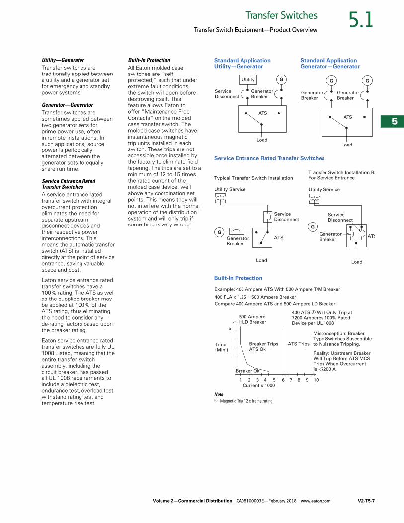
Utility—GeneratorTransfer switches are traditionally applied between a utility and a generator set for emergency and standby power systems.
Generator—GeneratorTransfer switches are sometimes applied between two generator sets for prime power use, often in remote installations. In such applications, source power is periodically alternated between the generator sets to equally share run time.
Service Entrance Rated Transfer SwitchesA service entrance rated transfer switch with integral overcurrent protection eliminates the need for separate upstream disconnect devices and their respective power interconnections. This means the automatic transfer switch (ATS) is installed directly at the point of service entrance, saving valuable space and cost.
Eaton service entrance rated transfer switches have a 100% rating. The ATS as well as the supplied breaker may be applied at 100% of the ATS rating, thus eliminating the need to consider any de-rating factors based upon the breaker rating.
Eaton service entrance rated transfer switches are fully UL 1008 Listed, meaning that the entire transfer switch assembly, including the circuit breaker, has passed all UL 1008 requirements to include a dielectric test, endurance test, overload test, withstand rating test and temperature rise test.
Built-In ProtectionAll Eaton molded case switches are “self protected,” such that under extreme fault conditions, the switch will open before destroying itself. This feature allows Eaton to offer “Maintenance-Free Contacts” on the molded case transfer switch. The molded case switches have instantaneous magnetic trip units installed in each switch. These trips are not accessible once installed by the factory to eliminate field tapering. The trips are set to a minimum of 12 to 15 times the rated current of the molded case device, well above any coordination set points. This means they will not interfere with the normal operation of the distribution system and will only trip if something is very wrong.
Standard Application Utility—Generator
Standard Application Generator—Generator
Service Entrance Rated Transfer Switches
Built-In Protection
Note1 Magnetic Trip 12 x frame rating.
ServiceDisconnect
Utility G
GeneratorBreaker
Load
ATS
G
GeneratorBreaker
G
GeneratorBreaker
Load
ATS
GeneratorBreaker
G
Load
ServiceDisconnect
ATS
Utility Service
G
GeneratorBreaker
Load
ATS
ServiceDisconnect
Utility Service
Typical Transfer Switch Installation
Transfer Switch Installation RaFor Service Entrance
400 FLA x 1.25 = 500 Ampere Breaker
Compare 400 Ampere ATS and 500 Ampere LD Breaker
Time(Min.)
5
1 2 3 4 5 6 7 8 9 10
Breaker Ok
400 ATS a Will Only Trip at 7200 Amperes 100% Rated Device per UL 1008
Breaker TripsATS Ok
ATS Trips
500 Ampere HLD Breaker
Current x 1000
Misconception: Breaker Type Switches Susceptible to Nuisance Tripping.
Example: 400 Ampere ATS With 500 Ampere T/M Breaker
Reality: Upstream Breaker Will Trip Before ATS MCS Trips When Overcurrent is <7200 A
V2-T5-8 Volume 2—Commercial Distribution CA08100003E—February 2018 www.eaton.com
5
5
5
5
5
5
5
5
5
5
5
5
5
5
5
5
5
5
5
5
5
5
5
5
5
5
5
5
5
5
5.2 Transfer Switches
Contactor-Based Transfer Switches
Contactor-Based Transfer Switch ContentsDescription Page
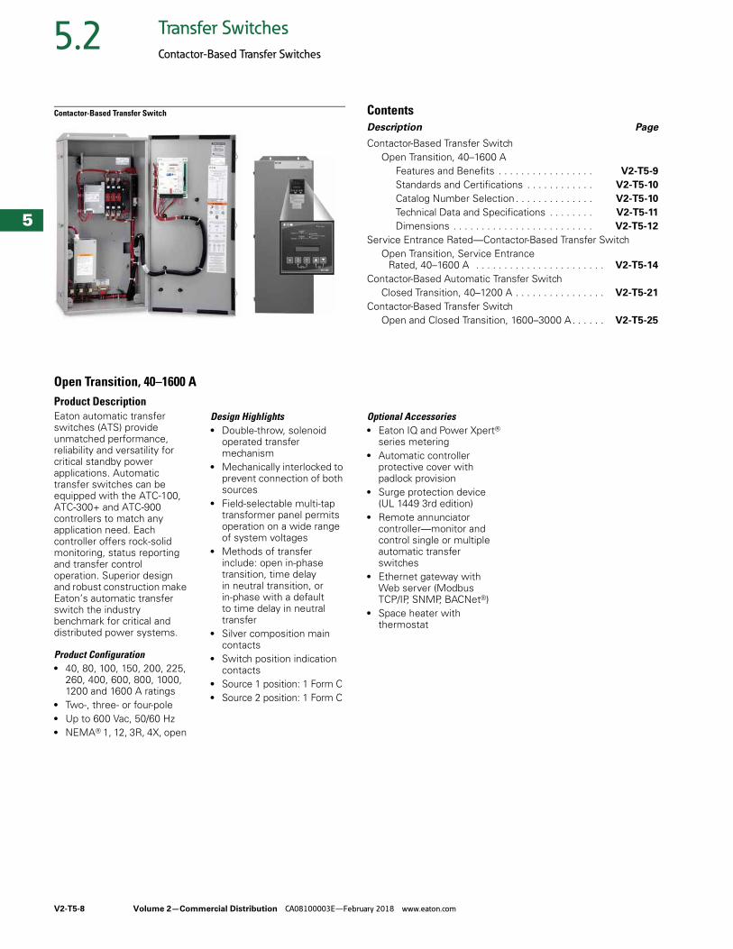
Contactor-Based Transfer SwitchOpen Transition, 40–1600 A
Features and Benefits . . . . . . . . . . . . . . . . . V2-T5-9
Standards and Certifications . . . . . . . . . . . . V2-T5-10
Catalog Number Selection . . . . . . . . . . . . . . V2-T5-10
Technical Data and Specifications . . . . . . . . V2-T5-11
Dimensions . . . . . . . . . . . . . . . . . . . . . . . . . V2-T5-12
Service Entrance Rated—Contactor-Based Transfer SwitchOpen Transition, Service Entrance
Rated, 40–1600 A . . . . . . . . . . . . . . . . . . . . . . . V2-T5-14
Contactor-Based Automatic Transfer SwitchClosed Transition, 40–1200 A . . . . . . . . . . . . . . . . V2-T5-21
Contactor-Based Transfer SwitchOpen and Closed Transition, 1600–3000 A. . . . . . V2-T5-25
Open Transition, 40–1600 AProduct DescriptionEaton automatic transfer switches (ATS) provide unmatched performance, reliability and versatility for critical standby power applications. Automatic transfer switches can be equipped with the ATC-100, ATC-300+ and ATC-900 controllers to match any application need. Each controller offers rock-solid monitoring, status reporting and transfer control operation. Superior design and robust construction make Eaton’s automatic transfer switch the industry benchmark for critical and distributed power systems.
Product Configuration● 40, 80, 100, 150, 200, 225,
260, 400, 600, 800, 1000, 1200 and 1600 A ratings
● Two-, three- or four-pole● Up to 600 Vac, 50/60 Hz● NEMA® 1, 12, 3R, 4X, open
Design Highlights● Double-throw, solenoid
operated transfer mechanism
● Mechanically interlocked to prevent connection of both sources
● Field-selectable multi-tap transformer panel permits operation on a wide range of system voltages
● Methods of transfer include: open in-phase transition, time delay in neutral transition, or in-phase with a default to time delay in neutral transfer
● Silver composition main contacts
● Switch position indication contacts
● Source 1 position: 1 Form C● Source 2 position: 1 Form C
Optional Accessories● Eaton IQ and Power Xpert®
series metering● Automatic controller
protective cover with padlock provision
● Surge protection device (UL 1449 3rd edition)
● Remote annunciator controller—monitor and control single or multiple automatic transfer switches
● Ethernet gateway with Web server (Modbus TCP/IP, SNMP, BACNet®)
● Space heater with thermostat
Volume 2—Commercial Distribution CA08100003E—February 2018 www.eaton.com V2-T5-9
5
5
5
5
5
5
5
5
5
5
5
5
5
5
5
5
5
5
5
5
5
5
5
5
5
5
5
5
5
5
5.2Transfer Switches
Contactor-Based Transfer Switches
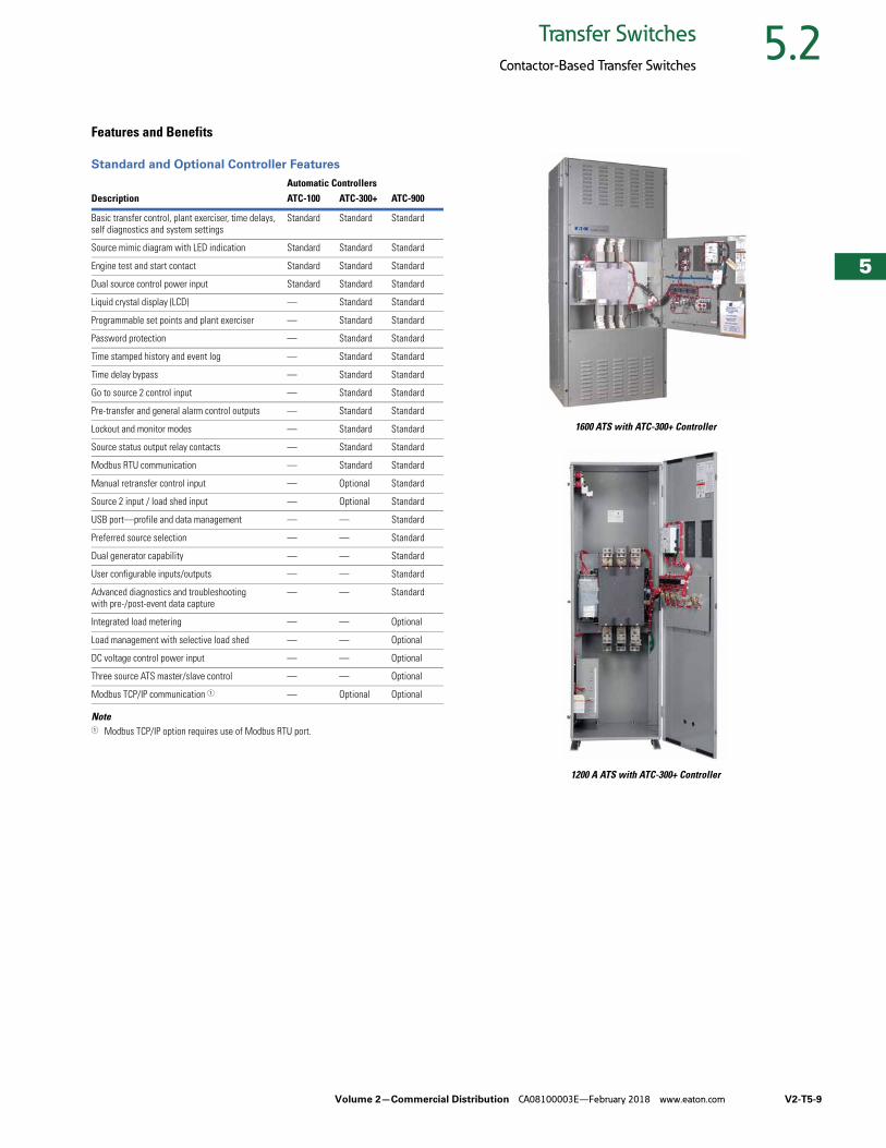
Features and Benefits
Standard and Optional Controller Features
Note1 Modbus TCP/IP option requires use of Modbus RTU port.
1600 ATS with ATC-300+ Controller
1200 A ATS with ATC-300+ Controller
Automatic ControllersDescription ATC-100 ATC-300+ ATC-900
Basic transfer control, plant exerciser, time delays, self diagnostics and system settings
Standard Standard Standard
Source mimic diagram with LED indication Standard Standard Standard
Engine test and start contact Standard Standard Standard
Dual source control power input Standard Standard Standard
Liquid crystal display (LCD) — Standard Standard
Programmable set points and plant exerciser — Standard Standard
Password protection — Standard Standard
Time stamped history and event log — Standard Standard
Time delay bypass — Standard Standard
Go to source 2 control input — Standard Standard
Pre-transfer and general alarm control outputs — Standard Standard
Lockout and monitor modes — Standard Standard
Source status output relay contacts — Standard Standard
Modbus RTU communication — Standard Standard
Manual retransfer control input — Optional Standard
Source 2 input / load shed input — Optional Standard
USB port—profile and data management — — Standard
Preferred source selection — — Standard
Dual generator capability — — Standard
User configurable inputs/outputs — — Standard
Advanced diagnostics and troubleshooting with pre-/post-event data capture
— — Standard
Integrated load metering — — Optional
Load management with selective load shed — — Optional
DC voltage control power input — — Optional
Three source ATS master/slave control — — Optional
Modbus TCP/IP communication 1 — Optional Optional
V2-T5-10 Volume 2—Commercial Distribution CA08100003E—February 2018 www.eaton.com
5
5
5
5
5
5
5
5
5
5
5
5
5
5
5
5
5
5
5
5
5
5
5
5
5
5
5
5
5
5
5.2 Transfer Switches
Contactor-Based Transfer Switches
Standards and Certifications● UL® 1008 Listed● CSA® C22.2 No. 178
Certified● Seismic Zone 4 qualified
(CBC, IBC, UBC)
● OSHPD certification
Catalog Number Selection
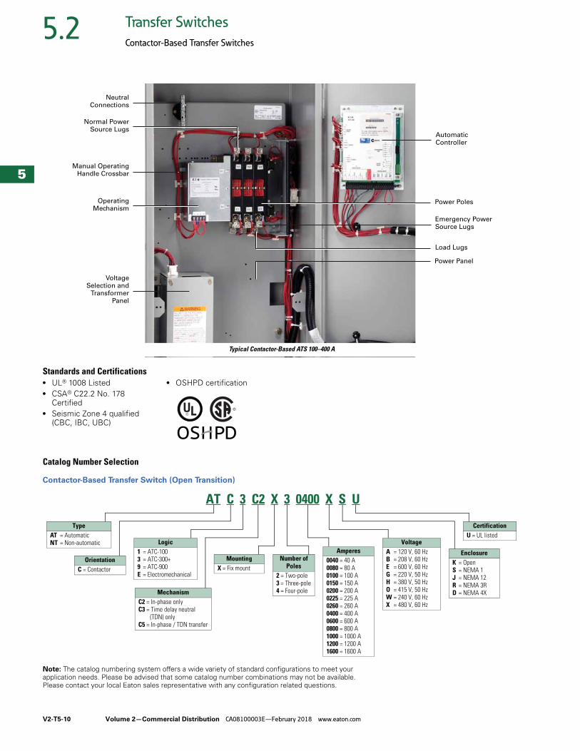
Contactor-Based Transfer Switch (Open Transition)
Note: The catalog numbering system offers a wide variety of standard configurations to meet your application needs. Please be advised that some catalog number combinations may not be available. Please contact your local Eaton sales representative with any configuration related questions.
Power Poles
Power Panel
Load Lugs
Emergency PowerSource Lugs
AutomaticController
Normal PowerSource Lugs
Manual OperatingHandle Crossbar
OperatingMechanism
NeutralConnections
VoltageSelection and
TransformerPanel
Typical Contactor-Based ATS 100–400 A
AT C 3 C2 X 3 0400 X S U
TypeAT = AutomaticNT = Non-automatic
OrientationC = Contactor
Logic1 = ATC-100 3 = ATC-300+9 = ATC-900E = Electromechanical
MechanismC2 = In-phase onlyC3 = Time delay neutral
(TDN) onlyC5 = In-phase / TDN transfer
MountingX = Fix mount
Amperes0040 = 40 A0080 = 80 A0100 = 100 A0150 = 150 A0200 = 200 A0225 = 225 A0260 = 260 A0400 = 400 A0600 = 600 A0800 = 800 A1000 = 1000 A1200 = 1200 A1600 = 1600 A
VoltageA = 120 V, 60 HzB = 208 V, 60 HzE = 600 V, 60 HzG = 220 V, 50 HzH = 380 V, 50 HzO = 415 V, 50 HzW = 240 V, 60 HzX = 480 V, 60 Hz
EnclosureK = OpenS = NEMA 1J = NEMA 12R = NEMA 3RD = NEMA 4X
CertificationU = UL listed
Number ofPoles
2 = Two-pole3 = Three-pole4 = Four-pole
Volume 2—Commercial Distribution CA08100003E—February 2018 www.eaton.com V2-T5-11
5
5
5
5
5
5
5
5
5
5
5
5
5
5
5
5
5
5
5
5
5
5
5
5
5
5
5
5
5
5
5.2Transfer Switches
Contactor-Based Transfer Switches
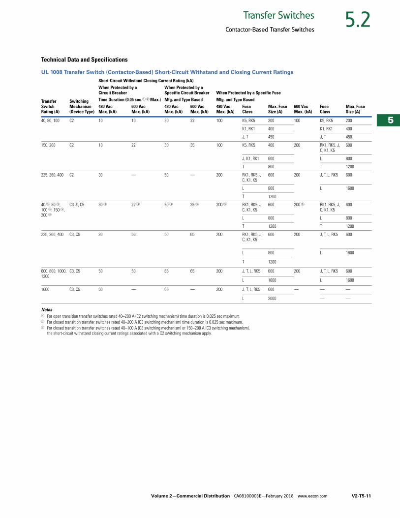
Technical Data and Specifications
UL 1008 Transfer Switch (Contactor-Based) Short-Circuit Withstand and Closing Current Ratings
Notes1 For open transition transfer switches rated 40–200 A (C2 switching mechanism) time duration is 0.025 sec maximum.2 For closed transition transfer switches rated 40–200 A (C3 switching mechanism) time duration is 0.025 sec maximum.3 For closed transition transfer switches rated 40–100 A (C3 switching mechanism) or 150–200 A (C3 switching mechanism),
the short-circuit withstand closing current ratings associated with a C2 switching mechanism apply.
Transfer Switch Rating (A)
Switching Mechanism (Device Type)
Short-Circuit Withstand Closing Current Rating (kA)When Protected by aCircuit Breaker
When Protected by aSpecific Circuit Breaker When Protected by a Specific Fuse
Time Duration (0.05 sec.1 2 Max.) Mfg. and Type Based Mfg. and Type BasedMax. Fuse Size (A)
600 Vac Max. (kA)
FuseClass
Max. Fuse Size (A)
480 Vac Max. (kA)
600 Vac Max. (kA)
480 Vac Max. (kA)
600 Vac Max. (kA)
480 Vac Max. (kA)
FuseClass
40, 80, 100 C2 10 10 30 22 100 K5, RK5 200 100 K5, RK5 200
K1, RK1 400 K1, RK1 400
J, T 450 J, T 450
150, 200 C2 10 22 30 35 100 K5, RK5 400 200 RK1, RK5, J, C, K1, K5
600
J, K1, RK1 600 L 800
T 800 T 1200
225, 260, 400 C2 30 — 50 — 200 RK1, RK5, J, C, K1, K5
600 200 J, T, L, RK5 600
L 800 L 1600
T 1200
40 3, 80 3, 100 3, 150 3, 200 3
C3 3, C5 30 3 22 3 50 3 35 3 200 3 RK1, RK5, J, C, K1, K5
600 200 3 RK1, RK5, J, C, K1, K5
600
L 800 L 800
T 1200 T 1200
225, 260, 400 C3, C5 30 50 50 65 200 RK1, RK5, J, C, K1, K5
600 200 J, T, L, RK5 600
L 800 L 1600
T 1200
600, 800, 1000, 1200
C3, C5 50 50 65 65 200 J, T, L, RK5 600 200 J, T, L, RK5 600
L 1600 L 1600
1600 C3, C5 50 — 65 — 200 J, T, L, RK5 600 — — —
L 2000 — —
V2-T5-12 Volume 2—Commercial Distribution CA08100003E—February 2018 www.eaton.com
5
5
5
5
5
5
5
5
5
5
5
5
5
5
5
5
5
5
5
5
5
5
5
5
5
5
5
5
5
5
5.2 Transfer Switches
Contactor-Based Transfer Switches
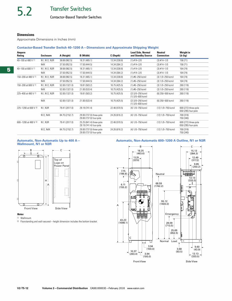
DimensionsApproximate Dimensions in Inches (mm)
Contactor-Based Transfer Switch 40–1200 A—Dimensions and Approximate Shipping Weight
Automatic, Non-Automatic Up to 400 A—Wallmount, N1 or N3R
Notes1 Wallmount.2 Floorstanding and wall-secured—height dimension includes the bottom bracket.
Automatic, Non-Automatic 600–1200 A Outline, N1 or N3R
AmpereRating Enclosure A (Height) B (Width) C (Depth)
Load Side, Normal and Standby Source
Neutral Connection
Weight inLb (kg)
40–100 at 480 V 1 N1, N12, N3R 38.68 (982.5) 18.31 (465.1) 13.34 (338.8) (1) #14–2/0 (3) #14–1/0 156 (71)
N4X 37.50 (952.5) 17.50 (444.5) 14.34 (364.2) (1) #14–2/0 (3) #14–1/0 156 (71)
40–100 at 600 V 1 N1, N12, N3R 38.68 (982.5) 18.31 (465.1) 13.34 (338.8) (1) #14–2/0 (3) #14–1/0 164 (74)
N4X 37.50 (952.5) 17.50 (444.5) 14.34 (364.2) (1) #14–2/0 (3) #14–1/0 164 (74)
150–200 at 480 V 1 N1, N12, N3R 38.68 (982.5) 18.31 (465.1) 13.34 (338.8) (1) #6–250 kcmil (3) 1/0–250 kcmil 164 (74)
N4X 37.50 (952.5) 17.50 (444.5) 14.34 (364.2) (1) #6–250 kcmil (3) 1/0–250 kcmil 164 (74)
150–200 at 600 V 1 N1, N12, N3R 52.00 (1321.0) 19.81 (503.2) 16.75 (425.5) (1) #6–250 kcmil (3) 1/0–250 kcmil 260 (118)
N4X 52.00 (1321.0) 21.00 (533.4) 16.75 (425.5) (1) #6–250 kcmil (3) 1/0–250 kcmil 260 (118)
225–400 at 480 V 1 N1, N12, N3R 52.00 (1321.0) 19.81 (503.2) 16.75 (425.5) (2) 3/0–250 kcmil(1) 3/0–600 kcmil
(6) 250–500 kcmil 260 (118)
N4X 52.00 (1321.0) 21.00 (533.4) 16.75 (425.5) (2) 3/0–250 kcmil(1) 3/0–600 kcmil
(6) 250–500 kcmil 260 (118)
225–1200 at 600 V 2 N1, N3R 79.41 (2017.0) 29.19 (741.4) 22.46 (570.5) (4) 1/0–750 kcmil (12) 1/0–750 kcmil 600 (272) three-pole650 (295) four-pole
N12, N4X 84.75 (2152.7) 29.00 (737.0) three-pole29.00 (737.0) four-pole
24.26 (616.2) (4) 1/0–750 kcmil (12) 1/0–750 kcmil 700 (318)750 (340)
600–1200 at 480 V 2 N1, N3R 79.41 (2017.0) 25.25 (641.4) three-pole29.19 (741.4) four-pole
22.46 (570.5) (4) 1/0–750 kcmil (12) 1/0–750 kcmil 600 (272) three-pole650 (295) four-pole
N12, N4X 84.75 (2152.7) 29.00 (737.0) three-pole29.00 (737.0) four-pole
24.26 (616.2) (4) 1/0–750 kcmil (12) 1/0–750 kcmil 700 (318)750 (340)
B
G
A
H
C
Front View Side View
Top ofLugs onPower Panel
Front View Side View
10.37(263.4)
3.94(100.0)
43.23(1098.1)
13.29(337.6)
9.60(43.9)
25.69(652.5)
28.09(713.5)
55.12(1400.0)
3.68(93.5)
13.13(333.5)
13.13(333.5)
18.25(463.6)
6.11(155.2)
7.75(196.8)
68.59(1742.2)
9.85(250.2)
12.49(317.2)
15.13(384.3)
A
B C
Emergency
LoadNormal
Neutral
C
A
3.94(100.0)
Volume 2—Commercial Distribution CA08100003E—February 2018 www.eaton.com V2-T5-13
5
5
5
5
5
5
5
5
5
5
5
5
5
5
5
5
5
5
5
5
5
5
5
5
5
5
5
5
5
5
5.2Transfer Switches
Contactor-Based Transfer Switches
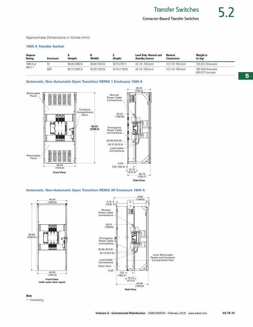
Approximate Dimensions in Inches (mm)
1600 A Transfer Switch
Automatic, Non-Automatic Open Transition NEMA 1 Enclosure 1600 A
Automatic, Non-Automatic Open Transition NEMA 3R Enclosure 1600 A
Note1 Freestanding.
AmpereRating Enclosure
A (Height)
B (Width)
C (Depth)
Load Side, Normal and Standby Source
NeutralConnection
Weight inLb (kg)
1600 A at 480 V 1
N1 90.00 (2286.0) 40.00 (1016.0) 28.73 (729.7) (4) 1/0–750 kcmil (12) 1/0–750 kcmil 730 (331) three-pole
N3R 90.72 (2304.3) 40.35 (1024.9) 43.34 (1100.8) (4) 1/0–750 kcmil (12) 1/0–750 kcmil 780 (354) three-pole 830 (377) four-pole
90.00(2286.0)
40.00(1016.0)
90.00(2286.0)
28.73(729.7)
10.72(272.3)
7.22 (183.4)
0.00
24.13 (612.9)
Load CableConnections
EmergencyPower CableConnections
26.49 (672.8)
62.51(1587.8)
NormalPower CableConnections
29.22(742.2)
Side View
Front View
RemovablePanel
RemovablePanel
ContactorCompartment
Door
40.00(1016.0)
Side View
Front View(with outer door open)
90.69(2303.5)
40.35(1024.9)
43.34(1100.8)
10.72(272.3)
7.22(183.4)
0.00
47.59(1208.8)
3.14(79.8)
24.13 (612.9)
Outer Door
Inner RemovablePanels and ContactorCompartment DoorLoad Cable
Connections
EmergencyPower CableConnections
26.49 (672.8)
62.51(1587.8)
NormalPower CableConnections
V2-T5-14 Volume 2—Commercial Distribution CA08100003E—February 2018 www.eaton.com
5
5
5
5
5
5
5
5
5
5
5
5
5
5
5
5
5
5
5
5
5
5
5
5
5
5
5
5
5
5
5.2 Transfer Switches
Contactor-Based Transfer Switches
Service Entrance Rated—Contactor-Based Transfer Switch ContentsDescription Page
Contactor-Based Transfer SwitchOpen Transition, 40–1600 A . . . . . . . . . . . . . . . . . V2-T5-8
Service Entrance Rated—Contactor-Based Transfer SwitchOpen Transition, Service Entrance Rated, 40–1600 A
Features and Benefits . . . . . . . . . . . . . . . . . V2-T5-15
Standards and Certifications . . . . . . . . . . . . V2-T5-18
Catalog Number Selection . . . . . . . . . . . . . V2-T5-18
Technical Data and Specifications . . . . . . . . V2-T5-19
Dimensions . . . . . . . . . . . . . . . . . . . . . . . . . V2-T5-19
Contactor-Based Automatic Transfer SwitchClosed Transition, 40–1200 A . . . . . . . . . . . . . . . . V2-T5-21
Contactor-Based Transfer SwitchOpen and Closed Transition, 1600–3000 A. . . . . . V2-T5-25
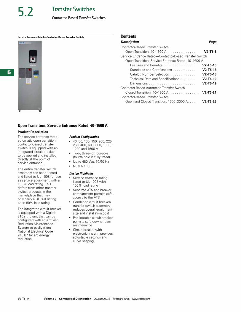
Open Transition, Service Entrance Rated, 40–1600 AProduct DescriptionThe service entrance rated automatic open transition contactor-based transfer switch is equipped with an integrated circuit breaker to be applied and installed directly at the point of service entrance.
The entire transfer switch assembly has been tested and listed to UL 1008 for use as service equipment with a 100% load rating. This differs from other transfer switch products in the marketplace that may only carry a UL 891 listing or an 80% load rating.
The integrated circuit breaker is equipped with a Digitrip 310+ trip unit that can be configured with an Arcflash Reduction Maintenance System to easily meet National Electrical Code 240.87 for arc energy reduction.
Product Configuration● 40, 80, 100, 150, 200, 225,
260, 400, 600, 800, 1000, 1200 and 1600 A
● Two-, three- or four-pole (fourth pole is fully rated)
● Up to 480 Vac, 50/60 Hz● NEMA 1, 3R
Design Highlights● Service entrance rating
listed to UL 1008 with 100% load rating
● Separate ATS and breaker compartment permits safe access to the ATS
● Combined circuit breaker/transfer switch assembly reduces overall equipment size and installation cost
● Pad-lockable circuit breaker permits safe downstream maintenance
● Circuit breaker with electronic trip unit provides adjustable settings and curve shaping
Volume 2—Commercial Distribution CA08100003E—February 2018 www.eaton.com V2-T5-15
5
5
5
5
5
5
5
5
5
5
5
5
5
5
5
5
5
5
5
5
5
5
5
5
5
5
5
5
5
5
5.2Transfer Switches
Contactor-Based Transfer Switches
Features and Benefits
Standard Features—with ATC-300+ Controller● Auxiliary relay contacts:
● Source 1 present 2NO and 2NC
● Source 2 present 2NO and 2NC
● Switch position indication contacts:● Source 1 position 1NO
and 1NC● Source 2 position 1NO
and 1NC● Source 1 and Source 2
sensing:● Undervoltage/
underfrequency● Overvoltage/
overfrequency● Three-phase rotation
protection● Three-phase voltage
unbalance● Pretransfer signal contacts
1NO/1NC (with three-position mechanism)
● Go to emergency (Source 2)● Seven field-programmable
time delays● LCD-based display for
programming, system diagnostics and Help message display
● Mimic diagram with source available and connected LED indication
● Time-stamped history log● System TEST pushbutton● Programmable plant
exerciser—OFF, daily, 7-, 14-, 28-day interval selectable run time 0–600 minutes no load/load with fail-safe
● Modbus® RTU via RS-485● Source 1 Eaton Series G
breaker with 310+ electronic trip unit with LSI
● Deadfront compartment for breaker
● Series G breaker with shunt trip
● Separate switch compartment
Optional Features● Available surge
suppression device for power/controller, engine start circuit, phone and cable connections
● Space heater with thermostat
● Eaton IQ and Power Xpert series metering
● Open in-phase transition, time delay neutral or in-phase with a default to time delay neutral transfer
● ATC-300+ and ATC-900 controllers available
● Source 2 inhibit● Manual retransfer to
normal● Remote annunciator with
control● Ethernet communication
(PXG 900 Gateway)● Breaker with LSIG
electronic trip units● Breaker with Arcflash
Reduction Maintenance System
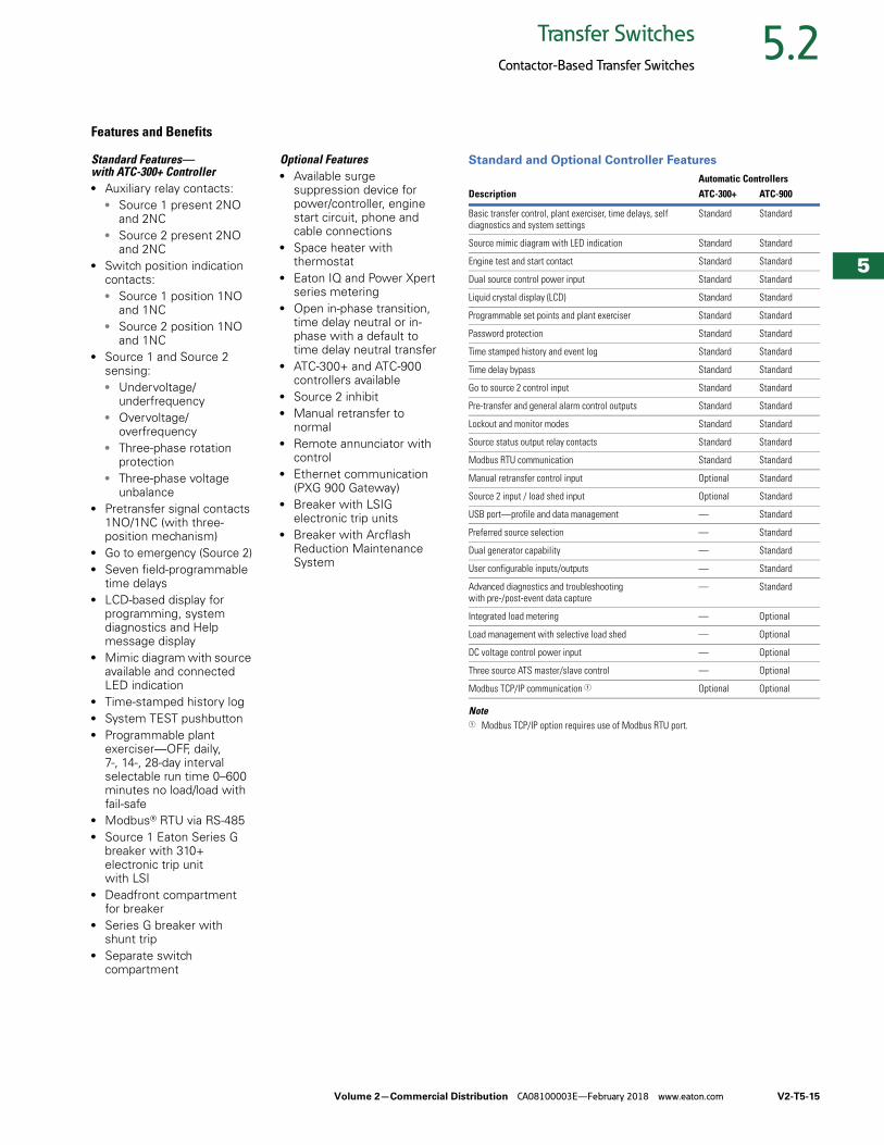
Standard and Optional Controller Features
Note1 Modbus TCP/IP option requires use of Modbus RTU port.
Automatic ControllersDescription ATC-300+ ATC-900
Basic transfer control, plant exerciser, time delays, self diagnostics and system settings
Standard Standard
Source mimic diagram with LED indication Standard Standard
Engine test and start contact Standard Standard
Dual source control power input Standard Standard
Liquid crystal display (LCD) Standard Standard
Programmable set points and plant exerciser Standard Standard
Password protection Standard Standard
Time stamped history and event log Standard Standard
Time delay bypass Standard Standard
Go to source 2 control input Standard Standard
Pre-transfer and general alarm control outputs Standard Standard
Lockout and monitor modes Standard Standard
Source status output relay contacts Standard Standard
Modbus RTU communication Standard Standard
Manual retransfer control input Optional Standard
Source 2 input / load shed input Optional Standard
USB port—profile and data management — Standard
Preferred source selection — Standard
Dual generator capability — Standard
User configurable inputs/outputs — Standard
Advanced diagnostics and troubleshooting with pre-/post-event data capture
— Standard
Integrated load metering — Optional
Load management with selective load shed — Optional
DC voltage control power input — Optional
Three source ATS master/slave control — Optional
Modbus TCP/IP communication 1 Optional Optional
V2-T5-16 Volume 2—Commercial Distribution CA08100003E—February 2018 www.eaton.com
5
5
5
5
5
5
5
5
5
5
5
5
5
5
5
5
5
5
5
5
5
5
5
5
5
5
5
5
5
5
5.2 Transfer Switches
Contactor-Based Transfer Switches
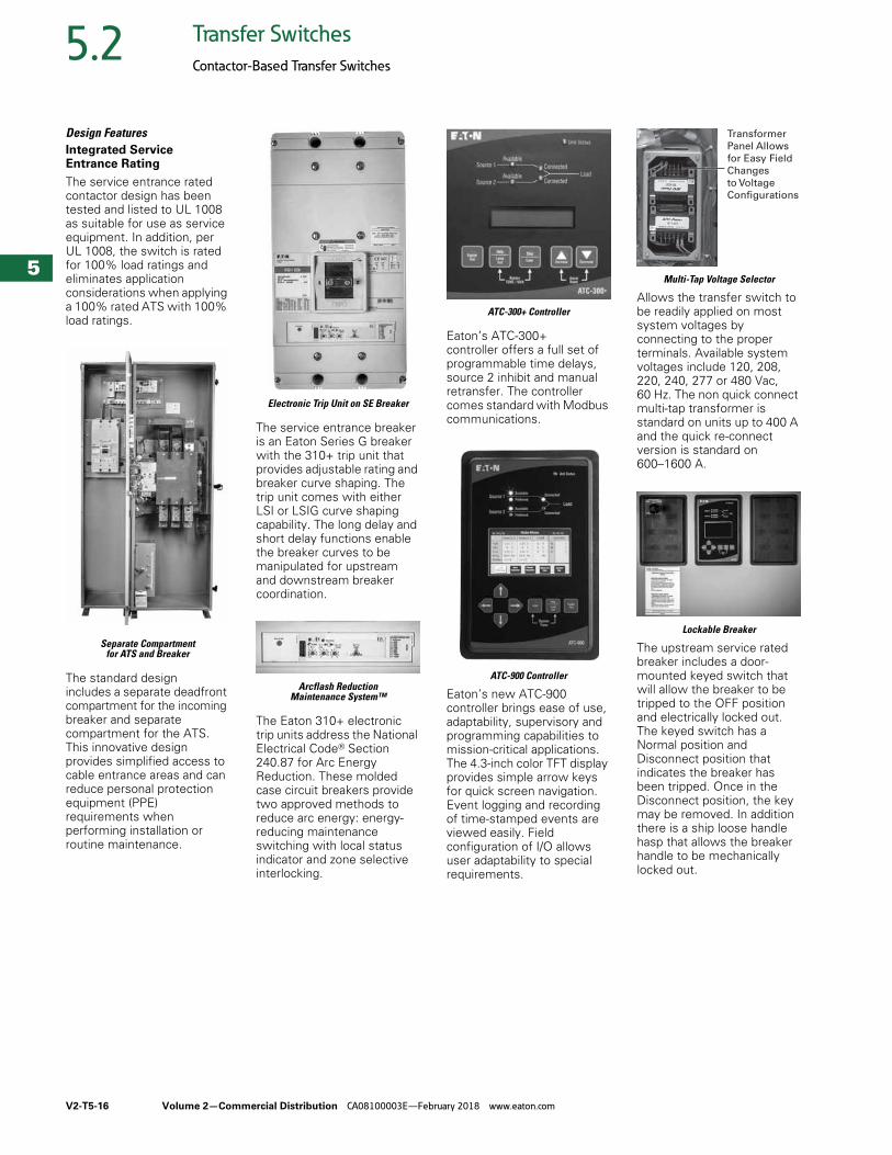
Design FeaturesIntegrated Service Entrance Rating
The service entrance rated contactor design has been tested and listed to UL 1008 as suitable for use as service equipment. In addition, per UL 1008, the switch is rated for 100% load ratings and eliminates application considerations when applying a 100% rated ATS with 100% load ratings.
Separate Compartment for ATS and Breaker
The standard design includes a separate deadfront compartment for the incoming breaker and separate compartment for the ATS. This innovative design provides simplified access to cable entrance areas and can reduce personal protection equipment (PPE) requirements when performing installation or routine maintenance.
Electronic Trip Unit on SE Breaker
The service entrance breaker is an Eaton Series G breaker with the 310+ trip unit that provides adjustable rating and breaker curve shaping. The trip unit comes with either LSI or LSIG curve shaping capability. The long delay and short delay functions enable the breaker curves to be manipulated for upstream and downstream breaker coordination.
Arcflash Reduction Maintenance System™
The Eaton 310+ electronic trip units address the National Electrical Code® Section 240.87 for Arc Energy Reduction. These molded case circuit breakers provide two approved methods to reduce arc energy: energy-reducing maintenance switching with local status indicator and zone selective interlocking.
ATC-300+ Controller
Eaton’s ATC-300+ controller offers a full set of programmable time delays, source 2 inhibit and manual retransfer. The controller comes standard with Modbus communications.
ATC-900 Controller
Eaton’s new ATC-900 controller brings ease of use, adaptability, supervisory and programming capabilities to mission-critical applications. The 4.3-inch color TFT display provides simple arrow keys for quick screen navigation. Event logging and recording of time-stamped events are viewed easily. Field configuration of I/O allows user adaptability to special requirements.
Multi-Tap Voltage Selector
Allows the transfer switch to be readily applied on most system voltages by connecting to the proper terminals. Available system voltages include 120, 208, 220, 240, 277 or 480 Vac, 60 Hz. The non quick connect multi-tap transformer is standard on units up to 400 A and the quick re-connect version is standard on 600–1600 A.
Lockable Breaker
The upstream service rated breaker includes a door-mounted keyed switch that will allow the breaker to be tripped to the OFF position and electrically locked out. The keyed switch has a Normal position and Disconnect position that indicates the breaker has been tripped. Once in the Disconnect position, the key may be removed. In addition there is a ship loose handle hasp that allows the breaker handle to be mechanically locked out.
Transformer
Panel Allows
for Easy Field
Changes
to Voltage
Configurations
Volume 2—Commercial Distribution CA08100003E—February 2018 www.eaton.com V2-T5-17
5
5
5
5
5
5
5
5
5
5
5
5
5
5
5
5
5
5
5
5
5
5
5
5
5
5
5
5
5
5
5.2Transfer Switches
Contactor-Based Transfer Switches
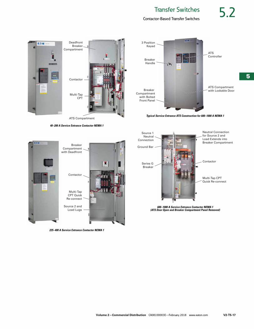
40–200 A Service Entrance Contactor NEMA 1
225–400 A Service Entrance Contactor NEMA 1
Typical Service Entrance ATS Construction for 600–1000 A NEMA 1
600–1000 A Service Entrance Contactor NEMA 1 (ATS Door Open and Breaker Compartment Panel Removed)
Deadfront
Breaker
Compartment
Contactor
Multi-Tap
CPT
ATS Compartment
Breaker
Compartment
with Deadfront
Multi-Tap
CPT Quick
Re-connect
Source 2 and
Load Lugs
Contactor
3 Position
Keyed
ATS
ControllerBreaker
Handle
Breaker
Compartment
with Bolted
Front Panel
ATS Compartment
with Lockable Door
Source 1
Neutral
Connection
Neutral Connection
for Source 2 and
Load Extends into
Breaker Compartment
Contactor
Multi-Tap CPT
Quick Re-connect
Ground Bar
Series G
Breaker
V2-T5-18 Volume 2—Commercial Distribution CA08100003E—February 2018 www.eaton.com
5
5
5
5
5
5
5
5
5
5
5
5
5
5
5
5
5
5
5
5
5
5
5
5
5
5
5
5
5
5
5.2 Transfer Switches
Contactor-Based Transfer Switches
Standards and Certifications● UL 1008 Listed● CSA C22.2 No. 178
Certified
Catalog Number Selection
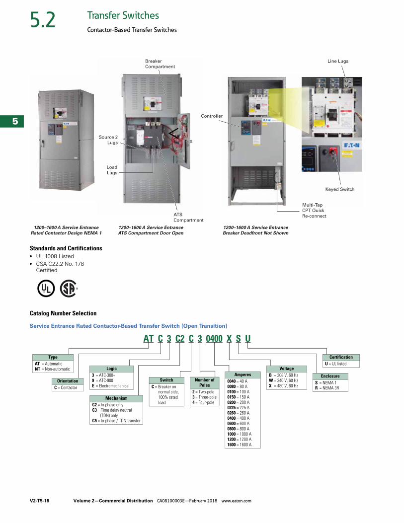
Service Entrance Rated Contactor-Based Transfer Switch (Open Transition)
Breaker
Compartment
Source 2
Lugs
Load
Lugs
ATS
Compartment
Line Lugs
Keyed Switch
Multi-Tap
CPT Quick
Re-connect
Controller
1200–1600 A Service Entrance
Rated Contactor Design NEMA 1
1200–1600 A Service Entrance
ATS Compartment Door Open
1200–1600 A Service Entrance
Breaker Deadfront Not Shown
AT C 3 C2 C 3 0400 X S U
TypeAT = AutomaticNT = Non-automatic
OrientationC = Contactor
Logic3 = ATC-300+9 = ATC-900E = Electromechanical
MechanismC2 = In-phase onlyC3 = Time delay neutral
(TDN) onlyC5 = In-phase / TDN transfer
SwitchC = Breaker on
normal side, 100% rated load
Amperes0040 = 40 A0080 = 80 A0100 = 100 A0150 = 150 A0200 = 200 A0225 = 225 A0260 = 260 A0400 = 400 A0600 = 600 A0800 = 800 A1000 = 1000 A1200 = 1200 A1600 = 1600 A
VoltageB = 208 V, 60 HzW = 240 V, 60 HzX = 480 V, 60 Hz
EnclosureS = NEMA 1R = NEMA 3R
CertificationU = UL listed
Number ofPoles
2 = Two-pole3 = Three-pole4 = Four-pole
Volume 2—Commercial Distribution CA08100003E—February 2018 www.eaton.com V2-T5-19
5
5
5
5
5
5
5
5
5
5
5
5
5
5
5
5
5
5
5
5
5
5
5
5
5
5
5
5
5
5
5.2Transfer Switches
Contactor-Based Transfer Switches
Technical Data and Specifications
UL 1008 Short-Circuit Withstand and Close-On Current Ratings (kA)
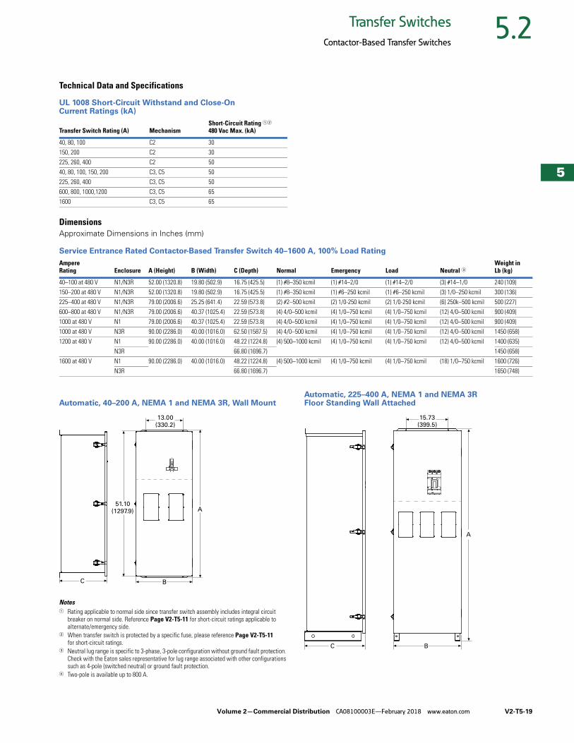
DimensionsApproximate Dimensions in Inches (mm)
Service Entrance Rated Contactor-Based Transfer Switch 40–1600 A, 100% Load Rating
Automatic, 40–200 A, NEMA 1 and NEMA 3R, Wall Mount
Notes1 Rating applicable to normal side since transfer switch assembly includes integral circuit
breaker on normal side. Reference Page V2-T5-11 for short-circuit ratings applicable to alternate/emergency side.
2 When transfer switch is protected by a specific fuse, please reference Page V2-T5-11 for short-circuit ratings.
3 Neutral lug range is specific to 3-phase, 3-pole configuration without ground fault protection. Check with the Eaton sales representative for lug range associated with other configurations such as 4-pole (switched neutral) or ground fault protection.
4 Two-pole is available up to 800 A.
Automatic, 225–400 A, NEMA 1 and NEMA 3R Floor Standing Wall Attached
Transfer Switch Rating (A) MechanismShort-Circuit Rating 12
480 Vac Max. (kA)
40, 80, 100 C2 30
150, 200 C2 30
225, 260, 400 C2 50
40, 80, 100, 150, 200 C3, C5 50
225, 260, 400 C3, C5 50
600, 800, 1000,1200 C3, C5 65
1600 C3, C5 65
AmpereRating Enclosure A (Height) B (Width) C (Depth) Normal Emergency Load Neutral 3
Weight inLb (kg)
40–100 at 480 V N1/N3R 52.00 (1320.8) 19.80 (502.9) 16.75 (425.5) (1) #8–350 kcmil (1) #14–2/0 (1) #14–2/0 (3) #14–1/0 240 (109)
150–200 at 480 V N1/N3R 52.00 (1320.8) 19.80 (502.9) 16.75 (425.5) (1) #8–350 kcmil (1) #6–250 kcmil (1) #6–250 kcmil (3) 1/0–250 kcmil 300 (136)
225–400 at 480 V N1/N3R 79.00 (2006.6) 25.25 (641.4) 22.59 (573.8) (2) #2–500 kcmil (2) 1/0-250 kcmil (2) 1/0-250 kcmil (6) 250k–500 kcmil 500 (227)
600–800 at 480 V N1/N3R 79.00 (2006.6) 40.37 (1025.4) 22.59 (573.8) (4) 4/0–500 kcmil (4) 1/0–750 kcmil (4) 1/0–750 kcmil (12) 4/0–500 kcmil 900 (409)
1000 at 480 V N1 79.00 (2006.6) 40.37 (1025.4) 22.59 (573.8) (4) 4/0–500 kcmil (4) 1/0–750 kcmil (4) 1/0–750 kcmil (12) 4/0–500 kcmil 900 (409)
1000 at 480 V N3R 90.00 (2286.0) 40.00 (1016.0) 62.50 (1587.5) (4) 4/0–500 kcmil (4) 1/0–750 kcmil (4) 1/0–750 kcmil (12) 4/0–500 kcmil 1450 (658)
1200 at 480 V N1 90.00 (2286.0) 40.00 (1016.0) 48.22 (1224.8) (4) 500–1000 kcmil (4) 1/0–750 kcmil (4) 1/0–750 kcmil (12) 4/0–500 kcmil 1400 (635)
N3R 66.80 (1696.7) 1450 (658)
1600 at 480 V N1 90.00 (2286.0) 40.00 (1016.0) 48.22 (1224.8) (4) 500–1000 kcmil (4) 1/0–750 kcmil (4) 1/0–750 kcmil (18) 1/0–750 kcmil 1600 (726)
N3R 66.80 (1696.7) 1650 (748)
A
13.00(330.2)
BC
51.10(1297.9)
15.73(399.5)
A
BC
V2-T5-20 Volume 2—Commercial Distribution CA08100003E—February 2018 www.eaton.com
5
5
5
5
5
5
5
5
5
5
5
5
5
5
5
5
5
5
5
5
5
5
5
5
5
5
5
5
5
5
5.2 Transfer Switches
Contactor-Based Transfer Switches
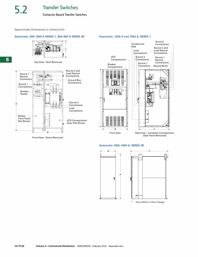
Approximate Dimensions in Inches (mm)
Automatic, 600–1000 A NEMA 1, 600–800 A NEMA 3R Automatic, 1200 A and 1600 A, NEMA 1
Automatic 1000–1600 A, NEMA 3R
ABC
ABC
Front View—Doors Removed
Source 1NeutralConnection
Source 2 andLoad NeutralConnections
Ground BusConnections
Top View—Roof Removed
BreakerSwitch
Source 1Connections
C
A
B
Bolted Front Panel Not Shown
Source 2ConnectionsLoadConnections
ATS CompartmentDoor Not Shown
B
A
C
Side View—Contactor Compartment(Side Panel Removed)
Front View
Source 2Connections
LoadConnections
GroundConnections
Source 1NeutralConnections
Source 2 andLoad NeutralConnections
Neutral BondSource 1Connection
TransformerPack
BreakerCompartment
ATSCompartment
A
B C
Door Within a Door DesignD
Volume 2—Commercial Distribution CA08100003E—February 2018 www.eaton.com V2-T5-21
5
5
5
5
5
5
5
5
5
5
5
5
5
5
5
5
5
5
5
5
5
5
5
5
5
5
5
5
5
5
5.2Transfer Switches
Contactor-Based Transfer Switches
Contactor-Based Automatic Transfer Switch ContentsDescription Page
Contactor-Based Transfer SwitchOpen Transition, 40–1600 A . . . . . . . . . . . . . . . . V2-T5-8
Service Entrance Rated—Contactor-Based Transfer SwitchOpen Transition, Service Entrance
Rated, 40–1600 A . . . . . . . . . . . . . . . . . . . . . . V2-T5-14
Contactor-Based Automatic Transfer SwitchClosed Transition, 40–1200 A
Features and Benefits . . . . . . . . . . . . . . . . . V2-T5-21
Standards and Certifications . . . . . . . . . . . . V2-T5-22
Catalog Number Selection . . . . . . . . . . . . . V2-T5-23
Technical Data and Specifications . . . . . . . . V2-T5-23
Dimensions . . . . . . . . . . . . . . . . . . . . . . . . . V2-T5-24
Contactor-Based Transfer SwitchOpen and Closed Transition, 1600–3000 A . . . . . V2-T5-25
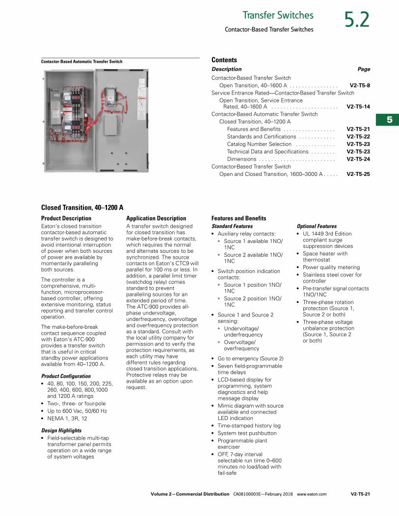
Closed Transition, 40–1200 AProduct DescriptionEaton’s closed transition contactor-based automatic transfer switch is designed to avoid intentional interruption of power when both sources of power are available by momentarily paralleling both sources.
The controller is a comprehensive, multi-function, microprocessor-based controller, offering extensive monitoring, status reporting and transfer control operation.
The make-before-break contact sequence coupled with Eaton’s ATC-900 provides a transfer switch that is useful in critical standby power applications available from 40–1200 A.
Product Configuration● 40, 80, 100, 150, 200, 225,
260, 400, 600, 800,1000 and 1200 A ratings
● Two-, three- or four-pole● Up to 600 Vac, 50/60 Hz● NEMA 1, 3R, 12
Design Highlights● Field-selectable multi-tap
transformer panel permits operation on a wide range of system voltages
Application DescriptionA transfer switch designed for closed transition has make-before-break contacts, which requires the normal and alternate sources to be synchronized. The source contacts on Eaton’s CTC9 will parallel for 100 ms or less. In addition, a parallel limit timer (watchdog relay) comes standard to prevent paralleling sources for an extended period of time. The ATC-900 provides all-phase undervoltage, underfrequency, overvoltage and overfrequency protection as a standard. Consult with the local utility company for permission and to verify the protection requirements, as each utility may have different rules regarding closed transition applications. Protective relays may be available as an option upon request.
Features and BenefitsStandard Features● Auxiliary relay contacts:
● Source 1 available 1NO/1NC
● Source 2 available 1NO/1NC
● Switch position indication contacts:● Source 1 position 1NO/
1NC● Source 2 position 1NO/
1NC
● Source 1 and Source 2 sensing:● Undervoltage/
underfrequency● Overvoltage/
overfrequency
● Go to emergency (Source 2)● Seven field-programmable
time delays● LCD-based display for
programming, system diagnostics and help message display
● Mimic diagram with source available and connected LED indication
● Time-stamped history log● System test pushbutton● Programmable plant
exerciser● OFF, 7-day interval
selectable run time 0–600 minutes no load/load with fail-safe
Optional Features● UL 1449 3rd Edition
compliant surge suppression devices
● Space heater with thermostat
● Power quality metering● Stainless steel cover for
controller● Pre-transfer signal contacts
1NO/1NC● Three-phase rotation
protection (Source 1, Source 2 or both)
● Three-phase voltage unbalance protection (Source 1, Source 2 or both)
V2-T5-22 Volume 2—Commercial Distribution CA08100003E—February 2018 www.eaton.com
5
5
5
5
5
5
5
5
5
5
5
5
5
5
5
5
5
5
5
5
5
5
5
5
5
5
5
5
5
5
5.2 Transfer Switches
Contactor-Based Transfer Switches
Standard and Optional Controller Features
Note1 Modbus TCP/IP option requires use of Modbus RTU port.
Automatic Controller
Description ATC-900
Basic transfer control, plant exerciser, time delays, self diagnostics and system settings
Standard
Source mimic diagram with LED indication Standard
Engine test and start contact Standard
Dual source control power input Standard
Liquid crystal display (LCD) Standard
Programmable set points and plant exerciser Standard
Password protection Standard
Time stamped history and event log Standard
Time delay bypass Standard
Go to source 2 control input Standard
Pre-transfer and general alarm control outputs Standard
Lockout and monitor modes Standard
Source status output relay contacts Standard
Modbus RTU communication Standard
Manual retransfer control input Standard
Source 2 input / load shed input Standard
USB port—profile and data management Standard
Preferred source selection Standard
Dual generator capability Standard
User configurable inputs/outputs Standard
Advanced diagnostics and troubleshooting with pre-/post-event data capture
Standard
Integrated load metering Optional
Load management with selective load shed Optional
DC voltage control power input Optional
Three source ATS master/slave control Optional
Modbus TCP/IP communication 1 Optional
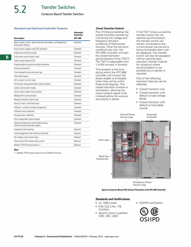
Closed Transition ControlsThe CTC9 accomplishes the closed transition transfer by monitoring the voltage and frequency set point conditions of both power sources. Once the set point conditions are met, the ATC-900 controller will start the closed transition synchronization timer (TSCT). The TSCT is adjustable from 1 to 60 minutes in duration.
This duration is the time during which the ATC-900 controller will monitor the phase angles to anticipate when they will be within 8 electrical degrees. The closed transition scheme is anticipatory, allowing the close contacts signal to be initiated before the sources are exactly in phase.
If the TSCT times out and the transfer switch has not reached synchronization, the transfer switch will remain connected to the current power source and a failure-to-transfer alarm will be displayed. The transfer switch can also be equipped with an optional open transition transfer method for situations where synchronization is not possible but a transfer is required.
One of the following transition features can be selected:
● Closed transition only● Closed transition with
default to load voltage decay
● Closed transition with default to time delay neutral
Typical Contactor-Based ATS (Closed Transition) with ATC-900 Controller
Standards and Certifications● UL 1008 Listed● CSA C22.2 No. 178
Certified● Seismic Zone 4 qualified
(CBC, IBC, UBC)
● OSHPD certification
Automatic
Controller
Normal Power
Source Lugs
Emergency Power
Source Lugs
Load Lugs
Multi-Tap
Transformer

Volume 2—Commercial Distribution CA08100003E—February 2018 www.eaton.com V2-T5-23
5
5
5
5
5
5
5
5
5
5
5
5
5
5
5
5
5
5
5
5
5
5
5
5
5
5
5
5
5
5
5.2Transfer Switches
Contactor-Based Transfer Switches
Catalog Number Selection
Contactor-Based Automatic Transfer Switch (Closed Transition)
Technical Data and Specifications
UL 1008 Transfer Switch (Contactor-Based) Short-Circuit Withstand and Closing Current Ratings
Notes1 For open transition transfer switches rated 40–200 A (C2 switching mechanism) time duration is 0.025 sec maximum.2 For closed transition transfer switches rated 40–200 A (C3 switching mechanism) time duration is 0.025 sec maximum.3 For closed transition transfer switches rated 40–100 A (C3 switching mechanism) or 150–200 A (C3 switching mechanism),
the short-circuit withstand closing current ratings associated with a C2 switching mechanism apply.
Transfer Switch Rating (A)
Switching Mechanism (Device Type)
Short-Circuit Withstand Closing Current Rating (kA)When Protected by aCircuit Breaker
When Protected by aSpecific Circuit Breaker When Protected by a Specific Fuse
Time Duration (0.05 sec.1 2 Max.) Mfg. and Type Based Mfg. and Type BasedMax. Fuse Size (A)
600 Vac Max. (kA)
FuseClass
Max. Fuse Size (A)
480 Vac Max. (kA)
600 Vac Max. (kA)
480 Vac Max. (kA)
600 Vac Max. (kA)
480 Vac Max. (kA)
FuseClass
40, 80, 100 C2 10 10 30 22 100 K5, RK5 200 100 K5, RK5 200
K1, RK1 400 K1, RK1 400
J, T 450 J, T 450
150, 200 C2 10 22 30 35 100 K5, RK5 400 200 RK1, RK5, J, C, K1, K5
600
J, K1, RK1 600 L 800
T 800 T 1200
225, 260, 400 C2 30 — 50 — 200 RK1, RK5, J, C, K1, K5
600 200 J, T, L, RK5 600
L 800 L 1600
T 1200
40 3, 80 3, 100 3, 150 3, 200 3
C3 3, C5 30 3 22 3 50 3 35 3 200 3 RK1, RK5, J, C, K1, K5
600 200 3 RK1, RK5, J, C, K1, K5
600
L 800 L 800
T 1200 T 1200
225, 260, 400 C3, C5 30 50 50 65 200 RK1, RK5, J, C, K1, K5
600 200 J, T, L, RK5 600
L 800 L 1600
T 1200
600, 800, 1000, 1200
C3, C5 50 50 65 65 200 J, T, L, RK5 600 200 J, T, L, RK5 600
L 1600 L 1600
1600 C3, C5 50 — 65 — 200 J, T, L, RK5 600 — — —
L 2000 — —
TypeCT = Closed transition
OrientationC = Contactor
Logic9 = ATC-900
MechanismC3 = 3-position
MountingX = Fix mount
Amperes0040 = 40 A0080 = 80 A0100 = 100 A0150 = 150 A0200 = 200 A0225 = 225 A0260 = 260 A0400 = 400 A0600 = 600 A0800 = 800 A1000 = 1000 A1200 = 1200 A
VoltageA = 120 V, 60 HzB = 208 V, 60 HzE = 600 V, 60 HzG = 220 V, 50 HzH = 380 V, 50 HzW = 240 V, 60 HzX = 480 V, 60 Hz
EnclosureK = OpenS = NEMA 1J = NEMA 12R = NEMA 3R
CertificationU = UL listed
Number ofPoles
3 = Three-pole4 = Four-pole
CT C 9 C3 X 3 0400 X S U
V2-T5-24 Volume 2—Commercial Distribution CA08100003E—February 2018 www.eaton.com
5
5
5
5
5
5
5
5
5
5
5
5
5
5
5
5
5
5
5
5
5
5
5
5
5
5
5
5
5
5
5.2 Transfer Switches
Contactor-Based Transfer Switches
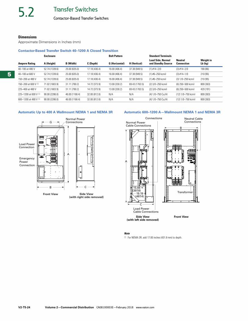
DimensionsApproximate Dimensions in Inches (mm)
Contactor-Based Transfer Switch 40–1200 A Closed Transition
Automatic Up to 400 A Wallmount NEMA 1 and NEMA 3R Automatic 600–1200 A—Wallmount NEMA 1 and NEMA 3R
Note1 For NEMA 3R, add 17.00 inches (431.8 mm) to depth.
Ampere Rating
Enclosure Bolt Pattern Standard Terminals
A (Height) B (Width) C (Depth) G (Horizontal) H (Vertical)Load Side, Normal and Standby Source
NeutralConnection
Weight in Lb (kg)
40–100 at 480 V 52.74 (1339.6) 25.00 (635.0) 17.18 (436.4) 16.00 (406.4) 37.38 (949.5) (1) #14–2/0 (3) #14–2/0 190 (86)
40–100 at 600 V 52.74 (1339.6) 25.00 (635.0) 17.18 (436.4) 16.00 (406.4) 37.38 (949.5) (1) #6–250 kcmil (3) #14–1/0 210 (95)
150–200 at 480 V 52.74 (1339.6) 25.00 (635.0) 17.18 (436.4) 16.00 (406.4) 37.38 (949.5) (1) #6–250 kcmil (3) 1/0–250 kcmil 210 (95)
150–200 at 600 V 1 71.02 (1803.9) 31.11 (790.2) 14.72 (373.9) 13.00 (330.2) 69.43 (1763.5) (2) 3/0–250 kcmil (6) 250–500 kcmil 800 (363)
225–400 at 480 V 71.02 (1803.9) 31.11 (790.2) 14.72 (373.9) 13.00 (330.2) 69.43 (1763.5) (2) 3/0–250 kcmil (6) 250–500 kcmil 420 (191)
225–1200 at 600 V 1 90.00 (2286.0) 46.00 (1168.4) 32.00 (812.8) N/A N/A (4) 1/0–750 Cu/Al (12) 1/0–750 kcmil 800 (363)
600–1200 at 480 V 1 90.00 (2286.0) 46.00 (1168.4) 32.00 (812.8) N/A N/A (4) 1/0–750 Cu/Al (12) 1/0–750 kcmil 800 (363)
G
A
B C
Emergency
Power
Connection
Normal Power Connections
Load PowerConnection
Front View Side View(with right side removed)
C
A
Front ViewSide View(with left side removed)
15.66(397.8)
19.19(487.4)
Load PowerCable Connections
Connections
Normal Power Cable Connections
Neutral Cable Connections
B
Transformer
Volume 2—Commercial Distribution CA08100003E—February 2018 www.eaton.com V2-T5-25
5
5
5
5
5
5
5
5
5
5
5
5
5
5
5
5
5
5
5
5
5
5
5
5
5
5
5
5
5
5
5.2Transfer Switches
Contactor-Based Transfer Switches
Contactor-Based Transfer Switch ContentsDescription Page
Contactor-Based Transfer SwitchOpen Transition, 40–1600 A . . . . . . . . . . . . . . . . V2-T5-8
Service Entrance Rated—Contactor-Based Transfer SwitchOpen Transition, Service Entrance
Rated, 40–1600 A . . . . . . . . . . . . . . . . . . . . . . V2-T5-14
Contactor-Based Automatic Transfer SwitchClosed Transition, 40–1200 A . . . . . . . . . . . . . . . V2-T5-21
Contactor-Based Transfer SwitchOpen and Closed Transition, 1600–3000 A
Features and Benefits . . . . . . . . . . . . . . . . . V2-T5-26
Standards and Certifications . . . . . . . . . . . . V2-T5-27
Catalog Number Selection . . . . . . . . . . . . . V2-T5-27
Technical Data and Specifications . . . . . . . . V2-T5-28
Dimensions . . . . . . . . . . . . . . . . . . . . . . . . . V2-T5-28
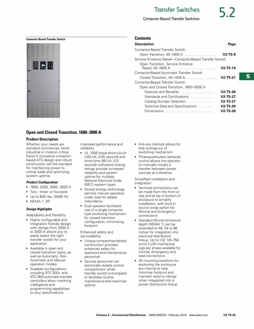
Open and Closed Transition, 1600–3000 AProduct DescriptionWhether your needs are standard commercial, harsh industrial or mission critical, Eaton’s innovative contactor-based ATS design and robust construction set the standard for maintaining power to critical loads and optimizing system uptime.
Product Configuration● 1600, 2000, 2600, 3000 A● Two-, three- or four-pole● Up to 600 Vac, 50/60 Hz● NEMA 1, 3R
Design Highlights
Adaptability and flexibility● Highly configurable and
integration friendly design with ratings from 2000 A to 3000 A allows you to easily select the right transfer switch for your application
● Available in open and closed transition types, as well as Automatic, Non-Automatic and Manual operation modes
● Scalable configurations including ATC-300+ and ATC-900 automatic transfer controllers allow matching intelligence and programming capabilities to your specifications
Improved performance and reliability● UL 1008 listed short-circuit
(100 kA; 0.05 second) and short-time (85 kA; 0.5 second) withstand closing ratings provide increased reliability and system uptime for multiple National Electrical Code (NEC) system types
● Stored energy technology permits manual operation under load for added redundancy
● Dual operator facilitates use of a single contactor type switching mechanism for closed transition configuration, minimizing footprint
Enhanced safety and serviceability● Unique compartmentalized
construction provides enhanced safety for operators and maintenance personnel
● Service personnel can electrically isolate control compartment while transfer switch is energized to facilitate routine maintenance and maximize uptime
● Kirk-key interlock allows for lock-out/tag-out of switching mechanism
● Three-pushbutton tethered control allows the operator to manually initiate a transfer between power sources at a distance
Simplified installation and integration● Terminal connections can
be made from the front or rear and at top or bottom of enclosure to simplify installation, with built-in source swap option for Normal and Emergency connections
● Standard 40-inch enclosure depth (NEMA 1) can be extended to 48, 54 or 66 inches for integration into electrical distribution lineup. Up to (12) 1/0–750 kcmil Cu/Al mechanical lugs per phase available for normal, emergency and load connections
● All mounting locations for anchoring the enclosure are internal to help minimize footprint and maintain seismic ratings when integrated into a power distribution lineup
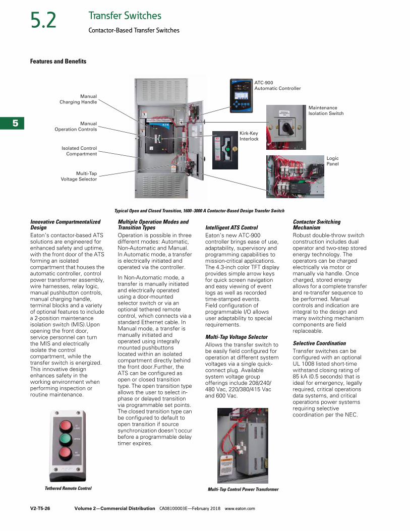
V2-T5-26 Volume 2—Commercial Distribution CA08100003E—February 2018 www.eaton.com
5
5
5
5
5
5
5
5
5
5
5
5
5
5
5
5
5
5
5
5
5
5
5
5
5
5
5
5
5
5
5.2 Transfer Switches
Contactor-Based Transfer Switches
Features and Benefits
Typical Open and Closed Transition, 1600–3000 A Contactor-Based Design Transfer Switch
Innovative Compartmentalized DesignEaton’s contactor-based ATS solutions are engineered for enhanced safety and uptime, with the front door of the ATS forming an isolated compartment that houses the automatic controller, control power transformer assembly, wire harnesses, relay logic, manual pushbutton controls, manual charging handle, terminal blocks and a variety of optional features to include a 2-position maintenance isolation switch (MIS).Upon opening the front door, service personnel can turn the MIS and electrically isolate the control compartment, while the transfer switch is energized. This innovative design enhances safety in the working environment when performing inspection or routine maintenance.
Tethered Remote Control
Multiple Operation Modes and Transition TypesOperation is possible in three different modes: Automatic, Non-Automatic and Manual. In Automatic mode, a transfer is electrically initiated and operated via the controller.
In Non-Automatic mode, a transfer is manually initiated and electrically operated using a door-mounted selector switch or via an optional tethered remote control, which connects via a standard Ethernet cable. In Manual mode, a transfer is manually initiated and operated using integrally mounted pushbuttons located within an isolated compartment directly behind the front door.Further, the ATS can be configured as open or closed transition type. The open transition type allows the user to select in-phase or delayed transition via programmable set points. The closed transition type can be configured to default to open transition if source synchronization doesn’t occur before a programmable delay timer expires.
Intelligent ATS ControlEaton’s new ATC-900 controller brings ease of use, adaptability, supervisory and programming capabilities to mission-critical applications. The 4.3-inch color TFT display provides simple arrow keys for quick screen navigation and easy viewing of event logs as well as recorded time-stamped events. Field configuration of programmable I/O allows user adaptability to special requirements.
Multi-Tap Voltage SelectorAllows the transfer switch to be easily field configured for operation at different system voltages via a single quick-connect plug. Available system voltage group offerings include 208/240/ 480 Vac, 220/380/415 Vac and 600 Vac.
Multi-Tap Control Power Transformer
Contactor Switching MechanismRobust double-throw switch construction includes dual operator and two-step stored energy technology. The operators can be charged electrically via motor or manually via handle. Once charged, stored energy allows for a complete transfer and re-transfer sequence to be performed. Manual controls and indication are integral to the design and many switching mechanism components are field replaceable.
Selective CoordinationTransfer switches can be configured with an optional UL 1008 listed short-time withstand closing rating of 85 kA (0.5 seconds) that is ideal for emergency, legally required, critical operations data systems, and critical operations power systems requiring selective coordination per the NEC.
Manual
Charging Handle
Maintenance
Isolation Switch
Kirk-Key
Interlock
ATC-900
Automatic Controller
Logic
Panel
Manual
Operation Controls
Isolated Control
Compartment
Multi-Tap
Voltage Selector
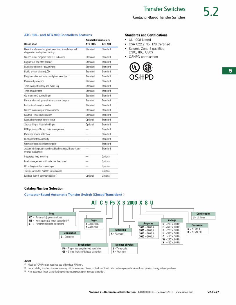
Volume 2—Commercial Distribution CA08100003E—February 2018 www.eaton.com V2-T5-27
5
5
5
5
5
5
5
5
5
5
5
5
5
5
5
5
5
5
5
5
5
5
5
5
5
5
5
5
5
5
5.2Transfer Switches
Contactor-Based Transfer Switches
ATC-300+ and ATC-900 Controllers Features Standards and Certifications● UL 1008 Listed● CSA C22.2 No. 178 Certified● Seismic Zone 4 qualified
(CBC, IBC, UBC)● OSHPD certification
Catalog Number Selection
Contactor-Based Automatic Transfer Switch (Closed Transition) 2
Notes1 Modbus TCP/IP option requires use of Modbus RTU port.2 Some catalog number combinations may not be available. Please contact your local Eaton sales representative with any product configuration questions.3 Non-automatic (open transition) type does not support open-inphase transition.
Automatic ControllersDescription ATC-300+ ATC-900
Basic transfer control, plant exerciser, time delays, self diagnostics and system settings
Standard Standard
Source mimic diagram with LED indication Standard Standard
Engine test and start contact Standard Standard
Dual source control power input Standard Standard
Liquid crystal display (LCD) Standard Standard
Programmable set points and plant exerciser Standard Standard
Password protection Standard Standard
Time stamped history and event log Standard Standard
Time delay bypass Standard Standard
Go to source 2 control input Standard Standard
Pre-transfer and general alarm control outputs Standard Standard
Lockout and monitor modes Standard Standard
Source status output relay contacts Standard Standard
Modbus RTU communication Standard Standard
Manual retransfer control input Optional Standard
Source 2 input / load shed input Optional Standard
USB port—profile and data management — Standard
Preferred source selection — Standard
Dual generator capability — Standard
User configurable inputs/outputs — Standard
Advanced diagnostics and troubleshooting with pre-/post-event data capture
— Standard
Integrated load metering — Optional
Load management with selective load shed — Optional
DC voltage control power input — Optional
Three source ATS master/slave control — Optional
Modbus TCP/IP communication 1 Optional Optional
TypeAT = Automatic (open transition)NT = Non-automatic (open transition) 3CT = Automatic (closed transition)
OrientationC = Contactor
Logic3 = ATC-300+9 = ATC-900
MechanismF5 = F type, inphase/delayed transitionG5 = G type, inphase/delayed transition
MountingX = Fix mount
Amperes1600 = 1600 A2000 = 2000 A2600 = 2600 A3000 = 3000 A
VoltageB = 208 V, 60 HzE = 600 V, 60 HzG = 220 V, 50 HzH = 380 V, 50 HzO = 415 V, 50 HzW = 240 V, 60 HzX = 480 V, 60 Hz
EnclosureS = NEMA 1R = NEMA 3R
CertificationU = UL listed
AT C 9 F5 X 3 2000 X S U
Number of Poles3 = Three-pole4 = Four-pole
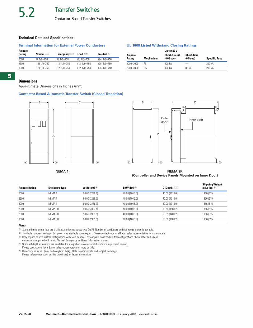
V2-T5-28 Volume 2—Commercial Distribution CA08100003E—February 2018 www.eaton.com
5
5
5
5
5
5
5
5
5
5
5
5
5
5
5
5
5
5
5
5
5
5
5
5
5
5
5
5
5
5
5.2 Transfer Switches
Contactor-Based Transfer Switches
Technical Data and Specifications
Terminal Information for External Power Conductors UL 1008 Listed Withstand Closing Ratings
DimensionsApproximate Dimensions in Inches (mm)
Contactor-Based Automatic Transfer Switch (Closed Transition)
Notes1 Standard mechanical lugs are UL listed, solderless screw-type Cu/Al. Number of conductors and size range shown is per pole.2 Two-hole compression lug or bus provisions available upon request. Please contact your local Eaton sales representative for more details.3 Only applies to wye system configuration with solid neutral. For four-pole, switched neutral configurations, the number and size of
conductors supported will mimic Normal, Emergency and Load information shown.4 Standard depth extensions are available for integration into electrical distribution equipment line-up.
Please contact your local Eaton sales representative for more details.5 Dimension in inches (mm) and weight in lb (kg). Data is approximate and subject to change.
Please reference product outline drawing(s) for latest information.
Ampere Rating Normal 12 Emergency 12 Load 12 Neutral 3
2000 (8) 1/0–750 (8) 1/0–750 (8) 1/0–750 (24) 1/0–750
2600 (12) 1/0–750 (12) 1/0–750 (12) 1/0–750 (36) 1/0–750
3000 (12) 1/0–750 (12) 1/0–750 (12) 1/0–750 (36) 1/0–750
Up to 600 VAmpereRating Mechanism
Short-Circuit (0.05 sec)
Short-Time (0.5 sec) Specific Fuse
2000–3000 F5 100 kA — 200 kA
2000–3000 G5 100 kA 85 kA 200 kA
Ampere Rating Enclosure Type A (Height) 5 B (Width) 5 C (Depth) 45Shipping Weight in Lb (kg) 5
2000 NEMA 1 90.00 (2286.0) 40.00 (1016.0) 40.00 (1016.0) 1356 (615)
2600 NEMA 1 90.00 (2286.0) 40.00 (1016.0) 40.00 (1016.0) 1356 (615)
3000 NEMA 1 90.00 (2286.0) 40.00 (1016.0) 40.00 (1016.0) 1356 (615)
2000 NEMA 3R 90.69 (2303.5) 40.00 (1016.0) 58.59 (1488.2) 1356 (615)
2600 NEMA 3R 90.69 (2303.5) 40.00 (1016.0) 58.59 (1488.2) 1356 (615)
3000 NEMA 3R 90.69 (2303.5) 40.00 (1016.0) 58.59 (1488.2) 1356 (615)
NEMA 1 NEMA 3R
(Controller and Device Panels Mounted on Inner Door)
A
B C
A
B C
Outer
doorInner door

Volume 2—Commercial Distribution CA08100003E—February 2018 www.eaton.com V2-T5-29
5
5
5
5
5
5
5
5
5
5
5
5
5
5
5
5
5
5
5
5
5
5
5
5
5
5
5
5
5
5
5.3Transfer Switches
Bypass Isolation Contactor-Based Transfer Switches
Bypass Isolation Contactor-Based Transfer Switch ContentsDescription Page
Bypass Isolation Contactor-Based Transfer SwitchesOpen and Closed Transition,
Dual Drawout, 40–1600 AFeatures, Benefits and Functions . . . . . . . . V2-T5-30
Standards and Certifications . . . . . . . . . . . . V2-T5-32
Catalog Number Selection . . . . . . . . . . . . . V2-T5-32
Technical Data and Specifications . . . . . . . . V2-T5-32
Diagrams . . . . . . . . . . . . . . . . . . . . . . . . . . . V2-T5-33
Dimensions . . . . . . . . . . . . . . . . . . . . . . . . . V2-T5-34
Open and Closed Transition, Drawout ATS, Fixed Bypass, 40–1200 A . . . . . . . . . . . . . . . . . V2-T5-35
Open and Closed Transition, Dual Drawout, 40–1600 AProduct DescriptionEaton’s bypass isolation transfer switch is used in life safety and other mission- critical applications where redundancy is desired and maintenance of the automatic transfer switch can be performed without interrupting power to the load. Transfer switches can be equipped with the ATC-300+ or ATC-900 controller.
Product Configuration● 100, 150, 200, 225, 260,
400, 600, 800, 1000, 1200 and 1600 A
● Two-, three- or four-pole (fourth pole is fully rated)
● Up to 600 Vac, 50/60 Hz● NEMA 1, 3R, 12, 4X
Design Highlights● Front access is a standard
feature on all ratings● Entry:
● Top, bottom or both● Isolated compartments
● Improved safety:● Isolated compartments
with barriers● Single motion rack-out
with doors closed● Ability to test power
switching elements during drawout process
● Dual ATS capability—both the ATS switch and bypass switch operate in automatic mode
● Installation flexibility:● Field entry/exit locations
can be modified in the field
● Interchangeable drawout contactors
● Field-selectable multi-tap transformer panel permits operation on a wide range of system voltages
● Dual drawout—ATS and bypass
V2-T5-30 Volume 2—Commercial Distribution CA08100003E—February 2018 www.eaton.com
5
5
5
5
5
5
5
5
5
5
5
5
5
5
5
5
5
5
5
5
5
5
5
5
5
5
5
5
5
5
5.3 Transfer Switches
Bypass Isolation Contactor-Based Transfer Switches
Features, Benefits and Functions
Standard Features● Drawout cassette design
on both ATS and bypass● No service interruption in
bypass to the same source● Source available contacts:
● Source 1 present 2NO and 2NC
● Source 2 present 2NO and 2NC
● Switch position contacts:● Source 1 position
1NO and 1NC● Source 2 position
1NO and 1NC● Source 1 and Source 2
sensing:● Undervoltage/
underfrequency● Overvoltage/
overfrequency● Three-phase rotation
protection (ATC-300+ only)
● Three-phase voltage unbalance/loss (ATC-300+ only)
● Pretransfer signal contacts 1NO and 1NC (open transition only)
● Go to Source 2 (EMERGENCY)
● Field-programmable time delays:● Time delay engine start:
0–1200 seconds● Time delay normal
to emergency: 0–1800 seconds
● Time delay emergency to normal: 0–1800 seconds
● Time delay engine cooldown: 0–1800 seconds
● Time delay emergency failure: 0–6 seconds
● LCD-based display for programming, system diagnostics and Help menu display
● Mimic diagram with source available and connected LED indication
● Time-stamped history log● System TEST pushbutton● Programmable plant
exerciser—OFF, daily, 7-, 14-, 28-day interval selectable run time 0–600 minutes no load/load with fail-safe
Optional Features● Surge protection
(UL 1449 3rd Edition)● Eaton IQ and Power Xpert
multi-function power quality metering
● Automatic transfer mode with selectable non-automatic/automatic retransfer mode
● Modbus RTU via RS-485● Remote annunciation with
control● Open in-phase transition,
time delay neutral or in-phase with a default to time delay neutral transfer
● ATC-900 controller● Includes Modbus RTU
via RS-485● Includes four
programmable inputs/outputs
● Includes two plant exercisers
● Includes LCD color display with easy navigation tools to settings and event logs
● Expandable I/O (up to 20 I/O total)
● Optional integrated load metering
● Optional EtherNet TCP/IP communications
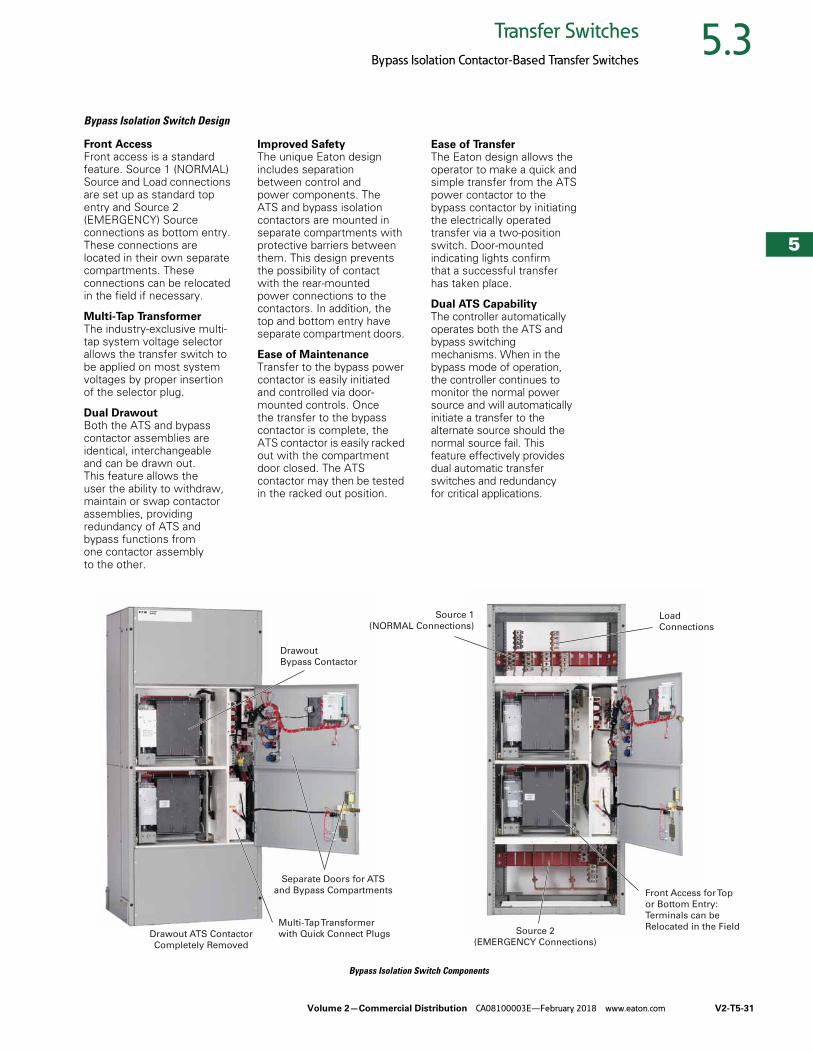
Volume 2—Commercial Distribution CA08100003E—February 2018 www.eaton.com V2-T5-31
5
5
5
5
5
5
5
5
5
5
5
5
5
5
5
5
5
5
5
5
5
5
5
5
5
5
5
5
5
5
5.3Transfer Switches
Bypass Isolation Contactor-Based Transfer Switches
Bypass Isolation Switch Design
Front AccessFront access is a standard feature. Source 1 (NORMAL) Source and Load connections are set up as standard top entry and Source 2 (EMERGENCY) Source connections as bottom entry. These connections are located in their own separate compartments. These connections can be relocated in the field if necessary.
Multi-Tap Transformer The industry-exclusive multi-tap system voltage selector allows the transfer switch to be applied on most system voltages by proper insertion of the selector plug.
Dual Drawout Both the ATS and bypass contactor assemblies are identical, interchangeable and can be drawn out. This feature allows the user the ability to withdraw, maintain or swap contactor assemblies, providing redundancy of ATS and bypass functions from one contactor assembly to the other.
Improved SafetyThe unique Eaton design includes separation between control and power components. The ATS and bypass isolation contactors are mounted in separate compartments with protective barriers between them. This design prevents the possibility of contact with the rear-mounted power connections to the contactors. In addition, the top and bottom entry have separate compartment doors.
Ease of MaintenanceTransfer to the bypass power contactor is easily initiated and controlled via door-mounted controls. Once the transfer to the bypass contactor is complete, the ATS contactor is easily racked out with the compartment door closed. The ATS contactor may then be tested in the racked out position.
Ease of TransferThe Eaton design allows the operator to make a quick and simple transfer from the ATS power contactor to the bypass contactor by initiating the electrically operated transfer via a two-position switch. Door-mounted indicating lights confirm that a successful transfer has taken place.
Dual ATS CapabilityThe controller automatically operates both the ATS and bypass switching mechanisms. When in the bypass mode of operation, the controller continues to monitor the normal power source and will automatically initiate a transfer to the alternate source should the normal source fail. This feature effectively provides dual automatic transfer switches and redundancy for critical applications.
Bypass Isolation Switch Components
Source 1
(NORMAL Connections)Load
Connections
Source 2
(EMERGENCY Connections)
Front Access for Top
or Bottom Entry:
Terminals can be
Relocated in the Field
Drawout
Bypass Contactor
Separate Doors for ATS
and Bypass Compartments
Multi-Tap Transformer
with Quick Connect PlugsDrawout ATS Contactor
Completely Removed
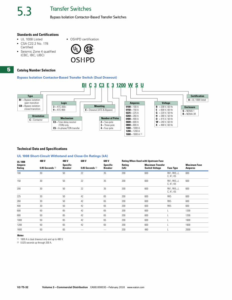
V2-T5-32 Volume 2—Commercial Distribution CA08100003E—February 2018 www.eaton.com
5
5
5
5
5
5
5
5
5
5
5
5
5
5
5
5
5
5
5
5
5
5
5
5
5
5
5
5
5
5
5.3 Transfer Switches
Bypass Isolation Contactor-Based Transfer Switches
Standards and Certifications● UL 1008 Listed● CSA C22.2 No. 178
Certified● Seismic Zone 4 qualified
(CBC, IBC, UBC)
● OSHPD certification
Catalog Number Selection
Bypass Isolation Contactor-Based Transfer Switch (Dual Drawout)
Technical Data and Specifications
UL 1008 Short-Circuit Withstand and Close-On Ratings (kA)
Notes1 1600 A is dual drawout only and up to 480 V.2 0.025 seconds up through 200 A.
UL 1008Ampere Rating
480 V 480 V 600 V 600 V Rating When Used with Upstream Fuse
0.05 Seconds 2Specific Breaker 0.05 Seconds 2
Specific Breaker
Rating (kA)
Maximum Transfer Switch Voltage Fuse Type
Maximum Fuse Amperes
100 30 50 22 35 200 600 RK1, RK5, J, C, K1, K5
600
150 30 50 22 35 200 600 RK1, RK5, J, C, K1, K5
600
200 30 50 22 35 200 600 RK1, RK5, J, C, K1, K5
600
225 30 50 42 65 200 600 RK5 600
260 30 50 42 65 200 600 RK5 600
400 30 50 42 65 200 600 RK5 600
600 50 65 42 65 200 600 L 1200
800 50 65 42 65 200 600 L 1200
1000 50 65 42 65 200 600 L 1600
1200 50 65 42 65 200 600 L 1600
1600 50 65 — — 200 480 L 2000
BI C 3 C3 E 3 1200 W S U
Amperes0100 = 100 A0150 = 150 A0225 = 225 A0260 = 260 A0400 = 400 A0600 = 600 A0800 = 800 A1000 = 1000 A1200 = 1200 A1600 = 1600 A 1
VoltageB = 208 V, 60 HzE = 600 V, 60 HzG = 220 V, 50 HzH = 380 V, 50 HzO = 415 V, 50 HzW = 240 V, 60 HzX = 480 V, 60 Hz
CertificationU = UL 1008 listed
EnclosureS = NEMA 1R = NEMA 3R
MountingE = Drawout (ATS & Bypass)
Number of Poles2 = Two-pole3 = Three-pole4 = Four-pole
Logic3 = ATC-300+9 = ATC-900
TypeBI = Bypass isolation
open transitionCB = Bypass isolation
closed transition
OrientationC = Contactor Mechanism
C3 = Time delay neutral(TDN) only
C5 = In-phase/TDN transfer
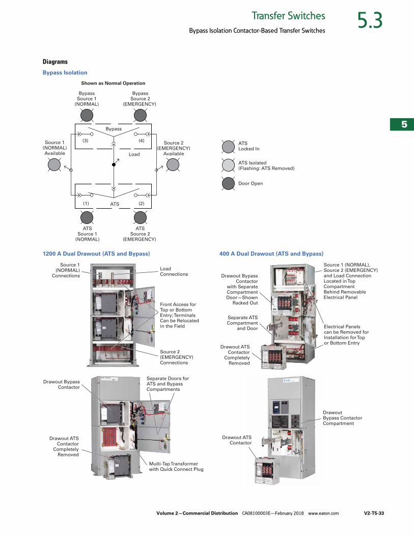
Volume 2—Commercial Distribution CA08100003E—February 2018 www.eaton.com V2-T5-33
5
5
5
5
5
5
5
5
5
5
5
5
5
5
5
5
5
5
5
5
5
5
5
5
5
5
5
5
5
5
5.3Transfer Switches
Bypass Isolation Contactor-Based Transfer Switches
Diagrams
Bypass Isolation
1200 A Dual Drawout (ATS and Bypass) 400 A Dual Drawout (ATS and Bypass)
Load
Bypass
ATS
(3) (4)
(1) (2)
Source 1(NORMAL)Available
Shown as Normal Operation
Source 2(EMERGENCY)
Available
BypassSource 1
(NORMAL)
ATSSource 1
(NORMAL)
ATSSource 2
(EMERGENCY)
BypassSource 2
(EMERGENCY)
ATSLocked In
Door Open
ATS Isolated(Flashing: ATS Removed)
Source 1 (NORMAL)
Connections
Load Connections
Source 2 (EMERGENCY) Connections
Front Access for Top or Bottom Entry; Terminals Can be Relocated in the Field
Separate Doors for ATS and Bypass Compartments
Drawout BypassContactor
Multi-Tap Transformer with Quick Connect Plug
Drawout ATSContactor
Completely Removed
Source 1 (NORMAL),Source 2 (EMERGENCY)and Load ConnectionLocated in TopCompartmentBehind Removable Electrical Panel
Electrical Panels can be Removed for Installation for Top or Bottom Entry
Drawout ATS Contactor
Completely Removed
Separate ATS Compartment
and Door
Drawout Bypass Contactor
with SeparateCompartment Door—Shown
Racked Out
Drawout Bypass Contactor Compartment
Drawout ATS Contactor
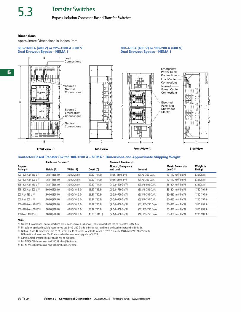
V2-T5-34 Volume 2—Commercial Distribution CA08100003E—February 2018 www.eaton.com
5
5
5
5
5
5
5
5
5
5
5
5
5
5
5
5
5
5
5
5
5
5
5
5
5
5
5
5
5
5
5.3 Transfer Switches
Bypass Isolation Contactor-Based Transfer Switches
DimensionsApproximate Dimensions in Inches (mm)
600–1600 A (480 V) or 225–1200 A (600 V)Dual Drawout Bypass—NEMA 1
100–400 A (480 V) or 100–200 A (600 V) Dual Drawout Bypass—NEMA 1
Contactor-Based Transfer Switch 100–1200 A—NEMA 1 Dimensions and Approximate Shipping Weight
Notes1 Source 1 Normal and Load connections are top and Source 2 is bottom. These connections can be relocated in the field.2 For seismic applications, it is necessary to use 5–13 UNC Grade or better hex head bolts and washers torqued to 50 ft-lbs.3 NEMA 12 and 4X dimensions are 90.00 inches H x 46.00 inches W x 38.00 inches D (2286.0 mm H x 1168.4 mm W x 965.2 mm D).
NEMA 4X enclosures are 304SS standard with an optional upgrade to 316SS.4 Same number of terminals per phase will be supplied.5 For NEMA 3R dimensions, add 18.29 inches (464.6 mm).6 For NEMA 3R dimensions, add 18.59 inches (472.2 mm).
LoadConnections
Source 1NormalConnections
Source 2EmergencyConnections
NeutralConnections
Bypass
ATS
CG
Front View Side View
B
B
A
C
Front View Side View
Emergency Power Cable Connections
Load CableConnections
Normal Power Cable Connections
Electrical Panel Not Shown forClarity
A
B C
AmpereRating 3
Enclosure Seismic 2 Standard Terminals 4
Weight in Lb (kg) Height (A) Width (B) Depth (C)
Normal, Emergencyand Load Neutral
Metric Conversion(mm2) 4
100–200 A at 480 V 5 78.07 (1983.0) 30.00 (762.0) 29.30 (744.2) (1) #6–350 Cu/Al (3) #6–350 Cu/Al 13–177 mm2 Cu/Al 625 (283.8)
100–200 A at 600 V 5 78.07 (1983.0) 30.00 (762.0) 29.30 (744.2) (1) #6–350 Cu/Al (3) #6–350 Cu/Al 13–177 mm2 Cu/Al 625 (283.8)
225–400 A at 480 V 5 78.07 (1983.0) 30.00 (762.0) 29.30 (744.2) (1) 3/0–600 Cu/Al (3) 3/0–600 Cu/Al 85–304 mm2 Cu/Al 625 (283.8)
225–400 A at 600 V 6 90.00 (2286.0) 40.00 (1016.0) 28.97 (735.8) (2) 3/0–750 Cu/Al (6) 3/0–750 Cu/Al 85–304 mm2 Cu/Al 1750 (794.5)
600 A at 480 V 6 90.00 (2286.0) 40.00 (1016.0) 28.97 (735.8) (2) 3/0–750 Cu/Al (6) 3/0–750 Cu/Al 85–380 mm2 Cu/Al 1750 (794.5)
600 A at 600 V 6 90.00 (2286.0) 40.00 (1016.0) 28.97 (735.8) (2) 3/0–750 Cu/Al (6) 3/0–750 Cu/Al 85–380 mm2 Cu/Al 1750 (794.5)
800–1200 A at 480 V 6 90.00 (2286.0) 40.00 (1016.0) 28.97 (735.8) (4) 3/0–750 Cu/Al (12) 3/0–750 Cu/Al 85–380 mm2 Cu/Al 1850 (839.9)
800–1200 A at 600 V 6 90.00 (2286.0) 40.00 (1016.0) 28.97 (735.8) (4) 3/0–750 Cu/Al (12) 3/0–750 Cu/Al 85–380 mm2 Cu/Al 1850 (839.9)
1600 A at 480 V 6 90.00 (2286.0) 40.00 (1016.0) 40.00 (1016.0) (5) 1/0–750 Cu/Al (16) 1/0–750 Cu/Al 85–380 mm2 Cu/Al 2200 (997.9)
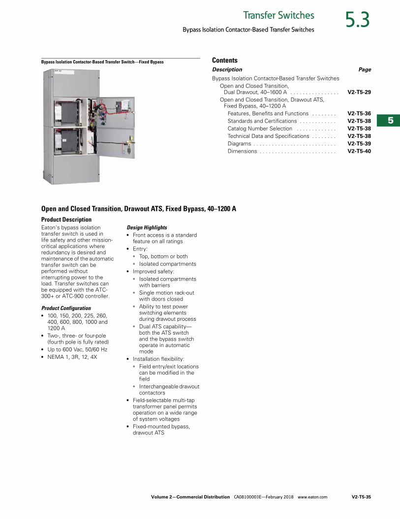
Volume 2—Commercial Distribution CA08100003E—February 2018 www.eaton.com V2-T5-35
5
5
5
5
5
5
5
5
5
5
5
5
5
5
5
5
5
5
5
5
5
5
5
5
5
5
5
5
5
5
5.3Transfer Switches
Bypass Isolation Contactor-Based Transfer Switches
Bypass Isolation Contactor-Based Transfer Switch—Fixed Bypass ContentsDescription Page
Bypass Isolation Contactor-Based Transfer SwitchesOpen and Closed Transition,
Dual Drawout, 40–1600 A . . . . . . . . . . . . . . . . V2-T5-29
Open and Closed Transition, Drawout ATS, Fixed Bypass, 40–1200 A
Features, Benefits and Functions . . . . . . . . V2-T5-36
Standards and Certifications . . . . . . . . . . . . V2-T5-38
Catalog Number Selection . . . . . . . . . . . . . V2-T5-38
Technical Data and Specifications . . . . . . . . V2-T5-38
Diagrams . . . . . . . . . . . . . . . . . . . . . . . . . . . V2-T5-39
Dimensions . . . . . . . . . . . . . . . . . . . . . . . . . V2-T5-40
Open and Closed Transition, Drawout ATS, Fixed Bypass, 40–1200 AProduct DescriptionEaton’s bypass isolation transfer switch is used in life safety and other mission- critical applications where redundancy is desired and maintenance of the automatic transfer switch can be performed without interrupting power to the load. Transfer switches can be equipped with the ATC-300+ or ATC-900 controller.
Product Configuration● 100, 150, 200, 225, 260,
400, 600, 800, 1000 and 1200 A
● Two-, three- or four-pole (fourth pole is fully rated)
● Up to 600 Vac, 50/60 Hz● NEMA 1, 3R, 12, 4X
Design Highlights● Front access is a standard
feature on all ratings● Entry:
● Top, bottom or both● Isolated compartments
● Improved safety:● Isolated compartments
with barriers● Single motion rack-out
with doors closed● Ability to test power
switching elements during drawout process
● Dual ATS capability—both the ATS switch and the bypass switch operate in automatic mode
● Installation flexibility:● Field entry/exit locations
can be modified in the field
● Interchangeable drawout contactors
● Field-selectable multi-tap transformer panel permits operation on a wide range of system voltages
● Fixed-mounted bypass, drawout ATS
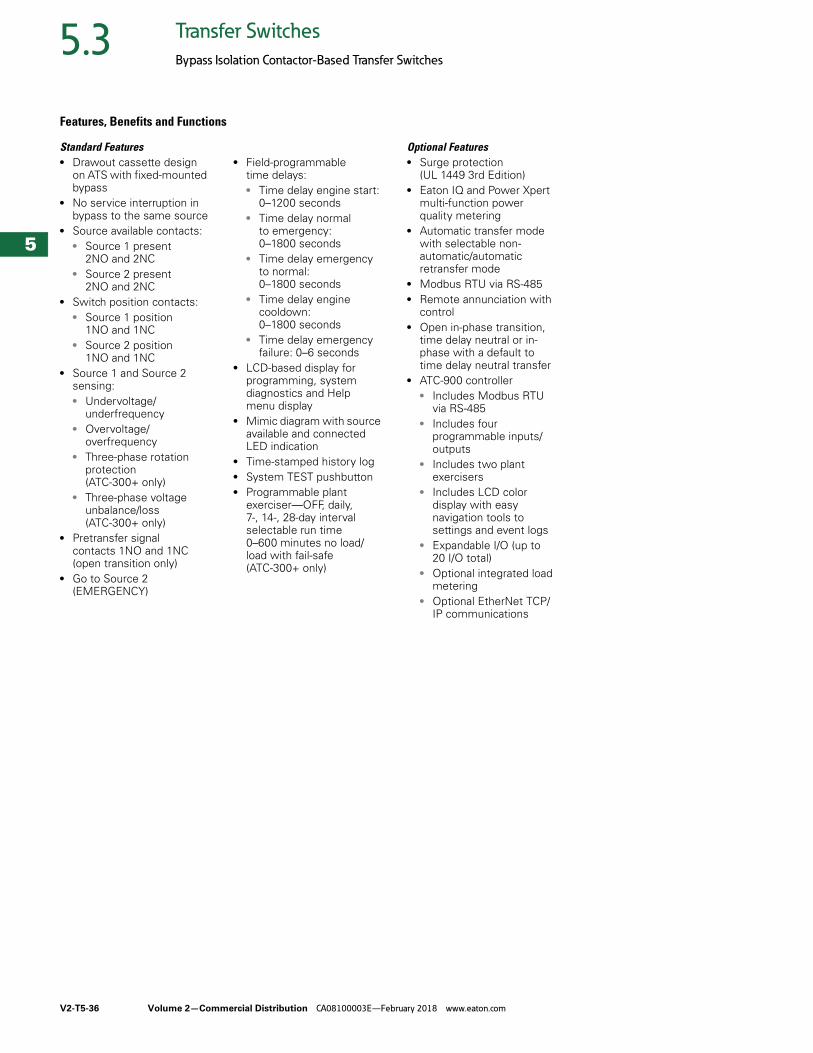
V2-T5-36 Volume 2—Commercial Distribution CA08100003E—February 2018 www.eaton.com
5
5
5
5
5
5
5
5
5
5
5
5
5
5
5
5
5
5
5
5
5
5
5
5
5
5
5
5
5
5
5.3 Transfer Switches
Bypass Isolation Contactor-Based Transfer Switches
Features, Benefits and Functions
Standard Features● Drawout cassette design
on ATS with fixed-mounted bypass
● No service interruption in bypass to the same source
● Source available contacts:● Source 1 present
2NO and 2NC● Source 2 present
2NO and 2NC● Switch position contacts:
● Source 1 position 1NO and 1NC
● Source 2 position 1NO and 1NC
● Source 1 and Source 2 sensing:● Undervoltage/
underfrequency● Overvoltage/
overfrequency● Three-phase rotation
protection (ATC-300+ only)
● Three-phase voltage unbalance/loss (ATC-300+ only)
● Pretransfer signal contacts 1NO and 1NC (open transition only)
● Go to Source 2 (EMERGENCY)
● Field-programmable time delays:● Time delay engine start:
0–1200 seconds● Time delay normal
to emergency: 0–1800 seconds
● Time delay emergency to normal: 0–1800 seconds
● Time delay engine cooldown: 0–1800 seconds
● Time delay emergency failure: 0–6 seconds
● LCD-based display for programming, system diagnostics and Help menu display
● Mimic diagram with source available and connected LED indication
● Time-stamped history log● System TEST pushbutton● Programmable plant
exerciser—OFF, daily, 7-, 14-, 28-day interval selectable run time 0–600 minutes no load/load with fail-safe(ATC-300+ only)
Optional Features● Surge protection
(UL 1449 3rd Edition)● Eaton IQ and Power Xpert
multi-function power quality metering
● Automatic transfer mode with selectable non-automatic/automatic retransfer mode
● Modbus RTU via RS-485● Remote annunciation with
control● Open in-phase transition,
time delay neutral or in-phase with a default to time delay neutral transfer
● ATC-900 controller● Includes Modbus RTU
via RS-485● Includes four
programmable inputs/outputs
● Includes two plant exercisers
● Includes LCD color display with easy navigation tools to settings and event logs
● Expandable I/O (up to 20 I/O total)
● Optional integrated load metering
● Optional EtherNet TCP/IP communications
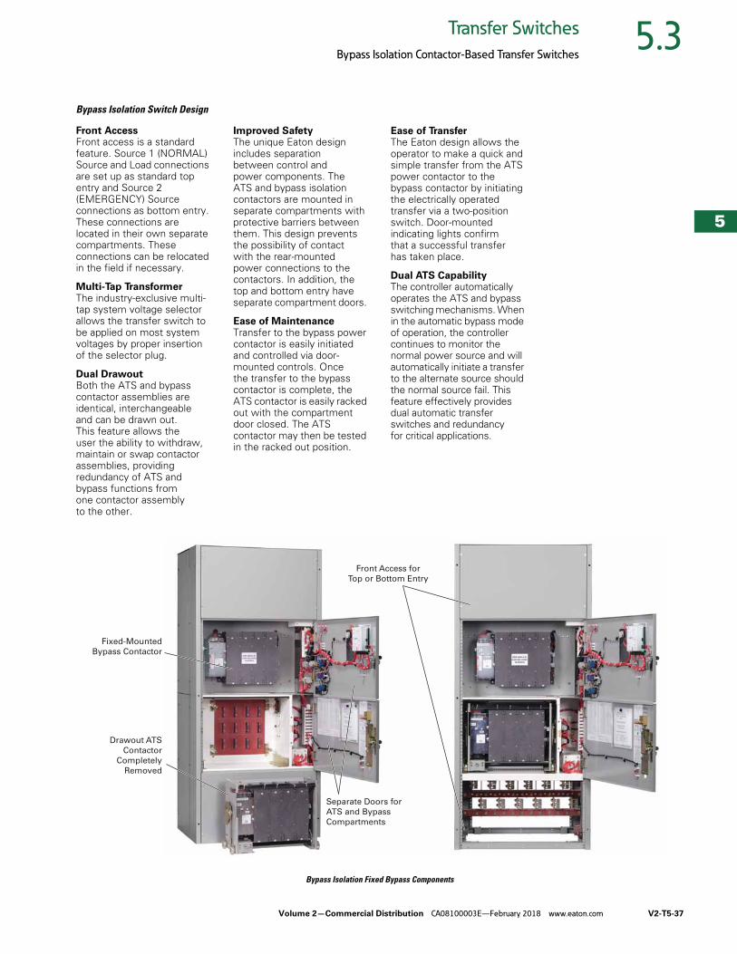
Volume 2—Commercial Distribution CA08100003E—February 2018 www.eaton.com V2-T5-37
5
5
5
5
5
5
5
5
5
5
5
5
5
5
5
5
5
5
5
5
5
5
5
5
5
5
5
5
5
5
5.3Transfer Switches
Bypass Isolation Contactor-Based Transfer Switches
Bypass Isolation Switch Design
Front AccessFront access is a standard feature. Source 1 (NORMAL) Source and Load connections are set up as standard top entry and Source 2 (EMERGENCY) Source connections as bottom entry. These connections are located in their own separate compartments. These connections can be relocated in the field if necessary.
Multi-Tap Transformer The industry-exclusive multi-tap system voltage selector allows the transfer switch to be applied on most system voltages by proper insertion of the selector plug.
Dual Drawout Both the ATS and bypass contactor assemblies are identical, interchangeable and can be drawn out. This feature allows the user the ability to withdraw, maintain or swap contactor assemblies, providing redundancy of ATS and bypass functions from one contactor assembly to the other.
Improved SafetyThe unique Eaton design includes separation between control and power components. The ATS and bypass isolation contactors are mounted in separate compartments with protective barriers between them. This design prevents the possibility of contact with the rear-mounted power connections to the contactors. In addition, the top and bottom entry have separate compartment doors.
Ease of MaintenanceTransfer to the bypass power contactor is easily initiated and controlled via door-mounted controls. Once the transfer to the bypass contactor is complete, the ATS contactor is easily racked out with the compartment door closed. The ATS contactor may then be tested in the racked out position.
Ease of TransferThe Eaton design allows the operator to make a quick and simple transfer from the ATS power contactor to the bypass contactor by initiating the electrically operated transfer via a two-position switch. Door-mounted indicating lights confirm that a successful transfer has taken place.
Dual ATS CapabilityThe controller automatically operates the ATS and bypass switching mechanisms. When in the automatic bypass mode of operation, the controller continues to monitor the normal power source and will automatically initiate a transfer to the alternate source should the normal source fail. This feature effectively provides dual automatic transfer switches and redundancy for critical applications.
Bypass Isolation Fixed Bypass Components
Fixed-Mounted
Bypass Contactor
Separate Doors for
ATS and Bypass
Compartments
Front Access for
Top or Bottom Entry
Drawout ATS
Contactor
Completely
Removed
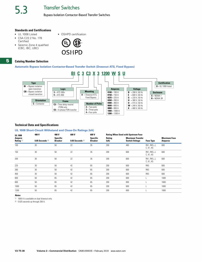
V2-T5-38 Volume 2—Commercial Distribution CA08100003E—February 2018 www.eaton.com
5
5
5
5
5
5
5
5
5
5
5
5
5
5
5
5
5
5
5
5
5
5
5
5
5
5
5
5
5
5
5.3 Transfer Switches
Bypass Isolation Contactor-Based Transfer Switches
Standards and Certifications● UL 1008 Listed● CSA C22.2 No. 178
Certified● Seismic Zone 4 qualified
(CBC, IBC, UBC)
● OSHPD certification
Catalog Number Selection
Automatic Bypass Isolation Contactor-Based Transfer Switch (Drawout ATS, Fixed Bypass)
Technical Data and Specifications
UL 1008 Short-Circuit Withstand and Close-On Ratings (kA)
Notes1 1600 A is available on dual drawout only.2 0.025 seconds up through 200 A.
UL 1008Ampere Rating 1
480 V 480 V 600 V 600 V Rating When Used with Upstream Fuse
0.05 Seconds 2Specific Breaker 0.05 Seconds 2
Specific Breaker
Rating (kA)
Maximum Transfer Switch Voltage Fuse Type
Maximum Fuse Amperes
100 30 50 22 35 200 480 RK1, RK5, J, C, K1, K5
600
150 30 50 22 35 200 600 RK1, RK5, J, C, K1, K5
600
200 30 50 22 35 200 600 RK1, RK5, J, C, K1, K5
600
225 30 50 42 65 200 600 RK5 600
260 30 50 42 65 200 600 RK5 600
400 30 50 42 65 200 600 RK5 600
600 50 65 42 65 200 600 L 1600
800 50 65 42 65 200 600 L 1600
1000 50 65 42 65 200 600 L 1600
1200 50 65 42 65 200 600 L 1600
TypeBI = Bypass isolation
open transitionCB = Bypass isolation
closed transition
Logic3 = ATC-300+9 = ATC-900
Amperes0100 = 100 A0150 = 150 A0225 = 225 A0260 = 260 A0400 = 400 A0600 = 600 A0800 = 800 A1000 = 1000 A1200 = 1200 A
VoltageB = 208 V, 60 HzE = 600 V, 60 HzG = 220 V, 50 HzH = 380 V, 50 HzO = 415 V, 50 HzW = 240 V, 60 HzX = 480 V, 60 Hz
CertificationU = UL 1008 listed
EnclosureS = NEMA 1R = NEMA 3R
OrientationC = Contactor
FrameC3 = Time delay neutral
(TDN) onlyC5 = In-phase/TDN transfer
MountingX = Drawout ATS,
Fixed Bypass
Number of Poles2 = Two-pole3 = Three-pole4 = Four-pole
BI C 3 C3 X 3 1200 W S U
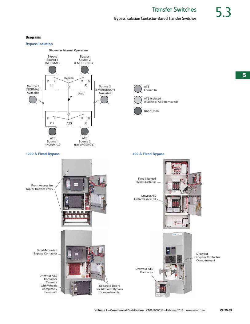
Volume 2—Commercial Distribution CA08100003E—February 2018 www.eaton.com V2-T5-39
5
5
5
5
5
5
5
5
5
5
5
5
5
5
5
5
5
5
5
5
5
5
5
5
5
5
5
5
5
5
5.3Transfer Switches
Bypass Isolation Contactor-Based Transfer Switches
Diagrams
Bypass Isolation
1200 A Fixed Bypass 400 A Fixed Bypass
Load
Bypass
ATS
(3) (4)
(1) (2)
Source 1(NORMAL)Available
Shown as Normal Operation
Source 2(EMERGENCY)
Available
BypassSource 1
(NORMAL)
ATSSource 1
(NORMAL)
ATSSource 2
(EMERGENCY)
BypassSource 2
(EMERGENCY)
ATSLocked In
Door Open
ATS Isolated(Flashing: ATS Removed)
Separate Doors for ATS and Bypass
Compartments
Fixed-Mounted Bypass Contactor
Drawout ATS Contactor
Cassette with Wheels Completely
Removed
Front Access for
Top or Bottom Entry
Drawout ATS
Contactor Rack Out
Fixed-Mounted
Bypass Contactor
Drawout Bypass Contactor Compartment
Drawout ATS Contactor
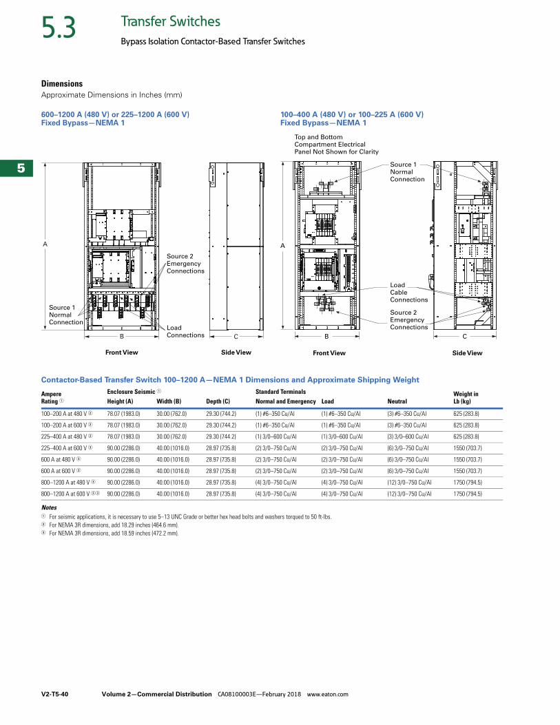
V2-T5-40 Volume 2—Commercial Distribution CA08100003E—February 2018 www.eaton.com
5
5
5
5
5
5
5
5
5
5
5
5
5
5
5
5
5
5
5
5
5
5
5
5
5
5
5
5
5
5
5.3 Transfer Switches
Bypass Isolation Contactor-Based Transfer Switches
DimensionsApproximate Dimensions in Inches (mm)
600–1200 A (480 V) or 225–1200 A (600 V) Fixed Bypass—NEMA 1
100–400 A (480 V) or 100–225 A (600 V) Fixed Bypass—NEMA 1
Contactor-Based Transfer Switch 100–1200 A—NEMA 1 Dimensions and Approximate Shipping Weight
Notes1 For seismic applications, it is necessary to use 5–13 UNC Grade or better hex head bolts and washers torqued to 50 ft-lbs.2 For NEMA 3R dimensions, add 18.29 inches (464.6 mm).3 For NEMA 3R dimensions, add 18.59 inches (472.2 mm).
Front View Side View
Source 1 Normal Connection
Load Connections
Source 2 Emergency Connections
B C
A
Source 1 Normal Connection
LoadCableConnections
Source 2 Emergency Connections
Top and Bottom Compartment Electrical Panel Not Shown for Clarity
CB
A
Front View Side View
AmpereRating 1
Enclosure Seismic 1 Standard Terminals Weight in Lb (kg)Height (A) Width (B) Depth (C) Normal and Emergency Load Neutral
100–200 A at 480 V 2 78.07 (1983.0) 30.00 (762.0) 29.30 (744.2) (1) #6–350 Cu/Al (1) #6–350 Cu/Al (3) #6–350 Cu/Al 625 (283.8)
100–200 A at 600 V 2 78.07 (1983.0) 30.00 (762.0) 29.30 (744.2) (1) #6–350 Cu/Al (1) #6–350 Cu/Al (3) #6–350 Cu/Al 625 (283.8)
225–400 A at 480 V 2 78.07 (1983.0) 30.00 (762.0) 29.30 (744.2) (1) 3/0–600 Cu/Al (1) 3/0–600 Cu/Al (3) 3/0–600 Cu/Al 625 (283.8)
225–400 A at 600 V 3 90.00 (2286.0) 40.00 (1016.0) 28.97 (735.8) (2) 3/0–750 Cu/Al (2) 3/0–750 Cu/Al (6) 3/0–750 Cu/Al 1550 (703.7)
600 A at 480 V 3 90.00 (2286.0) 40.00 (1016.0) 28.97 (735.8) (2) 3/0–750 Cu/Al (2) 3/0–750 Cu/Al (6) 3/0–750 Cu/Al 1550 (703.7)
600 A at 600 V 3 90.00 (2286.0) 40.00 (1016.0) 28.97 (735.8) (2) 3/0–750 Cu/Al (2) 3/0–750 Cu/Al (6) 3/0–750 Cu/Al 1550 (703.7)
800–1200 A at 480 V 3 90.00 (2286.0) 40.00 (1016.0) 28.97 (735.8) (4) 3/0–750 Cu/Al (4) 3/0–750 Cu/Al (12) 3/0–750 Cu/Al 1750 (794.5)
800–1200 A at 600 V 33 90.00 (2286.0) 40.00 (1016.0) 28.97 (735.8) (4) 3/0–750 Cu/Al (4) 3/0–750 Cu/Al (12) 3/0–750 Cu/Al 1750 (794.5)
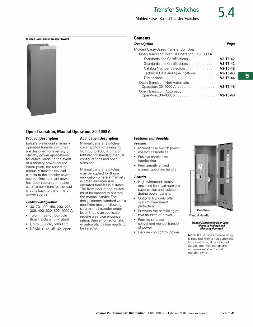
Volume 2—Commercial Distribution CA08100003E—February 2018 www.eaton.com V2-T5-41
5
5
5
5
5
5
5
5
5
5
5
5
5
5
5
5
5
5
5
5
5
5
5
5
5
5
5
5
5
5
5.4Transfer Switches
Molded Case–Based Transfer Switches
Molded Case–Based Transfer Switch ContentsDescription Page
Molded Case–Based Transfer SwitchesOpen Transition, Manual Operation, 30–1000 A
Standards and Certifications . . . . . . . . . . . . V2-T5-42
Standards and Certifications . . . . . . . . . . . . V2-T5-42
Catalog Number Selection . . . . . . . . . . . . . . V2-T5-42
Technical Data and Specifications . . . . . . . . V2-T5-43
Dimensions . . . . . . . . . . . . . . . . . . . . . . . . . V2-T5-44
Open Transition, Non-Automatic Operation, 30–1000 A . . . . . . . . . . . . . . . . . . . V2-T5-45
Open Transition, Automatic Operation, 30–1000 A . . . . . . . . . . . . . . . . . . . V2-T5-48
Open Transition, Manual Operation, 30–1000 AProduct DescriptionEaton’s wallmount manually operated transfer switches are designed for a variety of standby power applications for critical loads. In the event of a primary power source interruption, the user can manually transfer the load circuits to the standby power source. Once primary power has been restored, the user can manually transfer the load circuits back to the primary power source.
Product Configuration● 30, 70, 100, 150, 200, 225,
300, 400, 600, 800, 1000 A● Two-, three- or four-pole
(fourth pole is fully rated)● Up to 600 Vac, 50/60 Hz● NEMA 1, 12, 3R, 4X, open
Application DescriptionManual transfer switches cover applications ranging from 30 to 1000 A through 600 Vac for standard manual configurations and open transition.
Manual transfer switches may be applied for those application where a manually initiated and manually operated transfer is suitable. The front door of the switch must be opened to operate the manual handle. The design comes standard with a deadfront design, allowing safe manual transfer under load. Should an application require a service entrance rating, then a non-automatic or automatic design needs to be selected.
Features and BenefitsFeatures● Molded case switch power
contact assemblies● Positive mechanical
interlocking● Permanently affixed
manual operating handle
Benefits● High withstand, totally
enclosed for maximum arc suppression and isolation during power transfer
● Optional trip units offer system overcurrent protection
● Prevents the paralleling of two sources of power
● Permits safe and convenient manual transfer of power
● Requires no control power
Manual Switch with Door Open—Manually Initiated and
Manually Operated
Note: If a service entrance rating is required, then a non-automatic type switch must be selected. Service entrance ratings are not available on a manual transfer switch.
Manual Handle
Deadfront
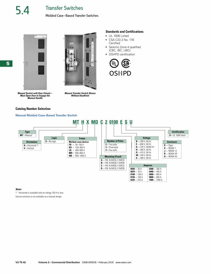
V2-T5-42 Volume 2—Commercial Distribution CA08100003E—February 2018 www.eaton.com
5
5
5
5
5
5
5
5
5
5
5
5
5
5
5
5
5
5
5
5
5
5
5
5
5
5
5
5
5
5
5.4 Transfer Switches
Molded Case–Based Transfer Switches
Manual Switch with Door Closed—Must Open Door to Engage the
Manual Handle
Manual Transfer Switch Shown Without Deadfront
Standards and Certifications● UL 1008 Listed● CSA C22.2 No. 178
Certified● Seismic Zone 4 qualified
(CBC, IBC, UBC)● OSHPD certification
Catalog Number Selection
Manual Molded Case–Based Transfer Switch
Notes1 Horizontal is available only on ratings 150 A or less.
Service entrance is not available on a manual design.
MT H X MD C 2 0100 E S U
TypeMT = Manual
OrientationH = Horizontal 1V = Vertical
LogicX = No logic
Mounting (Fixed)A = FM, N (MCS), E (MCS) B = FM, N (MCB), E (MCB)C = FM, N (MCB), E (MCS)D = FM, N (MCS), E (MCB)
Number of Poles2 = Two-pole3 = Three-pole4 = Four-pole
VoltageB = 208 V, 60 HzE = 600 V, 60 HzG = 220 V, 50/60 HzH = 380 V, 50 HzO = 415 V, 50 HzW = 240 V, 60 HzX = 480 V, 60 Hz
EnclosureK = OpenS = NEMA 1J = NEMA 12R = NEMA 3RD = NEMA 4X
CertificationU = UL 1008 listed
FrameMolded case deviceFD = 30–150 AKD = 150–300 ALD = 400–600 AMD = 600–800 ANB = 800–1000 A
Amperes0030 = 30 A0070 = 70 A0100 = 100 A0150 = 150 A0225 = 225 A
0300 = 300 A0400 = 400 A0600 = 600 A0800 = 800 A1000 = 1000 A
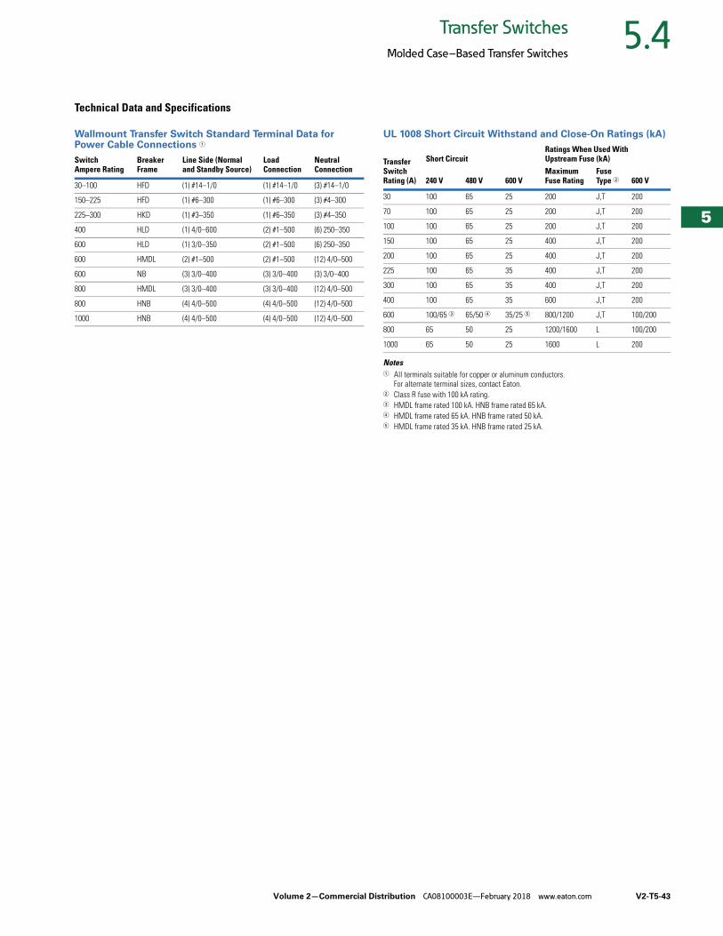
Volume 2—Commercial Distribution CA08100003E—February 2018 www.eaton.com V2-T5-43
5
5
5
5
5
5
5
5
5
5
5
5
5
5
5
5
5
5
5
5
5
5
5
5
5
5
5
5
5
5
5.4Transfer Switches
Molded Case–Based Transfer Switches
Technical Data and Specifications
Wallmount Transfer Switch Standard Terminal Data for Power Cable Connections 1
UL 1008 Short Circuit Withstand and Close-On Ratings (kA)
Notes1 All terminals suitable for copper or aluminum conductors.
For alternate terminal sizes, contact Eaton.2 Class R fuse with 100 kA rating.3 HMDL frame rated 100 kA. HNB frame rated 65 kA.4 HMDL frame rated 65 kA. HNB frame rated 50 kA.5 HMDL frame rated 35 kA. HNB frame rated 25 kA.
Switch Ampere Rating
BreakerFrame
Line Side (Normaland Standby Source)
LoadConnection
NeutralConnection
30–100 HFD (1) #14–1/0 (1) #14–1/0 (3) #14–1/0
150–225 HFD (1) #6–300 (1) #6–300 (3) #4–300
225–300 HKD (1) #3–350 (1) #6–350 (3) #4–350
400 HLD (1) 4/0–600 (2) #1–500 (6) 250–350
600 HLD (1) 3/0–350 (2) #1–500 (6) 250–350
600 HMDL (2) #1–500 (2) #1–500 (12) 4/0–500
600 NB (3) 3/0–400 (3) 3/0–400 (3) 3/0–400
800 HMDL (3) 3/0–400 (3) 3/0–400 (12) 4/0–500
800 HNB (4) 4/0–500 (4) 4/0–500 (12) 4/0–500
1000 HNB (4) 4/0–500 (4) 4/0–500 (12) 4/0–500
Transfer Switch Rating (A)
Short CircuitRatings When Used With Upstream Fuse (kA)
240 V 480 V 600 VMaximum Fuse Rating
Fuse Type 2 600 V
30 100 65 25 200 J,T 200
70 100 65 25 200 J,T 200
100 100 65 25 200 J,T 200
150 100 65 25 400 J,T 200
200 100 65 25 400 J,T 200
225 100 65 35 400 J,T 200
300 100 65 35 400 J,T 200
400 100 65 35 600 J,T 200
600 100/65 3 65/50 4 35/25 5 800/1200 J,T 100/200
800 65 50 25 1200/1600 L 100/200
1000 65 50 25 1600 L 200
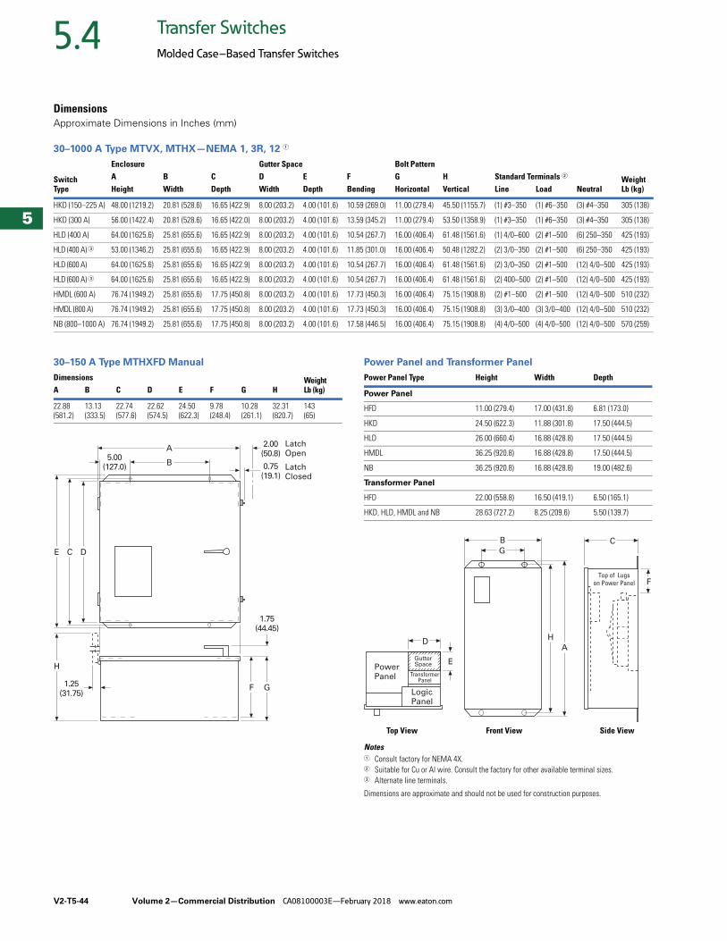
V2-T5-44 Volume 2—Commercial Distribution CA08100003E—February 2018 www.eaton.com
5
5
5
5
5
5
5
5
5
5
5
5
5
5
5
5
5
5
5
5
5
5
5
5
5
5
5
5
5
5
5.4 Transfer Switches
Molded Case–Based Transfer Switches
DimensionsApproximate Dimensions in Inches (mm)
30–1000 A Type MTVX, MTHX—NEMA 1, 3R, 12 1
30–150 A Type MTHXFD Manual Power Panel and Transformer Panel
Notes1 Consult factory for NEMA 4X.2 Suitable for Cu or Al wire. Consult the factory for other available terminal sizes.3 Alternate line terminals.
Dimensions are approximate and should not be used for construction purposes.
SwitchType
Enclosure Gutter Space Bolt PatternStandard Terminals 2 Weight
Lb (kg)A B C D E F G HHeight Width Depth Width Depth Bending Horizontal Vertical Line Load Neutral
HKD (150–225 A) 48.00 (1219.2) 20.81 (528.6) 16.65 (422.9) 8.00 (203.2) 4.00 (101.6) 10.59 (269.0) 11.00 (279.4) 45.50 (1155.7) (1) #3–350 (1) #6–350 (3) #4–350 305 (138)
HKD (300 A) 56.00 (1422.4) 20.81 (528.6) 16.65 (422.0) 8.00 (203.2) 4.00 (101.6) 13.59 (345.2) 11.00 (279.4) 53.50 (1358.9) (1) #3–350 (1) #6–350 (3) #4–350 305 (138)
HLD (400 A) 64.00 (1625.6) 25.81 (655.6) 16.65 (422.9) 8.00 (203.2) 4.00 (101.6) 10.54 (267.7) 16.00 (406.4) 61.48 (1561.6) (1) 4/0–600 (2) #1–500 (6) 250–350 425 (193)
HLD (400 A) 3 53.00 (1346.2) 25.81 (655.6) 16.65 (422.9) 8.00 (203.2) 4.00 (101.6) 11.85 (301.0) 16.00 (406.4) 50.48 (1282.2) (2) 3/0–350 (2) #1–500 (6) 250–350 425 (193)
HLD (600 A) 64.00 (1625.6) 25.81 (655.6) 16.65 (422.9) 8.00 (203.2) 4.00 (101.6) 10.54 (267.7) 16.00 (406.4) 61.48 (1561.6) (2) 3/0–350 (2) #1–500 (12) 4/0–500 425 (193)
HLD (600 A) 3 64.00 (1625.6) 25.81 (655.6) 16.65 (422.9) 8.00 (203.2) 4.00 (101.6) 10.54 (267.7) 16.00 (406.4) 61.48 (1561.6) (2) 400–500 (2) #1–500 (12) 4/0–500 425 (193)
HMDL (600 A) 76.74 (1949.2) 25.81 (655.6) 17.75 (450.8) 8.00 (203.2) 4.00 (101.6) 17.73 (450.3) 16.00 (406.4) 75.15 (1908.8) (2) #1–500 (2) #1–500 (12) 4/0–500 510 (232)
HMDL (800 A) 76.74 (1949.2) 25.81 (655.6) 17.75 (450.8) 8.00 (203.2) 4.00 (101.6) 17.73 (450.3) 16.00 (406.4) 75.15 (1908.8) (3) 3/0–400 (3) 3/0–400 (12) 4/0–500 510 (232)
NB (800–1000 A) 76.74 (1949.2) 25.81 (655.6) 17.75 (450.8) 8.00 (203.2) 4.00 (101.6) 17.58 (446.5) 16.00 (406.4) 75.15 (1908.8) (4) 4/0–500 (4) 4/0–500 (12) 4/0–500 570 (259)
Dimensions WeightLb (kg)A B C D E F G H
22.88(581.2)
13.13(333.5)
22.74(577.6)
22.62(574.5)
24.50(622.3)
9.78(248.4)
10.28(261.1)
32.31(820.7)
143(65)
5.00(127.0)
E C D
A
B
F G
1.75(44.45)
1.25(31.75)
H
0.75(19.1)
LatchClosed
2.00(50.8)
LatchOpen
Power Panel Type Height Width Depth
Power Panel
HFD 11.00 (279.4) 17.00 (431.8) 6.81 (173.0)
HKD 24.50 (622.3) 11.88 (301.8) 17.50 (444.5)
HLD 26.00 (660.4) 16.88 (428.8) 17.50 (444.5)
HMDL 36.25 (920.8) 16.88 (428.8) 17.50 (444.5)
NB 36.25 (920.8) 16.88 (428.8) 19.00 (482.6)
Transformer Panel
HFD 22.00 (558.8) 16.50 (419.1) 6.50 (165.1)
HKD, HLD, HMDL and NB 28.63 (727.2) 8.25 (209.6) 5.50 (139.7)
LogicPanel
D
EPowerPanel Transformer
Panel
B
G
A
H
C
FTop of Lugs
on Power Panel
GutterSpace
Front View Side ViewTop View
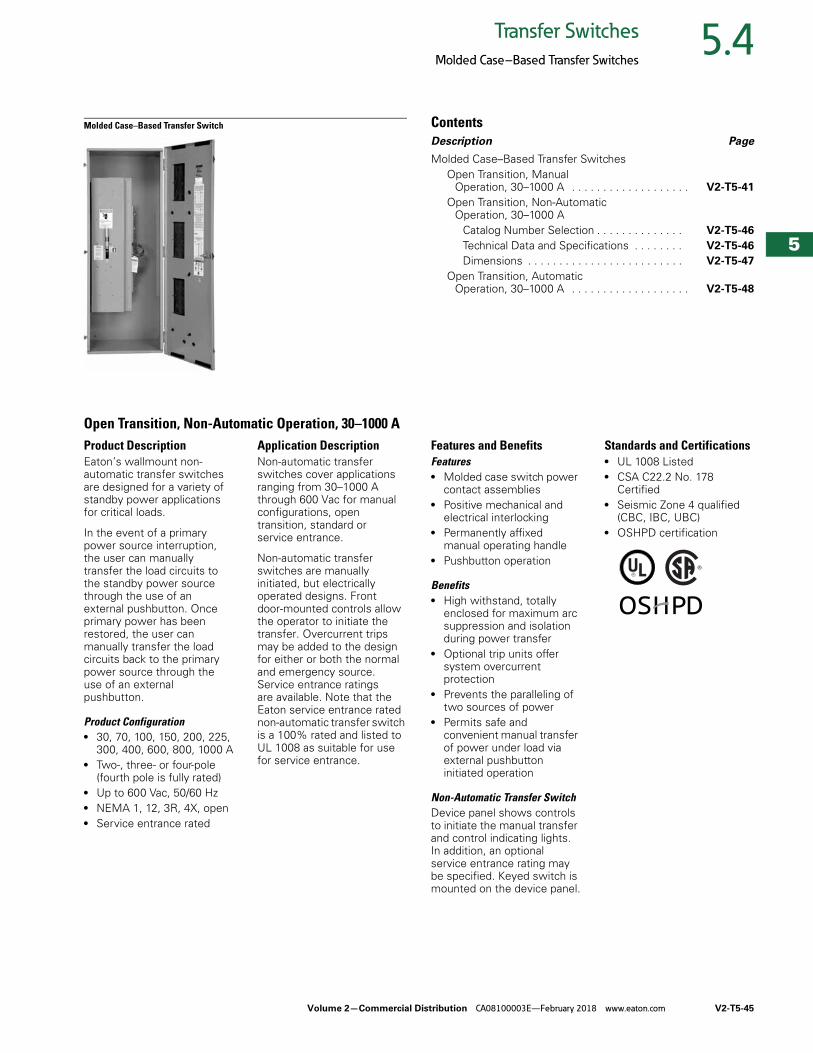
Volume 2—Commercial Distribution CA08100003E—February 2018 www.eaton.com V2-T5-45
5
5
5
5
5
5
5
5
5
5
5
5
5
5
5
5
5
5
5
5
5
5
5
5
5
5
5
5
5
5
5.4Transfer Switches
Molded Case–Based Transfer Switches
Molded Case–Based Transfer Switch ContentsDescription Page
Molded Case–Based Transfer SwitchesOpen Transition, Manual
Operation, 30–1000 A . . . . . . . . . . . . . . . . . . . V2-T5-41
Open Transition, Non-Automatic Operation, 30–1000 A
Catalog Number Selection . . . . . . . . . . . . . . V2-T5-46
Technical Data and Specifications . . . . . . . . V2-T5-46
Dimensions . . . . . . . . . . . . . . . . . . . . . . . . . V2-T5-47
Open Transition, Automatic Operation, 30–1000 A . . . . . . . . . . . . . . . . . . . V2-T5-48
Open Transition, Non-Automatic Operation, 30–1000 AProduct DescriptionEaton’s wallmount non-automatic transfer switches are designed for a variety of standby power applications for critical loads.
In the event of a primary power source interruption, the user can manually transfer the load circuits to the standby power source through the use of an external pushbutton. Once primary power has been restored, the user can manually transfer the load circuits back to the primary power source through the use of an external pushbutton.
Product Configuration● 30, 70, 100, 150, 200, 225,
300, 400, 600, 800, 1000 A● Two-, three- or four-pole
(fourth pole is fully rated)● Up to 600 Vac, 50/60 Hz● NEMA 1, 12, 3R, 4X, open● Service entrance rated
Application DescriptionNon-automatic transfer switches cover applications ranging from 30–1000 A through 600 Vac for manual configurations, open transition, standard or service entrance.
Non-automatic transfer switches are manually initiated, but electrically operated designs. Front door-mounted controls allow the operator to initiate the transfer. Overcurrent trips may be added to the design for either or both the normal and emergency source. Service entrance ratings are available. Note that the Eaton service entrance rated non-automatic transfer switch is a 100% rated and listed to UL 1008 as suitable for use for service entrance.
Features and Benefits Features● Molded case switch power
contact assemblies● Positive mechanical and
electrical interlocking● Permanently affixed
manual operating handle● Pushbutton operation
Benefits● High withstand, totally
enclosed for maximum arc suppression and isolation during power transfer
● Optional trip units offer system overcurrent protection
● Prevents the paralleling of two sources of power
● Permits safe and convenient manual transfer of power under load via external pushbutton initiated operation
Non-Automatic Transfer SwitchDevice panel shows controls to initiate the manual transfer and control indicating lights. In addition, an optional service entrance rating may be specified. Keyed switch is mounted on the device panel.
Standards and Certifications● UL 1008 Listed● CSA C22.2 No. 178
Certified● Seismic Zone 4 qualified
(CBC, IBC, UBC)● OSHPD certification
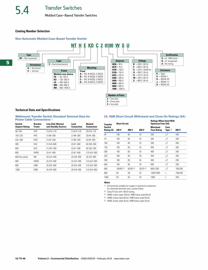
V2-T5-46 Volume 2—Commercial Distribution CA08100003E—February 2018 www.eaton.com
5
5
5
5
5
5
5
5
5
5
5
5
5
5
5
5
5
5
5
5
5
5
5
5
5
5
5
5
5
5
5.4 Transfer Switches
Molded Case–Based Transfer Switches
Catalog Number Selection
Non-Automatic Molded Case–Based Transfer Switch
Technical Data and Specifications
Wallmount Transfer Switch Standard Terminal Data for Power Cable Connections 1
UL 1008 Short Circuit Withstand and Close-On Ratings (kA)
Notes1 All terminals suitable for copper or aluminum conductors.
For alternate terminal sizes, contact Eaton.2 Class R fuse with 100 kA rating.3 HMDL frame rated 100 kA. HNB frame rated 65 kA.4 HMDL frame rated 65 kA. HNB frame rated 50 kA.5 HMDL frame rated 35 kA. HNB frame rated 25 kA.
TypeNT = Non-automatic
OrientationH = HorizontalV = Vertical
LogicE = Electromechanical
EnclosureK = OpenS = NEMA 1R = NEMA 3RJ = NEMA 12D = NEMA 4X
CertificationU = UL 1008 listedR = UL recognizedX = No listing
NT H E KD C 2 0100 W S U
MountingFixedA = FM, N (MCS), E (MCS)B = FM, N (MCB), E (MCB)C = FM, N (MCB), E (MCS)D = FM, N (MCS), E (MCB)
Number of Poles2 = Two-pole3 = Three-pole4 = Four-pole
FrameMolded case deviceFD = 30–150 AKD = 150–300 ALD = 400–600 AMD = 600–800 ANB = 800–1000 A
Amperes0030 = 30 A0070 = 70 A0100 = 100 A0150 = 150 A0225 = 225 A0300 = 300 A0400 = 400 A0600 = 600 A0800 = 800 A1000 = 1000 A
VoltageB = 208 V, 60 HzE = 600 V, 60 HzG = 220 V, 50/60 HzH = 380 V, 50 HzO = 415 V, 50 HzW = 240 V, 60 HzX = 480 V, 60 Hz
SwitchAmpere Rating
BreakerFrame
Line Side (Normaland Standby Source)
LoadConnection
NeutralConnection
30–100 HFD (1) #14–1/0 (1) #14–1/0 (3) #14–1/0
150–225 HFD (1) #6–300 (1) #6–300 (3) #4–300
225–300 HKD (1) #3–350 (1) #6–350 (3) #4–350
400 HLD (1) 4/0–600 (2) #1–500 (6) 250–350
600 HLD (1) 3/0–350 (2) #1–500 (6) 250–350
600 HMDL (2) #1–500 (2) #1–500 (12) 4/0–500
600 (four-pole) NB (3) 3/0–400 (3) 3/0–400 (3) 3/0–400
800 HMDL (3) 3/0–400 (3) 3/0–400 (12) 4/0–500
800 HNB (4) 4/0–500 (4) 4/0–500 (12) 4/0–500
1000 HNB (4) 4/0–500 (4) 4/0–500 (12) 4/0–500
Transfer Switch Rating (A)
Short CircuitRatings When Used With Upstream Fuse (kA)
240 V 480 V 600 VMaximum Fuse Rating
Fuse Type 2 600 V
30 100 65 25 200 J,T 200
70 100 65 25 200 J,T 200
100 100 65 25 200 J,T 200
150 100 65 25 400 J,T 200
200 100 65 25 400 J,T 200
225 100 65 35 400 J,T 200
300 100 65 35 400 J,T 200
400 100 65 35 600 J,T 200
600 100/65 3 65/50 4 35/25 5 800/1200 J,T 100/200
800 65 50 25 1200/1600 L 100/200
1000 65 50 25 1600 L 200
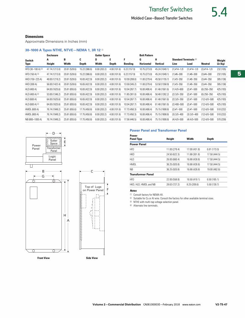
Volume 2—Commercial Distribution CA08100003E—February 2018 www.eaton.com V2-T5-47
5
5
5
5
5
5
5
5
5
5
5
5
5
5
5
5
5
5
5
5
5
5
5
5
5
5
5
5
5
5
5.4Transfer Switches
Molded Case–Based Transfer Switches
DimensionsApproximate Dimensions in Inches (mm)
30–1000 A Types NTHE, NTVE—NEMA 1, 3R 12 1
Power Panel and Transformer Panel
Notes1 Consult factory for NEMA 4X.2 Suitable for Cu or Al wire. Consult the factory for other available terminal sizes.3 NTHE with multi-tap voltage selection panel.4 Alternate line terminals.
SwitchType
Enclosure Gutter Space Bolt PatternStandard Terminals 2 Weight
Lb (kg)A B C D E F G HHeight Width Depth Width Depth Bending Horizontal Vertical Line Load Neutral
HFD (30–100 A) 3 47.74 (1213.0) 20.81 (528.6) 15.22 (386.6) 8.00 (203.2) 4.00 (101.6) 6.22 (157.9) 10.75 (273.0) 45.24 (1049.1) (1) #14–1/0 (1) #14–1/0 (3) #14–1/0 232 (105)
HFD (150 A) 3 47.74 (1213.0) 20.81 (528.6) 15.22 (386.6) 8.00 (203.2) 4.00 (101.6) 6.22 (157.9) 10.75 (273.0) 45.24 (1049.1) (1) #6–300 (1) #6–300 (3) #4–300 232 (105)
HKD (150–225 A) 48.00 (1219.2) 20.81 (528.6) 16.65 (422.9) 8.00 (203.2) 4.00 (101.6) 10.59 (269.0) 11.00 (279.4) 45.50 (1155.7) (1) #3–350 (1) #6–350 (3) #4–350 305 (138)
HKD (300 A) 56.00 (1422.4) 20.81 (528.6) 16.65 (422.9) 8.00 (203.2) 4.00 (101.6) 13.59 (345.2) 11.00 (279.4) 53.50 (1358.9) (1) #3–350 (1) #6–350 (3) #4–350 305 (138)
HLD (400 A) 64.00 (1625.6) 25.81 (655.6) 16.65 (422.9) 8.00 (203.2) 4.00 (101.6) 10.54 (267.7) 16.00 (406.4) 61.48 (1561.6) (1) 4/0–600 (2) #1–500 (6) 250–350 425 (193)
HLD (400 A) 4 53.00 (1346.2) 25.81 (655.6) 16.65 (422.9) 8.00 (203.2) 4.00 (101.6) 11.85 (301.0) 16.00 (406.4) 50.48 (1282.2) (2) 3/0–350 (2) #1–500 (6) 250–350 425 (193)
HLD (600 A) 64.00 (1625.6) 25.81 (655.6) 16.65 (422.9) 8.00 (203.2) 4.00 (101.6) 10.54 (267.7) 16.00 (406.4) 61.48 (1561.6) (2) 3/0–350 (2) #1–500 (12) 4/0–500 425 (193)
HLD (600 A) 4 64.00 (1625.6) 25.81 (655.6) 16.65 (422.9) 8.00 (203.2) 4.00 (101.6) 10.54 (267.7) 16.00 (406.4) 61.48 (1561.6) (2) 400–500 (2) #1–500 (12) 4/0–500 425 (193)
HMDL (600 A) 76.74 (1949.2) 25.81 (655.6) 17.75 (450.8) 8.00 (203.2) 4.00 (101.6) 17.73 (450.3) 16.00 (406.4) 75.15 (1908.8) (2) #1–500 (2) #1–500 (12) 4/0–500 510 (232)
HMDL (800 A) 76.74 (1949.2) 25.81 (655.6) 17.75 (450.8) 8.00 (203.2) 4.00 (101.6) 17.73 (450.3) 16.00 (406.4) 75.15 (1908.8) (3) 3/0–400 (3) 3/0–400 (12) 4/0–500 510 (232)
NB (800–1000 A) 76.74 (1949.2) 25.81 (655.6) 17.75 (450.8) 8.00 (203.2) 4.00 (101.6) 17.58 (446.5) 16.00 (406.4) 75.15 (1908.8) (4) 4/0–500 (4) 4/0–500 (12) 4/0–500 570 (259)
B
G
A
H
C
FTop of Lugs
on Power Panel
TransformerPanel
LogicPanel
D
EPowerPanel
GutterSpace
Front View Side View
Power Panel Type Height Width Depth
Power Panel
HFD 11.00 (279.4) 17.00 (431.8) 6.81 (173.0)
HKD 24.50 (622.3) 11.88 (301.8) 17.50 (444.5)
HLD 26.00 (660.4) 16.88 (428.8) 17.50 (444.5)
HMDL 36.25 (920.8) 16.88 (428.8) 17.50 (444.5)
NB 36.25 (920.8) 16.88 (428.8) 19.00 (482.6)
Transformer Panel
HFD 22.00 (558.8) 16.50 (419.1) 6.50 (165.1)
HKD, HLD, HMDL and NB 28.63 (727.2) 8.25 (209.6) 5.50 (139.7)
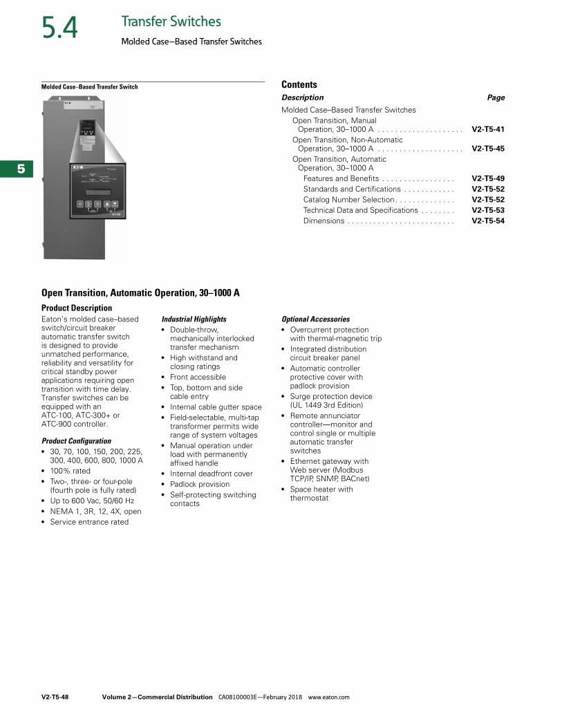
V2-T5-48 Volume 2—Commercial Distribution CA08100003E—February 2018 www.eaton.com
5
5
5
5
5
5
5
5
5
5
5
5
5
5
5
5
5
5
5
5
5
5
5
5
5
5
5
5
5
5
5.4 Transfer Switches
Molded Case–Based Transfer Switches
Molded Case–Based Transfer Switch ContentsDescription Page
Molded Case–Based Transfer SwitchesOpen Transition, Manual
Operation, 30–1000 A . . . . . . . . . . . . . . . . . . . . V2-T5-41
Open Transition, Non-Automatic Operation, 30–1000 A . . . . . . . . . . . . . . . . . . . . V2-T5-45
Open Transition, Automatic Operation, 30–1000 A
Features and Benefits . . . . . . . . . . . . . . . . . V2-T5-49
Standards and Certifications . . . . . . . . . . . . V2-T5-52
Catalog Number Selection . . . . . . . . . . . . . . V2-T5-52
Technical Data and Specifications . . . . . . . . V2-T5-53
Dimensions . . . . . . . . . . . . . . . . . . . . . . . . . V2-T5-54
Open Transition, Automatic Operation, 30–1000 AProduct DescriptionEaton’s molded case–based switch/circuit breaker automatic transfer switch is designed to provide unmatched performance, reliability and versatility for critical standby power applications requiring open transition with time delay. Transfer switches can be equipped with an ATC-100, ATC-300+ orATC-900 controller.
Product Configuration● 30, 70, 100, 150, 200, 225,
300, 400, 600, 800, 1000 A ● 100% rated● Two-, three- or four-pole
(fourth pole is fully rated)● Up to 600 Vac, 50/60 Hz● NEMA 1, 3R, 12, 4X, open ● Service entrance rated
Industrial Highlights● Double-throw,
mechanically interlocked transfer mechanism
● High withstand and closing ratings
● Front accessible● Top, bottom and side
cable entry● Internal cable gutter space ● Field-selectable, multi-tap
transformer permits wide range of system voltages
● Manual operation under load with permanently affixed handle
● Internal deadfront cover● Padlock provision● Self-protecting switching
contacts
Optional Accessories● Overcurrent protection
with thermal-magnetic trip ● Integrated distribution
circuit breaker panel● Automatic controller
protective cover with padlock provision
● Surge protection device (UL 1449 3rd Edition)
● Remote annunciator controller—monitor and control single or multiple automatic transfer switches
● Ethernet gateway with Web server (Modbus TCP/IP, SNMP, BACnet)
● Space heater with thermostat
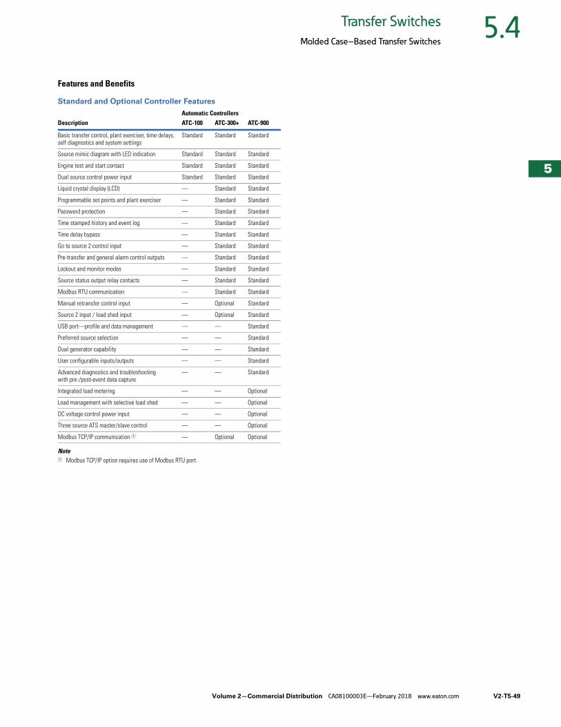
Volume 2—Commercial Distribution CA08100003E—February 2018 www.eaton.com V2-T5-49
5
5
5
5
5
5
5
5
5
5
5
5
5
5
5
5
5
5
5
5
5
5
5
5
5
5
5
5
5
5
5.4Transfer Switches
Molded Case–Based Transfer Switches
Features and Benefits
Standard and Optional Controller Features
Note1 Modbus TCP/IP option requires use of Modbus RTU port.
Automatic ControllersDescription ATC-100 ATC-300+ ATC-900
Basic transfer control, plant exerciser, time delays, self diagnostics and system settings
Standard Standard Standard
Source mimic diagram with LED indication Standard Standard Standard
Engine test and start contact Standard Standard Standard
Dual source control power input Standard Standard Standard
Liquid crystal display (LCD) — Standard Standard
Programmable set points and plant exerciser — Standard Standard
Password protection — Standard Standard
Time stamped history and event log — Standard Standard
Time delay bypass — Standard Standard
Go to source 2 control input — Standard Standard
Pre-transfer and general alarm control outputs — Standard Standard
Lockout and monitor modes — Standard Standard
Source status output relay contacts — Standard Standard
Modbus RTU communication — Standard Standard
Manual retransfer control input — Optional Standard
Source 2 input / load shed input — Optional Standard
USB port—profile and data management — — Standard
Preferred source selection — — Standard
Dual generator capability — — Standard
User configurable inputs/outputs — — Standard
Advanced diagnostics and troubleshooting with pre-/post-event data capture
— — Standard
Integrated load metering — — Optional
Load management with selective load shed — — Optional
DC voltage control power input — — Optional
Three source ATS master/slave control — — Optional
Modbus TCP/IP communication 1 — Optional Optional
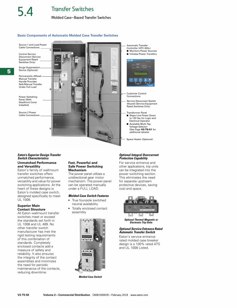
V2-T5-50 Volume 2—Commercial Distribution CA08100003E—February 2018 www.eaton.com
5
5
5
5
5
5
5
5
5
5
5
5
5
5
5
5
5
5
5
5
5
5
5
5
5
5
5
5
5
5
5.4 Transfer Switches
Molded Case–Based Transfer Switches
Basic Components of Automatic Molded Case Transfer Switches
Eaton’s Superior Design Transfer Switch CharacteristicsUnmatched Performance and VersatilityEaton’s family of wallmount transfer switches offers unmatched performance, versatility and value for power switching applications. At the heart of these designs is Eaton’s molded case switch, designed specifically to meet UL 1008.
Superior Main Contact StructureAll Eaton wallmount transfer switches meet or exceed the standards set forth in UL 1008 and UL 489. No other transfer switch manufacturer has met the rigid testing requirements of this combination of standards. Completely enclosed contacts add a measure of safety and reliability. It also ensures the integrity of the contact assemblies and minimizes the need for periodic maintenance of the contacts, reducing downtime.
Fast, Powerful and Safe Power Switching MechanismThe power panel utilizes a unidirectional gear motor mechanism. The power panel can be operated manually under a FULL LOAD.
Molded Case Switch Features● True four-pole switched
neutral availability● Totally enclosed contact
assembly
Molded Case Switch
Optional Integral Overcurrent Protection CapabilityFor service entrance and other applications, trip units can be integrated into the power switching section. This eliminates the need for separate upstream protective devices, saving cost and space.
Optional Thermal-Magnetic or Electronic Trip Units
Optional Service Entrance Rated Automatic Transfer SwitchEaton’s service entrance rated molded case breaker design is a 100% rated ATS and UL 1008 Listed.
Source 1 and Load Power
Cable Connections
Power Switching
Panel (With
Deadfront Cover
Installed)
Permanently Affixed
Manual Transfer
Handle Provides
Safe Manual Transfer
Under Full Load
Source 2 Power
Cable Connections
Automatic Transfer
Controller (ATC-300+)
■ Monitors Power Sources
■ Initiates Power Transfers
Service Disconnect Switch
(Keyed) (Service Equipment
Rated Switches Only)
Transformer Panel
■ Steps Line Power Down
to 120 Vac for Logic and
Electrical Operator
■ Available Multi-Tap
Voltage Selector
(See Page V2-T5-51 for
additional details)
Space Heater (Optional)
Customer Control
Connections
Surge Suppression
Device (Optional)
Control Service
Disconnect (Service
Equipment Rated
Switches Only)
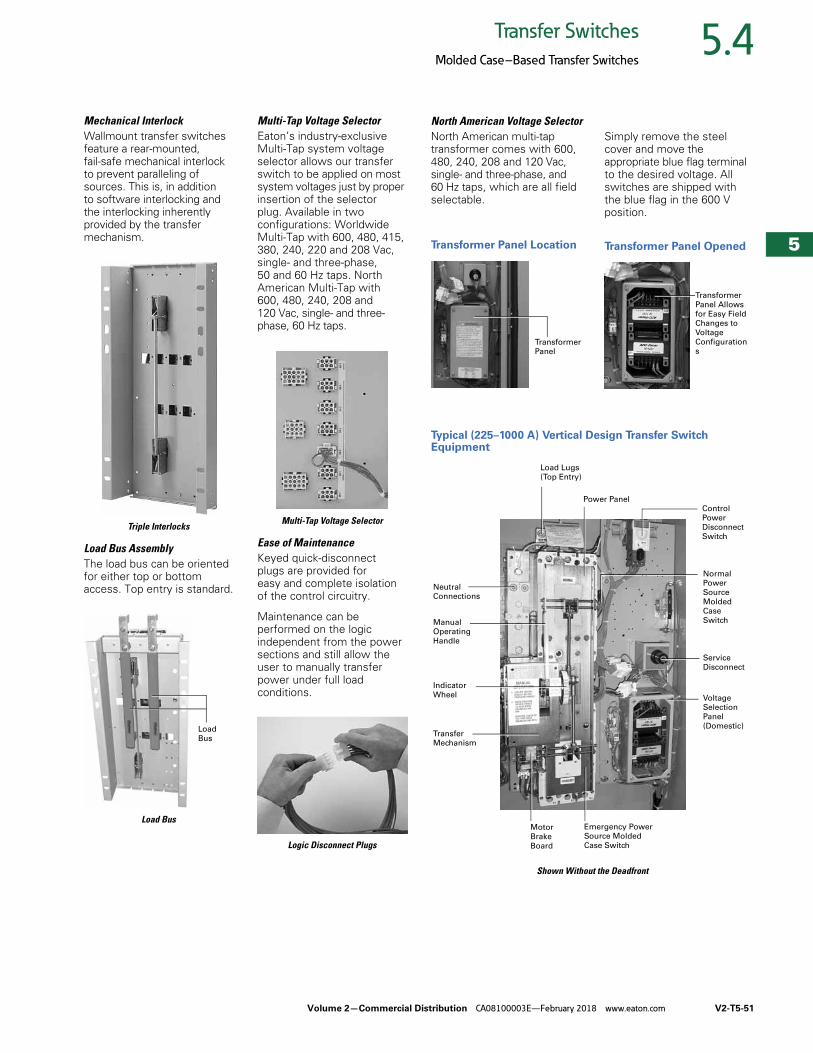
Volume 2—Commercial Distribution CA08100003E—February 2018 www.eaton.com V2-T5-51
5
5
5
5
5
5
5
5
5
5
5
5
5
5
5
5
5
5
5
5
5
5
5
5
5
5
5
5
5
5
5.4Transfer Switches
Molded Case–Based Transfer Switches
Mechanical InterlockWallmount transfer switches feature a rear-mounted, fail-safe mechanical interlock to prevent paralleling of sources. This is, in addition to software interlocking and the interlocking inherently provided by the transfer mechanism.
Triple Interlocks
Load Bus AssemblyThe load bus can be oriented for either top or bottom access. Top entry is standard.
Load Bus
Multi-Tap Voltage SelectorEaton’s industry-exclusive Multi-Tap system voltage selector allows our transfer switch to be applied on most system voltages just by proper insertion of the selector plug. Available in two configurations: Worldwide Multi-Tap with 600, 480, 415, 380, 240, 220 and 208 Vac, single- and three-phase, 50 and 60 Hz taps. North American Multi-Tap with 600, 480, 240, 208 and 120 Vac, single- and three-phase, 60 Hz taps.
Multi-Tap Voltage Selector
Ease of MaintenanceKeyed quick-disconnect plugs are provided for easy and complete isolation of the control circuitry.
Maintenance can be performed on the logic independent from the power sections and still allow the user to manually transfer power under full load conditions.
Logic Disconnect Plugs
Load
Bus
North American Voltage SelectorNorth American multi-tap transformer comes with 600, 480, 240, 208 and 120 Vac, single- and three-phase, and 60 Hz taps, which are all field selectable.
Transformer Panel Location
Simply remove the steel cover and move the appropriate blue flag terminal to the desired voltage. All switches are shipped with the blue flag in the 600 V position.
Transformer Panel Opened
Typical (225–1000 A) Vertical Design Transfer Switch Equipment
Shown Without the Deadfront
Transformer
Panel
Transformer
Panel Allows
for Easy Field
Changes to
Voltage
Configuration
s
Load Lugs
(Top Entry)
Neutral
Connections
Manual
Operating
Handle
Indicator
Wheel
Transfer
Mechanism
Motor
Brake
Board
Power Panel
Emergency Power
Source Molded
Case Switch
Voltage
Selection
Panel
(Domestic)
Service
Disconnect
Normal
Power
Source
Molded
Case
Switch
Control
Power
Disconnect
Switch
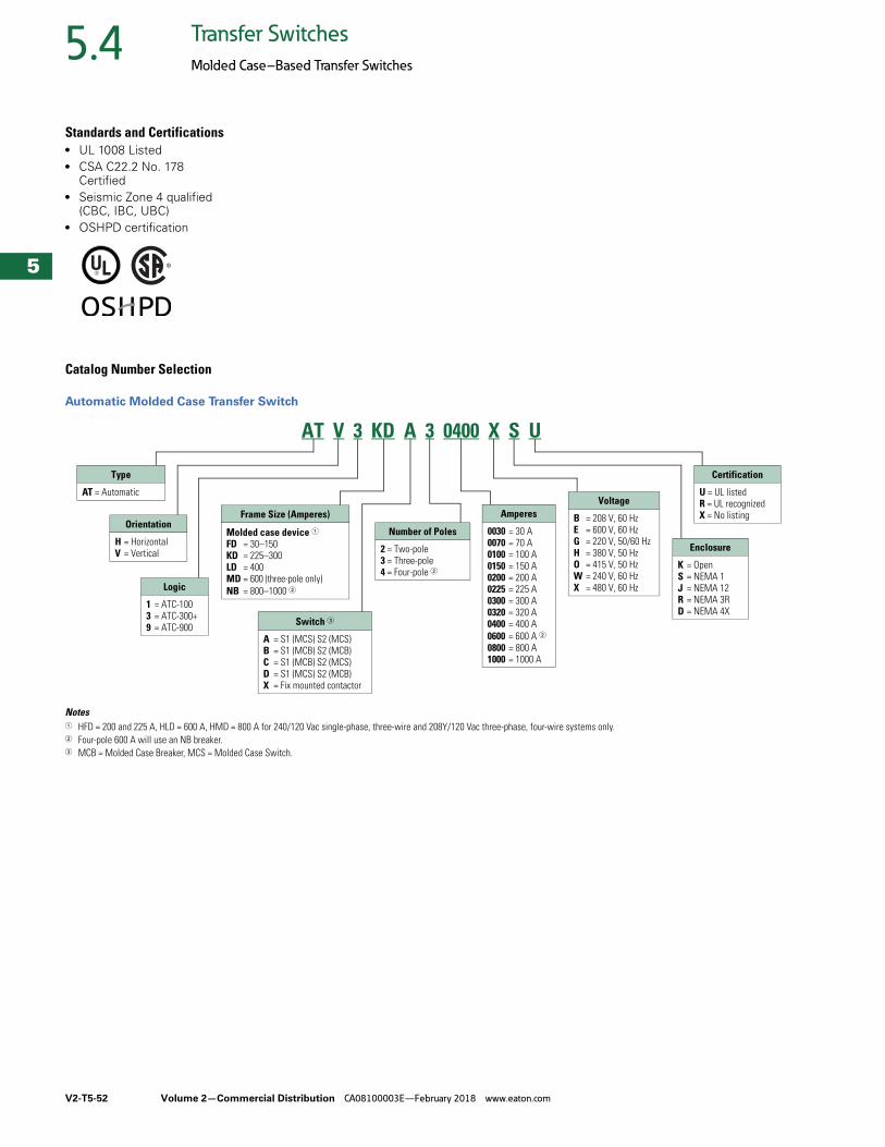
V2-T5-52 Volume 2—Commercial Distribution CA08100003E—February 2018 www.eaton.com
5
5
5
5
5
5
5
5
5
5
5
5
5
5
5
5
5
5
5
5
5
5
5
5
5
5
5
5
5
5
5.4 Transfer Switches
Molded Case–Based Transfer Switches
Standards and Certifications● UL 1008 Listed● CSA C22.2 No. 178
Certified● Seismic Zone 4 qualified
(CBC, IBC, UBC)● OSHPD certification
Catalog Number Selection
Automatic Molded Case Transfer Switch
Notes1 HFD = 200 and 225 A, HLD = 600 A, HMD = 800 A for 240/120 Vac single-phase, three-wire and 208Y/120 Vac three-phase, four-wire systems only.2 Four-pole 600 A will use an NB breaker.3 MCB = Molded Case Breaker, MCS = Molded Case Switch.
AT V 3 KD A 3 0400 X S U
Type
AT = Automatic
Orientation
H = HorizontalV = Vertical
Logic
1 = ATC-1003 = ATC-300+9 = ATC-900 Switch 3
A = S1 (MCS) S2 (MCS)B = S1 (MCB) S2 (MCB)C = S1 (MCB) S2 (MCS)D = S1 (MCS) S2 (MCB)X = Fix mounted contactor
Number of Poles
2 = Two-pole3 = Three-pole4 = Four-pole 2
Enclosure
K = OpenS = NEMA 1J = NEMA 12R = NEMA 3RD = NEMA 4X
Certification
U = UL listedR = UL recognizedX = No listingAmperes
0030 = 30 A0070 = 70 A0100 = 100 A0150 = 150 A0200 = 200 A0225 = 225 A0300 = 300 A0320 = 320 A0400 = 400 A0600 = 600 A 20800 = 800 A1000 = 1000 A
Frame Size (Amperes)
Molded case device 1FD = 30–150KD = 225–300LD = 400MD = 600 (three-pole only)NB = 800–1000 2
Voltage
B = 208 V, 60 HzE = 600 V, 60 HzG = 220 V, 50/60 HzH = 380 V, 50 HzO = 415 V, 50 HzW = 240 V, 60 HzX = 480 V, 60 Hz
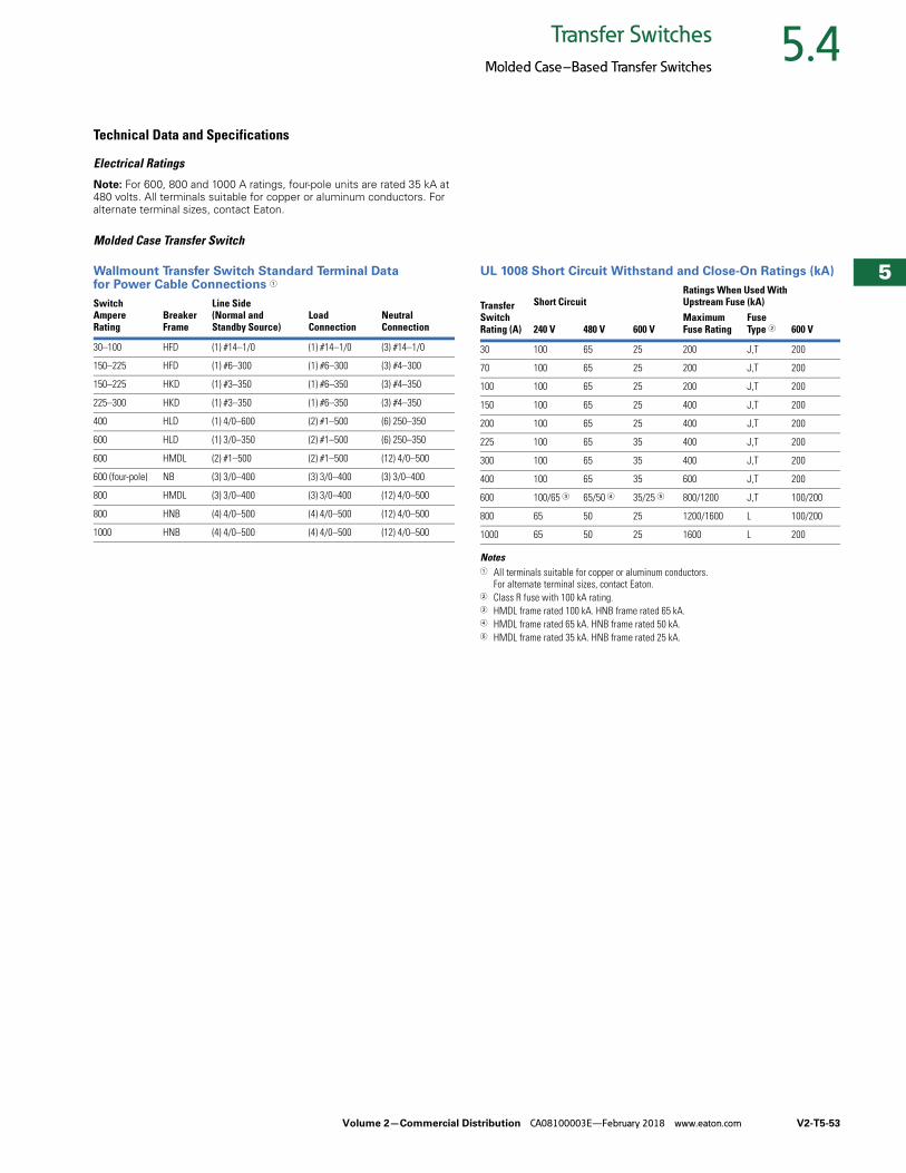
Volume 2—Commercial Distribution CA08100003E—February 2018 www.eaton.com V2-T5-53
5
5
5
5
5
5
5
5
5
5
5
5
5
5
5
5
5
5
5
5
5
5
5
5
5
5
5
5
5
5
5.4Transfer Switches
Molded Case–Based Transfer Switches
Technical Data and Specifications
Electrical Ratings
Note: For 600, 800 and 1000 A ratings, four-pole units are rated 35 kA at 480 volts. All terminals suitable for copper or aluminum conductors. For alternate terminal sizes, contact Eaton.
Molded Case Transfer Switch
Wallmount Transfer Switch Standard Terminal Data for Power Cable Connections 1
UL 1008 Short Circuit Withstand and Close-On Ratings (kA)
Notes1 All terminals suitable for copper or aluminum conductors.
For alternate terminal sizes, contact Eaton.2 Class R fuse with 100 kA rating.3 HMDL frame rated 100 kA. HNB frame rated 65 kA.4 HMDL frame rated 65 kA. HNB frame rated 50 kA.5 HMDL frame rated 35 kA. HNB frame rated 25 kA.
SwitchAmpere Rating
BreakerFrame
Line Side (Normal and Standby Source)
LoadConnection
NeutralConnection
30–100 HFD (1) #14–1/0 (1) #14–1/0 (3) #14–1/0
150–225 HFD (1) #6–300 (1) #6–300 (3) #4–300
150–225 HKD (1) #3–350 (1) #6–350 (3) #4–350
225–300 HKD (1) #3–350 (1) #6–350 (3) #4–350
400 HLD (1) 4/0–600 (2) #1–500 (6) 250–350
600 HLD (1) 3/0–350 (2) #1–500 (6) 250–350
600 HMDL (2) #1–500 (2) #1–500 (12) 4/0–500
600 (four-pole) NB (3) 3/0–400 (3) 3/0–400 (3) 3/0–400
800 HMDL (3) 3/0–400 (3) 3/0–400 (12) 4/0–500
800 HNB (4) 4/0–500 (4) 4/0–500 (12) 4/0–500
1000 HNB (4) 4/0–500 (4) 4/0–500 (12) 4/0–500
Transfer Switch Rating (A)
Short CircuitRatings When Used With Upstream Fuse (kA)
240 V 480 V 600 VMaximum Fuse Rating
Fuse Type 2 600 V
30 100 65 25 200 J,T 200
70 100 65 25 200 J,T 200
100 100 65 25 200 J,T 200
150 100 65 25 400 J,T 200
200 100 65 25 400 J,T 200
225 100 65 35 400 J,T 200
300 100 65 35 400 J,T 200
400 100 65 35 600 J,T 200
600 100/65 3 65/50 4 35/25 5 800/1200 J,T 100/200
800 65 50 25 1200/1600 L 100/200
1000 65 50 25 1600 L 200
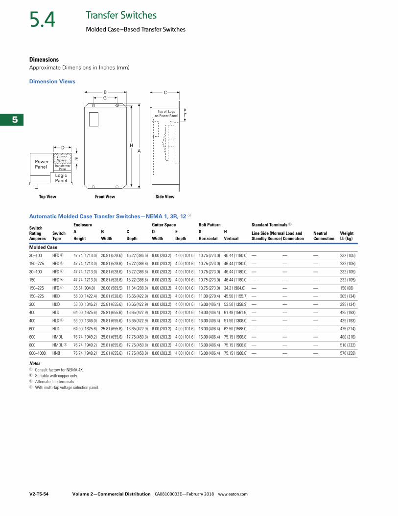
V2-T5-54 Volume 2—Commercial Distribution CA08100003E—February 2018 www.eaton.com
5
5
5
5
5
5
5
5
5
5
5
5
5
5
5
5
5
5
5
5
5
5
5
5
5
5
5
5
5
5
5.4 Transfer Switches
Molded Case–Based Transfer Switches
DimensionsApproximate Dimensions in Inches (mm)
Dimension Views
Automatic Molded Case Transfer Switches—NEMA 1, 3R, 12 1
Notes1 Consult factory for NEMA 4X.2 Suitable with copper only.3 Alternate line terminals.4 With multi-tap voltage selection panel.
SwitchRatingAmperes
SwitchType
Enclosure Gutter Space Bolt Pattern Standard Terminals 2
WeightLb (kg)
A B C D E G H Line Side (Normal Load and Standby Source) Connection
NeutralConnectionHeight Width Depth Width Depth Horizontal Vertical
Molded Case
30–100 HFD 3 47.74 (1213.0) 20.81 (528.6) 15.22 (386.6) 8.00 (203.2) 4.00 (101.6) 10.75 (273.0) 46.44 (1180.0) — — — 232 (105)
150–225 HFD 3 47.74 (1213.0) 20.81 (528.6) 15.22 (386.6) 8.00 (203.2) 4.00 (101.6) 10.75 (273.0) 46.44 (1180.0) — — — 232 (105)
30–100 HFD 4 47.74 (1213.0) 20.81 (528.6) 15.22 (386.6) 8.00 (203.2) 4.00 (101.6) 10.75 (273.0) 46.44 (1180.0) — — — 232 (105)
150 HFD 4 47.74 (1213.0) 20.81 (528.6) 15.22 (386.6) 8.00 (203.2) 4.00 (101.6) 10.75 (273.0) 46.44 (1180.0) — — — 232 (105)
150–225 HFD 3 35.61 (904.0) 20.06 (509.5) 11.34 (288.0) 8.00 (203.2) 4.00 (101.6) 10.75 (273.0) 34.31 (904.0) — — — 150 (68)
150–225 HKD 56.00 (1422.4) 20.81 (528.6) 16.65 (422.9) 8.00 (203.2) 4.00 (101.6) 11.00 (279.4) 45.50 (1155.7) — — — 305 (134)
300 HKD 53.00 (1346.2) 25.81 (655.6) 16.65 (422.9) 8.00 (203.2) 4.00 (101.6) 16.00 (406.4) 53.50 (1358.9) — — — 295 (134)
400 HLD 64.00 (1625.6) 25.81 (655.6) 16.65 (422.9) 8.00 (203.2) 4.00 (101.6) 16.00 (406.4) 61.48 (1561.6) — — — 425 (193)
400 HLD 3 53.00 (1346.0) 25.81 (655.6) 16.65 (422.9) 8.00 (203.2) 4.00 (101.6) 16.00 (406.4) 51.50 (1308.0) — — — 425 (193)
600 HLD 64.00 (1625.6) 25.81 (655.6) 16.65 (422.9) 8.00 (203.2) 4.00 (101.6) 16.00 (406.4) 62.50 (1588.0) — — — 475 (214)
600 HMDL 76.74 (1949.2) 25.81 (655.6) 17.75 (450.8) 8.00 (203.2) 4.00 (101.6) 16.00 (406.4) 75.15 (1908.8) — — — 480 (218)
800 HMDL 3 76.74 (1949.2) 25.81 (655.6) 17.75 (450.8) 8.00 (203.2) 4.00 (101.6) 16.00 (406.4) 75.15 (1908.8) — — — 510 (232)
800–1000 HNB 76.74 (1949.2) 25.81 (655.6) 17.75 (450.8) 8.00 (203.2) 4.00 (101.6) 16.00 (406.4) 75.15 (1908.8) — — — 570 (259)
LogicPanel
D
EPowerPanel Transformer
Panel
B
G
A
H
C
FTop of Lugs
on Power Panel
GutterSpace
Front View Side ViewTop View
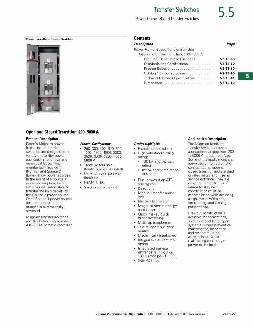
Volume 2—Commercial Distribution CA08100003E—February 2018 www.eaton.com V2-T5-55
5
5
5
5
5
5
5
5
5
5
5
5
5
5
5
5
5
5
5
5
5
5
5
5
5
5
5
5
5
5
5.5Transfer Switches
Power Frame–Based Transfer Switches
Power Frame–Based Transfer Switches ContentsDescription Page
Power Frame–Based Transfer Switches Open and Closed Transition, 200–5000 A
Features, Benefits and Functions . . . . . . . . . V2-T5-56
Standards and Certifications . . . . . . . . . . . . V2-T5-60
Product Selection . . . . . . . . . . . . . . . . . . . . . V2-T5-60
Catalog Number Selection . . . . . . . . . . . . . . V2-T5-60
Technical Data and Specifications . . . . . . . . V2-T5-61
Dimensions . . . . . . . . . . . . . . . . . . . . . . . . . V2-T5-62
Open and Closed Transition, 200–5000 AProduct DescriptionEaton’s Magnum power frame–based transfer switches are designed for a variety of standby power applications for critical and noncritical loads. They monitor both Source 1 (Normal) and Source 2 (Emergency) power sources. In the event of a Source 1 power interruption, these switches will automatically transfer the load circuits to the Source 2 power source. Once Source 1 power source has been restored, the process is automatically reversed.
Magnum transfer switches use the Eaton programmable ATC-900 automatic controller.
Product Configuration● 200, 300, 400, 600, 800,
1000, 1200, 1600, 2000, 2500, 3000, 3200, 4000, 5000 A
● Three- or four-pole (fourth pole is fully rated)
● Up to 600 Vac, 60 Hz or 50/60 Hz
● NEMA 1, 3R● Service entrance rated
Design Highlights● Freestanding enclosure● High withstand closing
ratings● 100 kA short-circuit
rating● 85 kA short-time rating
(0.5 sec)
● Dual drawout on ATS and bypass
● Deadfront● Manual transfer under
load● Electrically operated● Magnum stored energy
mechanism● Quick make / quick
break switching● Multi-tap transformer● True four-pole switched
neutral● Mechanically interlocked● Integral overcurrent trip
option● Integrated service
entrance rating option 100% rated per UL 1008
● OSHPD listed
Application DescriptionThe Magnum family of transfer switches covers applications ranging from 200 to 5000 A through 600 Vac. Some of the applications are: automatic or non-automatic configurations, open or closed transition and standard or rated suitable for use as service entrance. They are designed for applications where total system coordination must be accomplished while achieving a high level of Withstand, Interrupting, and Closing performance.
Drawout construction is available for applications, such as critical life-support systems, where preventive maintenance, inspection and testing must be accomplished while maintaining continuity of power to the load.
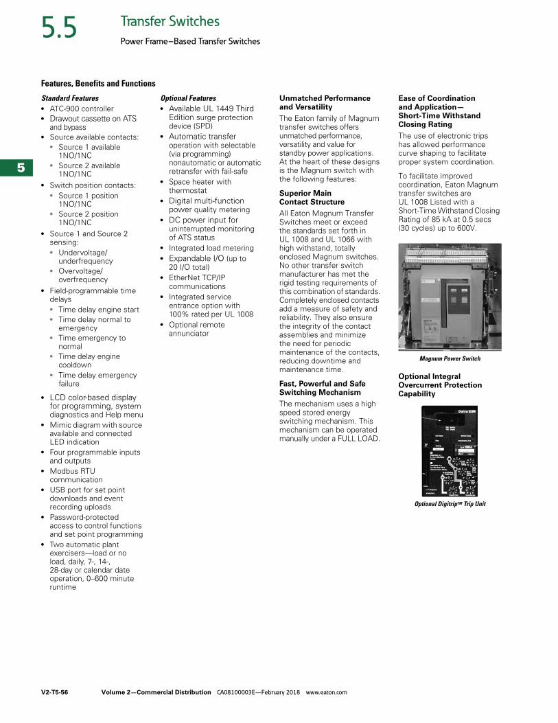
V2-T5-56 Volume 2—Commercial Distribution CA08100003E—February 2018 www.eaton.com
5
5
5
5
5
5
5
5
5
5
5
5
5
5
5
5
5
5
5
5
5
5
5
5
5
5
5
5
5
5
5.5 Transfer Switches
Power Frame–Based Transfer Switches
Features, Benefits and Functions
Standard Features● ATC-900 controller● Drawout cassette on ATS
and bypass● Source available contacts:
● Source 1 available 1NO/1NC
● Source 2 available 1NO/1NC
● Switch position contacts:● Source 1 position
1NO/1NC● Source 2 position
1NO/1NC● Source 1 and Source 2
sensing:● Undervoltage/
underfrequency● Overvoltage/
overfrequency● Field-programmable time
delays● Time delay engine start● Time delay normal to
emergency● Time emergency to
normal● Time delay engine
cooldown● Time delay emergency
failure
● LCD color-based display for programming, system diagnostics and Help menu
● Mimic diagram with source available and connected LED indication
● Four programmable inputs and outputs
● Modbus RTU communication
● USB port for set point downloads and event recording uploads
● Password-protected access to control functions and set point programming
● Two automatic plant exercisers—load or no load, daily, 7-, 14-, 28-day or calendar date operation, 0–600 minute runtime
Optional Features● Available UL 1449 Third
Edition surge protection device (SPD)
● Automatic transfer operation with selectable (via programming) nonautomatic or automatic retransfer with fail-safe
● Space heater with thermostat
● Digital multi-function power quality metering
● DC power input for uninterrupted monitoring of ATS status
● Integrated load metering● Expandable I/O (up to
20 I/O total)● EtherNet TCP/IP
communications● Integrated service
entrance option with 100% rated per UL 1008
● Optional remote annunciator
Unmatched Performance and Versatility
The Eaton family of Magnum transfer switches offers unmatched performance, versatility and value for standby power applications. At the heart of these designs is the Magnum switch with the following features:
Superior Main Contact Structure
All Eaton Magnum Transfer Switches meet or exceed the standards set forth in UL 1008 and UL 1066 with high withstand, totally enclosed Magnum switches. No other transfer switch manufacturer has met the rigid testing requirements of this combination of standards. Completely enclosed contacts add a measure of safety and reliability. They also ensure the integrity of the contact assemblies and minimize the need for periodic maintenance of the contacts, reducing downtime and maintenance time.
Fast, Powerful and Safe Switching Mechanism
The mechanism uses a high speed stored energy switching mechanism. This mechanism can be operated manually under a FULL LOAD.
Ease of Coordination and Application—Short-Time Withstand Closing Rating
The use of electronic trips has allowed performance curve shaping to facilitate proper system coordination.
To facilitate improved coordination, Eaton Magnum transfer switches are UL 1008 Listed with a Short-Time Withstand Closing Rating of 85 kA at 0.5 secs (30 cycles) up to 600V.
Magnum Power Switch
Optional Integral Overcurrent Protection Capability
Optional DigitripTM Trip Unit
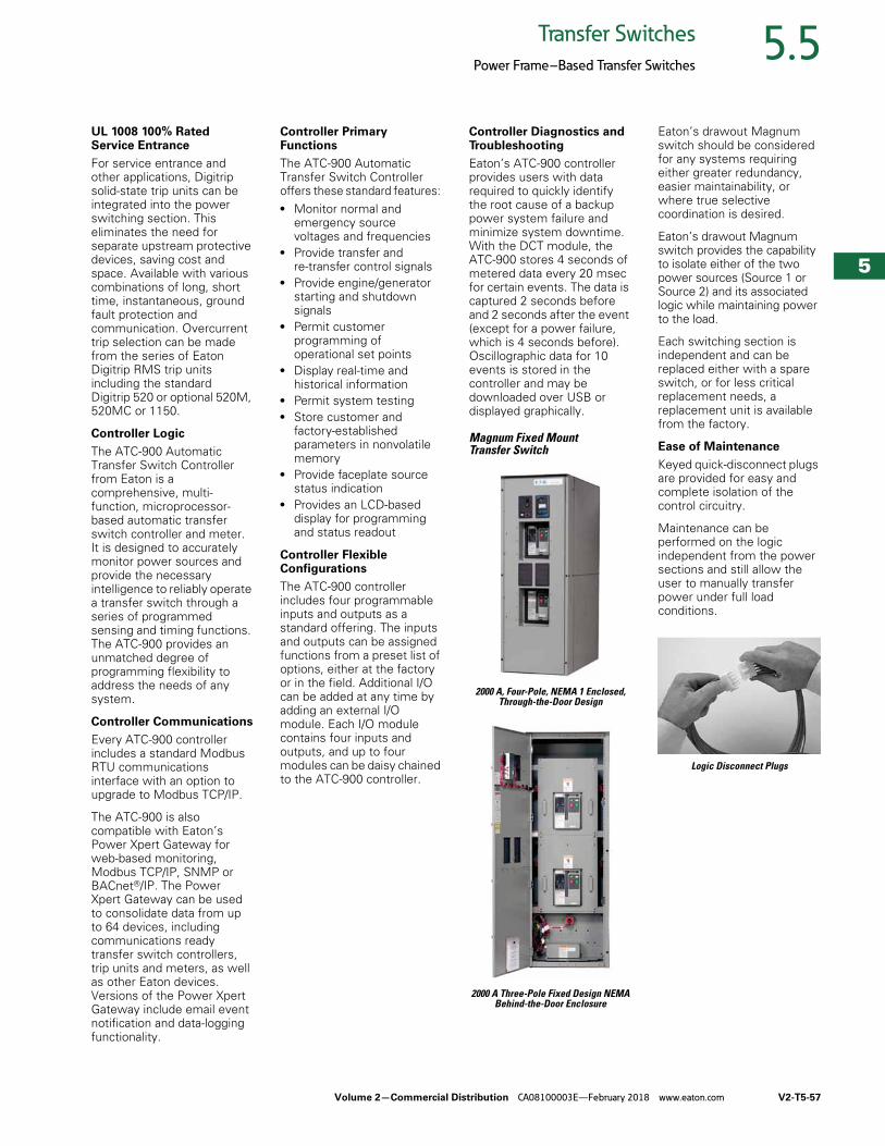
Volume 2—Commercial Distribution CA08100003E—February 2018 www.eaton.com V2-T5-57
5
5
5
5
5
5
5
5
5
5
5
5
5
5
5
5
5
5
5
5
5
5
5
5
5
5
5
5
5
5
5.5Transfer Switches
Power Frame–Based Transfer Switches
UL 1008 100% Rated Service Entrance
For service entrance and other applications, Digitrip solid-state trip units can be integrated into the power switching section. This eliminates the need for separate upstream protective devices, saving cost and space. Available with various combinations of long, short time, instantaneous, ground fault protection and communication. Overcurrent trip selection can be made from the series of Eaton Digitrip RMS trip units including the standard Digitrip 520 or optional 520M, 520MC or 1150.
Controller Logic
The ATC-900 Automatic Transfer Switch Controller from Eaton is a comprehensive, multi-function, microprocessor-based automatic transfer switch controller and meter. It is designed to accurately monitor power sources and provide the necessary intelligence to reliably operate a transfer switch through a series of programmed sensing and timing functions. The ATC-900 provides an unmatched degree of programming flexibility to address the needs of any system.
Controller Communications
Every ATC-900 controller includes a standard Modbus RTU communications interface with an option to upgrade to Modbus TCP/IP.
The ATC-900 is also compatible with Eaton’s Power Xpert Gateway for web-based monitoring, Modbus TCP/IP, SNMP or BACnet®/IP. The Power Xpert Gateway can be used to consolidate data from up to 64 devices, including communications ready transfer switch controllers, trip units and meters, as well as other Eaton devices. Versions of the Power Xpert Gateway include email event notification and data-logging functionality.
Controller Primary Functions
The ATC-900 Automatic Transfer Switch Controller offers these standard features: ● Monitor normal and
emergency source voltages and frequencies
● Provide transfer and re-transfer control signals
● Provide engine/generator starting and shutdown signals
● Permit customer programming of operational set points
● Display real-time and historical information
● Permit system testing ● Store customer and
factory-established parameters in nonvolatile memory
● Provide faceplate source status indication
● Provides an LCD-based display for programming and status readout
Controller Flexible Configurations
The ATC-900 controller includes four programmable inputs and outputs as a standard offering. The inputs and outputs can be assigned functions from a preset list of options, either at the factory or in the field. Additional I/O can be added at any time by adding an external I/O module. Each I/O module contains four inputs and outputs, and up to four modules can be daisy chained to the ATC-900 controller.
Controller Diagnostics and Troubleshooting
Eaton’s ATC-900 controller provides users with data required to quickly identify the root cause of a backup power system failure and minimize system downtime. With the DCT module, the ATC-900 stores 4 seconds of metered data every 20 msec for certain events. The data is captured 2 seconds before and 2 seconds after the event (except for a power failure, which is 4 seconds before). Oscillographic data for 10 events is stored in the controller and may be downloaded over USB or displayed graphically.
Magnum Fixed Mount Transfer Switch
2000 A, Four-Pole, NEMA 1 Enclosed, Through-the-Door Design
2000 A Three-Pole Fixed Design NEMA Behind-the-Door Enclosure
Eaton’s drawout Magnum switch should be considered for any systems requiring either greater redundancy, easier maintainability, or where true selective coordination is desired.
Eaton’s drawout Magnum switch provides the capability to isolate either of the two power sources (Source 1 or Source 2) and its associated logic while maintaining power to the load.
Each switching section is independent and can be replaced either with a spare switch, or for less critical replacement needs, a replacement unit is available from the factory.
Ease of Maintenance
Keyed quick-disconnect plugs are provided for easy and complete isolation of the control circuitry.
Maintenance can be performed on the logic independent from the power sections and still allow the user to manually transfer power under full load conditions.
Logic Disconnect Plugs
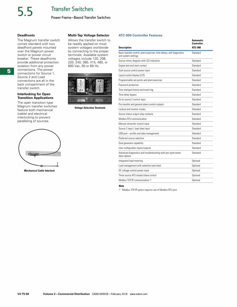
V2-T5-58 Volume 2—Commercial Distribution CA08100003E—February 2018 www.eaton.com
5
5
5
5
5
5
5
5
5
5
5
5
5
5
5
5
5
5
5
5
5
5
5
5
5
5
5
5
5
5
5.5 Transfer Switches
Power Frame–Based Transfer Switches
Deadfronts
The Magnum transfer switch comes standard with two deadfront panels mounted over the Magnum power switch or power circuit breaker. These deadfronts provide additional protection isolation from any power connections. The power connections for Source 1, Source 2 and Load connections are all in the back compartment of the transfer switch.
Interlocking for Open Transition Applications
The open transition type Magnum transfer switches feature both mechanical (cable) and electrical interlocking to prevent paralleling of sources.
Mechanical Cable Interlock
Multi-Tap Voltage Selector
Allows the transfer switch to be readily applied on most system voltages worldwide by connecting to the proper terminals. Available system voltages include 120, 208, 220, 240, 380, 415, 480, or 600 Vac, 50 or 60 Hz.
Voltage Selection Terminals
ATC-900 Controller Features
Note1 Modbus TCP/IP option requires use of Modbus RTU port.
Automatic Controller
Description ATC-900
Basic transfer control, plant exerciser, time delays, self diagnostics and system settings
Standard
Source mimic diagram with LED indication Standard
Engine test and start contact Standard
Dual source control power input Standard
Liquid crystal display (LCD) Standard
Programmable set points and plant exerciser Standard
Password protection Standard
Time stamped history and event log Standard
Time delay bypass Standard
Go to source 2 control input Standard
Pre-transfer and general alarm control outputs Standard
Lockout and monitor modes Standard
Source status output relay contacts Standard
Modbus RTU communication Standard
Manual retransfer control input Standard
Source 2 input / load shed input Standard
USB port—profile and data management Standard
Preferred source selection Standard
Dual generator capability Standard
User configurable inputs/outputs Standard
Advanced diagnostics and troubleshooting with pre-/post-event data capture
Standard
Integrated load metering Optional
Load management with selective load shed Optional
DC voltage control power input Optional
Three source ATS master/slave control Optional
Modbus TCP/IP communication 1 Optional
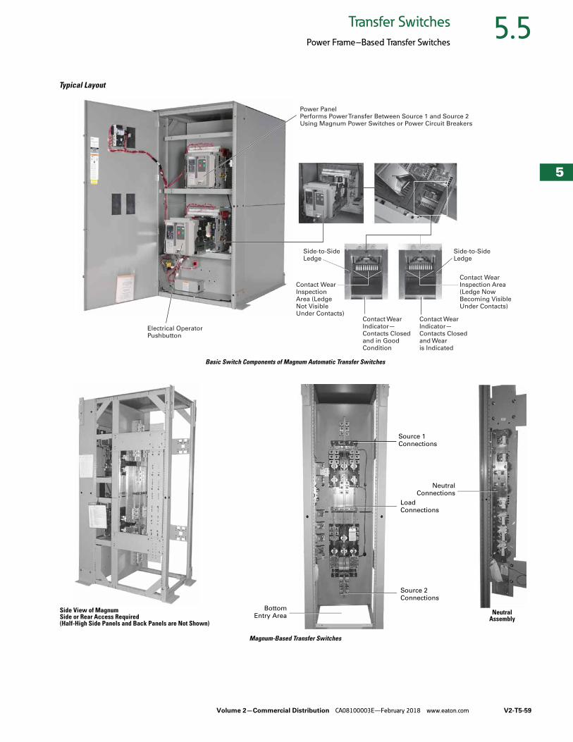
Volume 2—Commercial Distribution CA08100003E—February 2018 www.eaton.com V2-T5-59
5
5
5
5
5
5
5
5
5
5
5
5
5
5
5
5
5
5
5
5
5
5
5
5
5
5
5
5
5
5
5.5Transfer Switches
Power Frame–Based Transfer Switches
Typical Layout
Basic Switch Components of Magnum Automatic Transfer Switches
Magnum-Based Transfer Switches
Power PanelPerforms Power Transfer Between Source 1 and Source 2 Using Magnum Power Switches or Power Circuit Breakers
Electrical Operator Pushbutton
Side-to-SideLedge
Side-to-SideLedge
Contact WearIndicator—Contacts Closedand in GoodCondition
Contact WearIndicator—Contacts Closedand Wearis Indicated
Contact Wear Inspection Area (Ledge Not Visible Under Contacts)
Contact Wear Inspection Area (Ledge Now Becoming Visible Under Contacts)
BottomEntry Area
Side View of MagnumSide or Rear Access Required(Half-High Side Panels and Back Panels are Not Shown)
Source 2 Connections
Load
Connections
Source 1
Connections
NeutralConnections
Neutral Assembly
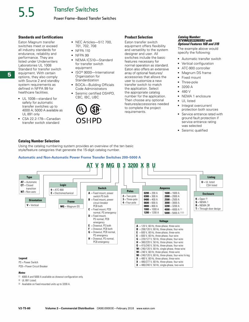
V2-T5-60 Volume 2—Commercial Distribution CA08100003E—February 2018 www.eaton.com
5
5
5
5
5
5
5
5
5
5
5
5
5
5
5
5
5
5
5
5
5
5
5
5
5
5
5
5
5
5
5.5 Transfer Switches
Power Frame–Based Transfer Switches
Standards and CertificationsEaton Magnum transfer switches meet or exceed all industry standards for endurance, reliability and performance. They are listed under Underwriters Laboratories UL 1008 Standard for transfer switch equipment. With certain options, they also comply with Source 2 and standby system requirements as defined in NFPA 99 for healthcare facilities.
● UL 1008—standard for safety for automatic transfer switches up to 4000 A; 5000 A available as UL 891 only
● CSA 22.2-178—Canadian transfer switch standard
● NEC Articles—517, 700, 701, 702, 708
● NFPA 110● NFPA 99● NEMA ICS10—Standard
for transfer switch equipment
● ISO® 9000—International Organization for Standardization
● BOCA—Building Officials Code Administrators
● Seismic certified OSHPD, CBC, IBC, UBC
Product SelectionEaton transfer switch equipment offers flexibility and versatility to the system designer and user. All switches include the basic features necessary for normal operation as standard. Eaton also offers an extensive array of optional features/accessories that allows the user to customize a new transfer switch to match the application. Select the appropriate catalog number for the application. Then choose any optional features/accessories needed to complete the project requirements.
Catalog Number: ATV9MGB33200XRU with Optional Features 16B and 37BThe example above would specify the following:
● Automatic transfer switch● Vertical configuration● ATC-900 controller● Magnum DS frame● Fixed mount● Three-pole● 3200 A● 480 V● NEMA 1 enclosure● UL listed● Integral overcurrent
protection both sources● Service entrance rated with
ground fault protection if service entrance rating was selected
● Seismic qualified
Catalog Number SelectionUsing the catalog numbering system provides an overview of the ten basic style/feature categories that generate the 15-digit catalog number.
Automatic and Non-Automatic Power Frame Transfer Switches 200–5000 A
Notes1 4000 A and 5000 A available as drawout configuration only.2 UL 891 Listed.3 Available on fixed-mounted units up to 3200 A.
Logic
9 = ATC-900 E = Electromechanical
Type
AT = AutomaticCT = Closed
transitionNT = Non-auto
Orientation
V = Vertical
Poles
2 = Two-pole3 = Three-pole4 = Four-pole
Amperes
0200 = 200 A0300 = 300 A0400 = 400 A0600 = 600 A0800 = 800 A1000 = 1000 A1200 = 1200 A
1600 = 1600 A2000 = 2000 A2500 = 2500 A3000 = 3000 A3200 = 3200 A4000 = 4000 A 15000 = 5000 A 12
Enclosure
K = Open 3S = NEMA 1R = NEMA 3RT = Through-door design
Listing
U = UL listedCSA listed
Frame
MG = Magnum DS
Switch
A = Fixed mount, power switch PS both
B = Fixed mount, power circuit breakerPCB both
C = Fixed mount, PCB normal, PS emergency
D = Fixed mount, PS normal, PCB emergency
E = Drawout, PS bothF = Drawout, PCB bothG = Drawout, PCB normal,
PS emergencyH = Drawout, PS normal,
PCB emergency
Legend:PS = Power SwitchPCB = Power Circuit Breaker
Voltage
A = 120 V, 60 Hz, three-phase, three-wireB = 208/120 V, 60 Hz, three-phase, four-wireE = 600 V, 60 Hz, three-phase, three-wireE = 600 V, 60 Hz, three-phase, four-wireG = 220/127 V, 50 Hz, three-phase, four-wireH = 380/220 V, 50 Hz, three-phase, four-wireO = 415/240 V, 50 Hz, three-phase, four-wireW = 240/120 V, 60 Hz, single-phase, three-wireW = 240 V, 60 Hz, three-phase, three-wireW = 240/120 V, 60 Hz, three-phase, four-wire hi-legX = 480 V, 60 Hz, three-phase, three-wireX = 480/277 V, 60 Hz, three-phase, four-wireX = 480/240 V, 50 Hz, single-phase, two-wire
AT V 9 MG B 3 3200 X R U
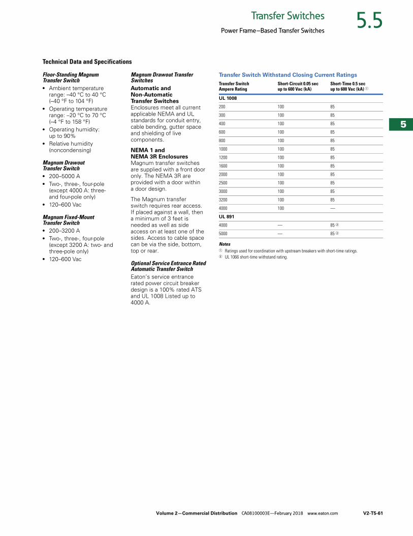
Volume 2—Commercial Distribution CA08100003E—February 2018 www.eaton.com V2-T5-61
5
5
5
5
5
5
5
5
5
5
5
5
5
5
5
5
5
5
5
5
5
5
5
5
5
5
5
5
5
5
5.5Transfer Switches
Power Frame–Based Transfer Switches
Technical Data and Specifications
Floor-Standing Magnum Transfer Switch● Ambient temperature
range: –40 °C to 40 °C (–40 °F to 104 °F)
● Operating temperature range: –20 °C to 70 °C (–4 °F to 158 °F)
● Operating humidity: up to 90%
● Relative humidity(noncondensing)
Magnum Drawout Transfer Switch● 200–5000 A● Two-, three-, four-pole
(except 4000 A: three- and four-pole only)
● 120–600 Vac
Magnum Fixed-Mount Transfer Switch● 200–3200 A● Two-, three-, four-pole
(except 3200 A: two- and three-pole only)
● 120–600 Vac
Magnum Drawout Transfer SwitchesAutomatic and Non-Automatic Transfer SwitchesEnclosures meet all current applicable NEMA and UL standards for conduit entry, cable bending, gutter space and shielding of live components.
NEMA 1 and NEMA 3R EnclosuresMagnum transfer switches are supplied with a front door only. The NEMA 3R are provided with a door within a door design.
The Magnum transfer switch requires rear access. If placed against a wall, then a minimum of 3 feet is needed as well as side access on at least one of the sides. Access to cable space can be via the side, bottom, top or rear.
Optional Service Entrance Rated Automatic Transfer SwitchEaton’s service entrance rated power circuit breaker design is a 100% rated ATS and UL 1008 Listed up to 4000 A.
Transfer Switch Withstand Closing Current Ratings
Notes1 Ratings used for coordination with upstream breakers with short-time ratings.2 UL 1066 short-time withstand rating.
Transfer Switch Ampere Rating
Short-Circuit 0.05 secup to 600 Vac (kA)
Short-Time 0.5 secup to 600 Vac (kA) 1
UL 1008
200 100 85
300 100 85
400 100 85
600 100 85
800 100 85
1000 100 85
1200 100 85
1600 100 85
2000 100 85
2500 100 85
3000 100 85
3200 100 85
4000 100 —
UL 891
4000 — 85 2
5000 — 85 2
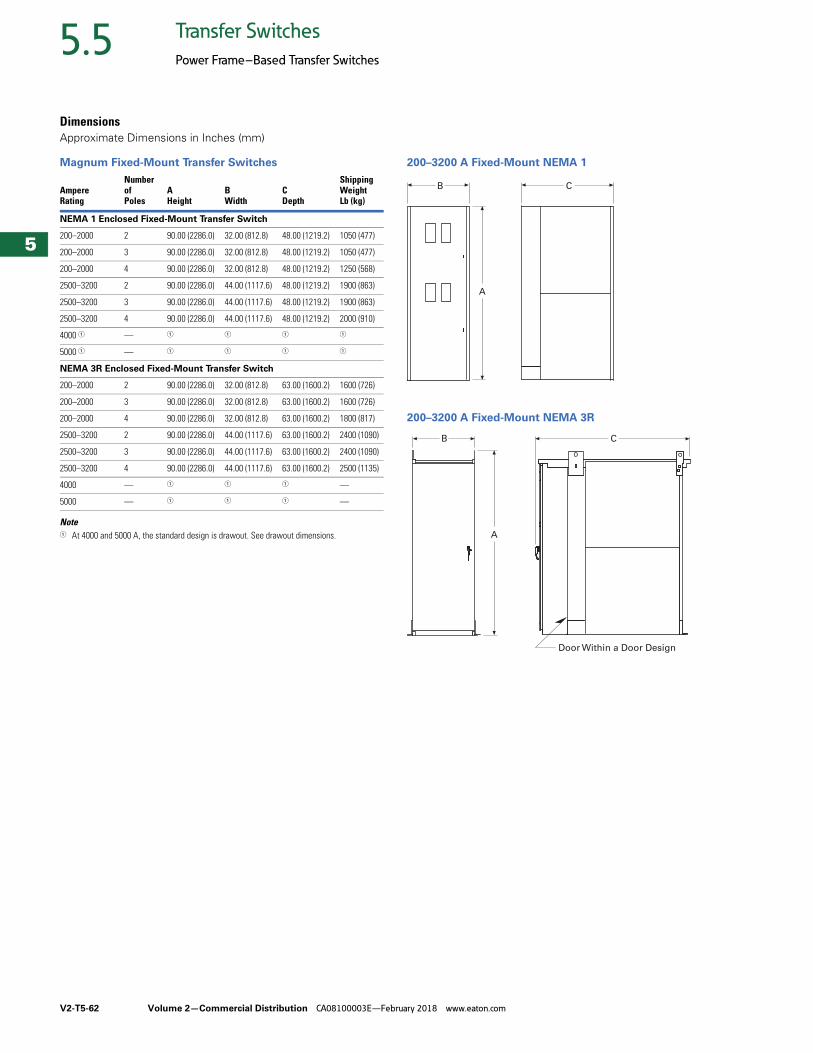
V2-T5-62 Volume 2—Commercial Distribution CA08100003E—February 2018 www.eaton.com
5
5
5
5
5
5
5
5
5
5
5
5
5
5
5
5
5
5
5
5
5
5
5
5
5
5
5
5
5
5
5.5 Transfer Switches
Power Frame–Based Transfer Switches
Dimensions Approximate Dimensions in Inches (mm)
Magnum Fixed-Mount Transfer Switches
Note1 At 4000 and 5000 A, the standard design is drawout. See drawout dimensions.
200–3200 A Fixed-Mount NEMA 1
200–3200 A Fixed-Mount NEMA 3R
AmpereRating
Numberof Poles
AHeight
BWidth
CDepth
ShippingWeight Lb (kg)
NEMA 1 Enclosed Fixed-Mount Transfer Switch
200–2000 2 90.00 (2286.0) 32.00 (812.8) 48.00 (1219.2) 1050 (477)
200–2000 3 90.00 (2286.0) 32.00 (812.8) 48.00 (1219.2) 1050 (477)
200–2000 4 90.00 (2286.0) 32.00 (812.8) 48.00 (1219.2) 1250 (568)
2500–3200 2 90.00 (2286.0) 44.00 (1117.6) 48.00 (1219.2) 1900 (863)
2500–3200 3 90.00 (2286.0) 44.00 (1117.6) 48.00 (1219.2) 1900 (863)
2500–3200 4 90.00 (2286.0) 44.00 (1117.6) 48.00 (1219.2) 2000 (910)
4000 1 — 1 1 1 1
5000 1 — 1 1 1 1
NEMA 3R Enclosed Fixed-Mount Transfer Switch
200–2000 2 90.00 (2286.0) 32.00 (812.8) 63.00 (1600.2) 1600 (726)
200–2000 3 90.00 (2286.0) 32.00 (812.8) 63.00 (1600.2) 1600 (726)
200–2000 4 90.00 (2286.0) 32.00 (812.8) 63.00 (1600.2) 1800 (817)
2500–3200 2 90.00 (2286.0) 44.00 (1117.6) 63.00 (1600.2) 2400 (1090)
2500–3200 3 90.00 (2286.0) 44.00 (1117.6) 63.00 (1600.2) 2400 (1090)
2500–3200 4 90.00 (2286.0) 44.00 (1117.6) 63.00 (1600.2) 2500 (1135)
4000 — 1 1 1 —
5000 — 1 1 1 —
A
B C
A
B C
Door Within a Door DesignD
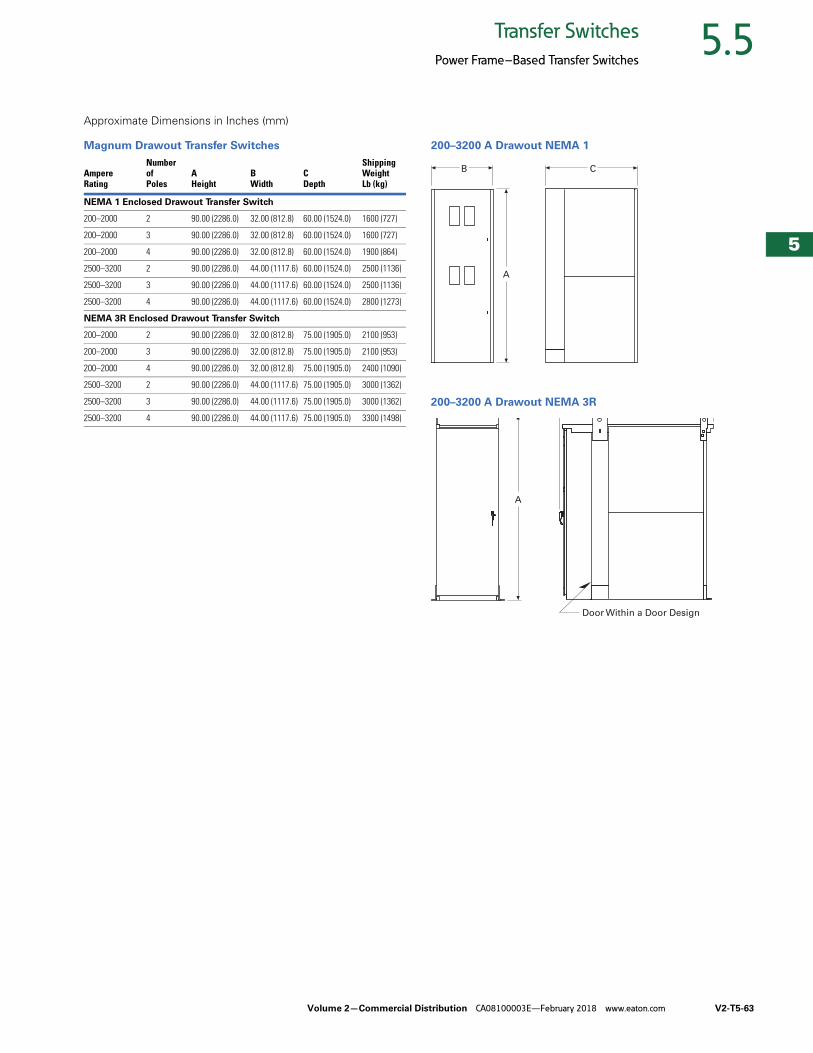
Volume 2—Commercial Distribution CA08100003E—February 2018 www.eaton.com V2-T5-63
5
5
5
5
5
5
5
5
5
5
5
5
5
5
5
5
5
5
5
5
5
5
5
5
5
5
5
5
5
5
5.5Transfer Switches
Power Frame–Based Transfer Switches
Approximate Dimensions in Inches (mm)
Magnum Drawout Transfer Switches 200–3200 A Drawout NEMA 1
200–3200 A Drawout NEMA 3R
AmpereRating
Numberof Poles
AHeight
BWidth
CDepth
ShippingWeight Lb (kg)
NEMA 1 Enclosed Drawout Transfer Switch
200–2000 2 90.00 (2286.0) 32.00 (812.8) 60.00 (1524.0) 1600 (727)
200–2000 3 90.00 (2286.0) 32.00 (812.8) 60.00 (1524.0) 1600 (727)
200–2000 4 90.00 (2286.0) 32.00 (812.8) 60.00 (1524.0) 1900 (864)
2500–3200 2 90.00 (2286.0) 44.00 (1117.6) 60.00 (1524.0) 2500 (1136)
2500–3200 3 90.00 (2286.0) 44.00 (1117.6) 60.00 (1524.0) 2500 (1136)
2500–3200 4 90.00 (2286.0) 44.00 (1117.6) 60.00 (1524.0) 2800 (1273)
NEMA 3R Enclosed Drawout Transfer Switch
200–2000 2 90.00 (2286.0) 32.00 (812.8) 75.00 (1905.0) 2100 (953)
200–2000 3 90.00 (2286.0) 32.00 (812.8) 75.00 (1905.0) 2100 (953)
200–2000 4 90.00 (2286.0) 32.00 (812.8) 75.00 (1905.0) 2400 (1090)
2500–3200 2 90.00 (2286.0) 44.00 (1117.6) 75.00 (1905.0) 3000 (1362)
2500–3200 3 90.00 (2286.0) 44.00 (1117.6) 75.00 (1905.0) 3000 (1362)
2500–3200 4 90.00 (2286.0) 44.00 (1117.6) 75.00 (1905.0) 3300 (1498)
A
B C
A
Door Within a Door DesignD
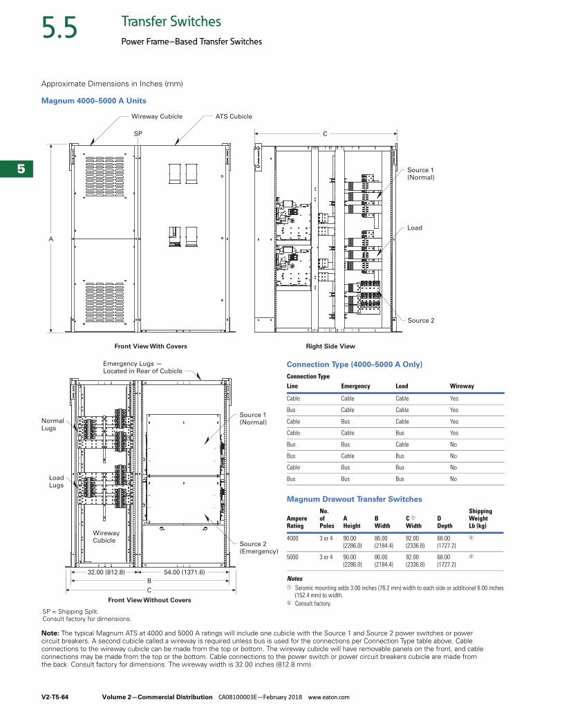
V2-T5-64 Volume 2—Commercial Distribution CA08100003E—February 2018 www.eaton.com
5
5
5
5
5
5
5
5
5
5
5
5
5
5
5
5
5
5
5
5
5
5
5
5
5
5
5
5
5
5
5.5 Transfer Switches
Power Frame–Based Transfer Switches
Approximate Dimensions in Inches (mm)
Magnum 4000–5000 A Units
Note: The typical Magnum ATS at 4000 and 5000 A ratings will include one cubicle with the Source 1 and Source 2 power switches or power circuit breakers. A second cubicle called a wireway is required unless bus is used for the connections per Connection Type table above. Cable connections to the wireway cubicle can be made from the top or bottom. The wireway cubicle will have removable panels on the front, and cable connections may be made from the top or the bottom. Cable connections to the power switch or power circuit breakers cubicle are made from the back. Consult factory for dimensions. The wireway width is 32.00 inches (812.8 mm).
Front View With Covers
C
Front View Without Covers
Right Side View
A
Wireway Cubicle ATS Cubicle
Source 1(Normal)
Source 2(Emergency)
SP
Emergency Lugs — Located in Rear of Cubicle
NormalLugs
LoadLugs
WirewayCubicle
Source 1(Normal)
Load
Source 2
BC
32.00 (812.8) 54.00 (1371.6)
SP = Shipping Split.Consult factory for dimensions.
Connection Type (4000–5000 A Only)
Magnum Drawout Transfer Switches
Notes1 Seismic mounting adds 3.00 inches (76.2 mm) width to each side or additional 6.00 inches
(152.4 mm) to width.2 Consult factory.
Connection TypeWirewayLine Emergency Load
Cable Cable Cable Yes
Bus Cable Cable Yes
Cable Bus Cable Yes
Cable Cable Bus Yes
Bus Bus Cable No
Bus Cable Bus No
Cable Bus Bus No
Bus Bus Bus No
AmpereRating
No.of Poles
AHeight
BWidth
C 1Width
DDepth
ShippingWeight Lb (kg)
4000 3 or 4 90.00(2286.0)
86.00(2184.4)
92.00(2336.8)
68.00(1727.2)
2
5000 3 or 4 90.00(2286.0)
86.00(2184.4)
92.00(2336.8)
68.00(1727.2)
2

Volume 2—Commercial Distribution CA08100003E—February 2018 www.eaton.com V2-T5-65
5
5
5
5
5
5
5
5
5
5
5
5
5
5
5
5
5
5
5
5
5
5
5
5
5
5
5
5
5
5
5.6Transfer Switches
Bypass Isolation Power Frame–Based Transfer Switches
Bypass Isolation Power Frame–Based Transfer Switches ContentsDescription Page
Bypass Isolation Power Frame–Based Transfer Switches Open and Closed Transition, 200–5000 A
Standards and Certifications . . . . . . . . . . . . V2-T5-67
Catalog Number Selection . . . . . . . . . . . . . . V2-T5-67
Product Selection . . . . . . . . . . . . . . . . . . . . . V2-T5-68
Technical Data and Specifications . . . . . . . . V2-T5-68
Dimensions . . . . . . . . . . . . . . . . . . . . . . . . . V2-T5-69
Open and Closed Transition, 200–5000 AProduct DescriptionEaton’s bypass isolation transfer switch is used in life safety and other mission-critical applications where redundancy is desired and maintenance of the automatic transfer switch can be performed without interrupting power to the load. Transfer switches are equipped with the ATC-900 controller.
Product Configuration● 200, 300, 400, 600, 800,
1000, 1200, 1600, 2000, 2500, 3000, 3200, 4000 and 5000 A
● Three- or four-pole (fourth pole is fully rated)
● Up to 600 Vac, 60 Hz or 50/60 Hz
● NEMA 1, 3R● Service entrance rated
Design Highlights● High withstand ratings● 100 kA short-circuit rating
(0.05 sec, up to 600 Vac)● 85 kA short-time rating
(0.5 sec, up to 600 Vac)● Dual drawout—ATS and
bypass● Deadfront● Manual transfer under load● Electrically operated● Magnum stored energy
mechanism● Quick make / quick break
switching● Multi-tap transformer● Fully rated fourth-pole
(switched neutral)● Mechanically interlocked● Integral overcurrent trip
option● Integrated service
entrance rating option
FeaturesStandard Features● ATC-900 controller● Drawout cassette on ATS
and bypass● Source available contacts:
● Source 1 available 1NO/1NC
● Source 2 available 1NO/1NC
● Switch position contacts:● Source 1 position
1NO/1NC● Source 2 position
1NO/1NC● Source 1 and Source 2
sensing:● Undervoltage/
underfrequency● Overvoltage/
overfrequency ● Field-programmable
time delays● Time delay engine start● Time delay normal to
emergency● Time emergency to normal ● Time delay engine cooldown● Time delay emergency
failure● LCD color-based display for
programming, system diagnostics and Help menu
● Mimic diagram with source available and connected LED indication
● Four programmable inputs and outputs
● Standard Modbus 485● Password-protected
access to control functions and set point programming
● Two automatic plant exercisers—load or no load, daily, 7, 14, 28 or calendar date operation, 0–600 minute runtime
Optional Features● Available UL 1449 Third
Edition surge protection device (SPD)
● Automatic transfer operation with selectable (via programming) nonautomatic or automatic retransfer with fail-safe
● Space heater with thermostat
● Digital multi-function power quality metering
● DC power input for uninterrupted monitoring of ATS status
● Integrated load metering ● Expandable I/O (up to 20
I/O total)● Ethernet TCP/IP
communications
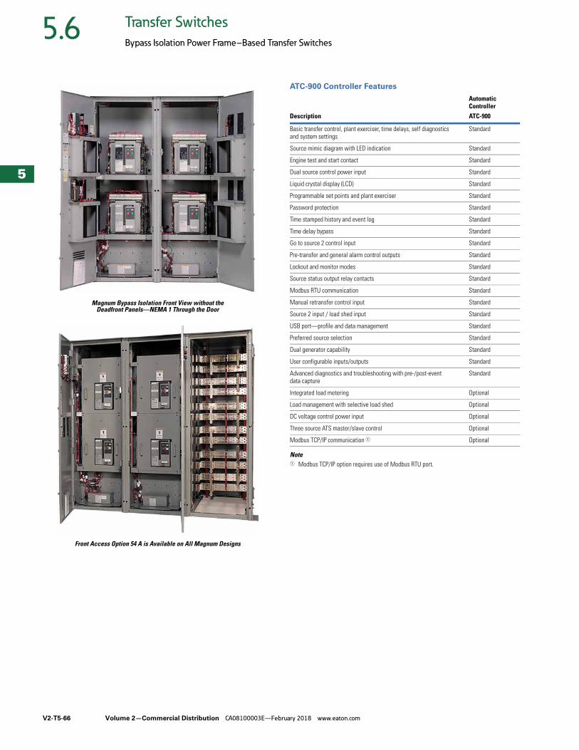
V2-T5-66 Volume 2—Commercial Distribution CA08100003E—February 2018 www.eaton.com
5
5
5
5
5
5
5
5
5
5
5
5
5
5
5
5
5
5
5
5
5
5
5
5
5
5
5
5
5
5
5.6 Transfer Switches
Bypass Isolation Power Frame–Based Transfer Switches
Magnum Bypass Isolation Front View without theDeadfront Panels—NEMA 1 Through the Door
Front Access Option 54 A is Available on All Magnum Designs
ATC-900 Controller Features
Note1 Modbus TCP/IP option requires use of Modbus RTU port.
Automatic Controller
Description ATC-900
Basic transfer control, plant exerciser, time delays, self diagnostics and system settings
Standard
Source mimic diagram with LED indication Standard
Engine test and start contact Standard
Dual source control power input Standard
Liquid crystal display (LCD) Standard
Programmable set points and plant exerciser Standard
Password protection Standard
Time stamped history and event log Standard
Time delay bypass Standard
Go to source 2 control input Standard
Pre-transfer and general alarm control outputs Standard
Lockout and monitor modes Standard
Source status output relay contacts Standard
Modbus RTU communication Standard
Manual retransfer control input Standard
Source 2 input / load shed input Standard
USB port—profile and data management Standard
Preferred source selection Standard
Dual generator capability Standard
User configurable inputs/outputs Standard
Advanced diagnostics and troubleshooting with pre-/post-event data capture
Standard
Integrated load metering Optional
Load management with selective load shed Optional
DC voltage control power input Optional
Three source ATS master/slave control Optional
Modbus TCP/IP communication 1 Optional
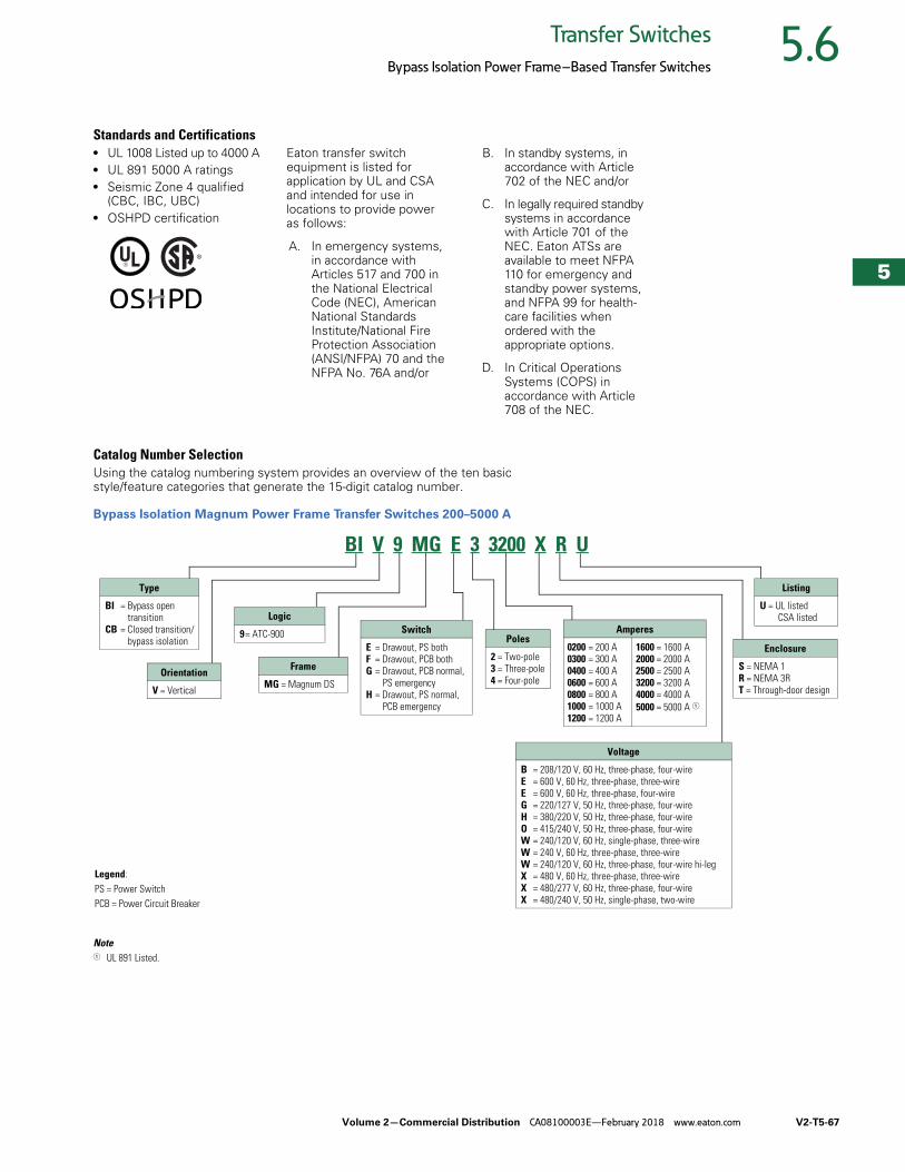
Volume 2—Commercial Distribution CA08100003E—February 2018 www.eaton.com V2-T5-67
5
5
5
5
5
5
5
5
5
5
5
5
5
5
5
5
5
5
5
5
5
5
5
5
5
5
5
5
5
5
5.6Transfer Switches
Bypass Isolation Power Frame–Based Transfer Switches
Standards and Certifications● UL 1008 Listed up to 4000 A● UL 891 5000 A ratings● Seismic Zone 4 qualified
(CBC, IBC, UBC)● OSHPD certification
Eaton transfer switch equipment is listed for application by UL and CSA and intended for use in locations to provide power as follows:
A. In emergency systems, in accordance with Articles 517 and 700 in the National Electrical Code (NEC), American National Standards Institute/National Fire Protection Association (ANSI/NFPA) 70 and the NFPA No. 76A and/or
B. In standby systems, in accordance with Article 702 of the NEC and/or
C. In legally required standby systems in accordance with Article 701 of the NEC. Eaton ATSs are available to meet NFPA 110 for emergency and standby power systems, and NFPA 99 for health-care facilities when ordered with the appropriate options.
D. In Critical Operations Systems (COPS) in accordance with Article 708 of the NEC.
Catalog Number SelectionUsing the catalog numbering system provides an overview of the ten basic style/feature categories that generate the 15-digit catalog number.
Bypass Isolation Magnum Power Frame Transfer Switches 200–5000 A
Note1 UL 891 Listed.
Logic
9= ATC-900
Type
BI = Bypass open transition
CB = Closed transition/bypass isolation
Orientation
V = Vertical
Poles
2 = Two-pole3 = Three-pole4 = Four-pole
Amperes
0200 = 200 A0300 = 300 A0400 = 400 A0600 = 600 A0800 = 800 A1000 = 1000 A1200 = 1200 A
1600 = 1600 A2000 = 2000 A2500 = 2500 A3200 = 3200 A4000 = 4000 A5000 = 5000 A 1
Enclosure
S = NEMA 1R = NEMA 3RT = Through-door design
Listing
U = UL listedCSA listed
Frame
MG = Magnum DS
Switch
E = Drawout, PS bothF = Drawout, PCB bothG = Drawout, PCB normal,
PS emergencyH = Drawout, PS normal,
PCB emergency
Legend:PS = Power SwitchPCB = Power Circuit Breaker
Voltage
B = 208/120 V, 60 Hz, three-phase, four-wireE = 600 V, 60 Hz, three-phase, three-wireE = 600 V, 60 Hz, three-phase, four-wireG = 220/127 V, 50 Hz, three-phase, four-wireH = 380/220 V, 50 Hz, three-phase, four-wireO = 415/240 V, 50 Hz, three-phase, four-wireW = 240/120 V, 60 Hz, single-phase, three-wireW = 240 V, 60 Hz, three-phase, three-wireW = 240/120 V, 60 Hz, three-phase, four-wire hi-legX = 480 V, 60 Hz, three-phase, three-wireX = 480/277 V, 60 Hz, three-phase, four-wireX = 480/240 V, 50 Hz, single-phase, two-wire
BI V 9 MG E 3 3200 X R U

V2-T5-68 Volume 2—Commercial Distribution CA08100003E—February 2018 www.eaton.com
5
5
5
5
5
5
5
5
5
5
5
5
5
5
5
5
5
5
5
5
5
5
5
5
5
5
5
5
5
5
5.6 Transfer Switches
Bypass Isolation Power Frame–Based Transfer Switches
Product SelectionEaton transfer switch equipment offers flexibility and versatility to the system designer and user. All switches include the basic features necessary for normal operation as standard. Eaton also offers an extensive array of optional features/accessories that allows the user to customize a new transfer switch to match the application. Select the appropriate catalog number for the application. Then choose any optional features/accessories needed to complete the project requirements.
Catalog Number: BIV9MGE33200XRU The example above would specify the following:
● Bypass isolation● Vertical configuration● ATC-900 controller● Magnum DS frame● Power switch normal
and emergency● Drawout● Three-pole● 3200 A● 480 V● NEMA 3R enclosure● UL listed
Technical Data and Specifications
Typical Bypass Isolation Switch Schematic
Transfer Switch Withstand Closing Current Ratings
Notes1 Ratings used for coordination with upstream breakers with short-time ratings.2 UL 1066 short-time withstand rating.
Transfer Switch Ampere Rating
Short-Circuit 0.05 secup to 600 Vac (kA)
Short-Time 0.5 secup to 600 Vac (kA) 1
UL 1008
200 100 85
300 100 85
400 100 85
600 100 85
800 100 85
1000 100 85
1200 100 85
1600 100 85
2000 100 85
2500 100 85
3000 100 85
3200 100 85
4000 100 —
UL 891
4000 — 85 2
5000 — 85 2
SOURCE 1
SOURCE 1SOURCE 1
SOURCE 1
BYPASS
SOURCE 1
SOURCE 1
SOURCE 1
AVAILABLE
SOURCE 2
ISOLATED
ISOLATED
POSITION
SOURCE 2POSITION
SOURCE 2
AVAILABLE
SOURCE 2SOURCE 2
SOURCE 2INCOMING
ATS
BYPASS
BYPASSATS
LOAD
SOURCE 2
BYPASS
INCOMING
A
A
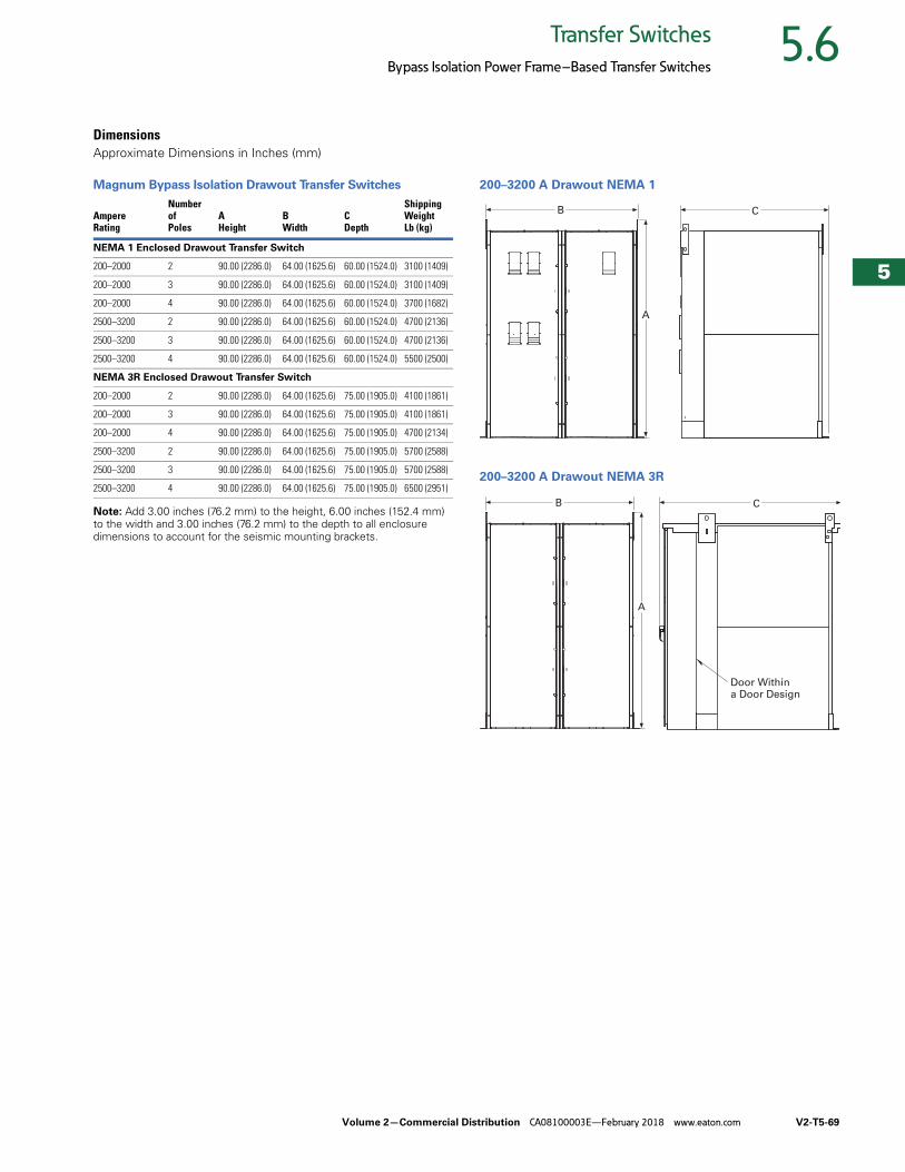
Volume 2—Commercial Distribution CA08100003E—February 2018 www.eaton.com V2-T5-69
5
5
5
5
5
5
5
5
5
5
5
5
5
5
5
5
5
5
5
5
5
5
5
5
5
5
5
5
5
5
5.6Transfer Switches
Bypass Isolation Power Frame–Based Transfer Switches
DimensionsApproximate Dimensions in Inches (mm)
Magnum Bypass Isolation Drawout Transfer Switches
Note: Add 3.00 inches (76.2 mm) to the height, 6.00 inches (152.4 mm) to the width and 3.00 inches (76.2 mm) to the depth to all enclosure dimensions to account for the seismic mounting brackets.
200–3200 A Drawout NEMA 1
200–3200 A Drawout NEMA 3R
AmpereRating
Numberof Poles
AHeight
BWidth
CDepth
ShippingWeight Lb (kg)
NEMA 1 Enclosed Drawout Transfer Switch
200–2000 2 90.00 (2286.0) 64.00 (1625.6) 60.00 (1524.0) 3100 (1409)
200–2000 3 90.00 (2286.0) 64.00 (1625.6) 60.00 (1524.0) 3100 (1409)
200–2000 4 90.00 (2286.0) 64.00 (1625.6) 60.00 (1524.0) 3700 (1682)
2500–3200 2 90.00 (2286.0) 64.00 (1625.6) 60.00 (1524.0) 4700 (2136)
2500–3200 3 90.00 (2286.0) 64.00 (1625.6) 60.00 (1524.0) 4700 (2136)
2500–3200 4 90.00 (2286.0) 64.00 (1625.6) 60.00 (1524.0) 5500 (2500)
NEMA 3R Enclosed Drawout Transfer Switch
200–2000 2 90.00 (2286.0) 64.00 (1625.6) 75.00 (1905.0) 4100 (1861)
200–2000 3 90.00 (2286.0) 64.00 (1625.6) 75.00 (1905.0) 4100 (1861)
200–2000 4 90.00 (2286.0) 64.00 (1625.6) 75.00 (1905.0) 4700 (2134)
2500–3200 2 90.00 (2286.0) 64.00 (1625.6) 75.00 (1905.0) 5700 (2588)
2500–3200 3 90.00 (2286.0) 64.00 (1625.6) 75.00 (1905.0) 5700 (2588)
2500–3200 4 90.00 (2286.0) 64.00 (1625.6) 75.00 (1905.0) 6500 (2951)
C
A
B
C
A
B
Door Withina Door Design
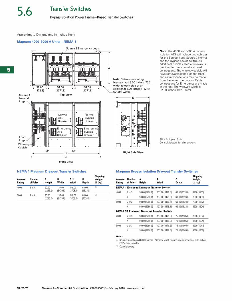
V2-T5-70 Volume 2—Commercial Distribution CA08100003E—February 2018 www.eaton.com
5
5
5
5
5
5
5
5
5
5
5
5
5
5
5
5
5
5
5
5
5
5
5
5
5
5
5
5
5
5
5.6 Transfer Switches
Bypass Isolation Power Frame–Based Transfer Switches
Approximate Dimensions in Inches (mm)
Magnum 4000–5000 A Units—NEMA 1
NEMA 1 Magnum Drawout Transfer Switches Magnum Bypass Isolation Drawout Transfer Switches
Notes1 Seismic mounting adds 3.00 inches (76.2 mm) width to each side or additional 6.00 inches
(152.4 mm) to width.2 Consult factory.
Source 2 Emergency Lugs
Load Lugs
Source 1 NormalLugs
A
54.00(1371.8)
54.00(1371.8)
32.00(872.8)
D
Normal ATS Breaker
Normal Bypass Breaker
Emergency ATS Breaker
EmergencyBypass Breaker
Wireway Cubicle
SP SP
CB
Note: Seismic mounting brackets add 3.00 inches (76.2) width to each side or an additional 6.00 inches (152.4)to total width.
Top View
Front View
Right Side View
SP = Shipping Split.Consult factory for dimensions.
Note: The 4000 and 5000 A bypass isolation ATS will include two cubicles for the Source 1 and Source 2 Normal and the Bypass power switch. An additional cubicle called a wireway is provided for the Normal and Load connections. The wireway cubicle will have removable panels on the front, and cable connections may be made from the top or the bottom. Cable connections for Emergency are madein the rear. The wireway width is 32.00 inches (812.8 mm).
AmpereRating
Numberof Poles
AHeight
BWidth
C 1Width
DDepth
ShippingWeight Lb (kg)
4000 3 or 4 90.00(2286.0)
137.00(3479.8)
146.00(3708.4)
60.00(1524.0)
2
5000 3 or 4 90.00(2286.0)
137.00(3479.8)
146.00(3708.4)
60.00(1524.0)
2
Ampere Rating
Number of Poles
A Height
B Width
C Depth
ShippingWeight Lb (kg)
NEMA 1 Enclosed Drawout Transfer Switch
4000 2 or 3 90.00 (2286.0) 137.00 (3479.8) 60.00 (1524.0) 6900 (3133)
4 90.00 (2286.0) 137.00 (3479.8) 60.00 (1524.0) 7600 (3450)
5000 2 or 3 90.00 (2286.0) 137.00 (3479.8) 60.00 (1524.0) 7900 (3587)
4 90.00 (2286.0) 137.00 (3479.8) 60.00 (1524.0) 8600 (3904)
NEMA 3R Enclosed Drawout Transfer Switch
4000 2 or 3 90.00 (2286.0) 137.00 (3479.8) 75.00 (1905.0) 7900 (3587)
4 90.00 (2286.0) 137.00 (3479.8) 75.00 (1905.0) 8600 (3904)
5000 2 or 3 90.00 (2286.0) 137.00 (3479.8) 75.00 (1905.0) 8900 (4041)
4 90.00 (2286.0) 137.00 (3479.8) 75.00 (1905.0) 9600 (4358)
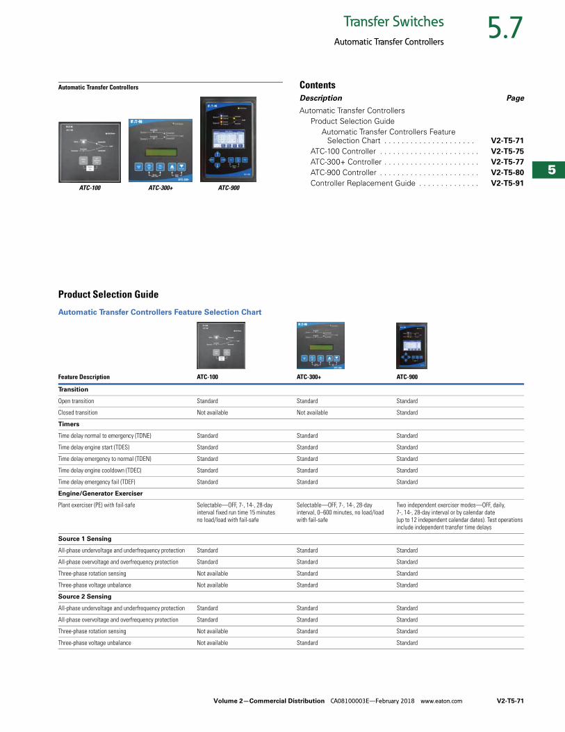
Volume 2—Commercial Distribution CA08100003E—February 2018 www.eaton.com V2-T5-71
5
5
5
5
5
5
5
5
5
5
5
5
5
5
5
5
5
5
5
5
5
5
5
5
5
5
5
5
5
5
5.7Transfer Switches
Automatic Transfer Controllers
Automatic Transfer Controllers
ATC-100 ATC-300+ ATC-900
ContentsDescription Page
Automatic Transfer ControllersProduct Selection Guide
Automatic Transfer Controllers Feature Selection Chart . . . . . . . . . . . . . . . . . . . . . V2-T5-71
ATC-100 Controller . . . . . . . . . . . . . . . . . . . . . . . V2-T5-75
ATC-300+ Controller . . . . . . . . . . . . . . . . . . . . . . V2-T5-77
ATC-900 Controller . . . . . . . . . . . . . . . . . . . . . . . V2-T5-80
Controller Replacement Guide . . . . . . . . . . . . . . V2-T5-91
Product Selection Guide
Automatic Transfer Controllers Feature Selection Chart
Feature Description ATC-100 ATC-300+ ATC-900
Transition
Open transition Standard Standard Standard
Closed transition Not available Not available Standard
Timers
Time delay normal to emergency (TDNE) Standard Standard Standard
Time delay engine start (TDES) Standard Standard Standard
Time delay emergency to normal (TDEN) Standard Standard Standard
Time delay engine cooldown (TDEC) Standard Standard Standard
Time delay emergency fail (TDEF) Standard Standard Standard
Engine/Generator Exerciser
Plant exerciser (PE) with fail-safe Selectable—OFF, 7-, 14-, 28-day interval fixed run time 15 minutes no load/load with fail-safe
Selectable—OFF, 7-, 14-, 28-day interval, 0–600 minutes, no load/load with fail-safe
Two independent exerciser modes—OFF, daily, 7-, 14-, 28-day interval or by calendar date (up to 12 independent calendar dates). Test operations include independent transfer time delays
Source 1 Sensing
All-phase undervoltage and underfrequency protection Standard Standard Standard
All-phase overvoltage and overfrequency protection Standard Standard Standard
Three-phase rotation sensing Not available Standard Standard
Three-phase voltage unbalance Not available Standard Standard
Source 2 Sensing
All-phase undervoltage and underfrequency protection Standard Standard Standard
All-phase overvoltage and overfrequency protection Standard Standard Standard
Three-phase rotation sensing Not available Standard Standard
Three-phase voltage unbalance Not available Standard Standard
V2-T5-72 Volume 2—Commercial Distribution CA08100003E—February 2018 www.eaton.com
5
5
5
5
5
5
5
5
5
5
5
5
5
5
5
5
5
5
5
5
5
5
5
5
5
5
5
5
5
5
5.7 Transfer Switches
Automatic Transfer Controllers
Automatic Transfer Controllers Feature Selection Chart, continued
Feature Description ATC-100 ATC-300+ ATC-900
Manual Controls
Test operators Standard Standard Standard
Four-position test selector switch (FPSS) Not available Not available Optional
Time delay bypass pushbutton Not available Standard Standard
Maintenance selector switch (MSS) Not available Optional Optional
Automatic/manual operation selector switch Not available Optional Optional
Automatic/manual retransfer selector switch Not available Not available Optional
Manual retransfer pushbutton Not available Optional Optional
Indications / Status Display
Source 1 connected / Source 2 connected Standard Standard Standard
Source 1 available / Source 2 available Standard Standard Standard
Source 1 tripped / Source 2 tripped Standard Standard Standard
Customer Outputs
Source 1 / Source 2 present contacts Not available Standard—2NO and 2NC Not available
Source 1 available / Source 2 available contacts Not available Not available Standard—1 Form C
Load sequence Not available Not available Configurable—1 Form C
Selective load shed Not available Not available Configurable—1 Form C
Load bank control Not available Not available Configurable—1 Form C
Pre-transfer Not available Standard—1 Form C Configurable—1 Form C
Pre-/post-transfer Not available Not available Configurable—1 Form C
Source 1 connected Not available Not available Configurable—1 Form C
Source 2 connected Not available Not available Configurable—1 Form C
ATS not in automatic Not available Not available Configurable—1 Form C
General alarm Not available Standard Configurable—1 Form C
ATS in test Not available Not available Configurable—1 Form C
Engine test aborted Not available Not available Configurable—1 Form C
Cooldown in process Not available Not available Configurable—1 Form C
Engine start contact status Not available Not available Configurable—1 Form C
Emergency inhibit on Not available Not available Configurable—1 Form C
Switch Position Indication Contact
Source 1 position indication contact Not available Standard—1 Form C Standard—1 Form C
Source 2 position indication contact Not available Standard—1 Form C Standard—1 Form C
Volume 2—Commercial Distribution CA08100003E—February 2018 www.eaton.com V2-T5-73
5
5
5
5
5
5
5
5
5
5
5
5
5
5
5
5
5
5
5
5
5
5
5
5
5
5
5
5
5
5
5.7Transfer Switches
Automatic Transfer Controllers
Automatic Transfer Controllers Feature Selection Chart, continued
Feature Description ATC-100 ATC-300+ ATC-900
Customer Inputs
Go to emergency (Source 2) Not available Standard Standard—configurable input
Load shed / emergency inhibit Not available Standard Standard—configurable input
Monitor mode Not available Optional Standard—configurable input
Bypass timers Not available Not available Standard—configurable input
Lockout Not available Optional Standard—configurable input
Manual retransfer on/off Not available Programmed Standard—configurable input
Manual retransfer Not available Standard Standard—configurable input
Slave in Not available Not available Standard—configurable input
Remote engine test Not available Not available Standard—configurable input
Preferred source selection Not available Not available Standard—configurable input
Remote load test Not available Not available Standard—configurable input
ATS on bypass Not available Not available Standard—configurable input
Integrated Metering
DCT metering—load side Not available Not available Optional
Communications
Modbus RTU Not available Optional Standard
Modbus TCP/IP Not available Optional Optional
Transfer Mode Open Transition
Delayed—time delay neutral Standard—based on construction Standard—based on construction Standard—based on construction
In-phase monitoring Standard—based on construction Standard—based on construction Standard—based on construction
Load voltage decay Not available Not available Standard—based on construction
Transfer Mode Closed Transition
Closed transition Not available Not available Standard—based on construction
Closed transition/In-phase Not available Not available Standard—based on construction
Closed transition/In-phase/Time delay neutral
Not available Not available Standard—based on construction
Closed transition/In-phase/Load voltage delay
Not available Not available Standard—based on construction
Service Entrance Rating
Source 1, Source 2 or both, and with and without ground fault protection
Not available Optional Optional
Stainless Steel Cover
SS lockable cover for controller Optional Optional

V2-T5-74 Volume 2—Commercial Distribution CA08100003E—February 2018 www.eaton.com
5
5
5
5
5
5
5
5
5
5
5
5
5
5
5
5
5
5
5
5
5
5
5
5
5
5
5
5
5
5
5.7 Transfer Switches
Automatic Transfer Controllers
Automatic Transfer Controllers Feature Selection Chart, continued
Feature Description ATC-100 ATC-300+ ATC-900
Programming Selections
Time delay normal to emergency 3 seconds (fixed) 0–1800 seconds 0–9999 seconds
Time delay emergency to normal 5 minutes (fixed) 0–1800 seconds 0–9999 seconds
Time delay engine cooldown 5 minutes (fixed) 0–1800 seconds 0–9999 seconds
Time delay engine start 3 seconds (fixed) 0–120 seconds 0–120 seconds
Time delay neutral Not available 0–120 seconds 0–120 seconds or based on load voltage decay of 2–30% of nominal
Time delay Source 2 fail Not available 0–6 seconds 0–6 seconds
Time delay voltage unbalance Not available 10–30 seconds 10–30 seconds
Voltage unbalance three-phase Not available 0 or 1 (1 = enabled) Enabled or disabled
Phase reversal three-phase Not available Dropout 5–20%Pickup (DO –2%) –3%
Dropout 5–20%Pickup (DO –2%) –3%
In-phase Not available 0 or 1 (1 = enabled)
Load sequencing Not available Not available 0–120 seconds (up to xx devices)
Pre-transfer signal Not available 1–120 seconds 0–120 seconds
Plant exerciser Selectable—OFF, 7-, 14-, 28-day interval, fixed run time 15 minutes, no load/load with fail-safe
Selectable—OFF, 7-, 14-, 28-day interval, 0–600 minutes, no load/load with fail-safe
Two independent exerciser modes—OFF, daily, 7-, 14-, 28-day interval or by calendar date (up to 12 independent calendar dates). Test operations include independent transfer time delays
Preferred source selection Not available Not available Source 1, Source 2 or None
Commitment to transfer in TDNE Not available Not available Enabled or disabled
Retransfer mode N/A automatic or manual Not available Optional Enabled or disabled
Auto daylight saving time adjustment Not available Not available Enabled or disabled
System selection Utility/generator Utility/generator or dual utility Utility/generator, dual utility, dual generator or three source
Voltage Specification
System application voltage Up to 480 Vac Up to 600 Vac Up to 600 Vac
Voltage measurements Source 1 and 2 Source 1 and 2—VAB, VBC and VCA Source 1, 2 and load—VAB, VBC and VCA
Voltage measurement range 120–480 Vac 0–790 Vac rms 0–700 Vac rms
Operating power 95–145 Vac 65–145 Vac 65–160 Vac24 Vdc (W10%)
Frequency Specifications
Frequency measurements Source 2 Source 1 and 2 Source 1 and 2
Frequency measurement range 50–60 Hz 40–70 Hz 40–70 Hz
Environmental Specifications
Operating temperature range –20 to +70 °C –20 to +70 °C –20 to +70 °C
Storage temperature range –30 to +85 °C –30 to +85 °C –30 to +85 °C
Operating humidity 0 to 95% relative humidity (noncondensing) 0 to 95% relative humidity (noncondensing) 0 to 95% relative humidity (noncondensing)
Operating environment Resistant to ammonia, methane, nitrogen, hydrogen and hydrocarbons
Resistant to ammonia, methane, nitrogen, hydrogen and hydrocarbons
Resistant to ammonia, methane, nitrogen, hydrogen and hydrocarbons
Front Panel Indication
Mimic diagram with LED indication Unit status, Source 1 and 2 available and connected (five total)
Unit status, Source 1 and 2 available and connected (five total)
Unit status, Source 1 and 2 available and connected (seven total)
Main display N/A LCD-based display, 2 lines, 16 characters LCD display, 4.3 inch color TFT (480x272)
Display language N/A English, French and Spanish English, French and Spanish
Communications capable N/A Modbus 485 Modbus 485 or Ethernet TCP/IP
Enclosure compatibility NEMA 1 and 3R NEMA 1, 12, 3R and 4X UV resistant faceplate NEMA 1, 12, 3R and 4X UV resistant faceplate
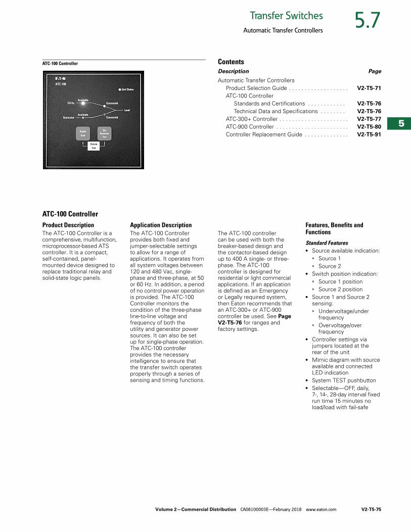
Volume 2—Commercial Distribution CA08100003E—February 2018 www.eaton.com V2-T5-75
5
5
5
5
5
5
5
5
5
5
5
5
5
5
5
5
5
5
5
5
5
5
5
5
5
5
5
5
5
5
5.7Transfer Switches
Automatic Transfer Controllers
ATC-100 Controller ContentsDescription Page
Automatic Transfer ControllersProduct Selection Guide . . . . . . . . . . . . . . . . . . . V2-T5-71
ATC-100 ControllerStandards and Certifications . . . . . . . . . . . . V2-T5-76
Technical Data and Specifications . . . . . . . . V2-T5-76
ATC-300+ Controller . . . . . . . . . . . . . . . . . . . . . . V2-T5-77
ATC-900 Controller . . . . . . . . . . . . . . . . . . . . . . . V2-T5-80
Controller Replacement Guide . . . . . . . . . . . . . . V2-T5-91
ATC-100 ControllerProduct DescriptionThe ATC-100 Controller is a comprehensive, multifunction, microprocessor-based ATS controller. It is a compact, self-contained, panel-mounted device designed to replace traditional relay and solid-state logic panels.
Application DescriptionThe ATC-100 Controller provides both fixed and jumper-selectable settings to allow for a range of applications. It operates from all system voltages between 120 and 480 Vac, single-phase and three-phase, at 50 or 60 Hz. In addition, a period of no control power operation is provided. The ATC-100 Controller monitors the condition of the three-phase line-to-line voltage and frequency of both the utility and generator power sources. It can also be set up for single-phase operation. The ATC-100 controller provides the necessary intelligence to ensure that the transfer switch operates properly through a series of sensing and timing functions.
The ATC-100 controller can be used with both the breaker-based design and the contactor-based design up to 400 A single- or three-phase. The ATC-100 controller is designed for residential or light commercial applications. If an application is defined as an Emergency or Legally required system, then Eaton recommends that an ATC-300+ or ATC-900 controller be used. See Page V2-T5-76 for ranges and factory settings.
Features, Benefits and Functions
Standard Features● Source available indication:
● Source 1● Source 2
● Switch position indication:● Source 1 position ● Source 2 position
● Source 1 and Source 2 sensing:● Undervoltage/under
frequency● Overvoltage/over
frequency● Controller settings via
jumpers located at the rear of the unit
● Mimic diagram with source available and connected LED indication
● System TEST pushbutton● Selectable—OFF, daily,
7-, 14-, 28-day interval fixed run time 15 minutes no load/load with fail-safe
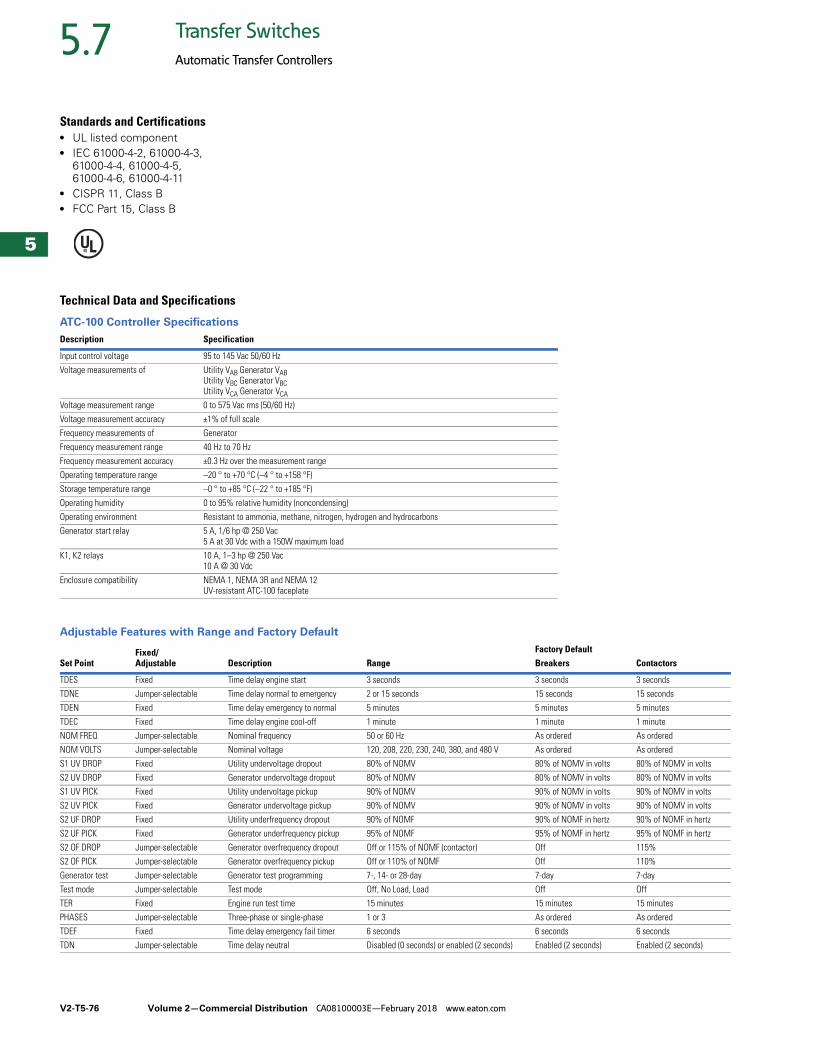
V2-T5-76 Volume 2—Commercial Distribution CA08100003E—February 2018 www.eaton.com
5
5
5
5
5
5
5
5
5
5
5
5
5
5
5
5
5
5
5
5
5
5
5
5
5
5
5
5
5
5
5.7 Transfer Switches
Automatic Transfer Controllers
Standards and Certifications● UL listed component● IEC 61000-4-2, 61000-4-3,
61000-4-4, 61000-4-5, 61000-4-6, 61000-4-11
● CISPR 11, Class B● FCC Part 15, Class B
Technical Data and Specifications
ATC-100 Controller Specifications
Adjustable Features with Range and Factory Default
Description Specification
Input control voltage 95 to 145 Vac 50/60 Hz
Voltage measurements of Utility VAB Generator VABUtility VBC Generator VBCUtility VCA Generator VCA
Voltage measurement range 0 to 575 Vac rms (50/60 Hz)
Voltage measurement accuracy ±1% of full scale
Frequency measurements of Generator
Frequency measurement range 40 Hz to 70 Hz
Frequency measurement accuracy ±0.3 Hz over the measurement range
Operating temperature range –20 ° to +70 °C (–4 ° to +158 °F)
Storage temperature range –0 ° to +85 °C (–22 ° to +185 °F)
Operating humidity 0 to 95% relative humidity (noncondensing)
Operating environment Resistant to ammonia, methane, nitrogen, hydrogen and hydrocarbons
Generator start relay 5 A, 1/6 hp @ 250 Vac5 A at 30 Vdc with a 150W maximum load
K1, K2 relays 10 A, 1–3 hp @ 250 Vac10 A @ 30 Vdc
Enclosure compatibility NEMA 1, NEMA 3R and NEMA 12UV-resistant ATC-100 faceplate
Set PointFixed/Adjustable Description Range
Factory DefaultBreakers Contactors
TDES Fixed Time delay engine start 3 seconds 3 seconds 3 seconds
TDNE Jumper-selectable Time delay normal to emergency 2 or 15 seconds 15 seconds 15 seconds
TDEN Fixed Time delay emergency to normal 5 minutes 5 minutes 5 minutes
TDEC Fixed Time delay engine cool-off 1 minute 1 minute 1 minute
NOM FREQ Jumper-selectable Nominal frequency 50 or 60 Hz As ordered As ordered
NOM VOLTS Jumper-selectable Nominal voltage 120, 208, 220, 230, 240, 380, and 480 V As ordered As ordered
S1 UV DROP Fixed Utility undervoltage dropout 80% of NOMV 80% of NOMV in volts 80% of NOMV in volts
S2 UV DROP Fixed Generator undervoltage dropout 80% of NOMV 80% of NOMV in volts 80% of NOMV in volts
S1 UV PICK Fixed Utility undervoltage pickup 90% of NOMV 90% of NOMV in volts 90% of NOMV in volts
S2 UV PICK Fixed Generator undervoltage pickup 90% of NOMV 90% of NOMV in volts 90% of NOMV in volts
S2 UF DROP Fixed Utility underfrequency dropout 90% of NOMF 90% of NOMF in hertz 90% of NOMF in hertz
S2 UF PICK Fixed Generator underfrequency pickup 95% of NOMF 95% of NOMF in hertz 95% of NOMF in hertz
S2 OF DROP Jumper-selectable Generator overfrequency dropout Off or 115% of NOMF (contactor) Off 115%
S2 OF PICK Jumper-selectable Generator overfrequency pickup Off or 110% of NOMF Off 110%
Generator test Jumper-selectable Generator test programming 7-, 14- or 28-day 7-day 7-day
Test mode Jumper-selectable Test mode Off, No Load, Load Off Off
TER Fixed Engine run test time 15 minutes 15 minutes 15 minutes
PHASES Jumper-selectable Three-phase or single-phase 1 or 3 As ordered As ordered
TDEF Fixed Time delay emergency fail timer 6 seconds 6 seconds 6 seconds
TDN Jumper-selectable Time delay neutral Disabled (0 seconds) or enabled (2 seconds) Enabled (2 seconds) Enabled (2 seconds)
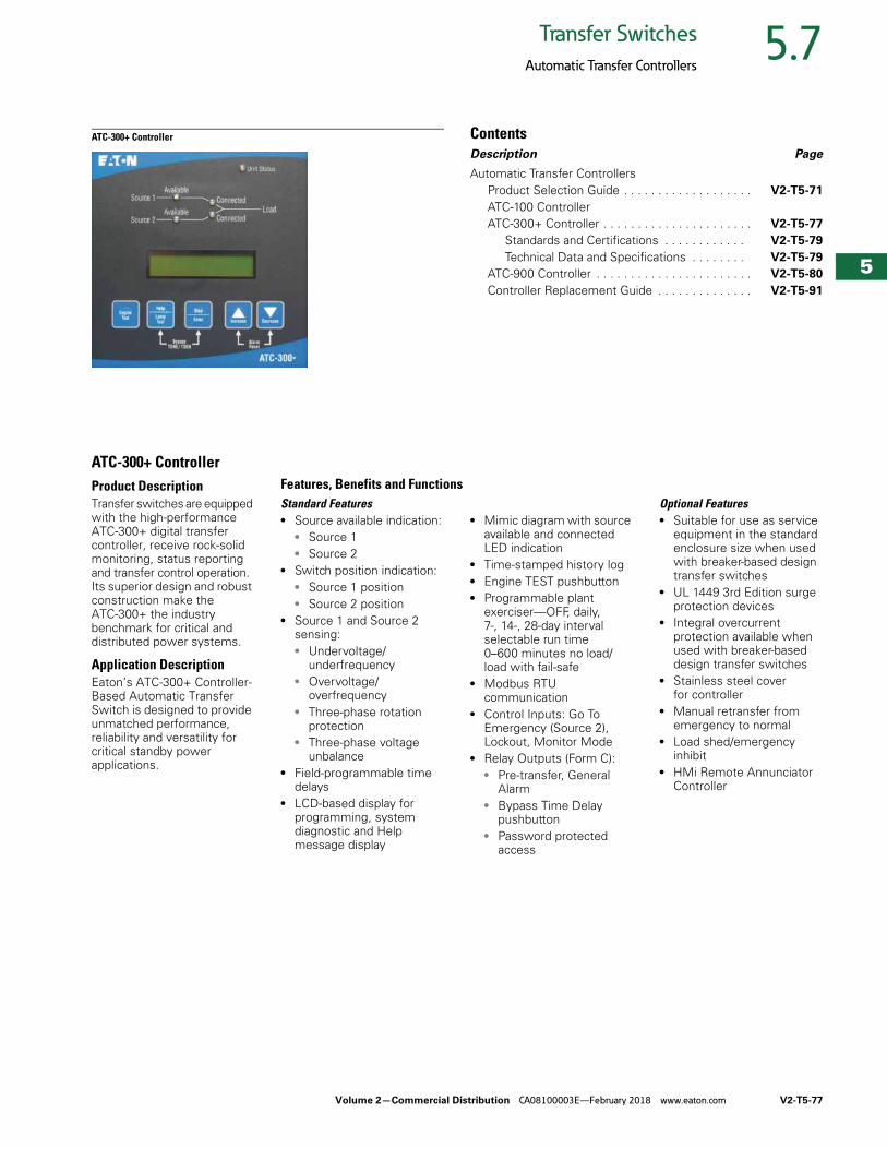
Volume 2—Commercial Distribution CA08100003E—February 2018 www.eaton.com V2-T5-77
5
5
5
5
5
5
5
5
5
5
5
5
5
5
5
5
5
5
5
5
5
5
5
5
5
5
5
5
5
5
5.7Transfer Switches
Automatic Transfer Controllers
ATC-300+ Controller ContentsDescription Page
Automatic Transfer ControllersProduct Selection Guide . . . . . . . . . . . . . . . . . . . V2-T5-71
ATC-100 ControllerATC-300+ Controller . . . . . . . . . . . . . . . . . . . . . . V2-T5-77
Standards and Certifications . . . . . . . . . . . . V2-T5-79
Technical Data and Specifications . . . . . . . . V2-T5-79
ATC-900 Controller . . . . . . . . . . . . . . . . . . . . . . . V2-T5-80
Controller Replacement Guide . . . . . . . . . . . . . . V2-T5-91
ATC-300+ ControllerProduct DescriptionTransfer switches are equipped with the high-performance ATC-300+ digital transfer controller, receive rock-solid monitoring, status reporting and transfer control operation. Its superior design and robust construction make the ATC-300+ the industry benchmark for critical and distributed power systems.
Application DescriptionEaton’s ATC-300+ Controller-Based Automatic Transfer Switch is designed to provide unmatched performance, reliability and versatility for critical standby power applications.
Standard Features● Source available indication:
● Source 1● Source 2
● Switch position indication:● Source 1 position ● Source 2 position
● Source 1 and Source 2 sensing:● Undervoltage/
underfrequency● Overvoltage/
overfrequency● Three-phase rotation
protection● Three-phase voltage
unbalance● Field-programmable time
delays● LCD-based display for
programming, system diagnostic and Help message display
● Mimic diagram with source available and connected LED indication
● Time-stamped history log● Engine TEST pushbutton● Programmable plant
exerciser—OFF, daily, 7-, 14-, 28-day interval selectable run time 0–600 minutes no load/load with fail-safe
● Modbus RTU communication
● Control Inputs: Go To Emergency (Source 2), Lockout, Monitor Mode
● Relay Outputs (Form C):● Pre-transfer, General
Alarm● Bypass Time Delay
pushbutton● Password protected
access
Optional Features● Suitable for use as service
equipment in the standard enclosure size when used with breaker-based design transfer switches
● UL 1449 3rd Edition surge protection devices
● Integral overcurrent protection available when used with breaker-based design transfer switches
● Stainless steel cover for controller
● Manual retransfer from emergency to normal
● Load shed/emergency inhibit
● HMi Remote Annunciator Controller
Features, Benefits and Functions
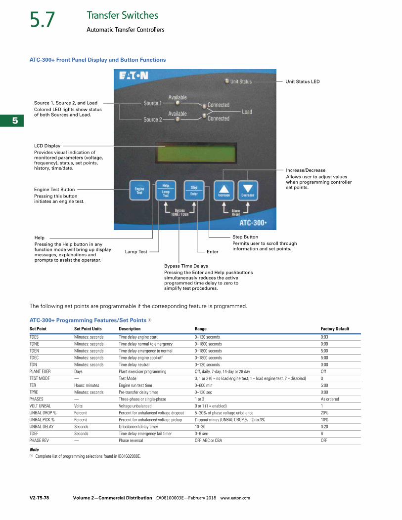
V2-T5-78 Volume 2—Commercial Distribution CA08100003E—February 2018 www.eaton.com
5
5
5
5
5
5
5
5
5
5
5
5
5
5
5
5
5
5
5
5
5
5
5
5
5
5
5
5
5
5
5.7 Transfer Switches
Automatic Transfer Controllers
ATC-300+ Front Panel Display and Button Functions
The following set points are programmable if the corresponding feature is programmed.
ATC-300+ Programming Features/Set Points 1
Note1 Complete list of programming selections found in IB01602009E.
Set Point Set Point Units Description Range Factory Default
TDES Minutes: seconds Time delay engine start 0–120 seconds 0:03
TDNE Minutes: seconds Time delay normal to emergency 0–1800 seconds 0:00
TDEN Minutes: seconds Time delay emergency to normal 0–1800 seconds 5:00
TDEC Minutes: seconds Time delay engine cool-off 0–1800 seconds 5:00
TDN Minutes: seconds Time delay neutral 0–120 seconds 0:00
PLANT EXER Days Plant exerciser programming Off, daily, 7-day, 14-day or 28 day Off
TEST MODE — Test Mode 0, 1 or 2 (0 = no load engine test, 1 = load engine test, 2 = disabled) 0
TER Hours: minutes Engine run test time 0–600 min 5:00
TPRE Minutes: seconds Pre-transfer delay timer 0–120 sec 0:00
PHASES — Three-phase or single-phase 1 or 3 As ordered
VOLT UNBAL Volts Voltage unbalanced 0 or 1 (1 = enabled) 1
UNBAL DROP % Percent Percent for unbalanced voltage dropout 5–20% of phase voltage unbalance 20%
UNBAL PICK % Percent Percent for unbalanced voltage pickup Dropout minus (UNBAL DROP % –2) to 3% 10%
UNBAL DELAY Seconds Unbalanced delay timer 10–30 0:20
TDEF Seconds Time delay emergency fail timer 0–6 sec 6
PHASE REV — Phase reversal OFF, ABC or CBA OFF
LCD Display
Provides visual indication of
monitored parameters (voltage, frequency), status, set points, history, time/date.
Source 1, Source 2, and Load
Colored LED lights show status of both Sources and Load.
Increase/Decrease
Allows user to adjust values
when programming controller set points.
Step Button
Permits user to scroll through information and set points.
Help
Pressing the Help button in any function mode will bring up display messages, explanations and
prompts to assist the operator.
Engine Test Button
Pressing this button initiates an engine test.
Lamp Test Enter
Unit Status LED
Bypass Time Delays
Pressing the Enter and Help pushbuttons
simultaneously reduces the active programmed time delay to zero to simplify test procedures.

Volume 2—Commercial Distribution CA08100003E—February 2018 www.eaton.com V2-T5-79
5
5
5
5
5
5
5
5
5
5
5
5
5
5
5
5
5
5
5
5
5
5
5
5
5
5
5
5
5
5
5.7Transfer Switches
Automatic Transfer Controllers
Standards and Certifications● UL listed component● Meets intent of
UL 991, 1008● Meets IEC 1000-4-2, 1000-
4-3, 1000-4-4, 1000-4-5, 1000-4-6, 1000-4-11
● Meets CISPR 11, Class A● Complies with FCC Part 15,
Class A
Technical Data and Specifications
ATC-300+ Controller Specifications
Description Specification
Input control voltage 65 to 145 Vac 50/60 Hz
Voltage measurements of Source 1 VAB Source 2 VABSource 1 VBC Source 2 VBCSource 1 VCA Source 2 VCA
Voltage measurement range 0 to 790 Vac RMS (50/60 Hz)
Voltage measurement accuracy ±1% of full scale
Frequency measurements of Source 1 and Source 2
Frequency measurement range 40 Hz to 70 Hz
Frequency measurement accuracy ±0.3 Hz over the measurement range
Undervoltage dropout range: Breaker/switch style ATS 50 to 97% of the nominal system voltage
Contactor style ATS 78 to 97% of the nominal system voltage
Undervoltage pickup range: Breaker/switch style ATS (Dropout +2%) to 99% of the nominal system voltage
Contactor style ATS (Dropout +2%) to 99% of the nominal system voltage
Overvoltage dropout range: Breaker/switch style ATS 105 to 120% of the nominal system voltage
Contactor style ATS 105 to 110% of the nominal system voltage
Overvoltage pickup range: Breaker/switch style ATS 103% to (dropout –2%) of the nominal system voltage
Contactor style ATS 103% to (dropout –2%) of the nominal system voltage
Underfrequency dropout range: Breaker/switch style ATS 90 to 97% of the nominal system frequency
Contactor style ATS 90 to 97% of the nominal system frequency
Underfrequency pickup range: Breaker/switch style ATS (Dropout +1Hz) to 99% of the nominal system frequency
Contactor style ATS (Dropout +1Hz) to 99% of the nominal system frequency
Overfrequency dropout range: Breaker/switch style ATS 103 to 110% of the nominal system frequency
Contactor style ATS 103 to 105% of the nominal system frequency
Overfrequency pickup range: Breaker/switch style ATS 101% to (dropout –1 Hz) of the nominal system frequency
Contactor style ATS 101% to (dropout –1 Hz) of the nominal system frequency
Operating temperature range –20 °C to +70 °C (–4 °F to +158 °F)
Storage temperature range –30 °C to +85 °C (–22 °F to +185 °F)
Operating humidity 0 to 95% relative humidity (noncondensing)
Operating environment Resistant to ammonia, methane, nitrogen, hydrogen and hydrocarbons
Generator start relay 5 A, 1/6 Hp at 250 Vac
5 A at 30 Vdc with a 150W maximum Load
K1, K2, pretransfer, alarm relays 10 A, 1–3 hp at 250 Vac
K3, K4 10 A at 30 Vdc
Applicable testing UL recognized component
Meets UL 1008
Meets Intent of UL 991
Meets IEC 1000-4-2, 1000-4-3, 1000-4-4, 1000-4-5, 1000-4-6, 1000-4-11
Meets CISPR 11, Class A
Complies with FCC Part 15, Class A
Enclosure compatibility NEMA 1, NEMA 3R and NEMA 12
UV resistant ATC-300+ faceplate
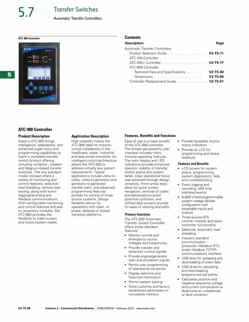
V2-T5-80 Volume 2—Commercial Distribution CA08100003E—February 2018 www.eaton.com
5
5
5
5
5
5
5
5
5
5
5
5
5
5
5
5
5
5
5
5
5
5
5
5
5
5
5
5
5
5
5.7 Transfer Switches
Automatic Transfer Controllers
ATC-900 Controller ContentsDescription Page
Automatic Transfer ControllersProduct Selection Guide . . . . . . . . . . . . . . . . . . . . V2-T5-71
ATC-100 ControllerATC-300+ Controller . . . . . . . . . . . . . . . . . . . . . . . V2-T5-77
ATC-900 ControllerTechnical Data and Specifications . . . . . . . . V2-T5-90
Dimensions . . . . . . . . . . . . . . . . . . . . . . . . . V2-T5-90
Controller Replacement Guide . . . . . . . . . . . . . . . V2-T5-91
ATC-900 ControllerProduct DescriptionEaton’s ATC-900 brings intelligence, adaptability, and enhanced supervisory and programming capabilities to Eaton’s complete transfer switch product offering including contactor-, breaker- and Magnum-based transfer switches. The one standard model concept offers a variety of monitoring and control features, selective load shedding, remote load testing, along with event logging/recording and Modbus communications. With configurable monitoring and control features and add-on accessory modules, the ATC-900 provides the flexibility to meet current and future system needs.
Application DescriptionHigh reliability makes the ATC-900 ideal for mission-critical installations in the healthcare, water, industrial and data center industries. An intelligent control architecture allows the ATC-900 to address virtually any system requirements. Typical applications include utility-to-utility, utility-to-generator and generator-to-generator transfer pairs, and advanced programming features provide for control of three-source systems. Design flexibility allows for operations with open, in-phase, delayed or closed transition platforms.
Ease of use is a major benefit of the ATC-900 controller. The simple yet powerful user interface includes many intuitive operating features. The color display and LED indications provide enhanced operator visibility of transfer switch status and system detail. Clear operational focus was achieved through design simplicity. Front arrow keys allow for quick screen navigation, removal of codes and abbreviations avoid potential confusion, and refined data screens provide for ease of viewing and edits.
Primary FunctionsThe ATC-900 Automatic Transfer Switch Controller offers these standard features:● Monitor normal and
emergency source voltages and frequencies
● Provide transfer and retransfer control signals
● Provide engine/generator start and shutdown signals
● Permit user programming of operational set points
● Display real-time and historical information
● Permit system testing● Store customer and factory
established parameters in nonvolatile memory
● Provide faceplate source status indication
● Provide an LCD for programming and status readouts
Features and Benefits● LCD screen for system
status, programming, system diagnostics, help, and troubleshooting
● Event logging and recording, 450 time stamped events
● 0–600 V field programmable system voltage flexible configuration with assignable inputs and outputs
● Three-source ATS control—master and slave controller functionality
● Selective, automatic load shedding
● Industry standard communication protocols—Modbus RTU and/or Modbus TCP/IP communications interface
● USB drive for uploading and downloading of event data
● USB drive for uploading and downloading programmed set points
● Calculates positive and negative sequence voltage and current components to determine an unbalanced or fault condition
Features, Benefits and Functions
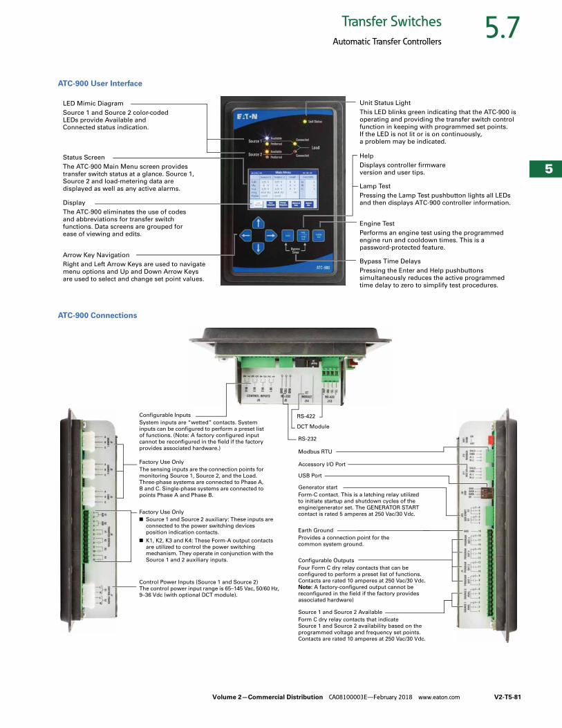
Volume 2—Commercial Distribution CA08100003E—February 2018 www.eaton.com V2-T5-81
5
5
5
5
5
5
5
5
5
5
5
5
5
5
5
5
5
5
5
5
5
5
5
5
5
5
5
5
5
5
5.7Transfer Switches
Automatic Transfer Controllers
ATC-900 User Interface
ATC-900 Connections
Status Screen
The ATC-900 Main Menu screen provides transfer switch status at a glance. Source 1, Source 2 and load-metering data are
displayed as well as any active alarms.
LED Mimic Diagram
Source 1 and Source 2 color-coded LEDs provide Available and Connected status indication.
Unit Status Light
This LED blinks green indicating that the ATC-900 is operating and providing the transfer switch control function in keeping with programmed set points.
If the LED is not lit or is on continuously, a problem may be indicated.
Help
Displays controller firmware version and user tips.
Arrow Key Navigation
Right and Left Arrow Keys are used to navigate
menu options and Up and Down Arrow Keys are used to select and change set point values.
Display
The ATC-900 eliminates the use of codes
and abbreviations for transfer switch functions. Data screens are grouped for ease of viewing and edits.
Lamp Test
Pressing the Lamp Test pushbutton lights all LEDs and then displays ATC-900 controller information.
Engine Test
Performs an engine test using the programmed engine run and cooldown times. This is a password-protected feature.
Bypass Time Delays
Pressing the Enter and Help pushbuttons simultaneously reduces the active programmed
time delay to zero to simplify test procedures.
Configurable Inputs
System inputs are “wetted” contacts. System
inputs can be configured to perform a preset list
of functions. (Note: A factory configured input
cannot be reconfigured in the field if the factory
provides associated hardware.)
Factory Use Only
The sensing inputs are the connection points for
monitoring Source 1, Source 2, and the Load.
Three-phase systems are connected to Phase A,
B and C. Single-phase systems are connected to
points Phase A and Phase B.
Factory Use Only
■ Source 1 and Source 2 auxiliary: These inputs are
connected to the power switching devices
position indication contacts.
■ K1, K2, K3 and K4: These Form-A output contacts
are utilized to control the power switching
mechanism. They operate in conjunction with the
Source 1 and 2 auxiliary inputs.
Control Power Inputs (Source 1 and Source 2)
The control power input range is 65–145 Vac, 50/60 Hz,
9–36 Vdc (with optional DCT module).
RS-422
DCT Module
RS-232
Modbus RTU
Accessory I/O Port
USB Port
Generator start
Form-C contact. This is a latching relay utilized
to initiate startup and shutdown cycles of the
engine/generator set. The GENERATOR START
contact is rated 5 amperes at 250 Vac/30 Vdc.
Earth Ground
Provides a connection point for the
common system ground.
Source 1 and Source 2 Available
Form C dry relay contacts that indicate
Source 1 and Source 2 availability based on the
programmed voltage and frequency set points.
Contacts are rated 10 amperes at 250 Vac/30 Vdc.
Configurable Outputs
Four Form C dry relay contacts that can be
configured to perform a preset list of functions.
Contacts are rated 10 amperes at 250 Vac/30 Vdc.
Note: A factory-configured output cannot be
reconfigured in the field if the factory provides
associated hardware)
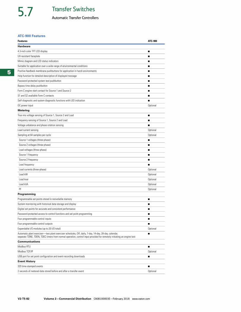
V2-T5-82 Volume 2—Commercial Distribution CA08100003E—February 2018 www.eaton.com
5
5
5
5
5
5
5
5
5
5
5
5
5
5
5
5
5
5
5
5
5
5
5
5
5
5
5
5
5
5
5.7 Transfer Switches
Automatic Transfer Controllers
ATC-900 Features
Features ATC-900
Hardware
4.3-inch color TFT LCD display ■
UV-resistant faceplate ■
Mimic diagram and LED status indicators ■
Suitable for application over a wide range of environmental conditions ■
Positive feedback membrane pushbuttons for application in harsh environments ■
Help function for detailed description of displayed message ■
Password protected system test pushbutton ■
Bypass time delay pushbutton ■
Form C engine start contact for Source 1 and Source 2 ■
S1 and S2 available Form C contacts ■
Self-diagnostic and system diagnostic functions with LED indication ■
DC power input Optional
Metering
True rms voltage sensing of Source 1, Source 2 and Load ■
Frequency sensing of Source 1, Source 2 and Load ■
Voltage unbalance and phase rotation sensing ■
Load current sensing Optional
Sampling at 64 samples per cycle Optional
Source 1 voltages (three-phase) ■
Source 2 voltages (three-phase) ■
Load voltages (three-phase) ■
Source 1 frequency ■
Source 2 frequency ■
Load frequency ■
Load currents (three-phase) Optional
Load kW Optional
Load kvar Optional
Load kVA Optional
PF Optional
Programming
Programmable set points stored in nonvolatile memory ■
System monitoring with historical data storage and display ■
Digital set points for accurate and consistent performance ■
Password-protected access to control functions and set point programming ■
Four programmable control inputs ■
Four programmable control outputs ■
Expandable I/O modules (up to 20 I/O total) Optional
Automatic plant exerciser—two plant exerciser schedules, Off, daily, 7-day, 14-day, 28-day, calendar, separate TDNE, TDEN, TDEC timers from normal operation, control input provided for remotely initiating an engine test
■
Communications
Modbus RTU ■
Modbus TCP/IP Optional
USB port for set point configuration and event-recording downloads ■
Event History
320 time-stamped events ■
2 seconds of metered data stored before and after a transfer event Optional
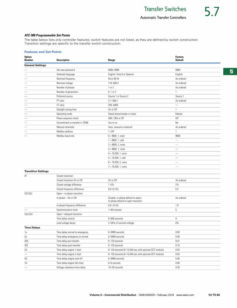
Volume 2—Commercial Distribution CA08100003E—February 2018 www.eaton.com V2-T5-83
5
5
5
5
5
5
5
5
5
5
5
5
5
5
5
5
5
5
5
5
5
5
5
5
5
5
5
5
5
5
5.7Transfer Switches
Automatic Transfer Controllers
ATC-900 Programmable Set PointsThe table below lists only controller features; switch features are not listed, as they are defined by switch construction. Transition settings are specific to the transfer switch construction.
Features and Set Points
Option Number Description Range
Factory Default
General Settings
— Set new password 0000–9999 0900
— Selected language English, French or Spanish English
— Nominal frequency 50 or 60 Hz As ordered
— Nominal voltage 110–600 V As ordered
— Number of phases 1 or 3 As ordered
— Number of generators 0, 1 or 2 1
— Preferred source Source 1 or Source 2 Source 1
— PT ratio 2:1–500:1 As ordered
— CT ratio 200–5000 —
— Daylight saving time On or Off 1
— Operating mode Stand-alone/master or slave Master
— Phase sequence check ABC, CBA or Off Off
— Commitment to transfer in TDNE Yes or no No
— Manual retransfer Auto, manual or external As ordered
— Modbus address 1–247 1
— Modbus baud rate 0 = 9600, 1, even 9600
1 = 9600, 1, odd —
2 = 9600, 2, none —
3 = 9600, 1, none —
4 = 19,200, 1, even —
5 = 19,200, 1, odd —
6 = 19,200, 2, none —
7 = 19,200, 1, none —
Transition Settings
47 Closed transition
Closed transition On or Off On or Off As ordered
Closed voltage difference 1–5% 2%
Closed frequency difference 0.0–0.3 Hz 0.3
32f/32d Open—in-phase transition
In-phase—On or Off Disable, in-phase default to alarm, in-phase default to open transition
As ordered
In-phase frequency difference 0.0–3.0 Hz 1.0
— Synchronization timer 1–60 minutes 5
32a/32d Open—delayed transition
Time delay neutral 0–600 seconds 0
Load voltage decay 2–30% of nominal voltage 6%
Time Delays
1a Time delay normal to emergency 0–9999 seconds 0:00
3a Time delay emergency to normal 0–9999 seconds 5:00
35A Time delay pre-transfer 0–120 seconds 0:01
35C Time delay post-transfer 0–120 seconds 0:10
2A Time delay engine 1 start 0–120 seconds (0–15,540 sec with optional DCT module) 0:03
— Time delay engine 2 start 0–120 seconds (0–15,540 sec with optional DCT module) 0:03
4A Time delay engine cool-off 0–9999 seconds 5:00
7A Time delay engine fail timer 0–6 seconds 0:06
— Voltage unbalance time delay 10–30 seconds 0:30
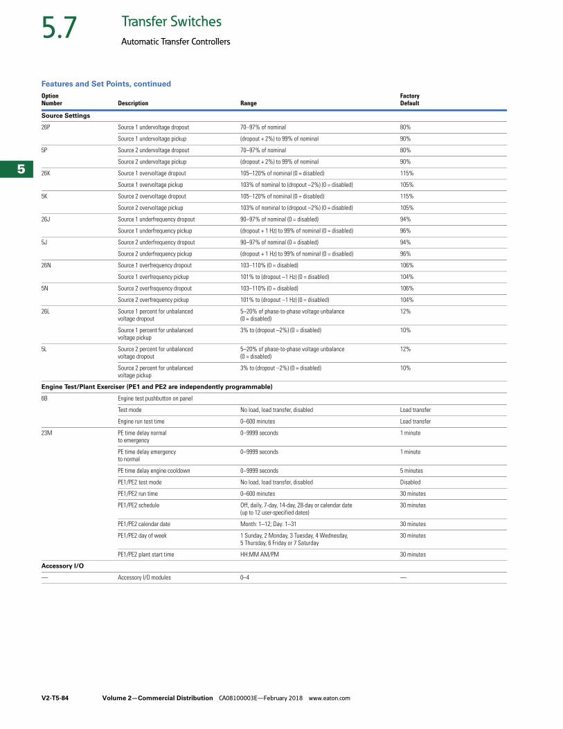
V2-T5-84 Volume 2—Commercial Distribution CA08100003E—February 2018 www.eaton.com
5
5
5
5
5
5
5
5
5
5
5
5
5
5
5
5
5
5
5
5
5
5
5
5
5
5
5
5
5
5
5.7 Transfer Switches
Automatic Transfer Controllers
Features and Set Points, continued
Option Number Description Range
Factory Default
Source Settings
26P Source 1 undervoltage dropout 70–97% of nominal 80%
Source 1 undervoltage pickup (dropout + 2%) to 99% of nominal 90%
5P Source 2 undervoltage dropout 70–97% of nominal 80%
Source 2 undervoltage pickup (dropout + 2%) to 99% of nominal 90%
26K Source 1 overvoltage dropout 105–120% of nominal (0 = disabled) 115%
Source 1 overvoltage pickup 103% of nominal to (dropout –2%) (0 = disabled) 105%
5K Source 2 overvoltage dropout 105–120% of nominal (0 = disabled) 115%
Source 2 overvoltage pickup 103% of nominal to (dropout –2%) (0 = disabled) 105%
26J Source 1 underfrequency dropout 90–97% of nominal (0 = disabled) 94%
Source 1 underfrequency pickup (dropout + 1 Hz) to 99% of nominal (0 = disabled) 96%
5J Source 2 underfrequency dropout 90–97% of nominal (0 = disabled) 94%
Source 2 underfrequency pickup (dropout + 1 Hz) to 99% of nominal (0 = disabled) 96%
26N Source 1 overfrequency dropout 103–110% (0 = disabled) 106%
Source 1 overfrequency pickup 101% to (dropout –1 Hz) (0 = disabled) 104%
5N Source 2 overfrequency dropout 103–110% (0 = disabled) 106%
Source 2 overfrequency pickup 101% to (dropout –1 Hz) (0 = disabled) 104%
26L Source 1 percent for unbalanced voltage dropout
5–20% of phase-to-phase voltage unbalance (0 = disabled)
12%
Source 1 percent for unbalanced voltage pickup
3% to (dropout –2%) (0 = disabled) 10%
5L Source 2 percent for unbalanced voltage dropout
5–20% of phase-to-phase voltage unbalance (0 = disabled)
12%
Source 2 percent for unbalanced voltage pickup
3% to (dropout –2%) (0 = disabled) 10%
Engine Test/Plant Exerciser (PE1 and PE2 are independently programmable)
6B Engine test pushbutton on panel
Test mode No load, load transfer, disabled Load transfer
Engine run test time 0–600 minutes Load transfer
23M PE time delay normal to emergency
0–9999 seconds 1 minute
PE time delay emergency to normal
0–9999 seconds 1 minute
PE time delay engine cooldown 0–9999 seconds 5 minutes
PE1/PE2 test mode No load, load transfer, disabled Disabled
PE1/PE2 run time 0–600 minutes 30 minutes
PE1/PE2 schedule Off, daily, 7-day, 14-day, 28-day or calendar date (up to 12 user-specified dates)
30 minutes
PE1/PE2 calendar date Month: 1–12; Day: 1–31 30 minutes
PE1/PE2 day of week 1 Sunday, 2 Monday, 3 Tuesday, 4 Wednesday, 5 Thursday, 6 Friday or 7 Saturday
30 minutes
PE1/PE2 plant start time HH:MM AM/PM 30 minutes
Accessory I/O
— Accessory I/O modules 0–4 —
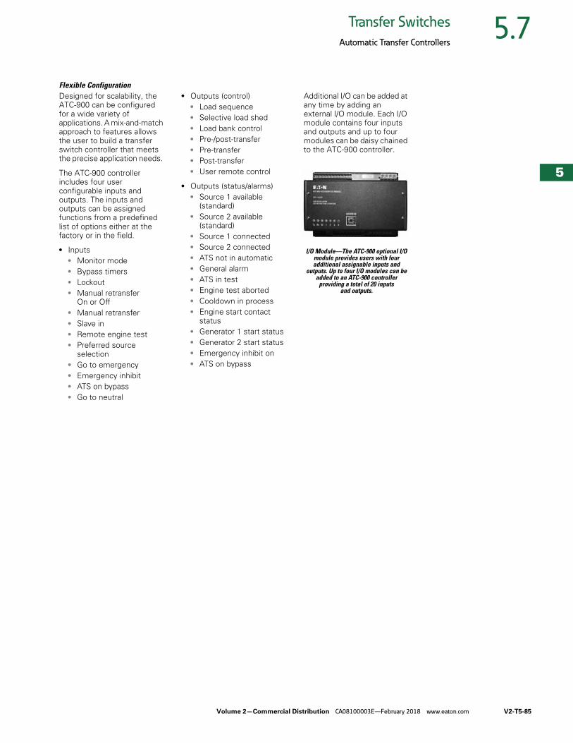
Volume 2—Commercial Distribution CA08100003E—February 2018 www.eaton.com V2-T5-85
5
5
5
5
5
5
5
5
5
5
5
5
5
5
5
5
5
5
5
5
5
5
5
5
5
5
5
5
5
5
5.7Transfer Switches
Automatic Transfer Controllers
Flexible Configuration Designed for scalability, the ATC-900 can be configured for a wide variety of applications. A mix-and-match approach to features allows the user to build a transfer switch controller that meets the precise application needs.
The ATC-900 controller includes four user configurable inputs and outputs. The inputs and outputs can be assigned functions from a predefined list of options either at the factory or in the field.
● Inputs● Monitor mode● Bypass timers● Lockout● Manual retransfer
On or Off● Manual retransfer● Slave in● Remote engine test● Preferred source
selection● Go to emergency● Emergency inhibit● ATS on bypass● Go to neutral
● Outputs (control)● Load sequence● Selective load shed● Load bank control● Pre-/post-transfer● Pre-transfer● Post-transfer● User remote control
● Outputs (status/alarms)● Source 1 available
(standard)● Source 2 available
(standard)● Source 1 connected● Source 2 connected● ATS not in automatic● General alarm● ATS in test● Engine test aborted● Cooldown in process● Engine start contact
status● Generator 1 start status● Generator 2 start status● Emergency inhibit on● ATS on bypass
Additional I/O can be added at any time by adding an external I/O module. Each I/O module contains four inputs and outputs and up to four modules can be daisy chained to the ATC-900 controller.
I/O Module—The ATC-900 optional I/O module provides users with four additional assignable inputs and
outputs. Up to four I/O modules can be added to an ATC-900 controller
providing a total of 20 inputs and outputs.
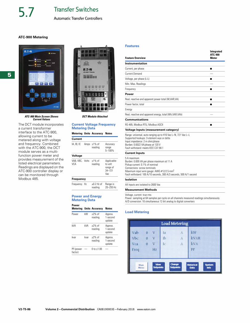
V2-T5-86 Volume 2—Commercial Distribution CA08100003E—February 2018 www.eaton.com
5
5
5
5
5
5
5
5
5
5
5
5
5
5
5
5
5
5
5
5
5
5
5
5
5
5
5
5
5
5
5.7 Transfer Switches
Automatic Transfer Controllers
ATC-900 Metering
ATC-900 Main Screen Shows Current Values
The DCT module incorporates a current transformer interface to the ATC-900, allowing current to be metered along with voltage and frequency. Combined with the ATC-900, the DCT module serves as a multi-function power meter and provides measurement of the listed electrical parameters. Readings are displayed on the ATC-900 controller display or can be monitored through Modbus 485.
DCT Module Attached
Current Voltage Frequency Metering Data
Power and Energy Metering Data
Metering Units Accuracy Notes
Current
IA, IB, IC Amps ±1% ofreading
Accuracy range 5–100%
Voltage
VAB, VBC,VCA
Volts ±1% ofreading
Applicable to volt range of 34–721 Vac
Frequency
Frequency Hz ±0.2 Hz ofreading
Range is20–255 Hz
Power Metering Units Accuracy Notes
Power kW ±2% ofreading
Approx.1-secondupdate
kVA kVA ±2% ofreading
Approx.1-secondupdate
kvar kvar ±2% ofreading
Approx.1-secondupdate
PF (powerfactor)
— 0 to ±1.00 —
Features
Load Metering
Feature Overview
Integrated ATC-900 Meter
Instrumentation
Current, per phase ■
Current Demand —
Voltage, per phase (L-L) ■
Min. Max. Readings —
Frequency ■
Power
Real, reactive and apparent power total (W,VAR,VA) ■
Power factor, total ■
Energy
Real, reactive and apparent energy, total (Wh,VAR,VAh) —
Communications
RS-485, Modbus RTU, Modbus ASCII ■
Voltage Inputs (measurement category)
Range: universal, auto-ranging up to 416 Vac L–N, 721 Vac L–LSupported hookups: 3-element wye or deltaInput impedance: 2 m ohm/phaseBurden: 0.0022 VA/phase at 120 VFault withstand: meets IEEE C37.90.1
Current Inputs
5 A maximumBurden: 0.005 VA per phase maximum at 11 APickup current: 0.1% of nominalConnections: screw terminalsMaximum input wire gauge: AWG #12/2.5 mm2
Fault withstand: 100 A/10 seconds, 300 A/3 seconds, 500 A/1 second
Isolation
All inputs are isolated to 2600 Vac
Measurement Methods
Voltage, current: true rmsPower: sampling at 64 samples per cycle on all channels measured readings simultaneouslyA/D conversion: 16 simultaneous 12-bit analog to digital converters
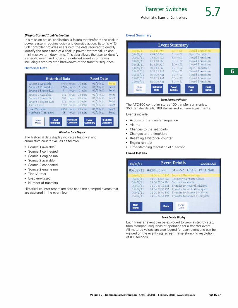
Volume 2—Commercial Distribution CA08100003E—February 2018 www.eaton.com V2-T5-87
5
5
5
5
5
5
5
5
5
5
5
5
5
5
5
5
5
5
5
5
5
5
5
5
5
5
5
5
5
5
5.7Transfer Switches
Automatic Transfer Controllers
Diagnostics and TroubleshootingIn a mission-critical application, a failure to transfer to the backup power system requires quick and decisive action. Eaton’s ATC-900 controller provides users with the data required to quickly identify the root cause of a backup power system failure and minimize system downtime. This data allows the user to identify a specific event and obtain the detailed event information including a step by step breakdown of the transfer sequence.
Historical Data
Historical Data Display
The historical data display indicates historical and cumulative counter values as follows:
● Source 1 available● Source 1 connected● Source 1 engine run● Source 2 available● Source 2 connected● Source 2 engine run● Tier IV timer● Load energized● Number of transfers
Historical counter resets are date and time-stamped events that are captured in the event log.
Event Summary
Event Summary Display
The ATC-900 controller stores 100 transfer summaries, 350 transfer details, 100 alarms and 20 time adjustments.
Events include:
● Actions of the transfer sequence● Alarms● Changes to the set points● Changes to the time/date● Resetting a historical counter● Engine run test● Time-stamping resolution of 1 second.
Event Details
Event Details Display
Each transfer event can be exploded to view a step by step, time stamped, sequence of operation for a transfer event. All metered values are also logged for each event and can be viewed on the event data screen. Time stamping resolution of 0.1 seconds.

V2-T5-88 Volume 2—Commercial Distribution CA08100003E—February 2018 www.eaton.com
5
5
5
5
5
5
5
5
5
5
5
5
5
5
5
5
5
5
5
5
5
5
5
5
5
5
5
5
5
5
5.7 Transfer Switches
Automatic Transfer Controllers
Hi-Speed Capture
High Speed Capture Display, Pre and Post Event
The ATC-900 stores metered data updated on a continuous 20 millisecond basis for specific events. The data is captured 2 seconds before and 2 seconds after the event (except for a power failure, which is 4 seconds before). Oscillographic data for 10 events is stored in the controller and may be downloaded over USB or displayed graphically.
● Events include:● Source unavailability actions that initiate a transfer sequence
(undervoltage, overvoltage, etc.)● Successful transfers (at the point of breaker/
contactor closure)● Unsuccessful transfers (at the point of breaker/contactor
failure to close or open)
Industry Standard Communication Protocol
Every ATC-900 controller includes a standard Modbus RTU communications interface with an option to upgrade to Modbus TCP/IP.
The ATC-900 is also compatible with Eaton’s Power Xpert Gateway for web-based monitoring, Modbus TCP/IP, SNMP, or BACnet/IP. The Power Xpert Gateway can be used to consolidate data from up to 64 devices, including communications ready transfer switch controllers, trip units and meters, as well as other Eaton devices. Versions of the Power Xpert Gateway include email event notification sand data-logging functionality.
Eaton ATC-900 Setpoint Editor (EASE)
The Setpoint Editor Software program allows the user to create, edit and save set point configuration files for the ATC-900 controller using a laptop. Software can be downloaded from the Eaton website (www.eaton.com/ATS).
HMi Remote Annunciator and ControllerThe HMi Remote Annunciator and Controller monitors and controls up to eight transfer switches on a 7-inch LCD touch screen. It is compatible with either Modbus RTU or Modbus TCP/IP protocols. A basic mimic bus for each transfer switch displays source availability, source connected and preferred source. Users can drill down to metered source values and event history for each transfer switch. All control features are password-protected and include engine test, transfer to emergency (peak shaving), manual retransfer and bypass time delays.
HMi Remote Annunciator and Controller
USB Programming PortEvery ATC-900 transfer switch includes a front panel, NEMA 4X rated USB port for use in configuring set points or downloading event data to a USB flash drive. To reduce the time spent on site for commissioning, set points can be configured at a PC using the ATC-900 configuration software and saved to a USB flash drive to be uploaded to one or multiple controllers. Set points are also easily copied from one controller to another.
Downloading event capture data provides the user the ability to more thoroughly analyze high-speed capture data using a PC, or data can be emailed to Eaton’s Technical Support Team when off site troubleshooting support is required.
USB Programming Port
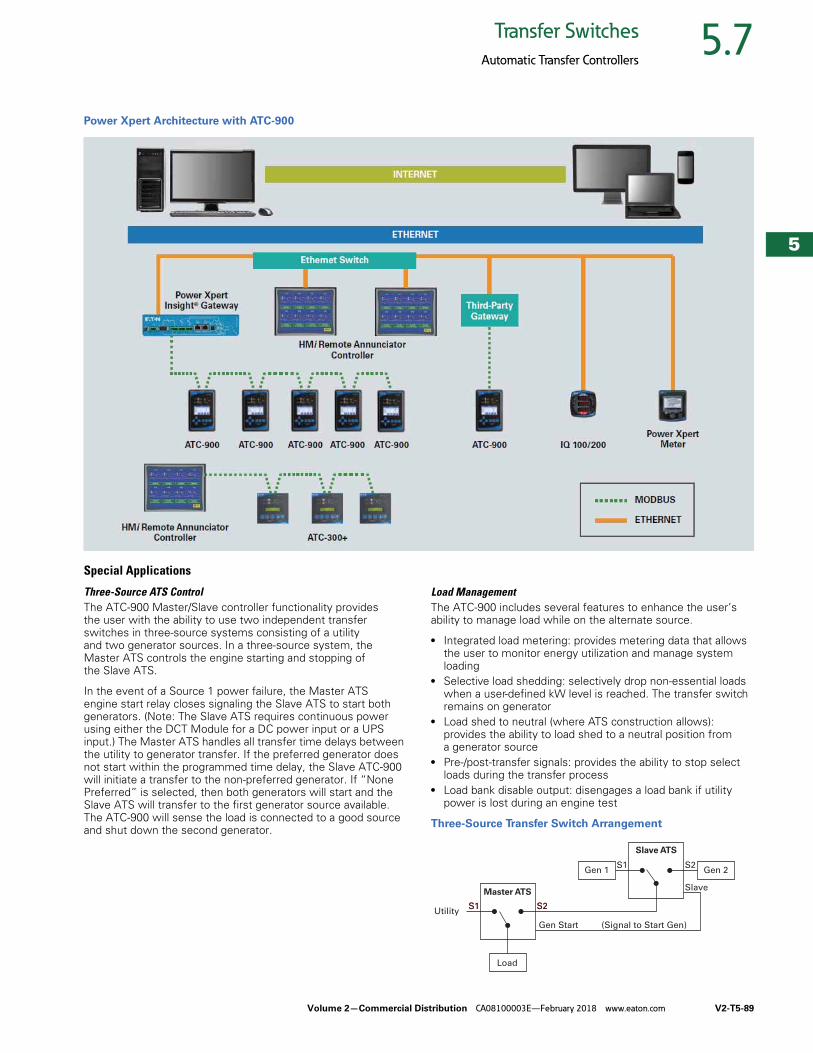
Volume 2—Commercial Distribution CA08100003E—February 2018 www.eaton.com V2-T5-89
5
5
5
5
5
5
5
5
5
5
5
5
5
5
5
5
5
5
5
5
5
5
5
5
5
5
5
5
5
5
5.7Transfer Switches
Automatic Transfer Controllers
Power Xpert Architecture with ATC-900
Special Applications
Three-Source ATS Control The ATC-900 Master/Slave controller functionality provides the user with the ability to use two independent transfer switches in three-source systems consisting of a utility and two generator sources. In a three-source system, the Master ATS controls the engine starting and stopping of the Slave ATS.
In the event of a Source 1 power failure, the Master ATS engine start relay closes signaling the Slave ATS to start both generators. (Note: The Slave ATS requires continuous power using either the DCT Module for a DC power input or a UPS input.) The Master ATS handles all transfer time delays between the utility to generator transfer. If the preferred generator does not start within the programmed time delay, the Slave ATC-900 will initiate a transfer to the non-preferred generator. If “None Preferred” is selected, then both generators will start and the Slave ATS will transfer to the first generator source available. The ATC-900 will sense the load is connected to a good source and shut down the second generator.
Load ManagementThe ATC-900 includes several features to enhance the user’s ability to manage load while on the alternate source.
● Integrated load metering: provides metering data that allows the user to monitor energy utilization and manage system loading
● Selective load shedding: selectively drop non-essential loads when a user-defined kW level is reached. The transfer switch remains on generator
● Load shed to neutral (where ATS construction allows): provides the ability to load shed to a neutral position from a generator source
● Pre-/post-transfer signals: provides the ability to stop select loads during the transfer process
● Load bank disable output: disengages a load bank if utility power is lost during an engine test
Three-Source Transfer Switch Arrangement
Utility
Load
Gen 1 Gen 2
Master ATS
Slave ATS
S1 S2
Gen Start (Signal to Start Gen)
S1 S2
S1 S2
Slave
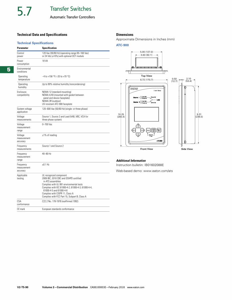
V2-T5-90 Volume 2—Commercial Distribution CA08100003E—February 2018 www.eaton.com
5
5
5
5
5
5
5
5
5
5
5
5
5
5
5
5
5
5
5
5
5
5
5
5
5
5
5
5
5
5
5.7 Transfer Switches
Automatic Transfer Controllers
Technical Data and Specifications
Technical Specifications
DimensionsApproximate Dimensions in Inches (mm)
ATC-900
Additional InformationInstruction bulletin: IB01602088E
Web-based demo: www.eaton.com/ats
Parameter Specification
Control power
120 Vac (50/60 Hz) (operating range 65–160 Vac) or 24 Vdc (±10%) with optional DCT module
Power consumption
18 VA
Environmental conditions
Operating temperature
–4 to +158 °F (–20 to +70 °C)
Operating humidity
Up to 90% relative humidity (noncondensing)
Enclosure compatibility
NEMA 12 (standard mounting)NEMA 4/4X (mounted with gasket between
panel and device faceplate)NEMA 3R (outdoor)UV resistant ATC-900 faceplate
System voltage application
120–600 Vac (50/60 Hz) (single- or three-phase)
Voltage measurements
Source 1, Source 2 and Load (VAB, VBC, VCA forthree-phase system)
Voltage measurement range
0–700 Vac
Voltage measurement accuracy
±1% of reading
Frequency measurements
Source 1 and Source 2
Frequency measurement range
40–80 Hz
Frequency measurement accuracy
±0.1 Hz
Applicable testing
UL recognized component2009 IBC, 2010 CBC and OSHPD certified
in ATS assembliesComplies with UL 991 environmental testsComplies with IEC 61000-4-2, 61000-4-3, 61000-4-4,
61000-4-5 and 61000-4-6Complies with CISPR 11, Class AComplies with FCC Part 15, Subpart B, Class A
CSA conformance
C22.2 No. 178-1978 (reaffirmed 1992)
CE mark European standards conformance
Front View Side View
Top View
5.00 (127.0)
3.63 (92.1)
6.72 (170.7)
10.25(260.4)
0.50 (12.7)
2.10 (53.4)
9.31(236.5)
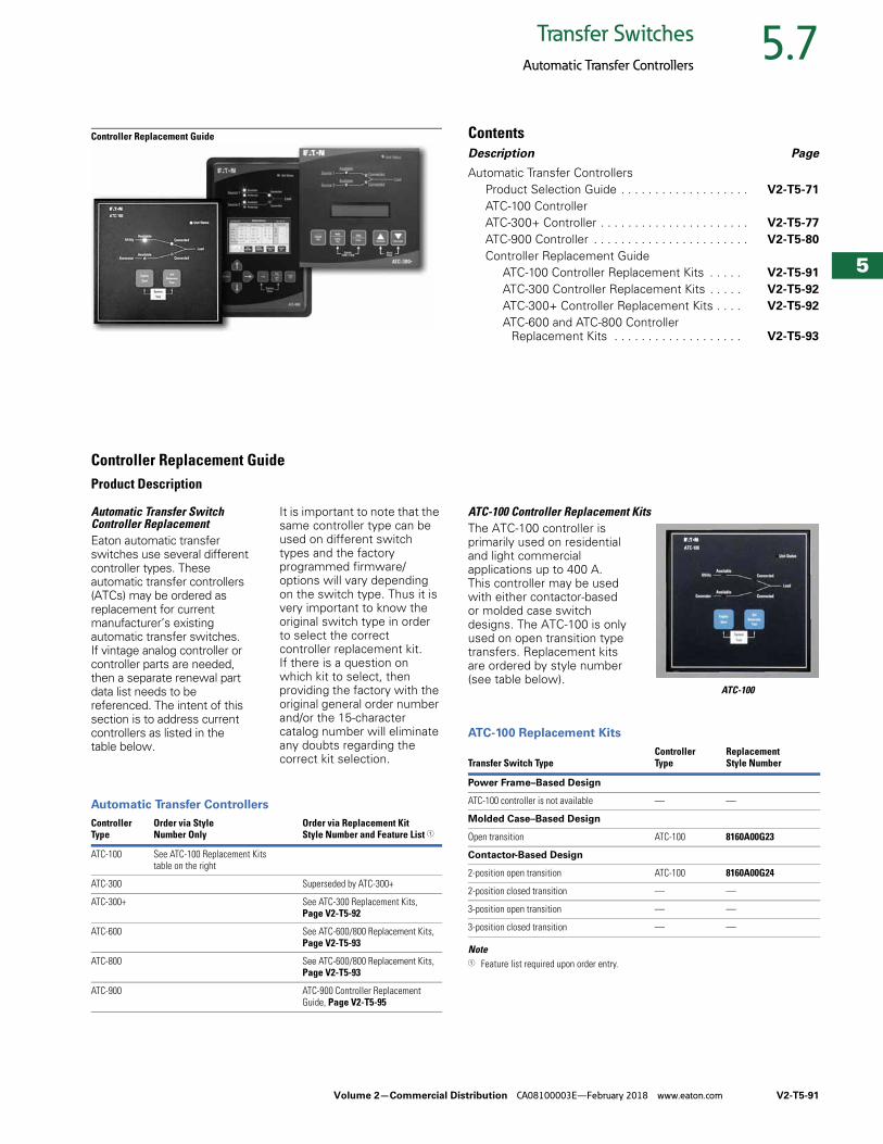
Volume 2—Commercial Distribution CA08100003E—February 2018 www.eaton.com V2-T5-91
5
5
5
5
5
5
5
5
5
5
5
5
5
5
5
5
5
5
5
5
5
5
5
5
5
5
5
5
5
5
5.7Transfer Switches
Automatic Transfer Controllers
Controller Replacement Guide ContentsDescription Page
Automatic Transfer ControllersProduct Selection Guide . . . . . . . . . . . . . . . . . . . V2-T5-71
ATC-100 ControllerATC-300+ Controller . . . . . . . . . . . . . . . . . . . . . . V2-T5-77
ATC-900 Controller . . . . . . . . . . . . . . . . . . . . . . . V2-T5-80
Controller Replacement GuideATC-100 Controller Replacement Kits . . . . . V2-T5-91
ATC-300 Controller Replacement Kits . . . . . V2-T5-92
ATC-300+ Controller Replacement Kits . . . . V2-T5-92
ATC-600 and ATC-800 Controller Replacement Kits . . . . . . . . . . . . . . . . . . . V2-T5-93
Controller Replacement GuideProduct Description
Automatic Transfer Switch Controller ReplacementEaton automatic transfer switches use several different controller types. These automatic transfer controllers (ATCs) may be ordered as replacement for current manufacturer’s existing automatic transfer switches. If vintage analog controller or controller parts are needed, then a separate renewal part data list needs to be referenced. The intent of this section is to address current controllers as listed in the table below.
It is important to note that the same controller type can be used on different switch types and the factory programmed firmware/options will vary depending on the switch type. Thus it is very important to know the original switch type in order to select the correct controller replacement kit. If there is a question on which kit to select, then providing the factory with the original general order number and/or the 15-character catalog number will eliminate any doubts regarding the correct kit selection.
Automatic Transfer Controllers
Controller Type
Order via StyleNumber Only
Order via Replacement Kit Style Number and Feature List 1
ATC-100 See ATC-100 Replacement Kits table on the right
ATC-300 Superseded by ATC-300+
ATC-300+ See ATC-300 Replacement Kits,Page V2-T5-92
ATC-600 See ATC-600/800 Replacement Kits,Page V2-T5-93
ATC-800 See ATC-600/800 Replacement Kits,Page V2-T5-93
ATC-900 ATC-900 Controller Replacement Guide, Page V2-T5-95
ATC-100 Controller Replacement KitsThe ATC-100 controller is primarily used on residential and light commercial applications up to 400 A. This controller may be used with either contactor-based or molded case switch designs. The ATC-100 is only used on open transition type transfers. Replacement kits are ordered by style number (see table below).
ATC-100
ATC-100 Replacement Kits
Note1 Feature list required upon order entry.
Transfer Switch TypeController Type
Replacement Style Number
Power Frame–Based Design
ATC-100 controller is not available — —
Molded Case–Based Design
Open transition ATC-100 8160A00G23
Contactor-Based Design
2-position open transition ATC-100 8160A00G24
2-position closed transition — —
3-position open transition — —
3-position closed transition — —
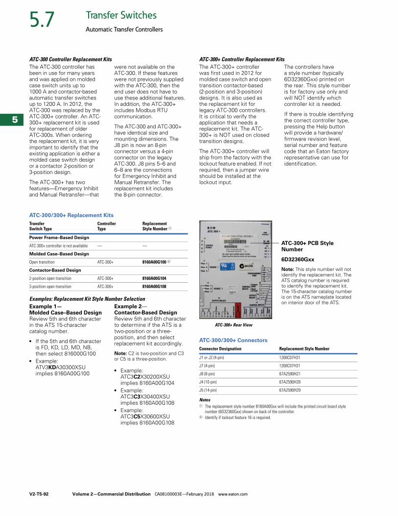
V2-T5-92 Volume 2—Commercial Distribution CA08100003E—February 2018 www.eaton.com
5
5
5
5
5
5
5
5
5
5
5
5
5
5
5
5
5
5
5
5
5
5
5
5
5
5
5
5
5
5
5.7 Transfer Switches
Automatic Transfer Controllers
ATC-300 Controller Replacement Kits The ATC-300 controller has been in use for many years and was applied on molded case switch units up to 1000 A and contactor-based automatic transfer switches up to 1200 A. In 2012, the ATC-300 was replaced by the ATC-300+ controller. An ATC-300+ replacement kit is used for replacement of older ATC-300s. When ordering the replacement kit, it is very important to identify that the existing application is either a molded case switch design or a contactor 2-position or 3-position design.
The ATC-300+ has two features—Emergency Inhibit and Manual Retransfer—that
were not available on the ATC-300. If these features were not previously supplied with the ATC-300, then the end user does not have to use these additional features. In addition, the ATC-300+ includes Modbus RTU communication.
The ATC-300 and ATC-300+ have identical size and mounting dimensions. The J8 pin is now an 8-pin connector versus a 4-pin connector on the legacy ATC-300. J8 pins 5–6 and 6–8 are the connections for Emergency Inhibit and Manual Retransfer. The replacement kit includes the 8-pin connector.
ATC-300/300+ Replacement Kits
Examples: Replacement Kit Style Number SelectionExample 1—Molded Case–Based DesignReview 5th and 6th character in the ATS 15-character catalog number.
● If the 5th and 6th character is FD, KD, LD, MD, NB, then select 816000G100
● Example: ATV3KDA30300XSU implies 8160A00G100
Example 2—Contactor-Based Design Review 5th and 6th character to determine if the ATS is a two-position or a three-position, and then select replacement kit accordingly.
Note: C2 is two-position and C3 or C5 is a three-position.
● Example:ATC3C2X30200XSU implies 8160A00G104
● Example:ATC3C3X30400XSU implies 8160A00G108
● Example:ATC3C5X30600XSU implies 8160A00G108
Transfer Switch Type
Controller Type
Replacement Style Number 1
Power Frame–Based Design
ATC-300+ controller is not available — —
Molded Case–Based Design
Open transition ATC-300+ 8160A00G100 2
Contactor-Based Design
2-position open transition ATC-300+ 8160A00G104
3-position open transition ATC-300+ 8160A00G108
ATC-300+ Controller Replacement Kits The ATC-300+ controller was first used in 2012 for molded case switch and open transition contactor-based (2-position and 3-position) designs. It is also used as the replacement kit for legacy ATC-300 controllers. It is critical to verify the application that needs a replacement kit. The ATC-300+ is NOT used on closed transition designs.
The ATC-300+ controller will ship from the factory with the lockout feature enabled. If not required, then a jumper wire should be installed at the lockout input.
The controllers have a style number (typically 6D32360Gxx) printed on the rear. This style number is for factory use only and will NOT identify which controller kit is needed.
If there is trouble identifying the correct controller type, pressing the Help button will provide a hardware/firmware revision level, serial number and feature code that an Eaton factory representative can use for identification.
ATC-300+ Rear View
ATC-300/300+ Connectors
Notes1 The replacement style number 8160A00Gxx will include the printed circuit board style
number (6D32360Gxx) shown on back of the controller.2 Identify if lockout feature 16 is required.
Connector Designation Replacement Style Number
J1 or J2 (4-pin) 1268C07H31
J7 (4-pin) 1268C07H31
J8 (8-pin) 67A2590H21
J4 (10-pin) 67A2590H28
J5 (14-pin) 67A2590H29
ATC-300+ PCB Style Number
6D32360Gxx
Note: This style number will not identify the replacement kit. The ATS catalog number is required to identify the replacement kit. The 15-character catalog number is on the ATS nameplate located on interior door of the ATS.
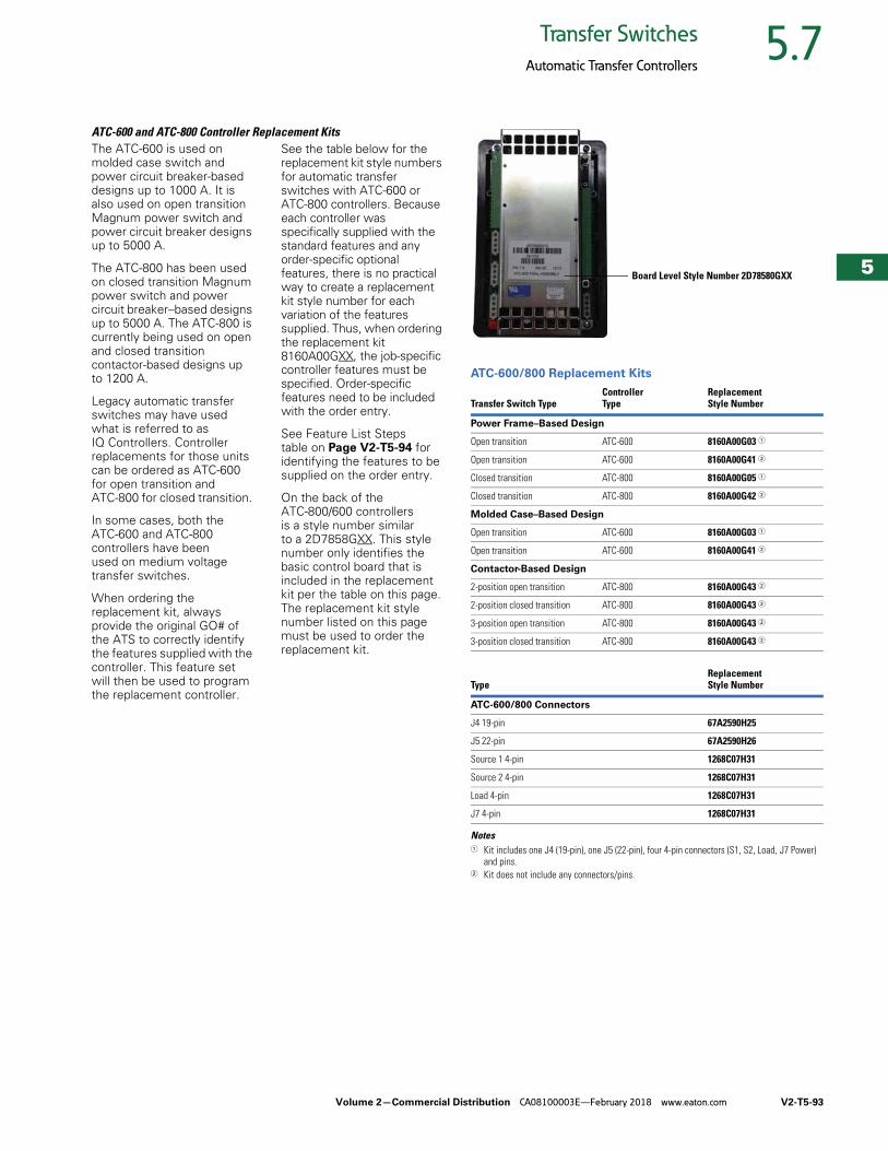
Volume 2—Commercial Distribution CA08100003E—February 2018 www.eaton.com V2-T5-93
5
5
5
5
5
5
5
5
5
5
5
5
5
5
5
5
5
5
5
5
5
5
5
5
5
5
5
5
5
5
5.7Transfer Switches
Automatic Transfer Controllers
ATC-600 and ATC-800 Controller Replacement Kits The ATC-600 is used on molded case switch and power circuit breaker-based designs up to 1000 A. It is also used on open transition Magnum power switch and power circuit breaker designs up to 5000 A.
The ATC-800 has been used on closed transition Magnum power switch and power circuit breaker–based designs up to 5000 A. The ATC-800 is currently being used on open and closed transition contactor-based designs up to 1200 A.
Legacy automatic transfer switches may have used what is referred to as IQ Controllers. Controller replacements for those units can be ordered as ATC-600 for open transition and ATC-800 for closed transition.
In some cases, both the ATC-600 and ATC-800 controllers have been used on medium voltage transfer switches.
When ordering the replacement kit, always provide the original GO# of the ATS to correctly identify the features supplied with the controller. This feature set will then be used to program the replacement controller.
See the table below for the replacement kit style numbers for automatic transfer switches with ATC-600 or ATC-800 controllers. Because each controller was specifically supplied with the standard features and any order-specific optional features, there is no practical way to create a replacement kit style number for each variation of the features supplied. Thus, when ordering the replacement kit 8160A00GXX, the job-specific controller features must be specified. Order-specific features need to be included with the order entry.
See Feature List Steps table on Page V2-T5-94 for identifying the features to be supplied on the order entry.
On the back of the ATC-800/600 controllers is a style number similar to a 2D7858GXX. This style number only identifies the basic control board that is included in the replacement kit per the table on this page. The replacement kit style number listed on this page must be used to order the replacement kit.
ATC-600/800 Replacement Kits
Notes1 Kit includes one J4 (19-pin), one J5 (22-pin), four 4-pin connectors (S1, S2, Load, J7 Power)
and pins.2 Kit does not include any connectors/pins.
Transfer Switch TypeController Type
Replacement Style Number
Power Frame–Based Design
Open transition ATC-600 8160A00G03 1
Open transition ATC-600 8160A00G41 2
Closed transition ATC-800 8160A00G05 1
Closed transition ATC-800 8160A00G42 2
Molded Case–Based Design
Open transition ATC-600 8160A00G03 1
Open transition ATC-600 8160A00G41 2
Contactor-Based Design
2-position open transition ATC-800 8160A00G43 2
2-position closed transition ATC-800 8160A00G43 2
3-position open transition ATC-800 8160A00G43 2
3-position closed transition ATC-800 8160A00G43 2
Type Replacement Style Number
ATC-600/800 Connectors
J4 19-pin 67A2590H25
J5 22-pin 67A2590H26
Source 1 4-pin 1268C07H31
Source 2 4-pin 1268C07H31
Load 4-pin 1268C07H31
J7 4-pin 1268C07H31
Board Level Style Number 2D78580GXX
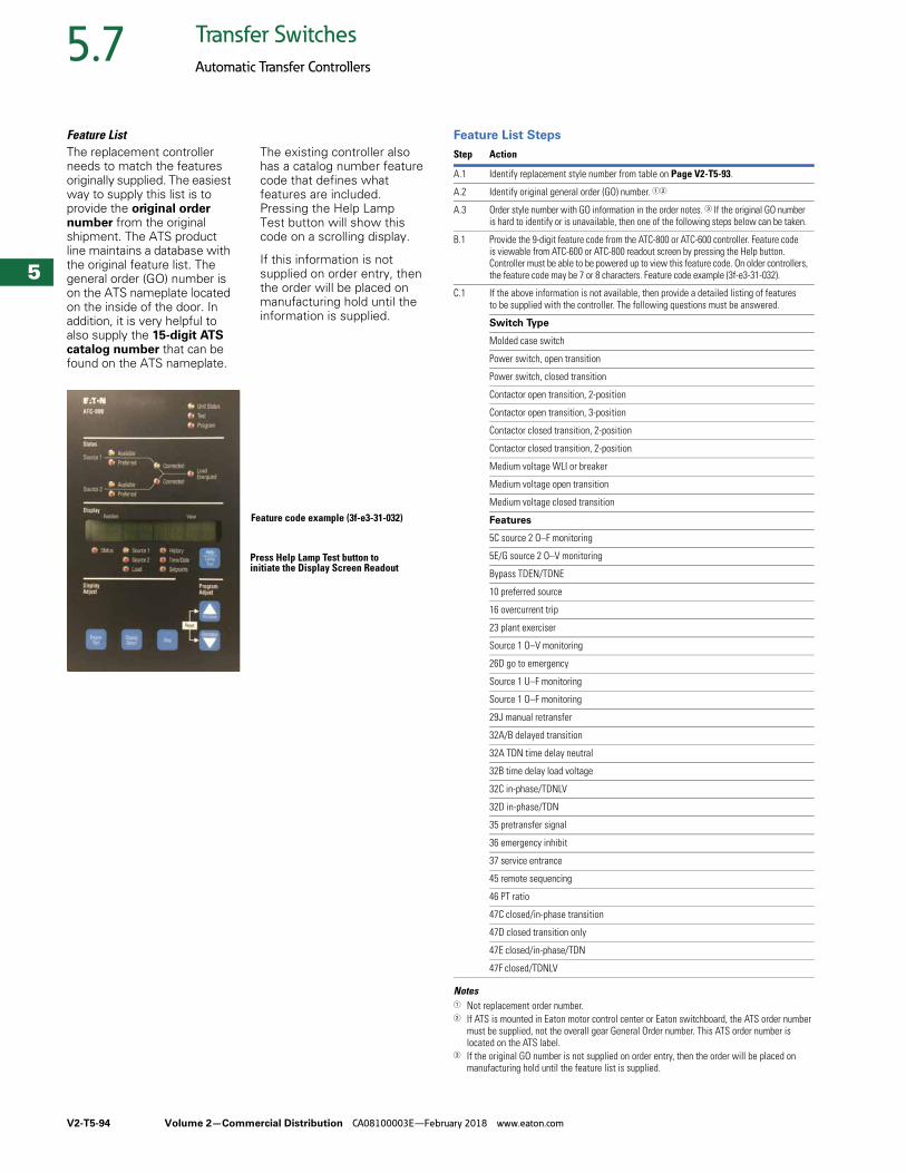
V2-T5-94 Volume 2—Commercial Distribution CA08100003E—February 2018 www.eaton.com
5
5
5
5
5
5
5
5
5
5
5
5
5
5
5
5
5
5
5
5
5
5
5
5
5
5
5
5
5
5
5.7 Transfer Switches
Automatic Transfer Controllers
Feature List The replacement controller needs to match the features originally supplied. The easiest way to supply this list is to provide the original order number from the original shipment. The ATS product line maintains a database with the original feature list. The general order (GO) number is on the ATS nameplate located on the inside of the door. In addition, it is very helpful to also supply the 15-digit ATS catalog number that can be found on the ATS nameplate.
The existing controller also has a catalog number feature code that defines what features are included. Pressing the Help Lamp Test button will show this code on a scrolling display.
If this information is not supplied on order entry, then the order will be placed on manufacturing hold until the information is supplied.
Feature code example (3f-e3-31-032)
Press Help Lamp Test button to initiate the Display Screen Readout
Feature List Steps
Notes1 Not replacement order number.2 If ATS is mounted in Eaton motor control center or Eaton switchboard, the ATS order number
must be supplied, not the overall gear General Order number. This ATS order number is located on the ATS label.
3 If the original GO number is not supplied on order entry, then the order will be placed on manufacturing hold until the feature list is supplied.
Step Action
A.1 Identify replacement style number from table on Page V2-T5-93.
A.2 Identify original general order (GO) number. 12
A.3 Order style number with GO information in the order notes. 3 If the original GO number is hard to identify or is unavailable, then one of the following steps below can be taken.
B.1 Provide the 9-digit feature code from the ATC-800 or ATC-600 controller. Feature code is viewable from ATC-600 or ATC-800 readout screen by pressing the Help button. Controller must be able to be powered up to view this feature code. On older controllers, the feature code may be 7 or 8 characters. Feature code example (3f-e3-31-032).
C.1 If the above information is not available, then provide a detailed listing of features to be supplied with the controller. The following questions must be answered.
Switch Type
Molded case switch
Power switch, open transition
Power switch, closed transition
Contactor open transition, 2-position
Contactor open transition, 3-position
Contactor closed transition, 2-position
Contactor closed transition, 2-position
Medium voltage WLI or breaker
Medium voltage open transition
Medium voltage closed transition
Features
5C source 2 O–F monitoring
5E/G source 2 O–V monitoring
Bypass TDEN/TDNE
10 preferred source
16 overcurrent trip
23 plant exerciser
Source 1 O–V monitoring
26D go to emergency
Source 1 U–F monitoring
Source 1 O–F monitoring
29J manual retransfer
32A/B delayed transition
32A TDN time delay neutral
32B time delay load voltage
32C in-phase/TDNLV
32D in-phase/TDN
35 pretransfer signal
36 emergency inhibit
37 service entrance
45 remote sequencing
46 PT ratio
47C closed/in-phase transition
47D closed transition only
47E closed/in-phase/TDN
47F closed/TDNLV
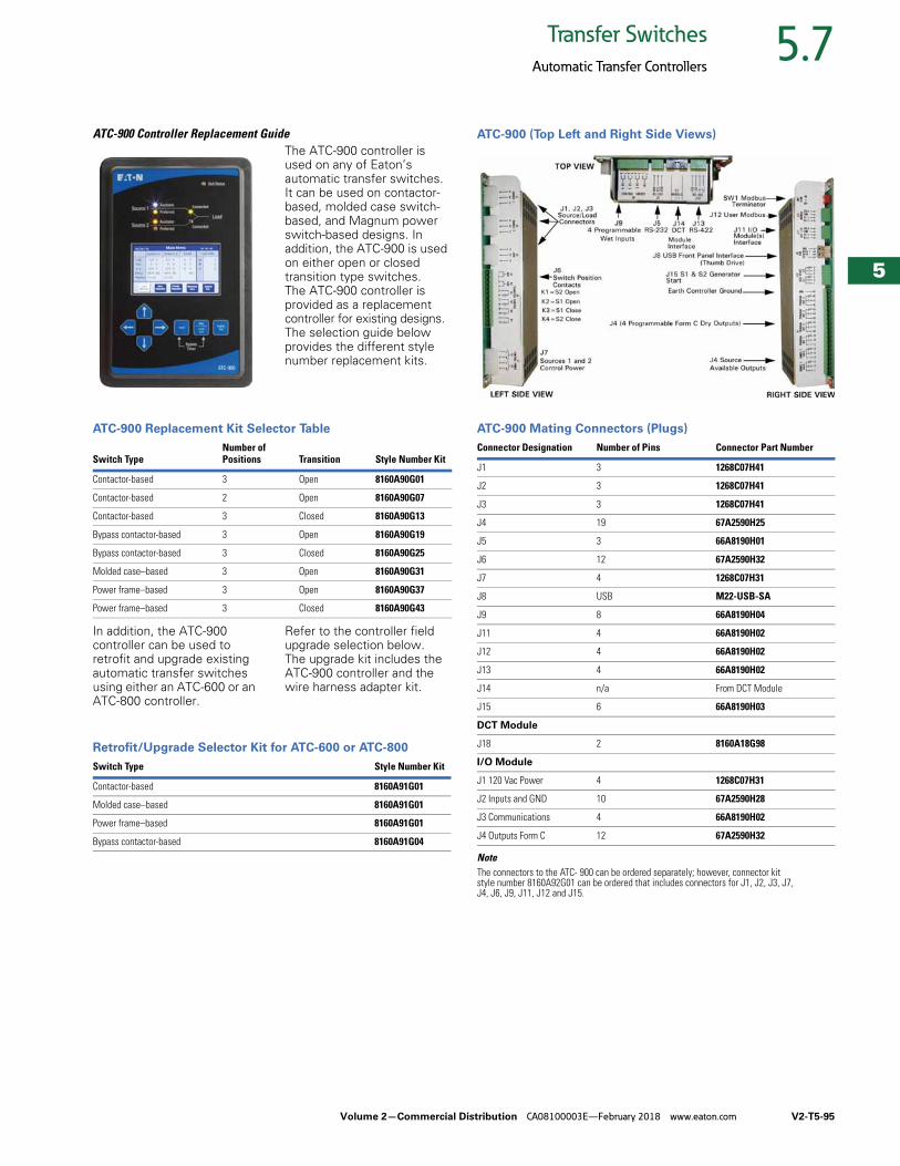
Volume 2—Commercial Distribution CA08100003E—February 2018 www.eaton.com V2-T5-95
5
5
5
5
5
5
5
5
5
5
5
5
5
5
5
5
5
5
5
5
5
5
5
5
5
5
5
5
5
5
5.7Transfer Switches
Automatic Transfer Controllers
ATC-900 Controller Replacement GuideThe ATC-900 controller is used on any of Eaton’s automatic transfer switches. It can be used on contactor-based, molded case switch-based, and Magnum power switch-based designs. In addition, the ATC-900 is used on either open or closed transition type switches. The ATC-900 controller is provided as a replacement controller for existing designs. The selection guide below provides the different style number replacement kits.
ATC-900 Replacement Kit Selector Table
In addition, the ATC-900 controller can be used to retrofit and upgrade existing automatic transfer switches using either an ATC-600 or an ATC-800 controller.
Refer to the controller field upgrade selection below. The upgrade kit includes the ATC-900 controller and the wire harness adapter kit.
Retrofit/Upgrade Selector Kit for ATC-600 or ATC-800
Switch TypeNumber ofPositions Transition Style Number Kit
Contactor-based 3 Open 8160A90G01
Contactor-based 2 Open 8160A90G07
Contactor-based 3 Closed 8160A90G13
Bypass contactor-based 3 Open 8160A90G19
Bypass contactor-based 3 Closed 8160A90G25
Molded case–based 3 Open 8160A90G31
Power frame–based 3 Open 8160A90G37
Power frame–based 3 Closed 8160A90G43
Switch Type Style Number Kit
Contactor-based 8160A91G01
Molded case–based 8160A91G01
Power frame–based 8160A91G01
Bypass contactor-based 8160A91G04
ATC-900 (Top Left and Right Side Views)
ATC-900 Mating Connectors (Plugs)
NoteThe connectors to the ATC- 900 can be ordered separately; however, connector kit style number 8160A92G01 can be ordered that includes connectors for J1, J2, J3, J7, J4, J6, J9, J11, J12 and J15.
Connector Designation Number of Pins Connector Part Number
J1 3 1268C07H41
J2 3 1268C07H41
J3 3 1268C07H41
J4 19 67A2590H25
J5 3 66A8190H01
J6 12 67A2590H32
J7 4 1268C07H31
J8 USB M22-USB-SA
J9 8 66A8190H04
J11 4 66A8190H02
J12 4 66A8190H02
J13 4 66A8190H02
J14 n/a From DCT Module
J15 6 66A8190H03
DCT Module
J18 2 8160A18G98
I/O Module
J1 120 Vac Power 4 1268C07H31
J2 Inputs and GND 10 67A2590H28
J3 Communications 4 66A8190H02
J4 Outputs Form C 12 67A2590H32
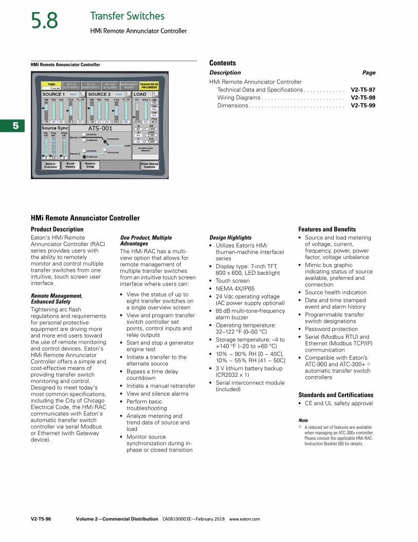
V2-T5-96 Volume 2—Commercial Distribution CA08100003E—February 2018 www.eaton.com
5
5
5
5
5
5
5
5
5
5
5
5
5
5
5
5
5
5
5
5
5
5
5
5
5
5
5
5
5
5
5.8 Transfer Switches
HMi Remote Annunciator Controller
HMi Remote Annunciator Controller ContentsDescription Page
HMi Remote Annunciator ControllerTechnical Data and Specifications . . . . . . . . . . . . . V2-T5-97
Wiring Diagrams . . . . . . . . . . . . . . . . . . . . . . . . . . V2-T5-98
Dimensions. . . . . . . . . . . . . . . . . . . . . . . . . . . . . . V2-T5-99
HMi Remote Annunciator ControllerProduct DescriptionEaton’s HMi Remote Annunciator Controller (RAC) series provides users with the ability to remotely monitor and control multiple transfer switches from one intuitive, touch screen user interface.
Remote Management, Enhanced SafetyTightening arc flash regulations and requirements for personal protective equipment are driving more and more end users toward the use of remote monitoring and control devices. Eaton’s HMi Remote Annunciator Controller offers a simple and cost-effective means of providing transfer switch monitoring and control. Designed to meet today’s most common specifications, including the City of Chicago Electrical Code, the HMi RAC communicates with Eaton’s automatic transfer switch controller via serial Modbus or Ethernet (with Gateway device).
One Product, Multiple AdvantagesThe HMi RAC has a multi-view option that allows for remote management of multiple transfer switches from an intuitive touch screen interface where users can:
● View the status of up to eight transfer switches on a single overview screen
● View and program transfer switch controller set points, control inputs and relay outputs
● Start and stop a generator engine test
● Initiate a transfer to the alternate source
● Bypass a time delay countdown
● Initiate a manual retransfer● View and silence alarms● Perform basic
troubleshooting● Analyze metering and
trend data of source and load
● Monitor source synchronization during in-phase or closed transition
Design Highlights● Utilizes Eaton’s HMi
(human-machine interface) series
● Display type: 7-inch TFT, 800 x 600, LED backlight
● Touch screen● NEMA 4X/IP65● 24 Vdc operating voltage
(AC power supply optional)● 85 dB multi-tone-frequency
alarm buzzer● Operating temperature:
32–122 °F (0–50 °C)● Storage temperature: –4 to
+140 °F (–20 to +60 °C)● 10% ~ 90% RH [0 ~ 40C],
10% ~ 55% RH [41 ~ 50C]● 3 V lithium battery backup
(CR2032 x 1)● Serial interconnect module
(included)
Features and Benefits● Source and load metering
of voltage, current, frequency, power, power factor, voltage unbalance
● Mimic bus graphic indicating status of source available, preferred and connection
● Source health indication● Date and time stamped
event and alarm history● Programmable transfer
switch designations● Password protection● Serial (Modbus RTU) and
Ethernet (Modbus TCP/IP) communication
● Compatible with Eaton’s ATC-900 and ATC-300+ 1 automatic transfer switch controllers
Standards and Certifications● CE and UL safety approval
Note1 A reduced set of features are available
when managing an ATC-300+ controller. Please consult the applicable HMi RAC Instruction Booklet (IB) for details.
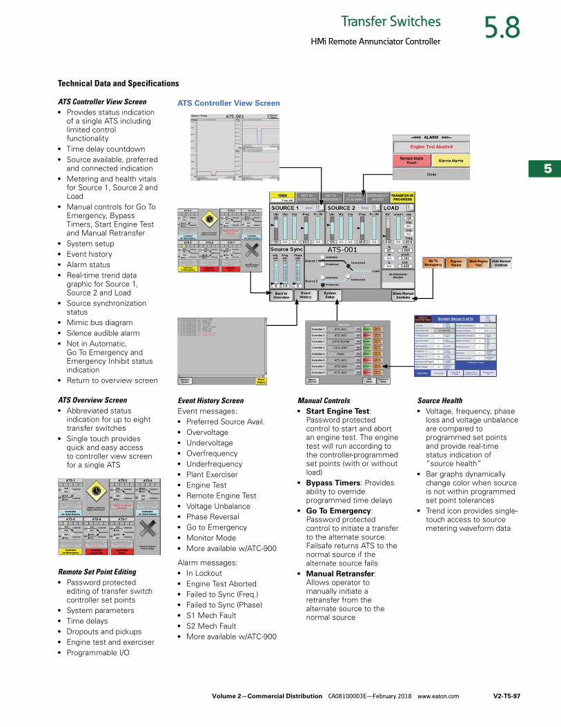
Volume 2—Commercial Distribution CA08100003E—February 2018 www.eaton.com V2-T5-97
5
5
5
5
5
5
5
5
5
5
5
5
5
5
5
5
5
5
5
5
5
5
5
5
5
5
5
5
5
5
5.8Transfer Switches
HMi Remote Annunciator Controller
ATS Controller View Screen● Provides status indication
of a single ATS including limited control functionality
● Time delay countdown● Source available, preferred
and connected indication● Metering and health vitals
for Source 1, Source 2 and Load
● Manual controls for Go To Emergency, Bypass Timers, Start Engine Test and Manual Retransfer
● System setup● Event history● Alarm status● Real-time trend data
graphic for Source 1, Source 2 and Load
● Source synchronization status
● Mimic bus diagram● Silence audible alarm● Not in Automatic,
Go To Emergency and Emergency Inhibit status indication
● Return to overview screen
ATS Overview Screen● Abbreviated status
indication for up to eight transfer switches
● Single touch provides quick and easy access to controller view screen for a single ATS
Remote Set Point Editing● Password protected
editing of transfer switch controller set points
● System parameters● Time delays● Dropouts and pickups● Engine test and exerciser● Programmable I/O
Technical Data and Specifications
ATS Controller View Screen
Event History ScreenEvent messages:● Preferred Source Avail.● Overvoltage● Undervoltage● Overfrequency● Underfrequency● Plant Exerciser● Engine Test● Remote Engine Test● Voltage Unbalance● Phase Reversal● Go to Emergency● Monitor Mode● More available w/ATC-900
Alarm messages:● In Lockout● Engine Test Aborted● Failed to Sync (Freq.)● Failed to Sync (Phase)● S1 Mech Fault● S2 Mech Fault● More available w/ATC-900
Manual Controls● Start Engine Test:
Password protected control to start and abort an engine test. The engine test will run according to the controller-programmed set points (with or without load)
● Bypass Timers: Provides ability to override programmed time delays
● Go To Emergency: Password protected control to initiate a transfer to the alternate source. Failsafe returns ATS to the normal source if the alternate source fails
● Manual Retransfer: Allows operator to manually initiate a retransfer from the alternate source to the normal source
Source Health● Voltage, frequency, phase
loss and voltage unbalance are compared to programmed set points and provide real-time status indication of “source health”
● Bar graphs dynamically change color when source is not within programmed set point tolerances
● Trend icon provides single-touch access to source metering waveform data
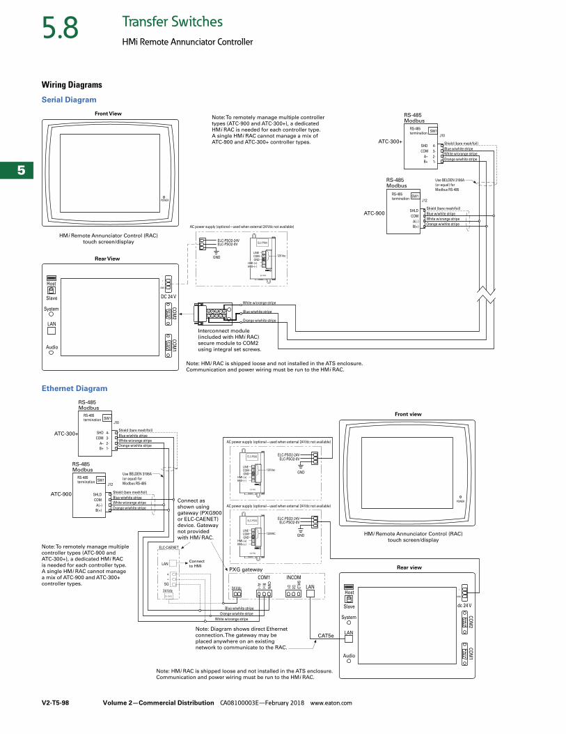
V2-T5-98 Volume 2—Commercial Distribution CA08100003E—February 2018 www.eaton.com
5
5
5
5
5
5
5
5
5
5
5
5
5
5
5
5
5
5
5
5
5
5
5
5
5
5
5
5
5
5
5.8 Transfer Switches
HMi Remote Annunciator Controller
Wiring Diagrams
Serial Diagram
Ethernet Diagram
ELC-PS02
120 Vac
B+ 1-
A– 2-
COM 3-
SHD 4-
J10
RS-485Modbus
ATC-300+
GND
10 9 8 7 6
1 2 3 4 5
HMi Remote Annunciator Control (RAC)
touch screen/display
Orange w/white stripe
White w/orange stripe
Blue w/white stripe
Shield (bare mesh/foil)
White w/orange stripe
Blue w/white stripe
Orange w/white stripe
B(+)
A(–)
COM
SHLD
J12
RS-485Modbus
ATC-900
Orange w/white stripe
White w/orange stripe
Blue w/white stripe
Shield (bare mesh/foil)
Front View
Rear View
Note: To remotely manage multiple controller
types (ATC-900 and ATC-300+), a dedicated
HMi RAC is needed for each controller type.
A single HMi RAC cannot manage a mix of
ATC-900 and ATC-300+ controller types.
ELC-PS02
LINECOMGND
HMI–(+)HMI–(–)
ELC-PSO2-24VELC-PSO2-0V
SW1
Interconnect module
(included with HMi RAC)
secure module to COM2
using integral set screws.
L
N
24 V
0 V
+
–
GND
POWER
CO
M2
CO
M1
DC 24 VSlave
Host
System
LAN
Audio
Use BELDEN 3106A
(or equal) for
Modbus RS-485
SW1RS-485termination
Note: HMi RAC is shipped loose and not installed in the ATS enclosure.
Communication and power wiring must be run to the HMi RAC.
RS-485termination
AC power supply (optional—used when external 24 Vdc not available)
ELC-PS02
120VACGND
ELC-PS02
120 VacGND
PXG gateway
SH
LDD2
D1
CM
N
B(+
)
A(–)
White w/orange stripe
Orange w/white stripe
Blue w/white stripe
Orange w/white stripe
White w/orange stripe
Blue w/white stripe
Shield (bare mesh/foil)
+
–
SG
ELC-CAENET
B(+)
A(–)
COM
SHLD
J12
RS-485Modbus
ATC-900
Orange w/white stripe
White w/orange stripe
Blue w/white stripe
Shield (bare mesh/foil)
B+ 1-
A– 2-
COM 3-
SHD 4-
RS-485Modbus
ATC-300+
J10
Connect
to HMi
Note: To remotely manage multiple
controller types (ATC-900 and
ATC-300+), a dedicated HMi RAC
is needed for each controller type.
A single HMi RAC cannot manage
a mix of ATC-900 and ATC-300+
controller types.
ELC-PS02
LINECOMGND
HMI–(+)HMI–(–)
CO
M2
CO
M1
Slave
Host
System
ELC-PSO2-24VELC-PSO2-0V
L
N
24 V
0 V
LAN
Audio
ELC-PS02
LINECOMGND
HMI–(+)HMI–(–)
ELC-PSO2-24VELC-PSO2-0V
L
N
24 V
0 V
INCOM
LAN
CAT5e
24 Vdc
Note: Diagram shows direct Ethernet
connection. The gateway may be
placed anywhere on an existing
network to communicate to the RAC.
COM1
LAN
SW1
SW1RS-485termination
24 Vdc
Connect as
shown using
gateway (PXG900
or ELC-CAENET)
device. Gateway
not provided
with HMi RAC.
AC power supply (optional—used when external 24 Vdc not available)
AC power supply (optional—used when external 24 Vdc not available)
+
–
GND
dc 24 V
RS-485termination
Use BELDEN 3106A
(or equal) for
Modbus RS-485
HMi Remote Annunciator Control (RAC)
touch screen/display
Front view
Rear view
POWER
Note: HMi RAC is shipped loose and not installed in the ATS enclosure.
Communication and power wiring must be run to the HMi RAC.
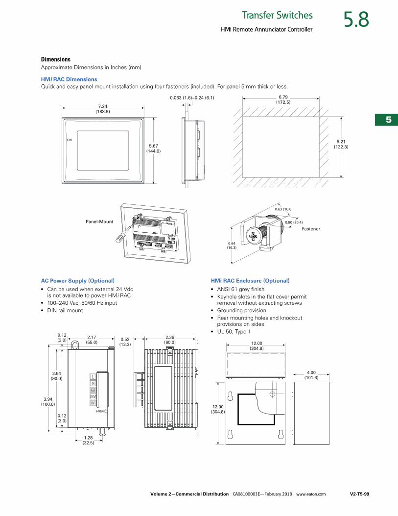
Volume 2—Commercial Distribution CA08100003E—February 2018 www.eaton.com V2-T5-99
5
5
5
5
5
5
5
5
5
5
5
5
5
5
5
5
5
5
5
5
5
5
5
5
5
5
5
5
5
5
5.8Transfer Switches
HMi Remote Annunciator Controller
DimensionsApproximate Dimensions in Inches (mm)
HMi RAC Dimensions
Quick and easy panel-mount installation using four fasteners (included). For panel 5 mm thick or less.
AC Power Supply (Optional)
● Can be used when external 24 Vdc is not available to power HMi RAC
● 100–240 Vac, 50/60 Hz input● DIN rail mount
HMi RAC Enclosure (Optional)
● ANSI 61 grey finish● Keyhole slots in the flat cover permit
removal without extracting screws● Grounding provision● Rear mounting holes and knockout
provisions on sides● UL 50, Type 1
7.24(183.9)
6.79(172.5)
0.063 (1.6)~0.24 (6.1)
5.67(144.0)
5.21(132.3)
Panel-Mount
Fastener
0.63 (16.0)
0.80 (20.4)
0.64(16.3)
2.17(55.0)
0.52(13.3)
2.36(60.0)
1.28(32.5)
0.12(3.0)
0.12(3.0)
3.54(90.0)
3.94(100.0)
12.00(304.8)
4.00(101.6)
12.00(304.8)
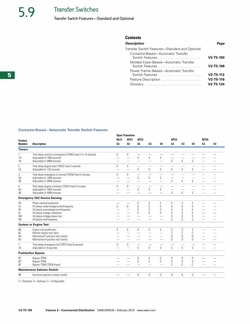
V2-T5-100 Volume 2—Commercial Distribution CA08100003E—February 2018 www.eaton.com
5
5
5
5
5
5
5
5
5
5
5
5
5
5
5
5
5
5
5
5
5
5
5
5
5
5
5
5
5
5
5.9 Transfer Switches
Transfer Switch Features—Standard and Optional
ContentsDescription Page
Transfer Switch Features—Standard and OptionalContactor-Based—Automatic Transfer
Switch Features . . . . . . . . . . . . . . . . . . . . . . . V2-T5-100
Molded Case–Based—Automatic Transfer Switch Features . . . . . . . . . . . . . . . . . . . . . . . V2-T5-108
Power Frame–Based—Automatic Transfer Switch Features . . . . . . . . . . . . . . . . . . . . . . . V2-T5-112
Feature Description . . . . . . . . . . . . . . . . . . . . . V2-T5-116
Glossary . . . . . . . . . . . . . . . . . . . . . . . . . . . . . . V2-T5-124
Contactor-Based—Automatic Transfer Switch Features
S = Standard, O = Optional, C = Configurable
FeatureNumber Description
Open TransitionRLC1 ATC1 ATC3 ATC9 NTCEC2 C2 C2 C3 C5 C2 C3 C5 C2 C3
Timers
11A1B
Time delay normal to emergency (TDNE) fixed 2 or 15 secondsAdjustable 0–1800 secondsAdjustable 0–9999 minutes
S——
S——
—S—
—S—
—S—
——S
——S
——S
———
———
22A
Time delay engine start (TDES) fixed 3 secondsAdjustable 0–120 seconds
S—
S—
—S
—S
—S
—S
—S
—S
——
——
33A3B
Time delay emergency to normal (TDEN) fixed 5 minutesAdjustable 0–1800 secondsAdjustable 0–9999 minutes
S——
S——
—S—
—S—
—S—
——S
——S
——S
———
———
44A4B
Time delay engine cooldown (TDEC) fixed 5 minutesAdjustable 0–1800 secondsAdjustable 0–9999 minutes
S——
S——
—S—
—S—
—S—
——S
——S
——S
———
———
Emergency (S2) Source Sensing
5H5J5K5L5M5N
Phase reversal protectionAll phase undervoltage/underfrequencyAll phase overvoltage/overfrequencyAll phase voltage unbalanceAll phase voltage phase lossAll phase overfrequency
—S————
—S————
SSSS——
SSSS——
SSSS——
SSSSSS
SSSSSS
SSSSSS
——————
——————
System or Engine Test
6B6C6D6H
Engine test pushbuttonRemote engine test inputMaintained 2-position test switchMaintained 4-position test switch
S———
S———
S———
S———
S———
SCOO
SCOO
SCOO
————
————
77A
Time delay emergency fail (TDEF) fixed 6 secondsAdjustable 0–6 seconds
S—
S—
—S
—S
—S
—S
—S
—S
——
——
Pushbutton Bypass
8C8D8E
Bypass TDENBypass TDNEBypass TDNE/TDEN (input)
———
———
SS—
SS—
SS—
SSC
SSC
SSC
———
———
Maintenance Selector Switch
9B Electrical operator isolator switch — — O O O O O O — —
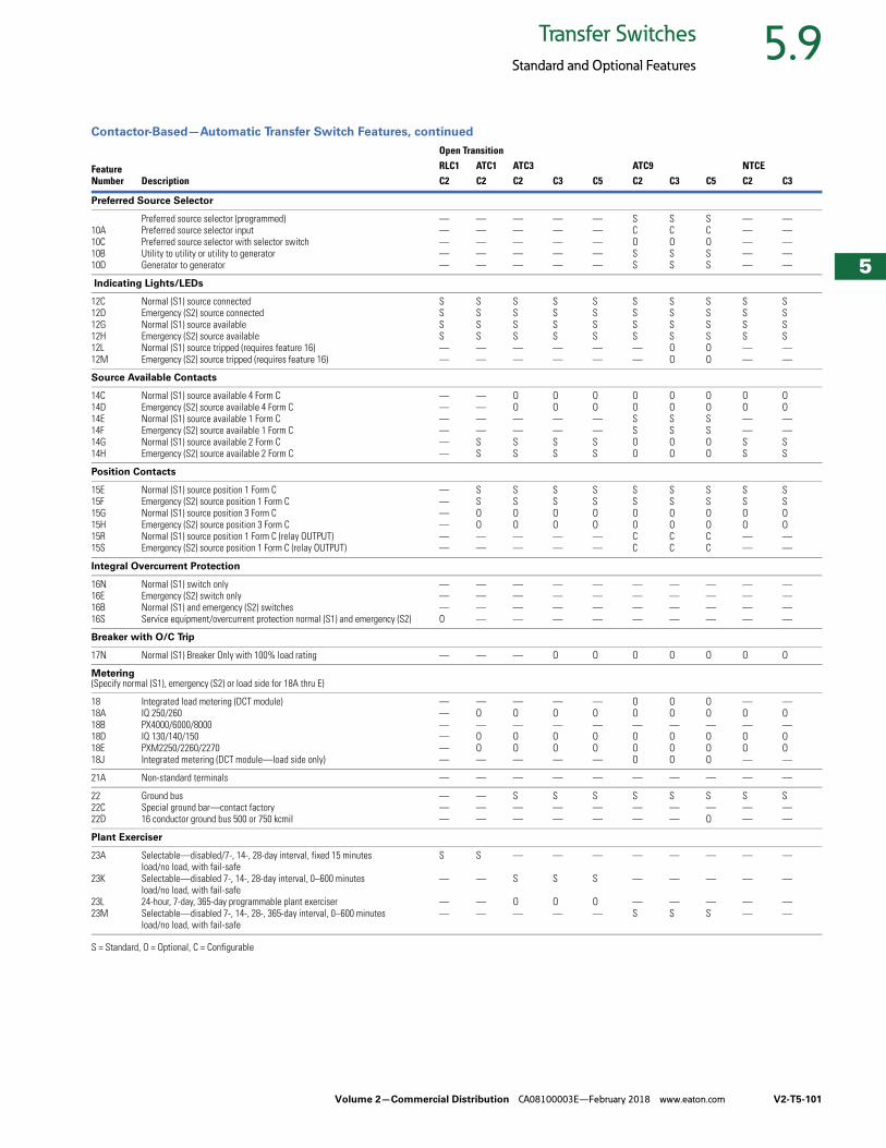
Volume 2—Commercial Distribution CA08100003E—February 2018 www.eaton.com V2-T5-101
5
5
5
5
5
5
5
5
5
5
5
5
5
5
5
5
5
5
5
5
5
5
5
5
5
5
5
5
5
5
5.9Transfer Switches
Standard and Optional Features
Contactor-Based—Automatic Transfer Switch Features, continued
S = Standard, O = Optional, C = Configurable
FeatureNumber Description
Open TransitionRLC1 ATC1 ATC3 ATC9 NTCEC2 C2 C2 C3 C5 C2 C3 C5 C2 C3
Preferred Source Selector
10A10C10B10D
Preferred source selector (programmed)Preferred source selector inputPreferred source selector with selector switchUtility to utility or utility to generatorGenerator to generator
—————
—————
—————
—————
—————
SCOSS
SCOSS
SCOSS
—————
—————
Indicating Lights/LEDs
12C12D12G12H12L12M
Normal (S1) source connectedEmergency (S2) source connectedNormal (S1) source availableEmergency (S2) source availableNormal (S1) source tripped (requires feature 16)Emergency (S2) source tripped (requires feature 16)
SSSS——
SSSS——
SSSS——
SSSS——
SSSS——
SSSS——
SSSSOO
SSSSOO
SSSS——
SSSS——
Source Available Contacts
14C14D14E14F14G14H
Normal (S1) source available 4 Form CEmergency (S2) source available 4 Form CNormal (S1) source available 1 Form CEmergency (S2) source available 1 Form CNormal (S1) source available 2 Form CEmergency (S2) source available 2 Form C
——————
————SS
OO——SS
OO——SS
OO——SS
OOSSOO
OOSSOO
OOSSOO
OO——SS
OO——SS
Position Contacts
15E15F15G15H15R15S
Normal (S1) source position 1 Form CEmergency (S2) source position 1 Form CNormal (S1) source position 3 Form CEmergency (S2) source position 3 Form CNormal (S1) source position 1 Form C (relay OUTPUT)Emergency (S2) source position 1 Form C (relay OUTPUT)
——————
SSOO——
SSOO——
SSOO——
SSOO——
SSOOCC
SSOOCC
SSOOCC
SSOO——
SSOO——
Integral Overcurrent Protection
16N16E16B16S
Normal (S1) switch onlyEmergency (S2) switch onlyNormal (S1) and emergency (S2) switchesService equipment/overcurrent protection normal (S1) and emergency (S2)
———O
————
————
————
————
————
————
————
————
————
Breaker with O/C Trip
17N Normal (S1) Breaker Only with 100% load rating — — — O O O O O O O
Metering(Specify normal (S1), emergency (S2) or load side for 18A thru E)
1818A18B18D18E18J
Integrated load metering (DCT module)IQ 250/260PX4000/6000/8000IQ 130/140/150PXM2250/2260/2270Integrated metering (DCT module—load side only)
——————
—O—OO—
—O—OO—
—O—OO—
—O—OO—
OO—OOO
OO—OOO
OO—OOO
—O—OO—
—O—OO—
21A Non-standard terminals — — — — — — — — — —
2222C22D
Ground busSpecial ground bar—contact factory16 conductor ground bus 500 or 750 kcmil
———
———
S——
S——
S——
S——
S——
S—O
S——
S——
Plant Exerciser
23A
23K
23L23M
Selectable—disabled/7-, 14-, 28-day interval, fixed 15 minutesload/no load, with fail-safeSelectable—disabled 7-, 14-, 28-day interval, 0–600 minutesload/no load, with fail-safe24-hour, 7-day, 365-day programmable plant exerciserSelectable—disabled 7-, 14-, 28-, 365-day interval, 0–600 minutesload/no load, with fail-safe
S
—
——
S
—
——
—
S
O—
—
S
O—
—
S
O—
—
—
—S
—
—
—S
—
—
—S
—
—
——
—
—
——

V2-T5-102 Volume 2—Commercial Distribution CA08100003E—February 2018 www.eaton.com
5
5
5
5
5
5
5
5
5
5
5
5
5
5
5
5
5
5
5
5
5
5
5
5
5
5
5
5
5
5
5.9 Transfer Switches
Standard and Optional Features
Contactor-Based—Automatic Transfer Switch Features, continued
S = Standard, O = Optional, C = Configurable
Note1 When these options are selected with the ATC-900 controller, the associated input or output will be factory fixed and cannot be reconfigured by the user.
FeatureNumber Description
Open TransitionRLC1 ATC1 ATC3 ATC9 NTCEC2 C2 C2 C3 C5 C2 C3 C5 C2 C3
Normal (S1) Source Sensing
26D26E26H26J26K26L26M26P
Go to emergency (S2) inputGo to emergency (S2) input with selector switch 1Phase reversal protectionAll phase undervoltage/underfrequencyAll phase overvoltage/overfrequencyAll phase voltage unbalanceAll phase voltage phase lossAll phase undervoltage
———————S
———————S
S—SSSS——
S—SSSS——
S—SSSS——
C—OSSOS—
COSSSSS—
COSSSSS—
————————
————————
Alternative Transfer Modes of Operation
29G29J29L29M29K
Selector switch for auto or non-auto operation 1Manual (pushbutton) transfer E to N; automatic N to E 1
Manual retransfer on/off inputManual retransfer on/off input with selector switch 1Manual retransfer input
—————
—————
OO———
OO———
OO———
OOCOC
OOCOC
OOCOC
—————
—————
Open Transfer Operation Modes
32A32B32C32D32E32F32G
Time delay neutral adjustable 0–120 seconds (delayed transition)Load voltage decay adjustable 2–30% nominal voltageIn-phase transition defaults to load voltage decayIn-phase transition defaults to time delay neutralDelay transition timer adjustable 3–60 secondsIn-phase transitionTime delay neutral fixed 0 or 2 seconds (delayed transition)
—————S—
—————S—
—————S—
S——————
———S———
—————S—
CCC————
CCC————
———————
———————
Logic Extender Cable (Open Enclosures Only)
34A34C34E34F
48 inches (1219 mm)96 inches (2438 mm)144 inches (3658 mm)100 inches (2540 mm) (fixed mount only)
————
—O——
—O——
—O——
—O——
————
————
————
—O——
—O——
35A35B
Pre-transfer signal contacts 1 Form CPre-/post-transfer signal
——
——
S—
S—
S—
CC
CC
CC
——
——
3636A
Load shed from emergency (S2 inhibit)Load shed—S2 inhibit with keyed switch (INPUT)
——
——
——
S—
S—
CO
CO
CO
——
——
37 Go to “isolated” position (not SE rated) — — — — — C C C — —
Suitable for Use as Service Equipment Requires 16B, N or S
37A Without ground fault protection — — O O O O O O O O
37B With ground fault protection required at 1000 A or more if the electrical service is a solidly grounded wye system of more than 150 V to ground but not exceeding 600 V phase to phase
— — O O O O O O O O
Stainless Steel Device Covers
38A38B
SS cover for device plate or SE disconnectSS cover for controller
——
—O
OO
OO
OO
OO
OO
OO
O—
O—
Space Heater with Thermostat
41A41E
100 watts375 watts
——
O—
O—
O—
O—
O—
O—
O—
O—
O—
42 IBC/CBC seismic qualified S S S S S S S S S S
Load Management Contacts
45A–K45L
Load sequencing contacts (1) Selective load shed (assignable to multiple out put contacts)
——
——
——
——
——
CC
CC
—C
——
——
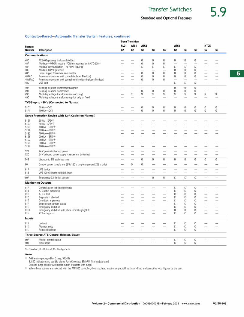
Volume 2—Commercial Distribution CA08100003E—February 2018 www.eaton.com V2-T5-103
5
5
5
5
5
5
5
5
5
5
5
5
5
5
5
5
5
5
5
5
5
5
5
5
5
5
5
5
5
5
5.9Transfer Switches
Standard and Optional Features
Contactor-Based—Automatic Transfer Switch Features, continued
S = Standard, O = Optional, C = Configurable
Notes1 Add feature package B or C (e.g., 51S4B).
B: LED indication and audible alarm, Form C contact, EMI/RFI filtering (standard)C: B and surge counter with Reset button (standard with surge)
2 When these options are selected with the ATC-900 controller, the associated input or output will be factory fixed and cannot be reconfigured by the user.
FeatureNumber Description
Open TransitionRLC1 ATC1 ATC3 ATC9 NTCEC2 C2 C2 C3 C5 C2 C3 C5 C2 C3
Communications
48D48F48F48G48P48RAC48MRAC48U
PXG400 gateway (includes Modbus)Modbus—MPONI module (PONI not required with ATC-300+)Modbus communication—no PONI requiredModbus TCP/IP gatewayPower supply for remote annunciatorRemote annunciator with control (includes Modbus)Remote annunciator with control multi-switch (includes Modbus)USB port
————————
————————
OOS—OOO—
OOS—OOO—
OOS—OOO—
O—SOOO—S
O—SOOO—S
O—SOOO—S
————————
————————
49A49B49C49C
Sensing isolation transformer MagnumSensing isolation transformer Multi-tap voltage transformer (non AG only)Multi-tap voltage transformer (option only on fixed)
————
——S—
—OS—
—OS—
—OS—
OOS—
OOS—
OOS—
——S—
——S—
TVSS up to 480 V (Connected to Normal)
51D151F1
50 kA—CVX100 kA—CVX
——
——
OO
OO
OO
OO
OO
OO
OO
OO
Surge Protection Device with 12 ft Cable (on Normal)
51S151S251S351S451S551S651S751S851S9
50 kA—SPD 180 kA—SPD 1100 kA—SPD 1120 kA—SPD 1160 kA—SPD 1200 kA—SPD 1250 kA—SPD 1300 kA—SPD 1400 kA—SPD 1
—————————
—————————
—————————
—————————
—————————
—————————
—————————
—————————
—————————
—————————
52B52C
24 V generator battery power24 V onboard power supply (charger and batteries)
——
——
——
——
——
——
——
——
——
——
54B Upgrade to 316 stainless steel — — O O O O O O O O
60 Control power transformer (240/120 V single-phase and 208 V only) — O O — — — — — — —
61A61B
UPS deviceUPS 120 Vac terminal block input
——
——
——
——
——
——
——
——
——
——
80A Emergency (S2) inhibit contact — — — O O C C C — —
Monitoring Outputs
81A81B81C81D81E81F81G81GL81H
General alarm indication contactATS not in automaticATS in testEngine test abortedCooldown in processEngine start contact statusEmergency inhibit onEmergency inhibit on with white indicating light 2ATS on bypass
—————————
—————————
—————————
—————————
—————————
CCCCCCCOC
CCCCCCCOC
CCCCCCCOC
—————————
—————————
Inputs
81J81K81L
LockoutMonitor modeRemote load test
———
———
———
———
———
CCC
CCC
CCC
———
———
Three Source ATS Control (Master/Slave)
90A90B
Master control outputSlave input
——
——
——
——
——
CC
CC
CC
——
——
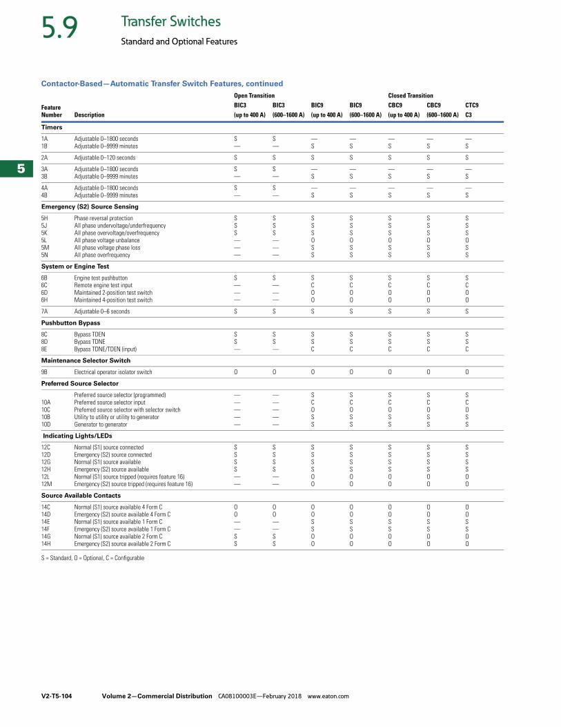
V2-T5-104 Volume 2—Commercial Distribution CA08100003E—February 2018 www.eaton.com
5
5
5
5
5
5
5
5
5
5
5
5
5
5
5
5
5
5
5
5
5
5
5
5
5
5
5
5
5
5
5.9 Transfer Switches
Standard and Optional Features
Contactor-Based—Automatic Transfer Switch Features, continued
S = Standard, O = Optional, C = Configurable
FeatureNumber Description
Open Transition Closed TransitionBIC3 BIC3 BIC9 BIC9 CBC9 CBC9 CTC9(up to 400 A) (600–1600 A) (up to 400 A) (600–1600 A) (up to 400 A) (600–1600 A) C3
Timers
1A1B
Adjustable 0–1800 secondsAdjustable 0–9999 minutes
S—
S—
—S
—S
—S
—S
—S
2A Adjustable 0–120 seconds S S S S S S S
3A3B
Adjustable 0–1800 secondsAdjustable 0–9999 minutes
S—
S—
—S
—S
—S
—S
—S
4A4B
Adjustable 0–1800 secondsAdjustable 0–9999 minutes
S—
S—
—S
—S
—S
—S
—S
Emergency (S2) Source Sensing
5H5J5K5L5M5N
Phase reversal protectionAll phase undervoltage/underfrequencyAll phase overvoltage/overfrequencyAll phase voltage unbalance All phase voltage phase lossAll phase overfrequency
SSS———
SSS———
SSSOSS
SSSOSS
SSSOSS
SSSOSS
SSSOSS
System or Engine Test
6B6C6D6H
Engine test pushbuttonRemote engine test inputMaintained 2-position test switchMaintained 4-position test switch
S———
S———
SCOO
SCOO
SCOO
SCOO
SCOO
7A Adjustable 0–6 seconds S S S S S S S
Pushbutton Bypass
8C8D8E
Bypass TDENBypass TDNEBypass TDNE/TDEN (input)
SS—
SS—
SSC
SSC
SSC
SSC
SSC
Maintenance Selector Switch
9B Electrical operator isolator switch O O O O O O O
Preferred Source Selector
10A10C10B10D
Preferred source selector (programmed)Preferred source selector inputPreferred source selector with selector switchUtility to utility or utility to generatorGenerator to generator
—————
—————
SCOSS
SCOSS
SCOSS
SCOSS
SCOSS
Indicating Lights/LEDs
12C12D12G12H12L12M
Normal (S1) source connectedEmergency (S2) source connectedNormal (S1) source availableEmergency (S2) source availableNormal (S1) source tripped (requires feature 16)Emergency (S2) source tripped (requires feature 16)
SSSS——
SSSS——
SSSSOO
SSSSOO
SSSSOO
SSSSOO
SSSSOO
Source Available Contacts
14C14D14E14F14G14H
Normal (S1) source available 4 Form CEmergency (S2) source available 4 Form CNormal (S1) source available 1 Form CEmergency (S2) source available 1 Form CNormal (S1) source available 2 Form CEmergency (S2) source available 2 Form C
OO——SS
OO——SS
OOSSOO
OOSSOO
OOSSOO
OOSSOO
OOSSOO
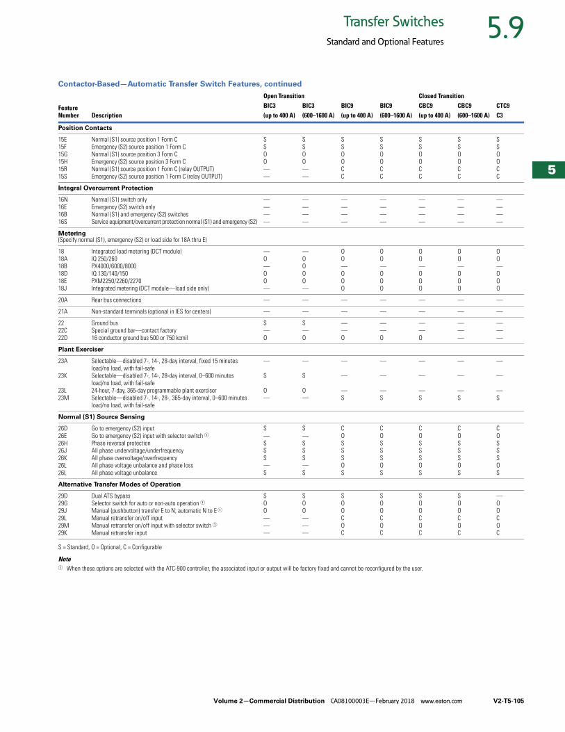
Volume 2—Commercial Distribution CA08100003E—February 2018 www.eaton.com V2-T5-105
5
5
5
5
5
5
5
5
5
5
5
5
5
5
5
5
5
5
5
5
5
5
5
5
5
5
5
5
5
5
5.9Transfer Switches
Standard and Optional Features
Contactor-Based—Automatic Transfer Switch Features, continued
S = Standard, O = Optional, C = Configurable
Note1 When these options are selected with the ATC-900 controller, the associated input or output will be factory fixed and cannot be reconfigured by the user.
FeatureNumber Description
Open Transition Closed TransitionBIC3 BIC3 BIC9 BIC9 CBC9 CBC9 CTC9(up to 400 A) (600–1600 A) (up to 400 A) (600–1600 A) (up to 400 A) (600–1600 A) C3
Position Contacts
15E15F15G15H15R15S
Normal (S1) source position 1 Form CEmergency (S2) source position 1 Form CNormal (S1) source position 3 Form CEmergency (S2) source position 3 Form CNormal (S1) source position 1 Form C (relay OUTPUT)Emergency (S2) source position 1 Form C (relay OUTPUT)
SSOO——
SSOO——
SSOOCC
SSOOCC
SSOOCC
SSOOCC
SSOOCC
Integral Overcurrent Protection
16N16E16B16S
Normal (S1) switch onlyEmergency (S2) switch onlyNormal (S1) and emergency (S2) switchesService equipment/overcurrent protection normal (S1) and emergency (S2)
————
————
————
————
————
————
————
Metering(Specify normal (S1), emergency (S2) or load side for 18A thru E)
1818A18B18D18E18J
Integrated load metering (DCT module)IQ 250/260PX4000/6000/8000IQ 130/140/150PXM2250/2260/2270Integrated metering (DCT module—load side only)
—O—OO—
—OOOO—
OO—OOO
OO—OOO
OO—OOO
OO—OOO
OO—OOO
20A Rear bus connections — — — — — — —
21A Non-standard terminals (optional in IES for centers) — — — — — — —
2222C22D
Ground busSpecial ground bar—contact factory16 conductor ground bus 500 or 750 kcmil
S—O
S—O
——O
——O
——O
———
———
Plant Exerciser
23A
23K
23L23M
Selectable—disabled 7-, 14-, 28-day interval, fixed 15 minutesload/no load, with fail-safeSelectable—disabled 7-, 14-, 28-day interval, 0–600 minutesload/no load, with fail-safe24-hour, 7-day, 365-day programmable plant exerciserSelectable—disabled 7-, 14-, 28-, 365-day interval, 0–600 minutesload/no load, with fail-safe
—
S
O—
—
S
O—
—
—
—S
—
—
—S
—
—
—S
—
—
—S
—
—
—S
Normal (S1) Source Sensing
26D26E26H26J26K26L26L
Go to emergency (S2) inputGo to emergency (S2) input with selector switch 1Phase reversal protectionAll phase undervoltage/underfrequencyAll phase overvoltage/overfrequencyAll phase voltage unbalance and phase lossAll phase voltage unbalance
S—SSS—S
S—SSS—S
COSSSOS
COSSSOS
COSSSOS
COSSSOS
COSSSOS
Alternative Transfer Modes of Operation
29D29G29J29L29M29K
Dual ATS bypassSelector switch for auto or non-auto operation 1Manual (pushbutton) transfer E to N; automatic N to E 1
Manual retransfer on/off inputManual retransfer on/off input with selector switch 1Manual retransfer input
SOO———
SOO———
SOOCOC
SOOCOC
SOOCOC
SOOCOC
—OOCOC
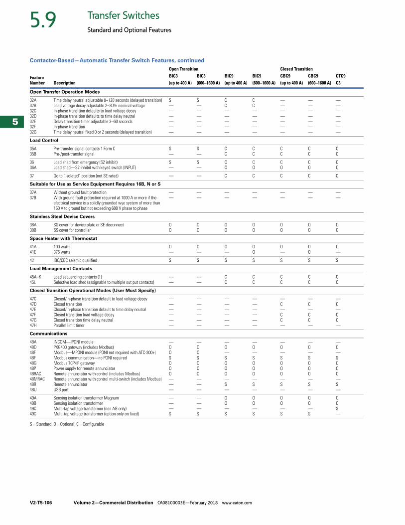
V2-T5-106 Volume 2—Commercial Distribution CA08100003E—February 2018 www.eaton.com
5
5
5
5
5
5
5
5
5
5
5
5
5
5
5
5
5
5
5
5
5
5
5
5
5
5
5
5
5
5
5.9 Transfer Switches
Standard and Optional Features
Contactor-Based—Automatic Transfer Switch Features, continued
S = Standard, O = Optional, C = Configurable
FeatureNumber Description
Open Transition Closed TransitionBIC3 BIC3 BIC9 BIC9 CBC9 CBC9 CTC9(up to 400 A) (600–1600 A) (up to 400 A) (600–1600 A) (up to 400 A) (600–1600 A) C3
Open Transfer Operation Modes
32A32B32C32D32E32F32G
Time delay neutral adjustable 0–120 seconds (delayed transition)Load voltage decay adjustable 2–30% nominal voltageIn-phase transition defaults to load voltage decayIn-phase transition defaults to time delay neutralDelay transition timer adjustable 3–60 secondsIn-phase transitionTime delay neutral fixed 0 or 2 seconds (delayed transition)
S——————
S——————
CC—————
CC—————
———————
———————
———————
Load Control
35A 35B
Pre-transfer signal contacts 1 Form CPre-/post-transfer signal
S—
S—
CC
CC
CC
CC
CC
3636A
Load shed from emergency (S2 inhibit)Load shed—S2 inhibit with keyed switch (INPUT)
S—
S—
CO
CO
CO
CO
CO
37 Go to “isolated” position (not SE rated) — — C C C C C
Suitable for Use as Service Equipment Requires 16B, N or S
37A37B
Without ground fault protectionWith ground fault protection required at 1000 A or more if the electrical service is a solidly grounded wye system of more than 150 V to ground but not exceeding 600 V phase to phase
——
——
——
——
——
——
——
Stainless Steel Device Covers
38A38B
SS cover for device plate or SE disconnectSS cover for controller
OO
OO
OO
OO
OO
OO
OO
Space Heater with Thermostat
41A41E
100 watts375 watts
O—
O—
O—
OO
O—
OO
O—
42 IBC/CBC seismic qualified S S S S S S S
Load Management Contacts
45A–K45L
Load sequencing contacts (1) Selective load shed (assignable to multiple out put contacts)
——
——
CC
CC
CC
CC
CC
Closed Transition Operational Modes (User Must Specify)
47C47D47E47F47G47H
Closed/in-phase transition default to load voltage decayClosed transitionClosed/in-phase transition default to time delay neutral Closed transition load voltage decayClosed transition time delay neutral Parallel limit timer
——————
——————
——————
——————
—C—CC—
—C—CC—
—C—CC—
Communications
48A48D48F48F48G48P48RAC48MRAC48R48U
INCOM—IPONI modulePXG400 gateway (includes Modbus)Modbus—MPONI module (PONI not required with ATC-300+)Modbus communication—no PONI requiredModbus TCP/IP gatewayPower supply for remote annunciatorRemote annunciator with control (includes Modbus)Remote annunciator with control multi-switch (includes Modbus)Remote annunciatorUSB port
—OOSOOO———
—OOSOOO———
—O—SOOO—S—
—O—SOOO—S—
—O—SOOO—S—
—O—SOOO—S—
—O—SOOO—S—
49A49B49C49C
Sensing isolation transformer MagnumSensing isolation transformer Multi-tap voltage transformer (non AG only)Multi-tap voltage transformer (option only on fixed)
———S
———S
OO—S
OO—S
OO—S
OO—S
OOS—
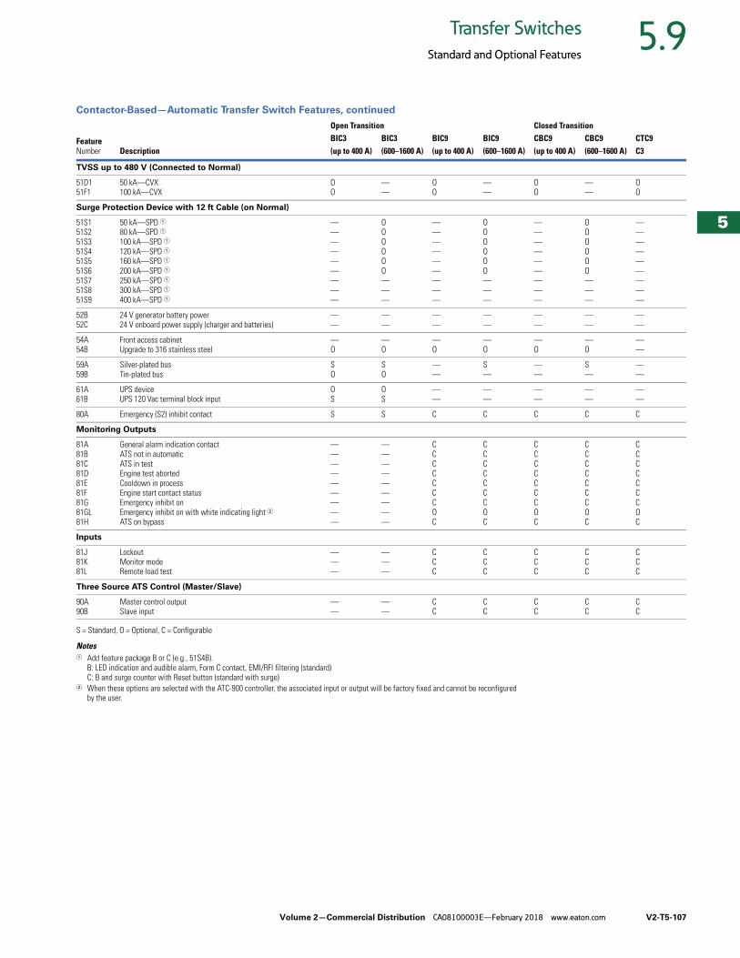
Volume 2—Commercial Distribution CA08100003E—February 2018 www.eaton.com V2-T5-107
5
5
5
5
5
5
5
5
5
5
5
5
5
5
5
5
5
5
5
5
5
5
5
5
5
5
5
5
5
5
5.9Transfer Switches
Standard and Optional Features
Contactor-Based—Automatic Transfer Switch Features, continued
S = Standard, O = Optional, C = Configurable
Notes1 Add feature package B or C (e.g., 51S4B).
B: LED indication and audible alarm, Form C contact, EMI/RFI filtering (standard)C: B and surge counter with Reset button (standard with surge)
2 When these options are selected with the ATC-900 controller, the associated input or output will be factory fixed and cannot be reconfigured by the user.
FeatureNumber Description
Open Transition Closed TransitionBIC3 BIC3 BIC9 BIC9 CBC9 CBC9 CTC9(up to 400 A) (600–1600 A) (up to 400 A) (600–1600 A) (up to 400 A) (600–1600 A) C3
TVSS up to 480 V (Connected to Normal)
51D151F1
50 kA—CVX100 kA—CVX
OO
——
OO
——
OO
——
OO
Surge Protection Device with 12 ft Cable (on Normal)
51S151S251S351S451S551S651S751S851S9
50 kA—SPD 180 kA—SPD 1100 kA—SPD 1120 kA—SPD 1160 kA—SPD 1200 kA—SPD 1250 kA—SPD 1300 kA—SPD 1400 kA—SPD 1
—————————
OOOOOO———
—————————
OOOOOO———
—————————
OOOOOO———
—————————
52B52C
24 V generator battery power24 V onboard power supply (charger and batteries)
——
——
——
——
——
——
——
54A54B
Front access cabinet Upgrade to 316 stainless steel
—O
—O
—O
—O
—O
—O
——
59A59B
Silver-plated busTin-plated bus
SO
SO
——
S—
——
S—
——
61A61B
UPS deviceUPS 120 Vac terminal block input
OS
OS
——
——
——
——
——
80A Emergency (S2) inhibit contact S S C C C C C
Monitoring Outputs
81A81B81C81D81E81F81G81GL81H
General alarm indication contactATS not in automaticATS in testEngine test abortedCooldown in processEngine start contact statusEmergency inhibit onEmergency inhibit on with white indicating light 2ATS on bypass
—————————
—————————
CCCCCCCOC
CCCCCCCOC
CCCCCCCOC
CCCCCCCOC
CCCCCCCOC
Inputs
81J81K81L
LockoutMonitor modeRemote load test
———
———
CCC
CCC
CCC
CCC
CCC
Three Source ATS Control (Master/Slave)
90A90B
Master control outputSlave input
——
——
CC
CC
CC
CC
CC
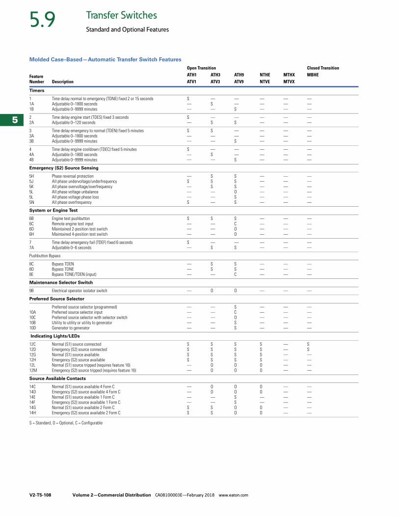
V2-T5-108 Volume 2—Commercial Distribution CA08100003E—February 2018 www.eaton.com
5
5
5
5
5
5
5
5
5
5
5
5
5
5
5
5
5
5
5
5
5
5
5
5
5
5
5
5
5
5
5.9 Transfer Switches
Standard and Optional Features
Molded Case–Based—Automatic Transfer Switch Features
S = Standard, O = Optional, C = Configurable
FeatureNumber Description
Open Transition Closed TransitionATH1 ATH3 ATH9 NTHE MTHX MBHEATV1 ATV3 ATV9 NTVE MTVX
Timers
11A1B
Time delay normal to emergency (TDNE) fixed 2 or 15 secondsAdjustable 0–1800 secondsAdjustable 0–9999 minutes
S——
—S—
——S
———
———
———
22A
Time delay engine start (TDES) fixed 3 secondsAdjustable 0–120 seconds
S—
—S
—S
——
——
——
33A3B
Time delay emergency to normal (TDEN) fixed 5 minutesAdjustable 0–1800 secondsAdjustable 0–9999 minutes
S——
S——
——S
———
———
———
44A4B
Time delay engine cooldown (TDEC) fixed 5 minutesAdjustable 0–1800 secondsAdjustable 0–9999 minutes
S——
—S—
——S
———
———
———
Emergency (S2) Source Sensing
5H5J5K5L5L5N
Phase reversal protectionAll phase undervoltage/underfrequencyAll phase overvoltage/overfrequencyAll phase voltage unbalanceAll phase voltage phase lossAll phase overfrequency
—S———S
SSS———
SSSOSS
——————
——————
——————
System or Engine Test
6B6C6D6H
Engine test pushbuttonRemote engine test inputMaintained 2-position test switchMaintained 4-position test switch
S———
S———
SCOO
————
————
————
77A
Time delay emergency fail (TDEF) fixed 6 secondsAdjustable 0–6 seconds
S—
—S
—S
——
——
——
Pushbutton Bypass
8C8D8E
Bypass TDENBypass TDNEBypass TDNE/TDEN (input)
———
SS—
SSC
———
———
———
Maintenance Selector Switch
9B Electrical operator isolator switch — O O — — —
Preferred Source Selector
10A10C10B10D
Preferred source selector (programmed)Preferred source selector inputPreferred source selector with selector switchUtility to utility or utility to generatorGenerator to generator
—————
—————
SCOSS
—————
—————
—————
Indicating Lights/LEDs
12C12D12G12H12L12M
Normal (S1) source connectedEmergency (S2) source connectedNormal (S1) source availableEmergency (S2) source availableNormal (S1) source tripped (requires feature 16)Emergency (S2) source tripped (requires feature 16)
SSSS——
SSSSOO
SSSSOO
SSSSOO
——————
SS————
Source Available Contacts
14C14D14E14F14G14H
Normal (S1) source available 4 Form CEmergency (S2) source available 4 Form CNormal (S1) source available 1 Form CEmergency (S2) source available 1 Form CNormal (S1) source available 2 Form CEmergency (S2) source available 2 Form C
————SS
OO——SS
OOSSOO
OO——OO
——————
——————
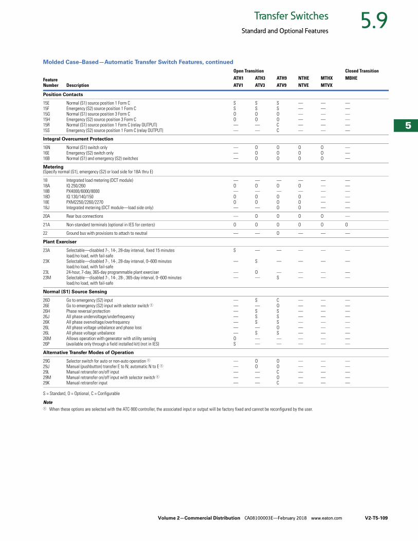
Volume 2—Commercial Distribution CA08100003E—February 2018 www.eaton.com V2-T5-109
5
5
5
5
5
5
5
5
5
5
5
5
5
5
5
5
5
5
5
5
5
5
5
5
5
5
5
5
5
5
5.9Transfer Switches
Standard and Optional Features
Molded Case–Based—Automatic Transfer Switch Features, continued
S = Standard, O = Optional, C = Configurable
Note1 When these options are selected with the ATC-900 controller, the associated input or output will be factory fixed and cannot be reconfigured by the user.
FeatureNumber Description
Open Transition Closed TransitionATH1 ATH3 ATH9 NTHE MTHX MBHEATV1 ATV3 ATV9 NTVE MTVX
Position Contacts
15E15F15G15H15R15S
Normal (S1) source position 1 Form CEmergency (S2) source position 1 Form CNormal (S1) source position 3 Form CEmergency (S2) source position 3 Form CNormal (S1) source position 1 Form C (relay OUTPUT)Emergency (S2) source position 1 Form C (relay OUTPUT)
SSOO——
SSOO——
SSOOCC
——————
——————
——————
Integral Overcurrent Protection
16N16E16B
Normal (S1) switch onlyEmergency (S2) switch onlyNormal (S1) and emergency (S2) switches
———
OOO
OOO
OOO
OOO
———
Metering(Specify normal (S1), emergency (S2) or load side for 18A thru E)
1818A18B18D18E18J
Integrated load metering (DCT module)IQ 250/260PX4000/6000/8000IQ 130/140/150PXM2250/2260/2270Integrated metering (DCT module—load side only)
—O—OO—
—O—OO—
—O—OOO
—O—OOO
——————
——————
20A Rear bus connections — O O O O —
21A Non-standard terminals (optional in IES for centers) O O O O O O
22 Ground bus with provisions to attach to neutral — — O — — —
Plant Exerciser
23A
23K
23L23M
Selectable—disabled 7-, 14-, 28-day interval, fixed 15 minutesload/no load, with fail-safeSelectable—disabled 7-, 14-, 28-day interval, 0–600 minutesload/no load, with fail-safe24-hour, 7-day, 365-day programmable plant exerciserSelectable—disabled 7-, 14-, 28-, 365-day interval, 0–600 minutesload/no load, with fail-safe
S
—
——
—
S
O—
—
—
—S
—
—
——
—
—
——
—
—
——
Normal (S1) Source Sensing
26D26E26H26J26K26L26L26M26P
Go to emergency (S2) inputGo to emergency (S2) input with selector switch 1Phase reversal protectionAll phase undervoltage/underfrequencyAll phase overvoltage/overfrequencyAll phase voltage unbalance and phase lossAll phase voltage unbalanceAllows operation with generator with utility sensing(available only through a field installed kit) (not in IES)
———————OS
S—SSS—S——
COSSSOS——
—————————
—————————
—————————
Alternative Transfer Modes of Operation
29G29J29L29M29K
Selector switch for auto or non-auto operation 1Manual (pushbutton) transfer E to N; automatic N to E 1
Manual retransfer on/off inputManual retransfer on/off input with selector switch 1Manual retransfer input
—————
OO———
OOCOC
—————
—————
—————
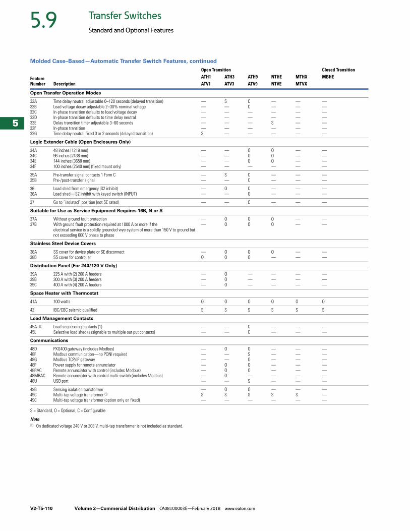
V2-T5-110 Volume 2—Commercial Distribution CA08100003E—February 2018 www.eaton.com
5
5
5
5
5
5
5
5
5
5
5
5
5
5
5
5
5
5
5
5
5
5
5
5
5
5
5
5
5
5
5.9 Transfer Switches
Standard and Optional Features
Molded Case–Based—Automatic Transfer Switch Features, continued
S = Standard, O = Optional, C = Configurable
Note1 On dedicated voltage 240 V or 208 V, multi-tap transformer is not included as standard.
FeatureNumber Description
Open Transition Closed TransitionATH1 ATH3 ATH9 NTHE MTHX MBHEATV1 ATV3 ATV9 NTVE MTVX
Open Transfer Operation Modes
32A32B32C32D32E32F32G
Time delay neutral adjustable 0–120 seconds (delayed transition)Load voltage decay adjustable 2–30% nominal voltageIn-phase transition defaults to load voltage decayIn-phase transition defaults to time delay neutralDelay transition timer adjustable 3–60 secondsIn-phase transitionTime delay neutral fixed 0 or 2 seconds (delayed transition)
——————S
S——————
CC—————
————S——
———————
———————
Logic Extender Cable (Open Enclosures Only)
34A34C34E34F
48 inches (1219 mm)96 inches (2438 mm)144 inches (3658 mm)100 inches (2540 mm) (fixed mount only)
————
————
OOO—
OOO—
————
————
35A 35B
Pre-transfer signal contacts 1 Form CPre-/post-transfer signal
——
S—
CC
——
——
——
3636A
Load shed from emergency (S2 inhibit)Load shed—S2 inhibit with keyed switch (INPUT)
——
O—
CO
——
——
——
37 Go to “isolated” position (not SE rated) — — C — — —
Suitable for Use as Service Equipment Requires 16B, N or S
37A37B
Without ground fault protectionWith ground fault protection required at 1000 A or more if the electrical service is a solidly grounded wye system of more than 150 V to ground but not exceeding 600 V phase to phase
——
OO
OO
OO
——
——
Stainless Steel Device Covers
38A38B
SS cover for device plate or SE disconnectSS cover for controller
—O
OO
OO
O—
——
——
Distribution Panel (For 240/120 V Only)
39A39B39C
225 A with (2) 200 A feeders300 A with (3) 200 A feeders400 A with (4) 200 A feeders
———
OOO
———
———
———
———
Space Heater with Thermostat
41A 100 watts O O O O O O
42 IBC/CBC seismic qualified S S S S S S
Load Management Contacts
45A–K45L
Load sequencing contacts (1) Selective load shed (assignable to multiple out put contacts)
——
——
CC
——
——
——
Communications
48D48F48G48P48RAC48MRAC48U
PXG400 gateway (includes Modbus)Modbus communication—no PONI requiredModbus TCP/IP gatewayPower supply for remote annunciatorRemote annunciator with control (includes Modbus)Remote annunciator with control multi-switch (includes Modbus)USB port
———————
O——OOO—
OSOOO—S
———————
———————
———————
49B49C49C
Sensing isolation transformer Multi-tap voltage transformer 1Multi-tap voltage transformer (option only on fixed)
—S—
OS—
OS—
—S—
—S—
———
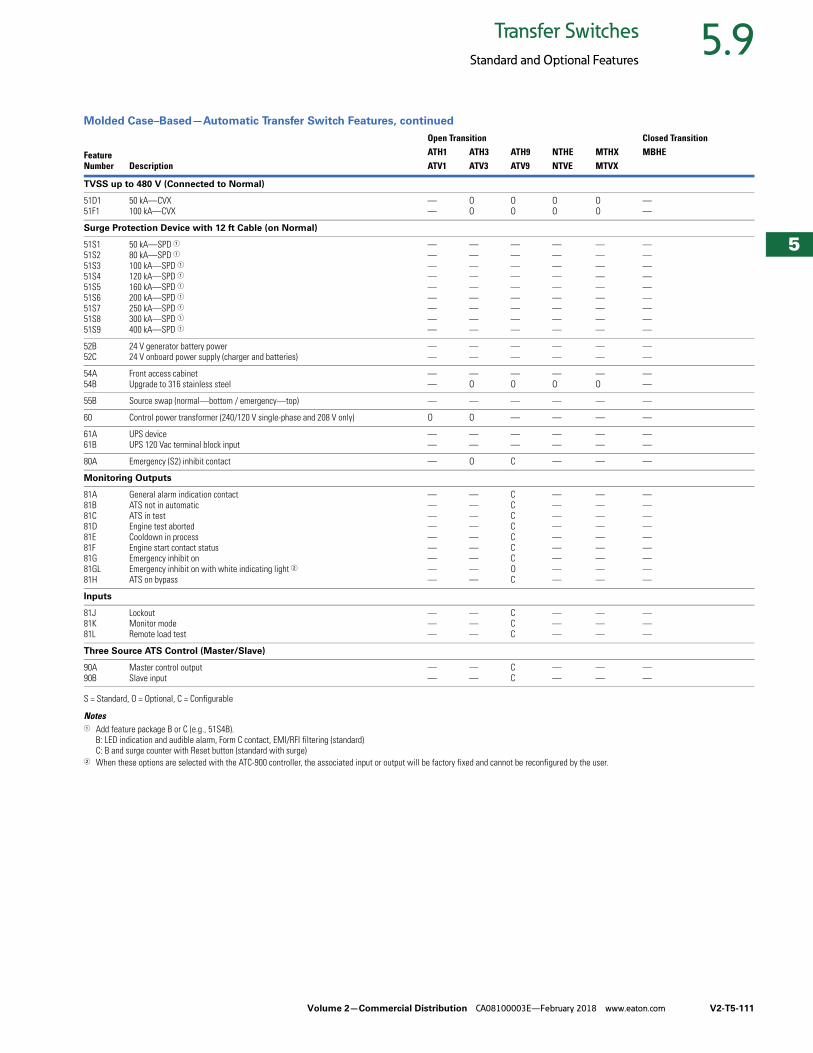
Volume 2—Commercial Distribution CA08100003E—February 2018 www.eaton.com V2-T5-111
5
5
5
5
5
5
5
5
5
5
5
5
5
5
5
5
5
5
5
5
5
5
5
5
5
5
5
5
5
5
5.9Transfer Switches
Standard and Optional Features
Molded Case–Based—Automatic Transfer Switch Features, continued
S = Standard, O = Optional, C = Configurable
Notes1 Add feature package B or C (e.g., 51S4B).
B: LED indication and audible alarm, Form C contact, EMI/RFI filtering (standard)C: B and surge counter with Reset button (standard with surge)
2 When these options are selected with the ATC-900 controller, the associated input or output will be factory fixed and cannot be reconfigured by the user.
FeatureNumber Description
Open Transition Closed TransitionATH1 ATH3 ATH9 NTHE MTHX MBHEATV1 ATV3 ATV9 NTVE MTVX
TVSS up to 480 V (Connected to Normal)
51D151F1
50 kA—CVX100 kA—CVX
——
OO
OO
OO
OO
——
Surge Protection Device with 12 ft Cable (on Normal)
51S151S251S351S451S551S651S751S851S9
50 kA—SPD 180 kA—SPD 1100 kA—SPD 1120 kA—SPD 1160 kA—SPD 1200 kA—SPD 1250 kA—SPD 1300 kA—SPD 1400 kA—SPD 1
—————————
—————————
—————————
—————————
—————————
—————————
52B52C
24 V generator battery power24 V onboard power supply (charger and batteries)
——
——
——
——
——
——
54A54B
Front access cabinet Upgrade to 316 stainless steel
——
—O
—O
—O
—O
——
55B Source swap (normal—bottom / emergency—top) — — — — — —
60 Control power transformer (240/120 V single-phase and 208 V only) O O — — — —
61A61B
UPS deviceUPS 120 Vac terminal block input
——
——
——
——
——
——
80A Emergency (S2) inhibit contact — O C — — —
Monitoring Outputs
81A81B81C81D81E81F81G81GL81H
General alarm indication contactATS not in automaticATS in testEngine test abortedCooldown in processEngine start contact statusEmergency inhibit onEmergency inhibit on with white indicating light 2
ATS on bypass
—————————
—————————
CCCCCCCOC
—————————
—————————
—————————
Inputs
81J81K81L
LockoutMonitor modeRemote load test
———
———
CCC
———
———
———
Three Source ATS Control (Master/Slave)
90A90B
Master control outputSlave input
——
——
CC
——
——
——
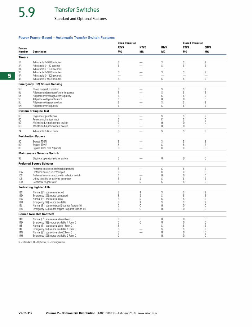
V2-T5-112 Volume 2—Commercial Distribution CA08100003E—February 2018 www.eaton.com
5
5
5
5
5
5
5
5
5
5
5
5
5
5
5
5
5
5
5
5
5
5
5
5
5
5
5
5
5
5
5.9 Transfer Switches
Standard and Optional Features
Power Frame–Based—Automatic Transfer Switch Features
S = Standard, O = Optional, C = Configurable
FeatureNumber Description
Open Transition Closed TransitionATV9 NTVE BIV9 CTV9 CBV9MG MG MG MG MG
Timers
1B2A3A3B4A4B
Adjustable 0–9999 minutesAdjustable 0–120 secondsAdjustable 0–1800 secondsAdjustable 0–9999 minutesAdjustable 0–1800 secondsAdjustable 0–9999 minutes
SS—S—S
——————
SS—S—S
SS—S—S
SS—S—S
Emergency (S2) Source Sensing
5H5J5K5L5L5N
Phase reversal protectionAll phase undervoltage/underfrequencyAll phase overvoltage/overfrequencyAll phase voltage unbalanceAll phase voltage phase lossAll phase overfrequency
SSSOSS
——————
SSSOSS
SSSOSS
SSSOSS
System or Engine Test
6B6C6D6H
Engine test pushbuttonRemote engine test inputMaintained 2-position test switchMaintained 4-position test switch
SCOO
————
SCOO
SCOO
SCOO
7A Adjustable 0–6 seconds S — S S S
Pushbutton Bypass
8C8D8E
Bypass TDENBypass TDNEBypass TDNE/TDEN (input)
SSC
———
SSC
SSC
SSC
Maintenance Selector Switch
9B Electrical operator isolator switch O — O O O
Preferred Source Selector
10A10C10B10D
Preferred source selector (programmed)Preferred source selector inputPreferred source selector with selector switchUtility to utility or utility to generatorGenerator to generator
SCOSS
———SS
SCOSS
SCOSS
SCOSS
Indicating Lights/LEDs
12C12D12G12H12L12M
Normal (S1) source connectedEmergency (S2) source connectedNormal (S1) source availableEmergency (S2) source availableNormal (S1) source tripped (requires feature 16)Emergency (S2) source tripped (requires feature 16)
SSSSOO
SSSSOO
SSSSOO
SSSSOO
SSSSOO
Source Available Contacts
14C14D14E14F14G14H
Normal (S1) source available 4 Form CEmergency (S2) source available 4 Form CNormal (S1) source available 1 Form CEmergency (S2) source available 1 Form CNormal (S1) source available 2 Form CEmergency (S2) source available 2 Form C
OOSSOO
OO————
OOSSOO
OOSSOO
OOSSOO
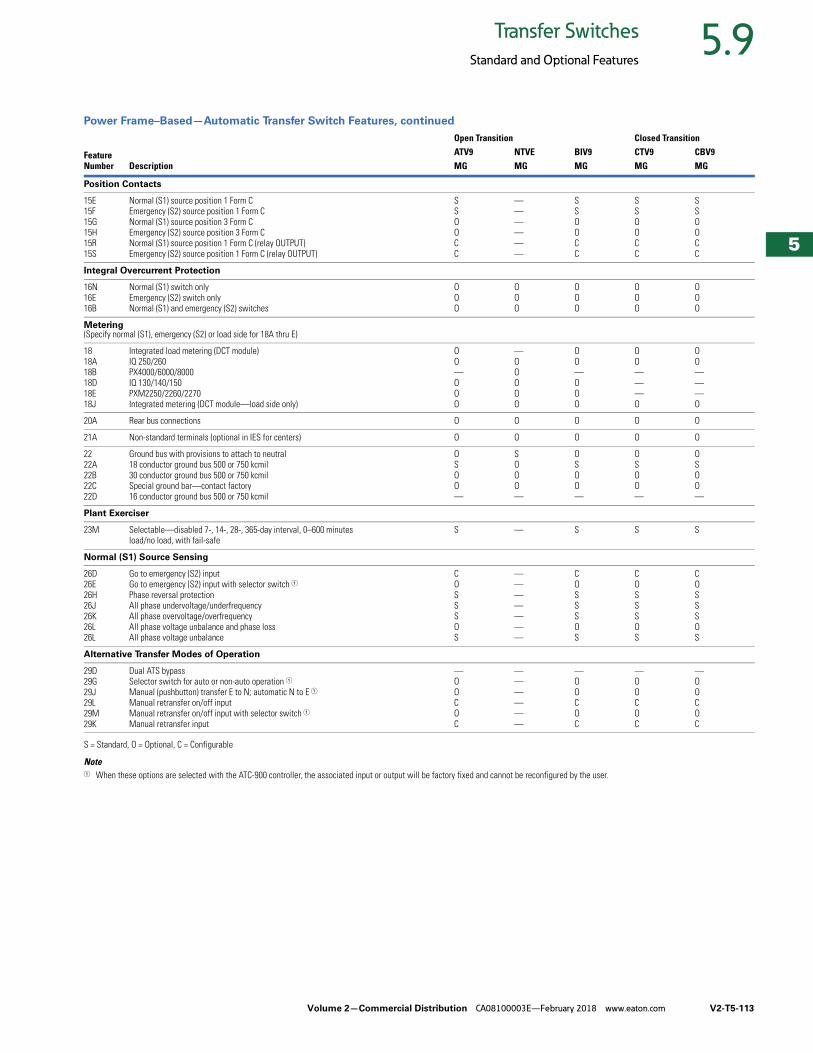
Volume 2—Commercial Distribution CA08100003E—February 2018 www.eaton.com V2-T5-113
5
5
5
5
5
5
5
5
5
5
5
5
5
5
5
5
5
5
5
5
5
5
5
5
5
5
5
5
5
5
5.9Transfer Switches
Standard and Optional Features
Power Frame–Based—Automatic Transfer Switch Features, continued
S = Standard, O = Optional, C = Configurable
Note1 When these options are selected with the ATC-900 controller, the associated input or output will be factory fixed and cannot be reconfigured by the user.
FeatureNumber Description
Open Transition Closed TransitionATV9 NTVE BIV9 CTV9 CBV9MG MG MG MG MG
Position Contacts
15E15F15G15H15R15S
Normal (S1) source position 1 Form CEmergency (S2) source position 1 Form CNormal (S1) source position 3 Form CEmergency (S2) source position 3 Form CNormal (S1) source position 1 Form C (relay OUTPUT)Emergency (S2) source position 1 Form C (relay OUTPUT)
SSOOCC
——————
SSOOCC
SSOOCC
SSOOCC
Integral Overcurrent Protection
16N16E16B
Normal (S1) switch onlyEmergency (S2) switch onlyNormal (S1) and emergency (S2) switches
OOO
OOO
OOO
OOO
OOO
Metering(Specify normal (S1), emergency (S2) or load side for 18A thru E)
1818A18B18D18E18J
Integrated load metering (DCT module)IQ 250/260PX4000/6000/8000IQ 130/140/150PXM2250/2260/2270Integrated metering (DCT module—load side only)
OO—OOO
—OOOOO
OO—OOO
OO———O
OO———O
20A Rear bus connections O O O O O
21A Non-standard terminals (optional in IES for centers) O O O O O
2222A22B22C22D
Ground bus with provisions to attach to neutral18 conductor ground bus 500 or 750 kcmil30 conductor ground bus 500 or 750 kcmilSpecial ground bar—contact factory16 conductor ground bus 500 or 750 kcmil
OSOO—
SOOO—
OSOO—
OSOO—
OSOO—
Plant Exerciser
23M Selectable—disabled 7-, 14-, 28-, 365-day interval, 0–600 minutesload/no load, with fail-safe
S — S S S
Normal (S1) Source Sensing
26D26E26H26J26K26L26L
Go to emergency (S2) inputGo to emergency (S2) input with selector switch 1Phase reversal protectionAll phase undervoltage/underfrequencyAll phase overvoltage/overfrequencyAll phase voltage unbalance and phase lossAll phase voltage unbalance
COSSSOS
———————
COSSSOS
COSSSOS
COSSSOS
Alternative Transfer Modes of Operation
29D29G29J29L29M29K
Dual ATS bypassSelector switch for auto or non-auto operation 1Manual (pushbutton) transfer E to N; automatic N to E 1
Manual retransfer on/off inputManual retransfer on/off input with selector switch 1Manual retransfer input
—OOCOC
——————
—OOCOC
—OOCOC
—OOCOC
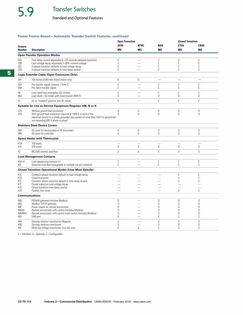
V2-T5-114 Volume 2—Commercial Distribution CA08100003E—February 2018 www.eaton.com
5
5
5
5
5
5
5
5
5
5
5
5
5
5
5
5
5
5
5
5
5
5
5
5
5
5
5
5
5
5
5.9 Transfer Switches
Standard and Optional Features
Power Frame–Based—Automatic Transfer Switch Features, continued
S = Standard, O = Optional, C = Configurable
FeatureNumber Description
Open Transition Closed TransitionATV9 NTVE BIV9 CTV9 CBV9MG MG MG MG MG
Open Transfer Operation Modes
32A32B32C32D
Time delay neutral adjustable 0–120 seconds (delayed transition)Load voltage decay adjustable 2–30% nominal voltageIn-phase transition defaults to load voltage decayIn-phase transition defaults to time delay neutral
CCCC
————
CCCC
CCCC
CCCC
Logic Extender Cable (Open Enclosures Only)
34F 100 inches (2540 mm) (fixed mount only) O O — — —
35A 35B
Pre-transfer signal contacts 1 Form CPre-/post-transfer signal
CC
——
CC
CC
CC
3636A
Load shed from emergency (S2 inhibit)Load shed—S2 inhibit with keyed switch (INPUT)
CO
——
CO
CO
CO
37 Go to “isolated” position (not SE rated) C — C C C
Suitable for Use as Service Equipment Requires 16B, N or S
37A37B
Without ground fault protectionWith ground fault protection required at 1000 A or more if the electrical service is a solidly grounded wye system of more than 150 V to ground but not exceeding 600 V phase to phase
OO
OO
OO
OO
OO
Stainless Steel Device Covers
38A38B
SS cover for device plate or SE disconnectSS cover for controller
OO
OO
OO
OO
OO
Space Heater with Thermostat
41A41E
100 watts375 watts
—O
—O
—O
—O
—O
42 IBC/CBC seismic qualified S S S S S
Load Management Contacts
45A–K45L
Load sequencing contacts (1) Selective load shed (assignable to multiple out put contacts)
CC
——
CC
CC
CC
Closed Transition Operational Modes (User Must Specify)
47C47D47E47F47G47H
Closed/in-phase transition default to load voltage decayClosed transitionClosed/in-phase transition default to time delay neutral Closed transition load voltage decayClosed transition time delay neutral Parallel limit timer
——————
——————
——————
CCC——S
CCC——S
Communications
48D48G48P48RAC48MRAC48U
PXG400 gateway (includes Modbus)Modbus TCP/IP gatewayPower supply for remote annunciatorRemote annunciator with control (includes Modbus)Remote annunciator with control multi-switch (includes Modbus)USB port
OOOOOS
——————
OOOOOS
OOOOOS
OOOOOS
49A49B49C
Sensing isolation transformer MagnumSensing isolation transformer Multi-tap voltage transformer (non AG only)
OOS
——S
OOS
OOS
OOS
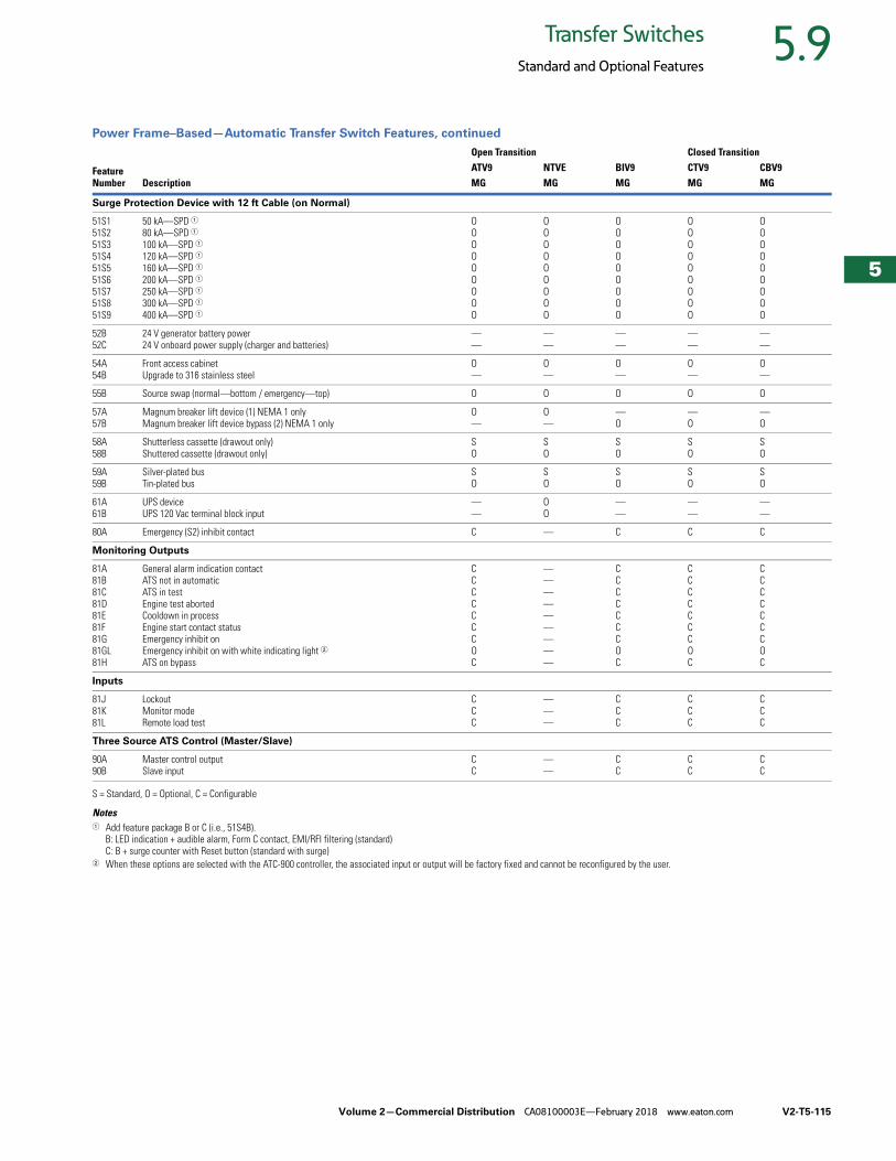
Volume 2—Commercial Distribution CA08100003E—February 2018 www.eaton.com V2-T5-115
5
5
5
5
5
5
5
5
5
5
5
5
5
5
5
5
5
5
5
5
5
5
5
5
5
5
5
5
5
5
5.9Transfer Switches
Standard and Optional Features
Power Frame–Based—Automatic Transfer Switch Features, continued
S = Standard, O = Optional, C = Configurable
Notes1 Add feature package B or C (i.e., 51S4B).
B: LED indication + audible alarm, Form C contact, EMI/RFI filtering (standard)C: B + surge counter with Reset button (standard with surge)
2 When these options are selected with the ATC-900 controller, the associated input or output will be factory fixed and cannot be reconfigured by the user.
FeatureNumber Description
Open Transition Closed TransitionATV9 NTVE BIV9 CTV9 CBV9MG MG MG MG MG
Surge Protection Device with 12 ft Cable (on Normal)
51S151S251S351S451S551S651S751S851S9
50 kA—SPD 180 kA—SPD 1100 kA—SPD 1120 kA—SPD 1160 kA—SPD 1200 kA—SPD 1250 kA—SPD 1300 kA—SPD 1400 kA—SPD 1
OOOOOOOOO
OOOOOOOOO
OOOOOOOOO
OOOOOOOOO
OOOOOOOOO
52B52C
24 V generator battery power24 V onboard power supply (charger and batteries)
——
——
——
——
——
54A54B
Front access cabinet Upgrade to 316 stainless steel
O—
O—
O—
O—
O—
55B Source swap (normal—bottom / emergency—top) O O O O O
57A57B
Magnum breaker lift device (1) NEMA 1 onlyMagnum breaker lift device bypass (2) NEMA 1 only
O—
O—
—O
—O
—O
58A58B
Shutterless cassette (drawout only)Shuttered cassette (drawout only)
SO
SO
SO
SO
SO
59A59B
Silver-plated busTin-plated bus
SO
SO
SO
SO
SO
61A61B
UPS deviceUPS 120 Vac terminal block input
——
OO
——
——
——
80A Emergency (S2) inhibit contact C — C C C
Monitoring Outputs
81A81B81C81D81E81F81G81GL81H
General alarm indication contactATS not in automaticATS in testEngine test abortedCooldown in processEngine start contact statusEmergency inhibit onEmergency inhibit on with white indicating light 2
ATS on bypass
CCCCCCCOC
—————————
CCCCCCCOC
CCCCCCCOC
CCCCCCCOC
Inputs
81J81K81L
LockoutMonitor modeRemote load test
CCC
———
CCC
CCC
CCC
Three Source ATS Control (Master/Slave)
90A90B
Master control outputSlave input
CC
——
CC
CC
CC
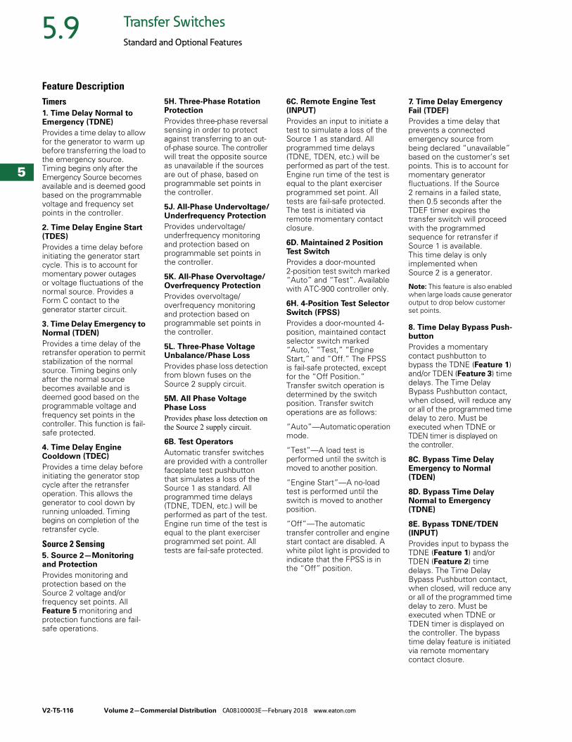
V2-T5-116 Volume 2—Commercial Distribution CA08100003E—February 2018 www.eaton.com
5
5
5
5
5
5
5
5
5
5
5
5
5
5
5
5
5
5
5
5
5
5
5
5
5
5
5
5
5
5
5.9 Transfer Switches
Standard and Optional Features
Feature DescriptionTimers1. Time Delay Normal to Emergency (TDNE)
Provides a time delay to allow for the generator to warm up before transferring the load to the emergency source. Timing begins only after the Emergency Source becomes available and is deemed good based on the programmable voltage and frequency set points in the controller.
2. Time Delay Engine Start (TDES)
Provides a time delay before initiating the generator start cycle. This is to account for momentary power outages or voltage fluctuations of the normal source. Provides a Form C contact to the generator starter circuit.
3. Time Delay Emergency to Normal (TDEN)
Provides a time delay of the retransfer operation to permit stabilization of the normal source. Timing begins only after the normal source becomes available and is deemed good based on the programmable voltage and frequency set points in the controller. This function is fail-safe protected.
4. Time Delay Engine Cooldown (TDEC)
Provides a time delay before initiating the generator stop cycle after the retransfer operation. This allows the generator to cool down by running unloaded. Timing begins on completion of the retransfer cycle.
Source 2 Sensing5. Source 2—Monitoring and Protection
Provides monitoring and protection based on the Source 2 voltage and/or frequency set points. All Feature 5 monitoring and protection functions are fail-safe operations.
5H. Three-Phase Rotation Protection
Provides three-phase reversal sensing in order to protect against transferring to an out-of-phase source. The controller will treat the opposite source as unavailable if the sources are out of phase, based on programmable set points in the controller.
5J. All-Phase Undervoltage/Underfrequency Protection
Provides undervoltage/underfrequency monitoring and protection based on programmable set points in the controller.
5K. All-Phase Overvoltage/Overfrequency Protection
Provides overvoltage/overfrequency monitoring and protection based on programmable set points in the controller.
5L. Three-Phase Voltage Unbalance/Phase Loss
Provides phase loss detection from blown fuses on the Source 2 supply circuit.
5M. All Phase Voltage Phase Loss
Provides phase loss detection on the Source 2 supply circuit.
6B. Test Operators
Automatic transfer switches are provided with a controller faceplate test pushbutton that simulates a loss of the Source 1 as standard. All programmed time delays (TDNE, TDEN, etc.) will be performed as part of the test. Engine run time of the test is equal to the plant exerciser programmed set point. All tests are fail-safe protected.
6C. Remote Engine Test (INPUT)
Provides an input to initiate a test to simulate a loss of the Source 1 as standard. All programmed time delays (TDNE, TDEN, etc.) will be performed as part of the test. Engine run time of the test is equal to the plant exerciser programmed set point. All tests are fail-safe protected. The test is initiated via remote momentary contact closure.
6D. Maintained 2 Position Test Switch
Provides a door-mounted 2-position test switch marked “Auto” and “Test”. Available with ATC-900 controller only.
6H. 4-Position Test Selector Switch (FPSS)
Provides a door-mounted 4-position, maintained contact selector switch marked “Auto,” “Test,” “Engine Start,” and “Off.” The FPSS is fail-safe protected, except for the “Off Position.” Transfer switch operation is determined by the switch position. Transfer switch operations are as follows:
“Auto”—Automatic operation mode.
“Test”—A load test is performed until the switch is moved to another position.
“Engine Start”—A no-load test is performed until the switch is moved to another position.
“Off”—The automatic transfer controller and engine start contact are disabled. A white pilot light is provided to indicate that the FPSS is in the “Off” position.
7. Time Delay Emergency Fail (TDEF)
Provides a time delay that prevents a connected emergency source from being declared “unavailable” based on the customer’s set points. This is to account for momentary generator fluctuations. If the Source 2 remains in a failed state, then 0.5 seconds after the TDEF timer expires the transfer switch will proceed with the programmed sequence for retransfer if Source 1 is available. This time delay is only implemented when Source 2 is a generator.
Note: This feature is also enabled when large loads cause generator output to drop below customer set points.
8. Time Delay Bypass Push-button
Provides a momentary contact pushbutton to bypass the TDNE (Feature 1) and/or TDEN (Feature 3) time delays. The Time Delay Bypass Pushbutton contact, when closed, will reduce any or all of the programmed time delay to zero. Must be executed when TDNE or TDEN timer is displayed on the controller.
8C. Bypass Time Delay Emergency to Normal (TDEN)
8D. Bypass Time Delay Normal to Emergency (TDNE)
8E. Bypass TDNE/TDEN (INPUT)
Provides input to bypass the TDNE (Feature 1) and/or TDEN (Feature 2) time delays. The Time Delay Bypass Pushbutton contact, when closed, will reduce any or all of the programmed time delay to zero. Must be executed when TDNE or TDEN timer is displayed on the controller. The bypass time delay feature is initiated via remote momentary contact closure.
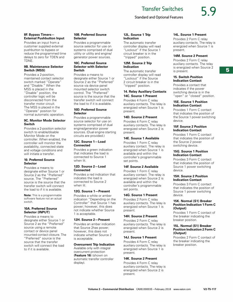
Volume 2—Commercial Distribution CA08100003E—February 2018 www.eaton.com V2-T5-117
5
5
5
5
5
5
5
5
5
5
5
5
5
5
5
5
5
5
5
5
5
5
5
5
5
5
5
5
5
5
5.9Transfer Switches
Standard and Optional Features
8F. Bypass Timers—External Pushbutton Input
Provides an input from a customer supplied external pushbutton to bypass or reduce the programmed time delays to zero for TDEN and TDNE.
9B. Maintenance Selector Switch (MSS)
Provides a 2-position, maintained contact selector switch marked “Operate” and “Disable.” When the MSS is placed in the “Disable” position, the controller logic will be disconnected from the transfer motor circuit. The MSS is placed in the “Operate” position for normal automatic operation.
9C. Monitor Mode Selector Switch
Provides a 2-position selector switch to enable/disable Monitor Mode on the controller. When enabled, the controller will monitor the availability, connected state and voltage conditions and will initiate a transfer.
10. Preferred Source Selector
Provides a means to designate either Source 1 or Source 2 as the “Preferred” source. The “Preferred” source is the source that the transfer switch will connect the load to if it is available.
Note: This is a programmable software feature not an actual switch.
10A. Preferred Source Selector (INPUT)
Provides a means to designate either Source 1 or Source 2 as the “Preferred” source using a remote contact or device panel mounted contact closure. The “Preferred” source is the source that the transfer switch will connect the load to if it is available.
10B. Preferred Source Selector
Provides a programmable source selector for use on systems comprised of dual utility or utility and engine/ generator power sources.
10C. Preferred Source Selector with Selector Switch
Provides a means to designate either Source 1 or Source 2 as the “Preferred” source via device panel mounted selector switch control. The “Preferred” source is the source that the transfer switch will connect the load to if it is available.
10D. Preferred Source Selector
Provides a programmable source selector for use on systems comprised of dual engine/generator power sources. (Dual engine starting circuits are provided.)
12C. Source 1—Load Connected
Provides a green indication that indicates the load is connected to Source 1 when lit.
12D. Source 2—Load Connected
Provides a red indication that indicates the load is connected to Source 2when lit.
12G. Source 1—Present
Provides a white or amber indication “Depending on the Controller” that Source 1 has power; however, this does not indicate whether Source 1 is acceptable.
12H. Source 2—Present
Provides an amber indication that Source 2has power; however, this does not indicate whether Source 2is acceptable.
Overcurrent Trip IndicationAvailable only with integral overcurrent protection (Feature 16) (shown on automatic transfer controller display).
12L. Source 1 Trip Indication
The automatic transfer controller display will read “Lockout” if the Source 1 circuit breaker is in the “tripped” position.
12M. Source 2 Trip Indication
The automatic transfer controller display will read “Lockout” if the Source 2 circuit breaker is in the “tripped” position.
14. Relay Auxiliary Contacts
14C. Source 1 Present
Provides 4 Form C relay auxiliary contacts. The relay is energized when Source 1 is present.
14D. Source 2 Present
Provides 4 Form C relay auxiliary contacts. The relay is energized when Source 2 is present.
14E. Source 1 Available
Provides 1 Form C relay auxiliary contact. The relay is energized when Source 1 is available and within the controller’s programmable set points.
14F. Source 2 Available
Provides 1 Form C relay auxiliary contact. The relay is energized when Source 2 is available and within the controller’s programmable set points.
14G. Source 1 Present
Provides 2 Form C relay auxiliary contacts. The relay is energized when Source 1 is present.
14H. Source 2 Present
Provides 2 Form C relay auxiliary contacts. The relay is energized when Source 2 is present.
14J. Source 1 Present
Provides 4 Form C relay auxiliary contacts. The relay is energized when Source 1 is present.
14K. Source 2 Present
Provides 4 Form C relay auxiliary contacts. The relay is energized when Source 2 is present.
14L. Source 1 Present
Provides 2 Form C relay auxiliary contacts. The relay is energized when Source 1 is present.
14M. Source 2 Present
Provides 2 Form C relay auxiliary contacts. The relay is energized when Source 2 is present.
15. Switch Position Indication Contact
Provides a contact that indicates if the power switching device is in the “open” or “closed” position.
15E. Source 1 Position Indication Contact
Provides 1 Form C contact that indicates the position of the Source 1 power switching device.
15F. Source 2 Position Indication Contact
Provides 1 Form C contact that indicates the position of the Source 2 power switching device.
15G. Source 1 Position Indication Contact
Provides 3 Form C contact that indicates the position of Source 1 power switching device.
15H. Source 2 Position Indication Contact
Provides 3 Form C contact that indicates the position of Source 1 power switching device.
15K. Normal (S1) Breaker Position Indication 1 Form C (Output)
Provides 1 Form C contact of the breaker indicating the breaker position.
15L. Normal (S1) Breaker Position Indication 2 Form C (Output)
Provides 2 Form C contact of the breaker indicating the breaker position.
V2-T5-118 Volume 2—Commercial Distribution CA08100003E—February 2018 www.eaton.com
5
5
5
5
5
5
5
5
5
5
5
5
5
5
5
5
5
5
5
5
5
5
5
5
5
5
5
5
5
5
5.9 Transfer Switches
Standard and Optional Features
15M. Source 2 Load Shed Contacts
Provides 4 Form C contacts to initiate a load circuit disconnect while on Source 2. This gives the user the capability of selectively choosing not to run certain loads while on Source 2.
15R. Normal (S1) Source Position 1 Form C (Relay OUTPUT)
Provides 1 Form C relay contact that indicates the position of the Source 1 power switching device.
15S. Emergency (S2) Source Position 1 Form C (Relay OUTPUT)
Provides 1 Form C relay contact that indicates the position of the Source 2power switching device.
16B. Integral Overcurrent Protection on Both Power Source Switching Devices
Provides integral overcurrent protection on both Source 1 and Source 2 power switching devices.
16E. Integral Overcurrent Protection on the Source 2 Power Switching Device
Provides integral overcurrent protection on the Source 2 power switching device.
16N. Integral Overcurrent Protection on the Source 1 Power Switching Device
Provides integral overcurrent protection on the Source 1 power switching device.
16S. External Overcurrent Protection on the Source 1 Power Switching Device
Provides overcurrent protection on the Source 1 power switching device.
17. Breaker with an Overcurrent Trip Unit
17H. Padlockable Handle Lock Hasp
Provides a means to padlock the breaker supplied only on a service entrance rated contactor based design. The padlock kit is provided as a ship loose item and able to be customer mounted as a mechanical means to lock out the breaker.
17N. Normal (S1) Breaker with Eaton 310+ Trip Unit
The UL 1008 integrated service entrance rated contactor design has a 100% load rating.
18. Metering
The ATS controller provides voltage and frequency readings. If additional metering functions are required, Eaton offers a series of digital meters that may be added to the ATS. The meter type can provide simple current and voltage readings or more capable meters providing Power, Demand and energy readings.
Available with an optional communications interface. (See Feature 48—Communications for available communication modules.)
Feature 18 metering options include all required external devices (CTs, etc.) for a fully functioning metering system.
18J. Integrated Metering (LOAD Side)
This metering option incorporates basic load metering into the ATC-900 using the add-on DCT module. In addition to the standard voltage and frequency metering, the DCT module adds current, real power, reactive power, apparent power, and power factor. This option also enables the selective load shed feature (option 45L).
IQ 130/140/150 (Option 18d)
IQ 130This digital meter provides basic current and voltage per phase (L-L, L-N) and min./max. readings (I, V). Optional communication RS-485, Modbus RTU.
IQ 140In addition to basic current and voltage, will provide frequency, power measurements real, reactive and apparent power, total (W, VAR, VA). Optional communication RS-485, Modbus RTU.
IQ 150In addition to basic current/voltage/frequency and power readings, will provide Energy Real reactive and apparent (Wh, VAR, VAh). Optional communication RS-485, Modbus RTU.
IQ 250/260 (Option 18a)
IQ 250This digital meter provides current per phase and current demand, voltage (L-L, L-N) and frequency. Power, energy and demand readings. Real, reactive and apparent power and energy, power factor. RS-485 communications, Modbus RTU or ASCII. Optional I/O slots available.
IQ 260In addition to all of the features of the IQ 250, power quality analysis is available with THD voltage and current per phase.
Power Xpert 2000 (Option 18e)Provides either a Power Xpert PXM 2250, PXM 2260 or PXM 2270 meter.
Power Xpert 4000, 6000, 8000 (Option 18b)Provides one of the Power Xpert Meters with or without graphic displays.
20A. Rear Bus Provisions
Provides Source 1, Source 2 and Load Circuit rear accessible bus stabs with provision for bus bar connection. Eaton transfer switches are provided with either front or rear (dependent on switch type) connected solderless screw-type terminals for power cable connection as standard.
21A. Optional Power Cable Connection Terminals
Eaton transfer switches are provided as standard with Source 1, Source 2 and load circuit solderless screw-type terminals for power cable connection. Alternate terminal wire sizes, and compression lug provisions may be available dependent on transfer switch type and ampere rating.
Plant Exerciser
23A. Plant Exerciser With Fail-Safe
Provides a means for automatic testing of the engine generator set or standby power system. All programmed time delays in the controller will be performed during plant exerciser operations.
Programmable set points for test intervals are start time, either disabled, daily, 7, 14 or 28 days.
15-minute fixed engine test time.
Test may be performed with or without load transfer. Test may be manually cancelled during the operation. This function is fail-safe protected.
23K. Plant Exerciser With Fail-Safe
Provides a means for automatic testing of the engine generator set or standby power system. All programmed time delays in the controller will be performed during plant exerciser operations.
Programmable set points for test intervals are start time, either disabled, daily, 7, 14 or 28 days, engine test time.
Test may be performed with or without load transfer. Test may be manually cancelled during the operation. This function is fail-safe protected.
Volume 2—Commercial Distribution CA08100003E—February 2018 www.eaton.com V2-T5-119
5
5
5
5
5
5
5
5
5
5
5
5
5
5
5
5
5
5
5
5
5
5
5
5
5
5
5
5
5
5
5.9Transfer Switches
Standard and Optional Features
23M. Selectable—Disabled, 7, 14, 28 or Day Interval, or Calendar Date, 0–600 Minutes, Load/No Load, with Fail-safe
Provides a means for automatic testing of the engine generator set or standby power system. All programmed time delays in the controller will be performed during plant exerciser operations. Programmable set points for test intervals are start time, engine test time and either disabled, daily, 7, 14 or 28 days or up to 12 specific calendar dates. Test may be performed with or without load transfer. Test may be manually cancelled during the operation. This function is fail-safe protected. This feature includes independent time delays for time delay normal to emergency, time delay emergency to normal andtime delay for engine cooldown.
Source 1 Sensing26. Source 1—Monitoring and Protection
Provides Source 1 monitoring and protection functions. If Source 1 fails, then the automatic transfer controller will begin the sequence of operations necessary to transfer the load to Source 2. All Feature 26 monitoring and protection functions are fail-safe operations.
26D. Go to Emergency (Source 2)
Provides the capability for an external contact closure to initiate a transfer to the Source 2 power source. This includes starting the generator, performing the programmed time delays and the transfer operation. Retransfer will occur when the external contact is opened. This is a fail-safe function.
26E. Go to Emergency (S2) Input with Selector Switch
Provides a device panel mounted selector switch labeled, “Auto/Go to Source 2”, to initiate a transfer to the Source 2 power source. This includes starting the generator, performing the programmed time delays and the transfer operation. Retransfer will occur when the external contact is opened. This is a fail-safe function.
26H. Three-Phase Rotation Protection
Provides three-phase reversal sensing in order to protect against transferring to an out-of-phase source. The controller will treat the opposite source as unavailable if the sources are out of phase, based on programmable set points in the controller.
26J. All-Phase Undervoltage/Underfrequency Protection
Provides all-phase undervoltage/underfrequency monitoring and protection based on programmable set points in the controller.
26K. All-Phase Overvoltage/Overfrequency Protection
Provides all-phase overvoltage/overfrequency monitoring and protection based on programmable set points in the controller.
26L. Three-Phase Voltage Unbalance/ Phase Loss
Provides phase loss detection from blown fuses on the Source 1.
26M. All-Phase Voltage Phase Loss
Provides phase loss detection on the Source 1 supply circuit.
26N. All-Phase Undervoltage Protection
Provides undervoltage protection for Source 1 (ATC-100 Controller only).
29. Transfer Operation Modes
Provides standard or optional transfer modes, mode selection devices and operational methods for transfer switches.
29D. Dual ATS Bypass
Provides an active controller while the bypass isolation switch is in the bypass mode.
29G. Automatic/Manual Operation With Selector Switch
Provides 2-position selector switch (labeled Auto/manual) that permits selection of automatic or manual initiated transfer. When in the “Auto” position, the transfer switch controller initiates a transfer, retransfer and generator startup and shutdown. When in the “Manual” position, the operator is required to initiate generator start/stop and a transfer/retransfer using a door-mounted 3-position selector switch (Source 1–Off–Source 2).
Note: Transfer switches with Feature 29 must be labeled as non-automatic transfer switch equipment.
29J. Automatic Transfer or Automatic Transfer With Non-Automatic Retransfer Operation
Provides a field-selectable programmable set point that permits the transfer switch to operate in one of the following two transfer modes (A or B):
A. Fully automatic operation.
B. Automatic engine/generator startup and automatic transfer operation from Source 1 to Source 2. Manual pushbutton operation is required to initiate the retransfer operation and engine/generator shutdown. The pushbutton for manual retransfer operation is included. This is fail-safe protected.
29K. Manual Retransfer (INPUT)
Provides an input to remotely initiate a manual retransfer from Source 2 to Source 1.
29L. Manual Retransfer On/Off (INPUT)
Provides an input to remotely enable or disable the manual retransfer feature.
29M. Manual Retransfer On/Off Input with Selector Switch
Provides a device panel mounted selector switch to enable or disable the manual retransfer feature. Selection of this option automatically adds option 29J.
32. Delayed Transition Transfer Modes for Open Transition Transfer Switches
Provides delayed transition transfer modes for an open transition transfer switch. Often used in systems with inductive loads, a delayed transition transfer switch may prevent or reduce inrush currents due to out-of-phase switching of inductive loads.
32A. Time Delay Neutral
Provides a time delay in the neutral position during the transfer and retransfer operations during which both Source 1 and Source 2 are disconnected from the load circuit. This allows inductive loads time to reach a safe voltage and eliminate back EMF. The time delay is programmable and is the same for both transfer and retransfer operations. This is a passive feature that requires the consulting engineer/installer to determine the settings based on how the user will operate the facility. Adjustable 0–120 seconds.
V2-T5-120 Volume 2—Commercial Distribution CA08100003E—February 2018 www.eaton.com
5
5
5
5
5
5
5
5
5
5
5
5
5
5
5
5
5
5
5
5
5
5
5
5
5
5
5
5
5
5
5.9 Transfer Switches
Standard and Optional Features
32B. Load Voltage Decay
Provides load voltage measurement to sense back EMF that is generated when the transfer switch is the neutral position. It provides a delay in transfer in either direction if an unacceptable level is sensed as established by a programmed set point. This is an active feature that adapts to how the facility is operating in order to minimize neutral position wait time, but ensure safety. Adjustable 2–30% of nominal voltage.
32C. In-Phase Transition With Default to Load Voltage Decay
Provides in-phase transition, which is a feature that will permit a transfer or retransfer between two available sources that have a phase angle difference near zero. The in-phase transition feature includes permissible frequency difference and synchronization time set points. In the event Source 1 and Source 2 fail to synchronize within the permitted frequency difference and time, then the controller defaults to the load voltage decay operation as described in Feature 32B. Adjustable frequency difference 0.0–3.0 Hz. Adjustable synchronization time allowance 1–60 minutes.
32D. In-Phase Transition With Default to Time Delay Neutral
Provides in-phase transition, which is a feature that will permit a transfer or retransfer only between two available sources that have a phase angle difference near zero. The in-phase transition feature includes permissible frequency difference and synchronization time set points. In the event Source 1 and Source 2 fail to synchronize within the permitted frequency difference and time, then the controller defaults to the time delay neutral operation as described in Feature 32A. Adjustable frequency difference 0.0–3.0 Hz. Adjustable synchronization time allowance 1–60 minutes.
32E. Delayed Transition
The transfer and retransfer operations during which both Source 1 and Source 2are disconnected from the load circuit. The time delay is programmable and the same for both transfer and retransfer operation. Adjustable 3–60 seconds.
32F. In-Phase Transition
Provides in-phase transition, this feature will permit a transfer or retransfer between two available sources that have a phase angle difference of 8 degrees or less. The in-phase transition feature includes permissible frequency difference and synchronization time set points. In the event Source 1 and Source 2 fail to synchronize within the permitted frequency difference and time, the Alarm relay will energize and “Failed to Sync” will be displayed on Line 1 of the controller. After resetting the alarm, another in-phase transition may be attempted or a non-synchronized transfer may be initiated by failing the connected source. The adjustable frequency difference is 0.0 to 3.0 Hz.
If the synchronization does not occur within a specified amount of time, the Alarm relay will energize and the failure will be logged into the transfer history as either “Sync Fail - Freq” or “Sync Fail - Phase” depending on whether the frequency difference or the phase difference was excessive.
32G. Time Delay Neutral
This feature provides a time delay in the neutral position during the transfer and retransfer operations during which both the utility source and the generator source are disconnected from the load circuit. TDN cannot be implemented on a transfer switch using a 2-position contactor.
Jumper selectable at disable (0 seconds) or enable (2 seconds).
Logic Extender Cable
34A. 48 Inches (1219 mm)
Provides logic extension cable with connectors.
34C. 96 Inches (2438 mm)
Provides logic extension cable with connectors.
34E. 144 Inches (3658 mm)
Provides logic extension cable with connectors.
34F. 100 Inches (2540 mm)
Provides logic extension only for open Magnum ATS.
35A. Pre-Transfer Signal with 1 Form C Contact
Provides a signal prior to the transferring of the load. Will not transfer until the programmable delay set point in the controller is reached. The pre-transfer time delay option, if both sources are not available, will ignore the time delay set in the controller.
35C. Pre-/Post-Transfer Signal (OUTPUT)
Provides a Form C contact signal prior to and after a transfer from S1 to S2 or S2 back to S1. Will not transfer until the programmable delay set point in the controller is reached. If both sources are not available, this option will ignore the time delay set in the controller. The time delay is programmable for 0–120 seconds pre transfer and 0–120 seconds post transfer.
35D. Post-Transfer Signal with 1 Form C Contact
Provides a Form C output from the ATC-900 to signal that the switch did transfer. The time delay is programmable for 0–120 seconds but does not start to count down until connected to the new source.
36. Load Shed From Emergency / Source 2 Inhibit (INPUT)
Provides the capability for an external NC contact to initiate a load circuit disconnection from the Source 2 power source. If the load circuit is connected to Source 2 and the contact is opened, then a retransfer to Source 1 is completed if Source 1 is available. If Source 1 is not available, then the transfer switch will transfer to neutral. If the load circuit is connected to Source 1 and the contact is open, then a transfer Source 2 is prohibited.
36A. Load Shed / Source 2 Inhibit with Keyed Switch (INPUT)
Provides a device panel mounted selector switch to initiate a load circuit disconnection from the Source 2 power source. If the load circuit is connected to Source 2 and the selector switch is switched to the “S2 Inhibit/Enabled” position, then a retransfer to Source 1 is completed if Source 1 is available. If Source 1 is not available, then the transfer switch will transfer to neutral. If the load circuit is connected to Source 1 and the switch is in the “S2 Inhibit” position, then a transfer Source 2 is prohibited.
Volume 2—Commercial Distribution CA08100003E—February 2018 www.eaton.com V2-T5-121
5
5
5
5
5
5
5
5
5
5
5
5
5
5
5
5
5
5
5
5
5
5
5
5
5
5
5
5
5
5
5.9Transfer Switches
Standard and Optional Features
37. Go to Neutral (not SE Rated) (INPUT)
Provides an input to transfer a three-position transfer switch from either of the connected sources to the off or neutral position. This features applies only to those transfer switches with three-position power device using a remote contact closure. When the signal is removed, the transfer switch will transfer back to the available, preferred source.
Service Equipment Rated Transfer Switch
Provides the label “suitable for use as service equipment” and the features necessary to meet the requirements for the label. Includes service disconnect with visible indication and neutral assembly with removable link. Feature 16B or 16N must be selected separately for a molded case or power circuit breaker design and 17N for a service rated contactor design.
37A. Service Equipment Rated Transfer Switch Without Ground Fault Protection
Provides service equipment rating for an application that does not require ground fault protection.
37B. Service Equipment Rated Transfer Switch With Ground Fault Protection
Provides service equipment rating for an application that requires ground fault protection.
38. Steel Cover
Provides protection for a device panel as option 38a and protection for the controller as option 38b.
39. Distribution Panel
The distribution panel feature uses a panelboard design with bolt-on circuit breakers type EHD. Bolt-on breakers are designed to hold up to the changes in temperature and humidity that an industrial application calls for. (240/120 Vac single-phase systems only.)
39A. 225 A With (2) 200 A Feeders
39B. 300 A With (3) 200 A Feeders
39C. 400 A With (4) 200 A Feeders
41. Space Heater With Thermostat
Provides a space heater and adjustable thermostat. External control power is not required. Availability is dependent on transfer switch type.
41A. Space Heater With Thermostat—100 Watt
Provides 100-watt space heater with an adjustable thermostat.
41E. Space Heater With Thermostat—375 Watt
Provides 375-watt space heater with an adjustable thermostat.
42. Seismic Qualification
45. Load Sequencing Capability
Provides the capability for sequential closure of up to 10 addressable relays after a transfer. Each addressable relay provides (1) Form C contact. A single adjustable time delay between each of the relay closures is provided. Operates via a sub-network. Adjustable 1–120 seconds.
45A–J. Load Sequencing Contacts (1–10) (OUTPUT)
Provides the capability for sequential contact closure of up to 10 contacts after a transfer. A single adjustable time delay between each of the relay closures is provided. Operates using the configurable output contacts (Form C). Adjustable 0–120 seconds. Each individual configurable contact has its own adjustable time delay. When more than one contact is supplied, they start the timing sequence at the same time.
45L. Selective Load Shed
Provides an output contact that opens to shed a customer load if the measured kW value exceeds the load shed kW set point value. The load will be picked up if the load restore set point is attained.
47. Transfer Modes for Closed Transition Transfer Switches
Provides available transition transfer modes for a closed transition transfer switch. Closed transition is a “make before break” transfer and retransfer scheme that will parallel (a maximum of 100 ms) Source 1 and Source 2providing a seamless transfer when both sources are available. The closed transition feature includes permissible voltage difference frequency difference and synchronization time allowance set points. The phase angle difference between the two sources must be near zero for a permitted transfer. These are all programmable set points in the controller.
47C. Closed Transition With Default to In-Phase Transi-tion With Default to Load Voltage Decay
Provides a closed transition transfer as the primary transfer mode. In the event Source 1 and Source 2 fail to synchronize within the permitted voltage difference, frequency difference, phase angle difference and time, then the controller defaults to the in-phase transition with default to load voltage decay operations as described in Feature 32C and 32B. Adjustable frequency difference 0.0–0.3 Hz. Adjustable voltage difference 1–5% volts. Adjustable synchronization time allowance 1–60 minutes.
47D. Closed Transition
Provides a closed transition transfer as the primary transfer mode. Only under a fail-safe condition (i.e., loss of the connected source) will the controller transfer to the alternate source using the load voltage decay operation as described in Feature 32B. Adjustable frequency difference 0.0–0.3 Hz. Adjustable voltage difference 1–5% V.
47E. Closed Transition With Default to In-Phase Transi-tion With Default toTime Delay Neutral
Provides a closed transition transfer as the primary transfer mode. In the event Source 1 and Source 2 fail to synchronize within the permitted voltage difference, frequency difference, phase angle difference and time, then the controller defaults to the in-phase transition with default to time delay neutral operation as described in Features 32D and 32A. Adjustable frequency difference 0.0–0.3 Hz. Adjustable voltage difference 1–5 percent volts. Adjustable synchronization time allowance 1–60 minutes.
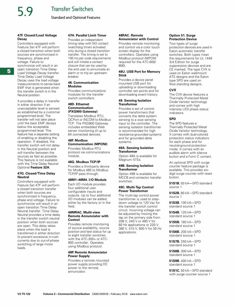
V2-T5-122 Volume 2—Commercial Distribution CA08100003E—February 2018 www.eaton.com
5
5
5
5
5
5
5
5
5
5
5
5
5
5
5
5
5
5
5
5
5
5
5
5
5
5
5
5
5
5
5.9 Transfer Switches
Standard and Optional Features
47F. Closed/Load Voltage Decay
Controllers equipped with Feature Set 47F will perform a closed transition when both sources are synchronized in frequency, phase and voltage. Failure to synchronize will result in an open transition Time Delay Load Voltage Decay transfer. Time Delay Load Voltage Decay uses the load voltage measurements to sense back EMF that is generated when the transfer switch is in the Neutral position.
It provides a delay in transfer in either direction if an unacceptable level is sensed as established by a customer programmed level. The transfer will not take place until the back EMF decays below the acceptable programmed level. This feature has a separate setting of enabling or disabling the operation. If disabled, the transfer switch will not delay in the Neutral position and will transfer between the sources as fast as possible. This feature is not available with the Time Delay Neutral Optional Feature 32A.
47G. Closed/Time Delay Neutral
Controllers equipped with Feature Set 47F will perform a closed transition transfer when both sources are synchronized in frequency, phase and voltage. Failure to synchronize will result in an open transition Time Delay Neutral transfer. Time Delay Neutral provides a time delay in the transfer switch neutral position when both sources are open. This delay takes place when the load is transferred in either direction to prevent excessive in-rush currents due to out-of-phase switching of large motor loads.
47H. Parallel Limit Timer
Provides an independent timing relay with NO contact (watchdog timer) activated only during a closed transition transfer. The timing is set to 100 ms per code requirements and will initiate a contact closure that can be used by the end user to annunciate an alarm or to trip an upstream breaker.
48. Communication Modules
Provides communications modules for the transfer switch controllers.
48D. EthernetCommunication (PXG900 Gateway)
Translates Modbus RTU, QCPort or INCOM to Modbus TCP. The PXG900 Gateway includes embedded Web server monitoring of up to 64 connected devices.
48F. ModbusCommunication (MPONI)
Provides Modbus RTU protocol via communications module.
48G. Modbus TCP/IP
Provides a third-party device for Modbus 485 to Modbus TCP/IP pass through.
48M1–48M4. I/O Module
Each I/O module provides four additional user configurable inputs and outputs. Up to four additional I/O modules can be added, either by the factory or in the field.
48MRAC. Multi-view Remote Annunciator with Control
Provides remote monitoring of source availability, source position and test status for up to eight transfer switches with the ATC-300+ or ATC-900 controller. Operates using Modbus protocol.
48P. Remote Annunciator Power Supply
Provides a remote mounted power supply providing DC power to the remote annunciator.
48RAC. Remote Annunciator with Control
Provides remote monitoring and control via a color touch screen display for the controllers. Operates using Modbus protocol (MPONI required for the ATC-600/800).
48U. USB Port for Memory Stick
Provides a device panel mounted USB port for uploading or downloading controller set points and for downloading event history.
49. Sensing Isolation Transformer
Provides a set of control power transformers that converts the delta system sensing to a wye sensing input to the controller. The sensing isolation transformer is recommended for high resistance grounded systems and for grounded delta systems.
49A. Sensing Isolation Transformer
Option 49A is available for Magnum ATSs.
49B. Sensing Isolation Transformer
Option 49B is available for MCCB and contactor transfer switches.
49C. Multi-Tap Control Power Transformer
The multi-tap control power transformer is used to step-down voltage to 120 Vac for the transfer switch control circuit. Incoming voltage can be adjusted by moving the tap on the primary side from 208 V, 240 V or 480 V for 60 Hz applications or 220 V, 380 V, 415 V, 600 V for 50 Hz applications.
Option 51. Surge Protection Device
Two types of surge protection devices are used in Eaton automatic transfer switches. Both types meet the requirements for UL 1449 3rd Edition for surge suppression devices and are CE marked. The type CVX is used on Eaton wallmount ATS designs and the Eaton type SPD are used on floor-standing designs.
CVX
The CVX device features a Thermally Protected Metal Oxide Varistor technology and comes with high intensity LED phase status indicators.
SPD
The SPD features a Thermally Protected Metal Oxide Varistor technology. It comes with dual-colored protection status indicators for each phase and for neutral-ground protection mode. It comes with an audible alarm with silence button and a Form C contact.
An optional SPD with surge counter feature package is available. This provides six-digit surge counter with reset button.
51S1B. 50 kA—SPD standard source 1
51S2B. 80 kA—SPD standard source 1
51S3B. 100 kA—SPD standard source 1
51S4B. 120 kA—SPD standard source 1
51S5B. 160 kA—SPD standard source 1
51S6B. 200 kA—SPD standard source 1
51S7B. 250 kA—SPD standard source 1
51S8B. 300 kA—SPD standard source 1
51S9B. 400 kA—SPD standard source 1
51S1C. 50 kA—SPD standard with surge counter source 1
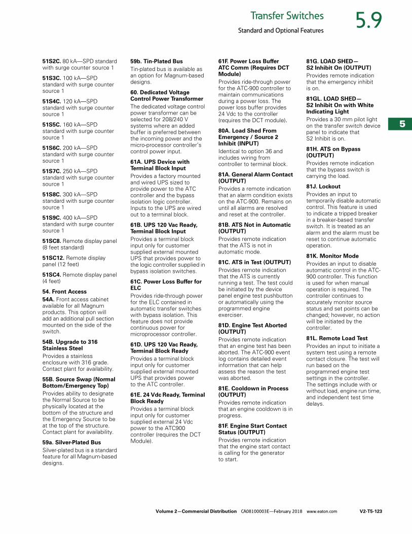
Volume 2—Commercial Distribution CA08100003E—February 2018 www.eaton.com V2-T5-123
5
5
5
5
5
5
5
5
5
5
5
5
5
5
5
5
5
5
5
5
5
5
5
5
5
5
5
5
5
5
5.9Transfer Switches
Standard and Optional Features
51S2C. 80 kA—SPD standard with surge counter source 1
51S3C. 100 kA—SPD standard with surge counter source 1
51S4C. 120 kA—SPD standard with surge counter source 1
51S5C. 160 kA—SPD standard with surge counter source 1
51S6C. 200 kA—SPD standard with surge counter source 1
51S7C. 250 kA—SPD standard with surge counter source 1
51S8C. 300 kA—SPD standard with surge counter source 1
51S9C. 400 kA—SPD standard with surge counter source 1
51SC8. Remote display panel (8 feet standard)
51SC12. Remote display panel (12 feet)
51SC4. Remote display panel (4 feet)
54. Front Access
54A. Front access cabinet available for all Magnum products. This option will add an additional pull section mounted on the side of the switch.
54B. Upgrade to 316 Stainless Steel
Provides a stainless enclosure with 316 grade. Contact plant for availability.
55B. Source Swap (Normal Bottom/Emergency Top)
Provides ability to designate the Normal Source to be physically located at the bottom of the structure and the Emergency Source to be at the top of the structure. Contact plant for availability.
59a. Silver-Plated Bus
Silver-plated bus is a standard feature for all Magnum-based designs.
59b. Tin-Plated Bus
Tin-plated bus is available as an option for Magnum-based designs.
60. Dedicated Voltage Control Power Transformer
The dedicated voltage control power transformer can be selected for 208/240 V systems where an added buffer is preferred between the incoming power and the micro-processor controller’s control power input.
61A. UPS Device with Terminal Block Input
Provides a factory mounted and wired UPS sized to provide power to the ATC controller and the bypass isolation logic controller. Inputs to the UPS are wired out to a terminal block.
61B. UPS 120 Vac Ready, Terminal Block Input
Provides a terminal block input only for customer supplied external mounted UPS that provides power to the logic controller supplied in bypass isolation switches.
61C. Power Loss Buffer for ELC
Provides ride-through power for the ELC contained in automatic transfer switches with bypass isolation. This feature does not provide continuous power for microprocessor controller.
61D. UPS 120 Vac Ready, Terminal Block Ready
Provides a terminal block input only for customer supplied external mounted UPS that provides power to the ATC controller.
61E. 24 Vdc Ready, Terminal Block Ready
Provides a terminal block input only for customer supplied external 24 Vdc power to the ATC900 controller (requires the DCT Module).
61F. Power Loss Buffer ATC Comm (Requires DCT Module)
Provides ride-through power for the ATC-900 controller to maintain communications during a power loss. The power loss buffer provides 24 Vdc to the controller (requires the DCT module).80A. Load Shed From Emergency / Source 2 Inhibit (INPUT)
Identical to option 36 and includes wiring from controller to terminal block.
81A. General Alarm Contact (OUTPUT)
Provides a remote indication that an alarm condition exists on the ATC-900. Remains on until all alarms are resolved and reset at the controller.
81B. ATS Not in Automatic (OUTPUT)
Provides remote indication that the ATS is not in automatic mode.
81C. ATS in Test (OUTPUT)
Provides remote indication that the ATS is currently running a test. The test could be initiated by the device panel engine test pushbutton or automatically using the programmed engine exerciser.
81D. Engine Test Aborted (OUTPUT)
Provides remote indication that an engine test has been aborted. The ATC-900 event log contains detailed event information that can help assess the reason the test was aborted.
81E. Cooldown in Process (OUTPUT)
Provides remote indication that an engine cooldown is in progress.
81F. Engine Start Contact Status (OUTPUT)
Provides remote indication that the engine start contact is calling for the generator to start.
81G. LOAD SHED—S2 Inhibit On (OUTPUT)
Provides remote indication that the emergency inhibit is on.
81GL. LOAD SHED—S2 Inhibit On with White Indicating Light
Provides a 30 mm pilot light on the transfer switch device panel to indicate that S2 Inhibit is on.
81H. ATS on Bypass (OUTPUT)
Provides remote indication that the bypass switch is carrying the load.
81J. Lockout
Provides an input to temporarily disable automatic control. This feature is used to indicate a tripped breaker in a breaker-based transfer switch. It is treated as an alarm and the alarm must be reset to continue automatic operation.
81K. Monitor Mode
Provides an input to disable automatic control in the ATC-900 controller. This function is used for when manual operation is required. The controller continues to accurately monitor source status and set points can be changed; however, no action will be initiated by the controller.
81L. Remote Load Test
Provides an input to initiate a system test using a remote contact closure. The test will run based on the programmed engine test settings in the controller. The settings include with or without load, engine run time, and independent test time delays.
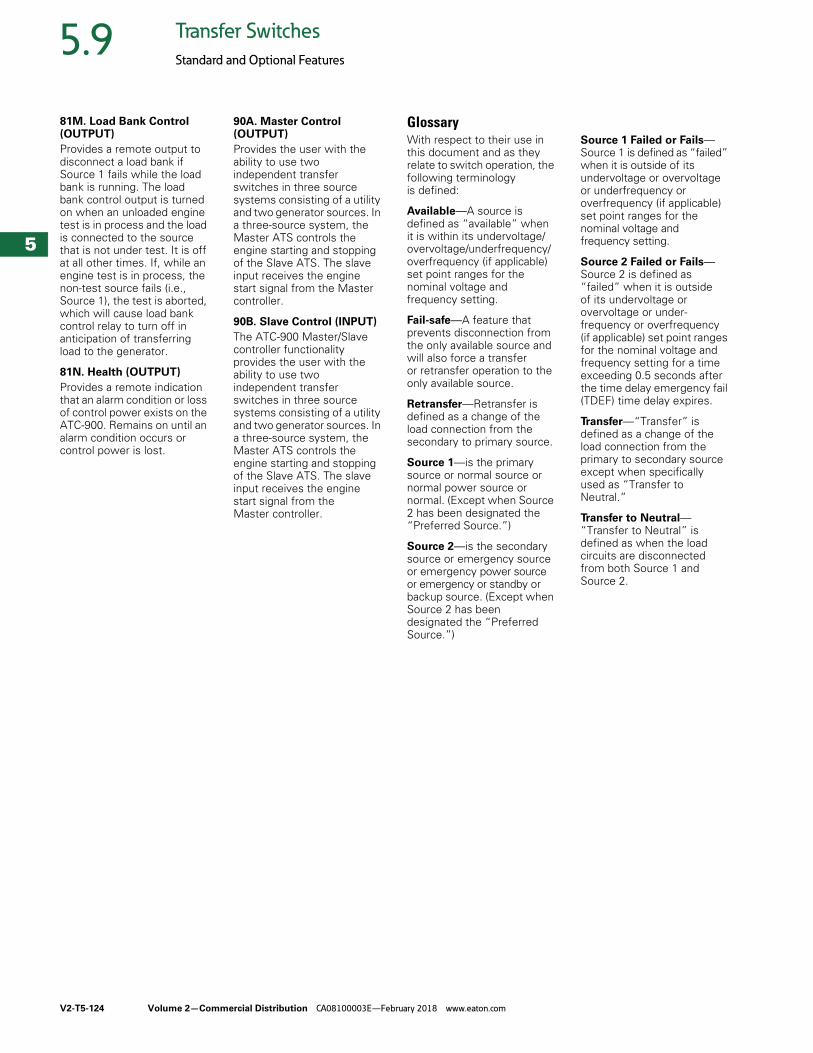
V2-T5-124 Volume 2—Commercial Distribution CA08100003E—February 2018 www.eaton.com
5
5
5
5
5
5
5
5
5
5
5
5
5
5
5
5
5
5
5
5
5
5
5
5
5
5
5
5
5
5
5.9 Transfer Switches
Standard and Optional Features
81M. Load Bank Control (OUTPUT)
Provides a remote output to disconnect a load bank if Source 1 fails while the load bank is running. The load bank control output is turned on when an unloaded engine test is in process and the load is connected to the source that is not under test. It is off at all other times. If, while an engine test is in process, the non-test source fails (i.e., Source 1), the test is aborted, which will cause load bank control relay to turn off in anticipation of transferring load to the generator.
81N. Health (OUTPUT)
Provides a remote indication that an alarm condition or loss of control power exists on the ATC-900. Remains on until an alarm condition occurs or control power is lost.
90A. Master Control (OUTPUT)
Provides the user with the ability to use two independent transfer switches in three source systems consisting of a utility and two generator sources. In a three-source system, the Master ATS controls the engine starting and stopping of the Slave ATS. The slave input receives the engine start signal from the Master controller.
90B. Slave Control (INPUT)
The ATC-900 Master/Slave controller functionality provides the user with the ability to use two independent transfer switches in three source systems consisting of a utility and two generator sources. In a three-source system, the Master ATS controls the engine starting and stopping of the Slave ATS. The slave input receives the engine start signal from the Master controller.
GlossaryWith respect to their use in this document and as they relate to switch operation, the following terminology is defined:
Available—A source is defined as “available” when it is within its undervoltage/overvoltage/underfrequency/overfrequency (if applicable) set point ranges for the nominal voltage and frequency setting.
Fail-safe—A feature that prevents disconnection from the only available source and will also force a transfer or retransfer operation to the only available source.
Retransfer—Retransfer is defined as a change of the load connection from the secondary to primary source.
Source 1—is the primary source or normal source or normal power source or normal. (Except when Source 2 has been designated the “Preferred Source.”)
Source 2—is the secondary source or emergency source or emergency power source or emergency or standby or backup source. (Except when Source 2 has been designated the “Preferred Source.”)
Source 1 Failed or Fails—Source 1 is defined as “failed” when it is outside of its undervoltage or overvoltage or underfrequency or overfrequency (if applicable) set point ranges for the nominal voltage and frequency setting.
Source 2 Failed or Fails—Source 2 is defined as “failed” when it is outside of its undervoltage or overvoltage or under-frequency or overfrequency (if applicable) set point ranges for the nominal voltage and frequency setting for a time exceeding 0.5 seconds after the time delay emergency fail (TDEF) time delay expires.
Transfer—“Transfer” is defined as a change of the load connection from the primary to secondary source except when specifically used as “Transfer to Neutral.”
Transfer to Neutral—“Transfer to Neutral” is defined as when the load circuits are disconnected from both Source 1 and Source 2.
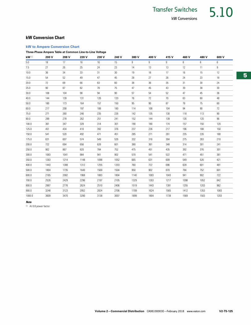
Volume 2—Commercial Distribution CA08100003E—February 2018 www.eaton.com V2-T5-125
5
5
5
5
5
5
5
5
5
5
5
5
5
5
5
5
5
5
5
5
5
5
5
5
5
5
5
5
5
5
5.10Transfer Switches
kW Conversions
kW Conversion Chart
kW to Ampere Conversion Chart
Note1 At 0.8 power factor.
Three-Phase Ampere Table at Common Line-to-Line Voltage
kW 1 200 V 208 V 220 V 230 V 240 V 380 V 400 V 415 V 460 V 480 V 600 V
5.0 18 17 16 16 15 9 9 9 8 8 6
7.5 27 26 25 24 23 14 13 13 12 11 9
10.0 36 34 33 31 30 19 18 17 16 15 12
15.0 54 52 49 47 45 28 27 26 24 23 18
20.0 72 69 66 63 60 38 36 35 31 30 24
25.0 90 87 82 78 75 47 45 43 39 38 30
30.0 108 104 98 94 90 57 54 52 47 45 36
40.0 144 139 131 126 120 76 72 70 63 60 48
50.0 180 173 164 157 150 95 90 87 78 75 60
60.0 217 208 197 188 180 114 108 104 94 90 72
75.0 271 260 246 235 226 142 135 130 118 113 90
80.0 289 278 262 251 241 152 144 139 126 120 96
100.0 361 347 328 314 301 190 180 174 157 150 120
125.0 451 434 410 392 376 237 226 217 196 188 150
150.0 541 520 492 471 451 285 271 261 235 226 180
175.0 631 607 574 549 526 332 316 304 275 263 210
200.0 722 694 656 628 601 380 361 348 314 301 241
250.0 902 867 820 784 752 475 451 435 392 376 301
300.0 1083 1041 984 941 902 570 541 522 471 451 361
350.0 1263 1214 1148 1098 1052 665 631 609 549 526 421
400.0 1443 1388 1312 1255 1203 760 722 696 628 601 481
500.0 1804 1735 1640 1569 1504 950 902 870 784 752 601
600.0 2165 2082 1968 1883 1804 1140 1083 1043 941 902 722
700.0 2526 2429 2296 2197 2105 1329 1263 1217 1098 1052 842
800.0 2887 2776 2624 2510 2406 1519 1443 1391 1255 1203 962
900.0 3248 3123 2952 2824 2706 1709 1624 1565 1412 1353 1083
1000.0 3609 3470 3280 3138 3007 1899 1804 1739 1569 1503 1203