Volume 2 Engineering Design for Development › files › assets › ... · Volume 2 Engineering...
213
Transcript of Volume 2 Engineering Design for Development › files › assets › ... · Volume 2 Engineering...


Volume 2 Engineering Design for Development
ii Campbelltown (Sustainable City) Development Control Plan 2009 Effective 24 June 2009

Volume 2 Engineering Design for Development
Campbelltown (Sustainable City)
Development Control Plan 2009
Volume 2 Engineering Design for Development
- June 2009 -
Table of Contents CONTENTS PAGE NO. FOREWORD...................................................................................................................................... 1 GLOSSARY........................................................................................................................................ 5 1. GENERAL PROCEDURES................................................................................................... 9
1.1 Scope ....................................................................................................................... 9 1.2 Aim ........................................................................................................................... 9 1.3 Engineering Plans & Accredited Certifiers ............................................................... 9 1.4 Overview of Engineering Process for the Applicant................................................. 9 1.5 Engineering Survey & Bench Marks ...................................................................... 12 1.6 Engineering Drawings ............................................................................................ 13 1.7 Persons Qualified................................................................................................... 13 1.8 Consultation ........................................................................................................... 13 1.9 Inspection of Works................................................................................................ 13 1.10 Vegetation Preservation......................................................................................... 14 1.11 Street Trees............................................................................................................ 14 1.12 Erosion and Sediment Control ............................................................................... 14 1.13 Road Safety Audit and OH&S Requirements ........................................................ 14 1.14 Bonds ..................................................................................................................... 15
1.14.1 General...................................................................................................... 15 1.14.2 Footpath Paving ........................................................................................ 15 1.14.3 Maintenance.............................................................................................. 15
1.15 Contributions/Monetary Payments......................................................................... 15 1.15.1 A.C. Sealing .............................................................................................. 15 1.15.2 Street Trees .............................................................................................. 16 1.15.3 Footpath Paving ........................................................................................ 16 1.15.4 Other Section 94 Contributions................................................................. 16
1.16 Work-As-Executed (W.A.E.) Plans......................................................................... 16 1.17 Certificates, Diagrams and Slope Junction Plans ................................................. 18 1.18 Written Consents.................................................................................................... 18 1.19 Street Lighting ........................................................................................................ 18
1.19.1 Council’s Guidelines.................................................................................. 18 1.19.2 The Lighting of Arterial and Sub-Arterial Roads ....................................... 18 1.19.3 The Lighting of Residential Roads and Public Places .............................. 19 1.19.4 Subdivision................................................................................................ 19 1.19.5 Pathways................................................................................................... 19 1.19.6 Traffic Management Devices .................................................................... 19 1.19.7 Proposed Schemes................................................................................... 19
2. ENGINEERING DRAWINGS .............................................................................................. 21 2.1 Scope ..................................................................................................................... 21 2.2 Aim ......................................................................................................................... 21 2.3 General Requirements ........................................................................................... 21 2.4 Road and Drainage Drawings................................................................................ 21
iii Campbelltown (Sustainable City) Development Control Plan 2009 Effective 24 June 2009

Volume 2 Engineering Design for Development
2.5 Stormwater Management Drawings ....................................................................... 22 2.6 Title Blocks ............................................................................................................. 22 2.7 Title Sheet/Layout Plan .......................................................................................... 22 2.8 Detail Plans............................................................................................................. 22 2.9 Road Long Sections ............................................................................................... 24 2.10 Road Cross Section(s) ........................................................................................... 24 2.11 Typical Road Cross Section(s) ............................................................................... 24 2.12 Kerb Return, Cul-de-sac and Splay Corner Details................................................ 25 2.13 Traffic Calming Devices, Median Islands and Other Miscellaneous Road Details 25 2.14 Pathways ................................................................................................................ 26 2.15 Stormwater Catchment Plan................................................................................... 26 2.16 Drainage Calculations ............................................................................................ 26 2.17 Drainage Longitudinal Section(s) ........................................................................... 26 2.18 Other Stormwater Details ....................................................................................... 27 2.19 Easement Widths ................................................................................................... 28 2.20 Overland Flow Paths .............................................................................................. 28
2.20.1 Subdivisions .............................................................................................. 28 2.20.2 Site Developments .................................................................................... 28 2.20.3 Restrictions/Positive Covenants................................................................ 28
2.21 Retaining Walls....................................................................................................... 29 2.22 Erosion and Sediment Control Measures............................................................... 29 2.23 Traffic Control Measures ........................................................................................ 29 2.24 Adjoining Owners Permission................................................................................. 29 2.25 Work-As-Executed Plans for Engineering Works................................................... 30 2.26 Sheet Sizes............................................................................................................. 30 2.27 Scales ..................................................................................................................... 30 2.28 Dimensions ............................................................................................................. 30
3. ROAD DESIGN.................................................................................................................... 31 3.1 Scope...................................................................................................................... 31 3.2 Aim.......................................................................................................................... 31 3.3 Planning Standards ................................................................................................ 31 3.4 Half Width Roads.................................................................................................... 33 3.5 Construction Specification ...................................................................................... 34 3.6 Pavement Design ................................................................................................... 34 3.7 Pavement Surfacing ............................................................................................... 36 3.8 Geometric Design - General Principles .................................................................. 36 3.9 Design Speed ......................................................................................................... 37 3.10 Sight Distance......................................................................................................... 37 3.11 Horizontal Alignment .............................................................................................. 38 3.12 Transitions and Widening on Curves ..................................................................... 38 3.13 Longitudinal Gradient ............................................................................................. 38 3.14 Vertical Curves ....................................................................................................... 39 3.15 Super-Elevation ...................................................................................................... 40 3.16 Carriageway Crossfall ............................................................................................ 40 3.17 Kerb and Gutter ...................................................................................................... 40 3.18 Cycleways and Footpath Paving ............................................................................ 40 3.19 Berms ..................................................................................................................... 43 3.20 Batters .................................................................................................................... 43 3.21 Intersections ........................................................................................................... 43 3.22 Kerb Returns, Laybacks and Wheelchair Crossings.............................................. 44 3.23 Battle-axe Handles ................................................................................................. 45 3.24 Cul-De-Sac Head Kerb Grading ............................................................................. 45 3.25 Roundabouts .......................................................................................................... 45 3.26 Traffic Calming Devices.......................................................................................... 46 3.27 Street Furniture....................................................................................................... 46 3.28 Traffic Control for Works in Public Roads .............................................................. 46 3.29 Roundabouts and Median Strip Embellishment ..................................................... 47
3.29.1 Description................................................................................................. 47 3.29.2 Design Requirements ................................................................................ 47
iv Campbelltown (Sustainable City) Development Control Plan 2009 Effective 24 June 2009

Volume 2 Engineering Design for Development
3.30 Bridges and Culverts.............................................................................................. 48 3.31 Safety Barriers for Roads and Bridges .................................................................. 48 3.32 Residential Driveway Profile and Garage Requirements....................................... 48 3.33 Conduits/Ducts ....................................................................................................... 48
4. STORMWATER DESIGN ................................................................................................... 51 4.1 Scope ..................................................................................................................... 51 4.2 Aim ......................................................................................................................... 52 4.3 New Release Area Proposals ................................................................................ 53 4.4 Older Areas and On-site Detention (OSD)............................................................. 54 4.5 Fill and Floor Levels ............................................................................................... 55 4.6 Tailwater................................................................................................................. 56 4.7 Major Minor Philosophy.......................................................................................... 57 4.8 Design Procedure .................................................................................................. 57 4.9 Hydrology ............................................................................................................... 58
4.9.1 Rainfall IFD ............................................................................................... 58 4.9.2 Temporal Patterns..................................................................................... 58 4.9.3 Contributing Catchment ............................................................................ 58 4.9.4 Impervious Percentages ........................................................................... 59 4.9.5 Pit Capacity ............................................................................................... 59
4.10 Hydrologic Methods ............................................................................................... 60 4.10.1 Rural Unit hydrograph methods ................................................................ 60 4.10.2 Rural Rational method .............................................................................. 60 4.10.3 Urban Rational method ............................................................................. 61 4.10.4 Kinematic Wave / Time of Concentration.................................................. 61 4.10.5 Partial Area Flows ..................................................................................... 62
4.11 Computer Models................................................................................................... 62 4.12 Minor System ......................................................................................................... 63
4.12.1 Preliminary Layout of Proposed Stormwater ............................................ 65 4.12.2 Hydraulic Grade Line Analysis.................................................................. 66 4.12.3 Pipeline Design ......................................................................................... 67 4.12.4 General Requirements for Pipelines ......................................................... 68 4.12.5 Pit Design.................................................................................................. 69 4.12.6 Culvert Design........................................................................................... 71
4.13 Major System ......................................................................................................... 72 4.13.1 PMF Requirements ................................................................................... 73 4.13.2. Floodways and Channels.......................................................................... 73 4.13.3 Determination of Water Surface Levels .................................................... 75 4.13.4 Major Flows in Roadways ......................................................................... 76 4.13.5 Major Flow in Parks and Pathways........................................................... 77 4.13.6 Major Structures........................................................................................ 79 4.13.7 Detention Basins ....................................................................................... 79 4.13.8 Underground Car Parks ............................................................................ 81 4.13.9 Landscape Requirements ......................................................................... 81
4.14 Internal Stormwater Requirements ........................................................................ 82 4.14.1 Roof Runoff ............................................................................................... 83 4.14.2 Impact on Adjoining Properties ................................................................. 83 4.14.3 Sites Affected by Overland Flow............................................................... 83 4.14.4 Internal Stormwater Pits............................................................................ 84 4.14.5 Internal Stormwater Pipes......................................................................... 84 4.14.6 Silt/Oil Arrestors and Trash Screens......................................................... 85 4.14.7 Subsoil Drainage....................................................................................... 85 4.14.8 Stormwater Disposal to Council's System ................................................ 85 4.14.9 Inter-allotment Drainage............................................................................ 87 4.14.10 Alternative Solutions ................................................................................. 89
4.15 Stormwater Quality................................................................................................. 90 4.16 Water Sensitive Urban Design............................................................................... 91 4.17 Drainage Easements.............................................................................................. 97 4.18 Public Safety – Stormwater and Drainage Easements.......................................... 99
4.18.1 Public Safety – Physical............................................................................ 99
v Campbelltown (Sustainable City) Development Control Plan 2009 Effective 24 June 2009

Volume 2 Engineering Design for Development
4.18.2 Public Safety – Criminal ..........................................................................102
4.19 Rainwater Tanks...................................................................................................102 4.20 Visual Impact ........................................................................................................103 4.21 Froude Value ........................................................................................................103 4.22 Sensitivity Analysis ...............................................................................................103 4.23 Maintenance .........................................................................................................104 4.24 Design Life............................................................................................................104 4.25 Climate Change....................................................................................................104
5 MISCELLANEOUS REQUIREMENTS..............................................................................119 5.1 Scope....................................................................................................................119 5.2 Aim........................................................................................................................119 5.3 Lot Cutting and Filling...........................................................................................119 5.4 Safety Notation .....................................................................................................121 5.5 Debris Disposal.....................................................................................................122 5.6 Insurance ..............................................................................................................122 5.7 Fencing and Retaining Walls................................................................................122 5.8 Salinity ..................................................................................................................123 5.9 Landscaping and landscaped area.......................................................................126 5.10 Development in Mines Subsidence Areas............................................................126 5.11 Requirements for Development Applications for Industrial Development............127 5.12 Garbage Restriction..............................................................................................127 5.13 Emergency Vehicle Access ..................................................................................127
6 SOIL & WATER MANAGEMENT ......................................................................................130 6.1 Scope....................................................................................................................130 6.2 Aim........................................................................................................................130 6.3 Requirements for an ESCP ..................................................................................131 6.4 Erosion & Sediment Control Guidelines for Building Sites...................................131 6.5 Maintenance of Erosion and Sediment Control Measures...................................133
Appendix A Checklist for Engineering Plans ..................................................................................135 Appendix B Stormwater Information...............................................................................................149 Appendix C Flood Proofing Requirements .....................................................................................165 Appendix D Guidelines for Flood Analysis Involving Overland Flow..............................................173 Appendix E Bank guarantees and cash security Documents Format & Instructions .....................177 Appendix F Restriction as to User (RATU).....................................................................................182 Appendix G Example Easement Certificate ...................................................................................186 Appendix H Planting in Drainage Easements ................................................................................188 Appendix I Street Lighting Management Guidelines ......................................................................192 Appendix J Document History ........................................................................................................198 Appendix K Standard Drawings......................................................................................................202
vi Campbelltown (Sustainable City) Development Control Plan 2009 Effective 24 June 2009

Volume 2 Engineering Design for Development
Campbelltown (Sustainable City)
Development Control Plan 2009
Volume 2 Engineering Design for Development
- June 2009 -
List of Tables TABLE PAGE NO. Table 3.1 Campbelltown City Council – Subdivision Road Network Design Characteristics 32 Table 3.2 Minimum Sight Distance (Source: Dept of Housing).............................................. 37 Table 3.3 Desirable Sight Distance........................................................................................ 37 Table 3.4 Minimum Curve Radii............................................................................................. 38 Table 3.5 Minimum/Maximum Longitudinal Grades............................................................... 38 Table 3.6 Minimum Vertical Curve Lengths ........................................................................... 39 Table 3.7 Normal Cross-fall ................................................................................................... 40 Table 3.8 Minimum Standards for Cycleways and Pathways................................................ 42 Table 3.9 Maximum Batter Slopes ......................................................................................... 43 Table 3.10 Typical Roundabout Usage (see figure on previous page).................................... 50 Table 4.1 Floor Level and Freeboard Requirements ............................................................ 56 Table 4.2 Percentage Impervious for Various Landuses....................................................... 59 Table 4.3 Pit Blockage Factors .............................................................................................. 59 Table 4.4 n* Values for Use with Kinematic Wave Equation ................................................. 62 Table 4.5 Nominal Design ARI for the Minor System ............................................................ 63 Table 4.8 Pipe Friction for Pipes ............................................................................................ 67 Table 4.9 Entrance Loss Coefficient, ke ................................................................................. 72 Table 4.10 Typical Roughness ”n" Values for Manning’s Equation. ........................................ 76 Table 4.14 Surface flow criteria for roads ................................................................................ 77 Table 4.15 Minimum Internal Dimensions for Stormwater Inlet Pits ........................................ 84 Table 4.16 Minimum Gradient of Site Stormwater Drains........................................................ 84 Table 4.17 Inter-allotment Drainage Pipe Sizes ...................................................................... 88 Table 4.18 Easement Widths ................................................................................................... 98 Table 4.6 Hydrological Design Sheet 1................................................................................ 105 Table 4.7 Hydrological Design Sheet 2................................................................................ 106 Table 4.11 Hydrological Design Sheet 3................................................................................ 107 Table 4.12 Hydrological Checking Sheet ............................................................................... 108 Table 4.13 Table for Culvert Calculations .............................................................................. 109 Table I-1 Lighting categories for local roads (extract from AS 1158).................................. 192 Table I-2 Lighting categories for traffic routes (extract from AS 1158) ............................... 193 Table I-3 Lighting categories for public activity areas (extract from AS 1158).................... 194 Table I-4 Lighting Categories .............................................................................................. 194
vii Campbelltown (Sustainable City) Development Control Plan 2009 Effective 24 June 2009

Volume 2 Engineering Design for Development
viii Campbelltown (Sustainable City) Development Control Plan 2009 Effective 24 June 2009

Volume 2 Engineering Design for Development
Campbelltown (Sustainable City)
Development Control Plan 2009
Volume 2 Engineering Design for Development
- June 2009 -
List of Figures FIGURES PAGE NO. Figure 1 Relationship of this document to other Council documents and its role in the
development process ............................................................................................................ 3 Figure 3.1 Road Hierarchy ...................................................................................................... 33 Figure 4.9 Conventional Development .vs. WSUD ................................................................ 95 Figure 4.10 End-of-Line .vs. Distributed Treatment .................................................................. 96 Figure 4.11 Zone of Influence ................................................................................................... 99 Figure 4.12 Velocity Depth Relationship ................................................................................. 101 Figure 4.1 Hydraulic Gradients.............................................................................................. 110 Figure 4.2 Pit Loss Coefficients............................................................................................. 111 Figure 4.3 Pressure Loss Coefficients cont........................................................................... 112 Figure 4.4 Grated Kerb Inlet Independent of Grade.............................................................. 113 Figure 4.5 Inlet Capacities for Kerb Inlets in Sags ................................................................ 114 Figure 4.6 Inlet Capacities for Gratings in Sags.................................................................... 115 Figure 4.7 Inlet Capacities for Kerb Inlets with Durham Type Grates in Sags...................... 116 Figure 4.8 Inlet Capacities for Kerb Inlets with Weldlok Type Grates in Sags...................... 117
ix Campbelltown (Sustainable City) Development Control Plan 2009 Effective 24 June 2009

Volume 2 Engineering Design for Development
x Campbelltown (Sustainable City) Development Control Plan 2009 Effective 24 June 2009

Volume 2 Engineering Design for Development
FOREWORD Volume 2 of the Campbelltown (Sustainable City) Development Control Plan 2009, (this Guide), and its accompanying document, Council's Specification for Construction of Subdivisional Road and Drainage Works have been prepared to provide engineering guidelines for the subdivision and development of land within the Campbelltown City Council area. Wherever discrepancies between these two documents arise, the DCP governs. Where the term “Guide” or “The Guide” is used, it refers to this document, Volume 2 of the Campbelltown (Sustainable City) Development Control Plan. The aim of the Guide is to facilitate the efficient processing of engineering plan submissions, and to ensure that infrastructure associated with any development is designed and constructed to be safe, serviceable, economical to maintain and meets community expectations. The objectives of this Guide are to:
Provide clear information to developers in terms of Council's requirements for civil works;
Ensure that developments meet all relevant standards and current best management practices;
Expedite the assessment of development applications; Clarify/update components of previous policies; Preserve and protect the amenity and property of existing residents, property
owners and the community; Provide for public safety and convenience and to protect property; Stabilise the landform and control erosion; Enhance the urban landscape; Maintain regional water quality and protect the physical environment and receiving
waters of catchments; and Provide a method for recording the design process.
This document reflects current best practise. This Guide will be revised periodically to embrace new ideas and technologies and consolidate new issues that may arise. The Guide will form a basis for uniform design practices for Engineering works. This will help to minimise delays in assessing proposals. It is accepted that individual sites may present unique problems in the use of the standardised design approaches but it is hoped that the Guide will be comprehensive enough that the majority of sites may use the approaches detailed to meet Council’s objectives. Applicants should be aware that each development is required to be treated on its merits, and that approval is dependant on the overall impact of the development and not solely on compliance with minimum engineering standards. Nothing in this Guide is to be construed as limiting, in any way, Council's rights to impose differing conditions when approving development proposals, nor limiting the discretion of Council's Manager Development Services or nominated representative to vary any necessary engineering requirements in respect of a particular development, having regard to good engineering practice.
1 Campbelltown (Sustainable City) Development Control Plan 2009 Effective 24 June 2009

Volume 2 Engineering Design for Development
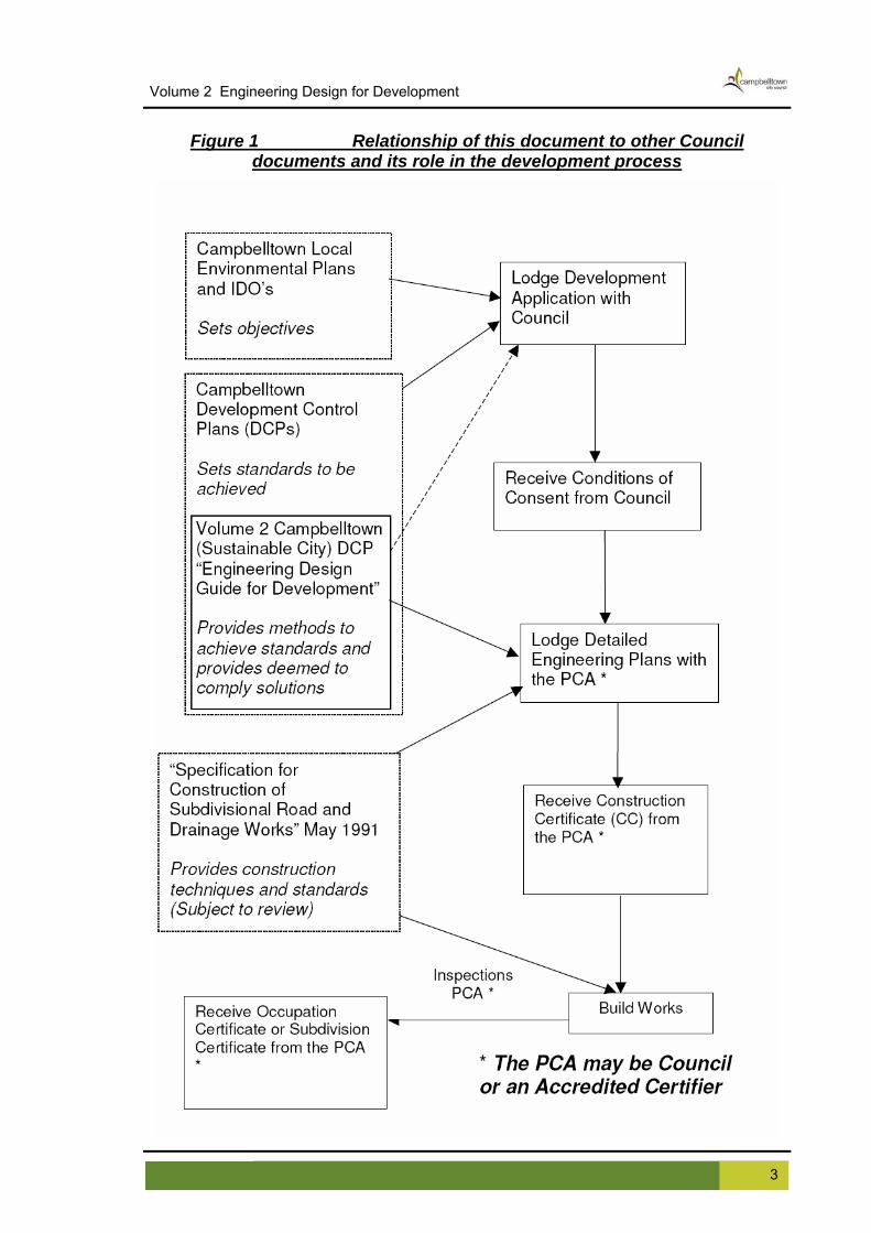
This Guide provides a common development standard which applies to Developers, Contractors undertaking work for Council and Council works undertaken by Council’s staff. It does not provide stand-alone advice and must be supplemented with information from a number of other publications which are subject to periodic review. These documents are listed throughout the document. This Guide should not in any way be interpreted as relieving the designer of the responsibility to properly assess all conditions, to use professional judgement, sound practices and the economic evaluation of alternatives as normally required in developing any design proposal. Should any departure from the requirements set out in the Guide be found necessary, Council should be informed through the Manager Development Services before completion of the design proposal in order that the proposal might be evaluated. Council wishes to acknowledge the assistance freely given by Blacktown City Council in the preparation of this Guide. Blacktown Council provided the base documents, which were used as the basis of this document and provided many of the standard drawings. In particular the assistance provided by Daniele Favotto Co-ordinator Engineering Approvals at Blacktown City Council is acknowledged. Figure 1 on the following page indicates the relationship of this document to Council’s other Planning, Design and Construction documents.
2 Campbelltown (Sustainable City) Development Control Plan 2009 Effective 24 June 2009
Volume 2 Engineering Design for Development
Figure 1 Relationship of this document to other Council
documents and its role in the development process
3 Campbelltown (Sustainable City) Development Control Plan 2009 Effective 24 June 2009

Volume 2 Engineering Design for Development
4 Campbelltown (Sustainable City) Development Control Plan 2009 Effective 24 June 2009

Volume 2 Engineering Design for Development
GLOSSARY 6:1 (H:V) Slope of 6 horizontal to 1 vertical.
AC refers to Asphaltic Concrete.
Accreditation Body in relation to matters of a particular kind means a professional association that is authorised under Section 109S of the Environmental Planning and Assessment Act, 1979 (as amended) to accredit persons as accredited certifiers in relation to those matters.
Accredited Certifier in relation to matters of a particular kind, means a person who is accredited by an accreditation body under section 109T of the Environmental Planning and Assessment Act, 1979 (as amended) in relation to those matters.
Afflux is the rise in water level in a stream or channel caused by a constriction downstream
AHD refers to Australian Height Datum and is the datum to be used for all levels
Applicant refers to any person/s, company or entity representing the owner/applicant for the purpose of constructing the Works. This may also include Council.
AR&R refers to the current edition of Australian Rainfall and Runoff published by the Institution of Engineers.
ARI refers to the Average Recurrence Interval, which means the average interval (in years) between occurrences of floods, storms and flows of a particular magnitude.
ARQ refers to Australian Runoff Quality currently in draft format prepared by the Institution of Engineers, Australia
AS is the designation used for Australian Standards published by the Standards Association of Australia and being current at the time of application.
Coordinator refers to Council's Development Assessment Co-ordinator
Council refers to Campbelltown City Council as represented by its employees
Council Engineer refers to a person approving or inspecting works on behalf of Council.
CPTED refers to Crime Prevention Through Environmental Design
DC or Consent refers to the Notice of Determination giving Subdivision or Development Consent.
DECC is the New South Wales Department of Environment and Climate Change and includes the previous Department of Environment and Conservation and parts of the previous NSW Fisheries, Department of Natural Resources, The Department of Primary Industries and the NSW Greenhouse Office.
Development Engineer refers to Council’s Development Engineer unless otherwise stated
Development Supervisor refers to the person carrying out the day-to-day inspections on behalf of Council.
Documents refers to all expressed and implied Specifications, Standards, Drawings and Correspondence, which are related to the works and referred to by Council or issued by Council.
DoP is the New South Wales Department of Planning
5 Campbelltown (Sustainable City) Development Control Plan 2009 Effective 24 June 2009
Volume 2 Engineering Design for Development
DWE is the New South Wales Department of Water and Energy and includes the previous Department of Energy, Utilities and Sustainability and parts of the previous Department of Natural Resources.
Engineer or Registered Engineer refers to a person who is a practising Engineer registered on the Institution of Engineers Australia, National Professional Engineers Register (NPER) in the relevant field of work.
EP&A Act refers to the New South Wales Environmental Planning and Assessment Act 1979, as amended.
Flow path - when it rains, water that is not absorbed into the soil flows over the land toward receiving water, such as a creek, river or bay. The water follows a path where it moves from the highest point to the lowest point; this path is known as a “flow path”.
FRC pipe refers to Fibre Reinforced Concrete pipe.
Freeboard is a factor of safety used in relation to the setting of floor levels. It makes allowance for wave action, localised hydraulic behaviour and system blockages
Guide refers to this document, the Campbelltown City Council Engineering Guide for Development 2004.
Maintenance Period refers to a minimum of six (6) months after the issue of the Subdivision Certificate or practical completion of the civil works (including bonded works) whichever happens last, or such time as Council deems reasonable for the Final Acceptance of Works.
MGA refers to Map Grid of Australia and is the coordinate system to be used for all coordinates on plans
NATA refers to the National Association of Accredited Testing Authorities.
OH&S refers to requirements under the Occupational Health & Safety Act 2000 (as amended).
OSD refers to On-site Stormwater Detention.
PCA refers to the Principle Certifying Authority and may be Council or an Accredited Certifier appropriately accredited by an Accreditation Body. Probable Maximum Flood (PMF) means the largest flood that could conceivably occur at a particular location as a result of the PMP (generally considered to be equivalent to the 1 in 10,000 year event)
Probable Maximum Precipitation (PMP) means the greatest depth of precipitation meteorologically possible for a given duration for a given size storm area at a particular location at a particular time of year
Qualified Surveyor means a person who has undertaken formal tertiary qualifications in the field of surveying
PSD means Permissible Site Discharge
RCP refers to Reinforced Concrete Pipe
RTA refers to the New South Wales Roads & Traffic Authority
Section 149 Certificates or S149 Certificates refer to Clause 279 of the Environment Planning and Assessment Regulation 2000 which prescribes the matters to be specified in a planning certificate under Section 149(2) of the Environment Planning and Assessment Act 1979.
Site refers to the area of land being developed under the Subdivision or Development Approval.
6 Campbelltown (Sustainable City) Development Control Plan 2009 Effective 24 June 2009

Volume 2 Engineering Design for Development
SQID refers to a Stormwater Quality Improvement Device.
Superintendent refers to the person appointed by the Applicant to supervise the construction Works and to represent the Applicant.
Surveyor refers to a Registered Surveyor.
UPVC refers to an Unplasticised Polyvinyl Chloride (pipe).
VCP refers to a Vitrified Clay Pipe.
WAE refers to the Works as Executed Plan.
Works refers to the development of land as described by the Drawings and Specifications (the Documents) as proposed by the Applicant and as cited and approved by Council "For Construction" including all the area of the land being developed.
WSUD refers to Water Sensitive Urban Design.
7 Campbelltown (Sustainable City) Development Control Plan 2009 Effective 24 June 2009

Volume 2 Engineering Design for Development
8 Campbelltown (Sustainable City) Development Control Plan 2009 Effective 24 June 2009

Volume 2 Engineering Design for Development
1. GENERAL PROCEDURES 1.1 Scope This section of the Engineering Guide sets out Council's general procedures and practices in respect of engineering requirements for subdivision and development of all land within the Council area. 1.2 Aim To provide an Applicant with an outline of Council's engineering procedures for subdivisions and developments to limit general enquiries. 1.3 Engineering Plans & Accredited Certifiers In this Guide, whenever the term "Engineering Plan" is used, this is deemed to also be a reference to engineering plans associated with Construction Certificates issued by Council or Private Accredited Certifiers under the EP&A Act (1979), and Engineering Approvals issued by Council under the Roads Act 1993 and Local Government Act 1993. Accredited Certifiers may issue Construction and Compliance Certificates for development works and Construction Certificates for subdivision works in accordance with the EP&A Act (1979 as amended). Accredited Certifiers do not have the authority to issue Construction Certificates or Compliance Certificates for any work within a public area. It should also be noted that Construction Certificates cannot be issued for works on sites that are not part of the "subject land" for which the Development Consent has been issued. An example is inter-allotment drainage through adjacent lots that are not included in the "subject land". In this case, a separate Section 68 Local Government Act 1993 Approval would be required for the drainage works. This approval can only be issued by Council. Private Accredited Certifiers must comply with all the requirements of this Guide prior to issuing any Construction or Compliance Certificates under the EP&A Act 1979. 1.4 Overview of Engineering Process for the Applicant This section of the Guide sets out the suggested steps an Applicant should follow once a Notice of Determination giving Development Consent for a development has been issued by Council. A Read Notice of Determination (Development Consent): Where you are unsure of the meaning or extent of any condition, contact the Council and seek clarification. (Development Consent No./File No. will help in this instance.) Note: Construction Certificates cannot be issued until all Pre-Construction Certificate requirements/conditions of the Development Consent have been satisfied.
9 Campbelltown (Sustainable City) Development Control Plan 2009 Effective 24 June 2009

Volume 2 Engineering Design for Development
B Engage an Engineering Consultant/Project Manager: Satisfy yourself that the consultant has the required expertise and do not decide on your consultant simply on the basis of fees. A higher fee may result in substantial savings in approval time/construction costs due to the consultant's expertise. C Give the consultant a copy of the whole of the Notice of Determination: Any approved plans or other documents should also be given to the consultant so he/she can fully understand the project. D Let the consultant do the work: Once the consultant has been engaged, Council's officers will have only one contact who is co-ordinating the progress of your development. Time delays often arise where inexperienced Applicants try to share the project management role. E Engineering plans are prepared by the consultant: The consultant is to arrange survey and engineering designs that will fulfil the conditions of consent. These plans, when approved, will be used by the contractor to construct the works. F Lodge Engineering Plans with Council for approval and pay assessment and inspection fees: Lodge Engineering Plans, together with any other documents /calculations/information and/or any clearances from government authorities required to satisfy the conditions of consent. Council's Development Engineer will notify the applicant of the engineering fees. Once this fee has been paid, Council's Development Engineer will assess the Engineering Plans to ensure compliance with conditions of consent and other Council requirements. G Engineering plans returned to consultant for amendment (if required): The Consultant will be advised if any amendments are required to the Engineering Plans, and if any other outstanding items are required prior to the release of approved Engineering Plans. H Engineering plans re-lodged with Council: The Consultant should have carried out all the amendments required by Council. If the consultant needs clarification of any requirements, Council's Development Engineers are available for discussion. The Consultant must also ensure that Council's "Red Mark Up" Plan (showing required corrections) is returned to Council with the amended plans. This will expedite their assessment. I Engineering plans approved: When Council is satisfied that the engineering plans will enable work to be constructed with a minimum of field supervision the plans are approved and issued in accordance with the Consent conditions.
10 Campbelltown (Sustainable City) Development Control Plan 2009 Effective 24 June 2009

Volume 2 Engineering Design for Development
J Road Occupancy It is a legal requirement under Section 138 of the Roads Act to obtain a roads authority approval for works undertaken in a dedicated public road that will cause interference or obstruction to the normal use of the road by any road user and requires the operation of a traffic guidance scheme as indicated by Australian Standards, AS 1742.3. A separate application shall be made to Council for either a Road Occupancy approval, Standing Plant permit or a Road Opening approval. Works in a public road includes work in the footpath and nature strip areas. A further application for road occupancy is required to the RTA when occupancies may impact upon a classified road (state roads) or Council’s regional roads. A Vehicle Management Plan (VMP) is required to be submitted to Council for approval where there is an impact from adjacent development on public traffic. Guidelines on the need for VMP's can be referred to Section 7 of the RTA' Traffic Control at Work Sites Manual. A road occupancy application is required at any time where Traffic Controllers are being used. Refer to Section 3.28 for details. K Construction of Works: The Consultant/Applicant will engage a contractor to carry out the works in accordance with the approved plans. Council's Development Engineer or Development Supervisor will inspect the work to ensure the contractor carries the work out in accordance with the approved plans and with Council's "Specification for Construction of Subdivisional Road and Drainage Works”. L Lodge Work-As-Executed Plan: Together with any Hydraulic, Structural or Compliance Certificates, prior to requesting the final inspection. M Preliminary final inspection: When the Applicant considers the works to be complete, Council's Development Engineer / Development Supervisor will inspect the work and any defects will be brought to the Applicant's attention for rectification. N Final inspection: When all the defects, identified in the Preliminary Final Inspection, are rectified the Applicant is to request a Final Inspection. Council's Development Engineer/Development Supervisor will reinspect the work to confirm that all the defects have been rectified. O Check Notice of Determination Before requesting the issue of a Subdivision Certificate (in the case of subdivisions) or in other cases prior to the issue of an Occupation Certificate for the development, the
11 Campbelltown (Sustainable City) Development Control Plan 2009 Effective 24 June 2009

Volume 2 Engineering Design for Development
development consent must be checked in detail. The Consultant/Applicant must ensure all conditions have been satisfied including, but not limited to:
Compliance with all engineering conditions required by the Development Consent; Payment of fees and contributions; Lodgement of completed Deed of Agreement for bonded works; Lodgement of certificates as required; Lodgement of a Work-As-Executed Plan; and Lodgement of Hydraulic & Structural certificates.
P Issue of Subdivision Certificate/Occupation Certificate: When all engineering conditions of consent have been satisfied and the plan of subdivision and accompanying legal documents are correct, Council's Development Engineer for the project will recommend release of the plan of subdivision. The plan will only be released by Council if all conditions of consent have been satisfied and/or securities have been lodged for outstanding works. Q Defects Liability/Maintenance Period: (a) Subdivisions: Upon the issue of a Subdivision Certificate the constructed civil engineering work will enter the Maintenance Period. During this period any defect which becomes evident will be the responsibility of the Applicant to rectify. The Maintenance Period lasts for at least six months from the issue of the Subdivision Certificate or practical completion of the bonded works, whichever happens last. At the end of the Maintenance Period, after any defects have been rectified, the Bond will be released by Council upon written request. (b) All Other Development: Upon a clearance of road and/or drainage works at the Final Inspection (Step M), the constructed work will come under a Maintenance Period of at least six months. R Completion of Project: When bonded works have been satisfactorily completed Council will, upon written request, release the relevant securities held over the works. In the case of Footpath Paving Bonds in subdivisions, 2 years or more can elapse between the "Final Clearance" and the release of the bond. 1.5 Engineering Survey & Bench Marks The engineering survey is to be carried out using the Geocentric Datum of Australia (GDA) co-ordinate reference system and the projection system to be used is the Map Grid of Australia (MGA) Zone 56. All levels are to be to Australian Height Datum (AHD). The survey must accurately show the landform to facilitate the best possible design and construction of road works and drainage consistent with minimum interference to the existing amenity of the area. Bench Marks must be established at intervals not greater than 600 metres and are to be placed where they will not be disturbed. This requirement may be waived by Council where State Survey Marks exist. One copy of each locality sketch showing the location of marks placed (at a suitable scale and with accuracy to 3 decimal places) is to be submitted to Council at the same time as the final Plan of Subdivision (Subdivision Certificate).
12 Campbelltown (Sustainable City) Development Control Plan 2009 Effective 24 June 2009

Volume 2 Engineering Design for Development
1.6 Engineering Drawings Engineering Drawings are to be submitted in triplicate, with a covering letter, by the Consultant. One set of approved plans will be retained by Council, with the remainder returned to the Applicant. It is suggested that one (1) set of plans be submitted for an initial check by Council's Development Engineers, followed by the submission of additional copies upon completion of any amendments required by Council. The preparation of engineering drawings for developments and subdivisions is to be carried out in accordance with Section 2 - "Engineering Drawings", of this Guide. The civil engineering drawings will be checked by Council's Development Engineers for compliance with these guidelines. It is the responsibility of the Consultant to ensure that the designs, calculations and specifications comply with Consent Conditions, this Guide, relevant Australian Standards and other Council Codes. Approval of the drawings does not relieve the Applicant from rectifying any errors or omissions which become evident during construction or the liability period. The Applicant is required to comply with Council's current standards and if work has not substantially commenced within two (2) years of the date of the endorsed approval, Council may require that revised engineering drawings, calculations and specifications be submitted. Council has included a set of standard notes in Appendix J which are to be used for preference. These notes are not comprehensive and additional notes will be required to reflect local site conditions. Where additional notes are used, the numbers should higher than those given in the standard notes. 1.7 Persons Qualified Unless stated otherwise in this Guide, Council requires that design plans be prepared to Council's standards by a person, either holding qualifications acceptable for Corporate Membership of the Institution of Engineers, Australia, or a person who has extensive experience in the preparation of plans and specifications for land development. 1.8 Consultation Designers are encouraged to consult with Council and other relevant authorities during the preparation of design plans. 1.9 Inspection of Works Road and drainage works and any other works that will become a Council Asset, are to be inspected by Council's Development Engineers in accordance with Council's Specification for Construction of Subdivisional Road and Drainage Works. In addition to all engineering works associated with land subdivisions, Council's Development Engineers will also approve and carry out inspections for road and drainage works on Public Roads, On-site Stormwater Detention Systems, Inter-allotment Stormwater Drainage Lines, WSUD features, Stormwater Quality Improvement Devices, Stormwater flow paths and channels, and Community Title/ Private Access Roads.
13 Campbelltown (Sustainable City) Development Control Plan 2009 Effective 24 June 2009

Volume 2 Engineering Design for Development
A separate application is to be submitted to Council for the construction of driveways and gutter crossings and inspections must be arranged with Council's relevant inspectors. 1.10 Vegetation Preservation Applicants are advised that NO trees are to be removed without Council's written permission. The Applicant must provide a tree survey plan detailing the trees to be retained and clearly defining any trees proposed for removal. Campbelltown Sustainable City DCP and Campbelltown LEP’s cover vegetation preservation requirements. In some instances a fauna and flora assessment may be required. Additional information may be obtained from Council’s Environment Unit. 1.11 Street Trees Where the Applicant proposes to plant street trees or proposes to landscape roundabouts and medians, works must be carried out in accordance with the requirements of Council. The Applicant must obtain written agreement from Council prior to proceeding with these works. Where street trees are required as a condition of consent, the location and species are to be agreed by Council. Generally species are to be native, drought resistant, endemic and not species which can restrict road visibility. The use of deciduous trees as street trees will generally not be supported. 1.12 Erosion and Sediment Control All developments, where the site is to be disturbed, are to provide Erosion and Sedimentation Control measures in accordance with the requirements of the NSW Department of Environment and Climate Change (DECC), (formerly the Department of Environment and Conservation) and Council. DECC’s requirement under the POEO Act is not to pollute waters. Design plans must be in accordance with the NSW Department of Environment and Climate Change Guidelines, Landcom's "Managing Urban Stormwater - Soil and Construction - Volume 1" 4th Edition (2004), and Section 6 of this Guide. 1.13 Road Safety Audit and OH&S Requirements Consultants preparing Engineering Plans must carry out a road safety audit of the site, with drawings and associated documents to ensure that all the requirements as set out in Austroad's "Road Safety Audit" Manual, Second Edition 2002, have been satisfied. It is the responsibility of the Consultant/Designer to ensure that they have addressed all relevant Occupational Health & Safety concerns, including but not limited to Traffic Control Plans for works on Public Roads, and The Confined Spaces Act requirements for SQIDs and OSD storages and other requirements for maintenance of infrastructure. A Construction Hazard Assessment and Implication Review (CHAIR) hazard assessment following the guidelines produces by Workcover NSW in “CHAIR Safety in Design Tool” is required for all works in public areas.
14 Campbelltown (Sustainable City) Development Control Plan 2009 Effective 24 June 2009
Volume 2 Engineering Design for Development
1.14 Bonds
1.14.1 General Council's Development procedures provide for the lodgement of bonds where it is impractical to complete certain aspects of the infrastructure work or where it is necessary to defer construction until building activities have been substantially completed. Bonds may also apply to individual street trees. Bond amounts will be provided upon written request. Upon written request from the Applicant and satisfactory completion of the Maintenance Period, or completion of the works (whichever is the case), the Bond or any amount remaining will be released by Council. 1.14.2 Footpath Paving Footpath paving construction in accordance with Sections 3.18 and 5.4 may need to be deferred for a period of time following practical completion of the roadworks. The Applicant is to Bond the Works, by lodging an appropriate security. 1.14.3 Maintenance Where a Council asset (or future asset) is involved and prior to the issue of a Subdivision Certificate (for subdivisions) or at practical completion of works (for other developments), a Bank Guarantee or Cash Security, to the amount of 5%, (with a minimum amount of $5,000) of the value of the whole of the works to be constructed, must be lodged with Council. This is to provide for the satisfactory performance of works and the replacement of any failed or unsatisfactory work and any repairs required, inclusive of the maintenance of any traffic control facilities. The bond will be held by the Council for a period of at least six (6) months from the date of issue of Subdivision Certificate/ release of the Plan of Subdivision or the date of practical completion of the works, whichever is the longer. During this time the Applicant is responsible for maintenance of the works. Any failure to maintain the works may lead to call-up of all or part of the security to enable remedial works to be undertaken by Council.
1.15 Contributions/Monetary Payments Contributions and/or monetary payments for outstanding items must be lodged prior to the issue of the Subdivision Certificate.
1.15.1 A.C. Sealing Subdividers are required to lodge a security to cover the cost of the final layer of Asphaltic Concrete (A.C.) following installation of services by the various authorities. The amount of the security required will be determined by Council after submission of Work-As-Executed plans and is based on Council's current rates.
15 Campbelltown (Sustainable City) Development Control Plan 2009 Effective 24 June 2009

Volume 2 Engineering Design for Development
1.15.2 Street Trees A cash contribution in accordance with an adopted Section 94 (EP&A Act) Contribution Plan may be required in respect of each new lot towards Council's provision of street trees at a suitable time in the development of the area or a requirement may be imposed as a condition of consent. 1.15.3 Footpath Paving The required location of footpath paving will be in accordance with Council’s Footpath Strategic Plan. A cash contribution or security for these works may be lodged with Council in lieu of construction. 1.15.4 Other Section 94 Contributions Section 94 contributions may be required for provision of other infrastructure and services. The Applicant should liaise with Council’s Development Planners in this regard.
1.16 Work-As-Executed (W.A.E.) Plans Following the completion of engineering works of a subdivision or development, two (2) full sets of "Work-As-Executed" (WAE) plans, 1 set of Plans Sheets only and if applicable 1 additional set of line marking and sign posting plans for Traffic Committee records are required to be prepared by a Registered Surveyor or "Persons Qualified" (See Section 1.7) and forwarded to Council prior to the final inspection. The WAE plans are not limited to, but must show, the following minimum information:
the face sheet must state that all works have been completed in accordance with the approved plans and specifications and that the pipes and drainage structures are located within their respective easements;
all sheets are to be signed by a registered surveyor; any departure from the approved plans; any additional/deleted work; the location of conduits, subsoil lines, flushing points, stub mains, kerb outlets and
inter-allotment drainage lines; pipeline long sections showing the constructed invert levels of each pipe at each
pit and revised grades; details of overland flow provisions; stripped levels; site regrading areas by new contours; all other details which have a bearing on the extent of works and their acceptance
by Council; notation whether levels taken on temporary or final seal; footway widths, gutter invert/nominal kerb line to property boundary including all
T.P.’s, beginning and end of construction and intermediate points on long straights no more than 100m intervals;
kerb outlets; long sections showing lip of gutter; top and toe of all batters; sign location and position and line marking; bonded works are to be crossed as not constructed; and extents of 100 year ARI and PMF flood limits.
16 Campbelltown (Sustainable City) Development Control Plan 2009 Effective 24 June 2009

Volume 2 Engineering Design for Development
Where finished surface and floor levels have been required as a condition of consent, on completion of any development, it will be necessary that a "Work as Executed" plan be provided in accordance with the specifications below. A qualified surveyor must certify all information in this plan. The plan must be supplied in an electronic format as some of this information will be used for future inclusion in Council's flood model and asset management database. The survey information and format that are required are as follows: Survey Information � Finished ground and building floor levels together with building outlines. � Spot levels every ten (10) metres within the site area. � Where there is a change in finished ground levels that are greater than 0.3.m
between adjacent points within the above mentioned 10m grid, intermediate levels will be required.
� A minimum of fifteen (15) site levels. � If the floor level is uniform throughout, a single level is sufficient. � Details of all stormwater infrastructure including pipe sizes and types as well as
surface and invert levels of all existing and/or new pits/pipes associated with the development.
� All existing and/or new footpaths, kerb and guttering and road pavements to the centre line/s of the adjoining street/s.
� The surface levels of all other infrastructure. Format � MGA 94 (Map Grid of Australia 1994) Zone 56 - Coordinate System � All level information to Australian Height Datum (AHD) AutoCAD Option � The "etransmit" (or similar) option in AutoCAD with the transmittal set-up to include
as a minimum: • Package Type - zip • File Format - AutoCAD 2004 Drawing Format or later • Transmittal Options
Include fonts Include textures from materials Include files from data links Include photometric web files Bind external references The drawing is not to be password protected.
MapInfo Option � Council will also accept either MapInfo Native format (i.e. .tab file) or MapInfo
mid/mif. All surveyed points will also be required to be submitted in a point format (x,y,z) in either an Excel table or a comma separated text file format. This information is required before the final occupation certificate or Linen Plan is released.
17 Campbelltown (Sustainable City) Development Control Plan 2009 Effective 24 June 2009

Volume 2 Engineering Design for Development
1.17 Certificates, Diagrams and Slope Junction Plans Prior to issue of a Subdivision or Occupation Certificate or upon completion of works, the following Certificates and Plans must be lodged: (i) Compaction Certificates for road pavement materials (ii) Kerb core test results are to be provided to show the following:
(a) Concrete mix design is to be such that the twenty-eight day strength after curing under site conditions is not less than 20Mpa; and
(b) One 75mm x 150mm diameter core is to be taken at intervals of 100m or from each days work at the discretion of Council’s development engineer for testing in a NATA registered laboratory. All costs incurred for the coring and testing together with the repair of the core holes are to be the responsibility of the applicant.
(iii) The final submission requires lodgement of the road pavement compaction certificates for all stages of the road pavement construction, lot filling and lot classification which have been prepared by a N.A.T.A. laboratory.
(iv) A lot fill diagram if lots have been filled. The diagram will apply to all lots that have been filled in excess of 200mm. Contour interval is to be 250 mm. Two (2) copies are to be provided.
(v) Where structural work has been undertaken on a project an Engineer’s Certificate from a Registered Engineer must be lodged certifying the adequacy of the structure for the imposed loads.
(vi) A slope junction plan indicating location, depth and offsets of all inter-allotment drainage is to be prepared by the project engineer/surveyor and submitted to Council. Two (2) copies are to be provided.
1.18 Written Consents Where work has been carried out on an adjoining property, a written clearance from the adjoining owner stating that works have been completed and that the area has been repaired to their satisfaction, must be lodged with the final document submission. 1.19 Street Lighting Council’s Street Lighting Guidelines are is included at Appendix I. All applications must comply with these Guidelines.
1.19.1 Council’s Guidelines Council requires lighting levels to be applied in accordance with AS/NZS1158. 1.19.2 The Lighting of Arterial and Sub-Arterial Roads The lighting of arterial and sub-arterial (Traffic Route Lighting) roads must comply with AS/NZS1158.Part1.1 – Vehicular Traffic (Category V) Lighting – Performance and Installation Design Requirements 1997, using the appropriate lighting categories
18 Campbelltown (Sustainable City) Development Control Plan 2009 Effective 24 June 2009

Volume 2 Engineering Design for Development
1.19.3 The Lighting of Residential Roads and Public Places The Lighting of residential roads and public places must comply with AS/NZS1158 Residential Street Lighting Part 3.1: Pedestrian Area (category P) Lighting – Performance and Installation Design Requirements 1999, using the appropriate lighting categories. 1.19.4 Subdivision (i) For residential roads in areas having underground reticulation of electricity
the basic lighting category should normally be P4; this implies utilising luminaries with an 2 x 14 W T5 fluorescent lamp on dedicated lighting columns at about 55m spacings.
(ii) For sub-arterial or principal roads which connect arterial or main roads to
areas of development within a region, or which carry traffic directly from one part of a region to another part the minimum lighting requirement should be either V5 or P4 and in accordance with the standard.
(iii) Compliance with Integral Energy document General Terms & Conditions
for the Connection of Public Lighting Assets.
1.19.5 Pathways Pathways – 2 x 14W T5 Fluorescent lamp as standard 1.19.6 Traffic Management Devices Lighting of Traffic Management Devices is to be provided generally in accordance with AS/NZS 1158. 1.19.7 Proposed Schemes The appropriate levels for street lighting need to be identified by Council's Manager Technical Services. In order for this to be identified, proposed schemes showing the limits of the proposed works showing proposed traffic management devices and other relevant information be forwarded to Council's Traffic Investigation Unit so that an accurate assessment can be undertaken to ensure compliance with Council's Street Lighting Guidelines and Australian Standard AS/NZS 1158 in its various parts. The appropriate street lighting categories will be forwarded to the applicant by way of a Design Brief Checklist to enable street lighting designs to be prepared for Council's approval and acceptance. To further assist the designer, designs should also be prepared in line with Integral Energy document SPJ 4004 Network Connections Contestable Works General Terms and Conditions Section 6 - Public Lighting Assets. Where street lighting is to be provided within the central median islands, barrier kerb is to be provided.
19 Campbelltown (Sustainable City) Development Control Plan 2009 Effective 24 June 2009

Volume 2 Engineering Design for Development
20 Campbelltown (Sustainable City) Development Control Plan 2009 Effective 24 June 2009

Volume 2 Engineering Design for Development
2. ENGINEERING DRAWINGS 2.1 Scope This section is to be read in conjunction with Council’s Checklist shown at Appendix A. This section of the Engineering Guide sets out Council's general requirements for the preparation of Engineering Drawings. 2.2 Aim To provide comprehensive details to facilitate the assessment of plans and construction of works in a safe, efficient and effective manner. To also ensure that Engineering Drawings provide sufficient information in a consistent format to allow Council to maintain a permanent record of subdivision and development works. 2.3 General Requirements All engineering drawings are to ensure that all relevant conditions of consent have been addressed by the details shown. Drawings are to be submitted on A1 size drawing sheets, stapled and bound. Three (3) full size sets of the Engineering Drawings are to be submitted. One approved set will remain in Council’s records and the other stamped sets returned to the Applicant. Council also requires a full set of plans at A3 size. The consultant is also to submit copies of all modelling data files in electronic format (eg DRAINS, RAFTS, HECRAS, MUSIC). Plans are also to be submitted in electronic format; both PDF and AutoCAD (or compatible). 2.4 Road and Drainage Drawings Plans for Road and Drainage works are to be presented to Council generally in the following format:
Title Sheet, Construction Notes, Index of Sheets; Detail Plan(s); Road Longitudinal Section(s); Road Cross Sections and Typical Road Cross Section(s); Kerb Return Details; Traffic Calming Devices, Pathways and Other Miscellaneous Road Details; Drainage Catchment Plan; Drainage Calculations; Drainage Longitudinal Section(s); Other Drainage Details; Erosion and Sediment Control Measures; Traffic Control Measures; and Area for Certification Stamp.
21 Campbelltown (Sustainable City) Development Control Plan 2009 Effective 24 June 2009

Volume 2 Engineering Design for Development
2.5 Stormwater Management Drawings Engineering Drawings showing stormwater treatment details for developments are to include the following:
Catchment Plan showing contours, area of site affected and area of site not treated;
Drainage design summary; Calculations to confirm volumes, pipe sizes, size of overland flow paths and
overflow weirs; Detail Plan and sections; Design Levels for top water/overflow; inverts of all drainage pits, pipelines and
storage areas; overflow weir; surface of all drainage pits; and surfaces designed to control and direct stormwater; and
Details of Water Sensitive Urban Design elements. 2.6 Title Blocks All Engineering Drawings submitted to Council for approval are to have a title block showing the following:
Development Application Number; Applicant's Name, Address, Phone No. and Contact Name; Consultant's Name, Address, Phone No. and Contact Name; Drawing Number, Sheet Number and Amendment Number; Schedule showing Date and Nature of Amendments; Site Address, including Lot and Deposited Plan (DP) Number; Stage Number; Drawing Title; Scale with Scale Bar; and Signature of Authorised Person (See Section 1.7 of this Guide).
2.7 Title Sheet/Layout Plan The location of the Development is to be identified by Lot, DP, street name and suburb and by clearly marking the site on a Locality Plan. A layout plan must be provided showing the layout of roads, road names, allotment layout (with lot numbers as per the approved plan of subdivision) and Bench Marks (to A.H.D.). The origin, nature and value of the datum used to establish the benchmarks are to be indicated, eg, Permanent Mark or State Survey Mark and number. Where the plan shows layouts for part or future stages, a bold and clearly defined stage border is to be shown. For small developments, where all of these details can be shown on the detail plan, the layout plan may be omitted. The title sheet should also include construction notes and an index of the sheets provided in the set of drawings. 2.8 Detail Plans Detail plans should include the following:
Scale 1:500 or 1:200 for small sites (with Scale Bar); North point; Lot details including boundaries, lot numbers, easements and any road widening;
22 Campbelltown (Sustainable City) Development Control Plan 2009 Effective 24 June 2009

Volume 2 Engineering Design for Development
Existing contours (at least two across each lot) extending beyond the boundary of
the site a distance sufficient to show any constraints, minimum 10 metres; Existing natural features including: native vegetation, trees, ditches, dams,
mounds, creeks, etc. These details are not to be limited to the proposed subdivision, but are to include any features which have an impact on the development;
Existing constructed features including: fences, kerb and gutter, pipes, pits, road pavements, buildings, road furniture, adjacent subdivisions, etc. These details are not to be limited to the site and are to include any feature which has an impact on the Development;
Existing services: sewer, water, telephone, gas mains, electricity, etc., including all associated pits, poles and other structures, must be shown on plan and plotted on Longitudinal Sections;
Road centrelines showing chainages, bearings and intersection points; Extent of proposed works (using shading to aid in clarity) including:
road names; carriageway and footway widths; chainages; tangent points; kerb type; path paving, cycleways, pram ramps; berms; batters; cut and fill areas clearly indicated by shading, clearly identifying depths; location of laybacks (one to each frontage of corner lots 1m from prolongation
of common property boundaries) for roads with Standard barrier kerb; street signs; kerb return numbers; dimensions; pit numbers (1), (2), etc and pit placement relative to the property boundaries; pit chainages; pipeline identification numbers; pipe sizes; pipe type and class; drainage lead-in and tail-out works; flood extents for 100 year ARI; floodway warning signs; an curve information including tangent point chainages, radii, arc and chord
lengths, super elevation (if applicable). Termination of works is to match smoothly with existing works and/or be suitably
treated with: guideposts, line marking, scour protection, etc. Limit of works is to be clearly identified;
In new subdivisions, vehicular footway crossings (Council Standard Drawing SD-R08) are to be provided as detailed in the Development Consent;
Reciprocal rights-of-way are to be provided with a concrete access strip; Longitudinal sections, cross-sections every 15 metres and detailed typical cross-
sections are required for each road including temporary roads; Plans must show road names NOT road numbers. Road names should be
selected in conjunction with Council's Land Information Officer. If road names are not approved initially, road names must be shown on Work-As-Executed drawings; and
Pit schedule in tabular form to be shown on the plan sheet indicating pit numbers, type of pit, invert levels, surface levels, chainages, etc.
23 Campbelltown (Sustainable City) Development Control Plan 2009 Effective 24 June 2009
Volume 2 Engineering Design for Development
2.9 Road Long Sections Road long sections are to be "boxed" and include the following:
Road name; Design level and chainage at least every 15 metres; Existing level and chainage at least every 15 metres; Grade (%) between each vertical curve; Length of each vertical curve; Chainage of each intersection point; Level of each I.P.; Tangent chainages; Centreline intersection chainages; Chainage and level of each crest and sag; Chainage and levels at grade intersection points and vertical curve tangent points; Extended levels and grading to depict future works and/or match to existing roads
(minimum extension 20m); Maximum and minimum design grades are given in Section 3.13; and Existing services are to be shown along with size and level on all longitudinal
sections where they cross proposed works. New services should be joint trenched where possible. Recommendations in the “Guide to Codes and Practices for Streets Opening” NSW Streets Opening Conference, 2002 are to be followed. 2.10 Road Cross Section(s) A cross section for each centreline chainage (typically 10.0 metre intervals), with additional cross sections as required is to be "boxed" and include the following:
Road name; Centreline Chainage; Existing surface levels, extending beyond any proposed batters; Design surface levels; Offset distances to centreline; Crossfalls, batter slopes and dimensions, where these differ to that shown on the
typical section; Batters are to have a maximum slope of 1:6 (V:H); and ½ width road works still require full width cross sections.
Existing services will need to be shown on all cross sections where they cross proposed works. 2.11 Typical Road Cross Section(s) A typical cross section is to be provided for each road as additional detail on at least one cross section on each sheet of road cross sections OR alternatively, may be provided separately as a set of typical cross sections. Where typical cross-sections are provided separately to the road cross sections, general details are to comply with Section 2.10. The additional detail for a typical road cross section should include the following:
Road reserve width (existing and proposed); Road width between face of kerbs, or where no kerb is constructed pavement and
shoulder widths; Location and width of any proposed concrete foot paving or cycle paths;
24 Campbelltown (Sustainable City) Development Control Plan 2009 Effective 24 June 2009

Volume 2 Engineering Design for Development
Kerb and gutter type; Grades/Slopes of pavements, footpaths and batters, with offsets to changes of
grade; 3% crossfall on carriageway pavement; 2.5% crossfall on footway with 0.6m berms inside lots; Concrete path paving 1.2 metres wide 1.2 metres from the face of kerb where
required; and Pavement thicknesses, designed in accordance with Council's specification by a
N.A.T.A. registered geotechnical consultant. 2.12 Kerb Return, Cul-de-sac and Splay Corner Details Plans showing kerb returns at intersections, junctions and turning heads should include the following:
General design of returns are to be by dividing return into quarters between tangent points and using vertical curves to achieve a smooth profile;
Each quarter and tangent point are to be consecutively lettered on plan and longitudinal section;
Longitudinal section is to show (as viewed from the middle of the intersection): design top of kerb/lip of gutter; kerb chainage; road chainage; and high and low points.
Splay corner and kerb return radii are to be: Residential roads - 4m x 4m splay corners with 7.5m kerb return radii; Industrial roads – 5.5m x 5.5m splay corners with 12m kerb return radii;
and Splays are not to be used for installation of services that may impede sight
distances. Cul-de-sac kerb radii are to be:
Residential - 12.5m (absolute minimum 8.5m only with justification); and Industrial - 15m Residential culs-de-sac may require a traffic management plan
All intersection detail plans are to be contoured; A minimum kerb frontage of 4.0m must be provided for each lot. This width is
measured by extending the side boundaries of the subject lot to the kerb line; and Cul-de-sac head details are to be provided generally in accordance with the
abovementioned requirements. 2.13 Traffic Calming Devices, Median Islands and Other Miscellaneous Road Details Plans showing traffic calming devices should show design levels, design contours, signposting and line marking. Median islands and other miscellaneous road details should be shown clearly on typical sections. A separate plan should be submitted showing the above detail, for referral to the Local Area Traffic Committee.
25 Campbelltown (Sustainable City) Development Control Plan 2009 Effective 24 June 2009
Volume 2 Engineering Design for Development
2.14 Pathways
Creation of pathways between streets is to be avoided wherever possible. Where this is not possible, they are to be designed to minimise impacts on adjoining development;
Where no other options are available, pathways may be utilised to provide for safe, convenient, pedestrian access and cater for overland flows of discharges from the 100-year ARI event. Grading is not to be steeper than 1 in 14 without introducing rest areas at approximately 9 m intervals;
Maximum batter grades for overland flow paths to be 1V:6H; Pathways are to be 15m wide, or as otherwise directed. Kerbs will be provided
where required; Longitudinal sections are to be provided; Vehicular barriers in accordance with Standard Drawing SD-R23 are to be
provided for each pathway; and The footway area between the road kerb and gutter, and the pathway, may require
a reverse crossfall (i.e., graded from kerb down to Pathway) to direct overflows from the road into the Pathway.
2.15 Stormwater Catchment Plan A plan showing all internal and external catchments effecting the development and their breakdown into sub-catchments should include the following:
Road Names; Existing and proposed property and road boundaries; All catchments/sub-catchments labelled according to the drainage calculation
sheet; Catchment/Sub-catchment boundaries indicated by a bold line; Proposed/Existing contours at a suitable interval; Direction of water flow along the flow paths of the longest times of concentration; Any features that may affect catchment boundaries; Drainage lines and pit numbers; Areas of all catchments/sub-catchments; and Proposed roads, pathways, pits and pipes.
2.16 Drainage Calculations A drainage report is to be presented generally in the form shown in "Australian Rainfall and Runoff" (1998) and is to be included on the A1 sheets as part of the set of engineering plans and before the Longitudinal Sections. Computer based assessment is also acceptable as long as it is carried out in accordance with the requirements set out in Section 4 - Stormwater Design and Appendix B of this Guide. Consideration of climate change impacts in accordance with Section 4.25 of this DCP are to be included. 2.17 Drainage Longitudinal Section(s) A longitudinal section of each drainage pipeline is to be shown including the following information on each:
pipe flows and capacities; pit numbers; drainage line numbers; pipe chainage; road chainage;
26 Campbelltown (Sustainable City) Development Control Plan 2009 Effective 24 June 2009

Volume 2 Engineering Design for Development
existing and finished surface levels; design invert levels; hydraulic level; datum R.L.; pipe size, type and class; pipe grade (%); hydraulic grade line plot; water surface levels in receiving waters for design ARI; tail-out; lead in; pipeline junctions; and details of utility services to be shown along with the level where they cross
pipelines. Longitudinal sections are to be designed for inter-allotment drainage lines. Where more than 5 lots are served, a hydraulic analysis is required to ensure lots are not affected by surcharge. 2.18 Other Stormwater Details Designs are to satisfy the requirements of Section 4 - Stormwater Design of this Guide. Details of the following are to be provided on a drainage detail plan where not shown on the road works detail plan:
Details of pipe junctions; Full details, including reinforcing, of non-standard structures; Invert levels, surface levels and locations of all drainage structures; Pipe details; Length of lintels (by clear opening size); Extent of lead-in and tail-out works; and Pit placement aligned with property boundaries where possible.
Each industrial lot is to be provided with a pit and a stub connection, which discharges to the drainage system via inter-allotment drainage lines. The minimum pipe size is to be 375mm diameter. Drainage lines should be located in the setback area where possible or at the rear of site, as required. The schedule of drainage structures must show:
pit number; description of structure; and road chainage of structure.
Sag pits are to have a minimum internal lintel opening of 2.4 metres. Rubber ring jointed pipes are to be used for construction of all pipelines within road and open space reserves: Cross sections of stormwater system (usually 15.0 metre intervals). Details of drop structures, energy dissipators, etc. (plan and sectional views). All natural creeks are to be retained and any works must comply with the requirements of DECC and DWE in addition to the requirements set out in Section 4 - Stormwater Design, and Appendix B of this Guide:
27 Campbelltown (Sustainable City) Development Control Plan 2009 Effective 24 June 2009

Volume 2 Engineering Design for Development
Where detention basins are required, full construction details must be provided including the following:
Plan view; Sectional views; Details of basin wall construction; Details of outlet structures; Extent of storage; Maximum storage level; Extent and nature of any landscaping; and Details of any energy dissipation structures or measures.
Water Quality and WSUD measures are to be fully detailed in both plan and section views. Information to be provided will include as a minimum:
Details of any proprietary devices to be installed; Details of any non-proprietary devices/measures to be installed; Calculations of performance showing compliance with Council’s requirements; Details of maintenance demonstrating that any required equipment can access the
facilities and that hardstand areas have been provided where necessary; Work method statements for new devices; and Indicative maintenance costs are to be identified.
2.19 Easement Widths Where easements are required for stormwater pipes, they must comply with the widths given in Section 4.17. Easement widths for other pipe sizes and multiple pipes will be determined by Council. ALL drainage structures MUST be contained within the relevant easement. Easements may be widened to ensure this occurs. 2.20 Overland Flow Paths
2.20.1 Subdivisions Any overland stormwater flow from the 100-year ARI event must be discharged via a road or pathway system. Easements will not be acceptable except under exceptional circumstances. 2.20.2 Site Developments For site developments, eg, medium density development, an overland flow path is to be provided through the site to cater for the 100 yr ARI event flows from the upstream catchment. These flows must be safely conveyed through the site to Council's road and/or drainage system. 2.20.3 Restrictions/Positive Covenants Restrictions and possibly positive covenants will need to be created over all constructed overland flow paths. The applicant is to liaise with Council regarding the wording to be used.
28 Campbelltown (Sustainable City) Development Control Plan 2009 Effective 24 June 2009

Volume 2 Engineering Design for Development
2.21 Retaining Walls Retaining walls must be designed in accordance with the relevant Australian Standard/s. Particular reference is made to AS 4678 – Earth Retaining Structures. The Applicant must provide full engineering details of the proposed structure, including elevation, typical cross-section and structural certification where the wall height is 800mm or higher in accordance with AS 4678. The design of the retaining wall must be prepared by a Registered Engineer. 2.22 Erosion and Sediment Control Measures A plan prepared in accordance with the requirements of Section 6 is to be provided showing relevant site characteristics and design criteria of erosion and sediment controls and should include but not be limited to the following:
Existing and design contours; Existing site drainage and vegetation; Limit of clearing, grading and filling; Grades/Slopes of site; Critical natural areas (natural watercourses, swamps, cliffs, etc); Location of topsoil stockpiles, roads and all impervious surfaces; Distance to nearest natural watercourse or drainage line; Catchment area boundaries; Sediment basin calculations; Erosion and sediment controls, including diversions; Construction/Revegetation notes; and Outline of program for maintenance of erosion and sediment controls.
2.23 Traffic Control Measures A traffic control plan is to be prepared in accordance with the requirements of the RTA “Traffic Control at Work Sites” Manual prior to commencement of works and show traffic control measures for each stage of a proposed development. The plans are to be approved before commencement of work and should include but not be limited to the following:
Diversion of pedestrian and bicycle traffic; Delineation of temporary traffic paths; Position of warning devices; After hours traffic arrangements; Lane widths; Instructions for the installation, operation, between stage rearrangements, and
removal of traffic control devices, safety barriers, temporary pavement marks, etc.; and
Emergency contact names and phone numbers. 2.24 Adjoining Owners Permission Where ancillary works are necessary on adjoining private properties the applicant must submit the written consent of the owner of the adjoining property stating the allowance of the required works, either on the plans or by letter, prior to approval of engineering plans.
29 Campbelltown (Sustainable City) Development Control Plan 2009 Effective 24 June 2009

Volume 2 Engineering Design for Development
2.25 Work-As-Executed Plans for Engineering Works In order to have a permanent record of construction which incorporates amendments, completed site regrading etc., Works-As-Executed Plans are to be lodged for Council's records. The following certificate is to be appended to each sheet of the plans and signed by the Registered Surveyor or Engineer: “I hereby certify that engineering works shown on this plan have been constructed generally in accordance with Construction Certificate issued by …………… OR the plans nominated PCA and specification approved by Campbelltown City Council." Name ………………………….. Signature ……………………… Capacity ………………………. Date ………………………….… 2.26 Sheet Sizes Sheet sizes should not be mixed within the same drawing set and are to be limited to the following:
A1 - 841mm x 594mm - Earthworks, Road and Drainage Works, OSD Works, Erosion and Sediment Control, and Traffic Control Details, etc.
A2 - 594mm x 420mm - Minor Engineering Details A3 – 420mm x 297mm – complete set
2.27 Scales The following scales are to be used for the following plans and sections, unless varied by Council:
Engineering Detail Plan - 1:1000, 1:500 or 1:200; Road Longitudinal Section - 1:100 (vertical) to 1:500 (horizontal); Road Cross Section - 1:100 Natural or 1:100 (vertical) to 1:200 (horizontal); Intersection Details - 1:250, 1:200 or 1:100; Layout Plan - 1:500, 1:1000, 1:2000 or 1:4000; Catchment Plan - 1:500, 1:1000, 1:2000 or 1:4000 (for external catchment); Locality Plan - 1:500, 1:1000, 1:2000 or 1:4000; Kerb Return Plan - 1:200; Kerb Return Longitudinal Section - 1:100 (vertical) to 1:200(horizontal); and Details - 1:10, 1:20, 1:50 or 1:100 as required.
2.28 Dimensions Linear dimensions on all engineering plans are to be in metres, with the exception of detail plans which may be in millimetres. Methods of dimensioning will be in accordance with the current Australian Standard. Chainage is to be expressed to the nearest 0.01m, levels are to be reduced to Map Grid of Australia (MGA) and expressed to the nearest 0.005m (except Bench Marks, PM's and SSM's which will be expressed to the nearest 0.001m).
30 Campbelltown (Sustainable City) Development Control Plan 2009 Effective 24 June 2009

Volume 2 Engineering Design for Development
3. ROAD DESIGN 3.1 Scope This section of the manual sets out Council's requirements for the design of urban and rural roads. It is in no way a comprehensive design manual and it is intended to be read in conjunction with and as a supplement to:
AUSTROADS (1988) - Guide to Traffic Engineering Practice, Parts 1 - 12; AUSTROADS (1993) - Rural Road Design, Guide to the Geometric Design of
Rural Roads; AUSTROADS (1992) - Pavement Design, A Guide to the Structural Design of
Road Pavements; ARRB, Transport Research (1995) Sealed Local Roads Manual - Guidelines to
Good Practice for the Construction, Maintenance and Rehabilitation of Pavements; Department of Housing Road Manual; Roads and Traffic Authority Road Design Guide; and Council's relevant Development Control Plan/s.
3.2 Aim The design and construction of a road system that provides the following:
a high level of safety for all users; acceptable levels of amenity and protection from the impact of traffic; a reasonable level of convenience for all users; and economy of construction and maintenance.
3.3 Planning Standards Council’s overall road hierarchy in the city is embodied in Council’s Development Control Plan, which details the requirements for new roads in development. The road layout and width must conform to that shown in the DCP and this Guide. The hierarchy is shown in Figure 3.1. The precise location of any proposed roads is subject to the detailed site assessment carried out during the subdivision application process. In areas not covered by a Development Control Plan, the layout and width will be determined by Council on their merits. Council’s subdivision road network design characteristics are set out in Table 3.1. This table includes the maximum number of dwellings serviced by a road, road widths and minimum design standards.
31 Campbelltown (Sustainable City) Development Control Plan 2009 Effective 24 June 2009

32 Campbelltown (Sustainable City) Development Control Plan 2009 Effective 24 June 2009
Volume 2 Engineering Design for Development
Table 3.1 Campbelltown City Council – Subdivision Road Network Design Characteristics
Road Category and Type
Maximum Number of Dwellings
Maximum Speed (km/h)
Road Reserve Width (m)
Carriageway Width (m)
Verge Width Left/Right
(m/m)
Kerb Type Concrete Foot paving/ Cycle path
Design Equiv. Standard Axles
(ESA’s) Cat. A
Accessway 7 10 9 plus parking
provision (1)4.0 1.5/3.5 plus
parking (1)Flush or roll No 2 x 10⁴
Cat B Minor Cul-de-sac
15 30 13 6.0 3.5/3.5 Roll No 2 x 10⁴
Cat. C Cul-de-sac
30 40 15 8.0 3.5/3.5 Roll No 6 x 10⁴
Cat. D Local Street
N/A 50 15 8.0 3.5/3.5 Roll Yes (3) 3 x 10⁵
Cat. E (i) Collector
N/A 60 18 (2&3) 11.0 3.5/3.5 (2) Standard K&G
Yes (3) 1 x 10⁶
Cat E (ii) Distributor
N/A 60 18 (2&3) 11.0 3.5/3.5 (2) Standard K&G
Yes (3) 2 x 10⁶
Cat. F Commercial/
Industrial
N/A 60 20 (2&3) 13.0 3.5/3.5 (2) Standard K&G
Yes (3) 5 x 10⁶
(heavy ind. 1 x 10⁷)
Cat. G Rural Residential
Cul-de-sac (Minor)
25 60 16 (4) 5.5+
1.2 shoulder
x 2
As required N/A No 2 x 10⁴
Cat. H Rural Residential
(Secondary)
N/A 60 20 (4) 6.0+
1.5 shoulder
x 2
As required N/A No 3 x 10⁵
Cat. I Rural Residential
(Main)
N/A 80 20 (4) 7.5+
2.5 shoulder
x 2
As required N/A No 1 x 10⁶
(1) Additional width/area required for provision of minimum 1 parking space per 2 dwellings (2) Footpath may need to be widened to 4.5 metres to accommodate a 2.0m wide cycle path (3) If required by Council or if shown on Council’s Foot paving or Cycleway Strategy Plans (4) Plus provision for batters/berms, catch drains and clearance where required. Note: Any proposed variations to standard road widths and formations as set out in Table 3.1 must be submitted to, and approved by Council prior to issue of Development Consent.

Volume 2 Engineering Design for Development
Figure 3.1 Road Hierarchy 3.4 Half Width Roads Council does not encourage the construction of half width roads, however in certain circumstances this may be permitted. Half road construction is to have sealed pavement of minimum 4.5m width or 0.5m past the centre line of the road, which ever is greater and a minimum 6m formation must be fully constructed. Where half width roads are approved, the applicant is required to provide sufficient details regarding the extent of works to ensure operational effectiveness and safety. This will involve a full design together with sufficient details to ensure adequate transitions to the standard road pavements inclusive of full width cross sections. A full size temporary turning circle must be provided where these are not through roads to cater for truck turning movements. All turning circles are to be constructed within the subject land.
33 Campbelltown (Sustainable City) Development Control Plan 2009 Effective 24 June 2009
Volume 2 Engineering Design for Development
Provision for garbage services must comply with Council’s requirements or temporary collection locations on adjoining full standard roads will be required. This will necessitate concurrence from any affected landowners. 3.5 Construction Specification Council’s Specification for Construction of Subdivisional Road and Drainage Works complements this Guide and are to be referred to for all construction details. Where discrepancies occur between this Guide and the Specification, this Guide governs. 3.6 Pavement Design A detailed assessment is to be undertaken by a NATA registered laboratory for each subdivision. A pavement design is to be submitted by a suitably qualified engineer, based on sampling and testing of the subgrade materials from the site. The design is to also be undertaken using the Circly model and the results submitted to Council. Details of the pavement design, results of sub-grade testing (including CBR's) are to be submitted to Council for approval prior to commencement of pavement construction. Such design is to be in accordance with the traffic loading criteria as specified in Table 3.1. The structural design of the pavement must be in accordance with the following procedures and is to have a confidence factor of 95%:- (i) For N values equal to or less than 5x10⁵ ESA
Pavements should be designed using the general principals of Austroads “Guide to the Design of New Pavements for Light Traffic” APRG Report No.21;
Asphaltic concrete pavements are to have from 30 mm (minimum) to 50 mm thick layer of AC in accordance with the approved design plans; and
Asphaltic concrete for road categories A, B, C and D (Table 3.1) must be fine gap graded asphalt (Residential mix).
(ii) For N Values greater than 5x10⁵ ESA and Roundabouts
Pavements should be designed using the general principles of Austroads 1992 "Pavement Design – A Guide to the Structural Design of Road Pavements";
Asphaltic concrete pavements are to have a layer of AC14 with a minimum thickness of 50mm placed in one layer;
Asphaltic concrete for the wearing course of road categories E(i), E(ii) and F (Table 3.1) is to be the appropriate mix of SBS modified dense graded asphalt (A10E); and
Asphaltic concrete pavements for roundabouts to have 60 mm thick SBS Polymer Modified Asphaltic Concrete surface layer.
(iii) Alternate Designs Alternate designs may be submitted accompanied by supporting evidence from a geotechnical engineer as to the bearing capacity of the subgrade and the structural adequacy of the proposed pavement.
34 Campbelltown (Sustainable City) Development Control Plan 2009 Effective 24 June 2009

Volume 2 Engineering Design for Development
(iv) Community Title Roads The pavement composition for Community Title Roads is to be determined in the same manner as Public Roads for the purposes of this Guide unless otherwise approved by Council. (v) Minimum Pavement Thickness In all cases of flexible pavement design the minimum pavement thickness is that obtained by design in accordance with:
Austroads Pavement Design Guideline (APRG); or APRG “A Guide to the Design of New Pavements or Light Traffic”, as appropriate
based on design traffic loading. (vi) Sub-base and Base Material for Industrial Roads Sub-base and Base materials for industrial roads must comply with RTA Specification 3051. Sandstone is not to be used in pavements for Industrial Roads. (vii) Salinity The applicant must thoroughly investigate the site to determine if there are any salinity issues which need to be addressed. If problems are found, the applicant must address them in their design. Steps taken may include, but are not limited to:
Minimising depth of excavation/disturbance required for roadworks; Minimising infiltration of surface waters by providing adequate sub-soil drainage; Provision of adequate drainage for upstream catchments; and Use of appropriate materials in construction of roadworks.
Designers should also follow guidelines set out in DIPNR's "Roads and Salinity" (2003) Guidebook. (viii) Water Sensitive Urban Design If Water Sensitive Urban Design (WSUD) features, eg, bioretention swales, are proposed, care must be taken with the pavement design in areas adjoining these measures. (ix) Subsoil Drainage Subsoil drainage is to be provided along the cut side of all new roads where no drainage is provided, along the centre line of half road construction works, at the end of road construction, at low spots, where required by the pavement design report, and where directed by Council's Development Engineer. (x) Recycled Materials Where it is proposed to use recycled materials instead of virgin materials in road construction, the construction shall comprise a Polymer Modified Bitumen(PMB) seal prior to asphalt overlay; i.e. 2% to 3% Styrene Butadeine Styrene (SBS) modified seal with 7 or 10mm aggregates or S45R seal with 10mm aggregates. The pavement is to be designed by a N.A.T.A. registered geotechnical consultant taking into account performance of the proposed recycled materials.
35 Campbelltown (Sustainable City) Development Control Plan 2009 Effective 24 June 2009

Volume 2 Engineering Design for Development
(xi) Substitute Pavement Materials Where it is proposed to substitute the materials specified within a previously approved pavement design, the proposal shall be submitted to Council for its consideration and is to include a fully revised pavement design completed by a suitably qualified engineer. Substitute materials shall be tested and certified by a NATA registered lab as complying with the relevant standard for its intended use. 3.7 Pavement Surfacing All roads are to be surfaced with an initial Class 170 or Class 320 seal (14/10 or 10/7 double seal). Where it is proposed to use SBS modified or S45R Seal prior to laying AC (due to use of recycled road base material), the combination of initial and rubberised seal are as follows: (i) For N values equal to or less than 5X10^5ESA -1 coat class 170 or 320 seal with 10mm Aggregates followed by -1 coat 2 to3% SBS modified Seal with 7mm Aggregates (ii)For N values greater than 5X10^5ESA -1 coat class 170 or 320 seal with 14mm Aggregates followed by -1 coat S45R Seal with 10mm Aggregates The final wearing course of AC will be laid by the developer at a time specified by Council. Unless otherwise noted in the pavement design or the design drawings the application of the AC seal will be deferred for a period specified by Council. Rural cul-de-sacs are to be provided with a 30mm minimum thick asphaltic concrete wearing course at the head of the cul-de-sac to the tangent points. Roundabouts and the approaches to the roundabout are to have an AC thickness of 60mm of SBS Polymer Modified AC14. The full 60mm thickness is to be constructed by the Applicant. 3.8 Geometric Design - General Principles Principles which are to be adopted in the engineering design are:- (a) Carriageways are to provide a smooth, safe trafficable alignment and surface. Cross-falls and gradients of street intersections are to be designed so as to not reduce the driving comfort of road users. (b) Within the limitations of standard batter grades in cut or fill, suitable vehicular access is made available to building allotments across the street footway. (c) Ponding of surface water is to be alleviated by site filling if practicable, the run-off being catered for in the street drainage system. Fill areas or regrading areas are not to concentrate flows but are to broaden surface flows having regard to levels. Alternative drainage schemes are to be designed if ponding is unavoidable.
36 Campbelltown (Sustainable City) Development Control Plan 2009 Effective 24 June 2009

Volume 2 Engineering Design for Development
(d) Over all areas of the site to be developed, the minimum finished surface slope is to be generally 1.0% oriented in any direction. 3.9 Design Speed Design speed is the speed applied to the design of a road's geometric elements to create and maintain a speed environment for 85% of drivers. Generally the following design speeds should be adopted:
Cul-de-sac, Access Streets and Community Title Roads 30 km/h; Local Streets 50 km/h; and Collector Streets 60 km/h.
The maximum speed limit for built-up areas in NSW is 60 km/h and this speed should be used for calculating design values which depend on speed. Vehicular speeds are limited by road intersections as well as changes in vertical and horizontal alignment. The adopted design speed may be reduced with permission of Council’s Director City Works. 3.10 Sight Distance Refer to the RTA Design Guide Section 2.1 The Absolute Minimum sight distance is that required for a driver to observe an object on the road surface ahead, and to stop the vehicle before reaching the object. This sight distance is to be available at every point on every road and at intersections to provide sufficient distance for an approaching vehicle to stop before an obstruction in the roadway at the intersection, using the approved design speed. Table 3.2 gives the appropriate value of sight distance for various vehicle speeds.
Table 3.2 Minimum Sight Distance (Source: Dept of Housing)
Design Speed (km/h) Sight Distance (m) 40 33 50 46 60 60
The Desirable Minimum sight distance for two-way roads is that required for the drivers of two opposing vehicles to see each other in sufficient time to stop before collision. Table 3.3 gives the appropriate value of sight distance for various vehicle speeds. This distance is to be provided at intersections to provide sufficient distance for a vehicle stopped in the side road, at the alignment of the through road, to start and turn safely onto the through road, and wherever else possible.
Table 3.3 Desirable Sight Distance
Design Speed (km/h) Sight Distance (m) 15 10 30 40 40 70 50 85 60 105
37 Campbelltown (Sustainable City) Development Control Plan 2009 Effective 24 June 2009

Volume 2 Engineering Design for Development
Where sight distance available on a two-way rural road is less than the Desirable Minimum, pavement markings restricting overtaking are to be provided, together with appropriate widening of the shoulder if considered necessary by Council's Development Engineer. 3.11 Horizontal Alignment Drivers react to restrictive horizontal alignment by slowing to an appropriate speed, hence the desired maximum Design Speed is maintained by deliberately designing a restrictive horizontal alignment. The minimum horizontal deflection angle for which a curve is needed is 1.0 degree. Where possible the radii of the curve are to be maximised to reduce the necessity for centreline shift and widening of the carriageway. The minimum radii for various deflection angles are to be in accordance with Table 3.4.
Table 3.4 Minimum Curve Radii
Deflection Angle (Degrees) Minimum Radius (m) 75 20 60 33 40 65 30 75 20 100
3.12 Transitions and Widening on Curves All curves of less than 180 metres radius are to be widened and provided with plan transition at the junctions with the tangents. This applies particularly to curves which tend to reduce the speed of traffic flow and those with crests within their length. Special consideration must be given to existing and proposed bus routes. 3.13 Longitudinal Gradient Longitudinal grades are to be generally in accordance with Table 3.5.
Table 3.5 Minimum/Maximum Longitudinal Grades
Desirable Minimum
Absolute Minimum
Desirable Maximum
Absolute Maximum
Road Type
(%) (%) (%) (%) Arterial 1.0 0.7 5.0 7.0
Sub-arterial 1.0 0.7 6.0 8.0 Industrial 1.0 0.7 6.0 10.0
Residential 1.0 0.7 12.0 16.0 Rural 1.0 0.7 12.0 16.0
At intersections, the longitudinal grade of the side road, within 6.0 metres of the through road, should not exceed 5.0%. The longitudinal grade at the head of culs-de-sac should also not exceed 5.0%.
38 Campbelltown (Sustainable City) Development Control Plan 2009 Effective 24 June 2009

Volume 2 Engineering Design for Development
Where the topography makes it difficult to provide a road location to conform to the required grades, the lengths over which these grades apply will then become a consideration and any variations will be at the discretion of Council. 3.14 Vertical Curves Vertical curves of the form of simple parabolas are to be provided at all changes of grade exceeding the following:
Access, Local and Collector 1.0%; and Rural, Sub-arterial and Arterial 0.6%.
Where the change of grade is less than that shown above, the centreline grading is to be "eased" over a symmetrically located distance of 10 metres. This distance may be reduced to 5 metres for cul-de-sac, access streets and community title roads. Every effort should be made to provide vertical curves as long as possible for improved appearance, however, surface drainage should be maintained in proximity to sag points. The design of vertical curves is to be in accordance with the RTA Design Guide, SD-R01 and the following:
A minimum design speed of 60 km/h is to be adopted even if the horizontal alignment is not satisfactory for that speed;
The minimum length of a crest vertical curve is that governed by sight distance requirements;
The desirable minimum length of a sag vertical curve is that providing minimum headlight sight distance and this length should be provided wherever possible;
The absolute minimum length of a sag vertical curve is based on the consideration of riding comfort and is to be such that the maximum vertical acceleration is 0.1G;
In addition to the minimum length requirements mentioned above, from a consideration of appearance the minimum length of a vertical curve in urban areas is to be not less than that shown in Table 3.6;
Table 3.6 Minimum Vertical Curve Lengths
General Minimum
Minimum Curve Road Type Curve Length
(m) Length at RoadJunctions (m)
Cul-de-sac, Access and Local Streets 25 6
Collector Streets 35 12 Sub-arterial/Arterial 50 20
Length of vertical curves given in Table 3.6 are given for straight alignments,
longer curves may be necessary where roads also have horizontal curvature; The use of short sections of straight grade between vertical curves is undesirable
for appearance and should be avoided; The tangent point of a vertical curve in the side road should be located at, or
behind, the kerb line of the through road; and Vertical curves on kerb returns must be treated in such a manner as to make
construction practical.
39 Campbelltown (Sustainable City) Development Control Plan 2009 Effective 24 June 2009

Volume 2 Engineering Design for Development
3.15 Super-Elevation Where super-elevation is considered necessary, the design is to be carried out in accordance with the RTA Road Design Guide adopting maximum values of 4.0% in urban areas and 7.0% in rural areas. 3.16 Carriageway Crossfall The normal cross-fall of road pavement on a straight alignment is to be in accordance with Table 3.7. There are many controls in urban areas which may force departures from the values in Table 3.7. Should it be necessary to increase or decrease cross-falls the variances should be within 1.0% of the above values.
Table 3.7 Normal Cross-fall
Surface Type Road Cross-fall (%) Concrete 2.0 - 3.0
Asphaltic Concrete 3.0 Sprayed Seal 3.0 - 4.0
3.17 Kerb and Gutter Concrete kerb and gutter is to be constructed along all new roads and existing roads to which the development has frontage and access. Concrete kerb and gutter is to be provided generally in accordance with Table 3.1. Kerb type (Standard Integral 150mm or roll type) is dependent on road classification and is to be in accordance with that shown in Table 3.1. 150mm Integral kerb and gutter is to be provided adjacent to public open space and for roundabout kerb returns. For infill development, or where new kerb and gutter joins existing works, the kerb and gutter type is to match the existing unless otherwise specified. Laybacks in 150mm Standard Integral Kerb should generally be provided to the low side of each allotment, 1.0m from the side boundary prolongation. Provision must be made for disposal of stormwater from each high side lot into the kerb. For details see SD-R06. Wheelchair crossings must be provided at all intersections in accordance with Council's Standard Drawing SD-R07. 3.18 Cycleways and Footpath Paving The following resources will assist in the consideration of Cycleways and Pathways:
AS 1742 – Manual of uniform traffic control devices; AS 2890.3 – Bicycle parking facilities; AUSTROADS – Guide to Traffic Engineering Practice - PART 13 Pedestrians,
PART 14 Bicycles; Planning and Designing for Bicycles - NAASRA (now Austroads) Technical Report
June 1988;
40 Campbelltown (Sustainable City) Development Control Plan 2009 Effective 24 June 2009

Volume 2 Engineering Design for Development
Planning and Design of Bicycle Facilities – Ministry of Transport, Victoria - State
Bicycle Committee; and Draft Planning Guidelines for Walking and Cycling (DIPNR 2004).
Council requires that the footways be cleared and graded to a crossfall of 2.5% sloped towards the road, and where required provided with concrete path 1.2 m wide and 75mm thick except as detailed in the following paragraph. The footpath paving is to be constructed in accordance with Stand Drawing SD R11. In Greenfields subdivision situations, where footpath paving is proposed, the thickness is to be increased to include 125mm with SL72 centrally placed for vacant lots, areas adjoining reserves and adjacent to Roll Top Kerb. Cycleways are to be 2.5m wide, 100mm deep as detailed in Standard Drawing SD R12. To minimise damage Council requires that path-paving construction be deferred until building operations have been substantially completed. To facilitate the release of the Plan of Subdivision, the applicant may lodge a suitable security with Council. Planning Concepts In addition to any conditions of consent, Council will provide specific requirements for cycleways and pathways from regional and local strategic bicycle plans. The applicant will need to enquire about such documents and comply with requirements therein. Cycleways can be provided on road and off road. The Austroads Guide provides detailed descriptions, warrants, widths, pavement marking etc for the majority of these cycleways. Common alternative cycleway types include:
On Road – Shared Parking/Bicycle Lanes, Wide Kerbside Lanes, Shared Traffic Lanes, Exclusive Bicycle Lane, Sealed Shoulders
Off Road – Shared Bicycle/Pedestrian Pathway, Segregated Pathway, Exclusive Cycleway
The AUSTROADS Guide provides advice on the suitability of pavement conditions, drainage pit grates etc for on road cycleways. Common pathway types include:
Exclusive Pedestrian Pathways; and Shared Bicycle/Pedestrian Pathways.
By definition pedestrian pathways are "off road" in that pedestrian facilities routinely designed adjacent to roadways are termed footpaths and are designed to meet criteria related to road cross section detailing. Shared Bicycle / Pedestrian Pathways by comparison diverge from the road alignment either within the road reserve or across land reserves. These pathways can be provided in conjunction with overland floodways and/or retention basins. Applicants are to consider the best way to cater for the uninterrupted movement of cyclists and pedestrians at proposed and existing structures wherever possible. Structures include bridges and underpasses over rivers, roads or railways. The Austroads Guide provides information on:
acceptable widths and clearances; types of cycleways and pathways; handrails;
41 Campbelltown (Sustainable City) Development Control Plan 2009 Effective 24 June 2009

Volume 2 Engineering Design for Development
bicycle bridges; and approach ramps.
The applicant is to provide adequate signposting design for cycleways and pathways. Signs and pavement marking will provide for the safe and convenient use of the facility. The signs and pavement marking will comply with AS 1742. Consideration must be given to the design of adequate facilities at common destinations of bicyclists and pedestrians so as to encourage cycleway and pathway usage. Such facilities could include:
seats; standby areas; secure bicycle parking; and picnic facilities.
Bicycle parking installation design should meet appropriate criteria discussed in the Austroads Guide and be fabricated to meet AS 2890-3. Requirements for cycleways and shareways will include consideration of the following, as discussed in the Austroads Guide to Geometric Design:
width; grade; stopping sight distance; change in grade; horizontal curvature; crossfall and drainage; superelevation; and sight distance on horizontal curves.
Notwithstanding the guidelines provided in this specification and referenced documents the following minimum standards shown in Table 3.8 are to apply.
Table 3.8 Minimum Standards for Cycleways and Pathways Cycleway Pathway Dual Use Pathway
Path Width 2.5m 1.2m 2.5m Formation Width 3.0m 2.0m 3.0m Crossfall min. 2.5% 2.5% 2.5% max. 5% 5% 5%
Horizontal Clearance
2.5m 1.2m 2.5m
Vertical Clearance 2.2m 2.0m 2.2m Maximum Grade 2% for 450m NA 2% for 140m
5% for 110m 3% for 70m 10% for 20m 4% for 40m
5% for 30m The following listing outlines Council's minimum requirements for presentation of cycleway and/or pathway designs:
All plans for cycleways/pathways are to be presented at the reduction ratio 1:500; The cycleway plan sheet may be incorporated into the road plan where clarity
permits. Specific details are to be provided at reduction ratio 1:200; Longitudinal Sections will be required for all off-road cycleways where grades
exceed 4%;
42 Campbelltown (Sustainable City) Development Control Plan 2009 Effective 24 June 2009

Volume 2 Engineering Design for Development
Longitudinal Sections will have reduction ratios of 1:500 horizontal and 1:100
vertical; Cross Sections will be presented at 1:100 reduction ratio (natural) and transition
tables will be required where cross falls vary or superelevation is provided; and A typical cross section will be detailed to indicate pavement materials and layer
depths. In Infill development, the footpath crossfall is to match the adjoining developed areas. Where new development adjoins existing development a transition between the existing footpath crossfall and the new development is required. 3.19 Berms Berms are to extend 0.6 metres in cut or fill beyond the property boundary at the same grade as the footpath. 3.20 Batters Batters are to be designed at stable slopes at the edge of the berm in accordance with Table 3.9.
Table 3.9 Maximum Batter Slopes
Absolute Maximum Desirable Maximum Batter Type Slope (V:H) Slope (V:H)
Earth 1:6 1:4 Rock 1:0.5 1:0.25
The abovementioned slopes for rock batters refer only to cut batters in solid rock with few clay bands. Where the abovementioned slopes cannot be reasonably attained, variances may be permitted subject to approval being obtained from Council’s Development Engineer. The need for constructing retaining walls should be avoided wherever possible. Should a retaining wall be necessary the Applicant must provide full engineering details of the proposed structure, including elevation, typical cross-section and structural certification by a Registered Engineer. Refer to Section 2.21 and the relevant Australian standard/s. Public roads are to be supported by reinforced concrete masonry or block retaining walls. No timber or log retaining walls are permitted. 3.21 Intersections The design of intersections or junctions are to be in accordance with AUSTROADS - Guide to Traffic Engineering Practice, PART 5, Intersections at Grade; RTA Road Design Guide; and/or the requirements of Council. Intersections should generally be located so that streets intersect at right angles. Adequate stopping and sight distances should be provided on each of the approach legs of an intersection and for any horizontal or vertical curves.
43 Campbelltown (Sustainable City) Development Control Plan 2009 Effective 24 June 2009

Volume 2 Engineering Design for Development
Turning movements are to be accommodated by using AUSTROADS Design Vehicles and Turning Templates as follows:
For turning movements involving collector streets, the "design semi-trailer" with turning path radius of 12.5 metres is to be used to enable turns to be made in a single forward movement;
For turning movements involving local streets and collector streets, the "design single unit" truck with turning path radius 12.0 metres is to be used to enable turns to be made in a single forward movement; and
For turning movements on access streets and cul-de-sac, the "design car" with turning path radius 7.5 metres is to be used.
3.22 Kerb Returns, Laybacks and Wheelchair Crossings The design of kerb returns is necessary for all road junctions to ensure a smooth trafficable surface around the return and where necessary to locate low points for drainage purposes. The standard radius of a kerb return is 7.5m for residential roads and 12m for industrial roads. Any variation to the above radii must be approved by Councils’ Development Engineer and should accommodate the intended vehicular movement using AUSTROADS Design Vehicles and Turning Templates. On bus routes the geometry of kerb returns may be varied to allow for the turning circle of larger vehicles. Kerb returns at intersections, junctions and turning heads are to detail kerb levels (on the nominal kerb lines) at tangent points, quarter points and wherever necessary to ensure accurate construction. An offset to all crests and low points is to be shown on all kerb profiles. Generally the profile is to be designed by adopting the grades of the approach and exit kerbs to the return, by quartering the length of the return and by computing kerb levels adopting two vertical curves as required. As far as practicable low points within the kerb return are to be avoided to eliminate the use of pits with curved lintels. Maximum and minimum longitudinal grades around each kerb return are to be checked. Maximum crossfall from the centre of the road to the gutter is also to be checked. Kerb and gutter is to be constructed along all new roads and existing roads to which the development has frontage and access. Kerb type (i.e. 150mm barrier or roll type) is dependant on road classification, and is to be in accordance with that shown in Table 3.1. Where an Access Way connects into the head of a cul-de-sac, the height of the cul-de-sac kerb may be reduced by 50mm to facilitate vehicular movement into the Access Street. Additionally, that section of the gutter should be provided with one layer of SL72 mesh.
44 Campbelltown (Sustainable City) Development Control Plan 2009 Effective 24 June 2009

Volume 2 Engineering Design for Development
Laybacks in 150mm barrier kerb should generally be provided to the low side of each allotment, 1m from the side boundary prolongation. Provision must be made for disposal of stormwater from each high-side lot into the kerb. For details see Standard Drawing SD-R06. Wheelchair crossings are to be provided at all intersections, whether path paving will be constructed to that intersection or not. The position and layout of the kerb ramp is to conform to that shown on Standard Drawing SD-R07. 3.23 Battle-axe Handles Where battle-axe shaped allotments are approved, the access driveway is to be constructed in 25MPa reinforced concrete 2.5m wide minimum for the full length of the battle-ace handle to Council specifications. 3.24 Cul-De-Sac Head Kerb Grading The longitudinal profile of the kerb and gutter of the cul-de-sac head is to be based on the adoption, as far as practicable of the standard 3% carriageway crossfall at critical points in the arc length with easing of changes in grade by designed vertical curves as required. The minimum acceptable crossfall is 1.5% while the maximum allowable crossfall is 8%. It will be necessary to give special consideration to the design of kerb longitudinal profiles for a cul-de-sac draining to the head. Drainage of the low point in the head is to be provided via pipelines within drainage reserves or pathways. It is essential that provision be made for overland flow for events which exceed pipeline capacity or to allow for blockages of the downstream line. The locations of pathways may not be flexible and regrading may be necessary to ensure safe overland flow. 3.25 Roundabouts The design of roundabouts is to be in accordance with AUSTROADS - Guide to Traffic Engineering Practice, PART 6, Roundabouts and are to be approved by the Council and/or the Roads and Traffic Authority. Designs adopting alternative criteria may be considered on their merits. Refer to Table 3.10 for typical roundabout usage. Roundabout design should generally comply with the following:
Entry width to provide adequate capacity; Adequate circulation width, compatible with the entry widths and design vehicles
e.g. buses , trucks, cars; Central islands of diameter sufficient to give drivers guidance on the manoeuvres
expected; Deflection of the traffic to the left on entry to promote gyratory movement; Adequate deflection of crossing movements to ensure low traffic speeds; A simple, clear and conspicuous layout; Ensure that the speed of all vehicles approaching/through the intersection will be
less than 50 km/h; and Design is to be on a single plane to ensure comfort and good drainage design (no
off camber allowed). The needs of cyclists should also be considered and catered for in the design. In general cyclists should not be forced into conflict situations with vehicles.
45 Campbelltown (Sustainable City) Development Control Plan 2009 Effective 24 June 2009

Volume 2 Engineering Design for Development
3.26 Traffic Calming Devices The design of traffic calming devices are to be in accordance with AUSTROADS - Guide to Traffic Engineering Practice, PART 10, Local Area Traffic Management and must be approved by Council. 3.27 Street Furniture Laminated PVC street signs and approved conduit warning signs must be provided at all street junctions. The position of these signs must be shown on the engineering plans and, where appropriate, "No Through Roads" are to be placed at the entrance to cul-de sacs. Under certain circumstances, the approval for traffic devices may need referral to the Traffic Committee and Applicants should allow sufficient time for this procedure. 3.28 Traffic Control for Works in Public Roads A "Traffic Control Plan" must be prepared by a suitably qualified RTA accredited work site traffic designer for all works that are carried out in or adjacent to a public road and will impact on vehicular or pedestrian movements. This Plan must satisfy all the requirements of AS 1742.3, Traffic Control Devices for Works on Roads. It is the sole responsibility of the Applicant to have in place and maintain traffic facilities, i.e., barricades, signs, lights, etc, at all times, day and night, seven (7) days a week for the duration of the works in accordance with the Plan. These traffic facilities must be installed and maintained by appropriately qualified staff with the RTA Yellow Certificate “Apply Traffic Control Plans” and must hold a NSW Workcover Construction Induction Certificate. All and any responsibility will rest with the Applicant who must absolve Council and its Employees from any suit of law which may result from the failure of the Applicant to comply with the above requirements. If it comes to the attention of Council that Traffic Control Devices are insufficient or inoperable (particularly in an after-hours situation), then Council may arrange to reinstate the Traffic Control Devices and recoup the costs from the Applicant. Any changes to the Traffic Control Plan must be resubmitted to Council before implementation. The applicant is to ensure that a Road Occupancy Application is submitted to Council for approval at least 10 working days before any works are undertaken on any existing public assets owned, maintained or controlled by Council. No works are to commence until Council has given it’s written approval for the road occupancy. A Road Opening Permit must be obtained from Council and appropriate fees paid where work under an existing public road is to be carried out. Council must be notified the day before the works are to take place.
46 Campbelltown (Sustainable City) Development Control Plan 2009 Effective 24 June 2009

Volume 2 Engineering Design for Development
3.29 Roundabouts and Median Strip Embellishment
3.29.1 Description The need for appropriate landscaping of civil infrastructure works on large collector roads should be considered to enhance the appearance of public areas and thoroughfares. The Applicant is to submit details of any proposed embellishment of roundabouts and median strips for consideration to Council with the Development Application. 3.29.2 Design Requirements (i) In proposing the landscaping of civil works the following issues need to be considered:
The potential damage to the kerb and gutter, stormwater pipelines and road pavement from water and root system infiltration;
Ensure the line of sight is maintained for vehicular and pedestrian movements;
Ensure that tree and shrub species selection is suitable for the particular site in terms of drought resistance, growth height, width and vigour and Council preferred species;
The potential cost of maintenance of landscaping; Maintenance must be minimal with no regular maintenance required; Accessibility of landscaping for maintenance purposes; and The adequate provision of services for landscaped areas including
irrigation and drainage. (ii) Each site should be considered on its merits in terms of appropriateness for embellishment including the following:
Sight distances; Turning paths of various sized vehicles; Pedestrian movements; Provision and location of services; Cost of installation and maintenance of the landscaping; and Safety of maintenance crews during maintenance activities.
(iii) For roundabouts, central road islands and median strips, landscaping plans are to satisfy the following requirements:
Sight distances are to be maintained in accordance with requirements of "Austroads - Guide to Traffic Engineering Practice - Part 6 - Roundabouts";
Drainage lines are to be appropriately located to prevent water infiltration into the surrounding road pavements;
A water supply should be provided to the landscaped areas for irrigation purposes wherever possible;
Landscape plans for proposed works are to be prepared providing for location of trees, species type and pot size and planting details;
The landscaped areas are to require no regular maintenance for appearance and health of the plantings;
Plant species selection should be based on maintenance requirements, drought tolerance, height and bulk of species, attractiveness of species and suitability of species within local streetscape and surrounding areas;
On non-mountable roundabouts the minimum width of pavement installed inside the central island of roundabouts and surrounding the landscaped
47 Campbelltown (Sustainable City) Development Control Plan 2009 Effective 24 June 2009
Volume 2 Engineering Design for Development
area should be a minimum of 1000mm where possible for safety during maintenance and for traffic signage;
The minimum diameter for landscape area within a roundabout should be 3000mm in diameter;
The minimum width of an embellishment area within median strips (i.e. clearance between back of kerbs) should be 2500mm;
Plant species selected for roundabouts, road islands and median strips should be of low maintenance, compact in growth and provide various contrasts of foliage colour;
Tree species selected should have slender trunks, be moderate growers with medium to high foliage crown growth to prevent interference with buses and trucks; and
Alternatives to landscaping will be considered on merit, including the provision of public art solutions.
3.30 Bridges and Culverts The design of bridges and culverts are to be in accordance with AUSTROADS - Bridge Design Code and structurally certified designs are to be submitted to Council. Council will also require the submission of structural certification of the constructed works. Structural certification must be submitted by a Registered Engineer - Structural. 3.31 Safety Barriers for Roads and Bridges Safety barriers for roads and bridges are to be provided in accordance with Section 6 of the RTA Road Design Guide. 3.32 Residential Driveway Profile and Garage Requirements Care should be taken by the applicant to ensure that the driveway to a property is clear of pit lintels, power poles, street signs, etc. The location of the garage (setback and height) must be such that minimum standards can be achieved (refer SD-R08 for details). Where these standards cannot be achieved the garage must be moved back until the driveway grade complies with Council’s requirements. The vehicular driveway profile within the private property is to be designed to prevent vehicles from scraping, and must satisfy the following requirements:
The maximum allowable grade is 25%; Transition grades will be required for changes in grade exceeding 12.5%; Driveways with a grades exceeding 15% must be constructed with a non-slip
finish; and Standard Drawing SD-R08 is to be used for designing residential driveways.
3.33 Conduits/Ducts Council requires the applicant to ascertain the requirements of all servicing authorities. Conduits for services are to be provided across the road from 200mm behind the back of kerb, in accordance with the requirements of the relevant Service Authorities and are to be shown on the engineering plans and marked on the face of kerb as follows:
48 Campbelltown (Sustainable City) Development Control Plan 2009 Effective 24 June 2009

Volume 2 Engineering Design for Development
W - water conduit, painted blue E - electricity conduit, painted red T - Telstra conduit, painted yellow
The minimum conduit requirements are 50mm diameter UPVC in residential situations and 100mm diameter FRC Class 2 for Industrial subdivisions. All trenches containing conduits must be drained to the satisfaction of the relevant service authorities. Conduits are to be capped at both ends.
Annulus
R1
R2
Figure to accompany Table 3.10 (following page)
49 Campbelltown (Sustainable City) Development Control Plan 2009 Effective 24 June 2009
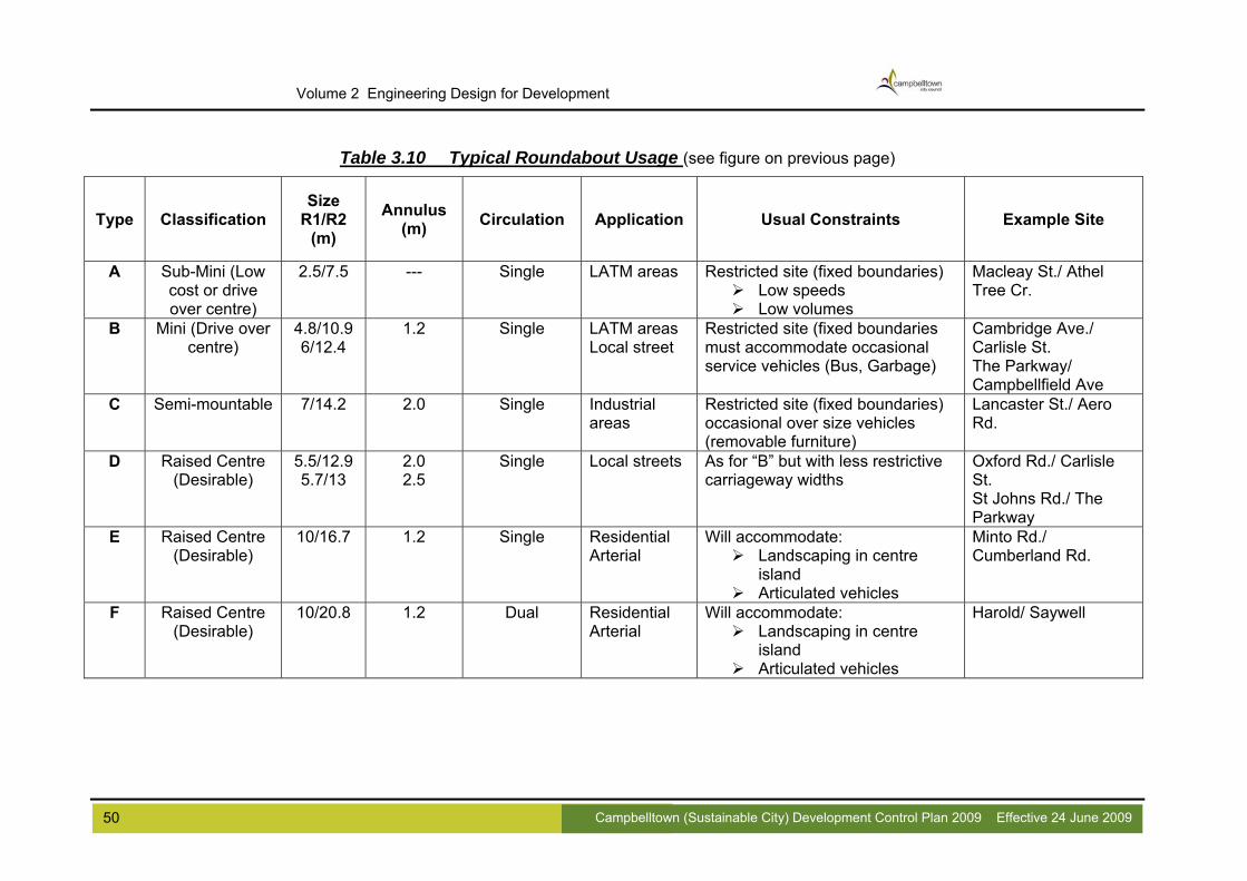
50 Campbelltown (Sustainable City) Development Control Plan 2009 Effective 24 June 2009
Volume 2 Engineering Design for Development
Table 3.10 Typical Roundabout Usage (see figure on previous page)
Type Classification Size
R1/R2 (m)
Annulus (m) Circulation Application Usual Constraints Example Site
A Sub-Mini (Low cost or drive over centre)
2.5/7.5 --- Single LATM areas Restricted site (fixed boundaries) Low speeds Low volumes
Macleay St./ Athel Tree Cr.
B Mini (Drive over centre)
4.8/10.9 6/12.4
1.2 Single LATM areas Local street
Restricted site (fixed boundaries must accommodate occasional service vehicles (Bus, Garbage)
Cambridge Ave./ Carlisle St. The Parkway/ Campbellfield Ave
C Semi-mountable 7/14.2 2.0 Single Industrial areas
Restricted site (fixed boundaries) occasional over size vehicles (removable furniture)
Lancaster St./ Aero Rd.
D Raised Centre (Desirable)
5.5/12.9 5.7/13
2.0 2.5
Single Local streets As for “B” but with less restrictive carriageway widths
Oxford Rd./ Carlisle St. St Johns Rd./ The Parkway
E Raised Centre (Desirable)
10/16.7 1.2 Single Residential Arterial
Will accommodate: Landscaping in centre
island Articulated vehicles
Minto Rd./ Cumberland Rd.
F Raised Centre (Desirable)
10/20.8 1.2 Dual Residential Arterial
Will accommodate: Landscaping in centre
island Articulated vehicles
Harold/ Saywell

4. STORMWATER DESIGN 4.1 Scope Within the broad objective of achieving in Campbelltown an optimum stormwater environment, the objectives underlying Council's stormwater design requirements are:-
Retention of the natural stormwater system where possible; A major/minor approach to stormwater design aimed at controlling flood flows so
that the severity and frequency of flooding downstream is not increased from undeveloped values;
In all designs, consideration must be given to the effect of floods greater than the design flood;
In no circumstances should the design create conditions which would be beyond the capacity of the existing downstream drainage system; and
The stormwater system comprises street gutters, pits, pipelines, overland flow paths, channels, detention basins, gross pollutant control devices and water quality improvement devices and natural watercourses.
This section of the manual sets out Council's requirements for the design of stormwater drainage for urban and rural areas. It is in no way a comprehensive design manual and it is intended to be read in conjunction with and as a supplement to the following references:
Australian Standard AS/NZ 3500.3. Plumbing and Drainage (Stormwater Drainage);
Australian Rainfall & Runoff (current edition); Australian Runoff Quality; Building Code of Australia Housing Provisions (current edition); Campbelltown City Council's Local Environmental Plan; Campbelltown (Sustainable City) Development Control Plan, Volume 1; Managing Urban Stormwater
o An Integrated Approach (currently draft) o Environmental Targets (currently draft) o Treatment Techniques (currently draft) o Urban Design (currently draft) o Harvesting and Reuse o Blue Book Volume 2 (various sections at draft or final stages) o Erosion and Sediment Control o Environmental Management of Council Operations o Other documents in the series
Water Sensitive Urban Design in the Sydney Region Resource Kit 2003; Water Sensitive Urban Design Technical Guidelines for Western Sydney 2004; Map of Salinity Potential in Western Sydney 2002; Guidelines to accompany Map of Salinity Potential in Western Sydney 2002; WSROC Western Sydney Salinity Code of Practice 2004; NSW Government Local Government Salinity Initiative Publications; Council’s Stormwater Management Plan/s; and Council’s Floodplain Risk Management Plan.
In addition, the following sources should be researched to find relevant information in relation to water quality objectives:
The relevant Government adopted or interim Water Quality Objectives (WQOs);
51 Campbelltown (Sustainable City) Development Control Plan 2009 Effective 24 June 2009

Volume 2 Engineering Design for Development
Any relevant statutory constraint (eg classified water under the Clean Water
regulation or the riparian vegetation protection measure provided by the Water Management Act, 2000);
Any environmental flow objectives endorsed by Government or being developed through any Government established forums;
The Water Quality Objectives contained in the relevant DECC approved stormwater management plan;
The requirements of any catchment or waterway focussed environmental planning instrument (SEPP/SREP); and
The Hawkesbury-Nepean Statement of Joint Intent, which provides much of the context for the sub-catchments within Menangle Park. Much of this is concerned with wastewater management but there are some relevant Water Quality Objectives that are useful to design stormwater system that would achieve these targets.
It is not intended that these design considerations will cover all situations and does not absolve the designer of the necessity to plan for specific site requirements. It is also not the intention to encompass the growing field of Water Sensitive Urban Design. The designer will need to source other documents in this regard. 4.2 Aim Current Council policy is based on riparian objective setting and riparian corridor boundary mapping, based on available information and site inspection consistent with the approach taken by DIPNR. Four key objectives are generally adopted for riparian corridors:
Provide bed and bank stability; Protect water quality; Maintain viability of riparian vegetation; and Provide continuity and connectivity.
Other matters which will generally be considered include integration with floodplain processes, management of edge effects at riparian/urban interface, and protection of natural values within channels. In many watercourses in Campbelltown the integrity of these watercourses has been significantly compromised due to many reasons (diversion, channelisation, etc). Due to the hydraulic, geomorphic, and biodiversity implications of these impacts, the NSW State Rivers and Estuaries Policy directs that such activities be halted wherever possible. In many of the developed areas of Campbelltown, development up to the flood extents does not allow formalised systems to revert to natural/naturalistic systems, however in New Release Areas key outcomes should include:
Providing a minimum 'core' riparian zone width; Providing additional vegetation width of 10m to counter edge effects with urban
interface; Bridge crossings to be provided for higher order streams; Rehabilitate/establish local provenance native vegetation; Locating services outside the core riparian zone wherever possible; Locating playing fields and other structures outside the core riparian zone; and Locating stormwater infrastructure outside the core riparian zone (and treating
before discharge).
52 Campbelltown (Sustainable City) Development Control Plan 2009 Effective 24 June 2009

The objectives underlying Council's stormwater system are the design and construction of a stormwater system that provides the following:
A high level of safety for all users; Acceptable levels of amenity and protection from the impact of flooding; Efficient conveyance of stormwater and surface runoff to provide public safety and
protect property; A controlled rate of stormwater discharge from urban land to reduce downstream
flooding impacts; Protection of the environment from adverse impacts as a result of development; Maintenance of and enhancement of regional water quality; Sustainability of infrastructure; and Economy of construction and maintenance.
To meet the above objectives, the stormwater provisions in new areas of Campbelltown should consist of a system for controlling nuisance flooding combined with an overland flow path or floodway to accommodate less frequent flood events. Major drainage designs are to aim at controlling flood flows so that the severity of flooding downstream is not increased. In all designs, consideration must also be given to the effect of floods greater than the design flood and in no circumstances should the design create conditions which would be beyond the capacity of the existing downstream drainage system. 4.3 New Release Area Proposals New release areas will generally follow the requirements set out in Section 4.1 and 4.2 above. Water quality impacts due to urban development typically include:
Introduction of greater quantities and a broader variety of pollutants to the land surface;
Increases in the quantity and frequency of runoff generation; and Increases in the erosive forces from runoff.
To counter these effects, Council will require a system which addresses each of these issues in a holistic manner. Water Sensitive Urban Design (WSUD) is the preferred method for treating new release areas. As WSUD principals are wide and varying the applicant is referred to other source material on this topic for information. Generally, WSUD requires integration of stormwater treatment into the landscape by incorporating multiple-use/open space corridors and wetlands, which maximise the management of stormwater quality, while at the same time enhancing the visual and recreational amenity of the development. Provision will need to be made to integrate these strategies into the development footprint, and land will need to be made available to locate these facilities as off-line structures to the creeks and riparian corridors. Provision of strategies to manage increased flooding on account of development, using detention facilities within each development stage, will require that areas be set aside for the construction of these facilities. The following general requirements should be considered in all new development areas:
No trapped low points will be permitted; Overland flow paths must be located on public land (roads, parks, natural
watercourses and pathways); Development sites may be designated to accommodate on site small local flows
only;
53 Campbelltown (Sustainable City) Development Control Plan 2009 Effective 24 June 2009

Volume 2 Engineering Design for Development
Formal overland flow paths must not traverse residential lots; Pathways used for overland flow conveyance must be a minimum of 15 m wide; Where overland flow currently enters a property from other upstream properties,
this flow is not to be obstructed or redirected in such a way as to increase the quantity or concentration of surface run-off;
All stormwater drainage connecting to Council’s stormwater system must do so in a manner approved and inspected by Council;
All stormwater structures are to be as visually unobtrusive as possible; and Analysis of system performance is to be undertaken using industry standard
methods and software as set out in this Guide. 4.4 Older Areas and On-site Detention (OSD) Many older areas of Campbelltown have undersized piped stormwater systems and some overland flow paths are insufficient to convey the design flows. Additionally, the current development footprint is much larger than in the past and stormwater systems cannot cope with the additional flows from impervious surfaces. In general, the applicant will be required to ensure that stormwater flows from the site are not in excess of downstream system capacity. The preferred solution is for undersized downstream stormwater systems to be upgraded to take the increased flows. Where this requirement would place an onerous amount of work on one developer, Council will consider the use of on-site detention systems. Campbelltown Local Government Area does not currently have a policy regarding the use of On-site detention. Council is currently undertaking a Flood Study which will provide a much better understanding of flooding issues than has been available in the past. Should On-site detention be found necessary as indicated above, each application will be assessed on its merit. Generally, the following design criteria apply:
The maximum discharge from the post-development site is not to exceed the pre-developed flows for all storms up to the 100-year ARI storm and concentrated flows must be managed;
Discharge from the OSD device for storms in excess of the pipe system design ARI may be via a weir, which is to be designed to have a maximum depth of flow of 150mm in a 100 year ARI storm;
The methods to determine required storage volume may be a non-time translation hydrograph method (eg. Wollongong method or Swinburne method) if the time of concentration for the total catchment is less than 30 minutes, otherwise a time translation hydrograph method (eg. Runoff Routing method) is to be used. For both cases, the capacity of the existing drainage system must be checked to ensure no increase in flows;
The OSD storage is to be located clear of any overland flow paths; Wherever possible, the runoff from the whole development site is to be directed to
the OSD storage; The minimum orifice diameter is 75 mm, protected by a screening device to minimise
blockage; Constructed tanks, carpark areas or open spaces may be used as OSD, except for
storage facilities designed for water reuse; The applicant will be required to demonstrate that appropriate safety measures have
been put in place; An overflow is to be provided for all OSD in case of storms larger than the design
event or blockage of the OSD outlet;
54 Campbelltown (Sustainable City) Development Control Plan 2009 Effective 24 June 2009

Minimum slope on storage areas are to be no less than 1% for turf areas and 0.5% paved areas;
Where the storage is to be provided in a commonly used area where ponding will cause inconvenience, the area should only flood no more than once a year, on average;
Upon completion of construction a Work as Executed Plan is to be submitted to Council prior to final certification; and
Prior to any final certification, the OSD system is to be protected by a positive covenant in favour of Campbelltown City Council.
With respect to water quality, new developments within older areas are expected to ensure that water quality objectives set in Council’s Stormwater Management Plan are achieved for that development. Conditions will be set on a site-by-site basis, taking into account any facilities which may exist within the catchment. Where no facilities exist the guidance in Section 4.3 should act as a guide. 4.5 Fill and Floor Levels Council sets fill levels of properties at the controlling 100-year flood level. Floor levels are then set at the fill level plus appropriate freeboard. Additionally, the finished floor levels for habitable areas are required to be a minimum of 150 mm above the surrounding finished ground levels (requirement of AS 2870 Cl. 5.2.2). This allowance is to accommodate minor overland flow that may affect any property in the event of an extreme storm event. Council recommends that this value be increased to 300 mm. Sites may be affected by any or all of the following:
Main stream flooding; Local creek flooding; Local overland flooding; and On-site detention flooding.
The flooding and associated freeboard which reaches the highest level on a particular site will be used to determine the required floor level. The appropriate level of freeboard shown in Table 4.1 is to be applied to the highest 100 year ARI flood level from the above list to protect development from possible impacts of system blockages, wind effects and debris. Where downstream restrictions to flow or local conditions may cause a sudden rise in floodwaters, Council reserves the right to impose a higher freeboard requirement. Where the property is large, fill and floor level requirements may be set at several critical locations of the property. These levels must be set such that linear interpolation between given levels can be carried out. Where the road is in fill or overtopping of kerbs and flow through properties may occur, a 100mm freeboard is to be provided between the ponding level of water in the road and the highest point in the footpath. Driveway construction in these instances needs to consider this requirement. Critical infrastructure including hospitals and evacuation centres may require fill and floor level controls higher than those set out in Table 4.1. Special consideration will also be given to evacuation routes and vulnerable development (like nursing homes) in areas above the 100 year ARI flood.
55 Campbelltown (Sustainable City) Development Control Plan 2009 Effective 24 June 2009
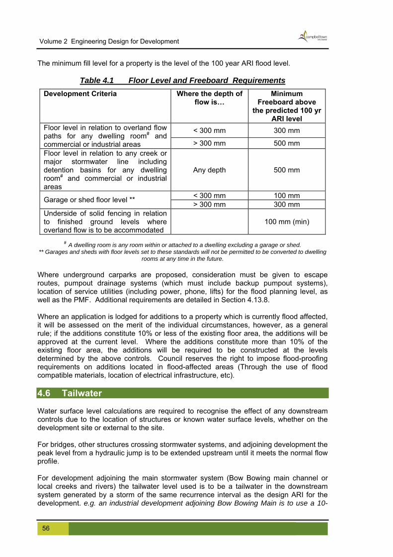
Volume 2 Engineering Design for Development
The minimum fill level for a property is the level of the 100 year ARI flood level.
Table 4.1 Floor Level and Freeboard Requirements Development Criteria Where the depth of
flow is… Minimum
Freeboard above the predicted 100 yr
ARI level
< 300 mm 300 mm Floor level in relation to overland flow paths for any dwelling room# and commercial or industrial areas > 300 mm 500 mm Floor level in relation to any creek or major stormwater line including detention basins for any dwelling room# and commercial or industrial areas
Any depth 500 mm
< 300 mm 100 mm Garage or shed floor level ** > 300 mm 300 mm Underside of solid fencing in relation to finished ground levels where overland flow is to be accommodated
100 mm (min)
# A dwelling room is any room within or attached to a dwelling excluding a garage or shed. ** Garages and sheds with floor levels set to these standards will not be permitted to be converted to dwelling
rooms at any time in the future. Where underground carparks are proposed, consideration must be given to escape routes, pumpout drainage systems (which must include backup pumpout systems), location of service utilities (including power, phone, lifts) for the flood planning level, as well as the PMF. Additional requirements are detailed in Section 4.13.8. Where an application is lodged for additions to a property which is currently flood affected, it will be assessed on the merit of the individual circumstances, however, as a general rule; if the additions constitute 10% or less of the existing floor area, the additions will be approved at the current level. Where the additions constitute more than 10% of the existing floor area, the additions will be required to be constructed at the levels determined by the above controls. Council reserves the right to impose flood-proofing requirements on additions located in flood-affected areas (Through the use of flood compatible materials, location of electrical infrastructure, etc). 4.6 Tailwater Water surface level calculations are required to recognise the effect of any downstream controls due to the location of structures or known water surface levels, whether on the development site or external to the site. For bridges, other structures crossing stormwater systems, and adjoining development the peak level from a hydraulic jump is to be extended upstream until it meets the normal flow profile. For development adjoining the main stormwater system (Bow Bowing main channel or local creeks and rivers) the tailwater level used is to be a tailwater in the downstream system generated by a storm of the same recurrence interval as the design ARI for the development. e.g. an industrial development adjoining Bow Bowing Main is to use a 10-
56 Campbelltown (Sustainable City) Development Control Plan 2009 Effective 24 June 2009

year ARI backwater control from the main channel in the design of the minor system for the site and 100 Year ARI backwater control for assessment of the major system. The following provides minimum levels to use on minor systems:
for free outfall, adopt the pipe obvert; for discharge into receiving waters, adopt a tailwater equivalent to the design ARI
flood level; for discharge into existing systems where the hydraulic grade levels are unknown,
adopt a tailwater 150mm below the natural surface/invert of gutter. for discharge into a point designed to surcharge, adopt a tailwater level equivalent to
the height of surcharge; and the tailwater level is not to be below pipe obvert.
Consideration will be given to accepting a lower starting level where this is supported by appropriate calculations demonstrating that this is suitable. 4.7 Major Minor Philosophy The "Major/Minor" concept discussed in Australian Rainfall and Runoff is adopted for urban drainage design. The "Minor" system refers to the underground piped system, designed to cater for an Average Recurrence Interval as determined in Section 4.17 of this Guide. The "Major" system refers to overland flow paths which are to be designed to convey major storm flows when the capacity of the minor system is exceeded. All drainage, whether internal or external to the site, relevant or reasonably required in respect of the proposed development is to be provided to Council's requirements at the Applicant's cost. Detailed drainage investigation and designs are to be undertaken by an experienced engineer. Applicants undertaking designs for Major stormwater systems in new release areas are advised to liaise with Council’s Manager Technical Services to ascertain Council’s specific requirements for that area. 4.8 Design Procedure Listed below is the suggested procedure for urban stormwater drainage design. The steps refer to the general order in which a drainage design proceeds. For smaller catchments some steps may be able to be omitted.
Determine Catchment area; Determine percentages impervious within the catchment to the point where design
is based; Determine design rainfall intensities; Time of concentration; Runoff coefficients; Sub-area discharge; Partial area considerations; Undertake hydrology;
Kinematic wave method; Urban Rational method; Rural rational method; Computer models;
Determine total system flows [T];
57 Campbelltown (Sustainable City) Development Control Plan 2009 Effective 24 June 2009

Volume 2 Engineering Design for Development
Determine appropriate blockage factors; Determine minor system flows [Mi] for the minimum ARI given in Table 4.5
assuming major flows will comply with safety criteria; Subtract minor system flows assuming maximum blockage from total flows to give
maximum major system flows [Ma max]; Compare [Ma max] with safety criteria; If not complying, increase the capacity of the minor system until compliance is
achieved [Mi comp]; Design minor and major system for the appropriate flows; Size minor system for no blockage and major flows for blockage in the minor
system; Design pit inlets; Design pipelines, culverts etc; Design On-site detention measures if required; Determine water quality criteria; Assess safety of system; Design water sensitive elements to appropriate criteria;
4.9 Hydrology Detailed designs for water quantity are to provide flood levels for the site for the 100 year ARI and PMF events, for inclusion on S149 certificates where flooding is due to river, mainstream, tributary creek or local catchment effects. The applicant must show that the development has been raised to levels sufficient to comply with Council’s requirements.
4.9.1 Rainfall IFD Because of the size of the city of Campbelltown, rainfall patterns are not uniform across the LGA due to local topographic effects. The City has been broken down into 3 districts for rainfall and the appropriate area must be used in calculations. Design rainfall Intensity Frequency Duration (IFD) relationships are given in Appendix B for each of the districts, Glenfield, Campbelltown and Wedderburn. These names do not necessarily refer to the suburbs of the same name in this instance. The applicant should refer to the map in Appendix B. 4.9.2 Temporal Patterns Appropriate temporal patterns from Australian Rainfall and Runoff are provided in Appendix B for ARI’s less than 30 years and greater than 30 years. These are the same as those found in AR&R for the Campbelltown region. 4.9.3 Contributing Catchment The catchment area at any point is defined as the limits from where surface runoff will make its way, either by natural or man made paths, to that point. Consideration is to be given to likely changes to individual catchment areas due to the full development of the catchment. Catchment area land use is to be based on current available zoning information or proposed future zonings, where applicable. Where no detailed survey of the catchment is available the following sources may provide adequate information for design:
1:4000 orthophoto maps; information may be requested from Council and where information is
available it will be provided (a fee is charged for advice given for properties
58 Campbelltown (Sustainable City) Development Control Plan 2009 Effective 24 June 2009

zoned industrial and commercial). Council will only provide contour information. The applicant must determine the catchment contributing; and
undertake survey. The level of detail required will dictate the suitability of each of these methods. Consideration must be given to full development in the upstream catchment to the limit of the current zoning. 4.9.4 Impervious Percentages Table 4.2 is to be used to determine the appropriate values of percentage impervious for each of the following types of development. It must be understood that Council will only accept the percentage impervious that exists at the time of development as the absolute minimum. Variation of the values in Table 4.2 must assume that homeowners will include other impervious surfaces after completion of initial development. These may include sheds, pergolas, swimming pools and path paving. The values in Table 4.2 are to be used in urban rational method calculations and in computer models. A tabulation of the coefficients of runoff for use in the Urban Rational Method are included in Appendix B and assume the highest percentage impervious in the range. Use of values lower than the maximum will need to be justified and use of values lower than the range given are unlikely to be supported.
TABLE 4.2 Percentage Impervious for Various LandusesLanduse Lot Size Percentage
impervious * #Natural state 0% Rural 5%
>2000m2Residential 30% 1000 – 2000 m2Residential 60% 600 – 1000 m2Residential 70% 400 – 600 m2Residential 80%
<400 m2Residential 90% Open Space 10% minimum Industrial 90% Commercial 100%
* Values other than the nominated values will be considered only if substantiated # Council reserves the right to impose higher values if warranted
4.9.5 Pit Capacity Determination of overland flow rates should also account for pipe blockage factor as per Table 4.3. These factors apply in all storm events. Additional information is found in Section 4.12.6.
Table 4.3 Pit Blockage Factors PIT TYPE % BLOCKAGE % CAPACITY
Sag 50% 50% Grade 20% 80%
In design of the minor system sufficient pits must be provided, with acceptable blockage factors used in the calculations, to ensure that the pipes run fully charged to the design limit of the system in the design storm event.
59 Campbelltown (Sustainable City) Development Control Plan 2009 Effective 24 June 2009

Volume 2 Engineering Design for Development
For design of the major system, it must be assumed that the maximum blockage, in accordance with Table 4.3 occurs.
4.10 Hydrologic Methods The following hydrologic methods will be considered acceptable to Council in the following situations:
Rural catchments Urban Catchments Unit hydrograph methods Urban Rational method Rural Rational method Kinematic Wave Computer models Computer models
Where catchments have mixed uses and neither a fully rural or fully urban model is appropriate, the preference is for a computer based routing model, which can accurately model all landuses. These methods and acceptable parameters for their use are discussed in the following sections.
4.10.1 Rural Unit hydrograph methods Unit hydrograph methods suitable for fully rural catchments are set out in the current edition of Australian Rainfall and Runoff. The method is applicable to a large range of catchment sizes, but it is usually not applicable to very catchments, to very small catchments, nor to urban catchments. Use of the Rural Rational Method as described in Section 4.10.2 is the preferred approach. 4.10.2 Rural Rational method The Rational Method will be acceptable for all sized rural catchments.
QY = 0.278 x CY x Itc. y x A peak flow rate (m3/s) of average recurrence interval Y years
Where: QY =
CY = runoff coefficient (dimensionless) for ARI of Y years Itc. y = average rainfall intensity (mm/hr) for design
duration of tc hours and ARI of Y years found in the tables in Appendix B area of catchment (km2) A =
The Probabilistic Rational Method discussed in AR&R is to be used to determine the time of concentration, tc for rural catchments.
0.76A0.38 tc = area of catchment (km2) Where: A =
Further information can be found in Book 5 of AR&R.
60 Campbelltown (Sustainable City) Development Control Plan 2009 Effective 24 June 2009
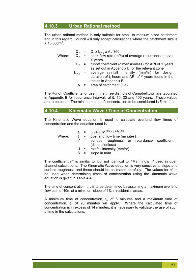
4.10.3 Urban Rational method The urban rational method is only suitable for small to medium sized catchment and in this regard Council will only accept calculations where the catchment size is < 15,000m2.
QY = CY x Itc. y x A / 360 peak flow rate (m3/s) of average recurrence interval Y years
Where: QY =
CY = runoff coefficient (dimensionless) for ARI of Y years as set out in Appendix B for the relevant zone
Itc. y = average rainfall intensity (mm/hr) for design duration of tc hours and ARI of Y years found in the tables in Appendix B
A = area of catchment (Ha) The Runoff Coefficients for use in the three districts of Campbelltown are tabulated in Appendix B for recurrence intervals of 5, 10, 20 and 100 years. These values are to be used. The minimum time of concentration to be considered is 5 minutes. 4.10.4 Kinematic Wave / Time of Concentration The Kinematic Wave equation is used to calculate overland flow times of concentration and the equation used is:
6.94(L n*)0.6 / I 0.4S 0.3 tc = Where: tc = overland flow time (minutes)
n* = surface roughness or retardance coefficient (dimensionless)
I = rainfall intensity (mm/hr) S = slope in m/m
The coefficient n* is similar to, but not identical to, “Manning’s n” used in open channel calculations. The Kinematic Wave equation is very sensitive to slope and surface roughness and these should be estimated carefully. The values for n* to be used when determining times of concentration using the kinematic wave equation is given in Table 4.4. The time of concentration, tc , is to be determined by assuming a maximum overland flow path of 40m at a minimum slope of 1% in residential areas. A minimum time of concentration, tc, of 6 minutes and a maximum time of concentration, tc, of 20 minutes will apply. Where the calculated time of concentration is in excess of 14 minutes, it is necessary to validate the use of such a time in the calculations.
61 Campbelltown (Sustainable City) Development Control Plan 2009 Effective 24 June 2009

Volume 2 Engineering Design for Development
Table 4.4 n* Values for Use with Kinematic Wave Equation
Roughness Coefficient n* @#Surface Type Concrete or asphalt 0.015 Bare sand 0.016 Gravelled surface 0.03 Bare clay - loam soil (eroded) 0.033 Sparse vegetation 0.13 Short grass prairie 0.20 Lawns 0.48 Road/paved areas 0.01 Residential 0.08 Medium density residential 0.06 Industrial/commercial 0.04 Parkland 0.15 Open space (natural bushland) 0.3
@ Values other than the nominated values will be considered only if substantiated # Council reserves the right to vary these values if warranted
Modified from AR&R, 1987 and Penrith City Council Guidelines for Engineering Works for Subdivisions and Developments, 1997
4.10.5 Partial Area Flows In urban catchments, it is possible that a greater flow rate may be obtained by applying the Rational Method to the lower part of the catchment with a time of concentration less than the full area travel time. These partial area effects commonly occur when large paved areas are directly connected to the pipe inlet, and the sub-catchment discharge is based on a larger pervious area. Similarly, partial area effects can also occur, where a large open space catchment contributes to an urban catchment, with a time of concentration substantially different to the urban catchment. In areas where there is a possibility that partial area effects may occur, a partial area check, based on times of concentration of impervious areas directly connected to the pipe system, is necessary. The following situations are known to increase the risk of partial area effects:
When sub-catchments are not homogeneous in terms of landuse; When variations of slope or landuse occur within a catchment; and Catchment shape can sometimes be a cause.
4.11 Computer Models Where catchments are large and reasonably accurate levels of flow rate prediction is necessary, peak flow rates should be determined using a recognised runoff routing computer model. Council's preferred models are RAFTS-XP or DRAINS. Computer models are ideally placed to model catchments with mixed land uses due to the ability to apply separate parameters to each parcel of land. When using hydrologic models the following will apply:
Parameters used in hydrological models must be in accordance with the values acceptable to Council as outlined in Appendix B of this Guide and consistent with values recommended in AR&R;
62 Campbelltown (Sustainable City) Development Control Plan 2009 Effective 24 June 2009

Documentary evidence of the parameters used must be supplied with any submission to Council; and
Where computer programs are used, electronic copies of the final data files are to be provided on submission of the design to Council. Details on the use of specific programs and additional requirements when using these are given in Appendix B. Where values other than those recommended are used, their use must be justified.
The use of industry standard computer models by Professional Engineers for stormwater design is supported by Council. Should Consultants wish to use a program not mentioned here, details are to be submitted to Council prior to use. In this regard Council’s preferred models are: Hydrology - RAFTS-XP DRAINS TUFLOW Hydraulics - HEC-RAS TUFLOW Water quality - MUSIC Where computer models other than these are used, full details of the model set-up and detailed output files and interpretation will be required in the form of a written report. Where computer models are used, the latest version of the program must be used. A hydrological report is to be submitted stating all the parameters used to calculate the flows. A hardcopy is to be submitted to Council. Electronic copies of final input and output computer files together with accompanying catchment and layout plans, for hydrological, hydraulic and water quality models must be provided for Council's records at the time of lodging detailed engineering plans. 4.12 Minor System The minor stormwater system is to be designed to accommodate the nominal flows identified in Table 4.5 below. The system may be required to accommodate higher flows if the major system cannot safely carry the difference between the 100 year ARI flows and the capacity of the minor system.
Table 4.5 Nominal Design ARI for the Minor System
{PRIVATE }LAND USE A.R.I. (years) Rural Residential 5 Urban Residential 5 Neighbourhood shopping centres 10 Industrial areas 10 Service trades areas 10 Low lying and flat residential areas 10 Town centres (Macarthur, Campbelltown & Ingleburn) 20 Major Shopping Centres 20 Major road crossings 20 Arterial Road crossings 100 Access to emergency facilities 100 Trunk stormwater facilities located in open space and drainage reserves ##
¼ to 5
## the return period adopted will depend on adjoining land use, scour potential, public nuisance, safety and environmental considerations
63 Campbelltown (Sustainable City) Development Control Plan 2009 Effective 24 June 2009
Volume 2 Engineering Design for Development
An additional requirement is that sufficient inlet capacity, allowing for blockages, must be provided to ensure that these systems are fully charged in the design event. In larger developments all pits are required to be embossed with stamping indicating “ Drains to Name of appropriate waterway”. Where the appropriate waterway is either the Georges River or the Nepean River as applies. Low flow provision only is required for Council’s formalised stormwater system. Where these systems are natural or naturalistic environmental flows are to be allowed to run within the system. Minor flow in Roadways The following criteria are to be met for minor system flows collected from the roadway:
Bypass from any gully pit on grade is not to exceed 15% of the total flow at the pit (Full Capture Desirable);
Gutter flows must not overtop the kerb; The minimum lintel size for gully pits on grade is 1.8 metres clear opening; Sag pits are to be designed based on a maximum depth of ponding up to the top
of the kerb. A minimum blockage factor of 0.5 must be used to calculate ponding depth;
The minimum lintel size for sag pits is 2.4 metres clear opening; Where flows in the gutter exceed 20 l/s or 1m in width at an intersection it will be
necessary to intercept these flows with additional upstream kerb inlet pits; The location of gully pits on curves is to be avoided. Any such kerb inlet pits are to
be located clear of any pedestrian desire lines; Maximum spacing between directly connected pits is not to exceed 80m; Additional inlet pits may be required at the discretion of the Council’s Development
Engineer if blocking of a single pit could cause serious flooding; The location of gully pits in accessways and vehicular entrances must be avoided; Inlet pits are to be provided at the upstream tangent point of curves in the gutter
line, the radius of which is less than 30 metres; Standard pits are to be provided in drainage lines at all changes in grade, level or
direction and at all pipe junctions, except as allowed for in curved pipeline designs; The minimum clearance from the top of the grate to the design water surface level
in the pit is to be 150mm; and Pipe grading across pits are to be designed on the following basis:
No change in direction or diameter - minimum fall 30mm; No change in diameter but direction change - minimum fall 50mm; and Changes in diameter are to be graded obvert to obvert.
Most existing grates within the city area are Durham (DMR A190) type grates with bars parallel to the kerb. In some circumstances these pit configurations have less capacity than the welded steel ("Weldlok") type grates. Any analysis of existing drainage systems must therefore account for inlet capacities appropriate to the type of grate/inlet configuration. Any new grates are to be “cycle-friendly” galvanised lock down grates. Once the sub-catchment flows are known, pit inlets can be designed in accordance with the charts contained on the following pages. All new pit inlets must be constructed using cycle friendly galvanised lock down grates with appropriate skirts. On grade, percentage capture by grates is mainly dependent on lintel size, tests show that the two types of grates mentioned above have similar performance characteristics on grade when in combination with a lintel. The charts for the sag inlets are based on tests conducted by the RTA N.S.W., Water Research Laboratory and the West Australian Institute of Technology and incorporate blockage factors given in Table 4.3.
64 Campbelltown (Sustainable City) Development Control Plan 2009 Effective 24 June 2009

Alternatively inlet capacities can be calculated from first principles using formulas as detailed in Section 1.5.4(iii), Book 8 (page 15) of AR&R. If using these formulae, the blocking factors in Table 4.3, are to be applied. Where it is proposed to use a grate not conforming to these requirements, it is necessary to submit a detailed investigation from an accredited laboratory establishing the performance of the grate prior to it being accepted or rejected by Council. Hand calculations for the design of pit inlets are to be tabulated on "Hydrological Design Sheet 1" (column 16 to 20) in Table 4.6 (at end of chapter). Computer analyses are to conform to the inlet capacities graphed on Figs. 4.2 to 4.8 (at end of chapter), unless prior approval has been received from Council's Development Engineer. Sag pits are to be designed based on a depth of ponding, up to the top of the kerb. Ponding depths can be calculated using design charts, Figures 4.5 to 4.8 (at end of chapter) of this Guide. Lintel sizes must be commensurate with inflow requirements. A nominal internal lintel size of 1.2m is placed on junction pits. The minimum nominal internal lintel size for grated gully pits in public roads is 1.8m, unless the pit's main function is to facilitate a change in direction or grade of the stormwater pipe, in which case the nominal internal lintel size may be reduced to 1.2m. The minimum nominal internal lintel size for grated gully pits in "sags" is 2.4m. Kerb Inlet Pits Kerb inlet pits for pipes up to 1050mm diameter are to be constructed in accordance with SD-S06. Where pipes sizes exceed 1050mm structural details are to be provided. Angle Pits and Junction Pits Angle and junction pits are to be constructed in accordance with SD-S10, SD-S11 and SD-S12. Surface Inlet Pits Where surface inlet pits or surcharge pits are required, they are to be constructed in accordance with SD-S08 and SD-S11. Special Pits Circumstances may require the inclusion in the design of a special inlet pit or a standard structure commonly used by the Road and Traffic Authority. Council’s Development Engineer is to be consulted as to their use in a particular circumstance and of the inlet capacities to be used in each instance. A detail of any non Council Standard pits is to be included on engineering plans. Precast Pits Precast pits are not to be used on public roads. Approved heavy-duty reinforced concrete precast pits may be used in trafficable areas inside private property. Plastic and Fibre reinforced concrete pits are only to be used in non-trafficable areas. The contractor is to strictly follow the manufacturer's construction recommendation and the pits are to be inspected by Council’s Development Engineer prior to placement and prior to backfilling.
4.12.1 Preliminary Layout of Proposed Stormwater An assessment of the topography will determine the location of proposed drainage paths. Once the location of a proposed network is defined, trial pit locations should be assessed. Generally, pits should be spaced with minimal bypass flows.
65 Campbelltown (Sustainable City) Development Control Plan 2009 Effective 24 June 2009

Volume 2 Engineering Design for Development
An example procedure for locating pits is detailed in "Technical Note 2" in Book 8 of AR&R. Catchment areas to each pit are to be determined from contour information and proposed property boundaries. A site inspection is to be made to check the contour information and assess the likelihood of any flow path deviations which may occur as a consequence of existing or proposed developments. Changes to flow paths can occur as a result of the construction of fences, retaining walls, buildings etc. after the construction phase of the subdivision. The impact of these changes is to be considered at the design stage. Sub-area discharges can be calculated using the procedures detailed below. Major system flow paths should be defined at this stage, and analysed according to the procedures detailed in Section 4.16. Discharge for each sub catchment may be calculated using the Rational Method formula as detailed in Section 4.14. "Hydrological Design Sheet 1" (From AR&R), copy in Table 4.6 (at end of chapter), sets out the preferred format for these calculations. Technical Note 6 (page 24) of Book 8 of AR&R details a worked example for these calculations. "Hydrological Design Sheet 2" (from AR&R), copy in Table 4.7 (at end of chapter), can then be used to calculate the flows along each reach of the pipe system. Where calculations are proposed to be presented as a computer hardcopy, it is necessary to obtain approval from Council's Development Engineer prior to doing so. Hand calculations are to be submitted in the format shown on Hydrological Design Sheets 1 and 2. 4.12.2 Hydraulic Grade Line Analysis Hydraulic grade line (HGL) analysis is required for the piped stormwater drainage in the following instances:
All large inter-allotment drainage lines; Low level property drainage connecting into a Council pit or street pipe; In situations where determination of hydraulic control is critical; Where pipe discharge exceeds 100L/s or as directed by Council
Development Engineers; and All street drainage systems.
In cases where determination of the HGL is critical to the successful implementation of a design, such an analysis will be required to be submitted with the development application. Pit Losses Pit losses are to be calculated based on the following:
The pit pressure change coefficient (Ku) for each pit is to be determined using the tables from the Missouri Charts or Hare Charts;
The water level in a pit may be assumed to be coincident with the highest HGL level in the pit;
When the water level (i.e. HGL) calculated is below the obvert level of the upstream pipe, the obvert level of the upstream pipe is to be adopted as the water level for calculation of upstream pipe HGL;
66 Campbelltown (Sustainable City) Development Control Plan 2009 Effective 24 June 2009

Where a drop pit is located at the top of a drainage branch or where the obvert of the outlet pipe is 1/4 of its diameter or greater below the invert of the upstream pipe then the Ku is to be no less than 4.5;
Intermediate cases may be determined by linear interpolation of Ku up to 4.5. Because of the high losses in these pits, it may be preferable to design a steeper section of pipe; and
For drop pits with more than 600mm drop, the length of the pit is to be designed to avoid direct discharge onto the facing wall which may induce scouring.
In general friction losses in pipes are to be determined using the Colebrook White equation. In most cases the design coefficients of roughness are to be in accordance with the values in Table 4.8.
Table 4.8 Pipe Friction for Pipes
{PRIVATE }Pipe Material
Manning’s "n" Colebrook-White "k", (mm)
Concrete 0.013 0.6 UPVC 0.009 0.03 FRC 0.013 0.6
Design chart for k = 0.6mm (concrete) is included as Figure 4.1 (at end of chapter). Shock losses at pits, slope junctions, bends, transition structures, inlets and outlets are to be considered. Reasonable ku values are to be selected using "Missouri charts", Hare equations, US Corp of Engineers mitre bend charts or other recognised procedures. 4.12.3 Pipeline Design Stormwater pipeline designs are to include consideration of:
Friction loses; Pit losses; and Bend losses.
Drainage pipe systems are to be designed as an overall system incorporating pipe and all other losses, with due regard to the upstream and downstream system and not as individual pipe lengths. Drainage pipeline systems are to be designed as gravity systems flowing full at design discharge, and may be pressurised with the use of appropriate pits and joints only with Council approval. Hydraulic grade/energy line calculations will be required for all major pipelines, and these are to be shown on long sections. Consideration must be given to the head available in order to determine whether the system can achieve the capacity required. When pipelines are used to cater for 100-year ARI flows, the minimum freeboard in a pit is to be 150mm. Bends may be permissible in certain circumstances and discussions with Council regarding their use is required prior to detailed design.
67 Campbelltown (Sustainable City) Development Control Plan 2009 Effective 24 June 2009

Volume 2 Engineering Design for Development
4.12.4 General Requirements for Pipelines Generally pipes are to be constructed in straight lines between pits. Where possible, in order to reduce head losses, large changes of direction are to be avoided. The minimum grade in pipelines is to be 1%. The minimum pipe size within roadways or Council lands is 375mm diameter. Curved pipelines where permitted are to be installed strictly in accordance with the manufacturer’s recommended radii and specification. Complex or unusual situations should be discussed with Council’s Development Engineer prior to the finalisation of design. Pipelines are to cross roads at right angles to the road centreline. Where this is not practical or possible the pipelines are not to be placed at an angle less than 60% to the centreline. For any pipe system, a downstream pipe of smaller diameter than the upstream pipe will not be permitted. The exception to this is trunk drainage systems where surcharge has been allowed for. Pipelines are to be designed for a minimum velocity of 0.6m/s for 1 in 1 year flow for self cleansing and a maximum velocity of 6.0m/s for the design ARI for scour protection. The pipeline is to be designed so that the depth of the gully pits are sufficient to induce the designed velocity. Gully pits, junction pits and change of direction pits are to be so designed to minimise pressure head losses. The inlet and outlet drains to pipelines are to be designed so as to avoid scouring or silting velocities during storm flows, and adequate scour protection satisfactory to Council’s Development Engineer is to be provided at the outlet of all stormwater lines. The maximum HGL Level is to be 150mm below the gutter invert level at each pit. Where pipe grades are in excess of 15%, concrete thrust blocks are to be placed at every third collar. Non-standard drainage structures for pipes larger than 750mm diameter are to be designed and certified by a Registered Structural Engineer by way of an accompanying letter or by statement on the engineering plans. Drainage lines in road reserves are to generally be located under and parallel to the kerb (for detailed alignment requirements see Council SD-S06). Drainage lines in easements are to generally be centrally located within the easement. Reinforced Concrete PipesUnless a higher class or type is specified, the pipes are to be precast reinforced concrete - Class "3", and are to be of the spigot and socket rubber ring joint type. Installation and backfilling are to comply with Australian Standards and/or respective manufacturer’s requirements. The minimum backfilling specification is to be HS as defined in AS 3725, unless noted otherwise.
68 Campbelltown (Sustainable City) Development Control Plan 2009 Effective 24 June 2009

Fibre Cement Pipes Unless a particular class or type is specified, the pipes are to be Fibre Cement Stormwater Drain pipe - Class 35 and must be of collared rubber ring type joint type. As fibre cement pipelines do not allow deflections at the joint, the use of fibre cement pipes for curved pipelines are subject to the submission of an alternative design. The design is to indicate the deflection angle and the location of fabricated bends. Installation and backfilling are to comply with Australian Standards and/or respective manufacturer’s requirements. The minimum backfilling specification is to be HS as defined in AS 3725, unless noted otherwise. Vitrified Clay Pipes All pipes are to be of first quality spigot and socket with rubber ring jointed vitrified clay. Installation and backfilling are to comply with Australian Standards and/or respective manufacturer’s requirements. UPVC Pipes In trafficable areas on private property, the use of UPVC pipe Class SH, up to and including 300mm diameter, is permitted. UPVC pipes are to be backfilled with approved compacted granular material (eg washed river sand) for the trench depth in trafficable areas and 150mm above the pipe in other areas. Installation and backfilling are to comply with Australian Standards and/or respective manufacturer’s requirements. Minimum Depth Stormwater pipelines are to be deep enough so as not to prejudice the opportunities to drain any undeveloped upstream land. Minimum cover over the pipeline is to be in accordance with the relevant Australian Standards and in accordance with the manufacturers specifications. Pipe Class Pipe class is to be selected to provide adequate strength to meet overburden and traffic loads. Pipe loadings are to be determined in accordance with the relevant Australian Standards for the pipe type in question. In assessing pipe loadings, consideration is to be given to bedding type, trench widths, loading conditions including live loads and construction loads. Where load limits apply, the location and load limitation is to be clearly shown on the submitted plans. 4.12.5 Pit Design Determination of overland flow rates should also account for pipe blockage factor as per Table 4.3. These factors apply in all storm events. Pit Pressure Loss Coefficients The applicant is required to consider the impact of losses due to the following:
Bend losses; Service entry losses; and Contraction/ expansion losses.
69 Campbelltown (Sustainable City) Development Control Plan 2009 Effective 24 June 2009
Volume 2 Engineering Design for Development
Where the obvert of the outlet pipe is 1/4 of its diameter or greater below the invert of the upstream pipe then the Ku is to be calculated by considering upstream inflow as grate flow, i.e. as a top of the line pit. Drop pits with more than 600mm drop over the length of the pit are to be designed to avoid direct fall onto the wall which will induce scouring of the pit wall. Pit Pressure Loss Coefficients are to be calculated for each pit using Hare’s equations or Missouri Charts. A number of head loss coefficients have been included for information in Figures 4.2 and 4.3 (at end of chapter). These figures cover only the most common situations and other combinations will require the designer to seek additional information. Computer programs with default pressure change coefficients are not acceptable unless they are consistent with those from the charts in this Guide. The chart used and relevant coefficients for determining the value from that chart are to be noted on the hydraulic summary sheet provided for plan checking and included on the final design drawings. Pit Loss factors for drop pits are to be calculated in accordance with the charts previously mentioned. An allowance is to be made relative to the drop through the pit. When the obvert of the outlet pipe is at or greater than Do/4, below the invert of the upstream pipe, the inflow is to be regarded as grate flow. That is, when the obvert of the outlet pipe is 1/4 of its diameter or greater, below the invert of the upstream pipe then the pipe loss factor (k) is to be no less than 4.5. Intermediate cases may be determined by linear interpolation of pit loss factor (k) up to 4.5. Because of the high losses in these pits, it may be preferable to design a mitre bend or a steeper section of pipe. Benching in Pits The base of the pit is to be formed to provide a constant fall to the outlet of the pit to stop the ponding of water. A minimum fall of 1% is required. Where inlet and outlet pipes are offset or any situation arises which could be considered hydraulically inefficient, benching is to be used to streamline flows in the pit. Benching must not restrict the hydraulic efficiency of the pit in any way. The top pit in the system must have sufficient depth to generate sufficient head to charge the pipe. This can be calculated by using coefficients derived from the Missouri Charts. The k value of 4.5 should not automatically be assigned to all starter pits but each pit is to be assessed on its merits. Sufficient pits must be provided, with acceptable blockage factors used in the calculations, to ensure that the pipes run fully charged to the design limit of the system in the design storm event. Drainage is not to be carried a greater distance than 80 metres in pipelines without adequate inspection manholes. Where the pipeline diameter exceeds 1200mm, this distance may be increased to 100 metres. Drainage pits are to be designed wherever possible such that the inlet and outlet walls are perpendicular to the centreline of inlet and outlet pipes.
70 Campbelltown (Sustainable City) Development Control Plan 2009 Effective 24 June 2009

Wherever possible, drainage pits are to be designed so that the pipe centrelines intersect on the downstream pit face. All drainage structures deeper than 1.5m must include appropriate reinforcing to Engineer's (structural) requirements. Pits deeper than 2.0m are to be structurally designed and certified. The charts given in Figures 4.4 to 4.8 (at end of chapter) are to be used to determine pit capacities. Unless otherwise stated these pit charts do not include any blockage factors. The percentage of theoretical capacity allowed in relation to type of pit is given in Table 4.3. Where surface inlet pits are located in channels they are to be designed at a maximum spacing of 80m. A raised grate is to be used in all cases unless otherwise approved by Council’s Development Engineer. Generally the pits are located below the 1 in 100 year flow level of the channel preferably at the invert of channel. All pits are to be designed to minimise Occupational Health and Safety impacts with special consideration given to the Confined Spaces Legislation. 4.12.6 Culvert Design Culverts are to be designed in accordance with culvert hydraulic theory, i.e. the culvert capacity is determined by the flow conditions, depending on whether inlet control or outlet control governs. Recommended design procedures are contained in Section 3 Hydraulics of Precast Concrete Conduits - Hydraulic Design Manual - by the Cement and Concrete Pipe Association. Where pipe or box culverts are used to convey discharge under a road or other embankment both inlet and outlet control are to be considered with the situation that generates the lower flow being assumed to govern in the design. Both inlet and outlet control are highly dependent on the entry losses assumed. Table 4.9 shows the Entry Loss Coefficients, ke , to be used. Where the culvert is a road crossing, the culvert is to be designed to safely convey stormwater. The channel upstream is to incorporate an appropriate allowance for afflux through the culvert. Scour protection is to be included at the outlet of all culverts as required to ensure integrity of the downstream conveyance. Culvert inlets must be designed using 50% blockage factor for the 1 in 100 year Average Recurrence Interval flow. i.e. all inlets are to have grates of the opening surface area not less than twice the downstream pipe cross-section area. Base slabs for box culverts are to be cast-in-situ and designed by a certified practicing structural engineer. State Government agencies DIPNR and NSW Fisheries may have requirements for fauna movement. General guidance can be found in “Fish Passage Requirements for Waterway Crossings”, NSW Fisheries, Jan 2003. A suggested tabulation of the design calculations is contained in Table 4.13.
71 Campbelltown (Sustainable City) Development Control Plan 2009 Effective 24 June 2009

Volume 2 Engineering Design for Development
Table 4.9 Entrance Loss Coefficient, ke
Design of Entrance KePIPE CULVERTS
Square cut 0.5 Pipe projecting from fill Socket end 0.2 Square end 0.5 Headwall with or without wingwalls Socket end 0.2
Pipe mitred to conform to fill slope Precast end 0.5 Field cut end 0.7 BOX CULVERTS
Headwall parallel to embankment square edge on three edges
0.5 No wing walls
Three edges rounded to 1/12 barrel dimensions
0.2
Square edge at crown 0.4 Wing walls at 30o to 75o to barrel Crown rounded to 1/12 culvert height 0.2
Wing walls at 10o to 30o to barrel Square edge at crown 0.5 Wing walls parallel (extension of sides) Square edge at crown 0.7
Source Hydraulics of Precast Concrete Conduits, Concrete Pipe Association of Australia, 1986
There are a number of computer programs available for the design of culverts. Council's Development Engineer should be consulted regarding the suitability of individual programmes
4.13 Major System The major system must convey all flows that cannot be carried by the minor system up to the designated flood, the 100 yr ARI flood, with allowances for freeboard as set out in Table 4.1. Flows in excess of the 100 yr ARI event must be considered in terms of safety and impacts, but are not required to be fully contained within the major system. Floodways to cater for the storm flows up to the 100 year ARI are to be provided along or as near as possible to the alignment of existing water courses and drainage depressions. These floodways are to be properly designed and accurately constructed to the levels and grades of the design. Adjoining low-lying land is to be filled to appropriate levels to ensure containment of flood flows and proper surface drainage. Where possible open spaces should be provided over the floodway such that the provision is useful and useable and capable of easy maintenance. Other land uses for floodways can be considered but they must be fully compatible with its primary role. Flood warning signs are required in all locations where floodwaters may pond or flow and special consideration will need to be given to car parks used as floodways, detention basins and channels. The design analysis carried out is to take into account the possibility of special damage or danger to life and property which might occur in specific situations. The frequency of flooding recommended or adopted for design in such cases is to be the subject of specific advice and reports to Council for determination. In no circumstances is the design flood to be less than the 100-year ARI. Council requirements are aimed at ensuring that all properties are protected against the 100 year ARI flood. Properties are to be free from inundation from floods of up to 100-year
72 Campbelltown (Sustainable City) Development Control Plan 2009 Effective 24 June 2009

average ARI recurrence interval. No buildings or other structures are permitted within areas inundated by such flows.
4.13.1 PMF Requirements The Probable Maximum Flood (PMF) is defined as the peak flood derived from routing the Probable Maximum Precipitation (PMP) through the stormwater system. Safe passage of the PMF must be demonstrated on major systems. Where there is risk to property and/or life it will be necessary to check the results for the Probable Maximum Flood (PMF). Where the PMF results in catastrophic failure or considerable damage then the design criteria is to take account of the risk and implement measures to eliminate or limit that risk. Such additional investigation is required in the following situations:
Design of dam spillways; Design of detention basins; Adequacy of existing dam spillways; Major bridge design; Major release areas; and Major public infrastructure such as hospitals.
All developments must consider the impact of storms greater than the 100 year ARI event in terms of evacuation routes. No properties should be isolated or become islands in events greater than the 100 year ARI event. Flooding risks should increase incrementally, i.e. no small increase in runoff should generate major increases in affectation. The methods set out in “The Estimation of Probable Maximum Precipitation in Australia: Generalised Short-Duration Method” published by the Commonwealth Bureau of Meteorology (June 2003, as amended) are to be used in the estimation of the PMP.
http://www.bom.gov.au/hydro/has/gsdm_document.shtml
4.13.2. Floodways and Channels Campbelltown has an extensive existing system of floodways and formalised channels. Where opportunities exist for these systems to be converted to naturalistic systems, such opportunities will be taken. Any areas where such modifications may be possible will be identified following completion of Campbelltown’s Floodplain Risk Management Plan. Any development adjoining natural creeks, which form part of the major stormwater system, is to be provided with environmentally sensitive connections to such systems. The use of natural waterway corridors must be maximised and where opportunities exist to return formalised systems to a more natural state, these opportunities must be taken. The straightening, widening, lining or piping of natural watercourses is not permitted. In this regard, prior to design, the applicant should, where appropriate,
73 Campbelltown (Sustainable City) Development Control Plan 2009 Effective 24 June 2009

Volume 2 Engineering Design for Development
liaise with the Department of Water and Energy (DWE) regarding the exact classification of a watercourse. Controls on the width of riparian corridors and the procedures for managing riparian land will vary depending on specific issues that apply to the site. The required width will vary from a buffer strip of 5-20 m to a wider corridor of up to 100m in pristine areas. Integrated Development should be referred to the appropriate State Government Agencies including DECC and DWE. Floodways and connections to existing floodways are to be properly designed and accurately constructed to the levels and grades of the design. Where the upstream minor system has a higher capacity than the low flow capacity in the floodway, adequate provision for surcharge flows must be made. This will include consideration of bed and bank stability in the receiving waters. Design of such systems must take into account the requirements in Section 4.6 regarding tailwater. Floodways may be provided as dedicated stormwater elements, within open space and through car parks in commercial and industrial development. Multiple use of stormwater areas is supported where such other uses are compatible with the primary role of conveyance of stormwater flows. Where safety, amenity and maintenance considerations cannot be incorporated to allow multiple use, the area is to be dedicated as drainage reserve. Other land uses for floodways will be considered but they must be fully compatible with its primary role. The velocity x depth product (VD) for floodways is not restricted, however all attempts are to be made to minimise VD to minimise environmental impacts and maximise safety subject to maintaining flows within the defined floodway. Major floodways along Bow Bowing Bunbury Curran Creek generally consist of a "low flow" system (piped or lined) together with a grassed waterway. Some sections comprise fully concrete lined channel. Connections to this system are to be in accordance with SD-S05. Consideration will be given to alternative designs which can demonstrate:
performance goals have been achieved; reduced environmental impacts; and reduced maintenance requirements and costs.
Afflux should be avoided at all structures crossing floodways. Freeboard of 600 mm to the underside of all structures must be provided to allow for the passage of floating debris. Transition in channel slopes is to be designed to avoid or accommodate any hydraulic jumps due to the nature of the transition. Where hydraulic jumps are predicted the following alternatives must be investigated, in order of preference:
1. introduce drops and other velocity reducing devices to prevent the jump occurring; and
2. where 1 is not possible, provide scour protection for a distance upstream and downstream of the predicted jump location in consultation with Council’s Manager Technical Services.
74 Campbelltown (Sustainable City) Development Control Plan 2009 Effective 24 June 2009

Where major floodways will be dedicated to Council, provision must be included for maintenance vehicles and staff to access the site. A separate engineering Construction Certificate will be required where a new connection to the channel is proposed. The following information is to be submitted with separate engineering plans for such a proposal:
Connection detail including full construction notes; Long section for pipeline between the site boundary and channel; and Appropriate calculations including an hydraulic grade line analysis.
A bond for such works will be determined from the approved details. The bond will be payable to Council prior to the release of the Construction Certificate. Discharge to a suitable natural watercourse or creek may be permissible subject to approval by Council. The watercourse is to be protected against erosion at the point of discharge. In this regard an outfall rock apron or energy dissipation structure is to be provided. Only a single discharge point to the watercourse from the development will be permissible. For connection to natural creeks, the end of the pipe should be no further than 2 m from the existing creek bank and the invert level of the pipe at its outlet should be no greater than 100 mm above the bed of the watercourse. The end of the apron should be same level as the bed of the watercourse. Consideration will need to be given for the potential of adjoining properties to drain to the creek or natural watercourse at a common location. The outlet to the creek or natural watercourse maybe required to be sized for this scenario. Maximum side slopes on grassed lined open channels are to be 1V to 6H. Channel inverts are to have minimum cross slopes of 1V to 20H. Adjacent piped systems must be connected to the low flow invert in accordance with Standard Drawing SD-S05. Energy dissipaters such as stilling basins or drop structures are to be introduced where the discharge velocity from pipes into natural or grass lined channels is likely to cause scour or where considered necessary by Council.
4.13.3 Determination of Water Surface Levels Calculations are required to accompany developments on properties affected by overland flow. For flows from small catchments Manning’s equation will generally be sufficient to determine water surface levels of the flow path. For flows in excess of 0.5 m3/s a more detailed analysis is required. HEC-RAS is the preferred computer package to be used for determining water surface profiles. Where flows are in natural or man-made channels, Manning’s equation can provide a first estimate of hydraulic grade line levels. Where uniform flow occurs and no obstructions or inflows occur upstream or downstream of the area of interest for a significant distance the use of Manning’s equation may suffice.
75 Campbelltown (Sustainable City) Development Control Plan 2009 Effective 24 June 2009

Volume 2 Engineering Design for Development
Manning’s equation is:
Q = A R2/3 So1/2 / n
Where: Q = Flow in m3/s Flow area in m2 A =
R = hydraulic radius (= A/P where P is the wetted perimeter) So = the stream slope in m/m n = Manning’s roughness coefficient (dimensionless)
Values for Manning’s “n” are given in Table 4.10 below as a guide. Appropriate values for the proposed and existing channel stabilisation should be selected. Reference to Section 4.26 on Sensitivity analysis should also be made.
Table 4.10 Typical Roughness ”n" Values for Manning’s Equation. TYPICAL VALUES FOR n @#SURFACE TYPE
Smooth Concrete 0.012 Asphalt Paving 0.013 Brickwork 0.016 Sprayed Concrete (shotcrete) 0.020 Rock lining or rip rap 0.30 Grassed regularly mown 0.035 Grassed poorly maintained 0.05 Native grasses with shrubs 0.15 Heavily overgrown with shrubs and trees
0.3+
@ Values other than the nominated values will be considered only if substantiated # Council reserves the right to vary these values if warranted
Where a different response to flow may occur in high flows and low flows, each of these must be modelled.
e.g. A channel vegetated with long grass may have a very high Manning’s value in low flows as the height of the grass relative to the depth of flow is very high. This same channel conveying high flows may have a much lower Manning’s value as the flows push the grass over and it creates a relatively smooth channel.
Technical Note 6 Book 8 (page 28) of AR&R details a procedure for checking major system flows. A copy of "Hydrological Design Sheet 3", the preferred format for checking major systems, is included as Table 4.11 (at end of chapter). 4.13.4 Major Flows in Roadways Major flows in the roadway are not to exceed the difference between the 100-year ARI flow and the capacity of the piped drainage system. Where safety criteria set out in Section 4.18 cannot be met the piped minor drainage system must be increased in size until such criteria are met.
e.g. The 100 year ARI flow at a specific location is 5 m3/s. The development is in a residential area and the nominal capacity of the minor system as set out in Table 4.6 is 5 years. The peak 5-year ARI flow is 3 m3/s. If the 2 m3/s (5 m3/s minus 3 m3/s) are modelled down the roadway, a velocity depth product (VD) of 0.6 m2/s is predicted. This is in excess of the limiting value set in Figure 4.12. If flows in the roadway are reduced to 1 m3/s the value of VD becomes 0.4 m2/s. The minor system must therefore be designed to accommodate 4 m3/s.
76 Campbelltown (Sustainable City) Development Control Plan 2009 Effective 24 June 2009

Where roadways are used to convey major flows guidance given in Australian Rainfall and Runoff, Austroads and RTA publications are to be used where applicable in the design of these systems. Where major roadways are located upstream of urban areas with a lower standard of stormwater provision, special consideration must be given to the interface of these areas to ensure the objectives of each are met. This may result in an area being provided with a larger minor stormwater system than would otherwise be required. Materials used in the construction of medians, paths, nature strips and the like should be able to withstand inundation at the anticipated velocities and recurrence intervals. The need to provide ready discharge from road floodways at the low point or other relief points to remove water quickly and avoid ponding and the deposition of gravel and silt on the roadway, must be considered in the design. Gutter flows on bus routes and distributor roads are to be limited to a maximum width of 2.0m and depth of 125mm. Where other criteria regarding safety and velocity can be satisfied, the criteria given in Table 4.14 are to be used to determine the allowable flow in roads.
Table 4.14 Surface flow criteria for roads Road Criteria Collector and arterial roads One full lane in each direction clear All locations Depth < 50 mm above top of kerb
Cross Drainage No water is to run off adjacent land (other than sheet flow) or adjoining roads onto major roads in floods of up to the 20-year ARI. Main stormwater facilities crossing the road alignment and serving catchments outside the road reservation are to be designed to take runoff of at least 20-year return frequency. Bridges and other major drainage structures are to be designed to take flows of 100 years ARI with freeboard of 600mm. Afflux and hydraulic gradelines are to be determined in all cases. Consideration to the requirements of DIPNR and NSW Fisheries regarding these crossings are to be incorporated into the design. Where surface flow crosses a major traffic route the flow is to be limited to a depth of 150mm and a length of 10m in floods of 100 year ARI. Longitudinal Drainage The design of longitudinal drainage within road reservations is to be adequate to maintain, in the 100-year ARI event, an unrestricted service on one lane of moving traffic (3.5m wide) in each direction on all roads with 2 or more lanes in each direction. 4.13.5 Major Flow in Parks and Pathways A velocity depth product (VD) in accordance with the proposed use of the site and consistent with the guidance given in Figure 4.12 is to be used in all calculations of safety in these public areas. Where the safety criteria cannot be met, an alternative solution must be determined in consultation with Council’s Manager Technical Services.
77 Campbelltown (Sustainable City) Development Control Plan 2009 Effective 24 June 2009
Volume 2 Engineering Design for Development
Parks / Open Space Park or Open Space floodways should, where practicable, be provided in preference to road floodways. Tree and shrub planting if undertaken should take account of the design floodways. If shrubby plant material is essential then the floodway area should be increased to take account of this in the design. Footpath paving should be kept clear of the flood path where possible. The paving should be sufficiently thick and anchored to withstand the design discharge in areas of high velocity such as adjacent to underpasses. Where footpaths are adjacent to or within floodways appropriate signage is to be provided. There is a practical limit on the size of informal grassed floodways (or swales) acceptable in areas of pedestrian and public use before a designed channel situation is adopted. All relevant factors should be assessed before a design proposal is finalised. Floodways in parklands are to be designed in such a way that erosion in grassed and planted areas (e.g. velocity of 2.0 m/sec. or greater) does not occur more often than once in 20 years on average. If this cannot be achieved, other measures to reduce velocity to environmentally acceptable limits will be required. At the downstream end of a park or pathway, where the damming of water is likely to occur due to a roadway embankment:
Either a larger ARI should be allowed in the design of an underpass or culvert, or bridge; or alternatively, property levels and the floor levels of dwellings should be kept above the predicted flood levels over the adjacent roadway;
The safety of the embankment for rarer floods must be considered particularly if there is a hazard to urban development or if the roadway diverts flow away from the natural drainage path; and
In no cases should residential development occur such that a dangerous flood situation would be caused by ponding.
Where practical, open space or parkland reserves and retarding basins should be used to increase the time of concentration by either reducing the velocity of flow or by the temporary ponding of water in order to improve and control downstream flow conditions. Where pipelines exist in open space areas to cater for low flows, consideration will be given for the potential of adjoining properties to drain into the existing pipeline. Such connections must be rationalised and approved by Council’s Manager Property and Support Services. Consideration must be made to any Plan of Management for the open space area before approval can be granted to lay pipes within public land such as reserves and parkland. The decision as to whether such a proposal is allowable will depend upon the classification of the land and its intended future use. Issues such as potential environmental damage to the parkland and land devaluation will be considered.
78 Campbelltown (Sustainable City) Development Control Plan 2009 Effective 24 June 2009

All design, construction and administration costs associated with providing the stormwater connection across/through a public park are to be borne by the applicant. Pathways An adequate continuous designed depression or flow path should be provided for the entire length of the pathway. This particularly applies to smaller pathways. The entry to a pathway must be depressed such that flows over the kerb are directed to the pathway and not adjoining property via driveways or other means. Where a pathway is used to convey overland flow, the pathway is to be concrete for its full width, is to have a maximum crossfall of 2.5% (one direction only) and be constructed with a kerb or approved equivalent along the low side edge for the full length. The 100 yr ARI flows are to be contained completely within the pathway. Any inlet pits along the pathway are to be consistent with pedestrian use. The point of discharge from the pathway is to be managed such that flows are conveyed to a swale, creek, drainage reserve or other receiving waters in such a manner that they do not cause scour or environmental problems. 4.13.6 Major Structures All major structures are to be designed for the 100 year ARI storm event without afflux in urban areas. Some afflux and upstream inundation may be permitted in certain rural and urban areas provided the increased upstream flooding is minimal and does not inundate private property. A minimum freeboard of 600 mm from the predicted 100-year ARI flood level to the underside of all bridges is required to allow for passage of debris without blockage. Certified structural design is required on bridges and other major culvert structures and may be required on some specialised structures. Structural design is to be carried out in accordance with AUSTROADS Bridge Design Code and with consideration to the requirements of DECC and DWE. Culverts (either pipe or box section) are to be designed in accordance with charts provided in manufacturer’s literature and other industry standard texts. Due regard must be given to inlet and exit losses, inlet and outlet control and scour protection. 4.13.7 Detention Basins Detention basins are required to attenuate flows where the peak flows due to the development are in excess of rural (or pre-developed) flows, or where required by Council. The basin is to be designed to perform in the full range of flood events up to 100 year ARI. New detention basins and other water quantity control structures should be located generally off line to creek lines. Major detention storages must be located in lands designated as public reserves or adjacent to native vegetation corridors. Adjoining properties must not be affected by overland flow or ponded water in the basin. All structures designed for the detention of stormwater flows are to be designed utilising:
79 Campbelltown (Sustainable City) Development Control Plan 2009 Effective 24 June 2009

Volume 2 Engineering Design for Development
Hydrographs produced by an acceptable method of unit graph theory or
mathematical modelling; Flood routing through the basin/basins; Designs are to be checked for a range of hydrographs, for floods up to and
including the design return periods, and for floods in excess of the design flood;
The design flood is to be passed through a controlled system - no uncontrolled outflow should occur;
Defined spillways should be provided for flows in excess of the design flood;
Under no circumstances should the basin create a situation which would increase flood peaks downstream; and
A multi stage outlet design which reduces all ARI storm flows to, at or below, undeveloped levels is to be provided.
For each ARI, a range of storm events are to be run to determine the peak flood level and discharge from the retarding basin. The critical storm duration with the retarding basin is likely to be longer than without the basin. A graph showing the range of peak flood levels in the basin and peak discharges from the basin are to be provided for the storms examined. Investigations must be taken downstream to ensure that changes in timing at the confluence of downstream reaches is not adversely impacted by the construction of a detention basin. Sensitivity analysis must be undertaken for a range of variables (catchment roughness, link lags, etc) to gauge how sensitive the design is to minor changes in these variables. The high level outlet to any retarding basin must have capacity to contain a minimum of the 100-year ARI flood event. Additional spillway capacity may be required due to the hazard category of the structure. The hazard category should be determined by reference to ANCOLD (1986). The spillway design must incorporate sufficient capacity to safely convey a minimum of the ½ PMF flows without failure of the embankment. Special consideration is to be given to erosion protection on the spillways and the techniques proposed require the approval of Council’s Development Engineer. Scour protection of the spillway embankment is to be provided in accordance with the predicted velocities and any requirements set by the Dam Safety Committee. Culvert outlets from detention basins are to be rubber ring jointed with no lifting holes. Cut-off walls and seepage collars are to be provided as necessary. Pipe and culvert bedding are to be specified to minimise its permeability. The outlet structure must take into account the upstream catchment land uses in consideration of potential blockage. A minimum blockage factor of 50% is to be assumed. The design is to be such that if no blockage occurs the outflows comply with Council’s requirements set out above. Outlets must have debris and scour control along with safety rail where applicable. Grassed external and internal batters are not to be steeper than 1 in 6. The minimum slope of the basin floor is to be 1%. The minimum grade for active areas in basins is 1%.
80 Campbelltown (Sustainable City) Development Control Plan 2009 Effective 24 June 2009

Due consideration must be given to geotechnical aspects and where required by Council’s Director City Works, a full Geotechnical report prepared by a suitably qualified and experienced Geotechnical Engineer is to be prepared. There is no restriction on the depth of detention basins, however, each basin must be considered in light of the surrounding terrain and development. In areas of high risk, Council may require detention basins to be surrounded by safety fencing. Freeboard to top of basin embankment is to be designed in accordance with Section 4.5 of this Guide. The applicant must provide a Management Plan setting out the operation and maintenance requirements of the basin. Approved safety signage in accordance with Standard Drawing SD-S01, SD-S02 and SD-S03 is to be incorporated in all water holding systems using approved signs which indicate maximum depth and slope of batters. Signs are to be erected so that two (2) signs are visible from any one point at any time. 4.13.8 Underground Car Parks Special consideration must be given to underground carparks and services adjoining roadways carrying major flows. These facilities must demonstrate that access and entry points are not affected by the 100 yr ARI flood. This includes ventilation openings, windows and access points. The following considerations will be evaluated for any proposal for underground car parking:
Provision for safe and clearly sign posted flood free pedestrian escape routes for events in excess of the 100 yr ARI must be demonstrated separate to the vehicular access ramps;
Consideration must also be given to evacuation of disabled persons; Pumpout systems must have at least 2 independent pumps each sized to
satisfy the pumpout volumes individually; The two (2) pumps are to be designed to work in tandem to ensure that
both pumps receive equal usage and neither pump remains continuously idle;
The lip of the driveway must be located at or above the 100 yr ARI flood level;
Any ramp down to an underground carpark must be covered to minimise rainwater intrusion;
The basement parking area must be graded to fall to the sump; The pump-out system must be independent of any gravity stormwater lines
except at the site boundary where a grated surface inlet pit is to be constructed providing connection to Council’s road drainage system; and
Engineering details and manufacturers specifications for the pumps, switching system and sump are to be submitted for approval prior to issue of the Construction Certificate.
4.13.9 Landscape Requirements Landscaping of stormwater conveyance areas should be with plants that are both native and endemic to the area where the works are to take place. Landscape elements should:
Enhance riparian corridors for faunal movement; Link areas of natural vegetation where possible;
81 Campbelltown (Sustainable City) Development Control Plan 2009 Effective 24 June 2009

Volume 2 Engineering Design for Development
Provide areas that are safe from a public risk point of view (CPTED
assessment required); Provide areas that have minimal maintenance requirements; Respect the functional use of the space; and Form part of the neighbourhood landscape.
In all designs, for landscaping within floodways, the range of roughness values that may apply to the landscaping with time (ranging from just planted high roughness to fully grown with under cutting and clean boles) and maintenance (ranging from mown to highly overgrown) variables are to be modelled to ensure system capacity.
4.14 Internal Stormwater Requirements The following sections set out the requirements for stormwater management internal to the property (individual lot or lots) and such connections that may exist to Council’s system or adjoining private property. This section does not apply to pipes required in public roads. This section should be read in conjunction with AS/NZS 3500 (as amended) National Plumbing and Drainage Code [various sections]. Internal stormwater requirements must also satisfy the requirements of BASIX.
82 Campbelltown (Sustainable City) Development Control Plan 2009 Effective 24 June 2009

4.14.1 Roof Runoff In general gutters and downpipes are to be sized in accordance with Section 3 of AS/NZS 3500.3.2. Gutters and downpipes can be sized using the formulas and tables provided. Design off the roof system is to account for flows in excess of the capacity of the system such that they do not cause nuisance to downstream properties. 4.14.2 Impact on Adjoining Properties No development is to have an adverse impact on adjoining properties. Overland flow paths are to be preserved and accommodated through the site. Change in site levels are not to cause a restriction to flows from upstream properties. No development is to be allowed to concentrate flows onto an adjoining property. The developer has obligations by common law not to do any work on their property that will cause an adverse effect to adjoining properties without controlling them. Diversion of flows from one catchment to another will not normally be permitted. Retaining walls may be required for support where cut or fill is proposed in association with a proposed development. These structures are not to impact, concentrate or divert overland flow to the adjoining properties. 4.14.3 Sites Affected by Overland Flow In general, the development of land is to result in the preservation of natural flow paths. Proposed development which has the potential to create adverse impacts in terms of overland flow will not be permitted. Development sites that are impacted by overland flows from upstream catchments need to account for the following:
The proposed development is not to have an adverse impact on adjoining properties through the diversion, concentration or damming of such flows;
The proposed development is to accommodate the passage of overland flow through the site and where applicable is to be designed to withstand damage due to scour, debris or buoyancy forces so that the risk of incidental damage is minimised;
The proposed development is not to be sited where flows will create a hazardous situation for future occupants in terms of depth and velocity of flows through the property;
Floor levels within the development are to be set to comply with the freeboard requirements as set out in Section 4.5; and
The proposed development is compatible with any future mitigation strategies to be implemented by Council in terms of such overland flows.
Where determined necessary, Council may impose conditions on a proposed development, such as the construction of flow through fencing to protect such flow paths. A Restriction as to User (RATU) and Positive Covenant may also be required to protect such flow paths. Council's Manager Technical Services can be contacted in writing for advice as to whether a particular property may be affected by overland flow. Should the applicant be advised that the property is subject to overland flow, they will be required to undertake investigations to quantify the magnitude of the flows affecting the property and prepare suitable designs to accommodate such flows.
83 Campbelltown (Sustainable City) Development Control Plan 2009 Effective 24 June 2009
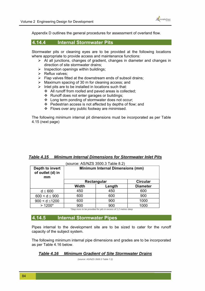
Volume 2 Engineering Design for Development
Appendix D outlines the general procedures for assessment of overland flow. 4.14.4 Internal Stormwater Pits Stormwater pits or cleaning eyes are to be provided at the following locations where appropriate to provide access and maintenance functions:
At all junctions, changes of gradient, changes in diameter and changes in direction of site stormwater drains;
Inspection openings within buildings; Reflux valves; Flap valves fitted at the downstream ends of subsoil drains; Maximum spacing of 30 m for cleaning access; and Inlet pits are to be installed in locations such that:
All runoff from roofed and paved areas is collected; Runoff does not enter garages or buildings; Long term ponding of stormwater does not occur; Pedestrian access is not affected by depths of flow; and Flows over any public footway are minimised.
The following minimum internal pit dimensions must be incorporated as per Table 4.15 (next page)
Table 4.15 Minimum Internal Dimensions for Stormwater Inlet Pits (source: AS/NZS 3500.3 Table 8.2)
Depth to invert of outlet (d) in
mm
Minimum Internal Dimensions (mm)
Rectangular Circular Width Length Diameter
450 450 600 d ≤ 600 600 600 900 600 < d ≤ 900 600 900 1000 900 < d ≤1200
> 1200* 900 900 1000 *Step irons to be provided for pits in excess of 1.2 metres deep
4.14.5 Internal Stormwater Pipes Pipes internal to the development site are to be sized to cater for the runoff capacity of the subject system. The following minimum internal pipe dimensions and grades are to be incorporated as per Table 4.16 below.
Table 4.16 Minimum Gradient of Site Stormwater Drains (source: AS/NZS 3500.3 Table 7.2)
84 Campbelltown (Sustainable City) Development Control Plan 2009 Effective 24 June 2009
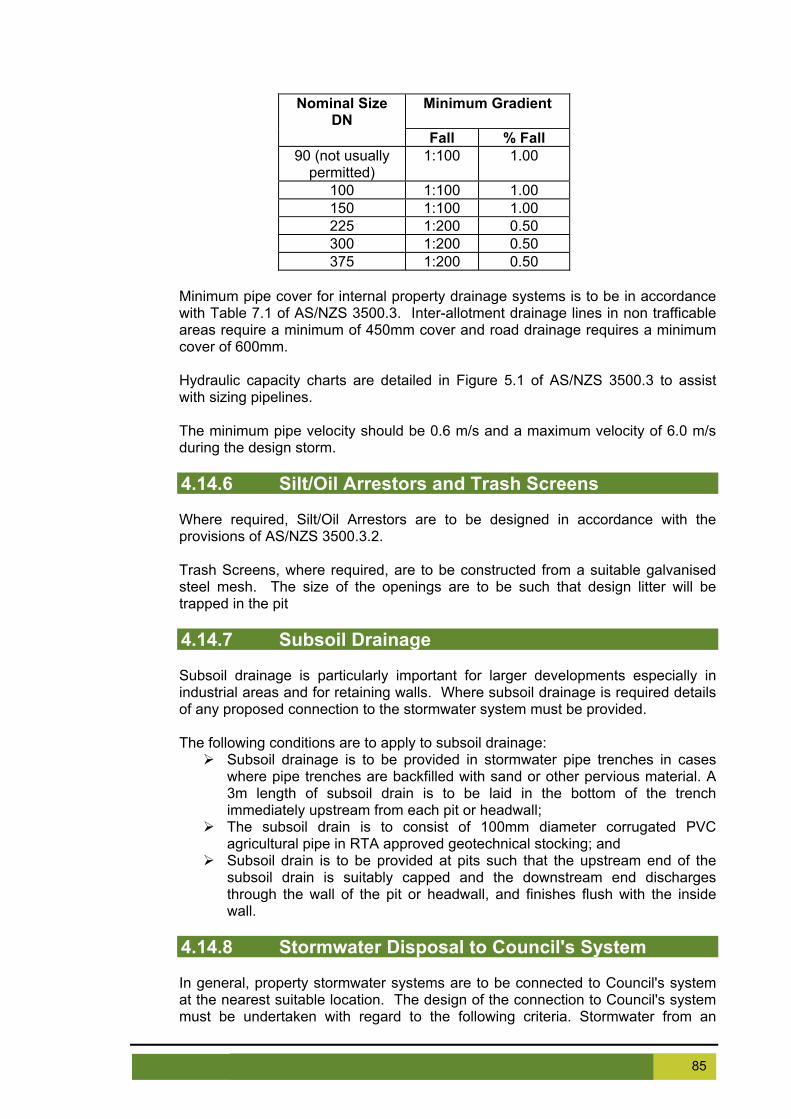
Nominal Size DN
Minimum Gradient
Fall % Fall 90 (not usually
permitted) 1:100 1.00
100 1:100 1.00 150 1:100 1.00 225 1:200 0.50 300 1:200 0.50 375 1:200 0.50
Minimum pipe cover for internal property drainage systems is to be in accordance with Table 7.1 of AS/NZS 3500.3. Inter-allotment drainage lines in non trafficable areas require a minimum of 450mm cover and road drainage requires a minimum cover of 600mm. Hydraulic capacity charts are detailed in Figure 5.1 of AS/NZS 3500.3 to assist with sizing pipelines. The minimum pipe velocity should be 0.6 m/s and a maximum velocity of 6.0 m/s during the design storm. 4.14.6 Silt/Oil Arrestors and Trash Screens Where required, Silt/Oil Arrestors are to be designed in accordance with the provisions of AS/NZS 3500.3.2. Trash Screens, where required, are to be constructed from a suitable galvanised steel mesh. The size of the openings are to be such that design litter will be trapped in the pit 4.14.7 Subsoil Drainage Subsoil drainage is particularly important for larger developments especially in industrial areas and for retaining walls. Where subsoil drainage is required details of any proposed connection to the stormwater system must be provided. The following conditions are to apply to subsoil drainage:
Subsoil drainage is to be provided in stormwater pipe trenches in cases where pipe trenches are backfilled with sand or other pervious material. A 3m length of subsoil drain is to be laid in the bottom of the trench immediately upstream from each pit or headwall;
The subsoil drain is to consist of 100mm diameter corrugated PVC agricultural pipe in RTA approved geotechnical stocking; and
Subsoil drain is to be provided at pits such that the upstream end of the subsoil drain is suitably capped and the downstream end discharges through the wall of the pit or headwall, and finishes flush with the inside wall.
4.14.8 Stormwater Disposal to Council's System In general, property stormwater systems are to be connected to Council's system at the nearest suitable location. The design of the connection to Council's system must be undertaken with regard to the following criteria. Stormwater from an
85 Campbelltown (Sustainable City) Development Control Plan 2009 Effective 24 June 2009
Volume 2 Engineering Design for Development
industrial development will be connected to Council’s piped drainage system. Connection to street kerb and gutter will not be permitted for an industrial development. Kerb and Gutter Connections to street kerb and gutter are to be made via a 150 x 50 galvanised RHS kerb adaptor. The invert of the outlet pipe is to be placed 10 mm above the invert of the kerb. Multiple connections to the kerb will require the provision of a lintel over the outlet pipes. See SD-R06 for details. If site discharge is greater than the capacity of the kerb outlet, a direct connection will be required to Council's underground pipe system. Council's Piped Drainage System Where stormwater disposal cannot be facilitated by direct connection to Council's piped trunk drainage system, connection to the system will be permissible by means of connection to an existing pit or construction of a new pit to Council's specification. In some instances the installation of an appropriate slope junction may be approved. Council will endeavour to keep the number of connections into its underground drainage system to a minimum. Connecting to existing pits is the favoured method of connection. Pipes connected to existing pits are to be cut flush with the internal wall of the pit. The pipe should enter the pit perpendicular to the pit wall and all damage to the internal wall of the pit around the pipe connection is to be repaired to the satisfaction of Council's Development Engineer. A bond will be taken for such works, prior to the issue of a Construction Certificate. New pits are to be constructed in accordance with Council's SD-S06 or other plans approved by Council. A separate engineering Construction Certificate will be required for construction of a new street pit. For property drainage systems up to 225 mm diameter, Council may consent to connection to an existing Council drainage line via a slope junction providing Council's pipe diameter is at least three times greater than the proposed connection. Only one slope connection is permissible from the development to Council's system. The connection is to be made good to the satisfaction of Council's Development Engineer. A bond will be taken for such works, prior to the issue of a Construction Certificate. All connections between pipes, where no junction pits are provided, the obverts of the pipes are to be matched and the connection is to be at a maximum angle of 60o to the direction of flow Extension of Council's Street Drainage System Consideration will be given to the extension of Council's system along a public road to facilitate disposal of stormwater from the property. A Kerb inlet pit will need to be constructed at the junction of the internal drainage and extended street system. The extended system is to be a minimum 375-diameter rubber ring jointed reinforced concrete pipe. Council’s written approval for all works involving extension of Council's Street drainage system will be required. Full hydraulic details are to be undertaken in accordance with this Guide.
86 Campbelltown (Sustainable City) Development Control Plan 2009 Effective 24 June 2009
4.14.9 Inter-allotment Drainage Where the land falls away from the road or there is no provision for drainage to the street, the developer will be required to provide inter-allotment drainage to carry the stormwater from the development to Council's drainage system unless the land drains to an area of Public Reserve or open space, where Council may require connection as detailed in Section 4.14.8. Approval from Council’s Manager Property and Support Services is required for discharge to pipes within Council owned land. Inter-allotment drainage for subdivisions creating separate lots for detached housing is to be designed to carry the 1 in 5 year average recurrence interval storm flows generated by assuming an appropriate percentage of the lot area is impervious (for guidance see Section 4.13) and drained by the drainage line. Inter-allotment drainage for other developments is to be designed to carry the 1 in 5 year average recurrence interval storm flows for the total site area, where there is a suitable overflow path. A pit is to be provided at the downstream corner of each industrial lot. The minimum size of the stub connection is to be 375mm diameter. Stub pipes are to be either concrete or FRC. Minimum width of easement for industrial inter-allotment drainage or where water from a public area is being conveyed should be 2.5 metres. Pipes are to be designed to flow full at the design discharge without surcharging of inspection pits.
87 Campbelltown (Sustainable City) Development Control Plan 2009 Effective 24 June 2009

Volume 2 Engineering Design for Development
All stormwater designs are to accommodate the major flows in excess of the piped drainage system capacity, up to the 100-year ARI event. The design plans are to indicate the location and extent of all overland flow paths required for such flows. A full hydraulic analysis of the flow paths is to accompany the engineering plans. A Restriction as to User is to be created on the title of lot/s prohibiting the alteration of the surface levels and structures within the drainage easement and limiting fencing across the easement to allow overland flow to be contained within the easement. Should it be required to drain the proposed development/subdivision through private property, the subdivider will be required to register a suitable easement over the downstream properties with Land & Property Information NSW prior to approval of the engineering plans for the subdivision/development. The easement width is to be in accordance with Council's standard easement widths (see Section 4.21). Common drainage lines are to be located centrally within an easement and are to be located in the higher rather than the lower property. Full design information for all inter-allotment drainage is to be provided with the plans submitted for approval. The plan of inter-allotment drainage and supporting information is to provide the following:
Plan & Long-section including appropriate invert and surface levels; Connection detail to Council system; Survey details of easement including all structures/ features in the vicinity; Documents confirming easement is registered in favour of the land to be
developed; Details of flow path for flows in excess of the pipe capacity; and Hydraulic Grade Line analysis for large inter-allotment drains.
Inspection pits are to be provided on inter-allotment drainage lines at the following locations:-
At the upstream end of all lines; At all changes in horizontal and/or vertical alignments; and At all changes in pipe sizes.
Pipe sizes are to be based on a 5-year ARI design flow or 18 L/s per lot (whichever is greater), subject to a minimum size of 150mm diameter. In the absence of a drainage analysis for the common line, the easements are to piped in accordance with the requirements set out in Table 4.17. A cleaning eye junction to be provided at the lowest point of each lot. Pipes are to be laid on their barrel with minimum cover of 300 mm with straight grades between cleaning eye junctions and/or junction pits. The minimum grade allowable is 1 in 100.
Table 4.17 Inter-allotment Drainage Pipe Sizes Number of houses Minimum Pipe size
One house only 100 mm diameter 2 – 4 houses 150 mm diameter 5 – 8 houses 230 mm diameter
9 – 15 houses 300 mm diameter * 16 – 25 houses 380 mm diameter *
88 Campbelltown (Sustainable City) Development Control Plan 2009 Effective 24 June 2009

* Approval must be obtained from Council’s Development Engineer. It is preferable to discharge these lines to Council's System before flows get this large
Inter-allotment drainage pits are to be provided at all changes of direction, grade or pipe size and at junctions or as required by Council and spaced no further than five (5) lots or 75m, whichever is the shortest distance. The internal dimensions of pits are to be in accordance with Table 4.15 in Section 4.14.4. The conversion from the inter-allotment pipe to the steel sections is to be achieved by the construction of an inspection pit inside the property boundary. Pre-cast concrete pits may be used for Inter-allotment drainage within residential lots. Prior to the issue of an Occupation Certificate or Subdivision Certificate, the developer will be required to submit certification from a registered surveyor stating that all pipes, pits and associated structures are constructed wholly within their respective easements. Minimum cover for pipelines within allotments is 300mm, apart from footway crossings to kerbs with galvanised steel Rectangular Hollow Sections (RHS). Slope junctions will be provided at the low point of each lot where no pit is provided. All inter-allotment pipelines to have rodding eyes immediately downstream of all slope junctions. Inter-allotment drainage is to be contained within an easement sized in accordance with guidance provided in Section 4.17, provided in favour of the upstream allotments, with Council as the Authority empowered to vary, modify or release. Inter-allotment drainage is to be constructed from rubber ring jointed pipes of either fibre reinforced concrete drainage pipe, reinforced concrete pipe, or UPVC pipe, which conform respectively to the requirements of AS 4139, AS 4058 and AS 1254. In public road and recreation reserves where vehicle loads may be encountered, reinforced or fibre reinforced concrete pipe minimum Class 3 only, are to be used. Where inter-allotment drainage and sewer mains are laid adjacent to each other they are to be spaced a minimum of 1.5 metres between pipe centrelines (where the pipe inverts are approximately equal). Where there is a disparity in level between inverts the spacing is to be submitted for approval. Where sewer mains are in close proximity to inter-allotment drainage lines they are to be shown on the inter-allotment drainage plan. 4.14.10 Alternative Solutions Council will consider alternative solutions where stormwater disposal cannot be achieved by a conventional gravity drainage system and where there has been a genuine attempt to gain an easement through all possible downstream properties and that this is confirmed through a signed letter from the owners of downstream properties or as a result of a decision made in the Land and Environment Court. Council will not support proposals that will have a negative impact on adjoining properties. There must be no potential for overflows or failure of any proposed system to impact upon downstream properties Options and opportunities must be investigated by the applicant and submitted to Council for approval.
89 Campbelltown (Sustainable City) Development Control Plan 2009 Effective 24 June 2009

Volume 2 Engineering Design for Development
In order for Council to support an alternative solution, it is required that plans and details submitted at the development application stage contain a high level of detail. The design of any alternative solution is to include all details as required under the Checklist in Appendix A. Depending upon the option proposed, the following information is required to be submitted as supporting documentation to the stormwater drainage design. Landscape and paving plan - Will be required to demonstrate that the amount of paved area has been limited as far as possible, and suitable landscaping has been proposed to prevent future paving. In general paved drained areas are to be less than 50 m2. Covenants may be imposed over pervious areas to restrict paving of these areas. Structural plans for slab/ foundations - This will be required where proposed stormwater lines are located beneath the dwelling. Architectural elevations showing stormwater lines - This will be required where elevated lines are proposed.
4.15 Stormwater Quality It is not the aim of this document to give guidance in the design of Water Quality devices. The range and availability of proprietary devices and first principles designs is too great to cover. With the exception of WSUD elements (see next section), it is anticipated that small developments (1 or 2 lots) will not require water quality controls. Stormwater quality objectives are to be met by the installation of water quality treatment devices and natural systems for all of the following developments:
Any industrial development ≥ 2500 m2; Any commercial development ≥ 2500 m2; Residential development ≥ 10 lots; and Any development adjoining a watercourse will require special treatment, however
each application will be assessed on merit. In general local stormwater quality objectives are set in Campbelltown City Council’s Stormwater Management Plans. More general objectives are found in the following references.
NSW Department of Environment and Climate Change (DECC) is currently revising the Managing Urban Stormwater suite of documents. Draft and final documents have been released: these documents are to be followed;
WSUD in the Sydney Region; WSUD Technical Guidelines for Western Sydney; Australian Runoff Quality; Council’s Stormwater Management Plan/s; and NSW Water Quality and River Flow Objectives for the Georges River Hawkesbury Nepean Catchment Action Plan Objectives.
Where specific advice cannot be found relating to a site or the environment management objectives of downstream receiving waters, adopting 80%, 45% and 45% reduction in TSS, TP and TN loads respectively for new development will apply. This is the least preferred approach, as its use does not reflect the needs of different receiving environments.
90 Campbelltown (Sustainable City) Development Control Plan 2009 Effective 24 June 2009

The following general objectives will also apply:
A treatment train approach to water quality should be used; Systems must be designed to take into consideration local and site conditions; Designs must be functional and aesthetically pleasing; and Maintenance requirements must be considered in terms of both plant equipment
required and occupational health and safety issues for staff. Water quality treatment measures will consist of a range of devices suited to the types of pollutants leaving the site and may include but not be limited to:
trash racks; gross pollutant treatment devices; oil and grit separators; booms; wetlands; bioribbons; and first flush systems.
Infiltration systems, absorption trenches and porous paving systems are not generally considered appropriate for use in Campbelltown because of issues with impervious clays and generally high levels of saline groundwater. Constructed wetlands and open water bodies will be assessed on merit. All bioribbons and wetlands are to be fully lined with an impermeable membrane (not clay) and isolated from the natural groundwater. Guidance on the design of these devices can be found in the following references:
Water Sensitive Urban Design in the Sydney Region Resource Kit 2003; Water Sensitive Urban Design Technical Guidelines for Western Sydney 2004;
and NSW Department of Environment and Climate Change (DECC) is currently
revising Managing Urban Stormwater Treatment Techniques. Once this document is released, the guidance therein should be followed.
4.16 Water Sensitive Urban Design Water Sensitive Urban Design (WSUD) is a relatively new approach to water management in urban areas. The objective of WSUD is to maintain or replicate the natural water cycle through the use of design techniques to create a functionally equivalent hydrological landscape. The aims are to optimise the use of rainwater that falls on the site and to minimise the amount of water transported out of the catchment resulting in a reduced demand for potable water. Generally, Council will require the use of WSUD measures only for those types of development set out in Section 4.15. WSUD may be applied to new or existing streets and developments, to public or private property. In general, Council prefers the utilisation of WSUD elements in the public domain where maintenance and continued operational efficiency can be managed. The following references may assist in the consideration of WSUD options:
Managing Urban Stormwater (draft and final documents issued by DECC); Water Sensitive Urban Design in the Sydney Region Resource Kit 2003; Water Sensitive Urban Design Technical Guidelines for Western Sydney 2004; Australian Standard AS/NZ 3500.3 Plumbing and Drainage (Stormwater
Drainage);
91 Campbelltown (Sustainable City) Development Control Plan 2009 Effective 24 June 2009

Volume 2 Engineering Design for Development
Australian Rainfall & Runoff; Australian Runoff Quality; Building Code of Australia Housing Provisions (current edition); Campbelltown Sustainable City Development Control Plan Volume 1; Map of Salinity Potential in Western Sydney 2002; Guidelines to accompany Map of Salinity Potential in Western Sydney 2002; WSROC Western Sydney Salinity Code of Practice 2004; DIPNR Local Government Salinity Initiative Publications (various); The relevant Government adopted or interim Water Quality Objectives (WQOs); Any relevant statutory constraint (eg classified water under the Clean Water
regulation or the riparian vegetation protection measure provided by the Water Management Act, 2000;
Any environmental flow objectives endorsed by Government or being developed through any Government established forums;
NSW Water Quality and River Flow Objectives for the Georges River Hawkesbury Nepean Catchment Action Plan Objectives. The requirements of any catchment or waterway focussed environmental planning
instrument (SEPP/SREP); and The Hawkesbury-Nepean Statement of Joint Intent, which provides much of the
context for the sub-catchments within Menangle Park. Much of this is concerned with wastewater management but there are some relevant Water Quality Objectives that are useful to design stormwater system that would achieve these targets.
Any proposal to incorporate WSUD measures into a new development is to be submitted to Council for consideration with the Development Application. It is recommended that the applicant liaise with Council's Manager Environmental Planning for site-specific requirements which may be imposed. In the context of Water Sensitive Urban Design (WSUD), specific elements will seek to manage the following issues:
Water quality; Flooding; and Environmental flows.
The key planning and design objectives are:
Protect and enhance natural water systems in urban developments; Integrate stormwater treatment into the landscape by incorporating multiple-use
corridors, that maximise the visual and recreational amenity of the development; Systems that are aesthetically pleasing; Protect water quality draining from development areas; Reduce runoff and peak flows from developments by employing local detention
measures, minimising impervious areas and maximising re-use (for example through rain water tanks);
Stormwater management must form a key component in the overall water cycle management for the site;
Add value while minimising drainage infrastructure development and maintenance costs;
Retention of vegetation on site; Retention of riparian and habitat corridors for the movement of fauna; Use of indigenous (local) vegetation; and Community involvement, understanding and appreciation of the environment.
92 Campbelltown (Sustainable City) Development Control Plan 2009 Effective 24 June 2009

WSUD initiatives must not impact on the local groundwater in terms of either quantity (including water table levels) or quality.
93 Campbelltown (Sustainable City) Development Control Plan 2009 Effective 24 June 2009

Volume 2 Engineering Design for Development
Specific strategies may include:
Orientation of roads to traverse across contours, providing slopes with relatively flat grades, to promote the provision of treatment measures into the streetscape;
Promote cluster lot arrangements around public open space to promote community access to natural and landscaped water features, provided for stormwater management;
Provide for the maintenance and re-establishment of vegetation along waterways, and provide public open space along drainage lines to develop multi-use corridors linking public and private areas;
Preserve and restore (if required) existing valuable elements of the drainage system (e.g. natural channels, wetlands, riparian vegetation);
Manage the quality and quantity of stormwater at or near the source, which will involve a significant component of public education and community involvement;
Provide treatment practices such as” treatment trains” and wetlands to manage water quality, downstream or close to the point of discharge of upstream catchments;
Provide ‘structural’ stormwater quantity and quality management practices that provide flood management, flow attenuation, flood volume reduction, and water quality management. These are typically in the form of detention basins, lakes and ponds, wetlands, rehabilitated waterways and appropriate water reuse schemes;
Provide primary stormwater treatment measures, which target litter, gross pollutants and coarse sediments and secondary treatment measures, which target sediment, nutrients and bacteria; and
Provide opportunities for community stewardship of the stormwater system. The realisation of an effective WSUD scheme requires adequate land to be set aside for the treatment measures at the Masterplanning stage. If adequate land is not set aside at this time, it will be almost impossible to accommodate the devices in a conventional planning scheme. The following issues may require early consideration in WSUD schemes:
Public Open Space – in terms of location and composition; Housing Layout – needs to integrate residential blocks with the stormwater
function and public open space. Flood protection must be ensured; Road Layout – roads located beside public open space can be utilised to enhance
visual and recreational amenity and facilitate direct connection of stormwater; Streetscape Layout – a water sensitive streetscape integrates the road layout,
vehicular and pedestrian requirements with stormwater management needs; and Design consistent with the principles of Safer by Design.
Figure 4.9 shows the general differences between a conventional development and a water sensitive urban development. The following illustrates the general procedure that will apply to the design of WSUD developments.
Determine treatment objectives - establish the pollutants of concern in the catchment (e.g. litter, sediments, and nutrients) and the level of pollutant retention required;
Develop a treatment train solution– assess the treatment processes required and appropriate measures and ordering, including any pre-treatment requirements (e.g. screening of coarse sediments or flow control).
Identify suitable sites – assess potential sites and site constraints (e.g. slopes and soil types);
Short-list alternative treatments – identify all applicable treatments;
94 Campbelltown (Sustainable City) Development Control Plan 2009 Effective 24 June 2009
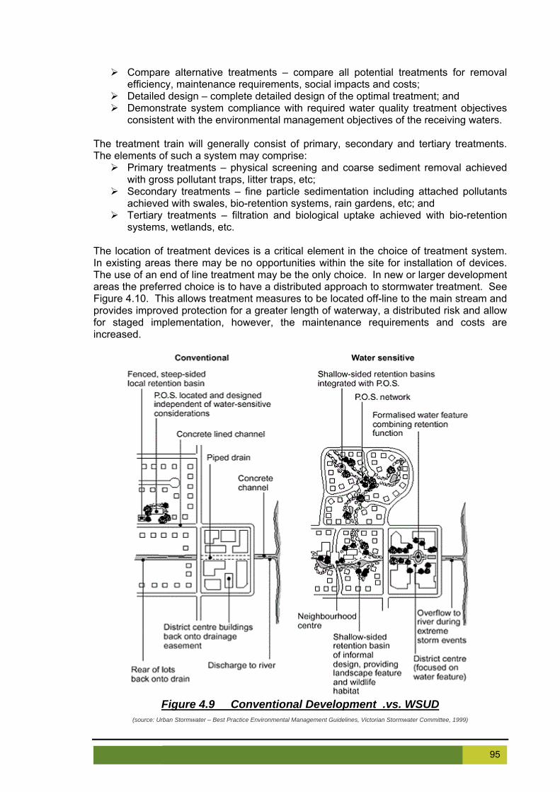
Compare alternative treatments – compare all potential treatments for removal efficiency, maintenance requirements, social impacts and costs;
Detailed design – complete detailed design of the optimal treatment; and Demonstrate system compliance with required water quality treatment objectives
consistent with the environmental management objectives of the receiving waters. The treatment train will generally consist of primary, secondary and tertiary treatments. The elements of such a system may comprise:
Primary treatments – physical screening and coarse sediment removal achieved with gross pollutant traps, litter traps, etc;
Secondary treatments – fine particle sedimentation including attached pollutants achieved with swales, bio-retention systems, rain gardens, etc; and
Tertiary treatments – filtration and biological uptake achieved with bio-retention systems, wetlands, etc.
The location of treatment devices is a critical element in the choice of treatment system. In existing areas there may be no opportunities within the site for installation of devices. The use of an end of line treatment may be the only choice. In new or larger development areas the preferred choice is to have a distributed approach to stormwater treatment. See Figure 4.10. This allows treatment measures to be located off-line to the main stream and provides improved protection for a greater length of waterway, a distributed risk and allow for staged implementation, however, the maintenance requirements and costs are increased.
Figure 4.9 Conventional Development .vs. WSUD
(source: Urban Stormwater – Best Practice Environmental Management Guidelines, Victorian Stormwater Committee, 1999)
95 Campbelltown (Sustainable City) Development Control Plan 2009 Effective 24 June 2009
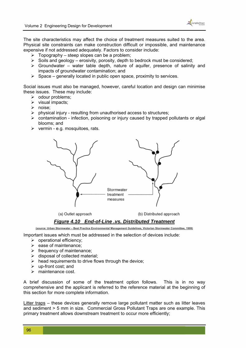
Volume 2 Engineering Design for Development
The site characteristics may affect the choice of treatment measures suited to the area. Physical site constraints can make construction difficult or impossible, and maintenance expensive if not addressed adequately. Factors to consider include:
Topography – steep slopes can be a problem; Soils and geology – erosivity, porosity, depth to bedrock must be considered; Groundwater – water table depth, nature of aquifer, presence of salinity and
impacts of groundwater contamination; and Space – generally located in public open space, proximity to services.
Social issues must also be managed, however, careful location and design can minimise these issues. These may include:
odour problems; visual impacts; noise; physical injury - resulting from unauthorised access to structures; contamination - infection, poisoning or injury caused by trapped pollutants or algal
blooms; and vermin - e.g. mosquitoes, rats.
Figure 4.10 End-of-Line .vs. Distributed Treatment
(source: Urban Stormwater – Best Practice Environmental Management Guidelines, Victorian Stormwater Committee, 1999)
Important issues which must be addressed in the selection of devices include: operational efficiency; ease of maintenance; frequency of maintenance; disposal of collected material; head requirements to drive flows through the device; up-front cost; and maintenance cost.
A brief discussion of some of the treatment option follows. This is in no way comprehensive and the applicant is referred to the reference material at the beginning of this section for more complete information.
itter trapsL – these devices generally remove large pollutant matter such as litter leaves Commercial Gross Pollutant Traps are one example. This
primary treatment allows downstream treatment to occur more efficiently;
and sediment > 5 mm in size.
96 Campbelltown (Sustainable City) Development Control Plan 2009 Effective 24 June 2009

Swales – appear as linear depressions. They function by collecting and conveying stormwater stripping out sediment and bound particles by physical and bio-chemical processes. They may be grass lined or more heavily vegetated and are generally
rovided within the roadway or carpark areas. Generally they will require an impermeable pmembrane separating them from the native soil; Infiltration Trenches – are shallow excavated trenches filled with gravel or rock. Runoff drains via these and processes similar to that in swales occur. The larger media allows
ore surface area for bio-chemical processes to occur. The presence of salinity in mCampbelltown will necessitate the use of impermeable liners with these trenches. Discharge points will have to be carefully considered; Bio-retention Systems – these systems use vegetation to reduce downstream flow elocities and to provide secondary treatment of runoff. Additionally, they provide a v
reduction in outflow or detention component; Sub-surface and Surface Wetlands – are provided as a series of distinct cells which
duce velocities, filter litter and use biological and chemical processes to polish restormwater. Compared to the methods above, a longer residence time is required for these systems; Porous paving – is used as an alternative to conventional impermeable paving and can
rovide similar benefits to infiltration trenches with the porous media providing treatment Campbelltown is unlikely to be supported because clays and salinity hazard;
psurface area. Use of porous paving in
f issues with impermeable, dispersiveo
ain gardensR – are designed to provide stormwater quality treatment in the form of an ornamental feature. They comprise selected growing media and vegetation for water quality treatment and depending on size can also provide detention storage; Rooftop greening – involves the establishment of a “green roof” using vegetation to filter stormwater runoff and may additionally be used to capture and store the runoff for reuse. This treatment is used extensively in Europe. It is generally only suitable for industrial and commercial developments. 4.17 Drainage Easements The standard easement widths are given in Table 4.18. Consideration may be given to the reduction of the required easement widths where it is demonstrated that the full easement width cannot be obtained and the proposed pipe can be installed, maintained and replaced satisfactorily within the reduced easement. Where multiple pipes are proposed a larger easement will be required. Where pits are required in easements the width is to be at least 600mm wider than the pit width. Wider
asements may also be required where the depth of pipes warrants such an approach for the future maintenance or r Where it is in inage easements on, a notation is to app the lin ment o ements pursuant to Sect Whe on other than to d nal” Council land (e.g. parks, recreation in accordance with Table 4.18 shall be created over the stormwater pipes. The applicant s liaise with Council’s
eepair of the pipeline.
tended ate dra to creear on
for a new road p ded in a subdivisirovir easen plan creating the ease
Act, 1919 as amended. ion 88B of the Conveyancing
re private developments have no opti rain to “non-operatio reserves, etc), drainage easements
hall
97 Campbelltown (Sustainable City) Development Control Plan 2009 Effective 24 June 2009

Volume 2 Engineering Design for Development
Property Secti r requirements which will require p nt of compensation and all of Cou
18 Easement W
on regarding thei aymencil’s costs.
Table 4. idths Pipe Diameter [D]
(mm) Width of Easement to Drain Water
(m) Inter-allotment drainage
Inter allotment drainage (residential) As below (min 1.5) Inter allotment drainage (industrial ) As below (min 2.5)
Easements for all other pipelines D ≤ 675 2.5
675 < D ≤ 900 3.0 900 < D ≤ 1200 3.5
1200 < D ≤ 1500 4.0 1500 < D ≤ 1800 4.5
D > 1800 and box culverts As required by Council Floodway Top width of (100 yr design flows +0.5 m
freeboard) + 1m [may increase where downstream
structures are present] Adjoining Owners Consent/Creation of Drainage EasementsWhere drainage involves the provision of drains, or at any concentration of stormwater, across land owned by others, evidence that the necessary easements have been created over the downstream properties must be lodged with Council. This evidence must be lodged with the initial set of engineering plans. Details of the easement and proposed works must be shown on the engineering plans and downstream owners consent to carry out the proposed works. Easements must be registered prior to approval of the engineering plans.
essed by an independent person to be submitted prior to any approval of the engineering plans. See Appendix G.
above requirements have been complied with, and ll fees and contributions have been paid.
ubdivision and execute a transfer and grant of easement in favour of Council pursuant to
avour at the
Where an agreement is reached with an adjacent landowner to increase flood levels on his property or otherwise adversely affect his property, a letter signed by all the landowners outlining what they have agreed to and witnis Where stormwater is concentrated or discharged onto adjoining lands other than an existing easement or natural watercourse, it is the responsibility of the developer to obtain a drainage easement through such land, sufficient in dimension to convey the drainage to an easement or natural watercourse, and to transfer easement rights to Council. The linen plan of subdivision will not be released until the a Where a drainage easement lies within a development which does not involve the opening of a new road, the developer is to transfer to Council any drainage easement provided in thesSection 88B of the Conveyancing Act, 1919 as amended. Where piped stormwater drainage discharges to recreation reserves or other Council land an approved outlet structure must be provided. Drainage lines proposed to cross either existing or proposed non-operational Council land will require specific prior Council consent in writing and, if approved, a drainage easement in Council's f
98 Campbelltown (Sustainable City) Development Control Plan 2009 Effective 24 June 2009

applicant's expense is to be provided. The applicant should liaise with Council's Manager
No or stormw er draina . Struc ise a pie ther approved method designed by a suitably qualified practicing structural engineer. The oad is to be transferred to below the invert of existing pipelines and/or channels within the easement. The zone of influence is considered to be defined by an envelope 45o from a tangent line at the level of the invert of the pipe at the easement boundary to the closest part of the structure (generally the footings).
Property Services at the design stage.
encroachments or overhangs are permitted over drainage lines or within easements fater drainage. Council may allow light, easily removable structures to be built ov
ge easements. eg carports or paved areas (complying with Council’s DCP Volume 1)
tures, such as houses and pools, adjacent to an easement are to be designed to utilr and beam system of footing or o
l
Figure 4.11 Zone of Influence
he overall width of the easement is such as to contain the full width of
Dra nage
To
overland flow, or pen ch d any access track if required by ounci
Plantindetailed in
annel flow in the major system design event, anl. C
g within drainage easements is permissible. Suitable and unsuitable species are
Appendix H.
4.18 Pu Safety willPhysical refeetc while perpetration
blic Safety – Stormwater and Drainage Easements
be considered for all applications from two standpoints: physical and criminal. rs to items such as risk of fall, risk of being swept away, dry weather hazards,
criminal refers to the opportunities that such systems may present for the of crime, especially providing areas of concealment.
4.1
The ph ents which Council will assess, include but are not limited to: the flood
o meet all applicable safety standards, regulations and criteria;
8.1 Public Safety – Physical
ysical elem A designated system of escape routes for events in excess of
planning level (100 year ARI) must be provided; Structures other than light, removable structures and paving, complying with Council policy, will not be permitted over drainage lines or within easements;
Open stormwater systems and their components are to be designed t
Pipe invert level at edge of easement
Footings to be extended to the Building footings
influence
extend below the zone of
invert level of pipe or to solid rock 45o
ieasement
Zone of Influence
99 Campbelltown (Sustainable City) Development Control Plan 2009 Effective 24 June 2009

Volume 2 Engineering Design for Development
The possibility of failure of components of the system must be considered
and provision made for the safe conveyance of flows should failure occur;
n basins are to have maximum 6H:1V batters and wetlands or
f maximum 6H:1V; the 20-
ceptable. In that case the provision of safety refuge
icators should be provided indicating maximum depth in basins; undertaken to reduce
al hazard
so that no ponding of water occurs on to private property or roads;
basin walls is allowed;
equired
ided; ntion basins;
applicable situation
elocity-Depth Relationship
Potential obstructions to the flow path must be minimised; Dry detentiowet basins are to have maximum 8H:1V batters above and below the waterline;
Grassed channels should have batter slopes o Water depths in basins are to be, where possible, less than 1.2m in
year ARI storm event. Where neither practical nor economical, greater depths may be acmounds should be considered; Depth ind
Protection of the low flow intake structure is to behazards for people trapped in the basin;
Signage of the spillway is necessary to indicate the additionpresented; Basins are to be designed
No planting of trees in No basin spillway is to be located directly upstream of urban areas; Submission of design plans to the Dam Safety Committee is r
where warranted; Major inlet structures and headwalls etc are to have suitable safety fencing
erected; Appropriate signage and fencing is to be prov A designated spillway must be provided for dete Maintenance requirements must not put Council staff at risk; and
Velocity depth relationship must be considered for the(discussed further below).
V
been copied from the NSW Floodplain Management Manual. The rinciples in this figure will form the basis of assessment for stability. Each
location will be required to meet the appropriate criteria for stability. As examples: No velocities above 2.0 m/s are appropriate; No depths greater than 2.0 m are appropriate; If the velocity in a roadway is predicted to be 1.0 m/s the depth can be up
to 0.25 m deep before vehicles become unstable; and A pathway with the same velocity of 1.0 m/s can carry a water depth of 0.5
m before pedestrians have trouble wading. Other criteria may govern and must also be considered. e.g. the pathway above may not be able to carry 0.5m depth of flow without impacting on adjoining properties.
The relationship between velocity and depth has long been considered an appropriate measure of stability for vehicles and pedestrians. Figure 4.12 below has p
100 Campbelltown (Sustainable City) Development Control Plan 2009 Effective 24 June 2009

Figure 4.12 Velocity Depth Relationship
(Source: NSW Floodplain Management Manual, 2001)
101 Campbelltown (Sustainable City) Development Control Plan 2009 Effective 24 June 2009

102 Campbelltown (Sustainable City) Development Control Plan 2009 Effective 24 June 2009
Volume 2 Engineering Design for Development
These criteria must be assessed when determining the capacity requirement for the minor system. The major system may only carry flows that meet the applicable velocity depth requirements. The limiting velocity depth relationship does not apply to Council’s designated floodways, channels, creeks, streams and rivers.
4.18.2 Public Safety – Criminal All stormwater structures and system elements will be assessed using the NSW Police “Safer by Design” or Crime Prevention through Environmental Design (CPTED) principles and protocols. The development proposal must demonstrate how public safety and risk will be managed. The following will be considered in the assessment of proposals (this list is not exhaustive and requirements will vary from site to site):
System elements which provide concealment opportunities will not be permitted;
Vegetation which provides opportunities for concealment adjoining pedestrian areas will not be permitted; and
Underground pipe and pit systems which are large enough for children to get into must be screened (with due consideration given to flooding implications).
4.19 Rainwater Tanks Rainwater tanks may be used to allow development to comply with the requirements of BASIX. In this section “rainwater tank” means a tank specifically designed to store rainwater either as a separate unit or attached to a building, including those that store rainwater in the eaves of a dwelling. Rainwater tanks must be installed in accordance with the following:
Guidelines for rainwater tanks on residential properties. Plumbing requirements published by Sydney Water (as amended);
Guidelines for Plumbing Associated with Rainwater Tanks in Urban Areas published in Committee on Uniformity of Plumbing and Drainage Regulations Circular P&D No. 18 (as amended); and
AS/NZS 3500.1.2: Water Supply – Acceptable Solutions and AS3500 – National Plumbing and Drainage Code (as amended).
These publications specify requirements for:
First flush diversion devices; Domestic plumbing requirements; Backflow prevention devices; Pumps; Suitable qualifications for installers; Allowable uses; and Potable top-up.

Other issues which must be considered are: Installation must be in accordance with any manufacturers instructions; Top up inflow should occur until the tank is 80% empty. Top up should not be
more than 20% of the total tank volume; Tanks must not be located over easements; Overflow from tanks must be directly plumbed to the stormwater system; Tanks must be screened to prevent entry of mosquitos and debris; and Pumps may be installed on rainwater tanks and must not create offensive noise as
defined in the Protection of the Environment Operations Act 1997 (generally no more than 5 dBa above ambient levels). Pumps may be required to be enclosed in a suitably designed acoustic enclosure.
In accordance with Council’s DCP and relevant Plans of Management, rainwater tanks must be installed for industrial and commercial land uses and amenities associated with open space and community facilities. The size of storage required for these land uses will be determined in consultation with Council. 4.20 Visual Impact All components of the stormwater system are to be designed to be visually unobtrusive and sympathetic with the development and it’s surroundings. Council will consider the effects on landscaping and heritage aspects of the site. 4.21 Froude Value It will be necessary to demonstrate that all stormwater elements are operating with an appropriate Froude value. Generally council will require a Froude value less than 0.8 in natural or naturalistic systems. An appropriate Froude value for formalised systems must be determined in consultation with Council. Where hydraulic jumps are predicted, adequate protection must be provided upstream and downstream of the predicted jump location. The sensitivity of jump location with variation in stream parameters must be investigated. 4.22 Sensitivity Analysis Where it is reasonable to expect that a stormwater element may perform within a range of values over its lifetime, it will be necessary to consider the range of values which may occur. For example, the Manning’s “n” value of a vegetated swale may be high when just established, but low once the vegetation has grown and bushes can be undercut leaving clean trunks. In this instance it will be necessary to model the swale with both the high and low values as the low Manning’s is critical for velocity controls while the high Manning’s value is critical for depth controls. Both the higher velocity and the deeper depth must be designed for as they represent different states in which the swale must operate during its design life. Sensitivity may be required for, but not limited to:
Manning’s “n” or other measures of catchment or channel roughness; Link lags; Time of concentration; and Locations of hydraulic jumps.
103 Campbelltown (Sustainable City) Development Control Plan 2009 Effective 24 June 2009

104 Campbelltown (Sustainable City) Development Control Plan 2009 Effective 24 June 2009
Volume 2 Engineering Design for Development
4.23 Maintenance It is essential that maintenance costs associated with stormwater assets which will be handed over to Council are minimised. It is also mandatory that assets must be able to be maintained with plant and equipment which Council owns or can lease as required. Management and annual (or periodic) maintenance requirements and costs for any system to be maintained by Council must be provided in the form of an Operating Manual by the applicant. 4.24 Design Life All stormwater infrastructure is to have a design service life of 100 years. This applies to pipes, pits and all structural elements. It is understood that natural/ naturalistic systems will be subject to natural impacts from weather and nature which are beyond the ability of the designer to account for. In respect of these elements of the stormwater system the above requirements regarding maintenance will apply.
4.25 Climate Change Climate change is occurring. Current predictions indicate that NSW will experience more intense rainfall with greater periods of dry weather between events. As such Council is requiring climate change to be considered for developments meeting any of the criteria below:
Any industrial development ≥ 2500 m2; Any commercial development ≥ 2500 m2; and Residential development ≥ 10 lots.
There are currently a range of possible climate change scenarios being proposed. Council requires assessment of the impacts on proposed and existing downstream development where the application meets the above criteria. The applicant is to examine the impacts of a 10% increase in all rainfall values in the rainfall hyetograph determined either from Australian Rainfall and Runoff or using the values in Appendix B of this DCP. This analysis is in addition to the analysis required using the standard values. Council is not requiring that stormwater systems be designed to accommodate these increased flows unless the analysis shows a significant deficit in the stormwater system without augmentation to address climate change flows. Each application will be dealt with on a case by case basis.

105 Campbelltown (Sustainable City) Development Control Plan 2009 Effective 24 June 2009
Table 4.6 Hydrological Design Sheet 1 PIPED URBAN STORMWATER DRAINAGE Sheet …… of …… Job …………………………………………………………………………………. Reference ………………………………………………..
(1) Pit
(2) Land Use Type
(3) Flow
Length (m)
(4) Slope (m/m)
(5) 'n'
(6) Time (min)
(7) Total Time (min)
(8) Intensit
y 1
(mm/h)
(9) Runoff Coeff.
C
(10) Area
A (ha)
(11) CA (ha)
[9]x[10]
(12) ΣCA (ha)
(13) Q=CIA
(l/s) [8]x[12] /0.36
(14) Bypass
Flow (l/s) from Pit( )
(15) Adopted
Flow rate (l/s) [13]+[14]
(16) Gutter Slope (m/m)
(17) Flow Width (m)
(18) Inlet Type
(19) Inflow (l/a)
(20) Bypass
Flow (l/s) to Pit ( )
(21) Remarks
FLOW TIMES PIT INLET
Designer …………………………… Date …………………. Checked ………………….

Volume 2 Engineering Design for Development
Table 4.7 Hydrological Design Sheet 2
PIPED URBAN STORMWATER DRAINAGE Job …………………………………………………. Reference ……………………….
(1) (2) (3) (4) (5) (6) (7) (8) (9) (10) (11) Pipe Time Intensity ΣCA Q= Time Intensity ΣCA Q=CIA Adopted Remarks
to I (ha) CIA to I (ha) (l/s) Flow Rate (min) (mm/h) (l/s) (min) (mm/h) [7]x[8] (l/s)
[3]x[4] /0.36 Greater /0.36 of [5] &[9]
FULL AREA PARTIAL AREA
Designer …………………………… Date …………………. Checked ………………
106 Campbelltown (Sustainable City) Development Control Plan 2009 Effective 24 June 2009

107 Campbelltown (Sustainable City) Development Control Plan 2009 Effective 24 June 2009
Table 4.11 Hydrological Design Sheet 3 PIPED URBAN STORMWATER DRAINAGE Sheet …… of …… Job ……………………………………………………………………………………. Reference ………………………………………………..
(1) Location
(2) Land Use Type
(3) Flow
Length (m)
(4) Slope (m/m)
(5) 'n'
(6) Time (min)
(7) Total Time (min)
(8) Intensit
y 1
(mm/h)
(9) Runoff Coeff.
C
(10) Area
A (ha)
(11) CA (ha)
[9]x[10]
(12) ΣCA (ha)
(13) Q=CIA
(l/s) [8]x[12] /0.36
(14) Cumulat-
ive Pit Capacitie
s (l/s)
(15) Down- stream Pipe
Capacity (l/s)
(16) Road Flow
rate [13]- lesser of
[14]&[15} (l/s)
(17) Road
Capacity
Check
(21) Remarks
FLOW TIMES
Designer …………………………………………… Date ……………………………………. Checked ……………………………

108 Campbelltown (Sustainable City) Development Control Plan 2009 Effective 24 June 2009
Volume 2 Engineering Design for Development
Table 4.12 Hydrological Checking Sheet PIPED URBAN STORMWATER DRAINAGE Job …………………………………………………. Reference ……………………….
(1) Pipe
(2) Leng
th L
(m)
(3) Design Flow- Rate
Q (l/s)
(4) Pipe Dia-
meter (m)
(5) Full Pipe Vel. V
(m/s)
(6) V22g (m)
(7) D/S HGL Level (m)
AHD
(8) Pipe
Friction Loss S L (m)
(9) HGL just
below U/S Pit
(m) [7]+[8]
(10) Obvert Level
At Upper End of Pipe (m)
(11) Pit
Pressure Change Coeffs.
K Or K
(12) K.V22g (m)
[11]x[6]
(13) Adopted U/S Pit Water
(or HGL) Level*
(m)
(14) U/S
Surface Level (m)
AHD
* (higher of [9] and [10] +[12])

109 Campbelltown (Sustainable City) Development Control Plan 2009 Effective 24 June 2009
Table 4.13 Table for Culvert Calculations Culvert Type ………………………………………. Job No. ………………………... Location ……………………………………………………………………………….. Parameter Com. Q1 Q2 Q5 Q10 Q20 Q50 Q100 Comments Q m3/s
Q/cell m3/s
Q/B m3/s.m
HW/D m
Fig. 3.3 or 3.4
Hwi m
A m2 R=W
AP m
Equiv. 4xR
R.C.P.=Q/(g.D2.5)0.5
S m/m
V.full m/s
Fig.1.8 to 1.11
Q.full m3/s
Vf x A
Q/Qf m3/s
Y/D m Fig.1.12 or 1.13 y m Depth of flow V/Vf Fig.1.12 or 1.13 V.outlet m/s
Vf x V/Vf
Dc critical d.
Fig.1.14 of 1.15 R.C.B.C. 4.67 (Q/B)2/3
(dc+D)/2 TW m
Est. from D/S data
L m
L1 m
Fig.3.5 or 3.6
H m
" " " "
LxS m
Friction loss
HWo m
(TW:dc2+D)+ H-LS
Hwi>Hwo? Control: Y=inlet N=Outlet U/S I.L. Design by ………………………… Checked ………………………… Approved ………………………… Date ……………………………… Datum …………………………… Plan No. ………………………….
Source: Culvert Control Check. Concrete Pipe Association of Aust. Hydraulic Design Manual.

Volume 2 Engineering Design for Development
Figure 4.1 Hydraulic Gradients
(Source: Hydraulics of Precast Concrete Conduits: Concrete Pipe Assoc of Australia, 1986)
110 Campbelltown (Sustainable City) Development Control Plan 2009 Effective 24 June 2009

Figure 4.2 Pit Loss Coefficients
111 Campbelltown (Sustainable City) Development Control Plan 2009 Effective 24 June 2009

Volume 2 Engineering Design for Development
Figure 4.3 Pressure Loss Coefficients cont.
112 Campbelltown (Sustainable City) Development Control Plan 2009 Effective 24 June 2009

Figure 4.4 Grated Kerb Inlet Independent of Grade
113 Campbelltown (Sustainable City) Development Control Plan 2009 Effective 24 June 2009

Volume 2 Engineering Design for Development
Figure 4.5 Inlet Capacities for Kerb Inlets in Sags
114 Campbelltown (Sustainable City) Development Control Plan 2009 Effective 24 June 2009

Figure 4.6 Inlet Capacities for Gratings in Sags
115 Campbelltown (Sustainable City) Development Control Plan 2009 Effective 24 June 2009

Volume 2 Engineering Design for Development
Figure 4.7 Inlet Capacities for Kerb Inlets with Durham Type Grates in
Sags
116 Campbelltown (Sustainable City) Development Control Plan 2009 Effective 24 June 2009
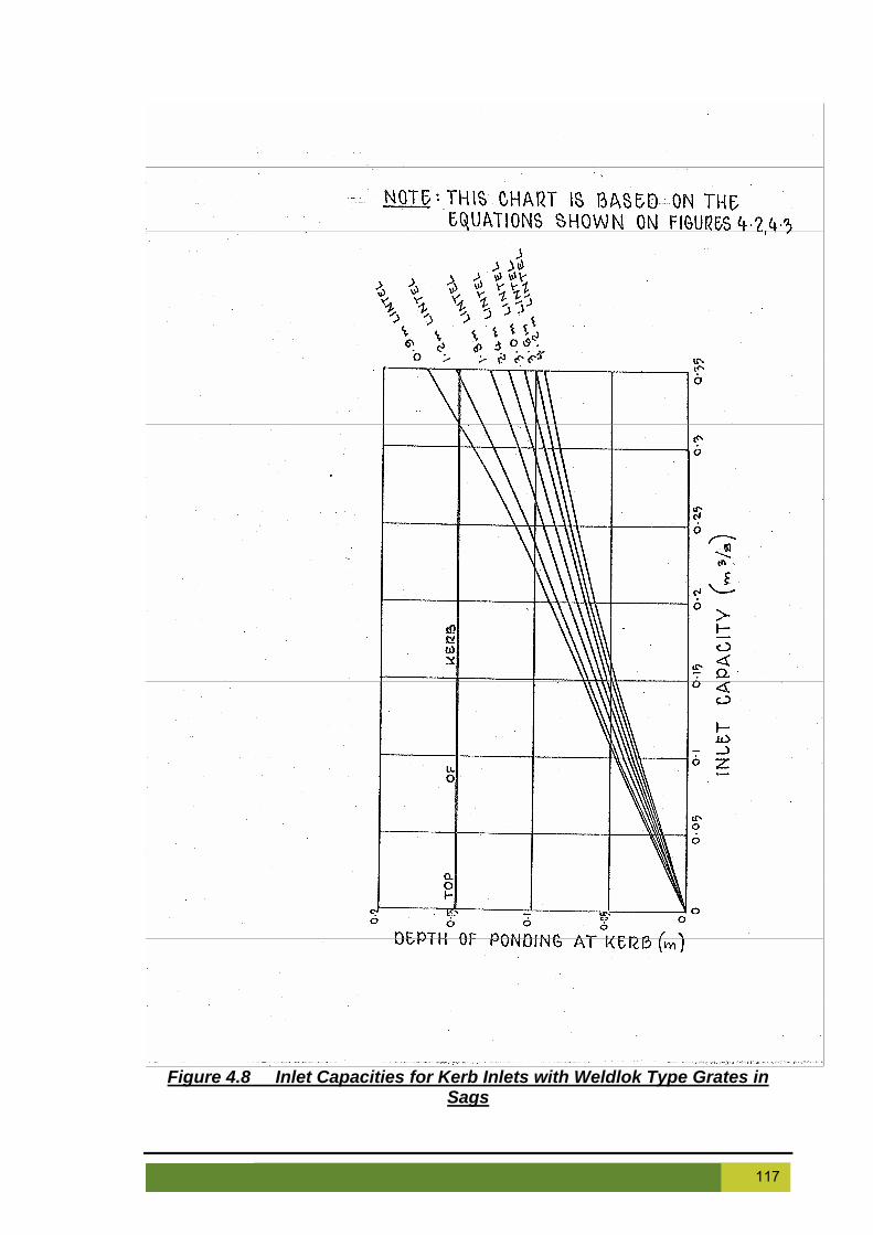
Figure 4.8 Inlet Capacities for Kerb Inlets with Weldlok Type Grates in
Sags
117 Campbelltown (Sustainable City) Development Control Plan 2009 Effective 24 June 2009

Volume 2 Engineering Design for Development
118 Campbelltown (Sustainable City) Development Control Plan 2009 Effective 24 June 2009

5 MISCELLANEOUS REQUIREMENTS 5.1 Scope This section of the engineering guidelines provides miscellaneous engineering requirements not covered in the previous sections. It also covers general issues which may apply to roadworks, stormwater infrastructure and development sites. 5.2 Aim To provide the Applicant with an understanding of other Council engineering requirements that may be required in the development of land, except in rural road situations. 5.3 Lot Cutting and Filling Council requires all areas of the site subject to cut and fill be identified and detailed on the engineering plans, submitted for approval. All imported fill material to be used must be tested and certified by a NATA registered laboratory. Placement of filling on the prepared areas shall not commence until approval has been obtained from Council. Filling shall be carried out in horizontal layers, extending the full width of the fill areas in not more than 250mm thick loose measurement layers. The dry density of fill is to satisfy the following requirements:
AS1289 - 5.6.1 Sands:- Density index more than 70% where compaction test is in accordance with the relevant Australian Standard;
AS1289 - 5.4.1 Material other than sand:- Dry density ratio of more than 98% Standard Maximum Dry Density where the compaction test is in accordance with the relevant Australian Standard;
All filled areas shall be certified as complying with the requirements of this provision by a N.A.T.A. registered Geotechnical Laboratory and the testing of such areas shall be carried out in accordance with the relevant A.S. provisions; and
The moisture content of each layer shall be maintained within –3% to +1% of optimum during compaction. Where it is necessary to increase the moisture content, each layer shall be watered by means of an approved sprayer delivering a uniform distribution of water over the area to be wetted. Adequate watering equipment shall be available during all compaction operations.
Each residential lot, whether filled or not, is to be classified in terms of Australian Standard for Residential Slabs and Footings (AS 2870). The lot classification is to be prepared by a N.A.T.A. registered geotechnical consultant. In cases where allotment site filling adjoins an existing lot boundary, the maximum height of fill and any retaining structure is not to exceed 800mm. Where approval is obtained to extend fill into adjoining properties (written consent is required), satisfactory arrangements must be made for the grading of the fill onto the land without ponding.
119 Campbelltown (Sustainable City) Development Control Plan 2009 Effective 24 June 2009

Volume 2 Engineering Design for Development
Revegetation must be applied immediately on completion of the site filling-regrading works. Council will require the imposition of a "Restriction on Use of Land" as part of the 88B instrument, identifying filled lots within the subdivision. Refer to Appendix F for standard wording. The minimum lot grading is to be 1% and a minimum 100mm of topsoil must be placed over all filled land. Filled land must be graded to ensure that no water is ponded. The minimum fill levels are to be to the level of the 100-year ARI flood level for all land. Where it is considered, from the grade and lie of the subject land, or adjoining lands, that roof and/or natural surface runoff may create future inter-allotment drainage problems, provision is to be made for piping, kerbing or land contouring to convey such water to the nearest drainage system under Council’s control. When dealing with applications involving earthworks consideration will be given to issues of amenity especially in terms of privacy and overshadowing for adjoining neighbours and aesthetics in terms of interruption of the natural landform. Developments proposing excessive filling will not be permitted. The following additional considerations will be given to fill proposals:
Proposed filling is to be compatible with services and easements in the near vicinity;
Proposed filling is to have regard to adjoining property in terms of upstream flows; Excessive filling will not be supported for the purposes of providing drainage for
land that falls away from the Council street system; All imported fill is to be accompanied by a validation report and Chain of Custody
Form for each load of fill delivered; A validation report is to confirm that the fill is suitable for the intended land use. All
imported fill is to be delivered and certified in accordance with the EPA's Guidelines for contaminated sites;
Filling is to be undertaken in accordance with Council's Specification for Construction of Subdivisional Road and Drainage Works; and
A Section 88B Restriction is to be placed on any land so burdened by fill. The following information must be provided with any Development Application for fill:
description and source of proposed fill material; detailed plans of the proposed filling; proposed methods to control erosion and sedimentation; proposed methods to control surface water flows on and around the site; proposed method of compacting fill; and proposed method of stabilising fill.
Fill material must have similar geotechnical properties to the surrounding natural material. Fill material must be Virgin Excavated Natural Material (VENM), as defined by DEC. Any fill involving material other than VENM is subject to referral to the State Government as potential Integrated Development or contaminated land assessment. The information provided must demonstrate that the following outcomes can be achieved:
the fill is suitable for and does not compromise the current and proposed end use of the subject land or adjacent land;
120 Campbelltown (Sustainable City) Development Control Plan 2009 Effective 24 June 2009

the cut or fill does not compromise the structural integrity of structures on the subject land or on adjacent land;
the cut or fill does not compromise the stability of the land; any cut or fill does not impede the drainage characteristics (surface and
subsurface) of the land external to the cut and fill boundaries and does not interfere with neighbouring properties;
there are no confirmed pollution incidents or any other deleterious impacts as a result of cutting or filling activities on site;
the cut or fill does not compromise the life span of vegetation on the site or on adjacent sites; and
any increase in ground level does not unacceptably affect the privacy of adjoining properties.
All filling in the vicinity of native vegetation must be local material (in order to minimise the spread of weeds). Fill over common drainage lines is allowed however overland flow must not be concentrated and any pits must be raised to the new ground level. Fill will not be permitted in designated flood ways or over a sewer or stormwater easement, against a boundary fence or over the roots of mature trees. Any fill proposal must comply with the following *:
minimum cross fall of 1%; batters no steeper than 6H:1V; and Any lots located on fill must have an 88B restriction regarding fill and include
notification on the S149 certificate;
* All applications for fill will be assessed on merit. Certification and Works as Executed plans prepared by a Registered Surveyor must be provided to ensure fill and floor levels for structures and facilities have been constructed in accordance with the approved plans. Certification of fill with respect to any advised fill level is to be undertaken by a Registered Surveyor prior to the continuation of construction above that level. For the purpose of creating a building platform for a dwelling, narrow lot housing and multi dwelling housing, the maximum level of cutting and filling should not exceed 500 mm cut and 500 mm fill, when measured at the corner of the building platform. Consideration will be given to varying this requirement where the application is accompanied by:
evidence produced by a qualified geo-technical engineer; appropriate structural engineers designs for retaining walls and site drainage; and demonstration that it does not adversely impact the adjoining property or the visual
amenity of the neighbourhood. Any application for cut in excess of 500 mm must be accompanied by a geotechnical investigation into the impacts of salinity on the site and of the site on local groundwater levels and salinity. 5.4 Safety Notation The applicant's attention is drawn to the responsibilities imposed under the Occupational Health & Safety Act.
121 Campbelltown (Sustainable City) Development Control Plan 2009 Effective 24 June 2009

Volume 2 Engineering Design for Development
For submission of engineering plans the applicant is required to make a full assessment of all safety aspects of the project and make appropriate notations on the plans to ensure the safety of the public and construction workers at all times. 5.5 Debris Disposal Burning off by open fire is prohibited by the provisions of the Protection of the Environment Operations Act NSW 1997, as amended. Disposal of all debris is to be to an appropriate registered facility in accordance with the Waste Management Plan prepared for the site. 5.6 Insurance
1. Public Liability Insurance: The Applicant must ensure that Contractors, engaged on Development or Subdivisional Works, have taken out Public Liability Insurance which must include the interests of Council to at least the value of $10 million dollars. Details of Insurance must be submitted to Council before work commences.
2. Workers Compensation: The Applicant must ensure that Contractors engaged on Development or Subdivisional Works carry current Workers Compensation Insurance on all works as required by Statute.
3. Professional Indemnity Insurance: The Applicant must ensure that the design engineer carries the appropriate level of Professional Indemnity Insurance
5.7 Fencing and Retaining Walls Fences on corner blocks must not obstruct the sight distance of traffic entering an intersection or roundabout or obstruct the ability to see traffic and must comply with minimum sight distances set out in Section 3.10. Suburb signposting is to be to Council’s specification and agreement. Suburb signs can remain within extra land provided within the road reserve Locality entry signs will be treated as advertising and are subject to Council’s advertising policy and fees. Such private signs (Estate signs) must be decommissioned following completion of development. Feature, suburb entry and subdivision signs must be individually approved by Council and are subject to negotiated conditions depending on location, scale, adjoining development and maintenance requirements Fences must not obstruct power, water, sewer, gas or telephone services, drainage systems, including overland flow paths, easements or rights of way. All fencing detail must be submitted with the development application. Retaining walls may be required for support where cut or fill is proposed in association with a proposed development. The following items are to be considered where retaining walls are required:
A structural engineering certificate is required for all retaining walls in excess of 800 mm in height;
Retaining walls along or near common property boundaries are to be designed with due consideration to common fence lines and adjoining property levels; and
122 Campbelltown (Sustainable City) Development Control Plan 2009 Effective 24 June 2009

Retaining walls will not be approved where there will be an adverse impact on adjoining properties.
5.8 Salinity All applications for subdivision and multi dwelling developments must be assessed for salinity potential. The applicant is referred to the following documents for guidance on carrying out these investigations:
“Map of Salinity Potential in Western Sydney 2002”; DIPNR; “Guidelines to Accompany Map of Salinity Potential in Western Sydney 2002”;
DIPNR; “Local Government Salinity Management Handbook”; IPWEA 2002 “Planning for Urban Salinity”; Martin Fallding and Rebecca Nicolson DIPNR; “Western Sydney Salinity code of Practice”; March 2003 (amended January
2004); Rebecca Nicolson for WSROC, DIPNR and natural Heritage Trust; “Guide to Residential Footings in Saline Environments”; Cement Concrete and
Aggregates Australia 2005 “Introduction to Urban Salinity”; DNR 2006; “Building in a Saline Environment”; DIPNR 2003; “Roads and Salinity”; DIPNR 2003; “Indicators of Urban Salinity”; DLWC 2002; “Site Investigations for Urban Salinity”; DLWC 2002; “Broad Scale Resources for Urban Salinity Assessment”; DLWC 2002; “Building in a Saline Environment”; DIPNR 2003; “Waterwise Parks and Gardens”; DIPNR 2004; “Costs of Urban Salinity”; DIPNR 2005; “Land Use Planning and Urban Salinity”; DIPNR 2005; “Groundwater Basics for Understanding Urban Salinity”; DIPNR 2005; “Salinity Indicator Plants”; DIPNR 2005; “Repairing and Maintaining Salinity Affected Houses”; DNR 2007; and other DECC salinity resources currently being developed as they become
available. For details on these and other publications visit the website below and look at the resource pages:
http://www.wsroc.com.au/page.aspx?pid=171&vid=6
http://www.naturalresources.nsw.gov.au/salinity/references.htm
The following are areas at high risk of salinity and warranting further salinity investigations prior to development. Land which is:
within 50 m of a water course; in an area that has bare soil patches or salt scalds; located on soils that appear ‘puffy’ when dry, or greasy when wet; in an area that has salt tolerant plant species; in an area that has white staining on nearby house foundations or walls; or located on soils that are derived from Wianamatta Shale.
Most of Campbelltown has been identified as having the potential for salinity related problems if not managed appropriately. The measures below will not prevent salinity, but they will minimise the risk to public and private property. In the absence of site-specific investigations, the following measures may be applied. All new release areas, major development sites and industrial developments will be required to undertake site-specific studies.
123 Campbelltown (Sustainable City) Development Control Plan 2009 Effective 24 June 2009

Volume 2 Engineering Design for Development
Site Investigations and Remedial Action Plans are required for all new development areas where salinity or the risk of salinity has been identified. This is to generally follow the requirements and guidance set out in Site Investigations for Urban Salinity and the Western Sydney Salinity code of Practice. The applicant is to detail all measures which will be included to minimise impacts in both the public and private domain infrastructure including but not limited to parks, roads, stormwater systems, service installations, houses, driveways and cut/fill areas. The required measures should include but not be limited to details for the following: House slabs and other concrete work
A layer of sand at least 50mm deep under the slab must be provided; A damp proof membrane (rather than a vapour proof membrane) must be laid
under the slab; Normal Class 32 MPa (N32) concrete must be used OR a sulphate resisting Type
SR cement with a water cement ratio of 0.5 must be used; The minimum cover to reinforcement will be 40mm to unprotected ground; The minimum cover to reinforcement will be 30mm to a membrane in contact with
the ground; The minimum cover to reinforcement will be 20mm to an internal surface; The minimum cover to reinforcement will be 50mm for strip footings and beams
irrespective of whether a damp proof membrane is used; Admixtures for waterproofing and/or corrosion prevention may be used; Correct vibration of the concrete is necessary to reduce air spaces; and Concrete must be cured for at least seven (7) days.
Brickwork
The damp proof course must be correctly placed to prevent moisture movement; “Exposure quality bricks” must be used; Manufacturer’s recommendations regarding suitability for use in saline
environments for all bricks and concrete blocks should be followed; and Appropriate mortar must be used and waterproofing may be added below the
damp proof course. Gardens
The principles of “Waterwise” gardening should be used. These principles include: Keeping any areas requiring watering away from houses; Use of native endemic species to minimise water demands; Use of mulch on garden beds to minimise water losses through evaporation; Minimising the use of lawn areas; Where lawns are used – choosing species taking into account water
requirements, wear and tear, soil types, sun and shade and fertiliser use; Appropriate mowing practices; and Not over watering.
Reference should be made to DECC and DWE (formerly Department of Land and Water Conservation) Waterwise program for more details Public Open Space Management
The same principles applied to private gardens also applies; Watering of open space should be kept to a minimum; Over watering must be avoided; the inclusion of a drainage layer (generally of sand) under the slab;
124 Campbelltown (Sustainable City) Development Control Plan 2009 Effective 24 June 2009

use of a damp proof membrane (rather than a vapour proof membrane) under the slab;
use of increase strength concrete or sulphate resisting Type SR cement; an increase in the minimum cover to reinforcement to unprotected ground; an increase in the minimum cover to reinforcement from a membrane in contact
with the ground; an increase in the minimum cover to reinforcement from an internal surface; an increase in the minimum cover to reinforcement for footings and beams; inclusion of admixtures for waterproofing and/or corrosion prevention; requirements for the placement of the damp proof course; consideration of the use of “exposure quality bricks”; and any manufacturer’s recommendations regarding suitability for use in saline
environments for all bricks and concrete blocks should be followed. Development controls
Development is required to make the best use of existing site topography. Any proposals requiring significant moving and filling of earth will only be considered if it contributes to the overall quality of the development and the urban design outcomes for the area;
Cut and fill must be minimised within areas identified as a salinity hazard; For road works within areas identified as a salinity hazard, the following must
occur: Roads should run along and perpendicular to the contours as much as
possible; Minimum disturbance of subsoil; Engineering designs incorporating consideration of salinity impacts are
required; Subsoil drainage is to be installed along both sides of all roads; and Alternative footpath treatments will be considered if the proposal will reduce
the need for watering; For service installation within areas identified as a salinity hazard, the following
must occur: Utmost care must be taken to ensure that no leakage occurs from water, sewer
and stormwater pipes; Services should be joint trenched where possible (recommendations in the
“Guide to Codes and Practices for Streets Opening” NSW Streets Opening Conference, 2002 are to be followed);
Transverse service connections (across roads) must be laid in conduits placed at the time of road construction if the service is not laid out at that time;
Water supply pipes must be copper or a non-metal acceptable to Sydney Water;
Sewer pipes must be Unplasticised Poly Vinyl Chloride (UPVC) and acceptable to Sydney Water;
An Erosion and Sediment Control Plan must be lodged with every development application. This must be prepared in accordance with the NSW Department of Housing document, Managing Urban Stormwater: Soils and Construction (2004) and the Plan is to provide appropriate erosion and sediment controls to cover the period during and after construction;
The Plan must demonstrate that re-use of the existing soil material on the site has been implemented as far as possible;
All sediment and erosion controls proposed by the Plan are to be installed prior to the commencement of any construction works. The applicant will be required to present certification to this effect, to be lodged with Council prior to the issue of a construction certificate; and
In accordance with the Landscape Masterplan for the development, deep-rooted trees are to be planted to reduce rising groundwater and salinisation of the soil.
125 Campbelltown (Sustainable City) Development Control Plan 2009 Effective 24 June 2009

Volume 2 Engineering Design for Development
5.9 Landscaping and landscaped area The detailed Landscape Concept Plan must be undertaken by a suitably qualified professional and should include a scale drawing (1:100 or 1:200) to enable sufficient detail. A written description of the proposed landscape design should accompany the Landscape Concept Plan. The Landscape Concept Plan must include the following:
background information (scale, north point, legend, context of development, adjoining roads and land uses, photographs of the site;
existing conditions (soil type and moisture conditions, existing vegetation, water courses, services, other constraints);
extent of works (any vegetation removal, surface materials, structures) and the onsite management measures to control any potential dust impacts;
levels (spot levels, contours); planting Plan (locations of proposed plantings, number and density of plants,
dimensions of landscaped areas); planting schedule (species list – botanic and common names, numbers, planting
sizes, tree canopy spread); non-plant components (paving, retaining walls, edgings, etc); details of person who prepared the plan; cost estimates (indication of preliminary/proposed cost estimates for landscaped
works relative to the total budget of the project); and timing of works, including a proposed maintenance schedule.
Any vegetation identified on the proposed Landscape Concept Plan to be removed is subject to approval (unless it is Scheduled as an Exempt Species) under the Campbelltown (Urban Area) Local Environment Plan 2002 Part 3 Special Provisions, Division 4 Conservation and Preservation of Natural Heritage. A landscaping Bond or Bank Guarantee will be payable upon approval of a Landscape Concept Design. This bond is to ensure that works are undertaken on site to a satisfactory standard. This bond will be held by Council for a minimum of 12 months pending the satisfactory completion of the landscape works. Should any plantings die or built features become damaged within an indicated time period then a replacement planting or repairs are required to be undertaken within a given time period. 5.10 Development in Mines Subsidence Areas Where a development is proposed in an area declared as a Mines Subsidence Area by the Mines Subsidence Board, all infrastructure and structures must be designed to withstand the deformations predicted by the Mines Subsidence Board. A requirement to have endorsement of designs from the Mines Subsidence Board including all elements subject to stress deformation and is to include, but not be limited to:
Houses; Industrial and Commercial buildings; Public Buildings; Bridges; Underground services; Above ground services; Stormwater infrastructure; and Roads.
126 Campbelltown (Sustainable City) Development Control Plan 2009 Effective 24 June 2009

5.11 Requirements for Development Applications for Industrial Development In addition to the Development Application requirements outlined in Council’s DCP’s, a DA report for industrial uses must also include the following:
A complete list of proposed activities of the business and full description of the proposed process;
Full details of the design, content and proposed location of advertising signs; Full details of methods proposed to prevent air and water pollution; Full details of all chemicals proposed to be used or stored, including Class,
Package Group, Material Safety Data Sheets and Maximum Storage Volume of each chemical;
Full details of proposed chemical storage location and method of containing the chemical (for example, chemical storage room or bunded area);
Method of recycling/disposal of solid and liquid wastes; and A spill management plan, including method of responding to an environmental
emergency. Applicants must note that where steep blocks are being catered for, early design and location of the driveway is critical in ensuring compliance with the requirements in this section. It is recommended that this issue is resolved prior to lodging a Development Approval. 5.12 Garbage Restriction Where a property is located such that garbage trucks cannot enter and leave in a forward direction it will be necessary for an area on an adjoining road serviced by garbage services to be provided for collection of waste. This area is to consist of a concrete pad provided behind the kerb line. This area is not to be used for permanent storage of waste receptacles. The area required for garbage collection must be identified on the Linen Plan. 5.13 Emergency Vehicle Access Provision for the access of emergency vehicles, in particular fire brigade vehicles is set out in NSWFB Vehicle Requirements (Guidelines for Emergency Vehicle Access). These Guidelines set out requirements to ensure that all dwellings can be serviced by fire fighting vehicles. For developments where a fire brigade vehicle is required to enter the site, vehicular access, egress and manoeuvring must be provided to, from and on the site in accordance with the NSW Fire Brigades Code of Practice – Building Construction - NSWFB Vehicle Requirements.
127 Campbelltown (Sustainable City) Development Control Plan 2009 Effective 24 June 2009

Volume 2 Engineering Design for Development
128 Campbelltown (Sustainable City) Development Control Plan 2009 Effective 24 June 2009

129 Campbelltown (Sustainable City) Development Control Plan 2009 Effective 24 June 2009

Volume 2 Engineering Design for Development
6 SOIL & WATER MANAGEMENT 6.1 Scope Under the Protection of the Environment Operations Act (1997) it is an offence to pollute any waters or to place any material in a position where it is likely to pollute any waters. Under the terms of this Act disturbing land by earthworks and not providing adequate mitigation controls may constitute an offence. In addition to the legislative controls of this Act, disturbance of land by earthworks and the subsequent erosion and transport of sediment by the action of stormwater runoff, places large amounts of sediment into drainage systems. This sediment must then be cleaned out, which places financial burdens on Council and other developers. Therefore Council requires specific erosion and sediment controls plans (ESCP) or soil and water management plans (SWMP) for each development site. These plans will outline staging of works, sediment and erosion control measures, rehabilitation strategies and other processes/works to be implemented to address the above concerns. ESCP’s are required for all sites while larger developments will require the more detailed analysis required in a SWMP. Developments requiring a SWMP include:
Any development ≥ 2500 m2; Residential development ≥ 10 lots; and Any development adjoining a watercourse
Applicants should reference “Managing Urban Stormwater – Soils and Construction” published by Landcom for information on the preparation of SWMP’s and larger ESCP’s. Standard drawings sufficient to undertake a small (1-2 lot) development have been included within this Guide. This section incorporates the requirements of Campbelltown DCP Part 1 Section 2.7 Erosion and Sediment Control as it relates to construction of residential, commercial and industrial developments. Other Council policies and DCP’s may also apply. 6.2 Aim The aim of this section is to facilitate sound land use and site management practices to reduce erosion and sedimentation in catchments contained within the Campbelltown Local Government Area. These requirements apply to the whole of the Campbelltown Local Government Area. They apply to all works and activities which have or could have the potential to involve:
disturbance of the soil surface, including that which arises from clearing, levelling, shaping, excavating or placement of fill; or
changes in the rate or volume of runoff entering directly or indirectly any waters. This section sets minimum standards to control erosion and sedimentation caused by building activity. Those developing and managing a building site are responsible in ensuring that there are no off site environmental impacts. This is achieved through the implementation of erosion and sediment controls via an Erosion and Sediment Control Plan (ESCP).
130 Campbelltown (Sustainable City) Development Control Plan 2009 Effective 24 June 2009

All works and activities outlined are to be conducted in accordance with an ESCP. An ESCP is a plan showing how to minimise erosion and trap sediment occurring as a result of a work/activity. The following controls will apply:
ESCP's will be required to be assessed and approved by Council or the appropriate authority prior to works or activities taking place;
All control measures in the ESCP are to be prepared, approved and implemented prior to any soil disturbance occurring;
The design, implementation and maintenance of the ESCP are to be undertaken by an appropriately qualified person experienced in erosion and sediment control;
Modifications and changes may be required to the erosion and sediment controls during the life of the work or activity;
Controls are to be effectively maintained for as long as they are required; and Failure to comply with this Plan or any approved Erosion and Sediment Control
Plan (ESCP) may result in the issuing of stop work notices, the payment of a reinspection fee, the forfeit or partial loss of environmental bonds, on the spot fines or legal action being instigated under appropriate legislation.
6.3 Requirements for an ESCP Preparation of Soil and Water Management Plans is to be in accordance with the requirements of Landcom's "Managing Urban Stormwater - Soils and Construction - Volume 1" 4th Edition (2004). Typical drawings required for a 1-2 lot development are shown in Standard Drawings SD-M01 to SD-M09. An ESCP is a plan showing how erosion is to be minimised and sediment trapped for the purpose of minimising stormwater pollution. It is a condition of development consent that an ESCP be submitted with development applications. The minimum requirements for submission of an ESCP are:
Property details (location, applicant, date, scale); Location of property boundaries and adjoining roads; Existing and final contours - including location of cut and fill banks; Existing and final overland flow drainage paths; Location and type of all proposed erosion and sediment control measures; Location of stabilised all-weather access point; Location of material stockpile areas and control methods; Revegetation proposals; and A statement from the person responsible for establishing and maintaining all
erosion and sediment controls. Warning It is illegal to allow soil, cement slurry or other building materials to enter, drain or be pumped into the stormwater system. Fines will be imposed for such offences. 6.4 Erosion & Sediment Control Guidelines for Building Sites Description An ESCP is a plan showing how erosion is to be minimised and sediment trapped for the purpose of minimising stormwater pollution. An ESCP is to be approved by Council prior to initiating any activity that has the potential to disrupt the soil surface. All activities are to be in accordance with the plan. This includes erecting the pollution warning sign supplied with appropriate development consents. The measures described below are shown in Standard Drawings SD-M01 to SD-M09.
131 Campbelltown (Sustainable City) Development Control Plan 2009 Effective 24 June 2009

Volume 2 Engineering Design for Development
Erosion & Sediment Control Measures Erosion and sediment control measures are to be installed prior to any disturbance of the site taking place. Erosion and sediment controls are to be checked daily and maintained in working order. The following measures are to be adopted where appropriate.
Minimum Disturbance Earthworks are to be kept to a minimum and only commenced immediately before construction is proposed. Vegetation down slope of the work site is especially important for filtering out sediment. To this end, as much vegetation as possible is to be maintained. Areas not to be disturbed are to be designated (eg. kerb vegetation). Sites must only be disturbed where it is essential for the installation of infrastructure. All disturbed areas are to have ground cover re-established by topsoil placement and sowing with an approved grass seed mix, as soon as practical upon completion of the roadworks. All steps must be taken to prevent, as far as possible, the creation of a dust nuisance. The Applicant must provide appropriate water carts, with spray apparatus, to keep the soil moist at all times during construction. Diversion of Up-Slope Water Where practical, or where stormwater run-off from more than 0.5 hectares feeds into the work site, up-slope water is to be diverted around the soil disturbance, with the use of catch drains or diversion banks. Discharged water is to be diverted or channelled onto stable ground and is not to be diverted onto neighbouring properties unless written permission is obtained from the land owner. Sediment Controls A sediment barrier is to be installed as close as possible to the soil disturbance, along the lower side. Sediment barriers are to be constructed of geotextile material, supported by steel posts at 2m intervals and buried to a depth of 200mm. After each rain event, fences are to be inspected, repaired if necessary and excess accumulated sediment removed. Stabilised All Weather Access Point Vehicle access to the site is to be limited to a single entry stabilised all-weather point and maintained so that sediment is not tracked off site. The recommended construction method of stabilising access points is a shaker ramp of wood slats or metal 100mm high and spaced at 200mm and/or a 150-200mm deep pad of minimum 50-75mm crushed rock or recycled concrete, 3m wide and 15m long. Where the pad slopes toward the road, a hump is to be installed across the pad to deflect stormwater run-off to the side where it is filtered with a sediment fence. The footpath and roadway is to be kept free of sediment or any other material at all times. Stockpiles & storage of materials All stockpiles are to be located within the sediment control zone and must not be located within an overland flow path. Stockpile losses are to be minimised with the use of covers.
132 Campbelltown (Sustainable City) Development Control Plan 2009 Effective 24 June 2009

Building Operations Operations such as tool washing and brick, tile or masonry cutting are to be done within the property boundaries, up-slope of a dam or infiltration trench. Early Roof Water Connection Temporary or permanent downpipes are to be connected to the stormwater system as soon as the roofing is installed.
Water Pollution Sign The water pollution sign that is supplied with the development consent is to be displayed on the most prominent point of the building site that is visible by both the street and site workers. Standard Drawing SD-M01 shows a sample ESCP for a residential development. 6.5 Maintenance of Erosion and Sediment Control Measures Measures outlined in the ESCP must be implemented prior to, and maintained during and after the construction works. Removal of Erosion & Sediment Control Measures The site is to be stabilised and revegetated prior to the removal of erosion and sediment control measures.
133 Campbelltown (Sustainable City) Development Control Plan 2009 Effective 24 June 2009

Volume 2 Engineering Design for Development
APPENDIX A
CHECKLIST FOR ENGINEERING PLANS
134 Campbelltown (Sustainable City) Development Control Plan 2009 Effective 24 June 2009

Appendix A Checklist for Engineering Plans
DESIGN CERTIFICATION REPORT Project Title: ______________________________________ DA/BA No: ______________________________________ Consultant's Drawing No: ______________________________________ Name of Consultant: ______________________________________ Name and Address of Developer: ____________________________________ ______________________________________ I certify that the subject drawings represent a design for which the attached design checklists provide a valid record. I certify that this design has been carried out in accordance with current standards of good industry practice and in accordance with Campbelltown City Council's Design Specifications, Subdivision Code and specific instructions received with the exception of departures cited in the attached design check lists for Council's advice. I certify that this Design will not significantly impact on the environmental factors of the area as interpreted under Part V of the Environmental Planning and Assessment Act. I certify that this Design is in strict compliance with the development consent conditions and where a variance to the consent is found, written confirmation has been received from Council approving of the variance prior to the lodgement of Design Plans (this includes designs for staged construction). I certify that all structural elements of the Design have been designed by a competent qualified practicing Civil or Structural Engineer. Name:__________________________ Signature:________________________ Contact Phone:___________________ Qualifications: _____________________ Contact Postal Address: _____________________________________ _____________________________________ _____________________________________
135 Campbelltown (Sustainable City) Development Control Plan 2009 Effective 24 June 2009

Volume 2 Engineering Design for Development
CAMPBELLTOWN CITY COUNCIL ENGINEERING PLAN CHECKLIST
SUBDIVISION __________________DATE ____________________ APPLICANT ___________________ FILE NO.’s. F ____________ CONSULTANT__________________ S____________ D ____________ FEES $ ___________ GENERAL One set of plans initially (3 for approval) ___________________
A1 size sheets ___________________Bar scales (if required) ___________________Adjoining owners consent for works within their property ___________________Site inspection of existing conditions (creeks, trees, buildings etc)
___________________
Plans comply with approved lot layout, consent and road length and width
___________________
Send Fees letter before checking ___________________ COVER SHEET Locality Plan (if required) ___________________Index of drawings sheets ___________________Drainage structure/schedule ___________________Legend ___________________ General Notes All work to CCC specification ___________________Utility adjustments at developers expense ___________________Conduits to be placed where required by the relevant authorities
___________________
Note to preserve trees ___________________Management of existing vegetation including undergrowth to agreed management strategy where public reserve to be dedicated
___________________
Lot numbers to be shown on kerb ___________________Benchmark, SSM’s Permanent Marks (AHD) ___________________Pavement materials to RTA specifications ___________________Concrete paths, driveways and battle-axe handles to be bonded pending completion of services
___________________
Agricultural lines placed as directed ___________________3m agricultural line into upstream side of Council pits ___________________Roads to have temporary seal, AC to be bonded ___________________Power poles to have 1 m x 1 m isolation zone if in concrete paved areas
___________________
Pits to have step irons if deeper than 1 m ___________________Gutter slots to be provided at regular intervals ___________________
___________________CDL lines to have rodding eye downstream of all
136 Campbelltown (Sustainable City) Development Control Plan 2009 Effective 24 June 2009

junctions 100 year flow paths to be formed at time of construction ___________________Gully pits to SD-S06 and to have cycle proof grates ___________________Certification of major and non-standard structures ___________________Kerb outlets to SD-R06, placed 0.5m from low side boundary
___________________
Drainage trenches within road reserves to be backfilled with clean sharp sand
___________________
Laybacks where required to be provided 1.0 m from the low side boundary
___________________
Driveways/Laybacks to have minimum 1.0m clearance from power poles
___________________
PLAN Benchmarks and datum shown ___________________Reduction ratio, bar scales, north point ___________________Lot boundaries and numbers ___________________Any filling on residue lots ___________________Trees and significant environmental features affected by development are clearly indicated and annotated
___________________
Features significant to heritage considerations within development boundaries are clearly indicated and annotated
___________________
Existing public and private property likely to be affected by this application are clearly indicated and annotated
___________________
Road Detail - kerb radii 7.5 m residential, 12.0 m industrial ___________________- cul-de-sac radii 12.5 m residential (absolute
minimum 8.5m), 15.0 m industrial ___________________
- chainages ___________________- tangent points ___________________- bearings ___________________- curve radii (bus routes min 76m) ___________________- dimensions (check for conformity with hierarchy) ___________________- half road construction plus 1 m (full formation) ___________________- vehicular crossing (lm from low side boundary) ___________________- vehicular crossing to both frontages for corner lots ___________________- check that vehicular crossings do not clash with
drainage pit ___________________
- wheel chair crossings required at pathways and all kerb returns (no lip)
___________________
- lots to be contoured (existing and proposed) ___________________- roads intersect at right angles ___________________- check for sight distance across intersection ___________________- splay corners 4x4 (residential); 5.5 x 5.5 (industrial) ___________________- path paving shown conforms with strategy plan ___________________- pathways, width / location ___________________- extent of construction ___________________
___________________- pavement splays shown at end of works
137 Campbelltown (Sustainable City) Development Control Plan 2009 Effective 24 June 2009

Volume 2 Engineering Design for Development
- street sign location. No through road sign ___________________
- concrete pathways, extend to kerb ___________________- bus bay provided at school site ___________________- classification and name of road ___________________- guide posts - white, 100 x 50, reflectorised, 1.5m c/c ___________________- pipe baulks in pathways ___________________- smooth junction with all existing work ___________________Signs are shown on the drawings in accordance with AS 1743
___________________
Pavement linemarking and pavement marking is indicated on the drawings to meet the requirements of AS 1742.2
___________________
Horizontal road alignment ___________________- alignment compatible with design speed ___________________- road widths and lanes meet council’s requirements
and design traffic requirements ___________________
- alignment of bridges suits road alignment ___________________- pedestrian, bicycle and parking requirements are met
___________________
- provision has been made for large vehicles such as buses, garbage trucks and emergency vehicles
___________________
Vertical road alignment ___________________- grades meet maximum and minimum requirements ___________________- vertical alignment is compatible with property and
future garage access ___________________
- the gradient on an intersecting road is not significantly greater than the cross slope of the through pavement and no greater than 3% at give way signs
___________________
- sight distance is acceptable for all accesses to roundabouts
___________________
The pavement design complies with Council’s pavement design specification.
___________________
R.A.T.U.’s to be shown (fill, floor level control etc) ___________________Flood warning signs adjacent to floodways, basins ___________________All existing features such as dams, fences, trees ___________________Kerb type e.g. STD 150 mm kerb, RK ___________________Kerb return details No, radii, tangent points ___________________Lead-in and tail-out drain details ___________________Regraded areas ___________________Road category ___________________Half road construction – formation 1 m beyond pavement minimum width
___________________
Ag Line at ends of roads if in cut ___________________Road category ___________________ Stormwater detail - pipe size, class and type ___________________
- curved pipelines, radii to manufacturers
138 Campbelltown (Sustainable City) Development Control Plan 2009 Effective 24 June 2009

specifications or minimum radius generally 100 x pipe diameter
___________________
- easement widths shown ___________________- provide easements through public reserves ___________________- ensure pit location does not clash with driveways ___________________- 1 m high handrail around pits in public reserve ___________________- headwalls to main channels see SD-S05 ___________________- stubs to be provided to medium density and
industrial lots ___________________
- ends of pathways, extend pipe 3m for safety ___________________- pits in roadways to have HD cast iron covers ___________________- all channels, open drains etc note to turf ___________________- all flow paths should be in pathways or public
reserves ___________________
- note for reverse crossfall of footpath adjacent to the flow path
___________________
- reduction ratios and bar scales ___________________ LONGITUDINAL SECTIONS Minimum grade 1 % (desirable) ___________________Maximum grades (check guide) ___________________Signs of grades shown ___________________Check levels ___________________Vertical Curves ___________________- minimum length ___________________- riding comfort / sight distance ___________________- intersection point details ___________________- check low point is adjacent to flow path ___________________Kerb tangent points ___________________Ensure 3% crossfall on major roads at intersections ___________________Match smoothly to existing work ___________________Reduction ratios and bar scale ___________________ CROSS SECTIONS Typical cross section for each road showing ___________________- pavement width, 0.6m berms, batters, pavement
details, temporary seal, pavement extends 300mm behind kerb
___________________
Check crossfall particularly at intersections and cul-de-sac heads
___________________
Check levels ___________________Check offset to footpath paving (where applicable) ___________________Check levels for ponding at boundary ___________________Check access to lots where cut/fill proposed ___________________Check batter slopes (6 to 1 minimum in public reserves) ___________________Footpath width may be 4.5m around cul-de-sac head ___________________Check flow onto pavement where half-road construction ___________________Median mowing strips required - ___________________Reduction ratio and bar scales ___________________Sufficient cross sections are shown to define all variations and width transitions
___________________
139 Campbelltown (Sustainable City) Development Control Plan 2009 Effective 24 June 2009

Volume 2 Engineering Design for Development
Cross sections are of sufficient width to fully assess impact of road level on adjoining property
___________________
Cross sections required for fill areas i.e. dams, depressions
___________________
PATHWAYS If used as flow path for 100 year flow, check capacity ___________________Location of pathway adjacent to low point ___________________Maximum 2% reverse crossfall on footpath if pathway used for flow path
___________________
Formation at time of subdivision ___________________Longitudinal section and cross sections at regular intervals are required
___________________
Pipe baulks ___________________Continued to kerb ___________________ INTERSECTION/CUL-DE-SAC DETAIL AND KERB PROFILES Plan drawn to scale 1:250 or 1:200 ___________________Profiles drawn at 10 to 1 exaggeration ___________________Plan to be contoured ___________________Tangent points and radii shown ___________________Kerb returns to be numbered or lettered ___________________Top of kerb levels shown at 1/4 points and V.C. ___________________Returns to grade out except sag points (i.e. no trapped low points
___________________
Sag point to be at least 1 m beyond kerb TP ___________________Check for length of kerb less than 0.3% (should be less than 5m)
___________________
Check crossfall centreline to lip ___________________Check riding comfort around return ___________________Reduction ratios and bar scales ___________________ ROUNDABOUT DESIGN (to Austroad Standards) Check size conforms with Austroads standards ___________________Check for adequate deflection through RAB ___________________Check vehicular turning circles (dependant on location) ___________________Ensure compliance with Council requirements ___________________- SBS Modified AC14 to kerb return TP’s (60mm thick) ___________________- centre island and annulus to be fibre reinforced
concrete ___________________
- painting (reflectorised) and stenciled concrete as required
___________________
- lighting to Integral Energy satisfaction ___________________- note re: provision of water tap in central island ___________________- agricultural lines within central island ___________________- reduction ratios and bar scale ___________________
BRIDGE DESIGN The design has been performed by a competent
140 Campbelltown (Sustainable City) Development Control Plan 2009 Effective 24 June 2009

practicing Civil or Structural Engineer ___________________Geotechnical data has been adequate and is held on the design file
___________________
The type and functional dimensions of the bridges meet the current requirements of Austroads Bridge Design Code, AS 3600, AS 1684, AS 1170, AS 4100
___________________
The type and class of all materials are indicated on the drawings
___________________
Records of all significant design calculations are available for audit
___________________
The design complies with any Conditions of Development consent
___________________
The design complies with any conditions set by DIPNR and NSW Fisheries
___________________
The design complies with any requirements of the Mines Subsidence Board where applicable
___________________
STORMWATER Catchment plan (1:2000 desirable) include upstream catchment
___________________
Check 100 year flow ___________________Catch drains required to protect lots and roads ___________________Avoid long, deep tail-out drains. Piping may be required ___________________Natural depressions through public reserves to be piped ___________________Ensure development is above flood levels issued in consent
___________________
Check for concentration of water onto adjoining properties
___________________
Low flow pipes - generally 600mm diameter ___________________Drainage structure schedule ___________________Structural details of special pits ___________________- provided ___________________- certified ___________________Easement required where pipes traverse Council land ___________________Drainage is provided for local depressions e.g. median areas or areas adjacent to fill
___________________
Subsurface drainage has been provided when required ___________________The need for batter drains has been considered for areas of fill
___________________
Drainage structures and flow paths are located so as to ensure safe vehicular and pedestrian transit
___________________
Appropriate land stabilisation and velocity controls have been implemented to pipe systems, open channels and embankments
___________________
All Overland flow paths and channels to be turfed ___________________Handrails provided to headwalls >1 m high and around surface inlet pits in public property
___________________
WSUD elements are detailed with supporting documentation
___________________
Water quality treatment has been incorporated where
141 Campbelltown (Sustainable City) Development Control Plan 2009 Effective 24 June 2009

Volume 2 Engineering Design for Development
required ___________________
Calculations demonstrating performance under climate change have been provided where required.
___________________
CALCULATIONS Q5 residential, Q10 industrial ___________________Sub-catchment areas ___________________Discharge ___________________By pass > 15% of flow, another pit required (desirable no bypass)
___________________
Velocity x depth <0.4 m/s. ___________________Maximum flow from site to gutter is 55 l/s ___________________Lintel size generally 1.8m (2.4m and centrally placed in sags)
___________________
Maximum pit spacing 80 metres ___________________Maximum width of flow in gutter is 2m ___________________Check ponding depth at sag pits ___________________Pit required at KTP where > 20 l/s or 1 m width ___________________Hydraulic grade line ___________________Velocities (0.6 m/s to 6.0 m/s) ___________________
___________________K factor adopted (or ‘n’ value) Head losses ___________________No trapped low points allowed ___________________Check Overland Flow paths Major Flow Check ___________________Maximum time of concentration 5 minutes ___________________Minimum Class 3 pipes under roads ___________________Check for ponding on lots ___________________Copies of all data files for computer models used must be submitted with the application. Where these are not models used by Council detailed output files are required.
___________________
DRAINAGE LONGITUDINAL SECTION Ensure service locations are shown accurately ___________________Single pipe size and class between pits ___________________Information to be shown ___________________- road and pipe chainages ___________________- design surface level ___________________- design invert level ___________________- pipe size, class, type (mm 375 dia, 0.5% and RRJ
in roads) ___________________
- pipe grade (>15% anchor block at 4m intervals required)
___________________
- water surface levels ___________________- hydraulic grade line ___________________- intersecting pipeline details ___________________- pit type ___________________- pit levels ___________________
___________________Check cover (care to be taken at under V.C.’s)
142 Campbelltown (Sustainable City) Development Control Plan 2009 Effective 24 June 2009

Correct depth for upstream connection ___________________Curved pipelines, RRJ, radius to manufacturers specification
___________________
Reduction ratios and bar scales ___________________RRJ Pipelines in filled areas ___________________ OUTLET CONDITIONS Extent of tail-out (depth will determine pipe length) ___________________100 yr ARI and PMF flood extents ___________________Erosion control ___________________Energy dissipators ___________________Capacity ___________________In pathways extend pipe 3 m beyond boundary (access) ___________________Existing pipeline, check capacity ___________________Channel, check capacity, dimensions, erosion protection
___________________
Connection to Trunk drainage, see headwall detail SD-S05
___________________
Detention basin ___________________- calculations submitted? ___________________- compaction of embankments ___________________- turfing of embankments ___________________- effect on adjoining properties ___________________- capacity of downstream system not exceeded ___________________- storage required ___________________- outlet details ___________________- spillway discharge ___________________- slope of embankments ___________________- safety fencing ___________________- signs required ___________________- engineer’s certificate ___________________ INTER-ALLOTMENT DRAINAGE Longitudinal sections provided ___________________Easements shown on plan ___________________Pipe size shown ___________________Minimum 150mm diameter if surface flow ___________________Lids and surrounds to be precast units ___________________Adequate pipe size ___________________Pipe cover ___________________Grade ___________________Type of pipe (conc. V.C.P. PVC etc) ___________________Stubs to be provided for industrial, commercial and medium density lots
___________________
Connections to stormwater drainage (angle satisfactory) ___________________Pits at bends and inside property boundary ___________________ EROSION AND SEDIMENT CONTROL Measures outlined in the ESCP must be implemented prior to and maintained during and after the construction works.
___________________
143 Campbelltown (Sustainable City) Development Control Plan 2009 Effective 24 June 2009

Volume 2 Engineering Design for Development
Notes - all disturbed areas and stockpiles to be stabilised
within 14 days ___________________
- topsoil to be stripped, stockpiled and re-spread on completion of earthworks. None to be removed
___________________
- no disturbance of site permitted other than immediate area of the works
___________________
- 300mm wide strip of turf behind kerb (1 m return @ 5m centres on steep sites) SD-M08
___________________
- no trees to be removed without Council consent ___________________- turfing around all surface inlet pits (1 Medium wide) ___________________- location of soil stockpiles ___________________- location of silt fencing ___________________Sediment pond, need for? size, location, protection, calculations
___________________
Soil stockpiles ___________________Silt fences ___________________Plan submitted in accordance with “Blue Book” ___________________ TRAFFIC MATTERS Do plans need to be referred to Traffic Committee for line marking, sign posting, street lighting?
___________________
If yes, 3 copies of plan required showing line marking, signposting and lighting and report
___________________
Note that all street signs, if mounted in concrete, to have ‘V’ lock (type 23VRI with VRVW wedge)
___________________
Check street sign location is to Council requirements ___________________Check Police requirements (file 6193) ___________________ GEOTECHNICAL Salinity has been considered in the site design ___________________Notes to be shown on plans where filling is proposed ___________________- all sediment control measures to be installed prior to
commencement of works ___________________
- ensure fill does not have high dispersion potential (Emerson Crumb/Dispersion tests AS1289 C8.1-1980)
___________________
- fill compaction not less than 98% standard at -1% to +3% OMC
___________________
- all testing controlled and certified by NATA registered lab
___________________
- kerb core test results at 28 days to be submitted ___________________- strip and stockpile topsoil prior to filling; respread
on completion of earthworks ___________________
- residential lots to be individually classified ___________________ WORKS AS EXECUTED PLANS Stripped and finished levels shown on plan ___________________Location and depth of slope junctions shown ___________________
___________________Check conduit locations against work orders
144 Campbelltown (Sustainable City) Development Control Plan 2009 Effective 24 June 2009

OPERATIONAL OH&S Safe maintenance arrangements assessed ___________________Maintenance statement prepared ___________________Maintenance statement approved by Council ___________________
145 Campbelltown (Sustainable City) Development Control Plan 2009 Effective 24 June 2009

Volume 2 Engineering Design for Development
COUNCIL USE ONLY Plans entered in subdivision register/building referral book
___________________
Fees letter sent ___________________Fees received $ _________amount________receipt no ___________________Letters of consent received ___________________Structural certification received ___________________Road const. length, lot layout etc comply with consent ___________________Street names and SD No. entered in Officer Directory ___________________Have all Pre-Construction Certificate conditions of the Development Consent been finalised
___________________
Where easement required through Council property, Manager Property and Support Services
___________________
Check file 6193 for Police requirements if applicable ___________________ COMMENTS ___________________________________________________________________ ___________________________________________________________________ ___________________________________________________________________ ___________________________________________________________________ ___________________________________________________________________ ___________________________________________________________________ ___________________________________________________________________ ___________________________________________________________________ ___________________________________________________________________ ___________________________________________________________________ ___________________________________________________________________ ___________________________________________________________________ ___________________________________________________________________ ___________________________________________________________________ ___________________________________________________________________ ___________________________________________________________________ ___________________________________________________________________ ___________________________________________________________________ ___________________________________________________________________ ___________________________________________________________________
146 Campbelltown (Sustainable City) Development Control Plan 2009 Effective 24 June 2009

147 Campbelltown (Sustainable City) Development Control Plan 2009 Effective 24 June 2009

Volume 2 Engineering Design for Development
APPENDIX B
STORMWATER INFORMATION
148 Campbelltown (Sustainable City) Development Control Plan 2009 Effective 24 June 2009

Appendix B Stormwater Information PARAMETERS TO BE USED IN RAFTS MODELLING
• Use of values other than those listed here requires the concurrence of the Manager Technical Services.
• Where a range of values is given, use of the value selected needs to be justified. • Where there is any possibility of variation in values, multiple runs to test sensitivity
will be required. • Rafts runs are to be carried out for a range of storms including (as a minimum) 2yr,
5yr, 20yr, 50yr, 100yr ARI and PMP • A range of storm durations for each of these recurrence intervals must be
modelled sufficient to show that the peak flows at each sub-catchment node peak flows have been identified.
• The percentage impervious is to be in accordance with Table 4.2 and must be verified by site inspection. The value identified by site inspection will be the minimum value to use in any sensitivity analysis.
• If the Initial and Continuing loss model is used Impervious area losses are to be IL=1.5mm and CL=0mm/hr Pervious area losses are to be IL=15 mm and CL=2.5mm/hr PMF pervious and impervious areas losses are to be IL=0mm and CL=0mm/hr
• ARBM parameters are given below. Use of values other than those given must be justified
• PERN values are to be in the range of 0.025 to 0.03 for pervious areas and 0.015 for impervious areas
• The Old Urban option is not to be used. • BX =1.0 • Appropriate lags are to be calculated based on the type of catchment or channel
routing is to be used. • Lags are to be an even multiple of the routing increment. • Basins must be modelled by Stage-Storage and Stage-Discharge relationships • The split catchment option is to be used for separately modelling the pervious and
impervious fractions of the catchment.
Submission requirements
• All assumptions made must be stated. • A copy of the catchment map must be included showing the sub-catchment
nodes and links used in the model • A series of tables in the format shown on the following page for each
recurrence interval must be included in the documentation • An electronic copy of the model must be supplied to Council.
149 Campbelltown (Sustainable City) Development Control Plan 2009 Effective 24 June 2009

Volume 2 Engineering Design for Development
Catchment Name: 100 year ARI Strom Storm Node 10 minutes 20 minutes 30 minutes 60 minutes etc 1.00 2.00 etc
Basin In
Out Stage
Peak flows for each node are to be circled, highlighted or otherwise identified.
ARBM parameters
Parameter Description Value Unit CAPIMP Capacity of Impervious Area Storage 1.5 mm
mm ISC Interception Storage Capacity 1.5 mm DSC Depression Storage Capacity 5 mm USC Capacity – Upper Soil Zone Storage 25 mm LSC Capacity – Lower Soil Zone Storage 100
mm/day UH Maximum Potential Evapo-transpiration from Upper Soil Zone
10
mm/day LH Maximum Potential Evapo-transpiration from Lower Soil Zone
10
ER Proportion of Evapo-transpiration from USC 0.7 mm IDS Initial Impervious Area Storage 0.5 mm IS Initial Interception Storage 0.5 mm DS Initial Depression Storage (pervious) 0 mm US Initial Upper Soil Zone Storage 20 mm LS Initial Lower Soil Zone Storage 80 mm GS Initial Groundwater Storage 0 mm GN Groundwater Recession Factor 1
mm/min SO Sorptivity of Dry Soil 3.0 mm/min Ko Saturated Hydraulic Conductivity 0.33
LDF Lower Soil Drainage Factor 0.05 KG Constant Rate Groundwater Recession Factor 0.94 ECOR Rate of Potential Evaporation from “A” Class Pan 0.70 IAR Proportion of Rainfall intercepted by Vegetation 0.70
150 Campbelltown (Sustainable City) Development Control Plan 2009 Effective 24 June 2009

PARAMETERS TO BE USED IN DRAINS MODELLING
• Use of values other than those listed here requires the concurrence of the Manager Technical Services.
• Where a range of values is given, use of the value selected needs to be justified. • Where there is any possibility of variation in values, multiple runs to test sensitivity
will be required. • Drains runs are to be carried out for an range of storms depending on the ARI of
the minor system Submission requirements
• All assumptions made must be stated. • A copy of the catchment map must be included showing the pipe sizes and
pit locations used in the model • An electronic copy of the model must be supplied to Council.
Drains Model Parameters
Parameter Description Value Unit Rational Method
Model for Design and Analysis run
Rational Method Procedure ARR87 Soil Type - Normal 3.0 Paved (Impervious) Area Depression Storage 1 mm Supplementary Area Depression Storage 1 mm Grassed (Pervious) Area Depression Storage 5 mm
AMC Antecedent Moisture Condition (ARI = 1-5 years) 2.5 AMC Antecedent Moisture Condition (ARI = 10-20
years) 3.0
AMC Antecedent Moisture Condition (ARI = 50-100 years)
3.5
Sag Pit Blocking Factor (Major systems) 0.5 On Grade Pit Blocking Factor (Major Systems) 0.2
Inlet Pit Capacity (see Figures 4.4-4.8) Minimum Pit freeboard 150 mm
151 Campbelltown (Sustainable City) Development Control Plan 2009 Effective 24 June 2009

Volume 2 Engineering Design for Development
PARAMETERS TO BE USED IN TUFLOW MODELLING
• Where Tuflow models are to be created in an are zoned Rural (i.e Zone 1A, 1D 7(d1), 7(d4), 7(d5) and 7(d6)) of Campbelltown LEP, then the maximum Tuflow cell size shall be 10m. No exceptions will be considered.
• Where Tuflow models are to be created in highly urbanised areas (eg. Any areas zoned 2B, 3A, 3C, 4A, 4B, 4C, 10A, 10B or 10C) under Campbelltown LEP, then the maximum Tuflow cell size shall be 2m. No exceptions will be considered.
• All Tuflow Models shall include building outlines, roadways outlines, opens space and any other significantly different areas within the catchment that may have an impact on stormwater flows. These areas are to be digitised with separate material values. All material Manning’s values shall comply with the following table. This table will be used as the tmf in all Tuflow models.
Material Manning’s
Value Default Material 0.035
Buildings 3.0
Open Space 0.03
Roadways 0.02
Carparks / Car depots 1.0
Natural/Man Made Waterways - Heavily Vegetated 0.06
Natura/Man Made Waterways - Sparsely Vegetated 0.04
• Tuflow runs are to be carried out for a range of storm events including as a
minimum: 5y, 10yr or 20yr (as required in Table 4.5) and 100yr ARI (the PMP may be required for critical infrastructure development).
• The following scenarios are required as a minimum for any Tuflow modelling o Existing development in existing terrain o Proposed development in existing terrain o Proposed development in terrain with all developable areas raised above
the 100 year ARI flood level • The number of runs required within each ARI interval is to be determined by the
consultant. However, as a minimum, the peak storm event as determined by the hydrological model is to be modelled with the event either side of this peak event included in the presented results.
• All models must be set-up in MGA 94 (Map Grid of Australia 1994) Zone 56 - Coordinate System and levels are to be to Australian Height Datum(AHD).
Submission requirements
• Council requires ALL model, database, set-up, results, check, log and hydrological files are to be submitted for review
• If any changes are proposed to the standard Tuflow parameters, then detailed calculations are required to support this variation.
152 Campbelltown (Sustainable City) Development Control Plan 2009 Effective 24 June 2009

CAMPBELLTOWN RAINFALL ZONE MAP
ZONECAMPBELLTOWN
GLENFIELDZONE
WEDDERBURN
GEORGES
ZONE
RIVER
POINT
BOWING
BOW
CHANNEL
BUNBURY
CURRAN
LONG
FIELDSMACQUARIE
GLENFIELD
CAMPBELLTOWN
BRADBURY
MENANGLEPARK
AMBARVALE
ROSEMEADOW
PARKST.HELENS
RUSE
BOWBOWING
RABY
COURTDENHAM
ST.ANDREWS
LEUMEAH
WOODBINE
AIRDS
MINTO
INGLEBURN
KENTLYN
MINTO HEIGHTS
VALEEAGLE
ALPINEGLEN
VARROVILLE
KEARNS
PARKESCHOL
CLAYMORE
BLAIRMOUNT
153 Campbelltown (Sustainable City) Development Control Plan 2009 Effective 24 June 2009

Volume 2 Engineering Design for Development
LOCATION 3 NEAR G 16 AU 550
PREPARED BY - HYDROMETEOROLOGICAL ADVISORY SMELBOURNE
(C) COMMONWEALTH OF AUSTRALIA, BUREAU OF METEOROLOGY 1987
* ENSURE THE COORDINATES ARE THOSE
REQUIRED, SINCE DATA IS BASED ON
THESE AND NOT THE LOCATION NAME
LIST OF COEFFICIENTS TO EQUATIONS OF THE FORM
ln(I) = a + b*(ln(T)) + c* (ln(T))**2 + d* (ln (T))**3)+ e*(ln(T))**4 + f*(ln(T))**5 + g*(ln(T))**6 T = TIME IN HOURS I = INTENSITY IN MILLIMETRES PER HOUR
Return Period (Years)
a b c d e f g
1 3.2840 -0.5950 -0.0399 0.00831 0.001180 -0.0003032 -0.0000186
2 3.5297 -0.5920 -0.0387 0.00778 0.001159 -0.0002360 -0.0000285
5 3.7646 -0.5862 -0.0366 0.00765 0.001120 -0.0002059 -0.0000327
10 3.8766 -0.5823 -0.0352 0.00700 0.001110 -0.0001231 -0.0000453
20 4.0099 -0.5801 -0.0341 0.00706 0.001029 -0.0001249 -0.0000424
50 4.1593 -0.5766 -0.0332 0.00666 0.001065 -0.0000718 -0.0000521
100 4.2593 -0.5748 -0.0322 0.00668 0.000981 -0.0000694 -0.0000502 RAINFALL INTENSITY IN MM/HR FOR VARIOUS DURATIONS AND RETURN PERIODS
RETURN PERIOD
DURATION
3.975 S 150.925 E * LENFIELD ISSUED GUST 1991 REF - N3
ERVICE -
(HOURS) 1 YEAR 2 YEARS 5 YEARS 10 YEARS 20 YEARS 50 YEARS 100 YEARS
0.083 86.3 110. 139. 155. 177. 204. 226.
0.100 80.7 103. 130. 145. 166. 192. 212.
0.167 66.1 84.5 106. 119. 136. 157. 174.
0.333 48.5 61.9 78.0 87.0 99.3 115. 127.
0.500 39.4 50.4 63.5 70.9 80.9 93.8 104.
1.000 26.7 34.1 43.1 48.3 55.1 64.0 70.8
1.500 20.72 26.55 33.90 37.79 43.25 50.33 55.69
2.000 17.4 22.3 28.3 31.8 36.4 42.4 46.9
3.000 13.4 17.2 21.9 24.7 28.3 33.0 36.6
6.000 8.53 11.0 14.1 15.9 18.3 21.5 23.8
12.000 5.47 7.06 9.16 10.4 12.0 14.1 15.7
24.000 3.53 4.57 5.99 6.83 7.92 9.37 10.5
48.000 2.23 2.91 3.87 4.44 5.17 6.16 6.90
72.000 1.66 2.17 2.90 3.34 3.91 4.68 5.25
(Raw Data 34.37, 7.06, 2.15, 64.24, 14.06, 4.64, 0.000, 10B)
154 Campbelltown (Sustainable City) Development Control Plan 2009 Effective 24 June 2009

LOCATIO * NEAR N ISSUED 14 D F - FN3191
PREPARED BY - HYDROMETEOROLOGICAL ADVISORY SERVICE - MELBOURNE
(C) COMMONWEALTH OF AUSTRALIA, BUREAU OF METEOROLOGY 1987
* ENSURE THE COORDINATES ARE THOSE
REQUIRED, SINCE DATA IS BASED ON
THESE AND NOT THE LOCATION NAME
LIST OF COEFFICIENTS TO EQUATIONS OF THE FORM
ln(I) = a + b*(ln(T)) + c* (ln(T))**2 + d* (ln (T))**3 + e*(ln(T))**4 + f*(ln(T))**5 + g*(ln(T))**6 T = TIME IN HOURS I = INTENSITY IN MILLIMETRES PER HOUR
Return Period (Years)
a b c d e f g
1 3.2309 -0.6069 -0.0464 0.00849 0.001693 -0.0003366 -0.0000303
2 3.4802 -0.6052 -0.0454 0.00835 0.001616 -0.0003117 -0.0000307
5 3.7228 -0.5998 -0.0430 0.00775 0.001572 -0.0002309 -0.0000416
10 3.8395 -0.5977 -0.0419 0.00774 0.001525 -0.0002180 -0.0000425
20 3.9766 -0.5959 -0.0410 0.00773 0.001476 -0.0002111 -0.0000416
50 4.1302 -0.5927 -0.0401 0.00723 0.001523 -0.0001493 -0.0000527
100 4.2326 -0.5916 -0.0392 0.00735 0.001463 -0.0001529 -0.0000506 RAINFALL INTENSITY IN MM/HR FOR VARIOUS DURATIONS AND RETURN PERIODS
RETURN PERIOD
DURATION
N 34.075 S 150.825 E CAMPBELLTOW ECEMBER 1989 RE
(HOURS) 1 YEAR 2 YEARS 5 YEARS 10 YEARS 20 YEARS 50 YEARS 100 YEARS
0.083 82.4 106. 134. 151. 173. 201. 223.
0.100 77.0 98.7 126. 141. 162. 188. 209.
0.167 63.0 80.8 103. 116. 132. 154. 171.
0.333 46.2 59.3 75.4 84.6 96.9 113. 125.
0.500 37.6 48.2 61.3 68.8 78.9 91.8 102.
1.000 25.3 32.5 41.4 46.5 53.3 62.2 68.9
1.500 19.52 25.07 32.25 36.09 41.43 48.39 53.66
2.000 16.3 20.9 26.8 30.2 34.7 40.6 45.0
3.000 12.4 16.0 20.6 23.2 26.7 31.3 34.7
6.000 7.79 10.1 13.0 14.7 17.0 19.9 22.2
12.000 4.91 6.35 8.28 9.41 10.9 12.8 14.3
24.000 3.12 4.05 5.33 6.09 7.08 8.39 9.39
48.000 1.94 2.53 3.38 3.89 4.54 5.42 6.08
72.000 1.42 1.86 2.51 2.89 3.39 4.06 4.57
(Raw Data 32.79, 6.36, 1.85, 62.60, 12.82, 4.03, 0.000, 1HA)
155 Campbelltown (Sustainable City) Development Control Plan 2009 Effective 24 June 2009

Volume 2 Engineering Design for Development
LOCATION 34.175 S 150.925 E * NEAR WEDDERBURN ISSUED 14 DECEMBER 1989 REF - FN3191
PREPARED BY - HYDROMETEOROLOGICAL ADVISORY SERVICE - MELBOURNE
(C) COMMONWEALTH OF AUSTRALIA, BUREAU OF METEOROLOGY 1987
* ENSURE THE COORDINATES ARE THOSE
REQUIRED, SINCE DATA IS BASED ON
THESE AND NOT THE LOCATION NAME
ln(I) = a + b*(l
Return Period (Years)
a
1 3.42
2 3.679
5 3.9376 -0.5461 -0.0258 0.00607 0.000553 -0.0000185 -0.0000448
10 4.0615 -0.5374 -0.0238 0.00636 0.000230 -0.0000795 -0.0000258
20 4.2048 -0.5307 -0.0224 0.00683 -0.000038 -0.0001569 -0.0000058
50 4.365
100 4.47RA
DURATION
LIST OF COEFFICIENTS TO EQUATIONS OF THE FORM
n(T)) + c* (ln(T))**2 + d* (ln(T))**3 + e*(ln(T))**4 + f*(ln(T))**5 + g*(ln(T))**6 T = TIME IN HOURS I = INTENSITY IN MILLIMETRES PER HOUR
b c d e f g
47 -0.5689 -0.0303 0.00546 0.001301 0.0001239 -0.0000877
5 -0.5627 -0.0289 0.00552 0.001098 0.0000983 -0.0000787
7 -0.5227 -0.0206 0.00709 -0.000348 -0.0002085 0.0000110
28 -0.5175 -0.0195 0.00729 -0.000517 -0.0002458 0.0000212 INFALL INTENSITY IN MM/HR FOR VARIOUS DURATIONS AND RETURN PERIODS
RETURN PERIOD
(HOURS) 1
0.083
0.100
0.167 75.5 96.5 122. 136. 155. 181. 199.
0.333 55.0 70.6 89.9 101 116. 135. 150.
0.500 44.8 57.6 73.8 83.1 95.5 112. 124.
1.000
1.500
2.000
3.000
6.000
12.000
24.000
48.000
72.000 2.56 3.33 4.44 5.11 5.97 7.11 7.99
(Raw Data 39.63, 9.16, 3.31, 78.75, 20.48, 7.06, 0.000, 10A)
YEAR 2 YEARS 5 YEARS 10 YEARS 20 YEARS 50 YEARS 100 YEARS
98.0 125. 157. 175. 199. 230. 253.
92.1 118. 148. 164. 187. 217. 239.
30.7 39.6 51.3 58.1 67.0 78.7 87.6
24.27 31.41 41.19 46.57 53.91 63.56 70.94
20.4 26.5 34.8 39.6 46.0 54.4 60.8
16.0 20.8 27.5 31.5 36.7 43.6 48.9
10.5 13.7 18.5 21.3 25.0 29.9 33.6
7.02 9.21 12.5 14.5 17.0 20.5 23.1
4.80 6.29 8.51 9.86 11.6 13.9 15.7
3.28 4.29 5.74 6.61 7.74 9.23 10.4
156 Campbelltown (Sustainable City) Development Control Plan 2009 Effective 24 June 2009

Short Duration Rainfall Intensities (mm/hr) for use with Kinematic Wave Equation
( Maximum time of concentration to be adopted is 15 minutes )
Time GLENFIELD ZONE* (Min) 1yr 5yr 10yr 20yr 50yr 100yr
129.9 145.1 165.6 191.8 211.4
2yr
6 80.7 103.2 7 76.2 97.4 8 72.3 92.5 9 69.0 88.2
10 66.1 84.5 11 63.5 81.2 12 61.2 78.2 13 59.1 75.5 14 57.2 73.1 92.1 102.8 117.3 136.0 150.1 15 55.5 70.9
Time CAMPBELLTOWN ZONE*
122.6 137.1 156.4 181.2 199.9
116.5 130.2 148.5 172.1 189.9
111.1 124.2 141.7 164.2 181.3
106.5 119.0 135.7 157.3 173.6
102.3 114.3 130.4 151.1 166.8
98.5 110.1 125.6 145.6 160.7
95.2 106.3 121.3 140.5 155.1
89.3 99.7 113.7 131.8 145.5
(Min) 1yr 2yr
6 77.0 98.7
5yr 10yr 20yr 50yr 100yr 125.7 141.1 161.7 188.4 208.7
7 72.6 93.1 8 68.9 88.4 112.6 126.5 144.9 168.9 187.0 9 65.8 84.4 107.5 120.6 138.3 161.1 178.4
10 63.0 80.8 102.9 115.6 132.4 154.2 170.8
12 58.4 74.9 13 56.4 72.3 14 54.6 70.0 89.0 99.15 52.9 67.8
Time
118.6 133.2 152.6 177.8 197.0
11 60.6 77.7 98.9 111.0 127.2 148.2 164.1
95.3 107.0 122.6 142.7 158.1
92.0 103.3 118.4 137.8 152.6
9 114.5 133.3 147.7
86.3 96.9 111.0 129.2 143.1
WEDDERBURN ZONE* (Min) 1yr 2yr
6 92.1 117.6
5yr 10yr 20yr 50yr 100yr 147.6 164.5 187.3 216.8 239.0
7 87.0 111.2 8 82.7 105.7 9 78.8 100.8
10 75.5 96.6 121.9 136.2 155.5 180.5 199.4 11 72.4 92.7 12 69.8 89.3 13 67.3 86.2 14 65.1 83.4 105.8 118.5 135.6 157.7 174.4 15 63.1 80.8 102.6 115.0 131.6 153.2 169.5
* Zones are based on the districts identified on the Campbelltown Rainfall Zone Map, and not the location name.
139.7 155.9 177.6 205.7 226.9
133.0 148.5 169.3 196.2 216.5
127.1 142.0 162.0 187.9 207.5
117.2 131.1 149.8 174.0 192.2
113.0 126.5 144.6 168.0 185.7
109.2 122.3 139.9 162.6 179.8
157 Campbelltown (Sustainable City) Development Control Plan 2009 Effective 24 June 2009

Volume 2 Engineering Design for Development
Runoff Coefficients 'C'
Based on the percentage impervious listed in Table 4.2 CAMPBELLTOWN ZONE* Recurrence Interval 5yr 10yr
20yr 100yr
Rural residential 0.61 0.64 0.68 0.77 Older
0.76 0.80 0.84 0.96
0.76 0.80 0.84 0.96
0.83 0.87 0.92 1.00
0.86 0.90 0.95 1.00
0.61 0.64 0.68 0.77
ENFIELD ZONE*
Residential lots only
0.71 0.75 0.78 0.89
Older Residential incl. half Rd.
New residential lots only New residential incl. half Rd.
0.81 0.85 0.89 1.00
Half width road reserve Medium / high density residential lots
0.81 0.85 0.89 1.00
Commercial areas Industrial areas 0.86 0.90 0.95 1.00 Public recreation areas GLRecurrence Interval 5yr 10yr 20yr 100yr Rural residential 0.62 0.65 0.69 0.79 Older residential lots only
0.72 0.75 0.79 0.90
Older residential incl. half Rd.
0.76 0.80 0.84 0.96
New residential lots only 0.76 0.80 0.84 0.96 New residential incl. half rd.
0.81 0.85 0.89 1.00
Half width road reserve 0.83 0.88 0.92 1.00 Medium / high density residential lots
0.81 0.85 0.89 1.00
Commercial areas 0.86 0.90 0.95 1.00 Industrial areas 0.86 0.90 0.95 1.00 Public recreation areas 0.62 0.65 0.69 0.79
158 Campbelltown (Sustainable City) Development Control Plan 2009 Effective 24 June 2009

Runoff Coefficients 'C' Based on the percentage impervious listed in Table 4.2x WEDDERBURN ZONE* Recurrence Interval years
5 yr 10 yr 20 yr 100 yr
Rural residential 0.60 0.63 0.66 0.76 Older residential lots only
0.70 0.74 0.78 0.89
Older residential incl. half Rd.
0.75 0.79 0.83 0.95
New residential lots only 0.75 0.79 0.83 0.95 New residential incl. half rd.
0.80 0.85 0.89 1.00
Half width road reserve 0.83 0.87 0.92 1.00 Medium density residential lots
0.80 0.85 0.89 1.00
Commercial areas 0.86 0.90 0.95 1.00 Industrial areas 0.86 0.90 0.95 1.00 Public recreation areas 0.60 0.63 0.66 0.76
* Zones are based on the districts identified on the Campbelltown Rainfall Zone Map, and not the location name.
159 Campbelltown (Sustainable City) Development Control Plan 2009 Effective 24 June 2009

Volume 2 Engineering Design for Development
TEMPORAL PATTERNS Percentages Per Period For Zone 1 - ARI less than 30 years Extract from Table 3.2 Australian Rainfall and Runoff 1987 ZONE 1 10 MINUTES DURATION IN 2 PERIODS OF 5 MINUTES Period 1 2 ARI < 30 years 57.0 43.0 ZONE 1 15 MINUTES DURATION IN 3 PERIODS OF 5 MINUTES Period 1 2 3 ARI < 30 years 32.0 50.0 18.0 ZONE 1 20 MINUTES DURATION IN 4 PERIODS OF 5 MINUTES Period 1 2 3 4 ARI < 30 years 19.0 43.0 30.0 8.0 ZONE 1 25 MINUTES DURATION IN 5 PERIODS OF 5 MINUTES Period 1 2 3 4 5 ARI < 30 years 17.0 28.0 39.0 9.0 7.0 ZONE 1 30 MINUTES DURATION IN 6 PERIODS OF 5 MINUTES Period 1.0 2.0 3.0 4.0 5.0 6.0 ARI < 30 years 16.0 25.0 33.0 9.0 11.0 6.0 ZONE 1 45 MINUTES DURATION IN 9 PERIODS OF 5 MINUTES Period 1 2 3 4 5 6 7 8 9 ARI < 30 years 4.8 14.2 24.7 18.3 9.5 11.6 7.5 6.1 3.3 ZONE 1 1 HOUR DURATION IN 12 PERIODS OF 5 MINUTES Period 1 2 3 4 5 6 7 8 9 10 11 12 ARI < 30 years 3.9 7.0 16.8 12.0 23.2 10.1 8.9 5.7 4.8 3.1 2.6 1.9 ZONE 1 1.5 HOURS DURATION IN 18 PERIODS OF 5 MINUTES Period 1 2 3 4 5 6 7 8 9 10 11 12 13 14 15 16 17 18 ARI < 30 years 3.2 5.9 14.6 8.2 10.4 21.0 5.4 5.3 4.4 3.1 4.3 3.4 2.1 2.4 2.2 1.3 1.5 1.3 ZONE 1 2.0 HOURS DURATION IN 24 PERIODS OF 5 MINUTES Period 1 2 3 4 5 6 7 8 9 10 11 12 13 14 15 16 17 18 19 20 21 22 23 24 ARI < 30 years 2.2 5.3 3.1 4.9 9.6 5.2 18.0 12.4 5.6 3.1 3.3 4.2 4.3 2.1 2.2 3.4 1.9 1.2 1.0 2.3 0.9 1.3 1.1 1.4
160 Campbelltown (Sustainable City) Development Control Plan 2009 Effective 24 June 2009

ZONE 1 3.0 HOURS DURATIOPeriod
N IN 12 PERIODS OF 15 MINUTES
10 11 12 13 14 15 16 17 18 years 1.5 5.3 10.2 7.8 19.1 4 3 6 5 4 3 3 2 3 2 1 1
O DU ATIO IN 1 PERIODS 30 MINUTES Period 1 2 3 4 5 6 7 8 9 10 11 12 ARI < 30 years 3.6 7.8 11.4 25.0 16.0 8.2 6.7 6.7 4.7 5.7 2.7 1.5 ZONE 1 9.0 HOURS DURATION IN 18 PERIODS OF 30 MINUTES Period 1 2 3 4 5 6 7 8 9 10 11 12 13 14 15 16 17 18 ARI < 30 years 2.2 6.2 4.1 4.3 3.1 10.9 2.5 4.5 7.6 18.9 13.8 6.5 5.3 3.2 2.1 2.4 1.1 1.3 ZONE 1 12.0 HOURS DURATION IN 24 PERIODS OF 30 MINUTES Period 1 2 3 4 5 6 7 8 9 10 11 12 13 14 15 16 17 18 19 20 21 22 23 24 ARI < 30 years 1.4 4.4 3.3 1.5 0.5 2.4 2.3 4.6 3.5 2.3 3.4 7.1 9.6 17.0 3.3 0.6 4.8 11.9 6.1 5.0 1.4 2.5 0.6 0.5 ZONE 1 18.0 HOURS DURATION IN 18 PERIODS OF 1.0 HOUR Period 1 2 3 4 5 6 7 8 9 10 11 12 13 14 15 16 17 18 ARI < 30 years 1.4 3.0 2.2 4.1 6.3 6.2 19.8 5.9 13.6 8.2 10.4 5.2 4.3 2.3 3.2 1.4 1.2 1.3 ZONE 1 24.0 HOURS DURATION IN 24 PERIODS OF 1.0 HOUR Period 1 2 3 4 5 6 7 8 9 10 11 12 13 14 15 16 17 18 19 20 21 22 23 24 ARI < 30 years 0.6 1.3 1.5 2.3 4.2 1.4 2.3 3.2 3.4 6.7 9.2 17.0 11.5 3.2 4.3 4.6 6.9 5.6 2.3 3.3 2.2 1.3 1.2 0.5 ZONE 1 30.0 HOURS DURATION IN 15 PERIODS OF 2.0 HOURS Period 1 2 3 4 5 6 7 8 9 10 11 12 13 14 15 ARI < 30 years 1.0 2.8 4.2 7.0 3.8 16.2 7.9 10.1 24.0 13.1 4.9 2.1 1.9 0.9 0.1 ZONE 1 36.0 HOURS DURATION IN 18 PERIODS OF 2.0 HOURS Period 1 2 3 4 5 6 7 8 9 10 11 12 13 14 15 16 17 18 ARI < 30 years 0.1 1.1 2.2 3.2 6.1 4.9 7.6 9.6 22.9 15.8 11.7 4.1 4.3 3.1 1.1 0.9 1.2 0.1 ZONE 1 48.0 HOURS DURATION IN 24 PERIODS OF 2.0 HOURS Period 1 2 3 4 5 6 7 8 9 10 11 12 13 14 15 16 17 18 19 20 21 22 23 24 ARI < 30 years 2.3 3.4 2.3 4.5 3.4 6.6 10.3 2.9 13.7 20.9 7.9 4.4 5.6 1.4 1.5 2.5 1.4 0.7 1.3 1.5 0.3 0.4 0.5 0.3 ZONE 1 72.0 HOURS DURATION IN 18 PERIODS OF 4.0 HOURS Period 1 2 3 4 5 6 7 8 9 10 11 12 13 14 15 16 17 18 ARI < 30 years 2.4 3.1 5.8 3.5 26.6 7.8 13.2 4.6 9.8 0.2 1.4 0.3 18.2 1.3 0.4 0.4 0.5 0.5
1 2 3 4 5 6 7 8 9 10 11 12 ARI < 30 years 5.3 17.6 25.1 8.7 12.1 7.6 5.5 6.4 4.3 3.5 2.4 1.5 ZONE 1 4.5 HOURS DURATION IN 18 PERIODS OF 15 MINUTES Period 1 2 3 4 5 6 7 8 9 ARI < 30 13.6 .5 .1 .8 .5 .3 .4 .6 .5 .5 .4 .5 .4 ZONE 1 6.0 H URS R N 2 OF
161 Campbelltown (Sustainable City) Development Control Plan 2009 Effective 24 June 2009

Volume 2 Engineering Design for Development
TEMPORAL PATTERNS Percentages Per Period For Zone 1 - ARI greater than 30 years Extract from Table 3.2 Australian Rainfall and Runoff 1987 ZONE 1 10 MINUTES DURATION IN 2 PERIODS OF 5 MINUTES Period 1 2 ARI > 30 years 54.0 46.0 ZONE 1 15 MINUTES DURATION IN 3 PERIODS OF 5 MINUTES Period 1 2 3 ARI > 30 years 33.0 47.0 20.0 ZONE 1 20 MINUTES DURATION IN 4 PERIODS OF 5 MINUTES Period 1.0 2.0 3.0 4.0 ARI > 30 years 20.0 40.0 30.0 10.0 ZONE 1 25 MINUTES DURATION IN 5 PERIODS OF 5 MINUTES Period 1 2 3 4 5 ARI > 30 years 18.0 26.0 35.0 11.0 10.0 ZONE 1 30 MINUTES DURATION IN 6 PERIODS OF 5 MINUTES Period 1 2 3 4 5 6 ARI > 30 years 16 24.0 30.0 10.0 12.0 8.0 ZONE 1 45 MINUTES DURATION IN 9 PERIODS OF 5 MINUTES Period 1 2 3 4 5 6 7 8 9 ARI > 30 years 5.3 13.9 23.3 17.7 9.8 11.7 7.9 6.5 3.9 ZONE 1 1 HOUR DURATION IN 12 PERIODS OF 5 MINUTES Period 1 2 3 4 5 6 7 8 9 10 11 12 ARI > 30 years 4.3 7.3 16.1 11.6 21.7 10.0 9.0 6.0 5.2 3.5 3.0 2.3 ZONE 1 1.5 HOURS DURATION IN 18 PERIODS OF 5 MINUTES Period 1 2 3 4 5 6 7 8 9 10 11 12 13 14 15 16 17 18 ARI >30 years 3.5 5.9 13.9 8.0 10.0 19.5 5.5 5.4 4.5 3.5 4.5 3.6 2.4 2.6 2.6 1.6 1.5 1.5 ZONE 1 2.0 HOURS DURATION IN 24 PERIODS OF 5 MINUTES Period 1 2 3 4 5 6 7 8 9 10 11 12 13 14 15 16 17 18 19 20 21 22 23 24 ARI > 30 years 2.4 5.2 3.3 4.9 9.1 5.2 16.7 11.9 5.3 3.3 3.4 4.3 4.3 2.4 2.4 3.4 2.4 1.2 1.2 2.5 1.2 1.3 1.3 1.4 ZONE 1 3.0 HOURS DURATION IN 12 PERIODS OF 15 MINUTES Period 1 2 3 4 5 6 7 8 9 10 11 12
162 Campbelltown (Sustainable City) Development Control Plan 2009 Effective 24 June 2009

ARI > 30 years 5.7 16.8 23.4 8.7 11.8 7.8 5.8 6.7 4.8 3.8 2.8 1.9 ZONE 1 4.5 HOURS DURATION IN 18 PERIODS OF 15 MINUTES Period 1 2 3 4 5 6 7 8 9 10 11 12 13 14 15 16 17 18 ARI > 30 years 1.6 5.4 9.8 7.6 17.8 12.9 4.7 3.4 6.8 5.6 4.5 3.7 3.8 2.7 3.8 2.7 1.6 1.6 ZONE 1 6.0 HOURS DURATION IN 12 PERIODS OF 30 MINUTES Period 1 2 3 4 5 6 7 8 9 10 11 12 ARI > 30 years 4.1 8.0 11.0 23.3 15.3 8.1 7.0 7.0 5.1 6.1 3.1 1.9 ZONE 1 9.0 HOURS DURATION IN 18 PERIODS OF 30 MINUTES Period 1 2 3 4 5 6 7 8 9 10 11 12 13 14 15 16 17 18 ARI > 30 years 2.4 6.3 4.4 4.5 3.4 10.5 2.8 4.7 7.4 17.6 13.1 6.5 5.4 3.5 2.4 2.5 1.3 1.3 ZONE 1 12.0 HOURS DURATION IN 24 PERIODS OF 30 MINUTES Period 1 2 3 4 5 6 7 8 9 10 11 12 13 14 15 16 17 18 19 20 21 22 23 24 ARI > 30 years 1.6 4.5 3.5 1.6 0.6 2.6 2.6 4.7 3.6 2.6 3.6 7.0 9.2 15.8 3.5 0.6 4.8 11.3 6.0 4.9 1.6 2.7 0.6 0.5 ZONE 1 18.0 HOURS DURATION IN 18 PERIODS OF 1.0 HOUR Period 1 2 3 4 5 6 7 8 9 10 11 12 13 14 15 16 17 18 ARI > 30 years 1.5 3.4 2.4 4.4 6.3 6.3 18.4 6.0 12.9 8.0 10.0 5.4 4.5 2.5 3.5 1.5 1.5 1.5 ZONE 1 24.0 HOURS DURATION IN 24 PERIODS OF 1.0 HOUR Period 1 2 3 4 5 6 7 8 9 10 11 12 13 14 15 16 17 18 19 20 21 22 23 24 ARI > 30 years 0.6 1.5 1.5 2.5 4.4 1.5 2.5 3.4 3.5 6.6 8.7 15.8 10.9 3.4 4.4 4.6 6.7 5.6 2.5 3.5 2.5 1.4 1.5 0.5 ZONE 1 30.0 HOURS DURATION IN 15 PERIODS OF 2.0 HOURS Period 1 2 3 4 5 6 7 8 9 10 11 12 13 14 15 ARI > 30 years 1.3 3.3 4.3 7.2 4.3 15.3 8.1 9.9 22.4 12.6 5.2 2.3 2.3 1.3 0.2 ZONE 1 36.0 HOURS DURATION IN 18 PERIODS OF 2.0 HOURS Period 1 2 3 4 5 6 7 8 9 10 11 12 13 14 15 16 17 18 ARI > 30 years 0.2 1.3 2.5 3.5 6.2 5.1 7.6 9.4 21.3 15.0 11.2 4.5 4.5 3.5 1.3 1.3 1.4 0.2 ZONE 1 48.0 HOURS DURATION IN 24 PERIODS OF 2.0 HOURS Period 1 2 3 4 5 6 7 8 9 10 11 12 13 14 15 16 17 18 19 20 21 22 23 24 ARI > 30 years 2.6 3.6 2.6 4.6 3.6 6.6 9.9 3.1 13.0 19.4 7.7 4.6 5.7 1.6 1.7 2.7 1.6 0.6 1.6 1.6 0.4 0.4 0.4 0.4 ZONE 1 72.0 HOURS DURATION IN 18 PERIODS OF 4.0 HOURS Period 1 2 3 4 5 6 7 8 9 10 11 12 13 14 15 16 17 18 ARI > 30 years 2.7 3.4 6.0 3.7 24.8 7.9 12.8 4.8 9.9 0.2 1.6 0.2 17.5 1.7 0.7 0.7 0.7 0.7
163 Campbelltown (Sustainable City) Development Control Plan 2009 Effective 24 June 2009

164 Campbelltown (Sustainable City) Development Control Plan 2009 Effective 24 June 2009
Volume 2 Engineering Design for Development
APPENDIX C
FLOOD PROOFING
REQUIREMENTS

Appendix C Flood Proofing Requirements This document sets out the requirements for development or redevelopment in areas of known flood hazard. It draws heavily from similar guidelines prepared for Canterbury (Canterbury City Council DCP 28 Flood Proofing Code) and Nambucca (Nambucca Shire Council Floodplain Risk Management Plan Appendix A Planning Matrix and Flood Proofing Code) Generally, no new development will be allowed on land below the 100 year ARI flood level. This document provides guidance for redevelopment in areas of known hazard. Designated Floor Level (DFL.) The minimum floor level acceptable to Council when giving consent to an application for development. It will normally be 0.5m above the 100 year ARI flood level The floor level of any additional floor space to be added to the existing building is to be located at or above the DFL. The only exception to this is where the additional floor space represents less than a 10% increase in floor space area where concession may be granted to maintain the existing floor level. Construction Standards for Development in Flood Liable Areas The following requirements will apply to the respective building elements in flood liable areas. Structural AdequacyDevelopment in flood liable areas is to be designed and constructed to withstand the stresses of predicted flood flows. Where the site is exposed to flood flows in a 100 year ARI flood event, a certificate stating that the building is capable of withstanding the predicted flood waters, impact loads from debris and buoyancy without structural damage must be submitted by a qualified structural/civil engineer. Adjoining DevelopmentDevelopment must not increase the flood hazard or flood damage to other properties or adversely affect them in any way during times of flooding. Where the site is exposed to flood flows in a 100 year ARI flood event, a certificate stating that the building and any additions will not adversely affect any adjoining properties must be submitted by a qualified structural/civil engineer. Flood AwarenessWhere the site is exposed to flood flows in a 100 year ARI flood event, markers are to be placed in prominent locations both within the building and the property to indicate predicted flood levels for the 100 year ARI flood event. Evacuation and “switch-off” arrangements are to be displayed on signs positioned in prominent locations. Guidelines on flood-proofing any future changes to electrical or storage facilities are to be prepared and appropriate signage provided.
165 Campbelltown (Sustainable City) Development Control Plan 2009 Effective 24 June 2009

Volume 2 Engineering Design for Development
Evacuation /AccessWhere the site is exposed to flood flows in a 100 year ARI flood event, reliable access to flood free land for pedestrians and vehicles is required. The evacuation routes and assembly locations must be signposted in accordance with the relevant Australian Standards. Building Management Where the site is exposed to flood flows in a 100 year ARI flood event, a Flood Plan is required which demonstrates that areas are available for storage of materials and equipment above the DFL. This area must be sufficiently large to accommodate all materials and equipment that would require relocation in the event of a flood. Access considerations must be included. No external storage of materials which may be potentially hazardous during floods below the 100 year ARI flood level will be permitted. Electrical and Mechanical Materials For buildings constructed on flood liable land the electrical and mechanical materials, equipment and installation should confirm to the following requirements. (a) Main Power Supply Subject to the approval of Integral Energy, the incoming main commercial service equipment, including all metering equipment should be located at or above the DFL. The building must be able to be easily disconnected from the main power supply. (b)Wiring All wiring, power outlets, switches, etc., should, to the maximum extent possible, be located at or above the DFL. All electrical wiring installed below this level should be suitable for continuous submergence in water and should contain no fibrous components. Only submersible-type splices are to be used below this level. All conduits located below this level should be installed so that they will be self-draining if subject to flooding. (c)Equipment All equipment installed below or partially below the DFL should be capable of disconnection by a single plug and socket assembly. Heating & Air Conditioning Systems Heating and air conditioning systems should, to the maximum extent possible, be installed in areas and spaces of the house above the DFL. When this is not feasible, every precaution should be taken to minimise the damage caused by submersion according to the following guidelines. (a) Fuel Heating systems using gas or oil as a fuel should have a manually operated valve located in the fuel supply line to enable fuel cut-off. (b) Installation The heating equipment and fuel storage tanks should be mounted on, and securely anchored to, a foundation pad of sufficient mass to overcome buoyancy and prevent movement that could damage the fuel supply line. All storage tanks should be vented to an elevation above the DFL. (c) Ducting All ductwork located below the DFL should be provided with openings for drainage and cleaning. Achieving gravity drainage may be accomplished by constructing the ductwork on a suitable grade. Where ductwork must pass through a water-tight wall or floor below the DFL the ductwork should be protected by a closure assembly operated from above the DFL.
166 Campbelltown (Sustainable City) Development Control Plan 2009 Effective 24 June 2009

Construction Materials Construction materials are graded into four classes according to their resistance to flood waters. These grades are:
Most Suitable The materials or products which are relatively unaffected by submersion and unmitigated flood exposure and are the best available for the particular application.
Minor Effects Where the "most suitable" materials or products are unavailable or economic considerations prohibit their use, these materials or products are considered the next best choice to minimise the damage caused by flooding.
Marked Effects As for "2nd preference" but considered to be more liable to damage under flood conditions.
To be Avoided The materials or products listed here are seriously affected by flood waters and in general have to be replaced if submerged.
Buildings should be constructed using the "most suitable" materials. See Table below. Second and third preference materials will only be considered where circumstances warrant it.
167 Campbelltown (Sustainable City) Development Control Plan 2009 Effective 24 June 2009

168 Campbelltown (Sustainable City) Development Control Plan 2009 Effective 24 June 2009
Volume 2 Engineering Design for Development
TABLE C-1– Construction Materials
TCOMPONENT MOST SUITABLE SECOND PREFERENCE THIRD PREFERENCE TO BE AVOIDED
Flooring and sub-floor structure.
Concrete slab-on-ground monolithic construction. Note: Clay filling is not permitted beneath slab-on-ground construction, which could be inundated. Suspension reinforced concrete slab.
Timber floor (T&G boarding, marine plywood) full epoxy sealed, on joints.
Timber floor (T&G boarding, marine plywood with ends only epoxy sealed on joints and provision of side clearance for board swelling.
Timber floor close to ground with surrounding base. Timber flooring with ceilings or soffit linings. Timber flooring with seal on top only.
Floor covering. Clay tile. Concrete, precast or in situ. Concrete tiles. Epoxy, formed-in-place. Mastic flooring formed-in-place. Rubber sheets with chemical-set adhesives. Silicone floors formed-in-place. Vinyl sheets with chemical- set adhesive.
Cement/bituminous formed-in-place. Cement/latex formed-in place. Rubber tiles, with chemical-set adhesive. Terrazzo. Vinyl tile with chemical-set adhesive. Vinyl-asbestos tiles asphaltic adhesives. Loose rugs. Ceramic tiles with acid and alkali-resistant grout.
Asphalt tiles with asphaltic adhesive. Loose fit nylon or acrylic carpet with closed cell rubber underlay.
Asphalt tiles (A). Carpeting, glue-down type or fixed with smooth-edge or jute felts. Ceramic tiles (A). Chipboard (particle board). Cork. Linoleum. PVA emulsion cement. Rubber sheets or tiles (A). Vinyl sheets or tiles (A). Vinyl sheets or tiles coated on cork or wood backings fibre matting (sea-grass matting).
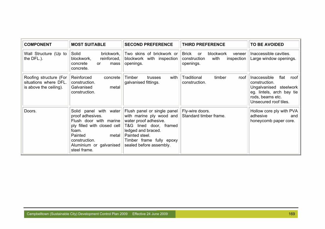
169 Campbelltown (Sustainable City) Development Control Plan 2009 Effective 24 June 2009
TCOMPONENT MOST SUITABLE SECOND PREFERENCE THIRD PREFERENCE TO BE AVOIDED
Wall Structure (Up to the DFL.).
Solid brickwork, blockwork, reinforced, concrete or mass concrete.
Two skins of brickwork or blockwork with inspection openings.
Brick or blockwork veneer construction with inspection openings.
Inaccessible cavities. Large window openings.
Roofing structure (For situations where DFL. is above the ceiling).
Reinforced concrete construction. Galvanised metal construction.
Timber trusses with galvanised fittings.
Traditional timber roof construction.
Inaccessible flat roof construction. Ungalvanised steelwork eg. lintels, arch bay tie rods, beams etc. Unsecured roof tiles.
Doors. Solid panel with water proof adhesives. Flush door with marine ply filled with closed cell foam. Painted metal construction. Aluminium or galvanised steel frame.
Flush panel or single panel with marine ply wood and water proof adhesive. T&G lined door, framed ledged and braced. Painted steel. Timber frame fully epoxy sealed before assembly.
Fly-wire doors. Standard timber frame.
Hollow core ply with PVA adhesive and honeycomb paper core.
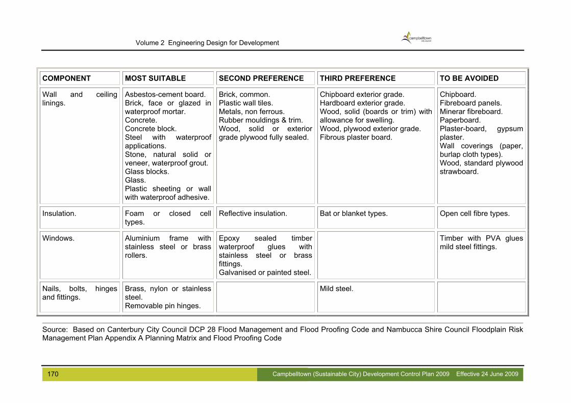
170 Campbelltown (Sustainable City) Development Control Plan 2009 Effective 24 June 2009
Volume 2 Engineering Design for Development
Wall and ceiling linings.
Asbestos-cement board. Brick, face or glazed in waterproof mortar. Concrete. Concrete block. Steel with waterproof applications. Stone, natural solid or veneer, waterproof grout. Glass blocks. Glass. Plastic sheeting or wall with waterproof adhesive.
Brick, common. Plastic wall tiles. Metals, non ferrous. Rubber mouldings & trim. Wood, solid or exterior grade plywood fully sealed.
Chipboard exterior grade. Hardboard exterior grade. Wood, solid (boards or trim) with allowance for swelling. Wood, plywood exterior grade. Fibrous plaster board.
Chipboard. Fibreboard panels. Minerar fibreboard. Paperboard. Plaster-board, gypsum plaster. Wall coverings (paper, burlap cloth types). Wood, standard plywood strawboard.
TCOMPONENT MOST SUITABLE SECOND PREFERENCE THIRD PREFERENCE TO BE AVOIDED
Insulation. Foam or closed cell types.
Reflective insulation. Bat or blanket types. Open cell fibre types.
Windows. Aluminium frame with stainless steel or brass rollers.
Epoxy sealed timber waterproof glues with stainless steel or brass fittings. Galvanised or painted steel.
Timber with PVA glues mild steel fittings.
Nails, bolts, hinges and fittings.
Brass, nylon or stainless steel. Removable pin hinges.
Mild steel.
Source: Based on Canterbury City Council DCP 28 Flood Management and Flood Proofing Code and Nambucca Shire Council Floodplain Risk Management Plan Appendix A Planning Matrix and Flood Proofing Code

171 Campbelltown (Sustainable City) Development Control Plan 2009 Effective 24 June 2009

172 Campbelltown (Sustainable City) Development Control Plan 2009 Effective 24 June 2009
Volume 2 Engineering Design for Development
APPENDIX D
GUIDELINE FOR FLOOD ANALYSIS INVOLVING
LOCAL OVERLAND FLOW

Appendix D Guidelines for Flood Analysis Involving Overland Flow The aim of this guideline is to ensure that a safe and adequate “escape route” is achieved for storm events above that of the pipe system design and to provide a consistent approach for consultants to assess overland flow impacts and pathway systems, but may include drainage easements and natural watercourses.
1. Determine the local catchment from contour plans 2. Calculate the 100 year ARI peak flow from the local catchment 3. If applicable, calculate the minor system flow (i.e. pipe flow). The difference
between the minor system flow and the 100 year ARI peak flow shall be the basis upon which the major system flow path shall be designed
4. Where a minor system operates and sections are prone to blockage by debris, the effects of blockage shall by investigated as follows:
a. Where a failsafe overland flow path exists, 50% blockage of the minor system shall be investigated
b. Where no failsafe overland flow path exists, 100% blockage of the minor system shall be investigated.
5. Calculate the depth of flow: a. Road reserve
i. Cross sections should be taken at the upstream and downstream boundaries of the site.
ii. Intermediate cross sections should also be taken between these boundaries should it be considered more critical or if additional information is required for a large site
iii. Property boundaries are to be considered as vertical walls, on the assumption that all properties will be ultimately filled to the flood level
iv. The appropriate Manning’s roughness coefficients should be adopted.
b. Natural Watercourses / Open Channel i. Determination of drainage paths will require a site survey to be
carried out ii. A sufficient number of sections both within the site and extending
sufficiently upstream and downstream of the site shall be analysed in order to reflect flood behaviour
iii. The hydraulic design shall take into account obstructions to flow such as buildings. Permeable fences may be assumed to not provide an obstruction to flow. Colorbond fences constitute a complete obstruction to flow unless it can be demonstrated that a clear gap has been allowed under the fence
iv. If the 100 year ARI peak flow is not contained within the open channel, then boundaries should be taken as vertical walls at the appropriate alignment
v. A range of Manning’s roughness coefficients should be adopted to reflect the possible maintenance conditions.
6. The more critically calculated depth of flow corresponds to the minimum fill level requirement
7. The minimum floor level control is 500mm above the calculated 100 year ARI flood level
173 Campbelltown (Sustainable City) Development Control Plan 2009 Effective 24 June 2009

Volume 2 Engineering Design for Development
8. Any proposed development of the site will require drainage to be accommodated
in accordance with Chapter 4 of this document 9. No increased impacts on adjoining properties as a result of development of the
subject site will be allowed. Note that this is a guide only. An experienced Hydraulics Engineer with the appropriate NPER registration should be engaged to undertake a flood analysis to manage the 100 year ARI flow and determine the corresponding fill and floor level controls as required. Minimum requirements for submission to Council The consultant must provide the following information to enable Council to assess the study:
1. A written report providing: a. Methodology b. Assumptions c. Calculations d. Conclusions
2. Survey, plan and cross sectional information relevant to the study 3. Copies of all model files created in the assessment of the development 4. Where Council’s preferred software as set out in Section 4.11 is not used, a
comprehensive report detailing all assumptions made and summarising the findings is required.
174 Campbelltown (Sustainable City) Development Control Plan 2009 Effective 24 June 2009

175 Campbelltown (Sustainable City) Development Control Plan 2009 Effective 24 June 2009
176 Campbelltown (Sustainable City) Development Control Plan 2009 Effective 24 June 2009
Volume 2 Engineering Design for Development
APPENDIX E
BANK GUARANTEES AND CASH SECURITY DOCUMENTS
FORMAT & INSTRUCTIONS

Appendix E Bank guarantees and cash security Documents Format & Instructions
SECURITY FOR OUTSTANDING WORKS
INSTRUCTIONS FOR APPLICANTS The following matters must be done by the Applicant before returning a bank guarantee or Cash Deposit. A. BANK GUARANTEE 1. Customer name must be exactly the same as the Applicant name on
the Bank Guarantee. 2. No expiry date is to be shown on the Bank Guarantee. 3. Council will accept guarantees and performance bonds from
accredited banks and organisations with a minimum credit rating of "A" from Standard and Poors or "A2" from Moodys rating agencies.
B. CASH SECURITY 1. Cash deposits can be paid to Council using cash or Bank Cheque.
Personal or Company Cheques will only be accepted for amounts of $10,000 or less.
177 Campbelltown (Sustainable City) Development Control Plan 2009 Effective 24 June 2009

Volume 2 Engineering Design for Development
Example of Bank Guarantee acceptable to Council
Guarantee
General Manager Campbelltown city Council P.O. Box 57 Campbelltown, NSW 2560 Dear Sir In connection with the liability of ________________________________________ (hereinafter called the Applicant) to CAMPBELLTOWN CITY COUNCIL (hereinafter called the Council) for _____________________________________ ____________________________________________________________________________________________________________________________________________________________________________________________________________________________________________________________________ I have to inform you that _____________________________________________ (hereinafter called the Bank) agrees and undertakes to hold itself responsible to Council for the sum of $ _____________________________________________ in aggregate. The Bank will hold itself responsible until notification in writing has been received from Council either that such sum is no longer required or that Council requires payment to be made to it of the whole amount thereof, providing however that the liability of the Bank should not extend beyond the sum of $__________________ in the aggregate. Should you notify the Bank that Council desires payment to be made of the whole or part or parts of the said sum, such payment or payments will from time to time be forthwith made to Council without reference to the abovementioned Applicant and regardless of any claim made on the said sum or any part thereof in any way incidental to the aforesaid liability and notwithstanding any notice given by the aforesaid Applicant or any other person to the Bank not the pay the same. The bank reserves the right to terminate its liability under the within guarantee at any time upon payment of the said sum of $______________________________ to the Council, or such lesser amount as may be required by Council. DATED at _____________________ this __________ day of ___________ 20__ . SIGNED for ____________________________________) By its Attorney__________________________________) In the presence of _______________________________)
178 Campbelltown (Sustainable City) Development Control Plan 2009 Effective 24 June 2009

Continued next page
179 Campbelltown (Sustainable City) Development Control Plan 2009 Effective 24 June 2009
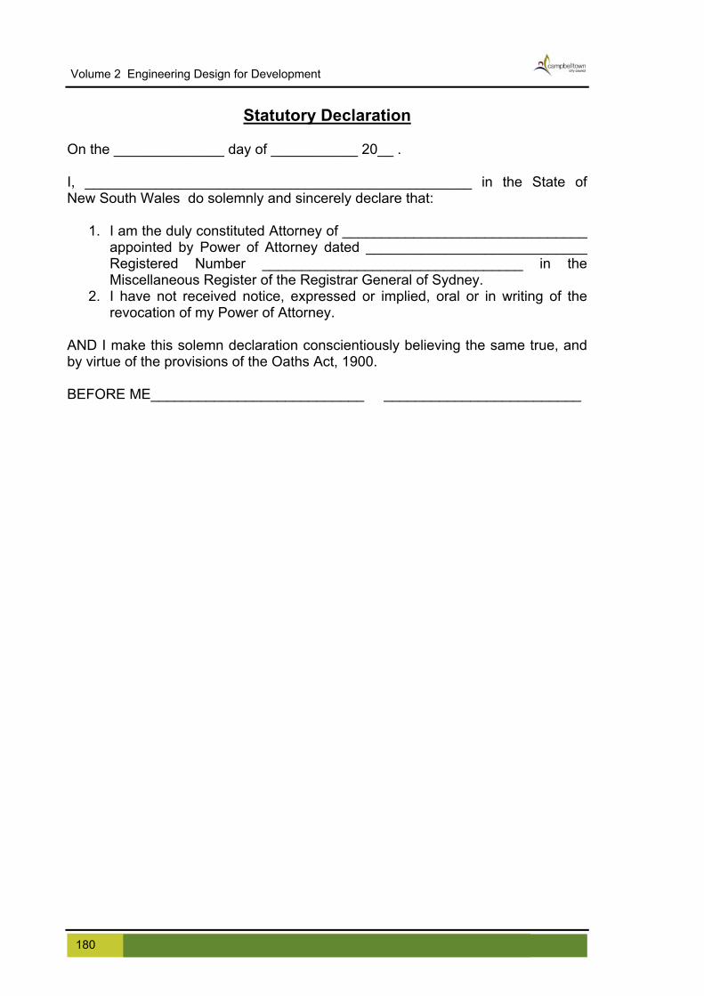
Volume 2 Engineering Design for Development
Statutory Declaration
On the ______________ day of ___________ 20__ . I, _________________________________________________ in the State of New South Wales do solemnly and sincerely declare that:
1. I am the duly constituted Attorney of _______________________________ appointed by Power of Attorney dated ____________________________ Registered Number _________________________________ in the Miscellaneous Register of the Registrar General of Sydney.
2. I have not received notice, expressed or implied, oral or in writing of the revocation of my Power of Attorney.
AND I make this solemn declaration conscientiously believing the same true, and by virtue of the provisions of the Oaths Act, 1900. BEFORE ME___________________________ _________________________
180 Campbelltown (Sustainable City) Development Control Plan 2009 Effective 24 June 2009

181 Campbelltown (Sustainable City) Development Control Plan 2009 Effective 24 June 2009
APPENDIX F
RESTRICTION AS TO USER (RATU)

Volume 2 Engineering Design for Development
Appendix F Restriction as to User (RATU) Terms of restriction that can be incorporated in an instrument under Section 88B of the Conveyancing Act, 1919 as amended. The Conveyancing Act 1919 has been amended by the Property Legislation Amendment (Easements) Act 1995 which commenced on 1 August 1996. Parts of the Acts that affect easement terms are as follows: Access Denied Roads ∆ No means of access to or from the road hereby benefited is to be constructed or allowed to be constructed on any lot hereby burdened, nor will any lot hereby burdened be used or allowed to be used as a means of access to or from the road hereby benefited. The authority empowered to release, vary or modify the above restrictions is Campbelltown City Council. The cost and expense of any such release, variation or modification is to be borne by the person or corporation requesting the same in all respects. Alteration of levels # No alteration is permitted to the finished surface levels attained by site regrading works as shown on Works As Executed Plans approved by Council for the subdivision created by the plan herein firstly mentioned, without the prior written consent of Council. A plan showing full details of any proposed alterations is to be submitted to Council for approval prior to their commencement. Council may also require the submission of a revised Works As Executed Plan certified by a Registered Surveyor. The authority empowered to release, vary or modify the above restrictions is Campbelltown City Council. The cost and expense of any such release, variation or modification is to be borne by the person or corporation requesting the same in all respects.
Floor Level Control * No building is to be erected or remain on the land hereby burdened which has a floor level of any part below a height or heights fixed in writing by Campbelltown City Council (hereinafter called the Council). Applications for the issue of these levels are to be directed to the Council, and the levels issued are to be shown on any Building Application submitted to Council. The Council may also require that no construction above floor level is undertaken prior to certification by a Registered Surveyor that the constructed floor levels comply with Council’s requirements. The authority empowered to release, vary or modify the above restrictions is Campbelltown City Council. The cost and expense of any such release, variation or
182 Campbelltown (Sustainable City) Development Control Plan 2009 Effective 24 June 2009

modification is to be borne by the person or corporation requesting the same in all respects. Filled Lots �> The lots hereby burdened are not to be used for residential purposes UNLESS the Transferor has advised the Transferee that the land has been filled and that no building is to be constructed thereon UNLESS the footings/ foundations have been designer by a qualified Civil/structural Engineer based on geotechnical advice in the form of a report prepared by a laboratory registered with the National Association of Testing Authorities and approved by Campbelltown City Council. The authority empowered to release, vary or modify the above restrictions is Campbelltown City Council. The cost and expense of any such release, variation or modification is to be borne by the person or corporation requesting the same in all respects. Uncontrolled Fill �> The lots hereby burdened are not to be used for residential / industrial purposes UNLESS the Transferor has advised the Transferee that the land has been filled and that part or all of that filling has been identified as uncontrolled fill, and that no building is to be constructed thereon UNLESS the footings/ foundations have been designer by a qualified Civil/structural Engineer based on geotechnical advice in the form of a report prepared by a laboratory registered with the National Association of Testing Authorities and approved by Campbelltown City Council. The authority empowered to release, vary or modify the above restrictions is Campbelltown City Council. The cost and expense of any such release, variation or modification is to be borne by the person or corporation requesting the same in all respects. Garbage Restriction � That the owners or occupiers for the time being of the lots so burdened are not to deposit household refuse containers for the collection by Campbelltown City Council or their appointed contractor in any other location than on the concrete pad provided behind the kerb line in …………….…………..(street name) adjoining. The authority empowered to release, vary or modify the above restrictions is Campbelltown City Council. The cost and expense of any such release, variation or modification is to be borne by the person or corporation requesting the same in all respects.
183 Campbelltown (Sustainable City) Development Control Plan 2009 Effective 24 June 2009

Volume 2 Engineering Design for Development
184 Campbelltown (Sustainable City) Development Control Plan 2009 Effective 24 June 2009

185 Campbelltown (Sustainable City) Development Control Plan 2009 Effective 24 June 2009
Volume 2 Engineering Design for Development
APPENDIX G
EXAMPLE EASEMENT CERTIFICATE

Volume 2 Engineering Design for Development
Appendix G Example Easement Certificate
EXAMPLE CERTIFICATE Council Ref:
General Manager Campbelltown City Council P.O. Box 57 Campbelltown NSW 2560 Dear Sir, Subdivision of Lot D.P. AT Our final Plan of Subdivision bearing the abovementioned description and reference intends to create the following easements over the specified lots. Easement Description Burdened Lots 1. Easement to Drain Water 1506, 1514, to 1519 inclusive, 1.5 metres wide. 1523 to 1526 inclusive. 2. Easement to Drain Water Lot 1527 2.5 metres wide. Drainage pipes and associated structures are laid wholly within the easements to be created by registration of the accompanying linen plan.
Yours faithfully,
Signature
Name of Surveyor (Please Print)
186 Campbelltown (Sustainable City) Development Control Plan 2009 Effective 24 June 2009

187 Campbelltown (Sustainable City) Development Control Plan 2009 Effective 24 June 2009
Volume 2 Engineering Design for Development
APPENDIX H
PLANTING IN DRAINAGE EASEMENTS

Volume 2 Engineering Design for Development
Appendix H Planting in Drainage Easements Council may approve, in writing, the planting of vegetation over drainage easements. Such planting shall be shallow rooted, non hydrophilic native shrubs only. The following list identify plants which are suitable for planting in drainage easements. It should be understood that if Council needs to undertake work within the easement these plants may have to be removed.
Plants Suitable for Planting in Drainage Easements Groundcovers: Native Hardenbergia violaceae Grevillea Bronze Rambler Grevillea Poorinda Royal Mantle Hibbertia scandens Strappy Leaf Plants: Native Lomandra longifolia Lomandra longifolia Katrinus Lomandra Tanika Dianella caerulea Cassa Blue Dianella Breeze Dianella revoluta Little Rev Dianella tasmanica Tas Red Dianella Poa labillardieri cv Eskdale Shrubs: Native Grevillea Honey Gem Grevillea Moonlght Grevillea Pink Surprise Grevillea Robyn Gordon Grevillea Ned Kelly Grevillea Pink Pearl Grevillea hookeriana Grevillea rosmarinifolia Plectranthus argentatus Exotic Groundcovers/climbers Convolvulus maurentenaceus Trachelospermum jasminoidies Gelsemium sempervirons Strappy Leaf Plants: Exotic Liriope muscari "Evergreen Giant" Liriope muscari "Variegata" Liriope muscari Liriope spicata "Siver Dragon" Agapanthus species
188 Campbelltown (Sustainable City) Development Control Plan 2009 Effective 24 June 2009

Volume 2 Engineering Design for Development
Phormium "Bronze Baby" Phormium Elfin Phormium "Platts Black" Phormium tenax Phormiuim" tenax Purpurea" Phormium Yellow Wave Phormium "Moaori Varieties" Clivea hybrida Clivea miniata Clivea miniata [Yellow] Shrubs: Exotic Hebe species Gardenia "Radicans" Gardenia augusta "Florida" Coleonema pulchrum Coleonems "Sunset Gold Spirea bumalda "Red May" Nandina nana Echium fastuosum The list below identifies plants which should not be planted in drainage easements under any circumstances.
Plants Not Suitable for Planting in Drainage Easements Erythrina species (Coral Trees) Eucalyptus species (Large Gum Trees) Jacaranda mimosifolia (Jacaranda) Liquidambar styraciflua (Liquidambar) Araucaria species (Norfolk Island & Bunya Pines) Brachychiton acerifolium (Illawarra Flame Tree) Casuarina species (Casuarinas) Melia azedarach (Australian White Cedar) Pinus species (Pine Trees) Platanus acerifolia (Plane Tree) Schinus molle (Pepper Tree) Ulmus species (Elms) Bougainvillea species (Bougainvilleas) Grevillea robusta (Silky Oak) Ilex species (Hollies) Lagunaria patersonii (Norfolk Island Hibiscus) Magnolia species (Magnolias) Nerium oleander (Oleander) Phoenix canariensis (Canary Island Date Palm) Phyllostachus species (Bamboos) Lophostemon confetus (Brush Box, Tristania) Wisteria species (Wisteria)
189 Campbelltown (Sustainable City) Development Control Plan 2009 Effective 24 June 2009

Volume 2 Engineering Design for Development
190 Campbelltown (Sustainable City) Development Control Plan 2009 Effective 24 June 2009
191 Campbelltown (Sustainable City) Development Control Plan 2009 Effective 24 June 2009
Volume 2 Engineering Design for Development
APPENDIX I
STREET LIGHTING MANAGEMENT GUIDELINES

Volume 2 Engineering Design for Development
Appendix I Street Lighting Management Guidelines
1.0 Objectives The provision of street lighting has a number of objectives:
To provide an appropriate level of illumination along roads, footpaths and walkways
To minimise the total cost for providing street lighting to the community, while meeting set lighting standards
To minimise the effects of glare and light spill into adjacent properties To minimise greenhouse gas emissions by using the most appropriate technology
and techniques 2.0 Lighting Standards 2.1 Local Urban Streets Up until the adoption of the new Street Lighting Standard (AS 1158) in 1997, the standard approach to lighting in older local streets was to provide a lamp on every second street pole. The Australian Standard sets a number of criteria, such as pedestrian/cycle activity, risk of crime and need to enhance prestige, and provides for a number of “P” category standards.
Table I-1 Lighting categories for local roads (extract from AS 1158) Selection Criteria
Description Pedestrian/cycle activity
Risk of crime
Need to enhance prestige
Applicable category
Collector roads Medium Low
Low Low
Medium N/A
P3 P4
Local roads Medium
Low Low
Low Low Low
Medium N/A N/A
P3 P4 P5
New subdivisions and recent lighting upgrades are required to comply with a “P4” lighting level, in accordance with the criteria set in the Australian Standard, and to ensure a consistent lighting environment between collector roads and local roads. Higher lighting levels, such as “P3”, are likely to cause light spill problems for adjacent residents, and would only be supported if specific issues arose that would warrant a higher lighting level.
192 Campbelltown (Sustainable City) Development Control Plan 2009 Effective 24 June 2009

Volume 2 Engineering Design for Development
2.2 Rural Roads There is no specific standard for rural roads, due to the low development density and low pedestrian activity. Rather, “flag” lighting is provided to illuminate intersections, bends and cul de sacs, so that motorists are made aware of specific road hazards by highlighting them with a single street light. 2.3 Traffic Route Lighting The most energy efficient arrangement for traffic route lighting is to use high wattage lamps at a high mounting height, which allows a longer spacing between the lamps. High-pressure sodium lamps are very energy efficient, have a long life, maintain their rated light output for most of their life, and are therefore routinely used for traffic route lighting. These lamps have a characteristic yellow appearance. Most traffic routes in Campbelltown are lit to what is known as “V5” standard, which is the lowest level of lighting permitted under the standard.
Table I-2 Lighting categories for traffic routes (extract from AS 1158)
Description Category
Arterial or main roads in central and regional activity centres of capital and major provincial cities, and other areas with major abutting traffic generators
V1
Freeways and motorways and arterial roads that predominantly carry through traffic V3
Sub arterial roads which connect arterial or main roads to areas of development within a region, or which carry traffic from one part of a region to another part
V5
“V5” is the adopted standard for Campbelltown LGA, as it is consistent with the current standard, provides the lowest cost solution, and minimises problems with light spill into adjacent properties. 2.4 Central Business Districts and High Pedestrian Use Areas As indicated in Section 2.3 above, traffic route lighting generally relies on high wattage sodium lamps, which provide a characteristic yellow light. Many CBD areas, being on major traffic routes, have tended to have standard traffic route lighting installed. However this form of lighting is not suitable in urban centres such as shopping centres, where pedestrians generally prefer a “white” light, which provides a better amenity, and is more natural to the human eye. It is therefore a requirement that town centres, railway station areas and similar high pedestrian use areas use “white” light lamps. This will require the use of metal halide lamps, with consequent higher long term operating costs compared to high-pressure sodium lights. Metal halide lamps provide a natural appearance to people and surroundings, approaching daylight quality colour rendering.
193 Campbelltown (Sustainable City) Development Control Plan 2009 Effective 24 June 2009

194 Campbelltown (Sustainable City) Development Control Plan 2009 Effective 24 June 2009
Volume 2 Engineering Design for Development
Table I-3 Lighting categories for public activity areas (extract from AS 1158) Selection Criteria
Description Night time
vehicle movements
Risk of crime
Need to enhance prestige
Applicable category
Areas primarily for pedestrian use, such as shopping precincts, malls, town centres, with generally only pedestrian movements
N/A Medium
Low
High Medium
Low
High Medium
N/A
P6 P7 P8
Transport terminals and interchanges, with mixed pedestrian and vehicle movements
High Medium
Low
High Medium
Low
High Medium
N/A
P6 P7 P8
With regard to the lighting category to be used, the standard provides guidance as indicated in the above table. It is required that “P7” is the minimum standard for these situations, in view of the traffic issues, the specific perceptions about crime in these areas, and to provide an opportunity to enhance the attractiveness of these areas. 2.5 Walkways, pathways and cycleways The lighting categories identified in the Australian Standard are:
Table I-4 Lighting Categories Selection Criteria
Description Pedestrian/cycle activity
Risk of crime
Need to enhance prestige
Applicable category
Pedestrian or cycle orientated pathways – footpaths, walkways, lanes, park paths, cycleways
N/a High
Medium Low
High Medium
Low Low
N/A High
Medium N/A
P1 P2 P3 P4
Generally P4 is to be adopted in most situations, with P3 sometimes being used depending on circumstance. However, lighting levels of P3 and above are likely to cause significant light spill and glare to adjacent residents, and for this reason higher P categories are avoided where residential property is located immediately adjacent to walkways. It is intended that P4 continue to be the minimum lighting category for these facilities, with higher categories used only where the risk of light spill is low. Cycleways in parks, and the lighting of parks generally, needs to be considered having regard to the Police Service’s Safer by Design principles. Isolated lighting tends to increase the perception of poor safety, as the adjacent unlit areas are seen as being more dark in comparison to the lit areas. Therefore any lighting in parks needs to be considered on its merits, rather than setting a specific standard.

195 Campbelltown (Sustainable City) Development Control Plan 2009 Effective 24 June 2009
Volume 2 Engineering Design for Development
2.6 Outdoor Carparks The Standard provides for only two categories of lighting for carparks:
P11 for parking spaces, aisles and roadways P12 for designated disabled parking bays
All new carparks are required to meet these standards. 2.7 Pedestrian Crossings The standard for lighting of pedestrian crossings is based on the assumption of category “V5” lighting on the approaches. Clearly this is not the case in the majority of cases in the City, as most crossings are located on local roads with “P” category lighting. In order to provide a rational approach to the provision of lighting, pedestrian crossings have been divided into two categories for assessment:
Pedestrian crossings with significant night time pedestrian activity, such as near shopping centres and train stations will require full compliance with the relevant standard, including upgrading of the approaches in accordance with the Australian Standard. It is noted that this results in a very bright environment, will result in significant light spill into adjacent properties.
Pedestrian crossings with limited night-time pedestrian traffic. In these situations specific lighting at the crossing will consist of dual floodlights to illuminate the actual crossing only. This will minimise the adverse impacts on adjacent residents, and minimise costs to the community, where there is no specific night-time warrant for lighting.
3.0 Energy Efficient Lighting A key goal is to maximise the use of energy efficient lighting, to minimise greenhouse gas emissions and to minimise the cost of lighting to the community, while achieving an appropriate standard of lighting. All new subdivisions and upgrades of existing infrastructure are to use 2X14w T5 fluorescent technology luminaries for local road P4 category situations.

196 Campbelltown (Sustainable City) Development Control Plan 2009 Effective 24 June 2009
Volume 2 Engineering Design for Development

197 Campbelltown (Sustainable City) Development Control Plan 2009 Effective 24 June 2009
Volume 2 Engineering Design for Development
APPENDIX J
DOCUMENT HISTORY

198 Campbelltown (Sustainable City) Development Control Plan 2009 Effective 24 June 2009
Volume 2 Engineering Design for Development
Appendix J Document History This document was originally issued as Council’s Engineering Design Guide for Development in October 2004. The decision was made to incorporate this document as Volume 2 of Council’s Campbelltown (Sustainable City) Development Control Plan 2007. This section documents changes that have been made to the document since it’s original issue.
Change Date The Engineering Design Guide for Development was originally issued in October 2004 as a technical guidance document.
October 2004
Incorporation as Volume 2 of Draft Campbelltown (Sustainable City) Development Control Plan
May 2007
Removed registration page May 2007 Minor changes to objectives in Foreword May 2007 Addition of section 3.6 (xi) on Recycled Materials May 2007
Revised SD R13 May 2007 Revised SD NTD05 May 2007 2.12 and checklist - Cul-de-sac minimum radius from 8.5m to 12.5m to account for garbage truck movement.
May 2007
Changes to standard drawings – details indicated on any changed drawings as amendments.
May 2007
Inclusion of requirements to assess public area construction works using CHAIR
May 2007
Discussion of critical and vulnerable infrastructure and evacuation routes added to section 4.5
May 2007
Table 4.1 wording amended May 2007 Table 4.2 amended with removal of ranges of values May 2007 Table 4.4 amended with removal of ranges of values May 2007 Table 4.10 amended with removal of ranges of values May 2007 Section 4.11 amended with Council’s preferred computer models May 2007 Section 4.14.8 details regarding industrial connections added May 2007 Figure 4.11 amended May 2007 Section 4.14.9 new requirements added for industrial lots May 2007 Section 5.3 moisture content quantified May 2007 Consideration of salinity added to the checklist May 2007 Section 5.3 lot filling compaction changes to 98% May 2007 Section 5.7 paragraphs deleted as now covered in Volume 1 May 2007 Section 5.8 resources expanded May 2007 Section 5.13 Emergency Vehicle Access added May 2007 Inclusion of Appendix detailing planting over drainage easements May 2007 Inclusion of 90 minute storm information in Appendix B May 2007 Inclusion of Tuflow modelling requirements in Appendix B May 2007 All standard drawings have been reviewed. Where any changes have been made these are identified on the drawing. Table in Appendix J reflects changes
May 2007
Recent changes to state government departments reflected in references throughout the document
May 2007
Minor spelling, grammar and editorial errors May 2007

199 Campbelltown (Sustainable City) Development Control Plan 2009 Effective 24 June 2009
Volume 2 Engineering Design for Development
Change Date Definition of Qualified Surveyor added to Glossary March 2009 Reference to DCP amended to be current throughout March 2009 References to state government departments updated throughout March 2009 Section on Road Occupancy added to Section 1.4 March 2009 Changes to Section 1.16 Work as Executed Plans March 2009 Section 3.6 changes to AC thickness requirements March 2009 Section 3.7 changes to pavement surfacing requirements March 2009 Changes to Section 3.28 Traffic Control for Works in Public Roads March 2009 Reference documents in section 4.1 updated March 2009 Table 4.2 Percentage Impervious amended March 2009 Table 4.3 Pit Blockage Factors amended March 2009 References in Section 4.15 updated March 2009 Section 4.17 inclusion of a section regarding draining over Council land
March 2009
Table 4.18 Easement Widths minor amendments March 2009 Figure 4.11 Zone of Influence amended March 2009 Figure 4.12 Velocity Depth relationships clarified March 2009 Section 4.25 added requiring assessment of the impact of climate change on stormwater systems for significant developments
March 2009
Section 5.3 Reference to fill extended to cut and fill March 2009 Section 5.3 minor wording changes March 2009 References in Section 5.8 updated March 2009 March 2009 References to policies which have been repealed removed (various)
March 2009
Appendix A change to wording re vertical road alignment March 2009 Appendix A amended to include climate change considerations March 2009 Appendix B minor changes to PERN values for use in Rafts Model March 2009 Changes to Standard Drawings as noted in Appendix J March 2009 Appendix J and K swapped in order March 2009

200 Campbelltown (Sustainable City) Development Control Plan 2009 Effective 24 June 2009
Volume 2 Engineering Design for Development

201 Campbelltown (Sustainable City) Development Control Plan 2009 Effective 24 June 2009
Volume 2 Engineering Design for Development
APPENDIX K
STANDARD DRAWINGS

202 Campbelltown (Sustainable City) Development Control Plan 2009 Effective 24 June 2009
Volume 2 Engineering Design for Development
Appendix K Standard Drawings The title on all Standard Drawings was amended to remove reference to the year of the DCP revision. All amendment history is noted in the amendment boxes on the Standard Drawings. Standard Drawing Number
Number of Sheets
Title Any changes from 2007 Version
Notes SD-NT01 1 Notes – General NO SD-NT02 1 Notes – Concrete NO SD-NT03 1 Notes – Earthworks NO SD-NT04 1 Notes – Steelwork and Steel Reinforcement NO SD-NT05 1 Notes – Special Conditions NO SD-NT06 4 Notes – Product Specifications NO SD-NT07 1 Notes – Sediment and Erosion Control NO
Roads
SD-R01 1 Vertical Curves NO SD-R02 1 Cul-de-sac Standard NO SD-R03 1 Kerb Return Layout and Design Details NO SD-R04 1 Kerbs and Gutters NO SD-R05 1 Sub-soil Drainage NO SD-R06 1 Kerb Weephole and Kerb Adaptor NO SD-R07 4 Kerb Ramps NO SD-R08 2 Residential Vehicle Crossing YES SD-R09 2 Medium Density Vehicle Crossing YES SD-R10 2 Commercial and Industrial Vehicle Crossing YES SD-R11 1 Footpath YES SD-R12 1 Bicycle Path NO SD-R13 1 Low Mountable Island NO SD-R14 1 T-intersection Treatment NO SD-R15 1 Roundabouts YES SD-R16 1 Parking Modification to Provide Disabled
Persons Parking NO
SD-R17 1 Zig zag Pavement Markers NO SD-R18 1 Street Sign NO SD-R19 1 Supplementary Road Name Signposting for
Roundabouts NO
SD-R20 1 Log Vehicle Barrier YES SD-R21 1 Cycle path Holding Rail NO SD-R22 1 Laneway Baulk NO

203 Campbelltown (Sustainable City) Development Control Plan 2009 Effective 24 June 2009
Volume 2 Engineering Design for Development
Standard Drawing Number
Number of Sheets
Title Any changes from 2007 Version
SD-R23 1 Pathway Baulks NO SD-R24 1 Wire Rope Barrier NO
Stormwater
SD-S01 1 Trash Rack Warning Sign NO SD-S02 1 Pipe Flood Warning Sign NO SD-S03 1 Floodway Warning Sign NO SD-S04 1 Geo-composite Drain NO SD-S05 1 Connection to Main Drain NO SD-S06 1 Grated Gully Pit with Extended Kerb Inlet Pit NO SD-S07 1 Kerb Median Inlet Pit NO SD-S08 1 Surcharge Pit NO SD-S09 1 Step Irons NO SD-S10 1 Minor Drainage Connections NO SD-S11 1 Surface Inlet and Letterbox Pit NO SD-S12 2 Heavy Duty Junction Pit NO SD-S13 2 Outlet Details Grass Lined Channel/Creel NO SD-S14 1 Reinforced Turf Detail NO SD-S15 1 Pyramid Grate NEW SD-S16 1 No climbing warning sign NEW SD-S17 1 No planting warning sign NEW
Miscellaneous
SD-M01 1 Erosion and Sediment Control Plan NO SD-M02 1 Stockpiles NO SD-M03 1 Earth Bank (low flow) NO SD-M04 1 Straw Bale Filter NO SD-M05 1 Sediment Fence NO SD-M06 1 Mesh and Gravel Inlet Filter NO SD-M07 1 Geotextile Inlet Filter NO SD-M08 1 Kerbside Turf Strip NO SD-M09 1 Stabilised Site Access NO