Volume 1 (Chapters 1-3) crane operator and maintain
104
CARGO DECK CRANE VOLUME 1 INSTRUCTION / MAINTENANCE TYPE CBW 45(40)32/20(24,4)27,5 ST ORDER − NO. 162 211 Subject to alteration! 1 st Edition: 03.05.2002 /ab LIEBHERR−WERK−NENZING GMBH, P.O.Box 10, A−6710 Nenzing / Austria / Europe Phone (05525) 606−0, Telex 052141 lwn a, Telefax (05525) 606−200
-
Upload
poojitha-dilhan -
Category
Documents
-
view
446 -
download
21
description
This DOCUMENTATION has been prepared to allow the safe operation of the LIEBHERR crane while utilizing the crane’s full range of operating possibilities. In addition,the manual emphasizes the daily routine maintenance and informs the operator of theoperating principles of important assemblies and systems.
Transcript of Volume 1 (Chapters 1-3) crane operator and maintain

CARGO DECK CRANE
VOLUME 1
INSTRUCTION / MAINTENANCE
TYPE
CBW 45(40)32/20(24,4)27,5 ST
ORDER − NO.
162 211
Subject to alteration!1st Edition: 03.05.2002 /ab
LIEBHERR−WERK−NENZING GMBH, P.O.Box 10, A−6710 Nenzing / Austria / EuropePhone (05525) 606−0, Telex 052141 lwn a, Telefax (05525) 606−200

F O R E W O R D
This DOCUMENTATION has been prepared to allow the safe operation of the LIEB�HERR crane while utilizing the crane’s full range of operating possibilities. In addition,the manual emphasizes the daily routine maintenance and informs the operator of theoperating principles of important assemblies and systems.
VOLUME 1 − INSTRUCTION / MAINTENANCE MANUAL
VOLUME 2 − TECHNICAL INFORMATION
VOLUME 3 − SPARE PARTS LIST
The DOCUMENTATION is prepared for extended service−, repair− and maintenancework as well as ordering spare parts. This manual shall be used by trained Service−per�sonnel only.
This LIEBHERR crane shall be operated and serviced by from LIEBHERR−WERK NEN�ZING trained or authorized personnel only.
The procedures described in the DOCUMENTATION and general safety precautionsshall be observed at all times.
NON−OBSERVANCE OF THESE RULES CAN RESULTIN PERSONAL INJURY AND STRUCTURAL DAMAGE.
Special attention shall be given to the safety devices built−in to the crane. They shallbe tested at regular intervals for good condition and proper operation. Crane operationis prohibited if the safety devices are not working properly.
"S A F E T Y A L W A Y S C O M E S F I R S T"
must be the way of thinking and behaviour before, during and after crane operation.
If you receive any further information for the crane, such as technical modifications orchanges concerning operation, maintenance, or spare parts − please attach them toprovided volumes.

PREFACE
−1.1− 1043
INDEX − VOLUME 1
1. PREFACE 1.5. . . . . . . . . . . . . . . . . . . . . . . . . . . . . . . . . . . . . . . . . . . . . . . . . . . . .
1.1. TO THE OWNER 1.5. . . . . . . . . . . . . . . . . . . . . . . . . . . . . . . . . . . . . . . . . . . . . . . 1.2. GENERAL INFORMATION 1.6. . . . . . . . . . . . . . . . . . . . . . . . . . . . . . . . . . . . . . . 1.3. CRANE APPLICATION AND OPERATION 1.6. . . . . . . . . . . . . . . . . . . . . . . . . 1.4. CONVERSION TABLE 1.8. . . . . . . . . . . . . . . . . . . . . . . . . . . . . . . . . . . . . . . . . . 1.5. STANDARD HAND SIGNALS FOR CONTROLLING CRANE
OPERATIONS 1.9. . . . . . . . . . . . . . . . . . . . . . . . . . . . . . . . . . . . . . . . . . . . . . . . . 1.6. GENERAL HINTS AND ADVISE FOR CRANE OPERATION 1.10. . . . . . . . . . 1.7. EXPLANATION OF SAFETY SIGNS 1.15. . . . . . . . . . . . . . . . . . . . . . . . . . . . . . . 1.8. LIEBHERR WORLD−WIDE SERVICE ORGANIZATION 1.19. . . . . . . . . . . . . .
2. GENERAL DESCRIPTION 2.3. . . . . . . . . . . . . . . . . . . . . . . . . . . . . . . . . . . . . .
2.1. ARRANGEMENT OF THE MAIN PARTS OF THE CRANE 2.3. . . . . . . . . . . . 2.2. TECHNICAL DESCRIPTION OF THE CRANE 2.8. . . . . . . . . . . . . . . . . . . . . . 2.3. LAYOUT OF THE OPERATOR’S CABIN 2.12. . . . . . . . . . . . . . . . . . . . . . . . . . . 2.4. CONTROLS ON THE SWITCH CABINET X1 2.17. . . . . . . . . . . . . . . . . . . . . . . 2.5. PREPARATIONS FOR CRANE OPERATION 2.19. . . . . . . . . . . . . . . . . . . . . . . 2.6. CRANE OPERATION 2.20. . . . . . . . . . . . . . . . . . . . . . . . . . . . . . . . . . . . . . . . . . .
3. MAINTENANCE 3.3. . . . . . . . . . . . . . . . . . . . . . . . . . . . . . . . . . . . . . . . . . . . . . .
3.1. GENERAL 3.3. . . . . . . . . . . . . . . . . . . . . . . . . . . . . . . . . . . . . . . . . . . . . . . . . . . . . 3.2. SPECIAL SAFETY REGULATIONS 3.4. . . . . . . . . . . . . . . . . . . . . . . . . . . . . . . . 3.3. MAINTENANCE OF HYDRAULIC SYSTEM 3.9. . . . . . . . . . . . . . . . . . . . . . . . 3.4. PRESSURE ACCUMULATORS 3.13. . . . . . . . . . . . . . . . . . . . . . . . . . . . . . . . . . . 3.5. LIEBHERR CONDITION MONITORING 3.14. . . . . . . . . . . . . . . . . . . . . . . . . . . 3.6. GEARBOXES 3.19. . . . . . . . . . . . . . . . . . . . . . . . . . . . . . . . . . . . . . . . . . . . . . . . . . 3.7. MULTIPLE DISC BRAKES 3.22. . . . . . . . . . . . . . . . . . . . . . . . . . . . . . . . . . . . . . . 3.8. INSTRUCTIONS FOR USE OF CRANE ROPES 3.23. . . . . . . . . . . . . . . . . . . . 3.9. REPLACEMENT OF ROPES 3.27. . . . . . . . . . . . . . . . . . . . . . . . . . . . . . . . . . . . . 3.10. ROPE PULLEYS 3.29. . . . . . . . . . . . . . . . . . . . . . . . . . . . . . . . . . . . . . . . . . . . . . . 3.11. ROLLER SLEWING RING 3.32. . . . . . . . . . . . . . . . . . . . . . . . . . . . . . . . . . . . . . . 3.12. ELECTRICAL SYSTEM 3.33. . . . . . . . . . . . . . . . . . . . . . . . . . . . . . . . . . . . . . . . . . 3.13. MAINTENANCE INSTRUCTIONS FOR SLIP RING UNIT 3.34. . . . . . . . . . . . . 3.14. LUBRICATION AND GREASING DIAGRAM 3.35. . . . . . . . . . . . . . . . . . . . . . . . 3.15. MAINTENANCE LISTS 3.37. . . . . . . . . . . . . . . . . . . . . . . . . . . . . . . . . . . . . . . . . 3.16. SERVICE SPARE−PARTS AND STANDARD TOOLS 3.53. . . . . . . . . . . . . . . .
TABLE OF LUBRICANTS

PREFACE
−1.2− 1043
1043

PREFACE
−1.3− 1043
INDEX
1. PREFACE 1.5. . . . . . . . . . . . . . . . . . . . . . . . . . . . . . . . . . . . . . . . . . . . . . . . . . . . .
1.1. TO THE OWNER 1.5. . . . . . . . . . . . . . . . . . . . . . . . . . . . . . . . . . . . . . . . . . . . . . .
1.2. GENERAL INFORMATION 1.6. . . . . . . . . . . . . . . . . . . . . . . . . . . . . . . . . . . . . . .
1.2.1. CRANE SERIAL NUMBER 1.6. . . . . . . . . . . . . . . . . . . . . . . . . . . . . . . . . . . . . . . . . . . . . . . . . . . 1.2.2. SPARE PARTS / REPAIRS 1.6. . . . . . . . . . . . . . . . . . . . . . . . . . . . . . . . . . . . . . . . . . . . . . . . . . . . 1.2.3. PRESERVATION 1.6. . . . . . . . . . . . . . . . . . . . . . . . . . . . . . . . . . . . . . . . . . . . . . . . . . . . . . . . . . . . 1.2.4. WELDING OPERATIONS 1.6. . . . . . . . . . . . . . . . . . . . . . . . . . . . . . . . . . . . . . . . . . . . . . . . . . . .
1.3. CRANE APPLICATION AND OPERATION 1.6. . . . . . . . . . . . . . . . . . . . . . . . .
1.3.1. GENERAL 1.6. . . . . . . . . . . . . . . . . . . . . . . . . . . . . . . . . . . . . . . . . . . . . . . . . . . . . . . . . . . . . . . . . 1.3.2. APPLICATION 1.6. . . . . . . . . . . . . . . . . . . . . . . . . . . . . . . . . . . . . . . . . . . . . . . . . . . . . . . . . . . . . . 1.3.3. USE OF THE CARGO DECK CRANE 1.7. . . . . . . . . . . . . . . . . . . . . . . . . . . . . . . . . . . . . . . . . .
1.4. CONVERSION TABLE 1.8. . . . . . . . . . . . . . . . . . . . . . . . . . . . . . . . . . . . . . . . . .
1.5. STANDARD HAND SIGNALS FOR CONTROLLING CRANE OPERATIONS 1.9. . . . . . . . . . . . . . . . . . . . . . . . . . . . . . . . . . . . . . . . . . . . . . . . .
1.6. GENERAL HINTS AND ADVISE FOR CRANE OPERATION 1.10. . . . . . . . . .
1.6.1. GENERAL SAFETY RULES 1.11. . . . . . . . . . . . . . . . . . . . . . . . . . . . . . . . . . . . . . . . . . . . . . . . . . .
1.7. EXPLANATION OF SAFETY SIGNS 1.15. . . . . . . . . . . . . . . . . . . . . . . . . . . . . . .
1.7.1. PROHIBITION SIGNS 1.15. . . . . . . . . . . . . . . . . . . . . . . . . . . . . . . . . . . . . . . . . . . . . . . . . . . . . . . 1.7.2. WARNING SIGNS 1.15. . . . . . . . . . . . . . . . . . . . . . . . . . . . . . . . . . . . . . . . . . . . . . . . . . . . . . . . . . . 1.7.3. MANDATORY SIGNS 1.16. . . . . . . . . . . . . . . . . . . . . . . . . . . . . . . . . . . . . . . . . . . . . . . . . . . . . . . . 1.7.4. RESCUE SIGNS 1.17. . . . . . . . . . . . . . . . . . . . . . . . . . . . . . . . . . . . . . . . . . . . . . . . . . . . . . . . . . . .
1.8. LIEBHERR WORLD−WIDE SERVICE ORGANIZATION 1.19. . . . . . . . . . . . . .

PREFACE
−1.4− 1043

PREFACE
−1.5− 1043
1. PREFACE
1.1. TO THE OWNER
Any questions concerning to the care and upkeep of this crane which have not been covered in thisbook should be directed to your nearest LIEBHERR SERVICE STATION.
LIEBHERR reserves the right to make alterations or modifications to this equipment at any time, which intheir opinion may improve the performance or efficiency of the crane.
�DANGER","WARNING", "ATTENTION", "IMPORTANT" and "NOTES" are used throughout thismanual to emphasize critical instructions. In this manual these special instructions are used as follows:
DANGER !Denotes an extreme intrinsic hazard, which could result in a high pro�ability of death or serious injury, if proper precautions are not taken.
WARNING !Denotes a hazard, which could result in injury or death, if proper pre�cautions are not taken.
ATTENTION !Denotes a reminder of safety pratices or directs attention to unsafepractices, if proper precautions are not taken.
. IMPORTANT !
Denotes IMPORTANT operation and maintenance procedures, which could result in damageor destruction of the machine or in any of its components, if not observed.
. NOTE !
NOTE describes operation and maintenance procedures, which should be followed to keepyour CRANE operational and insure long machine life and to facilitate certain procedures.
The safety rules included in this manual represents a minimum set of standards for safe crane opera�tion. Every operator should be familar with and follow these rules at all times. Written rules, however,cannot cover all situations which might occur on the job.

PREFACE
−1.6− 1043
1.2. GENERAL INFORMATION
1.2.1. CRANE SERIAL NUMBER
For easy identification each crane is marked with a serial number. This serial number is punched into aplate fixed to the base frame of the slewing column.
All correspondence with Liebherr or one of our branch offices should include the respective serial num�ber of the crane.
1.2.2. SPARE PARTS / REPAIRS
In case crane components or service products have to be replaced, resp. added, only original equip�ment from the manufacturer and service products which are identical (design and function ) to the origi�nal exchanged parts resp. products must be used.
If spare parts or service products other than those authorized by the original equipment manufacturer,LIEBHERR cannot be hold responsible for any malfunction or damage to persons or property.
Repairs or modifications on the crane software package are only allowed to be made by service engi�neers from LIEBHERR or LIEBHERR authorized personnel.
1.2.3. PRESERVATION
The crane has to be preserved if not in operation for more than 3 months.
Preservation instructions are obtainable through our service department.
1.2.4. WELDING OPERATIONS
Welding operations on the crane to be executed by qualified welders only with approved welding materi�al and welding procedures, fully in accordance with the requirements of the relevant classification soci�ety.
1.3. CRANE APPLICATION AND OPERATION
1.3.1. GENERAL
This is probably the most important area relative to safety since it involves the greatest frequency of ex�posure to danger. The operator should be of sound mind and body and be able to understand and ap�ply established operating rules. He should be able to exercise good judgment in dealing with the manysituations which cannot be anticipated and covered herein.
Since the manufacturer has no direct control over the crane application and operation, the user isfully responsible for good safety practice.
1.3.2. APPLICATION
In general, established operating safety rules should be observed when performing operating functions.Operating safety rules are found in codes of the following organization:
−DOE (Department of Energy)
−ILO (International Labour Organization)
and in the Occupational Safety and Health Act, as well as in Local or National Codes.
It is obvious that written rules cannot cover all situations that might be encountered on the job. To meetsuch unexpected situations the operator must be able to supplement the rules mentioned above withhis own ones based on good judgment.

DANGER !Observe without fail the capacities for the individual operating situations. You will find these in the Technical Data as well as in the capacity charts inthe Operation Manual.
PREFACE
−1.7− 1043
1.3.3. USE OF THE CARGO DECK CRANE
Intended Operation
The LIEBHERR CARGO DECK CRANE is designed only for crane operation and only lifting applianceswhich have been approved by the crane manufacturer are to be used. The crane may only be used forloads which lie within the limits of the appropriate load curve.
It is to be assumed that the exterior conditions for the working range of the crane do meet the workingrequirements, so that the technical details stated in the section ‘Technical Data‘ regarding angles, in�clines, etc. can be maintained without risk.
When working, the crane is designed for hook operation. This also applies when the correspondinghoist accessories used by the customer meet the regulations of the crane type. In case of any doubts,this should be explicitly clarified.
Use of professional personnel
Operation, service, maintenance and repairs may only be carried out by specially trained personnel. Itmust be ensured that the trained personnel who are engaged do not only dispose of the correspondingspecialized knowledge, but in addition also know and use all questions relating to safety and preventionof accident regulations.
Environmental Conditions
For the safe operation of the crane it is absolutely necessary to ensure that the environmental condi�tions, under which the machine will be operating, are according to regulations.
Other Foreseeable Misuses like
−offlead/Sidelead or dragging loads
−transporting of people or personnel
−operating loads outwith the prescribed limits
are strictly forbidden !

PREFACE
−1.8− 1043
1.4. CONVERSION TABLE
Conversion factors for SI units : The current edition of the rules are in dual units presented with theMKS units first followed by the U.S. Customary units in parentheses. A third system of units now beingused internationally is the system Internation d’Unites (SI). For the convenience of the purchasers of thisbook who use SI units, the following conversion table has been included. This table only provides con�version factors for those U.S. Customary units and MKS units that differ from SI units, that are used inthe rules and guides of the American Bureau of Shipping. Proper use of significant figures and round�ing−off techniques should be given due consideration when using the conversion table.
Quantity U.S. Customary Multiply by To obtain SI unitsor MKS Unit
Area ft2 9.290 304 (10−2)* m2
in2 6.451 600 (102)* mm2
Bending, Torque lb−in 1.129 848 (10−1) Nmkg−m 9.806 650* Nm
Density lb/in3 2.767 990 (104) kg/m3
Electrical ft−lb 1.355 818 Jin−lb 1.129 848 (10−1) Jkcal 4.186 800 (103)* Jkg−m 9.806 650* J
Force lb 4.448 222 Nton (long) 9.964 017 (103) Nkg 9.806 650* Nton (metric) 9.806 650 (103)* N
Length fathom 1.828 800 mft 3.048 (10−1)* min 2.540 (101)* mm
Mass lb 4.535 924 (10−1) kgton (long) 1.016 047 (103) kgton (metric) 1.000 (103) kg
Plan angle degree p/180 rad
Power hp 7.456 999 (102) Whp (metric) 7.354 99 (102) W
Pressure, Stress psi 6.894 757 (103) N/m2 (or Pa)6.894 757 (10−3) N/mm2
6894 757 (10−2) bar (or 105N/m2)ton (long) in2 1.544 426 (107) N/m2 (or Pa)
1.544 426 (101) N/mm2
kg/cm2 9.806 650 (104)* N/m2 (or Pa)9.806 650 (10−1) bar (or 103 N/m2)
kg/mm2 9.806 650 (106)* N/m2 (or Pa)
Temperature °F (°F − 32) / 1.8* °CVelocity knot (kn) 0.514 444 m/sec.Volume ft3 2.831 685(10−2) m3
gallon (liquid) 3.785 412 (10−3) m3
3.785 412 Iin3 1.638 706 (104) mm3
* Exact value ABS January 1980

HOIST LOWER USE MAIN HOIST
USE WHIP LINE RAISE JIB LOWER JIB
MOVE SLOWLYLOWER THE LOADRAISE JIB AND LOWER JIB AND
RAISE THE LOAD
SWING STOP EMERGENCY STOP
TRAVEL STOP ALLMOVEMENTS
PREFACE
−1.9− 1043
1.5. STANDARD HAND SIGNALS FOR CONTROLLING CRANE OPERATIONS
PREFACE
−1.10− 1043
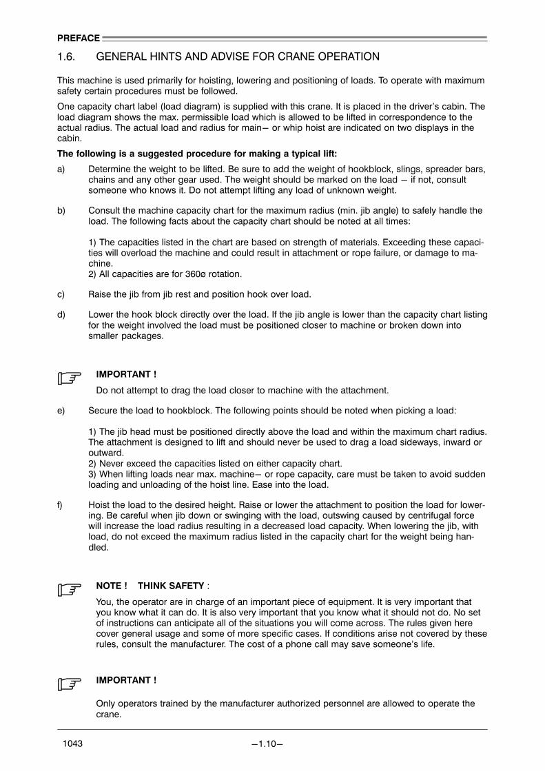
1.6. GENERAL HINTS AND ADVISE FOR CRANE OPERATION
This machine is used primarily for hoisting, lowering and positioning of loads. To operate with maximumsafety certain procedures must be followed.
One capacity chart label (load diagram) is supplied with this crane. It is placed in the driver’s cabin. Theload diagram shows the max. permissible load which is allowed to be lifted in correspondence to theactual radius. The actual load and radius for main− or whip hoist are indicated on two displays in thecabin.
The following is a suggested procedure for making a typical lift:
a) Determine the weight to be lifted. Be sure to add the weight of hookblock, slings, spreader bars,chains and any other gear used. The weight should be marked on the load − if not, consultsomeone who knows it. Do not attempt lifting any load of unknown weight.
b) Consult the machine capacity chart for the maximum radius (min. jib angle) to safely handle theload. The following facts about the capacity chart should be noted at all times:
1) The capacities listed in the chart are based on strength of materials. Exceeding these capaci�ties will overload the machine and could result in attachment or rope failure, or damage to ma�chine.2) All capacities are for 360ø rotation.
c) Raise the jib from jib rest and position hook over load.
d) Lower the hook block directly over the load. If the jib angle is lower than the capacity chart listingfor the weight involved the load must be positioned closer to machine or broken down intosmaller packages.
. IMPORTANT !
Do not attempt to drag the load closer to machine with the attachment.
e) Secure the load to hookblock. The following points should be noted when picking a load:
1) The jib head must be positioned directly above the load and within the maximum chart radius.The attachment is designed to lift and should never be used to drag a load sideways, inward oroutward. 2) Never exceed the capacities listed on either capacity chart.3) When lifting loads near max. machine− or rope capacity, care must be taken to avoid suddenloading and unloading of the hoist line. Ease into the load.
f) Hoist the load to the desired height. Raise or lower the attachment to position the load for lower�ing. Be careful when jib down or swinging with the load, outswing caused by centrifugal forcewill increase the load radius resulting in a decreased load capacity. When lowering the jib, withload, do not exceed the maximum radius listed in the capacity chart for the weight being han�dled.
. NOTE ! THINK SAFETY :
You, the operator are in charge of an important piece of equipment. It is very important thatyou know what it can do. It is also very important that you know what it should not do. No setof instructions can anticipate all of the situations you will come across. The rules given herecover general usage and some of more specific cases. If conditions arise not covered by theserules, consult the manufacturer. The cost of a phone call may save someone’s life.
. IMPORTANT !
Only operators trained by the manufacturer authorized personnel are allowed to operate thecrane.

PREFACE
−1.11− 1043
1.6.1. GENERAL SAFETY RULES
1) Read this operators manual and heed it. The manual contains valuable information.
2) Whenever an operator leaves the crane for any reason, the following must be done:a) Lower the load to firm supporting surface.b) Shut down engine.c) Never depend upon the winch brake to suspend a load, unless the operator is at the controlsand ready to handle the load. Brake slippage, vandals, mechanical malfunctions could causethe load to drop if left in the air unattended.
3) The operator must not eat, read, or otherwise given his attention while operating the crane. Re�member, operating is a full time job.
4) Don’t allow crane loads to pass over people, or endanger their safety. Remove all loose objects.All non−operating personnel should leave the immediate area when the crane is operating.
5) Be sure your work area is clear. Make sure you have proper clearance for crane, jib and load.Don’t swing, hoist or lower the load, raise or lower jib without first making sure no one is in theway. If your vision is obscured, locate a signal man so you can see him and he can see all areasyou can’t. Follow his signals. Be sure you and the signal man understand each others signals.
6) Inspect the crane daily. Don’t operate a damaged or poorly maintained crane. Pay particularattention to the attachment and wire ropes. If a component is worn or damaged, replace it be�fore operating. Remember, parts are cheaper than people. OSHA (Occupational Safety andHealth Act) regulations state "a through inspection of all ropes shall be made once a month anda full, written, dated and signed report of rope condition kept on file where readily available". Re�place any worn or damaged rope. Pay particular attention to jib hoist ropes and pendants.Check end connections (pins, sockets, wedges, etc.) for wear and damage.
7) Don’t let the load hit the jib. Don’t let the jib rest or hit against other objects. A damaged ordented jib may result, which will weaken the jib. If the damage is severe the jib may collapse. If alattice or diagonal bracing member is broken or cracked, replace it. If bent, straighten it. Impor�tant detailed information on jib repair is available from you distributor. Some of the steel used injib is a special type which can be ruined by improper repair procedures. If a chord is bent ordamaged, even a small amount, don’t use it. don’t try to repair it. Chords are so vital to thestrength of the jib that it is not practical to attempt repairs.
If the jib is struck or damaged by anything − stop. The loading on a jib increases as the jib islowered; a damaged jib or jib suspension system may collapse during lowering. Use a helpercrane to assist in lowering a damaged jib.
8) Be sure the jib hoist pawl is always engaged except when lowering the jib. Don’t relay on the jibhoist winch brake alone to hold the jib. Wear and other factors may affect the ability of the braketo hold the jib.
9) Never get on or off the crane in motion. Use both hands when climbing onto the crane. A ladderis provided − use it.
10) Keep your crane clean, in good repair and in proper adjustment, oil or grease on the decks maycause falls. Improper adjustments can lead to crane damage, load dropping or other malfunc�tions.
11) Keep a dry chemical or carbon dioxide fire extinguisher in the cab or immediate vicinity of thecrane at all times. Instruct all operating and maintenance personnel in the use of the extin�guisher. Check periodically to make sure it is charged properly and is in work order.
12) Never tamper with safety devices. Keep them in good repair and proper adjusted. They were puton the machine for your protection.
13) Don’t smoke when fueling or fuel−up the crane near an open flame. Keep the nozzle in contactwith the filler neck to prevent static electric sparks. Shut down the engine when fueling.
14) Before performing repairs or adjustments, bring jib into parking position and place load hook ondeck. Post a warning sign in cab so no one will try to start the engine.

PREFACE
−1.12− 1043
15) Always replace protective guards and panels before operating machine. Never wear loose cloth�ing which may be caught in machinery. Always wear hard hats, safety glasses, steel toe shoesand any other safety equipment required by local or job regulations.
16) Always shut the crane engine down before "servicing" any part of the hydraulic system.
17) Keep fingers, feet and clothing away from sheaves, drums and ropes unless the crane is shutdown and everyone knows what you are doing. Never place a hand on lines when climbing totop of the crane. A sudden movement may pull them into the drum or sheaves.
18) Use extreme caution when removing radiator caps, drain plugs, grease fittings, hydraulic pres�sure caps, etc. They may blow off and hit you or you may be burned by hot oil, water or steam.
19) Always wear safety glasses when drilling, grinding or hammering on metal. You may get chips inyour eye.
20) The operator, supervisor or person in charge must see to the following:
a) Loads must be well secured before lifting. Be sure that the rigging can’t slip off or pull awayfrom the load or get out of position on the load. Be sure load is rigged so it won’t fall over.
b) Chains and slings must be of adequate size, in good condition and not twisted around eachother. A test certificate must exist for each item of lifting equipment.
c) The load must not catch on an obstruction when lifting or swinging. Be sure load, fall lines orany other part of machine doesn’t snag or strike any obstruction.
d) Avoid sudden starts and stops. Lift carefully, swing gently, lower and set loads carefully. Jerk�ing the load, swinging the crane roughly and lowering the load rapidly will put shock loadingsand possible side loadings on the jib. rough treatment can also break a machine. Unnecessaryabuse lables the operator as a beginner. Be a professional.
e) Never wrap the hoist line around the load. Never use discharged, worn or damaged rope forslings. It may break and drop the load.
21) The hoist line must be vertical when starting to lift, if not the load will swing in, out or sidewayswhen lifted from the ground.
When picking a heavy load, the crane will lean toward the jib. This is caused by elasticity of thecrane and the jib. The lean will increase operating radius so the load will swing outward when itclears the ground. This outswing is dangerous to anything in the path of the load and becauseof the increase in the load radius may overload the crane. To overcome this outswing, jib up asthe load is lifted so fall lines remain vertical. When setting the load on the ground, lower the jibafter load touches down to avoid hook block swing when it is unhooked from load or the jib con�tacting the jib backstops.
22) One workman should be designated a signal man, and the operator should obey signals fromhim only. A signal to stop should be obeyed no matter who gives it. See hand signals chart ear�lier in this section.
23) Know your load. Don’t try to guess or estimate the load. Use a scale weight or certified weight, ahook scale or load indicating system. Remember − the weight you are lifting includes the weightof any lifting slings or gear, the hook block and any overhaul weights. The total weight mustnever exceed the rated capacity of the machine, as listed on the capacity chart, for the position,jib length, load radius, no. of lines and conditions of operation being used. Remember − capac�ity chart ratings are based on ideal conditions:
a) Calm windb) No side loads or outswing of loadc) Good visibilityd) Machinery in perfect condition and equipped as when leaving the factory.
When such conditions cannot be attained, loads being handled must be reduced to compen�sate. The amount loads are reduced depends upon how good or how poor the actual operating

PREFACE
−1.13− 1043
conditions are. It is a matter of judgement and experience. Some factors which may require re�duction of loads below listed ratings are:
a) windb) Hazardous surroundingsc) Inexperienced personneld) Poor visibilitye) Fragile loadsf) Machine in poor condition
When in doubt, don’t take a chance. Reduce ratings more than you think you need to.
Avoid working the crane in high winds. If you must work in a wind, reduce capacities consider�ably below those shown on the capacity chart. Wind blowing against the load and the jib pro�duces a side load on the jib and reduces its capacity.
When lifting large loads such as building panels in a wind, the movement of the load may pose adanger to workmen or building structures. Out swing of load will increase load radius and mayoverload the machine. This could lead to jib failure or machine damage.
24) Don’t operate at radii and jib lengths where the capacity chart lists no capacity. Don’t use longerjib or tip extensions than listed on the chart. Either of the above can cause jib and/or extensionfailure.
25) Keep the load lines as short as possible to prevent excessive swinging.
26) Watch out for centrifugal force when swinging a load. Swing gently. Centrifugal force tends toincrease load radius. This increase in radius could overload the crane and cause crane damage.When stopping the swing overswing of the load can side load the attachment.
27) Know the load radius. Don’t guess it. Determine radius by using the gauge in the driver’s cabinor mechanical jib angle indicator, the jib length and the capacity chart or measure it with a steeltape. Remember, radius is the horizontal distance from the centerline of rotation of the crane tothe center of gravity of the load is hanging free.
28) Know the jib length. Don’t guess it. Use of an incorrect jib length can cause an accident.
29) Use at least the number of parts of hoist line specified in the reeving plan to handle the load. Lo�cal codes may require more parts of line than shown. Check code requirements and use themwhere applicable.
Use special when handling loads on single part line with jib at a short radius. This is especiallyimportant when hoist line is off aux. winch. The jib may be whipped back over crane.
30) Test the winch brake by raising the load a few inches and holding. It should hold easily.
31) Don’t pull sideways on the jib, not even a little bit. Lift straight up on every load. Moving anythingby pulling sideways with the hoist line is liable to buckle the jib. It may also damage the swingmechanism.
32) Don’t alter any part of the machine. Additions to or changes in any part of the equipment cancreate loadings which the crane was not designed for. Such changes may seriously affect theuseable capacities and make the entire capacity chart invalid. Such changes can dangerouslyoverload or weaken critical parts and may cause disastrous failure.
33) Don’t pick loads with main winch and aux. winch at the same time, even if total load weight iswithin crane capacity
34) Don’t lift more than one separately rigged load at a time even if both loads combined don’t ex�ceed the cranes capacity. Your full attention cannot be given to both loads, creating a dangeroussituation.
35) Use caution when jib up to minimum radius. Be prepared to stop jib travel. If the jib limit devicemalfunctions, the jib and backstops may be damaged or someone may be hurt.

PREFACE
−1.14− 1043
36) When operating near minimum radius, be ready to jib down as you set the load down, to com�pensate for the tendency of the jib to move back against the backstops when the load released.This action occurs because of elasticity in the jib hoist system. Severe bending in the jib can oc�cur if it is allowed to bear against the backstops too heavily.
37) Watch out for "two−blocking" (forcing the hook block into head machinery). This can result inrope or sheave damage and possibly pull the attachment over the rear causing crane damage. Ifthis machine is equipped with an "anti−two block" device, make sure it is functioning properlybefore operating the crane. Never fully depend on "so called" safety devices. Nothing replacesthe good judgement and safety consciousness of the crane operator.
38) Block under the jib top section (front and rear) before disconnecting from extensions. Since thetop section is tapered, it will fall to the ground when unpinned. this could result in an accident.
39) When operating the crane equipped with any form of load indicating mechanism, overload warn�ing system or any automatic safety device, remember that such devices cannot replace the skilland judgement of a good operator. Such devices cannot, for instance, tell when too few parts ofline are being used to hoist a load, or correct for the effects of wind, or warn that the device maybe improperly adjusted, or correct for side pulls on the jib, or for many conditions which mayoccur and which may create hazards. It requires all the skill, experience, judgement and safetyconsciousness that a good operator can develop to attain a safe operation. Many safety devicescan assist the operator in performing his duties, but he should not depend on them to keep himout of trouble.
40) After a slack rope operation, make sure the rope is properly seated in sheaves and on drumsbefore continuing to operate. Use a stick or mallet to set the rope, not your hands.
41) Make sure machine is equipped with an adequate length of wire rope. Check wire rope lengthby lowering hook block to water level and observing rope left on drum. Never allow less than 3full wraps of rope on any drum. If all the rope is run off a drum, the load will jerk, possibly caus�ing damage to rope, attachment or machine.
42) Make sure there is a latch on the hook, and that, it works properly. Without a latch, it is possiblefor slings or chains to come off the hook and allow the load to fall.
43) When lifting submerged loads. Don’t pull sideways − or jib may collapse. If possible, rig the loadso it is lifted from one end. Don’t yank or jerk on the load. When a submerged load reaches thesurface, don’t attempt to lift it out of the water all at once. It may be saturated with water and willweigh many times what you expect. Allow it to drain as you raise the load slowly. Be patient, asdraining may take a long time. A load, when removed from the water, even when fully drained,will have a greater effective weight than it will when submerged because of buoyancy.

Fire, exposed flame and smoking prohibited
No entrance for unauthorized personnel
Warning of hanging load
Warning of high voltage
Do not operate switch
Prohibited for persons with pacemaker
Warning of electro−magnetic field
Danger of falling
PREFACE
−1.15− 1043
1.7. EXPLANATION OF SAFETY SIGNS
1.7.1. PROHIBITION SIGNS
1.7.2. WARNING SIGNS

Warning of danger through batteries
Danger through hot surface
Wear eye protection
Wear safety helmet
Warning of danger through slipping
Wear safety boots
Wear safety gloves
Wear ear protection
Wear safety protection
PREFACE
−1.16− 1043
1.7.3. MANDATORY SIGNS

i
Switch off power supplyFollow information on thecomponent, in the in�structions for use and in�structions for operatingthe vehicle
Use safety device
First Aid
Doctor
Fire extinguisher
PREFACE
−1.17− 1043
1.7.4. RESCUE SIGNS

PREFACE
−1.18− 1043

PREFACE
−1.19− 1043
1.8. LIEBHERR WORLD−WIDE SERVICE ORGANIZATION
Edition: 06.03.02
− AUSTRIA −
LIEBHERR−WERK NENZING GMBH Tel. No. +43 5525 606−0P.O. Box 10 Fax. No. +43 5525 606−20Tschalenga 3 Tlx. No. 52549 LWNET AA−6710 NENZING
Service manager ship crane:Mr. Harald Fröhlich Tel. No. +43 5525 606−387
Fax. No. +43 5525 606−54Tlx. No. 52549 LWNET AE−mail: [email protected]
Service manager offshore crane:Mr. Harald Mühlhauser Tel. No. +43 5525 606−308Mr. Andreas Kopf Fax. No. +43 5525 606−625
Tlx. No. 52549 LWNET AE−mail: [email protected]−mail: [email protected]
Service manager harbour mobile crane:Mr. Günter Leonhartsberger Tel. No. +43 5525 606−242
Fax. No. +43 5525 606−622Tlx. No. 52549 LWNET AE−mail: [email protected]
LIEBHERR−SERVICE CONTRACTORS IN:
− GERMANY −
LIEBHERR−NENZING−SERVICE Tel. No. +49 40 76702 200Am Neuländer Baggerteich 1 Fax. No. +49 40 7658779D−21079 HAMBURG 90 Tlx. No. 213540 LHSKS D
Contact: Mr. G. MellmannE−mail: [email protected]
− GREAT BRITAIN −
LIEBHERR−SUNDERLAND WORKS Tel. No. +44 191 567 9977Ayres Quay Fax. No. +44 191 567 2723Deptford Terrace Tlx. No. 53445 LIEBHSW GSUNDERLAND SR4 6DD Contact: Mr. Uwe Kari
E−mail: [email protected]
− NETHERLANDS −
LIEBHERR MARITIME BENELUX B.V. Tel. No. +31 30 280 6060Kanaalweg 29 B Fax. No. +31 30 638 47373526 KM UTRECHT Contact: Mr. Chris Kats
E−mail: [email protected]
− NORWAY −
BJORGE OFFSHORE AS Tel. No. +47 51943800Hammaren 13 Fax. No. +47 51943810N−4056 Tananger Contact: Mr. E.O. HolstadNORWAY E−mail: e.holstad@bjorge−offshore.no

PREFACE
−1.20− 1043
− ARGENTINIA −
INGENIERA DE EQUIPOS S.A. Tel. No. +54 11 4 8157784I.D.E.S.A. Fax. No. +54 11 4 8157405Avda. del Libertador 774Piso 12 oficina �C" Contact: Mr. L. Palacios Ashton(1001) BUENOS AIRES E−mail: [email protected]
− AUSTRALIA −
MORROW EQUIPMENT CO. (AUST.) Tel. No. +61 2 9525 7741A39 − 1 Endeavour Rd Fax. No. +61 2 9525 0278P. O. Box 533CARINGBAH NSW 2229 Contact: Mr. Bill JonesAUSTRALIA
− BRASIL −
LIEBHERR−BRASIL Tel. No. +55 125 32 4233GUINDASTES E OPERATRIZES LTDA. Fax. No. +55 125 32 4366Rodovia Presidente Dutra Km 59 Tlx. No. 125 540 LBGM BRCaixa postal 20412500 GUARANTINGUETA S. P. Contact: Mr. Karl Riess
− CANADA −
KEY MARINE INDUSTRIES LTD. Tel. No. +001 604 251 40101407 E. Georgia Street Fax. No. +001 604 251 4020VANCOUVER, B.C. Website: http://www.keymarine.comV5L 2A9 Contact: Mr. Phil Houston
E−mail: [email protected]
− COSTA RICA −
SERVICIOS INTERCONTINENTALES S.A. Tel. No. +506 798 4387LIEBHERR NENZING CRANE SERVICE Fax. No. +506 758 3800Casa AmarillaFrente Parquesito Asis Esna Contact: Mr. Peter JordanApdo 187 PORT LIMON, C.R. E−mail: [email protected]
− CHILE −
H. TESSINI Ltda. Tel. No. +56 32 826243Pacific Coast, Representationes & Fax. No. +56 32 826471Technical AssistenceAvda. Almte. Gráu 2541 Contact: Mr. H. TessiniCoop. Tte. SerranoQUILPUE − VALPARAISO
− CHINA −
LIEBHERR (HKG) LIMITED Tel. No. +86 21 64152148 Shanghai Representative Office +86 21 64152149 Suite 709 Fax. No. +86 21 647367867/F. Jin Zhong Building 680 Zhao Jia Bang Road Contact: Mr. Andreas GanahlSHANGHAI, CHINA 200031 E−mail: [email protected]
− HONG KONG −
LIEBHERR (HKG) LIMITED Tel. No. +852 3142 3142Servicecenter Fax.No. +852 3142 311986 Ping Che RoadFanling, N. T. Contact: Mr. Stephen SiuHONG KONG E−mail: [email protected]

PREFACE
−1.21− 1043
− JAPAN −
MARINE ENTERPRISE CO., LTD. Tel. No. +81 78 30201711−1, 5−Chome Fax. No. +81 78 3020177Minatoshima Nakamachi Tlx. No. 5622789 MARICO JCHUO−KU, KOBE Contact: Mr. Shigeo Hirayama
− NEW ZEALAND −
MORROW EQUIPMENT CO. (NZ) Tel. No. +64 4 589 4924Unit 13, Parkhead Court Fax. No. +64 4 589 3195Western Hutt Road, PetoneP. O. Box 31−168 Contact: Mr. Bill HoulkerLower Hutt WELLINGTON
− SINGAPORE −
LIEBHERR−SINGAPORE PTE. LTD. Tel. No. +65 6265 2305No. 8 Pandan Avenue Fax. No. +65 6261 6485SINGAPORE 609384 Contact: Mr. Oliver Hepp
E−mail: [email protected]
− SOUTH AFRICA −
LIEBHERR−AFRICA PTY. LTD. Tel. No. +27 11 365 2000Vlakfontein Road Fax. No. +27 11 817 3884Fulcrum Ind. TownshipP.O.Box 841 Contact: Mr. Chris VorsterSprings / Transvaal 1560
− TAIWAN −
SWITCH MEANS INDUSTRIAL CO., LTD. Tel. No. +886 22 698 4558Suite 6, 7/F. Sec. 1, Shin−Tai Wu Road Fax. No. +886 22 698 4556Hsi−Chih Town, Taipei Hsien,Taiwan, R.O.C. Contact: Mr. Kenny Kung
− THAILAND −
Mr. Gisbert Lunda Tel. No. +66 2 331 9972C/O MEC Crane Corporation Co., Ltd. Fax. No. +66 2 331 9972854 Soi 101, Sukhumvit Road, Mobile: +66 1 831 7518PrakanongBangkok 10250 Contact: Mr. Gisbert LundaTHAILAND E−mail: [email protected]
− USA −
LIEBHERR NENZING CRANE CO. Tel. No. +001 305 889−017610050 NW 116th Way, Suite #9 Fax. No. +001 305 889−0655MedleyFlorida 33178 Contact: Mr. Elmar WolfgangU.S.A E−mail: [email protected]
− UNITED ARAB EMIRATES −
LIEBHERR−CRANE−SERVICE Tel. No. +971−4 34 10 30FRONTLINE SHIPREPAIRING LCC Fax. No. +971−4 34 10 46162, Al JadafP.O. Box 50053 Contact: Mr. Kay WittenbergDUBAI E−mail: [email protected].

PREFACE
−1.22− 1043

GENERAL DESCRIPTION
−2.1− 1043
INDEX
2. GENERAL DESCRIPTION 2.3. . . . . . . . . . . . . . . . . . . . . . . . . . . . . . . . . . . . . .
2.1. ARRANGEMENT OF THE MAIN PARTS OF THE CRANE 2.3. . . . . . . . . . . .
2.1.1. SLEWING COLUMN 2.4. . . . . . . . . . . . . . . . . . . . . . . . . . . . . . . . . . . . . . . . . . . . . . . . . . . . . . . . . 2.1.2. JIB 2.7. . . . . . . . . . . . . . . . . . . . . . . . . . . . . . . . . . . . . . . . . . . . . . . . . . . . . . . . . . . . . . . . . . . . . . . .
2.2. TECHNICAL DESCRIPTION OF THE CRANE 2.8. . . . . . . . . . . . . . . . . . . . . .
2.2.1. GENERAL 2.8. . . . . . . . . . . . . . . . . . . . . . . . . . . . . . . . . . . . . . . . . . . . . . . . . . . . . . . . . . . . . . . . . 2.2.2. HOISTING SYSTEM 2.8. . . . . . . . . . . . . . . . . . . . . . . . . . . . . . . . . . . . . . . . . . . . . . . . . . . . . . . . . 2.2.3. LUFFING SYSTEM 2.8. . . . . . . . . . . . . . . . . . . . . . . . . . . . . . . . . . . . . . . . . . . . . . . . . . . . . . . . . . 2.2.4. SLEWING SYSTEM 2.8. . . . . . . . . . . . . . . . . . . . . . . . . . . . . . . . . . . . . . . . . . . . . . . . . . . . . . . . . 2.2.5. POWER REGULATION 2.8. . . . . . . . . . . . . . . . . . . . . . . . . . . . . . . . . . . . . . . . . . . . . . . . . . . . . . 2.2.6. CRANE CONTROL 2.8. . . . . . . . . . . . . . . . . . . . . . . . . . . . . . . . . . . . . . . . . . . . . . . . . . . . . . . . . . 2.2.7. HEATING 2.8. . . . . . . . . . . . . . . . . . . . . . . . . . . . . . . . . . . . . . . . . . . . . . . . . . . . . . . . . . . . . . . . . . 2.2.8. COOLING 2.8. . . . . . . . . . . . . . . . . . . . . . . . . . . . . . . . . . . . . . . . . . . . . . . . . . . . . . . . . . . . . . . . . . 2.2.9. OPERATOR’S CABIN 2.8. . . . . . . . . . . . . . . . . . . . . . . . . . . . . . . . . . . . . . . . . . . . . . . . . . . . . . . . 2.2.10. SAFETY DEVICES 2.9. . . . . . . . . . . . . . . . . . . . . . . . . . . . . . . . . . . . . . . . . . . . . . . . . . . . . . . . . . 2.2.11. EMERGENCY DESCENT 2.10. . . . . . . . . . . . . . . . . . . . . . . . . . . . . . . . . . . . . . . . . . . . . . . . . . . . 2.2.12. LOAD DIAGRAM 2.11. . . . . . . . . . . . . . . . . . . . . . . . . . . . . . . . . . . . . . . . . . . . . . . . . . . . . . . . . . . .
2.3. LAYOUT OF THE OPERATOR’S CABIN 2.12. . . . . . . . . . . . . . . . . . . . . . . . . . .
2.3.1. EXPLANATION OF CONTROL ELEMENTS 2.13. . . . . . . . . . . . . . . . . . . . . . . . . . . . . . . . . . . . . 2.3.2. SWITCH UNIT X20 2.14. . . . . . . . . . . . . . . . . . . . . . . . . . . . . . . . . . . . . . . . . . . . . . . . . . . . . . . . . .
2.4. CONTROLS ON THE SWITCH CABINET X1 2.17. . . . . . . . . . . . . . . . . . . . . . .
2.5. PREPARATIONS FOR CRANE OPERATION 2.19. . . . . . . . . . . . . . . . . . . . . . .
2.5.1. START UP OF CRANE (FROM PARKING POSITION) 2.19. . . . . . . . . . . . . . . . . . . . . . . . . . . . 2.5.2. SHUT DOWN THE CRANE (FOR WORK BREAK) 2.19. . . . . . . . . . . . . . . . . . . . . . . . . . . . . . . 2.5.3. STARTING UP (AFTER A WORK BREAK) 2.19. . . . . . . . . . . . . . . . . . . . . . . . . . . . . . . . . . . . . . 2.5.4. SHUT DOWN OF CRANE (FOR PARKING POSITION) 2.19. . . . . . . . . . . . . . . . . . . . . . . . . . .
2.6. CRANE OPERATION 2.20. . . . . . . . . . . . . . . . . . . . . . . . . . . . . . . . . . . . . . . . . . .
2.6.1. HOOK LIFTING AND LOWERING 2.20. . . . . . . . . . . . . . . . . . . . . . . . . . . . . . . . . . . . . . . . . . . . . 2.6.2. SLEWING LEFT AND RIGHT 2.20. . . . . . . . . . . . . . . . . . . . . . . . . . . . . . . . . . . . . . . . . . . . . . . . . 2.6.3. JIB LIFTING AND LOWERING 2.20. . . . . . . . . . . . . . . . . . . . . . . . . . . . . . . . . . . . . . . . . . . . . . . .

GENERAL DESCRIPTION
−2.2− 1043

1Hoisting winch
2Air es
cape
hoo
d3
Slewing co
lumn
4Roller slew
ing be
aring
5Bas
e co
lumn
6Ope
rator’s
cab
in7
Jib disp
lace
men
t cylinde
r8
Jib
9 U
pper hoo
k bloc
k10
Lower hoo
k bloc
k11
Floo
d lig
ht jib he
ad12
Rop
e sh
eave
at jib hea
d13
Hoisting rope
113
12
2 3
76
8
4 5
9 10
11
GENERAL DESCRIPTION
−2.3− 1043
2. GENERAL DESCRIPTION
2.1. ARRANGEMENT OF THE MAIN PARTS OF THE CRANE
1
2
3
4
6
7
8
9
10
5
11
12
GENERAL DESCRIPTION
−2.4− 1043
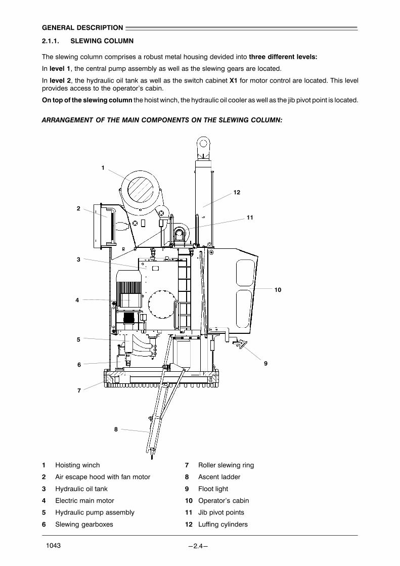
2.1.1. SLEWING COLUMN
The slewing column comprises a robust metal housing devided into three different levels:
In level 1, the central pump assembly as well as the slewing gears are located.
In level 2, the hydraulic oil tank as well as the switch cabinet X1 for motor control are located. This levelprovides access to the operator’s cabin.
On top of the slewing column the hoist winch, the hydraulic oil cooler as well as the jib pivot point is located.
ARRANGEMENT OF THE MAIN COMPONENTS ON THE SLEWING COLUMN:
1 Hoisting winch 7 Roller slewing ring
2 Air escape hood with fan motor 8 Ascent ladder
3 Hydraulic oil tank 9 Floot light
4 Electric main motor 10 Operator’s cabin
5 Hydraulic pump assembly 11 Jib pivot points
6 Slewing gearboxes 12 Luffing cylinders

16
3
5
46
7
CABIN LEVEL (LEVEL 2)
2 8
GENERAL DESCRIPTION
−2.5− 1043
1 Hydraulic oil tank (see section �MAINTENANCE")
2 Electric main motor with hydraulic pump assembly
3 Slewing gearbox with hydraulic motor and multiple disc brake
4 Switch cabinet X1
5 Access to next lower level
6 Luffing cylinders EU, EV
7 Operator’s cabin
8 Emergency descent

1 6
3
8
46
5
Top level
27
5
GENERAL DESCRIPTION
−2.6− 1043
1 Hydraulic motor HU and multiple disc brake H61U for hoisting winch
2 Air escape hood with fan motor 4A−M05
3 Hoisting winch drum
4 Gear cam limit switches
5 Jib pivot
6 Luffing cylinders EU, EV
7 Operator’s cabin
8 Access to next lower level. KEEP HATCH CLOSED DURING SEA VOYAGE !

2
4
5
3
1
2
7
9
8
6
3
GENERAL DESCRIPTION
−2.7− 1043
2.1.2. JIB
The jib consists of a completely enclosed welded box−section construction through which a high degree ofstability is obtained. The hinges at both sides are fittedto the slewing column top and are provided with selfaligning spherical roller bearings. The jib head com�prises the hoisting rope pulley, which guide the hoistrope.
1 Hook block (see detail below)
2 Hoist rope pulley on jib head
3 Hoisting rope
4 Luffing cylinder connection points
5 Connection to the jib hinge sections on the
slewing column
6 Rope fix point on jib head
7 Upper hook block
8 Lower hook block
9 Load hook

GENERAL DESCRIPTION
−2.8− 1043
2.2. TECHNICAL DESCRIPTION OF THE CRANE
2.2.1. GENERAL
The crane mainly consists of the base column, slewing ring, the slewing column, the jib and the hoistingand slewing gears.
All electric, hydraulic and mechanic units as well as the control stand required for operating the crane arehoused inside the slewing column.
The crane is electric− hydraulically driven, i.e. all three movements of the hoist−, slew and jib motion oper�ate hydraulically. One main electric motor is installed to drive the hydraulic assembly.
2.2.2. HOISTING SYSTEM
The hoisting gear consists of one axial piston pump with variable delivery, one variable hydraulic motor andthe necessary control units. The hydraulic motor is flange−mounted to the planetary gear of the hoist winch.The rope drum is situated on top of the slewing column. The multi disc brake is between the hydraulic motorand the winch gear. The bearing of the hoist drum is sealed against sea water.
2.2.3. LUFFING SYSTEM
The luffing system consists of one axial piston pump (variable delivery), two luffing cylinders and the neces�sary control elements. The jib is guided by the hydraulic cylinders, which work in both directions, and there�fore the jib is under constant control.
2.2.4. SLEWING SYSTEM
The slewing system consists of one axial pistion pump, four hydraulic motors, four multi disc brakes andthe necessary control units. The hydraulical function is similiar to the hoisting gear circuit. The slewing gearsare situated in the lower slewing column and are completely sea water tight.
2.2.5. POWER REGULATION
The hoist speed will be automatically proportional reduced at increasing load by the built−in power regula�tor in the variable pump A11VO.
2.2.6. CRANE CONTROL
The hoisting, luffing and slewing movements can be stepless controlled by full hydraulic joysticks. All move�ments can be carried out simultaneously from the control stand.
2.2.7. HEATING
The operator’s cabin can be heated by a seperate fan / heating system.
The switch cabinet, the slip ring, the hydraulic oiltank and the main motor have stand still heaters to avoidcondensation.
THE AUXILLIARY POWER SUPPLY FOR LIGHTING AND HEATING HAS TO BE SWITCHED ON ALL THETIME TO AVOID CONDENSATION IN THE ELECTRIC OR HYDRAULIC SYSTEM !
2.2.8. COOLING
In order to eliminate heat occuring during operation, one combined winch gear and hydraulic oil coolerwith one ventilator is installed. The temperature is automatically regulated by thermostates.
2.2.9. OPERATOR’S CABIN
All control elements for crane control as the control stand with hydr. joystick, emergency push button, switchunit for crane control, lighting and heating, fan forced heating as well as emergency rescue device for emer�gency descent are placed in the cabin.

GENERAL DESCRIPTION
−2.9− 1043
2.2.10. SAFETY DEVICES
2.2.10.1. HYDRAULICS
−BRAKES
The winch for the hoist system as well as the drive gears for the slewing system are equipped with springloaded multiple disc brakes, which are in the applied position without control. The brakes open only if thecorresponding control lever is operated. The brakes close automatically when the control lever is returnedto neutral position, in addition the multiple disc brakes are applied automatically in the event of a power fail�ure on the electric motor or pressure drop in the hydraulic system. The multi disc brakes are automaticallyself adjusting, that means the brakes need not to be re−adjusted.
−ADDITIONAL PROTECTION OF THE JIB MOTION
If the hose connection for movement �jib up" at the luffing cylinders get damaged, the jib movement �down"stops immediately because of the hose fracture safety valves placed at the bottom of both cylinders.Falling back of the jib is prevented by the extreme positions of the piston rods of the double acting hydrauliccylinders.
−OVERPRESSURE PROTECTION
The entire hydraulic system is protected against overpressure by means of pressure limiting valves.
2.2.10.2. ELECTRICS
−EMERGENCY STOP BUTTONS
Emergency stop buttons are installed to ensure an emergency shutdown of the crane if a dangerous situa�tion occures.
They are located:
− at the switch unit X20 (cabin)− at switch cabinet X1− at the acsent ladder
−LIMIT SWITCHES
The winch for the hoist system as well as the luffing system are equipped with with gear cam limit switcheswhich stop the movement at the corresponding limit position.
2.2.10.3. OTHER SAFETY DEVICES
−EMERGENCY HAND PUMP
The emergency hand pump (seperate delivered) can be used to rest the load at a total black out on thecrane.
For operation of the hand pump refer to section "EMERGENCY OPERATIONS"
−EMERGENCY DESCENT/ENTRANCE
The emergency descent from the crane must be done through the front window of the cabin and by useof the rescue device (it is stored in the upper right corner of the cabin)
The use of this rescue device is explained on the following page. The front window can be opend by theprovided handle.
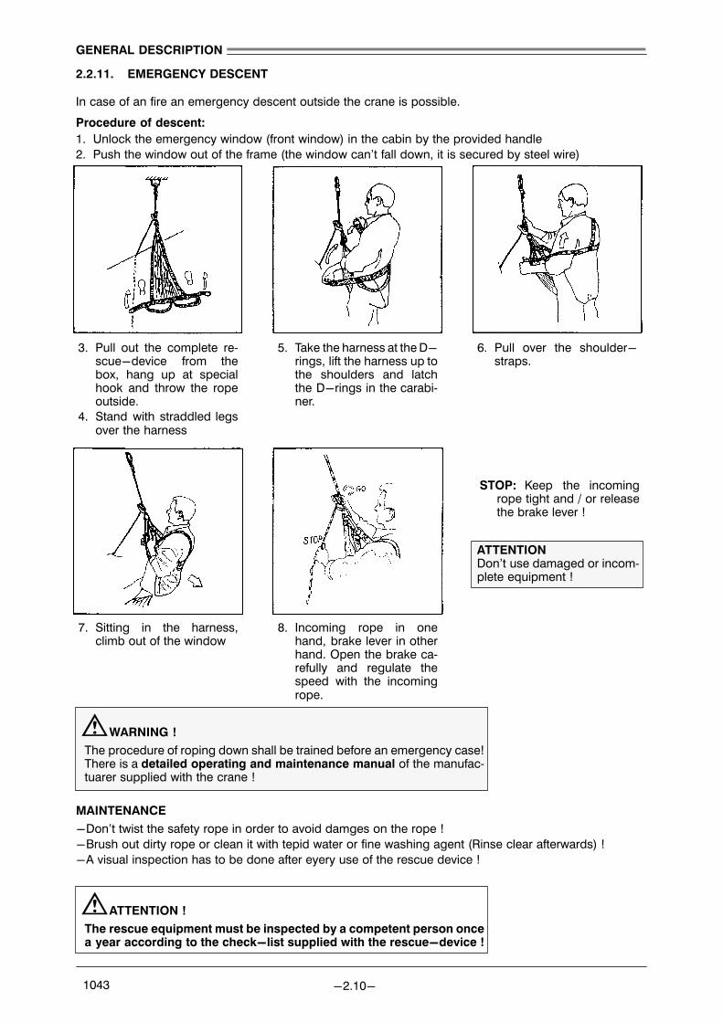
3. Pull out the complete re�scue−device from thebox, hang up at specialhook and throw the ropeoutside.
4. Stand with straddled legsover the harness
5. Take the harness at the D−rings, lift the harness up tothe shoulders and latchthe D−rings in the carabi�ner.
6. Pull over the shoulder−straps.
7. Sitting in the harness,climb out of the window
8. Incoming rope in onehand, brake lever in otherhand. Open the brake ca�refully and regulate thespeed with the incomingrope.
ATTENTIONDon’t use damaged or incom�plete equipment !
STOP: Keep the incomingrope tight and / or releasethe brake lever !
GENERAL DESCRIPTION
−2.10− 1043
2.2.11. EMERGENCY DESCENT
In case of an fire an emergency descent outside the crane is possible.
Procedure of descent:1. Unlock the emergency window (front window) in the cabin by the provided handle2. Push the window out of the frame (the window can’t fall down, it is secured by steel wire)
WARNING !The procedure of roping down shall be trained before an emergency case!There is a detailed operating and maintenance manual of the manufac�tuarer supplied with the crane !
MAINTENANCE−Don’t twist the safety rope in order to avoid damges on the rope !−Brush out dirty rope or clean it with tepid water or fine washing agent (Rinse clear afterwards) !−A visual inspection has to be done after eyery use of the rescue device !
ATTENTION !The rescue equipment must be inspected by a competent person oncea year according to the check−list supplied with the rescue−device !

GENERAL DESCRIPTION
−2.11− 1043
2.2.12. LOAD DIAGRAM

1
5
9
7
10
6
8
2
4
3 3
GENERAL DESCRIPTION
−2.12− 1043
2.3. LAYOUT OF THE OPERATOR’S CABIN
1 Cabin heater2 Joy stick �jib / slew motion"3 Arm rests4 Watertank for windscreen washer5 Driver’s seat6 Entrance door7 Rescue device for emergency descent from the crane8 Switch unit X209 Joy stick �hoist motion"10 Emergency window for emergency descent (see section �EMERGENCY DESCENT")

GENERAL DESCRIPTION
−2.13− 1043
2.3.1. EXPLANATION OF CONTROL ELEMENTS
2.3.1.1. JOY STICK �JIB / SLEW MOTION"
Combined joy stick for stepless hydraulic control of the luffing andslewing system. Both movements can be carried out at the sametime.
The joy stick is spring centered and will automatically return to neu�tral when it is released.
A button on top of the joy stick can be used for operating the hornoutside the cabin.
2.3.1.2. JOY STICK �HOIST MOTION"
Joy stick for stepless hydraulic control of the hoist motion opera�tion can be carried out at the same time with luff or slew motion.
The joy stick is spring centered and will automatically return to neu�tral when it is released.

13
2
4
5
6
12
11
10
8
9
3
1
7
GENERAL DESCRIPTION
−2.14− 1043
2.3.2. SWITCH UNIT X20
1 Switch �screen wiper front"
Pos. �0": offPos. �I": screen wiper operationPos. �II": pump for screen wiper operation
2 Switch �lighting cabin"
For operating the light in the cabin.
3 Pilot light �main motor fault"
The pilot light illuminates if one of the listed faults occurs:− overtemperature protection (PTC) main motor tripped− overcurrent relay (PTC) main motor
GENERAL DESCRIPTION
−2.15− 1043
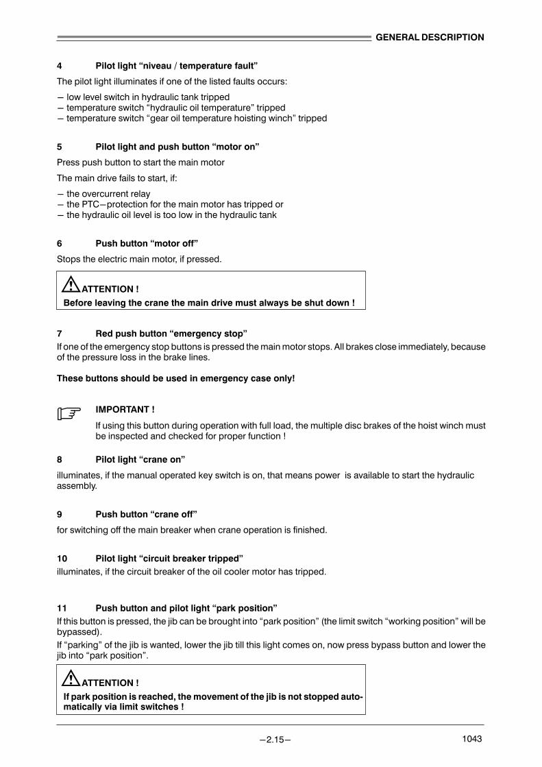
4 Pilot light �niveau / temperature fault"
The pilot light illuminates if one of the listed faults occurs:
− low level switch in hydraulic tank tripped− temperature switch �hydraulic oil temperature" tripped− temperature switch �gear oil temperature hoisting winch" tripped
5 Pilot light and push button �motor on"
Press push button to start the main motor
The main drive fails to start, if:
− the overcurrent relay− the PTC−protection for the main motor has tripped or− the hydraulic oil level is too low in the hydraulic tank
6 Push button �motor off"
Stops the electric main motor, if pressed.
ATTENTION !
Before leaving the crane the main drive must always be shut down !
7 Red push button �emergency stop"If one of the emergency stop buttons is pressed the main motor stops. All brakes close immediately, becauseof the pressure loss in the brake lines.
These buttons should be used in emergency case only!
. IMPORTANT !
If using this button during operation with full load, the multiple disc brakes of the hoist winch mustbe inspected and checked for proper function !
8 Pilot light �crane on"
illuminates, if the manual operated key switch is on, that means power is available to start the hydraulicassembly.
9 Push button �crane off"
for switching off the main breaker when crane operation is finished.
10 Pilot light �circuit breaker tripped"illuminates, if the circuit breaker of the oil cooler motor has tripped.
11 Push button and pilot light �park position"If this button is pressed, the jib can be brought into �park position" (the limit switch �working position" will bebypassed).If �parking" of the jib is wanted, lower the jib till this light comes on, now press bypass button and lower thejib into �park position".
ATTENTION !
If park position is reached, the movement of the jib is not stopped auto�matically via limit switches !

GENERAL DESCRIPTION
−2.16− 1043
12 Switch �lighting crane"
For operating the lights inside the slewing column. An additional switch is located at the ascent ladder.
13 Switch �floodlights"
For operating the flood light at the jib head.

1
2
3
4
5
6
GENERAL DESCRIPTION
−2.17− 1043
2.4. CONTROLS ON THE SWITCH CABINET X1
1 Air inlet with filter (clean or exchange the filter approx. every 3000 working hours) and fanX1−M01
2 Air outlet with filter (clean or exchange the filter approx. every 3000 working hours)
3 Main switch "AUXILIARY SUPPLY" X1−S02. Operates the power supply for the entire lighting and heating system on the crane. SWITCH OFF ONLY FOR SERVICE WORK IN THIS SYSTEM!
4 Red push button "EMERGENCY STOP". X1−S01. Function see "EMERGENCY STOP" on SWITCH UNIT X20.
5 MOTOR OPERATION HOURS COUNTER. X1−P01. This value is used to determine the crane’s maintenance intervalls.
6 Main switch "CRANE POWER SUPPLY". X1−Q01. Turn to switch on. Switch cabinet door can’t be opened, when the switch is in the "ON" position.
WARNING !
BEFORE OPENING ANY ELECTRICAL EQUIPMENT, IT IS ESSENTIALTO SWITCH OFF THE POWER SUPPLY !

GENERAL DESCRIPTION
−2.18− 1043
GENERAL DESCRIPTION
−2.19− 1043
2.5. PREPARATIONS FOR CRANE OPERATION
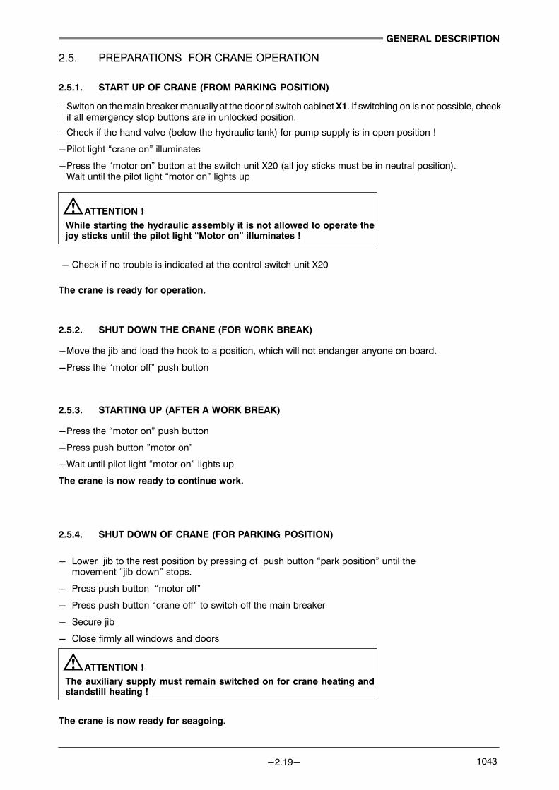
2.5.1. START UP OF CRANE (FROM PARKING POSITION)
−Switch on the main breaker manually at the door of switch cabinet X1. If switching on is not possible, checkif all emergency stop buttons are in unlocked position.
−Check if the hand valve (below the hydraulic tank) for pump supply is in open position !
−Pilot light �crane on" illuminates
−Press the �motor on" button at the switch unit X20 (all joy sticks must be in neutral position). Wait until the pilot light �motor on" lights up
ATTENTION !While starting the hydraulic assembly it is not allowed to operate thejoy sticks until the pilot light �Motor on" illuminates !
− Check if no trouble is indicated at the control switch unit X20
The crane is ready for operation.
2.5.2. SHUT DOWN THE CRANE (FOR WORK BREAK)
−Move the jib and load the hook to a position, which will not endanger anyone on board.
−Press the �motor off" push button
2.5.3. STARTING UP (AFTER A WORK BREAK)
−Press the �motor on" push button
−Press push button "motor on"
−Wait until pilot light �motor on" lights up
The crane is now ready to continue work.
2.5.4. SHUT DOWN OF CRANE (FOR PARKING POSITION)
− Lower jib to the rest position by pressing of push button �park position" until the movement �jib down" stops.
− Press push button �motor off"
− Press push button �crane off" to switch off the main breaker
− Secure jib
− Close firmly all windows and doors
ATTENTION !The auxiliary supply must remain switched on for crane heating andstandstill heating !
The crane is now ready for seagoing.
b
a
dc
f
e
GENERAL DESCRIPTION
−2.20− 1043
2.6. CRANE OPERATIONSafety instructions:
DANGER !−Before starting hook operation the crane must be in operational condition, meaningno trouble is indicated !
−At a failure on the load moment limiting system crane operation may not be startedresp. operation must be stopped immediately.
−Do not lift heavier loads as indicated on the load diagram for this operation mode !−Crane operation must be stopped at a windspeed more than 25 m/sec.
Operation:
−Start up crane as described in part �Preparations for crane operation".
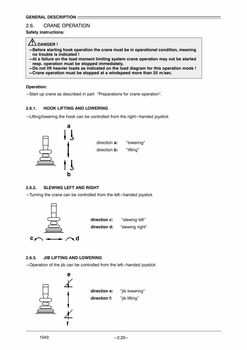
2.6.1. HOOK LIFTING AND LOWERING
−Lifting/lowering the hook can be controlled from the right−handed joystick
direction a: "lowering"
direction b: "lifting"
2.6.2. SLEWING LEFT AND RIGHT
−Turning the crane can be controlled from the left−handed joystick
direction c: �slewing left"
direction d: �slewing right"
2.6.3. JIB LIFTING AND LOWERING
−Operation of the jib can be controlled from the left−handed joystick
direction e: �jib lowering"
direction f: �jib lifting"

MAINTENANCE
−3.1− 1043
INDEX
3. MAINTENANCE 3.3. . . . . . . . . . . . . . . . . . . . . . . . . . . . . . . . . . . . . . . . . . . . . . .
3.1. GENERAL 3.3. . . . . . . . . . . . . . . . . . . . . . . . . . . . . . . . . . . . . . . . . . . . . . . . . . . . .
3.1.1. MAINTENANCE INTERVALS 3.3. . . . . . . . . . . . . . . . . . . . . . . . . . . . . . . . . . . . . . . . . . . . . . . . . 3.1.2. HIGH ADHESION LUBRICANT OR UNDERWATER GREASE 3.3. . . . . . . . . . . . . . . . . . . . . 3.1.3. DISPOSAL OF USED MATERIALS 3.3. . . . . . . . . . . . . . . . . . . . . . . . . . . . . . . . . . . . . . . . . . . .
3.2. SPECIAL SAFETY REGULATIONS 3.4. . . . . . . . . . . . . . . . . . . . . . . . . . . . . . . .
3.2.1. GENERAL MAINTENANCE SAFETY 3.4. . . . . . . . . . . . . . . . . . . . . . . . . . . . . . . . . . . . . . . . . . . 3.2.2. FIRE AND EXPLOSION PREVENTION 3.5. . . . . . . . . . . . . . . . . . . . . . . . . . . . . . . . . . . . . . . . . 3.2.3. HANDLING AND DISPOSAL INSTRUCTIONS 3.6. . . . . . . . . . . . . . . . . . . . . . . . . . . . . . . . . . . 3.2.4. LUBRICANTS AND OILS 3.7. . . . . . . . . . . . . . . . . . . . . . . . . . . . . . . . . . . . . . . . . . . . . . . . . . . . . 3.2.5. MAINTENANCE OF OIL COOLERS 3.7. . . . . . . . . . . . . . . . . . . . . . . . . . . . . . . . . . . . . . . . . . . 3.2.6. HYDRAULIC OIL FILLING 3.8. . . . . . . . . . . . . . . . . . . . . . . . . . . . . . . . . . . . . . . . . . . . . . . . . . . .
3.3. MAINTENANCE OF HYDRAULIC SYSTEM 3.9. . . . . . . . . . . . . . . . . . . . . . . .
3.3.1. GENERAL 3.9. . . . . . . . . . . . . . . . . . . . . . . . . . . . . . . . . . . . . . . . . . . . . . . . . . . . . . . . . . . . . . . . . 3.3.2. FILTER ELEMENTS 3.9. . . . . . . . . . . . . . . . . . . . . . . . . . . . . . . . . . . . . . . . . . . . . . . . . . . . . . . . . 3.3.3. HYDRAULIC FLUID 3.9. . . . . . . . . . . . . . . . . . . . . . . . . . . . . . . . . . . . . . . . . . . . . . . . . . . . . . . . . 3.3.4. FLUSHING OF HYDRAULIC CIRCUIT AND PREFILLING THE PUMPS 3.9. . . . . . . . . . . . . 3.3.5. HYDRAULIC LINES AND HOSES 3.10. . . . . . . . . . . . . . . . . . . . . . . . . . . . . . . . . . . . . . . . . . . . . 3.3.6. VALVE AND FILTER PLATE AGGREGATE ROOM 3.11. . . . . . . . . . . . . . . . . . . . . . . . . . . . . . . 3.3.7. RETURN FLOW FILTER HYDRAULIC OIL TANK 3.12. . . . . . . . . . . . . . . . . . . . . . . . . . . . . . . . .
3.4. PRESSURE ACCUMULATORS 3.13. . . . . . . . . . . . . . . . . . . . . . . . . . . . . . . . . . .
3.4.1. GENERAL 3.13. . . . . . . . . . . . . . . . . . . . . . . . . . . . . . . . . . . . . . . . . . . . . . . . . . . . . . . . . . . . . . . . . 3.4.2. SAFETY INSTRUCTIONS 3.13. . . . . . . . . . . . . . . . . . . . . . . . . . . . . . . . . . . . . . . . . . . . . . . . . . . . 3.4.3. ACCUMULATOR TYPES IN THE CRANE 3.13. . . . . . . . . . . . . . . . . . . . . . . . . . . . . . . . . . . . . . .
3.5. LIEBHERR CONDITION MONITORING 3.14. . . . . . . . . . . . . . . . . . . . . . . . . . .
3.5.1. GENERAL 3.14. . . . . . . . . . . . . . . . . . . . . . . . . . . . . . . . . . . . . . . . . . . . . . . . . . . . . . . . . . . . . . . . . 3.5.2. TECHNIQUES EMPLOYED IN CONDITION MONITORING 3.14. . . . . . . . . . . . . . . . . . . . . . . 3.5.3. OIL SAMPLE / OIL EXCHANGE 3.16. . . . . . . . . . . . . . . . . . . . . . . . . . . . . . . . . . . . . . . . . . . . . . . 3.5.4. TAKING AN OIL SAMPLE 3.17. . . . . . . . . . . . . . . . . . . . . . . . . . . . . . . . . . . . . . . . . . . . . . . . . . . . 3.5.5. CONDITION MONITORING REPORT 3.18. . . . . . . . . . . . . . . . . . . . . . . . . . . . . . . . . . . . . . . . . .
3.6. GEARBOXES 3.19. . . . . . . . . . . . . . . . . . . . . . . . . . . . . . . . . . . . . . . . . . . . . . . . . .
3.6.1. SLEWING GEARBOXES 3.19. . . . . . . . . . . . . . . . . . . . . . . . . . . . . . . . . . . . . . . . . . . . . . . . . . . . . 3.6.2. HOIST WINCH GEARBOX 3.20. . . . . . . . . . . . . . . . . . . . . . . . . . . . . . . . . . . . . . . . . . . . . . . . . . .
3.7. MULTIPLE DISC BRAKES 3.22. . . . . . . . . . . . . . . . . . . . . . . . . . . . . . . . . . . . . . .
3.8. INSTRUCTIONS FOR USE OF CRANE ROPES 3.23. . . . . . . . . . . . . . . . . . . .
3.8.1. SELECTION OF WIRE ROPES 3.23. . . . . . . . . . . . . . . . . . . . . . . . . . . . . . . . . . . . . . . . . . . . . . . . 3.8.2. ROPE INSTALLATION 3.23. . . . . . . . . . . . . . . . . . . . . . . . . . . . . . . . . . . . . . . . . . . . . . . . . . . . . . . 3.8.3. MAINTENANCE 3.24. . . . . . . . . . . . . . . . . . . . . . . . . . . . . . . . . . . . . . . . . . . . . . . . . . . . . . . . . . . . 3.8.4. INSPECTION 3.24. . . . . . . . . . . . . . . . . . . . . . . . . . . . . . . . . . . . . . . . . . . . . . . . . . . . . . . . . . . . . . . 3.8.5. INSTRUCTIONS FOR UNTWISTING OF HOIST ROPES 3.25. . . . . . . . . . . . . . . . . . . . . . . . . . 3.8.6. DISCARD CRITERIA 3.26. . . . . . . . . . . . . . . . . . . . . . . . . . . . . . . . . . . . . . . . . . . . . . . . . . . . . . . .

MAINTENANCE
−3.2− 1043
3.9. REPLACEMENT OF ROPES 3.27. . . . . . . . . . . . . . . . . . . . . . . . . . . . . . . . . . . . .
3.9.1. REEVING HOIST GEAR 3.27. . . . . . . . . . . . . . . . . . . . . . . . . . . . . . . . . . . . . . . . . . . . . . . . . . . . .
3.10. ROPE PULLEYS 3.29. . . . . . . . . . . . . . . . . . . . . . . . . . . . . . . . . . . . . . . . . . . . . . .
3.10.1. GENERAL LAYOUT 3.29. . . . . . . . . . . . . . . . . . . . . . . . . . . . . . . . . . . . . . . . . . . . . . . . . . . . . . . . . 3.10.2. STORAGE 3.29. . . . . . . . . . . . . . . . . . . . . . . . . . . . . . . . . . . . . . . . . . . . . . . . . . . . . . . . . . . . . . . . . 3.10.3. TRANSPORT 3.29. . . . . . . . . . . . . . . . . . . . . . . . . . . . . . . . . . . . . . . . . . . . . . . . . . . . . . . . . . . . . . . 3.10.4. DURING OPERATION 3.30. . . . . . . . . . . . . . . . . . . . . . . . . . . . . . . . . . . . . . . . . . . . . . . . . . . . . . . 3.10.5. INSPECTION AND MAINTENANCE 3.30. . . . . . . . . . . . . . . . . . . . . . . . . . . . . . . . . . . . . . . . . . . 3.10.6. RESISTANCE TO CHEMICAL PRODUCTS OF LAMIGAMIDR ROPE PULLEYS 3.31. . . . . .
3.11. ROLLER SLEWING RING 3.32. . . . . . . . . . . . . . . . . . . . . . . . . . . . . . . . . . . . . . .
3.12. ELECTRICAL SYSTEM 3.33. . . . . . . . . . . . . . . . . . . . . . . . . . . . . . . . . . . . . . . . . .
3.12.1. MAINTENANCE TO THE ELECTRICAL SYSTEM 3.33. . . . . . . . . . . . . . . . . . . . . . . . . . . . . . . . 3.12.2. WET CLEANING 3.33. . . . . . . . . . . . . . . . . . . . . . . . . . . . . . . . . . . . . . . . . . . . . . . . . . . . . . . . . . . .
3.13. MAINTENANCE INSTRUCTIONS FOR SLIP RING UNIT 3.34. . . . . . . . . . . . .
3.13.1. TERMINAL BOX 3.34. . . . . . . . . . . . . . . . . . . . . . . . . . . . . . . . . . . . . . . . . . . . . . . . . . . . . . . . . . . . 3.13.2. POWER SECTION 3.34. . . . . . . . . . . . . . . . . . . . . . . . . . . . . . . . . . . . . . . . . . . . . . . . . . . . . . . . . . 3.13.3. SIGNAL SECTION 3.34. . . . . . . . . . . . . . . . . . . . . . . . . . . . . . . . . . . . . . . . . . . . . . . . . . . . . . . . . . 3.13.4. CABLE INSULATION 3.34. . . . . . . . . . . . . . . . . . . . . . . . . . . . . . . . . . . . . . . . . . . . . . . . . . . . . . . .
3.14. LUBRICATION AND GREASING DIAGRAM 3.35. . . . . . . . . . . . . . . . . . . . . . . .
3.15. MAINTENANCE LISTS 3.37. . . . . . . . . . . . . . . . . . . . . . . . . . . . . . . . . . . . . . . . .
3.15.1. GENERAL INFORMATION 3.37. . . . . . . . . . . . . . . . . . . . . . . . . . . . . . . . . . . . . . . . . . . . . . . . . . . 3.15.2. OVERVIEW MAINTENANCE INTERVALS 3.37. . . . . . . . . . . . . . . . . . . . . . . . . . . . . . . . . . . . . . . 3.15.3. FILLING QUANTITIES 3.36. . . . . . . . . . . . . . . . . . . . . . . . . . . . . . . . . . . . . . . . . . . . . . . . . . . . . . . 3.15.4. EVERY 10 HRS / DAILY 3.39. . . . . . . . . . . . . . . . . . . . . . . . . . . . . . . . . . . . . . . . . . . . . . . . . . . . . . 3.15.5. EVERY 50 HRS / WEEKLY 3.41. . . . . . . . . . . . . . . . . . . . . . . . . . . . . . . . . . . . . . . . . . . . . . . . . . . 3.15.6. FIRST 100 HRS / AFTER 2 WEEKS 3.43. . . . . . . . . . . . . . . . . . . . . . . . . . . . . . . . . . . . . . . . . . . 3.15.7. FIRST 500 HRS / AFTER 3 MONTHS 3.45. . . . . . . . . . . . . . . . . . . . . . . . . . . . . . . . . . . . . . . . . . 3.15.8. EVERY 500 HRS / EVERY 3 MONTHS 3.47. . . . . . . . . . . . . . . . . . . . . . . . . . . . . . . . . . . . . . . . . 3.15.9. FIRST 1000 HRS / AFTER 6 MONTHS 3.49. . . . . . . . . . . . . . . . . . . . . . . . . . . . . . . . . . . . . . . . . 3.15.10. EVERY 2000 HRS / EVERY YEAR 3.51. . . . . . . . . . . . . . . . . . . . . . . . . . . . . . . . . . . . . . . . . . . . .
3.16. SERVICE SPARE−PARTS AND STANDARD TOOLS 3.53. . . . . . . . . . . . . . . .
TABLE OF LUBRICANTS

MAINTENANCE
−3.3− 1043
3. MAINTENANCE
3.1. GENERAL
Routine and preventive maintenance measures are essential for a safe and efficient operation of the crane.Failure of adequate maintenance may result in costly, unscheduled breakdown and dangerous situations.
Cleanliness is required for the operation of the hydraulic system. Filters of any type as well as the hydraulicoil have to be checked at appropriate intervals.
Periodical exchange of the oil used in the different gearboxes must be done.
All movable parts like winch bearings, hinge sections, rope pulleys, slewing bearing, ropes, doors, ventila�tion flaps etc. must always be greased.
For regular service intervals refer to attached maintenance list in section "MAINTENANCE LIST".
. IMPORTANT !
Special care must be taken when the crane is out of operation. The standstill heatings must beon. Important pressures should be checked at extreme outside temperatures (e.g. feed pressure,control pressure etc. It is necessary to check the hose armatures, which are mounted on the out�side of the crane and are exposed to the seawater, at regular intervals.
While greasing the bearings of the winches and the main slewing bearing ring, the winches as wellas the slewing ring has to be turned slowly to ensure an adequate grease distribution.
The maintenance intervals indicated in the maintenance list depend on the actual operating hoursof the crane. Should the crane be standing for more then a month, then the crane has to be oper�ated every month for at least two hours. In that time all the greasing, oil inspections and oil levelchecks have to be done.
The crane has to be preserved, if not in operation for more than three months. Preservation instruc�tions are obtainable through the LIEBHERR service department.
The bolts of the main slewing bearing have to be kept greased after erection and regreased afterevery inspection.
ATTENTION !Switch off the heater inside the hydraulic oil tank before exchanging ordraining the oil !
3.1.1. MAINTENANCE INTERVALS
The maintenance intervals mentioned in the section MAINTENANCE LIST are guiding times and should beobserved.
3.1.2. HIGH ADHESION LUBRICANT OR UNDERWATER GREASE
Gear rim of main slewing bearing must always be greased
Ropes must always be greased
3.1.3. DISPOSAL OF USED MATERIALS
DISPOSAL ! WHEN CHANGING OIL AND GREASE, BATTERIES, ETC.−USED MATERIALS MUST BE PROP�ERLY DISPOSED OF IN ACCORDANCE WITH THE RELEVANT STATE REGULATIONS !CONTAMINATION OF SOIL, SEWAGE AND WATER SYSTEMS MUST BE AVOIDED !

MAINTENANCE
−3.4− 1043
3.2. SPECIAL SAFETY REGULATIONS
3.2.1. GENERAL MAINTENANCE SAFETY
−STUDY THE INSTRUCTION− AND MAINTENANCE MANUAL before operating or servicing the crane.Make certain that you have additional information for special attachments of your crane, read it and under�stand it. IF IN DOUBT OR ANY INFORMATION REQUIRED, PLEASE CONTACT YOUR NEAREST LIEB�HERR SERVICE STATION (Contacts to LIEBHERR Service stations see SECTION 1 OF THIS MANUAL).
−ALLOW ONLY TRAINED AND AUTHORIZED PERSONNEL TO OPERATE, MAINTAIN, SERVICE OR RE�PAIR THE LIEBHERR DECK CRANE.
−WHEN MAKING REPLACEMENTS − USE ONLY ORIGINAL LIEBHERR SPARE PARTS ! THIS IS ABSO�LUTELY NECESSARY FOR OPERATING YOUR CRANE SAFELY.
−MAINTENANCE WORK SHOULD BE PERFORMED AS OUTLINED IN THE MAINTENANCE GUIDLINESAND INTERVALS OF THIS MANUAL.
−PERFORM ONLY WORK YOU UNDERSTAND, USING THE MAINTENANCE MANUAL AND SPARE PARTMANUAL AS GUIDLINE.
−WEAR PROPER WORKING− AND SAFETY CLOTHING (coverall, safety boots, hard hat, safety glassesand gloves, ear protection, etc.) WHEN PERFORMING SERVICE OR REPAIR WORK.KNOW YOUR LOCAL SAFETY RULES AND REGULATIONS.
−KEEP UNAUTHORIZED PERSONNEL FROM THE CRANE WHEN PERFORMING MAINTENANCE− orREPAIR WORK.
−BEFORE SERVICING THE CRANE, ATTACH A "DO NOT OPERATE" TAG ON THE ACCESS LADDERAND THE CONTROL PANEL.
−DO NOT USE FLAMMABLE FLUIDS TO CLEAN THE CRANE.
−NEVER CHECK FOR LEAKS WITH YOUR BARE HANDS AND / OR WITHOUT SAFETY GLASSES.Fluids escaping from a small hole can have enough force to penetrate skin.
−DO NOT DISCONNECT LINES or HOSES, FITTINGS, CAPS or COVERS WHILE THE HYDRAULICSYSTEM, ENGINE FUEL or COOLING SYSTEM is PRESSURIZED. ALWAYS LOWER A LOAD OR AT�TACHMENT TO GROUND FIRST − LOWER THE JIB AND TOWER INTO MAINTENANCE POSITION.SHUT OFF THE MAIN MOTOR, AND RELEASE THE RESSURE FIRST. After servicing, ensure that all lines,hoses and fittings are properly connected and all caps and covers are closed.
−DO NOT LIFT HEAVY COMPONENTS − USE PROPER LIFTING DEVICES SUCH AS CHAIN BLOCKS,CRANES, etc.
−NEVER USE DAMAGED OR INSUFFICIENT WIRE ROPES, CHAINS AND SLINGS. Always wearSAFETY GLOVES when handling wire ropes.
−NEVER USE METAL ON METAL SUPPORTS.
continued / ......

MAINTENANCE
−3.5− 1043
3.2.2. FIRE AND EXPLOSION PREVENTION
−WHEN PERFORMING HOT WORK (welding, etc.) ALWAYS HAVE A FIRE EXTINGUISHER ONSTAND−BY.
−NEVER STORE FLAMMABLE FLUIDS ON THE CRANE EXCEPT IN THE STORAGE TANKSINSTALLED FOR THE CRANE OPERATION.
−FREQUENTLY CHECK THE ELECTRICAL SYSTEM AND CORRECT ALL WIRING DEFECTS.
−DO NOT USE FLAMMABLE MATERIALS / FLUIDS TO CLEAN THE CRANE.
−INSPECT PERIODICALLY ALL COMPONENTS, LINES, TUBES AND HOSES FOR EVENTUAL LEAK�AGES OR MECHANICAL DAMAGE. REPLACE OR REPAIR ANY DAMAGED COMPONENTS.BE AWARE, OILLEAKS CAN CAUSE FIRES !
−KNOW THE LOCATION OF THE FIRE EXTINGUISHERS AND BE FAMILIAR WITH ITS OPERATION.

EXPLOSIVE
HIGHLY INFLAMMABLE
FIRE SUPPORTIVE MATERIALS
POISONOUS
NOXIOUS
CORROSIVE, CAUSTIC
MAINTENANCE
−3.6− 1043
3.2.3. HANDLING AND DISPOSAL INSTRUCTIONS
GENERAL
THE ENVIRONMENT IS OF GREAT IMPORTANCE TO LIEBHERR BOTH IN THE FAC�TORY DURING PRODUCTION OF OUR GOODS AND IN THE DESIGN OF OUR PRODUCTS.
−energy saving crane powering concept
−less pollutants, lower gasoline consumption, lower noise levels
HANDLING AND DISPOSAL INSTRUCTIONS
When chemical cleaning, testing compounds and lubricants are used, the pertinent danger and also han�dling information on the packing units is to be adhered to and appropriate protective devices to be used.
. IMPORTANT !
DO NOT USE FLAMMABLE FLUIDS TO CLEAN THE CRANE ! NEVER STORE FLAMMABLE OROTHER DANGEROUS FLUIDS / GOODS ON THE CRANE !
DANGERS
. IMPORTANT !
LUBRICANTS, PAINTS, THINNERS AND CLEANING COMPONENTS ARE TO BE STORED ORPRESERVED ALWAYS IN CLOSED VESSELS. NEVER STORE FLAMMABLE FLUIDS ON THE CRANE EXCEPT IN THE STORAGE TANKS(HYDRAULIC OIL, etc.) INSTALLED FOR THE CRANE OPERATION.
ATTENTION !FILLED UP AND LABELLED PACKING UNITS OF USED LUBRICANTS, OLD PARTS, PAINTS, THINNERS AND CLEANING COMPONENTS TO BERETURNED UNDER MAXIMUM SAFETY AND IN COMPLIANCE TO SPECIAL LOCAL RULES AND REGULATIONS TO YOUR NEXT DISPOSALDEPOSITION.
MAINTENANCE
−3.7− 1043
3.2.4. LUBRICANTS AND OILS
Should only be chosen from the TABLE OF LUBRICANTS, which is attached to the end of this section.
NOTE:
Since we know that the ordinary commercialized multi purpose greases do not always comply with the re�quirements of our cranes, we have developed a grease paste in close collaboration with our suppliers.
This new grease paste has, after extensive tests, proved to be very suitable for the best greasing of ourcranes and thus has been used for some time now in our factory for the greasing of cranes.
The working temperature of this grease paste range is from − 50°C to + 90°C. The grease paste is ex�tremely resistant to pressure, water, can easily be conveyed through grease pipes and has a very high drip�ping point.
We are pleased to offer this grease paste as follows:
AVIALITH 2EP special paste in cartridges to 400 g
3.2.5. MAINTENANCE OF OIL COOLERS
The cooling lamellas of the hydraulic oil cooler unit and winch gear oil cooler unit have to be FREE OF DIRTto achieve the maximum cooling capacity.
Therefore the lamellas have to be inspected visually at least every week and cleaned if necessary.
3.2.5.1. CLEANING OF OIL COOLER UNIT
Depending on the kind of the dirt on the oil cooler unit the following methods may be used:
DRY DUST = > Clean with air pressure (max. pressure 10 bar)
WET DUST = > Clean with steam cleaner (max. pressure 150 bar)
OILY DUST = > Clean with steam cleaner (max. pressure 150 bar) and add solvent cleaner
. NOTE !
If in doubt of the correct cleaning method for a certain type of dirt, contact any LIEBHERR represen�tative for advice !

1 2 3
4
5
6 7 8
4
MAINTENANCE
−3.8− 1043
3.2.6. HYDRAULIC OIL FILLING
Hand filled through the return flow filter on top of the hydraulic oil tank. Check the oil level at the inspectionglass on the side wall of the hydraulic oil tank. The oil level should always be between the MAXIMUM andMINIMUM mark.
. NOTE !
Jib must be in the jib rest, when checking hydraulic oil level !
Components at hydraulic tank:
1 Air breather 5 Inspection cover
2 Oil level and temperature sensor 6 Drainage cock
3 Flow back filter 7 Oil supply shut−off valve
4 Inspection glasses (oil level and temperature) 8 Tank heater
ATTENTION !Keep SUCTION SHUT OFF VALVE open all the time ! Close ONLY forinspection or service purpose. Before start−up of main motor checkopen position of shut off valve !

Filter cover to be removed for exchange
Oil inlet
Filter element
Oil outlet Oil outlet
Tank plate
RETURN FLOW FILTERElectric or mechanic
dirt indicatior
Safety bypass valvein case of dirty filter
Oil outlet Oil inlet
Filter element
Filter cover to be removed for exchange
PRESSURE FILTER
MAINTENANCE
−3.9− 1043
3.3. MAINTENANCE OF HYDRAULIC SYSTEM
3.3.1. GENERAL
The correct function of the hydraulic system depends on maintenance. The biggest problem is impurity ofthe hydraulic oil. The checking of filters is very important and the renewing as well as the cleaning of filtersand oil should be carried out according to the maintenance list.
Check the hydraulic system daily for leakages.
3.3.2. FILTER ELEMENTS
Initially the filter cartridge must be exchanged after 100 working hours and then every 500 workinghours.
3.3.3. HYDRAULIC FLUID
Change the oil initially after apporximately 500 working hours and then every 1500 working hours.We recommend that a oil sample of the used hydraulic fluid (approx. 0,25 l), which has to be drawn fromthe system (out of a filter), is submitted to the oil supplier for analysis. The oil supplier will inform you aboutthe condition of the oil and recommend a new time for an oil exchange.Hydraulic oil cleanliness requirement code: 18/15 ISO 4406
9 NAS 1638
At first operation used hydraulic oil: FLUID ATF 66 M of AVIA (temp. range: −25°C to +45°C)
3.3.4. FLUSHING OF HYDRAULIC CIRCUIT AND PREFILLING THE PUMPS
It is necessary to flush the hydraulic circuits, if any dirt or solid particles have penetrated. This can occurwhen a pump or motor is damaged or a valve or cylinder (ram) fails. Depending on the nature and extentof the damage, flush thoroughly all affected pipes, filters and the hydraulic oil tank.
. IMPORTANT !
Before operating the crane after an oil exchange or an pump repair, all pumps and respective suc�ction lines must be prefilled with hydraulic oil !

MAINTENANCE
−3.10− 1043
3.3.5. HYDRAULIC LINES AND HOSES
3.3.5.1. GENERAL
. IMPORTANT !
HYDRAULIC LINES, HOSES AND FITTINGS MAY NEVER BE REPAIRED !Any damaged sections must be replaced immediately.
ATTENTION !Pressurized oil can cause body injuries or fires !
3.3.5.2. STORAGE
Even when hoses and lines are installed, stored and used according to specification − they undergo a natu�ral aging process. For that reason, their service life is limited.
Improper storage, mechanical damage and improper use are the most frequent causes of hose fractures.
. NOTE !
USE ONLY ORIGINAL SPARE PARTS according to manufacturers specification.For replacement to the units we recommend that you acquire the necessary knowledge first or youask for assistance / advise from your local LIEBHERR CUSTOMER SERVICE.
3.3.5.3. SERVICE LIFE
. NOTE !
THE SERVICE LIFE OF A HYDRAULIC HOSE MAY NOT EXCEED 6 YEARS, FROM THE DATE OFTHE LIEBHERR LABEL DATE ON THE HOSE CONNECTION. ADDITIONALLY CHECK THEMANUFACTURES DATE ON THE HOSE. THE DATE BETWEEN THE MANUFACTURES DATEAND THE DATE OF THE LIEBHERR LABEL SHOULD NOT EXCEED 2 YEARS.
3.3.5.4. INDICATION OF HOSES
Using hoses and lines close to the permitted working limit can shorten the service life (for exampleat high temperatures, frequent working cycles, extreme high impulse frequencies, multi shift opera�tion or round the clock operations).
3.3.5.5. REPLACEMENT AND INSPECTION OF HOSES
Hoses and lines must be replaced if any of the following points are found during an inspection:− Damage on the external layer into the inner layer (such as chaffing, cuts and rips)− Brittleness of the outer layer (crack formation of the hose material)− Changes in shape, which differ from the natural shape of the hose or line, when under pressure or
when not pressurized, or in bends and curves − such as separation of layers, blister orbubble formation.
− Leakages− Non observance of installation requirements− Damage or deformation of hose fittings, which might reduce the strengths of the fitting or the
connection between hose and fitting− Any movement of the hose away from the fitting− Corrosion on fittings, which might reduce the function or the strength of the fitting− Storage or service life has been exceeded
. NOTE !
To avoid excessive leaks a KNF VACUUM−PUMP could be connected to the hydraulic oil tank.Route or install the hoses and lines properly. DO NOT MIX UP CONNECTIONS !
DISPOSAL ! USED MATERIALS MUST BE PROPERLY DISPOSED OF INACCORDANCE WITH THE RELEVANT STATE REGULATIONS !
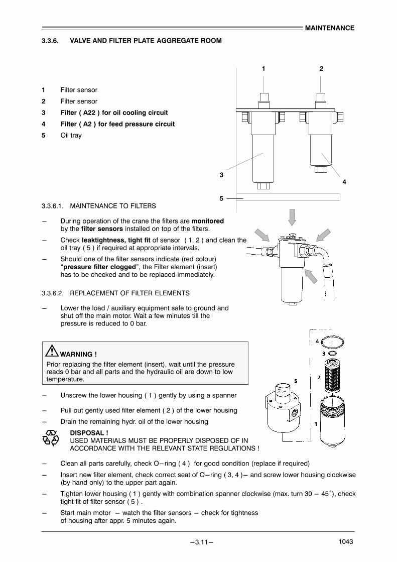
1 2
34
5
MAINTENANCE
−3.11− 1043
3.3.6. VALVE AND FILTER PLATE AGGREGATE ROOM
1 Filter sensor
2 Filter sensor
3 Filter ( A22 ) for oil cooling circuit
4 Filter ( A2 ) for feed pressure circuit
5 Oil tray
3.3.6.1. MAINTENANCE TO FILTERS
− During operation of the crane the filters are monitoredby the filter sensors installed on top of the filters.
− Check leaktightness, tight fit of sensor ( 1, 2 ) and clean theoil tray ( 5 ) if required at appropriate intervals.
− Should one of the filter sensors indicate (red colour) �pressure filter clogged", the Filter element (insert)has to be checked and to be replaced immediately.
3.3.6.2. REPLACEMENT OF FILTER ELEMENTS
− Lower the load / auxiliary equipment safe to ground andshut off the main motor. Wait a few minutes till thepressure is reduced to 0 bar.
WARNING !Prior replacing the filter element (insert), wait until the pressure reads 0 bar and all parts and the hydraulic oil are down to lowtemperature.
− Unscrew the lower housing ( 1 ) gently by using a spanner
− Pull out gently used filter element ( 2 ) of the lower housing
− Drain the remaining hydr. oil of the lower housing
DISPOSAL ! USED MATERIALS MUST BE PROPERLY DISPOSED OF INACCORDANCE WITH THE RELEVANT STATE REGULATIONS !
− Clean all parts carefully, check O−ring ( 4 ) for good condition (replace if required)
− Insert new filter element, check correct seat of O−ring ( 3, 4 )− and screw lower housing clockwise(by hand only) to the upper part again.
− Tighten lower housing ( 1 ) gently with combination spanner clockwise (max. turn 30 − 45°), checktight fit of filter sensor ( 5 ) .
− Start main motor − watch the filter sensors − check for tightness of housing after appr. 5 minutes again.

1 screw, washer2 cover
3 sealing ring
4 magnet stick
5 tension spring
6 pressure piece
7 O−ring
8 filter element
1
3
5
8
7
6
2
4
9
9 filter housing
1
3
4
2
MAINTENANCE
−3.12− 1043
3.3.7. RETURN FLOW FILTER HYDRAULIC OIL TANK
ARRANGEMENT
1 Filter indication device: green = satisfactory, red = filter element blocked
2 Filter cover
3 Filter housing of Return flow filter A7
4 Hydraulic oil tank
3.3.7.1. MAINTENANCE TO RETURN FLOW FILTERS
− Check leaktightness, tight fit at appropriate intervals.
− Should the indication device reads red �= filter element clogged" Filter element (insert) has to be checked and to bereplaced immediately (latest at next working brake).
3.3.7.2. REPLACEMENT OF FILTER ELEMENTS
− Lower the load / auxiliary equipment safe to ground andshut off the main motor. Wait a few minutes till thepressure is reduced to 0 bar.
WARNING !Prior replacing the filter element (insert), wait until thepressure reads 0 bar , all parts and the hydraulic oil are downto low temperature.
− Remove the cover ( 2 ) gentlyby using a spanner for the screws (1) of adequate size.
− Pull out gently magnet piece (4) and tension spring (5),pressure piece (6), O−ring (7) and used filter element (8) ofthe filter housing,Check the magnetic rod (there must be onlymetal dust = normal abbrasion)
DISPOSAL ! USED MATERIALS MUST BE PROPERLY DISPOSED OF INACCORDANCE WITH THE RELEVANT STATE REGULATIONS !
− Clean all parts carefully (1 − 7, 9), check Sealing ring (3) and O−ring (7)for good condition (replace damaged parts if required)
− Insert new filter element (8) into center of the filter housing, parts 7 − 4, check correct seat of sealingring and O−ring, screw the cover (2) onto the housing.
− Tighten all screws (1) on the cover plate with a spanner.
− Start the main motor − watch indication on the indication device − check for tightness of cover after 5 minutes again.

MAINTENANCE
−3.13− 1043
3.4. PRESSURE ACCUMULATORS
3.4.1. GENERAL
For hydraulic accumulators, the relevant regulations at the place of installation must be adhered to prior tocommissioning and during operation.
3.4.2. SAFETY INSTRUCTIONS
−On no account should welding, soldering or any mechanical work be carried out on the accumulator shell.
−Work on systems with accumulators (repairs, connection of pressure gauges etc.) should only be carriedout once the pressure fluid has been drained out. Once the hydraulics have been connected, all air shouldbe completely vented.
−New or repaired accumulators must be charged with nitrogen prior to commissioning.
−Never use oxygen or air! Danger of explosion!
−If the accumulator is supplied already pre−charged with the requested gas charging pressure, the pressure is marked.
−Note the limits of gas charging pressure and operating temperature!
3.4.3. ACCUMULATOR TYPES IN THE CRANE
. IMPORTANT !
TO ENSURE THE SAFETY OF THE LIFTING APPLIANCE THE PRESSURE ACCUMULATORSHAVE TO BE CHECKED OR REPLACED EVERY TWO YEARS !

MAINTENANCE
−3.14− 1043
3.5. LIEBHERR CONDITION MONITORING
3.5.1. GENERAL
The LIEBHERR CONDITION MONITORING system for major components in a crane (e.g. diesel engine,distribution gear, winch gear etc.) relies on oil analysis.
Objectives: − Prevent major failure
− Reduce downtime
− Minimise repair cost.
The idea of condition monitoring by spectrometric analysis of used oils is not new, it was first used in preven�tative maintenance programmes to solve the problem of short engine life.
Economically it is therefore essential for crane owners/operators to be aware of abnormal conditions beforethey become critical problems.
Condition monitoring through oil analysis is an excellent way to achieve this in units such as engines, trans�missions and other oil filled systems.
3.5.2. TECHNIQUES EMPLOYED IN CONDITION MONITORING
Condition monitoring involves monitoring wear metals and physical parameters. Comprehensive and reli�able programmes are made up of three parts:
a) spectroscopic metal analysisb) physical and chemical oil testsc) Interpretation and diagnosis of data
Specific oil tests and spectrometric metal analysis are necessary to evaluate the true machine and oil condi�tion.
The ideal combination of tests are given below, with the information to be gained from each. It will be evidentthat the purposes of the tests tend to overlap other tests. This is deliberate action, to ensure results of onetest is confirmed by data from another. The work is repeated if this is not the case.
Used tests:
− Wear and additive metal analysis
− Viscosity
− Fuel dilution
− Oil condition index OCI
− Dispersancy
− Water/Glycol/Antifreeze
− Environmetal dirt
− Total base number
− Particle count

MAINTENANCE
−3.15− 1043
3.5.2.1. SPECTROSCOPIC METAL ANALYSIS AND SIGNIFICANCE
Metals determined Significance
Barium Additive metals
Calcium Oil type
Magnesium contamination by other oil
Zinc Additive metals
Sodium Additive metals
Silicon Coolant contamination
Aluminium Upper cylinder and bearing, wear accessory drives, thrustwashers
Chromium Ring and seal wear, hydraulic rod wear
Molybdenum Additive metal, ring and seal wear
Copper bearing and bushing wear, thrust washers and clutch discs,cooler and turbo wear
Lead Bearing and cooler wear, corrosion, petrol contamination
Tin Bearing and liner wear
Manganese Wear to steel components
Titanium Environmental contamination in special cases
Nickel compressor tube wear, special steel component wear, fuelcontamination
Silver Bearing and liner wear in special cases
Vanadium Valve stem wear, special steel component wear, fuel contami�nation
The level of wear metals used to assess abnormal conditions differ for each engine or unit type, indeed theydiffer slightly for particular units of one type.
The information required must, therefore, be built−up for each unit by regular monitoring. Nevertheless,regular condition monitoring on a particular machine ultimately relies, not on the actual metallic values, buton sudden increases from the average.
3.5.2.2. VISCOSITY
The viscosity of the oil is important for its performance. It depends very much on the working conditions (e.g.temperature) and the time the oil has been in use. A viscosity change of 10 % is considered abnormal.
3.5.2.3. FUEL DILUTION
This is measured by either distillation or flash point. This test is essential to detect over rich mixtures, faultyinjector systems and leaking pipework etc. An excess of fuel can lead to poor lubrication and excessive wearor failure. 5 % is considered abnormal.
3.5.2.4. OIL CONDITION INDEX OCI
The OCI is a measure of the conductivity of the oil. It indicates the concentration of soot and other conductingmaterials present in the sample, e.g. water and metal particles. An arbitrary scal of 0−40 is used. A valueof 10−12 is typical of new oils and values up to 28 are typical of used oils in good condition. Higher valuesindicate a problem may exist. Again to establish the cause of an increase in the OCI value, other tests mustbe carried out.
MAINTENANCE
−3.16− 1043
3.5.2.5. DISPERSANCY
This is relevant to engine oils only, and is simply assessed by the blotter spot method.
Engine oils contain detergents and dispersants to disperse soot and other insoluble carbon residuesthroughout the oil. If insufficient is present the solids will coagulate to form sludges. These will tend to blockpassage ways etc. and prevent lubrication of vital components.
Generally, an even distribution of soot is a good sign and a non−even distribution is a poor sign. This in�formation is used with the other data to assess the condition of the oil.
3.5.2.6. GLYCOL − ANTIFREEZE − WATER
Where water is detected it is measured by distillation or other means to establish its concentration. Morethan 0.2% is considered significat. Having established water is present, it is necessary to identify its origin.The options include:
1. Coolant contamination2. Condensation3. supply tank contamination
3.5.2.7. ENVIRONMENTAL DIRT
The third major cause of engine or machine failure is dirt contamination. It acts as an abrasive on pistonsrings, liners and bearings, etc. to cause severe problems.
3.5.2.8. TOTAL BASE NUMBER
To protect the crankcase from acid attack by corrosive acids produced in the combustion chamber, the lubri�cant contains a degree of reserve alkalinity. This reserve alkalinity is expressed as mg of KoH/gm of oil andis described as the Total Base Number (TBN). It is measured by one of two methods adopted by the Instituteof Petroleum under the numbers IP177 and IP276 . The TBN is a measure of the neturalizing properties ofthe oil.
3.5.3. OIL SAMPLE / OIL EXCHANGE
3.5.3.1. GENERAL
The FIRST OIL EXCHANGE has to be performed as stated in the MAINTENANCE LIST of the crane. Thisoil exchange can not be delayed as at the "start up" period of any engine or transmission higher contamina�tion of the oil can occur. NO OIL SAMPLE IS TAKEN !
3.5.3.2. SAMPLING PERIODS
AFTER the FIRST OIL EXCHANGE the sampling periods are the same as the in the MAINTENANCE LISTrequired oil exchange periods for that specific engine or transmission.
3.5.3.3. OIL EXCHANGE
NO SAMPLE HAS BEEN TAKEN: The oil has to be exchanged as stated in the crane’s MAINTE�NANCE LIST
SAMPLE HAS BEEN TAKEN: The CONDITION MONITORING REPORT will tell, if:− the oil is still in good condition and no exchange is needed− another sample is required− the oil has to be exchanged− further actions are required
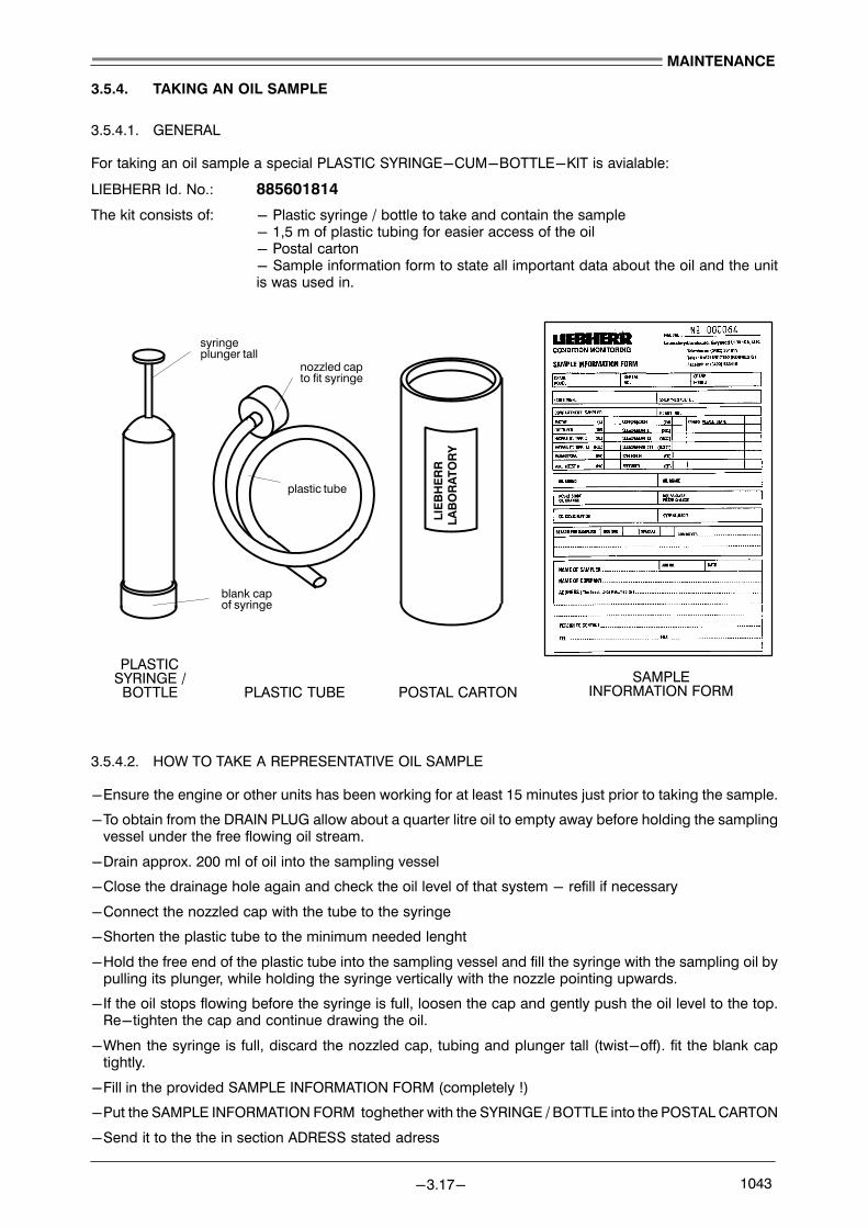
LIEBHERR
LABORATO
RY
PLASTICSYRINGE /BOTTLE PLASTIC TUBE POSTAL CARTON
syringeplunger tall
nozzled capto fit syringe
plastic tube
blank capof syringe
SAMPLEINFORMATION FORM
MAINTENANCE
−3.17− 1043
3.5.4. TAKING AN OIL SAMPLE
3.5.4.1. GENERAL
For taking an oil sample a special PLASTIC SYRINGE−CUM−BOTTLE−KIT is avialable:
LIEBHERR Id. No.: 885601814
The kit consists of: − Plastic syringe / bottle to take and contain the sample− 1,5 m of plastic tubing for easier access of the oil− Postal carton− Sample information form to state all important data about the oil and the unitis was used in.
3.5.4.2. HOW TO TAKE A REPRESENTATIVE OIL SAMPLE
−Ensure the engine or other units has been working for at least 15 minutes just prior to taking the sample.
−To obtain from the DRAIN PLUG allow about a quarter litre oil to empty away before holding the samplingvessel under the free flowing oil stream.
−Drain approx. 200 ml of oil into the sampling vessel
−Close the drainage hole again and check the oil level of that system − refill if necessary
−Connect the nozzled cap with the tube to the syringe
−Shorten the plastic tube to the minimum needed lenght
−Hold the free end of the plastic tube into the sampling vessel and fill the syringe with the sampling oil bypulling its plunger, while holding the syringe vertically with the nozzle pointing upwards.
−If the oil stops flowing before the syringe is full, loosen the cap and gently push the oil level to the top.Re−tighten the cap and continue drawing the oil.
−When the syringe is full, discard the nozzled cap, tubing and plunger tall (twist−off). fit the blank captightly.
−Fill in the provided SAMPLE INFORMATION FORM (completely !)
−Put the SAMPLE INFORMATION FORM toghether with the SYRINGE / BOTTLE into the POSTAL CARTON
−Send it to the the in section ADRESS stated adress

HYDRAULIC OIL TANK SLEWING GEAR
HOISTING WINCH
SYRINGE
SAMPLING VESSEL
SAMPLING VESSEL
SYRINGE
SYRINGE
MAINTENANCE
−3.18− 1043
3.5.4.3. SAMPLING POINTS (EXAMPLES)
3.5.4.4. POST ADDRESS
LABORATORY: LLANDUDNOGWYNEDD LL30 1SAUNITED KINGDOM
3.5.5. CONDITION MONITORING REPORT
The results of the oil sample examination are all stated in the CONDITION MONITORING REPORT whichis sent to the in the SAMPLE INFORMATION FORM stated address. In this report a diagnosis of the oil sampleis given as well as a advice for further action.
Four different symbols are indicated to signalize the main action:
INDICATES Normal
INDICATES High result reading obtained, submit second sample for recheck
INDICATES Change oil as indicated
INDICATES Action required as indicated
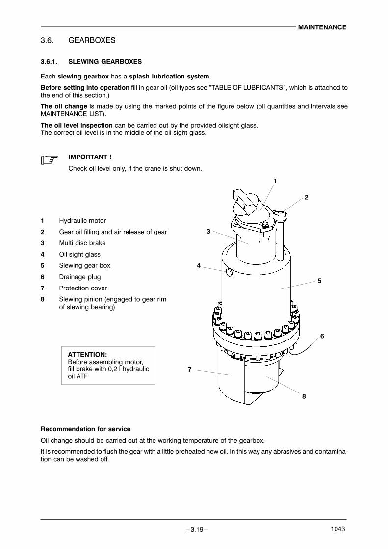
1
4
8
6
5
2
3
7
ATTENTION:Before assembling motor,fill brake with 0,2 l hydraulic oil ATF
MAINTENANCE
−3.19− 1043
3.6. GEARBOXES
3.6.1. SLEWING GEARBOXES
Each slewing gearbox has a splash lubrication system.
Before setting into operation fill in gear oil (oil types see "TABLE OF LUBRICANTS", which is attached tothe end of this section.)
The oil change is made by using the marked points of the figure below (oil quantities and intervals seeMAINTENANCE LIST).
The oil level inspection can be carried out by the provided oilsight glass.The correct oil level is in the middle of the oil sight glass.
. IMPORTANT !
Check oil level only, if the crane is shut down.
1 Hydraulic motor
2 Gear oil filling and air release of gear
3 Multi disc brake
4 Oil sight glass
5 Slewing gear box
6 Drainage plug
7 Protection cover
8 Slewing pinion (engaged to gear rimof slewing bearing)
Recommendation for service
Oil change should be carried out at the working temperature of the gearbox.
It is recommended to flush the gear with a little preheated new oil. In this way any abrasives and contamina�tion can be washed off.

3
2
4
5
1
6
MAINTENANCE
−3.20− 1043
3.6.2. HOIST WINCH GEARBOX
There is one main winch gearbox used in the crane.
It has a splash lubrication system.
Before setting into operation fill in gear oil (oil types see "TABLE OF LUBRICANTS", which is attached tothe end of this section.)
The oil change is made by using the marked points of the figure below.(oil quantities and intervals seeMAINTENANCE LIST)
Remove the breather plug when exchanging the oil, but don’t forget to put it on again after the oil exchange.
The oil level inspection can be carried out by the provided dip stick on the side of the winch drum. For theinspection do screw−in dipstick.
. NOTE !
The MAXIMUM OIL LEVEL in a winch gearbox should be up to center line only, however checkfor correct level with provided DIPSTICK. Check oil level only, if the crane is shut down.
LAYOUT OF WINCH:
1 Rope drum2 Air breather3 Dipstick and gear oil filling4 Winch frame5 Gearoil drainage6 Flange for hydr. motores
Recommendation for service
Oil change should be carried out at the working temperature of the gearbox.
It is recommended to flush the gear with a little preheated new oil. In this way any abrasives and contamina�tion can be washed off.

Ropedrum
Ropekicker
Detail 2Detail 1
MAINTENANCE
−3.21− 1043
ROPE KICKER (DEFLECTOR):
. NOTE !
Following maintenance works must be performed every 500 operations hours or every threemonths.
− Check wear and if neccessary remove chaffing from rope kicker
− Check if screws are in counter sunk position (Detail 1)
In case of excessive wear exchange rope kicker to avoid damages of the hoisting rope
. NOTE !
When mounting new rope kicker check, if in correct alignment (Detail 2)

12
11
1
10
2
9
8
7
6
3
4
5
4
ÉÉÉÉÇÇÇ
ÇÇÇÇÇÇÇÇÇ
ÉÉÉÉÉÉÉÉ
ÇÇÇÇÇÇÇÇ
ÇÇÇÇ
ÇÇÇÇ
ÇÇÇÇ
ÉÉÉÉÉÉÉÉÉÉÇÇÇÇÇÇÇÇÇÇÇÇ
ÇÇÉÉÉÉÇÇÉÉÇÇÉÉÇÇÉÉÇÇÇÇÉÉÇÇÉÉÇÇÉÉÇÇ
ÇÇÉÉÉÉÉÉÇÇÉÉÉÇÇÉÉÉÇÇÉÉÉÇÇÇÇÉÉÉÇÇÉÉÉÇÇÉÉÉÇÇ
45
3
1112
8
HYDRAULIC MOTOR
GEAR−BOX
1 2
MAINTENANCE
−3.22− 1043
3.7. MULTIPLE DISC BRAKES
GENERAL:
The spring loaded multiple disc brakes on our machines are used as HOLDING BRAKES ONLY, as the slowdown of any movement is done by the hydraulic system. Therfore they are subject to very little wear. Thebrakes are only on high wear, in the case of an EMERGENCY STOP SITUATION with full load. In this casethe mulitple disc brake of the winch(es) must be inspected and checked for proper function.
The maximum holding moment of a respective machine or drive is determined by the various arrangementsof the disks and springs in these brakes.
WARNING !For this reason, the arrangement and layout of the multi−disc−brake mustalways be exact and special caution must always be exercised, when re�pairs are carried out or when brakes are replaced. Only an exact arrange�ment protects the drives from overloading as well as guaranteeing the maxi�mum holding moment !
THE PROPER ARRANGEMENT OF THE DISCS AND SPRINGS IN THE BRAKES FOR THE WINCHESAS WELL AS FOR THE SLEWING GEAR ARE SHOWN IN THE CROSS SECTION DRAWINGS IN THESPARE − PARTS − LIST OF THIS CRANE !
PRINCIPLE BRAKE LAYOUT:
1 Piston
2 Housing
3 Hydraulic pressure connection
4 Brake disc with outer gear rim (AL)
5 Brake disc with inner gear rim (IL)
6 Discs bracket
7 Leak oil connection
8 Friction faces (RFL)
9 Outer seal
10 Inner seal
11 Outer spring for brake force (AF)
12 Inner spring for brake force (IF)
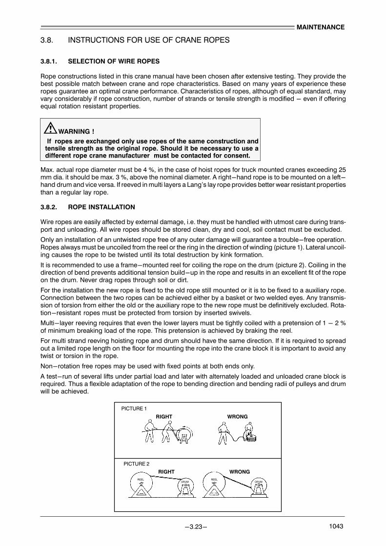
PICTURE 1
PICTURE 2
RIGHT WRONG
REELDRUM
REELDRUM
RIGHT WRONG
MAINTENANCE
−3.23− 1043
3.8. INSTRUCTIONS FOR USE OF CRANE ROPES
3.8.1. SELECTION OF WIRE ROPES
Rope constructions listed in this crane manual have been chosen after extensive testing. They provide thebest possible match between crane and rope characteristics. Based on many years of experience theseropes guarantee an optimal crane performance. Characteristics of ropes, although of equal standard, mayvary considerably if rope construction, number of strands or tensile strength is modified − even if offeringequal rotation resistant properties.
WARNING ! If ropes are exchanged only use ropes of the same construction andtensile strength as the original rope. Should it be necessary to use adifferent rope crane manufacturer must be contacted for consent.
Max. actual rope diameter must be 4 %, in the case of hoist ropes for truck mounted cranes exceeding 25mm dia. it should be max. 3 %, above the nominal diameter. A right−hand rope is to be mounted on a left−hand drum and vice versa. If reeved in multi layers a Lang’s lay rope provides better wear resistant propertiesthan a regular lay rope.
3.8.2. ROPE INSTALLATION
Wire ropes are easily affected by external damage, i.e. they must be handled with utmost care during trans�port and unloading. All wire ropes should be stored clean, dry and cool, soil contact must be excluded.
Only an installation of an untwisted rope free of any outer damage will guarantee a trouble−free operation.Ropes always must be uncoiled from the reel or the ring in the direction of winding (picture 1). Lateral uncoil�ing causes the rope to be twisted until its total destruction by kink formation.
It is recommended to use a frame−mounted reel for coiling the rope on the drum (picture 2). Coiling in thedirection of bend prevents additional tension build−up in the rope and results in an excellent fit of the ropeon the drum. Never drag ropes through soil or dirt.
For the installation the new rope is fixed to the old rope still mounted or it is to be fixed to a auxiliary rope.Connection between the two ropes can be achieved either by a basket or two welded eyes. Any transmis�sion of torsion from either the old or the auxiliary rope to the new rope must be definitively excluded. Rota�tion−resistant ropes must be protected from torsion by inserted swivels.
Multi−layer reeving requires that even the lower layers must be tightly coiled with a pretension of 1 − 2 %of minimum breaking load of the rope. This pretension is achieved by braking the reel.
For multi strand reeving hoisting rope and drum should have the same direction. If it is required to spreadout a limited rope length on the floor for mounting the rope into the crane block it is important to avoid anytwist or torsion in the rope.
Non−rotation free ropes may be used with fixed points at both ends only.
A test−run of several lifts under partial load and later with alternately loaded and unloaded crane block isrequired. Thus a flexible adaptation of the rope to bending direction and bending radii of pulleys and drumwill be achieved.

MAINTENANCE
−3.24− 1043
3.8.3. MAINTENANCE
Maintenance at regular intervals guarantees safe crane operation and considerably increases rope life. Wireropes must be regreased at regular intervals according to crane operation, this especially applies to thebending zones at the drums and pulleys. When exposed to the same test condition a well−greased ropehas shown four times as many working cycles than an ungreased rope. Relubricants must be compatiblewith the original lubricant used.
The following lubricants are recommended:
All standard lubricants recommended by the crane manufacturer for open gears Special lubricants like e.g.:Texaco Novatex Grease EP2, Rocol RD 105, Aral Aralub LFZ1
For ropes being reeved in multiple layers and therefore being exposed to extreme wear use of graph�ite containing lubricants is recommended like e.g.: Reiner Ceplattyn KG 10, Texaco Novatex FK 10
Heavily soiled wire ropes have to be cleaned regularly with a brush. If the lower layers on the drum are sel�domly used or not used at all, ropes have to be unreeled from time to time and then have to be reinstalledunder prestress. A rope operates most economical when used in its whole length. Therefore it is recom�mended to always use the appropriate rope length according to crane operation; this is mainly true if craneis operated continously for a long period of time.
If a rope is unequally loaded it may be reversed. The formerly free end is fixed in the drum by positioningunworn zones at zones mostly exposed to wear thus rope life can be extended considerably.
If wear mainly occurs if rope is multi−layer reeved on the Lebus drum, rope life may be increased by cut�ting−off one length according to 1/3 of drum circumference. This procedure can be repeated up to threetimes per rope.
3.8.4. INSPECTION
Wire ropes have been dimensioned to provide sufficient safety margins after the occurence of first signs ofa wire breakage before a replacement of the rope is required. The ropes have to be inspected in regularintervals; especially in the time period following directly after its installation. In addition special attention isrequired if a rope has been exposed to excessive wear, if non−visible damage is supected or if there areother indications for rope damage.
The following criteria for a safe operation of the ropes can be applied:− type and number of wire breakages (see table)− position and time sequence of the wire breakages− decrease of rope diameter− corrosion, abrasion, deformation− heat−effects − length of period of running
First signs of a change in rope behaviour must be carefully monitored.
ATTENTION !A twisting and waving of strands above the crane block can be an in�dication for a severly damaged rope. This twisting/waving is caused al�ways by an additional torsion in the rotation−resistant hoisting ropeoriginating from a number of adverse effects but may also be due toan overstretching of the hoist rope during heavy duty operation or dueto shockloads resp. tearing on sticky container in hold. The torsion hasto be untwisted at the rope fixpoint and requires extreme care and re�spective know−how. Therefore inspection is necessary at regular in�tervals especially shortly after the new rope has been installed.
Untwisting of crane pulley block with rotation−stable rope fixed point: − Set down of pulley block − Determine direction of twist. − Detach rope from fixpoint and turn rope at the end approx. 180 − 360° into the direction which compen− sates the twisting resp. waving of the rope.− Connect rope at fixpoint and carefully lift pulley block, operate crane unloaded with pulley block and also with crane trolley if present− Repeat if necessary

MAINTENANCE
−3.25− 1043
. IMPORTANT !
Make sure that twist is distributed to a long free rope end. By operating the crane in unloaded con�dition twist is to be distributed to the entire rope length. By operating the crane in unloaded condi�tion twist is to be distributed to the entire rope length. By no means forcefully twist a short lengthof rope; this may permanently damage rope structure.
If the hoisting rope was operated with open swivel an untwisting can be achieved by operating the trolleyseveral times under no load conditions and with unloaded hook. If not successful, follow same proceduregiven for ropes with fixed point, e.g. if crane does not provide of a swivel, if rope is predamaged or if causesof twist can not be remedied otherwise. At the same time a regular check of all rope end terminations andsuspensions for proper function is required. Individual components of rope drive unit, drums and pulleysmust turn freely in their bearings. Grooves should not show any rope marks. Minimum groove radius ondrums and pulleys should be 0,53 x nominal rope diameter.
3.8.5. INSTRUCTIONS FOR UNTWISTING OF HOIST ROPES
1) Twisting of a multi−reeved crane block may be due to a number of causes. Any faults in the rope drivemust be eliminated, the load/stretch torsion will "seat in" after some time of rope operation.
2) If a hoist rope is operated with open swivel an untwisting by several runs with unloaded hook will be suffi�cient in most cases. If this procedure prooves to be ineffective refer to the instructions given for compensa�tion of twist for ropes with rotation− stable fixed point, e.g. − if no swivel is provided
− if the rope is predamaged or− if the causes of the twist can’t be eliminated.
3) Determination of direction of twistAt first the direction of the twist of the crane pulley block must be determined. Pictures 1 and 2 show a pos�sible twist of a right hand lay rope, on picture 3 + 4 of a left hand lay rope. In the right hand corner of eachpicture a sketch shows the occurence of multiple twist. The respective direction of twist is indicated by acontinously drawn arrow printed in boldface. If it is difficult to identify the direction of twist for large hoistingheights turn rope in direction of arrow with dashed line once thus eliminating "braid". For compensation turnrope end shown separately in the direction of the continous arrow. It is important that the correct referencepoint is selected i.e. the crane operator must hold the rope in front of himself.
The direction of untwist can be determined also by simulating this situation by simply using a string.
4) Untwisting of crane pulley block with rotation−stable rope fixed point:− Set down of pulley block− Determine direction of twist− Detach rope at fixed point− Carefully turn rope at free end of at least 15 m length up to max. 180 − 360 degrees to compensate pulley block twist− Reattach rope at the fixed point− Carefully lift pulley block and operate unloaded crane with pulley block and jib − Repeat if necessary
. IMPORTANT !
Make sure that twist is distributed to a long free rope end. By operating the crane in unloaded con�dition twist is to be distributed to the entire rope length. By no means forcefully twist a short lengthof rope; this may permanently damage rope structure.

Picture 1
Picture 2
Picture 3
Picture 4
Picture 5
Picture 6
Picture 8 Picture 7
MAINTENANCE
−3.26− 1043
3.8.6. DISCARD CRITERIA
Warning for safety reasons crane ropes haveto be discarded if showing one of the followingcriteria:
− Break of one strand− Accumulation of wire breaks− Number of wire breaks as defined in table − Corkscrew−type deformations of more than 1/3 rope diameter (pict. 1)− Basketlike distortions − Hair−pin type extrusion of wire or groups of wire (pict. 3)− Decrease of rope diameter by 15 % against nominal diameter of rope or − by 10 % if there are signs of corrosion and / or abrasion (pict. 4)− Loosening of rope structure (pict. 4)− Local decrease of rope diameter (pict. 5)− Bends and local crushing (pict. 6 + 8)− Kinks or resulting permanent deformations (pict. 7)
If special rope damage is found, the cause has tobe determined and eliminated before a new ropewill be installed. Damage or stress markings atcrane components provide valuable informationfor possible causes of rope damage.
If in doubt discard rope or consult expert for fur�ther assistance.

MAINTENANCE
−3.27− 1043
3.9. REPLACEMENT OF ROPES
3.9.1. REEVING HOIST GEARSee also drawing REEVING PLAN in section DRAWINGS.
. IMPORTANT !
ONLY QUALIFIED AND AUTHORIZED SERVICE PERSONS ARE ALLOWED TO PERFORMMAINTENANCE OR SERVICE TO THE CRANE !
. IMPORTANT !
PRIOR STARTING TO REPLACE THE ROPES READ CAREFULLY SECTION �INSTRUCTIONSFOR USE OF CRANE ROPES" (INSTALLATION, MAINTENANCE, INSPECTION, ETC.).ALWAYS LOWER THE JIB INTO ITS REST POSITION FOR SAFETY REASONS !
− Always use adequate safety equipment (safety boots, safety gloves, hard hat)
− Disconnect auxiliary devices and lower the jib into its rest position
− It is advisable to discard the old rope first and install the new one afterwards
− Put lower hook block on deck and secure hoisting rope at rope fix point 1.
− Sufficient slack rope is required to allow disconnecting the rope from rope fix point 1.
− Use an auxilliary rope to lower hoisting rope to deck and then disconnrct the lower hook block
− Drive hoisting winch in direction lowering until lower limit switch tripped to pull off the old rope to thefront (sufficient space is required). Watch the rope on the drum.
− Bypass now the lower limit switch �lowering".
. IMPORTANT !
BYPASSING OF SAFETY DEVICES ( LIMIT SWITCHES, ETC. ) FOR SERVICE PURPOSES ONLYTO BE PERFORMED BY QUALIFIED AND TRAINED PERSONAL !
− Continue spooling off the old rope until rope fix point 2
− Secure the rope at rope fix point 2
− Release hoisting rope from rope fix point 2 and connect a cable pulling strap (chinese fingers) on therope
− Connect an auxiliary standard ’nylon rope’ of adequate strength and length to the cable pulling strap
− Pull off the old hoisting rope to the front
− Disconnect the old rope from the cable pulling strap and connect new rope instead
− Use the auxiliary rope (nylon rope) and the pulling strap again to pull the new wire rope correctly intothe system.
. NOTE !
Any transmission of torsion from the auxiliary rope to the new rope must be definitively excluded.Rotation−resistant ropes must be protected from torsion by inserted swivels.
− Secure the rope next to the drum
− Connect the new rope to the rope fix points 1 and 2, pull the rope onto the drum till three (3) safetywindings are on the drum, adjust (check) limit switch �lowering".
− First a test−run of several lifts under unloaded load and partial load is required. Thus a flexibleadaptation of the rope to bending direction and bending radii of pulleys and drum will be achieved.Check correct adjustments and function of all limit switches and all rope protection devices !
. IMPORTANT !
CHECK ALL SAFTY DEVICES AND LIMIT SWITCHES AFTER EACH REPLACEMENT OF ROPES!

Rope, righthanded, Ø 25 mm, l = 280 m
Hoisting winch
Rope fix point 1
Rope fix point 2
Tighening torque: 210 NmBolt grade: M16 8.8
Thread greased, use no molykoteor graphitized greases !
MAINTENANCE
−3.28− 1043
3.9.1.1. LAYOUT OF ROPE REEVING
3.9.1.2. ROPE FIX POINT 2 AT HOISTING WINCH DRUM
. IMPORTANT !
AFTER THE FIRST TEST−RUN OF SEVERAL LIFTS CHECK ROPE FIX POINTS, ROPE PULLEYSAND ROPE PROTECTION DEVICES AGAIN !
. NOTE !
SHOULD YOU HAVE ANY QUESTIONS RELATING TO OPERATION, SERVICE, REPAIRS OR PARTS OF THE WINCH SYSTEM INSTALLED ON YOUR CRANE, PLEASE CONTACT THE LIEBHERR CUSTOMER SERVICE.
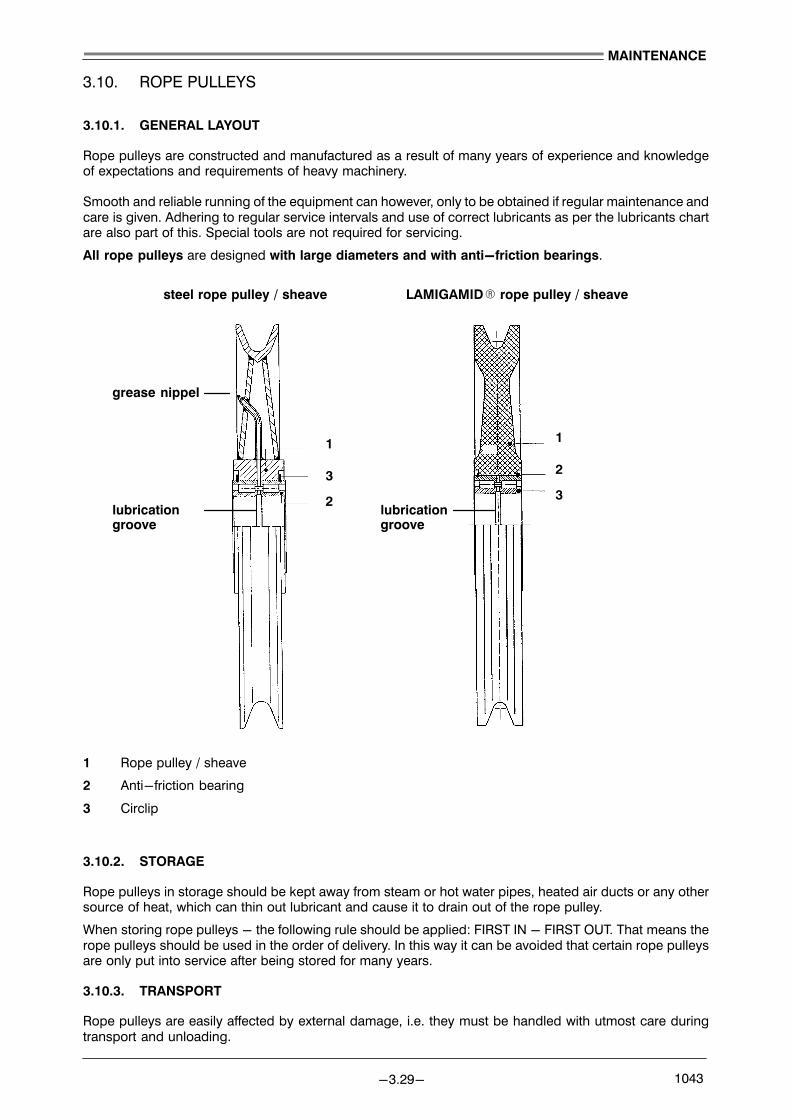
1
2
3
1
2
3
LAMIGAMIDR rope pulley / sheavesteel rope pulley / sheave
grease nippel
lubricationgroove
lubricationgroove
MAINTENANCE
−3.29− 1043
3.10. ROPE PULLEYS
3.10.1. GENERAL LAYOUT
Rope pulleys are constructed and manufactured as a result of many years of experience and knowledgeof expectations and requirements of heavy machinery.
Smooth and reliable running of the equipment can however, only to be obtained if regular maintenance andcare is given. Adhering to regular service intervals and use of correct lubricants as per the lubricants chartare also part of this. Special tools are not required for servicing.
All rope pulleys are designed with large diameters and with anti−friction bearings.
1 Rope pulley / sheave
2 Anti−friction bearing
3 Circlip
3.10.2. STORAGE
Rope pulleys in storage should be kept away from steam or hot water pipes, heated air ducts or any othersource of heat, which can thin out lubricant and cause it to drain out of the rope pulley.
When storing rope pulleys − the following rule should be applied: FIRST IN − FIRST OUT. That means therope pulleys should be used in the order of delivery. In this way it can be avoided that certain rope pulleysare only put into service after being stored for many years.
3.10.3. TRANSPORT
Rope pulleys are easily affected by external damage, i.e. they must be handled with utmost care duringtransport and unloading.
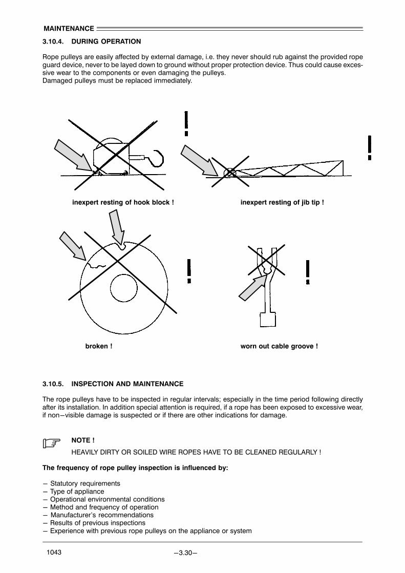
inexpert resting of hook block ! inexpert resting of jib tip !
broken ! worn out cable groove !
MAINTENANCE
−3.30− 1043
3.10.4. DURING OPERATION
Rope pulleys are easily affected by external damage, i.e. they never should rub against the provided ropeguard device, never to be layed down to ground without proper protection device. Thus could cause exces�sive wear to the components or even damaging the pulleys.Damaged pulleys must be replaced immediately.
3.10.5. INSPECTION AND MAINTENANCE
The rope pulleys have to be inspected in regular intervals; especially in the time period following directlyafter its installation. In addition special attention is required, if a rope has been exposed to excessive wear,if non−visible damage is suspected or if there are other indications for damage.
. NOTE !
HEAVILY DIRTY OR SOILED WIRE ROPES HAVE TO BE CLEANED REGULARLY !
The frequency of rope pulley inspection is influenced by:
− Statutory requirements− Type of appliance − Operational environmental conditions− Method and frequency of operation− Manufacturer’s recommendations− Results of previous inspections− Experience with previous rope pulleys on the appliance or system
MAINTENANCE
−3.31− 1043
Service intervals:
Smooth and reliable running of the equipment can however, only to be obtained if regular maintenance andcare is given. Adhering to regular service intervals and use of correct lubricants as per the lubricants chartare also part of this. Special tools are not required for servicing.
ANTI −FRICTION BEARINGS OF the rope pulleys must be regreased at regular intervals according to craneoperation. Individual components of rope pulleys must turn freely in their bearings.
GROOVES should not show any rope marks.
At the same time a REGULAR CHECK OF THE ROPES for proper function, cleanless and sufficient lubrica�tion is required.
. NOTE !
AFTER FIRST 100 HRS ALL PULLEYS HAVE TO BE CHECKED FOR SMOOTH AND RELIABLERUNNING, CORRECT FIT OF ROPE PROTECTION AND OTHER SECURING DEVICES.
THE MINIMUM REQUIREMENT FOR MAINTENANCE / CHECK UP IS EVERY 500 HRS, IF THECRANE IS NOT OPERATED AT LEAST TWICE PER YEAR FOR ANY MECHANICAL DAMAGES,LUBRICATION CONNECTIONS AND CONDITION.
. NOTE !
ENSURE THAT THE GREASE DOES ESCAPE FROM / BETWEEN THE ROPE PULLEYS AT LEASTEVERY 500 WORKING HOURS.
. NOTE !
CHECK THE WEAR OF THE ROPE GROOVE, FIRST SIGNS OF A CHANGE IN THE ROPE’SBEHAVIOR OR THE PULLEY ITSELF MUST BE CAREFULLY MONITORED !
CHECK THE PULLEYS GROOVE PROFILE AT LEAST EVERY 500 WORKING HOURS.
At this point we also do recommend to study carefully the �INSTRUCTIONS FOR USE OF CRANE ROPES".
3.10.6. RESISTANCE TO CHEMICAL PRODUCTS OF LAMIGAMIDR ROPE PULLEYS
For cleaning of LAMIGAMIDR rope pulleys various benzin may be used. However, the PULLEYS SHOULDNOT BE CLEANED OR GET IN TOUCH WITH THE FOLLOWING CHEMICALS OR CHEMICAL COM�POUNDS:
RESISTANT FOR
− Petroleum, benzin, kerosin, diesel fuel
LIMITED RESISTANT
− alcohol except ethyl−, methyl− and propyl alcohol− anorganic chlorides, such as calcium, lithium−, magnesium− and zincchloride
NOT RESISTANT AGAINST
− concentrated mineral acids (i.e. sulphuric acid, hydrochlorid acid, nitric acid)− concentrated organic acids (i.e. formic acid)− concentrated alkalines (i.e. sodium, potash lye or caustic potash)− phenolic resin, phenolic plastic

3
1
2
4
Pretensioning load: 665 KN
Pretensioning acc. to working−instruction: QSA 09.601.00−xx
Pretension jacking tool: LWN 2−17−038 Idt.−No. 519625814
7
5
6
Sealed with SIKAFLEX all around
MAINTENANCE
−3.32− 1043
3.11. ROLLER SLEWING RING
The roller slewing ring connects the base column with the crane. It is equipped with hardened roller tracksand absorbes all vertical and horizontal forces as well as the tilt moment occuring during operation. The ringis attached by means of high tensile bolts. The pretension load for these bolts is shown on the sketch below.
The gear ring and the slewing pinion, which engages with the slewing ring are housed within the crane su�perstructure and protected against seewater.
1 Steel structure of slewing column2 Outer bolt3 Roller slewing bearing. Grease every 100 working hours4 Protection cap (filled with grease)5 Inner bolt6 Grease nipple of roller slewing ring7 Gear rim of roller slewing ring. Keep greased all the time !
. IMPORTANT !
Gear rim (Pos 7): to be greased, we recommend to use GREASE SP−F AVIA ALUPLEX 2 RHY
. IMPORTANT !
Bolts (Pos 2+5): thread greased, use no MOLYCOTES or GRAPHITIZED GREASES !

MAINTENANCE
−3.33− 1043
3.12. ELECTRICAL SYSTEM
3.12.1. MAINTENANCE TO THE ELECTRICAL SYSTEM
Maintenance of the electrical system is largely restricted to changing fuses and bulbs, if blown and cleaningthe filters on the switch cabinet. The filter on the switch cabinet fan should be renewed or cleaned approxi�mately every 3000 working hours.
. NOTE !
CLEAN DUST FILTERS ON THE SWITCH CABINETS EVERY 3000 OPERATING HOURS. RE�PLACE DAMAGED OR CONTAMINATED FILTERS IMMEDIATELY.
. NOTE !
BLOWN FUSES OR INDICATION LAMPS HAVE TO BE REPLACED IMMEDIATELY.
All screws and bolts used for or with electrical equipment should be retightened in regular intervals. (seeMAINTENANCE LIST)
ATTENTION !ALL ELECTRIC SAFETY EQUIPMENT (E.G LIMIT SWITCHES, EMER�GENCY STOP BUTTONS ETC.) SHOULD BE CHECKED IN REGULAR IN�TERVALS AS WELL TO ENSURE A SAFE OPERATION OF THE CRANE.(SEE MAINTENANCE LIST)
WARNING !BEFORE OPENING ANY ELECTRIC EQUIPMENT, it is essential toSWITCH OFF THE POWER SUPPLY.
3.12.2. WET CLEANING
Wet cleaning of the switch box or switch gear is not allowed !
When washing or steam cleaning the crane or components − close all terminal− and switch boxes in orderto prevent water from entering !

MAINTENANCE
−3.34− 1043
3.13. MAINTENANCE INSTRUCTIONS FOR SLIP RING UNIT
The slip ring is installed between SLEWING COLUMN and the PEDESTAL ADAPTOR.
. NOTE ! ONLY QUALIFIED AND AUTHORIZED SERVICE PERSONS ARE ALLOWED
TO PERFORM MAINTENANCE OR SERVICE TO THE SYSTEM !
3.13.1. TERMINAL BOX
Every 500 hours a tightness test of a random sample of the terminal clamp screws should be carried out.
3.13.2. POWER SECTION
Due to the low turning speed and the hardness of carbon brushes, the brushes have a relatively long life.They must be checked every 1500 hours or latest every 6 months, and must be changed in good timeso that it never happens that a metal part of the brush holder touches the slip ring.
During this check it is also necessary to clean any carbon dust from the insulating barriers between the slip�ring ways so as to avoid creeping current. Every 500 hours a random sample of the screw connectionsof the copper bus bars should be checked for tightness.
3.13.3. SIGNAL SECTION
The 16 Amp. circuits are fitted with nickel plated and gold plated copper−beryllium wire brushes and withnickel plated and gold plated sliprings. About every 1000 hours or latest every 6 months the insulatingbarriers between the slip−ring ways should be cleaned of metal particles.
To reduce wear the slip−ring ways should be lightly sprayed with a contact oil such as �Cramolin B".A random sample of the terminal screws for the terminals of the cables from the copper−beryllium wirebrushes should be checked for tightness.
The carbon brush blocks must be checked according to point 2 mentioned above.
3.13.4. CABLE INSULATION
The cables have to be checked for any damages in insulation when carrying out an inspection.
When cables connected to the slipring or have to be replaced always asure that the insulation to be keptas short as possible.
. NOTE !
SHOULD YOU HAVE ANY QUESTIONS RELATING TO OPERATION, SERVICE, REPAIRS OR PARTS FOR THE SLIP RING INSTALLED ON THE CRANE, PLEASE CONTACT THE LIEBHERR CUSTOMER SERVICE.
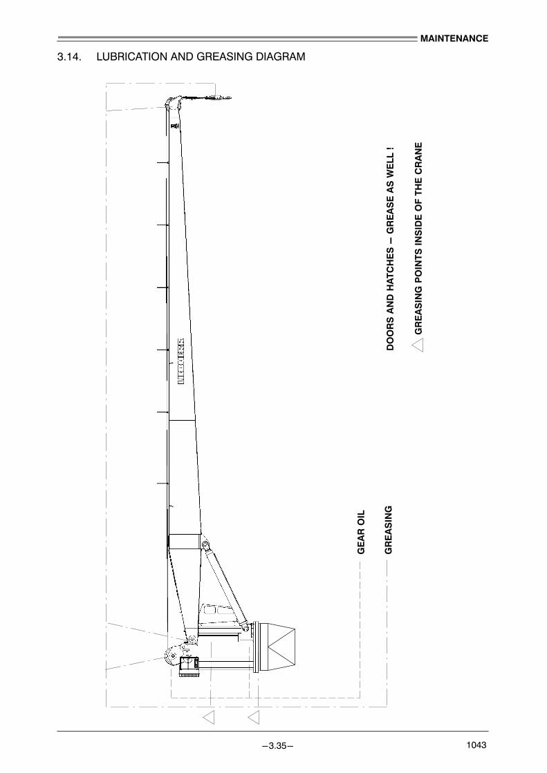
DOORS A
ND H
ATC
HES −
GREASE AS W
ELL
!
GEAR O
IL
GREASIN
G
GREASIN
G POIN
TS INSID
E O
F TH
E C
RANE
MAINTENANCE
−3.35− 1043
3.14. LUBRICATION AND GREASING DIAGRAM

MAINTENANCE
−3.36− 1043

Maintenance / Service shall be supervised by LIEBHERR SERVICE TECHNICIAN
Maintenance / Service shall be carried out by LIEBHERR SERVICE TECHNICIAN
operating hours counter (switch box X1)
MAINTENANCE
−3.37− 1043
3.15. MAINTENANCE LISTS
3.15.1. GENERAL INFORMATION
The maintenance intervals mentioned in this section are guiding times and should be observed.
If due to extreme environmental conditions (i.e. dust, tropical conditions) or extreme operational conditions(i.e. multiple shift operation) a deviation to the given maintenance interval(s) should become necessary, askyour local LIEBHERR CUSTOMER SERVICE for advice and confirmation to do so.
. NOTE !
IT SHOULD BE NOTED THAT IN PARTICULAR THE MAINTENANCE TIME INTERVALSINDICATED ARE APPROXIMATE. IN REALITY THESE INTERVALS SHOULD DEPENDON CRANE USAGE AND THEREFORE − MAY NEED TO BE UPDATED ACCORDINGLY.
. IMPORTANT !
The maintenance intervals indicated in the maintenance list are based on the ACTUAL OPERATING HOURS OF THE CRANE. Should the crane be standing for a period ofmore then four ( 4 ) weeks − the crane has to be operated ONCE A MONTH FOR AT LEASTTWO ( 2 ) HOURS. In addition to that all the greasing, oil inspections and oil level checks haveto be done as well.
3.15.2. OVERVIEW MAINTENANCE INTERVALS
FIRST 100 HRS resp. AFTER 2 WEEKS
FIRST 500 HRS resp. AFTER 10 WEEKS
FIRST 1000 HRS resp. AFTER 6 MONTHS
EVERY 10 HRS resp. DAILY
EVERY 50 HRS resp. WEEKLY
EVERY 500 HRS resp. EVERY 3 MONTHS
EVERY 2000 HRS resp. EVERY YEAR
3.15.2.1. DISPOSAL OF USED MATERIALS
DISPOSAL ! When changing oil, grease, filter elements, batteries, etc. − used materials must be properlydisposed of in accordance with the relevant state regulations.Contamination of soil, sewage and water systems must be avoided !

FILLINGQUANTITIES, appr.
HYDR. O
IL TANK
HOISTING W
INCH
SLE
WIN
G G
EAR BOXES
GEAR RIM
SLE
WIN
G RIN
G
GREASIN
G POIN
TS
ROPES
SYSTEM
Type of OIL
GREASE
1050
l
6 l
3 x 11
,2 l
− − −
ATF or simular
SAE, HDC or sim.
AVIALITH 2EP
SP−F AVIAALUPLEX 2
Ca.−grease EP
( liter )
... OIL ...GREASE
MAINTENANCE
−3.38− 1043
3.15.2.2. QUALIFIED PERSONS
PERSONS RESPONSIBLE FOR THE SAFETY OF THE CRANE MUST ENSURE THAT:
− qualified persons are only delegated to work on the machinery or apparatus,
− these persons must keep the Operating− and Maintenance Instructions provided, and other documents,available when carrying out the operations to which they refer and to follow that documentation without fail,− unauthorised persons are prohibited from working on, or approaching, the machinery or apparatus.
Qualified persons are persons who, as a result of their training, experience and the instruction they havereceived, and of their knowledge of the relevant Standards, directives, accident prevention regulations andoperating conditions, have been authorised by those responsible for the safety of the machine to carry outthe particular task required and who are able to recognise and avoid the potential hazards. A knowledgeof first−aid and local rescue equipment is essential. According to regulations, unqualified personnel areforbidden to work for example on power installations and apparatus.
3.15.3. FILLING QUANTITIES
. NOTE !
See also details provided in section MAINTENANCE for each individual function group and TABLE OF LUBRICANTS !
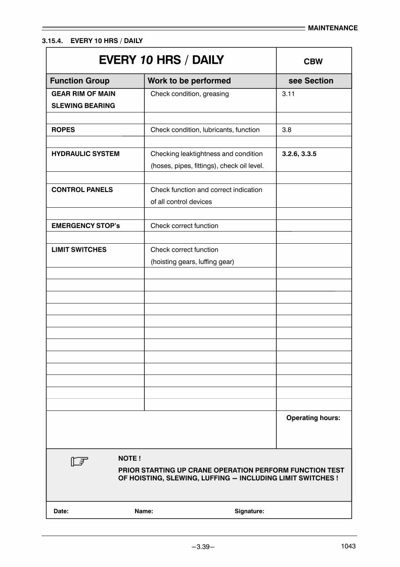
Date:
Function Group Work to be performed see Section
Signature:
CBW
Operating hours:
Name:
EVERY 10 HRS / DAILY
MAINTENANCE
−3.39− 1043
3.15.4. EVERY 10 HRS / DAILY
GEAR RIM OF MAIN Check condition, greasing 3.11
SLEWING BEARING
ROPES Check condition, lubricants, function 3.8
HYDRAULIC SYSTEM Checking leaktightness and condition 3.2.6, 3.3.5
(hoses, pipes, fittings), check oil level.
CONTROL PANELS Check function and correct indication
of all control devices
EMERGENCY STOP’s Check correct function
LIMIT SWITCHES Check correct function
(hoisting gears, luffing gear)
. NOTE !
PRIOR STARTING UP CRANE OPERATION PERFORM FUNCTION TESTOF HOISTING, SLEWING, LUFFING − INCLUDING LIMIT SWITCHES !

MAINTENANCE
−3.40− 1043

Date:
Function Group Work to be performed see Section
Signature:
CBW
Operating hours:
Name:
EVERY 50 HRS / WEEKLY
MAINTENANCE
−3.41− 1043
3.15.5. EVERY 50 HRS / WEEKLY
CRANE COMPLETE Visual check of all greasing lines, 3.1, 3.2, 3.14
greasing points, regrease as required
HOISTING WINCH Check gear oil level, grease counter− 3.6.2
bearing
SLEWING GEAR BOXES Check gear oil level 3.6.1
MAIN SENSORS Check cables and plug connection
(pressure−, temperature− and level
sensors)
ROPES Check condition and rope fix−points 3.8
. NOTE !
WHEN REGREASING − STOP GREASING SOON AS NEW GREASE APPEARS FROM SEALINGS.

MAINTENANCE
−3.42− 1043

Date:
Function Group Work to be performed see Section
Signature:
Operating hours:
Name:
FIRST 100 HRS / AFTER 2 WEEKS
Shall be supervised by LIEBHERR SERVICE TECHNICIAN
Shall be carried out by LIEBHERR SERVICE TECHNICIAN
CBW
MAINTENANCE
−3.43− 1043
3.15.6. FIRST 100 HRS / AFTER 2 WEEKS
FEED PRESSURE FILTER Replace filter element 3.3, 3.3.2
OIL COOLER FILTER Replace filter element 3.3, 3.3.2
RETURN FLOW FILTER Replace filter element 3.3, 3.3.2
. NOTE !
TEST ALL FUNCTIONS CHECK COMPLETENESS OF SAFETY DEVICES.

MAINTENANCE
−3.44− 1043

Date:
Function Group Work to be performed see Section
Signature:
Operating hours:
Name:
FIRST 500 HRS / AFTER 3 MONTHS
Shall be supervised by LIEBHERR SERVICE TECHNICIAN
Shall be carried out by LIEBHERR SERVICE TECHNICIAN
CBW
Date: Signature:Name:
MAINTENANCE
−3.45− 1043
3.15.7. FIRST 500 HRS / AFTER 3 MONTHS
CRANE COMPLETE Checking for tight fit of all nuts, bolts 3.1, 3.2
brackets, ladders, platforms
GREASING SYSTEM Regrease all grease points ! 3.14
HYDRAULIC SYSTEM Drive system to working temperature 3.2.6, 3.5
Take oil sample, if required change oil;
drain oil, clean complete tank inside
FEED PRESSURE FILTER Replace filter element 3.3, 3.3.2
OIL COOLER FILTER Replace filter element 3.3, 3.3.2
RETURN FLOW FILTER Replace filter element 3.3, 3.3.2
PRESSURE ADJUSTMENTS Check pressures, adjustments if required
HOISTING WINCH Drive to temperature, 3.6, 3.6.2
SLEWING GEAR BOXES take oil samples, if required renew oil 3.6, 3.6.1
to correct level. Before fitting new oil
flush the gear boxes with a little pre−
heated new oil in order to wash off any
abrasives / contamination
Check level after a short while again.
ROPES Check condition and rope fix−points 3.8
ROPE PULLEYS Check for any damages / wear 3.10
HOOK BLOCK Regrease greasing points 3.14
ELECTRIC SYSTEM Check correct fit of cables, sensors.
LIGHTING SYSTEM Check for completeness, correct function
SLIP RING UNIT Check screw connections, brushes 3.13
CONTROL PANELS Check all functions and correct indication
FUNCTION TEST Drive all functions, check safety devices
. NOTE !
− FOR QUANTITIES OF OILS see section �Filling Quantities ( 3.15.3 ) �
− LUBRICANTS AND OILS should only be chosen from TABLE OF LUBRICANTS

MAINTENANCE
−3.46− 1043

Function Group Work to be performed see Section
EVERY 500 HRS / EVERY 3 MONTHS CBW
Date: Signature:Name:
Operating hours:
MAINTENANCE
−3.47− 1043
3.15.8. EVERY 500 HRS / EVERY 3 MONTHS
CRANE COMPLETE Visual check−up of steel structure, 3.1, 3.2
welds, brackets, ladders, platforms
ELECTRIC SYSTEM Check cable connections, sensors
HOISTING WINCH Check for correct oil level, 3.6.2
SLEWING GEAR BOXES Check air breathers 3.6.1
GREASING SYSTEM Regrease all greasing points, 3.14
Check tightness of greasing lines / blocks
ROPES Check condition and rope fix−points 3.8, 3.9
ROPE PULLEYS Check for any damages / wear 3.10
LIGHTING SYSTEM Check for completeness, correct function
SLIP RING UNIT Check screw connections, brushes, 3.13
grease bearings
CONTROL PANELS Check all functions and correct indication
HYDRAULIC SYSTEM Drive system to working temperature 3.2.6, 3.5
Check oil level, Take oil sample
Check leaktightness, clean radiator
RETURN FLOW FILTER Replace filter element 3.3, 3.3.2
FEED PRESSURE FILTER Replace filter element 3.3, 3.3.2
OIL COOLER FILTER Replace filter element 3.3, 3.3.2
FUNCTION TEST Drive all functions, check safety devices
. NOTE !
FOR QUANTITIES OF OILS see section �FILLING QUANTITIES" (3.15.3)

MAINTENANCE
−3.48− 1043

Date:
Function Group Work to be performed see Section
Signature:
Operating hours:
Name:
Shall be supervised by LIEBHERR SERVICE TECHNICIAN
Shall be carried out by LIEBHERR SERVICE TECHNICIAN
CBWFIRST 1000 HRS / AFTER 6 MONTHS
MAINTENANCE
−3.49− 1043
3.15.9. FIRST 1000 HRS / AFTER 6 MONTHS
HOISTING WINCH take oil sample on all gearboxes 3.6, 3.6.2
SLEWING GEAR BOX Check for correct oil level, 3.6, 3.6.1
Check air breathers
SWITCH CABINET X1 Check all terminals, ventilation
JUNCTION BOXES Check all terminals, tightness
CONTROL PANNELS Check all functions and correct indication
. NOTE !
− FOR QUANTITIES OF OILS see section �FILLING QUANTITIES" (3.15.3)
− LUBRICANTS AND OILS should only be chosen from TABLE OF LUBRICANTS

MAINTENANCE
−3.50− 1043

Date:
Function Group Work to be performed see Section
Signature:
Operating hours:
Name:
Shall be supervised by LIEBHERR SERVICE TECHNICIAN
Shall be carried out by LIEBHERR SERVICE TECHNICIAN
EVERY 2000 HRS / EVERY YEAR CBW
MAINTENANCE
−3.51− 1043
3.15.10. EVERY 2000 HRS / EVERY YEAR
ROLLER SLEWING RING Check correct torque of bolts 3.11
HOISTING WINCH Drive to temperature, 3.6, 3.6.2
SLEWING GEAR BOXES take oil samples, if required renew oil 3.6, 3.6.1
to correct level. Before fitting new oil
flush the gear boxes with a little pre−
heated new oil in order to wash off any
abrasives / contamination
Check level after a short while again.
HYDRAULIC MOTORS Check wear of tooth profile
HYDRAULIC SYSTEM Drive system to working temperature 3.2.6, 3.5
Take oil sample, if required change oil;
Check leaktightness
PRESSURE ADJUSTMENTS Check pressures, adjustments if required
HYDRAULIC OIL TANK Replace air breather filter 3.3.7, 3.16.2
ELECTRIC SYSTEM Check cable connections, sensors
Replace air filter element switch cabinet
PRESSURE ACCUMULATOR Replace (check) every 2 years 3.4
ROPES Check ropes for fatigue 3.8
. NOTE !
− FOR QUANTITIES OF OILS see section �FILLING QUANTITIES" (3.15.3)
− LUBRICANTS AND OILS should only be chosen from TABLE OF LUBRICANTS

MAINTENANCE
−3.52− 1043

MAINTENANCE
−3.53− 1043
3.16. SERVICE SPARE−PARTS AND STANDARD TOOLS
A comprehensive spare part list is provided for reference when ordering spare parts or replacements. Thedrawings reproduced in the spare part manual are for the purpose to assist in identifying spare parts, theyneed not necessarily agree exactly with the actual constructional details of the parts involved. In order toavoid mistakes, it is advisable to use only the terms and expressions used in the these instructions.
It is particularly important that spare part orders should include the following information:
−CRANE TYPE and CRANE SERIAL NUMBER
−LIEBHERR IDENT−NUMBER of each single spare part
−QUANTITY of parts required
−BRIEF DESCRIPTION of parts required
Careful attention to correct ordering is always important as omission of essential information will inevitablycause delay and may even lead to incorrect parts being supplied.
In order to avoid any delay we kindly ask to provide additionally following details:
−YOUR PURCHASE ORDER− OR REFERENCE NUMBER
−DELIVERY ADDRESS
−DELIVERY MODE
−YOUR CONTACTS (Address, Telephone No., Fax No.)
. NOTE !
ALL STANDARD TOOLS SUPPLIED WITH THE CRANE ARE QUALITY TOOLS ACCORDING TODIN−STANDARDS.
A COMPLETE LIST UP OF STANDARD SUPPLIED TOOLS, ADDITIONAL SAFETY DEVICES, etc.IS PROVIDED IN THE SPARE PART MANUAL.
. NOTE !
ALL SPARE PARTS SEE SPARE PART BOOK

MAINTENANCE
−3.54− 1043

1 / 6
SchmierstofftabellefürLIEBHERRSchiffs- und ContainerkraneOffshorekraneSeilbaggerHafen-Mobilkrane
Table of lubricantsforLIEBHERRShip- and Container-CranesOffshore-CranesCable ExcavatorsHarbour Mobile Cranes

2 / 6
LIEBHERR - Werk Nenzing GmbH
A-6710 Nenzing / AustriaTelefon 0043 - (0) 5525 - 606-0Telefax 0043 - (0) 5525 - 606-20
LIEBHERR Sunderland Works
Ayres Quay, Deptford TerraceSunderland
Tyne and Wear, SR4 6DDEngland / UK
Telefon 0044 - (0)191 - 514-3001Telefax 0044 - (0)191 - 514-4191

3 / 6
Schmierstoffanforderungen / requirements of lubricants
Nummer
Number
SchmierstellenLubrication Points
AußentemperaturOutside-temperature
Typ / TypeISO VG / SAE
SpezifikationSpecification
1. Motor / Engine1) ganzjährig / all the yearbis / to - 10 °C
SAE 15W-40 ACEA E2 / E3API CD / CE / CF-4
2. ÖlbadluftfilterOilbath air cleaner
bis / to - 20 °C SAE 10W-40 MIL-L-2104 C/D(SHPD)
3. Mechan. Getriebe und WindenMechan. gearboxes and winches
bis / to - 20 °C SAE 90 API GL-5MIL-L-2105 B
4. AntriebsachsenAxles
bis / to - 25 °C SAE 80W-90SAE 80W-140
5. Hydrostatischer AntriebHydrostatic transmission
bis / to - 25 °C ATF3) 1. Typ A, Suffix A2. DEXRON II D/E3. DEXRON III
6. HydrolenkungPower steering
ganzjährig / all the yearbis / to -20 °C2)
bis / to -10 °C2)
SAE 10W-40
SAE 15W-40
ACEA E2 / E3API CD / CE / CF-4MIL-L-2104 C/D
7. bis / to - 15 °C2) ISO VG 46 DIN 51 524/2Typ HLP / HLPD
8. bis / to -25 °C2) ISO VG 46 VDMA 24 568 / Typ HEESschnell biologisch abbaubarquickly biodegradable
9. Wälzlager - Anti-friction bearings,Gleitlager - Plain bearings
Kugel- bzw. RollendrehkränzeBall resp. Roller shewing rings,Kardangelenke - cardan shafts,
sonstige Fettschmierungother greasing points
alle Bereicheall sections
MehrzweckfettLithium verseiftMultipurposegreaseLithium based
DIN 51 825, NLGI 2KP 2 K-30KPE 2 K-30
10. Offene Zahnräder und ZahnkränzeOpen gears and geared rims
alle Bereicheall sections
Schmier- und KonservierungsmittelLubricant and preservative
DIN 51 502OGPF 0, -1, -2
11. Seile5)
Ropes5)
alle Bereicheall sections
Schmierfett + EP (Calzium)Lubricating grease + EP (Calcium)
DIN 51825, NLGI 2KP 2 G-30
12. Schmierstellen ü. SchmierleitungenPoints greased through pipes
alle Bereicheall sections
Spezialfett (Lithium)Special grease (Lithium)
DIN 51 502, NLGI 00MPE 00 E-40
1) Die Vorschriften des Motorenherstellers ( siehe Betriebsanleitung ) sind verbindlich! / The instructions of the manufacturer are obligatory ( pay attention to the manual )!2) Bei laufender Stillstandsheizung können die Außentemperaturen um ca. 15 °C tiefer liegen. / With heating of crane in operation outside temperatures could be appr. 15 °C
lower.3) Für Seilbaggerhydraulik zwingend vorgeschrieben / For cable excavator hydraulics strictly applied4) Schnell biologisch abbaubar / quickly biodegradable5) Siehe auch Betriebsanleitung ! / See also the operating manual!

4 / 6
LIEBHERR Für die Schmierung unserer Schiffs- und Containerkrane, Offshorekrane, Seilbagger und Hafen-Mobilkrane empfehlen wir dienachstehend aufgeführten oder nachweislich gleichwertigen Betriebsstoffe.
We recommend the following products or those of proven equivalent quality for use when lubricating our Ship- and Container-Cranes, Offshore-Cranes, Cable Excavators and Harbour Mobile Cranes.
Nummer
Number
1. Agip BLITUM TAgip SIGMA TURBOAgip MULTIFLEETAgip PROFI
Aral Multi Turboral SAE15W-40
Aral Plus Turboral SAE15W-40
AVIA MULTI HDC PLUSAVIA MULTI HDC EXTRAAVIA MULTI HDC 15W-40
Vanellus C 3 ExtraVanellus Multigrad
Castrol TurbomaxCastrol RX Super Plus
15W/40
Chevron RPM Heavy DutyMotor Oil SAE 15W-40
*) Chevron Delo 400Multigrade SAE 15W-40
ELF PERFORMANCETROPHY 15W-40
PERFORMANCE 3 D15W-40
PERFORMANCE XR15W-40
2. Agip SIGMA TFEAgip SIGMA SUPER TFEAgip SIGMA ULTRA TFE
Aral Extra Turboral SAE10W-40
Aral High Turboral SAE10W-40
Aral Mega Turboral SAE10W-40
AVIA TURBOSYNTH HT-E10W-40
AVIA TURBOSYNTH10W-40
AVIA MULTI CFE PLUS10W-40
AVIA MULTI CFE 10W-40
Vanellus HT ExtraVanellus HTVanellus FE ExtraVanellus FE
Castrol RX Super 15W/40 Chevron RPM Heavy DutyMotor Oil SAE 15W-40
*) Chevron Delo 400Multigrade SAE 15W-40
ELF ECOMAX FE PLUS10W-40
ELF ECOMAX FE 10W-40
ELF PERFORMANCE EXPERTY 7,5W-40
3. Agip ROTRA MP DB Aral Getriebeöl HYP SAE85W-90
AVIA HYPOID 90 EP Energear Hypo 90 Castrol EPX 90Castrol Hypoy B EP 90
TRANSELF TYP B SAE90
4. Agip ROTRA MP 80W-90Agip ROTRA MP 85W-140
Aral Getriebeöl HYPSAE 85W-90
Aral Getriebeöl HYPSAE 85W-140
AVIA SYNTOGEAR FE80W-90
AVIA HYPOID FE 80W-140
Energear HTEnergear FE
Castrol EPX 80W/90Castrol Hypoy B EP
80W/90Castrol Hypoy BEP 80W/140
*) Chevron Delo GearLubricant SAE 80W-90
*) Chevron Delo GearLubricant SAE 85W-140
TRANSELF TYP B SAE80W-90
TRANSELF TYP B SAE85W-140
5. 1. Agip ROTRA ATF2. Agip ATF D Agip ATF D 309 Agip ATF II E3. Agip ATF III D
1. Aral Getriebeöl ATF 222. Aral Getriebeöl ATF E-S3. Aral Getriebeöl ATF 55
1. AVIA FLUID ATF 66 M2. AVIA FLUID ATF 92 S AVIA FLUID ATF 863. -
1. Autran ATF2. Autran DX II3. Autran DX III
1. -2. Castrol TQ Dexron II3. -
1. -2. -3. Chevron Automatic
Transmission Fluid
1. ELF TRANS-O-MATIC2. ELFMATIC G 23. ELFMATIC G 3
6. Agip SIGMA TFEAgip SIGMA SUPER TFEAgip BLITUM TAgip SIGMA TURBOAgip MULTIFLEET
Aral Extra Turboral SAE10W-40
Aral Multi Turboral SAE15W-40
AVIA MULTI CFE 10W-40AVIA MULTI HDC 15W-40
Vanellus FEVanellus C 3 Extra
Castrol RX Super 10W/40Castrol TurbomaxCastrol RX Super Plus
15W/40
Chevron RPM Heavy DutyMotor Oil SAE 15W-40
*) Chevron Delo 400Multigrade SAE 15W-40
ELF ECOMAX FE PLUS10W-40
7. Agip OSO 46Agip ARNICA 46Agip OSO D 46
Aral Vitam GF 46Aral Vitam DE 46
AVIA FLUID RSL 46AVIA FLUID HLPD 46
Energol HLP 46Energol HLP-D 46
Castrol Hyspin AWS 46Castrol Hyspin AWH-M 46Castrol Hyspin SP 46Castrol HydraulikölHLPD 46 SF
Chevron Mechanism LPS46
Chevron Hydraulic Oil AWMV 46
ELFOLNA 46ELFOLNA DS 46ELFOLNA HLPD 46
8. Auf Anfrage bei LiebherrOnly on request at Liebherr
9. Agip GR MU EP 2Agip Longtime - Grease 2Agip GREASE 30AUTOL TOP 2000
Aral Langzeitfett HAralub HLP 2Aralub BAB EP 2
AVIALITH 2AVIALITH 2 EP
AVIA SYNTOGREASE 2 4)
Energrease LS-EP 2Biogrease EP 2
Castrol Spheerol AP 2Castrol LZV-EPCastrol Spheerol EPL 2
Grease
Chevron Dura-Lith GreaseEP 2
Chevron Ulti-Plex SyntheticGrease EP
EPEXELF 2
10. Agip FIN 332 FAUTOL Hochleistungs-
Zahnradspray
Aralub MK-Z 1 AVIA SYNTOTACAVIA ALUPLEX 0 RHSAVIA ALUPLEX 2 RHYAVIA ALUPLEX RHS
FLUID
Open Gear Grease No. 2 Castrol Spheerol LMMGrease
Chevron Open GearLubricant 250 NC
ELF CARDREXA GR1 - AL
11. Agip GR PV 2AUTOL TOP 2000
Aralub MKC 2 AVIACAL 2 LD Castrol Spheerol SX2Grease
*) Chevron RPMAutomotive Grease EP 2
ELF PALISSA 2
12. AUTOL ZSA synth.AUTOL ZSA
Aral Fließfett NAral Fließfett BAB 000
AVIALITH 000 Bio Biogrease EP 00 Castrol CLS-Grease *) Chevron Dura-LithGrease EP 00
ELF MULTI BT 000
Die Schmierstoff- bzw. Betriebsstoffmengen sowie die Wartungsfristen sind aus der Betriebsanleitung ersichtlich!For lubricant and fuel quantities and maintenance intervals, see operating manual!*) Unter dieser Bezeichnung in den USA erhältlich / Under this brandname obtainable in the USA

5 / 6
LIEBHERR Für die Schmierung unserer Schiffs- und Containerkrane, Offshorekrane, Seilbagger und Hafen-Mobilkrane empfehlen wir dienachstehend aufgeführten oder nachweislich gleichwertigen Betriebsstoffe.
We recommend the following products or those of proven equivalent quality for use when lubricating our Ship- and Container-Cranes, Offshore-Cranes, Cable Excavators and Harbour Mobile Cranes.
Nummer
Number
1. ESSOLUBE TDSESSOLUBE MHXESSOLUBE XD-3+
Multigrade
FINA KAPPA EXTRAFINA KAPPA SUPRA
TITAN SUPER 1540TITAN UNIVERSAL
HD 1540TITAN TRUCK 1540
Mobil Delvac 1 SHC(5W-40)
Mobil Delvac XHP(10W-40)
Shell Myrina XShell Rimula TX
URSA SUPER LA 15W-40*) URSA PREMIUM TDX
15W-40
VERKOPLUS 15W40SHPD
VERKOL TURBO SHPD15W40
2. ESSO HD 156ESSOLUBE TDXESSOLUBE LDX
FINA KAPPA ULTRAFINA KAPPA FE
TITAN UNIVERSAL1040 MC
TITAN CARGO MCSAE 10W-40
TITAN CFE 1040 MC
Mobil Delvac 1400 Super Shell Myrina TX 10W-40 URSA SUPER TDX 10W-40
3. ESSO GEAR OIL GX-D85W-90
FINA PONTONIC MP80W-90, 85W-90
FINA PONTONIC FDL75W-90, 80W-90
TITAN SUPER GEAR8090 MC
TITAN GEAR HYPSAE 85W-90
Mobilube HD 85W-90-A Shell Spirax MB 90 GEARTEX EP-B 90 MYSTIK JT-7 SAE 90 EP
4. ESSO GEAR OIL TDL80W-90
ESSO GETRIEBEOELGX 85W-140
FINA PONTONIC MP80W-90
FINA PONTONIC FDL75W-90, 80W-90
TITAN SUPER GEARSAE 80W-90
TITAN SUPER GEARSAE 85W-140
Mobilube HD 85W-90-AMobilube SHC 75W-90 LSMobilube HD 85W-140
Shell Spirax AX 80W-90Shell Spirax HD 85W-140
GEARTEX EP-C80W-90 / 80W-140
*) MULTIGEAR EP80W-90 / 85W-140
MYSTIK JT-7 80W90MYSTIK JT-7 85W140
5. 1. ESSO ATF TYPESUFFIX A
2. ESSO ATF D (21611) ESSO ATF LDS3. ESSO ATF F-30320
1. FINA PURFIMATICFLUID
2. FINAMATIC II D-22233 FINAMATIC II D-22307 FINAMATIC S 67263. FINAMATIC HP
1. RENOFLUID TF 202. RENOFLUID 30003. TITAN ATF 4000
1. Mobil ATF 2002. Mobil ATF 2203. Mobil ATF
1. Shell Donax TM2. Shell Donax TA3. Shell Donax TX ( F - 30366 )
1. TEXAMATIC 15852. TEXAMATIC 4261 TEXAMATIC 40113. TEXAMATIC 7045 *) HAVOLINE ATF
DEXRON III
1. VESTA AS-A2. VESTA TD-23. -
6. ESSO HD 156ESSOLUBE TDXESSOLUBE LDXESSOLUBE TDSESSOLUBE MHX
FINA KAPPA FE 10W-40FINA KAPPA SUPRA
15W-40
TITAN UNIVERSAL1040 MC
TITAN UNIVERSALHD 1540
Mobil Delvac XHPMobil Delvac 1400 Super
Shell Myrina TXShell Myrina XShell Rimula TX
URSA SUPER TDX 10W-40
URSA SUPER LA 15W-40*) URSA PREMIUM TDX
15W-40
VERKOPLUS 15W40SHPD
VERKOL TURBO SHPD15W40
7. NUTO H 46HLPD-OEL 46
FINA HYDRAN TS 46FINA HYDRAN HLP-D 46
RENOLIN B 15RENOLIN MR 15
Mobil DTE 25Hydraulikoel HLPD 46
Shell Tellus Oil 46Shell Tellus Oil DO 46Shell Tellus Oil TD 46
*) RANDO HD 46ALCOR DD 46*) RANDO HDZ 46
VESTA HLP-46VESTA HLPD-46
8. Auf Anfrage bei LiebherrOnly on request at Liebherr
9. BEACON EP 2RONEX MP-DRONEX MP *)
FINA MARSON EPL 2FINA LICAL EP 2
FINA BIOLICAL EPS 2 4)
LAGERMEISTER EP 2STABYL ECO EP 2
Mobilgrease HP 222Mobilux EP 2
Shell Retinax EP2Shell Alvania EP(LF)2
*) MULTIFAK EP 2MULTIFAK 20MULTIFAK T EP 2*) MULTIFAK ALL
PURPOSE 2
VERKOL RS-2VERKOL EPX-2ATLANTA
10. CAZAR K 1 FINA CERAN ADFINA CERAN WR 2
CEPLATTYN 300
CEPLATTYN KG 10 HMF
Mobiltac 81Mobiltemp 78
Shell Fett S.8327 *) CRATER PREMIUM0 und 2
COBERTONE-00COBERTONE-0COBERTONE-1
11. NEBULA EP 2 FINA CERAN WR 2FINA CERAN AD ( NLGI-0 )
CEDRACON 95/100 N
CEPLATTYN ECO 300
Mobilplex 47 Shell Rhodina EP(LF)2 *) CRATER PREMIUM 2 MYSTIK JT-6MYSTIK JT-6-E
12. FINA MARSON ZS STABYL ECO 00 Shell Retinax CSB00 MULTIFAK 6833 EP 00STARFAK EP 00
VERKOL EPX-00CENTRALUB GR-00
Die Schmierstoff-bzw. Betreibsstoffmengen sowie die Wartungsfristen sind aus der Betriebsanleitung ersichtlich!For lubricant and fuel quantities and maintenance intervals, see operating manual!*) Unter dieser Bezeichnung in den USA erhältlich / Under this brandname obtainable in the USA

6 / 6
Diese Gesellschaften unterhalten einen Schmiertechnischen Dienst, dessen Ingenieure auf Anforderungen in allenSchmierungsfragen zur Verfügung stehen.
These companies maintain a Technical Service whose engineers shall be glad to render assistance on all problemsconnected with proper lubrication of all machine parts.
Agip Schmiertechnik GmbH, Würzburgund Agip - VertriebspartnerIm Ausland: Die Agip - Gesellschaften in der ganzen WeltAgip Companies all over the worldAral Lubricants GmbH, BochumIm Ausland Aral - Vertriebsgesellschaften in der ganzen WeltAgencies of Aral all over the world
AVIA Mineralöl-AG, MünchenAVIA - Gesellschaften in EuropaAVIA Companies in European countries
BP OIL Deutschland GmbH, Hamburgund ihre NiederlassungenIm Ausland: Die BP - Gesellschaften in der ganzen WeltBP Companies all over the worldTHE BURMAH OIL (DEUTSCHLAND) GmbHCastrol Marine DivisionIm Ausland: Die BURMAH - CASTROL Gesellschaften in der ganzen WeltOverseas: THE BURMAH - CASTROL Companies all over the worldCHEVRON GERMANY INC., Hamburg, MARINE ABTEILUNGDie Chevron - Gesellschaften in der ganzen WeltChevron Companies all over the world
ELF Mineralölwerk Osnabrück GmbH, OsnabrückIm Ausland: Die ELF - Gesellschaften in der ganzen WeltELF Companies all over the world
ESSO A.G., Hamburgund ihre VertretungenIm Ausland: Die ESSO / EXXON Gesellschaften in der ganzen WeltESSO / EXXON Companies all over the world
FINA Deutschland GmbH, Frankfurt am MainIm Ausland: PETROFINA - und FINA - Gesellschaften in der ganzen WeltPETROFINA - und FINA - Companies all over the world
FUCHS LUBRITECH GMBH, WeilerbachFUCHS AUSTRIA SCHMIERMITTEL Ges. m. b. H., A - Bergheim bei SalzburgVertretungen und Lizenzfertigungen in Europa und Übersee auf AnfrageAddresses of representatives and licencees in Europe and overseas upon requestMobil Oil AG, HamburgIm Ausland: Die Mobil Oil Gesellschaften in der ganzen WeltMobil Oil Companies all over the world
Deutsche Shell Aktiengesellschaft, HamburgIm Ausland: Die Shell Gesellschaften in der ganzen WeltShell Companies all over the world
TEXACO Deutschland GmbH, DüsseldorfIm Ausland: TEXACO - und CALTEX - Gesellschaften in der ganzen WeltTEXACO and CALTEX Companies all over the world
VERKOL Spain, Vera de Bidasoa ( Navarra)VERKOL - Gesellschaften in EuropaVERKOL Companies in European countries


![A Definition of Physicalism - univie.ac.atfewd.univie.ac.at/fileadmin/user_upload/inst_ethik_wiss...ists, according to Tim Crane and Hugh Mellor ([2], p. 186), maintain that the empirical](https://static.fdocuments.net/doc/165x107/61219f850e14e8649278e786/a-definition-of-physicalism-ists-according-to-tim-crane-and-hugh-mellor-2.jpg)