Voltage Unbalance Reduction in the Domestic Distribution...
34
Voltage Unbalance Reduction in the Domestic Distribution Area Using Asymmetric Inverters L´ aszl´oNeukirchner a , P´ eter G¨ orbe a , Attila Magyar a,* a Department of Electrical Engineering and Information Systems, University of Pannonia H-8200, Egyetem str. 10, Veszpr´ em, Hungary Abstract Voltage unbalance is a major yet often overlooked power quality problem in low voltage residential feeders due to the random location and rating of single-phase renewable sources and uneven distribution of household loads. This paper proposes a new indicator of the power unbalance that may serve as a basis of analysis and compensation methods in this dimension of power quality. Based on the novel voltage unbalance norm a three phase unbal- ance reduction controller structure is presented together with an optimiza- tion based control algorithm that uses asynchronous parallel pattern search as its engine. The suggested structure and the underlying three phase power grid model has been implemented in a dynamical simulation environment and tested against engineering expectations. The proposed three phase inverter structure together with the control algorithm connected with a renewable source (photovoltaic panel or wind turbine) is capable of an asymmetric power injection to the grid so that the voltage unbalance decrease. This * Corresponding author Email addresses: [email protected] (L´ aszl´ o Neukirchner), [email protected] (P´ eter G¨ orbe), [email protected] (Attila Magyar) Preprint submitted to Journal of Cleaner ProductionWord count: 5129 April 14, 2016
Transcript of Voltage Unbalance Reduction in the Domestic Distribution...
Voltage Unbalance Reduction in the Domestic
Distribution Area Using Asymmetric Inverters
Laszlo Neukirchnera, Peter Gorbea, Attila Magyara,∗
aDepartment of Electrical Engineering and Information Systems, University of PannoniaH-8200, Egyetem str. 10, Veszprem, Hungary
Abstract
Voltage unbalance is a major yet often overlooked power quality problem
in low voltage residential feeders due to the random location and rating of
single-phase renewable sources and uneven distribution of household loads.
This paper proposes a new indicator of the power unbalance that may serve
as a basis of analysis and compensation methods in this dimension of power
quality. Based on the novel voltage unbalance norm a three phase unbal-
ance reduction controller structure is presented together with an optimiza-
tion based control algorithm that uses asynchronous parallel pattern search
as its engine. The suggested structure and the underlying three phase power
grid model has been implemented in a dynamical simulation environment and
tested against engineering expectations. The proposed three phase inverter
structure together with the control algorithm connected with a renewable
source (photovoltaic panel or wind turbine) is capable of an asymmetric
power injection to the grid so that the voltage unbalance decrease. This
∗Corresponding authorEmail addresses: [email protected] (Laszlo Neukirchner),
[email protected] (Peter Gorbe),[email protected] (Attila Magyar)
Preprint submitted to Journal of Cleaner ProductionWord count: 5129 April 14, 2016

is also important from the environmental point of view since the achieved
power loss reduction can easily be translated to CO2 emission reduction and
carbon footprint - these indicators has also been calculated, respectively.
Keywords: electrical grid, power quality, loss reduction, optimization,
control
1. Introduction
• Reviewer 1: MAGENTA
• Reviewer 2: GREEN
• Reviewer 3: BLUE
Recently, due to the growth of distributed generation from renewable en-5
ergy sources the nature of the electrical power grid tends to alter from a pas-
sive network to an active one. In this new environment, the importance and
difficulty of maintaining the security and operational stability of the distri-
bution system are increasing together. As opposed to this expectation most
of the household renewable sources and loads are unevenly distributed single10
phase power converters, some of them representing high power consumption.
Ideal generators supply symmetrical three-phase sinusoidal positive sequence
voltages, which are balanced in terms of their amplitudes phase differences
at a single frequency. The terminology of unbalance can be divided into
amplitude unbalance, phase difference unbalance, and unbalanced harmonic15
disturbance. The occurrence of at least one of these features is enough for
a distribution network to become unbalanced. The situation is further ex-
acerbated by the stochastic on/off switching of the different types of loads
2

which causes stochastic disturbing unbalance in the load currents which cases
unbalanced load of the low voltage transformer, and causes amplitude and20
phase unbalance in the voltage phasor trough the serial impedance of the
low voltage transportation line wires and connecting devices cables. Many
countries have changed their regulating laws about power supply to allow
for grid-tie inverter systems to provide spare power from renewable sources
to local low voltage grids. The unbalance of the grid is further increased25
by using single phase grid tie inverter systems in the size of typical small
household power plants (1 - 50 kW) and the produced electrical power origi-
nating from renewable power source (wind and solar) also admits stochastic
behavior. This unbalance yields to a suboptimal operation of low voltage
three phase transformers to generate undesirable additional power loss and30
increase in the probability of malfunction of the low voltage energy trans-
portation system. The effective current unbalance causes additional power
loss of the transportation line resistances too.
Single phase power injections to the grid are mainly generated by domes-
tic photovoltaic-(PV) and wind power plants. Many current references about35
the renewable energy sources integration to the low voltage grid ad short time
and long time storage ready for connection of this electrical energy in the lit-
erature can be found. Cucchiella et al. (2013) were presented the economical
aspects of a PV system. The economic results are strongly influenced by
the annual average insolation value, which encourages the areas most ex-40
posed to the sun and the southern areas. The consumption of consumers
is not critically important, but the design principle used has as significant
effect on the maximization of the performance of PV plants. Kaldellis et al.
3

(2009) notify, that autonomous photovoltaic systems are strongly responsible
of their reactive energy requirements. To support photovoltaic systems with45
battery banks sustainable character one should be able to establish that their
reactive energy requirement share fairly compensated by the corresponding
energy yield. Additionally, Ortega et al. (2013) emphasize that PV systems
are increasingly being deployed in all over the world, and this is the source
of a wide range of power quality problems. With a view to consistently mea-50
suring and assessing the power quality characteristics of PV systems, they
had presented an in-depth overview and discussion of this topic. The study
by Huat et al. (2015) explored integration issues of electric vehicle battery
packs. They suggest that high voltage battery packs with large format cells
has advantages in assembly, thermal management, monitoring and control,55
services and maintenance. On the other hand, quality, reliability and limited
specific energy of large format cells are obstacles need to overcome. Solving
these problems will further affect the cost, performance, reliability and safety
of the electric vehicles.
There are different consequences of unbalance. Lee et al. (1998) were dis-60
cussing the effects of unbalanced voltage on a three-phase induction motor,
one has to consider not only negative-sequence voltage but also the positive-
sequence voltage. With the same voltage unbalance factor, the status of
voltage unbalance could be judged by the magnitude of positive sequence
voltage. Also the effect of voltage unbalance has been studied on three-phase65
four-wire distribution networks for different control strategies for three-phase
inverter-connected distributed generation units on voltage unbalance in dis-
tribution networks (Meersman et al. (2011)). Here the negative-sequence
4

component and the zero sequence component were studied where unbalance
conditions could lower stability margin and increasing the power losses. A70
small voltage unbalance might lead to a significant current unbalance be-
cause of low negative sequence impedance (Cucchiella and Kashefi (2013))
too. There are different approaches of lowering the unbalance with differ-
ent control techniques. Additionally, new computationally efficient control
techniques have been presented by Lee et al. (2010) to estimate and com-75
pensate input voltage-unbalance disturbances for a voltage source converter.
These tools are designed to be effective with high power systems with slower
PWM switching frequencies of 5 kHz or lower and limited current-controller
bandwidth. About the unbalance compensation control aspect, a three-
phase IGBT-based static synchronous compensator were proposed for voltage80
and/or current unbalance compensation by Xu et al. (2010). An instanta-
neous power theory was used for real-time calculation and control. Three
control schemes current control, voltage control and integrated control were
proposed to compensate unbalanced voltage, unbalanced current or both.The
unbalance phenomena and power quality can be examined with modeling85
too. A particular modeling method was presented by Li et al. (2005) where a
three-phase four-wire grid-interfacing power quality compensator were mod-
eled. During grid voltage unbalance, the compensator, used a shunt and a
series four phase inverter, and could enhance both the quality of power within
the microgrid and the quality of currents flowing between the microgrid and90
utility system. The shunt four-leg inverter were controlled to maintain a
set of balanced distortion free voltages to regulate power sharing among the
parallel-connected distributed generation systems. Simulation studies were
5

carried out by Hu et al. (2016) where one of the aims was to develop and
test the feasibility of a decoupled three-phase on-load tap charger in the dis-95
tribution system with the objective of improving the distribution network
power quality. Further control methods were applied for the solution for
balancing of the most sensitive with regard to electric energy quality part of
power system by Korovkin et al. (2014), minimizing the active power losses,
stabilization of three-phase voltages, enhancement of asynchronous machine100
performance stability and reduction of errors occurring in power consumption
measuring circuits. Further control methods were applied for the solution for
balancing of the most sensitive with regard to electric energy quality part of
power system in Korovkin et al. (2014), minimizing the active power losses,
stabilization of three-phase voltages, enhancement of asynchronous machine105
performance stability and reduction of errors occurring in power consump-
tion measuring circuits.In our Department we have antecedents of research
of power quality in low voltage distribution grid. A previous work of Gorbe
et al. (2012) a complex control unit has been proposed that is capable of
lowering extant harmonic distortion. In the work of Gorbe et al. (2014) the110
effect of a small domestic (photovoltaic) power plant on the power quality,
mainly the total harmonic distortion has been examined. The aim of this
work is to extend the simulation model proposed by Gorbe et al. (2012) and
examine three- phase voltage asymmetry of the network.
In many articles the authors presents a different viewpoint of calculating115
unbalance on the network. Martin et al. (2015) showed to assess the harmonic
distortion and the unbalance introduced by the different loads connected to
the same point of common coupling have been applied to an experimental
6

distribution network. By Kini et al. (2007) the focus was to bring out the am-
biguity that crops up when we refer to a particular value of voltage unbalance120
that exists in the system. By making use of the complex nature of voltage
unbalance, the voltage combinations that lead to the calculation of complex
voltage unbalance factor could be narrowed down to a great extent. A fast
and accurate algorithm for calculating unbalance has been presented by Wen
et al. (2014). The magnitudes of zero, positive, and negative sequences are125
obtained through simple algebraic equations based on the geometric figure,
which is also called as 4 and 8 geometric partitions. Also a three-phase
optimal power flow calculation methodology has been presented by Araujo
et al. (2013), that is suitable for unbalanced power systems. The optimal
algorithm uses the primal-dual interior point method as an optimization tool130
in association with the three-phase current injection method in rectangular
coordinates.
2. Basic notions
2.1. Network structure
The examined network is supposed to be the low voltage local transformer135
area with regular households, depicted in Figure 1. Most of the households
represent a single phase load while some of them are three phase ones. There
might also be some households with domestic powerplant, they are not only
loads but also represents distributed generators. As further assumption, we
assume, that the householda with a domestic size grid tie inverter are also-140
provided with battery storage capacities. Commercially available inverters
are capable of optimizing the working point and charging current of the sys-
7

tem, while the ability of power quality improvement is far not typical - it is
in experimental phase in some cass, e.g. Gorbe et al. (2012).
Figure 1: The simplified structure of a three phase four wire low voltage network. The
transformer station acts as transition from the medium voltage power grid to the low
voltage network. The several regular households are representing the main loads of the
network. The transformer and the loads are connected with power line sections infected
by inductive and resistive disturbances and capacitive couplings. Domestic powerplants
can connect to any connection point within the low voltage network, via an appropriate
inverter - either to the three phase sections using a three phase inverter or to a single
phase using a single phase inverter.
2.2. Voltage unbalance145
There are many different technological causes of voltage unbalance with
more or less practical importance. The following types of unbalance condi-
tions are examined and tested in the sequel:
8

Single phase under-voltage unbalance If there is a single phase uncom-
pensated overload in the system, the voltage in the overloaded phase150
will be lower than the other two.
Two phase under-voltage unbalance Two of the three phases are over-
loaded without compensation, the two overloaded phases will have
higher voltage drop than the third phase.
Three phases under-voltage unbalance The loads of all three phases155
are overloaded in an unbalanced manner.
Unequal single phase angle If the three phase voltage amplitudes are
balanced but the relative angles between them (ideally it should be
equal to ±120 degree). It is assumed, that phase A would be the
reference. If one of the other two phase angles is deflected, unequal160
displacement.
Unequal two phase angles displacement Similar to the single phase an-
gle unbalance, if the other two phase angles are both deflected, then
unequal angle displacement in two phase angles occurs.
An indicator of the voltage unbalance is supposed to measure the extent of165
unbalance but it is not expected to classify between the above types.
2.2.1. Standard indicators of unbalance
Although the term voltage unbalance is unambiguous, the root phe-
nomenon may be various as well as the standard norms used to measure
unbalance. All of these different indicators measure voltage unbalance but170
each of them does it in a different way (4).
9

V936 =max{Van,Vbn,Vcn} −min{Van,Vbn,Vcn}
mean{Van,Vbn,Vcn}× 100 (1)
V112 =max deviation from mean of{Van,Vbn,Vcn}
mean{Van,Vbn,Vcn}× 100 (2)
MDV =max deviation from mean of{Vab,Vbc,Vca}
mean{Vab,Vbc,Vca}× 100 (3)
TDV =negative seq.voltage
positive seq.voltage× 100 (4)
The voltages {Van,Vbn,Vcn} denotes the phase-to-neutral voltages, while
{Vab,Vbc,Vca} are the line-to-line voltages, V1 is equal to the voltage am-
plitude of the fundamental frequency and Vn is the voltage amplitude of
the n-th upper harmonic voltage Cucchiella and Kashefi (2013) (current un-175
balance formulations are simply obtained by replacing voltage with current
components). Although the harmonic distortion does not relate closely to the
asymmetry phenomenon, it might cause a variety of problems like dropping
efficiency of electric motors.
The above four norms measure different values for a single case. The180
first two standard indicators, V936 and V112, ignore the ±120 degree phase
difference unbalance and only take the amplitudes into account. The last
two definitions, MDV and TDV , are sensitive to the phase difference unbal-
ance. Nevertheless, these definitions ignore zero sequence components and
harmonic distortion that are always present in three-phase four-wire systems185
Cucchiella and Kashefi (2013).
2.2.2. Proposed geometrical indicator of unbalance
It can be stated that every difference between the ideal and the measured
voltage in both amplitude phase and sub-harmonics causing a form of asym-
10

metry. The problem can also be investigated from a geometrical point of view
as it is depicted in Figure 2. The three-phase voltage system’s phasor dia-
gram contains three phase-to-neutral voltage vectors which can be regarded
as the points of a triangle (similarly, the three line-to-line vectors can play
the role of the edges of the triangle). The two triangles (i.e. the ideal and
the actual ones) always intersect except from very extreme and physically
meaningless cases. The area where the two triangles do not cover each other
(i.e. the difference of their union and intersection) can be used as a norm
of voltage unbalance. In fact it is computationally more demanding com-
pared to the previous methods, but takes every deviation into consideration
Neukirchner et al. (2015a),Neukirchner et al. (2015b). The calculation of
asymmetry error is given by (5).
G = Area of (4Ideal ∪4Real −4Ideal ∩4Real), (5)
4Ideal indicates the triangle spanned by the ideal voltage vectors and 4Real
the triangle of real voltage vectors. Difference of the ideal and the real
triangle’s union and intersection defines the norm G.190
3. Unbalance compensation
Based on the proposed measures of voltage unbalance it is possible to
formulate some power quality related aims, or demands for the domestic size
generator units as follows.
3.1. Problem statement195
The voltage and current unbalance presents in the three phase low voltage
transformer area causes additional power loss inside the medium voltage/low
11

Figure 2: The triangles spanned by the ideal and the actual voltage phasors. The extent
of voltage unbalance on the network can be measured by the sum of areas where the two
triangles are not overlapping.
voltage transformer and in the transportation line wires too. It also has un-
desired effects in certain three phase loads, mainly rotating machines where
it causes torque reduction and pulsating torque effect. Large scale unbalance200
can activate automatic protection functions of electricity dispatch system
causes power outage. This is unpleasant for the customers and adds mainte-
nance cost to the service provider. These negative effects lower the electric
power quality and rises the cost of electrical energy and rises the carbon foot-
print of our everyday life. Our aim to develop a three phase instrumentation,205
which can compensate these undesirable effects, lower or eliminate the volt-
age and current unbalance to lower the power losses and the CO2 emission
and increase power quality not only at the connection point but in the whole
12

low voltage transformer area. It is important to note, that this power quality
improvement can be achieved without any significant added cost. The aim is210
to integrate this function into an existing three phase photovoltaic inverter
device connected to the low voltage grid, and the created complex energetic
system is able to inject the renewable energy to the transportation network,
can store the electrical energy from stochastic renewable sources in electrical
vehicle batteries or feed the grid from the charged batteries in energy deficit215
and high demand simultaneous situations. Our new added value the inte-
grated control algorithm which can highly lower or eliminate the observed
unbalance of the network.
3.2. Control problem
The above problem statement partially specifies the solution space to-220
gether with the solution method. The system of interest is the power grid
with all the stochastic and nonlinear phenomena present in it. The input
to the system is the current signals (one current in the single phase case
and three in the three phase setup), which are naturally constrained by the
available energy of the household - stored in a battery pack or momentarily225
generated by the wind or solar generator unit. The response of the system
can be either the current or the voltage measured at the connection point of
the inverter unit, however, the general legal regulations only allow voltage
measurement for consumers. The difficulty of the control problem comes
from the fact, that there are no mathematically tractable models of the net-230
work can be generated because of its unpredictable and nonlinear features.
This means, that only black-box methods can be applied for this system.
For the control aim it is a natural choice to minimize the actual voltage
13

unbalance of the low voltage local transformer area measured (or calculated)
at the connection point of the inverter. Several optimization based methods235
are available for such kind of optimal control problems, e.g. Gorbe et al.
(2012) where the only bottleneck is the computational efficiency since the
impemented controller has to run on the commercial inverter’s hardware
(digital singal processor unit).
3.3. Asymmetrical inverter structure240
The renewable energy injection is realized increasingly directly to the
three phase low voltage grid in domestic size photovoltaic power plants too.
This can reduce the voltage and current unbalance caused by the stochastic
power production of wind and solar sources. More and more manufacturers
produce three phase grid synchronized inverters from 5 kW size. These equip-245
ments implement accurate symmetrical current feed with a standard three
phase full bridge structure consists of six Isolated Gate Bipolar Transistors
(IGBT). This is a cost effective standard structure suitable for symmetric
harmonic current injection. It has limited capacities to inject not totally
symmetric 3 phase current time functions, but Kirchhoff’s current law per-250
mits only constant zero-sum current time functions injected with this struc-
ture. There are examples with this type of asymmetric current injections in
the literature Lee et al. (2010).
This type of current injections has limited compensation capacity and this
is not enough in most asymmetric production and load cases. In our case we255
need more general, not specific asymmetric current waveforms, because the
proposed control aim assumes the ability of injecting non zero-sum currents.
This needs special inverter design structure. We need zero line connection
14
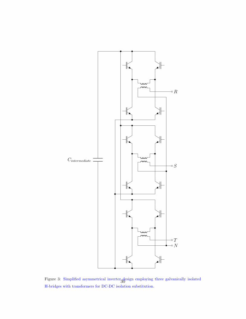
for the differential current. One of the possible solution is to use 3 different
full bridge single phase current inverters to supply each phase of low voltage260
transportation lines Patnaik et al. (2013). But in this case we need galvanic
isolations of these single phase inverters in the output, or in the DC input
size.
This isolation can be reached with using isolation transformers in the sup-
ply side. But we would like to use it a complex energetic system with specific265
inside true DC bus system feeded from Photovoltaic panel or batteries. We
have to isolate at least 2 full bridges with two way DC-DC converters. This
can complicate the physical realization but easy to simulate with two con-
trolled power source. Other possible easy to realize solution to isolate the full
bridge outputs connected to three phase lines with isolating transformers. It270
is recommended for operating and electric shock protection reasons too (Fig-
ure ??).Our distant aim to compensate other operational type line failures,
such zero current appearing. This isolation method doesn’t allow to produce
CD current components, thats why we are looking for other design. Possible
elegant solution to supplement the standard three phase inverter design with275
a fourth half bridge for Zero line, building a specific four leg inverter design
Ninad et al. (2014).
Only drawback of this solution is the complex difficult control method of
the half bridges, to keep the current sum in zero values in each moment, and
to provide the correct current paths inside the inverter. This structure has the280
lowest production cost, but in the phase of proofing the asymmetry compen-
sation we chose the DC-DC isolated full bridge design for simulation purpose
because of the simple control during simulation. As a further generalization
15

step, the injection of no harmonic current shapes will be necessary in order to
decrease the extant Total Harmonic Distortion (THD) of the network. These285
expectations yield an inverter with new structure suitable for arbitrary cur-
rent injections without limitations. The design lends similar elements like
in Gorbe et al. (2012) by means of battery charge, renewable power point
tracking, intermediate voltage, and IGBT bridge control, but in this case the
problem requires a three phase solution for the voltage unbalance reduction.290
The applied structure based on a full bridge IGBT structure used in single
phase current injection. Three different IGBT full bridge were connected at
the output point, thus our structure has three phase and neutral connection
too, to carry out any current form. The disadvantage of this structure is that
it needs 12 IGBTs in the output stage as opposed to the 6 IGBTs needed for295
a classical full bridge structure and needs three galvanically isolated direct
current (DC) voltage source for feeding. The other standard elements, that
the inverter design consists:
• Standard maximum power point tracking (MPPT) input stage, to in-
ject the maximum available power from the renewable source to the300
intermediate voltage capacitor with a simple controlled boost converter
• A half bridge current controller to charge or deploy the battery pack
connected to the complex energetic system for energy storage and en-
ergy unbalance compensation
• Intermediate voltage controller305
• Universal three phase output stage with 3 single phase full bridge IGBT
current injector and 2 high current DC-DC converter
16

This is suitable to inject any necessary current shape to the low voltage three
phase grid connection even DC currents too. Later a power loss and produc-
tion cost analysis will be necessary if the built structure will be suitable for310
asymmetric compensation of low voltage transformer area.
Of course there is a possibility that there is no renewable power available
for a longer period of time and the battery completely looses its charge. In
this case the system should work merely with the power of the connection
point but with zero energy balance. This states to operate two controller315
with semi-opposite control goals. The optimization based controller requires
current injection while the intermediate voltage controller (Figure 4) keeps
the inverters energy balance. Although for this operation some of the con-
trol’s performance should be sacrificed, unbalance compensation could be
achieved even without external renewable power, and energy storage at a320
minimum power requirement.
3.3.1. Measurements from a real unbalanced network
The measurements took place at the Faculty’s building, where a common
400 V connection point was investigated as the behaviour of the network.
The three phase 230 V line-to-ground voltages has been transformed to 6 V325
to be effectively measurable time domain with high performance NI-USB
DAQ on 10 ksample/s. Because of the limited computational capacity only a
10 second measurement was made in every hour. The measurements then has
been merged and smoothed to eliminate the inter-measurement transients.
Afterwards, the measurement data has been used as the output of a micro-330
grid segment of the Matlab/Simulink model, to test the controller and invert-
ers structure’s performance in quasi-realistic circumstances. The controllers
17

performance on the simulated microgrid’s network loss reduction can be ob-
served on (Figure 9). The measurement output is connected to a modeled
three phase load and network system, consisting of symmetrical loads and335
network segments between them. Further artificial load unbalance is not
necessary since the network’s unbalance is already present. This structure
enables to show that any point the inverter is connected could serve as qual-
ity restoration such unbalance compensation at this case. Our future plan is
to set up multiple devices on different connection points.340
3.4. Optimization based control algorithm
The problem is that, the exact mathematical relation is nonlinear because
the nonlinear, and highly time variant loads of the network, we should use
a control strategy to cope this nonlinear and time variant energy system.
For this purpose we chose an asynchronous parallel pattern search method345
(APPS) which could be able to control our scenario. We applied a vari-
ant of the gradient method that is a first-order optimization (minimization)
algorithm for a multivariate function f(x). The point x(k) corresponding
to the local minimum can be calculated from the negative gradient δf(x),
that gives the value and direction of the corresponding step in the parameter350
space. The next step is made in the direction of gradient with the proper
sign. This sequence of steps, ideally, converges to local multivariate extreme
value x(k) of the function (6).
x(k) = x(k−1) − tk∇f(x(k−1))
k ∈ N(6)
The controlled electrical system is described by multivariate non-linear
18

differential equations, the optimization of which is infeasible to derive using
the differentiation of an error function. Therefore, the optimization methods
based on direct differentiation are not applicable. In such cases, when high
computational power is needed for performing long time-consuming simula-
tions, the APPS method can utilized. The search pattern p is based on the
sampling of the error function (selected norm) on a ”grid”, and it corresponds
to variables or subsets of variables in each point in the independent variable
or parameter space easily. At the same time, the norm values at these points
can be calculated independently if ∆k > 0, using (7).
x(k+1) = x(k) + ∆kdi
if f(x(k) + ∆kdi) ≤ f(x(k))
k ∈ N
(7)
The parameter is x(k) ∈ Rn, and the search pattern p ∈ D = d1, ...dn
is taken from a predefined finite set. In this case, the error function values355
should be calculated for each pattern p in the set D. If the error function
is not decreasing in any of the directions, then the step size should be re-
duced (e.g. by half). As the competing directions are different, if there is
not enough computing power available for direction vector p, synchronization
should not be maintained. In this case we are talking about the asynchronous360
case . In the case of our controller, an individual p vector is defined for each
output variable, and the optimization was performed in each direction asyn-
chronously and shifted in time. Most likely, the error function has a single
local minimum as a symmetric amplitude and phase values. Approaching
the minimal value of norm, the controller uses adaptive increments that are365
proportional to the norm itself. Because of the complex interactions between
19
the components of the controller, only one parameter is changed at a time,
even if the values of the amplitude and phase components in specific time
slot changes. The algorithm moves along the six axes of six separate time
slots close to the local minimum of the error function.370
Unlike other similar approaches, e.g. Segui-Chilet et al. (2013), the explained
optimal controller does not rely on a measured current signal but rather mea-
suring and analysing the voltage unbalance via the proposed indicator and
optimizes the voltage shape, the latter of which depends on the nonlinear dis-
tortion of the whole low-voltage transformer area and determines additional375
power losses. The controller’s performance was compared to a non com-
pensated network, and a network consisting synchronised symmetric power
intake from a regular inverter.
In each iteration only one physical value is changing on the six dimensional
parameter field, which consists of the three amplitude and three phase val-380
ues. If the change effects with cost function reduction (the reference norm’s
normalised value), the controller holds the new value of amplitude or phase
for the controlled current sources. The advantage of this controller structure
that is not necessary to know the controlled value’s behaviour well, like we
could not determine the number and type of the other loads on the network385
Neukirchner et al. (2015a). There are however two disadvantages. First is
the low speed of control, due to the several necessary iterations (depending
on the circumstances) to find the optimal directions in the parameter space,
and the serial nature of interventions and norm calculations. The second
comes from the method itself since the controller may stuck in local minima.390
20

4. Discussion
4.1. Dynamical simulation based experiments
In order to be able to investigate the proposed optimization based un-
balance reduction control structure with the three phase inverter on a low
voltage local grid, all the elements of this complex electrical system (includ-395
ing the photovoltaic source, the inverter, the battery and the nonlinear local
grid with different types of loads) has been modeled in Matlab/Simulink en-
vironment. The primary aim of the simulation based experiments were to
serve as a proof of concept for the proposed complex control structure.
4.2. Performance analysis400
The aim of performance analysis is twofold. First of all, the proposed
voltage unbalance indicator has to be investigated in the control structure
as the cost function of the optimization based controller, and on the other
hand, the control structure itself has to be exposed against engineering ex-
pectations.405
The results of the first experiment can be seen in Figure 6 where the
geometrical norm 5 has been used as the voltage unbalance indicator and the
cost function for the optimizer. The dashed line represents the examined low
voltage local network’s unbalance norm (G) without the proposed controller
implemented in the inverter unit of the domestic powerplant while the solid410
line represents the compensated network’snorm value. The performance of
the controller with this norm is apparent, it was able to decrease the network
voltage unbalance by approximately 85 %. In this experimental setup the
21

controller has enough input energy due to the batteries and the available
solar power.415
A slightly more challangeing situation is investigated in Figure 7 where
the controller had had to operate without photovoltaic source and batteries.
This is called zero balance operation mode when the energy obtained from the
network is reinjected in such a way that the unbalance indicators decrease.
It can be seen that the performance of the controller is modest than that of420
Figure 6, but it is still acceptable.
4.2.1. Robustness analysis
The robustness of the proposed control structure is an important qual-
itative property with respect to the time dependent loads present on the
network. The robustness of the proposed controller had to be tested via425
simulation when different types of loads (inductive, capacitive, resistive) had
been varied in step changes representing represnting the on/off switching
the different types of household appliances (motors, switching mode power
supplies, electric heaters, stc.). In the experiment depicted in Figure 8, a
load change has been introduced to the network in every 15 seconds causing430
the voltage unbalance to jump to a different value (measured in the geomet-
rical norm (5)). As it can be seen in the figure the controller successfully
compensates the unbalance after each transient.
4.3. Environmental effect
The favorable effects of the proposed unbalance reduction control algo-435
rithm , i.e. increase power quality not only at the connection point but in the
whole low voltage transformer area, which causes a reduction of the effective
22

power loss and the reduction in the CO2 emission.
4.3.1. Power loss reduction on the network
Network loss reduction due to the unbalance reduction compensation con-440
trol is investigated on Figure 9 where the simulation experiment was carried
out in the circumstance when the renewable source was not shut down (e.g.
insufficient amount of sunlight) and additionally the battery was drained
completely Neukirchner et al. (2015a), Neukirchner et al. (2015b). The re-
sults show that despite of the negative cross effects of the intermediate volt-445
age controller and the unbalance reduction controller it was possible to find
the trade-off between the control goals of the different controllers (maintain
zero energy balance for the inverter and decrease the unbalance on the net-
work, respectively). The estimated loss reduction in the experimental setup
is 6.5%.450
4.3.2. CO2 footprint
The fact that this controller enables the reactive power reduction has a
favourable consequence, i.e. the power loss or equivalently CO2 emission and
the carbon footprint can also be decreased. The estimated environmental
effects of voltage asymmetry compensation can be calculated. Let us assume455
3000 kWh for the yearly electric energy consumption an average household
and 9.173% for the loss of the distribution network MVM (2013). With the
controller the losses on the simulated network are reduced by 6.5%. The
23

calculation follows (8)
Ploss = 3000 kWh · 9.173%
P comploss = 3000 kWh · (9.173 · 0.93)%
∆Ploss = Ploss − P comploss
(8)
where Ploss is the assumed network loss per household and P comploss is s the460
assumed network loss with unbalance compensation control and ∆Ploss is the
saved energy. According to (8), unbalance compensation results in an energy
savings of 19.26 kWh. Taking into account the proportion of power cur-
rently generated by fossil fuels (coal 17.3 %, gas 38.3% MVM (2013), Gorbe
et al. (2012)) and the rate of CO2 emission during electric energy production465
(1,000 g/kWh from coal and 430 g/kWh from gas), it can be concluded that
voltage unbalance compensation could reduce CO2 emissions by 6504.9 g a
year, in an average household.
5. Conclusion
The currently used measures of voltage unbalance has been extended in470
this work with a norm candidate. It is more demanding from the computa-
tional point of view but has an interesting feature namely it checks electrical
asymmetry, i.e. the norm of a ±120 degree rotated version of the ideal three-
phase phasor is zero in the geometrical sense.
The defined norm is applied as a cost function in the asymmetry reducing475
controller structure also presented in the paper. Simulations show that the
geometrical based unbalance indicator can serve as a basis of further research.
The suggested controller structure enables the residential users owning a grid
24

synchronized domestic power plant to reduce voltage unbalance measurable
at the connection point. The fundamental element of the system is a modified480
three phase inverter that is capable of the asymmetric injection of any current
waveforms to the network. The optimization based control algorithm injects
the available energy (as current waveform) in such a way, that the voltage
unbalance decreases. This optimization problem is usually constrained by
the available renewable energy supplied by the power plant.485
The control structure has been tested on a low voltage network model in a
dynamical simulation environment consisting of the models of the electrical
grid, a domestic power plant, asymmetrical inverter circuit, and different
types of loads, respectively. Different simulation experiments has been run
for each norm and for both the power constrained and unconstrained case.490
The preliminary results show that this structure can serve as a residential
level voltage quality improvement method for the three phase low voltage
network.
Acknowledgment
This research has been supported by the National Research, Development495
and Innovation Office - NKFIH, 115694. A. Magyar was supported by the
Janos Bolyai Research Scholarship of the Hungarian Academy of Sciences.
References
F. Cucchiella, I. D’Adamo, S. L. Koh, Environmental and economic analysis
of building integrated photovoltaic systems in Italian regions, Journal of500
Cleaner Production 98 (2013) 241–252.
25
J. Kaldellis, M. Simotas, D. Zafirakis, E. Kondili, Optimum autonomous
photovoltaic solution for the greek islands on the basisof energy pay-back
analysis, Journal of Cleaner Production 17 (15) (2009) 1311–1323.
M. Ortega, J. Hernandez, O. Garcıa, Measurement and assessment of power505
quality characteristics for photovoltaic systems: Harmonics, flicker, un-
balance, and slow voltage variations, Electric Power Systems Research 96
(2013) 23–35.
S. L. Huat, Y. Yonghuang, A. A. Tay, Integration issues of lithium-ion battery
into electric vehicles battery pack, Journal of Cleaner Production, article510
in press.
C.-Y. Lee, B.-K. Chen, W.-J. Lee, Y.-F. Hsu, Effects of various unbalanced
voltages on the operation performance of an induction motor under the
same voltage unbalance factor condition, Electric Power Systems Research
47 (3) (1998) 153–163.515
B. Meersman, B. Renders, L. Degroote, T. Vandoorn, L. Vandevelde, Three-
phase inverter-connected dg-units and voltage unbalance, Electric Power
Systems Research 81 (4) (2011) 899–906.
M. T. Bina, A. Kashefi, Three-phase unbalance of distribution systems: Com-
plementary analysis and experimental case study, International Journal of520
Electrical Power & Energy Systems 33 (4) (2011) 817–826.
K. Lee, T. M. Jahns, T. Lipo, V. Blasko, et al., New control method includ-
ing state observer of voltage unbalance for grid voltage-source converters,
IEEE Transactions on Industrial Electronics 57 (6) (2010) 2054–2065.
26

Y. Xu, L. M. Tolbert, J. D. Kueck, D. T. Rizy, Voltage and current unbalance525
compensation using a static var compensator, Power Electronics, IET 3 (6)
(2010) 977–988.
Y. Li, D. M. Vilathgamuwa, P. C. Loh, Microgrid power quality enhance-
ment using a three-phase four-wire grid-interfacing compensator, IEEE
Transactions on Industry Applications 41 (6) (2005) 1707–1719.530
J. Hu, M. Marinelli, M. Coppo, A. Zecchino, H. W. Bindner, Coordinated
voltage control of a decoupled three-phase on-load tap changer transformer
and photovoltaic inverters for managing unbalanced networks, Electric
Power Systems Research 131 (1) (2016) 264 – 274.
N. V. Korovkin, Q. S. Vu, R. Yazenin, F. Oleg, N. Silin, Method of unbal-535
anced power minimization in three-phase systems, Mathematics and Com-
puters in Science and Engineering Series, INASE-Saint Petersburg State
Politechnical University, Russia, 2014, pp. 134–137.
P. Gorbe, A. Magyar, K. M. Hangos, Reduction of power losses with smart
grids fueled with renewable sources and applying ev batteries, Journal of540
Cleaner Production 34 (2012) 125–137.
P. Gorbe, A. Fodor, A. Magyar, K. M. Hangos, Experimental study of the
nonlinear distortion caused by domestic power plants, Applied Thermal
Engineering 70 (2) (2014) 1288–1293.
A. D. Martin, R. S. Herrera, J. R. Vazquez, P. Crolla, G. M. Burt, Unbal-545
ance and harmonic distortion assessment in an experimental distribution
network, Electric Power Systems Research 127 (2015) 271–279.
27
P. G. Kini, R. C. Bansal, R. S. Aithal, A novel approach toward interpre-
tation and application of voltage unbalance factor, IEEE Transactions on
Industrial Electronics 54 (4) (2007) 2315–2322.550
H. Wen, D. Cheng, Z. Teng, S. Guo, F. Li, Approximate algorithm for fast
calculating voltage unbalance factor of three-phase power system, IEEE
Transactions on Industrial Informatics 10 (3) (2014) 1799–1805.
L. R. Araujo, D. R. R. Penido, S. Carneiro, J. L. R. Pereira, A three-phase
optimal power-flow algorithm to mitigate voltage unbalance, IEEE Trans-555
actions on Power Delivery 28 (4) (2013) 2394–2402.
L. Neukirchner, P. Gorbe, A. Gollei, A. Magyar, Carbon footprint reduc-
tion via voltage asymmetry compensation of three-phase low voltage grid
utilizing small domestic power plants, Chemical Engineering Transactions
35 (1) (2015) 283–288.560
L. Neukirchner, P. Gorbe, A. Magyar, Examination of different voltage asym-
metry norms under transient behavior of three-phase low voltage power
systems containing small domestic power plants, in: PowerTech, 2015
IEEE Eindhoven, IEEE, 2015, pp. 1–6.
S. Segui-Chilet, F. Gimeno-Sales, S. Orts, G. Garcera, E. Figueres,565
M. Alcaniz, R. Masot, Approach to unbalance power active compensa-
tion under linear load unbalances and fundamental voltage asymmetries,
International Journal of Electrical Power & Energy Systems 29 (7) (2007)
526–539.
MVM, Statistical data of the Hungarian electricity system. (2013)570
28

S.S. Patnaik and A.K. Panda, Three-level H-bridge and three H-bridges-
based three-phase four-wire shunt active power filter topologies for high
voltage applications, International Journal of Electrical Power & Energy
Systems 51 (1) (2013) 298 - 306.575
N.A. Ninad, L. Lopes, Per-phase vector control strategy for a four-leg voltage
source inverter operating with highly unbalanced loads in stand-alone hy-
brid systems, International Journal of Electrical Power & Energy Systems
55 (1) (2014) 449 - 459.580
29
Cintermediate
NT
S
R
Figure 3: Simplified asymmetrical inverter design employing three galvanically isolated
H-bridges with transformers for DC-DC isolation substitution.30

Figure 4: The asymmetrical inverter design, which implies 3 single phase full bridge IGBT
current injector to form the injected asymmetrical current shapes for voltage unbalance
compensation.
31

Figure 5: The optimization algorithm implemented for current control. In a repeating
sequence on every dimension on the six dimensional parameter field a one dimensional
linear optimization is carried out. If the optimization results cost reduction, altered current
feedback get registered in means of amplitude and phase values.
Figure 6: Unbalance reduction control system performance with half charged battery and
photovoltaic power source available. The underlying unbalance norm is the geometrical
one (G) in this experiment. After starting the controller at t = 0.1s the unbalance measure
G of the network significantly decrease.
32

Figure 7: Unbalance reduction control system performance without battery and renewable
source (zero energy balance operation). The performance reduction is clearly observable
compared to the case when external power source is available (Figure 6), but as result the
voltage unbalance indicator G reduced by the average value of 14.78%.
Figure 8: Robustness analysis with respect to step type changes in the network load
(and voltage unbalance, respectively). The unbalance reduction controller successfully
compensates the changes in the network voltage unbalance norm (G) value.
33

Figure 9: Compensation control’s loss reduction during zero energy balance operation on
the modeled network, where Ploss indicates the effective power losses and P comploss effective
power losses during control of the network. As result the network losses reduced by mean
6.5%.
Figure 10: Intermediate puffer capacitance’s voltage within boundaries (600±10 V), during
zero energy balance operation mode of the voltage unbalance compensation controller. Uim
indicates intermediate the capacitance’s voltage.
34