
Voltage Control System: Proportional Integral (PI) Controllers Team Purple: John Pangle Jessica...
62
Voltage Control System: Proportional Integral (PI) Controllers Team Purple: John Pangle Jessica Raymond Justin Whitt ENGR 329 November 30, 2005
-
date post
19-Dec-2015 -
Category
Documents
-
view
217 -
download
1
Transcript of Voltage Control System: Proportional Integral (PI) Controllers Team Purple: John Pangle Jessica...

Voltage Control System: Proportional Integral
(PI) Controllers
Team Purple:John Pangle
Jessica Raymond
Justin WhittENGR 329
November 30, 2005

Outline
Voltage System Background Previous Work: SSOC, Step, Sine,
Bode, P-Only PI Model Results PI Experimental Results Conclusions Luyben Method Review Recent Results Conclusions

Purple Team 9/14/05
Voltage System Schematic

Block Diagram
M(t) is measured in % and C(t) is in Volts.

Purple Team 10/25/05
Voltage System SSOC
0
20
40
60
80
100
120
140
0 10 20 30 40 50 60 70 80 90 100
m(t), Input (%)
c(t
), O
utp
ut
(V) Operating Range:
Output = 50V to 140V
Operating Range:Input = 70% to 100%
75%-100% InputSlope = 2 V/%

Background: Step Input
50
120
40 50 60
Time (sec)
Ou
tpu
t (v
olt
s)
70
90
40 50 60
Time (sec)
Inp
ut
(%)
Voltage System
K – Gain (Volt/%)t0 – Dead Time (s)τ – Time Constant (s)

Background: FOPDT Fit
Voltage System 70% Base, 20% Step
Trial 1
70
75
80
85
90
45 47 49 51 53 55
Time (sec)
40
60
80
100
120
Output, c(t) (V)
Input, m(t) (%)
Fit 3 Data:K= 3 V / %τ= 0.9 secto = 0 sec

FOPDT Model
50
55
60
65
70
75
80
85
90
95
10 15 20 25 30
Time (sec)
Input (%)
50
60
70
80
90
100
110
120
Experimental Input
Model Input
Experimental Output
Model Output
Output (V)
Voltage SystemExperimental vs. Model
90%-70% Step(Trial 1)
Team Purple09/20/05
K = 2 V / %
to = 0 s
τ = 0.5 s

Background: Sinusoidal Input
80
90
100
11 11.5 12
Time (sec)
Ou
tpu
t (V
olt
s)
74
80
86
11 11.5 12
Time (sec)
Inp
ut
(%)
K – Gain (Volt/%)t0 – Dead Time (s)τ – Time Constant (s)

Values taken from Point A AR = 1.5 f = 4 Hz
Bode Plot K = 2 V / %
= 0.04 sec
to = 0.08 sec
)(tan 1
ot
Voltage System Experimental Bode Plot80% Base 5 Amplitude
0.1
1
10
0.1 1 10 100
Asp
ect
Rat
io (
V/%
)
fu = 5 Hz
order = 2 Hz
K = 2 V / %
1/Kcu = 1 % / V
Kcu = 1 V / %
-450
-360
-270
-180
-90
0
0.1 1 10 100
Frequency (Hz)
Ph
ase
An
gle
JDP
tau = 0.04 secto = 0.08 sec

Model Bode Plot, 80% Base 5 Amplitude
0.1
1
10
0.1 1 10 100
Frequency (Hz)
Asp
ect
Rati
o (
V/%
) K = 2 V/%
order = 2 Hz
fu = 5 Hz
1/Kcu = 1 %/V
Kcu = 1 V/%
-450
-400
-350
-300
-250
-200
-150
-100
-50
0
0.1 1 10 100
Ph
ase A
ng
le
Experimental Model
Model ValuesK = 2.0 V/%tau = 0.04 secto = 0.08 sec
JDP
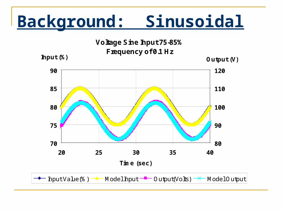
Background: Sinusoidal InputVoltage Sine Input 75-85%
Frequency of 0.1 Hz
70
75
80
85
90
20 25 30 35 40
Time (sec)
Input (%)
80
90
100
110
120
Output (V)
Input Value(%) Model Input Output(Volts) Model Output

Background: FOPDT Averages
K (v / %) 2
τ (sec) 0.04
to (sec) 0.06
FOPDT ParametersAverages of

Background: Feedback Loops
Kc
1
0
s
Ke st
R(volts)
E(volts)
M(%)
C(volts)
+ -
ste 0
ste 0
st
st
e st
21
21
0
0
0
CE =

Background: P-Only ControllersVoltage System P-Only Root Locus
-60
-40
-20
0
20
40
60
-40 -35 -30 -25 -20 -15 -10 -5 0 5
REAL AXIS
IMA
GIN
AR
Y A
XIS
KQD = .8 KCU = 1
KCD = .01
K1/500 = .2 K1/10 = .6
fu = 8 Hz
Units of KC = %/ V

Background: P-Only ControllersVoltage System
Proportional Only Model
105
110
115
120
125
5 5.5 6
TIME (sec)
OU
TP
UT
/SE
T P
OIN
T (
V)
JWTeam Purple10/28/05
Kccd = 0.01 % / V
Offset = - 9 v

Voltage System Proportional Only
Experimental
70
75
80
85
90
95
100
9 9.5 10 10.5 11 11.5 12
Time (sec)
Inp
ut
(%)
100
105
110
115
120
125
130
Ou
tpu
t (V
)
Input Value(%) Output(Volts) SET-P(Volts)
Kccd = .01 % / V
Decay Ratio: 0MonotonicSettling Time: 0.1 secOffset: - 23 V
Background: P-Only ControllersVoltage System SSOC & Controller Operating Line
90
100
110
120
130
91.8 91.84 91.88 91.92 91.96 92 92.04 92.08
Input (%)
Ou
tpu
t (
V )
Kccd = 0.01 % / V
Delta R = - 20 VOffset = - 23 V

Background: P-Only ControllersVoltage System
Proportional Only Model
105
110
115
120
125
5 5.5 6
TIME (sec)
OU
TP
UT
/SE
T P
OIN
T (
V)
JWTeam Purple10/28/05
Kc1/500 = 0.2 % / VOffset = - 7 v

Voltage System Proportional Only Experimental
70
75
80
85
90
95
100
9 9.5 10 10.5 11 11.5 12
Time (sec)
Inp
ut
(%)
100
105
110
115
120
125
130
Ou
tpu
t (V
)
Input Value(%) Output(Volts) SET-P(Volts)
Kc1/500 = 0.2 % / V
Decay Ratio: 0OscillatorySettling Time: 0.5 secOffset: - 16 V
Background: P-Only ControllersVoltage System SSOC & Controller Operating Line
100
105
110
115
120
125
87 88 89 90 91 92 93
Input (%)
Ou
tpu
t (
V )
Kc1/500 = 0.2 % / V
Delta R = - 20 VOffset = - 14 V

Background: P-Only ControllersVoltage System
Proportional Only Model
105
110
115
120
125
5 5.5 6
TIME (sec)
OU
TP
UT
/SE
T P
OIN
T (
V)
JWTeam Purple10/28/05
Kc1/10 = 0.6 % / V
Offset = - 4 v

Background: P-Only Controllers
RESULTS FOR PROPORTIONAL FEEDBACK CONTROLLERSET-P(Volts)
Voltage System Proportional Only Experimental
70
75
80
85
90
95
100
9 9.5 10 10.5 11 11.5 12
Time (sec)
Inp
ut
(%)
100
105
110
115
120
125
130
Ou
tpu
t (V
)
Input Value(%) Output(Volts) SET-P(Volts)
Kc1/10 = 0.6 % / V
Decay Ratio: 0.7OscillatorySettling Time: 0.6 secOffset: - 12 V
Voltage System SSOC & Controller Operating Line
100
105
110
115
120
125
80 82 84 86 88 90 92 94
Input (%)
Ou
tpu
t (
V )
Kc1/10 = 0.6 % / V
Delta R = - 20 VOffset = - 8 V

Background: P-Only ControllersVoltage System
Proportional Only Model
105
110
115
120
125
5 5.5 6
TIME (sec)
OU
TP
UT
/SE
T P
OIN
T (
V)
JWTeam Purple10/28/05
KQD = 0.8 % / V
Offset = - 3 v

Background: P-Only ControllersVoltage System Proportional Only Experimental
70
75
80
85
90
95
100
9 9.5 10 10.5 11 11.5 12
Time (sec)
Inp
ut
(%)
100
105
110
115
120
125
130
Ou
tpu
t (V
)
Input Value(%) Output(Volts) SET-P(Volts)
KcQD = 0.8 % / V
Decay Ratio: 1OscillatorySettling Time: neverOffset: - 8 V
Voltage System SSOC & Controller Operating Line
100
105
110
115
120
125
80 82 84 86 88 90 92 94
Input (%)
Ou
tpu
t (
V )
KcQD = 0.8 % / V
Delta R = - 20 VOffset = - 7 V

Background: P-Only ControllersVoltage System
Proportional Only Model
100
110
120
130
140
5 5.5 6
TIME (sec)
OU
TP
UT
/SE
T P
OIN
T (
V)
JWTeam Purple10/28/05
Kcu = 1 % / V

Background: P-Only ControllersVoltage System Proportional Only Experimental
70
75
80
85
90
95
100
9 9.5 10 10.5 11 11.5 12
Time (sec)
Inp
ut (
%)
100
105
110
115
120
125
130
Input Value(%) Output(Volts) SET-P(Volts)
Kc = 1 % / V
Decay Ratio: 1OscillatorySettling Time: neverOffset: - 5 V
Voltage System SSOC & Controller Operating Line
100
105
110
115
120
125
84 86 88 90 92 94
Input (%)
Ou
tpu
t (
V )
Kc = 1 % / VDelta R = - 20 VOffset = - 5 V

Background: P-Only Controllers
Agree
Moderately AgreeDisagree
Symbol
RL Value for Kc (%/V) Model Experimental
KCD 0.01 0 0K1/500 0.2 0 0K1/10 0.6 0.1 0.7KQD 0.8 0.2 1Kcu 1 1 1
Decay Ratio

Background: P-Only Controllers
Agree
Moderately AgreeDisagree
SymbolRL Value for
Kc (%/V) Model ( sec ) Experimental ( sec )KCD 0.01 0.1 0.1
K1/500 0.2 0.2 0.5K1/10 0.6 0.4 1.2KQD 0.8 0.5 neverKcu 1 never never
Settling Time

Background: P-Only Controllers
Agree
Moderately AgreeDisagree
SymbolRL Value for
Kc (%/V) Model ( V ) Experimental ( V )Controller
Line (V) FVT ( V )KCD 0.01 -20 -23 -23 -20
K1/500 0.2 -14 -16 -14 -14K1/10 0.6 -9 -8 -8 -9KQD 0.8 -8 -8 -7 -8Kcu 1 CBD -5 -5 -6
Offset

PI Controllers
M(s)
1
0
s
Ke st
R(s) E(s) C(s)
+ -
sK
Ic
11

PI ControllersVoltage System PI Controller I= .2 s
-60
-40
-20
0
20
40
60
-40 -30 -20 -10 0REAL
IMA
GIN
AR
YKcCD= 0.01 % / V
KcQD= 0.7 % / VKcu= 1 % / V
fu= 8 Hz
Kc1/500= 0.2 % / V
Kc1/10= 0.6 % / V
FOPDT:K= 2 V / %Tau=0.04 sto=0.06 s

PI ControllersVoltage System PI Controller i = 0.1
-60
-40
-20
0
20
40
60
-40 -30 -20 -10 0
IMA
GIN
AR
Y
KcCD = 0.01
Kc-500 = 0.2
Kc-10 = 0.6
Kcu = 1
KcQD = 0.7
fu = 7 Hz
FOPDT:K= 2 V / %Tau=0.04 sto=0.06 s

PI ControllersVoltage System PI Controller I= .01 s
-40
-20
0
20
40
-10 -8 -6 -4 -2 0REAL
IMA
GIN
AR
Y
KcCD= 0.02 % / V
KcQD= 0.07 % / V
Kcu= 0.1 % / V fu= 3.2 Hz
Kc1/500= 0.03 % / V
Kc1/10= 0.05 % / V
FOPDT:K= 2 V / %Tau=0.04 sto=0.06 s
Voltage System PI Controller I= .01 s
-60
-40
-20
0
20
40
60
-40 -30 -20 -10 0REAL
IMA
GIN
AR
Y
FOPDT:K= 2 V / %Tau=0.04 sto=0.06 s

PI Controllers (Kc = 0.8)Voltage System
PI ControllerExperimental
0
25
50
75
100
25 25.5 26 26.5 27
Time (sec)
Input (%)
100
110
120
130
140Output (volt)
Kc = 0.8 % / v
τi = 0.2
DR = 1UltimateSettling Time = Never
JWTeam Purple11/27/05
Voltage SystemPI ControllerExperimental
0
25
50
75
100
25 25.5 26 26.5 27
Time (sec)
Input (%)
100
110
120
130
140Output (volt)
JWTeam Purple11/27/05
Kc = 0.8 % / vτi = 0.1
DR = 1UltimateSettling Time = Never
Voltage SystemPI ControllerExperimental
0
25
50
75
100
25 25.5 26 26.5 27
Time (sec)
Input (%)
100
110
120
130
140Output (volt)
JWTeam Purple11/27/05
Kc = 0.8 % / vτi = 0.05
DR = 1UltimateSettling Time = Never
Voltage SystemPI ControllerExperimental
0
25
50
75
100
25 25.5 26 26.5 27
Time (sec)
Input (%)
100
110
120
130
140Output (volt)
JWTeam Purple11/27/05
Kc = 0.8 % / vτi = 0.03
DR = 1UnstableSettling Time = Never
Voltage SystemPI ControllerExperimental
0
25
50
75
100
25 25.5 26 26.5 27
Time (sec)
Input (%)
100
110
120
130
140
Output (volt)
JWTeam Purple11/27/05
Kc = 0.8 % / vτi = 0.01
DR = 1UnstableSettling Time = Never

PI Controllers (Kc = 0.5)Voltage System
PI ControllerExperimental
0
25
50
75
100
25 25.5 26 26.5 27
Time (sec)
Input (%)
100
110
120
130
140Output (volt)
JWTeam Purple11/27/05
Kc = 0.5 % / vτi = 0.2 s
DR = 0.63Under DampedSettling Time = 1 s
Voltage SystemPI ControllerExperimental
0
25
50
75
100
25 25.5 26 26.5 27
Time (sec)
Input (%)
100
110
120
130
140
Output (volt)
JWTeam Purple11/27/05
Kc = 0.5 % / vτi = 0.1 s
DR = 0.54Under DampedSettling Time = 0.9 s
Voltage SystemPI ControllerExperimental
0
25
50
75
100
25 25.5 26 26.5 27
Time (sec)
Input (%)
80
90
100
110
120
130
140
Output (volt)
JWTeam Purple11/27/05
Kc = 0.5 % / vτi = 0.05 s
DR = 0.96Under DampedSettling Time = 2 s
`
Voltage SystemPI ControllerExperimental
0
25
50
75
100
25 25.5 26 26.5 27
Time (sec)
Input (%)
100
110
120
130
140
Output (volt)
JWTeam Purple11/27/05
Kc = 0.5 % / vτi = 0.025 s
DR = 1UltimateSettling Time = Never
Voltage SystemPI ControllerExperimental
0
25
50
75
100
25 25.5 26 26.5 27
Time (sec)
Input (%)
100
110
120
130
140
Output (volt)
JWTeam Purple11/27/05
Kc = 0.5 % / vτi = 0.01 s
DR = 1UnstableSettling Time = Never

PI Controllers (Kc = 0.4)Voltage System
PI ControllerExperimental
0
25
50
75
100
25 25.5 26 26.5 27
Time (sec)
Input (%)
100
110
120
130
140Output (volt)
JWTeam Purple11/27/05
Kc = 0.4 % / vτi = 0.2 s
DR = 0.49Under DampedSettling Time = 0.7 s
Voltage SystemPI ControllerExperimental
0
25
50
75
100
25 25.2 25.4 25.6 25.8 26
Time (sec)
Input (%)
100
110
120
130
140
Output (volt)
JWTeam Purple11/27/05
Kc = 0.4 % / vτi = 0.1 s
DR = 0.41Under DampedSettling Time = 0.6 s
Voltage SystemPI ControllerExperimental
0
25
50
75
100
25 25.5 26 26.5 27
Time (sec)
Input (%)
100
110
120
130
140
Output (volt)
JWTeam Purple11/27/05
Kc = 0.4 % / vτi = 0.05 s
DR = 0.56Under DampedSettling Time = 0.7 s
Voltage SystemPI ControllerExperimental
0
25
50
75
100
25 25.5 26 26.5 27
Time (sec)
Input (%)
100
110
120
130
140Output (volt)
JWTeam Purple11/27/05
Kc = 0.4 % / vτi = 0.03 s
DR = 0.86Under DampedSettling Time = 13 s
Voltage SystemPI ControllerExperimental
0
25
50
75
100
25 25.5 26 26.5 27
Time (sec)
Input (%)
100
110
120
130
140
Output (volt)
JWTeam Purple11/27/05
Kc = 0.4 % / vτi = 0.01 s
DR = 1UnstableSettling Time = Never

PI Controllers (Kc = 0.2)Voltage System
PI ControllerExperimental
0
25
50
75
100
25 25.5 26 26.5 27
Time (sec)
Input (%)
100
110
120
130
140Output (volt)
JWTeam Purple11/27/05
Kc = 0.2 % / vτi = 0.2 s
DR = 0.29Quarter DecaySettling Time = 0.9 s
Voltage SystemPI ControllerExperimental
0
25
50
75
100
25 25.5 26 26.5 27
Time (sec)
Input (%)
100
110
120
130
140
Output (volt)
JWTeam Purple11/27/05
Kc = 0.2 % / vτi = 0.1 s
DR = 0.25Quarter DecaySettling Time = 0.5 s
Voltage SystemPI ControllerExperimental
0
25
50
75
100
25 25.5 26 26.5 27
Time (sec)
Input (%)
100
110
120
130
140
Output (volt)
JWTeam Purple11/27/05
Kc = 0.2 % / vτi = 0.05 s
DR = 0Critically DampedSettling Time = 0.4 s
Voltage SystemPI ControllerExperimental
0
25
50
75
100
25 25.5 26 26.5 27
Time (sec)
Input (%)
100
110
120
130
140
Output (volt)
JWTeam Purple11/27/05
Kc = 0.2 % / vτi = 0.03 s
DR = 0Critically DampedSettling Time = 0.6 s
Voltage SystemPI ControllerExperimental
0
25
50
75
100
25 25.5 26 26.5 27
Time (sec)
Input (%)
100
110
120
130
140
Output (volt)
JWTeam Purple11/27/05
Kc = 0.2 % / vτi = 0.01 s
DR = 1UltimateSettling Time = Never

PI Controllers (Kc = 0.1)Voltage System
PI ControllerExperimental
0
25
50
75
100
25 25.5 26 26.5 27
Time (sec)
Input (%)
100
110
120
130
140
Output (volt)
JWTeam Purple11/27/05
Kc = 0.1 % / v
τi = 0.2 sDR = 0Critcally DampedSettling Time = 2 s
Voltage SystemPI ControllerExperimental
0
25
50
75
100
25 25.5 26 26.5 27
Time (sec)
Input (%)
100
110
120
130
140
Output (volt)
JWTeam Purple11/27/05
Kc = 0.1 % / vτi = 0.1 s
DR = 0Critically DampedSettling Time = 1 s
Voltage SystemPI ControllerExperimental
0
25
50
75
100
25 25.5 26 26.5 27
Time (sec)
Input (%)
100
110
120
130
140
Output (volt)
JWTeam Purple11/27/05
Kc = 0.1 % / vτi = 0.05 s
DR = 0Over DampedSettling Time = 0.6 s
Voltage SystemPI ControllerExperimental
0
25
50
75
100
25 25.5 26 26.5 27
Time (sec)
Input (%)
100
110
120
130
140
Output (volt)
JWTeam Purple11/27/05
Kc = 0.1 % / vτi = 0.03 s
DR = 0Over DampedSettling Time = 0.4 s
Voltage SystemPI ControllerExperimental
0
25
50
75
100
25 25.5 26 26.5 27
Time (sec)
Input (%)
100
110
120
130
140
Output (volt)
JWTeam Purple11/27/05
Kc = 0.1 % / vτi = 0.01 s
DR = 0.26Quarter DecaySettling Time = 0.6 s

PI Controllers (Kc = 0.05)Voltage System
PI ControllerExperimental
0
25
50
75
100
25 25.5 26 26.5 27
Time (sec)
Input (%)
100
110
120
130
140Output (volt)
JWTeam Purple11/27/05
Kc = 0.05 % / vτi = 0.2 s
DR = 0Over DampedSettling Time = 5 s
Voltage SystemPI ControllerExperimental
0
25
50
75
100
25 25.5 26 26.5 27
Time (sec)
Input (%)
100
110
120
130
140
Output (volt)
JWTeam Purple11/27/05
Kc = 0.05 % / vτi = 0.1 s
DR = 0Over DampedSettling Time = 2 s
Voltage SystemPI ControllerExperimental
0
25
50
75
100
25 25.5 26 26.5 27
Time (sec)
Input (%)
100
110
120
130
140
Output (volt)
JWTeam Purple11/27/05
Kc = 0.05 % / vτi = 0.05 s
DR = 0Over DampedSettling Time = 0.9 s
Voltage SystemPI ControllerExperimental
0
25
50
75
100
25 25.5 26 26.5 27
Time (sec)
Input (%)
100
110
120
130
140
Output (volt)
JWTeam Purple11/27/05
Kc = 0.05 % / vτi = 0.03 sDR = 0Over DampedSettling Time = 0.6 s
Voltage SystemPI ControllerExperimental
0
25
50
75
100
25 25.5 26 26.5 27
Time (sec)
Input (%)
100
110
120
130
140
Output (volt)
JWTeam Purple11/27/05
Kc = 0.05 % / vτi = 0.01 s
DR = 0Critically DampedSettling Time = 0.3 s

PI ControllersVoltage System
PI ControllerExperimental
8
0
1
2
3
4
5
6
7
8
0.8 0.5 0.4 0.2 0.1 0.05
Kc ( % / volt)
Se
ttli
ng
Tim
e (
se
c)
0.2
0.1
0.05
0.03
0.0188 8
τI

PI ControllersVoltage System
PI ControllerExperimental
0.0
0.2
0.4
0.6
0.8
1.0
1.2
0.8 0.5 0.4 0.2 0.1 0.05
Kc ( % / volt)
Dec
ay R
atio
0.2
0.1
0.05
0.03
0.01
τI

PI ControllersVoltage System
PI ControllerExperimental
0.00.1
0.20.3
0.40.5
0.60.7
0.80.9
1.0
0.0 0.2 0.4 0.6 0.8 1.0
Kc (% / Volt)
Dec
ay R
atio
0.2
0.1
0.05
0.03
0.01
τI

PI ControllersVoltage System
PI ControllerExperimental
0
25
50
75
100
0 5 10 15 20 25 30 35 40 45
Time (sec)
Input (% )
0
20
40
60
80
100
120
140
m(t) % c(t) volts Set Point (volts)
Output (volt)
Kc = 0.2 % / v
τi = 0.03
JWTeam Purple11/27/05

Conclusions
Kc (% / volt)
Decay Ratio
Monotonic/ Oscillatory
Settling Time (sec)
Description
0.8 1.0 Oscillatory Never Ultimate0.5 1.0 Oscillatory 0.9 Under Damped0.4 0.3 Oscillatory 0.4 Quarter Decay0.2 0.1 Oscillatory 0.9 Tenth Decay0.1 0.0 Monotonic 1 Critically Damped
0.05 0.0 Monotonic 3 Over Damped
Recommend PI over P-only Recommend τI = 0.1 Yields widest range of desirable decay ratios. Provides acceptable settling times.

Luyben Method
Presented by
William L. Luyben, Ph.D
at Reno AIChE Meeting
Nov. 6, 2001

Luyben Method
1. Insert relay into feedback loop.
Relay
1
0
s
Ke st
R(volts)
E(volts)
M(%)
C(volts)
+ -

Luyben Method
2. Specify upper & lower limits of m(t)

Luyben Method Proportional Feedback Voltage Station Enter this Information about you:
Name Justin Whitt
Location emcs
E-mail address j_w hitt@com
Enter these Parameters for the Experiment:
Length of experiment (sec): 30
Lab Wizard
Controller output bias value (%): (=Baseline input value (%))
80
Lab Wizard
Controller tuning parameter and Set Point
Proportional controller gain, Kc (%/Volt): 9999999999
Lab Wizard
Set-point value (Volts): 100
Lab Wizard
Controller Output Clamping Specifications
Floor (%): 75
Lab Wizard
Ceiling (%): 85
Lab Wizard
RUN EXPERIMENT

Luyben MethodVoltage System
Relay Feedback TestInput:95%, A=5
85
90
95
100
105
110
22.5 22.6 22.7 22.8 22.9 23.0 23.1
Time (sec)
Input (%)
80859095100105110115120125130
JWTeam Purple10/06/05
Input m(t) (%)
Output c(t) (Volts)
Setpoint r(t) (Volts)

Luyben Method
3.Find Tu from c(t)
4.Calculate Kcu
a
hK cu
4

Luyben MethodVoltage System
Relay Feedback TestInput:80%, A=5
70
75
80
85
90
22.5 22.6 22.7 22.8 22.9 23.0 23.1
Time (sec)
Inp
ut
(%)
JWTeam Purple10/06/05
Input m(t) (%)
h
h = 5%
a
Kcu%)5(4

Luyben MethodVoltage System
Relay Feedback TestInput:80%, A=5
90
95
100
105
22.5 22.6 22.7 22.8 22.9 23.0 23.1
Time (sec)
Ou
tpu
t (V
olt
s)
JWTeam Purple10/06/05
Output c(t) (Volts)
a
a = 5.1 Volts Tu
Tu = 0.19s
voltvoltsK cu
%3.1
)_1.5(
%)5(4
HzsT
fu
u 3.519.0
11

Luyben MethodVoltage System
Relay Feedback TestInput:80%, A=5
90
95
100
105
22.5 22.6 22.7 22.8 22.9 23.0 23.1
Time (sec)
Ou
tpu
t (V
olt
s)
JWTeam Purple10/06/05
Output c(t) (Volts)
a
a = 5.1 Volts Tu
Tu = 0.19s
voltvoltsK cu
%3.1
)_1.5(
%)5(4
HzsT
fu
u 3.519.0
11

Luyben Method
Voltage System Ultimate Frequency
0
2
4
6
8
75%-85% 90%-100%
fu (Hz)
Bode Luyben P-Only RL
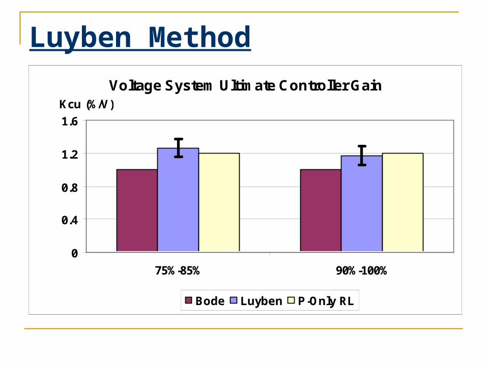
Luyben Method
Voltage System Ultimate Controller Gain
0
0.4
0.8
1.2
1.6
75%-85% 90%-100%
Kcu (%/V)
Bode Luyben P-Only RL

Luyben Method
What about to and τ? I still have to run another test right?

Luyben Method
uP
bF
4Curvature Factor =
Y
0
a
a/2
b
Pu
time
t1 t2

Luyben Method
Y0
aa/2
b
Pu
time1)(
s
eKG
stp
s
o
)/(
)(
o
stps
t
eKG o
)0/(
)/1()(
o
st
s
ts
eG
o
time
Y
0
a
-a
aPu
22
1
F
Pb u
Y 0
Pu
time
a
5.08
1
F
Pb u
t1 t2
F=2
F=0.5

Luyben Method
)(6788.2)(8974.9
)(7147.122783.5)/(log32
10
FF
Fto
F=1 for Voltage System
to/τ = 2

Luyben Method
to = 2τ
)(tan 1
ot
)(tan2
)(tan1
10
uu
uut
τ = 0.01 and to= 0.02

Luyben Method
Voltage System Time Constant
0
0.01
0.02
0.03
0.04
0.05
75%-85% 90%-100%
Tau (sec)
Bode Luyben

Luyben Method
Voltage System Dead Time
0
0.02
0.04
0.06
0.08
0.1
75%-85% 90%-100%
To (sec)
Bode Luyben

Conclusion
Only one simple test required (7 steps)
Works well for any order systems
Similar Results to Bode


![Whitt - [3]](https://static.fdocuments.net/doc/165x107/577cd3561a28ab9e789708cd/whitt-3.jpg)


