Vokera Unicabhe Install Boiler Manual - Heating …...5.8 Final flushing of the heating system 18...
40
Supplied By www.heating spares.co Tel. 0161 620 6677 Installation & Servicing Instructions THESE INSTRUCTIONS TO BE RETAINED BY USER Vokèra is a licensed member of the Benchmark scheme which aims to improve the standards of installation and commissioning of domestic hot water systems in the UK. Unica BHE High efficiency combi boiler G.C. NUMBER UNICA 32 BHE N° 47-094-99 0694 0694BR1207
Transcript of Vokera Unicabhe Install Boiler Manual - Heating …...5.8 Final flushing of the heating system 18...

Supplied By www.heating spares.co Tel. 0161 620 6677
Installation
& Servicing
Instructions
THESE INSTRUCTIONSTO BE RETAINEDBY USER
Vokèra is a licensed member of the Benchmark schemewhich aims to improve the standards of installation and commissioning of domestic hot water systems in the UK.
Unica BHEHigh efficiency combi boiler
G.C. NUMBER
UNICA 32 BHE N° 47-094-99
06940694BR1207

Supplied By www.heating spares.co Tel. 0161 620 6677
ContentsDesign principles & operating sequence Page1.1 Principle components 31.2 Mode of operation (at rest) 31.3 Mode of operation (heating) 31.4 Mode of operation (Hot water) 31.5 Safety devices 3
Technical data Page2.1 Central heating 42.2 Domestic hot water 42.3 Gas pressures 42.4 Expansion vessel 42.5 Dimensions 42.6 Clearances 42.7 Connections 42.8 Electrical 42.9 Flue details (concentric) 42.9A Flue details (twin pipes) 42.10 Efficiency 42.11 Emissions 42.12 Pump duty 5
General requirements (UK) Page3.1 Related documents 63.2 Location of appliance 63.3 Gas supply 63.4 Flue system 63.5 Air supply 63.6 Water circulation 63.7 Electrical supply 73.8 Mounting on a combustible surface 73.9 Timber framed buildings 73.10 Inhibitors 73.11 Showers 7
General requirements (EIRE) Page3A.1 Related documents 83A.2 Location of appliance 83A.3 Gas supply 83A.4 Flue system 83A.5 Air supply 83A.6 Water circulation 83A.7 Electrical supply 93A.8 Mounting on a combustible surface 93A.9 Timber framed buildings 93A.10 Inhibitors 93A.11 Showers 93A.12 Declaration of conformity 9
Installation Page4.1 Delivery 104.2 Contents 104.3 Unpacking 104.4 Preparation for mounting the appliance 104.5 Fitting the flue 114.6 Connecting the gas & water 154.7 Electrical connections 16
Commissioning Page5.1 Gas supply installation 175.2 The heating system 175.3 Initial filling of the system 175.4 Initial flushing of the system 175.5 Pre-operation checks 175.6 Initial lighting 175.7 Checking gas pressure & combustion analysis 175.8 Final flushing of the heating system 185.9 Setting the boiler operating temperature 185.10 Setting the system design pressure 185.11 Regulating the central heating system 185.12 Final checks 185.13 Instructing the user 18
Servicing Page6.1 General 196.2 Routine annual servicing 196.3 Replacement of components 196.4 Component removal procedure 196.5 Pump assembly 196.6 Safety valve 206.7 Lower automatic air release valves 206.8 Water pressure switch 206.9 Primary thermistor 206.10 Return thermistor 206.11 Printed circuit board 206.12 Gas valve 206.13 Electrodes and condense sensor 216.14 Flue fan & mixer 216.15 Burner 216.16 Main heat exchanger 226.17 Automatic by-pass 226.18 Expansion vessel 226.19 Condense trap removal 226.20 Flue collector removal 23
Checks, adjustments and fault finding Page7.1 Checking appliance operation 247.2 Appliance modes of operation 247.3 Appliance fan speed 257.4 Checking the CO2 & adjusting the valve 257.5 Combustion analysis test 267.6 Checking the expansion vessel 267.7 External faults 267.8 Electrical checks 267.9 Fault finding 277.10 Boiler configuration 277.11 Final fault codes 27
Wiring diagrams Page8.1 External wiring 288.2 Typical control applications 288.3 Other devices 28
Exploded diagrams Page9.1 Table 1 309.2 Table 2 319.3 Table 3 319.4 Table 4 329.5 Table 5 33
L.P.G. instructions Page10.1 Related documents 3410.2 Technical data 3410.3 Converting the appliance gas type 3410.4 Gas supply 3410.5 Gas supply installation 3410.6 Adjusting the gas valve 3410.7 Appliance fan speed 35
Benchmark 36-37

Supplied By www.heating spares.co Tel. 0161 620 66771UNICA BHE
INTRODUCTION
General layout (fig. 1)1 Electrical connection box2 Safety valve3 Three port valve actuator4 Domestic hot water heat exchanger5 Pump6 Bottom auto air vent (AAV)7 Condense trap8 Return sensor9 Expansion vessel10 Fumes thermostat11 Flue gas analysis test point12 Flue outlet & air intake13 Ignition transformer14 Top AAV15 Flow sensor16 High limit thermostat17 Sensing Electrode18 Spark Electrode
fig. 1
The Unica BHE is a high-efficiency combination boiler withan output to DHW of 32kW. This appliance – by design –incorporates electronic ignition, circulating pump, expansionvessel, safety valve, pressure gauge and automatic by-pass.The Unica is produced as room sealed, category II2H3Pappliances, suitable for internal and external wall mountingapplications. Each appliance is provided with a fan poweredflue outlet with an annular co-axial combustion air intakethat can be rotated – horizontally – through 360 degrees forvarious horizontal or vertical applications. The Unica BHEcan also be used with the Vokera twin flue system.
The Unica BHE is approved for use with B23, C13 & C33type flue applications.These appliances are designed for use with a sealedsystem only; consequently they are not intended for useon open vented systems.This booklet is an integral part of the appliance. It istherefore necessary to ensure that the booklet is handedto the person responsible for the property in which theappliance is located/installed. A replacement copy can beobtained from Vokera customer services.There are no banned substances used in the manufactureof these appliances.
19 Top AAV pipe20 Condensate level sensor21 Cylindrical Burner22 Main heat exchanger23 Fan assembly24 Mixer25 Injector26 Pressure switch27 Domestic hot water sensor28 Gas valve29 DHW flow switch30 Pressure gauge
R Heating return connectionF Heating flow connectionG Gas connectionO Hot water outletI Cold water inlet
R F O I G

Supplied By www.heating spares.co Tel. 0161 620 66772 UNICA BHE
Fig. 1A
Hot water only Select this position if you want the boiler to supply hot water only (no heating)
Boiler at OFF/standby Select this position when you want the boiler to be switched off for shortperiods (days) or if the boiler requires to be reset (refer to users handbook)
Heating & hot water (economy) Select this position when you want the boiler to respond to a heating requestfrom the time-clock/programmer
Heating & hot water with pre-heat Select this position when you want the boiler to respond to a heating requestfrom the time-clock/programmer (comfort) and you want the domestic hotwater to be pre-heated
DHW temperature selector Move the selector clockwise to increase the hot water outlet temperature, orcounter-clockwise to reduce the temperature
Heating temperature selector Move the selector clockwise to increase the heating outlet temperature, orcounter-clockwise to reduce the temperature
2-digit LED display Displays the current outlet temperature of the boiler. During a fault condition,the appropriate fault code will be displayed (refere to the users handbook forinstructions regarding fault codes)
Green LED lit Boiler is working/responding to a heating/hot water request
Red LED lit Boiler has identified a fault and has failed-safe. Refer to users handbook forinstructions on how to reset
DHWTEMPERATURE
SELECTOR
GREEN LED2-digit LED
display RED LEDHEATING
TEMPERATURESELECTOR
MODE SELECTORSWITCH

Supplied By www.heating spares.co Tel. 0161 620 66773UNICA BHE
SECTION 1 DESIGN PRINCIPLES AND OPERATING SEQUENCE
1.1 PRINCIPLE COMPONENTS• A fully integrated electronic control board featur-
ing electronic temperature control, anti-cyclecontrol, pump over-run, self-diagnostic fault in-dicator, full air/gas modulation.
• Radial aluminium heat exchanger.• Electronic ignition with flame supervision• Integral high-head pump• Fan• Expansion vessel• Water pressure switch• Condensate level sensor• Pressure gauge• Safety valve
1.2 MODE OF OPERATION (at rest)When the appliance is at rest and there are norequests for heating or hot water, the followingfunctions are active:• frost-protection system – the frost-protection
system protects the appliance against the riskof frost damage both for CH and DHW. For CHline, if the main temperature falls to 6°C, theappliance will function on minimum power untilthe temperature on main reaches 35°C.Moreover if the DHW temperature falls to 4°C,the appliance will function on minimum poweruntil the temperature on main reaches 55°C.
• anti-block function – the anti-block functionenables the pump and divertor valve actuator tobe energised for short periods, when the appli-ance has been inactive for more than 24-hours.
1.3 MODE OF OPERATION (Heating)When there is a request for heat via the time clockand/or any external control, the pump and fan arestarted, the fan speed will modulate until thecorrect signal voltage is received at the controlPCB. At this point an ignition sequence is enabled.Ignition is sensed by the electronic circuit toensure flame stability at the burner. Once suc-cessful ignition has been achieved, the electroniccircuitry increases the gas rate to 75% for a periodof 15 minutes. Thereafter, the boiler’s output willeither be increase to maximum or modulate to suitthe set requirement.When the appliance reaches the desired tempera-ture the burner will shut down and the boiler willperform a three-minute anti-cycle (timer delay).When the request for heat has been satisfied theappliance pump and fan may continue to operateto dissipate any residual heat within the appliance.
1.4 MODE OF OPERATION (Hot water)When there is a request for DHW via a hot wateroutlet or tap, the pump and fan are started, thefan speed will modulate until the correct signalvoltage is received at the control PCB. At thispoint an ignition sequence is enabled.Ignition is sensed by the electronic circuit to en-sure flame stability at the burner. Once success-ful ignition has been achieved, the electronic cir-cuitry increases the gas rate to maximum or willmodulate output to stabilise the temperature.
In the event of the appliance exceeding the de-sired temperature (set point) the burner will shutdown until the temperature drops. When the re-quest for DHW has been satisfied the appliancepump and fan may continue to operate to dissi-pate any residual heat within the appliance.
1.5 SAFETY DEVICESWhen the appliance is in use, safe operation isensured by:• a water pressure switch that monitors system
water pressure and will de-activate the pump,fan, and burner should the system water pressuredrop below the rated tolerance;
• fan speed sensor to ensure safe operation of theburner;
• a high limit thermostat that over-rides the tem-perature control circuit to prevent or interrupt theoperation of the burner;
• flame sensor that will shut down the burner whenno flame signal is detected;
• a sensor that interrupts the operation of theappliance if the condense pipe becomes blocked;
• a safety valve which releases excess pressurefrom the primary circuit.
Fig. 2
CHreturn
CHflow
DHWinlet
DHWoutlet
Top AAV
Flow temperaturesensor
Main heatexchanger
Returntemperature
sensor
Expansionvessel Bottom
AAV
DHWtemperature
sensor
DHW heatexchanger
Pressureswitch
Pump
Divertervalve
Automaticby-pass
Drainvalve
DHW flowswitch

Supplied By www.heating spares.co Tel. 0161 620 66774 UNICA BHE
SECTION 2 TECHNICAL DATA
2.1 Central Heating Unica 32BHEHeat input (kW) 25Maximum heat output (kW) 60/80°C 24.45Minimum heat output (kW) 60/80°C 6.90Maximum heat output (kW) 30/50°C 26.30Minimum heat output (kW) 30/50°C 7.47Minimum working pressure 0.5 barMaximum working pressure 3 barMinimum flow rate 1000 l/h2.2 Domestic Hot Water Unica 32BHEHeat input (kW) 32Flow Rate: ∆T35oC 13.1 l/pmMaximum inlet pressure 6.0 barMinimum inlet pressure 0.15 barMinimum flow rate 350 l/h2.3 Gas Pressures Unica 32BHEInlet pressure (G20) 20.0 mbarHeating maximum gas rate (m3/hr) 2.64DHW maximum gas rate (m3/hr) 3.38Minimum gas rate (m3/hr) 0.74Injector size (mm) 6.72.4 Expansion Vessel Unica 32BHECapacity 10-litresMaximum system volume 91-litresPre-charge pressure 1.0 bar2.5 Dimensions Unica 32BHEHeight (mm) 785Width (mm) 553Depth (mm) 268Dry weight (kg) ??2.6 Clearances UNICA BHE RangeSides Left= 12mm - Right= 25mmTop 150mm from casing or 25mm above flue elbow (whichever is applicable)Bottom 150mmFront 600mm2.7 Connections UNICA BHE RangeFlow & return 22mmGas 15mmDHW hot & cold 15mmSafety valve 15mmCondense 21mm2.8 Electrical Unica 32BHEPower consumption (Watts) 150WVoltage (V/Hz) 230/50Internal fuse 3.15A T (for PCB) - 3.15A F (for connections block)External fuse 3A2.9 Flue Details (concentric) Unica 32BHEMaximum horizontal flue length (60/100mm) 7.8mMaximum vertical flue length (60/100mm) 8.8mMaximum horizontal flue length (80/125mm) 20mMaximum vertical flue length (80/125mm) 25m2.9A Flue Details (twin pipes) Unica 32BHEMaximum horizontal flue length (80mm/80mm) 40m/40mMaximum vertical flue length (80mm/80mm) 40m/40m2.10 Efficiency Unica 32BHESEDBUK (%) 90.22.11 Emissions Unica 32BHECO2 @ maximum output (%) 9.0CO2 @ minimum output (%) 9.0CO/CO2 ratio @ maximum output 0.002 to 1CO/CO2 ratio @ minimum output 0.0001 to 1CO @ maximum output (mg/kWh) 156.0CO @ minimum output (mg/kWh) 7.0NOx @ maximum output mg/kWh) 45.0NOx @ minimum output (mg/kWh) 20.0NOx rating class 5

Supplied By www.heating spares.co Tel. 0161 620 66775UNICA BHE
0,0
0,2
0,4
0,6
0,8
1,0
1,2
1,4
1,6
1,8
2,0
2,2
2,4
2,6
2,8
3,0
3,2
3,4
3,6
3,8
4,0
4,2
4,4
4,6
4,8
5,0
0 100 200 300 400 500 600 700 800 900 1000 1100 1200 1300 1400 1500
Key Location Minimum distance
A Below an opening (window, air-brick, etc.) 300 mmB Above an opening (window, air-brick, etc.) 300 mmC To the side of an opening (window, air-brick, etc.) 300 mmD Below gutter, drain-pipe, etc. 25 mmE Below eaves 25 mmF Below balcony, car-port roof, etc. 25 mmG To the side of a soil/drain-pipe, etc. 25 mm (60mm for 80/125, 5” flue)H From internal/external corner 25 mm (60mm for 80/125, 5” flue)I Above ground, roof, or balcony level 300 mmJ From a surface or boundary facing the terminal 600 mmK From a terminal facing a terminal 1200 mmL From an opening in the car-port into the building 1200 mmM Vertically from a terminal on the same wall 1500 mmN Horizontally from a terminal on the same wall 300 mmP From a structure to the side of the vertical terminal 300 mmQ From the top of the vertical terminal to the roof flashing As determined by the fixed collar
of the terminalR To the side of a boundary 300 mmS To the side of an opening or window on a pitched roof 600 mmT Below an opening or window on a pitched roof 2000 mmV From a vertical terminal to an adjacent opening (window, air-brick, etc) (call Vokera technical for advice)W From a vertical terminal to an adjacent vertical terminal 300 mm* (Only if both terminals are the same hight)
Fig. 3
2.12 PUMP DUTYFig. 3 shows the flow-rate available – after allowingfor pressure loss through the appliance – forsystem requirements. When using this graph,apply only the pressure loss of the system. Thegraph is based on a 20oC temperature differential.
Flow rate (l/h)
Res
idu
al h
ead
(x
100
mb
ar)
1st speed
2nd speed
3rd speed
Fig. 4

Supplied By www.heating spares.co Tel. 0161 620 66776 UNICA BHE
SECTION 3 GENERAL REQUIREMENTS (UK)
This appliance must be installed by a competentperson in accordance with the Gas Safety (In-stallation & Use) Regulations.
3.1 RELATED DOCUMENTSThe installation of this boiler must be in accord-ance with the relevant requirements of the GasSafety (Installation & Use) Regulations, the localbuilding regulations, the current I.E.E. wiring regu-lations, the bylaws of the local water undertaking,the Building Standards (Scotland) Regulation andBuilding Standards (Northern Ireland) Regulations.It should be in accordance also with any relevantrequirements of the local authority and the rel-evant recommendations of the following BritishStandard Codes of Practice.
3.2 LOCATION OF APPLIANCEThe appliance may be installed in any room orinternal space, although particular attention isdrawn to the requirements of the current I.E.E.wiring regulations, and in Scotland, the electricalprovisions of the Building Regulations, with respectto the installation of the appliance in a room orinternal space containing a bath or shower.When an appliance is installed in a room or internalspace containing a bath or shower, the appliance
or any control pertaining to it must not be withinreach of a person using the bath or shower.The location chosen for the appliance must permitthe provision of a safe and satisfactory flue andtermination. The location must also permit anadequate air supply for combustion purposes andan adequate space for servicing and air circulationaround the appliance. Where the installation of theappliance will be in an unusual location specialprocedures may be necessary, BS 6798 givesdetailed guidance on this aspect.A compartment used to enclose the appliancemust be designed and constructed specifically forthis purpose. An existing compartment/cupboardmay be utilised provided that it is modified to suit.Details of essential features of compartment/cupboard design including airing cupboardinstallations are given in BS 6798.
3A.2 LOCATION OF APPLIANCEThe appliance may be installed in any room orinternal space, although particular attention isdrawn to the requirements of the current ETCINational Rules for Electrical Installations, and I.S.813, Annex K.When an appliance is installed in a room or internalspace containing a bath or shower, the applianceor any control pertaining to it must not be withinreach of a person using the bath or shower.The location chosen for the appliance must permitthe provision of a safe and satisfactory flue andtermination. The location must also permit an
BS 5440 PART 1 FLUESBS 5440 PART 2 FLUES & VENTILATIONBS 5449 PART 1 FORCED CIRCULATION HOT WATER SYSTEMSBS 5546 INSTALLATION OF GAS HOT WATER SUPPLIES FOR DOMESTIC PURPOSESBS 6798 INSTALLATION OF BOILERS OF RATED INPUT NOT EXCEEDING 60kWBS 6891 LOW PRESSURE INSTALLATION PIPESBS 7074 PART 1 APPLICATION, SELECTION, AND INSTALLTION OF EXPANSION VESSELS
AND ANCILLARY EQUIPMENT FOR SEALED WATER SYSTEMS
adequate air supply for combustion purposes andan adequate space for servicing and air circulationaround the appliance. Where the installation of theappliance will be in an unusual location specialprocedures may be necessary, refer to I.S. 813 fordetailed guidance on this aspect.A compartment used to enclose the appliancemust be designed and constructed specifically forthis purpose. An existing compartment/cupboardmay be utilised provided that it is modified to suit.
3.3 GAS SUPPLYThe gas meter – as supplied by the gas supplier –must be checked to ensure that it is of adequatesize to deal with the maximum rated input of all theappliances that it serves. Installation pipes mustbe fitted in accordance with BS 6891.Pipe work from the meter to the appliance mustbe of adequate size. Pipes of a smaller size thanthe appliance gas inlet connection must not beused. The installation must be tested for tightnessin accordance with BS6891.If the gas supply serves more than one appliance,it must be ensured that an adequate supply ismaintained to each appliance when they are inuse at the same time.
3.4 FLUE SYSTEMThe terminal should be located where the disper-sal of combustion products is not impeded andwith due regard for the damage and discolorationthat may occur to building products located nearby.The terminal must not be located in a place whereit is likely to cause a nuisance (see fig. 4).In cold and/or humid weather, water vapour willcondense on leaving the terminal; the effect ofsuch pluming must be considered.If installed less than 2m above a pavement orplatform to which people have access (includingbalconies or flat roofs) the terminal must beprotected by a guard of durable material.The guard must be fitted centrally over the termi-nal. Refer to BS 5440 Part 1, when the terminal is0.5 metres (or less) below plastic guttering or 1metre (or less) below painted eaves.
3.5 AIR SUPPLYThe following notes are intended for general guid-ance only. This appliance is a room-sealed, fan-flued boiler, consequently it does not require apermanent air vent for combustion air supply.When installed in a cupboard or compartment,ventilation for cooling purposes is also not required.
3.6 WATER CIRCULATIONDetailed recommendations are given in BS 5449Part 1 and BS 6798. The following notes are forgeneral guidance only.
3.6.1 PIPEWORKIt is recommended that copper tubing to BS 2871

Supplied By www.heating spares.co Tel. 0161 620 66777UNICA BHE
Part 1 is used in conjunction with soldered capil-lary joints. Where possible pipes should have agradient to ensure air is carried naturally to airrelease points and that water flows naturally todrain cocks. Except where providing useful heat,pipes should be insulated to avoid heat loss and inparticular to avoid the possibility of freezing.Particular attention should be paid to pipes pass-ing through ventilated areas such as under floors,loft space and void areas.
3.6.2 AUTOMATIC BY-PASSThe appliance has a built-in automatic by-pass,consequently there is no requirement for an exter-nal by-pass, however the design of the systemshould be such that it prevents boiler ‘cycling’.
3.6.3 DRAIN COCKSThese must be located in accessible positions tofacilitate draining of the appliance and all waterpipes connected to the appliance. The drain cocksmust be manufactured in accordance with BS 2879.
3.6.4 AIR RELEASE POINTSThese must be positioned at the highest points inthe system where air is likely to be trapped. Theyshould be used to expel trapped air and allowcomplete filling of the system.
3.6.5 EXPANSION VESSELThe appliance has an integral expansion vessel toaccommodate the increased volume of waterwhen the system is heated. It can accept up to 8(28HE) or 10 (32 & 36HE) litres of expansion fromwithin the system, generally this is sufficient,however if the system has an unusually high watercontent, it may be necessary to provide additionalexpansion capacity (see 6.19).
3.6.6 FILLING POINTA method for initial filling of the system and replac-ing water lost during servicing etc. directly from themains supply, is provided (see fig. 5). This methodof filling complies with the current Water Supply(Water Fittings) Regulations 1999 and Water By-laws 2000 (Scotland). If an alternative location ispreferred, it should be connected as detailed in fig.5.
3.6.7 LOW PRESSURE SEALED SYSTEMAn alternative method of filling the system wouldbe from an independent make-up vessel or tankmounted in a position at least 1 metre above thehighest point in the system and at least 5 metresabove the boiler (see fig. 5A).The cold feed from the make-up vessel or tankmust be fitted with an approved non-return valveand stopcock for isolation purposes. The feed pipeshould be connected to the return pipe as closeto the boiler as possible.
3.6.8 FREQUENT FILLINGFrequent filling or venting of the system may be
indicative of a leak. Care should be taken duringthe installation of the appliance to ensure allaspects of the system are capable of withstandingpressures up to at least 3 bar.
3.7 ELECTRICAL SUPPLYThe appliance is supplied for operation on 230V @50Hz electrical supply; it must be protected with a3-amp fuse. The method of connection to themains electricity supply must allow for completeisolation from the supply. The preferred method isby using a double-pole switch with a contactseparation of at least 3,5mm (3° high-voltagecategory). The switch must only supply the appli-ance and its corresponding controls, i.e. timeclock, room thermostat, etc. Alternatively an un-switched shuttered socket with a fused 3-pin plugboth complying with BS 1363 is acceptable.
3.8 MOUNTING ON A COMBUSTIBLE SURFACEIf the appliance is to be fitted on a wall of combus-tible material, a sheet of fireproof material mustprotect the wall.
3.9 TIMBER FRAMED BUILDINGSIf the appliance is to be fitted in a timber framedbuilding, it should be fitted in accordance with theInstitute of Gas Engineers publication (IGE/UP/7)‘Guide for Gas Installations in Timber FrameBuildings’.
3.10 INHIBITORSVokera recommend that an inhibitor - suitable foruse with copper and aluminium heat exchangers- is used to protect the boiler and system fromthe effects of corrosion and/or electrolytic action.The inhibitor must be administered in strict ac-cordance with the manufacturers instructions*.
*Water treatment of the complete heating system- including the boiler - should be carried out inaccordance with BS 7593 and the Domestic WaterTreatment Association’s (DWTA) code of prac-tice.
3.11 SHOWERSIf the appliance is intended for use with a shower,the shower must be thermostatically controlledand be suitable for use with a combination boiler.
flow/returnpipe
controlvalve
temporaryconnection
controlvalve
supplypipe
doublecheck valve
fig.5
fig.5A
Make-up vesselor tank
Automaticair-vent
Non-returnvalve
Stopcock
5.0
met
res
min
imum
Heatingreturn

Supplied By www.heating spares.co Tel. 0161 620 66778 UNICA BHE
SECTION 3A GENERAL REQUIREMENTS (EIRE)
This appliance must be installed by a competentperson in accordance with and defined by, theStandard Specification (Domestic Gas Installa-tions) Declaration (I.S. 813).
3A.1 RELATED DOCUMENTSThe installation of this boiler must be in accord-ance with the relevant requirements of the localbuilding regulations, the current ETCI NationalRules for Electrical Installations and the bylaws ofthe local water undertaking.It should be in accordance also with any relevantrequirements of the local and/or district authority.
3A.2 LOCATION OF APPLIANCEThe appliance may be installed in any room orinternal space, although particular attention isdrawn to the requirements of the current ETCINational Rules for Electrical Installations, and I.S.813, Annex K.When an appliance is installed in a room or internalspace containing a bath or shower, the applianceor any control pertaining to it must not be withinreach of a person using the bath or shower.The location chosen for the appliance must permitthe provision of a safe and satisfactory flue andtermination. The location must also permit anadequate air supply for combustion purposes andan adequate space for servicing and air circulationaround the appliance. Where the installation of theappliance will be in an unusual location specialprocedures may be necessary, refer to I.S. 813 fordetailed guidance on this aspect.A compartment used to enclose the appliancemust be designed and constructed specifically forthis purpose. An existing compartment/cupboardmay be utilised provided that it is modified to suit.This appliance is not suitable for external instal-lation.
3A.3 GAS SUPPLYThe gas meter – as supplied by the gas supplier –must be checked to ensure that it is of adequatesize to deal with the maximum rated input of all theappliances that it serves. Installation pipes mustbe fitted in accordance with I.S. 813.Pipe work from the meter to the appliance mustbe of adequate size. Pipes of a smaller size thanthe appliance gas inlet connection must not beused. The installation must be tested for tightnessin accordance with I.S. 813.If the gas supply serves more than one appliance,it must be ensured that an adequate supply ismaintained to each appliance when they are inuse at the same time.
3A.4 FLUE SYSTEMThe terminal should be located where the disper-sal of combustion products is not impeded andwith due regard for the damage and discolorationthat may occur to building products located nearby.The terminal must not be located in a place whereit is likely to cause a nuisance (see I.S. 813).In cold and/or humid weather, water vapour willcondense on leaving the terminal; the effect ofsuch pluming must be considered.If installed less than 2m above a pavement orplatform to which people have access (includingbalconies or flat roofs) the terminal must beprotected by a guard of durable material. Theguard must be fitted centrally over the terminal.
Refer to I.S. 813, when the terminal is 0.5 metres(or less) below plastic guttering or 1 metre (or less)below painted eaves.
3A.5 AIR SUPPLYThe following notes are intended for general guid-ance only.This appliance is a room-sealed, fan-flued boiler,consequently it does not require a permanent airvent for combustion air supply.When installed in a cupboard or compartment,ventilation for cooling purposes is also not re-quired.
3A.6 WATER CIRCULATIONSpecific recommendations are given in I.S. 813.The following notes are for general guidance only.
3A.6.1 PIPEWORKIt is recommended that copper tubing be used inconjunction with soldered capillary joints.Where possible pipes should have a gradient toensure air is carried naturally to air release pointsand that water flows naturally to drain cocks.Except where providing useful heat, pipes shouldbe insulated to avoid heat loss and in particular toavoid the possibility of freezing. Particular atten-tion should be paid to pipes passing throughventilated areas such as under floors, loft spaceand void areas.
3A.6.2 AUTOMATIC BY-PASSThe appliance has a built-in automatic by-pass,consequently there is no requirement for an exter-nal by-pass, however the design of the systemshould be such that it prevents boiler ‘cycling’.
3A.6.3 DRAIN COCKSThese must be located in accessible positions tofacilitate draining of the appliance and all waterpipes connected to the appliance.
3A.6.4 AIR RELEASE POINTSThese must be positioned at the highest points inthe system where air is likely to be trapped. Theyshould be used to expel trapped air and allowcomplete filling of the system.
3A.6.5 EXPANSION VESSELThe appliance has an integral expansion vessel toaccommodate the increased volume of waterwhen the system is heated. It can accept up to 8(28HE) or 10 (32 & 36HE) litres of expansion fromwithin the system, generally this is sufficient,however if the system has an unusually high watercontent, it may be necessary to provide additionalexpansion capacity (see 6.19).
3A.6.6 FILLING POINTA method for initial filling of the system andreplacing water lost during servicing etc. is pro-vided (see fig.8). You should ensure this methodof filling complies with the local water authorityregulations.
3A.6.7 LOW PRESSURE SEALED SYSTEMAn alternative method of filling the system wouldbe from an independent make-up vessel or tankmounted in a position at least 1 metre above thehighest point in the system and at least 5 metresabove the boiler (see fig. 5A). The cold feed fromthe make-up vessel or tank must be fitted with anapproved non-return valve and stopcock for isola-tion purposes. The feed pipe should be connectedto the return pipe as close to the boiler as possible.

Supplied By www.heating spares.co Tel. 0161 620 66779UNICA BHE
fig. 6
3A.6.8 FREQUENT FILLINGFrequent filling or venting of the system may beindicative of a leak. Care should be taken duringthe installation of the appliance to ensure allaspects of the system are capable of withstandingpressures up to at least 3 bar.
3A.7 ELECTRICAL SUPPLYThe appliance is supplied for operation on 230V @50Hz electrical supply; it must be protected with a3-amp fuse. The method of connection to themains electricity supply must allow for completeisolation from the supply. The preferred method isby using a double-pole switch with a contactseparation of at least 3,5 mm (3° high-voltagecategory). The switch must only supply the appli-ance and its corresponding controls, i.e. timeclock, room thermostat, etc.
3A.8 MOUNTING ON A COMBUSTIBLE SURFACEIf the appliance is to be fitted on a wall of combus-tible material, a sheet of fireproof material mustprotect the wall.
3A.9 TIMBER FRAMED BUILDINGSIf the appliance is to be fitted in a timber framedbuilding, it should be fitted in accordance with I.S.813 and local Building Regulations.The Institute of Gas Engineers publication (IGE/UP/7) ‘Guide for Gas Installations in Timber FrameBuildings’ gives specific advice on this type ofinstallation.
3A.10 INHIBITORSVokera recommend that an inhibitor - suitable foruse with aluminium heat exchangers - is used toprotect the boiler and system from the effects ofcorrosion and/or electrolytic action. The inhibitormust be administered in strict accordance withthe manufacturers instructions*.*Water treatment of the complete heating system- including the boiler - should be carried out inaccordance with I.S. 813 and the Domestic WaterTreatment Association’s (DWTA) code of prac-tice.
3A.11 SHOWERSIf the appliance is intended for use with a shower,the shower must be thermostatically controlledand be suitable for use with a combination boiler.
3A.12 DECLARATION OF CONFORMITYA Declaration of Conformity (as defined in I.S.813) must be provided on completion of the in-stallation.A copy of the declaration must be given to theresponsible person and also to the gas supplier ifrequired.
fig. 8 Default screws position of fixing jig: No. 3
C/H returnvalve
C/H flowvalve
Gascock
Hot wateroutlet
Cold water inletstopcock/filling
valve
fig. 7

Supplied By www.heating spares.co Tel. 0161 620 667710 UNICA BHE
SECTION 4 INSTALLATION
4.1 DELIVERYDue to the weight of the appliance it may benecessary for two people to lift and attach theappliance to its mounting. The appliance is con-tained within a heavy-duty cardboard carton. Laythe carton on the floor with the writing the correctway up.
4.1.2 APPLICATIONThe Unica BHE can be installed within the propertyor external to the property. Although the applianceis certified IPx5D, if it’s to be installed externally,it may be necessary to provide reasonableprotection from heavy or persistent rain howeverthis will be purely dependant on the location of theappliance and local conditions. Alternatively, theappliance enclosure (see fig 1B) can be used (notsupplied).
4.2 CONTENTSContained within the carton is:• the boiler• the wall bracket & fixing jig• template• an accessories pack containing appliance serv-
ice connections and washers• the instruction pack containing the installation &
servicing instructions, user instructions, guar-antee registration card and a 3-amp fuse.
4.3 UNPACKINGAt the top of the carton pull both sides open – donot use a knife – unfold the rest of the carton fromaround the appliance, carefully remove all protec-tive packaging from the appliance and lay theaccessories etc. to one side. Protective glovesshould be used to lift the appliance, the applianceback-frame should be used for lifting points.
4.3.2 PREPARATION FOR MOUNTING THEAPPLIANCE (external application)The appliance and/or the appliance enclosureshould be mounted on a smooth, vertical,noncombustible surface, which must be capableof supporting the full weight of the appliance and/or enclosure. Care should be exercised whendetermining the position of the appliance withrespect to hidden obstructions such as pipes,cables, etc. When the position of the appliancehas been decided - using the template supplied -carefully mark the position of the wall-mountingbracket (see fig. 6) and flue-hole (if applicable).
4.3.3 IMPORTANTThe Unica BHE can be used on various applications(4.1.2). The following instructions relate toexternal applications, i.e. external to theproperty or dwelling.
4.4 PREPARATION FOR MOUNTING THE APPLI-ANCEThe appliance should be mounted on a smooth,vertical, non-combustible surface, which must becapable of supporting the full weight of the appli-ance. Care should be exercised when determiningthe position of the appliance with respect to hiddenobstructions such as pipes, cables, etc.When the position of the appliance has been
decided – using the template supplied – carefullymark the position of the wall-mounting bracket(see fig. 8) and flue-hole (if applicable). If youintend to run the pipe-work vertically behind theboiler, move the screws on the fixing jig from thedefault position (No. 3) to position No. 5. You willalso require a spacer kit, part No. 435 (see 4.6).
4.4.1 EXTERNAL APPLICATIONS USING THEENCLOSUREThe Unica BHE boiler can be used withthe enclosure(fig 1B). The Enclosure has been designed to berecessed into an external wall or surface to give aflush finish. It can however, be mounted onto anexternal wall if required.Should this application be preferred, it’srecommended that any openings on the top of theenclosure are sealed with a suitable silicone sealantin order to minimise the ingress or rainwater.The use of the enclosure allows the installationpipework to be installed prior to the appliancebeing installed.Due to the enclosure being installed external to theproperty, the flueing arrangements for the appliancecan be simplified.PREPARATIONRefer to the enclosure instructions (supplied) forspecific installation instructions and details on therequired size of opening.The enclosure is supplied with ‘knock-out’ panelsthat allow the appliance flue outlet to routed to theleft, right, or vertically.In addition, the flue can be routed through the frontof the enclosure.The route and termination of the flue outlet must beconsidered prior to the installation of the enclosure.Refer to the relevant sections within this installationbooklet and the enclosure instructions for guidance,and Install the pipework and electrical supply priorto the fixing of the enclosure. Additionally, if theflue system is to be routed within the fabric of theproperty, then it’s advisable to carry this out beforefitting the enclosure.At this point it will be necessary to remove the‘knock-out’ panels that are specific to the route ofthe flue system and pipework.FIXINGSecure the enclosure to the wall using the relevantfixing points, taking care to ensure that it is leveland corresponds to the pre-installed pipework and/or flue system.Alternatively the enclosure can be secured to anexternal wall by modifying the rear panel to acceptfixing screws or bolts.MOUNTING THE APPLIANCEMount the appliance onto the enclosure as indicatedin the enclosure instructions.
4.4.2 EXTERNAL APPLICATIONS WITHOUT THEENCLOSUREThe Unica boiler can be installed without therequirement of an enclosure providing that someform of protection is used to minimise the risk ofwater penetration into the appliance (see fig 9A).PREPARATIONUsing the template and details in figure 6 and 7 asa guide, secure the appliance wall bracket to theexternal wall and mount the appliance to the wallbracket.

Supplied By www.heating spares.co Tel. 0161 620 667711UNICA BHE
Fig. 9
NOTEThe fixing holes for the wall-mounting bracketshould be drilled and plugged, and an appropriatetype and quantity of fixing should be used toensure that the bracket is mounted securely.
4.5 FITTING THE FLUEThe top flue outlet permits both horizontal andvertical flue applications to be considered, alterna-tively, the Vokera twin flue system can be utilisedif longer flue runs are required.
4.5.1 CONCENTRIC HORIZONTAL FLUE(For concentric vertical flue, see 4.5.2).(For twin flue applications, see 4.5.3).The appliance can be used with either the Vokeracondensing 60/100mm concentric flue system orthe optional 80/125mm concentric flue system.NOTEThese instructions relate only to the Vokeracondensing 60/100mm concentric flue system.For specific details on the installation of the 80/125mm concentric flue system please refer to theinstructions supplied.The appliance flue outlet elbow can be rotatedthrough 360º on its vertical axis. In addition theflue may be extended from the outlet elbow in thehorizontal plane (see 2.9). A reduction must alsobe made to the maximum length (see table below)when additional bends are used.
Reduction for additional bends Bend Reduction in maximum flue length for
each bend 45º bend 0.5 metre 90º bend 1.0 metre
Horizontal flue terminals and accessories
Part No. Description Length 520 Horizontal flue kit 900mm 521 Telescopic flue kit 350/530mm 522 Plume management kit 1370mm 523 90-degree bend N/A 524 45-degree bends (pair) N/A 525 500mm extension 500mm 526 1000mm extension 1000mm 527 2000m extension 2000mm 528 Telescopic extension 350/730mm 529 Wall bracket pack (5) 208mm
Using the template provided, mark and drill a115mm level hole for the passage of the flue pipe.Note that if extending the flue, the hole should bedrilled at a higher position taking into account the1-3 degree fall back of extension pipes (Fig. 9C).The fixing holes for the wall-mounting bracket/fixing jig should now be drilled and plugged, anappropriate type and quantity of fixing should beused to ensure that the bracket is mounted se-curely. Once the bracket has been secured to thewall, mount the appliance onto the bracket.
Fig. 9A
FITTING THE HORIZONTAL FLUE KITCarefully measure the distance from the centre ofthe appliance flue outlet to the edge of the finishedoutside wall (dimension X). Add 65mm to dimen-sion X to give you Dimension Y (see fig 9B).Measure dimension Y from the terminal end of theconcentric flue pipe and cut off the excess ensur-ing any burrs are removed. Pass the concentricflue pipe through the previously drilled hole. Fit theflue bend to the boiler flue outlet and insert theconcentric flue pipe into the flue bend ensuring thecorrect seal is made. Using the clamp, gasket,and screws supplied, secure the flue bend to theappliance flue spigot.NOTEFit the internal (white) trim to the flue assemblyprior to connecting the flue pipe to the bend.You must ensure that the entire flue system isproperly supported and connected. Seal the flueassembly to the wall using cement or a suitablealternative that will provide satisfactory weather-proofing. The exterior trim can now be fitted.

Supplied By www.heating spares.co Tel. 0161 620 667712 UNICA BHE
4.5.1.1 EXTENDING THE FLUEConnect the bend – supplied with the terminal kit– to the top of the boiler using clamp (supplied)see fig. 9. The additional bends & extensions havepush-fit connections, care should be taken to en-sure that the correct seal is made when assem-bling the flue system. Connect the required numberof flue extensions or bends (up to the maximumequivalent flue length) to the flue terminal (seefig. 9 & 10). Any flue extensions should have aminimum of 1º; maximum of 3º rise from the boilerto outside, to ensure any condense fluid thatforms, is allowed to drain back to the appliance(see fig. 9B&9C) .NOTEWhen cutting an extension to the required length,you must ensure that the excess is cut from theplain end of the extension (see fig. 9 & 10). Re-move any burrs, and check that all seals are lo-cated properly. You must ensure that the entireflue system is properly supported and connected.Seal the flue assembly to the wall using cementor a suitable alternative that will provide satisfac-tory weatherproofing. The interior and exterior trimcan now be fitted.
Fig. 10
fig. 9C
4.5.2 CONCENTRIC VERTICAL FLUEThe appliance can be used with either the Vokeracondensing 60/100mm concentric flue system orthe optional 80/125mm concentric flue system.NOTEThese instructions relate only to the Vokeracondensing 60/100mm concentric flue system.For specific details on the installation of the 80/125mm concentric flue system please refer to theinstructions supplied.The vertical flue terminal can be connected directlyto the appliance flue outlet. Alternatively, an exten-sion or bend can be connected to the appliance flueoutlet if desired (see 4.4.2), however if additionalbends are fitted, a reduction must be made to themaximum flue length (see table below).
fig. 9B

Supplied By www.heating spares.co Tel. 0161 620 667713UNICA BHE
Fig. 11
Fit the appropriate flashing plate to the roof andinsert the vertical flue terminal through the flashingplate from the outside, ensuring that the collar onthe flue terminal fits over the flashing.The fixing holes for the wall-mounting bracket/fixing jig should now be drilled and plugged, anappropriate type and quantity of fixing should beused to ensure that the bracket is mounted se-curely. Once the bracket has been secured to thewall, mount the appliance onto the bracket.
IMPORTANTThe vertical flue terminal is 1.0 metre in length andcannot be cut; therefore it may be necessary toadjust the height of the appliance to suit or use asuitable extension.Connect the vertical flue assembly to the boilerflue spigot using the 100mm clip, gasket & screws(supplied), ensuring the correct seal is made. Theflue support bracket (supplied with the vertical fluekit) can now be fitted.If the vertical flue requires extension/s or addi-tional bend/s, connect the required number of flueextensions or bends (up to the maximum equiva-lent flue length) between the boiler and vertical flueassembly (see fig. 10).Ensure that any horizontal sections of the fluesystem have a minimum 1º; maximum 3º fall backto the boiler (1º = 17mm per 1000mm).NOTEWhen cutting an extension to the required length,you must ensure that the excess is cut from theplain end of the extension (see fig. 8). Removeany burrs, and check that any seals are locatedproperly.
You must ensure that the entire flue system isproperly supported and connected.
4.5.3 TWIN FLUE SYSTEMThe Vokera twin flue system enables greater fluedistances to be achieved (see 4.4.2) than that ofa concentric flue system. It can be used forhorizontal or vertical applications, however thetwin flue system must be converted to the dedi-cated concentric flue kit for termination. It isessential that the installation of the twin fluesystem be carried out in strict accordance withthese instructions.GUIDANCE NOTES ON TWIN FLUE INSTALLA-TION• The flue must have a have a minimum 1º;
maximum 3º (1º = 17mm per 1000mm) fall backto the appliance to allow any condensate thatmay form in the flue system to drain via thecondensate drain. Consideration must also begiven to the fact that there is the possibility of asmall amount of condensate dripping from theterminal.
• Ensure that the entire flue system is adequatelysupported, use at least one bracket for eachextension.
• The entire flue system must be adequatelyinsulated to maintain heat within the flue systemthereby reducing the possibility of condensateproduction.
• As the exhaust outlet pipe can reach very hightemperatures it must be protected to preventpersons touching the hot surface.
• The condensate drain pipe must be connected inaccordance with building regulations.
Reduction for bends Bend Reduction in maximum flue length for
each bend 45º bend 1.0 metre 90º bend 1.0 metre
“X”12/15/20HE = 202mm25/30/35HE = 218mm
“X” = 135.5 mm
“X”
Reduction for bends Bend Reduction in maximum flue length for each
bend 45º bend 0.5 metre 90º bend 1.0 metre
Vertical flue terminal and accessories Part No. Description Length 530 Vertical flue terminal 1000mm 531 Pitched roof flashing plate N/A 532 Flat roof flashing plate N/A 523 90-degree bend N/A 524 45-degree bends (pair) N/A 525 500mm extension 500mm 526 1000mm extension 1000mm 527 2000mm extension 2000mm 528 Telescopic extension 350/730mm 529 Wall bracket pack (5) 208mm
Using the dimensions given in fig. 9 as a reference, markand cut a 115mm hole in the ceiling and/or roof.

Supplied By www.heating spares.co Tel. 0161 620 667714 UNICA BHE
Fig. 12
4.5.3.2 HORIZONTAL TERMINATION (fig. 14)The twin flue system must be converted to thededicated concentric flue kit for termination.• The horizontal terminal is supplied with a built-in
converter box and cannot be shortened.• A 130mm hole is required for the passage of the
concentric terminal through the wall.• The air inlet pipe must always be level with or
below, that of the exhaust pipe.Depending on site conditions it may be preferableto install the terminal assembly prior to fitting thetwin flue pipes.Mark and drill a level 130mm hole for the passageof the horizontal flue terminal. Insert the terminalassembly into the flue hole.Push-fit the twin flue pipes onto the concentric totwin converter box ensuring that the exhaust pipeconnects to the exhaust connection on the con-centric to twin converter.If necessary cut the plain ends (male) of the twinflue pipes to allow connection to the concentric totwin converter.NOTEBefore cutting twin flue pipes ensure allowanceshave been made for connection onto the previouspiece and onto the concentric to twin converter.The last twin flue pipes must be pushed 50mmonto the male spigots of the concentric to twinconverter.NOTESeal the flue terminal assembly to the wall usingcement or a suitable alternative that will providesatisfactory weatherproofing. The interior and ex-terior trim can now be fitted.
4.5.3.3 VERTICAL TERMINATION (fig. 15)The twin flue system must be converted to thededicated concentric flue kit for termination.• The vertical terminal is supplied with a built-in
converter box and cannot be shortened.• A 130mm hole is required for the passage of the
concentric terminal through the ceiling and/orroof.
Depending on site conditions it may be preferableto install the terminal assembly prior to fitting thetwin flue pipes.Fit the appropriate flashing plate to the roof andinsert the vertical flue terminal through the flashingplate from the outside, ensuring that the collar onthe flue terminal fits over the flashing.Push-fit the twin flue pipes onto the concentric totwin converter ensuring that the exhaust pipeconnects to the exhaust connection on the con-centric to twin converter.If necessary cut the plain ends (male) of the twinflue pipes to allow connection to the concentric totwin converter.
NOTE• Before cutting twin flue pipes ensure allowances
have been made for connection onto the previ-ous piece and onto the concentric to twin con-verter. The last twin flue pipes must be pushed50mm onto the male spigots of the concentric totwin converter.
• You must ensure that the entire flue system isproperly supported and connected.
• Ensure that any horizontal sections of pipe havea 1º fall towards the appliance (17mm per1000mm).
B
C
A
Fig. 13
Twin flue accessories Part No. Description Length 0225805 Horizontal flue terminal 1.0 metre 0225810 Vertical flue terminal 1.0 metre 359 Twin adapter kit N/A 531 Pitched roof flashing plate N/A 532 Flat roof flashing plate N/A 0225815 Condensate drain kit N/A 0225820 0.25m extension (pair) 250mm 0225825 0.5m extension (pair) 500mm 0225830 1.0m extension (pair) 1000mm 0225835 2.0m extension (pair) 2000mm 0225840 45º bend (pair) N/A 0225845 90º bend (pair) N/A 0225850 Twin bracket (5) N/A 0225855 Single bracket (5) N/A
MOUNTING THE BOILERThe fixing holes for the wall-mounting bracketshould now be drilled and plugged, an appropriatetype and quantity of fixing should be used toensure that the bracket is mounted securely.Once the bracket has been secured to the wall,mount the appliance onto the bracket.
4.5.3.1 INSTALLATION OF TWIN ADAPTOR KIT (fig. 12 & 13)• Insert the exhaust connection manifold (A) onto
the appliance flue outlet.• Remove the blanking plate (located to the right
of the appliance flue outlet) and – using the samescrews – install the air inlet plate (B).
• Using the hole in the exhaust connection mani-fold as a guide, drill a 3mm hole in the applianceflue spigot and secure the exhaust manifoldconnection to the flue spigot using the screwprovided (C).
• Using the two holes in the air inlet plate as aguide, drill a 3mm hole in each and secure the airinlet pipe/bend using the screws provided.
The twin flue pipes extensions and accessoriescan now be installed by pushing together (the plainend of each extension or bend should be pushedapproximately 50mm into the female socket of theprevious piece).

Supplied By www.heating spares.co Tel. 0161 620 667715UNICA BHE
Fig. 15
4.6 CONNECTING THE GAS AND WATERIMPORTANT - REAR SPACER KITIf you intend to run the pipe-work vertically behindthe appliance, it will be necessary to use the rearspacer kit (part code 435). It will also be necessaryto adjust the pitch of the fixing jig to compensatefor the increase in the depth of the appliance.The appliance is supplied with a fixing jig thatincludes service valves (fig. 14). The servicevalves are of the compression type. The accesso-ries pack contains sealing washers etc., for usewith the service valves.
When connecting pipe work to the valves, tightenthe compression end first then insert the sealingwashers before tightening the valve to the appli-ance.
NOTEIt will be necessary to hold the valve with onespanner whilst tightening with another.
4.6.1 GAS (fig. 16)The appliance is supplied with a 15mm servicevalve, connect a 15mm pipe to the inlet of thevalve and tighten both nuts.
NOTEIt will be necessary to calculate the diameter of thegas supply pipe to ensure the appliance has anadequate supply of gas.
4.6.2 FLOW & RETURN (fig. 16)The appliance is supplied with 22mm servicevalves for the flow and return connections, con-nect a 22mm pipe to the inlet of each valve andtighten both nuts.
NOTEDepending on system requirements, it may nec-essary to increase the size of the flow & returnpipe work after the service valve connections.
4.6.3 COLD WATER INLET (fig. 16)The appliance is supplied with a 15mm combinedstopcock and double check-valve, connect a15mm pipe to the inlet of the stopcock and tightenboth nuts.
4.6.4 HOT WATER OUTLET (fig. 16)The appliance is supplied with a 15mm outlet con-nection, connect a 15mm pipe to the outlet con-nection and tighten both nuts.
C/H returnvalve
C/H flowvalve
Gascock
Hot wateroutlet
Cold water inletstopcock/filling
valve
Fig. 16
Fig. 14

Supplied By www.heating spares.co Tel. 0161 620 667716 UNICA BHE
4.6.5 SAFETY VALVE (fig. 16)Connect the safety valve connection pipe to thesafety valve outlet. Connect a discharge pipe tothe other end of the safety valve connection pipeand tighten. The discharge pipe must have acontinuous fall away from the appliance to outsideand allow any water to drain away thereby eliminat-ing the possibility of freezing. The discharge pipemust terminate in a position where any water –possibly boiling – discharges safely without caus-ing damage or injury, but is still visible.
4.6.5 CONDENSE PIPEDuring normal operation the boiler produces con-dense which is collected in a trap located in thelower part of the boiler. A flexible pipe (condenseoutlet pipe) is connected to the outlet of the trap.The flexible pipe must be connected to a plasticwaste pipe only. The plastic waste pipe must havea minimum of a 3º fall towards the drain. Any ex-ternal run of pipe should be insulated to preventthe risk of freezing.CONNECTING THE CONDENSATE OUTLETGently pull the condense outlet pipe down from itslocation inside the boiler until it protrudes from theunderside of the boiler. Connect a suitable plastic(not copper) pipe (no less than 20mm diameter) tothe outlet pipe and ensure it discharges inaccordance with building regulations or other rulesin force (see fig. 15A for examples).
4.7 ELECTRICAL CONNECTIONSThe electrical supply must be as specified in sec-tion 3/3A. A qualified electrician should connectthe electrical supply to the appliance. If controls– external to the appliance – are required, a com-petent person must undertake the design of anyexternal electrical circuits, please refer to section8 for detailed instructions. ANY EXTERNAL CON-TROL OR WIRING MUST BE SERVED FROMTHE SAME ISOLATOR AS THAT OF THE AP-PLIANCE. The supply cable from the isolator tothe appliance must be 3-core flexible sized 0.75mmto BS 6500 or equivalent. Wiring to the appliancemust be rated for operation in contact with sur-faces up to 90ºC.
4.7.1 CASING REMOVAL (fig. 17)To gain internal access to the appliance you mustfirst remove the casing, proceed as outlined below:• remove the 4 screws (B) located on the under-
side of the casing.• lift the casing upward to disengage it from the top
locating hooks and then remove.• store the casing and screws (B) safely until
required. Re-fit in the reverse order.
4.7.2 APPLIANCE TERMINAL BLOCKThe appliance terminal block is located on therear of the control fascia. Remove the casing asdescribed in 4.7.1. Gently pull the control panelforwards and down. Locate the terminal block cover(fig. 18).NOTEThe appliance comes with a factory fitted link(‘TA’) to allow basic operation of the boiler via themode selector switch. If it is anticipated thatexternal controls will be required please refer to the
Fig. 17
Fig. 18
Fig. 19
wiring diagrams in section 8 for more detailedinformation.
4.7.3 CONNECTING THE MAINS (230V) INPUT (fig. 19)Unhook and remove the terminal block cover(230V). Pass the cable through the cable anchor-age point. Connect the supply cable wires (LIVE,NEUTRAL, & EARTH) to their corresponding ter-minals (L, N, & E) on the appliance – high voltage– terminal block. When connecting the EARTHwire, ensure that it’s left slightly longer that theothers, this will prevent strain on the EARTH wireshould the cable become taut. Do not remove thelink wire unless additional external controls are tobe fitted (see section 8). The securing screw on thecable anchorage should now be tightened. Thismust be done before the terminal block cover is re-fitted in its position.NOTEIt is the installer’s responsibility to ensure that theappliance is properly Earthed. Vokera Ltd. cannotbe held responsible for any damages or injuriescaused as a result of incorrect Earth wiring.
B
�������������
�� ���������

Supplied By www.heating spares.co Tel. 0161 620 667717UNICA BHE
SECTION 5 COMMISSIONING
5.1 GAS SUPPLY INSTALLATIONInspect the entire installation including the gasmeter, test for tightness and purge. Refer to BS6891 (I.S. 813 in ROI) for specific instruction.
5.2 THE HEATING SYSTEMThe appliance contains components that maybecome damaged or rendered inoperable by oilsand/or debris that are residual from the installa-tion of the system, consequently it is essentialthat the system be flushed in accordance withthe following instructions.
5.3 INITIAL FILLING OF THE SYSTEMEnsure both flow and return service valves areopen, remove appliance casing as described in4.7.1, identify the automatic air release valves(AAV) and loosen the dust cap/s by turning the capanti-clockwise one full turn.Ensure all manual air release valves located onthe heating system are closed. Connect the fillingloop as shown in fig. 5, slowly proceed to fill thesystem by firstly opening the inlet valve con-nected to the flow pipe, and then turning the leveron the fill valve, to the open position. As waterenters the system the pressure gauge will begin torise. Once the gauge has reached 1 BAR closeboth valves and begin venting all manual airrelease valves, starting at the lowest first. It maybe necessary to go back and top-up the pressureuntil the entire system has been filled. Inspect thesystem for water tightness, rectifying any leaks.
5.3.1 MANUAL AIR RELEASE (fig. 20)When the boiler has been filled for the first time orthe system has been drained and refilled, it willbe necessary to release any air that may havebecome trapped within the appliance heat ex-changer. Slacken the bleed screw until water isreleased and then close.IMPORTANT, THERE ARE NO OTHER MANUALAIR RELEASE VALVES LOCATED ON THEAPPLIANCE.
Fig. 20
5.4 INITIAL FLUSHING OF THE SYSTEMThe whole of the heating system must be flushedboth cold and hot as detailed in 5.8. Open allradiator or heating valves and the appliance flow &return service valve. Drain the boiler and systemfrom the lowest points. Open the drain valve fullbore to remove any installation debris from theboiler prior to lighting. Refill the boiler and heatingsystem as described in 5.3.
5.5 PRE-OPERATION CHECKSBefore attempting the initial lighting of the appli-ance, the following checks must be carried out:• ensure all gas service valves from the meter to
the appliance are open and the supply pipe hasbeen properly purged;
• ensure the proper electrical checks have beencarried out, (see 7.8) particularly continuity,polarity and resistance to earth;
• ensure the 3 AMP fuse – supplied with theappliance – has been fitted;
• ensure the system has been filled, vented andthe pressure set to 1 BAR;
• ensure the flue system has been fitted properlyand in accordance with the instructions;
• ensure all appliance service valves are open.
5.6 INITIAL LIGHTINGEnsure the electrical supply to the appliance isswitched on. Ensure any external controls areswitched to an ‘ON’ position and are calling forheat.Move the selector switch to the ON position, theappliance will now operate as described in 1.2.Should the appliance fail to ignite, refer to 5.6 and/or section 7 (mode of operation, parameter set-ting & faultfinding).
5.7 CHECKING GAS PRESSURE AND COMBUS-TION ANALYSISThe appliance is factory set and requires noadditional adjustment once installed. However tosatisfy the requirements of GSIUR 26/9 (I.S. 813ROI), it will be necessary to gas rate the applianceusing the gas meter that serves the appliance.If the installation does not include a gas meter (forexample LPG) and there are no means by which tocalculate the gas rate, then a combustion analysistest must be carried out in accordance with BS7967 (UK) to ensure the appliance is left workingsafely and correctly.Additionally, if the gas valve has been adjusted,replaced, or the appliance has been converted foruse with another gas type, then it becomes neces-sary to carry out a combustion analysis/check toensure that correct combustion is occurring.If there are no means to gas rate the applianceand/or carry out a combustion analysis check,then it will not be possible to complete the com-missioning procedure.Details on how to carry out the combustion analy-sis can be found in section 7.

Supplied By www.heating spares.co Tel. 0161 620 667718 UNICA BHE
IMPORTANTIt’s imperative that a sufficient dynamic – gas –pressure is maintained at all times. Should thedynamic gas pressure fall below an acceptablelevel, the appliance may malfunction or sustaindamage.
5.8 FINAL FLUSHING OF THE HEATING SYSTEMThe system shall be flushed in accordance withBS 7593 (I.S. 813 ROI). Should a cleanser beused, it must be suitable for Aluminium heat ex-changers. It shall be from a reputable manufac-turer and shall be administered in strict accord-ance with the manufacturers’ instructions and theDWTA code of practice.NOTEChemicals used to cleanse the system and/orinhibit corrosion must be pH neutral, i.e. theyshould ensure that the level of the pH in the systemwater remains neutral. Premature failure of certaincomponents can occur if the level of pH in thesystem water is out-with normal levels.
5.8.1 INHIBITORSSee Section 3 “General Requirements”.
5.9 SETTING THE FLOW OUTLET TEMPERATUREThe flow outlet temperature can be adjusted be-tween 40 °C - 80 °C for standard CH system andbetween 20 °C - 45 °C for under-floor systems byusing the Heating thermostat knob (see fig.1).
5.9.1 SETTING THE DHW OUTLET TEMPERATUREThe DHW outlet temperature can be adjustedbetween 35 °C - 60 °C via the DHW thermostatknob (see fig.1).
5.10 SETTING THE SYSTEM DESIGN PRESSUREThe design pressure should be a minimum of 0.5BAR and a maximum of 1.5 BAR. The actualreading should ideally be 1 BAR plus the equiva-lent height in metres (0.1 BAR = 1 metre) to thehighest point in the system above the base of theappliance (up to the maximum of 1.5 BAR total).N.B. The safety valve is set to lift at 3 BAR/30metres/45 psig. To lower the system pressure tothe required value, drain off some water from theappliance drain valve until the required figureregisters on the pressure gauge (see fig. 1).
5.11 REGULATING THE CENTRAL HEATING SYSTEMFully open all radiator and circuit valves and runthe appliance for both heating and hot water untilheated water is circulating. If conditions are warmremove any thermostatic heads. Adjust radiatorreturn valves and any branch circuit return valvesuntil the individual return temperatures are cor-rect and are approximately equal.
5.11.1 REGULATING THE DHW FLOW-RATEThe appliance is fitted with a flow rate restrictorthat limits the maximum flow rate that can be drawnthrough the appliance.The restrictor eliminates the need to manuallyadjust the DHW flow rate. However if it is feltnecessary to further increase or decrease theavailable flow rate, spare restrictors are includedin the accessory pack.The spare flow rate restrictors can be fitted toeither increase or decrease the maximum flowrate. The tables overleaf denote the size of restrictorfitted and the spare restrictors supplied in theaccessory pack. Each restrictor is colour-codedto enable identification.
5.11.2 CHANGING THE FLOW-RATE RESTRICTORRefer to 6.27 for detailed instruction on changingthe flow restrictor.
Unica 32BHE 11-litres 12-litres 13-litres (Beige) (Red) (Olive) Spare Fitted Spare
5.12 FINAL CHECKS• ENSURE ALL TEST NIPPLES ON THE APPLI-
ANCE GAS VALVE ARE TIGHT AND CHECKEDFOR TIGHTNESS.
• ENSURE THE APPLIANCE FLUE SYSTEM ISFITTED CORRECTLY AND IS PROPERLYSECURED.
• ENSURE ALL PIPE WORK IS RE-CHECKEDFOR TIGHTNESS.
• RE-FIT APPLIANCE CASING.• COMPLETE BENCHMARK CHECKLIST.FOR UK ONLYComplete details of the boiler, controls, installa-tion and commissioning in the Benchmark check-list at the back of this book. It is important thatthe Benchmark checklist is correctly completedand handed to the user. Failure to install and com-mission the appliance to the manufacturers in-structions may invalidate the warranty.
5.13 INSTRUCTING THE USERHand over all documentation supplied with thisappliance – including these instructions – andexplain the importance of keeping them in a safeplace.Explain to the user how to isolate the appliancefrom the gas, water and electricity supplies andthe locations of all drain points. Show the user howto operate the appliance and any associatedcontrols correctly.Show the user the location of the filling valve andhow to top-up the system pressure correctly andshow the location of all manual air release points.Explain to the user how to turn off the appliancefor both long and short periods and advise on thenecessary precautions to prevent frost damage.Explain to the user that for continued safe andefficient operation, the appliance must be serv-iced annually by a competent person.IMPORTANTTo validate the appliance warranty, it’s necessaryto register the appliance details with us. Thewarranty can be registered in several ways:• by completing the warranty registration card and
posting to us using the envelope supplied• online at: vokera.co.uk• for UK residents by calling: 0844 607 0281• for ROI residents by calling: 1850 221121.

Supplied By www.heating spares.co Tel. 0161 620 667719UNICA BHE
SECTION 6 SERVICING INSTRUCTIONS
6.1 GENERALTo ensure the continued safe and efficient opera-tion of the appliance, it is recommended that it ischecked and serviced at regular intervals. To en-sure correct and safe operation of the appliance,it is essential that any worn or failed componentbe replaced only with a genuine Vokera sparepart. It should be remembered that although cer-tain generic components may look similar, theywill be specific to an individual appliance or prod-uct range. Use of non-genuine Vokera spare partscould invalidate your warranty and may pose apotential safety hazard. The frequency of servic-ing will depend upon the particular installationconditions, but in general, once per year shouldbe sufficient. It is the law that any servicing workis carried out by competent person such as aVokera engineer, an approved service agent, Brit-ish Gas, CORGI registered personnel or othersuitably qualified personnel. The following instruc-tions apply to the appliance and its controls, butit should be remembered that the central heatingand the domestic hot water systems would alsorequire attention from time to time.
6.2 ROUTINE ANNUAL SERVICING• Check the operation of the appliance and ensure
it functions as described in section 7.• Compare the performance of the appliance with
its design specification. The cause of any no-ticeable deterioration should be identified andrectified without delay.
• Thoroughly inspect the appliance for signs ofdamage or deterioration especially the flue sys-tem and the electrical apparatus.
• Check and adjust – if necessary – all burnerpressure settings (see 7.4).
• Check and adjust – if necessary – the systemdesign pressure (see 5.10).
• Carry out an analysis of the flue gases (see7.5), and visually check the condition of the entireflue assembly.
• Compare the results with the appliance designspecification. Any deterioration in performancemust be identified and rectified without delay.
• Check that the burner and main heat exchangerare clean and free from any debris or obstruction.
• Check and clean – if necessary – the condensetrap to ensure correct operation.
6.3 REPLACEMENT OF COMPONENTSAlthough it is anticipated that this appliance willgive years of reliable, trouble free service, the lifespan of components will be determined by factorssuch as operating conditions and usage. Shouldthe appliance develop a fault, the fault findingsection will assist in determining which compo-nent is malfunctioning.
6.4 COMPONENT REMOVAL PROCEDURETo remove a component, access to the interior ofthe appliance is essential. Isolate the appliancefrom the electrical supply and remove the fuse.And when necessary, close all service valves onthe appliance, remove the appliance casing asdescribed in section 4.7.1 and drain the water
content from the appliance via the drain valve.Ensure some water absorbent cloths are avail-able to catch any residual water that may dripfrom the appliance or removed component. Un-dertake a complete commissioning check as de-tailed in section 5, after replacing any component.ALWAYS TEST FOR GAS TIGHTNESS IF ANYGAS CARRYING COMPONENTS HAVE BEENREMOVED OR DISTURBED.
6.4.1 AIR BOX FRONT COVER REMOVAL (fig. 21)Locate the two clips and remove air box frontcover. If it’s necessary to remove the air box sidecover, locate and remove the 4 securing screws.
6.5 PUMP ASSEMBLY (fig. 22)Carry out component removal procedure as de-scribed in 6.4. Disconnect the flow pipe (B) fromthe combustion chamber connection (only 32/36HE), slacken the pipe at the hydraulic assemblyand swing/rotate clear of the pump assembly.Disconnect and remove the pump outlet pipe (C)from the pump assembly/combustion chamberconnection.
fig. 21
Remove the expansion pipe locking pin (D) fromthe top of the pump assembly and withdraw theflexible pipe. Locate and remove the pressuregauge securing pin (D1) and disconnect the pres-sure gauge from the pump assembly. Disconnectthe electrical wiring from the pump’s electricalconnection point (E). Locate and remove the 2securing screws (A) at the rear of the pump as-sembly. Remove locking pin (F) from pump baseand lift pump assembly clear of the hydraulicmanifold. The pump assembly can now be removedfrom the appliance. Replace carefully in the re-verse order.
clips
fig. 22

Supplied By www.heating spares.co Tel. 0161 620 667720 UNICA BHE
6.6 SAFETY VALVE (fig. 23)Carry out component removal procedure as de-scribed in 6.4. Disconnect the outlet pipe (A) fromthe safety valve, remove safety valve locking pin(B) from the hydraulic manifold. Replace in thereverse order.
6.7 LOWER AUTOMATIC AIR RELEASE VALVE (fig.22)Carry out component removal procedure as de-scribed in 6.4. Remove the expansion pipe lockingpin (D) from the pump assembly and remove theexpansion pipe. Locate and remove the AAVlocking pin (G) from the pump assembly andremove the AAV assembly (H). Replace in thereverse order.
6.7.1 TOP AUTOMATIC AIR RELEASE VALVE (fig.24)Carry out component removal procedure as de-scribed in 6.4. Remove the drain pipe (A). Unscrewthe top AAV (B). Replace in the reverse order.Loctite or similar should be used as a thread seal-ant for the AAV.
6.8 WATER PRESSURE SWITCH (fig. 23)Carry out component removal procedure as de-scribed in 6.4. Locate and remove the locking pin(C) from the water pressure switch. Remove thewiring. Carefully withdraw the switch. Replace inthe reverse order.
6.9 PRIMARY THERMISTOR (fig. 1)Carry out component removal procedure as de-scribed in 6.4. Unclip and remove the air chamberfront cover. Unclip the primary thermistor from theflow outlet pipe. Disconnect thermistor electricalplug. Replace in the reverse order.
6.10 RETURN THERMISTOR (fig. 1)Carry out component removal procedure as de-scribed in 6.4. Unclip and remove the air chamberfront cover. Unclip the return thermistor from thereturn inlet pipe. Disconnect thermistor electricalplug. Replace in the reverse order.
6.11 PRINTED CIRCUIT BOARD (fig. 25)Carry out component removal procedure as de-scribed in 6.4. Pull the control fascia forward andlower it. Push the clips (A) which secure the PCBcover, remove cover, after carefully taking noteof all wiring connections and jumper tag configu-ration.Disconnect all wiring from the PCB, locate andremove the PCB securing screws, remove therequired PCB. Replace in the reverse order en-suring that the position of the 3 control knobs arecorrectly aligned with the respectivepotentiometers on the PCB.Ensure that the correct jumper tag configurationhas been respected. It will be necessary to checkthe functioning of the PCB is set for the correctboiler type/application.
A
B
Fig. 24
6.12 GAS VALVE (fig. 26)Carry out component removal procedure as de-scribed in 6.4. The gas valve must be changed ascomplete unit. Disconnect the electrical plug andleads from the gas valve, slacken and unscrewgas valve inlet and outlet connections. Pleasenote, the sealing washers (B) must be discardedand replaced with new sealing washers. Discon-nect the compensation pipe (C). Locate and re-move gas valve retaining screws (D) on the un-derside of the boiler if required, the gas valve cannow be removed. Replace in the reverse order.Check and adjust burner pressure settings.WARNING, A GAS TIGHTNESS CHECK MUSTBE CARRIED OUT.
Fig. 25
fig. 23
A

Supplied By www.heating spares.co Tel. 0161 620 667721UNICA BHE
6.14 FLUE FAN & MIXER (fig. 28)Carry out component removal procedure as de-scribed in 6.4. Unclip and remove the air chamberfront and the RH side covers. Slacken the gaspipe (A) at the air box connection and swing/ro-tate away from the fan assembly. Locate and re-move the sense electrode. To remove the mixer(B) locate and remove the three screws (C). Toremove the fan (D), disconnect the electrical con-nections attached to the fan, locate and removethe four screws (E). Gently ease the fan from itslocation. Replace in the reverse order. Ensure allseals are in good condition, taking care to ensurethey are replaced correctly.
fig. 28
fig. 30
A
B
E
C
D
E
F
BA
D
C
fig. 29
CA
B
DE
A
CD
fig. 27
6.13 ELECTRODES & CONDENSE SENSOR (fig. 27)Carry out component removal procedure as de-scribed in 6.4. Unclip and remove the air chamberfront and RH side covers. Disconnect the elec-trode leads and ancillary wiring from their respec-tive connectors. Remove the retaining screws (A)for electrode and remove. Remove the retainingnut (C) for condense sensor (D) and remove.
6.15 BURNER (fig. 30)Carry out component removal procedure asdescribed in 6.4. Unclip and remove the airchamber front and the RH side covers. Slackenthe gas pipe (A) at the air box connection andswing/rotate of the fan assembly. Locate andremove the 3 internal nuts (B) which secure thefan assembly in position (C) to the heat exchanger(D). Disconnect the electrode leads and ancillarywiring from their respective connectors. Removethe retaining screws (A, fig. 29) for sensingelectrode and remove. Remove the retaining nut(C, fig. 29) for condense sensor (D, fig. 29) andremove. Gently ease the fan assembly out of itslocation. Once the assembly has been removed,the burner (E) can be withdrawn from the heatengine. Ensure the seal (F) is in good condition,taking care to ensure it is replaced correctly.Replace in the reverse order.
fig. 26
6.12.1 INJECTOR (fig. 26)Carry out component removal procedure as de-scribed in 6.4. Unscrew and remove gas pipeconnections (A & E). Locate and remove theinjector (F) inside the pipe. Replace in the reverseorder. Check and adjust burner pressure settings.WARNING, A GAS TIGHTNESS CHECK MUSTBE CARRIED OUT.

Supplied By www.heating spares.co Tel. 0161 620 667722 UNICA BHE
6.17 AUTOMATIC BY-PASS & DHW NON-RETURNVALVE (fig. 32)Carry out component removal procedure as de-scribed in 6.4.Remove the locking pin (A) that secures the cover(B) to the hydraulic manifold. Using a hooked pieceof wire, carefully withdraw the by-pass cartridge (C)and/or DHW non-return cartridge (D). Ensure all sealsare in good condition, taking care to ensure they arereplaced correctly. Replace in the reverse order ensur-ing the cartridge is facing the correct way.
6.18 EXPANSION VESSEL (fig. 1)Should the removal and replacement of the ex-pansion vessel be deemed impractical, an exter-nal expansion vessel may be fitted to the returnpipe as close to the appliance as possible.
6.16 MAIN HEAT EXCHANGER (fig. 30 & 31)Carry out component removal procedure as de-scribed in 6.4. Unclip and remove the three airchamber covers (front, LH, RH sides). Disconnectall the wiring connections. Fig. 29: Slacken thegas pipe (A) at the air box connection and swing/rotate of the fan assembly. Disconnect the flow(B), return (C) and condense connections on theheat exchanger. Locate and remove the 4-screwsthat secure the heat exchanger to the combustionchamber (D). Move the heat exchanger to the rightand disconnect it from the flue collector (E). Theheat exchanger can now be lifted up and withdrawnfrom the appliance.
fig. 34
6.19 CONDENSE TRAP REMOVAL (fig. 34)Carry out component removal procedure as de-scribed in 6.4. Disconnect the 2 upper rubberscondense pipe (A). Remove the pin (B) that se-cures the trap to the air box plate. Disconnect thelower rubber condense pipe (C) from the condensetrap. Carefully remove the condense trap. Replacein the reverse order.
A
B
C
fig. 31
Fig. 31: To remove the fan burner assembly (A)locate and remove the 3 external nuts (B). Replacein the reverse order. Ensure all seals are in goodcondition, taking care to ensure they are replacedcorrectly.
A
B
Fig. 32
A
D
CB
fig. 33
6.18.1 EXPANSION VESSEL REMOVAL (with suffi-cient clearance above, fig. 33)Carry out component removal procedure asdescribed in 6.4.Disconnect the expansion vessel from the flexibleexpansion pipe. Locate and remove the screws(A) that secure the vessel top holding plate.The expansion vessel can now be removed. Replacein the reverse order. Ensure all seals are in goodcondition, taking care to ensure they are replacedcorrectly.
A

Supplied By www.heating spares.co Tel. 0161 620 667723UNICA BHE
6.20.2 DHW FLOW SWITCH (fig. 35A)Carry out component removal procedure as de-scribed in 6.4.Remove the locking pin (C). Disconnect and re-move the cold water inlet pipe from the DHW flowswitch & DHW heat exchanger. Disconnect the
6.20.5 DIVERTOR VALVE ASSEMBLY (fig. 35C)Carry out component removal procedure as de-scribed in 6.4. Remove the valve actuator as de-scribed in 6.20. Locate and remove the lockingpin (A) that secures the valve housing cover tothe hydraulic manifold. Gently prise the valve as-sembly from the manifold. Replace in the reverseorder ensuring that the seating assembly is in-serted properly. Ensure all seals are in good con-dition, taking care to ensure they are replacedcorrectly.
6.20.1 DHW FLOW RESTRICTOR (fig. 35A)Carry out the component removal procedure asdescribed in 6.4.Disconnect the cold water inlet pipe at the DHWflow switch (A). Using a small screwdriver, gentlyease the flow restrictor (B) from its seating. Re-place in the reverse order. Ensure all seals are ingood condition, taking care to ensure they arereplaced correctly.
6.20.3 VALVE ACTUATOR (fig. 35B)Carry out component removal procedure as de-scribed in 6.4.Remove the locking pin (F) that secures theactuator (G) to the heating manifold. Disconnectthe electrical plug from the actuator. Replace inthe reverse order.
6.20.4 DHW THERMISTOR (fig. 35B)Carry out component removal procedure as de-scribed in 6.4.Locate and remove the thermistor locking pin (H).Gently ease the thermistor assembly (I) from thehydraulic manifold. Replace in the reverse order.
fig. 35B
Fig. 35C
fig. 35
B
A
fig. 35A
wiring to the DHW flow switch. Slacken andunscrew the inlet connection (B, fig. 14). Unscrewthe nut (D). Lift the DHW flow switch housing fromits seating. If necessary remove the locking pin(E) from the DHW flow switch, taking care not tolose the float contained within the housing.Replace in the reverse order ensuring that thehousing is firmly inserted onto its seating. Ensureall seals are in good condition, taking care toensure they are replaced correctly.
6.20 FLUE COLLECTOR REMOVAL (fig. 35)Carry out component removal procedure as de-scribed in 6.4. Unclip and remove the air cham-ber front and left side covers. Locate and removethe screw (A) that secures the flue gas analysistest point cover (B). Remove the clip and thefumes thermostat. Gently pull down and to theleft and ease the flue collector from its location.Replace in the reverse order.

Supplied By www.heating spares.co Tel. 0161 620 667724 UNICA BHE
SECTION 7 CHECKS, ADJUSTMENTS AND FAULT FINDING
7.1 CHECKING APPLIANCE OPERATIONWhen carrying out any repairs or servicing to theappliance, the relevant commissioning proceduremust be undertaken to ensure the continued safeoperation of the appliance. Particular attention shouldbe made to ensure gas tightness, water tightnessand the electrical integrity of the appliance.
7.2 APPLIANCE MODES OF OPERATION
NOTEThere must be sufficient system water pressure(min. 0.5 bar) to ensure the water pressure switchis activated. If there is insufficient system pres-sure the pump and fan will be prevented fromoperating and the low-pressure fault code will bedisplayed.The 2-digit display can show several differentmodes of operation:
Standby/OFF mode
Frost protection mode active
Combustion analysis mode active
Autostop function active
Normal heating request (example 60oC).
Normal DHW request (example 60oC).
7.2.1 SELECTOR SWITCH IN THE OFF/RESET PO-SITIONWhen the selector switch is in the OFF/RESETposition, the following functions are active.Active functions:• frost-protection system• pump & fan anti-block
7.2.1 ON-BOARD FUNCTIONS• THERMOREGULATION: when an external sen-
sor is connected to the appliance, the electroniccircuitry will automatically adjust the flow outlettemperature to suit local weather conditions inorder to maintain comfort and efficiency. Aspecific operating curve that is most suited tothe system type and geographical area can alsobe selected.
• OPENTHERM +: OT+ is a communication pro-tocol that enables the boiler to be linked orconnected to other OT+ controls. These con-trols have been designed to further increase fuel
economy by ensuring the boiler remains in themodulation phase during any heating requests.This reduces the amount of ON/OFF periodsand therefore increases fuel efficiency.
• AUTOSTOP: further information on theAUTOSTOP function, can be obtained fromyour local Vokera Sales Representative.
• CO FUNCTION: the CO function when acti-vated, will allow the appliance to run at maxi-mum and minimum output whilst a combustionanalysis check is being carried out. Whilst theCO function is active, all other functions aredisabled (minimum power operating period, anti-cycle, set-point, etc). Once enabled, the COfunction will remain active for a 15-minute pe-riod, or until the function is manually deactivated
• FROST-PROTECTION: this function is onlyactive when there are no requests for heating orHW. If the temperature drops below 6°C, theboiler will operate on minimum power until thetemperature of the primary thermistor reaches35°C. Thereafter the pump & fan will over-run for30-seconds.
• ANTI-CYCLE FUNCTION: the anti-cycle func-tion ensures the burner remains switched off forat least 3-minutes after the set-point hysterisis(set-point + 5-deg).
• PUMP ANTI-BLOCK FUNCTION: when therehas been no heating or HW request for 24-hours,the anti-block cycle is activated. The pump willbe activated for a period of 30-seconds.
• ACTUATOR ANTI-BLOCK FUNCTION: whenthere has been no heating or HW request for 24-hours, the anti-block cycle is activated. Thedivertor valve actuator will motor briefly to theheating position, and then back to the DHWposition.
• DHW PRE-HEAT FUNCTION: when the modeselector switch is in the DHW pre-heat position,the appliance will light periodically to maintain thetemperature of the DHW heat exchanger. Whenthe DHW thermistor and the primary thermistor fallbelow 35oC and 55oC respectively, the boiler willfire on minimum +25% power until the primarythermistor exceeds 55oC. Thereafter the pumpwill over-run for a period of 30-seconds.
7.2.5 HEATING MODEWith the selector switch in the heating & hot waterposition and any additional controls (time clock,programmer, room thermostat, etc.) calling forheat, the appliance will operate in the heatingmode. The pump and fan will be activated via theflow temperature sensor. When the fan is sensedto be operating correctly (tacho signal), the igni-tion sequence commences. Ignition is sensed bythe electronic circuit to ensure flame stability atthe burner. Once successful ignition has beenachieved, the electronic circuitry increases thegas rate to 75% for a period of 15 minutes.The speed of the fan and therefore the output ofthe boiler is determined by the temperature of thewater sensed by the flow temperature sensor,consequently a high temperature at the flow sen-sor results in a lower fan speed. As the water tem-perature increases, the temperature sensors –located on the flow pipe of the boiler – reducethe fan speed via the electronic circuitry. De-
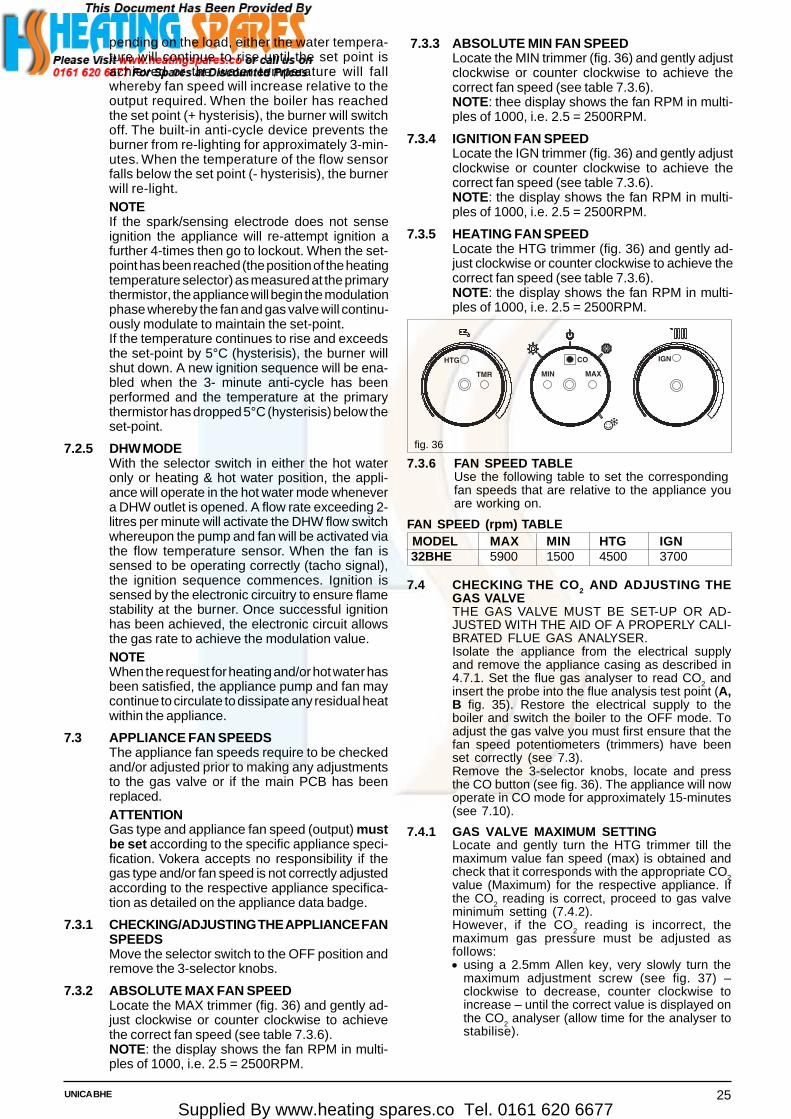
Supplied By www.heating spares.co Tel. 0161 620 667725UNICA BHE
pending on the load, either the water tempera-ture will continue to rise until the set point isachieved or the water temperature will fallwhereby fan speed will increase relative to theoutput required. When the boiler has reachedthe set point (+ hysterisis), the burner will switchoff. The built-in anti-cycle device prevents theburner from re-lighting for approximately 3-min-utes. When the temperature of the flow sensorfalls below the set point (- hysterisis), the burnerwill re-light.NOTEIf the spark/sensing electrode does not senseignition the appliance will re-attempt ignition afurther 4-times then go to lockout. When the set-point has been reached (the position of the heatingtemperature selector) as measured at the primarythermistor, the appliance will begin the modulationphase whereby the fan and gas valve will continu-ously modulate to maintain the set-point.If the temperature continues to rise and exceedsthe set-point by 5°C (hysterisis), the burner willshut down. A new ignition sequence will be ena-bled when the 3- minute anti-cycle has beenperformed and the temperature at the primarythermistor has dropped 5°C (hysterisis) below theset-point.
7.2.5 DHW MODEWith the selector switch in either the hot wateronly or heating & hot water position, the appli-ance will operate in the hot water mode whenevera DHW outlet is opened. A flow rate exceeding 2-litres per minute will activate the DHW flow switchwhereupon the pump and fan will be activated viathe flow temperature sensor. When the fan issensed to be operating correctly (tacho signal),the ignition sequence commences. Ignition issensed by the electronic circuitry to ensure flamestability at the burner. Once successful ignitionhas been achieved, the electronic circuit allowsthe gas rate to achieve the modulation value.NOTEWhen the request for heating and/or hot water hasbeen satisfied, the appliance pump and fan maycontinue to circulate to dissipate any residual heatwithin the appliance.
7.3 APPLIANCE FAN SPEEDSThe appliance fan speeds require to be checkedand/or adjusted prior to making any adjustmentsto the gas valve or if the main PCB has beenreplaced.ATTENTIONGas type and appliance fan speed (output) mustbe set according to the specific appliance speci-fication. Vokera accepts no responsibility if thegas type and/or fan speed is not correctly adjustedaccording to the respective appliance specifica-tion as detailed on the appliance data badge.
7.3.1 CHECKING/ADJUSTING THE APPLIANCE FANSPEEDSMove the selector switch to the OFF position andremove the 3-selector knobs.
7.3.2 ABSOLUTE MAX FAN SPEEDLocate the MAX trimmer (fig. 36) and gently ad-just clockwise or counter clockwise to achievethe correct fan speed (see table 7.3.6).NOTE: the display shows the fan RPM in multi-ples of 1000, i.e. 2.5 = 2500RPM.
7.3.3 ABSOLUTE MIN FAN SPEEDLocate the MIN trimmer (fig. 36) and gently adjustclockwise or counter clockwise to achieve thecorrect fan speed (see table 7.3.6).NOTE: thee display shows the fan RPM in multi-ples of 1000, i.e. 2.5 = 2500RPM.
7.3.4 IGNITION FAN SPEEDLocate the IGN trimmer (fig. 36) and gently adjustclockwise or counter clockwise to achieve thecorrect fan speed (see table 7.3.6).NOTE: the display shows the fan RPM in multi-ples of 1000, i.e. 2.5 = 2500RPM.
7.3.5 HEATING FAN SPEEDLocate the HTG trimmer (fig. 36) and gently ad-just clockwise or counter clockwise to achieve thecorrect fan speed (see table 7.3.6).NOTE: the display shows the fan RPM in multi-ples of 1000, i.e. 2.5 = 2500RPM.
fig. 36
7.3.6 FAN SPEED TABLEUse the following table to set the correspondingfan speeds that are relative to the appliance youare working on.
FAN SPEED (rpm) TABLE MODEL MAX MIN HTG IGN 32BHE 5900 1500 4500 3700
7.4 CHECKING THE CO2 AND ADJUSTING THEGAS VALVETHE GAS VALVE MUST BE SET-UP OR AD-JUSTED WITH THE AID OF A PROPERLY CALI-BRATED FLUE GAS ANALYSER.Isolate the appliance from the electrical supplyand remove the appliance casing as described in4.7.1. Set the flue gas analyser to read CO2 andinsert the probe into the flue analysis test point (A,B fig. 35). Restore the electrical supply to theboiler and switch the boiler to the OFF mode. Toadjust the gas valve you must first ensure that thefan speed potentiometers (trimmers) have beenset correctly (see 7.3).Remove the 3-selector knobs, locate and pressthe CO button (see fig. 36). The appliance will nowoperate in CO mode for approximately 15-minutes(see 7.10).
7.4.1 GAS VALVE MAXIMUM SETTINGLocate and gently turn the HTG trimmer till themaximum value fan speed (max) is obtained andcheck that it corresponds with the appropriate CO2value (Maximum) for the respective appliance. Ifthe CO2 reading is correct, proceed to gas valveminimum setting (7.4.2).However, if the CO
2 reading is incorrect, the
maximum gas pressure must be adjusted asfollows:• using a 2.5mm Allen key, very slowly turn the
maximum adjustment screw (see fig. 37) –clockwise to decrease, counter clockwise toincrease – until the correct value is displayed onthe CO2 analyser (allow time for the analyser tostabilise).
���
��� ��� ��
� ���

Supplied By www.heating spares.co Tel. 0161 620 667726 UNICA BHE
fig. 37
7.4.2 GAS VALVE MINIMUM SETTINGLocate and gently turn the HTG trimmer till theminimum value fan speed (max) is obtained andcheck that it corresponds with the appropriate CO
2value (Minimum) for the respective appliance. Ifthe CO
2 reading is correct, rotate the HTG trim-
mer until the correct value is obtained for the re-spective appliance (see fan speed table) and pro-ceed to 7.4.3. However, if the CO
2 reading is in-
correct, the minimum gas pressure must be ad-justed as follows:• using a suitable screwdriver, very slowly turn the
minimum adjustment screw (see fig. 38) – clock-wise to increase, counter clockwise to decrease- until the correct value is displayed on the CO
2analyser (allow time for the analyser to stabilise).
7.4.3 COMPLETIONOn completion of the combustion analysis checkand/or any gas valve adjustment, set the HTGtrimmer to the corresponding value as detailed inthe fan speed table. Refit the 3-selector knobs andmove the mode selector to the OFF position.Remove the test probe from the test point and refitthe sealing screw/s and/or cap.IMPORTANTA GAS TIGHTNESS CHECK MUST BE CAR-RIED OUT IF ANY GAS CARRYING COMPO-NENTS HAVE BEEN REMOVED, REPLACEDOR DISTURBED.
7.5 COMBUSTION ANALYSIS TESTA combustion analysis check can easily be car-ried out on the appliance via the test points locatedon the top of the appliance (see 7.4).• Insert the flue gas analyser probe into the flue
gas test point (see fig. 35).• Operate the boiler in CO mode and compare the
values with those shown in section 2 (Nat. Gas)or section 10 (LPG). If different adjust the gasvalve according to 7.4.1, 7.4.2, & 7.4.3.
7.6 CHECKING THE EXPANSION VESSELCarry out the component removal procedure asdescribed in 6.4. You must ensure that the boileris completely drained of water. Using a suitablepressure gauge, remove dust cap on expansionvessel and check the charge pressure. The cor-rect charge pressure should be 1.0 bar ± 0.1 bar.If the charge pressure is less, use a suitable pumpto increase the charge.NOTEYou must ensure the drain valve is in the openposition whilst re-charging takes place. Replacethe dust cap and carry out the relevant commis-sioning procedure (section 5).
7.7 EXTERNAL FAULTSBefore carrying out any faultfinding or componentreplacement, ensure the fault is not attributable toany aspect of the installation.
7.7.1 INSTALLATION FAULTS
Symptom Possible cause No display/ignition Check wiring/check electrical
supply No hot water Check pipe-work No heating Check external controls
Fault code Possible cause 10 Check gas supply, check flue
system, check polarity
7.8 ELECTRICAL CHECKSAny electrical checks must be carried out by asuitably qualified person.
7.8.1 EARTH CONTINUITY TESTIsolate the appliance from the electrical supply,and using a suitable multi-meter carry out a resist-ance test. Connect test leads between an appli-ance earth point and the earth wire of the appliancesupply cable. The resistance should be less than1 OHM. If the resistance is greater than 1 OHMcheck all earth wires and connectors for continuityand integrity.
7.8.2 SHORT CIRCUIT CHECKIsolate the appliance from the electrical supply,and using a suitable multi-meter, carry out a shortcircuit test between the Live & Neutral connec-tions at the appliance terminal strip (fig.17). Re-peat above test on the Live & Earth connectionsat the appliance terminal strip (fig.16).NOTEShould it be found that the fuse has failed but nofault is indicated, a detailed continuity check willbe required to trace the fault. A visual inspection ofcomponents may also assist in locating the fault.
7.8.3 POLARITY CHECKWith the appliance connected to the electricalsupply and using a suitable multimeter, carry outthe following voltage tests:• connect test leads between the Live & Neutral
connections at the appliance terminal strip (fig.16).The meter should read approximately 230V ac.If so proceed to next stage. If not, see 7.8.4.
• connect test leads between the Live & Earthconnections at the appliance terminal strip (fig.16).The meter should read approximately 230V ac.If so proceed to next stage. If not, see 7.8.4.
• connect test leads between the Neutral & Earthconnections at the appliance terminal strip (fig.16).The meter should read approximately 0 – 15Vac.If so polarity is correct. If not, see 7.8.4.
7.8.4 REVERSED POLARITY OR SUPPLY FAULTRepeat the above tests at the appliance isolator,if testing reveals correct polarity and/or supply atthe isolator, re-check wiring and connections be-tween the isolator and the appliance. If tests on theisolator also reveal reversed polarity or a supplyfault, consult the local electricity supplier foradvice.
7.8.5 RESISTANCE TO EARTH CHECKIsolate the appliance from the electrical supply, andusing a suitable multi-meter carry out a resistancetest. Connect test leads between the Live & Earthconnections at the appliance terminal strip (fig. 16).If the meter reads other than infinity there is a faultthat must be isolated, carry out a detailed continuitycheck to identify the location of the fault.
Maximumscrew
Minimumscrew
Compensationpipe connection

Supplied By www.heating spares.co Tel. 0161 620 667727UNICA BHE
These series of checks must be carried out be-fore attempting any faultfinding procedures on theappliance. On completion of any task that requiredthe disconnection and re-connection of any elec-trical wiring or component, these checks must berepeated.
7.9 FAULT FINDINGBefore attempting any faultfinding, the electricalchecks as detailed in 7.8 must be carried out.Isolate the appliance from the electrical supply.Disconnect any external controls from terminalplug M6 (fig. 16), and insert a link-wire betweenthe two wires at the ‘TA’ connections (fig. 19).NOTERestore the electrical supply to the boiler and turnthe selector switch to the on position. The boilershould now function as described in section 7.2.Should the boiler fail to respond, the internal fusesand connectors should be checked to ensureintegrity and continuity. If the boiler still fails torespond, refer to the detailed faultfinding flow-charts located at the end of this section.
7.10 BOILER CONFIGURATIONThe boiler can be configured by means of theJUMPER Tag which configuration is shown in thebelow:JP4 CONFIGURATION●●●●● JUMPER ON POSITION 1: FLOOR
HEATING (IF SET)/STANDARDHEATING (IF NOT USED)
●●●●● JUMPER ON POSITION 2: (UNUSED)●●●●● JUMPER ON POSITION 3: (UNUSED)●●●●● JUMPER ON POSITION 4: (UNUSED)●●●●● JUMPER ON POSITION 5: COMBI●●●●● JUMPER ON POSITION 6:
(UNUSED)FOR CONFIGURATION SEEREFERENCE NUMBER (PIN1 ONPCB) AS SHOWN IN BELOW.
7.12 COMPONENT VALUES & CHARACTERISTICS
COMPONENT VALUE Fan 230Vac Pump 230Vac Valve actuator (Combi only) 230Vac Ignition transformer 230Vac Gas valve 230Vac Room thermostat connection 230Vac NTC thermistor (dry contact) 10Kohm NTC thermistor (wet contact) 10Kohm
FUNCTION VALUE Standard Heating temperature range (min – max °C) 40 - 80 Floor Heating temperature range (min – max °C) 20 - 45 DHW temperature range (min – max °C) 35 - 60 75% maximum CH time 15 min Heating OFF hysterisis (°C) SP + 5 Heating ON hysterisis (°C) SP – 5 DHW OFF hysterisis (°C) SP + 5 DHW ON hysterisis (°C) SP + 3 Anti-cycle delay 3-min Pump over-run 30-sec Low output (min. output + %) Min+25 CO function max temp. (°C) 95 CO re-light temp. (°C) 75 CO function time 15-min Flow NTC max temp. (°C) 95 High limit thermostat (°C) 105 Burner thermostat (°C) 170 Maximum differential (°C) 35
IGNITION CONTROL VALUE Ignition attempts before L/O (lockout) 5 Re-ignition attempts after loss of flame signal 5
JP4
7.11 FAULT CODESWhen the boiler detects a temporary fault condition, the appropriate code is shown flashing on the display. If/when thefault code is final, the pump will perform a 60-second post circulation and the red LED will be illuminated.
CODE CAUSE ALARM TYPE ACTIONAL10 Ignition failure, flame not sensed, Final Reset, check appliance operation
condense sensor activatedAL20 Limit thermostat fault/fumes thermostat fault Final Reset, check appliance operationAL21 External device fault (UHT/CPA) Final Reset, check applianceAL26 Return temperature too high Temporary than Reset, check appliance operation,
final check thermistorAL28 Temperature differential inverted Temporary than Reset, check pump, ensure there is sufficient
(return sensor temperature higher than final circulation around heating circuit/sthermistors flowsensor temperature)
AL34 Fan tacho signal fault Final Reset check appliance operation, check fanAL40 Insufficient system water pressure Final Check/refill system pressure, reset,
check appliance operationAL41 Insufficient system water pressure Temporary Check/refill system pressure,
check appliance operationAL52 Internal fault Final Reset, check appliance operationAL55 Jumper tag fault Final Check jumper tag configurationAL60 DHW thermistor fault Temporary Check DHW thermistorAL71 Primary (flow) thermistor fault Temporary Check primary thermistor, check wiringAL73 Return thermistor fault Temporary Check return thermistor, check wiringAL74 Over temperature due to Final Reset, check appliance operation, check
low H2O pressure pump, ensure there is sufficient circulationaround heating circuit/s
AL79 Flow temperature too high, Temporary than Reset, check appliance operation,temperature differential too high final check thermistors

Supplied By www.heating spares.co Tel. 0161 620 667728 UNICA BHE
8.1 EXTERNAL WIRINGThe appliance comes with a factory fitted (TA)link to allow basic operation of the boiler via themode selector switch. If external controls are tobe added to the system, they must be connectedto the appliance as shown in the following dia-grams. For advice on controls that are not fea-tured in this book, please contact Vokera techni-cal on 0844 391 0999.
8.1.1 EXTERNAL WIRING LIMITATIONSAny external wiring must remain within the limitsas detailed in the table below:
CONNECTION MAX. LENGTH External sensor 30-metres Room thermostat 30-metres OT+ connection 30-metres
8.2 TYPICAL CONTROL APPLICATIONSThe appliance can be used with the following con-trols:• single-channel, voltage-free time clocks (fig.
39).• programmable room thermostats (fig. 40).• OT+ control, please contact Vokera technical
for detailed instruction on specific OT+ controls.• vokera external sensor.
8.3 OTHER DEVICESContact the controls manufacturer and/or Vokeratechnical department should you require morespecific information on the suitability of a particu-lar control. Further guidance on the recommendedpractice for the installation of external controls,can be found in CHeSS – HC5/HC6(www.energyefficiency.gov.uk).
SECTION 8 WIRING DIAGRAMS
IMPORTANT• The boiler must always be supplied with a per-
manent 230V electrical supply.• Always remove the link between TA & TA on the
appliance high-voltage terminal strip wheneveradditional controls are connected to the appli-ance.
• Do not connect any controls or auxiliary equip-ment to the low-voltage terminal strip, other thanthat approved/supplied by Vokera Ltd.
Fig. 39
Fig. 41
U.H.T. = underfloor heating thermostatC.P.A.= condensate pump alarmE.S.= external sensorOT+= opentherm + connection
OPTIONAL DEVICE (24V) TERMINAL BLOCK
Fig. 40
������������
�������������
�� ���������
������������
�� ���������
����
������ �!�

Supplied By www.heating spares.co Tel. 0161 620 667729UNICA BHE
FUNCTIONAL DIAGRAM
Fig. 38NOTE: L-N-E connection is advisable
F Hv Fan power supply 230 VF Lv Fan signal controlP PumpF Fuse 3.15A F (fast)F1-F2 Fuse 3.15A T (delay)OPE Gas valve solenoidsS.E. (1) Spark electrodeS.E. (2) Sense electrodeC.S. Condensate sensorG.V. Gas valveTSC2 Ignition transformerTR2 PCB transformerOT+ Open therm + connectionE.S External sensorWPS Water pressure switchFS Flow thermistor (NTC)RS Return thermistor (NTC)AD01X Main PCBCN1÷CN5 Connection to PCB high voltageX2÷X16 Connection to PCB low voltageF.O.H.T Flow over heat thermostatF.T Fume thermostat
G Cable connectorM3-M5 Terminal strip for supply in / clock / room thermostatM2-M4 Terminal strip for condense pump / low temperature
thermostat / open therm + connection / esternal sensorD.H.W.F.S Domestic hot water flow switchD.H.W.T Domestic hot water temperature3W 3 way motorUHT Underfloor heating thermostatCPA Condensate pump alarmJP5 For combi boilerX1 Connector minitank (unused)CN12 Service connectorSW1 Co buttonA1 24V output to 2CH - programmerP1 DHW potentiometerP2 Heating potentiometerP3 Selector switchR9 Trimmer for maximum outputR10 Trimmer for minimum outputR14 Trimmer for ignition fan speedR19 Trimmer for heating fan speedR35 Trimmer thermoregulation

Supplied By www.heating spares.co Tel. 0161 620 667730 UNICA BHE
SECTION 9 EXPLODED DIAGRAMS
POS. DESCRIPTION 32 BHE12 Quick primer pressure gauge R1002889418 Cover 2000076120 Printed circuit board 2000830721 Led light guide R1002855726 Instrumental panel 2001108227 Knob assembly R1002855931 Instrumental panel 2001139340 Door panel R1003013664 Frame assembly R1002880965 Case cover 2001139267 Wiring box R0100546878 Hinge assembly R0100544290 Fuse R3478226 Clip R5128433 Clip R10024986500 Low tension cable 20000764501 Power wiring harness 20000768502 Wiring harness 20000762
90
65
226
12
64
67
78
18
21
20
26
2740
433
31
500
501
502
Table 1

Supplied By www.heating spares.co Tel. 0161 620 667731UNICA BHE
POS. DESCRIPTION 32 BHE1 Exchanger R19572 Fitting/union R98073 Pressure water switch R100281414 Non return valve R29087 Heating by-pass valve R20479 Distributor R1002881210 3 port valve spring R686211 3 way valve overhaul kit R0100512716 Water valve cover R290417 Motorised valve fixing fork wrench R290618 OR union assembly bracket R691919 Actuator R290522 Safety valve R290724 Flow governor R1002004124 Flow governor R943024 Flow governor R132126 Dhw actuator R1002234927 Heating cock R178928 Connection R179030 Water supply stop cock R709931 Venting-plug R1002323537 Pipe R163140 Pipe R1002212541 Fitting/union R290350 Cover 2000769263 Pipe R10027841115 Door panel R10028839200 Washer R5023201 Washer R5026202 Washer R5041248 Washer R5208265 Washer R5236266 Washer R5237290 Clip R2165292 O ring R7999351 Nut R1823353 Nut R1824636 Detector 20004978
24
201
26
40
200
7
201
265
30
200
201
2292
4
202
636
22
31
41
292
1
9
37
10
17202
16
1918
248
266
290
50
27
3
351
28
353
265
63
115
11
Table 2
3
290
28
288
6
2
10
288
476 477
25
26
27
372
512
477
476
247
290
200
17
633
633
7
11
201
2
287
71
73
72
9
200
66
700
Table 3
POS. DESCRIPTION 32 BHE1 Expansion vessel R100288112 Pipe R100236033 Pump 200114026 Pipe R100288187 Pipe R100262679 Pipe R1002945710 Pipe R1002881717 Air venting plug R1002930625 Siphon R1002840526 Flexible pipe R1002719127 Flexible pipe R1002719228 Key R926366 Flexible pipe R1002627271 Pipe R1002851672 Venting-plug R1002323573 Cock R10028431200 Washer R5023201 Washer R5026247 Washer R5203287 High limit thermostat R2258288 Ring R6898290 Clip R2165372 Clip R2588476 O ring R10026324477 Split pin R10026269512 Washer R10027193633 Detector 20003819700 Pump cable 20000763

Supplied By www.heating spares.co Tel. 0161 620 667732 UNICA BHE
POS. DESCRIPTION 32 BHE2 Roomsealed chamber side R100262313 Fan R100284564 Burner assembly R100286425 Spark / ignition electrode R100278646 Condense electrode R1002631612 Gas pipe R1002881413 Gas valve R1002853814 Gas pipe R1002881315 Gas cock 2001140316 Chamber cover R1002623019 Glass stopper assembly R1002632827 Plug R1002380535 Air gas conveyor R1002842039 Pipe 2000076946 Gas diaphragm R1002716167 Washer Ø 62 R1002632269 Tryton R1002842572 Mixer R1002429579 Flame detection electrode R1002842288 Fan baffle 20006411200 Washer R5023486 O ring R10026325497 Washer R10026796613 Ignition transformer 20001563700 Combustion-fan cable 20001617701 Spark electrode cable R10026558702 Gas valve cable 20000767
Table 4
200
13
12
200
14
200
613
46
39
2
2
1627
15
27
69
4
519
6
35
67
72
486
638
79
700
701
702
88
3

Supplied By www.heating spares.co Tel. 0161 620 667733UNICA BHE
Table 5
POS. DESCRIPTION 32 BHE1 Condensing exchanger assembly R010053667 Conveyor R1002862312 Flue drain connection R1002842127 Nut screw R10020625475 Washer Ø 125 R10026323482 Washer R10026366487 Washer Ø 60 R10026345552 Washer Ø 60 R10028426614 High limit thermostat 20001564700 Combustion cable 20000765
482
475
1
700
27
12487
614
7
552

Supplied By www.heating spares.co Tel. 0161 620 667734 UNICA BHE
SECTION 10 LPG INSTRUCTIONS
10.1 RELATED DOCUMENTS
BS 5440 PARTS 1 & 2 FLUES & VENTILATION REQUIREMENTS
BS 5449 PART 1 FORCED CIRCULATION OF HOT WATER SYSTEMS
BS 5482 PART 1 DOMESTIC BUTANE & PROPANE GAS BURNERS IN PERMAMENTDWELLINGS
BS 5546 INSTALLATION OF GAS HOT WATER SUPPLIES FOR DOMESTICPURPOSES
BS 6798 INSTALLATION OF BOILERS OF RATED NOT EXCEEDING 60kW
10.2 TECHNICAL DATAGas Pressures Unica 32BHEInlet pressure 37.0mbarMaximum gas rate (kg/hr) 2.48Minimum gas rate (kg/hr) 0.54Injector size 4.7mmCO2 max (%) 10.0CO2 min (%) 10.0CO max (mg/kWh) 200CO min (mg/kWh) 20NOx max (PPM) mg/kWh 50
NOx min (PPM) mg/kWh 30
CO/CO2 ratio @ max 0.002 to 1CO/CO2 ratio @ min 0.0002 to 1
SEDBUK ‘A’ (%) 92.7
10.3 CONVERTING THE APPLIANCE GAS TYPETo convert the appliance to another gas type it isnecessary to change the burner injector, adjustthe appliance fan speeds and adjust the gas valve(CO
2).
• To change the injector see 6.12.1• To adjust the fan speeds see 10.7• To adjust CO2 values see 10.6
10.4 GAS SUPPLYThe gas supply must be connected to the appli-ance by a competent LPG installer and must beof sufficient size to supply the appliance at itsmaximum output. An existing supply must bechecked to ensure that it is of adequate size todeal with the maximum rated input of this andany other appliances that it serves.
10.5 GAS SUPPLY INSTALLATIONThe entire installation including the meter mustbe purged and checked for gas tightness.
10.6 CHECKING THE CO2 AND ADJUSTING THEGAS VALVETHE GAS VALVE MUST BE SET-UP OR AD-JUSTED WITH THE AID OF A PROPERLY CALI-BRATED FLUE GAS ANALYSER.Isolate the appliance from the electrical supplyand remove the appliance casing as described in4.7.1. Set the flue gas analyser to read CO
2 and
insert the probe into the flue analysis test point (A,B fig. 35). Restore the electrical supply to theboiler and switch the boiler to the OFF mode. Toadjust the gas valve you must first ensure that thefan speed potentiometers (trimmers) have beenset correctly (see 10.7).Remove the 3-selector knobs, locate and pressthe CO button (fig. 36). The appliance will now
operate in CO mode for approximately 15-minutes(see 7.10).
10.6.1 GAS VALVE MAXIMUM SETTINGLocate and gently turn the HTG trimmer till themaximum value fan speed (max) is obtained andcheck that it corresponds with the appropriate CO
2
value (maximum) for the respective appliance. Ifthe CO
2 reading is correct, proceed to gas valve
minimum setting (10.6.2).However, if the CO
2 reading is incorrect, the
maximum gas pressure must be adjusted asfollows:• using a 2.5mm Allen key, very slowly turn the
maximum adjustment screw (fig. 38) – clock-wise to decrease, counter clockwise to increase– until the correct value is displayed on the CO
2
analyser (allow time for the analyser to stabi-lise).
10.6.2 GAS VALVE MINIMUM SETTINGLocate and gently turn the HTG trimmer till theminimum value fan speed (min) is obtained andcheck that it corresponds with the appropriate CO
2
value (minimum) for the respective appliance. Ifthe CO
2 reading is correct, rotate the HTG trim-
mer until the correct value is obtained for the re-spective appliance (see fan speed table) and pro-ceed to 10.6.3.However, if the CO
2 reading is incorrect, the mini-
mum gas pressure must be adjusted as follows:• using a suitable screwdriver, very slowly turn the
minimum adjustment screw (fig. 38) – clockwiseto increase, counter clockwise to decrease -until the correct value is displayed on the CO
2
analyser (allow time for the analyser to stabi-lise).

Supplied By www.heating spares.co Tel. 0161 620 667735UNICA BHE
10.6.3 COMPLETIONOn completion of the combustion analysis checkand/or any gas valve adjustment, set the HTGtrimmer to the corresponding value as detailed inthe fan speed table. Refit the 3-selector knobs andmove the mode selector to the OFF position.Remove the test probe from the test point and refit.
IMPORTANTA GAS TIGHTNESS CHECK MUST BE CAR-RIED OUT IF ANY GAS CARRYING COMPO-NENTS HAVE BEEN REMOVED, REPLACED,OR DISTURBED.
FAN SPEED (rpm) TABLE - LPG
MODEL MAX MIN HTG IGN
32BHE 5900 1500 4500 3700
10.7 APPLIANCE FAN SPEEDSThe appliance fan speeds require to be checkedand/or adjusted prior to making any adjustmentsto the gas valve or if the main PCB has beenreplaced.
ATTENTIONGas type and appliance fan speed (output) mustbe set according to the specific appliance speci-fication. Vokera accepts no responsibility if thegas type and/or fan speed is not correctly adjustedaccording to the respective appliance specifica-tion as detailed on the appliance data badge.
10.7.1 CHECKING/ADJUSTING THE APPLIANCE FANSPEEDSMove the selector switch to the OFF position andremove the 3-selector knobs.
10.7.2 ABSOLUTE MAX FAN SPEEDLocate the MAX trimmer (fig. 36) and gently adjustclockwise or counter clockwise to achieve thecorrect fan speed (see table above).NOTE: the display shows the fan RPM in multiplesof 1000, i.e. 2.5 = 2500RPM.
10.7.3 ABSOLUTE MIN FAN SPEEDLocate the MIN trimmer (fig. 36) and gently adjustclockwise or counter clockwise to achieve thecorrect fan speed (see table above).NOTE: the display shows the fan RPM in multi-ples of 1000, i.e. 2.5 = 2500RPM.
10.7.4 IGNITION FAN SPEEDLocate the IGN trimmer (fig. 36) and gently adjustclockwise or counter clockwise to achieve thecorrect fan speed (see table above).NOTE: the display shows the fan RPM in multi-ples of 1000, i.e. 2.5 = 2500RPM.
10.7.5 HEATING FAN SPEEDLocate the HTG trimmer (fig. 36) and gently ad-just clockwise or counter clockwise to achievethe correct fan speed (see table above).NOTE: the display shows the fan RPM in multi-ples of 1000, i.e. 2.5 = 2500RPM.

Supplied By www.heating spares.co Tel. 0161 620 6677
GAS BOILER SYSTEM COMMIS SIONING CHEC KLIST
CONTROLS Tick the appropriate boxes
Time and Temperature Control to Heating Room Thermostat and Programmable Load/Weather Optimum Start Programmer/Timer Room Thermostat Compensation Control
Time and Temperature Control to Hot Water Cylinder Thermostat and Programmer/Timer Combination Boiler Heating Zone Valves Fitted Not Required Hot Water Zone Valves Fitted Not Required Thermostatic Radiator Valves Fitted Not Required Automatic Bypass to System Fitted Not Required Boiler Interlock Provided
ALL SYSTEMS
The system has been fl ushed and cleaned in accordance with BS7593 and boiler manufacturer’s instructions Yes
What system cleaner was used?
What inhibitor was used? Quantity litres
CENTRAL HEATING MODE Measure and Record:
Gas Rate m3/hr OR ft3/hr
Burner Operating Pressure (if applicable) mbar OR Gas Inlet Pressure mbar
Central Heating Flow Temperature ˚C
Central Heating Return Temperature ˚C
COMBINATION BOILERS ONLY
Is the installation in a hard water area (above 200ppm)? Yes No
If yes, has a water scale reducer been fitted? Yes No
What type of scale reducer has been fitted?
DOMESTIC HOT WATER MODE Measure and Record:
Gas Rate m3/hr OR ft3/hr
Burner Operating Pressure (at maximum rate) mbar OR Gas Inlet Pressure (at maximum rate) mbar
Cold Water Inlet Temperature ˚C
Hot water has been checked at all outlets Yes Temperature ˚C
Water Flow Rate l/min
CONDENSING BOILERS ONLY
The condensate drain has been installed in accordance with the manufacturer’s instructions and/or BS5546/BS6798 Yes
ALL INSTALLATIONS
If required by the manufacturer, record the following CO2 % OR CO ppm OR CO/CO2 Ratio
The heating and hot water system complies with the appropriate Building Regulations Yes
The boiler and associated products have been installed and commissioned in accordance with the manufacturer’s instructions Yes
The operation of the boiler and system controls have been demonstrated to and understood by the customer Yes
The manufacturer’s literature, including Benchmark Checklist and Service Record, has been explained and left with the customer Yes
* All installations in England and Wales must be notified to Local Authority Building Control (LABC) either directly or through a Competent Persons Scheme. A Building Regulations Compliance Certificate will then be issued to the customer.
©Heating and Hotwater Industry Council (HHIC) www.centralheating.co.uk
Commissioning Engineer’s Signature
Customer’s Signature(To con r m satisfactory demonstration and receipt of manufacturer’s literature)
This Commissioning Checklist is to be completed in full by the competent person who commissioned the boiler as a means of demonstrating compliance with the appropriate Building Regulations and then handed to the customer to keep for future reference.
Failure to install and commission this equipment to the manufacturer’s instructions may invalidate the warranty but does not affect statutory rights.
Customer Name Telephone Number
Address
Boiler Make and Model
Boiler Serial Number
Commissioned by (print name) CORGI ID Number
Company Name Telephone Number
Company Address
Commissioning Date
To be completed by the customer on receipt of a Building Regulations Compliance Certi ficate*:
Building Regulations Notification Number (if applicable)

Supplied By www.heating spares.co Tel. 0161 620 6677
SERVICE RECORDIt is recommended that your heating system is serviced regularly and that the appropriate Service Record is completed.
Service Provider Before completing the appropriate Service Record below, please ensure you have carried out the service as described in the manufacturer’s instructions.
Always use the manufacturer’s specified spare part when replacing controls.
SERVICE 1 Date
Energy Efficiency Checklist completed? Yes No
Engineer Name
Company Name
Telephone Number
CORGI ID Number
Comments
Signature
SERVICE 3 Date
Energy Efficiency Checklist completed? Yes No
Engineer Name
Company Name
Telephone Number
CORGI ID Number
Comments
Signature
SERVICE 5 Date
Energy Efficiency Checklist completed? Yes No
Engineer Name
Company Name
Telephone Number
CORGI ID Number
Comments
Signature
SERVICE 7 Date
Energy Efficiency Checklist completed? Yes No
Engineer Name
Company Name
Telephone Number
CORGI ID Number
Comments
Signature
SERVICE 9 Date
Energy Efficiency Checklist completed? Yes No
Engineer Name
Company Name
Telephone Number
CORGI ID Number
Comments
Signature
SERVICE 2 Date
Energy Efficiency Checklist completed? Yes No
Engineer Name
Company Name
Telephone Number
CORGI ID Number
Comments
Signature
SERVICE 4 Date
Energy Efficiency Checklist completed? Yes No
Engineer Name
Company Name
Telephone Number
CORGI ID Number
Comments
Signature
SERVICE 6 Date
Energy Efficiency Checklist completed? Yes No
Engineer Name
Company Name
Telephone Number
CORGI ID Number
Comments
Signature
SERVICE 8 Date
Energy Efficiency Checklist completed? Yes No
Engineer Name
Company Name
Telephone Number
CORGI ID Number
Comments
Signature
SERVICE 10 Date
Energy Efficiency Checklist completed? Yes No
Engineer Name
Company Name
Telephone Number
CORGI ID Number
Comments
Signature

Supplied By www.heating spares.co Tel. 0161 620 6677
Registered address:Vokèra Ltd
Borderlake HouseUnit 7 Riverside Industrial Estate
London ColneyHerts AL2 1HG
www.vokera.co.ukwww.vokera.ie
Sales, General EnquiresT 0844 391 099
F 0844 391 0998
Vokèra IrelandWest Court, Callan
Co KilkennyT 056 7755057F 056 7755060
Vokèra Limited reserve the right to changespecification without prior notice
Consumers statutory rights are not affected.
A Riello Group Company.Company Reg No: 1047779 C
od. 2
0001
096
- 04/0
9 - E
d. 0